KR102108825B1 - Apparatus and method for communication in nanonetwork - Google Patents
Apparatus and method for communication in nanonetwork Download PDFInfo
- Publication number
- KR102108825B1 KR102108825B1 KR1020180074596A KR20180074596A KR102108825B1 KR 102108825 B1 KR102108825 B1 KR 102108825B1 KR 1020180074596 A KR1020180074596 A KR 1020180074596A KR 20180074596 A KR20180074596 A KR 20180074596A KR 102108825 B1 KR102108825 B1 KR 102108825B1
- Authority
- KR
- South Korea
- Prior art keywords
- pulse
- network communication
- code
- communication device
- spreading code
- Prior art date
- Legal status (The legal status is an assumption and is not a legal conclusion. Google has not performed a legal analysis and makes no representation as to the accuracy of the status listed.)
- Active
Links
- 238000004891 communication Methods 0.000 title claims abstract description 54
- 238000000034 method Methods 0.000 title claims description 27
- 230000007480 spreading Effects 0.000 claims abstract description 35
- 238000010586 diagram Methods 0.000 description 8
- 238000002922 simulated annealing Methods 0.000 description 7
- 238000004088 simulation Methods 0.000 description 7
- 230000005540 biological transmission Effects 0.000 description 6
- 230000008569 process Effects 0.000 description 4
- 238000012546 transfer Methods 0.000 description 4
- 238000010521 absorption reaction Methods 0.000 description 2
- 230000010355 oscillation Effects 0.000 description 2
- 230000004044 response Effects 0.000 description 2
- 239000000654 additive Substances 0.000 description 1
- 230000000996 additive effect Effects 0.000 description 1
- 238000004364 calculation method Methods 0.000 description 1
- 230000002596 correlated effect Effects 0.000 description 1
- 230000000875 corresponding effect Effects 0.000 description 1
- 238000011161 development Methods 0.000 description 1
- 230000000694 effects Effects 0.000 description 1
- 230000001788 irregular Effects 0.000 description 1
- 238000005259 measurement Methods 0.000 description 1
- 238000012986 modification Methods 0.000 description 1
- 230000004048 modification Effects 0.000 description 1
- 230000003287 optical effect Effects 0.000 description 1
- 238000012545 processing Methods 0.000 description 1
- 238000010791 quenching Methods 0.000 description 1
- 239000004065 semiconductor Substances 0.000 description 1
- 230000008054 signal transmission Effects 0.000 description 1
- 230000001360 synchronised effect Effects 0.000 description 1
- XLYOFNOQVPJJNP-UHFFFAOYSA-N water Substances O XLYOFNOQVPJJNP-UHFFFAOYSA-N 0.000 description 1
Images


Classifications
-
- H—ELECTRICITY
- H04—ELECTRIC COMMUNICATION TECHNIQUE
- H04B—TRANSMISSION
- H04B1/00—Details of transmission systems, not covered by a single one of groups H04B3/00 - H04B13/00; Details of transmission systems not characterised by the medium used for transmission
- H04B1/69—Spread spectrum techniques
- H04B1/707—Spread spectrum techniques using direct sequence modulation
- H04B1/7097—Interference-related aspects
- H04B1/7103—Interference-related aspects the interference being multiple access interference
-
- H—ELECTRICITY
- H04—ELECTRIC COMMUNICATION TECHNIQUE
- H04B—TRANSMISSION
- H04B1/00—Details of transmission systems, not covered by a single one of groups H04B3/00 - H04B13/00; Details of transmission systems not characterised by the medium used for transmission
- H04B1/69—Spread spectrum techniques
- H04B1/7163—Spread spectrum techniques using impulse radio
- H04B1/717—Pulse-related aspects
- H04B1/7174—Pulse generation
Landscapes
- Engineering & Computer Science (AREA)
- Computer Networks & Wireless Communication (AREA)
- Signal Processing (AREA)
- Mobile Radio Communication Systems (AREA)
Abstract
본 실시예는, 테라헤르츠 대역 기반의 나노네트워크 통신장치로서, 기 설정된 듀티 사이클을 갖는 펄스를 생성하는 펄스 발생기, 상기 생성된 펄스와 사용자 데이터에 대해 확산 코드(spreading code)를 이용한 DS-OOK 변조를 수행하여 변조신호를 생성하는 변조기, 및 상기 변조신호를 테라헤르츠 대역 채널을 통해 송출하는 송신 안테나를 포함하는 송신기, 및 상기 송출된 변조신호를 상기 확산 코드와 동일한 코드를 이용하여 복조하는 수신기를 포함하되, 상기 수신기는, 예상 지연(expected delay) 및 확산 코드(spreading code) 정보가 알려진 특정 송신기를 제외한 나머지 송신기로부터 수신된 신호를 장애로 간주하는, 나노네트워크 통신장치를 제공한다.This embodiment is a terahertz band-based nano network communication device, a pulse generator for generating a pulse having a predetermined duty cycle, DS-OOK modulation using a spreading code for the generated pulse and user data A modulator for generating a modulated signal by performing, and a transmitter including a transmit antenna for transmitting the modulated signal through a terahertz band channel, and a receiver for demodulating the transmitted modulated signal using the same code as the spreading code. Including, the receiver provides a nano-network communication device that considers a signal received from a transmitter other than a specific transmitter for which predicted delay and spreading code information is known.
Description
본 발명의 실시예들은 나노네트워크 통신장치 및 방법에 관한 것이다.Embodiments of the present invention relate to a nanonetwork communication device and method.
이하에 기술되는 내용은 단순히 본 발명에 따른 실시예들과 관련되는 배경 정보만을 제공할 뿐 종래기술을 구성하는 것이 아니다.The contents described below merely provide background information related to the embodiments according to the present invention, and do not constitute the prior art.
1959년 리차드 파인만(Richard Feynman) 교수에 의해 최초로 논의된 나노기술은 현재 나노머신(nanomachine)으로 일컬어지는 나노 스케일 장치의 프로토타입을 제작하는 데 사용되고 있다. 나노머신은 수백 나노미터 단위의 크기로 제작되어 단순 계산, 센싱 등과 같은 간단한 작업을 수행할 수 있는 장치를 말한다. 나노머신은 센싱 범위, 배터리 및 처리능력이 제한적이므로 나노네트워크(nanonetwork)의 형태로 연결되어야만 복잡한 작업을 수행할 수 있다.The nanotechnology, first discussed by Professor Richard Feynman in 1959, is now being used to prototype nanoscale devices called nanomachines. A nanomachine is a device that can be manufactured in the size of hundreds of nanometers and perform simple tasks such as simple calculation and sensing. Since the nano-machine has limited sensing range, battery, and processing power, it can only perform complex tasks when it is connected in the form of a nanonetwork.
나노네트워크는 매우 많은 수의 나노장치들로 구성된 랜덤(random) 네트워크이므로, 원활한 통신을 수행하기 위하여 나노장치들의 채널(channel) 동시접속을 지원하는 변조(modulation) 기법 및 다중접속(multiple access: MA) 기법의 개발이 요청되고 있다. 그리고, 이와 같은 요청에 부응하는 나노네트워크 통신기법으로서 TS-OOK(time spread OOK)와 RD(rate division) TS-OOK가 있다.Since the nanonetwork is a random network composed of a very large number of nanodevices, a modulation technique and multiple access (MA) that supports simultaneous channel access of nanodevices to perform smooth communication ) Development of techniques is being requested. In addition, there are time spread OOK (TS-OOK) and rate division (RD) TS-OOK as nano-network communication techniques that meet such requests.
TS-OOK는, 펄스 폭보다 매우 큰, 사용자별 고유의 전송간격(transmission interval)을 갖는 심볼(symbol)을 이용함으로써 시간확산(time spread) 다중접속을 지원한다. 즉, TS-OOK 기법을 이용하는 경우, 수신기는 사용자별로 상이하고 펄스 폭보다 매우 큰 신호 전송간격을 통해 다수의 사용자(즉, 송신기)로부터 전송된 신호들을 구별할 수 있게 된다.TS-OOK supports time spread multiple access by using symbols having a transmission interval unique to each user, which is much larger than a pulse width. That is, when using the TS-OOK technique, the receiver is able to distinguish signals transmitted from multiple users (ie, transmitters) through signal transmission intervals that are different for each user and are much larger than the pulse width.
또한, RD TS-OOK는 사용자별로 상이한 심볼 레이트(symbol rate)로 사용자 데이터를 전송함으로써 속도분할(rate division) 다중접속을 지원한다. 즉, RD TS-OOK 기법을 이용하는 경우, 수신기는 사용자별로 상이한 심볼 레이트를 통해 다수의 사용자(즉, 송신기)로부터 전송된 신호들을 구별할 수 있게 된다.In addition, RD TS-OOK supports rate division multiple access by transmitting user data at a different symbol rate for each user. That is, when using the RD TS-OOK technique, the receiver can distinguish signals transmitted from multiple users (ie, transmitters) through different symbol rates for each user.
도 1은 TS-OOK 기법을 이용한 나노네트워크 통신장치를 나타낸 개념도이다.1 is a conceptual diagram showing a nano-network communication device using the TS-OOK technique.
TS-OOK 기법을 이용한 나노네트워크 통신장치(100)는 펄스 발생기(112), 변조기(114) 및 송신 안테나(116)를 포함하는 송신기(110) 및 수신 안테나(122), 검출기(124) 및 복조기(126)를 포함하는 수신기(120)을 포함한다.The nano-
펄스 발생기(112)는 펄스를 생성하여 변조기(114)로 전달한다. 변조기(114)는 펄스 발생기(112)에 의해 생성된 펄스 및 사용자 데이터에 기반하여 TS-OOK 변조를 수행하여 변조신호를 생성한다. 여기서, 변조신호의 심볼 간격(symbol interval)은 각 사용자(즉, 송신기)별로 상이하므로, 수신기에서 다중접속(multiple access: MA)이 가능하게 된다.The
변조기(114)는 타이밍 정보 생성기(115)를 더 포함할 수 있다. 타이밍 정보 생성기(115)는 송신기(110) 및 수신기(120)의 동기화에 이용되는 타이밍 정보를 생성한다. 예컨대, 타이밍 정보 생성기(115)는 시간 정보를 제공하기 위한 프리앰블(preamble) 정보를 생성한다. 그리고, 송신기(110)에 의해 생성된 변조신호는 송신 안테나(116)에 의해 채널을 통해 송출된다. 수신기(120)의 검출기(124)는 수신 안테나(122)를 통해 수신된 변조신호를 검출하고, 복조기(126)는 검출된 변조신호를 복조(demodulation)하여 사용자 데이터를 복원한다.The
그러나, 이와 같은 TS-OOK 기법을 이용한 나노네트워크 통신장치(100)는, 서로 다른 송신기로부터 전송된 신호들의 펄스가 오버랩(overlap)되는 경우, 수신신호들이나 잡음(noise)을 상호 구별하기 어렵다는 문제가 있다.However, the nano-
따라서, 나노네트워크에 있어서, 복잡도(complexity)가 낮고 에너지 효율은 높으며, 최소한의 간섭을 일으키면서도 다중접속을 지원할 수 있는 통신 기법이 필요하다.Therefore, in the nano-network, there is a need for a communication technique capable of supporting multiple accesses with low complexity, high energy efficiency, and minimal interference.
본 발명의 실시예들은 복잡도가 낮고 에너지 효율은 높으면서도 최소한의 간섭으로 다중접속 통신을 가능하게 하는 나노네트워크 통신장치 및 방법을 제공하고자 한다.Embodiments of the present invention are to provide a nano-network communication apparatus and method for enabling multiple access communication with minimal interference while having low complexity and high energy efficiency.
본 실시예의 일 측면에 의하면, 테라헤르츠 대역(Terahertz band) 기반의 나노네트워크 통신장치로서, 소정의 듀티 사이클을 갖는 펄스를 생성하는 펄스 발생기, 상기 생성된 펄스와 사용자 데이터에 대해 확산 코드(spreading code)를 이용한 DS-OOK 변조를 수행하여 변조신호를 생성하는 변조기, 및 상기 변조신호를 테라헤르츠 대역 채널을 통해 송출하는 송신 안테나를 포함하는 송신기; 및 상기 송출된 변조신호를 상기 확산 코드와 동일한 코드를 이용하여 복조하는 수신기를 포함하되, 상기 수신기는, 예상 지연(expected delay) 및 확산 코드(spreading code) 정보가 알려진 특정 송신기를 제외한 나머지 송신기로부터 수신된 신호를 장애로 간주하는, 나노네트워크 통신장치를 제공한다.According to an aspect of the present embodiment, a terahertz band (Terahertz band) -based nano-network communication apparatus, a pulse generator for generating a pulse having a predetermined duty cycle, the generated pulse and user data spreading code (spreading code) A transmitter including a modulator that generates a modulated signal by performing DS-OOK modulation using), and a transmit antenna that transmits the modulated signal through a terahertz band channel; And a receiver that demodulates the transmitted modulated signal using the same code as the spreading code, wherein the receiver is from a transmitter other than a specific transmitter for which predicted delay and spreading code information is known. Provided is a nano-network communication device that regards a received signal as an obstacle.
본 실시예의 다른 측면에 의하면, 테라헤르츠 대역 기반의 나노네트워크 통신방법으로서, 소정의 듀티 사이클을 갖는 펄스를 생성하는 단계; 상기 생성된 펄스 및 사용자 데이터에 대해 확산 코드(spreading code)를 이용한 DS-OOK 변조를 수행하여 변조신호를 생성하는 단계; 및 상기 생성된 변조신호를 테라헤르츠 대역 채널을 통해 송출하는 단계를 포함하되, 상기 송출된 변조신호는 상기 확산 코드와 동일한 코드를 이용하여 복조되고, 예상 지연(expected delay) 및 확산 코드(spreading code) 정보가 알려진 특정 송신기를 제외한 나머지 송신기로부터 송출된 신호는 장애로 간주되는, 나노네트워크 통신방법을 제공한다.According to another aspect of this embodiment, a terahertz band-based nanonetwork communication method, comprising: generating a pulse having a predetermined duty cycle; Generating a modulated signal by performing DS-OOK modulation using a spreading code on the generated pulse and user data; And transmitting the generated modulation signal through a terahertz band channel, wherein the transmitted modulation signal is demodulated using the same code as the spreading code, and an expected delay and spreading code. ) A signal transmitted from a transmitter other than a specific transmitter for which information is known provides a nanonetwork communication method, which is regarded as a failure.
본 실시예에 따른 테라헤르츠 대역 기반 나노네트워크 통신장치 및 방법은 최소한의 간섭으로 다중접속 통신을 지원할 수 있는 효과가 있다.The terahertz band-based nano network communication apparatus and method according to the present embodiment has an effect of supporting multiple access communication with minimal interference.
도 1은 TS-OOK 기법을 이용한 나노네트워크 통신장치를 나타낸 개념도이다.
도 2는 본 실시예의 일 측면에 따른 나노네트워크 통신장치를 나타낸 개념도이다.
도 3은 본 실시예에서 이용될 수 있는 펄스 파형을 나타낸 예시도이다.
도 4는 본 실시예의 다른 측면에 따른 나노네트워크 통신장치를 나타낸 개념도이다.
도 5는 본 실시예에 따른 나노네트워크에서 복수의 송신기가 존재하는 경우의 통신장치를 나타낸 개념도이다.
도 6은 본 실시예에 따른 나노네트워크 통신장치에 의사랜덤 이진 코드를 적용하여 시뮬레이션한 결과를 나타낸 그래프이다.
도 7은 본 실시예에 따른 나노네트워크 통신장치에 시뮬레이티드 어닐링 코드를 적용하여 시뮬레이션한 결과를 나타낸 그래프이다.
도 8은 본 실시예에 따른 나노네트워크 통신장치에 의사랜덤 이진 코드 및 시뮬레이티드 어닐링 코드를 적용한 경우에 있어서 성능 비교 결과를 나타낸 그래프이다.
도 9는 본 실시예에 따른 나노네트워크 통신방법을 나타낸 흐름도이다.1 is a conceptual diagram showing a nano-network communication device using the TS-OOK technique.
2 is a conceptual diagram showing a nano-network communication device according to an aspect of the present embodiment.
3 is an exemplary view showing a pulse waveform that can be used in this embodiment.
4 is a conceptual diagram illustrating a nano network communication device according to another aspect of the present embodiment.
5 is a conceptual diagram illustrating a communication device when a plurality of transmitters are present in the nanonetwork according to the present embodiment.
6 is a graph showing a simulation result by applying a pseudo-random binary code to the nano network communication apparatus according to the present embodiment.
7 is a graph showing a simulation result by applying a simulated annealing code to the nanonetwork communication device according to the present embodiment.
8 is a graph showing performance comparison results when a pseudo-random binary code and a simulated annealing code are applied to a nanonetwork communication device according to the present embodiment.
9 is a flowchart illustrating a nanonetwork communication method according to the present embodiment.
이하, 본 발명의 일부 실시예들을 예시적인 도면을 통해 상세하게 설명한다. 각 도면의 구성요소들에 참조부호를 부가함에 있어서, 동일한 구성요소들에 대해서는 비록 다른 도면상에 표시되더라도 가능한 한 동일한 부호를 가지도록 하고 있음에 유의하여야 한다. 또한, 본 발명의 실시예를 설명함에 있어, 관련된 공지 구성 또는 기능에 대한 구체적인 설명이 본 발명의 요지를 흐릴 수 있다고 판단되는 경우에는 그 상세한 설명은 생략한다.Hereinafter, some embodiments of the present invention will be described in detail through exemplary drawings. It should be noted that in adding reference numerals to components of each drawing, the same components have the same reference numerals as possible, even if they are displayed on different drawings. In addition, in describing embodiments of the present invention, when it is determined that detailed descriptions of related well-known structures or functions may obscure the subject matter of the present invention, detailed descriptions thereof will be omitted.
또한, 본 발명의 구성 요소를 설명하는 데 있어서, 제 1, 제 2, A, B, (a), (b) 등의 용어를 사용할 수 있다. 이러한 용어는 그 구성 요소를 다른 구성 요소와 구별하기 위한 것일 뿐, 그 용어에 의해 해당 구성 요소의 본질이나 차례 또는 순서 등이 한정되지 않는다. 명세서 전체에서, 어떤 부분이 어떤 구성요소를 '포함', '구비'한다고 할 때, 이는 특별히 반대되는 기재가 없는 한 다른 구성요소를 제외하는 것이 아니라 다른 구성요소를 더 포함할 수 있는 것을 의미한다. 또한, 명세서에 기재된 '…부,' '모듈' 등의 용어는 적어도 하나의 기능이나 동작을 처리하는 단위를 의미하며, 이는 하드웨어나 소프트웨어 또는 하드웨어 및 소프트웨어의 결합으로 구현될 수 있다.In addition, in describing the components of the present invention, terms such as first, second, A, B, (a), and (b) may be used. These terms are only for distinguishing the component from other components, and the nature, order, or order of the component is not limited by the term. Throughout the specification, when a part is 'included' or 'equipped' a component, this means that other components may be further included rather than excluded, unless specifically stated otherwise. . In addition, '… The terms "unit" and "unit" mean a unit that processes at least one function or operation, which may be implemented by hardware or software or a combination of hardware and software.
이하, 첨부된 도면들을 참조하여 본 발명의 일 실시예들에 대해서 보다 상세하게 설명하기로 한다.Hereinafter, exemplary embodiments of the present invention will be described in detail with reference to the accompanying drawings.
도 2는 본 실시예의 일 측면에 따른 나노네트워크 통신장치를 나타낸 개념도이고, 도 3은 본 실시예에서 이용될 수 있는 펄스 파형을 나타낸 예시도이다.2 is a conceptual diagram showing a nano-network communication apparatus according to an aspect of the present embodiment, Figure 3 is an exemplary view showing a pulse waveform that can be used in this embodiment.
도 2를 참조하면, 나노네트워크 통신장치(200)는 송신기(210) 및 수신기(220)를 포함한다.Referring to FIG. 2, the
송신기(210)는 펄스 발생기(212), 변조기(214) 및 송신 안테나(216)를 포함할 수 있다.The
펄스 발생기(212)는 기 설정된 펄스 지속시간(pulse duration)과 기 설정된 듀티 사이클(duty cycle)을 갖는 펄스를 생성한다. 여기서, 펄스의 주파수는 0.1 THz부터 10 THz 사이의 주파수를 가질 수 있다. 즉, 펄스의 폭은 10 fs보다 크거나 같고 10000 fs보다 작을 수 있다.The
펄스 발생기(212)는 전통적인 반도체 장치, 예컨대, 발진기(oscillator), 증폭기(amplifier), 주파수 체배기(frequency multiplier) 등을 이용하여 구현될 수 있으며, 그 구체적인 구현 방법은 통상의 기술자에게 자명하므로 자세한 설명은 생략하기로 한다.The
도 3을 참조하면, 펄스 발생기(212)에 의해 생성된 펄스 p(t)는 수백 펨토초(femtosecond)의 펄스-폭(pulse-width)을 갖는 가우시안 모노사이클 펄스(Gaussian monocycle pulse)일 수 있다. 그리고, 펄스 지속시간(pulse duration)은 Tp, 심볼 지속시간(symbol duration)은 Ts라고 가정할 때, 듀티 사이클(duty cycle)은 Tp/Ts가 되며, 펄스 p(t)는 수학식 1로 표현될 수 있다.Referring to FIG. 3, the pulse p (t) generated by the
![]()
![]()
여기서, e는 자연 상수이고, A는 펄스 p(t)의 크기(amplitude)이며, fc는 펄스 p(t)의 중심 주파수이다.Here, e is a natural constant, A is the amplitude of the pulse p (t), and f c is the center frequency of the pulse p (t).
다시 도 2로 돌아와, 변조기(214)는 펄스 발생기(212)에 의해 생성된 펄스 및 외부로부터 입력되는 데이터를 이용하여 변조신호를 생성할 수 있다.Returning to FIG. 2 again, the
본 실시예의 일 측면에 따르면, 변조기(214)는, 펄스 발생기(212)에 의해 생성된 펄스 및 사용자 데이터에 기반하여 직접 확산 방식의 온-오프 변조(direct sequence on-off keying: DS-OOK)를 수행하여 변조신호를 생성할 수 있다. 구체적으로, 변조기(214)는, 펄스 발생기(212)로부터 수신되는 펄스가 존재할 때는 데이터 비트 1을 할당하고, 펄스 발생기(212)로부터 수신되는 펄스가 존재하지 않을 때는 데이터 비트 0을 할당할 수 있다.According to an aspect of the present embodiment, the
변조기(214)는 펄스 발생기(212)로부터 수신되는 펄스를 변조하기 위해 특정 코드를 이용할 수 있다. 여기서, 특정 코드는 확산 코드(spreading code), 예컨대 +1 또는 -1 값을 갖는 랜덤(random) 확산 코드일 수 있다. 이 경우, 변조기(214)는 ±1의 크기를 갖는 사용자별 고유의 확산 코드를 각 펄스에 곱함으로써 신호를 확산시켜 변조신호를 생성할 수 있다. 본 실시예의 일 측면에 따르면, 확산 코드는 의사랜덤 이진 코드(pseudo-random binary code: PRN) 및 시뮬레이티드 어닐링 코드(simulated annealing code: SA)를 포함할 수 있다.The
이진 심볼(binary symbol)에 대한 대척신호 변조방식(antipodal modulation)을 고려하면, k번째 사용자에 의해 전송되는 신호 파형 s(k)(t)는 수학식 2와 같이 표현될 수 있다.Considering antipodal modulation for a binary symbol, the signal waveform s (k) (t) transmitted by the k-th user may be expressed as Equation (2).

여기서, p(t)는 수학식 1에 의해 정의되는 펄스이고, bk j는 k번째 사용자에 있어 변조된 데이터 심볼(1 또는 0)이며, ak n은 k번째 사용자에 대한 확산 코드이다. 또한, 심볼 지속시간 Ts는 데이터 비트 당 펄스 수 N과 단일 펄스의 주기 Tp의 곱(즉, Ts=N×Tp)으로 나타낼 수 있다.Here, p (t) is a pulse defined by Equation 1, b k j is a modulated data symbol (1 or 0) for the k-th user, and a k n is a spreading code for the k-th user. In addition, the symbol duration T s may be expressed as a product of the number N of pulses per data bit and the period T p of a single pulse (that is, T s = N × T p ).
변조기(214)는, 이와 같은 특정 코드를 생성하기 위하여, 코드정보 생성기(215)를 더 포함할 수 있다. 참고로, 도 2에서는 코드정보 생성기(215)가 변조기(214)의 내부에 포함되는 것으로 도시하고 있으나, 이는 예시적인 것이므로, 코드정보 생성기(215)는 변조기(214)의 외부에 별도로 분리되어 형성될 수도 있다.The
송신 안테나(216)는 변조기(214)에 의해 생성된 신호를 전자기파(electromagnetic wave)의 형태로 방사한다.The transmitting
한편, 본 발명의 일 실시예에 따른 나노네트워크 통신장치는 테라헤르츠 대역 채널(terahertz band channel)을 이용하도록 설계될 수 있다.Meanwhile, the nanonetwork communication apparatus according to an embodiment of the present invention may be designed to use a terahertz band channel.
테라헤르츠 대역은, 분자성 흡수손실(molecular absorption loss)이 매우 높은 관계로, 다른 주파수 대역들과 달리 경로손실모델(path loss model)이나 수신신호에서의 피크(peak) 감쇠(attenuation)가 빈번히 발생할 수 있다.Since the terahertz band has a very high molecular absorption loss, unlike other frequency bands, a path loss model or a peak attenuation in a received signal frequently occurs. Can be.
한편, 테라헤르츠 대역의 채널 모델은 수학식 3과 같이 임펄스 응답(impulse response)을 이용하여 표현될 수 있다.Meanwhile, the channel model of the terahertz band can be expressed by using an impulse response as shown in Equation (3).
![]()
![]()
여기서, Heq(f)는 등가 채널 전달함수(equivalent channel transfer function)로서 수학식 4와 같이 표현될 수 있다.Here, H eq (f) is an equivalent channel transfer function (Equivalent channel transfer function) can be expressed as Equation (4).
![]()
![]()
여기서, Hspr(f,d)는 확산손실 전달함수(spreading loss transfer function)이고, Habs(f,d)는 분자성 흡수손실 전달함수(molecular absorption loss transfer function)이다.Here, H spr (f, d) is a spreading loss transfer function, and H abs (f, d) is a molecular absorption loss transfer function.
수신기(220)는 수신 안테나(222), RF 프론트엔드(224), 대역통과필터(226) 및 복조기(228)를 포함할 수 있다.The
수신 안테나(222)는 송신기(210)로부터 송출된 전자기파 형태의 신호를 수신한다.The
수신 안테나(222)는 도파관(waveguide) 안테나, 온 칩(on-chip) 안테나 등 다양한 형태의 안테나를 포함할 수 있으며, 바람직하게는 집적화가 쉬운 평면형 안테나(planar type antenna)로 구현될 수 있다. 다만, 이는 예시적인 것이고, 본 실시예가 이에 한정되는 것은 아님에 유의하여야 한다.The receiving
RF 프론트엔드(RF frontend, 224)는 저잡음 증폭기(low-noise amplifier: LNA), 믹서(mixer) 및 발진기(oscillator)를 포함할 수 있다.The RF frontend (RF frontend) 224 may include a low-noise amplifier (LNA), a mixer (mixer) and an oscillator (oscillator).
저잡음 증폭기(미도시)는 수신 안테나(222)를 통해 수신된 미약한 신호를 증폭하여 믹서로 전달한다.The low-noise amplifier (not shown) amplifies the weak signal received through the
믹서(미도시)는 고주파 신호의 정확한 측정을 위해, 저잡음 증폭기에 의해 증폭된 수신신호를 IF 주파수 영역으로 하향 변환하여 발진기로 전달한다.The mixer (not shown) down-converts the received signal amplified by the low-noise amplifier to the IF frequency domain and delivers it to the oscillator for accurate measurement of the high-frequency signal.
발진기(미도시)는 믹서에 의해 주파수 하향 변환된 신호를 이용하여 발진신호를 생성한다. 본 실시예의 일 측면에 따르면, 발진기는 퀀치(quench) 파형을 가진 바이어스(bias) 전류에 의해 구동되는 전압 제어 발진기일 수 있다. 이 경우, 발진기는, 소정의 임계 전류를 기준으로, 높은 바이어스 전류가 인가되어 발진회로의 Q값이 극대화됨으로써 주파수 선택도가 높아지는 Q 증강모드(Q-enhanced mode), 또는 낮은 바이어스 전류가 인가되어 입력 신호의 크기와 무관하게 발진하는 슈퍼 리제너레이트 모드(super-regenerative mode) 중 어느 하나로 동작할 수 있다.An oscillator (not shown) generates an oscillation signal using a frequency-converted signal by a mixer. According to one aspect of this embodiment, the oscillator may be a voltage controlled oscillator driven by a bias current having a quench waveform. In this case, the oscillator is applied with a Q-enhanced mode in which the frequency selectivity is increased by applying a high bias current and maximizing the Q value of the oscillation circuit based on a predetermined threshold current, or a low bias current is applied. It can operate in any one of super-regenerative modes that oscillate regardless of the magnitude of the input signal.
대역통과필터(Bandpass filter: BPF, 226)는 RF 프론트엔드(224)로부터 전달된 신호에서 불요파를 제거한다.The bandpass filter (BPF, 226) removes unwanted waves from the signal transmitted from the RF
복조기(228)는 대역통과필터(226)로부터 전달된 신호를 사용자(즉, 송신기)별 고유의 특정 코드(예컨대, 랜덤 확산 코드)를 이용하여 복조(demodulation)함으로써 원 데이터를 복원한다. 여기서, 특정 코드에 대한 정보는 수신된 신호의 프리앰블(preamble)로서 포함될 수 있다.The
복조기(228)는, 이와 같은 특정 코드를 생성하기 위하여, 코드정보 생성기(229)를 더 포함할 수 있다. 참고로, 도 4에서는 코드정보 생성기(229)가 복조기(228)의 내부에 포함되는 것으로 도시하고 있으나, 이는 예시적인 것이므로, 코드정보 생성기(229)는 복조기(228)의 외부에 별도로 분리되어 형성될 수도 있다.The
도 4는 본 실시예의 다른 측면에 따른 나노네트워크 통신장치를 나타낸 개념도이다.4 is a conceptual diagram illustrating a nanonetwork communication device according to another aspect of the present embodiment.
도 4의 나노네트워크 통신장치(400)는, 도 2를 참조하여 전술한 나노네트워크 통신장치(200)와 위상 검출기(425)의 유무를 제외하고는 동일한 구성을 갖으므로, 이하 도 2를 참조하여 전술한 내용과 중복되는 부분에 대한 설명은 생략하거나 간략히 하기로 한다.The nano-
도 4를 참조하면, 나노네트워크 통신장치(400)는 송신기(410) 및 수신기(420)를 포함한다.Referring to FIG. 4, the
송신기(410)는 펄스 발생기(412), 변조기(414) 및 송신 안테나(416)를 포함할 수 있다.The
도 3을 참조하여 전술한 바와 같이, 펄스 발생기(412)에 의해 생성된 펄스는, 수백 펨토초(femtosecond)의 펄스-폭(pulse-width)을 갖는 가우시안 모노사이클 펄스(Gaussian monocycle pulse)로서 전술한 수학식 1과 같이 표현될 수 있다.As described above with reference to Figure 3, the pulse generated by the
변조기(414)는 DS-OOK(direct sequence on-off keying) 변조신호를 생성하기 위해 이용되는 특정 코드를 생성하기 위한 코드정보 생성기(415)를 더 포함할 수 있다. 이 때, 코드정보 생성기(415)가 변조기(414)와는 별도의 모듈로 구현될 수 있음은 전술한 바와 같다.The
특정 코드는 확산 코드(spreading code), 예컨대 +1 또는 -1 값을 갖는 랜덤(random) 확산 코드일 수 있으며, 본 실시예의 일 측면에 따르면, 의사랜덤 이진 코드(pseudo-random binary code: PRN) 및 시뮬레이티드 어닐링 코드(simulated annealing code: SA)를 포함할 수 있다.The specific code may be a spreading code, for example, a random spreading code having a value of +1 or -1, and according to an aspect of the present embodiment, a pseudo-random binary code (PRN) And a simulated annealing code (SA).
수신기(420)는 수신 안테나(422), RF 프론트엔드(424), 대역통과필터(426) 및 복조기(428)를 포함할 수 있다.The
RF 프론트엔드(424)는 저잡음 증폭기(low-noise amplifier: LNA), 믹서(mixer) 및 발진기(oscillator)를 포함할 수 있다. 또한, RF 프론트엔드(424)는, 도 2를 참조하여 전술한 수신기(220)와 달리, 위상 검출기(425)를 더 포함할 수 있다. 여기서, 위상 검출기(425)는 확산 코드를 이용한 이진 변복조를 수행할 수 있도록 수신된 신호의 위상(phase)을 검출한다.The RF
복조기(428)는 송신단의 변조기(414)에서 이용된 사용자별 고유의 특정 코드와 동일한 코드를 생성하기 위한 코드정보 생성기(429)를 더 포함할 수 있다. 이 때, 코드정보 생성기(429)가 복조기(428)와는 별도의 모듈로 구현될 수 있음은 전술한 바와 같다.The
이와 같은, 나노네트워크 통신장치(400)는 테라헤르츠 대역 채널(terahertz band channel)을 이용하도록 설계될 수 있으며, 대역 특성 및 채널 모델 등은 도 2를 참조하여 전술한 바와 같다.As such, the
도 5는 본 실시예에 따른 복수의 송신기를 포함하는 나노네트워크 통신장치를 나타낸 개념도이다.5 is a conceptual diagram showing a nano-network communication device including a plurality of transmitters according to the present embodiment.
도 5를 참조하면, 나노네트워크 통신장치(500)는 제 1 송신기(510-1), 제 2 송신기(510-2), ..., 제 N 송신기(510-N) 및 수신기(520)를 포함한다. 여기서, N은 양의 정수이다.Referring to FIG. 5, the
제 1 송신기(510-1), 제 2 송신기(510-2), ..., 제 N 송신기(510-N) 각각은 도 2 또는 도 4의 송신기(210 또는 410)와 동일한 구성요소를 포함한다. 즉, 제 1 송신기(510-1), 제 2 송신기(510-2), ..., 제 N 송신기(510-N) 각각은 펄스 발생기, 변조기 및 송신 안테나를 포함하며, 추가적으로 코드정보 생성기를 포함할 수 있다. 여기서, 각 구성요소의 기능은 도 2 내지 도 4를 참조하여 전술한 바와 같다.Each of the first transmitter 510-1, the second transmitter 510-2, ..., the Nth transmitter 510-N includes the same components as the
제 1 송신기(510-1), 제 2 송신기(510-2), ..., 제 N 송신기(510-N) 각각은 펄스를 발생시키고, 사용자별로 서로 다른 특정 코드(예컨대, 확산 코드)를 이용하여 각각의 사용자 데이터를 변조하고, 이를 송신 안테나를 통해 전자기파의 형태로 방사한다.Each of the first transmitter 510-1, the second transmitter 510-2, ..., and the Nth transmitter 510-N generates a pulse, and a specific code (eg, spreading code) different for each user is generated. It modulates each user data by using it, and radiates it in the form of electromagnetic waves through a transmission antenna.
수신기(520)는 도 2 또는 도 4의 수신기(220 또는 420)와 동일한 구성요소 즉, 수신 안테나, RF 프론트엔드, 대역통과필터 및 복조기를 포함한다. 여기서, 각 구성요소의 기능은 도 2 내지 도 4를 참조하여 전술한 바와 같다.The
제 1 내지 제 N 송신기(510-1 내지 510-N)가 동시에 신호를 송신하여 동일한 시점에 수신기(520)에 도달하는 경우, 또는 이들 송신기들이 신호를 송신한 시점은 다르지만 거리 등의 요인으로 인해 이 신호들이 수신기(520)에 도달하는 시점이 우연히 같은 경우, 수신기(520)는 이들 신호들을 구분해 낼 수 있다. 수신기(520)는 여러 송신기에서 송신된 신호 각각의 코드정보를 가지고 있거나 코드정보를 여러 송신기와 미리 공유함으로써 이들 신호들을 구분하여 사용자 데이터를 복원할 수 있다.When the first to Nth transmitters 510-1 to 510-N simultaneously transmit signals to reach the
한편, 여러 사용자 즉, 다수의 송신기들(510-1, 510-2, ..., 510-N)의 위치는 불규칙할 수 있고, 서로 비동시적으로 데이터를 전송할 수 있다. 이러한 비동시적 데이터 전송은 수신기(520) 측에 다중접속 장애(multiple access interference: MAI)를 발생시킬 수 있다. 여기서, 수신기(520) 측에 발생하는 다중접속 장애 M(t)는 수학식 5와 같이 표현될 수 있다.Meanwhile, the positions of multiple users, that is, the plurality of transmitters 510-1, 510-2, ..., 510-N, may be irregular, and may transmit data asynchronously to each other. Such asynchronous data transmission may cause multiple access interference (MAI) on the
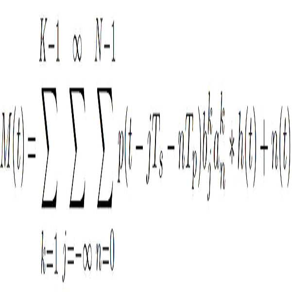
여기서, K는 시스템 내에 존재하는 활성화된 사용자(active user)의 총 수이고, n(t)는 가산성 백색 가우시안 잡음(additive white Gaussian noise)이다.Here, K is the total number of active users present in the system, and n (t) is additive white Gaussian noise.
수신기(520)가 바람직한 사용자(즉, 0번째 사용자)의 예상 지연(expected delay) 및 확산 코드(spreading code)에 대한 정보를 가지고 있다고 가정할 때, 바람직한 사용자를 제외한 나머지 모든 사용자들(즉, 1번째 사용자부터 K-1번째 사용자) 각각의 신호는 수신기(520) 관점에서는 장애로 간주된다. 그 결과, 수신기(520)에서 수신되는 신호 파형은 수학식 6과 같이 표현될 수 있다.Assuming that the
![]()
![]()
여기서, S0(t)는 바람직한 사용자에 의해 전송되는 신호이고, h0(t)는 S0(t)에 대응되는 채널 임펄스 응답이다.Here, S 0 (t) is a signal transmitted by a preferred user, and h 0 (t) is a channel impulse response corresponding to S 0 (t).
바람직한 사용자에 의해 전송되는 신호 S0(t)는 비트 전송 오율(bit error rate: BER)을 구하기 위하여 원래의 신호 템플릿에 코릴레이션(correlation)된다.The signal S 0 (t) transmitted by the preferred user is correlated to the original signal template to obtain a bit error rate (BER).
도 6은 본 실시예에 따른 나노네트워크 통신장치에 의사랜덤 이진 코드(pseudo-random binary code: PRN)를 적용하여 시뮬레이션한 결과를 나타낸 그래프이고, 도 7은 본 실시예에 따른 나노네트워크 통신장치에 시뮬레이티드 어닐링 코드(simulated annealing code: SA)를 적용하여 시뮬레이션한 결과를 나타낸 그래프이다.6 is a graph showing a simulation result by applying a pseudo-random binary code (PRN) to a nanonetwork communication apparatus according to this embodiment, and FIG. 7 is a nanonetwork communication apparatus according to this embodiment It is a graph showing the results of simulation by applying a simulated annealing code (SA).
도 6 및 도 7에서, 시뮬레이션 파라미터는 표 1에 나타낸 바와 같다.6 and 7, simulation parameters are as shown in Table 1.
도 6 및 도 7에서는, BER에 대한 심볼에너지대잡음비(symbol-energy-to noise ratio: SNR)(Es/N0)를 이용하여 시뮬레이션 결과를 평가하였다. 시뮬레이션에는 동일한 길이를 갖는 두 가지 유형의 코드 즉, PRN 코드 및 SA 코드가 사용되었다. 채널의 수증기 분자의 농도는 10 %이며, 간섭을 일으키는 사용자의 숫자는 2에서 15로 설정하였다. 사용자들 사이의 거리는 10 μm에서 1 m까지 균일하게 변경하였다. 송신기(510-1, 510-2, ..., 510-N)와 수신기(520)는 완전히 동기화되고, 여러 사용자가 불규칙적으로 데이터를 송수신한다고 가정하였다. 여러 사용자들 사이의 오프셋 간격은 0과 Tp(N-1) 사이에서 선택된 특정 값이다.6 and 7, simulation results were evaluated using a symbol-energy-to noise ratio (SNR) (E s / N 0 ) for BER. Two types of codes having the same length, PRN code and SA code, were used in the simulation. The concentration of water molecules in the channel is 10%, and the number of users causing interference was set from 2 to 15. The distance between users was uniformly changed from 10 μm to 1 m. It is assumed that the transmitters 510-1, 510-2, ..., 510-N and the
도 5 내지 도 7을 참조하면, SNR이 낮은 영역(SNR < 5 dB)에서는 PRN 코드 및 SA 코드의 성능이 별다른 차이를 보이지 않는 것으로 확인된다. 이는 테라헤르츠 대역의 높은 확산 손실에 기인한다. 이에 따라 수신기(520)는 바람직한 신호를 구별하지 못한다. 그러나, SNR이 증가하면 증가할수록, 식별이 가능한 차이점이 발견된다. 사용자의 숫자가 큰 경우 즉, 송신기의 개수가 많은 경우, 수신기(520)에서의 간섭도 더욱 크다. 또한, 이 영역의 높은 채널 손실 때문에 간섭을 발생시키는 사용자의 숫자가 작음에도 불구하고 원하는 BER을 얻기 위해서는 높은 SNR이 요구된다. SNR이 5 dB보다 큰 영역에서는, PNR 코드를 사용하는 것이 SA 코드를 사용하는 것보다 더욱 좋은 성능을 나타냄을 확인할 수 있다.5 to 7, it is confirmed that the performance of the PRN code and the SA code does not show a significant difference in a region with a low SNR (SNR <5 dB). This is due to the high spreading loss in the terahertz band. Accordingly, the
도 8은 본 실시예에 따른 나노네트워크 통신장치에 의사랜덤 이진 코드(pseudo-random binary code: PRN) 및 시뮬레이티드 어닐링 코드(simulated annealing code: SA)를 적용한 경우에 있어서 성능 비교 결과를 나타낸 그래프이다.FIG. 8 is a graph showing performance comparison results when a pseudo-random binary code (PRN) and a simulated annealing code (SA) are applied to a nanonetwork communication device according to the present embodiment. to be.
도 8의 그래프는, 심볼에너지대잡음비(Es/N0)를 25 dB로 고정한 경우에 있어, 서로 다른 두 가지 코드를 적용함에 따른 나노네트워크 통신장치의 성능을 나타낸다.The graph of FIG. 8 shows the performance of the nanonetwork communication apparatus by applying two different codes when the symbol energy-to-noise ratio (Es / N0) is fixed to 25 dB.
PRN 코드가 모든 사용자 숫자에 대해 SA 코드보다 나은 성능을 나타내었다. 이것은 PRN 코드의 크로스 코릴레이션(cross-correlation) 특성이 SA 코드의 크로스 코릴레이션 특성보다 좋기 때문이다.The PRN code performed better than the SA code for all user numbers. This is because the cross-correlation property of the PRN code is better than that of the SA code.
크로스 코릴레이션 특성이 낮은 코드일수록 다중접속 장애를 최소화하기에 적합하다. 크로스 코릴레이션 특성을 평가하기 위해 사용된 판단기준은 피크 크로스 코릴레이션 레벨(peak cross-correlation level: PCCL)로서, PRN 코드의 PCCL은 -5.22 dB를 나타낸 반면, SA 코드의 PCCL은 -4.25 dB인 것으로 확인되었다. PRN 코드의 낮은 PCCL 특성 덕분에 PRN 코드의 BER 특성이 SA 코드의 BER 특성보다 좋게 나타난 것을 확인할 수 있다.Codes with a low cross correlation characteristic are suitable for minimizing multiple access failures. The criterion used to evaluate the cross correlation characteristic is a peak cross-correlation level (PCCL), where the PCCL of the PRN code represents -5.22 dB, whereas the PCCL of the SA code is -4.25 dB. Was confirmed. It can be seen that the BER characteristic of the PRN code is better than the BER characteristic of the SA code due to the low PCCL characteristic of the PRN code.
도 9는 본 실시예에 따른 나노네트워크 통신방법을 나타낸 흐름도이다.9 is a flowchart illustrating a nanonetwork communication method according to the present embodiment.
본 실시예에 따른 나노네트워크 통신장치에 대해서는 도 2 내지 도 8을 참조하여 상세하게 설명하였으므로, 이와 중복되는 내용에 대한 설명은 생략하거나 간략히 하기로 한다.Since the nano-network communication apparatus according to the present embodiment has been described in detail with reference to FIGS. 2 to 8, descriptions of the overlapped contents will be omitted or simplified.
도 5 및 도 9를 참조하면, 단계 S910에서, 복수의 송신기(510-1 내지 510-N) 각각은, 기 설정된 펄스 지속시간(pulse duration)과 기 설정된 듀티 사이클(duty cycle)을 갖는 펄스를 생성한다. 여기서, 펄스의 주파수는 0.1 THz부터 10 THz 사이의 주파수를 가질 수 있다. 생성된 펄스 p(t)는 수백 펨토초(femtosecond)의 펄스-폭(pulse-width)을 갖는 가우시안 모노사이클 펄스(Gaussian monocycle pulse)일 수 있으며, 전술한 수학식 1과 같이 표현될 수 있다.5 and 9, in step S910, each of the plurality of transmitters 510-1 to 510-N has a pulse having a preset pulse duration and a preset duty cycle. To create. Here, the frequency of the pulse may have a frequency between 0.1 THz and 10 THz. The generated pulse p (t) may be a Gaussian monocycle pulse having a pulse-width of several hundred femtoseconds, and may be expressed as Equation 1 described above.
단계 S920에서, 복수의 송신기(510-1 내지 510-N) 각각은 변조 신호의 생성에 이용되는 특정 코드, 예컨대 확산 코드(spreading code)를 생성한다. 이 때, 생성되는 특정 코드는 송신기(즉, 사용자) 별로 서로 다르므로, 수신기는 복수의 송신기로부터 송출된 신호를 구별할 수 있게 된다. 또한, 확산 코드는 의사랜덤 이진 코드(pseudo-random binary code: PRN) 및 시뮬레이티드 어닐링 코드(simulated annealing code: SA)를 포함할 수 있다.In step S920, each of the plurality of transmitters 510-1 to 510-N generates a specific code used for generating a modulated signal, for example, a spreading code. At this time, since the specific codes generated are different for each transmitter (that is, the user), the receiver can distinguish signals transmitted from a plurality of transmitters. Further, the spreading code may include a pseudo-random binary code (PRN) and a simulated annealing code (SA).
단계 S930에서, 복수의 송신기(510-1 내지 510-N) 각각은, 단계 S910에서 생성된 펄스 및 사용자 데이터에 기반하여 직접 확산 방식의 온-오프 변조(direct sequence on-off keying: DS-OOK)를 수행하여 변조신호를 생성한다.In step S930, each of the plurality of transmitters 510-1 to 510-N, direct sequence on-off keying: DS-OOK based on the pulse and user data generated in step S910. ) To generate a modulated signal.
단계 S940에서, 복수의 송신기(510-1 내지 510-N) 각각은, 송신 안테나를 이용하여, 단계 S930에서 생성된 변조신호를 테라헤르츠 대역(Terahertz band) 채널을 통해 송출할 수 있다.In step S940, each of the plurality of transmitters 510-1 to 510-N may transmit a modulated signal generated in step S930 through a terahertz band channel using a transmission antenna.
이 경우, 수신기(520)는 송출된 변조신호들을 수신한 후, 각 신호의 변조에 이용된 특정 코드와 동일한 코드를 이용하여 각 신호를 복조함으로써 사용자 데이터를 복원할 수 있게 된다.In this case, the
도 9에서는 각각의 과정을 순차적으로 실행하는 것으로 기재하고 있으나, 반드시 이에 한정되는 것은 아니다. 다시 말해, 도 9에 기재된 과정을 변경하여 실행하거나 하나 이상의 과정을 병렬적으로 실행하는 것으로 적용 가능할 것이므로, 도 9는 시계열적인 순서로 한정되는 것은 아니다.Although FIG. 9 describes that each process is executed sequentially, the present invention is not limited thereto. In other words, since the process described in FIG. 9 may be changed or executed or one or more processes may be executed in parallel, FIG. 9 is not limited to a time series sequence.
한편, 도 9에 도시된 흐름도의 각 단계는 컴퓨터로 읽을 수 있는 기록매체(computer-readable recording medium)에 컴퓨터가 읽을 수 있는 코드로서 구현하는 것이 가능하다. 컴퓨터가 읽을 수 있는 기록매체는 컴퓨터 시스템에 의하여 읽혀질 수 있는 데이터가 저장되는 모든 종류의 기록장치를 포함한다. 즉, 컴퓨터가 읽을 수 있는 기록매체는 마그네틱 저장매체(예를 들면, 롬, 플로피 디스크, 하드디스크 등), 광학적 판독 매체(예를 들면, 시디롬, 디브이디 등) 및 캐리어 웨이브(예를 들면, 인터넷을 통한 전송)와 같은 저장매체를 포함한다. 또한, 컴퓨터가 읽을 수 있는 기록매체는 네트워크로 연결된 컴퓨터 시스템에 분산되어 분산방식으로 컴퓨터가 읽을 수 있는 코드가 저장되고 실행될 수 있다.On the other hand, each step of the flow chart shown in Figure 9 can be implemented as computer-readable code in a computer-readable recording medium. The computer-readable recording medium includes all kinds of recording devices in which data readable by a computer system is stored. That is, the computer-readable recording medium includes magnetic storage media (eg, ROM, floppy disk, hard disk, etc.), optical reading media (eg, CD-ROM, DVD, etc.) and carrier waves (eg, the Internet). Storage). In addition, the computer-readable recording medium can be distributed over network coupled computer systems so that the computer readable code is stored and executed in a distributed fashion.
이상의 설명은 본 발명에 따른 실시예들의 기술 사상을 예시적으로 설명한 것에 불과한 것으로서, 본 발명에 따른 실시예들이 속하는 기술 분야에서 통상의 지식을 가진 자라면 본 실시예들의 본질적인 특성에서 벗어나지 않는 범위에서 다양한 수정 및 변형이 가능할 것이다. 따라서, 본 발명에 따른 실시예들은 본 실시예들의 기술 사상을 한정하기 위한 것이 아니라 설명하기 위한 것이고, 이러한 실시예들에 의하여 본 실시예들의 기술 사상의 범위가 한정되는 것은 아니다. 본 발명에 따른 실시예들의 보호 범위는 아래의 청구범위에 의하여 해석되어야 하며, 그와 동등한 범위 내에 있는 모든 기술 사상은 본 발명에 따른 실시예들의 권리범위에 포함되는 것으로 해석되어야 할 것이다.The above description is merely illustrative of the technical spirit of the embodiments according to the present invention, and those of ordinary skill in the art to which the embodiments according to the present invention belong do not depart from the essential characteristics of the present embodiments Various modifications and variations will be possible. Therefore, the embodiments according to the present invention are not intended to limit the technical spirit of the present embodiments, but to explain, and the scope of the technical spirit of the present embodiments is not limited by these embodiments. The scope of protection of the embodiments according to the present invention should be interpreted by the following claims, and all technical spirits within the equivalent range should be interpreted as being included in the scope of the embodiments according to the present invention.
100, 200, 400, 500: 나노네트워크 통신장치
110, 210, 410, 510-1, 510-2, 510-N: 송신기
112, 212, 412: 펄스 발생기 114, 214, 414: 변조기
115: 타이밍 정보 생성기 215, 415: 코드정보 생성기
116, 216, 416: 송신 안테나
120, 220, 420, 520: 수신기
122, 222, 422: 수신 안테나 124: 검출기
224, 424: RF 프론트엔드 225, 425: 위상 검출기
226, 426: 대역통과필터 126, 228, 428 : 복조기
229, 429: 코드정보 생성기100, 200, 400, 500: nano network communication device
110, 210, 410, 510-1, 510-2, 510-N: transmitter
112, 212, 412:
115: timing
116, 216, 416: transmit antenna
120, 220, 420, 520: receiver
122, 222, 422: receiving antenna 124: detector
224, 424: RF front end 225, 425: phase detector
226, 426:
229, 429: Code information generator
Claims (9)
기설정된 듀티 사이클을 갖는 펄스를 생성하는 펄스 발생기, 상기 생성된 펄스와 사용자 데이터에 대해 확산 코드(spreading code)를 이용한 DS-OOK 변조를 수행하여 변조신호를 생성하는 변조기, 및 상기 변조신호를 테라헤르츠 대역 채널을 통해 송출하는 송신 안테나를 포함하는 송신기; 및
상기 송출된 변조신호를 상기 확산 코드와 동일한 코드를 이용하여 복조하는 수신기를 포함하되,
상기 수신기는,
예상 지연(expected delay) 및 확산 코드(spreading code) 정보가 알려진 특정 송신기를 제외한 나머지 송신기로부터 수신되는 신호를 장애로 간주하는,
나노네트워크 통신장치.As a terahertz band based nano network communication device,
A pulse generator that generates a pulse having a predetermined duty cycle, a modulator that generates a modulated signal by performing DS-OOK modulation using a spreading code on the generated pulse and user data, and tera the modulated signal A transmitter including a transmit antenna transmitting through a Hertz band channel; And
It includes a receiver for demodulating the transmitted modulation signal using the same code as the spreading code,
The receiver,
A signal received from a transmitter other than a specific transmitter whose predicted delay and spreading code information is known is regarded as a failure,
Nano network communication device.
상기 듀티 사이클은,
펄스 지속시간 및 심볼 지속시간에 기초하여 산출되는,
나노네트워크 통신장치.According to claim 1,
The duty cycle,
Calculated based on the pulse duration and symbol duration,
Nano network communication device.
상기 변조기는,
상기 펄스 발생기에 의해 생성된 펄스가 존재하는 경우 제1 데이터 비트를 할당하고,
상기 펄스 발생기에 의해 생성된 펄스가 존재하지 않는 경우 제2 데이터 비트를 할당하는,
나노네트워크 통신장치.According to claim 1,
The modulator,
If there is a pulse generated by the pulse generator, allocate a first data bit,
Allocating a second data bit when the pulse generated by the pulse generator does not exist,
Nano network communication device.
상기 변조기는,
상기 확산 코드를 생성하는 코드정보 생성기를 포함하는,
나노네트워크 통신장치.According to claim 1,
The modulator,
Including the code information generator for generating the spreading code,
Nano network communication device.
상기 확산 코드는,
의사랜덤 이진 코드(pseudo-random binary code: PRN)인,
나노네트워크 통신장치.According to claim 1,
The spreading code,
Pseudo-random binary code (PRN),
Nano network communication device.
상기 생성된 펄스는,
수백 펨토초(femtosecond)의 펄스-폭(pulse-width)을 갖는 가우시안 모노사이클 펄스(Gaussian monocycle pulse)인,
나노네트워크 통신장치.According to claim 1,
The generated pulse,
A Gaussian monocycle pulse with pulse-width of hundreds of femtoseconds,
Nano network communication device.
상기 생성된 펄스는,
0.1 내지 10 THz의 주파수(frequency)를 갖는,
나노네트워크 통신장치.According to claim 1,
The generated pulse,
Having a frequency of 0.1 to 10 THz,
Nano network communication device.
기설정된 듀티 사이클을 갖는 펄스를 생성하는 단계;
상기 생성된 펄스 및 사용자 데이터에 대해 확산 코드(spreading code)를 이용한 DS-OOK 변조를 수행하여 변조신호를 생성하는 단계; 및
상기 생성된 변조신호를 테라헤르츠 대역 채널을 통해 송출하는 단계를 포함하되,
상기 송출된 변조신호는 상기 확산 코드와 동일한 코드를 이용하여 복조되고,
예상 지연(expected delay) 및 확산 코드(spreading code) 정보가 알려진 특정 송신기를 제외한 나머지 송신기로부터 송출되는 신호는 장애로 간주되는,
나노네트워크 통신방법.Terahertz band-based nano-network communication method,
Generating a pulse having a predetermined duty cycle;
Generating a modulated signal by performing DS-OOK modulation using a spreading code on the generated pulse and user data; And
And transmitting the generated modulated signal through a terahertz band channel.
The transmitted modulated signal is demodulated using the same code as the spreading code,
Signals transmitted from other transmitters except for specific transmitters for which predicted delay and spreading code information are known are considered as failures.
Nano network communication method.
상기 확산 코드는,
의사랜덤 이진 코드(pseudo-random binary code: PRN)인,
나노네트워크 통신방법.The method of claim 8,
The spreading code,
Pseudo-random binary code (PRN),
Nano network communication method.
Priority Applications (1)
| Application Number | Priority Date | Filing Date | Title |
|---|---|---|---|
| KR1020180074596A KR102108825B1 (en) | 2018-06-28 | 2018-06-28 | Apparatus and method for communication in nanonetwork |
Applications Claiming Priority (1)
| Application Number | Priority Date | Filing Date | Title |
|---|---|---|---|
| KR1020180074596A KR102108825B1 (en) | 2018-06-28 | 2018-06-28 | Apparatus and method for communication in nanonetwork |
Publications (2)
| Publication Number | Publication Date |
|---|---|
| KR20200001738A KR20200001738A (en) | 2020-01-07 |
| KR102108825B1 true KR102108825B1 (en) | 2020-05-12 |
Family
ID=69153842
Family Applications (1)
| Application Number | Title | Priority Date | Filing Date |
|---|---|---|---|
| KR1020180074596A Active KR102108825B1 (en) | 2018-06-28 | 2018-06-28 | Apparatus and method for communication in nanonetwork |
Country Status (1)
| Country | Link |
|---|---|
| KR (1) | KR102108825B1 (en) |
Families Citing this family (1)
| Publication number | Priority date | Publication date | Assignee | Title |
|---|---|---|---|---|
| TR2023017844A1 (en) * | 2023-12-20 | 2024-09-23 | Istanbul Medipol Ueniversitesi | AN ON/OFF SWITCHING METHOD IN THE TERAHERTZ BAND |
Citations (2)
| Publication number | Priority date | Publication date | Assignee | Title |
|---|---|---|---|---|
| KR101614653B1 (en) | 2015-03-26 | 2016-04-21 | 인하대학교 산학협력단 | Method and Apparatus for Terahertz EM Hybrid Nano Communication interfacing and Molecular Communication |
| KR101652634B1 (en) | 2015-04-10 | 2016-08-30 | 인하대학교 산학협력단 | Method and Apparatus for Inhibitor-based Modulation for Molecular Communication in Nanonetworks |
-
2018
- 2018-06-28 KR KR1020180074596A patent/KR102108825B1/en active Active
Patent Citations (2)
| Publication number | Priority date | Publication date | Assignee | Title |
|---|---|---|---|---|
| KR101614653B1 (en) | 2015-03-26 | 2016-04-21 | 인하대학교 산학협력단 | Method and Apparatus for Terahertz EM Hybrid Nano Communication interfacing and Molecular Communication |
| KR101652634B1 (en) | 2015-04-10 | 2016-08-30 | 인하대학교 산학협력단 | Method and Apparatus for Inhibitor-based Modulation for Molecular Communication in Nanonetworks |
Non-Patent Citations (2)
| Title |
|---|
| Hakim Mabed, "Enhanced Spread in Time On-Off Keying Technique for Dense Terahertz Nanonetworks", 2017 IEEE Symposium on Computers and Communications (ISCC), 04 September 2017. 1부.* |
| Pankaj Singh. et. al, "TH-PPM with non-coherent detection for multiple access in electromagnetic wireless nanocommunications", researchgate Article in Nano Communication Networks, May 2018. 1부.* |
Also Published As
| Publication number | Publication date |
|---|---|
| KR20200001738A (en) | 2020-01-07 |
Similar Documents
| Publication | Publication Date | Title |
|---|---|---|
| US6611223B2 (en) | Method and apparatus for ultra wide-band communication system using multiple detectors | |
| US20070297543A1 (en) | UWB communication receiver feedback loop | |
| JP2004528776A (en) | Method and apparatus for signal detection in ultra wideband communication | |
| Mesloub et al. | Chip averaging chaotic ON–OFF keying: A new non-coherent modulation for ultra wide band direct chaotic communication | |
| CN100380833C (en) | Ultra-wideband pulse sequence generation device and method, and data communication device and method | |
| US7317748B2 (en) | Methods and apparatus for transmitting and receiving randomly inverted wideband signals | |
| KR102108825B1 (en) | Apparatus and method for communication in nanonetwork | |
| Quyen | On the performance of low-rate wireless correlation-delay-shift-keying system | |
| Ezzeddine et al. | Pulsing the passive RF identification technology: the pulsed wave mode | |
| Rodionov et al. | Application of incoherent multi-frequency signals for information transmission in a nonstationary hydroacoustic environment | |
| Xu et al. | On the nonlinear Teager-Kaiser operator for energy detection based impulse radio UWB receivers | |
| Barras et al. | A robust front-end architecture for low-power UWB radio transceivers | |
| Barras | A low-power impulse radio ultra-wideband CMOS radio-frequency transceiver | |
| CN103647737B (en) | The time hopping modulation implementation method of MPPSK modulation | |
| KR20190016342A (en) | Method and apparatus for improving a detection rate of frequency hopping signals | |
| Kazakov et al. | Radio monitoring of wireless networks using LoRa data transmission technology | |
| Kobayashi et al. | Performance evaluation of the spread spectrum human body communication devices | |
| KR100500166B1 (en) | UWB impulse signal generator | |
| Bilgiç | Aerial acoustic data communication | |
| Hosseini | Multiuser detection in TH-UWB communication systems | |
| Ghendir et al. | Novel M-ary PPM time hopping scheme for UWB communications | |
| Sahukar et al. | A proposal for new millimeter wave wideband transceiver system—The code shifted reference impulse radio system | |
| Rebhi et al. | TH Differential Pseudo-Random Pulse: A New UWB System for LR-WPAN Applications | |
| IVANOU et al. | The basic types of pulse modulation used for ultra-wideband communication systems are considered. The interactions between a modulated signal and additive white Gaussian noise are analyzed. The most noiseproof and optimum types of modulation for practical implementation are defined. The fundamental direction is to increase the channel capacity for wireless telecommunication systems. Data transmission rate is proportional to the width of signal spectrum. So, for example, sufficient channel | |
| Shen et al. | A new time-hopping/direct-sequence biorthogonal PPM UWB communication system |
Legal Events
| Date | Code | Title | Description |
|---|---|---|---|
| A201 | Request for examination | ||
| PA0109 | Patent application |
Patent event code: PA01091R01D Comment text: Patent Application Patent event date: 20180628 |
|
| PA0201 | Request for examination | ||
| E902 | Notification of reason for refusal | ||
| PE0902 | Notice of grounds for rejection |
Comment text: Notification of reason for refusal Patent event date: 20190507 Patent event code: PE09021S01D |
|
| PG1501 | Laying open of application | ||
| E701 | Decision to grant or registration of patent right | ||
| PE0701 | Decision of registration |
Patent event code: PE07011S01D Comment text: Decision to Grant Registration Patent event date: 20200410 |
|
| GRNT | Written decision to grant | ||
| PR0701 | Registration of establishment |
Comment text: Registration of Establishment Patent event date: 20200504 Patent event code: PR07011E01D |
|
| PR1002 | Payment of registration fee |
Payment date: 20200504 End annual number: 3 Start annual number: 1 |
|
| PG1601 | Publication of registration | ||
| PR1001 | Payment of annual fee |
Payment date: 20240327 Start annual number: 5 End annual number: 5 |