KR102087815B1 - Air conditioning system of a motor vehicle and method for operating the air conditioning system - Google Patents
Air conditioning system of a motor vehicle and method for operating the air conditioning system Download PDFInfo
- Publication number
- KR102087815B1 KR102087815B1 KR1020180034806A KR20180034806A KR102087815B1 KR 102087815 B1 KR102087815 B1 KR 102087815B1 KR 1020180034806 A KR1020180034806 A KR 1020180034806A KR 20180034806 A KR20180034806 A KR 20180034806A KR 102087815 B1 KR102087815 B1 KR 102087815B1
- Authority
- KR
- South Korea
- Prior art keywords
- coolant
- air
- heat transfer
- conditioning system
- air conditioning
- Prior art date
- Legal status (The legal status is an assumption and is not a legal conclusion. Google has not performed a legal analysis and makes no representation as to the accuracy of the status listed.)
- Active
Links
Images


Classifications
-
- B—PERFORMING OPERATIONS; TRANSPORTING
- B60—VEHICLES IN GENERAL
- B60H—ARRANGEMENTS OF HEATING, COOLING, VENTILATING OR OTHER AIR-TREATING DEVICES SPECIALLY ADAPTED FOR PASSENGER OR GOODS SPACES OF VEHICLES
- B60H1/00—Heating, cooling or ventilating [HVAC] devices
- B60H1/32—Cooling devices
- B60H1/3204—Cooling devices using compression
- B60H1/3227—Cooling devices using compression characterised by the arrangement or the type of heat exchanger, e.g. condenser, evaporator
-
- B—PERFORMING OPERATIONS; TRANSPORTING
- B60—VEHICLES IN GENERAL
- B60H—ARRANGEMENTS OF HEATING, COOLING, VENTILATING OR OTHER AIR-TREATING DEVICES SPECIALLY ADAPTED FOR PASSENGER OR GOODS SPACES OF VEHICLES
- B60H1/00—Heating, cooling or ventilating [HVAC] devices
- B60H1/00321—Heat exchangers for air-conditioning devices
- B60H1/00335—Heat exchangers for air-conditioning devices of the gas-air type
-
- B—PERFORMING OPERATIONS; TRANSPORTING
- B60—VEHICLES IN GENERAL
- B60H—ARRANGEMENTS OF HEATING, COOLING, VENTILATING OR OTHER AIR-TREATING DEVICES SPECIALLY ADAPTED FOR PASSENGER OR GOODS SPACES OF VEHICLES
- B60H1/00—Heating, cooling or ventilating [HVAC] devices
- B60H1/32—Cooling devices
- B60H1/3204—Cooling devices using compression
- B60H1/3205—Control means therefor
- B60H1/3211—Control means therefor for increasing the efficiency of a vehicle refrigeration cycle
-
- B—PERFORMING OPERATIONS; TRANSPORTING
- B60—VEHICLES IN GENERAL
- B60H—ARRANGEMENTS OF HEATING, COOLING, VENTILATING OR OTHER AIR-TREATING DEVICES SPECIALLY ADAPTED FOR PASSENGER OR GOODS SPACES OF VEHICLES
- B60H1/00—Heating, cooling or ventilating [HVAC] devices
- B60H1/00007—Combined heating, ventilating, or cooling devices
- B60H1/00021—Air flow details of HVAC devices
- B60H1/00028—Constructional lay-out of the devices in the vehicle
-
- B—PERFORMING OPERATIONS; TRANSPORTING
- B60—VEHICLES IN GENERAL
- B60H—ARRANGEMENTS OF HEATING, COOLING, VENTILATING OR OTHER AIR-TREATING DEVICES SPECIALLY ADAPTED FOR PASSENGER OR GOODS SPACES OF VEHICLES
- B60H1/00—Heating, cooling or ventilating [HVAC] devices
- B60H1/00007—Combined heating, ventilating, or cooling devices
- B60H1/00021—Air flow details of HVAC devices
- B60H1/00035—Air flow details of HVAC devices for sending an air stream of uniform temperature into the passenger compartment
- B60H1/00057—Air flow details of HVAC devices for sending an air stream of uniform temperature into the passenger compartment the air being heated and cooled simultaneously, e.g. using parallel heat exchangers
-
- B—PERFORMING OPERATIONS; TRANSPORTING
- B60—VEHICLES IN GENERAL
- B60H—ARRANGEMENTS OF HEATING, COOLING, VENTILATING OR OTHER AIR-TREATING DEVICES SPECIALLY ADAPTED FOR PASSENGER OR GOODS SPACES OF VEHICLES
- B60H1/00—Heating, cooling or ventilating [HVAC] devices
- B60H1/00271—HVAC devices specially adapted for particular vehicle parts or components and being connected to the vehicle HVAC unit
-
- B—PERFORMING OPERATIONS; TRANSPORTING
- B60—VEHICLES IN GENERAL
- B60H—ARRANGEMENTS OF HEATING, COOLING, VENTILATING OR OTHER AIR-TREATING DEVICES SPECIALLY ADAPTED FOR PASSENGER OR GOODS SPACES OF VEHICLES
- B60H1/00—Heating, cooling or ventilating [HVAC] devices
- B60H1/00642—Control systems or circuits; Control members or indication devices for heating, cooling or ventilating devices
- B60H1/00814—Control systems or circuits characterised by their output, for controlling particular components of the heating, cooling or ventilating installation
- B60H1/00878—Control systems or circuits characterised by their output, for controlling particular components of the heating, cooling or ventilating installation the components being temperature regulating devices
- B60H1/00899—Controlling the flow of liquid in a heat pump system
-
- B—PERFORMING OPERATIONS; TRANSPORTING
- B60—VEHICLES IN GENERAL
- B60H—ARRANGEMENTS OF HEATING, COOLING, VENTILATING OR OTHER AIR-TREATING DEVICES SPECIALLY ADAPTED FOR PASSENGER OR GOODS SPACES OF VEHICLES
- B60H1/00—Heating, cooling or ventilating [HVAC] devices
- B60H1/02—Heating, cooling or ventilating [HVAC] devices the heat being derived from the propulsion plant
- B60H1/03—Heating, cooling or ventilating [HVAC] devices the heat being derived from the propulsion plant and from a source other than the propulsion plant
- B60H1/039—Heating, cooling or ventilating [HVAC] devices the heat being derived from the propulsion plant and from a source other than the propulsion plant from air leaving the interior of the vehicle, i.e. heat recovery
-
- B—PERFORMING OPERATIONS; TRANSPORTING
- B60—VEHICLES IN GENERAL
- B60H—ARRANGEMENTS OF HEATING, COOLING, VENTILATING OR OTHER AIR-TREATING DEVICES SPECIALLY ADAPTED FOR PASSENGER OR GOODS SPACES OF VEHICLES
- B60H1/00—Heating, cooling or ventilating [HVAC] devices
- B60H1/32—Cooling devices
- B60H1/3204—Cooling devices using compression
- B60H1/3205—Control means therefor
- B60H1/321—Control means therefor for preventing the freezing of a heat exchanger
-
- B—PERFORMING OPERATIONS; TRANSPORTING
- B60—VEHICLES IN GENERAL
- B60H—ARRANGEMENTS OF HEATING, COOLING, VENTILATING OR OTHER AIR-TREATING DEVICES SPECIALLY ADAPTED FOR PASSENGER OR GOODS SPACES OF VEHICLES
- B60H1/00—Heating, cooling or ventilating [HVAC] devices
- B60H1/32—Cooling devices
- B60H1/3204—Cooling devices using compression
- B60H1/3205—Control means therefor
- B60H1/3213—Control means therefor for increasing the efficiency in a vehicle heat pump
-
- B—PERFORMING OPERATIONS; TRANSPORTING
- B60—VEHICLES IN GENERAL
- B60H—ARRANGEMENTS OF HEATING, COOLING, VENTILATING OR OTHER AIR-TREATING DEVICES SPECIALLY ADAPTED FOR PASSENGER OR GOODS SPACES OF VEHICLES
- B60H1/00—Heating, cooling or ventilating [HVAC] devices
- B60H1/32—Cooling devices
- B60H1/3204—Cooling devices using compression
- B60H1/3228—Cooling devices using compression characterised by refrigerant circuit configurations
- B60H1/32281—Cooling devices using compression characterised by refrigerant circuit configurations comprising a single secondary circuit, e.g. at evaporator or condenser side
-
- B—PERFORMING OPERATIONS; TRANSPORTING
- B60—VEHICLES IN GENERAL
- B60H—ARRANGEMENTS OF HEATING, COOLING, VENTILATING OR OTHER AIR-TREATING DEVICES SPECIALLY ADAPTED FOR PASSENGER OR GOODS SPACES OF VEHICLES
- B60H1/00—Heating, cooling or ventilating [HVAC] devices
- B60H1/32—Cooling devices
- B60H1/3204—Cooling devices using compression
- B60H1/323—Cooling devices using compression characterised by comprising auxiliary or multiple systems, e.g. plurality of evaporators, or by involving auxiliary cooling devices
-
- F25B41/003—
-
- F25B41/046—
-
- F—MECHANICAL ENGINEERING; LIGHTING; HEATING; WEAPONS; BLASTING
- F25—REFRIGERATION OR COOLING; COMBINED HEATING AND REFRIGERATION SYSTEMS; HEAT PUMP SYSTEMS; MANUFACTURE OR STORAGE OF ICE; LIQUEFACTION SOLIDIFICATION OF GASES
- F25B—REFRIGERATION MACHINES, PLANTS OR SYSTEMS; COMBINED HEATING AND REFRIGERATION SYSTEMS; HEAT PUMP SYSTEMS
- F25B43/00—Arrangements for separating or purifying gases or liquids; Arrangements for vaporising the residuum of liquid refrigerant, e.g. by heat
-
- B—PERFORMING OPERATIONS; TRANSPORTING
- B60—VEHICLES IN GENERAL
- B60H—ARRANGEMENTS OF HEATING, COOLING, VENTILATING OR OTHER AIR-TREATING DEVICES SPECIALLY ADAPTED FOR PASSENGER OR GOODS SPACES OF VEHICLES
- B60H1/00—Heating, cooling or ventilating [HVAC] devices
- B60H1/00007—Combined heating, ventilating, or cooling devices
- B60H1/00021—Air flow details of HVAC devices
- B60H2001/00078—Assembling, manufacturing or layout details
- B60H2001/00085—Assembling, manufacturing or layout details of air intake
-
- B—PERFORMING OPERATIONS; TRANSPORTING
- B60—VEHICLES IN GENERAL
- B60H—ARRANGEMENTS OF HEATING, COOLING, VENTILATING OR OTHER AIR-TREATING DEVICES SPECIALLY ADAPTED FOR PASSENGER OR GOODS SPACES OF VEHICLES
- B60H1/00—Heating, cooling or ventilating [HVAC] devices
- B60H1/00007—Combined heating, ventilating, or cooling devices
- B60H1/00021—Air flow details of HVAC devices
- B60H2001/00078—Assembling, manufacturing or layout details
- B60H2001/00092—Assembling, manufacturing or layout details of air deflecting or air directing means inside the device
-
- B—PERFORMING OPERATIONS; TRANSPORTING
- B60—VEHICLES IN GENERAL
- B60H—ARRANGEMENTS OF HEATING, COOLING, VENTILATING OR OTHER AIR-TREATING DEVICES SPECIALLY ADAPTED FOR PASSENGER OR GOODS SPACES OF VEHICLES
- B60H1/00—Heating, cooling or ventilating [HVAC] devices
- B60H1/00007—Combined heating, ventilating, or cooling devices
- B60H1/00021—Air flow details of HVAC devices
- B60H2001/0015—Temperature regulation
- B60H2001/00178—Temperature regulation comprising an air passage from the HVAC box to the exterior of the cabin
-
- B—PERFORMING OPERATIONS; TRANSPORTING
- B60—VEHICLES IN GENERAL
- B60H—ARRANGEMENTS OF HEATING, COOLING, VENTILATING OR OTHER AIR-TREATING DEVICES SPECIALLY ADAPTED FOR PASSENGER OR GOODS SPACES OF VEHICLES
- B60H1/00—Heating, cooling or ventilating [HVAC] devices
- B60H1/00642—Control systems or circuits; Control members or indication devices for heating, cooling or ventilating devices
- B60H1/00814—Control systems or circuits characterised by their output, for controlling particular components of the heating, cooling or ventilating installation
- B60H1/00878—Control systems or circuits characterised by their output, for controlling particular components of the heating, cooling or ventilating installation the components being temperature regulating devices
- B60H2001/00928—Control systems or circuits characterised by their output, for controlling particular components of the heating, cooling or ventilating installation the components being temperature regulating devices comprising a secondary circuit
Landscapes
- Engineering & Computer Science (AREA)
- Physics & Mathematics (AREA)
- Thermal Sciences (AREA)
- Mechanical Engineering (AREA)
- Chemical & Material Sciences (AREA)
- Combustion & Propulsion (AREA)
- Air-Conditioning For Vehicles (AREA)
- Analytical Chemistry (AREA)
- Power Engineering (AREA)
- General Engineering & Computer Science (AREA)
Abstract
본 발명은 냉각제 회로(2a, 2b, 2c, 2d, 2f)와 냉각수 회로(30a, 30e, 30g)를 구비한 자동차의 공조 시스템(1a, 1b, 1c, 1d, 1e, 1f, 1g)에 관한 것이다. 상기 냉각제 회로(2a, 2b, 2c, 2d, 2f)는 압축기(3), 냉각수 회로(30a, 30e, 30g)의 냉각수와 냉각제 사이의 열전달을 위해 응축기/기체냉각기로서 작동할 수 있는 냉각제-냉각수-열전달기(4), 제1 팽창기(5)뿐만 아니라, 승객 공간을 위한 공급 공기의 공기 조절을 위한 제1 냉각제-공기-열전달기(6)를 포함한다. 상기 냉각수 회로(30a, 30e, 30g)는 이송 장치(31), 승객 공간을 위한 공급 공기의 가열을 위한 제1 냉각수-공기-열전달기(33), 제2 냉각수-공기-열전달기(37)뿐만 아니라, 냉각제-냉각수-열전달기(4)를 구비하여 형성된다. 또한, 냉각제 회로(2a, 2b, 2c, 2d, 2f)는 오로지 기화기로서만 작동할 수 있는 제2 냉각제-공기-열전달기(9)를 포함하고, 이때 냉각제의 유동 방향으로 제2 냉각제-공기-열전달기(9)의 상류에는 제2 팽창기(8)가 위치하며, 제2 팽창기(8)뿐만 아니라 제2 냉각제-공기-열전달기(9)는 제1 유동 경로 내(12)에 배치된다.
또한, 본 발명은 공조 시스템의 작동 방법에 관한 것이다.The present invention relates to an air conditioning system (1a, 1b, 1c, 1d, 1e, 1f, 1g) of a vehicle having a coolant circuit (2a, 2b, 2c, 2d, 2f) and a coolant circuit (30a, 30e, 30g) will be. The coolant circuit (2a, 2b, 2c, 2d, 2f) is a coolant-coolant that can act as a condenser / gas cooler for heat transfer between the coolant and coolant of the compressor (3), coolant circuit (30a, 30e, 30g) -Includes a heat transfer (4), a first expander (5), as well as a first coolant-air-heat transfer (6) for air conditioning of the supply air for the passenger space. The cooling water circuits 30a, 30e, 30g include a transfer device 31, a first cooling water-air-heat transfer device 33 for heating supply air for a passenger space, and a second cooling water-air-heat transfer device 37 In addition, it is formed with a coolant-coolant-heat transfer (4). Further, the coolant circuits 2a, 2b, 2c, 2d, 2f include a second coolant-air-heat transfer unit 9 that can only operate as a vaporizer, wherein the second coolant-air in the direction of flow of the coolant -Upstream of the heat transfer (9) is located a second expander (8), the second expander (8) as well as the second coolant-air-heat transfer (9) is disposed in the first flow path (12) .
Further, the present invention relates to a method of operating an air conditioning system.
Description
본 발명은 냉각제 회로와 냉각수 회로를 구비한, 자동차의 승객 공간의 공기를 조절하기 위한 공조 시스템에 관한 것이다. 냉각제 회로는 압축기, 냉각수 회로의 냉각수와 냉각제 사이의 열전달을 위해 응축기/기체냉각기로서 작동할 수 있는 냉각제-냉각수-열전달기, 제1 팽창기뿐만 아니라, 승객 공간을 위한 공급 공기의 공기 조절을 위한 제1 냉각제-공기-열전달기를 포함한다. 냉각수 회로는 냉각수의 순환을 위한 이송 장치, 승객 공간을 위한 공급 공기의 가열을 위한 제1 냉각수-공기-열전달기, 제2 냉각수-공기-열전달기뿐만 아니라, 냉각제-냉각수-열전달기를 구비하여 형성된다.The present invention relates to an air conditioning system for controlling air in a passenger space of a vehicle, provided with a coolant circuit and a coolant circuit. The coolant circuit is a compressor, a coolant-coolant-heat transfer device that can act as a condenser / gas cooler for heat transfer between coolant and coolant in the coolant circuit, as well as a first expander, as well as a control agent for air conditioning of the supply air for the passenger space. 1 Includes coolant-air-heat transfer. The coolant circuit is formed by providing a conveying device for circulating the coolant, a first coolant-air-heat transfer device for heating the supply air for the passenger space, a second coolant-air-heat transfer device, as well as a coolant-coolant-heat transfer device do.
또한, 본 발명은 공조 시스템의 작동 방법에 관한 것이다.In addition, the present invention relates to a method of operating an air conditioning system.
종래 기술에 공지된 자동차의 경우, 승객 공간을 위한 공급 공기를 가열하기 위해 엔진의 폐열이 사용된다. 이러한 폐열은 엔진 냉각수 회로에서 순환하는 냉각수에 의해 공조 설비 쪽으로 전달되어 그곳에서 히터 열전달기를 통해 승객 공간 내로 유입 유동하는 공기에 전달된다. 차량 구동부의 효율적인 연소 엔진의 냉각수 회로로부터 가열 성능에 관계하는 냉각수-공기-열전달기를 구비한 공지된 장치는, 주변 온도가 낮을 경우 승객 공간의 전체적인 가열 요구를 충족시키기 위한 승객 공간의 쾌적한 가온에 필요한 수준에는 더이상 도달하지 못한다. 하이브리드 구동을 사용하는 자동차, 다시 말해 전기 모터식 구동뿐만 아니라 연소 엔진식 구동을 사용하는 자동차 내의 공조 설비에 대해서도 유사하게 적용된다.In the case of automobiles known in the prior art, the waste heat of the engine is used to heat the supply air for the passenger space. The waste heat is transferred to the air conditioning equipment by cooling water circulating in the engine cooling water circuit, where it is transferred to the air flowing into the passenger space through the heater heat transfer. Known devices equipped with coolant-air-heat transfers that relate to heating performance from the cooling water circuit of an efficient combustion engine in the vehicle drive are required for comfortable heating of the passenger space to meet the overall heating needs of the passenger space when the ambient temperature is low. The level is no longer reached. The same applies to automobiles using hybrid driving, ie electric motor-driven as well as air conditioning equipment in automobiles using combustion engine-driven.
승객 공간의 전체적인 가열 수요가 엔진의 냉각수 회로로부터의 가열에 의해 충족될 수 없는 경우, 예를 들어 영어 약자로 PTC("Positive Temperatur Coefficient-Thermistor")라 지칭되는 전기 저항 히터 또는 연료 히터와 같은 추가의 가열 조치가 필요하다. 순수하게 전기 모터에 의해서만 구동되는 자동차 또는 연료 전지 차량 내의 공조 설비에 대해서도 동일하게 적용된다. 승객 공간을 위한 공기를 가열하기에 더 효율적으로 가능한 수단은 열원으로서 공기를 이용하는 가열 펌프이며, 이 경우 냉각제 회로는 유일한 가열 수단일뿐만 아니라 추가 가열 조치로서도 사용된다.If the overall heating demand of the passenger space cannot be met by heating from the engine's coolant circuit, for example, an additional such as an electric resistance heater or fuel heater, abbreviated as PTC ("Positive Temperatur Coefficient-Thermistor") in English. Heating action is required. The same applies to air conditioning equipment in automobiles or fuel cell vehicles driven purely by electric motors. A more efficient means of heating air for the passenger space is a heat pump that uses air as a heat source, in which case the coolant circuit is not only the only heating means but also used as an additional heating measure.
전기 저항 히터가 하류에 연결된 공조 시스템은 한편으로 비용 효율적으로 제조될 수 있고 임의의 자동차에 사용될 수 있지만, 매우 큰 전기 에너지의 수요를 포함하는데, 그 이유는 냉각제 회로의 기화기의 과류 중에 승객 공간을 위한 공급 공기가 우선 냉각되고/냉각되거나 제습된 다음에, 이어서 공급 공기 또는 냉각수 회로에 열을 직접 전달하는 전기 저항에 의해 가열되기 때문이다.An air conditioning system in which an electric resistance heater is connected downstream can, on the one hand, be produced cost-effectively and used in any vehicle, but it involves a very large demand for electrical energy, because it occupies the passenger space during the overflow of the carburetor of the coolant circuit. This is because the supply air for cooling is first cooled and / or dehumidified and then heated by an electrical resistance that directly transfers heat to the supply air or coolant circuit.
가열 펌프로서 작동하는 종래의 공조 시스템의 작동은 실제로 효율적이긴 하지만, 공조 시스템을 위한 구조 공간이 전혀 확보되지 않은 자동차의 내부에 위치시키는 데에도 매우 큰 구조 공간을 필요로 한다. 특히, 제조와 유지 보수의 비용이 상승하는 것뿐만 아니라 큰 구조 공간을 필요로 하는 것도 방해가 된다.Although the operation of a conventional air conditioning system operating as a heat pump is actually efficient, it also requires a very large structural space to be positioned inside a vehicle where no structural space for the air conditioning system is secured. In particular, not only is the cost of manufacturing and maintenance rising, but also the need for large structural spaces is a hindrance.
조합된 냉각 설비 모드와 가열 펌프 모드를 위해, 다시 말해 가열 모드뿐만 아니라 재가열-작동으로도 지칭되는 후속 가열 모드를 위해 형성되어 있는, 종래 기술에 속하는 공기-공기-가열 펌프는 주변 공기로부터 열을 흡수한다. 따라서, 주변 공기는 냉각제의 기화를 위한 열원으로서 사용된다. 종래의 공기-공기-가열 펌프는 냉각제와 주변 사이의 열전달을 위한 열전달기, 승객 공간의 조절될 공기의 열을 냉각제에 공급하기 위한 열전달기, 및 냉각제로부터 승객 공간을 위한 조절될 공기에 열을 전달하기 위한 열전달기를 포함한다. 성능은 각각 냉각제와 공기 사이에 전달된다.An air-air-heating pump belonging to the prior art, which is formed for the combined cooling plant mode and the heating pump mode, that is to say for the heating mode as well as the subsequent heating mode, also referred to as reheating-operation, is an air-air-heating pump of the prior art. Absorb. Therefore, ambient air is used as a heat source for vaporization of the coolant. Conventional air-air-heating pumps provide heat transfer for heat transfer between the coolant and the surroundings, heat transfer to supply heat of the air to be regulated in the passenger space to the coolant, and heat from the coolant to the air to be controlled for the passenger space. Includes heat transfer for delivery. Performance is transferred between coolant and air, respectively.
소위 "재가열" 또는 후속 가열 모드에서 승객 공간에 공급될 공기가 냉각되고, 이 경우 제습된 다음, 이어서 약간 다시 가열된다. 이러한 작동 모드에서는 필요한 후속 가열 성능이 공기의 냉각 및 제습을 위해 필요한 냉각 성능보다 더 낮다.In the so-called "reheat" or subsequent heating mode, the air to be supplied to the passenger space is cooled, in this case dehumidified and then heated again slightly. In this mode of operation, the required subsequent heating performance is lower than that required for cooling and dehumidifying air.
이 경우, 냉각제와 공기-공기-가열 펌프의 주변 공기 사이에 열을 전달하기 위한 열전달기는 자동차의 전방 측에서 공조 시스템의 하우징 외부에, 구체적으로는 공조 장치의 외부에 배치되고, 특히 주행 바람을 통해 공기의 작용을 받는다. 공조 장치의 하우징 외부에 배치된 열전달기는 주변 열전달기로도 지칭된다.In this case, a heat transfer device for transferring heat between the coolant and the ambient air of the air-air-heating pump is disposed outside the housing of the air conditioning system, specifically outside the air conditioning system, on the front side of the vehicle, in particular driving wind Through the action of air. A heat transfer device disposed outside the housing of the air conditioning device is also referred to as a peripheral heat transfer device.
냉각 설비 모드에서 냉각제 회로의 작동 중에는 주변 열전달기가 응축기/기체냉각기로서 냉각제로부터 주변 공기에 열을 제공하기 위해 작동되고, 가열 펌프 모드에서 냉각제 회로의 작동 중에는 기화기로서 주변 공기로부터 냉각제에 의해 열을 흡수하기 위해 작동된다. 따라서, 주변 열전달기는 두 가지 기능으로 작동하기 위해 설계되지만, 결과적으로 이러한 설계는 두 기능 중 어느 하나에 대해서도 최적으로 설계되지 않는다.During the operation of the coolant circuit in the cooling plant mode, the ambient heat transfer is operated to provide heat from the coolant to the ambient air as a condenser / gas cooler, and during the operation of the coolant circuit in the heat pump mode, the heat is absorbed by the coolant from the ambient air as a vaporizer. To work. Thus, the ambient heat transfer is designed to work with two functions, but as a result, this design is not optimally designed for either function.
예를 들어 냉각제 R134a를 사용하는 것과 같은 냉각제 회로의 임계에 미달하는 작동 중에 또는 이산화탄소를 갖는 특정 주변 조건에서 냉각제가 액상인 경우, 열전달기는 응축기로 지칭된다. 열전달의 일부는 일정한 온도에서 발생한다. 열전달기에서 임계를 초과하는 작동 또는 임계를 초과하는 열전달의 경우, 냉각제의 온도는 지속적으로 감소한다. 이러한 경우에 열전달기는 기체냉각기로도 지칭된다. 임계를 초과하는 작동은 특정 주변 조건이나 냉각제 회로의 작동 방식에서 예를 들어 이산화탄소 냉각제를 사용하여 발생할 수 있다.A heat transfer is referred to as a condenser when the coolant is liquid during certain subcritical conditions with carbon dioxide or during subcritical operation of the coolant circuit, such as using coolant R134a. Part of the heat transfer occurs at a constant temperature. In the case of operation exceeding the threshold in the heat transfer or heat transfer exceeding the threshold, the temperature of the coolant is continuously decreased. The heat transfer in this case is also referred to as a gas cooler. Operation above the threshold can occur, for example, using carbon dioxide coolants in certain ambient conditions or in the way the coolant circuit works.
DE 10 2012 111 672 A1호에는 자동차의 승객 공간의 공기를 조절하기 위한 공조 설비의 냉각제 회로가 기재되어 있다. 냉각제 회로는 냉각 설비 모드와 가열 펌프 모드에서 조합된 작동을 위해 그리고 후속 가열 모드를 위해 형성되고, 압축기, 냉각제와 주변 사이에 열을 전달하기 위한 열전달기, 제1 팽창기뿐만 아니라, 승객 공간의 조절될 공기의 열을 냉각제에 공급하기 위한 열전달기, 냉각제로부터 승객 공간을 위해 조절될 공기에 열을 전달하기 위한 열전달기, 그리고 냉각제의 유동 방향으로 이에 이어지는 제2 팽창기를 포함한다.DE 10 2012 111 672 A1 describes a coolant circuit in an air conditioning system for controlling the air in the passenger space of a motor vehicle. The coolant circuit is formed for combined operation in the cooling plant mode and the heat pump mode and for the subsequent heating mode, the compressor, the heat transfer device for transferring heat between the coolant and the surroundings, as well as the regulation of the passenger space. It includes a heat transfer unit for supplying heat of air to be supplied to the coolant, a heat transfer unit for transferring heat from the coolant to the air to be regulated for the passenger space, and a second expander leading to the flow direction of the coolant.
냉각제 회로는 연결 라인으로부터 분기된 시스템을 포함하는데, 상기 시스템은 기존의 구조 공간내에 통합되기가 어렵다. 또한, 저압 수준으로 배치되고 큰 용적으로 설계된 냉각제 저장기 및 추가의 밸브는 각각 큰 구조 공간을 필요로 한다. 또한, 밸브는 매우 높은 내부 밀도를 가지며, 이는 또한 시스템 비용의 상승을 초래한다.The coolant circuit includes a system branched from the connecting line, which is difficult to integrate into the existing structural space. In addition, coolant reservoirs arranged at low pressure levels and designed for large volumes and additional valves each require large structural space. In addition, the valve has a very high internal density, which also leads to an increase in system cost.
DE 10 2012 108 891 A1에는, 공기의 안내를 위한 2개의 유동 채널을 구비한 하우징뿐만 아니라, 기화기 및 응축기를 갖는 냉각제 회로를 포함하는, 승객 공간의 공기를 조절하기 위한 공조 시스템이 기재되어 있다. 이 경우 기화기는 제1 유동 채널에 배치되고 응축기는 제2 유동 채널에 배치된다. 공조 시스템은 승객 공간을 냉각시키고 가열하기 위해 그리고 후속 가열 작동을 위해 형성된다. 작동 모드의 설정은 단지 공기 안내 장치의 제어에 의해 이루어질 수 있으므로, 상이한 작동 모드들 사이의 전환을 위한 냉각제-전환 밸브가 생략될 수 있다.DE 10 2012 108 891 A1 describes an air conditioning system for regulating the air in a passenger space, including a housing with two flow channels for guiding air, as well as a coolant circuit with a vaporizer and a condenser. In this case the vaporizer is placed in the first flow channel and the condenser is placed in the second flow channel. An air conditioning system is formed for cooling and heating the passenger space and for subsequent heating operations. Since the setting of the operating mode can only be made by control of the air guiding device, a coolant-switching valve for switching between different operating modes can be omitted.
각각의 작동 모드와는 무관하게, 공조 시스템의 기화기 측과 응축기 측을 위해 각각 하나의 송풍기가 제공되어, 이로써 별도로 작동할 수 있는 두 개의 송풍기가 제공될 수 있다. 이 경우, 예를 들어 냉각 설비 모드에서 작동 중에 주행 바람의 에너지는 응축기 측에서 열 방출을 위해 사용되지 않는다. 해당 송풍기는 항상 작동 상태에 있고, 이는 진동 및 소음을 유발할 수 있다. 또한, 공조기를 위한 구조 공간이 전혀 확보되지 않은 자동차의 내부에서 위치들을 위한 구조 공간의 확보가 필요하다.Regardless of each operating mode, one blower is provided for each of the carburetor side and the condenser side of the air conditioning system, whereby two blowers which can be operated separately can be provided. In this case, for example, the energy of the running wind during operation in the cooling plant mode is not used for heat dissipation on the condenser side. The blower is always in operation, which can cause vibration and noise. In addition, it is necessary to secure the structural space for the positions in the interior of the car where the structural space for the air conditioner is not secured at all.
도 1에는 종래 기술에서 냉각제 회로(2') 및 냉각수 회로(30')를 구비한 공조 시스템(1')이 도시되어 있다. 냉각제 회로(2')는 냉각제의 유동 방향으로 압축기(3), 응축기/기체냉각기로서 작동하는 냉각제-냉각수-열전달기(4), 팽창기(5)뿐만 아니라, 기화기로서 작동하는 냉각제-공기-열전달기(6)를 포함한다. 압축기(3)는 기화기(6)로부터 냉각제를 흡입한다. 냉각제 회로(1')는 폐쇄되어 있다.1 shows an air conditioning system 1 'having a coolant circuit 2' and a coolant circuit 30 'in the prior art. The coolant circuit 2 'is composed of a
냉각제 회로(1')는 또한 내부 열전달기(7)도 구비하여 형성될 수 있다. 내부 열전달기(7)는 회로 내부의 열전달기로 이해되어야 하며, 이 열전달기는 고압의 냉각제와 저압의 냉각제 사이의 열전달에 사용된다. 이 경우, 예를 들어 한편으로는 액체 냉각제가 응축 이후에 다시 냉각되고, 다른 한편으로는 흡입 기체가 기화기(3) 이전에 과열된다.The coolant circuit 1 'can also be formed with an internal heat transfer 7. The internal heat transfer 7 should be understood as a heat transfer inside the circuit, which is used for heat transfer between a high pressure coolant and a low pressure coolant. In this case, for example, the liquid coolant on the one hand is cooled again after condensation, and on the other hand the intake gas is superheated before the
냉각수 회로(30')는 냉각수의 순환을 위한 이송 장치(31), 특히 펌프, 냉각수의 가열을 위한 추가-가열 열전달기(32), 구체적으로는 전기 저항 히터(PTC)뿐만 아니라, 승객 공간에 대한 공급 공기의 가열을 위한 제1 냉각수-공기-열전달기로서 가열 열전달기(33)를 포함한다. 가열 열전달기(33)는 냉각제-냉각수-열전달기(4)와 연결된다. 냉각수 회로(30')는 폐쇄되어 있다. 냉각제 측에서 응축기/기체냉각기로서 작동하는 냉각제-냉각수-열전달기(4)는 결과적으로 냉각수에 의해 냉각된다.The
또한, 가열 열전달기(33)와 냉각제-냉각수-열전달기(4) 사이에 형성된 연결 라인에는 분기 위치로서 3방향 밸브(34a)뿐만 아니라 합류 위치(35)가 제공되며, 이들 사이에는 각각, 공기에 열을 전달하기 위한 제2 냉각수-공기-열전달기(37)를 구비한 제1 유동 경로(36a)뿐만 아니라 상기 냉각수-공기-열전달기(37)를 우회하는 바이패스로서 제2 유동 경로(38)가 형성된다. 제2 냉각수-공기-열전달기(37)는 설비 모듈(52)의 내부에 배치되고 유동 방향(53)으로 공기의 작용을 받는다.In addition, the connecting line formed between the heating
냉각제 회로(2') 중 기화기로서 작동하는 냉각제-공기-열전달기(6)와, 냉각수 회로(30')의 가열 열전달기(33)는 공조 장치(50)의 내부에 그리고 승객 공간의 공급 공기의 유동 방향(51)으로 서로 차례로 작용을 받을 수 있게 배치된다. 이로써 기화기(6)의 과류중에 냉각된 그리고/또는 제습된 공급 공기는 필요에 따라 가열 열전달기(33)의 과류중에 가열될 수 있다.Of the coolant circuit 2 ', the coolant-air-
가열 열전달기(33)에서 승객 공간의 공급 공기에 전달될 수 있는 열은, 공급 공기의 충분한 온도에 도달하기 위해, 냉각제-냉각수-열전달기(4)에서 총합으로 냉각수에 전달되는 에너지로서 기화기(6) 및 압축기(3) 내에서 냉각제에 전달되는 에너지와, 추가-가열 열전달기(32)에서 냉각수에 전달되는 열로부터 합산된다.The heat that can be transferred to the supply air in the passenger space in the heating
공조 시스템(1')은 기화기(6)에 유입 유동되는 공급 공기의 온도가 0℃를 초과하는 온도값인 경우에만 작동될 수 있다. 0℃ 미만의 온도값인 경우에는 추가-가열 열전달기(32), 특히 전기 저항 히터를 통해 가열 성능이 결정되므로 이로써 비효율적으로 제공된다. 0℃의 범위 및 0℃ 미만인 공기의 온도에서 기화기(6)의 열전달 표면은 동결될 수 있다. 공기로부터 열을 흡수한 결과로서, 냉각된 공기의 상대 공기 습도가 상승한다. 이슬점 온도에 미달하게 되면, 공기 중에 존재하는 수증기는 응축되고 열전달 표면에 물로서 침착된다. 이 경우, 열전달 표면에서 공기로부터 응축된 물은 표면 온도가 0℃ 및 0℃ 미만인 경우 얼음으로 고착된다. 얼음 층이 증가되면 공기측의 열전달 표면 및 공기측의 열전달이 감소하므로, 결과적으로 공기와 기화된 냉각제 사이의 열전달이 감소한다.The air conditioning system 1 'can be operated only when the temperature of the supply air flowing into the
이제, 본 발명의 과제는 냉각 설비 모드 및 가열 펌프 모드에서뿐만 아니라 후속 가열 모드에서도 작동될 수 있는 자동차용 공조 시스템을 제공하는 것이다. 이 경우, 주변 공기는 각각의 작동 모드에 따라, 예를 들어 가열 펌프 모드에서의 작동 중에 열원으로서뿐만 아니라, 예를 들어 냉각 설비 모드에서의 작동 중에 히트 싱크로서도 사용되어야 한다. 주변 공기로부터 열을 흡수하기 위한 열전달기는 최적으로 설계되어야 한다.It is now an object of the present invention to provide an air conditioning system for an automobile which can be operated in a cooling installation mode and a heating pump mode as well as in a subsequent heating mode. In this case, the ambient air must be used according to each operating mode, for example as a heat source during operation in the heat pump mode, as well as as a heat sink during operation in the cooling plant mode, for example. A heat transfer device for absorbing heat from ambient air must be optimally designed.
또한, 공조 시스템은, 예를 들어 공기에 의한 열전달을 위해 냉각제 회로의 기화기의 동결 위험이 최소화되어 효율적으로 작동될 수 있고 콤팩트하게 구현되어야 한다. 이 경우 공조 시스템의 냉각제 회로는, 단지 최소의 작동 비용, 제조 비용 및 유지 보수 비용을 유발할뿐만 아니라 최소의 구조 공간을 포함하기 위해, 구조적으로 간단하게 구성되어야 하고 필요한 수의 구성 부품을 최소로 포함해야 한다. In addition, the air conditioning system must be implemented in a compact manner and can be operated efficiently with minimal risk of freezing of the carburetor of the coolant circuit, for example for heat transfer by air. In this case, the coolant circuit of the air conditioning system should be structurally simple and include the minimum number of components necessary to include not only minimal operating cost, manufacturing cost and maintenance cost, but also minimal structural space. Should be.
또한, 본 발명의 과제는, 상이하거나 동일한 압력 수준에서 복수의 열전달기가 작동될 수 있는 공조 시스템의 작동 방법을 제공하는 것이다.Further, an object of the present invention is to provide a method of operating an air conditioning system in which a plurality of heat transfer units can be operated at different or equal pressure levels.
이러한 과제는 특허청구범위의 독립항의 특징을 갖는 대상 또는 방법에 의해 해결된다. 추가의 개선예는 종속항에 기재된다.This problem is solved by an object or method having the characteristics of the independent claims of the claims. Further improvements are described in the dependent claims.
상기 과제는, 특히 냉각 설비 모드에서, 가열 펌프 모드에서뿐만 아니라, 후속 가열 모드에서 작동을 위해 냉각제 회로와 냉각수 회로를 구비한, 자동차의 승객 공간의 공기를 조절하기 위한 본 발명에 따른 공조 시스템에 의해 해결된다. 냉각제 회로는 냉각제의 유동 방향으로 압축기, 냉각수 회로의 냉각수와 냉각제 사이의 열전달을 위해 응축기/기체냉각기로서 작동할 수 있는 냉각제-냉각수-열전달기, 제1 팽창기뿐만 아니라, 승객 공간을 위한 공급 공기의 공기 조절을 위한 제1 냉각제-공기-열전달기를 포함한다. 냉각수 회로는 냉각수의 순환을 위한 이송 장치, 승객 공간을 위한 공급 공기의 가열을 위한 제1 냉각수-공기-열전달기, 제2 냉각수-공기-열전달기뿐만 아니라, 냉각제-냉각수-열전달기를 구비하여 형성된다.The above object is achieved by the air conditioning system according to the present invention for controlling the air in the passenger space of a motor vehicle, particularly with a coolant circuit and a coolant circuit for operation in a cooling installation mode, not only in a heating pump mode, but also in a subsequent heating mode. Is solved. The coolant circuit is a coolant-coolant-heat transfer device that can act as a condenser / gas cooler for heat transfer between the coolant and coolant in the coolant circuit in the direction of flow of coolant, as well as the first expander, as well as the supply air for the passenger space. And a first coolant-air-heat transfer for air conditioning. The coolant circuit is formed by providing a conveying device for circulating the coolant, a first coolant-air-heat transfer device for heating the supply air for the passenger space, a second coolant-air-heat transfer device, as well as a coolant-coolant-heat transfer device do.
냉각 설비 모드는 무엇보다도 냉각에 사용되고, 가열 펌프 모드는 가열에 사용되며, 후속 가열 모드는 조절할 승객 공간의 공급 공기의 후속 가열에 사용된다. 후속 가열 모드의 경우, 공급 공기는 후속 가열 이전에 냉각되고/냉각되거나 제습되었다.The cooling installation mode is used for cooling, among other things, the heating pump mode is used for heating, and the subsequent heating mode is used for subsequent heating of the supply air in the passenger space to be regulated. For subsequent heating modes, the feed air was cooled and / or dehumidified prior to subsequent heating.
본 발명의 컨셉에 따르면, 냉각제 회로는 오로지 기화기로서만 작동할 수 있는 제2 냉각제-공기-열전달기를 구비하여 형성된다. 이 경우, 냉각제의 유동 방향으로 제2 냉각제-공기-열전달기의 상류에는 제2 팽창기가 위치한다. 제2 팽창기뿐만 아니라 제2 냉각제-공기-열전달기는 공동으로 제1 유동 경로 내에 배치된다.According to the concept of the invention, the coolant circuit is formed with a second coolant-air-heat transfer which can only act as a vaporizer. In this case, a second expander is located upstream of the second coolant-air-heat transfer in the flow direction of the coolant. The second cooler-air-heat transfer as well as the second expander are jointly disposed within the first flow path.
냉각수 회로의 제2 냉각수-공기-열전달기 및 냉각제 회로의 제2 냉각제-공기-열전달기는 유리하게 설비 모듈 내부에 그리고 공기의 유동 방향으로 위에서 언급된 순서로 서로 차례로 공기의 작용을 받을 수 있게 배치된다.The second coolant-air-heat transfer of the coolant circuit and the second coolant-air-heat transfer of the coolant circuit are advantageously able to receive the action of air in turn in the order mentioned above in the installation module and in the direction of air flow. Is placed.
본 발명의 일 개선예에 따르면, 특히 자동차의 전방 영역에 배치된 설비 모듈은 승객 공간으로부터 배출되는 공기, 또는 주변 공기, 또는 승객 공간으로부터 배출되는 공기와 주변 공기로 이루어진 혼합 공기에 의해 관류 가능하게 형성된다.According to one improvement of the present invention, in particular, the facility module disposed in the front area of the vehicle enables perfusion by air discharged from the passenger space, or ambient air, or mixed air composed of air and ambient air discharged from the passenger space. Is formed.
본 발명의 제1 대안 실시예에 따르면, 제1 냉각제-공기-열전달기 및 제2 냉각제-공기-열전달기는 냉각제 회로 내에서 서로에 대해 직렬로 관류 가능하게 배치된다.According to a first alternative embodiment of the present invention, the first coolant-air-heat transfer and the second coolant-air-heat transfer are arranged to be flowable in series with respect to each other in the coolant circuit.
유리하게 냉각제 회로는 밸브를 구비한 제2 유동 경로를 포함한다. 이 경우 제1 유동 경로는 제2 팽창기뿐만 아니라 제2 냉각제-공기-열전달기를 구비하여 연장되고, 제2 유동 경로는 각각 분기 위치로부터 합류 위치까지 연장됨으로써, 결과적으로 제2 유동 경로는 제1 유동 경로에 대해 평행한 바이패스로서 형성된다.The coolant circuit advantageously comprises a second flow path with a valve. In this case, the first flow path extends with a second expander as well as a second coolant-air-heat transfer, and the second flow paths each extend from a branching position to a confluence position, resulting in the second flow path being a first flow It is formed as a bypass parallel to the path.
본 발명의 제2 대안 실시예에 따르면, 제1 냉각제-공기-열전달기와 제2 냉각제-공기-열전달기는 냉각제 회로 내에서 서로에 대해 병렬로 관류 가능하게 배치된다. According to a second alternative embodiment of the present invention, the first coolant-air-heat transfer and the second coolant-air-heat transfer are arranged to be flowable in parallel to each other in the coolant circuit.
본 발명의 추가의 장점은, 제2 팽창기 및 제2 냉각제-공기-열전달기를 구비한 제1 유동 경로가 분기 위치로부터 합류 위치까지 연장된다는 데에 있다. 이 경우, 제1 팽창기, 제1 냉각제-공기-열전달기, 및 제3 팽창기는 제2 유동 경로 내에 형성된다. 제3 팽창기는 냉각제-공기-열전달기의 하류에 배치된다. 제2 유동 경로는 마찬가지로 분기 위치로부터 합류 위치까지 연장되도록 형성된다.A further advantage of the present invention is that the first flow path with the second inflator and the second coolant-air-heat transfer extends from the branching position to the confluence position. In this case, the first expander, the first coolant-air-heat transfer, and the third expander are formed in the second flow path. The third expander is disposed downstream of the coolant-air-heat transfer. The second flow path is likewise formed to extend from the branch position to the confluence position.
냉각제 회로는 또한 바람직하게, 기화기로서 작동할 수 있는 하나 이상의 추가 열전달기뿐만 아니라, 이 열전달기의 상류에 배치된 제4 팽창기를 포함하고, 이들은 제3 유동 경로 내에 형성된다. 이 경우, 제3 유동 경로는 분기 위치로부터 합류 위치까지 연장되므로, 결과적으로 제1 유동 경로와 제2 유동 경로와 제3 유동 경로, 그리고 이와 함께 제1 냉각제-공기-열전달기와 제2 냉각제-공기-열전달기와 기화기로서 작동할 수 있는 상기 추가 열전달기는 각각 서로에 대해 병렬로 배치된다. The coolant circuit also preferably includes one or more additional heat transfers that can act as vaporizers, as well as a fourth expander disposed upstream of the heat transfers, which are formed in the third flow path. In this case, the third flow path extends from the branching position to the confluence position, and consequently, the first flow path, the second flow path and the third flow path, together with the first coolant-air-heat transfer and second coolant- The additional heat transfers, which can act as air-heat transfers and vaporizers, are each arranged in parallel to each other.
기화기로서 작동할 수 있고 제3 유동 경로 내에 배치된 상기 추가 열전달기는 유리하게 냉각제-냉각수-열전달기로서 형성된다.The additional heat transfer which can act as a vaporizer and is arranged in the third flow path is advantageously formed as a coolant-coolant-heat transfer.
본 발명의 일 개선예에 따르면, 냉각제 회로 내에서 냉각제의 유동 방향으로 압축기의 전방에 냉각제 저장기로서 수집기가 배치된다. 본 발명의 이에 대한 대안 실시예에 따르면, 냉각제 회로의 냉각제-냉각수-열전달기의 내부에는 냉각제 저장기로서 수집기가 통합되어 형성된다.According to an improvement of the invention, a collector is arranged as a coolant reservoir in the front of the compressor in the direction of flow of coolant in the coolant circuit. According to an alternative embodiment of the present invention, the collector is formed as a coolant reservoir in the interior of the coolant-coolant-heat transfer unit of the coolant circuit.
본 발명의 제1 대안 실시예에 따르면, 냉각수 회로는 승객 공간을 위한 공급 공기의 가열을 위한 제1 냉각수-공기-열전달기와 냉각제-냉각수-열전달기 사이에 형성되어 있는 분기 위치 및 합류 위치를 포함한다. 이 경우, 분기 위치와 합류 위치 사이에는 각각, 제2 냉각수-공기-열전달기를 구비한 제1 유동 경로와, 제2 냉각수-공기-열전달기를 우회하는 바이패스로서 제2 유동 경로가 연장된다. 따라서, 승객 공간을 위한 공급 공기를 가열하기 위한 제1 냉각수-공기-열전달기와 제2 냉각수-공기-열전달기는 서로에 대해 직렬로 냉각수에 의해 관류 가능하게 배치된다.According to a first alternative embodiment of the present invention, the coolant circuit is configured to determine the branch position and confluence position formed between the first coolant-air-heat transfer and coolant-coolant-heat transfer for heating the supply air for the passenger space. Includes. In this case, between the branching position and the joining position, the first flow path with the second coolant-air-heat transfer and the second flow path as bypass bypassing the second coolant-air-heat transfer are respectively extended. Thus, the first coolant-air-heat transfer and the second coolant-air-heat transfer for heating the supply air for the passenger space are arranged to be flowable by the coolant in series with respect to each other.
본 발명의 제2 대안 실시예에 따르면, 냉각수 회로는 분기 위치 및 합류 위치를 포함하고, 이 경우 분기 위치는 승객 공간을 위한 공급 공기를 가열하기 위해 이송 장치와 제1 냉각수-공기-열전달기 사이에 형성되고, 합류 위치는 제1 냉각수-공기-열전달기와 냉각제-냉각수-열전달기 사이에 형성된다. 이 경우, 제2 냉각수-공기-열전달기는 제1 유동 경로 내에 형성되고, 제1 냉각수-공기-열전달기는 승객 공간을 위한 공급 공기를 가열하기 위해 제2 유동 경로 내에 형성된다. 제1 유동 경로 및 제2 유동 경로는 각각 분기 위치로부터 합류 위치까지 연장됨으로써, 결과적으로 제1 냉각수-공기-열전달기와 제2 냉각수-공기-열전달기는 서로에 대해 병렬로 냉각수에 의해 관류 가능하게 배치된다.According to a second alternative embodiment of the invention, the cooling water circuit comprises a branching position and a joining position, in which case the branching position is between the transfer device and the first coolant-air-heat transfer unit for heating the supply air for the passenger space. And the confluence position is formed between the first coolant-air-heat transfer and the coolant-coolant-heat transfer. In this case, a second coolant-air-heat transfer is formed in the first flow path, and a first coolant-air-heat transfer is formed in the second flow path to heat the supply air for the passenger space. The first flow path and the second flow path are each extended from the branch position to the confluence position, and consequently, the first coolant-air-heat transfer and the second coolant-air-heat transfer can flow through the coolant in parallel to each other. Is placed.
분기 위치는 바람직하게 각각 3방향 밸브로서 형성된다.The branch positions are preferably formed as three-way valves, respectively.
냉각제 회로는 유리하게 내부 열전달기를 포함한다.The coolant circuit advantageously includes an internal heat transfer.
또한, 본 발명의 과제는 냉각 설비 모드에서, 가열 펌프 모드에서, 그리고 조절할 승객 공간의 공급 공기를 위한 후속 가열 모드에서 냉각제 회로와 냉각수 회로를 구비한 자동차의 공조 시스템을 작동하기 위한 본 발명에 따른 방법에 의해 해결된다.In addition, the object of the present invention is according to the invention for operating the air conditioning system of an automobile with a coolant circuit and a coolant circuit in a cooling installation mode, in a heating pump mode, and in a subsequent heating mode for supply air in the passenger space to be adjusted. It is solved by the method.
본 발명의 컨셉에 따르면, 냉각제 회로 중 오로지 기화기로서만 작동할 수 있는 제2 냉각제-공기-열전달기에 의해 공기의 열이 냉각제에 전달된다. 이 경우, 제2 냉각제-공기-열전달기 내부에서 냉각제의 압력 수준은, 제2 냉각제-공기-열전달기 내부에서 냉각제의 압력 수준이 제1 냉각제-공기-열전달기의 내부에서의 압력 수준에 상응하거나 제1 냉각제-공기-열전달기 내부에서의 냉각제의 압력 수준보다 더 낮은 방식으로 설정된다.According to the concept of the invention, the heat of the air is transferred to the coolant by a second coolant-air-heat transfer which can only act as a vaporizer in the coolant circuit. In this case, the pressure level of the coolant inside the second coolant-air-heat transfer, the pressure level of the coolant inside the second coolant-air-heat transfer corresponds to the pressure level inside the first coolant-air-heat transfer Or in a manner lower than the pressure level of the coolant inside the first coolant-air-heat transfer.
본 발명의 일 개선예에 따르면, 냉각제 회로의 제1 냉각제-공기-열전달기 및 제2 냉각제-공기-열전달기는 서로에 대해 직렬로 또는 서로에 대해 병렬로 냉각제에 의해 관류된다.According to one refinement of the invention, the first coolant-air-heat transfer and second coolant-air-heat transfer of the coolant circuit are perfused by coolants in series with each other or in parallel with each other.
본 발명의 바람직한 일 실시예에 따르면, 냉각수 회로의 제1 냉각수-공기-열전달기 및 제2 냉각수-공기-열전달기는 서로에 대해 직렬로 또는 서로에 대해 병렬로 냉각수에 의해 관류된다.According to one preferred embodiment of the present invention, the first coolant-air-heat transfer and second coolant-air-heat transfer of the coolant circuit are perfused by coolant in series with each other or in parallel with each other.
바람직하게, 공기의 유동 방향으로 제2 냉각수-공기-열전달기 및 이에 이어서 제2 냉각제-공기-열전달기는 공기의 작용을 받는다.Preferably, the second coolant-air-heat transfer in the direction of flow of air and then the second coolant-air-heat transfer is subjected to the action of air.
본 발명에 따른 공조 시스템의 다양한 장점은 다음과 같이 요약된다:The various advantages of the air conditioning system according to the invention are summarized as follows:
- 승객 공간의 가열을 위한 폐열의 유동을 사용함으로써 최소 에너지를 사용하여 승객 공간을 위한 공급 공기의 공기 조절, 특히 냉각, 제습 및/또는 가열이 이루어지고,-By using the flow of waste heat for heating the passenger space, air conditioning of the supply air for the passenger space using minimal energy is achieved, in particular cooling, dehumidification and / or heating,
- 특히 낮은 외부 온도에서 주변으로부터 열을 흡수하기 위해 가열 펌프 모드에서 작동하는 경우에 사용하기 위한, 기화기로서의 작동을 위해 특별히 형성된 냉각제-공기-열전달기가 사용되며, 이때 더 높은 외부 온도 및 냉방이 필요한 경우 열이 냉각제-공기-열전달기와는 상이한 구성 부품을 통해 주변으로 방출되며, 이 경우, 냉각제 측의 최소 압력 손실 및 공기로부터의 최대 열 흡수뿐만 아니라, 열전달 표면의 최소 동결 위험이 이루어지며,-Coolant-air-heat transfer specially formed for operation as a vaporizer is used, especially for use when operating in a heat pump mode to absorb heat from the surroundings at low external temperatures, where higher external temperatures and cooling are required In this case, heat is released to the surroundings through components different from the coolant-air-heat transfer, in which case a minimum pressure loss on the coolant side and maximum heat absorption from the air, as well as a minimum risk of freezing of the heat transfer surface are achieved,
- 성능, 효율 및 사용 수명이 증가할뿐만 아니라,-Not only increases performance, efficiency and service life,
- 승객 공간 내부에 충분한 쾌적감이 제공되는데, 이는-Sufficient comfort is provided inside the passenger space, which
- 기존의 자동차의 공지된 구조와 제공되어 있는 구조 공간에서 사용하기 위해 통합될 수 있고 최소 구조 공간, 최소 중량 및 최소 구성부품 수를 포함하는 구조적으로 간단한 냉각제 회로를 사용하며, 이를 통해-Uses a structurally simple coolant circuit that can be integrated for use in known structures of existing vehicles and provided structural spaces and includes a minimum structural space, minimum weight and minimum number of components, through which
- 최소 작동 비용, 제조 비용 및 유지 보수 비용이 이루어진다.-Minimum operating cost, manufacturing cost and maintenance cost are achieved.
본 발명의 실시예의 다른 추가의 세부 사항, 및 장점은 해당 도면을 참조로 하기의 실시예의 설명으로부터 제시된다. 도면에는 각각, 제1 및 제2 냉각제-공기-열전달기를 포함하는 냉각제 회로와, 제1 및 제2 냉각수-공기-열전달기를 포함하는 냉각수 회로와, 냉각제 회로 및 냉각수 회로를 열적으로 연결하는 냉각제-냉각수-열전달기를 구비한 공조 시스템이 도시된다.Other further details, and advantages, of the embodiments of the present invention are set forth in the description of the following embodiments with reference to the drawings. In the figure, the coolant circuit including the first and second coolant-air-heat transfer, the coolant circuit including the first and second coolant-air-heat transfer, and the coolant circuit thermally connecting the coolant circuit and the coolant circuit, respectively, are shown in the figure. An air conditioning system with a coolant-heat transfer is shown.
도 1은 종래 기술에 따른 냉각제 회로와 냉각수 회로를 구비한 공조 시스템을 도시한다.
도 2는 서로에 대해 직렬로 배치된 냉각제-공기-열전달기들을 구비한 냉각제 회로를 도시한다.
도 3은 내부 열전달기를 구비한 도 2의 냉각제 회로를 도시한다.
도 4는 서로에 대해 병렬로 배치된 냉각제-공기-열전달기들을 구비한 냉각제 회로를 도시한다.
도 5는 내부 열전달기를 구비한 도 4의 냉각제 회로를 도시한다.
도 6은 도 3의 냉각제 회로 및 열을 회수하기 위해 추가의 열원을 연결하기 위한 추가 열전달기를 구비한 냉각수 회로를 도시한다.
도 7은 열을 회수하기 위해 추가의 열원을 연결하기 위한 추가의, 특히 기화기로서 작용하는 열전달기를 구비한 도 5의 냉각제 회로를 도시한다.
도 8은 도 5의 냉각제 회로뿐만 아니라 냉각제-공기-열전달기의 배치가 변경된 냉각수 회로를 도시한다.1 shows an air conditioning system having a coolant circuit and a coolant circuit according to the prior art.
2 shows a coolant circuit with coolant-air-heat transfers arranged in series with respect to each other.
FIG. 3 shows the coolant circuit of FIG. 2 with an internal heat transfer.
4 shows a coolant circuit with coolant-air-heat transfers arranged in parallel to each other.
FIG. 5 shows the coolant circuit of FIG. 4 with an internal heat transfer.
FIG. 6 shows the coolant circuit of FIG. 3 and a coolant circuit with an additional heat transfer to connect additional heat sources to recover heat.
FIG. 7 shows the coolant circuit of FIG. 5 with an additional, in particular heat transfer acting as a vaporizer, for connecting additional heat sources to recover heat.
FIG. 8 shows the coolant circuit of FIG. 5 as well as the coolant circuit in which the arrangement of coolant-air-heat transfer is changed.
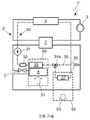
도 2에는 냉각제 회로(2a)와 냉각수 회로(30a)를 구비한 공조 시스템(1a)이 도시되어 있다. 냉각제 회로(2a)는 냉각제의 유동 방향으로 압축기(3), 응축기/기체냉각기로서 작동할 수 있는 냉각제-냉각수-열전달기(4), 제1 팽창기(5), 그리고 승객 공간을 위한 공급 공기의 공기 조절을 위한 제1 냉각제-공기-열전달기(6)를 포함한다. 또한, 냉각제 회로(2a)는 공기의 열을 냉각제에 전달하기 위해 기화기로서 작동하는 제2 냉각제-공기-열전달기(9)를 구비하여 형성되며, 상기 제2 냉각제-공기-열전달기의 상류에는 제2 팽창기(8)가 위치한다. 제1 냉각제-공기-열전달기(6)와 제2 냉각제-공기-열전달기(9)는 서로에 대해 직렬로 또는 차례로 배치된다. 제2 냉각제-공기-열전달기(9)와 이에 할당되는 제2 팽창기(8)는 제1 유동 경로(12) 내에 형성된다. 유리하게, 제2 냉각제-공기-열전달기(9)는, 공기의 작용을 받으면서 응축기/기체냉각기로서 작동하는 종래의 냉각제-공기-열전달기의 구조 공간을 포함한다.2 shows an
제2 냉각제-공기-열전달기(9)와 압축기(3) 사이에는 수집기(11)가 배치된다. 냉각제의 유동 방향으로 압축기(3)의 전방에 그리고 그에 따라 저압측에 배치된 수집기(11)는 어큐뮬레이터로도 지칭되는 것으로서 냉각제 액체의 침착 및 수집에 사용된다. 압축기(3)는 기체 냉각제를 수집기(11)로부터 흡입한다. 냉각제 회로(2a)는 폐쇄되어 있다.A
도시되지 않은 대안 실시예에 따르면, 수집기는 냉각제 저장기로서 냉각제-냉각수-열전달기(4) 내부에 통합되며, 이로써 냉각제의 고압 수준에 배치된다. 이 경우, 저압 수준에 배치된 수집기(11)가 생략될 수 있다. 또한, 냉각제-냉각수-열전달기(4)는 냉각제의 건조를 위한 장치를 구비하여 형성될 수 있다.According to an alternative embodiment not shown, the collector is integrated inside the coolant-coolant-
냉각제 회로(2a)는 제1 유동 경로(12) 이외에 추가로 제2 유동 경로(13)를 포함하며, 상기 제2 유동 경로는 각각 분기 위치(14)로부터 합류 위치(15)까지 연장된다. 제1 유동 경로(12)에 대해, 특히 제2 냉각제-공기-열전달기(9)에 대해 병렬로 형성된 제2 유동 경로(13)는 밸브(16), 특히 차단 밸브(16)를 포함하고 제2 냉각제-공기-열전달기(9)를 우회하여 냉각제의 질량 유동을 안내하기 위한 바이패스로서 사용된다. The
제1 유동 경로(12) 내에는 제2 냉각제-공기-열전달기(9)와 합류 위치(15) 사이에 역류 방지 부재(10), 특히 체크 밸브가 배치된다. 상기 역류 방지 부재(10)는 제2 유동 경로(13)를 통하여 냉각제-공기-열전달기(9)를 우회하여 안내되는 냉각제 질량 유동이 냉각제-공기-열전달기(9) 내로 복귀 유동하는 것을 방지한다.Within the
냉각수 회로(30a)는 냉각수의 유동 방향으로 냉각수의 순환을 위한 이송 장치(31), 특히 펌프뿐만 아니라, 승객 공간을 위한 공급 공기의 가열을 위한 제1 냉각수-공기-열전달기로서 가열 열전달기(33)를 포함한다. 또한, 가열 열전달기(33)는 냉각제-냉각수-열전달기(4)와 연결되어 있다. 냉각수 회로(30a)는 폐쇄되어 있다.The cooling
결국, 냉각제 측에서 응축기/기체냉각기로서 작동하는 냉각제-냉각수-열전달기(4)는 냉각수에 의해 냉각된다.Eventually, the coolant-coolant-
또한, 가열 열전달기(33)와 냉각제-냉각수-열전달기(4) 사이에 형성된 연결 라인에는, 분기 위치로서 3방향 밸브(34a)뿐만 아니라 합류 위치(35)가 제공되어 있고, 이들 사이에는 공기에 열을 전달하기 위한 제2 냉각수-공기-열전달기(37)를 구비한 제1 유동 경로(36a)뿐만 아니라, 냉각수-공기-열전달기(37)를 우회하는 바이패스로서 제2 유동 경로(38)가 각각 형성된다.In addition, the connecting line formed between the heating
제1 냉각수-공기-열전달기(33)로서 가열 열전달기와 제2 냉각수-공기-열전달기(37)는 서로에 대해 직렬로 냉각수에 의해 관류 가능하게 배치된다.The heating heat transfer and the second cooling water-air-heat transfer (37) as the first cooling water-air-heat transfer (33) are arranged to be flowable through the cooling water in series with respect to each other.
냉각수 회로(30a)의 제2 냉각수-공기-열전달기(37) 및 냉각제 회로(2a)의 기화기로서 작동하는 제2 냉각제-공기-열전달기(9)는, 설비 모듈(52) 내에서뿐만 아니라 자동차의 기존의 구조 공간에서 그리고 공기의 유동 방향(53)으로 서로 차례로 작용을 받을 수 있게 배치된다. 이 경우, 자동차의 전방 영역에 배치된 설비 모듈(52)은 승객 공간으로부터 배출된 공기, 주변 공기, 또는 승객 공간으로부터 배출된 공기와 주변 공기의 혼합 공기에 의해 관류될 수 있다. 결국, 공조 시스템(1a)은 승객 공간으로부터 배출된 공기의 잠재적 열과, 마찬가지로 주변으로부터의 열을 열원으로서 사용한다.The second coolant-air-
이 경우, 공기는 우선 냉각수-공기-열전달기(37)를 거치고 이어서 냉각제-공기-열전달기(9)를 거쳐 안내되어, 결과적으로 이들 열전달기(9, 37)의 배치는 종래의 공지된 배치와는 상이한데, 이는 냉각제-공기-열전달기(9)의 열전달 표면의 동결 위험을 더욱 감소시킨다.In this case, the air is first guided through a coolant-air-heat transfer (37) and then through a coolant-air-heat transfer (9), consequently the arrangement of these heat transfers (9, 37) is a conventionally known arrangement. Different from, which further reduces the risk of freezing of the heat transfer surface of the coolant-air-heat transfer (9).
또한, 냉각수-공기-열전달기(37)에 유입되기 위한 공기는 냉각제-공기-열전달기(9)에 유입되기 위해서도 사용된다.In addition, air for flowing into the coolant-air-
냉각제 회로(2a)의 냉각제-공기-열전달기(6) 및 냉각수 회로(30a)의 가열 열전달기(33)는 공조 장치(50) 내부에 배치되고 승객 공간의 공급 공기의 유동 방향(51)으로 서로 차례로 작용을 받을 수 있게 배치된다. 이로써, 기화기(6)의 과류 중에 냉각 및/또는 제습된, 승객 공간을 위한 공급 공기는 필요에 따라 가열 열전달기(33)의 과류 중에 가열될 수 있다. 먼저 냉각제-공기-열전달기(6)의 과류 중에 조절된 공기가 가열 열전달기(33)에 유입되는 것은 도시되지 않은 온도 밸브에 의해 제어될 수 있다.The coolant-air-
냉각제-냉각수-열전달기(4)는 냉각제 회로(2a)를 냉각수 회로(30a)와 열적으로 연결하는 데에 사용된다. 이 경우 냉각제의 열은 냉각수에 전달된다.The coolant-coolant-
공조 시스템(1a)은, 특히 순환 공기에 의한 작동 중에, 다시 말해 열원으로서 승객 공간으로부터 배출된 공기에 의한 작동 중에, 외부 공기 온도 값이 0℃ 미만인 경우에도, 기화기로서 작동하는 냉각제-공기-열전달기(9)의 열전달기 표면이 동결되는 위험이 없이 작동될 수 있다.The
이러한 작동을 보장하기 위해, 공조 장치(50) 내에 배치된 냉각제-공기-열전달기(6)는 중간 압력 수준에서 냉각제에 의해 작동되고 기화기로서 작동된다. 이 경우 기화기 내에 유입되는 공기의 제습 중에 공기로부터 배출되는 잠재적인 열은, 승객 공간을 위한 공급 공기를 원하는 배출 온도로 가열하기 위해, 압축기(3) 내에서 압축 중에 냉각제에 공급되는 성능과 함께 사용된다. 이 경우, 냉각제에 의해 흡수된 상기 열은 냉각수에 의해 냉각된 냉각제-냉각수-열전달기(4)에서 냉각수에 전달되고, 상기 냉각수는 흡수된 열을 가열 열전달기(33)의 관류 중에 공급 공기에 방출한다.To ensure this operation, the coolant-air-
냉각 설비 모드에서 또는 공급 공기의 제습을 위한 후속 가열 모드에서 작동하는 경우, 냉각제에 의해 흡수되고 냉각수에 전달되는 과량의 열은 냉각수 회로(30a)의 제1 유동 경로(36a)를 통해 안내되어, 자동차의 전방 영역 내에서 저온 냉각기로도 지칭되는 제2 냉각수-공기-열전달기(37)에서 공기에 방출된다. 냉각수는 작동 모드와는 무관하게 순환하고 냉각제-냉각수-열전달기(4)의 관류 중에 가열된다.When operating in a cooling installation mode or in a subsequent heating mode for dehumidification of the supply air, excess heat absorbed by the coolant and transferred to the coolant is guided through the
공조 시스템(1a)이 가열 펌프 모드 또는 후속 가열 모드에서 작동하는 경우, 가열 열전달기(33)에서 승객 공간의 공급 공기에 전달될 수 있는 열은, 승객 공간을 위한 공급 공기의 충분한 온도에 도달하기 위해, 기화기로서 작동하는 제1 냉각제-공기-열전달기(6)에서 또는 기화기로서 작동하는 제2 냉각제-공기-열전달기(9)에서 그리고 압축기(3)에서 냉각제에 전달되는 에너지로부터 합산되는데, 상기 에너지는 냉각제-냉각수-열전달기(4)에서 총합으로서 냉각제에 전달된다.When the
이 경우, 오로지 열의 흡수를 위해 그리고 이로써 기화기로서의 작동을 위해 구성된 냉각제-공기-열전달기(9)는 저압 수준에서 냉각제의 작용을 받는다.In this case, the coolant-air-heat transfer (9) configured solely for absorption of heat and thus for operation as a vaporizer is subjected to the action of coolant at a low pressure level.
필요에 따라, 다시 말해 냉각제 회로(2a)에서 승객 공간의 공급 공기의 가열을 위해 제공되는 열이 후속 가열 모드에서의 작동 중에 충분하여 제2 냉각제-공기-열전달기(9)에서 추가의 열 흡수가 전혀 필요하지 않은 경우, 제2 냉각제-공기-열전달기(9)는 냉각제 회로(2a)로부터 차단되어 파이패스에서 제2 유동 경로(13)를 통해 우회할 수 있다. 밸브(16)는 개방되는 반면, 팽창 밸브로서 형성되는 팽창기(8)는 폐쇄된다.If necessary, that is, the heat provided for heating the supply air in the passenger space in the
공조 시스템(1a)이 가열 펌프 모드에서 작동하는 경우, 제2 냉각제-공기-열전달기(9)의 상류에 위치하는 팽창기(8)는, 냉각제의 유입 온도가 공기의, 특히 주변 공기의 온도보다 단지 약간 아래를 차지하는 저압 수준에서 냉각제가 팽창되도록 제어될 수 있다. 저압 수준에 해당되는 온도에서 냉각제는 기화된다.When the
이 경우, 응축기/기체냉각기로서 작동하는 제1 냉각제-공기-열전달기(6)는 중간 압력 수준에서 냉각제의 작용을 받고 필요한 경우 공조 장치(50) 내로 유입되는 승객 공간을 위한 공기를 예열할 수 있다. 냉각수에 의해 작동되는 가열 열전달기(33)의 과류 중에 상기 공급 공기는 추가로 가열된다.In this case, the first coolant-air-heat transfer (6) acting as a condenser / gas cooler is capable of preheating air for the passenger space flowing into the
공급 공기의 2단계 가열은, 팽창과 그에 따른 제2 냉각제-공기-열전달기(9)에서의 기화 이전에, 냉각제의 가능한 엔탈피 편차의 증가에 의해 공조 시스템(1a)의 작동 효율을 향상시킨다.Two-stage heating of the feed air improves the operating efficiency of the
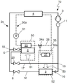
도 3에는 냉각제 회로(2b)와 냉각수 회로(30a)를 구비한 공조 시스템(1b)이 도시되어 있다. 냉각제 회로(2b)는 도 2의 공조 시스템(1a)의 냉각제 회로(2a)와는 상이하게 내부 열전달기(7)를 구비하여 형성된다.3 shows an
내부 열전달기(7)는 고압 측에서 냉각제-냉각수-열전달기(4)와 제1 냉각제-공기-열전달기(6)의 제1 팽창기(5) 사이뿐만 아니라, 저압 측에서 합류 위치(15)와 수집기(11) 또는 압축기(3) 사이에도 형성된다.The internal heat transfer (7) is not only between the coolant-coolant-heat transfer (4) on the high pressure side and the first expander (5) of the first coolant-air-heat transfer (6), but also on the low pressure side (15) And the
이 경우, 내부 열전달기(7)는 고압에서의 냉각제와 저압에서의 냉각제 사이에 열전달을 위해 사용되며, 이때 한편으로는 응축기/기체냉각기로서 작동하는 열전달기(4)로부터 유동하여 배출되는 액체 냉각제가 추가로 냉각되고, 다른 한편으로는 기화기로서 작동하는 열전달기(6, 9)로부터 배출되는 냉각제는 압축기(3) 이전에 흡입 기체로서 과열된다.In this case, the internal heat transfer 7 is used for heat transfer between the coolant at high pressure and the coolant at low pressure, wherein the liquid coolant discharged by flowing from the
액체 타격 작용에 대한 압축기(3)의 보호 이외에 내부 열전달기(7)를 구비한 냉각제 회로(2b)의 작동에 의해 비(specific) 압축기 성능이 감소될뿐만 아니라 동시에 비 냉각 성능과 그에 따른 공조 시스템(1b)의 작동 효율이 향상될 수 있다.In addition to the protection of the
도 4에는 냉각제 회로(2c)와 냉각수 회로(30a)를 구비한 공조 시스템(1c)이 도시되어 있다. 냉각수 회로(30a)는 도 2 및 도 3에 따른 공조 시스템(1a, 1b)의 냉각수 회로(30a)와 상응하게 형성되어 있다. 공조 시스템(1c)은 단지 냉각제 회로(2a, 2b)의 구성에서만 공조 시스템(1a, 1b)과 구별된다.4 shows an
냉각제 회로(2b)는 냉각제의 유동 방향으로 압축기(3), 응축기/기체냉각기로서 작동하는 냉각제-냉각수-열전달기(4), 제1 팽창기(5) 및 승객 공간을 위한 공급 공기를 조절하기 위한 제1 냉각제-공기-열전달기(6)를 포함한다. 냉각제-공기-열전달기(6)의 하류에는 제3 팽창기(20), 특히 팽창 밸브가 배치되어 있다. 제1 팽창기(5), 제1 냉각제-공기-열전달기(6) 및 제3 팽창기(20)로 이루어진 조합은, 분기 위치(18)로부터 합류 위치(19)까지 연장되는 제2 유동 경로(17) 내에 배치되어 있다.The coolant circuit (2b) is for controlling the supply air for the compressor (3), the coolant-coolant-heat transfer (4), the first expander (5) and the passenger space acting as a condenser / gas cooler in the flow direction of the coolant. And a first coolant-air-heat transfer (6). A
또한, 냉각제 회로(2c)는 공기의 열을 냉각제에 전달하기 위해 기화기로서 작동하는 제2 냉각제-공기-열전달기(9)를 구비하여 형성되며, 이 열전달기의 상류에는 제2 팽창기(8)가 위치한다. 제1 냉각제-공기-열전달기(6)와 제2 냉각제-공기-열전달기(9)는 서로에 대해 병렬로 배치된다. 제2 냉각제-공기-열전달기(9)와 이에 할당된 제2 팽창기(8)는, 제2 유동 경로(17)와 마찬가지로 분기 위치(18)로부터 합류 위치(19)까지 연장되는 제1 유동 경로(12) 내에 형성된다. 냉각제-공기-열전달기(9)와 합류 위치(19) 사이에 역류 방지 부재(10), 특히 체크 밸브를 포함하는 제1 유동 경로(12)와 제2 유동 경로(17)는 결과적으로 병렬로 진행한다. 유리하게, 제2 냉각제-공기-열전달기(9)는, 공기의 작용을 받고 응축기/기체냉각기로서 작동하는 종래의 냉각제-공기-열전달기의 구조 공간을 포함한다.In addition, the
합류 위치(19)와 압축기(3) 사이에는 다시 수집기(11)가 배치되어 있다. 도시되지 않은 대안 실시예에 따르면, 수집기는 냉각제 저장기로서 냉각제-냉각수-열전달기(4)의 내부에 통합되고 이로써 냉각제의 고압 수준에 배치되며, 이때 저압 수준에 배치된 수집기(11)는 생략될 수 있다. 또한, 냉각제-냉각수-열전달기(4)는 냉각제의 건조를 위한 장치를 구비하여 형성될 수 있다.The
공조 시스템(1c)이 후속 가열 모드에서 작동하는 경우, 필요에 따라, 다시 말해 냉각제 회로(2c)에서 승객 공간의 공급 공기를 가열하기 위해 제공된 열이 충분하여 제2 냉각제-공기-열전달기(9)에서 추가의 열 흡수가 전혀 필요하지 않은 경우, 제2 냉각제-공기-열전달기(9)는 냉각제 회로(2c)로부터 차단될 수 있다. 팽창 밸브로서 형성된 제2 팽창기(8)는, 공조 시스템(1c)이 냉각 설비 모드에서 작동하는 경우와 같이, 폐쇄된다.When the
공조 시스템(1c)이 가열 펌프 모드에서 작동하는 경우, 제2 팽창기(8)가 개방되면 제1 팽창기(5)는 폐쇄될 수 있다. 이 경우, 제1 냉각제-공기-열전달기(6)는 냉각제의 작용을 받지 않는다. 전체적인 냉각제 질량 유동은 열을 흡수하기 위해 제2 냉각제-공기-열전달기(9)를 통해 안내된다.When the
도 5에는 냉각제 회로(2d)와 냉각수 회로(30a)를 구비한 공조 시스템(1d)이 도시되어 있다. 냉각제 회로(2d)는 도 4의 공조 시스템(1c)의 냉각제 회로(2c)와는 상이하게 내부 열전달기(7)를 구비하여 형성된다.5 shows an
내부 열전달기(7)는 고압 측에서 냉각제-냉각수-열전달기(4)와 분기 위치(18) 사이뿐만 아니라, 저압 측에서 합류 위치(19)와 수집기(11) 또는 압축기(3) 사이에도 형성된다.The internal heat transfer (7) is formed not only between the coolant-coolant-heat transfer (4) and the branch position (18) on the high pressure side, but also between the confluence location (19) and the collector (11) or compressor (3) on the low pressure side. do.
내부 열전달기(7)를 구비한 냉각제 회로(2d)의 작동 방식 및 구성과 관련하여 도 3의 냉각제 회로(2b)가 참조로 언급된다.The
도 6에는 도 3의 공조 시스템(1b)의 냉각제 회로(2b)뿐만 아니라 냉각수 회로(30e)를 구비한 공조 시스템(1e)이 도시되어 있다. 냉각수 회로(30e)는 열을 회수하는 냉각수를 위한 추가의 열원을 편입시키기 위해 추가의 열전달기(39)를 포함한다. 이 경우, 공조 시스템은 도 2에 따른 냉각제 회로(2a), 도 4에 따른 냉각제 회로(2c) 또는 도 5에 따른 냉각제 회로(2d)도 포함할 수 있다.6 shows the
이 경우, 열전달기(39)는 이송 장치(31)와 가열 열전달기(33) 사이에 배치되어, 결과적으로 열전달기(39)에서 냉각수에 전달되는 열은, 예를 들어 승객 공간에 대한 공급 공기에 열을 전달하기 위해 이용된다.In this case, the
유리하게, 공조 시스템(1e)은 하이브리드 구동부를 갖는 자동차, 특히 연소 엔진을 통해서뿐만 아니라 전기 공급 회로에서도 충전되는 배터리를 갖는 자동차, 소위 플러그-인-하이브리드-차량, 또는 고전적인 연소 엔진을 갖는 자동차를 위한 시스템에서 사용될 수 있다. 이 경우, 열전달기(39)는 연소 엔진 또는 배터리의 냉각, 또는 전기 구성 부품의 냉각에 사용될 수 있다.Advantageously, the
도 7에는 냉각제 회로(2f)와 냉각수 회로(30a)를 구비한 공조 시스템(1f)이 도시되어 있다. 냉각제 회로(2f)는 도 5의 공조 시스템(1d)의 냉각제 회로(2d)와는 상이하게, 열을 회수하는 냉각제를 위한 추가의 열원을 편입시키기 위해 특히 기화기로서 작동하는 추가의 열전달기(23)를 구비하여 형성된다. 이 경우 공조 시스템은 도 4에 따른 냉각제 회로(2c)도 구비하여 형성될 수 있다.7 shows an
따라서, 냉각제 회로(2f)는 냉각제의 유동 방향으로 압축기(3), 응축기/기체냉각기로서 작동하는 냉각제-냉각수-열전달기(4), 제1 팽창기(5) 및 승객 공간을 위한 공급 공기를 조절하기 위한 제1 냉각제-공기-열전달기(6)를 포함한다. 냉각제-공기-열전달기(6)의 하류에는 제3 팽창기(20)가 배치되어 있다. 제1 팽창기(5), 제1 냉각제-공기-열전달기(6) 및 제3 팽창기(20)로 이루어진 조합은, 분기 위치(18)로부터 합류 위치(19)까지 연장되는 제2 유동 경로(17) 내에 배치되어 있다.Thus, the
또한, 냉각제 회로(2f)는 공기의 열을 냉각제에 전달하기 위해 기화기로서 작동하는 제2 냉각제-공기-열전달기(9)를 구비하여 형성되며, 이 열전달기의 상류에는 제2 팽창기(8)가 위치한다. 제2 냉각제-공기-열전달기(9)와 이에 할당된 제2 팽창기(8)뿐만 아니라 역류 방지 부재(10)는, 제2 유동 경로(17)와 마찬가지로 분기 위치(18)로부터 합류 위치(19)까지 연장되는 제1 유동 경로(12) 내에 형성된다.In addition, the
또한, 냉각제 회로(2f)는 도 5의 공조 시스템(1d)의 냉각제 회로(2d)와는 상이하게, 특히 냉각수의 열을 냉각제에 전달하기 위해 기화기로서 작동하는 추가의 열전달기(23)를 포함한다. 바람직하게, 냉각제-냉각수-열전달기로서 형성된 열전달기(23)의 상류에는 제4 팽창기(22), 특히 팽창 밸브가 위치한다. 예를 들어 소위 배터리 냉각을 위해 소위 칠러(chiller)로서 사용되는 상기 추가의 열전달기(23) 및 이에 할당된 제4 팽창기(22)는 제3 유동 경로(21) 내에 형성되는데, 이 유동 경로도 실질적으로 분기 위치(18)로부터 합류 위치(19)까지 연장된다.In addition, the
제1 유동 경로(12), 제2 유동 경로(17) 및 제3 유동 경로(21) 그리고 이와 함께 제1 냉각제-공기-열전달기(6), 제2 냉각제-공기-열전달기(9) 및 추가의 열전달기(23)는 각각 서로에 대해 병렬로 배치된다.The
도 8에는 도 5의 공조 시스템(1d)의 냉각제 회로(2d)와 냉각수 회로(30g)를 구비한 공조 시스템(1g)이 도시되어 있다. 도 2 내지 도 5 및 도 7의 공조 시스템(1a, 1b, 1c, 1d, 1f) 중 냉각수 회로(30g) 및 냉각수 회로(30a)는, 냉각수-공기-열전달기(33, 37)의 배치에서 또는 3방향 밸브로서 형성된 분기 위치(34g)의 배치에서 구별된다. 이 경우 공조 시스템은 도 6에 따른 공조 시스템(1e)의 냉각수 회로(30e)도 포함할 수 있다.8 shows the
여기서, 3방향 밸브(34g)는 이송 장치(31)와 가열 열전달기(33) 사이에 형성된 연결 라인 내에 제공되는 반면, 합류 위치(35)는 가열 열전달기(33)와 냉각제-냉각수-열전달기(4) 사이에 형성되어 있다. 제2 냉각수-공기-열전달기(37)는 제1 유동 경로(36g) 내에 형성되고 가열 열전달기(33)는 제2 유동 경로(40) 내에 형성되는데, 이들 유동 경로는 각각 분기 위치(34g)로부터 합류 위치(35)까지 연장된다.Here, the three-way valve (34g) is provided in the connecting line formed between the transfer device (31) and the heating heat transfer (33), while the confluence position (35) is the heating heat transfer (33) and the coolant-coolant-heat transfer (4). The second coolant-air-
따라서, 제1 냉각수-공기-열전달기(33)로서 가열 열전달기(33) 및 제2 냉각수-공기-열전달기(37)는 서로에 대해 병렬로 냉각수에 의해 관류 가능하게 배치된다.Thus, the heating
냉각제 회로(2a, 2b, 2c, 2d, 2f) 및 냉각수 회로(30a, 30e, 30g)의 구성 부품이 이용 가능하다는 장점이 있고, 이때 설비 모듈(52) 내부에 배치된 제2 냉각제-공기-열전달기(9)는 오로지 기화기로서 작동하는 열전달기로서 형성되어 있다.The coolant circuit (2a, 2b, 2c, 2d, 2f) and the components of the coolant circuit (30a, 30e, 30g) has the advantage of being available, wherein the second coolant disposed in the equipment module 52 -air- The
또한, 냉각제-공기-열전달기(9) 및 특히 밸브가 구조 공간 내부에 배치되기만 하면 되기 때문에, 공조 시스템(1a, 1b, 1c, 1d, 1e, 1f, 1g)은 언급할 만한 비용 없이 기존의 구조 양식 내에 사용될 수 있다.In addition, since the coolant-air-
내부 공간 기화기로도 지칭되는 제1 냉각제-공기-열전달기(6)를 이용하여 지속적으로 열이 냉각제에 전달될 수 있기 때문에, 종래의 공조 시스템에 비해 효율상의 장점이 검증될 수 있다. 냉각수에 의해 냉각된 열전달기(4)의 사용을 통해 냉각수는 모든 경우의 작동에서 가열된다. 특히 가열 펌프 모드 또는 후속 가열 모드에서 작동하는 경우, 예를 들어 배터리의 냉각을 위한 열전달기(23), 연소 엔진의 냉각을 위한 열전달기(39) 또는 전기 저항 히터에 의해 추가의 열이 제공될 수 있다. 이 경우, 전기 저항 히터는 종래 기술에 공기된 것 보다 훨씬 더 작게 설계될 수 있고, 더 적은 에너지를 소모하며, 이로써 더 저렴하게 제조되어 작동될 수 있다.Since the heat can be continuously transferred to the coolant using the first coolant-air-
유럽에서 80%의 빈도로 발생하는 온화한 공조 조건 하에서 공조 시스템(1a, 1b, 1c, 1d, 1e, 1f, 1g)의 작동은, 고전적인 공조 시스템보다 훨씬 더 효율적이다.The operation of air conditioning systems (1a, 1b, 1c, 1d, 1e, 1f, 1g) under mild air conditioning conditions occurring at a frequency of 80% in Europe is much more efficient than classic air conditioning systems.
냉각제 회로 및 작동 모드들은, 저압 측에서 액체로부터 기체 형태로의 상 전이를 거치는 각각의 냉각제에 대해 사용될 수 있다. 고압 측에서는 매체가 기체냉각/응축 및 과냉각을 통해 흡수된 열을 히트 싱크에 제공한다. 냉각제로서는, 예를 들어 R744, R717 등과 같은 천연 재료, R290, R600, R600a 등과 같은 연소 가능한 재료, R134a, R152a, HFO-1234yf와 같은 화학 재료뿐만 아니라, 다양한 냉각제의 혼합물이 사용될 수 있다.Coolant circuits and operating modes can be used for each coolant that undergoes a phase transition from liquid to gaseous form on the low pressure side. On the high pressure side, the heat absorbed by the medium through gas cooling / condensation and supercooling is provided to the heat sink. As the coolant, for example, natural materials such as R744, R717, etc., combustible materials such as R290, R600, R600a, chemical materials such as R134a, R152a, HFO-1234yf, as well as mixtures of various coolants can be used.
특히 기화기로서 작동하는 제2 냉각제-공기-열전달기(9)는, 바람직하게 액체 냉각제로부터 기체 냉각제의 침착을 위한, 도시되지 않은 통합된 장치뿐만 아니라, 액체 냉각제를 위한 기화기 영역 및 기체 냉각제를 위한 과류 영역을 구비하여 형성된다. 침착 장치 또는 상 분리기로도 지칭되고 냉각제-공기-열전달기(9) 내부에 통합되어 형성된 장치로서 액체 냉각제로부터 기체 냉각제의 침착을 위한 장치는, 냉각제가 냉각제-공기-열전달기(9) 중 열을 전달하는 섹션을 관류하기 전에, 각각 냉각제의 기체 상으로부터 액체 상을 분리시킨다. 이 경우, 냉각제-공기-열전달기(9) 중 열을 전달하는 섹션은 2개의 영역, 즉, 기화 영역으로도 지칭되는 활성 영역과, 과류 영역으로도 지칭되는 비활성 영역으로 분할된다.In particular, the second coolant-air-
활성 영역은 공기의 작용을 받을 수 있고, 이때 공기의 열이 냉각제에 전달될 수 있다. 비활성 영역은 바람직하게 공기의 작용을 받지 않아서, 결과적으로 비활성 영역 내부에서는 전혀 열이 전달되지 않는다.The active region can be subjected to the action of air, where the heat of the air can be transferred to the coolant. The inactive region is preferably not subjected to the action of air, and consequently no heat is transferred inside the inactive region.
액체 냉각제로부터 기체 냉각제를 침착시키기 위한 장치 내에서 분리된 액체 냉각제는 냉각제-공기-열전달기(9)의 활성 영역을 통해 냉각제 측에서 관류하고 열을 흡수하면서 기화된다. 분리된 기체 냉각제는 냉각제-공기-열전달기(9)의 비활성 영역을 통해 안내되어, 이로써 열의 흡수 없이 냉각제-공기-열전달기(9)를 관류한다.The liquid coolant separated in the device for depositing the gas coolant from the liquid coolant is vaporized while flowing through the active region of the coolant-air-
냉각제-공기-열전달기(9)는 서로에 대해 병렬로 배치된 튜브 부재에 의해 서로 연결되어 있는 제1 및 제2 수집 튜브를 포함한다. 이 경우, 액체 냉각제로부터 기체 냉각제의 침착을 위한 장치는, 예를 들어 일측 수집 튜브의 내부에서 또는 수집 튜브들 사이에서, 이들 수집 튜브들을 서로 연결하도록 배치된다. 이 경우, 냉각제의 두 가지 상은 기계적으로 서로 분리되고, 이때 이러한 기계적인 분리는 작용력으로서 관성력에 기초하는데, 이는 냉각제의 두 상들 사이의 충분히 큰 밀도 편차를 필요로 한다.The coolant-air-
1a - 1g, 1': 공조 시스템
2a - 2d, 2f, 2': 냉각제 회로
3: 압축기
4: 열전달기, 냉각제-냉각수-열전달기
5: 제1 팽창기
6: 열전달기, 제1 냉각제-공기-열전달기
7: 내부 열전달기
8: 제2 팽창기
9: 열전달기, 제2 냉각제-공기-열전달기
10: 역류 방지 부재
11: 수집기
12: 제1 유동 경로
13: 제2 유동 경로
14: 분기 위치
15: 합류 위치
16: 밸브, 차단 밸브
17: 제2 유동 경로
18: 분기 위치
19: 합류 위치
20: 제3 팽창기
21: 제3 유동 경로
22: 제4 팽창기
23: 열전달기
30a, 30e, 30g, 30': 냉각수 회로
31: 이송 장치
32: 추가-가열 열전달기
33: 제1 냉각수-공기-열전달기, 가열 열전달기
34a, 34g: 분기 위치, 3방향 밸브
35: 합류 위치
36a, 36g: 제1 유동 경로
37: 제2 냉각수-공기-열전달기
38: 제2 유동 경로
39: 열전달기
40: 제2 유동 경로
50: 공조 장치
51: 승객 공간 공급 공기의 유동 방향
52: 설비 모듈
53: 공기의 유동 방향1a-1g, 1 ': air conditioning system
2a-2d, 2f, 2 ': coolant circuit
3: Compressor
4: Heat transfer, coolant-coolant-heat transfer
5: first inflator
6: Heat transfer, first coolant-air-heat transfer
7: Internal heat transfer
8: 2nd inflator
9: Heat transfer, second coolant-air-heat transfer
10: absence of backflow prevention
11: Collector
12: first flow path
13: second flow path
14: branch position
15: confluence position
16: valve, shut-off valve
17: second flow path
18: branch position
19: confluence position
20: third inflator
21: third flow path
22: fourth inflator
23: Heat transfer
30a, 30e, 30g, 30 ': coolant circuit
31: conveying device
32: Addition-heating heat transfer
33: 1st cooling water-air-heat transfer, heating heat transfer
34a, 34g: branch position, 3-way valve
35: confluence position
36a, 36g: first flow path
37: second cooling water-air-heat transfer
38: second flow path
39: heat transfer
40: second flow path
50: air conditioning unit
51: flow direction of passenger space supply air
52: Equipment module
53: air flow direction
Claims (19)
- 상기 냉각제 회로(2a, 2b)는 압축기(3), 냉각수 회로(30a, 30e)의 냉각수와 냉각제 사이의 열전달을 위해 응축기 또는 기체냉각기로서 작동할 수 있는 냉각제-냉각수-열전달기(4), 제1 팽창기(5)뿐만 아니라, 승객 공간을 위한 공급 공기의 공기 조절을 위한 제1 냉각제-공기-열전달기(6)를 포함하고,
- 상기 냉각수 회로(30a, 30e)는 이송 장치(31), 승객 공간을 위한 공급 공기의 가열을 위한 제1 냉각수-공기-열전달기(33), 제2 냉각수-공기-열전달기(37)뿐만 아니라, 냉각제-냉각수-열전달기(4)를 포함하는, 자동차의 공조 시스템에 있어서,
냉각제 회로(2a, 2b)는 오로지 기화기로서만 작동할 수 있는 제2 냉각제-공기-열전달기(9)를 구비하여 형성되고, 이때 냉각제의 유동 방향으로 상기 냉각제-공기-열전달기(9)의 상류에는 제2 팽창기(8)가 위치하며, 제2 팽창기(8)뿐만 아니라 제2 냉각제-공기-열전달기(9)는 제1 유동 경로 내(12)에 배치되고,
상기 제1 냉각제-공기-열전달기(6)의 상류에 상기 제1 팽창기(5)가 배치되고, 상기 제1 냉각제-공기-열전달기(6)의 하류에 상기 제2 팽창기(8)가 배치되고,
냉각제 회로(2a, 2b)는 밸브(16)를 구비한 제2 유동 경로(13)를 포함하며, 이때 제1 유동 경로(12) 및 제2 유동 경로(13)는 각각 분기 위치(14)로부터 합류 위치(15)까지 연장되고 제2 유동 경로(13)는 제1 유동 경로(12)에 대해 평행한 바이패스로서 형성되고,
상기 승객 공간의 공급 공기의 가열을 위해 제공되는 열이 사전에 결정된 값보다 크거나 같은 경우 상기 제2 팽창기(8)가 폐쇄되고 상기 밸브(16)가 개방되어 상기 제2 냉각제-공기-열전달기(9)에서 열 흡수가 발생되지 않는 것을 특징으로 하는, 자동차의 공조 시스템.An air conditioning system for a motor vehicle having coolant circuits (2a, 2b) and coolant circuits (30a, 30e),
-The coolant circuit (2a, 2b) is a coolant-coolant-heat transfer (4) that can act as a condenser or gas cooler for the heat transfer between the coolant and the coolant of the compressor (3), coolant circuit (30a, 30e), In addition to the first expander (5), it comprises a first coolant-air-heat transfer (6) for air conditioning of the supply air for the passenger space,
-The cooling water circuits 30a and 30e include only the transfer device 31, the first cooling water-air-heat transfer device 33 and the second cooling water-air-heat transfer device 37 for heating the supply air for the passenger space. No, in the air conditioning system of an automobile, comprising a coolant-coolant-heat transfer (4)
The coolant circuits 2a, 2b are formed with a second coolant-air-heat transfer unit 9 which can only operate as a vaporizer, wherein the coolant-air-heat transfer unit 9 in the flow direction of the coolant Upstream there is a second expander (8), the second expander (8) as well as the second coolant-air-heat transfer (9) are arranged in the first flow path (12),
The first expander 5 is disposed upstream of the first coolant-air-heat transfer 6, and the second expander 8 is disposed downstream of the first coolant-air-heat transfer 6 Become,
The coolant circuits 2a, 2b include a second flow path 13 with a valve 16, wherein the first flow path 12 and the second flow path 13 are respectively from the branch position 14 The second flow path 13 extends to the confluence position 15 and is formed as a bypass parallel to the first flow path 12,
When the heat provided for heating the supply air in the passenger space is greater than or equal to a predetermined value, the second inflator 8 is closed and the valve 16 is opened to open the second coolant-air-heat transfer (9), the air conditioning system of the vehicle, characterized in that no heat absorption is generated.
오로지 기화기로서만 작동할 수 있는 제2 냉각제-공기-열전달기(9)에 의해 공기의 열이 냉각제에 전달되고, 이때 제2 냉각제-공기-열전달기(9) 내에서 냉각제의 압력 수준은, 제2 냉각제-공기-열전달기(9) 내에서 냉각제의 압력 수준이 제1 냉각제-공기-열전달기(6)의 내에서의 냉각제의 압력 수준에 상응하거나 제1 냉각제-공기-열전달기(6) 내에서의 냉각제의 압력 수준보다 더 낮은 방식으로 설정되는 것을 특징으로 하는, 자동차의 공조 시스템의 작동 방법.Claims 1 to 4, with coolant circuits (2a, 2b) and coolant circuits (30a, 30e) in the cooling installation mode, in the heating pump mode, and in the subsequent heating mode for the supply air in the passenger space to be regulated, A method for operating an air conditioning system for a motor vehicle according to any one of claims 10 to 12, 14 and 15,
The heat of air is transferred to the coolant by the second coolant-air-heat transfer unit 9 which can only act as a vaporizer, wherein the pressure level of the coolant in the second coolant-air-heat transfer unit 9 is: The pressure level of the coolant in the second coolant-air-heat transfer (9) corresponds to the pressure level of the coolant in the first coolant-air-heat transfer (6) or the first coolant-air-heat transfer (6) The method of operating the air conditioning system of a vehicle, characterized in that it is set in a manner lower than the pressure level of the coolant in.
Applications Claiming Priority (2)
| Application Number | Priority Date | Filing Date | Title |
|---|---|---|---|
| DE102017109309.5 | 2017-05-02 | ||
| DE102017109309.5A DE102017109309A1 (en) | 2017-05-02 | 2017-05-02 | Air conditioning system of a motor vehicle and method for operating the air conditioning system |
Publications (2)
| Publication Number | Publication Date |
|---|---|
| KR20180122272A KR20180122272A (en) | 2018-11-12 |
| KR102087815B1 true KR102087815B1 (en) | 2020-04-23 |
Family
ID=63895374
Family Applications (1)
| Application Number | Title | Priority Date | Filing Date |
|---|---|---|---|
| KR1020180034806A Active KR102087815B1 (en) | 2017-05-02 | 2018-03-27 | Air conditioning system of a motor vehicle and method for operating the air conditioning system |
Country Status (5)
| Country | Link |
|---|---|
| US (1) | US11214126B2 (en) |
| JP (1) | JP6790019B2 (en) |
| KR (1) | KR102087815B1 (en) |
| CN (1) | CN108790676B (en) |
| DE (1) | DE102017109309A1 (en) |
Cited By (2)
| Publication number | Priority date | Publication date | Assignee | Title |
|---|---|---|---|---|
| WO2025220901A1 (en) * | 2024-04-17 | 2025-10-23 | 한온시스템 주식회사 | Vehicle heat management system |
| WO2025221092A1 (en) * | 2024-04-17 | 2025-10-23 | 한온시스템 주식회사 | Thermal management system for vehicle |
Families Citing this family (18)
| Publication number | Priority date | Publication date | Assignee | Title |
|---|---|---|---|---|
| CN112384387B (en) | 2018-06-18 | 2024-07-12 | 多美达瑞典有限公司 | Heating ventilation air conditioning system with illumination |
| US12264874B2 (en) | 2018-06-18 | 2025-04-01 | Dometic Sweden Ab | Heating, ventilation and air conditioning system with illumination |
| KR20200039392A (en) * | 2018-10-05 | 2020-04-16 | 현대자동차주식회사 | Coolant flow system for the vehicle and control method of the same |
| DE102018129393B4 (en) * | 2018-11-22 | 2022-10-06 | Hanon Systems | Air conditioning system of a motor vehicle and method for operating the air conditioning system |
| KR102796856B1 (en) * | 2019-07-24 | 2025-04-16 | 현대자동차주식회사 | Hvac system of vehicle |
| FR3100491A1 (en) * | 2019-09-09 | 2021-03-12 | Valeo Systemes Thermiques | REFRIGERANT FLUID CIRCUIT FOR VEHICLES AND PROCESS FOR CHECKING SUCH A CIRCUIT |
| CN111002782B (en) * | 2019-11-25 | 2021-08-27 | 西安交通大学 | Heat management method for air conditioner/heat pump system of new energy automobile |
| DE102021101127A1 (en) * | 2020-03-19 | 2021-09-23 | Hanon Systems | System for air conditioning the air in a passenger compartment and for heat transfer with drive components of a motor vehicle and a method for operating the system |
| CN112744051B (en) | 2020-04-02 | 2024-05-10 | 株式会社电装 | Automobile heat pump air conditioning system |
| CN111497556B (en) * | 2020-04-27 | 2022-07-01 | 吉林大学 | Carbon dioxide heat pump air conditioner whole vehicle heat management system with motor waste heat recovery function |
| USD1010080S1 (en) | 2020-05-15 | 2024-01-02 | Dometic Sweden Ab | Housing for air conditioning apparatus |
| DE102020206183A1 (en) | 2020-05-15 | 2021-11-18 | Dometic Sweden Ab | Air conditioning unit |
| DE102020206181A1 (en) | 2020-05-15 | 2021-11-18 | Dometic Sweden Ab | AIR CONDITIONING UNIT |
| KR102896185B1 (en) * | 2020-08-13 | 2025-12-04 | 현대자동차 주식회사 | Heat pump system for vehicle |
| US11958332B2 (en) * | 2021-05-04 | 2024-04-16 | Hyundai Motor Company | Vehicle cooling/heating system |
| CN115703320A (en) * | 2021-08-04 | 2023-02-17 | 多美达瑞典有限公司 | Ventilation and air conditioning units and recreational vehicles having ventilation and air conditioning units |
| USD1057118S1 (en) | 2021-08-16 | 2025-01-07 | Dometic Sweden Ab | Housing for a heat exchanger |
| KR20240126970A (en) * | 2023-02-15 | 2024-08-22 | 현대자동차주식회사 | Thermal energy module for vehicle |
Citations (3)
| Publication number | Priority date | Publication date | Assignee | Title |
|---|---|---|---|---|
| JP2009030456A (en) | 2007-07-24 | 2009-02-12 | Denso Corp | Vehicular heating system and cooling water filling method |
| JP2010012820A (en) | 2008-07-01 | 2010-01-21 | Valeo Thermal Systems Japan Corp | Vehicular air-conditioner |
| WO2011016264A1 (en) * | 2009-08-07 | 2011-02-10 | 三菱重工業株式会社 | Air conditioning system for vehicle |
Family Cites Families (40)
| Publication number | Priority date | Publication date | Assignee | Title |
|---|---|---|---|---|
| US4208887A (en) * | 1979-01-22 | 1980-06-24 | Tecumseh Products Company | Suction accumulator having heat exchanger |
| JPS6046320U (en) | 1983-09-05 | 1985-04-01 | 三菱重工業株式会社 | Automotive air conditioner |
| JPH0478007U (en) | 1990-11-20 | 1992-07-08 | ||
| US5265437A (en) * | 1990-11-26 | 1993-11-30 | Modine Manufacturing Co. | Automotive refrigeration system requiring minimal refrigerant |
| JPH0655819U (en) | 1991-07-15 | 1994-08-02 | 春夫 三浦 | Automotive air conditioner |
| JPH1076841A (en) * | 1996-09-06 | 1998-03-24 | Calsonic Corp | Heat pump type air conditioner for automobile |
| JPH10100663A (en) | 1996-09-30 | 1998-04-21 | Calsonic Corp | Air conditioner for automobile |
| JP3781147B2 (en) | 1997-04-09 | 2006-05-31 | カルソニックカンセイ株式会社 | Heat pump type automotive air conditioner |
| FR2806038B1 (en) * | 2000-03-10 | 2002-09-06 | Valeo Climatisation | DEVICE FOR HEATING AND / OR AIR CONDITIONING THE INTERIOR OF A MOTOR VEHICLE |
| DE10123830A1 (en) * | 2001-05-16 | 2002-11-28 | Bosch Gmbh Robert | Vehicle air conditioning system uses a heat pump action with the evaporator as the heat source, in the heating mode, for a rapid heating of the interior without loss and heating of the motor to its working temperature |
| US6681597B1 (en) * | 2002-11-04 | 2004-01-27 | Modine Manufacturing Company | Integrated suction line heat exchanger and accumulator |
| JP4232463B2 (en) * | 2003-01-09 | 2009-03-04 | 株式会社デンソー | Air conditioner |
| JP4114651B2 (en) * | 2003-11-17 | 2008-07-09 | 株式会社デンソー | Air conditioner for vehicles |
| JP2006182344A (en) | 2004-12-02 | 2006-07-13 | Valeo Thermal Systems Japan Corp | Air conditioner for vehicle |
| JP2006177632A (en) * | 2004-12-24 | 2006-07-06 | Denso Corp | Refrigerating cycle |
| JP2007191057A (en) | 2006-01-19 | 2007-08-02 | Sanden Corp | Refrigeration system, and air conditioner for vehicle |
| JP2007278624A (en) * | 2006-04-07 | 2007-10-25 | Denso Corp | Heat pump cycle |
| DE502007004125D1 (en) * | 2007-02-23 | 2010-07-29 | Behr America Inc | Air conditioning for one vehicle |
| JP2009184493A (en) | 2008-02-06 | 2009-08-20 | Calsonic Kansei Corp | Air conditioning system for vehicle |
| US9346338B2 (en) | 2008-02-18 | 2016-05-24 | GM Global Technology Operations LLC | Low refrigerant charge secondary loop air conditioning system |
| US9711808B2 (en) * | 2008-03-24 | 2017-07-18 | GM Global Technology Operations LLC | Method for optimized execution of heating tasks in fuel cell vehicles |
| DE102008028290B4 (en) * | 2008-06-16 | 2019-05-16 | Mahle International Gmbh | Means for cooling a coolant, a circuit for charging an internal combustion engine and method for cooling an intended for charging an internal combustion engine substantially gaseous charging fluid |
| US7975757B2 (en) * | 2008-07-21 | 2011-07-12 | GM Global Technology Operations LLC | Vehicle HVAC and RESS thermal management |
| US8387406B2 (en) * | 2008-09-12 | 2013-03-05 | GM Global Technology Operations LLC | Refrigerant system oil accumulation removal |
| JP2010083177A (en) | 2008-09-29 | 2010-04-15 | Nissan Motor Co Ltd | Air-conditioning system for vehicle |
| JP5663849B2 (en) * | 2009-07-09 | 2015-02-04 | 株式会社デンソー | Air conditioner for vehicles |
| JP5396246B2 (en) | 2009-11-18 | 2014-01-22 | 株式会社日立製作所 | Air conditioner for vehicles |
| JP2011112312A (en) * | 2009-11-30 | 2011-06-09 | Hitachi Ltd | Heat cycle system of moving body |
| DE102009060860B4 (en) * | 2009-12-30 | 2024-06-27 | Konvekta Aktiengesellschaft | Air conditioning system for a vehicle and method for controlling the temperature |
| EP2524829B1 (en) * | 2010-01-15 | 2017-09-13 | Mitsubishi Heavy Industries, Ltd. | Vehicle air-conditioning system and driving control method therefor |
| JP2011152863A (en) * | 2010-01-27 | 2011-08-11 | Honda Motor Co Ltd | Heat pump type air-conditioning system for vehicle and heating starting method thereof |
| DE102010051471B4 (en) * | 2010-11-15 | 2025-07-10 | Audi Ag | Vehicle with air conditioning |
| DE102012100525A1 (en) | 2011-07-28 | 2013-01-31 | Visteon Global Technologies Inc. | Motor vehicle refrigerant circuit with a Kälteanlagen- and a heat pump circuit |
| DE102012111672B4 (en) | 2012-04-26 | 2013-12-05 | Visteon Global Technologies, Inc. | Refrigerant circuit of an air conditioning system with heat pump and reheat functionality |
| DE102012108891B4 (en) | 2012-09-20 | 2022-01-27 | Hanon Systems | Air-conditioning system for a motor vehicle and air-guiding device for a heat exchanger |
| US20140144160A1 (en) * | 2012-11-25 | 2014-05-29 | Kenneth J. Jackson | Hv battery thermal control system and method |
| DE102013206630B4 (en) | 2013-04-15 | 2023-08-24 | Bayerische Motoren Werke Aktiengesellschaft | Cooling and heating system for a hybrid vehicle and method for operating such a cooling and heating system |
| JP6015636B2 (en) | 2013-11-25 | 2016-10-26 | 株式会社デンソー | Heat pump system |
| KR101859512B1 (en) * | 2014-01-21 | 2018-06-29 | 한온시스템 주식회사 | Heat pump system for vehicle |
| DE102014113526A1 (en) * | 2014-09-19 | 2016-03-24 | Halla Visteon Climate Control Corporation | Air conditioning system for a motor vehicle |
-
2017
- 2017-05-02 DE DE102017109309.5A patent/DE102017109309A1/en active Pending
-
2018
- 2018-03-27 KR KR1020180034806A patent/KR102087815B1/en active Active
- 2018-04-12 US US15/951,748 patent/US11214126B2/en active Active
- 2018-04-28 CN CN201810403601.5A patent/CN108790676B/en active Active
- 2018-05-02 JP JP2018088684A patent/JP6790019B2/en active Active
Patent Citations (3)
| Publication number | Priority date | Publication date | Assignee | Title |
|---|---|---|---|---|
| JP2009030456A (en) | 2007-07-24 | 2009-02-12 | Denso Corp | Vehicular heating system and cooling water filling method |
| JP2010012820A (en) | 2008-07-01 | 2010-01-21 | Valeo Thermal Systems Japan Corp | Vehicular air-conditioner |
| WO2011016264A1 (en) * | 2009-08-07 | 2011-02-10 | 三菱重工業株式会社 | Air conditioning system for vehicle |
Cited By (2)
| Publication number | Priority date | Publication date | Assignee | Title |
|---|---|---|---|---|
| WO2025220901A1 (en) * | 2024-04-17 | 2025-10-23 | 한온시스템 주식회사 | Vehicle heat management system |
| WO2025221092A1 (en) * | 2024-04-17 | 2025-10-23 | 한온시스템 주식회사 | Thermal management system for vehicle |
Also Published As
| Publication number | Publication date |
|---|---|
| JP6790019B2 (en) | 2020-11-25 |
| CN108790676B (en) | 2021-08-13 |
| US11214126B2 (en) | 2022-01-04 |
| JP2018188141A (en) | 2018-11-29 |
| KR20180122272A (en) | 2018-11-12 |
| DE102017109309A1 (en) | 2018-11-08 |
| CN108790676A (en) | 2018-11-13 |
| US20180319254A1 (en) | 2018-11-08 |
Similar Documents
| Publication | Publication Date | Title |
|---|---|---|
| KR102087815B1 (en) | Air conditioning system of a motor vehicle and method for operating the air conditioning system | |
| KR102233730B1 (en) | Air-conditioning system of a motor vehicle and method for operating the air-conditioning system | |
| US10953727B2 (en) | Air-conditioning system of a motor vehicle and method for operating the air-conditioning system | |
| CN110549817B (en) | Heat flow management device and method for operating a heat flow management device | |
| US10987997B2 (en) | Air conditioning system of a motor vehicle and method for operating the air conditioning system | |
| KR102087819B1 (en) | Device for heat distribution in a moter vehicle and method for operating the device | |
| CN103660850B (en) | Air-conditioning equipment for automobile | |
| KR101759027B1 (en) | Air conditioning system of a motor vehicle and a method for operation of the air conditioning system | |
| KR102080807B1 (en) | Device for heat transfer for a refrigerant circuit of an air conditioning systme of a motor vehicle and air conditioning system with the device | |
| US20150017492A1 (en) | Temperature regulation device | |
| KR102231254B1 (en) | Climate control system for conditioning the air of a passenger compartment of a vehicle and method for operating the climate control system | |
| KR20190103009A (en) | Device for an air-conditioning system of a motor vehicle and method for operating the device | |
| CN113492644A (en) | System and method for air conditioning the air of a passenger compartment and for heat transfer with a drive component of a motor vehicle | |
| KR20230019168A (en) | Heat pump device implementing indirect battery heating for battery-powered vehicles and method of operating the heat pump device | |
| CN221090418U (en) | Indirect heat pump thermal management system and vehicle | |
| KR20200008504A (en) | Heat exchanger arrangement for an air conditioning system and air conditioning system of a motor vehicle and method for operating the air conditioning system | |
| KR102171163B1 (en) | Climate control system for conditioning the air of a passenger compartment of a vehicle and method for operating the climate control system | |
| EP3446900B1 (en) | Air-conditioning system of a motor vehicle | |
| JP7497857B2 (en) | Vehicle air temperature control system | |
| KR20250068381A (en) | Vehicle hvac system | |
| KR20250134997A (en) | Vehicle thermal management system | |
| CN120018960A (en) | Thermal management systems for vehicles |
Legal Events
| Date | Code | Title | Description |
|---|---|---|---|
| A201 | Request for examination | ||
| PA0109 | Patent application |
St.27 status event code: A-0-1-A10-A12-nap-PA0109 |
|
| PA0201 | Request for examination |
St.27 status event code: A-1-2-D10-D11-exm-PA0201 |
|
| PG1501 | Laying open of application |
St.27 status event code: A-1-1-Q10-Q12-nap-PG1501 |
|
| D13-X000 | Search requested |
St.27 status event code: A-1-2-D10-D13-srh-X000 |
|
| D14-X000 | Search report completed |
St.27 status event code: A-1-2-D10-D14-srh-X000 |
|
| E902 | Notification of reason for refusal | ||
| PE0902 | Notice of grounds for rejection |
St.27 status event code: A-1-2-D10-D21-exm-PE0902 |
|
| AMND | Amendment | ||
| E13-X000 | Pre-grant limitation requested |
St.27 status event code: A-2-3-E10-E13-lim-X000 |
|
| P11-X000 | Amendment of application requested |
St.27 status event code: A-2-2-P10-P11-nap-X000 |
|
| P13-X000 | Application amended |
St.27 status event code: A-2-2-P10-P13-nap-X000 |
|
| E601 | Decision to refuse application | ||
| PE0601 | Decision on rejection of patent |
St.27 status event code: N-2-6-B10-B15-exm-PE0601 |
|
| AMND | Amendment | ||
| P11-X000 | Amendment of application requested |
St.27 status event code: A-2-2-P10-P11-nap-X000 |
|
| P13-X000 | Application amended |
St.27 status event code: A-2-2-P10-P13-nap-X000 |
|
| PX0901 | Re-examination |
St.27 status event code: A-2-3-E10-E12-rex-PX0901 |
|
| PX0701 | Decision of registration after re-examination |
St.27 status event code: A-3-4-F10-F13-rex-PX0701 |
|
| X701 | Decision to grant (after re-examination) | ||
| PR0701 | Registration of establishment |
St.27 status event code: A-2-4-F10-F11-exm-PR0701 |
|
| PR1002 | Payment of registration fee |
St.27 status event code: A-2-2-U10-U11-oth-PR1002 Fee payment year number: 1 |
|
| PG1601 | Publication of registration |
St.27 status event code: A-4-4-Q10-Q13-nap-PG1601 |
|
| P22-X000 | Classification modified |
St.27 status event code: A-4-4-P10-P22-nap-X000 |
|
| P22-X000 | Classification modified |
St.27 status event code: A-4-4-P10-P22-nap-X000 |
|
| P22-X000 | Classification modified |
St.27 status event code: A-4-4-P10-P22-nap-X000 |
|
| P22-X000 | Classification modified |
St.27 status event code: A-4-4-P10-P22-nap-X000 |
|
| PR1001 | Payment of annual fee |
St.27 status event code: A-4-4-U10-U11-oth-PR1001 Fee payment year number: 4 |
|
| PR1001 | Payment of annual fee |
St.27 status event code: A-4-4-U10-U11-oth-PR1001 Fee payment year number: 5 |
|
| PR1001 | Payment of annual fee |
St.27 status event code: A-4-4-U10-U11-oth-PR1001 Fee payment year number: 6 |
|
| PN2301 | Change of applicant |
St.27 status event code: A-5-5-R10-R13-asn-PN2301 St.27 status event code: A-5-5-R10-R11-asn-PN2301 |
|
| R11 | Change to the name of applicant or owner or transfer of ownership requested |
Free format text: ST27 STATUS EVENT CODE: A-5-5-R10-R11-ASN-PN2301 (AS PROVIDED BY THE NATIONAL OFFICE) |
|
| R13 | Change to the name of applicant or owner recorded |
Free format text: ST27 STATUS EVENT CODE: A-5-5-R10-R13-ASN-PN2301 (AS PROVIDED BY THE NATIONAL OFFICE) |
|
| PR1001 | Payment of annual fee |
St.27 status event code: A-4-4-U10-U11-oth-PR1001 Fee payment year number: 7 |