KR102086979B1 - Steerable Medical Device and Manufacturing Method Thereof - Google Patents
Steerable Medical Device and Manufacturing Method Thereof Download PDFInfo
- Publication number
- KR102086979B1 KR102086979B1 KR1020197010800A KR20197010800A KR102086979B1 KR 102086979 B1 KR102086979 B1 KR 102086979B1 KR 1020197010800 A KR1020197010800 A KR 1020197010800A KR 20197010800 A KR20197010800 A KR 20197010800A KR 102086979 B1 KR102086979 B1 KR 102086979B1
- Authority
- KR
- South Korea
- Prior art keywords
- core
- polymer electrolyte
- electrolyte member
- electrodes
- conductive wires
- Prior art date
- Legal status (The legal status is an assumption and is not a legal conclusion. Google has not performed a legal analysis and makes no representation as to the accuracy of the status listed.)
- Active
Links
- 238000004519 manufacturing process Methods 0.000 title description 3
- 239000005518 polymer electrolyte Substances 0.000 claims abstract description 103
- 229920001746 electroactive polymer Polymers 0.000 claims abstract description 78
- 230000009975 flexible effect Effects 0.000 claims abstract description 66
- 230000004044 response Effects 0.000 claims abstract description 4
- 229920000642 polymer Polymers 0.000 claims description 48
- 238000000034 method Methods 0.000 claims description 44
- OKTJSMMVPCPJKN-UHFFFAOYSA-N Carbon Chemical compound [C] OKTJSMMVPCPJKN-UHFFFAOYSA-N 0.000 claims description 21
- 239000003575 carbonaceous material Substances 0.000 claims description 12
- 239000002131 composite material Substances 0.000 claims description 12
- 238000000576 coating method Methods 0.000 claims description 11
- PCHJSUWPFVWCPO-UHFFFAOYSA-N gold Chemical compound [Au] PCHJSUWPFVWCPO-UHFFFAOYSA-N 0.000 claims description 11
- 229910021401 carbide-derived carbon Inorganic materials 0.000 claims description 10
- 229910052737 gold Inorganic materials 0.000 claims description 10
- 239000010931 gold Substances 0.000 claims description 10
- BASFCYQUMIYNBI-UHFFFAOYSA-N platinum Chemical compound [Pt] BASFCYQUMIYNBI-UHFFFAOYSA-N 0.000 claims description 10
- 229910021393 carbon nanotube Inorganic materials 0.000 claims description 9
- 239000002041 carbon nanotube Substances 0.000 claims description 9
- 229920002981 polyvinylidene fluoride Polymers 0.000 claims description 9
- 239000011248 coating agent Substances 0.000 claims description 8
- 229920002313 fluoropolymer Polymers 0.000 claims description 8
- 239000004811 fluoropolymer Substances 0.000 claims description 8
- 229920001940 conductive polymer Polymers 0.000 claims description 6
- 239000003792 electrolyte Substances 0.000 claims description 6
- 239000007769 metal material Substances 0.000 claims description 6
- 229910052697 platinum Inorganic materials 0.000 claims description 5
- 229920001577 copolymer Polymers 0.000 claims description 4
- 229910021389 graphene Inorganic materials 0.000 claims description 4
- 229920000767 polyaniline Polymers 0.000 claims description 4
- 229920000069 polyphenylene sulfide Polymers 0.000 claims description 4
- 229920001609 Poly(3,4-ethylenedioxythiophene) Polymers 0.000 claims description 3
- 229920003936 perfluorinated ionomer Polymers 0.000 claims description 3
- 229920000128 polypyrrole Polymers 0.000 claims description 2
- 150000002500 ions Chemical class 0.000 description 67
- 238000005452 bending Methods 0.000 description 20
- 239000000463 material Substances 0.000 description 15
- 230000007704 transition Effects 0.000 description 10
- 229920001343 polytetrafluoroethylene Polymers 0.000 description 8
- 239000004810 polytetrafluoroethylene Substances 0.000 description 8
- 239000002608 ionic liquid Substances 0.000 description 6
- 229920005569 poly(vinylidene fluoride-co-hexafluoropropylene) Polymers 0.000 description 6
- 239000007787 solid Substances 0.000 description 6
- 239000002904 solvent Substances 0.000 description 6
- 238000001356 surgical procedure Methods 0.000 description 6
- -1 1-ethyl-3-methylimidazolium tetrafluoroborate Chemical compound 0.000 description 5
- 239000002270 dispersing agent Substances 0.000 description 5
- 230000010354 integration Effects 0.000 description 5
- 229910052751 metal Inorganic materials 0.000 description 5
- 239000002184 metal Substances 0.000 description 5
- 239000000203 mixture Substances 0.000 description 5
- 229910001000 nickel titanium Inorganic materials 0.000 description 5
- 230000008569 process Effects 0.000 description 5
- 238000003466 welding Methods 0.000 description 5
- ZPTRYWVRCNOTAS-UHFFFAOYSA-M 1-ethyl-3-methylimidazol-3-ium;trifluoromethanesulfonate Chemical compound CC[N+]=1C=CN(C)C=1.[O-]S(=O)(=O)C(F)(F)F ZPTRYWVRCNOTAS-UHFFFAOYSA-M 0.000 description 4
- FXHOOIRPVKKKFG-UHFFFAOYSA-N N,N-Dimethylacetamide Chemical compound CN(C)C(C)=O FXHOOIRPVKKKFG-UHFFFAOYSA-N 0.000 description 4
- 150000001768 cations Chemical class 0.000 description 4
- 230000005284 excitation Effects 0.000 description 4
- HLXZNVUGXRDIFK-UHFFFAOYSA-N nickel titanium Chemical compound [Ti].[Ti].[Ti].[Ti].[Ti].[Ti].[Ti].[Ti].[Ti].[Ti].[Ti].[Ni].[Ni].[Ni].[Ni].[Ni].[Ni].[Ni].[Ni].[Ni].[Ni].[Ni].[Ni].[Ni].[Ni] HLXZNVUGXRDIFK-UHFFFAOYSA-N 0.000 description 4
- 239000004952 Polyamide Substances 0.000 description 3
- 229920002614 Polyether block amide Polymers 0.000 description 3
- 239000004642 Polyimide Substances 0.000 description 3
- 239000000853 adhesive Substances 0.000 description 3
- 230000001070 adhesive effect Effects 0.000 description 3
- 230000005684 electric field Effects 0.000 description 3
- 238000000227 grinding Methods 0.000 description 3
- 229910001092 metal group alloy Inorganic materials 0.000 description 3
- 229920002647 polyamide Polymers 0.000 description 3
- 229920001721 polyimide Polymers 0.000 description 3
- 238000012545 processing Methods 0.000 description 3
- 238000005476 soldering Methods 0.000 description 3
- 238000005507 spraying Methods 0.000 description 3
- 229910001220 stainless steel Inorganic materials 0.000 description 3
- 239000000126 substance Substances 0.000 description 3
- 239000000758 substrate Substances 0.000 description 3
- 229920001169 thermoplastic Polymers 0.000 description 3
- 239000004416 thermosoftening plastic Substances 0.000 description 3
- XLYOFNOQVPJJNP-UHFFFAOYSA-N water Substances O XLYOFNOQVPJJNP-UHFFFAOYSA-N 0.000 description 3
- CSCPPACGZOOCGX-UHFFFAOYSA-N Acetone Chemical compound CC(C)=O CSCPPACGZOOCGX-UHFFFAOYSA-N 0.000 description 2
- 239000004593 Epoxy Substances 0.000 description 2
- 239000004812 Fluorinated ethylene propylene Substances 0.000 description 2
- PXHVJJICTQNCMI-UHFFFAOYSA-N Nickel Chemical compound [Ni] PXHVJJICTQNCMI-UHFFFAOYSA-N 0.000 description 2
- 239000004677 Nylon Substances 0.000 description 2
- 239000002033 PVDF binder Substances 0.000 description 2
- 239000004696 Poly ether ether ketone Substances 0.000 description 2
- 239000004697 Polyetherimide Substances 0.000 description 2
- BQCADISMDOOEFD-UHFFFAOYSA-N Silver Chemical compound [Ag] BQCADISMDOOEFD-UHFFFAOYSA-N 0.000 description 2
- 229910045601 alloy Inorganic materials 0.000 description 2
- 239000000956 alloy Substances 0.000 description 2
- 238000013459 approach Methods 0.000 description 2
- 210000001367 artery Anatomy 0.000 description 2
- 229910052799 carbon Inorganic materials 0.000 description 2
- 230000007797 corrosion Effects 0.000 description 2
- 238000005260 corrosion Methods 0.000 description 2
- 238000002788 crimping Methods 0.000 description 2
- 230000007423 decrease Effects 0.000 description 2
- 229920001477 hydrophilic polymer Polymers 0.000 description 2
- 150000002739 metals Chemical class 0.000 description 2
- 229920001778 nylon Polymers 0.000 description 2
- 229920009441 perflouroethylene propylene Polymers 0.000 description 2
- 229920000052 poly(p-xylylene) Polymers 0.000 description 2
- 229920006260 polyaryletherketone Polymers 0.000 description 2
- 229920000728 polyester Polymers 0.000 description 2
- 229920002530 polyetherether ketone Polymers 0.000 description 2
- 229920001601 polyetherimide Polymers 0.000 description 2
- 238000003825 pressing Methods 0.000 description 2
- 238000000926 separation method Methods 0.000 description 2
- 229910052709 silver Inorganic materials 0.000 description 2
- 239000004332 silver Substances 0.000 description 2
- 239000010935 stainless steel Substances 0.000 description 2
- 229920001187 thermosetting polymer Polymers 0.000 description 2
- 238000012546 transfer Methods 0.000 description 2
- 210000003708 urethra Anatomy 0.000 description 2
- 210000003462 vein Anatomy 0.000 description 2
- BQCIDUSAKPWEOX-UHFFFAOYSA-N 1,1-Difluoroethene Chemical compound FC(F)=C BQCIDUSAKPWEOX-UHFFFAOYSA-N 0.000 description 1
- NJMWOUFKYKNWDW-UHFFFAOYSA-N 1-ethyl-3-methylimidazolium Chemical compound CCN1C=C[N+](C)=C1 NJMWOUFKYKNWDW-UHFFFAOYSA-N 0.000 description 1
- 229920003934 Aciplex® Polymers 0.000 description 1
- 229910001316 Ag alloy Inorganic materials 0.000 description 1
- 229910001020 Au alloy Inorganic materials 0.000 description 1
- 239000004966 Carbon aerogel Substances 0.000 description 1
- 229910000531 Co alloy Inorganic materials 0.000 description 1
- RYGMFSIKBFXOCR-UHFFFAOYSA-N Copper Chemical compound [Cu] RYGMFSIKBFXOCR-UHFFFAOYSA-N 0.000 description 1
- 229910000640 Fe alloy Inorganic materials 0.000 description 1
- 229920003935 Flemion® Polymers 0.000 description 1
- 241001082241 Lythrum hyssopifolia Species 0.000 description 1
- 229920000557 Nafion® Polymers 0.000 description 1
- 239000004698 Polyethylene Substances 0.000 description 1
- 229910001260 Pt alloy Inorganic materials 0.000 description 1
- 229910001069 Ti alloy Inorganic materials 0.000 description 1
- RTAQQCXQSZGOHL-UHFFFAOYSA-N Titanium Chemical compound [Ti] RTAQQCXQSZGOHL-UHFFFAOYSA-N 0.000 description 1
- 101150071882 US17 gene Proteins 0.000 description 1
- HZEWFHLRYVTOIW-UHFFFAOYSA-N [Ti].[Ni] Chemical compound [Ti].[Ni] HZEWFHLRYVTOIW-UHFFFAOYSA-N 0.000 description 1
- 229920000615 alginic acid Polymers 0.000 description 1
- 235000010443 alginic acid Nutrition 0.000 description 1
- 239000007864 aqueous solution Substances 0.000 description 1
- LRESCJAINPKJTO-UHFFFAOYSA-N bis(trifluoromethylsulfonyl)azanide;1-ethyl-3-methylimidazol-3-ium Chemical compound CCN1C=C[N+](C)=C1.FC(F)(F)S(=O)(=O)[N-]S(=O)(=O)C(F)(F)F LRESCJAINPKJTO-UHFFFAOYSA-N 0.000 description 1
- 210000004204 blood vessel Anatomy 0.000 description 1
- 238000005219 brazing Methods 0.000 description 1
- 229910021387 carbon allotrope Inorganic materials 0.000 description 1
- 238000005266 casting Methods 0.000 description 1
- 239000000919 ceramic Substances 0.000 description 1
- 230000008859 change Effects 0.000 description 1
- 239000000788 chromium alloy Substances 0.000 description 1
- BIJOYKCOMBZXAE-UHFFFAOYSA-N chromium iron nickel Chemical compound [Cr].[Fe].[Ni] BIJOYKCOMBZXAE-UHFFFAOYSA-N 0.000 description 1
- 239000011530 conductive current collector Substances 0.000 description 1
- 238000007796 conventional method Methods 0.000 description 1
- 238000001816 cooling Methods 0.000 description 1
- 229910052802 copper Inorganic materials 0.000 description 1
- 239000010949 copper Substances 0.000 description 1
- 238000000151 deposition Methods 0.000 description 1
- 238000009826 distribution Methods 0.000 description 1
- 238000007606 doctor blade method Methods 0.000 description 1
- 210000000613 ear canal Anatomy 0.000 description 1
- 238000004146 energy storage Methods 0.000 description 1
- 238000005530 etching Methods 0.000 description 1
- HQQADJVZYDDRJT-UHFFFAOYSA-N ethene;prop-1-ene Chemical group C=C.CC=C HQQADJVZYDDRJT-UHFFFAOYSA-N 0.000 description 1
- 150000002170 ethers Chemical class 0.000 description 1
- 230000005281 excited state Effects 0.000 description 1
- 229920005570 flexible polymer Polymers 0.000 description 1
- 239000011888 foil Substances 0.000 description 1
- 238000009472 formulation Methods 0.000 description 1
- 239000003353 gold alloy Substances 0.000 description 1
- 230000002209 hydrophobic effect Effects 0.000 description 1
- 229920013821 hydroxy alkyl cellulose Polymers 0.000 description 1
- 238000002955 isolation Methods 0.000 description 1
- 230000003902 lesion Effects 0.000 description 1
- 229920000092 linear low density polyethylene Polymers 0.000 description 1
- 239000004707 linear low-density polyethylene Substances 0.000 description 1
- 239000011159 matrix material Substances 0.000 description 1
- 239000012528 membrane Substances 0.000 description 1
- 239000002905 metal composite material Substances 0.000 description 1
- 238000005459 micromachining Methods 0.000 description 1
- 238000012986 modification Methods 0.000 description 1
- 230000004048 modification Effects 0.000 description 1
- 150000002772 monosaccharides Chemical class 0.000 description 1
- 239000002105 nanoparticle Substances 0.000 description 1
- 229910052759 nickel Inorganic materials 0.000 description 1
- 229910000623 nickel–chromium alloy Inorganic materials 0.000 description 1
- 210000003800 pharynx Anatomy 0.000 description 1
- 238000007747 plating Methods 0.000 description 1
- 229920000412 polyarylene Polymers 0.000 description 1
- 229920000573 polyethylene Polymers 0.000 description 1
- 229920002959 polymer blend Polymers 0.000 description 1
- 229920006254 polymer film Polymers 0.000 description 1
- 239000002952 polymeric resin Substances 0.000 description 1
- 230000000379 polymerizing effect Effects 0.000 description 1
- 229920001296 polysiloxane Polymers 0.000 description 1
- 229920002635 polyurethane Polymers 0.000 description 1
- 239000004814 polyurethane Substances 0.000 description 1
- 229920002451 polyvinyl alcohol Polymers 0.000 description 1
- 235000019422 polyvinyl alcohol Nutrition 0.000 description 1
- 229920000131 polyvinylidene Polymers 0.000 description 1
- 229920000036 polyvinylpyrrolidone Polymers 0.000 description 1
- 235000013855 polyvinylpyrrolidone Nutrition 0.000 description 1
- 239000010970 precious metal Substances 0.000 description 1
- RUOJZAUFBMNUDX-UHFFFAOYSA-N propylene carbonate Chemical compound CC1COC(=O)O1 RUOJZAUFBMNUDX-UHFFFAOYSA-N 0.000 description 1
- 238000011084 recovery Methods 0.000 description 1
- 229920005989 resin Polymers 0.000 description 1
- 239000011347 resin Substances 0.000 description 1
- 150000003839 salts Chemical class 0.000 description 1
- 239000000523 sample Substances 0.000 description 1
- 229920003002 synthetic resin Polymers 0.000 description 1
- 230000001225 therapeutic effect Effects 0.000 description 1
- 239000010936 titanium Substances 0.000 description 1
Images


Classifications
-
- A—HUMAN NECESSITIES
- A61—MEDICAL OR VETERINARY SCIENCE; HYGIENE
- A61L—METHODS OR APPARATUS FOR STERILISING MATERIALS OR OBJECTS IN GENERAL; DISINFECTION, STERILISATION OR DEODORISATION OF AIR; CHEMICAL ASPECTS OF BANDAGES, DRESSINGS, ABSORBENT PADS OR SURGICAL ARTICLES; MATERIALS FOR BANDAGES, DRESSINGS, ABSORBENT PADS OR SURGICAL ARTICLES
- A61L29/00—Materials for catheters, medical tubing, cannulae, or endoscopes or for coating catheters
- A61L29/14—Materials characterised by their function or physical properties, e.g. lubricating compositions
-
- A—HUMAN NECESSITIES
- A61—MEDICAL OR VETERINARY SCIENCE; HYGIENE
- A61B—DIAGNOSIS; SURGERY; IDENTIFICATION
- A61B1/00—Instruments for performing medical examinations of the interior of cavities or tubes of the body by visual or photographical inspection, e.g. endoscopes; Illuminating arrangements therefor
- A61B1/00064—Constructional details of the endoscope body
- A61B1/0011—Manufacturing of endoscope parts
-
- A—HUMAN NECESSITIES
- A61—MEDICAL OR VETERINARY SCIENCE; HYGIENE
- A61B—DIAGNOSIS; SURGERY; IDENTIFICATION
- A61B1/00—Instruments for performing medical examinations of the interior of cavities or tubes of the body by visual or photographical inspection, e.g. endoscopes; Illuminating arrangements therefor
- A61B1/005—Flexible endoscopes
- A61B1/0051—Flexible endoscopes with controlled bending of insertion part
- A61B1/0052—Constructional details of control elements, e.g. handles
- A61B1/0053—Constructional details of control elements, e.g. handles using distributed actuators, e.g. artificial muscles
-
- A—HUMAN NECESSITIES
- A61—MEDICAL OR VETERINARY SCIENCE; HYGIENE
- A61B—DIAGNOSIS; SURGERY; IDENTIFICATION
- A61B1/00—Instruments for performing medical examinations of the interior of cavities or tubes of the body by visual or photographical inspection, e.g. endoscopes; Illuminating arrangements therefor
- A61B1/005—Flexible endoscopes
- A61B1/0051—Flexible endoscopes with controlled bending of insertion part
- A61B1/0057—Constructional details of force transmission elements, e.g. control wires
-
- A—HUMAN NECESSITIES
- A61—MEDICAL OR VETERINARY SCIENCE; HYGIENE
- A61L—METHODS OR APPARATUS FOR STERILISING MATERIALS OR OBJECTS IN GENERAL; DISINFECTION, STERILISATION OR DEODORISATION OF AIR; CHEMICAL ASPECTS OF BANDAGES, DRESSINGS, ABSORBENT PADS OR SURGICAL ARTICLES; MATERIALS FOR BANDAGES, DRESSINGS, ABSORBENT PADS OR SURGICAL ARTICLES
- A61L29/00—Materials for catheters, medical tubing, cannulae, or endoscopes or for coating catheters
- A61L29/02—Inorganic materials
-
- A—HUMAN NECESSITIES
- A61—MEDICAL OR VETERINARY SCIENCE; HYGIENE
- A61L—METHODS OR APPARATUS FOR STERILISING MATERIALS OR OBJECTS IN GENERAL; DISINFECTION, STERILISATION OR DEODORISATION OF AIR; CHEMICAL ASPECTS OF BANDAGES, DRESSINGS, ABSORBENT PADS OR SURGICAL ARTICLES; MATERIALS FOR BANDAGES, DRESSINGS, ABSORBENT PADS OR SURGICAL ARTICLES
- A61L29/00—Materials for catheters, medical tubing, cannulae, or endoscopes or for coating catheters
- A61L29/04—Macromolecular materials
- A61L29/041—Macromolecular materials obtained by reactions only involving carbon-to-carbon unsaturated bonds
-
- A—HUMAN NECESSITIES
- A61—MEDICAL OR VETERINARY SCIENCE; HYGIENE
- A61L—METHODS OR APPARATUS FOR STERILISING MATERIALS OR OBJECTS IN GENERAL; DISINFECTION, STERILISATION OR DEODORISATION OF AIR; CHEMICAL ASPECTS OF BANDAGES, DRESSINGS, ABSORBENT PADS OR SURGICAL ARTICLES; MATERIALS FOR BANDAGES, DRESSINGS, ABSORBENT PADS OR SURGICAL ARTICLES
- A61L29/00—Materials for catheters, medical tubing, cannulae, or endoscopes or for coating catheters
- A61L29/08—Materials for coatings
- A61L29/085—Macromolecular materials
-
- A—HUMAN NECESSITIES
- A61—MEDICAL OR VETERINARY SCIENCE; HYGIENE
- A61M—DEVICES FOR INTRODUCING MEDIA INTO, OR ONTO, THE BODY; DEVICES FOR TRANSDUCING BODY MEDIA OR FOR TAKING MEDIA FROM THE BODY; DEVICES FOR PRODUCING OR ENDING SLEEP OR STUPOR
- A61M25/00—Catheters; Hollow probes
- A61M25/0009—Making of catheters or other medical or surgical tubes
- A61M25/0012—Making of catheters or other medical or surgical tubes with embedded structures, e.g. coils, braids, meshes, strands or radiopaque coils
-
- A—HUMAN NECESSITIES
- A61—MEDICAL OR VETERINARY SCIENCE; HYGIENE
- A61M—DEVICES FOR INTRODUCING MEDIA INTO, OR ONTO, THE BODY; DEVICES FOR TRANSDUCING BODY MEDIA OR FOR TAKING MEDIA FROM THE BODY; DEVICES FOR PRODUCING OR ENDING SLEEP OR STUPOR
- A61M25/00—Catheters; Hollow probes
- A61M25/0043—Catheters; Hollow probes characterised by structural features
- A61M25/0045—Catheters; Hollow probes characterised by structural features multi-layered, e.g. coated
-
- A—HUMAN NECESSITIES
- A61—MEDICAL OR VETERINARY SCIENCE; HYGIENE
- A61M—DEVICES FOR INTRODUCING MEDIA INTO, OR ONTO, THE BODY; DEVICES FOR TRANSDUCING BODY MEDIA OR FOR TAKING MEDIA FROM THE BODY; DEVICES FOR PRODUCING OR ENDING SLEEP OR STUPOR
- A61M25/00—Catheters; Hollow probes
- A61M25/0043—Catheters; Hollow probes characterised by structural features
- A61M25/005—Catheters; Hollow probes characterised by structural features with embedded materials for reinforcement, e.g. wires, coils, braids
- A61M25/0052—Localized reinforcement, e.g. where only a specific part of the catheter is reinforced, for rapid exchange guidewire port
-
- A—HUMAN NECESSITIES
- A61—MEDICAL OR VETERINARY SCIENCE; HYGIENE
- A61M—DEVICES FOR INTRODUCING MEDIA INTO, OR ONTO, THE BODY; DEVICES FOR TRANSDUCING BODY MEDIA OR FOR TAKING MEDIA FROM THE BODY; DEVICES FOR PRODUCING OR ENDING SLEEP OR STUPOR
- A61M25/00—Catheters; Hollow probes
- A61M25/01—Introducing, guiding, advancing, emplacing or holding catheters
- A61M25/0105—Steering means as part of the catheter or advancing means; Markers for positioning
- A61M25/0133—Tip steering devices
- A61M25/0158—Tip steering devices with magnetic or electrical means, e.g. by using piezo materials, electroactive polymers, magnetic materials or by heating of shape memory materials
-
- A—HUMAN NECESSITIES
- A61—MEDICAL OR VETERINARY SCIENCE; HYGIENE
- A61M—DEVICES FOR INTRODUCING MEDIA INTO, OR ONTO, THE BODY; DEVICES FOR TRANSDUCING BODY MEDIA OR FOR TAKING MEDIA FROM THE BODY; DEVICES FOR PRODUCING OR ENDING SLEEP OR STUPOR
- A61M25/00—Catheters; Hollow probes
- A61M25/01—Introducing, guiding, advancing, emplacing or holding catheters
- A61M25/09—Guide wires
- A61M25/09041—Mechanisms for insertion of guide wires
-
- A—HUMAN NECESSITIES
- A61—MEDICAL OR VETERINARY SCIENCE; HYGIENE
- A61M—DEVICES FOR INTRODUCING MEDIA INTO, OR ONTO, THE BODY; DEVICES FOR TRANSDUCING BODY MEDIA OR FOR TAKING MEDIA FROM THE BODY; DEVICES FOR PRODUCING OR ENDING SLEEP OR STUPOR
- A61M25/00—Catheters; Hollow probes
- A61M25/0043—Catheters; Hollow probes characterised by structural features
- A61M2025/0058—Catheters; Hollow probes characterised by structural features having an electroactive polymer material, e.g. for steering purposes, for control of flexibility, for locking, for opening or closing
-
- A—HUMAN NECESSITIES
- A61—MEDICAL OR VETERINARY SCIENCE; HYGIENE
- A61M—DEVICES FOR INTRODUCING MEDIA INTO, OR ONTO, THE BODY; DEVICES FOR TRANSDUCING BODY MEDIA OR FOR TAKING MEDIA FROM THE BODY; DEVICES FOR PRODUCING OR ENDING SLEEP OR STUPOR
- A61M25/00—Catheters; Hollow probes
- A61M25/0043—Catheters; Hollow probes characterised by structural features
- A61M2025/0063—Catheters; Hollow probes characterised by structural features having means, e.g. stylets, mandrils, rods or wires to reinforce or adjust temporarily the stiffness, column strength or pushability of catheters which are already inserted into the human body
-
- A—HUMAN NECESSITIES
- A61—MEDICAL OR VETERINARY SCIENCE; HYGIENE
- A61M—DEVICES FOR INTRODUCING MEDIA INTO, OR ONTO, THE BODY; DEVICES FOR TRANSDUCING BODY MEDIA OR FOR TAKING MEDIA FROM THE BODY; DEVICES FOR PRODUCING OR ENDING SLEEP OR STUPOR
- A61M25/00—Catheters; Hollow probes
- A61M25/01—Introducing, guiding, advancing, emplacing or holding catheters
- A61M25/09—Guide wires
- A61M2025/09116—Design of handles or shafts or gripping surfaces thereof for manipulating guide wires
-
- A—HUMAN NECESSITIES
- A61—MEDICAL OR VETERINARY SCIENCE; HYGIENE
- A61M—DEVICES FOR INTRODUCING MEDIA INTO, OR ONTO, THE BODY; DEVICES FOR TRANSDUCING BODY MEDIA OR FOR TAKING MEDIA FROM THE BODY; DEVICES FOR PRODUCING OR ENDING SLEEP OR STUPOR
- A61M25/00—Catheters; Hollow probes
- A61M25/01—Introducing, guiding, advancing, emplacing or holding catheters
- A61M25/09—Guide wires
- A61M2025/09133—Guide wires having specific material compositions or coatings; Materials with specific mechanical behaviours, e.g. stiffness, strength to transmit torque
-
- A—HUMAN NECESSITIES
- A61—MEDICAL OR VETERINARY SCIENCE; HYGIENE
- A61M—DEVICES FOR INTRODUCING MEDIA INTO, OR ONTO, THE BODY; DEVICES FOR TRANSDUCING BODY MEDIA OR FOR TAKING MEDIA FROM THE BODY; DEVICES FOR PRODUCING OR ENDING SLEEP OR STUPOR
- A61M25/00—Catheters; Hollow probes
- A61M25/01—Introducing, guiding, advancing, emplacing or holding catheters
- A61M25/09—Guide wires
- A61M2025/09175—Guide wires having specific characteristics at the distal tip
-
- A—HUMAN NECESSITIES
- A61—MEDICAL OR VETERINARY SCIENCE; HYGIENE
- A61M—DEVICES FOR INTRODUCING MEDIA INTO, OR ONTO, THE BODY; DEVICES FOR TRANSDUCING BODY MEDIA OR FOR TAKING MEDIA FROM THE BODY; DEVICES FOR PRODUCING OR ENDING SLEEP OR STUPOR
- A61M2205/00—General characteristics of the apparatus
- A61M2205/02—General characteristics of the apparatus characterised by a particular materials
- A61M2205/0238—General characteristics of the apparatus characterised by a particular materials the material being a coating or protective layer
-
- A—HUMAN NECESSITIES
- A61—MEDICAL OR VETERINARY SCIENCE; HYGIENE
- A61M—DEVICES FOR INTRODUCING MEDIA INTO, OR ONTO, THE BODY; DEVICES FOR TRANSDUCING BODY MEDIA OR FOR TAKING MEDIA FROM THE BODY; DEVICES FOR PRODUCING OR ENDING SLEEP OR STUPOR
- A61M2205/00—General characteristics of the apparatus
- A61M2205/02—General characteristics of the apparatus characterised by a particular materials
- A61M2205/0272—Electro-active or magneto-active materials
- A61M2205/0283—Electro-active polymers [EAP]
Landscapes
- Health & Medical Sciences (AREA)
- Life Sciences & Earth Sciences (AREA)
- Animal Behavior & Ethology (AREA)
- Veterinary Medicine (AREA)
- Public Health (AREA)
- General Health & Medical Sciences (AREA)
- Engineering & Computer Science (AREA)
- Biomedical Technology (AREA)
- Heart & Thoracic Surgery (AREA)
- Biophysics (AREA)
- Hematology (AREA)
- Anesthesiology (AREA)
- Pulmonology (AREA)
- Epidemiology (AREA)
- Surgery (AREA)
- Chemical & Material Sciences (AREA)
- Medical Informatics (AREA)
- Physics & Mathematics (AREA)
- Nuclear Medicine, Radiotherapy & Molecular Imaging (AREA)
- Optics & Photonics (AREA)
- Pathology (AREA)
- Radiology & Medical Imaging (AREA)
- Molecular Biology (AREA)
- Inorganic Chemistry (AREA)
- Chemical Kinetics & Catalysis (AREA)
- Manufacturing & Machinery (AREA)
- Media Introduction/Drainage Providing Device (AREA)
- Electrotherapy Devices (AREA)
- Surgical Instruments (AREA)
- Infusion, Injection, And Reservoir Apparatuses (AREA)
- Micromachines (AREA)
Abstract
의료 디바이스는 적어도 하나의 이온 전기활성 폴리머 액추에이터를 포함하고, 액추에이터는 적어도 표면을 규정하는 적어도 하나의 폴리머 전해질 부재 및 적어도 하나의 폴리머 전해질 부재의 표면 주위에 배치되는 복수의 전극들을 포함하고, 상기 의료 디바이스는 근위 단부 및 이온 전기활성 폴리머 액추에이터에 인접한 원위 단부를 규정하는 세장형의 가요성 부분으로서, 상기 세장형의 가요성 부분은 코어를 둘러싸는 슬리브를 추가로 포함하는, 상기 세장형의 가요성 부분 및 근위 단부 및 복수의 전극들 중 적어도 하나에 커플링되는 원위 단부 및 근위 단부를 각각 갖는 복수의 도전성 와이어들을 포함하고 적어도 하나의 폴리머 전해질 부재는 복수의 전극들 중 적어도 하나에 복수의 도전성 와이어들 중 적어도 하나를 통해 공급되는 전위의 인가에 응답하여 비대칭적으로 변형된다. The medical device includes at least one ion electroactive polymer actuator, the actuator including at least one polymer electrolyte member defining at least a surface and a plurality of electrodes disposed around the surface of the at least one polymer electrolyte member, the medical device The device is an elongate flexible portion defining a proximal end and a distal end adjacent to the ion electroactive polymer actuator, the elongate flexible portion further comprising a sleeve surrounding the core. A plurality of conductive wires each having a distal end and a proximal end coupled to at least one of the portion and the proximal end and the plurality of electrodes, wherein the at least one polymer electrolyte member comprises a plurality of conductive wires at at least one of the plurality of electrodes. Of potential supplied through at least one of the Deformation asymmetrically in response to application.

Description
본 발명은 조향 가능한 강내 의료 디바이스 및, 보다 구체적으로 신체의 내강 내로 도입되고 그를 통해 제어 가능하게 이동되는 가요성의, 협소한 의료 디바이스 (예를 들면 가이드와이어) 에 관한 것이다. 실시형태에서, 의료 디바이스는 신체 내에서 목표된 해부학적 위치로 의료 디바이스를 조향하기 위해 선택적으로 조작될 수 있는 그 원위의, 리딩 단부에서 전기적으로 액추에이팅 가능한 벤딩 가능한 부분을 포함한다.The present invention relates to steerable intraluminal medical devices and, more particularly, flexible, narrow medical devices (eg guidewires) which are introduced into and controlled controllable through the lumen of the body. In an embodiment, the medical device includes an electrically activatable bendable portion at its distal, leading end that can be selectively manipulated to steer the medical device to a desired anatomical position in the body.
강내 의료 디바이스들은 디바이스들을 사용하는 의도된 치료 방법 및 신체 내에서 그들의 의도된 전개 위치에 따라 다양한 구조들을 갖는다. 강내 디바이스들은 일반적으로 신체 내강, 예를 들면 동맥 또는 정맥, 또는 신체의 좁은 통로, 예를 들면 목구멍, 요도, 신체의 오리피스 또는 몇몇 다른 해부학적 통로 내에 삽입되고 그를 통해 안내될 수 있는 매우 가느다란, 즉, 횡단면이 매우 작은, 그리고 가요성의 튜브를 포함한다. 그러한 의료 디바이스들의 예들은 주사기들, 내시경들, 카테터들, 가이드와이어들 및 다른 외과적 장치들을 포함한다. Intraluminal medical devices have various structures depending on the intended treatment method using the devices and their intended deployment location in the body. Intraluminal devices are generally very thin that can be inserted into and guided through the body lumen, eg an artery or vein, or a narrow passage of the body, such as the throat, urethra, orifice of the body or some other anatomical passage, That is, the cross section contains a very small, flexible tube. Examples of such medical devices include syringes, endoscopes, catheters, guidewires and other surgical devices.
예를 들면, 가이드와이어들은 목표 내강, 신체의 좁은 통로, 신체의 오리피스 또는 해부학적 통로에 도달하도록 혈관을 네이게이팅하는 데 일반적으로 사용된다. 일단 가이드와이어가 신체 내에 목표 위치에 도달한다면, 카테터, 스텐트 또는 다른 의료 디바이스는 가이드와이어를 거쳐 또는 그를 따른 이동에 의해 목표 위치에 안내될 수 있다. For example, guidewires are commonly used to navigate blood vessels to reach a target lumen, narrow passage of the body, orifice or anatomical passage of the body. Once the guidewire reaches the target position in the body, the catheter, stent or other medical device may be guided to the target position by movement through or along the guidewire.
종래의 가이드와이어들은 환자의 신체 내에의 치료 위치로의 접근을 개선하지만 그들의 높은 가요성으로 인해 양호하지 못한 방향 제어성을 제공한다. 가요성은 가이드와이어가 내강 또는 통로에서 구불구불한 좁은 통로들을 통해 이동하는 것을 허용하도록 요구된다. 그러나, 이러한 동일한 가요성은 방향 또는 경로의 상기 언급된 양호하지 못한 제어성을 발생시키므로 가이드와이어의 원위 단부는 그 근위 단부에서 푸시될 때에 그것을 잡고있어야 한다. 따라서, 보다 양호한 조향 제어성을 갖는 개선된 가이드와이어들에 대한 필요성이 존재한다. Conventional guidewires improve access to the treatment location within the patient's body but provide poor directional control due to their high flexibility. Flexibility is required to allow the guidewire to travel through narrow, meandering passageways in the lumen or passageway. However, this same flexibility results in the aforementioned poor control of direction or path so the distal end of the guidewire must hold it when pushed at its proximal end. Thus, there is a need for improved guidewires with better steering control.
조향 가능한 강내 의료 디바이스의 실시형태들은 의료 디바이스의 액추에이팅 작동 부품 (예를 들면, 가이드와이어) 의 개선된 조향 제어 및 신체 내 위치 설정성을 제공하고, 액추에이팅 작동 부품은 내강 또는 신체의 통로 또는 신체의 내강 내로 도입되어 조작되게 되면서, 액추에이팅 작동 부품은 신체 내에 원하는 해부학적 위치에서 의료 디바이스의 액추에이팅 작동 부품의 원위 단부를 배치시키도록 내강 또는 신체의 통로 내로 그리고 그를 통한 이동을 위해 신체의 내향으로 푸시된다. 의료 디바이스의 실시형태들은 신체 내에 원하는 위치에서 외과적 절차 또는 다른 의료용 수술을 수행하기 위해 의료 디바이스의 액추에이팅 작동 부품의 원위의, 리딩 단부에 배치되는 하나 이상의 조작 가능한 마이크로 외과 구성 요소들의 위치 설정성 및 이동의 보다 정확한 제어성을 제공한다.Embodiments of the steerable intraluminal medical device provide improved steering control and in-body positioning of the actuating actuating part (eg, guidewire) of the medical device, wherein the actuating actuating part may be of the lumen or body. Introduced and manipulated into the passage or lumen of the body, the actuating actuating part moves into and through the lumen or passage of the body to position the distal end of the actuating actuating part of the medical device at a desired anatomical position within the body. Is pushed inwardly of the body for Embodiments of the medical device may include the positioning of one or more operable microsurgical components disposed at the leading end distal of an actuating actuating part of the medical device to perform a surgical procedure or other medical surgery at a desired location within the body. Provides more precise control of sex and movement.
의료 디바이스의 하나의 실시형태는 내강 또는 신체의 통로 내에 또는 그를 통해 이동되는 가이드와이어 형태의 액추에이팅 작동 부품을 가질 수 있다. 의료 디바이스는 원위 단부 및 근위 단부를 갖는 가느다란, 세장형 및 가요성 부분, 및 세장형 및 가요성 부분의 원위 단부의 인접에 배치된 폴리머 전해질 부재를 포함하는 이온 전기활성 폴리머 액추에이터를 포함한다. 세장형 및 가요성 부분의 하나의 실시형태는 근위 단부로부터 원위 단부로 연장되는 코어 및 코어를 둘러싸는 슬리브를 추가로 포함할 수 있다. 아래에 보다 상세하게 설명될 이온 전기활성 폴리머 액추에이터는 양이온들이 그에 부과되는 전기장에 응답하여 이동하는 데 자유로운 폴리머 전해질 부재를 포함하는 액추에이터이다. 전기장은 폴리머 전해질 부재의 원주 주위에 배치되고 그 주위에서 이격된 복수의 분포된 전극들의 여자를 통해 제공된다. 복수의 분포된 전극들은 적어도 폴리머 전해질 부재의 표면의 적어도 일부에 끼워지고 그에 디포짓팅되고 그에 대해 고정된 것이다. 복수의 전극들의 각각은 예를 들면, 세장형의 가요성 부분의 코어에 걸쳐 연장되고 전위의 소스에 커플링된 근위 단부 및 전극에 커플링된 원위 단부를 갖는 금속 와이어와 같은 하나 이상의 도전성 와이어들을 통해 전위의 소스에 연결될 수 있다. 하나 이상의, 그러나 전체가 아닌 복수의 전극들의 선택적인 전기 여자는 폴리머 전해질 부재를 폴리머 전해질 부재의 측 또는 일부를 따른 수축 및/또는 폴리머 전해질 부재의 측 또는 일부를 따른 팽창의 결과로서 비대칭적으로 변형시킨다. One embodiment of the medical device may have an actuating actuating part in the form of a guidewire moved into or through the lumen or passage of the body. The medical device includes an ionic electroactive polymer actuator comprising a slender, flexible portion having a distal end and a proximal end, and a polymer electrolyte member disposed adjacent the distal end of the elongate and flexible portion. One embodiment of the elongate and flexible portion may further include a core extending from the proximal end to the distal end and a sleeve surrounding the core. An ion electroactive polymer actuator, which will be described in more detail below, is an actuator comprising a polymer electrolyte member free of cations to move in response to the electric field imposed on it. The electric field is provided through the excitation of a plurality of distributed electrodes disposed around and spaced around the circumference of the polymer electrolyte member. The plurality of distributed electrodes is at least partially fitted to, deposited on, and fixed to at least a portion of the surface of the polymer electrolyte member. Each of the plurality of electrodes includes one or more conductive wires such as, for example, a metal wire having a proximal end coupled to a source of dislocation and a distal end coupled to an electrode extending over the core of the elongate flexible portion. Via a source of potential. Selective electrical excitation of one or more, but not all, of the plurality of electrodes deforms the polymer electrolyte member asymmetrically as a result of shrinkage along the side or part of the polymer electrolyte member and / or expansion along the side or part of the polymer electrolyte member. Let's do it.
몇몇 실시형태들에서, 코어의 외부 표면은 감소된 두께, 감소된 폭, 또는 감소된 직경 단부를 형성하도록 선형으로 테이퍼링되거나, 곡선 방식으로 테이퍼링되거나, 또는 세장형의 가요성 부분의 원위 단부로부터 단차 방식으로 테이퍼링될 수 있다. 임의의 그러한 테이퍼링된 단부의 각도는 원하는 가요성 특성들에 따라 변할 수 있다. 테이퍼링된 단부의 길이는 강성도에서 보다 더 점진적인 (보다 긴 테이퍼 길이) 또는 보다 덜 점진적인 (보다 짧은 테이퍼 길이) 전이부를 얻도록 선택될 수 있다. 몇몇 실시형태들에서, 테이퍼링된 단부는 원위에서 테이퍼링 외부 직경을 포함할 수 있어서 코어의 일부는 횡단면에서 감소되고 따라서 폴리머 전해질 부재 내에 끼워질 수 있다. 몇몇 실시형태들에서, 코어는 중실 횡단면을 갖는다. 그러나 몇몇 대안적인 실시형태들에서, 코어는 중공의 횡단면를 가질 수 있다. 예를 들면, 몇몇 실시형태들에서, 내부 내강은 그 근위 단부로부터 원위 단부로 코어 내에 종방향으로 제공되고 형성된다. 다른 실시형태들에서, 코어는 금속성 재료를 포함할 수 있고 부가적인 도전성 도관으로서 역할을 하도록 복수의 전극들 중 적어도 하나에 커플링될 수 있다.In some embodiments, the outer surface of the core is linearly tapered, tapered in a curved manner, or stepped from the distal end of an elongate flexible portion to form a reduced thickness, reduced width, or reduced diameter end. Tapered in a manner. The angle of any such tapered end can vary depending on the desired flexible properties. The length of the tapered end may be chosen to obtain a more gradual (longer taper length) or less gradual (shorter taper length) transition in stiffness. In some embodiments, the tapered end can include a tapered outer diameter distal so that a portion of the core can be reduced in cross section and thus fit within the polymer electrolyte member. In some embodiments, the core has a solid cross section. However, in some alternative embodiments, the core may have a hollow cross section. For example, in some embodiments, the internal lumen is provided and formed longitudinally in the core from its proximal end to the distal end. In other embodiments, the core can include a metallic material and can be coupled to at least one of the plurality of electrodes to serve as an additional conductive conduit.
몇몇 실시형태들에서, 슬리브는 이온 전기활성 폴리머 액추에이터의 적어도 일부를 둘러싸도록 세장형의 가요성 부분의 원위 단부로부터 연장될 수 있다. 예를 들면, 슬리브는 전극들, 폴리머 전해질 부재, 또는 그 조합 중 하나를 둘러쌀 수 있다. In some embodiments, the sleeve can extend from the distal end of the elongate flexible portion to surround at least a portion of the ion electroactive polymer actuator. For example, the sleeve may surround one of the electrodes, the polymer electrolyte member, or a combination thereof.
도전성 와이어들은 다양한 수단, 기술들 및/또는 구조들을 통해 세장형 및 가요성 부분과 상호 연결된다. 예를 들면, 하지만 이에 제한되지 않는 하나의 실시형태에서, 도전성 와이어들이 각각은 코어의 외부 표면을 따라 선형으로 또는 평행하게 배치되고, 그것들은 그 원주 방향으로 서로 이격된다. 예시적인 실시형태에서, 복수의 그루브들은 코어의 외부 표면의 내향으로 원주 방향으로 서로 이격되고 선형으로 형성되고, 각각의 그루브는 각각 그 도전성 와이어들 중 하나를 수용한다. 다른 실시형태들에서, 복수의 도전성 와이어들의 각각은 코어 주위에 나선형으로 또는 인터위빙식으로 랩핑된다. 대안적으로, 몇몇 실시형태들에서, 도전성 와이어들은 슬리브와 코어 사이에 고정될 수 있고 추가로 이온 전기활성 폴리머 액추에이터의 적어도 일부에 고정된다. 다른 실시형태들에서, 도전성 와이어들은 코어를 통해 통과되고, 예를 들면 코어가 중실 횡단면을 가질 때에 코어를 통해 고정되거나 또는 끼워진다. 대안적으로, 코어가 중공의 횡단면을 갖는다면, 도전성 와이어들은 상기 설명된 바와 같이 코어 내에 규정된 내부 내강을 통해 통과할 수 있다. Conductive wires are interconnected with the elongate and flexible portions through various means, techniques and / or structures. For example, in one embodiment, but not limited thereto, the conductive wires are each arranged linearly or parallel along the outer surface of the core, and they are spaced from each other in their circumferential direction. In an exemplary embodiment, the plurality of grooves are spaced apart and linearly spaced from each other in the circumferential direction inward of the outer surface of the core, each groove receiving one of its conductive wires, respectively. In other embodiments, each of the plurality of conductive wires is wrapped spirally or interweaving around the core. Alternatively, in some embodiments, the conductive wires can be secured between the sleeve and the core and further secured to at least a portion of the ion electroactive polymer actuator. In other embodiments, the conductive wires are passed through the core, for example fixed or fitted through the core when the core has a solid cross section. Alternatively, if the core has a hollow cross section, the conductive wires may pass through an internal lumen defined in the core as described above.
그와의 접촉을 원할 경우를 제외하고 세장형 및 가요성 부분 및 이온 전기활성 폴리머 액추에이터로부터 도전성 와이어들을 절연하도록, 복수의 도전성 와이어들의 각각은 그 위에 절연 코팅을 추가로 포함할 수 있다. 절연 코팅의 재료는 예를 들면 세라믹, PTFE, 나일론, 폴리이미드, 폴리에스테르 또는 그 조합을 포함할 수 있지만 이에 제한되지 않는다. Each of the plurality of conductive wires may further include an insulating coating thereon to insulate the conductive wires from the elongate and flexible portion and the ion electroactive polymer actuator, except where contact is desired. The material of the insulating coating may include, but is not limited to, for example, ceramic, PTFE, nylon, polyimide, polyester or combinations thereof.
몇몇 실시형태들에서, 폴리머 전해질 부재는 용매로서 전해질 및 폴리머 호스트를 포함할 수 있다. 폴리머는 플루오로폴리머들 및 본질적으로 전도성인 폴리머들를 포함할 수 있지만 이에 제한되지 않는다. 예시적인 실시형태에서, 플루오로폴리머들은 과불화된 이오노머들, 폴리비닐리덴 디플루오라이드 (PVDF) 또는 그 코-폴리머 (예를 들면 폴리(비닐리덴 플루오라이드-코-헥사플루오로프로필렌) (PVDF-HFP) 를 포함할 수 있지만, 이들 폴리머들에 제한되지 않는다. 또 다른 예시적인 실시형태에서, 본질적으로 전도성인 폴리머들은 폴리아닐린 (PANI), 폴리피롤 (Ppy), 폴리(3,4-에틸렌디옥시티오펜) (PEDOT), 폴리(p-페닐렌 설파이드) (PPS) 또는 그 조합을 포함할 수 있지만 이에 제한되지 않는다. 추가의 또 다른 실시형태에서, 전해질은 물 또는 이온 액체일 수 있다. 이온 액체의 예시적인 예는 1-에틸-3-메틸이미다졸륨 테트라플루오로보레이트 (EMI-BF4), 1-에틸-3-메틸이미다졸륨 비스(트리플루오로메틸술포닐)이미드 (EMI-TFSI), 1-에틸-3-메틸이미다졸륨 트리플루오로메탄술포네이트 (EMITf) 또는 그 조합을 포함할 수 있지만 이에 제한되지 않는다. In some embodiments, the polymer electrolyte member can include an electrolyte and a polymer host as a solvent. The polymer may include, but is not limited to, fluoropolymers and inherently conductive polymers. In an exemplary embodiment, the fluoropolymers are perfluorinated ionomers, polyvinylidene difluoride (PVDF) or co-polymers thereof (eg poly (vinylidene fluoride-co-hexafluoropropylene) (PVDF -HFP), but is not limited to these polymers In another exemplary embodiment, the essentially conductive polymers are polyaniline (PANI), polypyrrole (Ppy), poly (3,4-ethylenedioxyti). Offen) (PEDOT), poly (p-phenylene sulfide) (PPS) or combinations thereof, In still another embodiment, the electrolyte may be water or an ionic liquid. Illustrative examples of 1-ethyl-3-methylimidazolium tetrafluoroborate (EMI-BF4), 1-ethyl-3-methylimidazolium bis (trifluoromethylsulfonyl) imide (EMI-TFSI ), 1-ethyl-3-methylimidazolium tripleru Oromethanesulfonate (EMITf) or combinations thereof, but is not limited thereto.
몇몇 실시형태들에서, 전극들의 각각은 백금, 금, 탄소-계 재료 및 그 조합 중 하나를 포함할 수 있다. 탄소-계 재료의 예시적인 예들은 카바이드-유래된 탄소, 탄소 나노튜브(들), 그래핀, 카바이드-유래된 탄소 및 폴리머 전해질 부재의 합성물, 및 탄소 나노튜브(들) 및 폴리머 전해질 부재의 합성물을 포함할 수 있지만 이에 제한되지 않는다.In some embodiments, each of the electrodes may comprise one of platinum, gold, carbon-based material and combinations thereof. Illustrative examples of carbon-based materials include carbide-derived carbon, carbon nanotube (s), graphene, composites of carbide-derived carbon and polymer electrolyte members, and composites of carbon nanotube (s) and polymer electrolyte members It may include, but is not limited to.
의료 디바이스의 하나의 실시형태에서, 이온 전기활성 폴리머 액추에이터는 복수의 개별적인, 그리고 서로 전기적으로 절연된, 폴리머 전해질 부재의 적어도 표면 주위에 각지게 분포된 전극들을 포함할 수 있다. 의료 디바이스하나의 실시형태에서, 이온 전기활성 폴리머 액추에이터는 의료 디바이스의 액추에이팅 작동 부품 (예를 들면, 가이드와이어) 의 원위 단부에서 벤딩 가능한 부분에 포함된다. 예를 들면 의료 디바이스의 벤딩 가능한 부분은, 하나의 실시형태에서 약 120 도 (2.094 라디안) 만큼 각각 둘을 구별하여 그들의 센터라인들에서 분리되는 세개의 각지게-분포된 전극들을 포함하지만 이에 제한되지 않는다. 또 다른 예로서, 의료 디바이스의 벤딩 가능한 부분은 서로 약 45 도 (0.785 라디안) 만큼 그들의 센터라인에서 분리된 8개의 각지게-분포된 전극들을 포함할 수 있지만 이에 제한되지 않는다. 복수의 전극들의 각각은 폴리머 전해질 부재의 표면 주위에 원주 스팬의 일부를 점유하고, "각도 분리" 는 따라서 전극들의 인접한 에지들의 관점에서 대신에 전극들의 센터라인들의 관점에서 언급될 수 있고, 이는 그들의 인접한 센터라인들보다는 인접한 전극들의 인접한 에지에 훨씬 더 가까울 것이다는 것이 이해될 것이다. 의료 디바이스의 몇몇 실시형태들에서, 전극들은 인접한 전극들 사이에서 실질적인 갭을 제공하는 방식으로 이격된다.In one embodiment of the medical device, the ion electroactive polymer actuator may comprise a plurality of individual, and electrically distributed electrodes at least around the surface of the polymer electrolyte member, electrically insulated from each other. Medical Device In one embodiment, the ion electroactive polymer actuator is included in a bendable portion at the distal end of an actuating actuating part (eg, guidewire) of the medical device. For example, the bendable portion of the medical device includes, but is not limited to, three angled-distributed electrodes that are separated from their centerlines by distinguishing each one by about 120 degrees (2.094 radians) in one embodiment. Do not. As another example, the bendable portions of the medical device may include, but are not limited to, eight angled-distributed electrodes separated from their centerline by about 45 degrees (0.785 radians) from each other. Each of the plurality of electrodes occupies a portion of the circumferential span around the surface of the polymer electrolyte member, and “angle separation” may thus be mentioned in terms of the centerlines of the electrodes instead of in terms of the adjacent edges of the electrodes, which is their It will be appreciated that it will be much closer to the adjacent edges of adjacent electrodes than adjacent centerlines. In some embodiments of the medical device, the electrodes are spaced in a manner that provides a substantial gap between adjacent electrodes.
몇몇 실시형태들에서, 도전성 와이어들은 솔더링, 크림핑, 스테플링, 핀칭, 용접, 전도성 접착제 (예를 들면, 전도성 에폭시를 사용함) 등과 같은 다양한 종래의 기술을 사용하여 전극들에 직접 상호 연결된다 (예를 들면 일체형으로 되고 끼워진다). 대안적으로, 몇몇 실시형태들에서, 도전성 와이어들은 개입된 전도성 브릿지를 통해 전극들에 간접적으로 상호 연결된다. 예시적인 실시형태에서, 전도성 브릿지는 전도성 인터페이스로서 역할을 하여 도전성 와이어들을 전극들에 연결하고 그사이의 전기 연결에 부정적인 영향을 주지 않고 그사이에서 이동을 허용하도록 폴리머 전해질 부재의 표면과 전극들 중 적어도 하나 사이에서 연장된다.In some embodiments, the conductive wires are directly interconnected to the electrodes using various conventional techniques, such as soldering, crimping, stapling, pinching, welding, conductive adhesive (eg, using conductive epoxy), etc. For example integral and fitted). Alternatively, in some embodiments, the conductive wires are indirectly interconnected to the electrodes via an intervening conductive bridge. In an exemplary embodiment, the conductive bridge serves as a conductive interface to connect the conductive wires to the electrodes and to allow movement therebetween without negatively affecting the electrical connection therebetween, at least one of the electrodes and the surface of the polymer electrolyte member. Extends between.
몇몇 실시형태들에서, 이온 전기활성 폴리머 액추에이터는 벤딩 모션의 2개의 자유도를 제공하도록 임의의 가능한 구성으로 설계된다. 예를 들면, 네개의 전극들은 폴리머 전해질 부재의 표면 주위에 그들의 센터라인들의 동등한 각도 이격에 의해 원주 방향으로 분포된다. 몇몇 실시형태들에서, 이온 전기활성 폴리머 액추에이터는 벤딩 모션에서 하나의 자유도를 제공하도록 임의의 가능한 구성으로 설계될 수 있다. 하나의 예시적인 실시형태에서, 폴리머 전해질 부재는 직원기둥, 또는 다른 횡단면의, 로드일 수 있거나 또는 또 다른 로드형 형상을 가질 수 있고, 2개의 전극들은 폴리머 전해질 부재의 표면 주위에 동등한 각도만큼 원주 방향으로 분포된다. 또 다른 예시적인 실시형태에서, 폴리머 전해질 부재는 직사각형 형상을 갖고 상단 표면 및 상응하는 바닥 표면을 규정할 수 있고 2개의 전극들은 전극들이 그 사이에 폴리머 전해질 부재를 샌드위치하는 샌드위치 구조를 형성하도록 대칭적으로 폴리머 전해질 부재의 상단 표면 및 바닥 표면 주위에 원주 방향으로 분포된다.In some embodiments, the ion electroactive polymer actuator is designed in any possible configuration to provide two degrees of freedom of bending motion. For example, four electrodes are distributed circumferentially by equal angular spacing of their centerlines around the surface of the polymer electrolyte member. In some embodiments, the ion electroactive polymer actuator can be designed in any possible configuration to provide one degree of freedom in bending motion. In one exemplary embodiment, the polymer electrolyte member may be a rod or other cross sectional, rod or may have another rod-like shape, and the two electrodes are circumferentially circumferentially around the surface of the polymer electrolyte member. Distributed in the direction. In another exemplary embodiment, the polymer electrolyte member has a rectangular shape and can define a top surface and a corresponding bottom surface and the two electrodes are symmetrical such that the electrodes form a sandwich structure sandwiching the polymer electrolyte member therebetween. And circumferentially around the top surface and bottom surface of the polymer electrolyte member.
첨부된 예시적인 도면들은 실시형태들의 추가적인 이해를 제공하고 본 발명을 설명는 역할을 하는 기술된 설명과 함께 그리고 본 출원의 일부를 구성하고 본원 내에 통합된다. 첨부된 도면들은 다음과 같이 간단하게 설명된다. The accompanying illustrative drawings provide a further understanding of the embodiments and together with the described description serve as a description of the invention and form part of this application and are incorporated herein. The accompanying drawings are briefly described as follows.
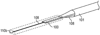
도 1a 는 하나의 실시형태에 따른 세장형의 가요성 부분 및 벤딩 가능한 부분을 포함하는 가이드와이어의 일부의 등각도이다.
도 1b 는 하나의 실시형태에 따른 도 1a 가이드와이어의 일부의 등각도이고 폴리머 슬리브의 섹션은 그 안에 구성 요소들의 상세들을 보여주도록 제거된다.
도 2a 내지 도 2f 는 도 1a 의 세장형의 가요성 부분의 다양한 실시형태들을 예시한다:
도 2a 는 코어의 외부 표면을 따라 원주 방향으로 서로 이격되고 선형으로 배치된 2개의 도전성 와이어들을 예시하는 하나의 실시형태에 따른 세장형의 가요성 부분의 횡단면도이다.
도 2b 는 코어 와이어를 추가로 포함하는 코어의 외부 표면을 따라 원주 방향으로 서로 이격되고 선형으로 배치된 하나의 도전성 와이어를 예시하는 또 다른 실시형태의 횡단면도이다.
도 2c 는 코어 주위에 나선형으로 또는 인터위빙식으로 랩핑되는 도전성 와이어들을 예시하는 또 다른 실시형태에 따른 세장형의 가요성 부분의 코어의 측면도이다.
도 2d 는 세장형의 가요성 부분을 따라 코어와 형성되는 내부 내강을 예시하는 또 다른 실시형태에 따른 세장형의 가요성 부분 및 벤딩 가능한 부분의 측면도이다.
도 2e 는 내부 내강을 통해 통과하는 도전성 와이어들을 예시하는 도 2d 의 세장형의 가요성 부분의 횡단면도이다.
도 2f 는 코어의 외부 표면을 따라 원주 방향으로 서로 이격되고 선형으로 형성된 복수의 그루브들을 예시하는 또 다른 실시형태에 따른 세장형의 가요성 부분의 횡단면도이다.
도 3a 내지 도 3c 는 테이퍼링된 단부가 세장형의 가요성 부분의 원위 단부에 제공되는 다양한 실시형태들에 따른 도 1a 의 가이드와이어의 세장형의 가요성 부분 및 벤딩 가능한 부분를 예시한다:
도 3a 는 하나의 실시형태에 따른 세장형의 가요성 부분 및 벤딩 가능한 부분의 일부의 등각도이고 폴리머 슬리브의 섹션은 그 안에 구성 요소들의 상세들을 보다 양호하게 보여주도록 실선들로 나타낸다.
도 3b 는 그것이 벤딩 가능한 부분에 제공된 이온 전기활성 폴리머 액추에이터의 근위 단부와 커플링되도록 세장형의 가요성 부분에 접근할 때에 단면적에서 감소되는 기하학적 형상을 갖는 테이퍼링된 단부를 예시하는 하나의 실시형태에 따른 도 3a 의 세장형의 가요성 부분 및 벤딩 가능한 부분의 측면도이다.
도 3c 는 폴리머 전해질 부재의 근위 단부 내에 끼워지는 테이퍼링된 단부를 예시하는 또 다른 실시형태에 따른 도 3a 의 세장형의 가요성 부분 및 벤딩 가능한 부분의 측단면도이다.
도 4a 는 직선 모드로 벤딩 가능한 부분을 예시하는 도 1a 및 도 1b 의 하나의 실시형태의 벤딩 가능한 부분의 일부의 등각도이다.
도 4b 는 변형된 또는 벤딩 모드로 도 4a 의 벤딩 가능한 부분의 일부의 사시도이다.
도 4c 는 네개의 전기 신호들의 처음에 선택된 세트가 벤딩 이동에서 2개의 자유도를 제공하도록 폴리머 전해질 부재의 외부 표면 주위에 배치된 네개의 원주 방향으로 분포된 전극들에 인가되는 하나의 실시형태를 예시하는 도 4a 및 도 4b 의 벤딩 가능한 부분의 일부의 횡단면도이다.
도 4d 는 네개의 전기 신호들의 두번째로 선택된 세트가 폴리머 전해질 부재 주위에 배치된 원주 방향으로 분포된 전극들에 인가되는 또 다른 실시형태를 나타내는 도 4a 및 도 4b 의 벤딩 가능한 부분의 일부의 횡단면도이다.
도 5 는 벤딩 이동에서 하나의 자유도를 제공하는 로드형 이온 전기활성 폴리머 액추에이터를 예시하는 또 다른 실시형태에 따른 벤딩 가능한 부분의 가이드와이어의 부분의 일부의 등각도이다.
도 6a 는 또 다른 실시형태에 따른 세장형의 가요성 부분 및 벤딩 가능한 부분을 포함하는 가이드와이어의 등각도이다.
도 6b 는 도 6a 의 등각도이고 폴리머 슬리브의 섹션은 그 안에 구성 요소들의 상세들을 보다 양호하게 보여주도록 실선들로 나타낸다.
도 6c 는 샌드위치-구조형 이온 전기활성 폴리머 액추에이터를 예시하는 도 6a 및 도 6b 의 벤딩 가능한 부분의 등각도이다.
도 7a 는 이온 전기활성 폴리머 액추에이터의 근위 단부에 형성된 전도성 브릿지 (13) 를 예시하는, 또 다른 실시형태에 따른 가이드와이어의 벤딩 가능한 부분 및 폴리머 슬리브를 갖지 않는 세장형의 가요성 부분의 측단면도이다.
도 7b 는 폴리머 슬리브를 갖는 도 7a 의 세장형의 가요성 부분의 측단면도를 예시한다.
도 8a 는 하나의 실시형태에 따른 도 2d 와 일반적으로 동일한 구성을 갖지만 변경되지 않은 가이드와이어의 세장형의 가요성 부분 및 벤딩 가능한 부분의 측면도를 예시한다.
도 8b 는 도 8a 의 벤딩 가능한 부분의 측면도이다.
도 9a 내지 도 9c 는 세장형의 가요성 부분의 코어의 원위 단부에 제공된 테이퍼링된 단부 및 이온 전기활성 폴리머 액추에이터의 일체화를 개략적으로 예시한다:
도 9a 는 하나의 실시형태에 따른 도 6a 및 도 6b 에 도시된 가이드와이어의 코어 및 이온 전기활성 폴리머 액추에이터를 도시한다.
도 9b 는 도 6a 및 도 6b 하나의 실시형태에 따른 가이드와이어의 코어 및 이온 전기활성 폴리머 액추에이터의 등각도이다.
도 9c 는 도 9b 의 등각도이고 이온 전기활성 폴리머 액추에이터의 섹션은 그 안에 구성 요소들의 상세들을 보다 양호하게 보여주도록 실선들로 나타낸다.
도 10a 내지 도 10d 는 세장형의 가요성 부분의 코어 및 이온 전기활성 폴리머 액추에이터의 전극들과 도전성 와이어들의 일체화를 개략적으로 예시한다:
도 10a 는 하나의 실시형태에 따른 도 6a 및 도 6b 에 도시된 가이드와이어의 코어, 이온 전기활성 폴리머 액추에이터 및 도전성 와이어들의 등각도이다.
도 10b 는 도 10a 의 측면도이다.
도 10c 는 도 10a 의 등각도이고 이온 전기활성 폴리머 액추에이터의 섹션은 그 안에 구성 요소들의 상세들을 보다 양호하게 보여주도록 실선으로 나타낸다.
도 10d 는 도 10a 의 측면도이고 이온 전기활성 폴리머 액추에이터의 섹션은 그 안에 구성 요소들의 상세들을 보다 양호하게 보여주도록 실선들로 나타낸다.
도 11a 내지 도 11e 는 코어, 이온 전기활성 폴리머 액추에이터의 근위 단부 및 도전성 와이어들에 걸쳐 둘러싸는 폴리머 슬리브의 일체화를 개략적으로 예시한다:
도 11a 는 하나의 실시형태에 따른 가이드와이어의 세장형의 가요성 부분 및 벤딩 가능한 부분의 등각도이고, 세장형의 가요성 부분은 코어 및 코어 (1) 를 둘러싸는 폴리머 슬리브를 포함하는 한편 벤딩 가능한 부분은 도 6a 및 도 6b 에 도시된 이온 전기활성 폴리머 액추에이터 (110b) 를 포함한다.
도 11b 는 도 11a 의 측면도이다.
도 11c 는 도 11a 의 등각도이고 폴리머 슬리브의 섹션은 그 안에 구성 요소들의 상세들을 보다 양호하게 보여주도록 실선들로 나타낸다.
도 11d 는 도 11a 의 측면도이고 폴리머 슬리브의 섹션은 그 안에 구성 요소들의 상세들을 보다 양호하게 보여주도록 실선들로 나타낸다.
도 11e 는 도 11a 의 측면도이고 폴리머 슬리브의 섹션 및 이온 전기활성 폴리머 액추에이터는 그 안에 구성 요소들의 상세들을 보다 양호하게 보여주도록 실선들로 나타낸다.1A is an isometric view of a portion of a guidewire that includes an elongate flexible portion and a bendable portion according to one embodiment.
FIG. 1B is an isometric view of a portion of the guidewire of FIG. 1A according to one embodiment and a section of the polymer sleeve is removed to show details of the components therein.
2A-2F illustrate various embodiments of the elongate flexible portion of FIG. 1A:
2A is a cross-sectional view of an elongate flexible portion in accordance with one embodiment illustrating two conductive wires spaced apart and linearly spaced from one another in the circumferential direction along the outer surface of the core.
FIG. 2B is a cross-sectional view of another embodiment illustrating one conductive wire spaced apart and linearly spaced from each other in the circumferential direction along the outer surface of the core further including the core wire.
2C is a side view of the core of an elongate flexible portion according to another embodiment illustrating conductive wires spirally or interweaving wrapped around the core.
2D is a side view of an elongate flexible portion and a bendable portion according to another embodiment illustrating an inner lumen formed with a core along an elongated flexible portion.
FIG. 2E is a cross-sectional view of the elongate flexible portion of FIG. 2D illustrating conductive wires passing through the inner lumen. FIG.
2F is a cross-sectional view of an elongate flexible portion according to another embodiment illustrating a plurality of grooves formed linearly spaced apart from each other in the circumferential direction along the outer surface of the core.
3A-3C illustrate the elongate flexible portion and the bendable portion of the guidewire of FIG. 1A according to various embodiments in which a tapered end is provided at the distal end of the elongate flexible portion:
3A is an isometric view of an elongate flexible portion and a portion of a bendable portion according to one embodiment and the section of the polymer sleeve is shown in solid lines to better show details of the components therein.
FIG. 3B is in one embodiment illustrating a tapered end having a geometry that is reduced in cross-sectional area when approaching the elongate flexible portion such that it is coupled with the proximal end of the ion electroactive polymer actuator provided in the bendable portion. 3A is a side view of the elongate flexible and bendable portion of FIG. 3A.
3C is a side cross-sectional view of the elongate flexible portion and bendable portion of FIG. 3A according to another embodiment illustrating a tapered end fitted within the proximal end of the polymer electrolyte member.
4A is an isometric view of a portion of the bendable portion of one embodiment of FIGS. 1A and 1B illustrating the bendable portion in a straight mode.
4B is a perspective view of a portion of the bendable portion of FIG. 4A in a modified or bending mode.
4C illustrates one embodiment where an initially selected set of four electrical signals is applied to four circumferentially distributed electrodes disposed around the outer surface of the polymer electrolyte member to provide two degrees of freedom in bending movement. Is a cross sectional view of a portion of the bendable portion of FIGS. 4A and 4B.
4D is a cross-sectional view of a portion of the bendable portion of FIGS. 4A and 4B showing another embodiment where a second selected set of four electrical signals is applied to circumferentially distributed electrodes disposed around the polymer electrolyte member. .
5 is an isometric view of a portion of a portion of a guidewire of a bendable portion according to another embodiment illustrating a rod-type ion electroactive polymer actuator that provides one degree of freedom in bending movement.
6A is an isometric view of a guidewire that includes an elongate flexible portion and a bendable portion according to another embodiment.
FIG. 6B is an isometric view of FIG. 6A and the section of the polymer sleeve is shown in solid lines to better show the details of the components therein.
6C is an isometric view of the bendable portion of FIGS. 6A and 6B illustrating a sandwich-structured ion electroactive polymer actuator.
7A is a side cross-sectional view of a bent portion of a guidewire according to another embodiment and an elongate flexible portion without a polymer sleeve, illustrating a
FIG. 7B illustrates a side cross-sectional view of the elongate flexible portion of FIG. 7A with a polymer sleeve.
FIG. 8A illustrates a side view of an elongate flexible portion and a bendable portion of a guidewire that are generally the same configuration as FIG. 2D, but unaltered, according to one embodiment.
8B is a side view of the bendable portion of FIG. 8A.
9A-9C schematically illustrate the integration of a tapered end and an ion electroactive polymer actuator provided at the distal end of the core of an elongate flexible portion:
9A illustrates the core and ion electroactive polymer actuator of the guidewire shown in FIGS. 6A and 6B, according to one embodiment.
9B is an isometric view of the core and ion electroactive polymer actuator of the guidewire according to one embodiment of FIGS. 6A and 6B.
9C is an isometric view of FIG. 9B and the section of the ion electroactive polymer actuator is shown in solid lines to better show the details of the components therein.
10A-10D schematically illustrate the integration of the conductive wires with the electrodes of the core of the elongate flexible portion and the ion electroactive polymer actuator:
10A is an isometric view of the core, ion electroactive polymer actuator, and conductive wires of the guidewire shown in FIGS. 6A and 6B, according to one embodiment.
10B is a side view of FIG. 10A.
10C is an isometric view of FIG. 10A and the section of the ion electroactive polymer actuator is shown in solid lines to better show the details of the components therein.
FIG. 10D is a side view of FIG. 10A and the section of the ion electroactive polymer actuator is shown in solid lines to better show details of the components therein.
11A-11E schematically illustrate the integration of a polymer sleeve surrounding over a core, the proximal end of an ion electroactive polymer actuator and conductive wires:
11A is an isometric view of an elongate flexible portion and a bendable portion of a guidewire according to one embodiment, wherein the elongate flexible portion includes a core and a polymer sleeve surrounding the
11B is a side view of FIG. 11A.
FIG. 11C is an isometric view of FIG. 11A and the section of the polymer sleeve is shown in solid lines to better show details of the components therein.
FIG. 11D is a side view of FIG. 11A and the section of the polymer sleeve is shown in solid lines to better show details of the components therein.
FIG. 11E is a side view of FIG. 11A and the section of the polymer sleeve and the ion electroactive polymer actuator are shown in solid lines to better show details of the components therein.
가이드와이어들과 같은 의료 디바이스들은 충분히 가늘어서 내강, 예를 들면 동맥, 정맥, 목구멍, 귓구멍, 비강, 요도 또는 임의의 수의 다른 내강들 또는 신체의 통로들 내로 삽입될 수 있다. 이들 의료 디바이스들은 외과 의사들에게 외과적 절차 또는 의료용 수술을 수행하기 위해 국소적인 접근을 제공하도록 피실험자 또는 환자를 실질적으로 개방 절단할 필요성을 방지함으로써 종래의 수술과 비교하여 실질적으로 회복 기간을 짧게 만드는 비외과적인 수술의 실행을 가능하게 한다.Medical devices such as guidewires may be sufficiently thin to be inserted into the lumen, for example, arteries, veins, throats, ear canals, nasal passages, urethra or any number of other lumens or passages of the body. These medical devices substantially shorten the recovery period compared to conventional surgery by avoiding the need to substantially open cut the subject or patient to provide surgeons with a local approach to performing a surgical procedure or medical operation. Enables the execution of nonsurgical surgery.
본원에 사용된 바와 같은, 용어 "피실험자" 또는 "환자" 는 디바이스에 의한 의료용 치료 처치를 받는 대상을 칭한다. 소정 양상들에서, 환자는 인간 환자이다. 다른 양상들에서, 환자는 반려, 스포츠, 토착 또는 가축 또는 다른 동물이다.As used herein, the term “subject” or “patient” refers to a subject receiving medical therapeutic treatment by a device. In certain aspects, the patient is a human patient. In other aspects, the patient is companion, sports, indigenous or domestic or other animal.
본원에 사용된 바와 같은, 용어 "이온 전기활성 폴리머 액추에이터" 는 양이온들이 그에 부과된 전기장, 및 폴리머 전해질 부재의 표면에 배치된 하나 이상의 전극들에 응답하여 이동하는 얇은 폴리머 전해질 부재를 포함하는 의료 디바이스의 구성 요소를 칭한다. 본원에 설명된 바와 같이, "이온 전기활성 폴리머 액추에이터" 는 의료 디바이스의 벤딩 가능한 부분에서 원위 단부에 제공되어 그 원위 단부를 이동시키거나 또는 선택적으로 벤딩시키는 것을 담당할 수 있다. 보다 구체적으로, 하나 이상의 전극들의 선택적인 전기 여자는 폴리머 전해질 부재 또는 부재들이 폴리머 전해질 부재의 측 또는 일부를 따른 수축 및/또는 폴리머 전해질 부재의 측 또는 일부를 따른 팽창의 결과로서 비대칭적으로 변형하게 한다. 폴리머 전해질 부재 내에 양이온들은 폴리머 전해질 부재의 매트릭스 내에 유지되면서 에노드에 여자된 전극을 향해, 그리고 캐소드에 여자된 전극으로부터 멀리 이동한다는 것이 이해될 것이다. 이는 에노드에 여자된 전극의 인접에서 폴리머 전해질 부재의 일부가 팽창하게 하고 캐소드에 여자된 전극의 인접에서 폴리머 전해질 부재의 일부가 수축하게 함으로써 폴리머 전해질 부재를 벤딩시킨다. 도전성 와이어들을 통해 전극들로 전달되는 전기 신호들의 균형 잡힌 제어는 의도된 또는 선택된 방향으로 폴리머 전해질 부재의 벤딩을 생성한다. 이완된 또는 비-여자된 상태에서, 이온 전기활성 폴리머 액추에이터의 폴리머 전해질 부재는 그 원래의 형태로 유지된다. As used herein, the term “ion electroactive polymer actuator” refers to a medical device comprising a thin polymer electrolyte member that moves in response to an electric field imposed on it and one or more electrodes disposed on the surface of the polymer electrolyte member. Refers to the components of As described herein, an “ion electroactive polymer actuator” may be provided at the distal end in the bendable portion of the medical device to be responsible for moving or selectively bending the distal end. More specifically, the selective electrical excitation of the one or more electrodes causes the polymer electrolyte member or members to deform asymmetrically as a result of shrinkage along the side or part of the polymer electrolyte member and / or expansion along the side or part of the polymer electrolyte member. do. It will be appreciated that the cations in the polymer electrolyte member move in toward the electrode excited at the anode and away from the electrode excited at the cathode while remaining in the matrix of the polymer electrolyte member. This causes the polymer electrolyte member to bend by causing a portion of the polymer electrolyte member to expand in the vicinity of the electrode excited to the anode and causing the portion of the polymer electrolyte member to contract in the vicinity of the electrode excited to the cathode. Balanced control of electrical signals delivered to the electrodes through the conductive wires creates bending of the polymer electrolyte member in the intended or selected direction. In the relaxed or non-excited state, the polymer electrolyte member of the ion electroactive polymer actuator remains in its original form.
본원에 사용된 바와 같은, 용어 "폴리머 전해질 부재" 는 폴리머 호스트 및 전해질 용매 (예를 들면, 물, 이온 액체 등) 를 포함하는 임의의 형상 또는 형태의 층, 멤브레인, 로드 또는 구성 요소를 칭한다. 폴리머 호스트는 예를 들면, 플루오로폴리머들 및 본질적으로 전도성인 폴리머들을 포함하지만 이에 제한되지 않는다. 예를 들면, 폴리머 전해질 부재는 다공성의 폴리비닐리덴 플루오라이드 또는 폴리비닐리덴 디플루오라이드, 비닐리덴 디플루오라이드의 폴리머화에 의해 생성되고 이온 액체 또는 식염 수용액 (salt water) 을 포함하는 높은 비-반응성 열가소성 플루오로폴리머를 포함할 수 있다. 대안적으로, 폴리머 전해질은 폴리비닐리덴 플루오라이드 또는 폴리비닐리덴 디플루오라이드, 프로필렌카보네이트 및 이온 액체에 의해 형성된 겔을 포함할 수 있다.As used herein, the term “polymer electrolyte member” refers to any shape or form of layers, membranes, rods or components, including polymeric hosts and electrolyte solvents (eg, water, ionic liquids, and the like). Polymeric hosts include, but are not limited to, for example, fluoropolymers and inherently conductive polymers. For example, the polymer electrolyte member is produced by polymerizing porous polyvinylidene fluoride or polyvinylidene difluoride, vinylidene difluoride and contains a high non-aqueous solution containing ionic liquid or salt water. Reactive thermoplastic fluoropolymers. Alternatively, the polymer electrolyte may comprise a gel formed by polyvinylidene fluoride or polyvinylidene difluoride, propylene carbonate and ionic liquid.
본원에 사용된 바와 같은, 용어들 "도전성 와이어" 또는 "도전성 도관" 은 폴리머 전해질 부재의 벤딩에 영향을 주도록 전기 소스로부터 복수의 전극들 중 하나 이상에 전기 신호들을 전도하는 구성 요소를 칭하고, 우수한 화학적 안정성 및 부식 저항성을 위해 귀금속을 포함할 수 있다. 예를 들면, 폴리머 전해질 부재를 액추에이팅시키도록 선택된 전극들로 포텐셜을 전달하는 도전성 와이어들 또는 도관들은 매우 높은 전도성의 백금, 백금 합금, 은 또는 은 합금을 포함하거나 또는 화학적으로 안정적이고 부식 저항을 가질 뿐만 아니라, 전성이고 유리하게 벤딩에 대해 매우 낮은 고유한 저항성을 갖는 매우 가느다란 도전성 와이어들로 형성될 수 있는 금 또는 금 합금을 포함할 수 있지만 이에 제한되지 않는다.As used herein, the terms “conductive wire” or “conductive conduit” refer to a component that conducts electrical signals from an electrical source to one or more of the plurality of electrodes so as to affect bending of the polymer electrolyte member, and Precious metals may be included for chemical stability and corrosion resistance. For example, conductive wires or conduits that deliver the potential to the electrodes selected to actuate the polymer electrolyte member include very high conductivity platinum, platinum alloys, silver or silver alloys or are chemically stable and corrosion resistant In addition to, but not limited to, gold or gold alloys may be formed of very thin conductive wires that are malleable and advantageously have very low inherent resistance to bending.
다음의 단락들은 수술하는 데 유용한 의료 디바이스들, 또는 동일한 것을 사용하여 외과적 수술들의 수행을 가능하게 하는 소정 실시형태들 및, 동일한 것을 위해 그러한 의료 디바이스들의 제조를 가능하게 하는 데 사용될 수 있는 방법을 설명한다. 의료 디바이스들 및 방법들의 다른 실시형태들은 아래에 본원에 첨부된 청구 범위의 범위 내에 있고, 그러한 실시형태들의 예시는 본 발명을 제한하지 않는다는 것이 이해될 것이다. 도 1a 는 가이드와이어 (1) 의 일부의 등각도를 포함하는 의료 디바이스의 하나의 실시형태를 예시한다. 도 1b 는 도 1a 의 가이드와이어 (1) 의 일부의 사시도이고, 폴리머 슬리브는 그 안에 구성 요소들의 상세를 보여주도록 제거된다. 가이드와이어 (1) 는 세장형의 가요성 부분 (10) 및 세장형의 가요성 부분 (10) 의 원위 단부에 배치된 제어 가능하게 벤딩 가능한 부분 (11) 을 포함한다. 세장형 및 가요성 부분 (10) 은 코어 (101) (예를 들면, 도 1b 를 참조) 및 코어 (101) 를 둘러싸는 슬리브 (102) 를 추가로 포함한다. 벤딩 가능한 부분 (11) 은 세장형의 가요성 부분 (100) 의 코어 (101) 에 인접하고 일반적으로 그와 동일 선상이고, 도 1a 및 도 1b 에 위치될 때에 복수의 여자 가능한 전극들 (112) 내에 중앙에 배치된 폴리머 전해질 부재 (111) 를 포함하는 이온 전기활성 폴리머 액추에이터 (110) 를 포함한다. 폴리머 전해질 부재 (111) 의 외부 표면 (113) 을 실질적으로 둘러싸는 복수의 전극들 (112) 의 각각은 복수의 도전성 와이어들 (12) 의 상이한 하나의 원위 단부 (120) 에 연결되고, 복수의 도전성 와이어들을 통해 전기 신호 또는 포텐셜이 그렇게 연결된 전극 (112) 에 공급될 수 있다. The following paragraphs describe medical devices useful for surgery, or certain embodiments that allow for performing surgical operations using the same, and methods that can be used to enable the manufacture of such medical devices for the same. Explain. It is to be understood that other embodiments of the medical devices and methods are within the scope of the claims appended hereto, and examples of such embodiments do not limit the invention. 1A illustrates one embodiment of a medical device that includes an isometric view of a portion of the
도 1 에 도시된 바와 같이, 세장형 및 가요성 부분 (10) 은 세장형 및 가요성 부분 (10) 의 근위 단부 (103) 에 제공되고 오퍼레이터에 의한 조작을 위해 사용 가능한 의료 디바이스의 작동 가능한 부분 (도시 생략) 으로부터 연장 가능하다. 세장형의 가요성 부분 (10) 의 코어 (101) 는 충분히 가늘어서 신체의 내강 (도시 생략) 에 삽입될 수 있다 (도시 생략). 또한, 코어 (101) 는 충분히 가요성을 갖고 실질적으로 축방향으로 압축할 수 없어서 그것이 신체의 내강 (도시 생략) 내로 도입된 후 세장형의 가요성 부분 (10) 를 앞으로 푸시하거나 또는 구동함으로써 휘어진 또는 꾸불꾸불한 좁은 경로를 갖는 내강을 통해 전진될 수 있다. 코어 (101) 는 금속들, 금속 합금들, 폴리머들 등, 또는 그 조합들 또는 혼합물들을 포함하는 임의의 적절한 재료를 포함한다. 적절한 금속들 및 금속 합금들의 몇몇 예들은 스테인레스 강, 예를 들면 304 v 스테인레스 강; 니켈-티타늄 합금, 예를 들면 니티놀, 니켈-크롬 합금, 니켈-크롬-철 합금, 코발트 합금, 등; 또는 다른 적절한 재료를 포함한다. 본원에서 용어 "니티놀" 은 니켈 및 티타늄의 금속 합금을 칭한다. 전체 코어 (101) 는 동일한 재료 (예를 들면 니티놀) 로 제조될 수 있거나, 또는 몇몇 실시형태들에서 상이한 재료들로 제조된 부분들 또는 섹션들을 포함할 수 있다. 몇몇 실시형태들에서, 코어 (101) 를 구성하는 데 사용되는 재료는 샤프트 (101) 의 상이한 부분들에 변화하는 가요성 및 강성도 특성들을 부여하도록 선택된다. 예를 들면, 코어 (101) 의 근위 부분 및 원위 부분은 상이한 재료들 (즉, 상이한 탄성 계수를 갖는 재료들) 로 형성될 수 있어서 그 상이한 위치들에서 코어 (101) 의 가요성에서 차이를 발생시킨다. 몇몇 실시형태들에서, 근위 부분을 구성하는 데 사용되는 재료는 코어 (101) 의 이러한 부분의 푸시성 및 토크성 (현저한 에너지 저장 또는 이력 현상 (hysteresis) 없이 비틀리는 능력) 에 대해 상대적으로 강성일 수 있고, 원위 부분을 구성하는 데 사용되는 재료는 코어 (101) 의 원위 부분의 보다 양호한 측방향 트랙성 및 조향성을 위해 그에 비해 비교적 가요성을 갖는다. 예를 들면, 코어 (101) 의 근위 부분은 직선형의 304v 스테인레스 강 와이어로 형성될 수 있고 코어 (101) 의 원위 부분은 직선형의 초탄성 또는 선형의 탄성 합금 (예를 들면, 니티놀) 와이어로 형성될 수 있다. 도 2a 내지 도 2f 는 세장형의 가요성 부분 (10) 의 다양한 실시형태들을 예시한다. 몇몇 실시형태들에서, 코어 (101) 는 중실 횡단면을 갖는다 (도 2a, 2b, 2c 및 2f 를 참조). 도 2b 의 중실 코어 실시형태에서, 코어 (101) 는 중실 금속성 재료 (104) 를 포함하는 금속성 코어 와이어이다. 중실 금속성 재료 (104) 를 갖는 코어 (101) 는 전극들 (112) 의 적어도 하나에 커플링되고 부가적인 도전성 도관으로서 역할을 하여 전기 신호들을 전기 소스로부터 복수의 전극들 (112) 의 하나 이상으로 선택적으로 전도하여 폴리머 전해질 부재 (111) 의 벤딩을 제어할 수 있고, 따라서 코어 (101) 의 외부 표면 (105) 에 부착된 도전성 와이어들 (12) 의 수는 따라서 감소되고, 예를 들면 도 2a 의 2개의 도전성 와이어들 (12) 과 비교되는 바와 같이 하나의 도전성 와이어 (12) 로 감소될 수 있다. 몇몇 대안적인 실시형태들에서, 코어 (101) 는 중공의 횡단면을 가질 수 있다. 예를 들면, 도 2d 및 도 2e 에 도시된 바와 같이, 내부 내강 (106) 은 도전성 와이어들 (12) 를 수용하기 위해 세장형 및 가요성 부분 (10) 을 따라 코어 (101) 내에 형성된다. As shown in FIG. 1, the elongate and
폴리머 슬리브 (102) 는 신체 내강 또는 통로 내에서 가이드와이어 조작성을 용이하게 하도록 이온 전기활성 폴리머 액추에이터 (110) 의 일부 및 코어 (101) 를 둘러싼다. 폴리머 슬리브 (102) 는 예를 들면, 열가소성 또는 열경화성 폴리머와 같은 폴리머를 포함한다. 예를 들면, 폴리머 슬리브 (102) 는 폴리에테르 블록 아미드(PEBA), 폴리우레탄, 폴리에테르-에스테르, 폴리에스테르, 폴리아릴에테르케톤 (PAEK) 또는 선형의 낮은-밀도 폴리에틸렌 등, 또는 그 코폴리머들 또는 혼합물들 또는 조합들을 포함할 수 있다. 부가적으로, 폴리머 슬리브 (102) 는 폴리아미드, 엘라스토머 폴리아미드들, 블록 폴리아미드/에테르들, 실리콘들, 폴리에틸렌 등, 또는 그 혼합물들, 조합들, 또는 코폴리머들과 같은 폴리머들을 포함할 수 있거나, 또는 상기 열거된 임의의 다른 재료들을 가질 수 있다. 바람직한 실시형태에서, 폴리머 슬리브 (102) 는 슬리브 (102) 를 위해 비교적 가요성 폴리머 특성들을 제공하도록 PEBAX® (Arkema 로부터 입수 가능) 또는 폴리테트라플루오로에틸렌 (PTFE) 또는 그 조합을 포함한다. 폴리머 슬리브 (102) 을 위한 몇몇 다른 적절한 예시적인 재료들은 나일론, 폴리에테르에테르케톤 (PEEK), 폴리이미드 (PI), 폴리에테르이미드 (PEI), 플루오르화된 에틸렌 프로필렌(FEP) 및/또는 퍼플루오로알콕시 폴리머 수지 (PFA) 를 포함한다. 재료들 및 프로세싱 기술들의 신중한 선택을 채용함으로써, 이들 및 다른 재료들의 열가소성, 용매 가용성, 및 열경화성 변형예들이 가요성, 킹크 저항성 등과 같은 원하는 결과들을 달성하도록 채용될 수 있다.The
부가적으로, 몇몇 실시형태들에서, 코팅, 예를 들면 미끄러운 (예를 들면, 친수성) 또는 다른 타입의 코팅이 폴리머 슬리브 (102) 의 일부들 또는 모두, 및/또는 가이드와이어 (1) 의 다른 부분들에 걸쳐 인가될 수 있다. 플루오로폴리머들와 같은 소수성 코팅들은 가이드와이어 핸들링 및 디바이스 교환성들을 개선하는 건식 윤활성을 제공한다. 미끄러운 코팅들은 신체 내강 또는 통로 내에 조향성을 개선시키고, 그 안에서 상해 방지 (lesion crossing) 능력을 개선시킨다. 적절한 미끄러운 폴리머들은 본 기술 분야에서 널리 공지되어 있고 폴리아릴렌 산화물들, 폴리비닐피롤리돈들, 폴리비닐알코올들, 하이드록시 알킬 셀룰로우스들, 알진들, 단당류들, 카프로락톤들 (caprolactones) 등, 및 그 혼합물들 및 조합들과 같은 친수성 폴리머들을 포함할 수 있다. 바람직한 실시형태에서, 폴리머 슬리브 (102) 는 상기 논의된 바와 같은 친수성 폴리머로 코팅된다.Additionally, in some embodiments, a coating, eg, a slippery (eg, hydrophilic) or other type of coating, may be part or all of the
도전성 와이어들 (12) 은 임의의 적절한 연결 기술 (예를 들면 기계적 패스너들 (볼트들 또는 클램프들), 레이저 용접, 초음파 본딩, 브레이징 및 솔더링) 을 사용하여 코어 (101) 에 연결된다. 예를 들면, 도 2a 및 도 2b 에서, 도전성 와이어들 (12) 의 각각은 코어 (101) 의 외부 표면 (105) 의 길이를 따라 선형으로 배치된다. 대안적으로, 복수의 도전성 와이어들 (12) 의 각각은 도 2c 에 도시된 바와 같이 코어 (101) 의 외부 표면 (105) 주위에 나선형으로 또는 인터위빙식으로 랩핑된다. 이때, 도 2a 내지 도 2c 의 도전성 와이어들 (12) 의 각각은 폴리머 슬리브 (102), 코어 (101) 및 이온 전기활성 폴리머 액추에이터 (110) 의 근위 단부의 적어도 일부에 대해 고정된다 (예를 들면 도 1a 를 참조). 다른 실시형태들에서, 도전성 와이어들 (12) 은 도 2d 의 내부 내강 (106) 을 통해 통과할 수 있다. 추가의 또 다른 실시형태에서, 도 2f 에 도시된 바와 같이 복수의 그루브들 (107) 은 코어 (101) 의 외부 표면 (105) 을 따라 선형으로 연장되도록 형성되고, 각각의 그루브는 각각 그안에 도전성 와이어들 (12) 중 하나를 수용한다. 폴리머 슬리브 (102) 는 그 안에 도전성 와이어들 (12) 를 둘러싸도록 그루브들 (107) 을 추가로 덮는다. The
도 3a 및 도 3b 는 하나의 실시형태에 따른 도 1a 의 가이드와이어 (1) 의 세장형의 가요성 부분 (10) 및 벤딩 가능한 부분 (11) 을 예시하고 여기서 테이퍼링된 단부 (108) 는 세장형의 가요성 부분 (10) 의 코어 (101) 의 원위 단부 (100) 의 인접에 제공된다. 코어 (101) 의 직경은 전이부로부터 그 원위 단부로 연장되는 작은 직경 부분, 전이부로부터 그 근위 단부 (도시 생략) 로 연장되는 큰 직경 부분, 및 하나 이상의 테이퍼들 또는 단차들을 따라 큰 직경 부분 내지 작은 직경 부분들 사이에서의 코어 (101) 직경의 전이부를 포함한다. 몇몇 실시형태들에서, 도 3a 내지 도 3b 에 도시된 바와 같이, 폴리머 슬리브 (102) 에 의해 둘러싸인 코어 (101) 는 코어의 표면이 세장형의 원위 단부 (100) 에 가까워질수록 단면적에서 감소하는 기하학적 형상을 갖는 테이퍼링된 부분 (108) 을 갖고, 원위 단부 (100) 에서 코어 (101) 의 작은 직경 부분의 감소된 횡단면은 이온 전기활성 폴리머 액추에이터 (110) 의 근위 단부 (114) 의 표면과 접촉한다. 폴리머 슬리브 (102) 는 이때 코어 (101) 및 이온 전기활성 폴리머 액추에이터 (110) 의 근위 단부 (114) 상에서 상기 설명된 바와 같이 임의의 적절한 폴리머(들) 을 압출함으로써 형성되어 함께 그것들을 단단히 고정한다. 또한, 단단히 상호 연결하도록, 도 3c 에 도시된 다른 실시형태들에서, 코어의 테이퍼링된 단부 (108) 로부터 원위 단부 (100) 로 연장되는 작은 직경 부분은 폴리머 전해질 부재 (111) 의 근위 단부 (114) 의 내향으로 연장되는 그를 위해 제공되는 개구에 끼워진다. 몇몇 실시형태들에서, 테이퍼링된다면, 코어 (101) 는 원하는 전이 특성들에 따라 테이퍼링된 부분 (108) 의 균일한 또는 비-균일한 전이부를 포함할 수 있다. 예를 들면, 코어 (101) 의 테이퍼링된 부분 (108) 의 직경 전이 표면 프로파일은 선형, 곡선형, 또는 단차형일 수 있고, 직경에서 하나보다 많은 전이 타입 또는 변경을 포함할 수 있다. 코어의 센터라인에 대해 임의의 그러한 전이부의 각도는 코어 (101) 의 원하는 가요성 특성들에 따라 변할 수 있다. 테이퍼링된 부분 (108) 의 길이는 코어 (101) 에서 그 길이를 따라 강성도에서 더 많은 (보다 긴 길이) 또는 보다 작은 (보다 짧은 길이) 점진적인 전이부를 얻도록 선택될 수 있다. 코어 (101) 의 테이퍼링된 부분 (108) 은 예를 들면 원통 연삭 (예를 들면 외측 직경 연삭 또는 센터리스 연삭) 에 의해 본 기술 분야에서 공지된 다수의 상이한 기술들 중 임의의 하나에 의해 테이퍼링되거나 또는 성형될 수 있지만, 테이퍼링 방법은 이에 제한되지 않는다. 3A and 3B illustrate the elongate
도 4a 는 직선 모드로 벤딩 가능한 부분 (11) 을 예시하는 도 1a 및 도 1b 의 가이드와이어 (1) 의 실시형태의 벤딩 가능한 부분 (11) 의 단부 부분의 등각도이다. 벤딩 가능한 부분 (11) 은 도 3a 내지 도 3c 의 세장형의 가요성 부분 (10) 의 원위 단부 (100) 의 인접에 배치되고 그 원주, 즉 외부 표면 (113) 에서 각지게-분포된 복수의 여자 가능한 전극들 (112) 에 중앙에 배치된 로드형 폴리머 전해질 부재 (111) 를 포함하는 이온 전기활성 폴리머 액추에이터 (110) 를 포함한다. 폴리머 전해질 부재 (111) 의 외부 표면 (113) 을 둘러싸도록 설계된 복수의 전극들 (112) 의 각각은 전기 신호 또는 포텐셜이 선택적으로 연결된 전극 (112) 에 공급되는 도전성 와이어 (12) 의 원위 단부 (120) 에 연결되고 폴리머 전해질 부재 (111) 의 외부 표면 (113) 의 일부를 형성하는 갭에 의해 서로 이격된다. 하나의 실시형태에서, 이온 전기활성 폴리머 액추에이터 (110) 는 폴리머 전해질 부재 (111) 의 외부 표면 (113) 주위에 등각으로 분포된 복수의 각지게 분포된 전극들 (112) 을 포함할 수 있다. 예를 들면, 도 4a 의 실시형태에서 이온 전기활성 폴리머 액추에이터 (110) 는 폴리머 전해질 부재 (111) 및 네개의 각지게-분포된 전극들 (112) 을 포함하고 상기 네개의 각지게-분포된 전극들은 그들 센터들 또는 센터라인들 (116) 사이에서 약 90 도 (1.571 라디안) 만큼 둘을 구별하여 폴리머 전해질 부재 (111) 의 외부 표면 (113) 을 따라 분리되거나 또는 이격되지만 이에 제한되지 않는다. 또 다른 예로서, 이온 전기활성 폴리머 액추에이터 (110) 는 약 45 도 (0.785 라디안) 만큼 그들 센터라인들 사이에서 폴리머 전해질 부재 (111) 의 외부 표면 (113) 을 따라 분리되는 8개의 각지게-분포된 전극들 (112) 을 포함할 수 있지만, 이에 제한되지 않는다. 추가의 또 다른 예에서, 이온 전기활성 폴리머 액추에이터 (110) 는 약 120 도 (2.094 라디안) 만큼 둘을 구별하여 그들의 센터라인들 사이에서 폴리머 전해질 부재 (111) 의 외부 표면 (113) 을 따라 분리되는 세개의 각지게-분포된 전극들 (112) 을 포함할 수 있다. 복수의 전극들 (112) 의 각각은 폴리머 전해질 부재의 표면을 따라 원주 스팬을 점유하고, "각도 분리" 는 따라서 전극들의 인접한 에지들의 관점에서 대신에 전극들의 센터라인들의 관점에서 언급될 수 있고, 이는 인접한 전극의 인접한 에지에 보다 더 가깝다는 것이 이해될 것이다. 의료 디바이스의 몇몇 실시형태들에서, 전극들은 인접한 전극들을 개재한 절연 채널들로서 실질적인 갭을 제공하는 방식으로 이격된다.4A is an isometric view of the end portion of the
하나의 실시형태에서, 도 4a 의 이온 전기활성 폴리머 액추에이터 (110) 는 이온 폴리머-금속 합성물 (IPMC) 액추에이터이다. 하나의 실시형태에서, 이온 전기활성 폴리머 액추에이터 (110) 는 EMITF (전해질으로서) 로 침지된 PVDF-HFP 로 제조된 폴리머 전해질 부재 (111) 를 포함한다. 대안적으로, 가이드와이어 (1) 의 이온 전기활성 폴리머 액추에이터 (110) 의 다른 실시형태들은 과불화된 이오노머, 예를 들면 Aciplex™ (Asahi Kasei Chemical Corp. of Tokyo, Japan 로부터 입수 가능), Flemion® (AGC Chemical Americas, Inc. of Exton, Pennsylvania, USA 로부터 압수 가능), fumapem® F-series (fumatech BWT GmbH, Bietigheim-Bissingen, Federal Republic of Germany 로부터 입수 가능) 또는 Nafion® ( The Chemours Company of Wilmington, Delaware, USA. 로부터 입수 가능) 을 포함하는 폴리머 전해질 부재 (111) 를 포함할 수 있다.In one embodiment, the ion
하나의 실시형태에서, 전극들 (112) 은 백금, 금, 탄소-계 재료, 또는 그 조합 (예를 들면 합성물) 중 하나를 포함할 수 있다. 탄소-재료는 예를 들면 카바이드-유래된 탄소 (CDC), 탄소 나노튜브 (CNT), 그래핀, 카바이드-유래된 탄소 및 폴리머 전해질 부재 (111) 의 합성물, 및 탄소 나노튜브 및 폴리머 전해질 부재 (111) 의 합성물을 포함할 수 있지만 이에 제한되지 않는다. 예시적인 실시형태에서, 전극들 (112) 은 탄소 (CDC 및/또는 CNT) 및 PVDF-HFP/EMITF 의 합성물을 포함하는 충 및 금 층을 포함하는 이중 층이다. 전극들 (112) 은 임의의 적절한 기술들을 사용하여 폴리머 전해질 부재 (111) 의 외부 표면 (113) 에서 일체형으로 된다. 예를 들면, 금속 전극들 (112) (예를 들면 백금 또는 금 전극들) 은 전기화학적 프로세스를 사용하여 그에 디포짓팅될 수 있지만 이에 제한되지 않는다. 대안적으로, 이중 층 전극들 (112) 은 다음의 단계들에 의해 외부 표면 (113) 에서 제조되고 일체형으로 될 수 있다: 외부 표면 (113) 에 탄소-계 재료 층을 스프레이하는 단계, 탄소-계 재료 층에 금 층을 스프레이 코팅한 후, 이어서 리플로우 프로세스를 사용하여 탄소-계 재료 층 및 금 층을 일체형으로 하는 단계. 리플로우 프로세스의 상세는 PCT 출원 No. PCT/US17/16513 에 논의되어 있고, 그 전체가 참조로써 본원에 완전히 통합된다. 벤딩 가능한 부분 (11) 은 복수의 전극들 (112) 중 하나 이상의 선택적인 여자에 의해 벤딩된 모드로 선택적으로 그리고 제어 가능하게 변형될 수 있고, 이는 다음에 추가로 상세하게 설명될 것이다. 도 4b 는 변형된 또는 벤딩 모드로 도 4a 의 벤딩 가능한 부분 (11) 의 일부의 등각도이다. 복수의 전극들 (112) 의 각각은 와이어 (12) 가 연결된 전극 (112) 에 전기 신호가 인가됨으로써, 폴리머 전해질 부재 (111) 내에 금속 양이온들을 전극들 (112) 의 개별적인 하나들에 선택적으로 인가된 캐소드 또는 애노드 전위의 존재에 의해 결정된 방향으로 이동시키는 도전성 와이어 (12) (도 1b) 의 원위 단부 (120) 에 연결된다. 인가된 전위에 의해 발생된 이러한 양이온 이동은 폴리머 전해질 부재 (111) 를, 애노드 포텐셜이 공급되는 전극에 근위에 배치된 폴리머 전해질 부재 (111) 의 일부에서 팽창시키고 결과적으로 폴리머 전해질 부재 (111) 의 남아있는 비팽창된 부분의 방향으로 벤딩 또는 랩핑시킨다. 그 결과로서, 이온 전기활성 폴리머 액추에이터 (110) 의 폴리머 전해질 부재 (111) 의 벤딩 변형의 규모 및 방향은 전극들 (112) 중 어떤 것을 여자시킬 지를 전략적으로 선택함으로써 그리고 도전성 와이어 (12) 를 통해 전극들 (112) 로 인가되는 전위의 부호 (+ 또는 -) 또는 규모를 조정함으로써 제어될 수 있다.In one embodiment, the
대안적으로, 벤딩 가능한 부분 (11) 이 복수의 전극들 (112) 중 하나 이상으로 하나 이상의 전위들을 인가하지 않을 때에도 변형된 (벤딩된) 모드로 관찰되는 경우에, 관찰된 편향의 규모는 벤딩의 결과로서 와이어들 중 상이한 하나들에 부과된 상이한 전위들을 감지함으로써 결정될 수 있고, 전압 소스로부터 전기적으로 포텐셜을 부과함으로써 자유 상태로부터 벤딩된 상태로 벤딩 가능한 부분 (11) 의 벤딩 정도로 그들 포텐셜(들) 동등화시켜서, 벤딩 가능한 부분 (11) 에 인가된 외부력의 규모 및 방향을 결정하거나 또는, 대안적으로, 전극들 (112) 에 공지된 포텐셜의 인가가 벤딩 가능한 부분 (11) 의 예상된 변형을 발생시키는 것에 실패하는 경우에, 예상된 변형과 실제 변형 (존재한다면) 사이의 차이는 가이드와이어 (1) 의 벤딩 가능한 부분 (11) 에 인가된 외부력의 규모의 지표로서 사용될 수 있다.Alternatively, when the
도 4c 는 네개의 전위들 중에 처음에 선택된 세트가 2개의 벤딩 자유도 (예를 들면 X-축선 방향 및/또는 Y-축선 방향을 따른 벤딩) 를 제공하도록 폴리머 전해질 부재 (111) 의 외부 표면 (113) 주위에 배치된 네개의 원주 방향으로 분포된 전극들 (112) 에 인가되는 하나의 실시형태를 예시하는 도 4a 및 도 4b 의 벤딩 가능한 부분 (11) 의 횡단면도이다. 도 4c 는 화살표 2 의 방향으로 벤딩 가능한 부분 (11) 의 벤딩을 부여하도록 복수의 각지게 분포된 전극들 (112) 에 인가된 전위의 차지 (부호) 를 예시한다. 도 4c 의 벤딩 가능한 부분 (11) 의 좌측 및 우측에서 전극들 (112) 에 양의 포텐셜의 인가는, 도 4c 의 상단에서 전극 (112) 에 양의 포텐셜의 인가 뿐만 아니라, 그리고 추가로 도 4c 의 바닥에서 전극 (112) 에 음의 포텐셜의 인가 뿐만 아니라, 단지 남아있는 전극들 (112) 에 부여되는 음의 포텐셜 및 도 4c 의 상단에서 전극 (112) 에 양의 포텐셜의 인가의 결과로서 발생하는 것과 상이한 양의 변형을 발생시킨다는 것이 이해될 것이다. 사용자는 사용자가 원하는 변형을 발생시키도록 복수의 전기 신호들을 선택할 수 있다는 것이 이해될 것이다.4C shows the outer surface of the
도 4d 는 네개의 전위들 중 두번째 선택된 세트가 폴리머 전해질 부재 (111) 주위에 배치된 원주 방향으로 분포된 전극들 (112) 에 인가되는 또 다른 실시형태를 나타내는 도 4a 및 도 4b 의 벤딩 가능한 부분 (11) 의 횡단면도이다. 도 4d 는 도 4d 의 벤딩 가능한 부분 (11) 의 상단에서의 전극 (112) 및 또한 도 4d 의 벤딩 가능한 부분 (11) 의 우측에서 전극 (112) 에 양의 포텐셜의 인가를 예시하고, 도 4d 는 도 4d 의 바닥에서 전극 (112) 및 또한 도 4d 의 좌측에서 전극 (112) 에 음의 포텐셜의 인가를 추가로 예시한다. 이들 전위들의 인가로부터 기인하는 폴리머 전해질 부재 (111) 의 변형은 화살표 3 의 방향이다.4D illustrates the bendable portion of FIGS. 4A and 4B, showing another embodiment in which a second selected set of four potentials is applied to the circumferentially distributed
가이드와이어 (1) 의 벤딩 가능한 부분 (11) 은 복수의 방향들로 벤딩될 수 있고 전기 차지들의 전략적 제어에 의해 변형 또는 편향의 변화 정도는 개별적인 전극들 (112) 의 각각에 부여된다는 것을 도 4c 및 도 4d 로부터 이해될 것이다. 도 4a 내지 도 4d 에 예시된 실시형태는 네개의 전극들 (112) 을 포함하는 벤딩 가능한 부분 (11) 을 예시하지만, 가이드와이어 (1) 의 액추에이팅 작동 부품 (100) 의 벤딩 가능한 부분 (11) 은 네개보다 작은 또는 네개보다 많은 전극들 (112) 을 포함할 수 있고, 그러한 다른 실시형태들은 편향 및 변형 방향 용량을 상이하게 하고 따라서 보다 많은 또는 보다 적은 자유도를 제공할 것이라는 것이 이해될 것이다. The
도 5 는 2개의 원주 방향으로 분포된 전극들이 벤딩 모션 (예를 들면 위로 또는 아래로) 에서 하나의 자유도를 제공하도록 로드형 폴리머 전해질 부재 (111a) 의 외부 표면 (113a) 주위에 각각 배치되는 이온 전기활성 폴리머 액추에이터 (110a) 의 또 다른 실시형태에 따른 가이드와이어 (1) 의 벤딩 가능한 부분 (11) 의 등각도이다. 상단 전극 (112a) 은 로드형 폴리머 전해질 부재 (111a) 의 외부 표면 (113) 의 상단에 배치되고 바닥 전극 (112a') 은 외부 표면 (113a) 의 바닥 주위에 대칭적으로 배치된다. 상기 설명된 바와 같이, 예를 들면, 여자된 상단 전극 (112a) 에 인접한 폴리머 전해질 부재 (111a) 의 상단 부분이 수축되는 한편 (도 5 의 상단 전극 (112a) 에 양의 포텐셜의 인가가 주어질 때에), 여자된 바닥 전극 (112a') 의 인접한 폴리머 전해질 부재 (111a) 의 바닥 부분은 팽창함으로써 (바닥 전극 (112a') 에 음의 포텐셜의 인가가 주어질 때), 폴리머 전해질 부재 (111a) 는 화살표 4 의 방향으로 벤딩한다. 5 shows ions disposed around the
도 6a 는 가이드와이어 (1) 의 일부의 등각도를 포함하는 의료 디바이스의 또 다른 실시형태를 예시한다. 도 6b 는 도 6a 의 가이드와이어의 등각도이고 위에 놓인 폴리머 슬리브는 그 안에 구성 요소들의 상세를 나타내도록 도 6b 에서 가상선으로 도시된다. 상세들은 세장형의 가요성 부분 (10) 에 관한 것이고 그 구성 요소들은 상기 단락들을 참조하여 이해될 수 있다. 상기 설명된 실시형태들과 비교하여, 도 6a 및 도 6b 의 가이드와이어 (1) 의 이온 전기활성 폴리머 액추에이터 (110b) 는 상이한 횡단면 형상으로 본원에 제공된다. 예를 들면, 하나의 실시형태에서, 도 6c 는 횡단면에서 직사각형을 예시하는 도 6a 및 도 6b 의 가이드와이어 (1) 의 벤딩 가능한 부분 (11), 또는 보다 구체적으로 2개의 원주 방향으로 분포된 전극들 - "샌드위치" 구조를 형성하도록 폴리머 전해질 부재 (111b) 의 단면에서 직사각형의 상단 및 바닥 외부 표면 (113b) 주위에 각각 배치된 상단 전극 (112b) 및 바닥 전극 (112b') - 을 갖는 "샌드위치-구조형" 이온 전기활성 폴리머 액추에이터 (110b) 의 등각도이지만 이에 제한되지 않는다. "샌드위치-구조형" 이온 전기활성 폴리머 액추에이터 (110b) 는 임의의 적절한 기술들에 의해 제조될 수 있다. 예를 들면, 하지만 이에 제한되지 않는, 전극들 (112b, 112b') 은 그 캐스팅에 의해 제조될 수 있고 이때 부가적인 정확한 마이크로 기계가공 없이 열 프레싱을 사용하여 직사각형 폴리머 전해질 부재 (111b) 와 조립됨으로써, 그러한 프로세싱으로부터 기인할 수 있는, 인접한 전극들과 수반되는 개방 회로 사이에 존재하는 절연 채널들을 형성하는 갭이 발생하지 않는다. 유사하게, 이온 전기활성 폴리머 액추에이터 (110b) 는 상단 전극 (112b) 및 바닥 전극 (112b') 이 반대 부호 또는 포텐셜, 즉, + 및 - 의 전위로 여자될 때에 벤딩 모션 (예를 들면 Y-축선 방향으로 위로 또는 아래로) 에서 하나의 자유도를 제공하는 도 5 에 설명된 바와 같이 벤딩될 수 있다.6A illustrates another embodiment of a medical device that includes an isometric view of a portion of the
도전성 와이어들 (12) 은 임의의 적절한 연결 기술들을 사용하여 전극들 (112) 과 상호 연결된다. 예를 들면, 도 3b 및 도 3c 의 실시형태에서, 도전성 와이어들 (12) 은 전도성 페이스트 또는 레이저 용접을 사용하여 이온 전기활성 폴리머 액추에이터 (110) 의 근위 단부 (114) 에서 전극들 (112) 의 각각의 적어도 일부와 상호 연결된다 (예를 들면 일체형으로 되고 끼워진다). 이때, 폴리머 슬리브 (102) 는 코어 (101), 근위 단부 (114) 의 일부 및 그에 연결된 도전성 와이어들 (12) 의 위에 놓여서, 그것들을 함께 단단히 고정시킨다.
도 7a 는 또 다른 실시형태에 따른 가이드와이어의 세장형의 가요성 부분 (10) 및 벤딩 가능한 부분 (11) 의 측단면도를 예시한다. 여기서, 전도성 브릿지 (13) 는 전극들 (112) 및 폴리머 전해질 부재 (111) 과 인터페이싱하고 그 사이에서 전기 신호들의 전송을 용이하게 하도록 이온 전기활성 폴리머 액추에이터 (110) 의 근위 단부 (114) 의 표면에 걸쳐 형성된다. 도전성 와이어 (12) 는 세장형의 가요성 부분 (10) 의 근위 단부 (103) (예를 들면 도 1a 를 참조) 로부터 원위 단부 (100) 및 테이퍼링된 단부 (108) 의 일부까지 코어 (101) 의 외부 표면 (105) 에서 상호 연결된다. 테이퍼링된 부분으로부터 그 원위 단부 (100), 및 따라서 도전성 와이어 (12) 의 원위 단부 (120) 까지 연장되는 코어 (101) 의 감소된 직경 부분은 폴리머 전해질 부재 (111) 에 제공된 개구 내에 끼워지고 감소된 직경이 연장되는 개구의 내향으로 전도성 브릿지 (113) 가 연장되는 경우에, 전도성 브릿지 (13) 와 와이어 (12) 사이에 보다 큰 접촉 면적이 달성된다. 감소된 직경 부분의 원위 단부 (100) 의 팁은 도 7a 및 도 7b 에 도시된 바와 같이 폴리머 전해질 부재에 개구의 터미널 단부로부터 이격될 수 있거나, 또는 그에 대해 그라운딩될 수 있다. 전도성 브릿지 (13) 는 임의의 적절한 기술들을 사용하여 (예를 들면 접착제들, 코팅, 플레이팅, 에칭 또는 디포짓팅을 사용하여, 그러나 이에 제한되지 않음) 전극들 (112) 및 폴리머 전해질 부재 (111) 의 표면에 전도성 폴리머들을 포함하는 금속성 재료들 (예를 들면 금, 은 또는 구리) 또는 비-금속성 재료들로 제조된 임의의 전도성 포일 또는 테이프를 적용함으로써 제조될 수 있다. 이때, 도 7b 에 도시된 바와 같이, 코어 (101) 및 이온 전기활성 폴리머 액추에이터 (110) 의 근위 단부 (114) 의 일부 및 그에 연결된 도전성 와이어들 (12) 위에 놓여진 폴리머 슬리브 (102) (가상선으로 도시됨) 는 함께 그들을 단단히 고정한다. 7A illustrates a cross-sectional side view of an elongate
도 8a 는 하나의 실시형태에 따른 도 2d 에 대해 본원에서 설명되고 도시된 것과 일반적으로 동일한 구성을 갖는 가이드와이어 (1) 의 세장형의 가요성 부분 (10) 및 벤딩 가능한 부분 (11) 의 측단면도를 예시한다. 도 8b 는 도 8a 의 벤딩 가능한 부분 (11) 의 측단면도를 예시한다. 내부 내강 (106) 은 세장형 및 가요성 부분 (10) 의 길이에 걸쳐 코어 (101) 내에서 형성되고 상응하는 내강은 그 근위 단부 (114) 에서 폴리머 전해질 부재 (111) 의 일부 내로 연장된다. 도 8b 에서, 개별적인 전도성 브릿지들 (13a) 는 전극들 (112) 및 폴리머 전해질 부재 (111) 를 함께 전기 연결시키도록 이온 전기활성 폴리머 액추에이터 (110) 의 원위 단부 (115) 에 제공되게 도시되고, 도전성 와이어들 (12) 은 내부 내강 (106) 을 통해 통과되고 그 근위 단부 (114) 로부터 원위 단부 (115) 까지 폴리머 전해질 부재 (111) 내에 끼워짐으로써, 솔더링, 크림핑, 스테플링, 핀칭, 용접, 전도성 접착제 (예를 들면, 전도성 에폭시를 사용함) 등과 같은 종래의 와이어 본딩 기술들을 사용하여 전도성 브릿지들 (13a) 을 전기 연결한다.8A is a side of an elongate
도 6a 및 도 6b 를 다시 참조하면, "샌드위치-구조형" 이온 전기활성 폴리머 액추에이터 (110b) 는 다음의 예시적인 방법에 의해 제조될 수 있다. 폴리머 전해질 부재 (111b) 는 처음에 아세톤, 디메틸아세트아미드 (DMAc) 등과 같은 적절한 용매로 플루오로폴리머 수지 (예를 들면 폴리(비닐리덴 플루오라이드-코-헥사플루오로프로필렌(P(VDF-HFP)) 를 용해시킴으로써 제조된다. 얻어진 PVDF-HFP 제형은 이때 닥터 블레이드 (Doctor blade) 방법을 사용하여 폴리테트라플루오로에틸렌 (PTFE) 기재에서 캐스팅되고 실온에서 경화된다. 부가적으로, PVDF-HFP 필름은 용매 잔여물들을 제거하도록 80 ℃ 에서 진공 하에서 건조된다. 마지막으로, PVDF-HFP 필름은 2개의 PTFE 플레이트들 사이에서 열 프레싱되고 2 시간동안 200-240 ℃ 에서 어닐링된다. 실온으로 냉각한 후에, PVDF-HFP 필름은 PTFE 기재로부터 벗겨진다. 최종 필름 두께는 약 50-60 ㎛ 이다. 다음에, 폴리머 필름은 적어도 12 시간동안 60-90 ℃ 에서 1-에틸-3-메틸이미다졸륨 비스(트리플루오로메틸술포닐)이미드 (EMIMTFSI) 또는 1-에틸-3-메틸이미다졸륨 트리플루오로메탄술포네이트 (EMITF) 와 같은 적절한 이온 액체 전해질로 침지된다.Referring again to FIGS. 6A and 6B, the “sandwich-structured” ion
이때, 상단 전극 (112b) 및 바닥 전극 (112b') 은 다음의 예시적인 실시형태에 따라 얻어진 폴리머 전해질 부재 (111b) 의 상단 및 바닥 외부 표면 (113b) 주위에 각각 배치된다. 층형의 상단 전극 (112b) 및 바닥 전극 (112b') 을 위해 사용된 탄소-폴리머 합성물은 용매 (예를 들면 디메틸아세트아미드 (DMAc)) 에서 원하는 전도성 탄소 재료, PVDF-HFP 및 이온 액체를 포함하는 분산제에 의해 제조된다. 본원에서 사용된 전도성 탄소 재료는 카바이드-유래된 탄소 (CDC), 탄소 나노튜브들, 탄소 에어로겔, 그래핀 또는 다른 탄소 동소체 또는 그 조합일 수 있다. 탄소-폴리머 혼합물은 동질의 분산제를 달성하도록 4 시간 동안 상승된 온도로 교반된다. 이때, 분산제는 4 시간동안 초음파 욕 및 초음파 프로브에 의해 처리된다. 이후로, 얻어진 탄소 분산제는 Doctor's blade 방법을 사용하여 PTFE 기재에서 캐스팅되고 적어도 14 시간동안 실온에서 건조된다. 그후에, 필름은 5 시간동안 80 ℃ 에서 진공 하에서 건조된다. 마지막으로, 탄소-폴리머 합성물 필름은 10-30 분동안 200-240 ℃ 에서 열 프레싱된다.At this time, the
얻어진 탄소-폴리머 합성물 필름의 도전성은 사용된 탄소 재료의 타입으로 인해 이온 전기활성 폴리머 액추에이터 (110b) 에 대해 적절한 전기기계적 성능을 제공하는 데 종종 불충분하다. 따라서, 몇몇 실시형태들에서, 100-150 nm 의 두께를 갖는 얇은 금 포일이 전도성 집전 장치로서 역할을 하고 전극의 도전성을 증가시키도록 얻어진 탄소-폴리머 합성물 필름에 걸쳐 코팅될 수 있다. 대안적으로, 다른 실시형태들에서, 탄소-폴리머 합성물 필름은 상단 전극 (112b) 및 바닥 전극 (112b') 을 형성하도록 스프레이-코팅 프로세스를 사용하여 금 나노입자 분산제 코팅으로 덮혀질 수 있다.The conductivity of the resulting carbon-polymer composite film is often insufficient to provide adequate electromechanical performance for the ion
마지막으로, 얻어진 폴리머 전해질 부재 (111b), 상단 전극 (112b) 및 바닥 전극 (112b') 은 "샌드위치-구조형", 라미네이트된 이온 전기활성 폴리머 액추에이터 (110b) 를 형성하도록 사용된 전극 구성 및 탄소 재료의 타입에 따라 2-8 분동안 200-240 ℃ 에서 열 프로세싱을 사용하여 조립된다. 몇몇 실시형태들에서, 이온 전기활성 폴리머 액추에이터 (110b) 의 총 두께는 약 90-110 ㎛ 이다. 가이드와이어 (1) 의 벤딩 가능한 부분 (11) 에서 사용되도록, 하나의 실시형태에서, 얻어진 이온 전기활성 폴리머 액추에이터 (110b) 는 12 mm 의 길이를 갖는 300 ㎛ 폭의 스트립으로 커팅될 수 있다.Finally, the resulting
도 6a 및 도 6b 에 도시된 가이드와이어를 제조하기 위한 프로세스는 도 9 내지 도 11 에 도시된 바와 같이 예시된다. 도 9a 내지 도 9c 는 세장형의 가요성 부분 (10) 의 코어 (101) 의 원위 단부 (100) 에서 테이퍼링된 부분 (108) 의 원위에서 코어 (100) 의 감소된 폭 부분 및 이온 전기활성 폴리머 액추에이터 (110b) 의 일체화를 개략적으로 예시한다. 도 9a 는 도 6a 및 도 6b 에 도시된 가이드와이어의 이온 전기활성 폴리머 액추에이터 (110) 및 코어 (101) 를 도시하는 분해도이다. 도 9b 는 코어 (101) 및 코어 (101) 에 조립된 도 6a 및 도 6b 에서 도시된 가이드와이어의 이온 전기활성 폴리머 액추에이터 (110) 의 등각도이다. 도 9c 는 도 9b 의 사시도이고 이온 전기활성 폴리머 액추에이터 (110) 의 섹션은 그안에 구성 요소들을 보다 양호하게 보이게 하도록 가상선으로 도시된다. 도 9a 에 도시된 바와 같이, 상단 전극 (112b) 및 바닥 전극 (112b') 은 직사각형 폴리머 전해질 부재 (111b) 의 상단 및 바닥 외부 표면들 (113b) 주위에 각각 배치되고, 코어의 직사각형의 단면에서 감소된 폭 부분은 코어 (101) 의 테이퍼링된 부분 (108) 의 원위로 연장된다. 도 9b 및 도 9c 에서, 코어의 감소된 폭 부분 및 테이퍼링된 부분 (108) 의 일부는 이때 라미네이트된 "샌드위치" 구조를 형성하도록 임의의 적절한 기술 (예를 들면 열 프레싱, 리플로우잉 등) 을 사용하여 2개의 직사각형 폴리머 전해질 부재 (111b) 사이에서 샌드위치된다. The process for manufacturing the guidewire shown in FIGS. 6A and 6B is illustrated as shown in FIGS. 9-11. 9A-9C show the reduced width portion of the
도 10a 내지 도 10d 는 세장형의 가요성 부분 (10) 의 코어 (101) 및 이온 전기활성 폴리머 액추에이터 (110b) 의 전극들 (112b, 112b') 의 도전성 와이어들 (12) 에 연결을 개략적으로 예시한다. 도 10a 는 하나의 실시형태에 따른 가이드와이어의 코어, 이온 전기활성 폴리머 액추에이터 및 도전성 와이어들의 사시도이다. 도 10b 는 도 10a 의 측면도이다. 도 10c 는 도 10a 의 사시도이고 이온 전기활성 폴리머 액추에이터는 그 안에 구성 요소들의 상세들을 보다 양호하게 나타내도록 가상선으로 도시된다. 도 10d 는 도 10a 의 측면도이고 이온 전기활성 폴리머 액추에이터는 그 안에 구성 요소들의 상세들을 보다 양호하게 나타내도록 가상선으로 도시된다. 여기서, 도 10a 내지 도 10d 에 도시된 도전성 와이어들 (12) 은 그 근위 단부 (103) 로부터 원위 단부 (100) 로 코어 (101) 를 거쳐 권취되고, 이때 도전성 와이어들 (12) 의 각각의 원위 단부 (120) 는 임의의 적절한 연결 기술 (예를 들면 전도성 페이스트 또는 레이저 용접) 을 사용하여 전극들 (112b, 112b') 의 단일한 하나의 표면에 상호 연결된다. 몇몇 실시형태들에서, 테이퍼링된 부분 (108) 의 원위에서 코어 (101) 의 감소된 직경 부분은 도 10c 및 도 10d 에 도시된 바와 같이 그에 보다 양호하게 고정되도록 이온 전기활성 폴리머 액추에이터 (110b) 의 원위 단부 (115) 에 추가로 끼워진다.10A-10D schematically illustrate the connection to the
도 11a 내지 도 11e 는 코어 (101), 이온 전기활성 폴리머 액추에이터 (110b) 의 근위 단부 (114b) 및 도전성 와이어들 (12) 에 걸쳐 폴리머 슬리브 (102) 의 일체화를 개략적으로 예시한다. 도 11a 는 하나의 실시형태에 따른 가이드와이어의 세장형의 가요성 부분 (10) 및 벤딩 가능한 부분 (11) 의 등각도이고, 세장형의 가요성 부분 (10) 은 코어 (101) (예를 들면, 도 11c 및 도 11d 를 참조) 및 코어 (101) 를 둘러싸는 폴리머 슬리브 (102) 를 포함하는 한편, 벤딩 가능한 부분 (11b) 은 상기 설명된 바와 같이 이온 전기활성 폴리머 액추에이터 (110b) 를 포함한다 (예를 들면 도 9a-도 9c 내지 도 10a 내지 도 10d 를 참조). 도 11b 는 도 11a 의 측면도이다. 도 11c 는 도 11a 의 등각도이고 폴리머 슬리브의 섹션은 그 안의 구성 요소들의 상세들을 보다 양호하게 나타내도록 가상선으로 도시된다. 도 11d 는 도 11a 의 측면도이고 폴리머 슬리브의 섹션은 그 안에 구성 요소들의 상세들을 보다 양호하게 나타내도록 실선들로 도시된다. 도 11e 는 도 11a 의 측면도이고 폴리머 슬리브 및 이온 전기활성 폴리머 액추에이터의 섹션은 그 안에 구성 요소들을 보다 양호하게 나타내도록 가상선으로 도시된다. 도 11a 내지 도 11e 에 도시된 바와 같이, 폴리머 슬리브 (102) 는 가이드와이어 조작성을 용이하게 하기 위해 코어 (101), 이온 전기활성 폴리머 액추에이터 (110b) 의 일부 (즉 근위 단부 (114)) 및 그 위에 도전성 와이어들 (12) 을 둘러싸도록 추가로 제공된다. 폴리머 슬리브 (102) 는 코어 (101) 및 이온 전기활성 폴리머 액추에이터 (110b) 의 근위 단부 (114b) 상에 본원에 설명된 바와 같이 임의의 적절한 폴리머들을 압출함으로써 형성되어 그것들을 함께 단단히 고정시킬 수 있다. 이때, 파릴렌 코팅 (도시 생략) 은 최종 습기 및 유전체 격막 보호를 제공하도록 최종적으로 일체형으로 된 가이드와이어 (1) 의 외부 표면에 추가로 인가된다. 파릴렌 코팅은 또한 가이드와이어 (1) 의 전체 길이에 걸쳐 생체 적합성 및 우수한 윤활성을 제공하는 데 도움을 준다.11A-11E schematically illustrate the integration of the
다양한 변경예들 또는 대안예들이 첨부된 청구 범위에서 규정된 바와 같이 본 발명의 기술적 특징들로부터 벗어나지 않고 본 발명의 상기 설명된 예시적인 실시형태들을 행할 수 있다는 것에 주목해야 한다.It should be noted that various changes or alternatives may be made to the above-described exemplary embodiments of the present invention without departing from the technical features of the present invention as defined in the appended claims.
Claims (25)
적어도 하나의 이온 전기활성 폴리머 액추에이터로서, 상기 이온 전기활성 폴리머 액추에이터는,
적어도 표면을 규정하는 적어도 하나의 폴리머 전해질 부재; 및
상기 적어도 하나의 폴리머 전해질 부재의 표면 주위에 배치된 복수의 전극들을 포함하는, 상기 이온 전기활성 폴리머 액추에이터;
근위 단부 및 상기 이온 전기활성 폴리머 액추에이터에 인접하게 고정된 원위 단부를 규정하는 세장형의 가요성 부분으로서, 상기 세장형의 가요성 부분은 코어 및 상기 코어를 둘러싸는 슬리브를 추가로 포함하는, 상기 세장형의 가요성 부분, 및
상기 복수의 전극들 중 적어도 하나에 커플링된 원위 단부 및 근위 단부를 각각 갖는 복수의 도전성 와이어들을 포함하고;
상기 적어도 하나의 폴리머 전해질 부재는 상기 복수의 전극들 중 적어도 하나에 상기 복수의 도전성 와이어들 중 적어도 하나를 통해 공급된 전위의 인가에 응답하여 비대칭적으로 변형되고,
상기 코어는 상기 세장형의 가요성 부분의 상기 원위 단부에 인접한 테이퍼링된 부분을 포함하고,
상기 코어는 상기 폴리머 전해질 부재의 내향으로 연장되는, 의료 디바이스.As a medical device,
At least one ion electroactive polymer actuator, wherein the ion electroactive polymer actuator is
At least one polymer electrolyte member defining at least a surface; And
The ion electroactive polymer actuator comprising a plurality of electrodes disposed around a surface of the at least one polymer electrolyte member;
The elongate flexible portion defining a proximal end and a distal end fixed adjacent the ion electroactive polymer actuator, the elongate flexible portion further comprising a core and a sleeve surrounding the core; An elongate flexible part, and
A plurality of conductive wires each having a distal end and a proximal end coupled to at least one of the plurality of electrodes;
The at least one polymer electrolyte member is deformed asymmetrically in response to the application of a potential supplied through at least one of the plurality of conductive wires to at least one of the plurality of electrodes,
The core includes a tapered portion adjacent the distal end of the elongate flexible portion,
And the core extends inwardly of the polymer electrolyte member.
상기 슬리브는 상기 세장형의 가요성 부분의 상기 원위 단부로부터 연장되고 상기 이온 전기활성 폴리머 액추에이터의 적어도 일부를 둘러싸는, 의료 디바이스.The method of claim 1,
And the sleeve extends from the distal end of the elongate flexible portion and surrounds at least a portion of the ion electroactive polymer actuator.
상기 도전성 와이어들은 상기 슬리브와 상기 코어 사이에 고정되고 상기 이온 전기활성 폴리머 액추에이터의 적어도 일부에 고정되는, 의료 디바이스.The method of claim 2,
The conductive wires are secured between the sleeve and the core and secured to at least a portion of the ion electroactive polymer actuator.
상기 폴리머 전해질 부재는 전해질 및 플루오로폴리머들 및 본질적으로 전도성인 폴리머들로 이루어지는 그룹으로부터 선택된 폴리머를 포함하는, 의료 디바이스.The method of claim 1,
And the polymer electrolyte member comprises a polymer selected from the group consisting of electrolyte and fluoropolymers and inherently conductive polymers.
상기 플루오로폴리머들은 과불화된 이오노머들, 폴리비닐리덴 디플루오라이드 (PVDF) 또는 그 코-폴리머인, 의료 디바이스.The method of claim 4, wherein
The fluoropolymers are perfluorinated ionomers, polyvinylidene difluoride (PVDF) or co-polymers thereof.
상기 본질적으로 전도성인 폴리머들은 폴리아닐린 (PANI), 폴리피롤 (Ppy), 폴리(3,4-에틸렌디옥시티오펜) (PEDOT), 폴리(p-페닐렌 설파이드) (PPS) 또는 그 조합을 포함하는, 의료 디바이스.The method of claim 4, wherein
The intrinsically conductive polymers include polyaniline (PANI), polypyrrole (Ppy), poly (3,4-ethylenedioxythiophene) (PEDOT), poly (p-phenylene sulfide) (PPS) or combinations thereof. Medical devices.
상기 전극들의 각각은 백금, 금 또는 탄소-계 재료, 또는 그들의 2개 이상의 조합을 포함하는, 의료 디바이스.The method of claim 1,
Each of the electrodes comprises a platinum, gold or carbon-based material, or a combination of two or more thereof.
상기 탄소-계 재료는 카바이드-유래된 탄소, 탄소 나노튜브, 그래핀, 카바이드-유래된 탄소 및 폴리머 전해질 부재의 합성물, 및 탄소 나노튜브 및 폴리머 전해질 부재의 합성물 중 적어도 하나를 포함하는, 의료 디바이스.The method of claim 7, wherein
The carbon-based material comprises at least one of carbide-derived carbon, carbon nanotubes, graphene, carbide-derived carbon and a composite of a polymer electrolyte member, and a composite of carbon nanotubes and a polymer electrolyte member. .
상기 전극들은 그 사이에 동등한 각도로 상기 적어도 하나의 폴리머 전해질 부재 주위에 원주 방향으로 분포되는, 의료 디바이스.The method of claim 1,
And the electrodes are distributed circumferentially around the at least one polymer electrolyte member at an equal angle therebetween.
상기 도전성 와이어들의 각각은 상기 코어의 외부 표면을 따라 선형으로 배치되는, 의료 디바이스.The method of claim 1,
Each of the conductive wires is disposed linearly along an outer surface of the core.
상기 세장형의 가요성 부분은 상기 코어의 외부 표면을 따라 원주 방향으로 서로 이격되고 선형으로 연장되는 복수의 그루브들을 추가로 포함하고, 각각의 그루브는 상기 도전성 와이어들 중 하나를 수용하는, 의료 디바이스.The method of claim 1,
The elongate flexible portion further comprises a plurality of grooves spaced apart from each other in a circumferential direction along the outer surface of the core and extending linearly, each groove containing one of the conductive wires .
상기 복수의 도전성 와이어들의 각각은 그위에 덮혀진 절연 코팅을 추가로 포함하는, 의료 디바이스.The method of claim 1,
Wherein each of the plurality of conductive wires further comprises an insulating coating overlying it.
상기 폴리머 전해질 부재의 표면과 상기 전극들 중 적어도 하나 사이로 연장되는 전도성 브릿지를 추가로 포함하는, 의료 디바이스.The method of claim 1,
And a conductive bridge extending between the surface of the polymer electrolyte member and at least one of the electrodes.
상기 코어는 상기 도전성 와이어들이 안에서 연장되는 내부 내강을 추가로 포함하는, 의료 디바이스.The method of claim 1,
The core further comprises an internal lumen from which the conductive wires extend.
상기 도전성 와이어들은 상기 내부 내강을 통해 추가로 통과하는, 의료 디바이스.The method of claim 14,
The conductive wires further pass through the inner lumen.
상기 복수의 도전성 와이어들의 각각은 상기 코어 주위에 나선형으로 또는 인터위빙식으로 랩핑되는, 의료 디바이스.The method of claim 1,
Each of the plurality of conductive wires spirally or interweaving wrapped around the core.
상기 코어는, 부가적인 도전성 도관으로서 역할을 하고 상기 복수의 전극들 중 적어도 하나에 커플링되는 금속성 재료를 포함하는, 의료 디바이스.The method of claim 1,
The core comprises a metallic material that serves as an additional conductive conduit and is coupled to at least one of the plurality of electrodes.
상기 이온 전기활성 폴리머 액추에이터는 2개의 이동 자유도를 제공하도록 구성되는, 의료 디바이스.The method of claim 1,
The ion electroactive polymer actuator is configured to provide two degrees of freedom of movement.
네개의 전극들은 상기 폴리머 전해질 부재의 표면 주위에 동등한 각도 정도로 서로 원주 방향으로 분포되는, 의료 디바이스.The method of claim 18,
And the four electrodes are distributed circumferentially with each other by an equal angle around the surface of the polymer electrolyte member.
상기 이온 전기활성 폴리머 액추에이터는 하나의 이동 자유도를 제공하도록 구성되는, 의료 디바이스.The method of claim 1,
The ion electroactive polymer actuator is configured to provide one degree of freedom of movement.
상기 폴리머 전해질 부재는 로드형 형상이고, 2개의 전극들은 상기 폴리머 전해질 부재의 표면 주위에 동등한 각도들로 원주 방향으로 분포되는, 의료 디바이스.The method of claim 20,
Wherein the polymer electrolyte member is rod-shaped and two electrodes are circumferentially distributed at equal angles around the surface of the polymer electrolyte member.
상기 폴리머 전해질 부재는 직사각형 형상이고 상단 표면 및 상응하는 바닥 표면을 규정하고, 2개의 전극들은 샌드위치 구조를 형성하도록 대칭적으로 상기 폴리머 전해질 부재의 상기 상단 표면 및 상기 바닥 표면 주위에 원주 방향으로 분포되는, 의료 디바이스.The method of claim 20,
The polymer electrolyte member is rectangular in shape and defines a top surface and a corresponding bottom surface, and the two electrodes are circumferentially distributed around the top surface and the bottom surface of the polymer electrolyte member symmetrically to form a sandwich structure. , Medical device.
상기 코어는 상기 폴리머 전해질 부재의 근위 단부의 내향으로 연장되는, 의료 디바이스.The method of claim 22,
And the core extends inwardly of the proximal end of the polymer electrolyte member.
Applications Claiming Priority (5)
| Application Number | Priority Date | Filing Date | Title |
|---|---|---|---|
| US201762539346P | 2017-07-31 | 2017-07-31 | |
| US201762539338P | 2017-07-31 | 2017-07-31 | |
| US62/539,338 | 2017-07-31 | ||
| US62/539,346 | 2017-07-31 | ||
| PCT/US2018/044059 WO2019027826A2 (en) | 2017-07-31 | 2018-07-27 | Steerable medical device and the preparing method thereof |
Publications (2)
| Publication Number | Publication Date |
|---|---|
| KR20190120157A KR20190120157A (en) | 2019-10-23 |
| KR102086979B1 true KR102086979B1 (en) | 2020-03-09 |
Family
ID=65234016
Family Applications (2)
| Application Number | Title | Priority Date | Filing Date |
|---|---|---|---|
| KR1020197010800A Active KR102086979B1 (en) | 2017-07-31 | 2018-07-27 | Steerable Medical Device and Manufacturing Method Thereof |
| KR1020197010799A Active KR102118837B1 (en) | 2017-07-31 | 2018-07-27 | Steerable medical device with braided structure and method for manufacturing same |
Family Applications After (1)
| Application Number | Title | Priority Date | Filing Date |
|---|---|---|---|
| KR1020197010799A Active KR102118837B1 (en) | 2017-07-31 | 2018-07-27 | Steerable medical device with braided structure and method for manufacturing same |
Country Status (11)
| Country | Link |
|---|---|
| US (4) | US10835716B2 (en) |
| EP (5) | EP3548130B1 (en) |
| JP (2) | JP6831455B2 (en) |
| KR (2) | KR102086979B1 (en) |
| CN (2) | CN109843368B (en) |
| AU (2) | AU2018311844B9 (en) |
| BR (1) | BR112019007377B1 (en) |
| CA (2) | CA3039267C (en) |
| MX (2) | MX2019004430A (en) |
| TW (2) | TWI679036B (en) |
| WO (2) | WO2019027826A2 (en) |
Families Citing this family (33)
| Publication number | Priority date | Publication date | Assignee | Title |
|---|---|---|---|---|
| US11877722B2 (en) | 2009-12-15 | 2024-01-23 | Cornell University | Method and apparatus for manipulating the side wall of a body lumen or body cavity |
| US11986150B2 (en) | 2009-12-15 | 2024-05-21 | Lumendi Ltd. | Method and apparatus for manipulating the side wall of a body lumen or body cavity so as to provide increased visualization of the same and/or increased access to the same, and/or for stabilizing instruments relative to the same |
| US9986893B2 (en) | 2009-12-15 | 2018-06-05 | Cornell University | Method and apparatus for manipulating the side wall of a body lumen or body cavity so as to provide increased visualization of the same and/or increased access to the same, and/or for stabilizing instruments relative to the same |
| US12121209B2 (en) | 2014-02-11 | 2024-10-22 | Cornell University | Method and apparatus for providing increased visualization and manipulation of a body side wall |
| WO2019133438A1 (en) | 2017-12-29 | 2019-07-04 | Xcath, Inc. | Steerable surgical robotic system |
| CN110789129A (en) * | 2019-06-28 | 2020-02-14 | 东莞科威医疗器械有限公司 | A kind of reinforced medical cannula and its making method |
| CN110575603A (en) * | 2019-10-14 | 2019-12-17 | 苏州法兰克曼医疗器械有限公司 | A guidewire delivery device with visual function |
| EP4076624A1 (en) * | 2019-12-16 | 2022-10-26 | Galvani Bioelectronics Limited | Stent-electrode intravascular neuromodulator and associated methods for activation of a nerve |
| US20220392065A1 (en) | 2020-01-07 | 2022-12-08 | Cleerly, Inc. | Systems, methods, and devices for medical image analysis, diagnosis, risk stratification, decision making and/or disease tracking |
| US11969280B2 (en) | 2020-01-07 | 2024-04-30 | Cleerly, Inc. | Systems, methods, and devices for medical image analysis, diagnosis, risk stratification, decision making and/or disease tracking |
| KR20220124217A (en) | 2020-01-07 | 2022-09-13 | 클리어리, 인크. | Systems, methods and devices for medical image analysis, diagnosis, risk stratification, decision-making and/or disease tracking |
| CN111729106B (en) * | 2020-06-30 | 2021-08-13 | 北京航空航天大学 | A flexible low temperature plasma sterilization device |
| CN112406252B (en) * | 2020-10-12 | 2023-01-17 | 浙江理工大学 | Preparation method of high-performance electrically driven IPMC flexible actuator based on C-CNC cellulose |
| CN112409627A (en) * | 2020-10-12 | 2021-02-26 | 浙江理工大学 | Preparation method of novel mixed cellulose IPMC material |
| WO2022087539A1 (en) | 2020-10-23 | 2022-04-28 | Vicora, Inc. | Actuated thrombectomy device |
| EP4243910A4 (en) * | 2020-11-16 | 2024-12-25 | Lumendi Ltd. | Methods and apparatus for inverting a hollow sleeve and thereafter reverting an inverted hollow sleeve |
| TWI759076B (en) * | 2021-01-15 | 2022-03-21 | 陳映臻 | Medicine delivery device for healing body cavity wound and medicine delivery duct thereof |
| US12318161B2 (en) | 2021-10-05 | 2025-06-03 | Siemens Healthineers Endovascular Robotics, Inc. | Robotic actuation of elongated medical devices |
| CN118925017A (en) * | 2021-10-09 | 2024-11-12 | 上海卓矿鑫生物科技有限公司 | Anti-glossal nasal catheter |
| DE102021132567B4 (en) * | 2021-12-09 | 2024-08-08 | NET New Electronic Technology GmbH | Endoscope and endoscope system for cardio-float applications |
| US12440180B2 (en) | 2022-03-10 | 2025-10-14 | Cleerly, Inc. | Systems, devices, and methods for non-invasive image-based plaque analysis and risk determination |
| US20250217981A1 (en) | 2022-03-10 | 2025-07-03 | Cleerly, Inc. | Systems, methods, and devices for image-based plaque analysis and risk determination |
| US20250143657A1 (en) | 2022-03-10 | 2025-05-08 | Cleerly, Inc. | Systems, devices, and methods for non-invasive image-based plaque analysis and risk determination |
| US12406365B2 (en) | 2022-03-10 | 2025-09-02 | Cleerly, Inc. | Systems, devices, and methods for non-invasive image-based plaque analysis and risk determination |
| US20240041480A1 (en) | 2022-08-02 | 2024-02-08 | Imperative Care, Inc. | Multi catheter system with integrated fluidics management |
| CN115430020A (en) * | 2022-11-08 | 2022-12-06 | 山东百多安医疗器械股份有限公司 | Catheter with flexible electrode |
| KR20250121323A (en) * | 2022-12-13 | 2025-08-12 | 주식회사 쿠라레 | High surface area braid |
| TWI893582B (en) * | 2023-02-03 | 2025-08-11 | 香港商巧捷力醫療機器人有限公司 | A tubular body of a steerable surgical arm for use in endoscopes during surgical procedures and a method of making the same |
| KR102892160B1 (en) * | 2023-05-17 | 2025-11-27 | 국민대학교산학협력단 | Micro Flow Sensor Comprising Sensor Electrode Formed on Wire, Method for Preparing Same and Device for Measuring Blood Flow Comprising Same |
| US12377206B2 (en) | 2023-05-17 | 2025-08-05 | Imperative Care, Inc. | Fluidics control system for multi catheter stack |
| CN116617545B (en) * | 2023-06-09 | 2024-03-22 | 株洲茂物医疗科技有限公司 | Method for manufacturing guide wire and guide wire |
| CN117018395A (en) * | 2023-08-07 | 2023-11-10 | 南京航空航天大学 | A variable stiffness adjustable bending guide wire based on shape memory alloy |
| WO2025076132A1 (en) * | 2023-10-02 | 2025-04-10 | Vicora, Inc. | Medical devices, systems and methods for delivering energy |
Citations (3)
| Publication number | Priority date | Publication date | Assignee | Title |
|---|---|---|---|---|
| JP2007209554A (en) | 2006-02-09 | 2007-08-23 | Terumo Corp | Catheter |
| US20070250036A1 (en) | 2006-04-25 | 2007-10-25 | Boston Scientific Scimed, Inc. | Variable stiffness catheter assembly |
| US20150032027A1 (en) | 2011-08-22 | 2015-01-29 | LAKE REGION MANUFACTURING d/b/a LAKE REGION MEDICAL | Low profile, multi-conductor guidewire |
Family Cites Families (29)
| Publication number | Priority date | Publication date | Assignee | Title |
|---|---|---|---|---|
| US4808157A (en) * | 1987-07-13 | 1989-02-28 | Neuro Delivery Technology, Inc. | Multi-lumen epidural-spinal needle |
| US5415633A (en) * | 1993-07-28 | 1995-05-16 | Active Control Experts, Inc. | Remotely steered catheterization device |
| JPH0810336A (en) | 1994-06-30 | 1996-01-16 | Agency Of Ind Science & Technol | Medical tube |
| US6616996B1 (en) * | 1994-10-28 | 2003-09-09 | Medsource Trenton, Inc. | Variable stiffness microtubing and method of manufacture |
| US5755704A (en) * | 1996-10-29 | 1998-05-26 | Medtronic, Inc. | Thinwall guide catheter |
| US7494474B2 (en) * | 1997-06-04 | 2009-02-24 | Advanced Cardiovascular Systems, Inc. | Polymer coated guidewire |
| US5891114A (en) * | 1997-09-30 | 1999-04-06 | Target Therapeutics, Inc. | Soft-tip high performance braided catheter |
| US6117296A (en) * | 1998-07-21 | 2000-09-12 | Thomson; Timothy | Electrically controlled contractile polymer composite |
| US6464684B1 (en) | 1998-09-09 | 2002-10-15 | Scimed Life Systems, Inc. | Catheter having regions of differing braid densities and methods of manufacture therefor |
| WO2005018428A2 (en) * | 2000-04-03 | 2005-03-03 | Neoguide Systems, Inc. | Activated polymer articulated instruments and methods of insertion |
| US6679836B2 (en) | 2002-06-21 | 2004-01-20 | Scimed Life Systems, Inc. | Universal programmable guide catheter |
| US8398693B2 (en) * | 2004-01-23 | 2013-03-19 | Boston Scientific Scimed, Inc. | Electrically actuated medical devices |
| JP4732798B2 (en) * | 2005-05-19 | 2011-07-27 | 株式会社日立製作所 | Actuators and actuator modules |
| US7553387B2 (en) * | 2005-10-04 | 2009-06-30 | Ilh, Llc | Catheters with lubricious linings and methods for making and using them |
| WO2007057132A1 (en) * | 2005-11-17 | 2007-05-24 | Micromuscle Ab | Medical devices and methods for their fabrication and use |
| US8414632B2 (en) | 2006-03-06 | 2013-04-09 | Boston Scientific Scimed, Inc. | Adjustable catheter tip |
| US20070249909A1 (en) * | 2006-04-25 | 2007-10-25 | Volk Angela K | Catheter configurations |
| US7909844B2 (en) * | 2006-07-31 | 2011-03-22 | Boston Scientific Scimed, Inc. | Catheters having actuatable lumen assemblies |
| US9370640B2 (en) | 2007-09-12 | 2016-06-21 | Novasentis, Inc. | Steerable medical guide wire device |
| US20100069882A1 (en) * | 2008-09-18 | 2010-03-18 | Boston Scientific Scimed, Inc. | Medical device with preferential bending |
| US9717553B2 (en) * | 2010-12-29 | 2017-08-01 | Biosence Webster (Israel) Ltd. | Braid with integrated signal conductors |
| JP6527329B2 (en) * | 2011-05-03 | 2019-06-05 | シファメド・ホールディングス・エルエルシー | Steerable delivery sheath |
| US9147825B2 (en) * | 2012-03-07 | 2015-09-29 | Board of Regents of the Nevada System of Higher Education on behalf of the University of Nevado, Reno | Methods of fabricating multi-degree of freedom shaped electroactive polymer actuators/sensors for catheters |
| CN103860258A (en) * | 2012-12-12 | 2014-06-18 | 北京中孵友信医药科技股份有限公司 | Self-adaptive annular positioning endovascular catheter |
| US20140180089A1 (en) * | 2012-12-21 | 2014-06-26 | Volcano Corporation | System and method for guidewire control |
| US9364635B2 (en) | 2013-09-20 | 2016-06-14 | Covidien Lp | Computer controlled steerable tip guide catheter |
| WO2015061674A1 (en) * | 2013-10-25 | 2015-04-30 | Intuitive Surgical Operations, Inc. | Flexible instrument with grooved steerable tube |
| FR3019993B1 (en) * | 2014-04-16 | 2019-07-19 | Institut National Des Sciences Appliquees De Lyon | CONTROLLED VARIABLE FLEXIBILITY GUIDE WIRE |
| EP3274041B1 (en) * | 2016-02-05 | 2025-12-24 | The Board of Regents of the University of Texas System | Steerable intra-luminal medical device |
-
2018
- 2018-07-27 KR KR1020197010800A patent/KR102086979B1/en active Active
- 2018-07-27 CN CN201880003922.4A patent/CN109843368B/en active Active
- 2018-07-27 EP EP18841377.7A patent/EP3548130B1/en active Active
- 2018-07-27 JP JP2019520807A patent/JP6831455B2/en active Active
- 2018-07-27 AU AU2018311844D patent/AU2018311844B9/en active Active
- 2018-07-27 TW TW107126073A patent/TWI679036B/en active
- 2018-07-27 WO PCT/US2018/044059 patent/WO2019027826A2/en not_active Ceased
- 2018-07-27 US US16/478,435 patent/US10835716B2/en active Active
- 2018-07-27 MX MX2019004430A patent/MX2019004430A/en unknown
- 2018-07-27 CA CA3039267A patent/CA3039267C/en active Active
- 2018-07-27 KR KR1020197010799A patent/KR102118837B1/en active Active
- 2018-07-27 EP EP24202235.8A patent/EP4461200A3/en active Pending
- 2018-07-27 JP JP2019520901A patent/JP6798020B2/en active Active
- 2018-07-27 AU AU2018311843A patent/AU2018311843B2/en active Active
- 2018-07-27 BR BR112019007377-9A patent/BR112019007377B1/en active IP Right Grant
- 2018-07-27 US US16/478,425 patent/US11229775B2/en active Active
- 2018-07-27 CA CA3039269A patent/CA3039269C/en active Active
- 2018-07-27 TW TW107126074A patent/TWI683678B/en active
- 2018-07-27 CN CN201880003921.XA patent/CN110461400B/en active Active
- 2018-07-27 EP EP24181489.6A patent/EP4424352A3/en active Pending
- 2018-07-27 EP EP18842340.4A patent/EP3548131B1/en active Active
- 2018-07-27 EP EP24202301.8A patent/EP4461201A3/en active Pending
- 2018-07-27 WO PCT/US2018/044057 patent/WO2019027825A1/en not_active Ceased
- 2018-07-27 MX MX2020001267A patent/MX2020001267A/en unknown
-
2021
- 2021-12-16 US US17/553,371 patent/US12171958B2/en active Active
-
2024
- 2024-12-23 US US18/999,592 patent/US20250128028A1/en active Pending
Patent Citations (3)
| Publication number | Priority date | Publication date | Assignee | Title |
|---|---|---|---|---|
| JP2007209554A (en) | 2006-02-09 | 2007-08-23 | Terumo Corp | Catheter |
| US20070250036A1 (en) | 2006-04-25 | 2007-10-25 | Boston Scientific Scimed, Inc. | Variable stiffness catheter assembly |
| US20150032027A1 (en) | 2011-08-22 | 2015-01-29 | LAKE REGION MANUFACTURING d/b/a LAKE REGION MEDICAL | Low profile, multi-conductor guidewire |
Also Published As
Similar Documents
| Publication | Publication Date | Title |
|---|---|---|
| KR102086979B1 (en) | Steerable Medical Device and Manufacturing Method Thereof | |
| JP2020513863A6 (en) | Manipulable medical devices and their manufacturing methods | |
| KR102708262B1 (en) | The manipulatable intraruminal medical device | |
| HK40011281A (en) | Steerable medical device and the preparing method thereof | |
| HK40011281B (en) | Steerable medical device and the preparing method thereof | |
| HK40004551A (en) | Steerable medical device with braided structure and the preparing method thereof | |
| HK40004551B (en) | Steerable medical device with braided structure and the preparing method thereof | |
| BR112019007355B1 (en) | FLEXIBLE MEDICAL DEVICE | |
| BR122022025739B1 (en) | ELONGATED AND FLEXIBLE MEDICAL DEVICE |
Legal Events
| Date | Code | Title | Description |
|---|---|---|---|
| PA0105 | International application |
Patent event date: 20190415 Patent event code: PA01051R01D Comment text: International Patent Application |
|
| A201 | Request for examination | ||
| PA0201 | Request for examination |
Patent event code: PA02012R01D Patent event date: 20191002 Comment text: Request for Examination of Application |
|
| PG1501 | Laying open of application | ||
| PA0302 | Request for accelerated examination |
Patent event date: 20191122 Patent event code: PA03022R01D Comment text: Request for Accelerated Examination |
|
| E902 | Notification of reason for refusal | ||
| PE0902 | Notice of grounds for rejection |
Comment text: Notification of reason for refusal Patent event date: 20191211 Patent event code: PE09021S01D |
|
| E701 | Decision to grant or registration of patent right | ||
| PE0701 | Decision of registration |
Patent event code: PE07011S01D Comment text: Decision to Grant Registration Patent event date: 20200217 |
|
| GRNT | Written decision to grant | ||
| PR0701 | Registration of establishment |
Comment text: Registration of Establishment Patent event date: 20200303 Patent event code: PR07011E01D |
|
| PR1002 | Payment of registration fee |
Payment date: 20200303 End annual number: 3 Start annual number: 1 |
|
| PG1601 | Publication of registration | ||
| PR1001 | Payment of annual fee |
Payment date: 20221221 Start annual number: 4 End annual number: 4 |
|
| PR1001 | Payment of annual fee |
Payment date: 20241223 Start annual number: 6 End annual number: 6 |