KR102086756B1 - Apparatus and method for generating a high dynamic range image - Google Patents
Apparatus and method for generating a high dynamic range image Download PDFInfo
- Publication number
- KR102086756B1 KR102086756B1 KR1020180068212A KR20180068212A KR102086756B1 KR 102086756 B1 KR102086756 B1 KR 102086756B1 KR 1020180068212 A KR1020180068212 A KR 1020180068212A KR 20180068212 A KR20180068212 A KR 20180068212A KR 102086756 B1 KR102086756 B1 KR 102086756B1
- Authority
- KR
- South Korea
- Prior art keywords
- light region
- luminance
- reflected light
- value
- ldr
- Prior art date
- Legal status (The legal status is an assumption and is not a legal conclusion. Google has not performed a legal analysis and makes no representation as to the accuracy of the status listed.)
- Active
Links
Images


Classifications
-
- G—PHYSICS
- G06—COMPUTING OR CALCULATING; COUNTING
- G06T—IMAGE DATA PROCESSING OR GENERATION, IN GENERAL
- G06T5/00—Image enhancement or restoration
- G06T5/90—Dynamic range modification of images or parts thereof
- G06T5/92—Dynamic range modification of images or parts thereof based on global image properties
-
- G06T5/009—
-
- G—PHYSICS
- G06—COMPUTING OR CALCULATING; COUNTING
- G06T—IMAGE DATA PROCESSING OR GENERATION, IN GENERAL
- G06T5/00—Image enhancement or restoration
- G06T5/40—Image enhancement or restoration using histogram techniques
-
- G—PHYSICS
- G06—COMPUTING OR CALCULATING; COUNTING
- G06T—IMAGE DATA PROCESSING OR GENERATION, IN GENERAL
- G06T2207/00—Indexing scheme for image analysis or image enhancement
- G06T2207/20—Special algorithmic details
- G06T2207/20172—Image enhancement details
- G06T2207/20208—High dynamic range [HDR] image processing
Landscapes
- Physics & Mathematics (AREA)
- General Physics & Mathematics (AREA)
- Engineering & Computer Science (AREA)
- Theoretical Computer Science (AREA)
- Studio Devices (AREA)
- Image Processing (AREA)
Abstract
하이 다이내믹 레인지 이미지 생성 장치가, 로우 다이내믹 레인지 이미지에서 반사광 영역을 검출하고, 반사광 영역의 반사도에 따라 로우 다이내믹 레인지 이미지를 반사광 영역과 확산광 영역으로 구분하는 기준 값인 LDR 휘도 경계값을 결정한다. LDR 휘도 경계값과 동일한 값을 초기 출력 휘도 값으로 매핑되도록 초기 매핑 곡선을 생성하고, 확산광 영역의 평균 휘도와 지역 적응 망막 반응 값을 고려하여 LDR 휘도 경계값에 대응하는 매핑 곡선 변형 출력 휘도 값을 결정한다. 그리고 입력 휘도 값과 매핑 곡선 변형 출력 휘도 값을 토대로 초기 출력 매핑 곡선의 기울기를 변형한다.The high dynamic range image generating apparatus detects the reflected light region in the low dynamic range image, and determines the LDR luminance boundary value, which is a reference value for dividing the low dynamic range image into the reflected light region and the diffused light region, according to the reflectance of the reflected light region. Generate an initial mapping curve so that the same value as the LDR luminance threshold is mapped to the initial output luminance value, and the mapping curve modified output luminance value corresponding to the LDR luminance boundary value in consideration of the average luminance of the diffused light region and the local adaptive retinal response value Determine. The slope of the initial output mapping curve is modified based on the input luminance value and the mapping curve modification output luminance value.
Description
본 발명은 하이 다이내믹 레인지 이미지 생성 장치 및 방법에 관한 것이다.The present invention relates to an apparatus and method for generating high dynamic range images.
하이 다이나믹 레인지 이미징(HDR imaging: High Dynamic Range Imaging) 기법은 기존의 휘도 출력 범위보다 더 넓은 휘도 범위를 출력하고 색 재현율을 높여, HDR 디스플레이에 출력할 수 있는 HDR 영상을 제작하는 기술이다. HDR 영상은 기존 단일 노출 영상보다 더 넓은 휘도 범위를 저장하여 기존 단일 노출 영상이 저장하지 못한 휘도 정보까지 저장할 수 있다. 기존 HDR 이미징 기법으로 다중 노출 영상을 이용하여 HDR 영상의 계조를 매핑하는 방법과 단일 노출 영상을 이용하여 HDR 영상의 계조를 매핑하는 방법 등 다양하게 있다. High Dynamic Range Imaging (HDR imaging) is a technology that produces HDR images that can be output to HDR displays by outputting a wider luminance range and increasing color reproducibility than conventional luminance output ranges. The HDR image may store a wider luminance range than the existing single exposure image, and may store luminance information that the existing single exposure image may not store. Existing HDR imaging techniques include a method of mapping the grayscale of an HDR image using a multiple exposure image, and a method of mapping the grayscale of an HDR image using a single exposure image.
기존 HDR 이미징 기법들 중 고정된 기준 값(threshold value)을 기준으로 단일 노출 영상의 밝은 영역과 어두운 영역을 구분하여 각 영역의 밝기를 매핑하는 기술로 HDR 영상을 제작하는 경우, 고정된 기준 값과 모서리(edge)를 검출하는 필터를 이용하여 밝은 영역을 검출하기 때문에 영상의 특성에 따라 검출 성능이 강인하지 못하는 단점이 있다. 그리고 최종적인 인지적 밝기를 고려하지 않고 출력 디스플레이의 휘도 범위만을 고려하기 때문에 결과 영상이 인지적으로 화질이 저하될 수 있다는 단점이 있다. Among conventional HDR imaging techniques, when the HDR image is produced by dividing the bright and dark areas of a single exposure image based on a fixed threshold value and mapping the brightness of each region, the HDR reference and the fixed reference value Since bright areas are detected using a filter for detecting edges, detection performance may not be robust according to characteristics of an image. In addition, since only the luminance range of the output display is considered without considering the final cognitive brightness, the resultant image may be cognitively degraded.
또 다른 기법으로 HDR 영상을 제작하는 경우, 입력 영상에서 반사광 영역을 추출할 때 크기가 다른 2개의 저역 필터(low-pass filter)를 이용하여 기준 값을 도출하기 때문에, 반사광 영역의 크기와 필터의 크기에 따라 성능이 달라진다. 그리고 반사광 영의 기준 값이 달라지더라도 출력 매핑 값이 고정되어 있어, 인지적 밝기가 고려되지 않으므로 HDR 이미징의 성능을 보장하기 어렵다. In another technique, when the HDR image is produced, the reference value is derived by using two low-pass filters having different sizes when extracting the reflected light region from the input image. Performance depends on size. The output mapping value is fixed even if the reference value of the reflected light zero is changed, so that cognitive brightness is not taken into account, so it is difficult to guarantee the performance of HDR imaging.
또 다른 기법인 인간의 시각 모델에 기반하여 지역적 망막 반응을 사용하여 인지적 화질을 중심으로 매핑하는 기술을 이용할 경우, 지역적 망막 반응을 고려한 시그모이드 곡선을 이용하여 출력 매핑을 진행하기 때문에 포화 영역의 계조(gradation) 세분화 성능이 떨어진다. 그리고 지역적 영역의 평균 밝기를 고려하기 위해 사용된 양방향(bilateral) 필터링은 최적의 값을 찾기 위해 여러 번 수행되므로, 실시간 적용이 어렵다. Another technique, which is based on the human visual model, uses the local retinal response to map cognitive image quality, and the saturation region because the output mapping is performed using the sigmoid curve considering the local retinal response. Gradation segmentation performance of is poor. In addition, since bilateral filtering used to consider the average brightness of the local region is performed several times to find an optimal value, real-time application is difficult.
영상의 통계적 정보를 이용하여 감마 확장을 이용하는 방법 경우에는, 입력 영상을 분석한 후 감마(gamma) 곡선을 이용하여 매핑이 결정되기 때문에 포화(saturated) 영역을 효율적으로 계조 세분화하기 어렵다. 그리고, 매핑 구간에서 디스플레이의 출력 휘도를 고려하지 않으므로 인지적 화질 저하가 발생할 수 있다. In the method of using gamma extension using statistical information of an image, it is difficult to effectively grayscale the saturated region because the mapping is determined by using a gamma curve after analyzing the input image. In addition, since the output luminance of the display is not taken into account in the mapping period, cognitive image quality deterioration may occur.
따라서, 본 발명은 인지 밝기 기반의 역 톤 매핑 기법을 사용하는 하이 다이내믹 이미지 생성 장치 및 방법을 제공한다.Accordingly, the present invention provides an apparatus and method for generating high dynamic image using inverse tone mapping based on perceived brightness.
상기 본 발명의 기술적 과제를 달성하기 위한 본 발명의 하나의 특징인 이미지 생성 장치가, 하나의 로우 다이내믹 레인지 이미지로부터 하이 다이내믹 레인지 이미지를 생성하는 방법으로서,According to an aspect of the present invention, there is provided a method for generating a high dynamic range image from one low dynamic range image.
상기 로우 다이내믹 레인지 이미지에서 반사광 영역을 검출하고, 상기 반사광 영역의 반사도에 따라 상기 로우 다이내믹 레인지 이미지를 반사광 영역과 확산광 영역으로 구분하는 LDR 휘도 경계값을 결정하는 단계, 확산광 영역의 평균 휘도와 지역 적응 망막 반응 값을 고려하여 HDR 휘도 경계값 범위를 결정하고, 상기 결정한 HDR 휘도 경계값 범위 내에서 상기 확산광 영역의 평균 휘도와 반사광 영역의 평균 휘도를 이용하여 상기 LDR 휘도 경계값에 대응하는 최종 HDR 휘도 경계값을 결정하는 단계, 상기 입력 휘도 값과 상기 최종 HDR 휘도 경계값을 토대로 초기 LDR-HDR 휘도 변환 그래프에서 확산광 영역의 기울기와 반사광 영역 기울기를 변형하는 단계, 그리고 기울기가 변형된 출력 LDR-HDR 휘도 변환 그래프를 기초로 상기 로우 다이내믹 레인지 이미지의 휘도를 변형하여, 상기 하이 다이내믹 레인지 이미지로 생성하는 단계를 포함한다.Detecting a reflected light region from the low dynamic range image and determining an LDR luminance boundary that divides the low dynamic range image into a reflected light region and a diffused light region according to the reflectivity of the reflected light region, The HDR luminance boundary value range is determined in consideration of a regional adaptive retinal response value, and the HDR luminance boundary value corresponds to the LDR luminance boundary value using the average luminance of the diffused light region and the average luminance of the reflected light region within the determined HDR luminance boundary value range. Determining a final HDR luminance boundary value, modifying a slope of a diffused light region and a slope of a reflected light region in an initial LDR-HDR luminance conversion graph based on the input luminance value and the final HDR luminance boundary value, and changing the slope Output of the low dynamic range image based on an output LDR-HDR luminance conversion graph. Modifying the luminance to produce the high dynamic range image.
상기 본 발명의 기술적 과제를 달성하기 위한 본 발명의 또 다른 특징인 이미지 생성 장치가, 로우 다이내믹 레인지 이미지(Low Dynamic Range, LDR)로부터 하이 다이내믹 레인지(High Dynamic Range, HDR) 이미지를 생성하는 방법으로서,As another aspect of the present invention, there is provided a method for generating a high dynamic range (HDR) image from a low dynamic range image (LDR). ,
상기 로우 다이내믹 레인지 이미지를 반사광 영역과 확산광 영역으로 구분하는 LDR 휘도 경계값을 결정하는 단계, 제1 LDR-HDR 휘도 변환 그래프에서 상기 LDR 휘도 경계값에 대응하는 제1 HDR 휘도 경계값을 제2 HDR 휘도 경계값으로 변경하는 단계, 상기 제1 LDR-HDR 휘도 변환 그래프에서 상기 LDR 휘도 경계값에 대응하는 HDR 휘도를 상기 제2 HDR 휘도 경계값으로 변경하여 상기 확산광 영역의 LDR-HDR 휘도 변환 기울기와 상기 반사광 영역의 LDR-HDR 휘도 변환 기울기가 다른 제2 LDR-HDR 휘도 변환 그래프를 생성하는 단계, 그리고 상기 제2 LDR-HDR 휘도 변환 그래프를 기초로 상기 로우 다이내믹 레인지 이미지의 휘도를 변환하여 상기 하이 다이내믹 레인지 이미지를 생성하는 단계를 포함한다.Determining an LDR luminance boundary value for dividing the low dynamic range image into a reflected light region and a diffused light region, and a second HDR luminance boundary value corresponding to the LDR luminance boundary value in a first LDR to HDR luminance conversion graph Changing to the HDR luminance threshold value, converting the HDR luminance corresponding to the LDR luminance threshold value to the second HDR luminance threshold value in the first LDR-HDR luminance conversion graph to convert the LDR-HDR luminance of the diffused light region; Generating a second LDR-HDR luminance conversion graph having a different slope and an LDR-HDR luminance conversion gradient of the reflected light region, and converting the luminance of the low dynamic range image based on the second LDR-HDR luminance conversion graph Generating the high dynamic range image.
본 발명에 따르면 단일 노출 영상 한 장을 이용하여 HDR 이미지를 생성할 수 있다.According to the present invention, it is possible to generate an HDR image using a single exposure image.
또한, 입력 이미지의 특성에 따라 적응적으로 기준 값을 선정하기 때문에, 이미지의 특성에 강인하게 반사광 영역과 확산광 영역을 검출할 수 있다.In addition, since the reference value is adaptively selected according to the characteristics of the input image, the reflected light region and the diffused light region can be detected robustly to the characteristics of the image.
또한 출력 매핑 시, 적응적인 지역적 망막 반응(adaptive local retina response)를 통해 인지적 화질을 향상시킬 수 있다In addition, cognitive quality can be enhanced by adaptive local retina response in output mapping.
도 1은 본 발명의 실시예에 따른 하이 다이내믹 레인지 이미지 생성 장치의 구조도이다.
도 2는 본 발명의 실시예에 따른 하이 다이내믹 레인지 이미지 생성 방법에 대한 흐름도이다.
도 3a 및 도 3b는 본 발명의 실시예에 따른 후보 반사광 영역 추출 방법에 대한 흐름도 및 예시도이다.
도 4a 및 도 4b는 본 발명의 실시예에 따른 반사광 영역을 결정하는 방법에 대한 흐름도 및 예시도이다.
도 5a 내지 도 5d는 본 발명의 실시예에 따른 초기 LDR-HDR 휘도 변환 그래프 생성 방법에 대한 흐름도 및 예시도이다.
도 6a 및 도 6b는 본 발명의 실시예에 따른 최종 LDR-HDR 휘도 변환 그래프 생성 방법에 대한 흐름도 및 예시도이다.
도 7a 및 도 7b는 본 발명의 실시예에 따른 역 톤 매핑 기반 HDR 이미징 곡선을 생성하는 방법에 대한 흐름도 및 예시도이다.
도 8은 본 발명의 실시예에 따라 생성된 HDR 이미지와 종래 방법으로 생성한 HDR 이미지를 비교한 예시도이다.1 is a structural diagram of a high dynamic range image generating apparatus according to an embodiment of the present invention.
2 is a flowchart illustrating a method of generating a high dynamic range image according to an exemplary embodiment of the present invention.
3A and 3B are a flowchart and an exemplary view of a method for extracting candidate reflected light regions according to an embodiment of the present invention.
4A and 4B are a flowchart and an exemplary view of a method of determining a reflected light region according to an embodiment of the present invention.
5A to 5D are flowcharts and exemplary diagrams of a method for generating an initial LDR-HDR luminance conversion graph according to an embodiment of the present invention.
6A and 6B are a flowchart and an exemplary view of a method for generating a final LDR-HDR luminance conversion graph according to an embodiment of the present invention.
7A and 7B are a flowchart and an exemplary view of a method for generating an inverse tone mapping based HDR imaging curve according to an embodiment of the present invention.
8 is an exemplary diagram comparing an HDR image generated according to an embodiment of the present invention with an HDR image generated by a conventional method.
아래에서는 첨부한 도면을 참고로 하여 본 발명의 실시예에 대하여 본 발명이 속하는 기술 분야에서 통상의 지식을 가진 자가 용이하게 실시할 수 있도록 상세히 설명한다. 그러나 본 발명은 여러 가지 상이한 형태로 구현될 수 있으며 여기에서 설명하는 실시예에 한정되지 않는다. 그리고 도면에서 본 발명을 명확하게 설명하기 위해서 설명과 관계없는 부분은 생략하였으며, 명세서 전체를 통하여 유사한 부분에 대해서는 유사한 도면 부호를 붙였다.DETAILED DESCRIPTION Hereinafter, exemplary embodiments of the present invention will be described in detail with reference to the accompanying drawings so that those skilled in the art may easily implement the present invention. As those skilled in the art would realize, the described embodiments may be modified in various different ways, all without departing from the spirit or scope of the present invention. In the drawings, parts irrelevant to the description are omitted in order to clearly describe the present invention, and like reference numerals designate like parts throughout the specification.
명세서 전체에서, 어떤 부분이 어떤 구성요소를 "포함"한다고 할 때, 이는 특별히 반대되는 기재가 없는 한 다른 구성요소를 제외하는 것이 아니라 다른 구성요소를 더 포함할 수 있는 것을 의미한다. Throughout the specification, when a part is said to "include" a certain component, it means that it can further include other components, except to exclude other components unless specifically stated otherwise.
이하, 도면을 참조로 하여 본 발명의 실시예에 따른 하이 다이내믹 레인지 이미지 생성 장치 및 방법에 대하여 상세히 설명한다.Hereinafter, a high dynamic range image generating apparatus and method according to an embodiment of the present invention will be described in detail with reference to the accompanying drawings.
도 1은 본 발명의 실시예에 따른 하이 다이내믹 레인지 이미지 생성 장치의 구조도이다.1 is a structural diagram of a high dynamic range image generating apparatus according to an embodiment of the present invention.
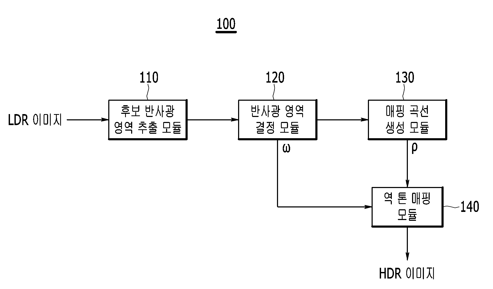
도 1에 도시된 바와 같이, 적어도 하나의 프로세서에 의해 제어되는 하이 다이내믹 레인지 이미지 생성 장치(이하, 설명의 편의를 위하여 'HDR 이미지 생성 장치'라 지칭함)(100)는 후보 반사광 영역 추출 모듈(110), 반사광 영역 결정 모듈(120), 매핑 곡선 생성 모듈(130), 그리고 역 톤 매핑 모듈(140)을 포함한다.As shown in FIG. 1, the high dynamic range image generating apparatus (hereinafter, referred to as an 'HDR image generating apparatus' for convenience of description) 100 controlled by at least one processor is a candidate reflection light
후보 반사광 영역 추출 모듈(110)은 외부로부터 복수의 픽셀을 가지는 로우 다이나믹 레인지(Low Dynamic Range) 이미지(이하, 설명의 편의를 위하여 'LDR 이미지'라 지칭함)를 수신하면, LDR 이미지에서 반사광 영역이 될 확률이 높은 후보 영역을 탐색한다. When the candidate reflected light
LDR 이미지에서 후보 반사광 영역을 탐색하기 위해, 후보 반사광 영역 추출 모듈(110)은 입력된 LDR 이미지로부터 선형적인 빛 정보를 복원한다. 선형적인 빛 정보를 복원하기 위해 후보 반사광 영역 추출 모듈(110)은 감마 역변환(gamma decoding)을 수행하는데, 감마 역변환에 대한 사항은 이미 알려진 내용으로 본 발명의 실시예에서는 상세한 설명을 생략한다.To search for the candidate reflected light region in the LDR image, the candidate reflected light
그리고, 후보 반사광 영역 추출 모듈(110)은 감마 역변환을 수행하여 감마 역변환 이미지를 생성하면, 감마 역변환 이미지에 복수의 픽셀 각각에 대한 감마 역변환 이미지 RGB 데이터를 생성하고, 이를 토대로 복수의 픽셀 각각에 대하여 반사광의 반사도를 정의한다. 여기서 모든 픽셀 각각에 생성된 감마 역변환 이미지 RGB 데이터는 해당 픽셀의 R값, G값, B값을 포함하고 있다. In addition, when the candidate reflection light
후보 반사광 영역 추출 모듈(110)은 복수의 픽셀로 구성된 감마 역변환 이미지로부터 무반사광 이미지를 생성하고, 무반사광 이미지의 RGB 데이터를 생성한다. 여기서 무반사광 이미지를 구성하는 모든 픽셀 각각에 생성된 무반사광 이미지의 RGB 데이터는 해당 픽셀의 R값, G값, B값을 포함하고 있다.The candidate reflected light
후보 반사광 영역 추출 모듈(110)은 감마 역변환 이미지의 RGB 데이터 평균(이하, 설명의 편의를 위하여 '제1 RGB 데이터 평균'이라 지칭함), 무반사광 영상의 RGB 데이터 평균(이하, 설명의 편의를 위하여 '제2 RGB 데이터 평균'이라 지칭함), 반사광의 반사도 평균을 계산한다. 후보 반사광 영역 추출 모듈(110)은 제1 RGB 데이터 평균과 제2 RGB 데이터 평균을 이용하여 초기 후보 반사광 영역을 검출한다. The candidate reflected light
그리고 후보 반사광 영역 추출 모듈(110)은 검출한 초기 후보 반사광 영역과 반사광의 반사도 평균을 이용하여 LDR 이미지에 대한 후보 반사광 영역을 추출한다.The candidate reflected light
반사광 영역 결정 모듈(120)은 후보 반사광 영역 추출 모듈(110)이 탐색한 후보 반사광 영역으로부터 대표 값을 복수 개 가지는 히스토그램을 생성한다. 후보 반사광 영역에서 히스토그램을 생성하는 방법은 다양한 방법으로 실행될 수 있으므로, 본 발명의 실시예에서는 어느 하나의 방법으로 한정하지 않는다. 그리고 후보 반사광 영역 추출 모듈(110)에서 정의한 반사광의 반사도의 평균에 따라, 반사광 영역을 검출하기 위한 반사도 평균에 적응적인 기준 값(adaptive threshold)(이하 설명의 편의를 위하여 '적응적 기준 값'이라 지칭함)을 계산한다.The reflected light
반사광 영역 결정 모듈(120)은 적응적 기준 값을 계산하면, 후보 반사광 영역에서 적응적 기준 값 이상의 값을 가진 영역을 반사광 영역으로 검출한다. 그리고 HDR 이미징을 위하여 반사광 영역을 결정하는 적응적 기준 값을 휘도 기반 데이터로 변경한다. 여기서 적응적 기준 값을 휘도 기반 데이터로 변경하는 방법은 다양한 방법으로 수행할 수 있으므로, 본 발명의 실시예에서는 어느 하나의 방법으로 한정하지 않는다. When the reflected light
반사광 영역 결정 모듈(120)은 검출한 반사광 영역과 휘도 기반 데이터를 매칭하여, 반사광과 확산광을 나누는 기준값인 반사광 구분 휘도 값을 획득한다. 본 발명의 실시예에서는 설명의 편의를 위하여 반사광 구분 휘도 값을 LDR 휘도 경계값(ω)이라 지칭하나, 반드시 이와 같이 한정되는 것은 아니다. The reflected light
반사광 영역 결정 모듈(120)은 획득한 LDR 휘도 경계값(ω)을 이용하여 반사광 영역에서 휘도 기반의 반사광 영역을 추출한다. 여기서, 반사광 영역 결정 모듈(120)이 LDR 휘도 경계값(ω)을 획득하는 방법이나 LDR 휘도 경계값(ω)을 이용하여 반사광 영역에서 휘도 기반 반사광 영역을 추출하는 방법은 여러 방법으로 수행할 수 있으므로, 본 발명의 실시예에서는 어느 하나의 방법으로 한정하지 않는다.The reflected light
매핑 곡선 생성 모듈(130)은 반사광 영역 결정 모듈(120)이 반사광 영역을 검출하면, 제1 LDR-HDR 휘도 변환 그래프를 생성한다. 제1 LDR-HDR 휘도 변환 그래프는 LDR 휘도 경계값(ω)과 동일한 값을 초기 HDR 휘도 경계값(ρ0)으로 가지도록 매핑된 그래프인 것을 예로 하여 설명하나, 매핑 값이 반드시 LDR 휘도 경계값과 동일할 필요는 없다. The mapping
그리고 반사광 영역 결정 모듈(120)이 검출한 확산광 영역의 평균 휘도를 계산한다. 여기서, 확산광 영역은 LDR 이미지에서 LDR 휘도 경계값(ω)보다 작은 값을 가지는 영역을 의미한다.The reflected light
매핑 곡선 생성 모듈(130)은 확산광 영역에 속하는 모든 픽셀들의 밝기 값을 더해주고, 확산광 영역에 속하는 픽셀 수로 나누어 평균 휘도를 계산한다. 평균 휘도를 계산한 매핑 곡선 생성 모듈(130)은 사람의 인지적 능력을 고려하기 위해 지역 적응 망막 반응 값(local adaptation retina response)을 이용하여, HDR 휘도 경계값이 포함될 HDR 휘도 범위를 결정한다.The mapping
여기서, 지역 적응 망막 반응 값은 빛의 강도, 적응 값, 망막 반응 민감도 결정 계수, 반응 최대 값을 이용하여 계산된다. 본 발명의 실시예에서는 반응 최대 값은 1로 설정하는 것을 예로 하여 설명하나, 반드시 이와 같이 한정되는 것은 아니다. Here, the regional adaptive retinal response value is calculated using light intensity, adaptive value, retinal response sensitivity determination coefficient, and response maximum value. In the embodiment of the present invention, the reaction maximum value is set to 1 as an example, but is not necessarily limited thereto.
그리고, HDR 휘도 경계값이라 함은 LDR 휘도 경계값 대비 LDR-HDR 휘도 변환 그래프에서 확산광 영역의 기울기와 반사광 영역의 기울기를 변화시키는, 그래프의 꺽은 점의 위치를 결정하기 위한 값을 의미한다. 여기서, 지역 적응 망막 반응 값을 사용하는 것은, 인간의 시각이 영상에서 배경 빛의 강도가 달라짐에 따라 비배경 부분인 지역적 반사광 영역에 대한 인지적 밝기가 달라지는 것을 고려하기 위함이다.In addition, the HDR luminance boundary value means a value for determining the position of a broken point of the graph which changes the slope of the diffused light region and the slope of the reflected light region in the LDR-HDR luminance conversion graph with respect to the LDR luminance boundary value. . Here, the local adaptive retinal response value is used to consider the cognitive brightness of the local reflected light region, which is a non-background part, as the human vision changes the intensity of the background light in the image.
이와 같이 확산광 영역의 지역 적응 망막 반응 값을 이용하면, 지역적 영역에서 사람이 느끼는 밝기의 정도를 고려할 수 있다. 적응적인 지역적 망막 반응 값을 이용하여 HDR 휘도 경계값을 계산하는 방법은 다양하나, 본 발명의 실시예에서는 지역적 영역의 평균 밝기를 이용한다. By using the regional adaptive retinal response value in the diffuse light region as described above, the degree of brightness that a human feels in the local region can be considered. There are various methods for calculating the HDR luminance threshold using adaptive regional retinal response values, but embodiments of the present invention use the average brightness of the local region.
매핑 곡선 생성 모듈(130)은 반사광 영역의 평균 휘도와 확산광 영역의 평균 휘도를 포함하는 이미지 정보와 인지적 특성을 고려하여, HDR 휘도 경계값의 범위를 결정한다. 그리고, 베버 상수를 이용하여 지역적 HDR 휘도 경계값을 결정한다. 매핑 곡선 생성 모듈(130)은 지역적 HDR 휘도 경계값을 결정한 후, 디스플레이 장치의 출력 휘도와 베버의 법칙에 따라 결정되는 상수를 고려하여 지역적 HDR 휘도 경계값을 보정한 후, LDR 휘도 경계값(ω)에 대응하는 최종 HDR 휘도 경계값(ρ)을 결정한다. The mapping
여기서, 베버의 법칙은 자극을 받고 있는 감각기에서 자극의 크기가 변화된 것을 느끼려면, 현재 자극에 대하여 일정 비율 이상의 차이가 나는 자극을 주어야 한다는 법칙이다. 베버에 법칙에 따르면, 처음에 약한 자극을 주면 자극의 변화가 적어도 그 변화를 쉽게 감지할 수 있으나, 처음에 강한 자극을 주면 자극의 변화를 감지하는 능력이 약해져서 더 큰 자극에서만 변화를 느낄 수 있다.Here, Weber's law is that in order to feel the change in the magnitude of the stimulus in the sensory sensor that is being stimulated, it is necessary to give a stimulus that differs by a certain percentage from the current stimulus. According to Weber's law, if a weak stimulus is initially applied, the change in the stimulus can be easily detected at least, but a strong stimulus at first weakens the ability to detect a change in the stimulus and can only feel the change in the larger stimulus. .
즉, 현재 자극과 그 다음에 주어지는 자극의 세기간의 차이가 일정한 비율 이상이 되어야만 그 자극의 변화량을 감각기가 느낄 수 있다. 이때의 비율을 베버 상수로 정의할 수 있다.That is, the amount of change in the stimulus can be sensed only when the difference between the current stimulus and the next given stimulus intensity is greater than or equal to a certain ratio. The ratio at this time can be defined as Weber constant.
역 톤 매핑 모듈(140)은 매핑 곡선 생성 모듈(130)에서 계산한 LDR 휘도 경계값(ω)과 HDR 휘도 경계값(ρ)을 이용하여 LDR-HDR 휘도 변환 그래프의 기울기가 변경될 점의 위치를 확인하여 초기 LDR-HDR 휘도 변환 그래프를 변형한 후, 변형된 LDR-HDR 휘도 변환 그래프에 따라 LDR 이미지의 LDR 휘도 경계값을 HDR 휘도 경계값으로 역 톤 매핑한다. The inverse
즉, 역 톤 매핑 모듈(140)은 매핑 곡선을 변환하기 위해 확산광 영역의 평균 휘도(average luminance)를 사용하여, LDR 이미지에서 확산광 영역의 계조를 수정한다. 그리고 LDR 이미지에서 반사광 영역의 지각적 밝기(perceptual brightness)를 고려하여 전체 LDR 이미지의 계조를 보정한다. That is, the inverse
이상에서 설명한 HDR 이미지 생성 장치(100)를 이용하여 역 톤 매핑을 수행하여 HDR 이미지를 생성하는 방법에 대해 도 2 내지 도 7b를 참조로 설명한다.A method of generating an HDR image by performing inverse tone mapping using the HDR
도 2는 본 발명의 실시예에 따른 하이 다이내믹 레인지 이미지 생성 방법에 대한 흐름도이다.2 is a flowchart illustrating a method of generating a high dynamic range image according to an exemplary embodiment of the present invention.
도 2에 도시된 바와 같이, HDR 이미지 생성 장치(100)의 후보 반사광 영역 추출 모듈(110)은 복수의 픽셀들로 구성된 단일 노출 이미지인 LDR 이미지를 수신하면(S100), 수신한 입력 이미지에서 후보 반사광 영역을 추출한다(S200). 후보 반사광 영역을 추출하는 절차에 대해 도 3a 및 도 3b를 참조하여 먼저 설명한다. As illustrated in FIG. 2, when the candidate reflection light
도 3a 및 도 3b는 본 발명의 실시예에 따른 후보 반사광 영역 추출 방법에 대한 흐름도 및 예시도이다.3A and 3B are a flowchart and an exemplary view of a method for extracting candidate reflected light regions according to an embodiment of the present invention.
도 3a에 도시된 바와 같이, HDR 이미지 생성 장치(100)의 후보 반사광 영역 추출 모듈(110)은 LDR 이미지에서 선형적인 빛 정보를 복원하기 위해 다음 수학식 1과 같이 수신한 LDR 이미지에 감마 역변환을 진행하여 감마 역변환 이미지를 생성한다(S201).As shown in FIG. 3A, the candidate reflected light

여기서 I'R, I'G, I'B는 감마 변환(gamma encoding)이 적용되어 있는 이미지의 R, G, B 채널을 의미하고, ![]()
![]()
후보 반사광 영역 추출 모듈(110)이 수신한 LDR 이미지에 감마 역변환을 수행하면, 도 3b의 (①)에 나타낸 바와 같이 감마 역변환 이미지가 생성된다. 후보 반사광 영역 추출 모듈(110)은 감마 역변환 이미지에 포함된 모든 픽셀 각각에 대하여 역변환 이미지 RGB 데이터를 생성한다. 후보 반사광 영역 추출 모듈(110)은 모든 픽셀 각각에 대해, R, G, B 값을 비교한다. When the candidate reflected light
그리고 후보 반사광 영역 추출 모듈(110)은 R, G, B 값 중 최소 값을 해당 픽셀에 대한 반사광의 반사도로 정의한다(S202). 예를 들어, 감마 역변환 이미지에서 임의의 픽셀에 대한 R, G, B 값이 (100, 50, 50)인 경우를 예로 하면, 해당 임의의 픽셀에 대한 반사광의 반사도는 50이 된다.The candidate reflected light
후보 반사광 영역 추출 모듈(110)은 모든 픽셀에 대하여 반사광의 반사도를 결정하면, 결정된 반사도를 이용하여 감마 역변환 이미지로부터 생성한 무반사광(specular free) 이미지에서 모든 픽셀에 대한 무반사광 이미지의 RGB 데이터를 생성한다(S203). 여기서, 무반사광 이미지는 도 3b의 (②)에 도시한 바와 같으며, 무반사광 이미지는 다음 수학식 2와 같이 정의할 수 있다.The candidate reflected light

이때, Sγ 은 반사광의 반사도이고, Isf _RGB는 무반사광 이미지를 의미한다.In this case, S γ is the reflectivity of the reflected light, and I sf _ RGB means the non-reflected light image.
반사광의 반사도와 무반사광의 이미지가 생성되면, 후보 반사광 영역 추출 모듈(110)은 감마 역변환 이미지로부터 제1 RGB 데이터의 평균을 구하고, 무반사광 이미지로부터 제2 RGB 데이터의 평균을 구한다. 그리고 복수의 픽셀 수만큼 결정된 반사광의 반사도의 평균을 구한다. 제1 RGB 데이터의 평균(Iavg), 제2 RGB 데이터의 평균(Isf_avg), 그리고 반사도의 평균(![]()
![]()
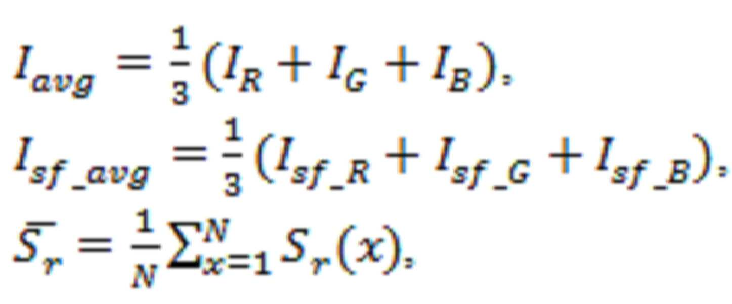
여기서 N은 이미지의 총 픽셀 수를 의미한다.Where N is the total number of pixels in the image.
후보 반사광 영역 추출 모듈(110)은 수학식 3을 통해 구한 제1 RGB 데이터 평균과 제2 RGB 데이터 평균의 차이를 이용하여 도 3b의 (③)와 같이 초기 후보 반사광 영역을 구한다(S204). 그리고 후보 반사광 영역 추출 모듈(110)은 초기 후보 반사광 영역에서 반사광의 반사도 평균 값의 차를 구한다. The candidate reflection light
초기 후보 반사광 영역에서 반사도 평균 값의 차를 구하면 초기 후보 반사광 영역에서 확산광 영역이 사라지게 되고, 도 3b (④)에 도시한 바와 같이 초기 후보 반사광 영역에서 반사광의 반사도 평균 값 이상의 영역만이 검출된다. 이 영역을 후보 반사광 영역으로 정의한다(S205). 이때, 후보 반사광 영역(SHcand)은 다음 수학식 4로 계산할 수 있다. When the difference between the reflectance average values is obtained in the initial candidate reflected light region, the diffused light region disappears in the initial candidate reflected light region, and as shown in FIG. . This region is defined as a candidate reflected light region (S205). In this case, the candidate reflected light region SH cand may be calculated by the following Equation 4.
![]()
![]()
S205 단계에서와 같이 후보 반사광 영역이 추출되면, HDR 이미지 생성 장치(100)의 반사광 영역 결정 모듈(120)은 상기 도 2에 도시한 바와 같이 적응적으로 반사광 영역을 결정한다(S300). 반사광 영역 결정 모듈(120)이 적응적으로 반사광 영역을 결정하는 절차에 대해 도 4a 및 도 4b의 도면을 참조로 하여 먼저 설명한다. When the candidate reflected light region is extracted as in step S205, the reflected light
도 4a 및 도 4b는 본 발명의 실시예에 따른 반사광 영역을 결정하는 방법에 대한 흐름도 및 예시도이다.4A and 4B are a flowchart and an exemplary view of a method of determining a reflected light region according to an embodiment of the present invention.
본 발명의 실시예에서는 후보 반사광 영역에서 반사광 영역을 검출하는 기법은 종래와 같이 기준값을 하나의 값으로 결정하는 것이 아니라, 후보 반사광 영역의 반사도에 적응적으로 기준값을 설정하는 것을 고려한다. In the embodiment of the present invention, the technique of detecting the reflected light region in the candidate reflected light region does not determine the reference value as one value as in the related art, but considers setting the reference value adaptively to the reflectivity of the candidate reflected light region.
따라서, 반사광 영역 결정 모듈(120)은 상기 도 3a의 S205 단계에서 후보 반사광 영역 추출 모듈(110)이 추출한 후보 반사광 영역으로부터 도 4a 및 도 4b-1과 같이 후보 반사광 영역으로부터 복수의 대표 값을 가지는 히스토그램을 생성한다(S301). 히스토그램을 생성한 후, 반사광 영역 결정 모듈(120)은 반사광 영역을 결정하기 위한 적응적 기준 값을 계산한다(S302). Accordingly, the reflected light
여기서, 적응적 기준 값이라 함은, 후보 반사광 영역에서 반사도의 평균이 계산된 값보다 낮다면 반사광 영역을 작게 검출하도록 하고, 반사도의 평균이 계산된 값보다 높다면 반사광 영역을 크게 검출할 수 있도록 하는 반사도 평균에 따라 조정될 수 있는 기준 값을 의미한다. 적응적 기준 값(TH)은 다음 수학식 5를 통해 정의한다.Here, the adaptive reference value means that if the average of the reflectance in the candidate reflected light region is lower than the calculated value, the reflected light region is detected to be smaller, and if the average of the reflectance is higher than the calculated value, the reflected light region can be detected. The reflectance means a reference value that can be adjusted according to the average. The adaptive reference value TH is defined through
![]()
![]()
여기서 Sth는 ![]()
![]()
![]()
![]()
반사광 영역을 결정하는 적응적 기준 값을 결정하면, 반사광 영역 결정 모듈(120)은 적응적 기준 값을 이용하여 후보 반사광 영역에서 반사광 영역을 결정한다(S303). 그리고 나서, 역 톤 매핑 기반 HDR 이미징을 위해, 적응적 기준 값을 휘도 기반 데이터로 변경한다(S304). When the adaptive reference value for determining the reflected light region is determined, the reflected light
즉, 도 4b-2에 도시된 바와 같이, 반사광 영역 결정 모듈(120)은 이미지에서 반사광 영역과 휘도 기반 이미지를 지역 매칭을 이용하여 검출한다. 여기서, 반사광 영역 결정 모듈(120)은 입력 영상의 밝기와 디스플레이 휘도가 비례하다고 가정하고, 적응적 기준 값을 휘도 기반 데이터로 변경한다. That is, as illustrated in FIG. 4B-2, the reflected light
반사광 영역 결정 모듈(120)이 적응적 기준 값으로 반사광 영역을 결정하는 방법이나, 적응적 기준 값을 휘도 기반 데이터로 변경하는 방법은 다양한 방법으로 수행할 수 있다. 그러나, 본 발명의 실시예에서는 다음 수학식 6 및 7을 이용하여 적응적 기준 값 이상의 반사광 영역(SHfinal)을 결정하고, 적응적 기준 값을 휘도 기반 데이터로 변경하는 것을 예로 하여 설명한다.The reflected light
![]()
![]()

수학식 6에서 SHfinal은 적응적 기준 값 이상의 반사광 영역을 의미한다. In
수학식 7에서 α는 디스플레이의 최대 휘도이고, Iγ는 R, G, B 이미지의 밝기(IR, IG, IB)를 휘도 기반 이미지로 변환한 결과이다.In
반사광 영역 결정 모듈(120)은 검출한 반사광 영역과 휘도 기반 데이터를 매칭하여, LDR 이미지에서 반사광과 확산광을 나누는 기준값인 LDR 휘도 경계값(ω)을 획득한다(S305). 그리고 획득한 LDR 휘도 경계값(ω)을 이용하여, 휘도 기반의 반사광 영역을 추출한다. 여기서 LDR 휘도 경계값(ω)은 다음 수학식 8과 같이 정의한다.The reflected light
![]()
![]()
S305 단계에서 LDR 휘도 경계값(ω)을 획득하면, 매핑 곡선 생성 모듈(130)은 초기 LDR-HDR 휘도 변환 그래프를 생성하는 절차를 수행한다(S400). 이에 대해 도 5a 내지 도 5d를 참조로 하여 함께 설명한다. When the LDR luminance boundary value (ω) is obtained in operation S305, the mapping
도 5a 내지 도 5d는 본 발명의 실시예에 따른 초기 LDR-HDR 휘도 변환 그래프 생성 방법에 대한 흐름도 및 예시도이다.5A to 5D are flowcharts and exemplary diagrams of a method for generating an initial LDR-HDR luminance conversion graph according to an embodiment of the present invention.
도 5a에 도시된 바와 같이, 매핑 곡선 생성 모듈(130)은 반사광 영역 결정 모듈(120)이 LDR 휘도 경계값(ω)으로 기준 값을 변경하면, 사람의 인지적 능력을 고려하기 위해 적응적인 지역적 망막 반응을 사용하여 출력 매핑 값의 범위 즉, 도 5b에 도시한 Y축인 출력 휘도(Output luminance)의 기준을 정해, LDR 휘도 경계값(ω)에 대응되는 HDR 휘도 경계값을 어떻게 선택할지를 결정한다. As shown in FIG. 5A, the mapping
이때, 매핑 곡선 생성 모듈(130)은 반사광 영역 결정 모듈(120)이 결정한 LDR 휘도 경계값(ω)과 동일한 값이 LDR 휘도 경계값(ω)에 대응하는 초기 HDR 휘도 경계값(ρ0)에 매핑되도록 LDR-HDR 휘도 변환 그래프를 도 5b의 좌측 그래프와 같이 생성한다.At this time, the mapping
여기서, 인지적 능력을 고려하는 적응적 반응은 수학식 9를 이용하여 계산한다.Here, the adaptive response considering the cognitive ability is calculated using
![]()
![]()
여기서, R은 망막 반응, Rmax는 반응의 최대값, L은 빛의 강도를 의미한다. σ은 적응 값, n은 망막 반응의 민감도를 결정하는 계수를 의미한다.Where R is the retinal reaction, R max is the maximum value of the reaction, and L is the intensity of light. σ is an adaptation value and n is a coefficient that determines the sensitivity of the retinal response.
구체적으로 지역 적응 망막 반응 값을 이용하면, 지역적 영역에서 사람이 느끼는 밝기의 정도를 고려할 수 있다. 즉, 도 5c에 도시된 바와 같이, 인간의 시각이 배경 밝기 정도가 달라짐에 따라 인지적 밝기 정도가 달라짐을 알 수 있다. 도 5c의 제1 그래프(①), 제2 그래프(②), 제3 그래프(③)는 각각의 적응 정도가 변화했을 때, 지역 적응 망막 반응의 변화를 나타낸 것이다.Specifically, by using a local adaptive retinal response value, it is possible to consider the degree of brightness that a person feels in a local area. That is, as shown in FIG. 5C, it can be seen that the degree of cognitive brightness varies as the degree of background brightness of the human vision changes. The first graph (1), the second graph (2), and the third graph (3) in FIG. 5C show changes in the regional adaptive retinal response when the degree of adaptation changes.
이와 같이, 매핑 곡선 생성 모듈(130)은 지역 적응 망막 반응 값을 사용하여 반사광 영역 결정 모듈(120)이 결정한 반사광 영역이 사람에게 어떻게 인지되는지 분석하고, 분석 결과를 가지고 HDR 휘도 경계값 범위를 결정한다. 이를 위해, 매핑 곡선 생성 모듈(130)은 LDR 이미지에서 LDR 휘도 경계값(ω)보다 작은 값을 가지는 영역인 확산광 영역의 평균 휘도를 계산한다. 그리고 나서, 다음 수학식 10을 이용하여 HDR 휘도 경계값의 범위를 결정한다.As such, the mapping
![]()
![]()
여기서, ![]()
![]()
![]()
![]()
기존에는 적응적인 값을 계산하는 기법이 많으나, 본 발명의 실시예에서는 도 5d에 도시한 바와 같이 지역적 영역의 평균 밝기를 이용하는 기법을 사용하는 기법을 사용한다. 이를 위해, 먼저 매핑 곡선 생성 모듈(130)은 확산광 영역의 평균 휘도를 계산한다(S401). 즉, 매핑 곡선 생성 모듈(130)은 확산광 영역에 속하는 모든 픽셀들의 밝기 값을 더해주고, 확산광 영역에 속하는 픽셀 수로 나누어 평균 휘도를 계산한다.Conventionally, there are many techniques for calculating adaptive values, but the embodiment of the present invention uses a technique using a technique using average brightness of a local area as shown in FIG. 5D. To this end, the mapping
그리고 반사광 영역이 사람에게 어떠한 밝기로 느껴지는지 계산하기 위하여, 이미지 정보와 인지적 특성을 고려하는 지역 적응 망막 반응 값을 이용하여, HDR 휘도 경계값의 범위를 계산한다(S402). HDR 휘도 경계값의 범위는 이후 설명할 수학식 11의 ρ_max와 ρ_min을 이용하여 정의된다.In order to calculate what brightness the reflected light region feels to a human, a range of HDR luminance boundary values is calculated using a local adaptive retinal response value considering image information and cognitive characteristics (S402). The range of the HDR luminance boundary value is defined using p_max and p_min in Equation 11 to be described later.
그리고, 매핑 곡선 생성 모듈(130)은 베버 상수를 이용하여 지역적 HDR 휘도 경계값을 결정한다(S403). 여기서, 지역적 HDR 휘도 경계값은 디스플레이 장치의 출력 휘도와 베버 상수를 고려하여 결정한다. The mapping
이상의 절차를 통해 출력 휘도 범위와 지역적 출력 휘도 값이 결정되면, 매핑 곡선 생성 모듈(130)은 최종 매핑 곡선을 결정하는 절차를 수행한다. 이에 대해 도 6a 및 도 6b를 참조로 함께 설명한다. When the output luminance range and the local output luminance value are determined through the above procedure, the mapping
도 6a 및 도 6b는 본 발명의 실시예에 따른 최종 LDR-HDR 휘도 변환 그래프 생성 방법에 대한 흐름도 및 예시도이다.6A and 6B are a flowchart and an exemplary view of a method for generating a final LDR-HDR luminance conversion graph according to an embodiment of the present invention.
상기 S400 단계를 통해 적응적인 지역적 망막 반응만 고려하여 최소 HDR 휘도 경계값으로 최종 HDR 휘도 경계값을 결정하게 될 경우, 반사광 영역의 범위가 너무 넓어져 확산광 영역의 계조 표현력이 저하되고 전체 이미지의 인지적 화질이 저하될 수 있다. 따라서, 본 발명의 실시예에서는 이미지를 디스플레이 하는 디스플레이 장치의 출력 휘도와 지역적 영역의 인지적 대조비를 고려하는 베버 상수를 통해, HDR 휘도 경계값을 보정하고 보정된 값을 최종 HDR 휘도 경계값으로 사용하고자 한다. If the final HDR luminance boundary value is determined as the minimum HDR luminance boundary value by considering only the adaptive local retinal response through the step S400, the range of the reflected light region becomes too wide, thereby decreasing the gray scale expressing power of the diffuse image region and Cognitive image quality may be degraded. Therefore, in the exemplary embodiment of the present invention, the HDR luminance boundary value is corrected and the corrected value is used as the final HDR luminance boundary value through the Weber constant considering the output luminance of the display device displaying the image and the cognitive contrast ratio of the local area. I would like to.
이를 위해 매핑 곡선 생성 모듈(130)은 수학식 11을 이용하여 HDR 휘도 경계값에 대한 범위의 최소 값과 최대 값, 그리고 후보 HDR 휘도 경계값을 정의한다(S601).To this end, the mapping
![]()
![]()
여기서, ![]()
![]()
![]()
![]()
S601 단계에서 매핑 곡선 생성 모듈(130)이 정의한 매핑 범위의 최소 값과 최대 값, 후보 HDR 휘도 경계값에 대한 개념과 역 톤 매핑 기반 HDR 이미징 곡선은 도 6b에 도시한 바와 같다.The concept of the minimum and maximum values of the mapping range, the candidate HDR luminance boundary values, and the inverse tone mapping based HDR imaging curve defined by the mapping
S601 단계에 의해 후보 매핑 값이 정의되면, 매핑 곡선 생성 모듈(130)은 수학식 12에 나타낸 베버 상수 기반의 식을 이용하여 반사광 영역의 베버 상수(SHwe)와 확산광 영역의 베버 상수(DFwe)를 계산한다.When the candidate mapping value is defined in step S601, the mapping

여기서, Sapl은 반사광 영역의 평균 휘도를 의미한다. Here, S apl means the average luminance of the reflected light region.
그리고, 수학식 13과 같이 후보 HDR 휘도 경계값을 변화시키며, 반사광 영역의 베버 상수(SHwe)와 확산광 영역의 베버 상수(DFwe)가 같아질 때의 후보 출력 휘도 값을 최종 HDR 휘도 경계값(ρ_final)으로 설정한다(S502).Then, as shown in Equation 13, the candidate HDR luminance boundary value is changed, and the candidate output luminance value when the Weber constant SHwe of the reflected light region is equal to the Weber constant DFwe of the diffused light region is equal to the final HDR luminance boundary value ( r_final) (S502).
![]()
![]()
여기서, 수학식 13의 조건문을 토대로 수학식 14를 도출할 수 있다.Here, Equation 14 may be derived based on the conditional statement of Equation 13.
![]()
![]()
이상의 절차를 통해 LDR 휘도 경계값과 최종 HDR 휘도 경계값이 정의되면, 역 톤 매핑 모듈(140)은 매핑 곡선 생성 모듈(130)에서 S110 단계에서 계산한 LDR 휘도 경계값과 HDR 휘도 경계값을 토대로 LDR 이미지를 역 톤 매핑한다. 이에 대해 도 7a 및 7b를 참조로 설명한다.When the LDR luminance boundary value and the final HDR luminance boundary value are defined through the above procedure, the inverse
도 7a 및 도 7b는 본 발명의 실시예에 따른 역 톤 매핑 기반 HDR 이미징 곡선을 생성하는 방법에 대한 흐름도 및 예시도이다. 7A and 7B are a flowchart and an exemplary view of a method for generating an inverse tone mapping based HDR imaging curve according to an embodiment of the present invention.
도 7a에 도시한 바와 같이 역 톤 매핑 모듈(140)은 확산광 영역의 평균 휘도를 이용하여 곡선을 변형한다(S601). 즉, 도 7b에 나타낸 바와 같이 확산광 영역의 평균 휘도를 이용하여 곡선을 변형한다.As shown in FIG. 7A, the inverse
그리고 다음 수학식 15를 이용하여 역 톤 매핑을 적용한 후 HDR 이미지를 생성한다(S602).In operation S602, an inverse tone mapping is applied using the following Equation 15 to generate an HDR image.

여기서, ![]()
![]()
![]()
![]()
![]()
![]()
이상에서 설명한 본 발명의 실시예에 따른 방법으로 생성하는 HDR 이미지와 종래 방법으로 생성한 HDR 이미지를 비교하는 예에 대해 도 8을 참조로 설명한다.An example of comparing the HDR image generated by the method according to the embodiment of the present invention described above with the HDR image generated by the conventional method will be described with reference to FIG. 8.
도 8은 본 발명의 실시예에 따라 생성된 HDR 이미지와 종래 방법으로 생성한 HDR 이미지를 비교한 예시도이다.8 is an exemplary diagram comparing an HDR image generated according to an embodiment of the present invention with an HDR image generated by a conventional method.
도 8에서는 다중 노출 기반 방법을 사용하여 TMO의 결과, 탐지지도의 확률, VDP(Visual Difference Predictor) 품질 스코어 및 DRIM(Dynamic Range-Independent Metric)을 실제 HDR 이미지와 함께 나타내었다. 먼저 도 8의 (a)에 나타난 바와 같이, 영역 기반 방법(②)은 정반사 탐지 성능이 상대적으로 좋지 않기 때문에 반사 영역에서 높은 오류 확률을 보인다. 또 다른 종래 방법인 맵핑 커브 방법(③)은 맵핑 커브가 포화된 영역의 계조를 저하시키기 때문에 포화 된 영역에서 높은 오류 확률을 보였다. 영상 통계에 기반한 감마 확장 방법(④)은 영역 정보를 고려하지 않았기 때문에, 높은 오류 확률이 관찰되는 많은 영역을 가진다. In FIG. 8, the results of the TMO, the probability of the detection map, the Visual Difference Predictor (VDP) quality score, and the dynamic range-independent metric (DRIM) using the multiple exposure-based method are shown along with the actual HDR image. First, as shown in (a) of FIG. 8, the region-based
본 발명의 실시예에 따른 방법(①)을 이용하면, 높은 오류 확률 영역은 경미한 영역의 지각 밝기와 베버(weber) 대비에 기반한 곡선의 균일 성을 고려하여 상대적으로 좁게 나타난다. 또한 DRIM 결과는 본 발명의 실시예에 따른 방법이 경면 영역의 경계에서 녹색 점의 수가 적어, 로컬 적응을 사용하여 자연스럽게 입력 범위가 확장되었음을 알 수 있다. Using the
도 8의 (b)와 (c)는 입력 이미지가 전반적으로 밝을 때의 결과를 보여준다. 이 경우, 본 발명의 실시예에 따른 방법에서 경면 영역의 매핑 곡선 기울기는 경면 영역의 상대적 휘도를 증가시키기 위해 편향되었다. 따라서, 밝은 영역에서의 차이 검출의 가능성이 감소되어, 고화질의 이미지가 생성되는 것을 알 수 있다. 또한, DRIM 결과는 본 발명의 실시예에 따른 방법이 다른 종래 방법보다 녹색 점의 수가 가장 적음을 나타낸다. 8 (b) and 8 (c) show the results when the input image is generally bright. In this case, in the method according to the embodiment of the present invention, the slope of the mapping curve of the mirrored area is biased to increase the relative brightness of the mirrored area. Thus, it can be seen that the possibility of difference detection in bright areas is reduced, so that a high quality image is generated. In addition, the DRIM results indicate that the method according to the embodiment of the present invention has the lowest number of green dots than other conventional methods.
이상에서 본 발명의 실시예에 대하여 상세하게 설명하였지만 본 발명의 권리범위는 이에 한정되는 것은 아니고 다음의 청구범위에서 정의하고 있는 본 발명의 기본 개념을 이용한 당업자의 여러 변형 및 개량 형태 또한 본 발명의 권리범위에 속하는 것이다.Although the embodiments of the present invention have been described in detail above, the scope of the present invention is not limited thereto, and various modifications and improvements of those skilled in the art using the basic concepts of the present invention defined in the following claims are also provided. It belongs to the scope of rights.
Claims (13)
상기 로우 다이내믹 레인지 이미지에서 반사광 영역을 검출하고, 상기 반사광 영역에 대하여 계산된 반사도가 평균 값 이상인 영역을 후보 반사광 영역으로 검출하고, 검출한 후보 반사광 영역에서 반사광 영역과 확산광 영역으로 구분하는 LDR 휘도 경계값을 결정하는 단계,
확산광 영역의 평균 휘도와 지역 적응 망막 반응 값을 고려하여 HDR 휘도 경계값 범위를 결정하고, 상기 결정한 HDR 휘도 경계값 범위 내에서 상기 확산광 영역의 평균 휘도와 반사광 영역의 평균 휘도를 이용하여 상기 LDR 휘도 경계값에 대응하는 최종 HDR 휘도 경계값을 결정하는 단계,
상기 LDR 휘도 경계값과 상기 최종 HDR 휘도 경계값을 토대로 초기 LDR-HDR 휘도 변환 그래프에서 확산광 영역의 기울기와 반사광 영역 기울기를 변형하는 단계, 그리고
기울기가 변형된 출력 LDR-HDR 휘도 변환 그래프를 기초로 상기 로우 다이내믹 레인지 이미지의 휘도를 변형하여, 상기 하이 다이내믹 레인지 이미지로 생성하는 단계
를 포함하는 하이 다이내믹 레인지 이미지 생성 방법.An image generating apparatus generates a high dynamic range image from one low dynamic range image,
LDR luminance is detected in the low dynamic range image, a region whose reflectivity calculated for the reflected light region is greater than or equal to an average value is detected as a candidate reflected light region, and the LDR luminance is divided into a reflected light region and a diffused light region in the detected candidate reflected light region. Determining a threshold,
The HDR luminance boundary value range is determined in consideration of the average luminance of the diffused light region and the local adaptive retinal response value, and the average luminance of the diffused light region and the average luminance of the reflected light region are determined within the determined HDR luminance boundary value range. Determining a final HDR luminance threshold corresponding to the LDR luminance threshold;
Modifying the slope of the diffused light region and the slope of the reflected light region in an initial LDR-HDR luminance conversion graph based on the LDR luminance boundary value and the final HDR luminance boundary value, and
Generating the high dynamic range image by modifying the luminance of the low dynamic range image based on an output LDR-HDR luminance conversion graph having a modified slope;
High dynamic range image generation method comprising a.
상기 LDR 휘도 경계값을 결정하는 단계는,
상기 로우 다이내믹 레인지 이미지를 감마 역변환하여 복수의 픽셀로 구성되는 감마 역변환 이미지로 생성하는 단계,
상기 복수의 픽셀 각각에 대한 RGB 데이터를 토대로 상기 복수의 픽셀 각각에 대하여 반사광의 반사도를 결정하는 단계,
상기 RGB 데이터와 상기 반사광의 반사도를 이용하여 복수의 픽셀로 구성되는 무반사광 이미지를 생성하는 단계, 그리고
상기 RGB 데이터로부터 구한 제1 RGB 데이터 평균, 상기 무반사광 이미지로부터 구한 제2 RGB 데이터 평균의 차이를 이용하여 상기 로우 다이내믹 레인지 이미지에서 초기 후보 반사광 영역을 구하는 단계
를 포함하는 하이 다이내믹 레인지 이미지 생성 방법.The method of claim 1,
Determining the LDR luminance boundary value,
Gamma inverse transforming the low dynamic range image to generate a gamma inverse transform image composed of a plurality of pixels;
Determining reflectance of reflected light for each of the plurality of pixels based on the RGB data for each of the plurality of pixels;
Generating an antireflection light image composed of a plurality of pixels using the RGB data and the reflectivity of the reflected light, and
Obtaining an initial candidate reflected light region in the low dynamic range image by using a difference between a first RGB data average obtained from the RGB data and a second RGB data average obtained from the non-reflected light image
High dynamic range image generation method comprising a.
상기 초기 후보 반사광 영역을 구하는 단계 이후에,
상기 반사광의 반사도 평균 값을 구하는 단계, 그리고
상기 초기 후보 반사광 영역에서 상기 반사도 평균 값 이상의 영역만을 상기 후보 반사광 영역으로 검출하는 단계
를 포함하는 하이 다이내믹 레인지 이미지 생성 방법.The method of claim 2,
After obtaining the initial candidate reflected light region,
Obtaining a reflectance average value of the reflected light, and
Detecting only the region of the initial candidate reflected light region having the reflectance average value or more as the candidate reflected light region.
High dynamic range image generation method comprising a.
상기 LDR 휘도 경계값을 결정하는 단계는,
상기 후보 반사광 영역으로부터 복수의 대표 값을 가지는 히스토그램을 생성하는 단계,
상기 후보 반사광 영역에서 반사광 영역을 결정하기 위하여, 후보 반사광 영역의 반사도의 평균에 적응적인 기준 값을 계산하는 단계, 그리고
상기 반사도의 평균에 적응적인 기준 값을 토대로 상기 후보 반사광 영역에서 반사광 영역을 결정하는 단계
를 포함하는 하이 다이내믹 레인지 이미지 생성 방법.The method of claim 2,
Determining the LDR luminance boundary value,
Generating a histogram having a plurality of representative values from the candidate reflected light region;
Calculating a reference value adaptive to an average of reflectances of the candidate reflected light region to determine the reflected light region in the candidate reflected light region, and
Determining a reflected light region in the candidate reflected light region based on a reference value adaptive to the average of the reflectivity
High dynamic range image generation method comprising a.
상기 LDR 휘도 경계값을 결정하는 단계는,
상기 반사도의 평균에 적응적인 기준 값을 휘도 기반 데이터로 변경하는 단계,
상기 반사광 영역과 상기 휘도 기반 데이터를 매칭하여, 상기 LDR 휘도 경계값을 결정하는 단계, 그리고
상기 반사광 영역에서 상기 LDR 휘도 경계값을 이용하여, 휘도 기반 반사광 영역을 추출하는 단계
를 포함하는 하이 다이내믹 레인지 이미지 생성 방법.The method of claim 4, wherein
Determining the LDR luminance boundary value,
Changing a reference value adaptive to the average of the reflectance into luminance based data,
Determining the LDR luminance boundary by matching the reflected light region with the luminance based data; and
Extracting a luminance-based reflected light region from the reflected light region using the LDR luminance boundary value
High dynamic range image generation method comprising a.
상기 최종 HDR 휘도 경계값을 결정하는 단계는,
상기 확산광 영역을 구성하는 복수의 픽셀들의 밝기 값과 픽셀 수를 이용하여 상기 확산광 영역의 평균 휘도를 계산하는 단계,
상기 확산광 영역의 평균 휘도, 상기 확산광 영역의 픽셀 수, 상기 지역 적응 망막 반응 값을 이용하여, 상기 LDR 휘도 경계값에 대응하여 상기 초기 LDR-HDR 휘도 변환 그래프의 기울기를 변형하기 위한 반사광 영역의 HDR 휘도 경계값 범위를 계산하는 단계, 그리고
상기 계산한 HDR 휘도 경계값 범위에 포함된 복수의 값들 베버의 법칙에 따라 결정되는 상수를 이용하여, 상기 HDR 휘도 경계값 범위에 해당하는 최소 HDR 휘도 경계값을 지역적 HDR 휘도 경계값으로 결정하는 단계
를 포함하는 하이 다이내믹 레인지 이미지 생성 방법.The method of claim 5,
Determining the final HDR luminance threshold value,
Calculating an average luminance of the diffused light region using brightness values of the plurality of pixels constituting the diffused light region and the number of pixels;
Reflected light region for modifying the slope of the initial LDR-HDR luminance conversion graph corresponding to the LDR luminance boundary value by using the average luminance of the diffused light region, the number of pixels of the diffused light region, and the region adaptive retinal response value Calculating a range of HDR luminance thresholds, and
Determining a minimum HDR luminance boundary value corresponding to the HDR luminance boundary value range as a local HDR luminance boundary value by using a constant determined according to the Weber's law.
High dynamic range image generation method comprising a.
상기 지역적 HDR 휘도 경계값으로 결정하는 단계 이후에,
HDR 휘도 경계값 범위의 최소 값과 최대 값, 그리고 후보 HDR 휘도 경계값을 정의하는 단계,
상기 반사광 영역에서 계산된 제1 값과 확산광 영역에서 계산된 제2 값이 같아지도록, 상기 후보 HDR 휘도 경계값을 변경하는 단계,
상기 제1 값과 제2 값이 같아질 때의 HDR 휘도 경계값을 상기 최종 HDR 휘도 경계값으로 설정하는 단계
를 포함하는 하이 다이내믹 레인지 이미지 생성 방법.The method of claim 6,
After determining the regional HDR luminance threshold,
Defining a minimum and a maximum value of the HDR luminance threshold range and a candidate HDR luminance threshold value,
Changing the candidate HDR luminance boundary value such that the first value calculated in the reflected light region and the second value calculated in the diffused light region are equal;
Setting the HDR luminance boundary value when the first value and the second value are equal to the final HDR luminance boundary value
High dynamic range image generation method comprising a.
상기 제1 값은 반사광 영역의 평균 휘도와 후보 HDR 휘도 경계값을 이용하여 계산되는 값이고,
상기 제2 값은 확산광 영역의 평균 휘도와 후보 HDR 휘도 경계값을 이용하여 계산되는 값인 하이 다이내믹 레인지 이미지 생성 방법.The method of claim 7, wherein
The first value is a value calculated using the average luminance of the reflected light region and the candidate HDR luminance boundary value.
And the second value is a value calculated using an average luminance of a diffused light region and a candidate HDR luminance boundary value.
상기 반사광 영역 기울기를 변형하는 단계는,
상기 LDR 휘도 경계값과, 상기 LDR 휘도 경계값에 대응하는 최종 HDR 휘도 경계값을 이용하여, 상기 확산광 영역의 계조가 보정되도록 상기 초기 LDR-HDR 휘도 변환 그래프를 변형하는 단계
를 포함하는 하이 다이내믹 레인지 이미지 생성 방법.The method of claim 8,
The step of modifying the reflected light area slope,
Modifying the initial LDR-HDR luminance conversion graph using the LDR luminance boundary value and the final HDR luminance boundary value corresponding to the LDR luminance boundary value so that the gray level of the diffused light region is corrected.
High dynamic range image generation method comprising a.
상기 로우 다이내믹 레인지 이미지로부터 구한 후보 반사광 영역에서 반사광 영역을 결정하기 위하여 계산된 후보 반사광 영역의 반사도 평균에 적응적인 기준 값에 따라 결정된 반사광 영역과 확산광 영역으로 구분하는 LDR 휘도 경계값을 결정하는 단계,
제1 LDR-HDR 휘도 변환 그래프에서 상기 LDR 휘도 경계값에 대응하는 제1 HDR 휘도 경계값을 제2 HDR 휘도 경계값으로 변경하는 단계,
상기 제1 LDR-HDR 휘도 변환 그래프에서 상기 LDR 휘도 경계값에 대응하는 HDR 휘도를 상기 제2 HDR 휘도 경계값으로 변경하여 상기 확산광 영역의 LDR-HDR 휘도 변환 기울기와 상기 반사광 영역의 LDR-HDR 휘도 변환 기울기가 다른 제2 LDR-HDR 휘도 변환 그래프를 생성하는 단계, 그리고
상기 제2 LDR-HDR 휘도 변환 그래프를 기초로 상기 로우 다이내믹 레인지 이미지의 휘도를 변환하여 상기 하이 다이내믹 레인지 이미지를 생성하는 단계
를 포함하는 하이 다이내믹 레인지 이미지 생성 방법.An image generating apparatus is a method of generating a high dynamic range (HDR) image from a low dynamic range (LDR),
Determining an LDR luminance boundary value divided into a reflected light region and a diffused light region determined according to a reference value adaptive to a reflectance average of the candidate reflected light region calculated to determine the reflected light region in the candidate reflected light region obtained from the low dynamic range image. ,
Changing a first HDR luminance threshold value corresponding to the LDR luminance threshold value to a second HDR luminance threshold value in a first LDR-HDR luminance conversion graph;
In the first LDR-HDR luminance conversion graph, the HDR luminance corresponding to the LDR luminance threshold is changed to the second HDR luminance threshold so that the LDR-HDR luminance conversion slope of the diffused light region and the LDR-HDR of the reflected light region are changed. Generating a second LDR-HDR luminance conversion graph having different luminance conversion slopes, and
Generating the high dynamic range image by converting the luminance of the low dynamic range image based on the second LDR-HDR luminance conversion graph
High dynamic range image generation method comprising a.
상기 LDR 휘도 경계 값을 결정하는 단계는,
상기 로우 다이내믹 레인지 이미지로부터 상기 후보 반사광 영역을 구하는 단계,
상기 후보 반사광 영역에서 반사광 영역을 결정하기 위하여, 후보 반사광 영역의 반사도 평균에 적응적인 기준 값을 계산하는 단계, 그리고
상기 계산한 기준 값을 토대로 상기 후보 반사광 영역에서 반사광 영역을 결정하는 단계
를 포함하는 하이 다이내믹 레인지 이미지 생성 방법.The method of claim 10,
Determining the LDR luminance boundary value,
Obtaining the candidate reflected light region from the low dynamic range image,
Calculating a reference value adaptive to a reflectance average of the candidate reflected light region to determine the reflected light region in the candidate reflected light region; and
Determining a reflected light region in the candidate reflected light region based on the calculated reference value
High dynamic range image generation method comprising a.
상기 제2 HDR 휘도 경계값으로 변경하는 단계는,
상기 확산광 영역의 평균 휘도, 상기 확산광 영역의 픽셀 수, 지역 적응 망막 반응 값을 이용하여, 상기 LDR 휘도 경계값에 대응하는 반사광 영역의 HDR 휘도 경계값 범위를 계산하는 단계
를 포함하는 하이 다이내믹 레인지 이미지 생성 방법.The method of claim 11,
The step of changing to the second HDR luminance threshold value,
Calculating an HDR luminance boundary value range of the reflected light region corresponding to the LDR luminance boundary value by using the average luminance of the diffused light region, the number of pixels of the diffused light region, and a region adaptive retinal response value
High dynamic range image generation method comprising a.
상기 제2 HDR 휘도 경계값으로 변경하는 단계는,
상기 확산광 영역의 평균 휘도와 상기 반사광 영역의 평균 휘도를 계산하는 단계, 그리고
상기 확산광 영역의 평균 휘도와 반사광 영역의 평균 휘도의 합을 반으로 나눈 값을 상기 제2 HDR 휘도 경계값으로 결정하는 단계
를 포함하는 하이 다이내믹 레인지 이미지 생성 방법.The method of claim 12,
The step of changing to the second HDR luminance threshold value,
Calculating an average luminance of the diffused light region and an average luminance of the reflected light region, and
Determining a value obtained by dividing the sum of the average luminance of the diffused light region and the average luminance of the reflected light region by half as the second HDR luminance boundary value;
High dynamic range image generation method comprising a.
Priority Applications (1)
| Application Number | Priority Date | Filing Date | Title |
|---|---|---|---|
| KR1020180068212A KR102086756B1 (en) | 2018-06-14 | 2018-06-14 | Apparatus and method for generating a high dynamic range image |
Applications Claiming Priority (1)
| Application Number | Priority Date | Filing Date | Title |
|---|---|---|---|
| KR1020180068212A KR102086756B1 (en) | 2018-06-14 | 2018-06-14 | Apparatus and method for generating a high dynamic range image |
Publications (2)
| Publication Number | Publication Date |
|---|---|
| KR20190141438A KR20190141438A (en) | 2019-12-24 |
| KR102086756B1 true KR102086756B1 (en) | 2020-03-09 |
Family
ID=69022177
Family Applications (1)
| Application Number | Title | Priority Date | Filing Date |
|---|---|---|---|
| KR1020180068212A Active KR102086756B1 (en) | 2018-06-14 | 2018-06-14 | Apparatus and method for generating a high dynamic range image |
Country Status (1)
| Country | Link |
|---|---|
| KR (1) | KR102086756B1 (en) |
Families Citing this family (2)
| Publication number | Priority date | Publication date | Assignee | Title |
|---|---|---|---|---|
| CN116245760B (en) * | 2023-02-23 | 2025-09-23 | 西安理工大学 | A low-quality LDR image enhancement method based on pseudo-HDR image generation |
| CN119293279A (en) * | 2024-08-23 | 2025-01-10 | 江苏慧铭信息科技有限公司 | Automatic data classification and retrieval method based on image recognition in cloud storage |
Citations (2)
| Publication number | Priority date | Publication date | Assignee | Title |
|---|---|---|---|---|
| JP2011091595A (en) | 2009-10-22 | 2011-05-06 | Kyocera Mita Corp | Image processor, image processing method and image forming apparatus |
| JP2012191360A (en) | 2011-03-09 | 2012-10-04 | Fujitsu Ltd | Image composition device, image composition method, and image composition program |
-
2018
- 2018-06-14 KR KR1020180068212A patent/KR102086756B1/en active Active
Patent Citations (2)
| Publication number | Priority date | Publication date | Assignee | Title |
|---|---|---|---|---|
| JP2011091595A (en) | 2009-10-22 | 2011-05-06 | Kyocera Mita Corp | Image processor, image processing method and image forming apparatus |
| JP2012191360A (en) | 2011-03-09 | 2012-10-04 | Fujitsu Ltd | Image composition device, image composition method, and image composition program |
Non-Patent Citations (3)
| Title |
|---|
| Meylan, Laurence ET AL:"The Reproduction of Specular Highlights on High Dynamic Range Displays", 14th Color and Imaging Conference Final Program and Proceedings, pp.333-338(2006.01.01.) 1부.* |
| Yongqing Huo ET AL:"High-dynamic range image generation from single low-dynamic range image", IET Image Processing, Volume: 10, Issue: 3, pp.1-8, 2016(2016.02.29.) 1부.* |
| Yongqing Huo ET AL:"Physiological inverse tone mapping based on retina response", The Visual Computer May 2014, Volume 30, Issue 5, pp.507-517(2013.09.13.) 1부.* |
Also Published As
| Publication number | Publication date |
|---|---|
| KR20190141438A (en) | 2019-12-24 |
Similar Documents
| Publication | Publication Date | Title |
|---|---|---|
| US11069057B2 (en) | Skin diagnostic device and skin diagnostic method | |
| CN104246865B (en) | Gray scale correction method, the threshold value determination device of ε wave filter and its method | |
| EP0747855B1 (en) | Method and apparatus for enhancing a digital image | |
| CN101916431B (en) | Low-illumination image data processing method and system | |
| EP1965348A1 (en) | Gray-scale correcting method, gray-scale correcting device, gray-scale correcting program, and image device | |
| US20110019912A1 (en) | Detecting And Correcting Peteye | |
| CN112561906B (en) | Image processing method, device, equipment and medium | |
| CN109147005A (en) | It is a kind of for the adaptive colouring method of infrared image, system, storage medium, terminal | |
| US9299003B2 (en) | Image processing apparatus, non-transitory computer readable medium, and image processing method | |
| US20130058590A1 (en) | Detecting Image Detail Level | |
| US20040120599A1 (en) | Detection and enhancement of backlit images | |
| US7907786B2 (en) | Red-eye detection and correction | |
| KR102086756B1 (en) | Apparatus and method for generating a high dynamic range image | |
| US9147115B2 (en) | Method and device for detecting an object in an image | |
| JP4888485B2 (en) | Gradation correction characteristic evaluation apparatus, image processing apparatus, gradation correction characteristic evaluation method, image processing method, gradation correction characteristic evaluation program, and image processing program | |
| JP2008234315A (en) | Gradation compression method and gradation compression apparatus for digital image | |
| KR101389932B1 (en) | Apparatus and method for performing tone mapping for image | |
| Yu et al. | Adaptive inverse hyperbolic tangent algorithm for dynamic contrast adjustment in displaying scenes | |
| KR20160051463A (en) | System for processing a low light level image and method thereof | |
| EP1919189B1 (en) | Method and apparatus for processing digital images | |
| Tereikovska et al. | Evaluation and correction of visual characteristics of images | |
| KR102899288B1 (en) | Image enhancement apparatus and method | |
| KR101143555B1 (en) | Face Detection System using Skin Color Filtering and Morphology Process and Method Therefor | |
| JP2009258770A (en) | Image processing method, image processor, image processing program, and imaging device | |
| SE2251254A1 (en) | Method for estimating pupil size |
Legal Events
| Date | Code | Title | Description |
|---|---|---|---|
| A201 | Request for examination | ||
| PA0109 | Patent application |
Patent event code: PA01091R01D Comment text: Patent Application Patent event date: 20180614 |
|
| PA0201 | Request for examination | ||
| E902 | Notification of reason for refusal | ||
| PE0902 | Notice of grounds for rejection |
Comment text: Notification of reason for refusal Patent event date: 20190701 Patent event code: PE09021S01D |
|
| PG1501 | Laying open of application | ||
| E701 | Decision to grant or registration of patent right | ||
| PE0701 | Decision of registration |
Patent event code: PE07011S01D Comment text: Decision to Grant Registration Patent event date: 20200128 |
|
| GRNT | Written decision to grant | ||
| PR0701 | Registration of establishment |
Comment text: Registration of Establishment Patent event date: 20200303 Patent event code: PR07011E01D |
|
| PR1002 | Payment of registration fee |
Payment date: 20200303 End annual number: 3 Start annual number: 1 |
|
| PG1601 | Publication of registration | ||
| PR1001 | Payment of annual fee |
Payment date: 20221219 Start annual number: 4 End annual number: 4 |
|
| PR1001 | Payment of annual fee |
Payment date: 20250204 Start annual number: 6 End annual number: 6 |