KR102075342B1 - Non-woven - Google Patents
Non-woven Download PDFInfo
- Publication number
- KR102075342B1 KR102075342B1 KR1020197030266A KR20197030266A KR102075342B1 KR 102075342 B1 KR102075342 B1 KR 102075342B1 KR 1020197030266 A KR1020197030266 A KR 1020197030266A KR 20197030266 A KR20197030266 A KR 20197030266A KR 102075342 B1 KR102075342 B1 KR 102075342B1
- Authority
- KR
- South Korea
- Prior art keywords
- nonwoven fabric
- surface side
- fiber
- convex
- delete delete
- Prior art date
- Legal status (The legal status is an assumption and is not a legal conclusion. Google has not performed a legal analysis and makes no representation as to the accuracy of the status listed.)
- Expired - Fee Related
Links
Images


Classifications
-
- D—TEXTILES; PAPER
- D04—BRAIDING; LACE-MAKING; KNITTING; TRIMMINGS; NON-WOVEN FABRICS
- D04H—MAKING TEXTILE FABRICS, e.g. FROM FIBRES OR FILAMENTARY MATERIAL; FABRICS MADE BY SUCH PROCESSES OR APPARATUS, e.g. FELTS, NON-WOVEN FABRICS; COTTON-WOOL; WADDING ; NON-WOVEN FABRICS FROM STAPLE FIBRES, FILAMENTS OR YARNS, BONDED WITH AT LEAST ONE WEB-LIKE MATERIAL DURING THEIR CONSOLIDATION
- D04H1/00—Non-woven fabrics formed wholly or mainly of staple fibres or like relatively short fibres
- D04H1/70—Non-woven fabrics formed wholly or mainly of staple fibres or like relatively short fibres characterised by the method of forming fleeces or layers, e.g. reorientation of fibres
- D04H1/74—Non-woven fabrics formed wholly or mainly of staple fibres or like relatively short fibres characterised by the method of forming fleeces or layers, e.g. reorientation of fibres the fibres being orientated, e.g. in parallel (anisotropic fleeces)
-
- A—HUMAN NECESSITIES
- A61—MEDICAL OR VETERINARY SCIENCE; HYGIENE
- A61F—FILTERS IMPLANTABLE INTO BLOOD VESSELS; PROSTHESES; DEVICES PROVIDING PATENCY TO, OR PREVENTING COLLAPSING OF, TUBULAR STRUCTURES OF THE BODY, e.g. STENTS; ORTHOPAEDIC, NURSING OR CONTRACEPTIVE DEVICES; FOMENTATION; TREATMENT OR PROTECTION OF EYES OR EARS; BANDAGES, DRESSINGS OR ABSORBENT PADS; FIRST-AID KITS
- A61F13/00—Bandages or dressings; Absorbent pads
- A61F13/15—Absorbent pads, e.g. sanitary towels, swabs or tampons for external or internal application to the body; Supporting or fastening means therefor; Tampon applicators
- A61F13/51—Absorbent pads, e.g. sanitary towels, swabs or tampons for external or internal application to the body; Supporting or fastening means therefor; Tampon applicators characterised by the outer layers of the pads
- A61F13/511—Topsheet, i.e. the permeable cover or layer facing the skin
- A61F13/51104—Topsheet, i.e. the permeable cover or layer facing the skin the top sheet having a three-dimensional cross-section, e.g. corrugations, embossments, recesses or projections
- A61F13/51108—Topsheet, i.e. the permeable cover or layer facing the skin the top sheet having a three-dimensional cross-section, e.g. corrugations, embossments, recesses or projections the top sheet having corrugations or embossments having one axis relatively longer than the other axis, e.g. forming channels or grooves in a longitudinal direction
-
- A—HUMAN NECESSITIES
- A61—MEDICAL OR VETERINARY SCIENCE; HYGIENE
- A61F—FILTERS IMPLANTABLE INTO BLOOD VESSELS; PROSTHESES; DEVICES PROVIDING PATENCY TO, OR PREVENTING COLLAPSING OF, TUBULAR STRUCTURES OF THE BODY, e.g. STENTS; ORTHOPAEDIC, NURSING OR CONTRACEPTIVE DEVICES; FOMENTATION; TREATMENT OR PROTECTION OF EYES OR EARS; BANDAGES, DRESSINGS OR ABSORBENT PADS; FIRST-AID KITS
- A61F13/00—Bandages or dressings; Absorbent pads
- A61F13/15—Absorbent pads, e.g. sanitary towels, swabs or tampons for external or internal application to the body; Supporting or fastening means therefor; Tampon applicators
- A61F13/51—Absorbent pads, e.g. sanitary towels, swabs or tampons for external or internal application to the body; Supporting or fastening means therefor; Tampon applicators characterised by the outer layers of the pads
- A61F13/511—Topsheet, i.e. the permeable cover or layer facing the skin
- A61F13/51104—Topsheet, i.e. the permeable cover or layer facing the skin the top sheet having a three-dimensional cross-section, e.g. corrugations, embossments, recesses or projections
-
- D—TEXTILES; PAPER
- D04—BRAIDING; LACE-MAKING; KNITTING; TRIMMINGS; NON-WOVEN FABRICS
- D04H—MAKING TEXTILE FABRICS, e.g. FROM FIBRES OR FILAMENTARY MATERIAL; FABRICS MADE BY SUCH PROCESSES OR APPARATUS, e.g. FELTS, NON-WOVEN FABRICS; COTTON-WOOL; WADDING ; NON-WOVEN FABRICS FROM STAPLE FIBRES, FILAMENTS OR YARNS, BONDED WITH AT LEAST ONE WEB-LIKE MATERIAL DURING THEIR CONSOLIDATION
- D04H1/00—Non-woven fabrics formed wholly or mainly of staple fibres or like relatively short fibres
- D04H1/40—Non-woven fabrics formed wholly or mainly of staple fibres or like relatively short fibres from fleeces or layers composed of fibres without existing or potential cohesive properties
- D04H1/54—Non-woven fabrics formed wholly or mainly of staple fibres or like relatively short fibres from fleeces or layers composed of fibres without existing or potential cohesive properties by welding together the fibres, e.g. by partially melting or dissolving
- D04H1/558—Non-woven fabrics formed wholly or mainly of staple fibres or like relatively short fibres from fleeces or layers composed of fibres without existing or potential cohesive properties by welding together the fibres, e.g. by partially melting or dissolving in combination with mechanical or physical treatments other than embossing
-
- D—TEXTILES; PAPER
- D04—BRAIDING; LACE-MAKING; KNITTING; TRIMMINGS; NON-WOVEN FABRICS
- D04H—MAKING TEXTILE FABRICS, e.g. FROM FIBRES OR FILAMENTARY MATERIAL; FABRICS MADE BY SUCH PROCESSES OR APPARATUS, e.g. FELTS, NON-WOVEN FABRICS; COTTON-WOOL; WADDING ; NON-WOVEN FABRICS FROM STAPLE FIBRES, FILAMENTS OR YARNS, BONDED WITH AT LEAST ONE WEB-LIKE MATERIAL DURING THEIR CONSOLIDATION
- D04H1/00—Non-woven fabrics formed wholly or mainly of staple fibres or like relatively short fibres
- D04H1/70—Non-woven fabrics formed wholly or mainly of staple fibres or like relatively short fibres characterised by the method of forming fleeces or layers, e.g. reorientation of fibres
- D04H1/76—Non-woven fabrics formed wholly or mainly of staple fibres or like relatively short fibres characterised by the method of forming fleeces or layers, e.g. reorientation of fibres otherwise than in a plane, e.g. in a tubular way
-
- D—TEXTILES; PAPER
- D04—BRAIDING; LACE-MAKING; KNITTING; TRIMMINGS; NON-WOVEN FABRICS
- D04H—MAKING TEXTILE FABRICS, e.g. FROM FIBRES OR FILAMENTARY MATERIAL; FABRICS MADE BY SUCH PROCESSES OR APPARATUS, e.g. FELTS, NON-WOVEN FABRICS; COTTON-WOOL; WADDING ; NON-WOVEN FABRICS FROM STAPLE FIBRES, FILAMENTS OR YARNS, BONDED WITH AT LEAST ONE WEB-LIKE MATERIAL DURING THEIR CONSOLIDATION
- D04H13/00—Other non-woven fabrics
Landscapes
- Engineering & Computer Science (AREA)
- Health & Medical Sciences (AREA)
- Textile Engineering (AREA)
- Heart & Thoracic Surgery (AREA)
- Epidemiology (AREA)
- Biomedical Technology (AREA)
- Vascular Medicine (AREA)
- Life Sciences & Earth Sciences (AREA)
- Animal Behavior & Ethology (AREA)
- General Health & Medical Sciences (AREA)
- Public Health (AREA)
- Veterinary Medicine (AREA)
- Mechanical Engineering (AREA)
- Nonwoven Fabrics (AREA)
- Absorbent Articles And Supports Therefor (AREA)
Abstract
일방의 면측에, 부직포의 두께 방향에 있어서 그 일방의 면측에 돌출하는 복수의 세로이랑부 (11) 가, 평면에서 본 일방의 면측의 일방향 (Y) 으로 연장되고, 또한 일방향 (Y) 과는 상이한 평면에서 본 일방의 면측의 타방향 (X) 으로 이간하여 나란히 배치되고, 상기 일방의 면측의 타방향 (X) 으로 연장되는 가로이랑부 (21) 가 세로이랑부 (11) 를 연결하여 배치되어 있고, 세로이랑부 (11) 를 구성하는 섬유의 배향 방향과 가로이랑부 (21) 를 구성하는 섬유의 배향 방향이 상이한 부직포 (10).On one surface side, a plurality of longitudinal grooves 11 protruding in one surface side in the thickness direction of the nonwoven fabric extend in one direction Y on one surface side viewed from the plane, and differ from the one direction Y. Arranged in parallel with each other in the other direction X on one side of the plane viewed from different planes, and extending in the other direction X on the one side of the side, the transverse grooves 21 are arranged to connect the vertical grooves 11. The nonwoven fabric 10 in which the orientation direction of the fiber which comprises the vertical groove part 11, and the orientation direction of the fiber which comprises the horizontal groove part 21 differ.
Description
본 발명은 부직포에 관한 것이다.The present invention relates to a nonwoven fabric.
생리용 냅킨이나 기저귀 등의 흡수성 물품에는 부직포가 사용되는 경우가 많다. 이 부직포에 대해 여러 가지 기능을 갖게 하는 기술이 알려져 있다.Nonwoven fabrics are often used for absorbent articles such as sanitary napkins and diapers. The technique which has various functions with this nonwoven fabric is known.
예를 들어, 특허문헌 1 에는, 필라멘트가 직교 배향된 적층 부직포와, 필라멘트가 랜덤하게 배열된 랜덤 부직포의 복합 부직포가 기재되어 있다. 직교 적층 부직포는, 필라멘트가 일방향으로 배열되고 또한 연신된 제 1 및 제 2 부직포가, 필라멘트의 배열 방향이 서로 직교하도록 적층되어 이루어진다. 복합 부직포에 있어서, 부드러운 쿠션성을 얻는 관점에서, 제 1 돌출부의 섬유 밀도가 제 2 돌출부의 섬유 밀도보다 낮게 되어 있다.For example,
특허문헌 2 에는, 양면을 요철로 하여 쿠션성 등을 높이고자 한 부직포가 기재되어 있다. 구체적으로는, 서로 반대 방향으로 돌출하는 제 1 돌출부 및 제 2 돌출부를, 환상 (環狀) 의 벽부를 개재하여 평면에서 보아 교차하는 상이한 방향의 각각에 번갈아 배치한 요철 구조가 기재되어 있다. 이 부직포에 있어서, 액 인입성, 부드러운 쿠션성 등의 관점에서, 벽부는, 제 1 방향과 제 2 방향으로 정의되는 면방향의 실질적으로 어느 지점에 있어서도, 제 1 돌출부와 제 2 돌출부를 잇는 방향을 따른 섬유 배향성을 갖는다.Patent Literature 2 describes a nonwoven fabric intended to improve cushioning properties and the like by using both surfaces as irregularities. Specifically, the uneven structure which alternately arrange | positions the 1st protrusion part and 2nd protrusion part which protrude in the mutually opposite direction in each of the different directions which cross | intersects planarly through the annular wall part is described. In this nonwoven fabric, from the viewpoint of liquid draw-in, soft cushioning, and the like, the wall portion connects the direction connecting the first protrusion and the second protrusion at substantially any point in the plane direction defined by the first direction and the second direction. According to the fiber orientation.
또, 특허문헌 3 에는, 흡수성 물품의 표면 시트가 기재되어 있다. 표면 시트는, 부직포를 파형 (波形) 형상으로 하고, 파형 형상의 골부 (谷部) 내에, 이 골부의 양 사이드의 산부 (山部) 끼리를 잇는 연결부가 복수 형성되어 있다. 보다 구체적으로는, 산부는 측부에 경사면을 갖는다. 연결부는 그 경사면끼리를 연결하고 있다. 연결부는, 형상 복원성의 관점에서, 폭 방향으로 서로 이웃하는 골부 사이에 있어서 길이 방향으로 위치를 어긋나게 하여 형성되어 있다.In addition, Patent Document 3 describes a surface sheet of an absorbent article. The surface sheet has a nonwoven fabric in a wavy shape, and a plurality of connecting portions connecting the peaks of both sides of the valleys are formed in the corrugated valleys. More specifically, the peak has an inclined surface on its side. The connection part connects the inclined surfaces. The connection part is formed by shifting a position in the longitudinal direction between the valley parts adjacent to each other in the width direction from the viewpoint of shape resilience.
본 발명은, 부직포의 표리면 중 일방의 면과, 그 일방의 면에 대하여 반대측의 반대면을 갖는 부직포로서, 상기 일방의 면측에, 상기 부직포의 두께 방향에 있어서 그 일방의 면측에 돌출하는 복수의 세로이랑부가, 평면에서 본 일방의 면측의 일방향으로 연장되고, 또한 그 일방의 면측의 일방향과는 상이한 평면에서 본 일방의 면측의 타방향으로 이간하여 나란히 배치되고, 상기 일방의 면측의 타방향으로 연장되는 가로이랑부가 상기 세로이랑부를 연결하여 배치되어 있고, 상기 세로이랑부를 구성하는 섬유의 배향 방향과 상기 가로이랑부를 구성하는 섬유의 배향 방향이 상이한 부직포를 제공한다.This invention is a nonwoven fabric which has one surface among the front and back surfaces of a nonwoven fabric, and the opposite surface on the opposite side with respect to the one surface, Comprising: The plurality which protrudes in the surface direction of the said one side in the thickness direction of the said nonwoven fabric in the one surface side. The vertical grooves of the side extend in one direction on one surface side viewed from the plane, and are arranged side by side in the other direction on one surface side viewed from a plane different from the one direction on one surface side thereof, and the other direction on the one surface side. The horizontal furrow extending in the direction is arranged to connect the vertical furrows, and a nonwoven fabric having a different orientation direction of the fibers constituting the vertical furrows and an orientation direction of the fibers constituting the horizontal furrows is provided.
또 본 발명은, 부직포의 표리면 중 일방의 면과, 그 일방의 면에 대하여 반대측의 반대면을 갖는 부직포로서, 상기 반대면측에, 평면에서 본 반대면측의 일방향으로 연장되고, 또한 그 반대면측의 일방향과는 상이한 반대면측의 타방향으로 이간하여 늘어선 복수의 볼록조부를 갖고, 복수의 그 볼록조부에 끼인 오목조부를 갖고, 그 오목조부가 상기 반대면측의 일방향으로 연장되어 있고, 상기 볼록조부는, 복수의 볼록부가 능선상으로 이어져 있고, 평면에서 보았을 때에 폭이 가는 부분과 굵은 부분이 번갈아 연결되어 배치되어 있는 부직포를 제공한다.Moreover, this invention is a nonwoven fabric which has one surface among the front and back surfaces of a nonwoven fabric, and the opposite surface on the opposite side with respect to the one surface, is extended to the said opposite surface side in one direction of the opposite surface side seen from the plane, and the opposite surface side It has a plurality of convex jaws arranged in the other direction on the other side of the opposite surface side different from one direction of, has a plurality of concave jaws sandwiched in the convex jaws, the concave jaws extend in one direction on the opposite surface side, the convex jaws Provides a nonwoven fabric in which a plurality of convex portions are connected on a ridge line, and a thin portion and a thick portion are alternately connected in a plan view.
본 발명의 상기 및 다른 특징 및 이점은, 적절히 첨부 도면을 참조하여, 하기의 기재로부터 보다 분명해질 것이다.The above, the other characteristics, and the advantage of this invention will become clear from the following description with reference to attached drawing suitably.
도 1 은, 본 발명에 관련된 부직포의 바람직한 일 실시형태 (제 1 실시형태) 를 나타낸 도면 대용 사진이며, 부직포의 일방의 면측 (Z1) 으로부터 촬영한 사진이다.
도 2 의 (A) 는, 도 1 에 나타낸 부직포의 A-A 선 부분에 대응하는 부분 단면도이고, (B) 도는 세로이랑부간에 있어서 가로이랑부의 높이가 균등한 경우의 도 1 에 나타낸 부직포의 A-A 선 부분에 대응하는 부분 단면도이다.
도 3 은, 도 1 에 나타낸 부직포의 B-B 선 부분 단면도이다.
도 4 는, 도 1 에 나타낸 부직포의 C-C 선 부분 단면도이다.
도 5 는, 도 1 에 나타낸 부직포의 D-D 선 부분 단면도이다.
도 6 은, 도 1 에 나타낸 일 실시형태의 변형예이고, (A) 도는, 도 1 에 대응하는 평면의 일부를 확대하여 나타내는 부분 평면도를 나타낸 도면 대용 사진이고, (B) 도는 도 2 에 대응하는 (A) 도의 E-E 선 단면을 나타낸 부분 단면도이다.
도 7 은, 본 발명에 관련된 부직포의 바람직한 다른 일 실시형태 (제 2 실시형태) 를 나타내는 도면 대용 사진이고, 부직포의 반대면측 (Z2) 으로부터 촬영한 사진이다.
도 8 은, 도 7 에 나타낸 부직포의 E-E 선 부분 단면도이다.
도 9 는, 도 7 에 나타낸 부직포의 F-F 선 부분 단면도이다.
도 10 은, 도 7 에 나타낸 부직포의 G-G 선 부분 단면도이다.
도 11 은, 도 7 에 나타낸 부직포의 H-H 선 부분 단면도이다.
도 12 는, 반대면측 (Z2) 에서 본 볼록조부의 벽부의 두께 방향에 있어서의 겉보기 두께에 대하여 절반의 위치에서 볼록조부의 윤곽을 모식적으로 나타낸 상면도이다.
도 13 은, 본 실시형태의 부직포의 바람직한 제조 방법의 일례를 모식적으로 나타낸 도면이다. (A) 도는 지지체 암재 (雌材) 를 나타낸 상면도이고, (B) 도는 지지체 수재 (雄材) 를 나타낸 상면도이고, (C) 도는 지지체 수재 상에 섬유 웨브를 배치하고, 지지체 암재를 섬유 웨브 상으로부터 지지체 수재에 압입하는 공정을 나타낸 단면도이다.
도 14 의 (A) 는 지지체 수재를 지지체 암재에 삽입한 상태를 나타낸 상면도 (단, 웨브의 도시는 생략) 이고, (B) 도는 상기 상태의 단면도이다.
도 15 는, 지지체 암재를 제거하여, 부형된 섬유 웨브의 상방으로부터 열풍을 분사하여 섬유끼리를 융착시키는 공정을 나타낸 단면도이다.
도 16 은, 심 (芯) 의 수지 성분이 폴리에틸렌테레프탈레이트, 초의 수지 성분이 폴리에틸렌인 심초 (core/sheath) 형 복합 섬유를 사용한 부직포의, 1 일 압축 후의 회복성을 나타내는 그래프이다.
도 17 은, 본 발명에 관련된 부직포를 표면 시트로서 사용한 흡수성 물품의 바람직한 일례로서의 일회용 기저귀를 모식적으로 나타낸 일부 절결 사시도이다.1 is a drawing substitute photograph showing a preferred embodiment (first embodiment) of the nonwoven fabric according to the present invention, and is a photograph taken from one surface side Z1 of the nonwoven fabric.
FIG. 2 (A) is a partial cross-sectional view corresponding to the AA line portion of the nonwoven fabric shown in FIG. 1, and (B) is an AA line of the nonwoven fabric shown in FIG. 1 when the height of the horizontal crotch portions is equal between the vertical crotch portions. It is a partial cross section corresponding to a part.
FIG. 3 is a partial cross-sectional view taken along line BB of the nonwoven fabric shown in FIG. 1. FIG.
4 is a cross-sectional view taken along line CC of the nonwoven fabric illustrated in FIG. 1.
FIG. 5 is a partial sectional view taken along the line DD of the nonwoven fabric shown in FIG. 1. FIG.
FIG. 6 is a modified example of the embodiment shown in FIG. 1, (A) is a drawing substitute photograph showing a partial plan view showing an enlarged part of the plane corresponding to FIG. 1, and (B) is corresponding to FIG. 2. It is a partial sectional drawing which shows the cross section of EE line | wire of (A) figure.
7 is a drawing substitute photograph showing another preferred embodiment (second embodiment) of the nonwoven fabric according to the present invention, and is a photograph taken from the opposite surface side Z2 of the nonwoven fabric.
FIG. 8 is a sectional view taken along line EE of the nonwoven fabric illustrated in FIG. 7.
FIG. 9 is a sectional view taken along line FF of the nonwoven fabric shown in FIG. 7. FIG.
FIG. 10 is a sectional view taken along the line GG of the nonwoven fabric shown in FIG. 7. FIG.
FIG. 11 is a partial cross-sectional view taken along line HH of the nonwoven fabric shown in FIG. 7. FIG.
FIG. 12: is a top view which showed typically the outline of the convex part in the half position with respect to the apparent thickness in the thickness direction of the wall part of the convex part seen from the opposite surface side Z2.
FIG. 13: is a figure which shows typically an example of the preferable manufacturing method of the nonwoven fabric of this embodiment. (A) is a top view which shows the support body rock material, (B) is a top view which shows the support body material, (C) FIG. It is sectional drawing which showed the process of press-fitting into support body material from a phase.
FIG. 14A is a top view showing a state in which a support body is inserted into a support rock material (however, the illustration of the web is omitted). FIG.
FIG. 15 is a cross-sectional view showing a step of removing a support rock material and injecting hot air from above the shaped fiber web to fuse the fibers together.
It is a graph which shows the recoverability after daily compression of the nonwoven fabric using the core / sheath type composite fiber whose resin component of a core is polyethylene terephthalate and the resin component of a candle is polyethylene.
It is a partially cutaway perspective view which shows typically the disposable diaper as a preferable example of the absorbent article which used the nonwoven fabric which concerns on this invention as a surface sheet.
본 발명은 압축 변형량이 큰 부직포에 관한 것이다.The present invention relates to a nonwoven fabric having a large amount of compressive deformation.
질감이 좋은 부직포를 만들기 위해서는 부드러운 쿠션성을 부여하는 방법이 있고, 그 방법으로서, 섬유량 (겉보기 중량) 을 늘려 두께를 얻는 것을 들 수 있다. 그러나, 섬유량을 늘리는 것은 유연성이나 가요성의 관점에서는 한도가 있고, 섬유량의 과도한 증가는 오히려 질감을 해치게도 된다.In order to make a nonwoven fabric with a good texture, there exists a method of providing soft cushioning property, and the method can increase the amount of fibers (apparent weight) and obtain thickness. However, increasing the amount of fiber is limited in terms of flexibility and flexibility, and excessive increase in the amount of fiber may spoil the texture.
이에 반해, 상기 특허문헌에 기재된 요철로 한 부직포에서는, 섬유량이 적어도 두께를 갖게 할 수 있어, 종래의 플랫한 부직포보다 질감이 향상된다. 그러나, 추가적인 질감의 향상이 요구되고 있었다.On the other hand, in the nonwoven fabric made with the unevenness | corrugation described in the said patent document, a fiber amount can have at least thickness, and a texture improves compared with the conventional flat nonwoven fabric. However, further texture improvements were required.
특허문헌 1 의 발명에서는, 강도 및 질감의 양방의 특성을 얻기 위해서 부직포를 3 층으로 구성할 필요가 있어, 이와 같은 구성에 의하지 않고, 질감을 향상시키는 것이 요구되고 있었다.In invention of
특허문헌 2, 3 의 발명은, 부드러운 쿠션성을 실현하고자 하는 것이지만, 질감에 있어서 더욱 개선할 여지가 있었다.Although the invention of patent documents 2, 3 is trying to implement soft cushion property, there existed room for further improvement in a texture.
부직포는, 압축 변형량이 커지면, 쿠션성이나 질감의 개선에 기여할 수 있다.Nonwoven fabric can contribute to the improvement of cushioning property and a texture, when compression amount becomes large.
본 발명의 부직포는, 압축 변형량이 큰 것이 된다.The nonwoven fabric of the present invention has a large compressive deformation amount.
본 발명에 관련된 부직포의 바람직한 일 실시형태 (제 1 실시형태) 에 대해, 도 1 ∼ 5 를 참조하면서, 이하에 설명한다.Preferred embodiment (1st embodiment) of the nonwoven fabric which concerns on this invention is described below, referring FIGS. 1-5.
도 1 ∼ 5 에 나타내는 본 실시형태의 부직포 (10) 는, 후술하는 예를 들어 일회용 기저귀나 생리용 냅킨 등의 흡수성 물품, 와이핑 시트 등에 적용할 수 있다. 흡수성 물품에 사용하는 경우, 표면 시트로서 사용하는 것이 바람직하고, 또, 어느 쪽의 면을 착용자의 피부면을 향하게 하여 사용해도 된다. 이하, 도면에 나타낸 부직포 (10) 의 일방의 면측 (Z1) 을 피부면을 향하게 하여 사용하는 실시양태를 고려하여 설명한다. 단, 본 발명이 이것에 의해 한정되어 해석되는 것은 아니다.The
본 실시형태의 부직포 (10) 는 열가소성 섬유를 갖는다. 열가소성 섬유가 적어도 일부의 섬유끼리가 서로 교점에 있어서 융착되어 이루어지고, 종래의 시트상의 부직포와는 상이한 형상으로 부형된 두께를 갖는다.The
구체적으로는 도 1 ∼ 5 에 나타내는 바와 같이, 부직포 (10 (10A)) 는, 일방의 면 (Z1) 과, 일방의 면에 대하여 반대측의 반대면 (Z2) 의 표리면을 갖는다. 부직포 (10A) 는, 표리면 중, 일방의 면측 (Z1) 에, 부직포 (10A) 의 두께 방향으로 돌출하는 복수의 세로이랑부 (11) 가, 평면에서 본 일방의 면측 (Z1) 의 일방향으로 연장되고, 또한 일방의 면측 (Z1) 의 일방향과는 상이한 평면에서 본 일방의 면측 (Z1) 의 타방향으로 이간하여 나란히 배치되어 있다. 게다가, 가로이랑부 (21) 가, 일방의 면측 (Z1) 의 타방향으로 연장되고, 세로이랑부 (11, 11) 사이를 연결하여 배치되어 있다. 「세로이랑부 (11, 11) 사이를 연결하여」 있다라는 것은, 세로이랑부 (11) 를 사이에 두고 서로 이웃하는 가로이랑부 (21) 끼리가 직선상으로 늘어서 있는 것을 말한다. 구체적으로는, 가로이랑부 (21) 의 폭 중심선과, 세로이랑부 (11) 를 사이에 두고 서로 이웃한 다른 가로이랑부 (21) 의 폭 중심선의 어긋남이, 가로이랑부 (21) 의 폭의 범위인 것을 말하고, 예를 들어 5 ㎜ 이내인 것을 말한다. 세로이랑부 (11) 와 가로이랑부 (21) 에 둘러싸인 부분은, 일방의 면측 (Z1) 으로부터 반대면측 (Z2) 으로 패인 골부 (14) 로 되어 있다.1-5, the nonwoven fabric 10 (10A) has one surface Z1 and the front and back surface of the opposite surface Z2 on the opposite side with respect to one surface. The
부직포 (10A) 의 일방의 면측 (Z1) 에 있어서의 일방향과 부직포 (10A) 의 일방의 면측 (Z1) 에 있어서의 타방향은, 예를 들어, 도 1 에 나타내는 바와 같이, 일방의 면측 (Z1) 의 일방향 (Y 방향) 과, 이것과 교차하는 타방향 (X 방향) 이다. 일방의 면측 (Z1) 에 있어서의 일방향과 타방향은 직교하고 있는 것이 바람직하고, 부직포 (10A) 의 길이 방향, 폭 방향인 것이 보다 바람직하다. 이하, 일방의 면 (Z1) 에 있어서의 일방향을 Y 방향, 타방향을 X 방향으로 하여 설명한다.One direction in one surface side Z1 of the
세로이랑부 (11) 는, 일방향 (Y 방향) 을 따라 동등한 높이를 갖는다. 동등하다는 것은, 주식회사 키엔스 제조 마이크로스코프 VHX900 을 사용하여 부직포 단면 (斷面) 을 관찰하고, 부직포 단면의 높이를 측정했을 때에, 높이가 측정 평균값에 대하여 0.9 배 ∼ 1.1 배의 사이에 들어가 있는 것을 말한다. 또한, 본 명세서에 있어서, 「높이가 동등」 하다는 것은, 모두 이 정의이다.The
보다 구체적으로는, 세로이랑부 (11) 가 부직포 (10) 의 두께 방향으로 정부 (頂部) 영역 (11T) 과 벽부 (11W) 로 구분되고, 정부 영역 (11T) 이 일방향 (Y 방향) 으로 동등한 높이로 연장되어 있다. 정부 영역 (11T) 은 일방의 면측 (Z1) 의 외면 섬유층을 이루고 있다. 벽부 (11W) 는 정부 영역 (11T) 으로부터 반대면측 (Z2) 을 향해서 두께 방향으로 연장되어 있다. 세로이랑부 (11) 의 내부에는, 일방향 (Y 방향) 으로 연장되는 내부 공간 (12) 을 갖고 있다.More specifically, the
가로이랑부 (21) 는, 부직포 (10) 의 두께 방향으로, 정부 영역 (21T) 과 벽부 (21W) 로 구분된다. 정부 영역 (21T) 은 일방의 면측 (Z1) 에 위치하고 있고, 벽부 (21W) 는 정부 영역 (21T) 으로부터 반대면측 (Z2) 을 향해서 두께 방향으로 연장되어 있다. 가로이랑부 (21) 는 내부 공간 (22) 을 갖고 있다. 가로이랑부 (21) 의 내부 공간 (22) 과 세로이랑부 (11) 의 내부 공간 (12) 이 반대면측 (Z2) 에 있어서 서로 연통한 상태가 되어 있다.The
또한 세로이랑부 (11) 를 구성하는 섬유의 배향 방향과 가로이랑부 (21) 를 구성하는 섬유의 배향 방향이 상이하다. 구체적으로는, 정부 영역 (11T) 을 구성하는 섬유의 배향 방향과 정부 영역 (21T) 을 구성하는 섬유의 배향 방향이 상이하다. 섬유의 배향 방향이 상이하다는 것은, 후술하는 [섬유 배향도의 측정 방법] 에 따라서 얻어진 양자의 섬유 배향이 상면에서 보아 5° 이상 상이하게 교차하고 있는 것을 말한다. 섬유 배향이 이랑부와 평행하게 되어 있는 경우, 그 각 이랑부가 상면에서 보아, 이랑부의 폭 중심선의 각도를 분도기로 측정한다.Moreover, the orientation direction of the fiber which comprises the
[섬유 배향도의 측정 방법] [Measurement Method of Fiber Orientation]
부직포를 2 ㎝ × 2 ㎝ 의 정방형으로 잘라내어 시료로 하고, 일방의 면측 (Z1) 으로부터 관찰한다. 관찰에는, 예를 들어 주사형 전자 현미경 (SEM) 을 사용하는 것이 바람직하다. SEM 에는, 예를 들어 JCM-6100Plus (니혼 전자 주식회사 제조) 를 사용한다. SEM 관찰에서는, 사전에 추장 (推奬) 하는 방법으로 시료에 증착 처리를 실시해 두는 것이 바람직하다. 50 배의 배율로 세로이랑부의 중심을 확대하고, 관찰 화면의 중앙에 나타낸다. 다음으로 세로이랑부와 평행하게 되도록, 화면의 중심을 대각선의 교점으로 한 1 변이 500 ㎛ 인 정방형을 그리고, 세로이랑부가 연장되는 방향과 평행하게 되어 있는 양측의 2 변을 통과하는 섬유의 수를 센다 (섬유수 N1 로 한다). 또 마찬가지로 세로이랑부가 연장되는 방향과 수직으로 교차하고 있는 2 변을 통과하는 섬유의 수를 센다 (섬유수 N2 로 한다). 세로이랑부의 섬유 배향도는 하기 (식 1) 에 기초하여 구한다.A nonwoven fabric is cut out to square of 2 cm x 2 cm, it is set as a sample, and it observes from one surface side Z1. For observation, it is preferable to use a scanning electron microscope (SEM), for example. For SEM, JCM-6100Plus (made by Nippon Electronics Co., Ltd.) is used, for example. In SEM observation, it is preferable to perform a vapor deposition process on a sample by the method of recommending beforehand. The center of the vertical ridge is enlarged at a magnification of 50 times, and the center of the observation screen is shown. Next, draw a square of 500 µm on one side with the center of the screen diagonally parallel to the vertical furrow, and then pass the number of fibers passing through two sides on both sides parallel to the direction in which the vertical furrow extends. Count (the number of fibers N1). Similarly, the number of fibers passing through two sides perpendicularly intersecting with the direction in which the vertical furrow extends is counted (the number of fibers is N2). The degree of fiber orientation of the vertical trench is determined based on the following (formula 1).
세로이랑부의 섬유 배향도 (%) Fiber orientation degree (%) of vertical trench
= {섬유수 N2/(섬유수 N1 + 섬유수 N2)} × 100 (식 1) = {Number of fibers N2 / (Number of fibers N1 + Number of fibers N2)} × 100 (Equation 1)
이것을 임의의 3 개 지점 측정하고, 평균을 취한다. 섬유 배향도의 평균이 50 % 를 초과했을 때에, 그 영역의 섬유는 세로이랑부가 연장되는 방향과 동 (同) 방향으로 배향하고 있는 것으로 판정하고, 그 방향을 배향 방향으로 한다. 수치가 클수록, 세로이랑부가 연장되는 방향과 동일한 방향으로 섬유가 강하게 배향하고 있는 것을 나타내고 있다.This is measured at any three points and averaged. When the average of fiber orientation degree exceeds 50%, it is determined that the fiber of the area | region is orientating in the direction same as the direction in which a vertical furrow part extends, and makes the direction the orientation direction. The larger the numerical value, the more strongly the fibers are oriented in the same direction as the direction in which the longitudinal groove extends.
가로이랑부에 있는 섬유 배향도를 측정하는 경우에는, 상기와 마찬가지로 50 배의 배율로 가로이랑부의 중심을 확대하고, 관찰 화면의 중앙에 나타낸다. 다음으로 상기 세로이랑부와 평행하게 되도록, 화면의 중심을 대각선의 교점으로 한 1 변이 500 ㎛ 인 정방형을 그리고, 세로이랑부가 연장되는 방향과 평행하게 되어 있는 양측의 2 변을 통과하는 섬유의 수를 센다 (섬유수 N1 로 한다). 또 마찬가지로 세로이랑부가 연장되는 방향과 수직으로 교차하고 있는 2 변을 통과하는 섬유의 수를 센다 (섬유수 N2 로 한다). 가로이랑부의, 세로이랑부가 연장되는 방향을 기준으로 한 섬유 배향도는 상기 (식 1) 에 기초하여 구한다.In the case of measuring the degree of fiber orientation in the ribbed portion, the center of the ribbed portion is enlarged at a magnification of 50 times as described above and shown in the center of the observation screen. Next, the number of fibers passing through two sides on both sides parallel to the direction in which the length of the screen is parallel to the direction in which the length of the screen is diagonally 500 μm so as to be parallel to the longitudinal furrows is parallel. Count (fiber number N1). Similarly, the number of fibers passing through two sides perpendicularly intersecting with the direction in which the vertical furrow extends is counted (the number of fibers is N2). The fiber orientation degree based on the direction in which the longitudinal furrow part extends is calculated | required based on said Formula (1).
가로이랑부의 섬유가 가로이랑부가 연장되는 방향과 동일한 방향으로 배향하고 있는지를 판정하려면, 상기 방법과 같이 세로이랑부와 평행한 정방형이 아니라, 가로이랑부와 평행하게 되도록 정방형을 그린다. 가로이랑부가 연장되는 방향과 평행하게 되어 있는 양측의 2 변을 통과하는 섬유의 수를 센다 (섬유수 N3 으로 한다). 또 마찬가지로 가로이랑부가 연장되는 방향과 수직으로 교차하고 있는 2 변을 통과하는 섬유의 수를 센다 (섬유수 N4 로 한다). 이 방법으로 가로이랑부를 따른 섬유 배향도 (%) 를 하기 (식 2) 에 기초하여 구하고, 50 % 를 초과했을 때에 가로이랑부가 연장되는 방향과 동 방향으로 배향하고 있는 것으로 판정한다.To determine whether the fibers of the transverse furrows are oriented in the same direction as the direction in which the transverse furrows extend, a square is drawn so as to be parallel to the transverse furrows, rather than a square parallel to the vertical furrows as in the above method. The number of fibers passing through the two sides on both sides parallel to the direction in which the transverse ridge extends is counted (the number of fibers N3). Similarly, the number of fibers passing through two sides perpendicular to the direction in which the ridge extends is counted (number of fibers N4). In this method, the fiber orientation degree (%) along the ridges is determined based on the following (formula 2), and when it exceeds 50%, it is determined that the fibers are oriented in the same direction as the direction in which the ridges extend.
가로이랑부를 따른 섬유 배향도 (%) Fiber orientation degree along the ridges (%)
= {섬유수 N4/(섬유수 N3 + 섬유수 N4)} × 100 (식 2) = {Number of fibers N4 / (Number of fibers N3 + Number of fibers N4)} × 100 (Equation 2)
상기와 같이, 세로이랑부 (11) 의 정부 영역 (11T) 의 섬유의 배향 방향과 가로이랑부 (21) 의 정부 영역 (21T) 의 섬유의 배향 방향이 상이하기 때문에, 부직포 (10A) 를 어느 방향으로부터 문질렀을 경우, 문지르는 방향에 가깝거나 따르고 있는 섬유 배향을 갖는 외면이 존재하게 된다. 그 때문에, 문지른 감촉이 보다 매끄러운 질감을 감지할 수 있어, 질감의 향상을 실현할 수 있다.As mentioned above, since the orientation direction of the fiber of the superficial area |
또, 부직포 (10A) 에 일방의 면측 (Z1) 으로부터 피부면 (도시하지 않음) 에 의해 하중을 가한 경우, 일방의 면측 (Z1) 의 피부면과의 접촉이 세로이랑부 (11) 에 의한 선형상의 접촉이 되기 때문에, 세로이랑부 (11) 전체에서 하중을 제대로 지탱할 수 있다. 게다가 세로이랑부 (11) 에 연결되는 가로이랑부 (21) 에 의해 세로이랑부 (11) 의 타방향 (X 방향) 으로의 변형이 억제되기 때문에, 부직포 (10) 가 두께 방향 (Z 방향) 에 있어서 변형 (주저앉음) 이 잘 발생하지 않아, 형상이 유지되기 쉬워진다. 따라서, 부직포 (10) 는, 두께가 유지되기 쉽고, 통상적인 요철 부직포에 비해 두께가 나오기 쉽다. 즉, 압축 시에 변형량이 커 쿠션감이 얻어지기 쉽다. 또, 상이한 배향 방향에 의해, 하중이 분산하기 쉽고, 동일한 방향으로 잘 쓰러지지 않는다. 요컨대, 압축 방향에 대하여 수직으로 하중이 가해지기 쉽고, 만졌을 때에 변형량이 크고 또한 쿠션감이 얻어지기 쉬워진다.In addition, when a load is applied to the
한편, 부직포 (10A) 의 반대면측 (Z2) 에 있어서는, 복수의 볼록조부 (31) 가, 평면에서 본 반대면측 (Z2) 의 일방향으로 연장되고, 또한 반대면측 (Z2) 의 일방향과는 상이한 반대면측 (Z2) 의 타방향으로 이간하여 나란히 배치되어 있는 것이 바람직하다. 또, 서로 이웃하는 볼록조부 (31, 31) 에 끼인 오목조부 (36) 가, 반대면측 (Z2) 의 일방향으로 연장되어 있는 것이 바람직하다. 이 일방향으로 연장되는 볼록조부 (31) 와 오목조부 (36) 가 복수 번갈아 배치되어 줄무늬 형상의 요철면을 이루고 있는 것이 바람직하다. 볼록조부 (31) 의 내부에는, 상기 일방향으로 연장되는 내부 공간 (32) 을 갖고 있는 것이 바람직하고, 오목조부 (36) 가, 전술한 일방의 면측 (Z1) 의 세로이랑부 (11) 의 내부 공간 (12) 에 상당하는 것이 바람직하다. 예를 들어, 반대면측 (Z2) 의 일방향이란 Y 방향이며, 반대면측 (Z2) 의 타방향이란 X 방향이다. 이와 같이, 전술한 일방의 면측 (Z1) 의 일방향과 반대면측 (Z2) 의 일방향이 일치하고 있는 것이 바람직하다. 이하, 반대면측 (Z2) 에 대해서도, 일방향을 Y 방향, 타방향을 X 방향으로 하여 설명한다.On the other hand, on the opposite surface side Z2 of the
볼록조부 (31) 는, 부직포 (10) 의 두께 방향으로, 정부 영역 (31T) 과 벽부 (31W) 로 구분된다. 벽부 (31W) 가 벽부 (11W) 와 공통이다. 정부 영역 (31T) 이란, 두께 방향 상부측 (반대면측 (Z2)), 즉 부직포 (10) 의 두께의 중앙보다 상부측 (반대면측 (Z2)) 의 부분을 말한다. 그 정부 영역 (31T) 에는 복수의 볼록부 (34) 가 능선상으로 이어져 배치되어 있는 것이 바람직하다. 구체적으로는, 볼록조부 (31) 는, 연장 방향에 있어서의 볼록부 (34, 34) 사이에, 반대면측 (Z2) 으로부터 일방의 면측 (Z1) 으로 두께 방향으로 패인 오목부 (35) 가 배치되고, 정부 영역 (31T) 에 볼록부 (34) 와 오목부 (35) 가 번갈아 능선상으로 이어져 배치되어 요철 구조를 이루고 있는 것이 바람직하다. 부직포 (10A) 의 두께 방향에 있어서, 각 볼록부 (34) 의 높이 (h1) 가 동등하고, 또 각 오목부 (35) 의 높이 (h2) 가 거의 동등하고, 높이 (h1) 보다 낮게 되어 있다. 높이 (h1, h2) 는, 정부 영역 (11T) 의 일방의 면측 (Z1) 의 면을 기준면으로 한 높이이다. 낮게 되어 있다는 것은, 높이 (h2) 가 높이 (h1) 의 0.9 배 미만인 것을 말한다. 이 볼록부 (34) 는, 중공인 것이 바람직하다.The
이와 같이, 볼록조부 (31) 의 정부 영역 (31T) 에 배치된 상기 요철 구조를 갖는 반대면측 (Z2) 을 피부맞닿음면측에 배치하여, 부직포 (10A) 를 흡수성 물품의 표면 시트로서 사용한 경우, 피부면에 대하여 요철 구조의 볼록부 (34) 가 점 접촉 상태가 되기 때문에, 통기성이 우수하다. 또, 볼록조부 (31) 는, 복수의 볼록부 (34) 를 능선상으로 늘어놓은 기복이 있는 형상임으로써, 양측에 오목형상부를 구비하는 요철 형상과 더불어, 폭신한 부피가 큰 질감이 느껴지고, 적당한 탄력감을 가져 쿠션성이 우수하다. 이 관점에서, 볼록부 (34) 는 전술한 바와 같이 중공인 것이 바람직하고, 이에 따라 압축 변형량을 크게 할 수 있다.Thus, when the
또한 볼록조부 (31) 가, 폭이 가는 부분과 굵은 부분이 번갈아 연결되어 배치되어 있는 것이 바람직하다.Moreover, it is preferable that the
부직포 (10A) 의 일방의 면측 (Z1) 에 있어서, 전술한 가로이랑부 (21) 가, 세로이랑부 (11) 를, 세로이랑부 (11) 가 연장되는 방향과 상이한 타방향 (X 방향) 으로 연결하고 있기 때문에, 세로이랑부 (11) 에 가해진 하중이 세로이랑부 (11) 에 치우쳐 가해지는 경우가 없다. 그 때문에, 세로이랑부 (11) 의 X 방향으로의 변형이 억제되고, 세로이랑부 (11) 가 두께를 유지하기 쉬워진다. 또, 가로이랑부 (21) 가 일방의 면측 (Z1) 의 타방향으로 세로이랑부 (11) 를 연결하고 있음으로써, 양방향으로 힘을 균일하게 분산시킬 수 있다. 그에 따라 하중을 네방향으로 분산시킬 수 있기 때문에, 보다 두께를 유지하기 쉬워진다. 또한, 가로이랑부 (21) 는 하나의 내하중성이 낮아도, 세로이랑부 (11) 를 연결하여 배치됨으로써 큰 하중에 견딜 수 있다. 요컨대 부직포 (10A) 는, 변형이 억제됨으로써, 저하중에 있어서 용이하게 찌그러지는 일이 없고 (형상 유지성이 높고), 저하중에서의 적당한 탄력성과 만졌을 때의 쿠션성을 양립할 수 있기 때문에, 질감이 좋아진다.In one surface side Z1 of the
또, 부직포 (10A) 는, 일방의 면측 (Z1) 의 가로이랑부 (21) 에 대하여, 반대면측 (Z2) 의 볼록조부 (31) 를 구성하는 오목부 (35) 가 배치되면 (도 3 ∼ 5), 일방의 면측 (Z1) 으로부터의 압압 (押壓) 으로도, 가로이랑부 (21) 가 잘 찌그러지지 않아 바람직하다. 즉, 세로이랑부 (11) 는 반대면측 (Z2) 의 볼록조부 (31) 의 높이 (h1) 를 갖는 볼록부 (34) 에 있어서 접지면에 접하지만, 가로이랑부 (21) 는, 반대면측 (Z2) 의 볼록조부 (31) 의 높이 (h2) 를 갖는 오목부 (35) 에 있어서 해먹과 같이 되어 접지면에 의한 변형이 억제된다.Moreover, when the
가로이랑부 (21) 는, 상기의 변형 억제의 관점에서, 세로이랑부 (11, 11) 사이를 일방의 면측 (Z1) 의 타방향 (X 방향) 으로 연결하고, 일방의 면측 (Z1) 의 일방향 (Y 방향), 즉 세로이랑부 (11) 가 연장되는 방향으로 복수 이간하여 나란히 배치되어 있는 것이 바람직하다.The
부직포 (10A) 는, 세로이랑부 (11) 와 가로이랑부 (21) 에 의해, 일방의 면측 (Z1) 에 격자상의 요철면을 갖는 것이 바람직하다. 여기서 말하는 「격자상」 이란, 세로이랑부와 가로이랑부가, 평면에서 보았을 때에 격자점과 변을 구비하는 형상을 이루고 있는 것을 말하고, 정방 격자에 한정되지 않고, 삼각 격자, 육각 격자 등 여러 가지 격자 형상을 포함한다. 일방의 면측 (Z1) 에 있어서의 X 방향, Y 방향이 직교하고 있는 경우에는, 일방의 면측 (Z1) 에서 보았을 경우, 세로이랑부 (11) 와 가로이랑부 (21) 로 이루어지는 이랑부가 직교 격자상으로 배치된다. 이하, 이랑부라고 하는 경우, 세로이랑부 (11) 와 가로이랑부 (21) 의 양방을 의미한다. 이랑부가 격자상이 되어 있기 때문에, 부직포 (10A) 에 일방의 면측 (Z1) 으로부터 하중이 가해진 경우, 세로이랑부 (11) 에 가해진 하중은 가로이랑부 (21) 에 분산된다.It is preferable that 10 A of nonwoven fabrics have a lattice uneven | corrugated surface in one surface side Z1 by the
또한, 부직포 (10A) 에 있어서, 일방의 면측 (Z1) 의 세로이랑부 (11) 를 구성하는 섬유의 배향 방향 및 일방의 면측 (Z1) 의 가로이랑부 (21) 를 구성하는 섬유의 배향 방향이, 각각의 이랑부가 연장되는 방향을 향하고 있는 것이 바람직하다. 즉, 세로이랑부 (11) 를 구성하는 섬유의 배향 방향은 일방의 면측 (Z1) 의 Y 방향 (일방향) 을 향하고 있고, 가로이랑부 (21) 를 구성하는 섬유의 배향 방향은 일방의 면측 (Z1) 의 X 방향 (타방향) 을 향하고 있는 것이 바람직하다. 본 명세서에 있어서의 「향하고 있다」 라는 것은, 전술한 섬유 배향도의 측정 방법에 따라서 얻어진 배향 방향과 이랑부가 연장되는 방향이 5° 미만인 것을 말한다.Moreover, in 10A of nonwoven fabrics, the orientation direction of the fiber which comprises the
각 이랑부가 상기와 같은 섬유의 배향 방향을 가지면, 전술한 부직포 (10A) 의 형상 유지성, 탄력성, 쿠션성 등이 보다 높아진다. 즉, 세로이랑부 (11) 에 하중이 가해져, 세로이랑부 (11) 가 찌그러지려고 할 때, 그 하중이 가로이랑부 (21) 의 구성 섬유의 배향 방향으로 분산되고, 가로이랑부 (21) 에 의해 세로이랑부 (11) 가 폭 방향 (X 방향) 으로 변형되는 것을 억제한다. 이와 같이 하여 세로이랑부 (11) 의 폭 방향의 과도한 변형이 억제되어 세로이랑부 (11) 의 두께가 유지되고, 부직포 (10A) 의 형상 유지성, 탄력성, 쿠션성 등이 보다 높아진다.When each ridge has the orientation direction of the fiber as mentioned above, shape retention, elasticity, cushioning property, etc. of the above-mentioned
이상과 같이, 부직포 (10A) 는, 일방의 면측 (Z1) 에, 전술한 세로이랑부 (11) 와 가로이랑부 (21) 를 갖는 구조를 가짐으로써, 적당한 탄력감을 가져 부드러운 쿠션성이 우수한 것이 된다. 또 부직포 (10A) 는, 종래에 없는 폭신한 큰 부피를 유지하여 질감이 좋은 것이 된다. 이들 특성은, 반대면측 (Z1) 의 볼록조부 (31) 와 오목조부 (36) 를 갖는 구성에 의해 더욱 높아진다.As mentioned above, the
(압축 변형량의 측정 방법) (Measurement method of compression strain)
부직포 (10A) 의 상기 특성은 다음의 측정에 의해 평가할 수 있다. 즉, 주식회사 카토테크 제조 KES-FB3 (상품명) 으로 단자의 스피드를 0.1 ㎜/s 로 설정한 것 이외에, 모두 통상 모드로 5.0 ㎪ 까지의 압축 특성 평가를 실시한다. 그 후 0.15 ㎪ ∼ 2.5 ㎪ 까지 변형된 양을 부직포 (10A) 의 「압축 변형량」 으로 한다. 「압축 변형량」 에 기초하여, 탄력성, 쿠션성을 판정한다. 이 수치가 클수록, 작은 하중으로 압축 방향으로 잘 찌그러지지 않는 것을 나타내고, 마찬가지로 적당히 탄력성이 있다. 또, 수치가 클수록 2.5 ㎪ 의 하중 사이에 찌그러지기 쉬운 것을 나타내고 있고, 수치가 크면 만졌을 때에 크게 변형되기 때문에, 쿠션성을 느끼기 쉽다.The said characteristic of
또, 이랑부가 연장되는 방향으로 섬유 배향된 세로이랑부 (11) 및 가로이랑부 (21) 는, 각각의 이랑부의 정부 영역 (11T, 21T) 에 있어서 섬유의 배향 방향이 상이하므로, 전술한 바와 같이, 질감을 향상시키는 작용을 갖고 있다. 질감을 확인할 때에 사람은 누르는 동작 이외에 문지르는 동작을 실시한다. 이 때에, 문지르는 방향을 따르고 있는 배향을 갖는 외면이 존재함으로써, 보다 매끄러운 질감을 실현할 수 있다. 이와 같이 이랑부가 연장되는 방향으로의 섬유 배향에 의해 발휘되는 매끄러움과, 세로이랑부 (11) 의 두께 방향의 쿠션감을 가짐으로써 종래에는 없는 감촉을 실현하고 있다.Moreover, since the orientation direction of a fiber differs in the
또 부직포 (10A) 에 있어서, 형상 유지성이나 쿠션감이 높기 때문에, 공간이 넓고, 요 (尿) 등의 액을 주입했을 때에 효율적으로 흡수체로 요가 이행할 수 있다는 이유에서, 더욱 액 확산도 분산되어 좁아진다.In addition, in the
액 확산의 측정 방법은, 카오 주식회사 2016년 제조의 메리즈테이프 S 사이즈를 사용하여, 표면재와 서브레이어를 콜드 스프레이로 떼어내어, 측정 대상의 부직포를 얹는다. 착색한 40 ㎖ 의 인공뇨를 4 초간 주입하고, 10 분간 방치하고, 이것을 합계 4 회 반복한다. 그 후 표면재 상에 OHP 시트를 얹어, 착색이 남아 있는 부분을 둘러싼다. 둘러싼 면적을 측정하고, 그 값을 액 확산으로 한다. 또한, 상기 인공뇨는, 우레아 1.940 질량%, 염화나트륨 0.795 질량%, 황산마그네슘 0.110 질량%, 염화칼슘 0.062 질량%, 황산칼륨 0.197 질량%, 적색 2 호 (염료) 0.010 질량%, 물 (약 96.88 질량%) 및 폴리옥시에틸렌라우릴에테르 (약 0.07 질량%) 의 조성을 갖는 혼합물을, 표면 장력을 53 ± 1 mN/m (23 ℃) 로 조정한 것을 사용한다.The measurement method of liquid diffusion removes a surface material and a sublayer by cold spray using the merry tape S size manufactured by Cao Corporation 2016, and places the nonwoven fabric of a measurement object. Colored 40 ml artificial urine is injected for 4 seconds, left for 10 minutes, and this is repeated four times in total. Thereafter, the OHP sheet is placed on the surface material to surround the portion where coloring remains. The surrounding area is measured, and the value is liquid diffusion. The artificial urine contains 1.940 mass% of urea, 0.795 mass% of sodium chloride, 0.110 mass% of magnesium sulfate, 0.062 mass% of calcium chloride, 0.197 mass% of potassium sulfate, 0.010 mass% of red No. 2 (dye), and water (about 96.88 mass%). ) And a mixture having a composition of polyoxyethylene lauryl ether (about 0.07 mass%) by adjusting the surface tension to 53 ± 1 mN / m (23 ° C).
또한, 부직포 (10A) 에 있어서, 도 2(A) 에 나타낸 바와 같이, 예를 들어, 부직포 (10A) 의 반대면측 (Z2) 을 평면 (S) 상에 두었을 때, 세로이랑부 (11) 의 높이 (H1) 와 가로이랑부 (21) 의 높이 (H2) 가 상이한 것이 바람직하다. 세로이랑부 (11) 의 높이 (H1) 는, 가로이랑부 (21) 의 높이 (H2) 보다 높은 것이 보다 바람직하다. 이 때, 가로이랑부 (21) 는, 세로이랑부 (11, 11) 사이에 있어서, X 방향을 따라 높이가 변화하고 있어도 된다. 예를 들어, 가로이랑부 (21) 가, 세로이랑부 (11, 11) 사이를 반대면측 (Z2) 방향으로 오목하도록, 오목 형상으로 만곡한 상태로 배치되어 있는 것이 바람직하다. 바꿔 말하면, 가로이랑부 (21) 를 Y 방향을 따라 자른 단면 형상이, 두께를 갖는 역 U 자형을 하고 있어, 이른바 말에 사용하는 안장과 같은 형상을 이루고 있는 것이 바람직하다. 이 경우의 가로이랑부 (21) 의 높이는, 도 2(A) 와 같이, 오목 형상으로 만곡한 부분의 가장 낮은 부분 (또는 곡률이 가장 커지는 부분) 의 높이이다. 또는, 도 2(B) 에 나타내는 바와 같이, 가로이랑부 (21) 가, 세로이랑부 (11, 11) 사이에 있어서, 균등한 높이가 되어 있어도 된다. 평면 (S) 이란, 부직포 (10) 의 반대면측 (Z2) 을 평면하게 둔 면을 말한다.In addition, in the
세로이랑부 (11) 의 높이 (H1) 를 가로이랑부 (21) 의 높이 (H2) 보다 높게 함으로써, 반대면측 (Z2) 으로부터 부직포 (10) 를 보았을 경우, 볼록조부 (31) 사이에 가로이랑부 (21) 에 상당하는 부분에 오목부 (35) 가 배치되게 되므로, 반대면측 (Z2) 에 공간이 넓어진다. 이에 따라, 부직포 (10A) 를 와이핑 시트로서 사용하여 반대면측 (Z2) 에서 먼지를 포집하고자 한 경우, 볼록조부 (31) 에 오목 부분이 배치되는 만큼, 포집 공간이 넓어지고, 먼지의 포집량이 증가하여 먼지의 포집 효과가 높아진다.By making the height H1 of the
또 세로이랑부 (11) 의 높이 (H1) 를 가로이랑부 (21) 의 높이 (H2) 보다 높게 함으로써, 일방의 면측 (Z1) 을 피부면으로 하여 흡수성 물품의 표면재로서 사용했을 때에, 액이 남아도 피부에 접촉하는 부위가 높이 (H1) 의 부분만이 되기 때문에, 액 잔류의 관점과 통기성의 관점에서, 보다 피부에 좋다.Moreover, when height H1 of the
가로이랑부 (21) 가 전술한 바와 같이 오목해지는 구성을 갖고 있음으로써, 반대면측 (Z2) 에 있어서, 오목부 (35) 의 양단부 (兩端部) 는 오목부 형상을 유지할 수 있는 강도를 갖고 있다. 이것은 세로이랑부 (11) 에 하중이 가해졌을 때에, 가장 근방에 있는 가로이랑부 (21) 의 오목부 (35) 의 양단부에 먼저 하중이 가해지지만, 오목부 형상을 유지할 수 있는 강도를 갖고 있기 때문에, 세로이랑부 (11) 로부터의 하중을 받아낼 수 있기 때문이다. 이에 따라 형상을 유지하기 쉽고, 적당한 탄력성을 갖게 할 수 있다. 또 형상을 유지하기 쉽기 때문에, 가로이랑부 (21) 의 내부 공간이 유지되고, 흡수성 물품의 표면재로서 사용했을 때에, 액 확산이 적어진다. 또, 오목부 (35) 를 따라, 액이 흘러 흡수를 높인다.By having the
다음으로, 제 1 실시형태의 변형예에 대해, 도 6 을 참조하면서, 이하에 설명한다. 또한, 제 1 실시형태의 부직포 (10A) 와 동일한 구성 부품에는, 동일 부호를 붙인다.Next, the modification of 1st Embodiment is demonstrated below, referring FIG. In addition, the same code | symbol is attached | subjected to the component same as 10A of nonwoven fabrics of 1st Embodiment.
구체적으로는 도 6 에 나타내는 바와 같이, 부직포 (10 (10B)) 는, 전술한 부직포 (10A) 에 있어서, 가로이랑부 (21) 가 세로이랑부 (11) 와 동등한 높이에 배치된 것이다. 가로이랑부 (21) 의 높이 이외에는 전술한 부직포 (10A) 와 동일한 구성이다. 이 부직포 (10B) 는, 일방의 면측 (Z1) 에 있어서, 가로이랑부 (21) 의 높이가 높기 때문에, 반대면측 (Z2) 에 있는 가로이랑부 (21) 의 내부 공간이 넓어지고, 그것에 수반하여 더욱 액 확산이 적어진다. 또, 먼지의 포집 효과도 높다는 특징을 갖는다.Specifically, as shown in FIG. 6, in the
다음으로, 본 발명에 관련된 부직포의 바람직한 다른 일 실시형태 (제 2 실시형태) 에 대해, 도 7 ∼ 11 을 참조하면서, 이하에 설명한다. 또한, 제 1 실시형태의 부직포 (10A) 와 동일한 구성 부품에는, 동일 부호를 붙인다.Next, another preferable embodiment (2nd embodiment) of the nonwoven fabric which concerns on this invention is demonstrated below, referring FIGS. 7-11. In addition, the same code | symbol is attached | subjected to the component same as 10A of nonwoven fabrics of 1st Embodiment.
도 7 ∼ 11 에 나타내는 바와 같이, 부직포 (10 (10C)) 는, 일방의 면 (Z1) 과, 일방의 면에 대하여 반대측의 반대면 (Z2) 과의 표리면을 갖는다.As shown to FIGS. 7-11, the nonwoven fabric 10 (10C) has the front and back surface of one surface Z1 and the opposite surface Z2 on the opposite side with respect to one surface.
부직포 (10C) 는, 표리면 중, 반대면측 (Z2) 에, 복수의 볼록조부 (31) 가 평면에서 본 반대면측 (Z2) 의 일방향으로 연장되고, 또한 반대면측 (Z2) 의 일방향과는 상이한 반대면측 (Z2) 의 타방향으로 이간하여 나란히 배치되어 있다. 또, 서로 이웃하는 볼록조부 (31, 31) 에 끼인 오목조부 (36) 가, 반대면측 (Z2) 의 일방향으로 연장되어 있다. 이 일방향으로 연장되는 볼록조부 (31) 와 오목조부 (36) 가 복수 번갈아 배치되어, 전술한 부직포 (10A) 와 동일한 줄무늬 형상의 요철면을 이루고 있다. 볼록조부 (31) 의 내부에는, 상기 일방향으로 연장되는 내부 공간 (32) 을 갖고 있다. 내부 공간 (32) 은, 일방향에 대하여 높이가 높은 부분과 낮은 부분이 번갈아 반복해서 존재하고 있다. 예를 들어, 도 7 에 나타내는 바와 같이, 반대면측 (Z2) 의 일방향이란 Y 방향이고, 반대면측 (Z2) 의 타방향이란 X 방향이다. 또 Y 방향과 X 방향은 직교하고 있는 것이 바람직하고, 부직포 (10C) 의 길이 방향, 폭 방향인 것이 보다 바람직하다. 본 실시형태에 있어서도, 이하, 일방향을 Y 방향, 타방향을 X 방향으로 하여 설명한다.The
부직포 (10C) 에 있어서는, 전술한 부직포 (10A) 와 마찬가지로, 볼록조부 (31) 가, 부직포 (10) 의 두께 방향으로, 정부 영역 (31T) 과 벽부 (31W) 로 구분된다. 정부 영역 (31T) 은 볼록부 (34) 와 오목부 (35) 가 번갈아 능선상으로 이어져 배치되어 요철 구조를 이루고 있고, 전술한 부직포 (10A) 와 동일한 효과를 발휘한다. 볼록부 (34) 는 중공인 것이 바람직하고, 이에 따라 압축 변형량을 크게 할 수 있다.In the
도 12 에 나타내는 바와 같이, 볼록조부 (31) 가, 폭이 가는 부분 (37) 과 굵은 부분 (38) 이 번갈아 연결되어 배치되어 있는 것이 바람직하다. 볼록조부 (31) 의 폭이란, 반대면측 (Z2) 에서 본 볼록조부 (31) 의 벽부 (31W) 의 상면에서 보아, 두께의 중앙까지 벽부 (31W) 에 끼인 가장 굵은 위치에 있어서 측정한 폭을 말한다. 측정한 폭 중에서 볼록조부 (31) 의 가장 가는 부분 (37) 을 폭 Q1, 볼록조부 (31) 의 가장 굵은 부분 (38) 을 폭 Q2 로 한다.As shown in FIG. 12, it is preferable that the
볼록조부 (31) 의 가는 부분 (37) 과 굵은 부분 (38) 은, 섬유 밀도가 낮고 부드러운 굵은 부분과, 섬유 밀도가 높고 가늘어진 압축에 강한 가는 부분이 번갈아 있음으로써, 부드러움과 저하중에서는 잘 찌그러지지 않는다는 두가지 요소를 만들어 내고 있다.As for the
이와 같은 부직포 (10C) 에서는, 부직포 (10C) 의 반대면측 (Z2) 을 손가락으로 문질렀을 때, 폭이 가는 부분 (37) 과 폭이 굵은 부분 (38) 이 번갈아 연결되어 배치되어 있는 볼록조부 (31) 에 접촉함으로써, 부드러운 질감을 감지할 수 있다. 이 폭이 가는 부분 (37) 과 폭이 굵은 부분 (38) 은, 전술한 오목부 (35) 와 볼록부 (34) 에 각각 대응하고 있는 것이 바람직하다.In such a
또한 제 2 실시형태의 부직포 (10C) 에 있어서는, 일방의 면측 (Z1) 에, 복수의 세로이랑부 (11) 와 가로이랑부 (21) 가 배치되어 있는 것이 바람직하다. 세로이랑부 (11) 는, 부직포 (10C) 의 두께 방향에 있어서의 높이 (H1) 가 일정한 볼록조에 이루어진 것으로서, 평면에서 본 일방의 면측 (Z1) 의 일방향으로 연장되고, 또한 일방의 면측 (Z1) 의 일방향과는 상이한 평면에서 본 일방의 면측 (Z1) 의 타방향으로 이간하여 나란히 배치되어 있는 것이 바람직하다. 이 세로이랑부 (11) 는, 그 내부에 상기 일방향으로 연장되는 내부 공간 (12) 을 갖고 있고, 내부 공간 (12) 은 오목조부 (36) 에 상당하는 것이 바람직하다.Moreover, in 10 C of nonwoven fabrics of 2nd Embodiment, it is preferable that the some
부직포 (10C) 는, 부직포 (10A) 와 마찬가지로, 세로이랑부 (11) 를 구성하는 섬유의 배향 방향과 가로이랑부 (21) 를 구성하는 섬유의 배향 방향은, 상이한 것이 바람직하고, 각각의 이랑부가 연장되는 방향을 향하고 있는 것이 바람직하다.As for the
부직포 (10C) 는, 일방의 면측 (Z1) 의 구성이 전술한 부직포 (10A) 와 동일한 것이 바람직하고, 예를 들어, 세로이랑부 (11) 와 가로이랑부 (21) 에 의해, 일방의 면측 (Z1) 에 격자상의 요철면을 갖는 것이 바람직하다. 이와 같은 부직포 (10C) 에 반대면측 (Z2) 으로부터 하중이 가해진 경우, 볼록조부 (31) 는, 가로이랑부 (21) 에 의해 형성된 폭이 가는 부분 (37) 의 영향으로 저하중 시에 잘 찌그러지지 않고, 적당한 탄력성이 있다. 또, 볼록조부 (31) 가 배치된 반대면측 (Z2) 으로부터 하중이 가해져, 볼록조부 (31) 가 찌그러지려고 할 때, 동일한 방향으로 잘 쓰러지지 않으므로, 적당한 탄력성과 쿠션성이 있기 때문에, 질감이 좋아진다. 또, 이 경우의 볼록조부 (31) 에 있어서, 오목부 (35) 는, 인접 부위인 오목조부 (36) 끼리를 연결하는 가로이랑부 (21) 에 의해 저부가 지탱되고 있다 (도 8 및 9). 그 때문에 볼록조부 (31) 는, 오목부 (35) 에 있어서, 가로이랑부 (21) 가 없는 볼록부 (34) 에 비해 두께가 남기 쉽다. 이에 따라, 부직포 (10C) 를 반대면측 (Z2) 으로부터 압압했을 때에, 볼록부 (34) 의 부드러운 쿠션감과 함께, 오목부 (35) 의 폭신한 질감을 보다 느낄 수 있다.As for the
이상과 같이, 부직포 (10C) 는, 반대면측 (Z2) 에, 전술한 볼록조부 (31) 와 오목조부 (36) 를 갖는 구조를 가짐으로써, 부직포 (10A) 와 마찬가지로, 적당한 탄력감을 가져 부드러운 쿠션성이 우수하고, 질감이 좋은 것이 된다. 이들 특성은, 일방의 면측 (Z1) 의 세로이랑부 (11) 와 가로이랑부 (21) 를 갖는 구성에 의해 더욱 높아진다.As described above, the
부직포 (10A ∼ 10C) 에 있어서, 반대면측 (Z2) 으로부터 평면에서 본 볼록조부 (31) 의 폭 방향의 윤곽을 구성하는 2 개의 선 각각이 복수의 호 (弧) 를 갖는 곡선인 것이 바람직하다. 보다 구체적으로는, 곡선은, 호의 볼록부의 방향을 반대 방향으로 번갈아 바꾸어, 호를 늘어놓아 이루어지는 매끄러운 연속한 것이다. In the
상기 구성의 부직포 (10) 에서는, 볼록조부 (31) 의 측부가 호를 갖는 곡선이 되어 있기 때문에, 부직포 (10) 의 반대면측 (Z2) 을 만진 감촉이 직선보다 부드럽게 느껴진다. 그 때문에, 질감이 좋다고 느껴진다.In the
부직포 (10A ∼ 10C) 에 있어서, 볼록조부 (31) 의 측부에 보풀을 갖는 것이 바람직하다. In the
보풀은 섬유가 융착하지 않고, 섬유의 일단이 볼록조부 (31) 로부터 밖으로 나와 있는 상태이다. 섬유가 융착하고 있지 않음으로써, 부직포를 압축하여 쿠션성을 느꼈을 때에, 섬유에 싸이는 감촉을 얻을 수 있다. 보풀은 이랑부나 볼록부의 측부에 존재함으로써, 부드럽게 싸이는 것 같은 촉감을 향상할 수 있다.The lint is a state in which fibers are not fused, and one end of the fiber is out from the
상기 구성의 부직포 (10) 는, 압압력의 흡수 시에 있어서도 부직포 (10) 의 겉보기 두께 (큰 부피) 와 폭신한 부드러움을 유지할 수 있다. 즉, 깊은 가라앉음이, 부직포 (10) 의 한정된 범위에서 생겨, 부직포 (10) 전체의 입체 구조가 유지된다. 또한 볼록조부 (31) 의 측부에 보풀을 갖기 때문에, 누른 손가락의 둘레에는 두께가 있는 부직포에 싸여 있는 것 같은 감각이 얻어진다. 질감은 손가락 안쪽 뿐만 아니라 둘레에서도 느끼고 있는 것으로 일컬어지고 있다 (일본 버추얼 리얼리티 학회 논문지 Vol.9, No.2, 2004, 손가락끝의 접촉 면적과 반력의 동시 제어에 의한 유연 탄성 물체의 제시). 그 때문에, 전체가 싸이는 감촉에 의해 더욱 질감이 좋은 것이라고 느끼고 있는 것으로 생각된다.The
이와 같이 볼록조부 (31) 의 측부에 보풀을 가짐으로써, 부직포 (10) 를 손가락으로 눌렀을 때에, 손가락 둘레가 보풀의 부드러움을 감지하여, 질감이 우수하다고 감지할 수 있다.By having a fluff on the side of the
또, 상기 보풀을 갖는 부직포 (10) 는, 보풀이 먼지를 휘감아 취하기 때문에, 먼지의 포집 효과가 높아진다.In addition, in the
부직포 (10) 는, 세로이랑부 (11) 와 골부 (14), 가로이랑부 (21) 와 골부 (14), 볼록조부 (31) 와 오목조부 (36), 세로이랑부 (11) 와 가로이랑부 (21) 등은, 상호, 적어도 일부의 섬유끼리가 융착하여 이음매 없이 일체화 되어 있다. 이와 같이 부직포 (10) 는, 각 부위를 연결하여 지탱함으로써 부피가 크고 두께가 있는 것으로 되어 있다. 부직포 (10) 의 두께란, 세로이랑부 (11), 볼록조부 (31) 나 가로이랑부 (21) 와 같은 국소의 두께가 아니고, 부직포 전체의 부형된 형상에 있어서의 겉보기 두께를 가리키는 것이다. The
또한, 부직포 (10) 에 있어서, 각 부위끼리의 접속 부분 이외의 각 부위에 있어서도 적어도 일부의 섬유끼리의 교점에서 융착하고 있다. 부직포 (10) 에는 융착하지 않는 교점이 있어도 된다. 또, 부직포 (10) 는 열가소성 섬유 이외의 섬유를 포함해도 되고, 열가소성 섬유가 그 이외의 섬유와의 교점에서 융착하는 경우를 포함한다.Moreover, in the
부직포 (10) 는, 두께 방향의 입체 구조에 의해, 섬유량을 증가시키지 않고, 쿠션성을 부여하기에 충분한 두께 (큰 부피) 를 구비하는 것이 된다. 그 때문에, 부직포 (10) 는, 단순히 섬유량을 늘려 두께를 갖게 한 것보다 유연성이 있고, 부직포를 구부렸을 때에 저항없이 구부러지기 쉬워진다. 또한, 전술한 섬유의 배향에 의해 질감이 보다 우수하다.The
부직포 (10) 는, 유연성과 쿠션성을 우수한 것으로 하는 관점에서, 겉보기 두께 및 겉보기 중량에 대해 다음의 범위인 것이 바람직하다.The
부직포의 겉보기 두께는, 쿠션성을 확보하는 관점에서, 1.5 ㎜ 이상이 바람직하고, 2 ㎜ 이상이 보다 바람직하고, 3 ㎜ 이상이 더욱 바람직하다. 또, 겉보기 두께의 상한은 특별히 제한되는 것은 아니지만, 흡수성 물품의 표면 시트로서 사용하는 경우에, 휴대성 등이 우수한 관점에서, 10 ㎜ 이하가 바람직하고, 9 ㎜ 이하가 보다 바람직하고, 8 ㎜ 이하가 더욱 바람직하다.From the viewpoint of securing cushioning properties, the apparent thickness of the nonwoven fabric is preferably 1.5 mm or more, more preferably 2 mm or more, and even more preferably 3 mm or more. Moreover, although the upper limit of an apparent thickness is not restrict | limited especially, When using as a surface sheet of an absorbent article, 10 mm or less is preferable, 9 mm or less is more preferable, 8 mm or less from a viewpoint which is excellent in portability etc. More preferred.
상기 겉보기 두께를 갖는 부직포 (10) 전체의 겉보기 중량은, 100 g/㎡ 이하가 바람직하고, 60 g/㎡ 이하가 보다 바람직하고, 40 g/㎡ 이하가 더욱 바람직하다. 또, 겉보기 중량의 하한은 특별히 제한되는 것은 아니지만, 부직포의 질을 담보하는 관점에서, 8 g/㎡ 이상이 바람직하고, 10 g/㎡ 이상이 보다 바람직하고, 15 g/㎡ 이상이 더욱 바람직하다.100 g / m <2> or less is preferable, as for the apparent weight of the whole
<부직포의 겉보기 두께 측정 방법> <Method of measuring the apparent thickness of the nonwoven fabric>
측정 대상의 부직포를 10 ㎝ × 10 ㎝ 로 자른다. 10 ㎝ × 10 ㎝ 의 크기를 취할 수 없는 경우에는 가능한 한 큰 면적으로 자른다. 레이저 두께계 (오므론 주식회사 제조, 고정밀도 변위 센서 ZS-LD80) 를 사용하여, 50 ㎩ 의 하중 시의 두께를 측정한다. 3 개 지점 측정하고, 평균값을 두께로 한다.The nonwoven fabric of the measurement object is cut into 10 cm × 10 cm. If it is not possible to take the size of 10 cm x 10 cm, it is cut off as large as possible. The thickness at the time of 50 Hz load is measured using the laser thickness meter (Omron Corporation make, high precision displacement sensor ZS-LD80). Three points are measured and an average value is made into thickness.
이 측정 방법을 준용하여, 부직포 (10) 의 두께 방향에 있어서, 세로이랑부 (11) 의 높이 (H1), 가로이랑부 (21) 의 높이 (H2), 그리고, 볼록조부 (31) 에 있어서의 볼록부 (34) 의 높이 (h1) 및 오목부 (35) 의 높이 (h2) 를 측정할 수 있다. 또, 전술한 반대면측 (Z2) 의 볼록조부 (31) 의 폭이 가는 부분 (37) 의 폭 (Q1) 및 폭이 굵은 부분 (38) 의 폭 (Q2) 은, 반대면측 (Z2) 으로부터의 평면에서 보았을 때에, 상기 측정 방법을 준용하여 측정할 수 있다.In the thickness direction of the
<부직포의 겉보기 중량의 측정 방법> <Measuring method of apparent weight of nonwoven fabric>
측정 대상의 부직포를 10 ㎝ × 10 ㎝ 로 자른다. 10 ㎝ × 10 ㎝ 를 취할 수 없는 경우에는 가능한 한 큰 면적으로 자른다. 천칭을 사용하여, 무게를 측정하고, 부직포의 면적으로 나누어, 그 값을 겉보기 중량으로 한다.The nonwoven fabric of the measurement object is cut into 10 cm × 10 cm. If it cannot take 10 cm x 10 cm, it cuts as large as possible. Using a balance, the weight is measured, divided by the area of the nonwoven fabric, and the value is taken as the apparent weight.
시판되는 흡수성 물품 등으로부터 측정 대상의 부직포를 꺼내는 경우에는, 콜드 스프레이 등의 냉각 수단을 사용하여 흡수성 물품에 이용되고 있는 접착제를 고화시켜, 측정 대상의 부직포를 조심스럽게 떼어내어 측정한다. 이 때, 접착제는 유기 용매를 사용하여 제거한다. 이 수단은, 본 명세서에 있어서의 다른 부직포의 측정에 관해서, 모두 동일하다.When taking out the nonwoven fabric of a measurement object from a commercially available absorbent article etc., the adhesive used for an absorbent article is solidified using cooling means, such as a cold spray, and a nonwoven fabric of a measurement object is carefully peeled off and measured. At this time, the adhesive is removed using an organic solvent. These means are all the same about the measurement of the other nonwoven fabric in this specification.
또한, 일방의 면측 (Z1) 에 세로이랑부 (11) 와 가로이랑부 (21) 로 둘러싸인 공간이 개구되어 있음으로써, 그 공간에, 압압하는 사람의 신체, 예를 들어 손가락의 피부 표면이 부분적으로 들어갈 수 있다. 이에 따라, 일방의 면측 (Z1) 으로부터 부직포 (10) 를 눌렀을 때에, 정부 영역 (11T) 의 가라앉음의 쿠션성과 함께, 상기 공간의 부분에 있어서, 보다 폭신한 감촉을 얻을 수 있어 바람직하다. 또한 보기에도, 개구되어 있음으로써 입체감을 낳아, 심리적으로도 질감이 좋아 보인다. 또, 흡수성 물품의 표면 시트로서 사용했을 때에는 개구는 통기성이 높음을 상기시키고, 쾌적감을 준다. 또한 공간이 유지됨으로써 공기가 지나가는 길을 만들어, 통기성이 실제로 좋아 땀이 차는 것을 억제한다.In addition, the space surrounded by the
일방의 면측 (Z1) 의 정부 영역 (11T) 보다 반대면측 (Z2) 의 정부 영역 (31T) 의 섬유량이 적은 것이 바람직하다. 이에 따라, 만지는 표면에는 섬유가 많고, 매끈매끈한 질감이 느껴진다. 한편으로 만지지 않는 이면에는 형상을 유지할 수 있는 최저한의 섬유를 배치함으로써, 보다 표면에 대한 섬유를 많게 할 수 있다. 또 이면의 섬유를 적게 함으로써, 시트의 표면 시트에 사용할 때에, 섬유가 흡수를 저해하지 않고 효율적으로 액체를 흡수한다. 또, 통기성도 향상할 수 있다.It is preferable that the amount of fibers in the
다음으로, 부직포 (10) 의 제조 방법의 바람직한 일례에 대해, 도 13 ∼ 15 를 참조하여 이하에 설명한다.Next, a preferable example of the manufacturing method of the
부직포 (10) 의 제조 방법에 있어서는, 부직포화 하기 전의 섬유 웨브 (110) 를 부형하기 때문에, 도 13(A) 에 나타내는 지지체 수재 (120) 와 도 13(B) 에 나타내는 지지체 암재 (130) 를 사용한다. 이 때 지지체 수재 (120) 는 일방향과 그것에 직교하는 방향으로 돌기 (121) 가 간격을 띄우고 배치되어 있다. 한편, 지지체 암재 (130) 는 돌기 (131) 가 일방향으로 연속하고 있다. 지지체 수재 (120) 의 돌기 (121) 와 지지체 암재 (130) 의 돌기 (131) 는 서로 간섭하지 않고 유삽 (遊揷) 할 수 있는 형태를 갖는다 (도 14 (A) 도 아울러 참조).In the manufacturing method of the
도 13(C) 에 나타내는 바와 같이, 지지체 수재 (120) 상에 섬유 웨브 (110) 를 재치 (載置) 하고, 섬유 웨브 (110) 위로부터 지지체 암재 (130) 로 눌러 끼워 넣어 부형한다.As shown to FIG. 13 (C), the
지지체 수재 (120) 는, 부직포 (10) 의 세로이랑부 (11, 11) 와 가로이랑부 (21, 21) 에 의해 둘러싸이는 골부 (14) 가 부형되는 위치에 대응하여 복수의 돌기 (121) 를 갖는다. 돌기 (121, 121) 사이는, 일방의 면측 (Z1) 의 세로이랑부 (11) 의 정부 영역 (11T) 이 부형되는 위치에 대응하는 지지체 오목부 (122) 로 되어 있다. 이에 따라, 지지체 수재 (120) 는 요철 형상을 갖고 있고, 돌기 (121) 와 지지체 오목부 (122) 가 평면에서 보아 상이한 방향으로 번갈아 배치되어 있다. 지지체 오목부 (122) 의 지지체 저부 (123) 는 열풍이 불어 지나가는 구조로 되어 있고, 예를 들어 복수의 구멍이 배치되어 있다 (도시하지 않음). 예를 들어, 부직포 (10) 를 제조하는 지지체로는, 부직포 (10) 의 Y 방향과 X 방향에 상당하는 것은 기계 흐름 방향과 기계 흐름 방향에 직교하는 폭 방향이다. 단 「상이한 방향」 은, 본 발명의 부직포의 요철 구조에 따라 상이한 것이고, Y 방향 및 X 방향에 한정되지 않는다. 보다 효과적으로 열풍을 쏘이기 위해서, 지지체 오목부 (122) 에 상당하는 지지체 수재 (120) 에 구멍을 뚫을 수도 있다. 지지체 수재 (120) 의 돌기 (121) 의 높이는, 부직포 (10) 의 두께를 결정하는 요인이 되기 때문에, 돌기 (121) 의 높이는 3 ㎜ 이상이 바람직하고, 5 ㎜ 이상이 보다 바람직하고, 7 ㎜ 이상이 더욱 바람직하다. 이 하한 이상이면, 보다 쿠션감이 있는 부직포 (10) 를 만들 수 있다. 돌기 (121) 는 각기둥이어도 되고 원기둥이어도 된다. 평면에서 보았을 경우, 도면에서는 부직포 (10) 의 기계 흐름 방향 (MD 방향) 에 대하여, 사각 형상으로 그려져 있지만, 마름모꼴이어도 된다. 보다 섬유가 지지체 수재 (120) 에 들어가, 부직포 (10) 의 형상이 유지되고, 부직포 (10) 의 두께가 형성되기 쉬운 관점에서, 돌기 (121) 의 형상은, 각기둥이고, 상면에서 본 형상이 정방형인 것이 바람직하다. 완성된 부직포 (10) 가 형상을 유지하기 쉬운 관점에서, 평면에서 본 돌기 (121) 의 하나의 상면의 면적은 3 ㎟ 이상이 바람직하다. 또 서로 이웃한 지지체 수재 (120) 의 돌기 (121) 끼리는, 평면에서 보아 2 ㎜ 이상 떨어져 있는 편이 섬유를 효과적으로 압입하는 스페이스가 확보되므로 바람직하다.The
지지체 암재 (130) 는, 지지체 수재 (120) 의 지지체 오목부 (122) 에 대응하고, 또한, 평면에서 보아 일방향으로 연속하는 돌기 (131) 를 갖는다. 돌기 (131, 131) 사이는, 지지체 수재 (120) 의 돌기 (121) 에 대응하고, 또한, 상기 일방향으로 연속하는 지지체 오목부 (132) 로 되어 있다. 이에 따라, 지지체 암재 (130) 는 요철 형상을 갖고 있고, 돌기 (131) 와 지지체 오목부 (132) 가 번갈아 배치되어 있다. 지지체 오목부 (132) 의 지지체 저부 (133) 는 열풍이 불어 지나가는 구조로 되어 있고, 예를 들어 복수의 구멍이 배치되어 있다. 돌기 (131, 131) 사이의 거리는, 지지체 수재 (120) 의 돌기 (121) 의 폭보다 넓게 되어 있다. 그 거리는, 지지체 수재 (120) 의 돌기 (121) 와 지지체 암재 (130) 의 돌기 (131) 에 의해 섬유 웨브 (110) 를 끼워 넣어 섬유가 두께 방향으로 배향하는 벽부를 적합하게 부형할 수 있도록 적절히 설정된다. 지지체 암재 (130) 의 압입되는 돌기 (131) 의 길이는, 지지체 수재 (120) 의 돌기 (121) 끼리의 사이에 삽입될 필요가 있기 때문에, 1 ㎜ 이상의 길이를 갖는 것이 바람직하다. 또 지지체 암재 (130) 의 압입되는 돌기 (131) 가 서로 이웃한 피치는 지지체 수재 (120) 의 돌기 (121) 하나를 걸치는 길이로 섬유가 압입되는 스페이스가 필요하기 때문에, 지지체 수재 (120) 의 돌기 (121) 의 평면에서 본 상면의 한변의 길이에 1 ㎜ 이상 더한 길이가 바람직하다. 또한, 상기 돌기 (121) 의 상면의 한변의 길이는, 돌기 (121) 의 상면 형상이 원형 또는 타원형인 경우에는 그 직경 또는 장경의 길이로 한다.The
먼저, 상기의 제조 방법에 있어서는, 융착하기 전의 섬유 웨브 (110) 를 소정의 두께가 되도록 카드기 (도시하지 않음) 로부터 웨브를 부형하는 장치에 공급한다.First, in the above manufacturing method, the
다음으로 도 13(C) 에 나타내는 바와 같이, 지지체 수재 (120) 상에, 열가소성 섬유를 포함하는 섬유 웨브 (110) 를 배치하고, 섬유 웨브 (110) 상으로부터, 지지체 암재 (130) 를 지지체 수재 (120) 에 압입한다. 이 때, 지지체 수재 (120) 의 돌기 (121) 를 지지체 암재 (130) 의 지지체 오목부 (132) 에 삽입한다. 또, 지지체 수재 (120) 의 지지체 오목부 (122) 에 지지체 암재 (130) 의 돌기 (131) 를 삽입한다. 이에 따라 섬유는 두께 방향과 평면 방향으로 배향되게 된다. 또, 지지체 수재 (120) 의 돌기 (121, 121) 사이의 지지체 오목부 (122) 중, 지지체 암재 (130) 의 지지체 오목부 (132) 에 대응하는 부분에는, 지지체 암재 (130) 가 들어가지 않는다. 그러나, 지지체 암재 (130) 의 양단의 돌기 (131) 에 섬유 웨브 (110) 가 끼여 있기 때문에, 지지체 오목부 (122) 에 있던 섬유는 신장되어 섬유의 배향이 바뀐다. 통상적인 돌기 (131) 가 신장하고 있는 일방향으로 배향하고 있던 섬유는, 지지체 오목부 (122) 내의 섬유가 끌어당겨져 배향이 바뀐다. 상면에서 보면 배향이 바뀌는 부직포의 섬유 웨브 (110) 를 여기서 만들 수 있다.Next, as shown to FIG. 13 (C), the
도 14 (B) 에 나타내는 바와 같이, 지지체 수재 (120) 의 돌기 (121) 를 지지체 암재 (130) 의 지지체 오목부 (132) 에 삽입한다. 이에 따라, 상기 둘러싸는 영역의 저부에 상당하는 섬유층이 부형된다. 또, 지지체 오목부 (122) 의 저부와 돌기 (131) 의 정부의 사이에서, 섬유가 평면 방향으로 배향한다. 돌기 (131) 는 열풍을 저해하고 있으로, 형성되는 섬유층에는 융착이 적고, 매끄러운 섬유층이 실현된다. 이에 따라, 일방의 면측 (Z1) 의 세로이랑부 (11) 의 정부 영역 (11T) 에 상당하는 섬유층이 부형된다.As shown in FIG. 14 (B), the
다음으로, 지지체 수재 (120) 에 삽입한 지지체 암재 (130) 를 떼어내고, 도 15 에 나타내는 바와 같이, 섬유 웨브 (110) 의 각 섬유가 적당히 융착 가능한 온도의 열풍 (W) 을 분사하여, 섬유끼리를 더욱 융착시킨다. 이 경우, 섬유 웨브 (110) 에 대하여, 부직포 (10) 에 있어서의 반대면이 되는 측으로부터 열풍 (W) 을분사한다. 이 때의 열풍 (W) 의 온도는, 이런 종류의 제품에 사용되는 일반적인 섬유 재료를 고려하면, 섬유 웨브 (110) 를 구성하는 열가소성 섬유의 융점에 대하여 0 ℃ 이상 70 ℃ 이하 높은 것이 바람직하고, 5 ℃ 이상 50 ℃ 이하 높은 것이 보다 바람직하다.Next, the
열풍 (W) 의 풍속은, 지지체 수재 (120) 의 돌기 (121) 의 높이에 따라 다르기도 하지만, 2 m/s 이상이 바람직하고, 3 m/s 이상이 보다 바람직하다. 이에 따라, 섬유에 대한 열 전달을 충분한 것으로 하여 섬유끼리를 융착시키고, 요철 형상의 고정을 충분한 것으로 할 수 있다. 또, 열풍 (W) 의 풍속은, 100 m/s 이하가 바람직하고, 80 m/s 이하가 보다 바람직하다. 이에 따라, 섬유에 과도한 열 전달을 억제하여, 부직포 (10) 의 질감을 양호한 것으로 할 수 있다.Although the wind speed of hot air W varies with height of the
또한, 지지체 암재의 표면 조도를 작게 함으로써, 융착하고 있지 않은 섬유를 엉겨붙게 하는 일이 없고, 열풍 (W) 의 분사 공정에 있어서 지지체 암재 (130) 를 떼어내는 것이 가능하다. 요컨대 웨브를 제조 후, 지지체 수재 (120) 를 지지체 암재 (130) 에 삽입하고, 그대로 지지체 암재 (130) 를 떼어내어, 상기의 열풍 (W) 에 의해 처리를 하는 것이 가능하다. 이에 따라, 보다 간편한 가공이 된다. 또, 본 실시형태에 있어서는, 제조 시에 열풍이 쏘여진 면이 반대면측 (Z2) 인 것으로 하고 있지만, 일방의 면측 (Z1) 으로부터 열풍을 쏘여, 일방의 면측 (Z1) 의 섬유끼리의 융착점이 많아지도록 해도 된다.Moreover, by making the surface roughness of a support body material small, it is possible to remove the
열가소성 섬유로는, 부직포의 소재로서 통상적으로 사용되는 것을 특별히 제한없이 채용할 수 있다. 예를 들어, 단일의 수지 성분으로 이루어지는 섬유나, 복수의 수지 성분으로 이루어지는 복합 섬유 등이어도 된다. 복합 섬유로는, 예를 들어 심초형, 사이드바이사이드형 등이 있다.As a thermoplastic fiber, what is normally used as a raw material of a nonwoven fabric can be employ | adopted without a restriction | limiting in particular. For example, the fiber which consists of a single resin component, the composite fiber which consists of several resin components, etc. may be sufficient. Examples of the composite fiber include a deep sheath type and a side byside type.
열가소성 섬유로서 저융점 성분 및 고융점 성분을 함유하는 복합 섬유 (예를 들어 초가 저융점 성분, 심이 고융점 성분인 심초형 복합 섬유) 를 사용하는 경우, 섬유 웨브 (110) 에 분사하는 열풍의 온도는, 저융점 성분의 융점 이상, 고융점 성분의 융점 미만인 것이 바람직하다. 보다 바람직하게는, 저융점 성분의 융점 이상 고융점 성분의 융점보다 10 ℃ 낮은 온도이고, 더욱 바람직하게는, 저융점 성분의 융점보다 5 ℃ 이상 높고 고융점 성분의 융점보다 20 ℃ 이상 낮은 온도이다. 또 적당한 탄력성과 형상 유지성의 관점에서, 심초형 복합 섬유 중에서도, 고융점 성분인 심이 많을수록 탄력성이 높다. 그 때문에 단면 면적비로 심 성분이 큰 편이 바람직하다. 초가 저융점 성분, 심이 고융점 성분인 심초형 복합 섬유의 구체예로는, 초가 폴리에틸렌 (PE), 심이 폴리에틸렌테레프탈레이트 (PET) 인 심초형 복합 섬유를 들 수 있다.When using a composite fiber containing a low melting point component and a high melting point component (for example, a super low melting point component and a deep sheath type composite fiber having a seam high melting point component) as the thermoplastic fiber, the temperature of hot air sprayed onto the
또, 심초형 복합 섬유에 있어서, 심의 수지 성분보다 초의 수지 성분 쪽이, 유리 전이 온도가 낮은 경우 (이하, 저유리전이온도 수지라고 한다) (예를 들어, 심의 수지 성분이 PET 이고 초의 수지 성분이 PE), 저유리전이온도 수지 성분의 질량비를 작게 함으로써, 부직포 두께의 회복성을 높일 수 있다. 이와 같이 되는 요인으로는, 다음과 같은 것이 생각된다. 저유리전이온도 수지는, 완화 탄성률이 낮은 것이 알려져 있다. 또, 완화 탄성률이 낮으면 변형에 대하여 잘 회복되지 않는 것도 알려져 있다. 따라서, 저유리전이온도 수지 성분을 가능한 한 적게 함으로써, 보다 높은 두께 회복성을 부직포에 부여할 수 있는 것으로 생각된다. In the case of the core sheath composite fiber, the resin component of the candle is lower than the resin component of the shim when the glass transition temperature is lower (hereinafter referred to as low glass transition temperature resin) (for example, the resin component of the shim is PET and the resin component of the candle By reducing the mass ratio of this PE) and the low glass transition temperature resin component, the recoverability of the thickness of the nonwoven fabric can be improved. As such a factor, the following is considered. It is known that low glass transition temperature resin has a low elastic modulus. It is also known that when the relaxation modulus is low, recovery from deformation is difficult. Therefore, it is considered that by reducing the low glass transition temperature resin component as much as possible, higher thickness recoverability can be imparted to the nonwoven fabric.
이 심초형 복합 섬유의 경우, 섬유 총량에 있어서의 저유리전이온도 수지 성분 (PE 등) 의 비율은, 질량비로, 섬유 총량에 있어서의 유리 전이 온도가 높은 수지 성분 (PET 등) 의 비율보다 작은 것이 바람직하다. 구체적으로는, 섬유 총량에 있어서의 저유리전이온도 수지 성분의 비율은, 질량비로, 45 질량% 이하가 바람직하고, 40 질량% 이하가 보다 바람직하다. 저유리전이온도 수지 성분의 비율을 작게 함으로써, 부직포의 두께의 회복성을 높일 수 있다. 또, 부직포의 제조상의 관점에서, 상기 비율은, 질량비로, 10 질량% 이상이 바람직하고, 20 질량% 이상이 보다 바람직하다.In the case of this heart sheath composite fiber, the ratio of the low glass transition temperature resin component (PE, etc.) in the fiber total amount is a mass ratio, and the glass transition temperature in the fiber total amount is smaller than the ratio of the high resin component (PET, etc.). It is preferable. Specifically, the proportion of the low glass transition temperature resin component in the fiber total amount is preferably 45 mass% or less, more preferably 40 mass% or less in terms of mass ratio. By reducing the ratio of the low glass transition temperature resin component, the recoverability of the thickness of the nonwoven fabric can be improved. Moreover, from a manufacturing viewpoint of a nonwoven fabric, 10 mass% or more is preferable at mass ratio, and 20 mass% or more is more preferable.
이것은, 도 16 에 나타내는 그래프로부터도 알 수 있다. 도 16 에서는, 심의 수지 성분 (PET) 및 초의 수지 성분 (PE) 의 비율을 바꾸었을 경우에 있어서의, 부직포의 1 일 압축 후의 회복률을 나타내고 있다 (측정 방법은, 후술하는 실시예에서 나타낸 [1 일 압축 후의 회복성의 평가 방법] 에 나타내는 방법에 의한다.). 또한 부직포는, 도 6 에 나타내는 부직포로 계측하였다. 섬유 이외의 조건은 실시예 2 의 조건으로 제조할 수 있다. 제조한 각 부직포의 겉보기 두께는, 「심비 30」 의 것이 6.0 ㎜, 「심비 50」 의 것이 6.9 ㎜, 「심비 70」 의 것이 6.6 ㎜, 「심비 90」 의 것이 6.0 ㎜ 였다. 유리 전이 온도가 낮은 PE 즉 초의 수지 성분의 비율이 작을 (심의 수지 성분의 비율이 클) 수록, 1 일 압축 후의 회복률은 높다. 특히, 초의 수지 성분의 비율이 50 질량% 미만 (심의 수지 성분의 비율이 50 질량% 초과) 이 되면, 1 일 압축 후의 회복률이 70 % 이상이 되어 바람직하다.This can also be seen from the graph shown in FIG. In FIG. 16, the recovery rate after the daily compression of a nonwoven fabric in the case of changing the ratio of the resin component (PET) of a seam and the resin component (PE) of a candle is shown (The measuring method is [1 shown in the Example mentioned later in [1]. Evaluation method after work compression]. In addition, the nonwoven fabric was measured with the nonwoven fabric shown in FIG. Conditions other than a fiber can be manufactured on the conditions of Example 2. The apparent thickness of each manufactured nonwoven fabric was 6.0 mm for the "symbi 30", 6.9 mm for the "
얻어진 부직포 (10) 는, 도 15 에 있어서의 하측의 면이 일방의 면측 (Z1) 이고, 그 반대측의 면이 반대면측 (Z2) 이 된다. 요컨대, 부직포 (10) 에 있어서의 일방의 면측 (Z1) 은 지지체 수재 (120) 가 배치된 측이고, 반대면측 (Z2) 은 열풍 (W) 이 분사된 측이다. 그 때문에, 열풍 (W) 의 분사량의 상이 때문에, 일방의 면측 (Z1) 의 정부 영역 (11T) 보다, 반대면측 (Z2) 의 정부 영역 (31T) 의 섬유끼리의 융착점이 많아진다. 또한, 열량의 상이 때문에, 반대면측 (Z2) 의 정부 영역 (31T) 의 표면보다, 일방의 면측 (Z1) 의 정부 영역 (11T) 의 표면이, 까칠한 감이 적어 촉감이 좋은 것이 된다. 또 열풍 (W) 으로부터의 거리에 의해 동일한 효과가 얻어진다. 또, 섬유 웨브 (110) 를 사이에 둔 상태로 하여 지지체 수재 (120) 를 지지체 암재 (130) 에 삽입함으로써, 반대면측 (Z2) 의 정부 영역 (31T) 의 섬유는 끌어당겨져, 보다 지지체 수재 (120) 로 향한다. 그 때문에 지지체 수재 (120) 의 지지체 오목부 (122) 의 저부에 부형된 일방의 면측 (Z1) 의 정부 영역 (11T) 보다, 지지체 수재 (120) 의 돌기 (121) 의 정부에 부형된 반대면측 (Z2) 의 정부 영역 (31T) 의 섬유량이 적어진다.As for the obtained
실시형태에서 설명한 부직포 (10) (10A ∼ 10C) 는, 예를 들어 생리용 냅킨이나 일회용 기저귀 등의 흡수성 물품의 표면 시트 등에 적용할 수 있다. 표면 시트로서 사용하는 경우, 어느 쪽의 면을 착용자의 피부면을 향하게 하여 사용해도 된다. 단, 섬유의 배향 방향의 관점에서, 일방의 면측 (Z1) 을 착용자의 피부면측을 향하게 하여 사용하는 것이 보다 바람직하다. 한편, 부드러운 질감이 얻어지고, 통기성을 보다 확보할 수 있는 관점에서, 반대면측 (Z2) 을 착용자의 피부면측을 향하게 하여 사용하는 것이 보다 바람직하다.The nonwoven fabric 10 (10A-10C) demonstrated by embodiment can be applied to the surface sheet of absorbent articles, such as a sanitary napkin and a disposable diaper, for example. When using as a surface sheet, you may use which side facing the wearer's skin surface. However, it is more preferable to use one surface side Z1 toward the skin surface side of a wearer from a viewpoint of the orientation direction of a fiber. On the other hand, it is more preferable to use the opposite surface side Z2 toward the skin surface side of the wearer from the viewpoint of obtaining a soft texture and further securing air permeability.
다음으로, 도 17 을 참조하면서 본 발명에 관련된 부직포를 표면 시트에 사용한 흡수성 물품의 바람직한 일 실시형태로서 기저귀 (200) 의 흡수성 본체 (204) 에 대한 적용예에 대해서 이하에 설명한다. 동 도면에 나타낸 기저귀는 테이프형의 유아용 일회용 기저귀이며, 평면에 전개한 상태의 기저귀를 다소 구부려 내측 (피부맞닿음면측) 에서 본 상태로 나타내고 있다.Next, the application example to the absorbent
도 17 에 나타내는 바와 같이, 본 발명의 기저귀 (200) 에 사용되는 흡수성 본체 (204) 는 이하의 기본 구성을 갖는다. 즉, 피부맞닿음면측에 배치되는 액투과성의 표면 시트 (201) 와, 비피부맞닿음면측에 배치되는 액난투과성의 이면 시트 (202) 와, 표면 시트 (201) 와 이면 시트 (202) 사이에 개재되는 액 유지성을 갖는 흡수체 (203) 를 갖는다.As shown in FIG. 17, the absorbent
표면 시트 (201) 에는 상기 실시형태의 부직포 (10) 가 적용되어 있다. 이면 시트 (202) 는 전개 상태에서, 그 양측 가장자리가 길이 방향 중앙부 (C) 에 있어서 내측으로 잘록해진 형상을 갖고 있고, 1 매의 시트로 이루어지는 것이어도 되고, 복수의 시트로 이루어지는 것이어도 된다. 본 예에 있어서는, 사이드 시트 (205) 가 이루는 옆샘 방지 개더 (206) 가 형성되어 있다. 또한, 도 17 에 있어서는 각 부재의 배치 관계나 경계를 엄밀하게는 도시하고 있지 않고, 이런 종류의 기저귀의 일반적인 형태로 되어 있으면 특별히 그 구조는 한정되지 않는다.The
상기 기저귀 (200) 는 테이프형의 것으로서 나타내고 있고, 등측 (R) 의 플랩부에는 패스닝 테이프 (207) 가 형성되어 있다. 패스닝 테이프 (207) 를 배측 (F) 의 플랩부에 형성한 테이프 첩부부 (貼付部) (도시하지 않음) 에 첩부하여, 기저귀를 장착 고정시킬 수 있다. 이 때, 기저귀 중앙부 (C) 를 완만하게 내측으로 접어 구부려, 흡수체 (203) 가 엉덩이부로부터 하복부에 걸쳐 따르게 되도록 착용한다. 부직포 (10) 를 표면 시트 (201) 로서 적용한 것에 의해, 촉감이 부드럽고 보들보들한 질감의 양호함을 나타낼 수 있다.The said
흡수성 본체 (204) 의 형상은, 장착 시에 착용자의 가랑이 부분을 개재하여 하복부측으로부터 엉덩이부측으로 배치되는 길이 방향과 이것과 직교하는 폭 방향을 갖는 세로로 긴 형상이다. 본 명세서에 있어서는, 흡수성 본체 (204) 의 평면에서 보았을 때에 상대적으로 길이가 있는 방향을 길이 방향이라고 하고, 이 길이 방향과 직교하는 방향을 폭 방향이라고 한다. 상기 길이 방향은 전형적으로는 장착 상태에 있어서 인체의 전후 방향과 일치한다.The shape of the absorptive
표면 시트 (201) 는, 전술한 본 발명의 부직포 (10) 로 구성되고, 친수성 부직포인 것이 바람직하다. 친수성 부직포로는, 그 섬유가 폴리프로필렌과 폴리에틸렌의 복합 섬유, 폴리에틸렌테레프탈레이트와 폴리에틸렌의 복합 섬유 등으로 친수화 처리가 실시된 섬유를 바람직하게 사용할 수 있다.The
상기 이면 시트 (202) 및 흡수체 (203) 에는, 예를 들어 일본 공개특허공보 2013-147784호, 일본 공개특허공보 2014-005565호 등에 기재된 것을 사용할 수 있다.As the
기저귀 (200) 의 표면 시트 (201) 로서, 본 발명의 부직포 (10) 는, 세로이랑부 (11) 나 가로이랑부 (21) 의 섬유 배향이 각 이랑부가 연장되는 방향을 향하고 있음으로써, 질감이 우수한 것으로 되어 있다.As the
본 발명의 부직포는 각종 용도에 사용할 수 있다. 예를 들어, 성인용이나 유아용의 일회용 기저귀, 생리용 냅킨, 팬티 라이너, 소변용 패드 등의 흡수성 물품의 표면 시트로서 적합하게 사용할 수 있다. 또한, 생리 용품이나 기저귀 등의 표면 시트와 흡수체의 사이에 개재시키는 서브 레이어, 흡수체의 피복 시트 (코어 랩 시트) 등으로서 사용할 수도 있다. 나아가서는, 청소용 와이핑 시트에 사용할 수 있다. The nonwoven fabric of this invention can be used for various uses. For example, it can be used suitably as a surface sheet of absorbent articles, such as disposable diapers, sanitary napkins, panty liners, and urine pads for adults and infants. Moreover, it can also be used as a sublayer interposed between surface sheets, such as a physiological goods and a diaper, and an absorber, a coating sheet (core wrap sheet) of an absorber, etc. Furthermore, it can be used for a wiping sheet for cleaning.
상기 서술한 실시형태에 관하여, 본 발명은 또한 이하의 부직포 및 흡수성 물품을 개시한다.Regarding the embodiment described above, the present invention also discloses the following nonwoven fabrics and absorbent articles.
<1> <1>
부직포의 표리면 중 일방의 면과, 그 일방의 면에 대하여 반대측의 반대면을 갖는 부직포로서,As a nonwoven fabric which has one surface among the front and back surfaces of a nonwoven fabric, and the opposite surface of the opposite side with respect to the one surface,
상기 일방의 면측에,On the one side of the said,
상기 부직포의 두께 방향에 있어서 그 일방의 면측에 돌출하는 복수의 세로이랑부가, 평면에서 본 일방의 면측의 일방향으로 연장되고, 또한 그 일방의 면측의 일방향과는 상이한 평면에서 본 일방의 면측의 타방향으로 이간하여 나란히 배치되고, In the thickness direction of the said nonwoven fabric, the some longitudinal groove part which protrudes in the one surface side extends in one direction of the one surface side seen from the plane, and the other surface side of the one surface side seen from the plane different from the one direction of the one surface side. Placed side by side apart in the direction,
상기 일방의 면측의 타방향으로 연장되는 가로이랑부가 상기 세로이랑부를 연결하여 배치되어 있고, The horizontal grooves extending in the other direction on the one side of the surface are arranged to connect the vertical grooves,
상기 세로이랑부를 구성하는 섬유의 배향 방향과 상기 가로이랑부를 구성하는 섬유의 배향 방향이 상이한 부직포.The nonwoven fabric in which the orientation direction of the fiber which comprises the said vertical groove part is different from the orientation direction of the fiber which comprises the said horizontal groove part.
<2> <2>
상기 반대면측에,On the opposite side,
평면에서 본 반대면측의 일방향으로 연장되고, 또한 그 반대면측의 일방향과는 상이한 반대면측의 타방향으로 이간하여 늘어선 복수의 볼록조부를 갖고,It has a plurality of convex parts extending in one direction on the opposite surface side seen from the plane, and spaced apart in the other direction on the opposite surface side different from one direction on the opposite surface side,
복수의 그 볼록조부에 끼인 오목조부를 갖고, 그 오목조부가 상기 반대면측의 일방향으로 연장되어 있는 <1> 기재의 부직포.The nonwoven fabric of <1> base material which has a recessed tank part pinched by the some convex tank part, and the recessed tank part is extended in the one direction on the said opposite surface side.
<3> <3>
상기 볼록조부는, 복수의 볼록부가 능선상으로 이어져 이루어지는 <2> 에 기재된 부직포.The said non-woven fabric as described in <2> in which the said convex rough part is a some convex part connected in ridge form.
<4> <4>
상기 볼록조부는, 평면에서 보았을 때에 폭이 가는 부분과 굵은 부분이 번갈아 연결되어 배치되어 있는 <2> 또는 <3> 에 기재된 부직포.The said non-woven fabric as described in <2> or <3> in which the said convex part is arrange | positioned alternately and the narrow part and the thick part are arrange | positioned in plan view.
<5> <5>
상기 반대면측에,On the opposite side,
평면에서 본 반대면측의 일방향으로 연장되고, 또한 그 반대면측의 일방향과는 상이한 반대면측의 타방향으로 이간하여 늘어선 복수의 볼록조부를 갖고,It has a plurality of convex parts extending in one direction on the opposite surface side seen from the plane, and spaced apart in the other direction on the opposite surface side different from one direction on the opposite surface side,
복수의 그 볼록조부에 끼인 오목조부를 갖고, 그 오목조부가 상기 반대면측의 일방향으로 연장되어 있고, It has a recessed tank part pinched by the some convex tank part, The recessed tank part is extended in the one direction of the said opposite surface side,
상기 볼록조부는, 복수의 볼록부가 능선상으로 이어져 있고, 평면에서 보았을 때에 폭이 가는 부분과 굵은 부분이 번갈아 연결되어 배치되어 있는 <1> ∼ <4> 중 어느 하나에 기재된 부직포.The said non-woven fabric as described in any one of <1>-<4> in which the said convex part is arrange | positioned by the some convex part in ridgeline form, and the narrow part and the thick part are alternately connected when it sees in plan view.
<6> <6>
부직포의 표리면 중 일방의 면과, 그 일방의 면에 대하여 반대측의 반대면을 갖는 부직포로서,As a nonwoven fabric which has one surface among the front and back surfaces of a nonwoven fabric, and the opposite surface of the opposite side with respect to the one surface,
상기 반대면측에,On the opposite side,
평면에서 본 반대면측의 일방향으로 연장되고, 또한 그 반대면측의 일방향과는 상이한 반대면측의 타방향으로 이간하여 늘어선 복수의 볼록조부를 갖고,It has a plurality of convex parts extending in one direction on the opposite surface side seen from the plane, and spaced apart in the other direction on the opposite surface side different from one direction on the opposite surface side,
복수의 그 볼록조부에 끼인 오목조부를 갖고, 그 오목조부가 상기 반대면측의 일방향으로 연장되어 있고, It has a recessed tank part pinched by the some convex tank part, The recessed tank part is extended in the one direction of the said opposite surface side,
상기 볼록조부는, 복수의 볼록부가 능선상으로 이어져 있고, 평면에서 보았을 때에 폭이 가는 부분과 굵은 부분이 번갈아 연결되어 배치되어 있는 부직포.The said convex rough part is a nonwoven fabric in which the some convex part continues in ridgeline, and arrange | positions the narrow part and the thick part alternately and arrange | positioned, when viewed in plan view.
<7> <7>
상기 일방의 면측에,On the one side of the said,
상기 부직포의 두께 방향에 있어서 그 일방의 면측에 돌출하는 복수의 세로이랑부가, 평면에서 본 일방의 면측의 일방향으로 연장되고, 또한 그 일방의 면측의 일방향과는 상이한 평면에서 본 일방의 면측의 타방향으로 이간하여 나란히 배치되어 있는 <6> 에 기재된 부직포.In the thickness direction of the said nonwoven fabric, the some longitudinal groove part which protrudes to the one surface side extends in one direction of the one surface side seen from the plane, and the other surface side of the one surface side seen from the plane different from the one direction of the one surface side. The nonwoven fabric as described in <6> arrange | positioned next to each other in the direction.
<8> <8>
상기 일방의 면측의 타방향으로 연장되는 가로이랑부가 상기 세로이랑부를 연결하여 배치되어 있는 <7> 에 기재된 부직포.The nonwoven fabric of <7> in which the horizontal groove part extended in the other direction of the said one surface side is arrange | positioned by connecting the said vertical groove part.
<9> <9>
상기 세로이랑부를 구성하는 섬유의 배향 방향과 상기 가로이랑부를 구성하는 섬유의 배향 방향이 상이한 <8> 에 기재된 부직포.The nonwoven fabric as described in <8> in which the orientation direction of the fiber which comprises the said vertical groove part is different from the orientation direction of the fiber which comprises the said horizontal groove part.
<10> <10>
상기 섬유의 배향 방향이 상이하다는 것은, 하기 [섬유 배향도의 측정 방법] 에 따라서 얻어지는 양자의 배향 방향이 5° 이상 상이한 것인 <1> ∼ <5> 및 <9> 중 어느 하나에 기재된 부직포.The nonwoven fabric in any one of <1>-<5> and <9> with which the orientation direction of the said fiber differs that the orientation direction of both obtained according to the following [Method of measuring fiber orientation degree] differs by 5 degrees or more.
[섬유 배향도의 측정 방법] [Measurement Method of Fiber Orientation]
부직포를 2 ㎝ × 2 ㎝ 의 정방형으로 잘라내어 시료로 하고, 일방의 면측 (Z1) 으로부터 관찰한다. 관찰에는, 예를 들어 주사형 전자 현미경 (SEM) 을 사용하는 것이 바람직하다. SEM 에는, 예를 들어 JCM-6100Plus (니혼 전자 주식회사 제조) 를 사용한다. SEM 관찰에서는, 사전에 추장하는 방법으로 시료에 증착 처리를 실시해 두는 것이 바람직하다. 50 배의 배율로 세로이랑부의 중심을 확대하고, 관찰 화면의 중앙에 나타낸다. 다음으로 세로이랑부와 평행하게 되도록, 화면의 중심을 대각선의 교점으로 한 1 변이 500 ㎛ 인 정방형을 그리고, 세로이랑부가 연장되는 방향과 평행하게 되어 있는 양측의 2 변을 통과하는 섬유의 수를 센다 (섬유수 N1 로 한다). 또 마찬가지로 세로이랑부가 연장되는 방향과 수직으로 교차하고 있는 2 변을 통과하는 섬유의 수를 센다 (섬유수 N2 로 한다). 세로이랑부의 섬유 배향도는 하기 (식 1) 에 기초하여 구한다.A nonwoven fabric is cut out to square of 2 cm x 2 cm, it is set as a sample, and it observes from one surface side Z1. For observation, it is preferable to use a scanning electron microscope (SEM), for example. For SEM, JCM-6100Plus (made by Nippon Electronics Co., Ltd.) is used, for example. In SEM observation, it is preferable to perform a vapor deposition process on a sample by the method recommended beforehand. The center of the vertical ridge is enlarged at a magnification of 50 times, and the center of the observation screen is shown. Next, draw a square of 500 µm on one side with the center of the screen diagonally parallel to the vertical furrow, and then pass the number of fibers passing through two sides on both sides parallel to the direction in which the vertical furrow extends. Count (the number of fibers N1). Similarly, the number of fibers passing through two sides perpendicularly intersecting with the direction in which the vertical furrow extends is counted (the number of fibers is N2). The degree of fiber orientation of the vertical trench is determined based on the following (formula 1).
세로이랑부의 섬유 배향도 (%) Fiber orientation degree (%) of vertical trench
= {섬유수 N2/(섬유수 N1 + 섬유수 N2)} × 100 (식 1) = {Number of fibers N2 / (Number of fibers N1 + Number of fibers N2)} × 100 (Equation 1)
이것을 임의의 3 개 지점 측정하고, 평균을 취한다. 섬유 배향도의 평균이 50 % 를 초과했을 때에, 그 영역의 섬유는 세로이랑부가 연장되는 방향과 동 방향으로 배향하고 있는 것으로 판정하고, 그 방향을 배향 방향으로 한다. 수치가 클수록, 세로이랑부가 연장되는 방향과 동일한 방향으로 섬유가 강하게 배향하고 있는 것을 나타내고 있다.This is measured at any three points and averaged. When the average of fiber orientation degree exceeds 50%, it is determined that the fiber of the area | region is orientating in the same direction as the direction in which a vertical furrow part extends, and makes the direction the orientation direction. The larger the numerical value, the more strongly the fibers are oriented in the same direction as the direction in which the longitudinal groove extends.
가로이랑부에 있는 섬유 배향도를 측정하는 경우에는, 상기와 마찬가지로 50 배의 배율로 가로이랑부의 중심을 확대하고, 관찰 화면의 중앙에 나타낸다. 다음으로 상기 세로이랑부와 평행하게 되도록, 화면의 중심을 대각선의 교점으로 한 1 변이 500 ㎛ 인 정방형을 그리고, 세로이랑부가 연장되는 방향과 평행하게 되어 있는 양측의 2 변을 통과하는 섬유의 수를 센다 (섬유수 N1 로 한다). 또 마찬가지로 세로이랑부가 연장되는 방향과 수직으로 교차하고 있는 2 변을 통과하는 섬유의 수를 센다 (섬유수 N2 로 한다). 가로이랑부의, 세로이랑부가 연장되는 방향을 기준으로 한 섬유 배향도는 상기 (식 1) 에 기초하여 구한다. In the case of measuring the degree of fiber orientation in the ribbed portion, the center of the ribbed portion is enlarged at a magnification of 50 times as described above and shown in the center of the observation screen. Next, the number of fibers passing through two sides on both sides parallel to the direction in which the length of the screen is parallel to the direction in which the length of the screen is diagonally 500 μm so as to be parallel to the longitudinal furrows is parallel. Count (fiber number N1). Similarly, the number of fibers passing through two sides perpendicularly intersecting with the direction in which the vertical furrow extends is counted (the number of fibers is N2). The fiber orientation degree based on the direction in which the longitudinal furrow part extends is calculated | required based on said Formula (1).
가로이랑부의 섬유가 가로이랑부가 연장되는 방향과 동일한 방향으로 배향하고 있는지를 판정하려면, 상기 방법과 같이 세로이랑부와 평행한 정방형이 아니라, 가로이랑부와 평행하게 되도록 정방형을 그린다. 가로이랑부가 연장되는 방향과 평행하게 되어 있는 양측의 2 변을 통과하는 섬유의 수를 센다 (섬유수 N3 으로 한다). 또 마찬가지로 가로이랑부가 연장되는 방향과 수직으로 교차하고 있는 2 변을 통과하는 섬유의 수를 센다 (섬유수 N4 로 한다). 이 방법으로 가로이랑부를 따른 섬유 배향도 (%) 를 하기 (식 2) 에 기초하여 구하고, 50 % 를 초과했을 때에 가로이랑부가 연장되는 방향과 동 방향으로 배향하고 있는 것으로 판정한다.To determine whether the fibers of the transverse furrows are oriented in the same direction as the direction in which the transverse furrows extend, a square is drawn so as to be parallel to the transverse furrows, rather than a square parallel to the vertical furrows as in the above method. The number of fibers passing through the two sides on both sides parallel to the direction in which the transverse ridge extends is counted (the number of fibers N3). Similarly, the number of fibers passing through two sides perpendicular to the direction in which the ridge extends is counted (number of fibers N4). In this method, the fiber orientation degree (%) along the ridges is determined based on the following (formula 2), and when it exceeds 50%, it is determined that the fibers are oriented in the same direction as the direction in which the ridges extend.
가로이랑부를 따른 섬유 배향도 (%) Fiber orientation degree along the ridges (%)
= {섬유수 N4/(섬유수 N3 + 섬유수 N4)} × 100 (식 2) = {Number of fibers N4 / (Number of fibers N3 + Number of fibers N4)} × 100 (Equation 2)
<11> <11>
복수의 상기 가로이랑부가 상기 일방의 면측의 일방향으로 이간하여 나란히 배치되어 있는 <1> ∼ <5> 및 <8> ∼ <10> 중 어느 하나에 기재된 부직포.The nonwoven fabric in any one of <1>-<5> and <8>-<10> by which the said some groove | channel is arrange | positioned side by side in the one direction of the said surface side.
<12> <12>
상기 세로이랑부와 상기 가로이랑부에 의해 상기 일방의 면측에 격자상의 요철면을 갖는 <11> 에 기재된 부직포.The nonwoven fabric of <11> which has a lattice-shaped uneven surface at the said one surface side by the said vertical groove part and the said horizontal groove part.
<13> <13>
상기 세로이랑부를 구성하는 섬유의 배향 방향 및 상기 가로이랑부를 구성하는 섬유의 배향 방향이, 각각의 이랑부가 연장되는 방향을 향하고 있는 <1> ∼ <5> 및 <8> ∼ <12> 중 어느 하나에 기재된 부직포.Any of <1>-<5> and <8>-<12> in which the orientation direction of the fiber which comprises the said vertical groove part, and the orientation direction of the fiber which comprises the said horizontal groove part face the direction which each groove part extends. The nonwoven fabric described in one.
<14> <14>
상기 향하고 있다는 것은, 하기 [섬유 배향도의 측정 방법] 에 따라서 얻어지는 섬유 배향도가 50 % 이상인 것을 말하는 <13> 에 기재된 부직포.The said non-woven fabric as described in <13> which says that the said fiber orientation degree obtained according to the following [Method of measuring fiber orientation degree] is 50% or more.
[섬유 배향도의 측정 방법] [Measurement Method of Fiber Orientation]
부직포를 2 ㎝ × 2 ㎝ 의 정방형으로 잘라내어 시료로 하고, 일방의 면측 (Z1) 으로부터 관찰한다. 관찰에는, 예를 들어 주사형 전자 현미경 (SEM) 을 사용하는 것이 바람직하다. SEM 에는, 예를 들어 JCM-6100Plus (니혼 전자 주식회사 제조) 를 사용한다. SEM 관찰에서는, 사전에 추장하는 방법으로 시료에 증착 처리를 실시해 두는 것이 바람직하다. 50 배의 배율로 세로이랑부의 중심을 확대하고, 관찰 화면의 중앙에 나타낸다. 다음으로 세로이랑부와 평행하게 되도록, 화면의 중심을 대각선의 교점으로 한 1 변이 500 ㎛ 인 정방형을 그리고, 세로이랑부가 연장되는 방향과 평행하게 되어 있는 양측의 2 변을 통과하는 섬유의 수를 센다 (섬유수 N1 로 한다). 또 마찬가지로 세로이랑부가 연장되는 방향과 수직으로 교차하고 있는 2 변을 통과하는 섬유의 수를 센다 (섬유수 N2 로 한다). 세로이랑부의 섬유 배향도는 하기 (식 1) 에 기초하여 구한다.A nonwoven fabric is cut out to square of 2 cm x 2 cm, it is set as a sample, and it observes from one surface side Z1. For observation, it is preferable to use a scanning electron microscope (SEM), for example. For SEM, JCM-6100Plus (made by Nippon Electronics Co., Ltd.) is used, for example. In SEM observation, it is preferable to perform a vapor deposition process on a sample by the method recommended beforehand. The center of the vertical ridge is enlarged at a magnification of 50 times, and the center of the observation screen is shown. Next, draw a square of 500 µm on one side with the center of the screen diagonally parallel to the vertical furrow, and then pass the number of fibers passing through two sides on both sides parallel to the direction in which the vertical furrow extends. Count (the number of fibers N1). Similarly, the number of fibers passing through two sides perpendicularly intersecting with the direction in which the vertical furrow extends is counted (the number of fibers is N2). The degree of fiber orientation of the vertical trench is determined based on the following (formula 1).
세로이랑부의 섬유 배향도 (%) Fiber orientation degree (%) of vertical trench
= {섬유수 N2/(섬유수 N1 + 섬유수 N2)} × 100 (식 1) = {Number of fibers N2 / (Number of fibers N1 + Number of fibers N2)} × 100 (Equation 1)
이것을 임의의 3 개 지점 측정하고, 평균을 취한다. 섬유 배향도의 평균이 50 % 를 초과했을 때에, 그 영역의 섬유는 세로이랑부가 연장되는 방향과 동 방향으로 배향하고 있는 것으로 판정하고, 그 방향을 배향 방향으로 한다. 수치가 클수록, 세로이랑부가 연장되는 방향과 동일한 방향으로 섬유가 강하게 배향하고 있는 것을 나타내고 있다.This is measured at any three points and averaged. When the average of fiber orientation degree exceeds 50%, it is determined that the fiber of the area | region is orientating in the same direction as the direction in which a vertical furrow part extends, and makes the direction the orientation direction. The larger the numerical value, the more strongly the fibers are oriented in the same direction as the direction in which the longitudinal groove extends.
가로이랑부에 있는 섬유 배향도를 측정하는 경우에는, 상기와 마찬가지로 50 배의 배율로 가로이랑부의 중심을 확대하고, 관찰 화면의 중앙에 나타낸다. 다음으로 상기 세로이랑부와 평행하게 되도록, 화면의 중심을 대각선의 교점으로 한 1 변이 500 ㎛ 인 정방형을 그리고, 세로이랑부가 연장되는 방향과 평행하게 되어 있는 양측의 2 변을 통과하는 섬유의 수를 센다 (섬유수 N1 로 한다). 또 마찬가지로 세로이랑부가 연장되는 방향과 수직으로 교차하고 있는 2 변을 통과하는 섬유의 수를 센다 (섬유수 N2 로 한다). 가로이랑부의, 세로이랑부가 연장되는 방향을 기준으로 한 섬유 배향도는 상기 (식 1) 에 기초하여 구한다.In the case of measuring the degree of fiber orientation in the ribbed portion, the center of the ribbed portion is enlarged at a magnification of 50 times as described above and shown in the center of the observation screen. Next, the number of fibers passing through two sides on both sides parallel to the direction in which the length of the screen is parallel to the direction in which the length of the screen is diagonally 500 μm so as to be parallel to the longitudinal furrows is parallel. Count (fiber number N1). Similarly, the number of fibers passing through two sides perpendicularly intersecting with the direction in which the vertical furrow extends is counted (the number of fibers is N2). The fiber orientation degree based on the direction in which the longitudinal furrow part extends is calculated | required based on said Formula (1).
가로이랑부의 섬유가 가로이랑부가 연장되는 방향과 동일한 방향으로 배향하고 있는지를 판정하려면, 상기 방법과 같이 세로이랑부와 평행한 정방형이 아니라, 가로이랑부와 평행하게 되도록 정방형을 그린다. 가로이랑부가 연장되는 방향과 평행하게 되어 있는 양측의 2 변을 통과하는 섬유의 수를 센다 (섬유수 N3 으로 한다). 또 마찬가지로 가로이랑부가 연장되는 방향과 수직으로 교차하고 있는 2 변을 통과하는 섬유의 수를 센다 (섬유수 N4 로 한다). 이 방법으로 가로이랑부를 따른 섬유 배향도 (%) 를 하기 (식 2) 에 기초하여 구하고, 50 % 를 초과했을 때에 가로이랑부가 연장되는 방향과 동 방향으로 배향하고 있는 것으로 판정한다.To determine whether the fibers of the transverse furrows are oriented in the same direction as the direction in which the transverse furrows extend, a square is drawn so as to be parallel to the transverse furrows, rather than a square parallel to the vertical furrows as in the above method. The number of fibers passing through the two sides on both sides parallel to the direction in which the transverse ridge extends is counted (the number of fibers N3). Similarly, the number of fibers passing through two sides perpendicular to the direction in which the ridge extends is counted (number of fibers N4). In this method, the fiber orientation degree (%) along the ridges is determined based on the following (formula 2), and when it exceeds 50%, it is determined that the fibers are oriented in the same direction as the direction in which the ridges extend.
가로이랑부를 따른 섬유 배향도 (%) Fiber orientation degree along the ridges (%)
= {섬유수 N4/(섬유수 N3 + 섬유수 N4)} × 100 (식 2) = {Number of fibers N4 / (Number of fibers N3 + Number of fibers N4)} × 100 (Equation 2)
<15> <15>
상기 세로이랑부의 높이와 상기 가로이랑부의 높이가 상이한 <1> ∼ <5> 및 <8> ∼ <14> 중 어느 하나에 기재된 부직포.The nonwoven fabric in any one of <1>-<5> and <8>-<14> in which the height of the said vertical groove part differs from the height of the said horizontal groove part.
<16> <16>
상기 세로이랑부의 높이가 상기 가로이랑부의 높이보다 높은 <1> ∼ <5> 및 <8> ∼ <15> 중 어느 하나에 기재된 부직포.The nonwoven fabric in any one of <1>-<5> and <8>-<15> whose height of the said vertical groove is higher than the height of the said horizontal groove.
<17> <17>
상기 가로이랑부가 상기 부직포의 두께 방향으로 만곡하고 있는 <1> ∼ <5> 및 <8> ∼ <16> 중 어느 하나에 기재된 부직포.The nonwoven fabric in any one of <1>-<5> and <8>-<16> in which the said horizontal groove part curves in the thickness direction of the said nonwoven fabric.
<18> <18>
상기 가로이랑부가 오목 형상으로 만곡하고 있는 <1> ∼ <5> 및 <8> ∼ <17> 중 어느 하나에 기재된 부직포.The nonwoven fabric in any one of <1>-<5> and <8>-<17> in which the said rib part is curved in concave shape.
<19> <19>
상기 가로이랑부는, 상기 세로이랑부 사이를 반대면측 방향으로 오목해지도록, 만곡한 상태로 배치되어 있는 <1> ∼ <5> 및 <8> ∼ <18> 중 어느 하나에 기재된 부직포.The said non-woven fabric in any one of <1>-<5> and <8>-<18> arrange | positioned in the curved state so that the said horizontal groove may be concave between the said vertical grooves in the opposite surface side direction.
<20> <20>
상기 반대면측으로부터 평면에서 본 상기 볼록조부의 폭 방향의 윤곽을 구성하는 2 개의 선 각각이 복수의 호를 갖는 곡선인 <2> ∼ <9> 중 어느 하나에 기재된 부직포.The nonwoven fabric in any one of <2>-<9> which is a curve in which each of the 2 lines which comprise the contour of the width direction of the said convex-shaped part seen in plan view from the said opposite surface side has a some arc.
<21> <21>
상기 볼록조부의 측부에 보풀을 갖는 <2> ∼ <9> 중 어느 하나에 기재된 부직포.The nonwoven fabric in any one of <2>-<9> which has a fluff at the side part of the said convex tank part.
<22> <22>
상기 보풀을 갖는다는 것은, 섬유가 융착하지 않고, 섬유의 일단이 상기 볼록조부에서 밖으로 나와 있는 상태인 <2> ∼ <9> 중 어느 하나에 기재된 부직포.The said non-woven fabric as described in any one of <2>-<9> which is a state in which the fiber does not fuse and one end of a fiber comes out from the said convex part.
<23> <23>
상기 복수의 볼록부가 능선상으로 이어져 있다는 것은, 상기 복수의 볼록부의 사이에 두께 방향으로 패인 오목부가 배치되어 있는 <3> ∼ <9> 중 어느 하나에 기재된 부직포.The said non-woven fabric in any one of <3>-<9> by which the said convex part continued in ridge form is arrange | positioned the recessed part recessed in the thickness direction between the said some convex part.
<24> <24>
상기 일방의 면측의 일방향과 상기 반대면측의 일방향이 일치하고 있는 <2> 및 <4> ∼ <9> 중 어느 하나에 기재된 부직포.The nonwoven fabric in any one of <2> and <4>-<9> which the one direction of the said one surface side, and the one direction of the said opposite surface side correspond.
<25> <25>
상기 부직포의 겉보기 두께는, 1.5 ㎜ 이상 10 ㎜ 이하이고, 바람직하게는 2 ㎜ 이상, 보다 바람직하게는 3 ㎜ 이상이고, 또, 바람직하게는 9 ㎜ 이하, 보다 바람직하게는 8 ㎜ 이하인 <1> ∼ <24> 중 어느 하나에 기재된 부직포.The apparent thickness of the said nonwoven fabric is 1.5 mm or more and 10 mm or less, Preferably it is 2 mm or more, More preferably, it is 3 mm or more, Preferably it is 9 mm or less, More preferably, it is 8 mm or less <1>. The nonwoven fabric in any one of <24>.
<26> <26>
상기 부직포의 겉보기 두께는, 3 ㎜ 이상 8 ㎜ 이하인 <1> ∼ <24> 중 어느 하나에 기재된 부직포.The nonwoven fabric of any one of <1>-<24> whose apparent thickness of the said nonwoven fabric is 3 mm or more and 8 mm or less.
<27> <27>
상기 부직포 전체의 겉보기 중량은, 8 g/㎡ 이상 100 g/㎡ 이하, 바람직하게는 60 g/㎡ 이하, 보다 바람직하게는 40 g/㎡ 이하이고, 또, 바람직하게는 10 g/㎡ 이상, 보다 바람직하게는 15 g/㎡ 이상인 <1> ∼ <26> 중 어느 하나에 기재된 부직포.The apparent weight of the entire nonwoven fabric is 8 g / m 2 or more and 100 g / m 2 or less, preferably 60 g / m 2 or less, more preferably 40 g / m 2 or less, and preferably 10 g / m 2 or more, More preferably, the nonwoven fabric in any one of <1>-<26> which is 15 g / m <2> or more.
<28> <28>
<1> ∼ <27> 중 어느 하나에 기재된 상기 부직포를 갖는 흡수성 물품.The absorbent article which has the said nonwoven fabric in any one of <1>-<27>.
<29> <29>
<1> ∼ <27> 중 어느 하나에 기재된 상기 부직포를, 상기 일방의 면측을 피부맞닿음면을 향하게 하여 표면 시트로서 사용한 흡수성 물품.An absorbent article in which the nonwoven fabric according to any one of <1> to <27> is used as a surface sheet with the one surface side facing the skin-contacting surface.
<30> <30>
<1> ∼ <27> 중 어느 하나에 기재된 상기 부직포를, 상기 일방의 면측을 비피부맞닿음면을 향하게 하여 표면 시트로서 사용한 흡수성 물품.An absorbent article in which the nonwoven fabric according to any one of <1> to <27> is used as a surface sheet with the one surface side facing the non-skin-contacting surface.
<31> <31>
상기 일방의 면측의 일방향 또는 상기 반대면측의 일방향이, 상기 흡수성 물품의 길이 방향과 일치하고 있는 <28> ∼ <30> 중 어느 하나에 기재된 흡수성 물품.The absorbent article according to any one of <28> to <30>, wherein one direction on the one surface side or one direction on the opposite surface side coincides with a longitudinal direction of the absorbent article.
실시예Example
이하, 본 발명을 실시예에 기초하여 상세하게 설명하는데, 본 발명은 이것에 의해 한정되어 해석되는 것은 아니다. 또한, 하기 표 중에 있어서의, 「-」 는, 항목에 해당하는 값을 갖지 않는 것 등을 의미한다.EMBODIMENT OF THE INVENTION Hereinafter, although this invention is demonstrated in detail based on an Example, this invention is limited and interpreted by this. In addition, "-" in the following table means the thing which does not have a value corresponding to an item, etc.
(실시예 1) (Example 1)
섬도 1.8 dtex 의 심초형 (폴리에틸렌테레프탈레이트 (PET) (심):폴리에틸렌 (PE) (초) = 5:5 (질량비)) 의 열가소성 섬유를 사용하여 섬유 웨브를 제조하였다. 섬유 웨브를 지지체 수재 (120) 상에 배치하고, 도 13 에 나타내는 바와 같이, 섬유 웨브 (110) 상으로부터, 지지체 암재 (130) 를 지지체 수재 (120) 에 압입하여 부형 처리를 실시하였다. 이어서, 지지체 암재 (130) 를 떼어내고, 열풍 (W) 의 분사에 의해 융착 처리를 실시하고, 도 1 에 나타내는 부직포를 제조하였다. 이 때 지지체 수재 (120) 로서, 돌기 (121) 의 높이를 8 ㎜ 로 하고, 각기둥 형상, 상면에서 보면 2 ㎜ × 2 ㎜ 의 정방형의 것을 사용하였다. 각기둥의 피치는 MD 방향, CD 방향 각각 5 ㎜ 로 하였다. 지지체 암재 (130) 로서, 폭 2 ㎜ 의 직선 형상의 돌기 (131) 를 갖는 금속제의 것을 사용하고, 지지체 수재 (120) 의 돌기 (121) 사이에 압입하였다. 지지체 암재 (130) 가 서로 이웃한 돌기 (121, 121) 사이는 5 ㎜ 피치로 배치되어 있고, 지지체 수재 (120) 와 지지체 암재 (130) 가 압입되었을 때의 섬유가 들어가는 공간은 편측 0.5 ㎜ 이고, 지지체 수재 (120) 의 돌기 (121) 의 양측 합하여 1 ㎜ 였다. 이것을 실시예 1 의 부직포 시료로 하였다. 열풍에 의한 분사 처리는, 온도 160 ℃, 풍속 6 m/s, 분사 시간 6 s 의 조건으로 실시하였다.The fiber web was manufactured using the thermoplastic fiber of the deep sheath type (polyethylene terephthalate (PET) (core): polyethylene (PE) (second) = 5: 5 (mass ratio))) of fineness 1.8 dtex. The fiber web was arrange | positioned on the
실시예 1 의 부직포 시료는, 섬도 1.8 dtex 였다. 실시예 1 의 부직포 시료는 세로이랑부와 가로이랑부를 갖고, 세로이랑부가 연장되는 방향과 가로이랑부가 연장되는 방향은 서로 직교하는 방향이었다. 또, 표 1 에 나타내는 배향도로부터 알 수 있는 바와 같이, 세로이랑부의 섬유의 배향 방향 및 가로이랑부의 섬유의 배향 방향은, 각각 세로이랑부 및 가로이랑부가 연장되는 방향이며, 서로 직교하는 방향 (상이한 방향) 이었다.The nonwoven fabric sample of Example 1 was 1.8 dtex of fineness. The nonwoven fabric sample of Example 1 had a longitudinal groove and a horizontal groove, and the direction in which the vertical groove extended and the direction in which the horizontal groove extended were perpendicular to each other. In addition, as can be seen from the orientation diagram shown in Table 1, the orientation direction of the fibers of the longitudinal grooves and the orientation directions of the fibers of the transverse grooves are directions in which the vertical grooves and the horizontal grooves extend, respectively, and are perpendicular to each other. Direction).
(실시예 2) (Example 2)
도 6 에 나타내는 부직포를, 실시예 1 의 것과 동일한 섬유 웨브를 수재에 MD, CD 역방향으로 세트함으로써 제조하였다. 그것 이외에는 모두 실시예 1 과 동일하다. 이것을 실시예 2 의 부직포 시료로 하였다.The nonwoven fabric shown in FIG. 6 was manufactured by setting the same fiber web as Example 1 in MD and CD reverse direction in water. All other than that is the same as Example 1. This was used as the nonwoven fabric sample of Example 2.
(실시예 3) (Example 3)
실시예 1 의 부직포 시료를 뒤집은, 도 7 에 나타내는 부직포를 제조하고, 그 부직포를 실시예 3 의 부직포 시료로 하였다. 그 때문에, 일방의 면측 (Z1) 에 있어서, 실시예 1 과 동일하게, 세로이랑부의 섬유의 배향 방향 및 가로이랑부의 섬유의 배향 방향은, 각각 세로이랑부 및 가로이랑부가 연장되는 방향이며, 서로 직교하는 방향 (상이한 방향) 이었다.The nonwoven fabric shown in FIG. 7 which inverted the nonwoven fabric sample of Example 1 was manufactured, and the nonwoven fabric was used as the nonwoven fabric sample of Example 3. FIG. Therefore, in one surface side Z1, similarly to Example 1, the orientation direction of the fiber of the longitudinal groove and the orientation direction of the fiber of the horizontal groove are directions in which the vertical groove and the horizontal groove extend, respectively. It was orthogonal direction (different direction).
(실시예 4) (Example 4)
섬유 직경 3.2 dtex 의 심초형 (폴리에틸렌테레프탈레이트 (PET) (심):폴리에틸렌 (PE) (초) = 7:3 (질량비)) 의 열가소성 섬유를 사용한 것 이외에는 실시예 1 과 동일한 제조 방법에 따라서, 실시예 4 의 부직포 시료를 제조하였다.According to the same production method as in Example 1, except that a thermoplastic fiber having a core diameter (polyethylene terephthalate (PET) (core): polyethylene (PE) (second) = 7: 3 (mass ratio)) having a fiber diameter of 3.2 dtex was used. The nonwoven fabric sample of Example 4 was prepared.
(비교예 1) (Comparative Example 1)
일본 공개특허공보 2012-136790호의 도 1 에 나타내는 부직포를, 섬도 1.8 dtex 의 열가소성 섬유를 사용하여 동 공보에 기재된 제조 방법에 준거하여 제조하고, 그 부직포를 비교예 1 의 부직포 시료로 하였다.The nonwoven fabric shown by FIG. 1 of Unexamined-Japanese-Patent No. 2012-136790 was manufactured using the thermoplastic fiber of fineness 1.8 dtex, based on the manufacturing method of the said publication, and made the nonwoven fabric the nonwoven fabric sample of the comparative example 1.
(비교예 2) (Comparative Example 2)
섬유 직경 1.8 dtex 의 열가소성 섬유를 사용하고, 에어스루 제조 방법에 의해 요철 부형하지 않는 플랫한 부직포를 제조하고, 비교예 2 의 부직포 시료로 하였다.Using a thermoplastic fiber having a fiber diameter of 1.8 dtex, a flat nonwoven fabric having uneven protrusions was produced by an air through manufacturing method, and was used as a nonwoven fabric sample of Comparative Example 2.
(비교예 3) (Comparative Example 3)
메리즈 팬츠 L 사이즈 카오 주식회사 2016년제의 표면재에 사용되고 있는 플랫한 부직포를 떼어내고, 비교예 3 의 부직포 시료로 하였다.The flat nonwoven fabric used for the surface material made by Mary's pants L size Cao Co., Ltd. 2016 was removed, and it was set as the nonwoven fabric sample of the comparative example 3.
(비교예 4) (Comparative Example 4)
메리즈 M 사이즈 카오 주식회사 2016년제의 표면재에 사용되고 있는 요철 부직포를 떼어내고, 비교예 4 의 부직포 시료로 하였다.Uneven | corrugated nonwoven fabric used for the surface material of Mary's M size Kao Corporation 2016 was removed, and it was set as the nonwoven fabric sample of the comparative example 4.
상기 실시예 및 비교예에 대해, 각 이랑부의 섬유 배향도 (배향 방향), 가로이랑부의 높이 (H2), 볼록조부의 가는 부분의 폭 (Q1) 및 굵은 부분의 폭 (Q2), 압축 에너지 (WC), 압축 회복성 (RC), 압축 변형량, 질감에 대해 구하였다. 각 측정 항목의 측정은, 전술한 (압축 변형량의 측정 방법), 하기의 측정 방법에 의한다. 섬유 배향도에 관해서는, 이랑이 없는 것은, 상면에서 본 임의의 부위에서 측정한 값을 기록하였다. 또한, 상기 실시예에 대해서는, 1 일 압축 후의 회복성도 평가하였다.For the above examples and comparative examples, the degree of fiber orientation (orientation direction) of each ridge, the height (H2) of the ridges, the width (Q1) of the narrow portion of the convex portion and the width (Q2) of the thick portion, and the compression energy (WC) ), Compression recovery (RC), compression deformation, and texture. The measurement of each measurement item is based on the above-mentioned (measurement method of the amount of compression deformation), and the following measuring methods. As for the degree of fiber orientation, the one without any ridges recorded the value measured at any site viewed from the upper surface. In addition, about the said Example, the recoverability after daily compression was also evaluated.
[쿠션성 (압축 에너지 (WC)) 및 형상 유지성 (압축 회복률 (RC)) 의 평가 방법] [Evaluation Method of Cushionability (Compression Energy (WC)) and Shape Retention (Compression Recovery Rate (RC))]
쿠션성 및 형상 유지성의 평가법은, 상기 서술한 KES 압축 시험기를 사용하였다. 측정은, 22 ℃ 65 %RH 환경하에서 실시하였다. KES 압축 시험기는, 통상 모드로 5.0 ㎪ 까지의 압축 특성 평가를 실시하고, 최대 압력 5.0 ㎪ 까지의 압축 에너지 (WC) 값 및 압축 회복률 (RC) 값을 판독하였다. 측정값으로는, 부직포 내의 3 점을 측정하여 그 평균값을 구하고, 그것을 3 회 실시하여 그 평균값을 WC 값 및 RC 값으로 하였다.The evaluation method of cushion property and shape retention used the above-mentioned KES compression tester. The measurement was performed in 22 degreeC 65% RH environment. The KES compression tester evaluated compression characteristics up to 5.0 kPa in normal mode, and read out the compression energy (WC) value and compression recovery rate (RC) value up to 5.0 kPa maximum pressure. As a measured value, three points in a nonwoven fabric were measured, the average value was calculated | required, it was performed 3 times, and the average value was made into WC value and RC value.
상기 WC 값은, 단위면적당 압축에 필요한 에너지를 나타내는 것이고, WC 값이 클수록 압축되기 쉽고 쿠션감이 높다. 또한 동일 정도의 WC 에서도 압축 변형량이 클수록 적당한 탄력성을 가져 큰 쿠션감을 느끼고, 질감이 좋다.The WC value represents energy required for compression per unit area, and the larger the WC value, the easier the compression and the higher the cushioning feeling. In addition, even in the same degree of WC, the larger the amount of compression deformation, the more moderate elasticity is felt, the greater the feeling of cushioning, the texture is good.
상기 RC 값은, 압축 시의 에너지에 대한 회복되는 에너지의 비율을 % 표시한 것이고, RC 값이 클수록, 압축에 대한 회복성이 높다.The RC value represents the percentage of energy recovered to energy at the time of compression, and the larger the RC value, the higher the recovery to compression.
[질감의 평가 방법] [Evaluation method of feel of a material]
부직포의 질감 연구 개발에 종사하고 있는 연구원 3 명 (20 대 ∼ 30 대) 으로, 비교예 3 의 플랫 부직포를 3 점, 비교예 4 의 요철 부직포를 4 점으로 하여, 10 점으로 지금까지 만져 온 천이나 부직포에서 가장 질감이 좋은 것을 상정받아, 10 단계의 평가를 실시하고, 평가값의 평균을 취하고, 소수점 이하 첫째 자리를 사사오입하여 정수로 정리하였다. 기저귀의 표면재를 만지는 상정으로, 평면에 둔 샘플의 표면을 전문가가 만지었다. 평가는 육안으로 실시하였다.Three researchers (twenties to thirties) engaged in texture research and development of nonwoven fabrics, with three flat nonwoven fabrics of Comparative Example 3 and four uneven nonwoven fabrics of Comparative Example 4, and have been touched at 10 points so far Assuming the best texture in the fabric or nonwoven fabric, 10 levels of evaluation were performed, the average of the evaluation values was taken, and the first digit after the decimal point was rounded off to an integer. Assuming that the surface material of the diaper was touched, the expert touched the surface of the sample placed on the flat surface. Evaluation was performed visually.
[1 일 압축 후의 회복성의 평가 방법] [Evaluation method of recovery after 1 day compression]
두께 0.7 ㎜ 의 와셔와 함께 부직포를 2 매의 아크릴판으로 사이에 끼우고, 그 위로부터 추 (20 ㎏) 를 재치하여 하중을 가하고, 부직포를 두께 0.7 ㎜ 로 압축하였다. 이 상태로 1 일 방치 후, 추와 아크릴판을 부직포로부터 떼어내고, 10 분 후에 부직포의 겉보기 두께를 측정하였다. 이 측정값과, 사전에 측정한 압축 전의 부직포의 겉보기 두께로부터, 부직포의 두께의 회복률을 구하고, 부직포의 1 일 압축 후의 회복성을 평가하였다.A nonwoven fabric was sandwiched between two acrylic plates with a washer having a thickness of 0.7 mm, a weight (20 kg) was placed thereon, a load was applied, and the nonwoven fabric was compressed to a thickness of 0.7 mm. After standing for 1 day in this state, the weight and the acrylic plate were removed from the nonwoven fabric, and after 10 minutes, the apparent thickness of the nonwoven fabric was measured. From this measured value and the apparent thickness of the nonwoven fabric before compression measured beforehand, the recovery rate of the thickness of the nonwoven fabric was calculated | required, and the recoverability after daily compression of the nonwoven fabric was evaluated.
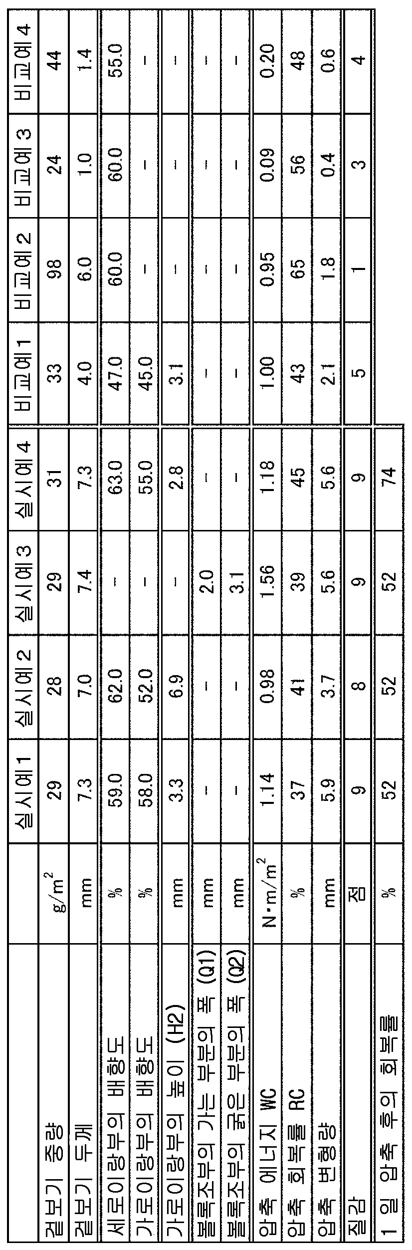
표 1 이 나타내는 바와 같이, 비교예 1 은 실시예 1 ∼ 4 와 동일하게 요철을 갖고 있었지만, 섬유 배향이 동일한 방향이고, 압축 변형량은, 세로이랑부의 섬유의 배향 방향과 가로이랑부의 섬유의 배향 방향이 상이한 실시예 1 ∼ 4 의 쪽이 우수하였다. 비교예 2 는 실시예와 동등 이상의 겉보기 두께를 갖고 있었지만, 형상이 플랫하기 때문에, 압축 변형량은 실시예 1 ∼ 4 의 쪽이 우수하였다. 비교예 3 은 실시예와 동일 정도로 섬유량이 적지만, 실시예 1 ∼ 4 의 쪽이 두께를 갖고 있었다. 또, 압축 변형량은 실시예 1 ∼ 4 의 쪽이 컸다. 비교예 4 는 실시예와 동일하게 요철을 갖고 있었지만, 배향 방향이 동일하기 때문에, 압축 변형량이 실시예 1 ∼ 4 의 쪽이 컸다.As Table 1 shows, the comparative example 1 had unevenness | corrugation similarly to Examples 1-4, but fiber orientation is the same direction, and the amount of compression deformation is the orientation direction of the fiber of a longitudinal groove, and the orientation direction of the fiber of a horizontal groove. This different Example 1-4 was excellent. Comparative Example 2 had an apparent thickness equal to or greater than that of Example, but because the shape was flat, the compressive deformation amount was better in Examples 1 to 4. Comparative Example 3 had a small amount of fiber to the same extent as in Example, but Examples 1 to 4 had a thickness. In addition, the compressive deformation amount was larger in Examples 1 to 4. Although the comparative example 4 had unevenness similarly to the Example, since the orientation direction was the same, the amount of compression deformation of Examples 1-4 was larger.
이상과 같이 실시예 1 ∼ 4 에서는 세로이랑부와 가로이랑부에 있어서 배향이 상이하기 때문에 압축 변형량이 많고, 적당한 탄력성과 쿠션감으로부터, 질감이 좋은 것으로 느껴졌다. 또, 액 확산도 적은 것이 확인되었다.As mentioned above, in Examples 1-4, since the orientation differs in a vertical part and a horizontal part, the amount of compression deformation was large, and it felt that a texture was good from moderate elasticity and a feeling of cushion. It was also confirmed that the liquid diffusion was small.
또한, 실시예 1 ∼ 4 중에서도, 초 수지인 PE (유리 전이 성분의 온도가 심 수지인 PET 보다 낮다) 의 질량비를 작게 한 실시예 4 는, 1 일 압축 후의 회복성이 우수하고, 팩 등으로 부직포를 짓누른 다음에도 두께의 회복성이 높은 것을 알 수 있었다.Moreover, also in Examples 1-4, Example 4 which made the mass ratio of PE which is super resin (the temperature of a glass transition component lower than PET which is a core resin) small is excellent in the recovery after 1-day compression, and a pack etc. Even after pressing the nonwoven fabric, it was found that the recovery of thickness was high.
본 발명을 그 실시형태 및 실시예와 함께 설명했지만, 우리는 특별히 지정하지 않는 한 우리의 발명을 설명의 어느 세부 (細部) 에 있어서도 한정하고자 하는 것이 아니라, 첨부한 청구의 범위에 나타낸 발명의 정신과 범위에 반하는 일 없이 폭넓게 해석되어야 한다고 생각한다.Although the present invention has been described with its embodiments and examples, we do not intend to limit our invention in any detail of the description unless otherwise specified, and the spirit of the invention as set forth in the appended claims. I think it should be interpreted broadly without contradicting its scope.
본원은, 2017년 8월 31일에 일본에서 특허 출원된 일본 특허출원 2017-168002 에 기초하는 우선권을 주장하는 것이고, 이것들은 여기에 참조하여 그 내용을 본 명세서의 기재된 일부로서 도입한다.This application claims the priority based on Japanese Patent Application No. 2017-168002 for which it applied in Japan on August 31, 2017, These introduce the content as a part of description of this specification with reference to here.
10, 10A, 10B, 10C : 부직포
11: 세로이랑부
11T : 정부 영역
11W : 벽부
12 : 내부 공간
14 : 골부
21 : 가로이랑부
21T : 정부 영역
21W : 벽부
22 : 내부 공간
31 : 볼록조부
31T : 정부 영역
31W : 벽부
32 : 내부 공간
34 : 볼록부
35 : 오목부
36 : 오목조부
37 : 가는 부분
38 : 굵은 부분
H1 : 세로이랑부의 높이
H2 : 가로이랑부의 높이
h1 : 볼록부의 높이
h2 : 오목부의 높이
S : 평면
Q1 : 가는 부분의 폭
Q2 : 굵은 부분의 폭
Z1 : 일방의 면측
Z2 : 반대면측10, 10A, 10B, 10C: Nonwoven
11: portrait
11T: Government Area
11W: wall
12: interior space
14 bone
21: horizontal gyrus
21T: Government Area
21W: Wall
22: interior space
31: convex grandfather
31T: Government Area
31W: wall
32: interior space
34 convex part
35 recess
36: recessed part
37: thin section
38: thick part
H1: height of vertical ridge
H2: Height of the ridge
h1: height of convexity
h2: height of recess
S: flat
Q1: width of thin section
Q2: width of thick part
Z1: One side
Z2: Opposite side
Claims (31)
상기 일방의 면측에,
상기 부직포의 두께 방향에 있어서 그 일방의 면측에 돌출하는 복수의 세로이랑부가, 평면에서 본 일방의 면측의 일방향으로 연장되고, 또한 그 일방의 면측의 일방향과는 상이한 평면에서 본 일방의 면측의 타방향으로 이간하여 나란히 배치되고,
상기 일방의 면측의 타방향으로 연장되는 가로이랑부가 상기 세로이랑부를 연결하여 배치되어 있고,
상기 세로이랑부를 구성하는 섬유의 배향 방향과 상기 가로이랑부를 구성하는 섬유의 배향 방향이 상이한, 부직포.As a nonwoven fabric which has one surface among the front and back surfaces of a nonwoven fabric, and the opposite surface of the opposite side with respect to the one surface,
On the one side of the said,
In the thickness direction of the said nonwoven fabric, the some longitudinal groove part which protrudes to the one surface side extends in one direction of the one surface side seen from the plane, and the other surface side of the one surface side seen from the plane different from the one direction of the one surface side. Placed side by side apart in the direction,
The horizontal grooves extending in the other direction on the one side of the surface are arranged to connect the vertical grooves,
The nonwoven fabric of which the orientation direction of the fiber which comprises the said vertical groove part is different from the orientation direction of the fiber which comprises the said horizontal groove part.
상기 반대면측에,
평면에서 본 반대면측의 일방향으로 연장되고, 또한 그 반대면측의 일방향과는 상이한 반대면측의 타방향으로 이간하여 늘어선 복수의 볼록조부를 갖고,
복수의 그 볼록조부에 끼인 오목조부를 갖고, 그 오목조부가 상기 반대면측의 일방향으로 연장되어 있는, 부직포.The method of claim 1,
On the opposite side,
It has a plurality of convex jaws extending in one direction on the opposite surface side seen from the plane, and spaced apart in the other direction on the opposite surface side different from one direction on the opposite surface side,
The nonwoven fabric which has a recessed tank part pinched by the some convex tank part, and the recessed tank part is extended in the one direction of the said opposing surface side.
상기 반대면측에,
평면에서 본 반대면측의 일방향으로 연장되고, 또한 그 반대면측의 일방향과는 상이한 반대면측의 타방향으로 이간하여 늘어선 복수의 볼록조부를 갖고,
복수의 그 볼록조부에 끼인 오목조부를 갖고, 그 오목조부가 상기 반대면측의 일방향으로 연장되어 있고,
상기 볼록조부는, 복수의 볼록부가 능선상으로 이어져 있고, 평면에서 보았을 때에 폭이 가는 부분과 굵은 부분이 번갈아 연결되어 배치되어 있는, 부직포.As a nonwoven fabric which has one surface among the front and back surfaces of a nonwoven fabric, and the opposite surface of the opposite side with respect to the one surface,
On the opposite side,
It has a plurality of convex jaws extending in one direction on the opposite surface side seen from the plane, and spaced apart in the other direction on the opposite surface side different from one direction on the opposite surface side,
It has a recessed tank part pinched by the some convex tank part, The recessed tank part is extended in the one direction of the said opposite surface side,
The said convex rough part is a nonwoven fabric in which the some convex part continues in ridgeline, and the narrow part and the thick part are arrange | positioned alternately and arrange | positioned when it sees in plan view.
상기 일방의 면측에,
상기 부직포의 두께 방향에 있어서 그 일방의 면측에 돌출하는 복수의 세로이랑부가, 평면에서 본 일방의 면측의 일방향으로 연장되고, 또한 그 일방의 면측의 일방향과는 상이한 평면에서 본 일방의 면측의 타방향으로 이간하여 나란히 배치되어 있는, 부직포.The method of claim 3, wherein
On the one side of the said,
In the thickness direction of the said nonwoven fabric, the some longitudinal groove part which protrudes to the one surface side extends in one direction of the one surface side seen from the plane, and the other surface side of the one surface side seen from the plane different from the one direction of the one surface side. A nonwoven fabric disposed side by side in a direction.
복수의 상기 가로이랑부가 상기 일방의 면측의 일방향으로 이간하여 나란히 배치되어 있는, 부직포.The method according to claim 1 or 2,
The nonwoven fabric in which a plurality of said horizontal grooves are arrange | positioned side by side in the one direction of the said one surface side.
상기 세로이랑부를 구성하는 섬유의 배향 방향 및 상기 가로이랑부를 구성하는 섬유의 배향 방향이, 각각의 이랑부가 연장되는 방향을 향하고 있는, 부직포.The method according to claim 1 or 2,
The nonwoven fabric of which the orientation direction of the fiber which comprises the said vertical groove part, and the orientation direction of the fiber which comprises the said horizontal groove part face the direction in which each groove part extends.
상기 세로이랑부의 높이와 상기 가로이랑부의 높이가 상이한, 부직포.The method according to claim 1 or 2,
The height of the said vertical furrow part and the height of the said horizontal furrow part are different from a nonwoven fabric.
상기 세로이랑부의 높이가 상기 가로이랑부의 높이보다 높은, 부직포.The method according to claim 1 or 2,
The nonwoven fabric of which the height of the said vertical furrow part is higher than the height of the said horizontal furrow part.
상기 가로이랑부가 상기 부직포의 두께 방향으로 만곡하고 있는, 부직포.The method according to claim 1 or 2,
The nonwoven fabric in which the said ribs are curved in the thickness direction of the said nonwoven fabric.
상기 반대면측으로부터 평면에서 본 상기 볼록조부의 폭 방향의 윤곽을 구성하는 2 개의 선 각각이 복수의 호 (弧) 를 갖는 곡선인, 부직포.The method according to any one of claims 2 to 4,
A nonwoven fabric, wherein each of the two lines constituting the contour in the width direction of the convex portion viewed in plan from the opposite surface side is a curve having a plurality of arcs.
상기 볼록조부의 측부에 보풀을 갖는, 부직포.The method according to any one of claims 2 to 4,
A nonwoven fabric having a fluff on the side of the convex jaw portion.
상기 일방의 면측의 일방향과 상기 반대면측의 일방향이 일치하고 있는, 부직포.The method according to any one of claims 2 to 4,
The nonwoven fabric of which the one direction of the said one surface side and the one direction of the said opposite surface side correspond.
Applications Claiming Priority (3)
| Application Number | Priority Date | Filing Date | Title |
|---|---|---|---|
| JPJP-P-2017-168002 | 2017-08-31 | ||
| JP2017168002 | 2017-08-31 | ||
| PCT/JP2018/026730 WO2019044219A1 (en) | 2017-08-31 | 2018-07-17 | Nonwoven fabric |
Publications (2)
| Publication Number | Publication Date |
|---|---|
| KR20190122862A KR20190122862A (en) | 2019-10-30 |
| KR102075342B1 true KR102075342B1 (en) | 2020-02-10 |
Family
ID=65526290
Family Applications (1)
| Application Number | Title | Priority Date | Filing Date |
|---|---|---|---|
| KR1020197030266A Expired - Fee Related KR102075342B1 (en) | 2017-08-31 | 2018-07-17 | Non-woven |
Country Status (10)
| Country | Link |
|---|---|
| US (1) | US11168420B2 (en) |
| JP (1) | JP6561182B2 (en) |
| KR (1) | KR102075342B1 (en) |
| CN (1) | CN110799688B (en) |
| DE (1) | DE112018002956T5 (en) |
| GB (1) | GB2577821B (en) |
| MY (1) | MY193699A (en) |
| RU (1) | RU2731233C1 (en) |
| TW (2) | TW202225512A (en) |
| WO (1) | WO2019044219A1 (en) |
Families Citing this family (43)
| Publication number | Priority date | Publication date | Assignee | Title |
|---|---|---|---|---|
| US11376152B2 (en) | 2014-03-19 | 2022-07-05 | Purewick Corporation | Apparatus and methods for receiving discharged urine |
| US10226376B2 (en) | 2014-03-19 | 2019-03-12 | Purewick Corporation | Apparatus and methods for receiving discharged urine |
| US10952889B2 (en) | 2016-06-02 | 2021-03-23 | Purewick Corporation | Using wicking material to collect liquid for transport |
| US10390989B2 (en) | 2014-03-19 | 2019-08-27 | Purewick Corporation | Apparatus and methods for receiving discharged urine |
| WO2018144463A1 (en) | 2017-01-31 | 2018-08-09 | Purewick Corporation | Apparatus and methods for receiving discharged urine |
| CA3098571C (en) | 2018-05-01 | 2023-09-26 | Purewick Corporation | Fluid collection devices, systems, and methods |
| JP7072084B2 (en) | 2018-05-01 | 2022-05-19 | ピュアウィック コーポレイション | Fluid collectors, related systems, and related methods |
| JP7093852B2 (en) | 2018-05-01 | 2022-06-30 | ピュアウィック コーポレイション | Fluid collector and how to use it |
| USD907932S1 (en) * | 2018-12-14 | 2021-01-19 | Berry Global, Inc. | Nonwoven fabric |
| WO2020184595A2 (en) | 2019-03-11 | 2020-09-17 | Canon Kabushiki Kaisha | Image forming apparatus |
| WO2020256865A1 (en) | 2019-06-21 | 2020-12-24 | Purewick Corporation | Fluid collection devices including a base securement area, and related systems and methods |
| WO2021016026A1 (en) | 2019-07-19 | 2021-01-28 | Purewick Corporation | Fluid collection devices including at least one shape memory material |
| ES2980872T3 (en) | 2019-10-28 | 2024-10-03 | Purewick Corp | Liquid collection assemblies that include a sample port |
| WO2021138414A1 (en) | 2020-01-03 | 2021-07-08 | Purewick Corporation | Urine collection devices having a relatively wide portion and an elongated portion and related methods |
| WO2021195384A1 (en) | 2020-03-26 | 2021-09-30 | Purewick Corporation | Multi-layered urine capture device and related methods |
| TWI883165B (en) * | 2020-04-09 | 2025-05-11 | 日商花王股份有限公司 | Nonwoven fabrics and absorbent articles |
| JP7389916B2 (en) | 2020-04-10 | 2023-11-30 | ピュアウィック コーポレイション | Fluid collection assembly including one or more leak protection features |
| WO2021211801A1 (en) | 2020-04-17 | 2021-10-21 | Purewick Corporation | Fluid collection assemblies including a fluid impermeable barrier having a sump and a base |
| WO2021211599A1 (en) | 2020-04-17 | 2021-10-21 | Purewick Corporation | Female external catheter devices having a urethral cup, and related systems and methods |
| US12465514B2 (en) | 2020-04-17 | 2025-11-11 | Purewick Corporation | Fluid collection devices, systems, and methods securing a protruding portion in position for use |
| US12491104B2 (en) | 2020-04-20 | 2025-12-09 | Purewick Corporation | Fluid collection devices adjustable between a vacuum-based orientation and a gravity-based orientation, and related systems and methods |
| US12440371B2 (en) | 2020-08-06 | 2025-10-14 | Purewick Corporation | Fluid collection system including a garment and a fluid collection device |
| US12350187B2 (en) | 2020-08-11 | 2025-07-08 | Purewick Corporation | Fluid collection assemblies defining waist and leg openings |
| EP4210643A1 (en) | 2020-09-09 | 2023-07-19 | Purewick Corporation | Fluid collection devices, systems, and methods |
| US12156792B2 (en) | 2020-09-10 | 2024-12-03 | Purewick Corporation | Fluid collection assemblies including at least one inflation device |
| US12042423B2 (en) | 2020-10-07 | 2024-07-23 | Purewick Corporation | Fluid collection systems including at least one tensioning element |
| US12208031B2 (en) | 2020-10-21 | 2025-01-28 | Purewick Corporation | Adapters for fluid collection devices |
| US12257174B2 (en) | 2020-10-21 | 2025-03-25 | Purewick Corporation | Fluid collection assemblies including at least one of a protrusion or at least one expandable material |
| US12440370B2 (en) | 2020-10-21 | 2025-10-14 | Purewick Corporation | Apparatus with compressible casing for receiving discharged urine |
| US12070432B2 (en) | 2020-11-11 | 2024-08-27 | Purewick Corporation | Urine collection system including a flow meter and related methods |
| US12245967B2 (en) | 2020-11-18 | 2025-03-11 | Purewick Corporation | Fluid collection assemblies including an adjustable spine |
| US12268627B2 (en) | 2021-01-06 | 2025-04-08 | Purewick Corporation | Fluid collection assemblies including at least one securement body |
| US12478499B2 (en) | 2021-01-07 | 2025-11-25 | Purewick Corporation | Wheelchair securable urine collection systems and related methods |
| ES2975761T3 (en) | 2021-01-19 | 2024-07-15 | Purewick Corp | Variable adjustment liquid collection device |
| US12178735B2 (en) | 2021-02-09 | 2024-12-31 | Purewick Corporation | Noise reduction for a urine suction system |
| CN116615162A (en) | 2021-02-26 | 2023-08-18 | 普奥维克有限公司 | Fluid collection device with reservoir between nozzle and barrier and related systems and methods |
| US12458525B2 (en) | 2021-03-10 | 2025-11-04 | Purewick Corporation | Acoustic silencer for a urine suction system |
| US12029677B2 (en) | 2021-04-06 | 2024-07-09 | Purewick Corporation | Fluid collection devices having a collection bag, and related systems and methods |
| US12233003B2 (en) | 2021-04-29 | 2025-02-25 | Purewick Corporation | Fluid collection assemblies including at least one length adjusting feature |
| US12251333B2 (en) | 2021-05-21 | 2025-03-18 | Purewick Corporation | Fluid collection assemblies including at least one inflation device and methods and systems of using the same |
| US12324767B2 (en) | 2021-05-24 | 2025-06-10 | Purewick Corporation | Fluid collection assembly including a customizable external support and related methods |
| US12150885B2 (en) | 2021-05-26 | 2024-11-26 | Purewick Corporation | Fluid collection system including a cleaning system and methods |
| JP2023166229A (en) * | 2022-05-09 | 2023-11-21 | 花王株式会社 | non-woven fabric |
Citations (2)
| Publication number | Priority date | Publication date | Assignee | Title |
|---|---|---|---|---|
| JP2006520324A (en) | 2002-12-20 | 2006-09-07 | ザ プロクター アンド ギャンブル カンパニー | Cloth-like personal care products |
| JP2016220985A (en) | 2015-05-29 | 2016-12-28 | ユニ・チャーム株式会社 | Method of producing shaped non-woven fabric for absorbent article |
Family Cites Families (24)
| Publication number | Priority date | Publication date | Assignee | Title |
|---|---|---|---|---|
| US4207367A (en) * | 1970-03-30 | 1980-06-10 | Scott Paper Company | Nonwoven fabric |
| US3969561A (en) * | 1974-09-17 | 1976-07-13 | The Kendall Company | Biaxially oriented nonwoven fabrics and method of making same |
| US6765125B2 (en) * | 1999-02-12 | 2004-07-20 | Kimberly-Clark Worldwide, Inc. | Distribution—Retention material for personal care products |
| JP3748743B2 (en) | 1999-10-04 | 2006-02-22 | ユニ・チャーム株式会社 | Absorbent article and manufacturing method thereof |
| JP2002023764A (en) * | 2000-07-05 | 2002-01-25 | Toray Ind Inc | Acoustic material |
| JP4414084B2 (en) | 2000-11-13 | 2010-02-10 | 新日本石油化学株式会社 | Composite nonwoven fabric and method for producing the same |
| RU2205911C2 (en) * | 2000-12-19 | 2003-06-10 | Хьюматро Корпорейшн | Flexible structure comprising starch filaments |
| MXPA05005755A (en) | 2002-12-20 | 2005-08-16 | Procter & Gamble | Tufted fibrous web. |
| TWI358283B (en) | 2004-08-20 | 2012-02-21 | Kao Corp | Process of producing an absorbent article |
| US8221372B2 (en) * | 2005-06-15 | 2012-07-17 | Daio Paper Corporation | Disposable diaper having folded front-sided end flap portion |
| WO2008146594A1 (en) * | 2007-05-24 | 2008-12-04 | Kao Corporation | Surface sheet for absorptive article, method of producing the surface sheet, and absorptive article |
| JP5631035B2 (en) | 2010-03-29 | 2014-11-26 | ユニ・チャーム株式会社 | Nonwoven sheet |
| JP5538977B2 (en) * | 2010-03-29 | 2014-07-02 | ユニ・チャーム株式会社 | Non-woven sheet and method for producing the same |
| JP5729948B2 (en) * | 2010-08-31 | 2015-06-03 | ユニ・チャーム株式会社 | Nonwoven sheet, method for producing the same, and absorbent article |
| JP5764323B2 (en) * | 2010-12-24 | 2015-08-19 | 花王株式会社 | Non-woven fabric and absorbent article using the same |
| JP5961972B2 (en) | 2011-10-12 | 2016-08-03 | Jnc株式会社 | Elastic bulky nonwoven fabric and method for producing the same |
| CN202415959U (en) * | 2011-12-31 | 2012-09-05 | 金红叶纸业集团有限公司 | Embossing equipment, composite non-woven fabric absorbing body and production equipment of composite non-woven fabric absorbing body |
| JP5998000B2 (en) * | 2012-09-30 | 2016-09-28 | ユニ・チャーム株式会社 | Nonwoven fabric and absorbent article |
| JP6209331B2 (en) * | 2012-12-03 | 2017-10-04 | 花王株式会社 | Method for producing uneven sheet and nonwoven fabric |
| JP6190260B2 (en) * | 2013-12-09 | 2017-08-30 | 花王株式会社 | Nonwoven manufacturing method |
| JP5829327B1 (en) | 2014-12-26 | 2015-12-09 | ユニ・チャーム株式会社 | Nonwoven fabric for absorbent articles |
| WO2016104768A1 (en) * | 2014-12-26 | 2016-06-30 | ユニ・チャーム株式会社 | Method for producing shaped non-woven fabric for absorbent article |
| JP6038228B1 (en) | 2015-05-22 | 2016-12-07 | ユニ・チャーム株式会社 | Absorbent articles |
| EP3328336B1 (en) * | 2015-07-31 | 2021-10-13 | The Procter & Gamble Company | Shaped nonwoven |
-
2018
- 2018-07-17 KR KR1020197030266A patent/KR102075342B1/en not_active Expired - Fee Related
- 2018-07-17 TW TW111109533A patent/TW202225512A/en unknown
- 2018-07-17 TW TW107124565A patent/TWI766070B/en not_active IP Right Cessation
- 2018-07-17 WO PCT/JP2018/026730 patent/WO2019044219A1/en not_active Ceased
- 2018-07-17 RU RU2019143700A patent/RU2731233C1/en active
- 2018-07-17 CN CN201880042089.4A patent/CN110799688B/en active Active
- 2018-07-17 MY MYPI2019006955A patent/MY193699A/en unknown
- 2018-07-17 GB GB1917378.0A patent/GB2577821B/en active Active
- 2018-07-17 DE DE112018002956.5T patent/DE112018002956T5/en not_active Withdrawn
- 2018-07-17 US US16/609,371 patent/US11168420B2/en active Active
- 2018-07-17 JP JP2018134297A patent/JP6561182B2/en active Active
Patent Citations (2)
| Publication number | Priority date | Publication date | Assignee | Title |
|---|---|---|---|---|
| JP2006520324A (en) | 2002-12-20 | 2006-09-07 | ザ プロクター アンド ギャンブル カンパニー | Cloth-like personal care products |
| JP2016220985A (en) | 2015-05-29 | 2016-12-28 | ユニ・チャーム株式会社 | Method of producing shaped non-woven fabric for absorbent article |
Also Published As
| Publication number | Publication date |
|---|---|
| US11168420B2 (en) | 2021-11-09 |
| MY193699A (en) | 2022-10-25 |
| WO2019044219A1 (en) | 2019-03-07 |
| KR20190122862A (en) | 2019-10-30 |
| JP2019044320A (en) | 2019-03-22 |
| GB2577821A (en) | 2020-04-08 |
| JP6561182B2 (en) | 2019-08-14 |
| GB201917378D0 (en) | 2020-01-15 |
| GB2577821B (en) | 2021-01-06 |
| TWI766070B (en) | 2022-06-01 |
| CN110799688A (en) | 2020-02-14 |
| RU2731233C1 (en) | 2020-08-31 |
| CN110799688B (en) | 2022-03-11 |
| US20200056313A1 (en) | 2020-02-20 |
| DE112018002956T5 (en) | 2020-04-02 |
| TW201923188A (en) | 2019-06-16 |
| TW202225512A (en) | 2022-07-01 |
Similar Documents
| Publication | Publication Date | Title |
|---|---|---|
| KR102075342B1 (en) | Non-woven | |
| KR102100102B1 (en) | Non-woven | |
| RU2736266C1 (en) | Non-woven material | |
| KR101515518B1 (en) | Shaped sheet and absorbent article utilizing the same | |
| JP3408078B2 (en) | Absorbent articles | |
| KR101100572B1 (en) | Interlabial pad | |
| RU2617985C2 (en) | Non-woven material | |
| KR20120067353A (en) | Disposable wearing article | |
| US7270652B2 (en) | Interlabial pad | |
| JP7504959B2 (en) | Nonwoven fabric manufacturing method | |
| JP2015112339A (en) | Top sheet of absorbent article and absorbent article | |
| JP3862653B2 (en) | Absorbent article and liquid permeable sheet therefor | |
| KR20040000492A (en) | Interlabial pad | |
| EP1946730A1 (en) | Absorbent article | |
| JP3225511U (en) | Nonwoven fabric for absorbent article and absorbent article using the same | |
| JP2022174632A (en) | Nonwoven fabric and absorbent article containing this as a constituent member | |
| JP3249760U (en) | Nonwoven fabric for absorbent articles | |
| JP2025018041A (en) | Nonwoven | |
| JP2024132465A (en) | Nonwoven fabric sheet for absorbent articles | |
| JP2024166579A (en) | Absorbent articles | |
| KR20080061283A (en) | Surface sheet for absorbent article and its manufacturing method | |
| JP2024046545A (en) | Nonwoven fabric for absorbent articles | |
| JP2023054943A (en) | Surface sheet for absorbent article |
Legal Events
| Date | Code | Title | Description |
|---|---|---|---|
| A201 | Request for examination | ||
| A302 | Request for accelerated examination | ||
| E13-X000 | Pre-grant limitation requested |
St.27 status event code: A-2-3-E10-E13-lim-X000 |
|
| P11-X000 | Amendment of application requested |
St.27 status event code: A-2-2-P10-P11-nap-X000 |
|
| P13-X000 | Application amended |
St.27 status event code: A-2-2-P10-P13-nap-X000 |
|
| PA0105 | International application |
St.27 status event code: A-0-1-A10-A15-nap-PA0105 |
|
| PA0201 | Request for examination |
St.27 status event code: A-1-2-D10-D11-exm-PA0201 |
|
| PA0302 | Request for accelerated examination |
St.27 status event code: A-1-2-D10-D17-exm-PA0302 St.27 status event code: A-1-2-D10-D16-exm-PA0302 |
|
| PG1501 | Laying open of application |
St.27 status event code: A-1-1-Q10-Q12-nap-PG1501 |
|
| E701 | Decision to grant or registration of patent right | ||
| PE0701 | Decision of registration |
St.27 status event code: A-1-2-D10-D22-exm-PE0701 |
|
| GRNT | Written decision to grant | ||
| PR0701 | Registration of establishment |
St.27 status event code: A-2-4-F10-F11-exm-PR0701 |
|
| PR1002 | Payment of registration fee |
St.27 status event code: A-2-2-U10-U12-oth-PR1002 Fee payment year number: 1 |
|
| PG1601 | Publication of registration |
St.27 status event code: A-4-4-Q10-Q13-nap-PG1601 |
|
| PC1903 | Unpaid annual fee |
St.27 status event code: A-4-4-U10-U13-oth-PC1903 Not in force date: 20230205 Payment event data comment text: Termination Category : DEFAULT_OF_REGISTRATION_FEE |
|
| PC1903 | Unpaid annual fee |
St.27 status event code: N-4-6-H10-H13-oth-PC1903 Ip right cessation event data comment text: Termination Category : DEFAULT_OF_REGISTRATION_FEE Not in force date: 20230205 |