KR102040712B1 - Wireless power transmission system, method and apparatus for communication channel allocation and power transmission in wireless power transmission system - Google Patents
Wireless power transmission system, method and apparatus for communication channel allocation and power transmission in wireless power transmission system Download PDFInfo
- Publication number
- KR102040712B1 KR102040712B1 KR1020120058369A KR20120058369A KR102040712B1 KR 102040712 B1 KR102040712 B1 KR 102040712B1 KR 1020120058369 A KR1020120058369 A KR 1020120058369A KR 20120058369 A KR20120058369 A KR 20120058369A KR 102040712 B1 KR102040712 B1 KR 102040712B1
- Authority
- KR
- South Korea
- Prior art keywords
- channel
- communication
- communication channel
- target device
- source device
- Prior art date
- Legal status (The legal status is an assumption and is not a legal conclusion. Google has not performed a legal analysis and makes no representation as to the accuracy of the status listed.)
- Active
Links
Images


Classifications
-
- H—ELECTRICITY
- H02—GENERATION; CONVERSION OR DISTRIBUTION OF ELECTRIC POWER
- H02J—CIRCUIT ARRANGEMENTS OR SYSTEMS FOR SUPPLYING OR DISTRIBUTING ELECTRIC POWER; SYSTEMS FOR STORING ELECTRIC ENERGY
- H02J50/00—Circuit arrangements or systems for wireless supply or distribution of electric power
- H02J50/20—Circuit arrangements or systems for wireless supply or distribution of electric power using microwaves or radio frequency waves
-
- B—PERFORMING OPERATIONS; TRANSPORTING
- B60—VEHICLES IN GENERAL
- B60L—PROPULSION OF ELECTRICALLY-PROPELLED VEHICLES; SUPPLYING ELECTRIC POWER FOR AUXILIARY EQUIPMENT OF ELECTRICALLY-PROPELLED VEHICLES; ELECTRODYNAMIC BRAKE SYSTEMS FOR VEHICLES IN GENERAL; MAGNETIC SUSPENSION OR LEVITATION FOR VEHICLES; MONITORING OPERATING VARIABLES OF ELECTRICALLY-PROPELLED VEHICLES; ELECTRIC SAFETY DEVICES FOR ELECTRICALLY-PROPELLED VEHICLES
- B60L53/00—Methods of charging batteries, specially adapted for electric vehicles; Charging stations or on-board charging equipment therefor; Exchange of energy storage elements in electric vehicles
- B60L53/10—Methods of charging batteries, specially adapted for electric vehicles; Charging stations or on-board charging equipment therefor; Exchange of energy storage elements in electric vehicles characterised by the energy transfer between the charging station and the vehicle
- B60L53/12—Inductive energy transfer
- B60L53/126—Methods for pairing a vehicle and a charging station, e.g. establishing a one-to-one relation between a wireless power transmitter and a wireless power receiver
-
- B—PERFORMING OPERATIONS; TRANSPORTING
- B60—VEHICLES IN GENERAL
- B60L—PROPULSION OF ELECTRICALLY-PROPELLED VEHICLES; SUPPLYING ELECTRIC POWER FOR AUXILIARY EQUIPMENT OF ELECTRICALLY-PROPELLED VEHICLES; ELECTRODYNAMIC BRAKE SYSTEMS FOR VEHICLES IN GENERAL; MAGNETIC SUSPENSION OR LEVITATION FOR VEHICLES; MONITORING OPERATING VARIABLES OF ELECTRICALLY-PROPELLED VEHICLES; ELECTRIC SAFETY DEVICES FOR ELECTRICALLY-PROPELLED VEHICLES
- B60L53/00—Methods of charging batteries, specially adapted for electric vehicles; Charging stations or on-board charging equipment therefor; Exchange of energy storage elements in electric vehicles
- B60L53/30—Constructional details of charging stations
- B60L53/35—Means for automatic or assisted adjustment of the relative position of charging devices and vehicles
- B60L53/36—Means for automatic or assisted adjustment of the relative position of charging devices and vehicles by positioning the vehicle
-
- H—ELECTRICITY
- H02—GENERATION; CONVERSION OR DISTRIBUTION OF ELECTRIC POWER
- H02J—CIRCUIT ARRANGEMENTS OR SYSTEMS FOR SUPPLYING OR DISTRIBUTING ELECTRIC POWER; SYSTEMS FOR STORING ELECTRIC ENERGY
- H02J50/00—Circuit arrangements or systems for wireless supply or distribution of electric power
- H02J50/10—Circuit arrangements or systems for wireless supply or distribution of electric power using inductive coupling
- H02J50/12—Circuit arrangements or systems for wireless supply or distribution of electric power using inductive coupling of the resonant type
-
- H—ELECTRICITY
- H02—GENERATION; CONVERSION OR DISTRIBUTION OF ELECTRIC POWER
- H02J—CIRCUIT ARRANGEMENTS OR SYSTEMS FOR SUPPLYING OR DISTRIBUTING ELECTRIC POWER; SYSTEMS FOR STORING ELECTRIC ENERGY
- H02J50/00—Circuit arrangements or systems for wireless supply or distribution of electric power
- H02J50/40—Circuit arrangements or systems for wireless supply or distribution of electric power using two or more transmitting or receiving devices
-
- H—ELECTRICITY
- H02—GENERATION; CONVERSION OR DISTRIBUTION OF ELECTRIC POWER
- H02J—CIRCUIT ARRANGEMENTS OR SYSTEMS FOR SUPPLYING OR DISTRIBUTING ELECTRIC POWER; SYSTEMS FOR STORING ELECTRIC ENERGY
- H02J50/00—Circuit arrangements or systems for wireless supply or distribution of electric power
- H02J50/70—Circuit arrangements or systems for wireless supply or distribution of electric power involving the reduction of electric, magnetic or electromagnetic leakage fields
-
- H—ELECTRICITY
- H02—GENERATION; CONVERSION OR DISTRIBUTION OF ELECTRIC POWER
- H02J—CIRCUIT ARRANGEMENTS OR SYSTEMS FOR SUPPLYING OR DISTRIBUTING ELECTRIC POWER; SYSTEMS FOR STORING ELECTRIC ENERGY
- H02J50/00—Circuit arrangements or systems for wireless supply or distribution of electric power
- H02J50/80—Circuit arrangements or systems for wireless supply or distribution of electric power involving the exchange of data, concerning supply or distribution of electric power, between transmitting devices and receiving devices
-
- H—ELECTRICITY
- H02—GENERATION; CONVERSION OR DISTRIBUTION OF ELECTRIC POWER
- H02J—CIRCUIT ARRANGEMENTS OR SYSTEMS FOR SUPPLYING OR DISTRIBUTING ELECTRIC POWER; SYSTEMS FOR STORING ELECTRIC ENERGY
- H02J50/00—Circuit arrangements or systems for wireless supply or distribution of electric power
- H02J50/90—Circuit arrangements or systems for wireless supply or distribution of electric power involving detection or optimisation of position, e.g. alignment
-
- H02J7/42—
-
- H—ELECTRICITY
- H04—ELECTRIC COMMUNICATION TECHNIQUE
- H04B—TRANSMISSION
- H04B17/00—Monitoring; Testing
- H04B17/30—Monitoring; Testing of propagation channels
- H04B17/309—Measuring or estimating channel quality parameters
- H04B17/318—Received signal strength
-
- H—ELECTRICITY
- H04—ELECTRIC COMMUNICATION TECHNIQUE
- H04B—TRANSMISSION
- H04B5/00—Near-field transmission systems, e.g. inductive or capacitive transmission systems
- H04B5/20—Near-field transmission systems, e.g. inductive or capacitive transmission systems characterised by the transmission technique; characterised by the transmission medium
- H04B5/24—Inductive coupling
- H04B5/26—Inductive coupling using coils
- H04B5/266—One coil at each side, e.g. with primary and secondary coils
-
- H—ELECTRICITY
- H04—ELECTRIC COMMUNICATION TECHNIQUE
- H04B—TRANSMISSION
- H04B5/00—Near-field transmission systems, e.g. inductive or capacitive transmission systems
- H04B5/40—Near-field transmission systems, e.g. inductive or capacitive transmission systems characterised by components specially adapted for near-field transmission
- H04B5/48—Transceivers
-
- H—ELECTRICITY
- H04—ELECTRIC COMMUNICATION TECHNIQUE
- H04B—TRANSMISSION
- H04B5/00—Near-field transmission systems, e.g. inductive or capacitive transmission systems
- H04B5/70—Near-field transmission systems, e.g. inductive or capacitive transmission systems specially adapted for specific purposes
- H04B5/79—Near-field transmission systems, e.g. inductive or capacitive transmission systems specially adapted for specific purposes for data transfer in combination with power transfer
-
- B—PERFORMING OPERATIONS; TRANSPORTING
- B60—VEHICLES IN GENERAL
- B60L—PROPULSION OF ELECTRICALLY-PROPELLED VEHICLES; SUPPLYING ELECTRIC POWER FOR AUXILIARY EQUIPMENT OF ELECTRICALLY-PROPELLED VEHICLES; ELECTRODYNAMIC BRAKE SYSTEMS FOR VEHICLES IN GENERAL; MAGNETIC SUSPENSION OR LEVITATION FOR VEHICLES; MONITORING OPERATING VARIABLES OF ELECTRICALLY-PROPELLED VEHICLES; ELECTRIC SAFETY DEVICES FOR ELECTRICALLY-PROPELLED VEHICLES
- B60L2210/00—Converter types
- B60L2210/10—DC to DC converters
-
- B—PERFORMING OPERATIONS; TRANSPORTING
- B60—VEHICLES IN GENERAL
- B60L—PROPULSION OF ELECTRICALLY-PROPELLED VEHICLES; SUPPLYING ELECTRIC POWER FOR AUXILIARY EQUIPMENT OF ELECTRICALLY-PROPELLED VEHICLES; ELECTRODYNAMIC BRAKE SYSTEMS FOR VEHICLES IN GENERAL; MAGNETIC SUSPENSION OR LEVITATION FOR VEHICLES; MONITORING OPERATING VARIABLES OF ELECTRICALLY-PROPELLED VEHICLES; ELECTRIC SAFETY DEVICES FOR ELECTRICALLY-PROPELLED VEHICLES
- B60L2210/00—Converter types
- B60L2210/30—AC to DC converters
-
- B—PERFORMING OPERATIONS; TRANSPORTING
- B60—VEHICLES IN GENERAL
- B60L—PROPULSION OF ELECTRICALLY-PROPELLED VEHICLES; SUPPLYING ELECTRIC POWER FOR AUXILIARY EQUIPMENT OF ELECTRICALLY-PROPELLED VEHICLES; ELECTRODYNAMIC BRAKE SYSTEMS FOR VEHICLES IN GENERAL; MAGNETIC SUSPENSION OR LEVITATION FOR VEHICLES; MONITORING OPERATING VARIABLES OF ELECTRICALLY-PROPELLED VEHICLES; ELECTRIC SAFETY DEVICES FOR ELECTRICALLY-PROPELLED VEHICLES
- B60L2210/00—Converter types
- B60L2210/40—DC to AC converters
-
- B—PERFORMING OPERATIONS; TRANSPORTING
- B60—VEHICLES IN GENERAL
- B60L—PROPULSION OF ELECTRICALLY-PROPELLED VEHICLES; SUPPLYING ELECTRIC POWER FOR AUXILIARY EQUIPMENT OF ELECTRICALLY-PROPELLED VEHICLES; ELECTRODYNAMIC BRAKE SYSTEMS FOR VEHICLES IN GENERAL; MAGNETIC SUSPENSION OR LEVITATION FOR VEHICLES; MONITORING OPERATING VARIABLES OF ELECTRICALLY-PROPELLED VEHICLES; ELECTRIC SAFETY DEVICES FOR ELECTRICALLY-PROPELLED VEHICLES
- B60L2250/00—Driver interactions
- B60L2250/16—Driver interactions by display
-
- H—ELECTRICITY
- H02—GENERATION; CONVERSION OR DISTRIBUTION OF ELECTRIC POWER
- H02J—CIRCUIT ARRANGEMENTS OR SYSTEMS FOR SUPPLYING OR DISTRIBUTING ELECTRIC POWER; SYSTEMS FOR STORING ELECTRIC ENERGY
- H02J50/00—Circuit arrangements or systems for wireless supply or distribution of electric power
- H02J50/005—Mechanical details of housing or structure aiming to accommodate the power transfer means, e.g. mechanical integration of coils, antennas or transducers into emitting or receiving devices
-
- Y—GENERAL TAGGING OF NEW TECHNOLOGICAL DEVELOPMENTS; GENERAL TAGGING OF CROSS-SECTIONAL TECHNOLOGIES SPANNING OVER SEVERAL SECTIONS OF THE IPC; TECHNICAL SUBJECTS COVERED BY FORMER USPC CROSS-REFERENCE ART COLLECTIONS [XRACs] AND DIGESTS
- Y02—TECHNOLOGIES OR APPLICATIONS FOR MITIGATION OR ADAPTATION AGAINST CLIMATE CHANGE
- Y02T—CLIMATE CHANGE MITIGATION TECHNOLOGIES RELATED TO TRANSPORTATION
- Y02T10/00—Road transport of goods or passengers
- Y02T10/60—Other road transportation technologies with climate change mitigation effect
- Y02T10/70—Energy storage systems for electromobility, e.g. batteries
-
- Y—GENERAL TAGGING OF NEW TECHNOLOGICAL DEVELOPMENTS; GENERAL TAGGING OF CROSS-SECTIONAL TECHNOLOGIES SPANNING OVER SEVERAL SECTIONS OF THE IPC; TECHNICAL SUBJECTS COVERED BY FORMER USPC CROSS-REFERENCE ART COLLECTIONS [XRACs] AND DIGESTS
- Y02—TECHNOLOGIES OR APPLICATIONS FOR MITIGATION OR ADAPTATION AGAINST CLIMATE CHANGE
- Y02T—CLIMATE CHANGE MITIGATION TECHNOLOGIES RELATED TO TRANSPORTATION
- Y02T10/00—Road transport of goods or passengers
- Y02T10/60—Other road transportation technologies with climate change mitigation effect
- Y02T10/7072—Electromobility specific charging systems or methods for batteries, ultracapacitors, supercapacitors or double-layer capacitors
-
- Y—GENERAL TAGGING OF NEW TECHNOLOGICAL DEVELOPMENTS; GENERAL TAGGING OF CROSS-SECTIONAL TECHNOLOGIES SPANNING OVER SEVERAL SECTIONS OF THE IPC; TECHNICAL SUBJECTS COVERED BY FORMER USPC CROSS-REFERENCE ART COLLECTIONS [XRACs] AND DIGESTS
- Y02—TECHNOLOGIES OR APPLICATIONS FOR MITIGATION OR ADAPTATION AGAINST CLIMATE CHANGE
- Y02T—CLIMATE CHANGE MITIGATION TECHNOLOGIES RELATED TO TRANSPORTATION
- Y02T10/00—Road transport of goods or passengers
- Y02T10/60—Other road transportation technologies with climate change mitigation effect
- Y02T10/72—Electric energy management in electromobility
-
- Y—GENERAL TAGGING OF NEW TECHNOLOGICAL DEVELOPMENTS; GENERAL TAGGING OF CROSS-SECTIONAL TECHNOLOGIES SPANNING OVER SEVERAL SECTIONS OF THE IPC; TECHNICAL SUBJECTS COVERED BY FORMER USPC CROSS-REFERENCE ART COLLECTIONS [XRACs] AND DIGESTS
- Y02—TECHNOLOGIES OR APPLICATIONS FOR MITIGATION OR ADAPTATION AGAINST CLIMATE CHANGE
- Y02T—CLIMATE CHANGE MITIGATION TECHNOLOGIES RELATED TO TRANSPORTATION
- Y02T90/00—Enabling technologies or technologies with a potential or indirect contribution to GHG emissions mitigation
- Y02T90/10—Technologies relating to charging of electric vehicles
- Y02T90/12—Electric charging stations
-
- Y—GENERAL TAGGING OF NEW TECHNOLOGICAL DEVELOPMENTS; GENERAL TAGGING OF CROSS-SECTIONAL TECHNOLOGIES SPANNING OVER SEVERAL SECTIONS OF THE IPC; TECHNICAL SUBJECTS COVERED BY FORMER USPC CROSS-REFERENCE ART COLLECTIONS [XRACs] AND DIGESTS
- Y02—TECHNOLOGIES OR APPLICATIONS FOR MITIGATION OR ADAPTATION AGAINST CLIMATE CHANGE
- Y02T—CLIMATE CHANGE MITIGATION TECHNOLOGIES RELATED TO TRANSPORTATION
- Y02T90/00—Enabling technologies or technologies with a potential or indirect contribution to GHG emissions mitigation
- Y02T90/10—Technologies relating to charging of electric vehicles
- Y02T90/14—Plug-in electric vehicles
-
- Y—GENERAL TAGGING OF NEW TECHNOLOGICAL DEVELOPMENTS; GENERAL TAGGING OF CROSS-SECTIONAL TECHNOLOGIES SPANNING OVER SEVERAL SECTIONS OF THE IPC; TECHNICAL SUBJECTS COVERED BY FORMER USPC CROSS-REFERENCE ART COLLECTIONS [XRACs] AND DIGESTS
- Y02—TECHNOLOGIES OR APPLICATIONS FOR MITIGATION OR ADAPTATION AGAINST CLIMATE CHANGE
- Y02T—CLIMATE CHANGE MITIGATION TECHNOLOGIES RELATED TO TRANSPORTATION
- Y02T90/00—Enabling technologies or technologies with a potential or indirect contribution to GHG emissions mitigation
- Y02T90/10—Technologies relating to charging of electric vehicles
- Y02T90/16—Information or communication technologies improving the operation of electric vehicles
Landscapes
- Engineering & Computer Science (AREA)
- Computer Networks & Wireless Communication (AREA)
- Power Engineering (AREA)
- Signal Processing (AREA)
- Transportation (AREA)
- Mechanical Engineering (AREA)
- Physics & Mathematics (AREA)
- Electromagnetism (AREA)
- Quality & Reliability (AREA)
- Charge And Discharge Circuits For Batteries Or The Like (AREA)
Abstract
무선 전력 전송 시스템, 무선 전력 전송 시스템에서 통신 채널 할당 및 전력 전송 방법 및 그 장치가 개시된다.
소스 디바이스로부터 무선으로 전력을 수신하는 타겟 디바이스가 검출되면, 상기 타겟 디바이스와 통신을 수행하기 위한 제어용 통신 채널이 선택될 수 있다. 상기 선택된 제어용 통신 채널을 통해 채널 고정 명령어 및 상기 소스 디바이스의 식별자를 포함하는 초기 제어 신호가 타겟 디바이스로 전송될 수 있다. 상기 채널 고정 명령어는 상기 선택된 제어용 통신 채널을 사용하도록 상기 타겟 디바이스에게 요청하는 명령어이다. 상기 충전 전력은 마그네틱 커플링에 의해 상기 소스 디바이스로부터 상기 타겟 디바이스로 전송된다. Disclosed are a wireless power transfer system, a communication channel allocation and power transfer method, and apparatus thereof in a wireless power transfer system.
When a target device that wirelessly receives power from a source device is detected, a control communication channel for communicating with the target device may be selected. An initial control signal including a channel fixed command and an identifier of the source device may be transmitted to the target device through the selected control communication channel. The channel fixing command is a command for requesting the target device to use the selected control communication channel. The charging power is transmitted from the source device to the target device by magnetic coupling.
Description
기술 분야는 무선 전력 전송 시스템, 무선 전력 전송 시스템에서 통신 채널 할당 방법 및 장치에 관한 것이다. TECHNICAL FIELD The present invention relates to a wireless power transmission system and a method and apparatus for allocating communication channels in a wireless power transmission system.
무선 전력은, 마그네틱 커플링을 통해 무선 전력 전송 장치로부터 무선 전력 수신 장치로 전달되는 에너지를 의미한다. 따라서, 무선 전력 충전 시스템은, 전력을 무선으로 전송하는 소스 디바이스와 전력을 무선으로 수신하는 타겟 디바이스를 포함한다. 이때, 소스 디바이스는 무선 전력 전송 장치라 칭할 수 있다. 또한, 타겟 디바이스는 무선 전력 수신 장치라 칭할 수 있다.Wireless power refers to energy transferred from a wireless power transmitter to a wireless power receiver through magnetic coupling. Accordingly, the wireless power charging system includes a source device for transmitting power wirelessly and a target device for receiving power wirelessly. In this case, the source device may be referred to as a wireless power transmission apparatus. In addition, the target device may be referred to as a wireless power receiver.
소스 디바이스는 소스 공진기(source resonator)를 구비하고, 타겟 디바이스는 타겟 공진기(target resonator)를 구비한다. 소스 공진기와 타겟 공진기 사이에 마그네틱 커플링 또는 공진 커플링이 형성될 수 있다.The source device has a source resonator and the target device has a target resonator. Magnetic coupling or resonance coupling may be formed between the source resonator and the target resonator.
소스 디바이스와 타겟 디바이스는 Out-Band 통신 방식 또는 In-Band 통신 방식을 사용하여 데이터를 송수신할 수 있다. 소스 디바이스와 타겟 디바이스 간의 통신은 타 전자 기기에 간섭을 일으키거나, 타 전자 기기에 의해 영향을 받을 수 있다. The source device and the target device may transmit and receive data using an out-band communication method or an in-band communication method. Communication between the source device and the target device may interfere with or be influenced by another electronic device.
일 측면에 있어서, 무선 전력 전송 시스템에서 통신 채널 할당 및 전력 전송 방법은, 소스 디바이스로부터 무선으로 전력을 수신하는 타겟 디바이스가 검출되면, 상기 타겟 디바이스와 통신을 수행하기 위한 제어용 통신 채널을 선택하는 단계; 상기 선택된 제어용 통신 채널을 통해 채널 고정 명령어 및 상기 소스 디바이스의 식별자를 포함하는 초기 제어 신호를 상기 타겟 디바이스에게 전송하는 단계; 상기 타겟 디바이스로부터 상기 채널 고정 명령어에 대한 응답 신호를 수신하는 단계; 및 상기 타겟 디바이스에 제어용 ID를 할당하고, 상기 타겟 디바이스의 충전을 위한 충전 전력을 상기 타겟 디바이스로 전송하는 충전 모드로 진입하는 단계를 포함한다. 여기서, 상기 채널 고정 명령어는 상기 선택된 제어용 통신 채널을 사용하도록 상기 타겟 디바이스에게 요청하는 명령어이고, 상기 충전 전력은 마그네틱 커플링에 의해 상기 소스 디바이스로부터 상기 타겟 디바이스로 전송된다. In one aspect, a method for allocating and transmitting a communication channel in a wireless power transmission system may include selecting a control communication channel for performing communication with the target device when a target device that receives power from a source device is wirelessly detected. ; Transmitting an initial control signal including a channel fixed command and an identifier of the source device to the target device through the selected control communication channel; Receiving a response signal for the channel fixation command from the target device; And assigning a control ID to the target device and entering a charging mode for transmitting charging power for charging the target device to the target device. Here, the channel fixing command is a command for requesting the target device to use the selected control communication channel, and the charging power is transmitted from the source device to the target device by magnetic coupling.
다른 일 측면에 있어서, 무선 전력 전송 시스템에서 통신 채널 할당 및 전력 전송 방법은, 타겟 디바이스가 소스 디바이스로부터 통신 및 제어 기능을 활성화 시키는 웨이크-업(wake-up) 전력을 수신하는 단계; 상기 웨이크-업 전력을 이용하여 통신 모듈을 활성화시키는 단계; N개(N은 2이상의 정수) 통신 채널들 중 제1 통신 채널을 선택하는 단계; 상기 제1 통신 채널이 사용중인 채널인지를 판단하는 단계; 상기 제1 통신 채널이 사용중인 채널이면 상기 소스 디바이스로부터 채널 고정 명령어를 포함하는 초기 제어 신호가 수신되는지 여부를 판단하는 단계; 상기 초기 제어 신호가 수신되면, 상기 채널 고정 명령어에 대한 응답 신호를 상기 소스 디바이스로 전송하는 단계; 및 상기 소스 디바이스로부터 상기 타겟 디바이스의 충전을 위한 충전 전력을 수신하는 단계를 포함한다. 여기서, 상기 충전 전력은 마그네틱 커플링에 의해 상기 소스 디바이스로부터 상기 타겟 디바이스로 전송된다. In another aspect, a method of communication channel allocation and power transfer in a wireless power transfer system includes: receiving, by a target device, wake-up power to activate a communication and control function from a source device; Activating a communication module using the wake-up power; Selecting a first communication channel among N (N is an integer of 2 or more) communication channels; Determining whether the first communication channel is a busy channel; Determining whether an initial control signal including a channel fix command is received from the source device if the first communication channel is a busy channel; If the initial control signal is received, transmitting a response signal to the source device to the source device; And receiving charging power for charging the target device from the source device. Here, the charging power is transmitted from the source device to the target device by magnetic coupling.
일 측면에 있어서, 무선 전력 전송 시스템의 소스 디바이스는, 공진 주파수를 이용하여 직류 전압을 교류 전압으로 변환하여 웨이크-업(wake-up) 전력 또는 충전 전력을 생성하는 전력변환부; 마그네틱 커플링을 통해 상기 웨이크-업(wake-up) 전력 또는 충전 전력을 타겟 디바이스에 전송하는 소스 공진기; 및 상기 타겟 디바이스와 통신을 수행하기 위한 제어용 통신 채널을 선택하는 제어 및 통신부를 포함한다. 여기서, 상기 제어 및 통신부는, 캐리어(carrier) 신호의 검출에 기초하여 사용 가능한 제어용 통신 채널을 검색하고, 상기 사용 가능한 제어용 통신 채널의 검색을 통해 상기 타겟 디바이스와 통신을 수행하기 위한 제어용 통신 채널을 선택하고, 상기 선택된 제어용 통신 채널을 통해 채널 고정 명령어 및 상기 소스 디바이스의 식별자를 포함하는 초기 제어 신호를 상기 타겟 디바이스에게 전송한다. In one aspect, a source device of a wireless power transmission system, the power conversion unit for generating a wake-up power or charging power by converting a direct current voltage to an alternating current voltage using a resonant frequency; A source resonator for transmitting the wake-up power or charging power to a target device via magnetic coupling; And a control and communication unit for selecting a control communication channel for performing communication with the target device. Herein, the control and communication unit may search for a control communication channel usable based on detection of a carrier signal, and establish a control communication channel for communicating with the target device through search of the available control communication channel. Select and transmit an initial control signal including a channel fixed command and an identifier of the source device to the target device through the selected control communication channel.
일 측면에 있어서, 무선 전력 전송 시스템의 타겟 디바이스는, 마그네틱 커플링을 통해, 소스 디바이스로부터 통신 및 제어 기능을 활성화 시키는 웨이크-업(wake-up) 전력 또는 충전을 위한 충전 전력을 수신하는 타겟 공진기; 및 상기 웨이크-업 전력에 의해 활성화되고, N개(N은 2이상의 정수) 통신 채널들 중 제1 통신 채널을 선택하는 제어 및 통신부를 포함한다. 여기서, 상기 제어 및 통신부는, 상기 제1 통신 채널을 통해 캐리어 신호가 검출되는지를 판단하고, 상기 제1 통신 채널을 통해 상기 캐리어 신호가 검출되면 상기 소스 디바이스로부터 채널 고정 명령어를 포함하는 초기 제어 신호가 수신되는지 여부를 판단하고, 상기 초기 제어 신호가 수신되면, 상기 채널 고정 명령어에 대한 응답 신호를 상기 소스 디바이스로 전송한다. In one aspect, a target device of a wireless power transfer system receives, via magnetic coupling, a target resonator that receives wake-up power or charging power for charging to activate communication and control functions from a source device. ; And a control and communication unit which is activated by the wake-up power and selects a first communication channel among N (N is an integer of 2 or more) communication channels. Herein, the control and communication unit determines whether a carrier signal is detected through the first communication channel, and if the carrier signal is detected through the first communication channel, an initial control signal including a channel fixing command from the source device. Determines whether is received, and if the initial control signal is received, transmits a response signal to the channel fixing command to the source device.
타 전자 기기에 간섭을 일으키거나, 타 전자 기기에 의해 영향을 받지 않고, 소스 디바이스와 타겟 디바이스 간의 통신이 수행될 수 있다. The communication between the source device and the target device can be performed without causing interference to other electronic devices or being influenced by other electronic devices.
멀티 소스 환경에서 전력 셀을 구분할 수 있기 때문에, 무선 전력 전송 및 충전 시스템을 효율적으로 운영할 수 있다. The ability to differentiate power cells in a multi-source environment enables efficient wireless power transfer and charging systems.
특정 조건에서 전력을 전송함으로써, 소스 디바이스의 전력 낭비를 방지할 수 있다.By transmitting power under certain conditions, it is possible to avoid power waste at the source device.
소스 디바이스는 제어 ID를 타겟 디바이스에 할당함으로써, 독립적으로 타겟 디바이스에 무선 전력 및 데이터를 전송할 수 있다.The source device can independently transmit wireless power and data to the target device by assigning a control ID to the target device.
도 1은 일 실시예에 따른 무선 전력 전송 및 충전 시스템을 나타낸다.
도 2는 일 실시 예에 따른 멀티 소스 환경을 나타내는 예시도이다.
도 3은 일 실시 예에 따른 무선 전력 전송 및 충전 시스템의 동작 모드를 설명하기 위한 도면이다.
도 4는 일 실시예에 따른 소스 디바이스의 채널 선택 방법을 설명하기 위한 예시도이다.
도 5는 일 실시예에 따른 소스 디바이스의 구성 예를 간략하게 나타낸 도면이다.
도 6은 다른 일 실시예에 따른 소스 디바이스의 구성 예를 간략하게 나타낸 도면이다.
도 7 및 도 8은 일 실시예에 따른 통신 채널 할당 및 전력 전송 방법을 나타내는 흐름도이다.
도 9는 다른 일 실시예에 따른 통신 채널 할당 및 전력 전송 방법을 나타내는 흐름도이다.
도 10은 다른 일 실시예에 따른 통신 채널 할당 및 전력 전송 방법을 나타내는 흐름도이다.
도 11은 다른 일 실시예에 따른 통신 채널 할당 및 전력 전송 방법을 나타내는 흐름도이다.
도 12는 일 실시예에 따른 타겟 디바이스의 동작을 설명하기 위한 도면이다.
도 13은 일 실시예에 따른 소스 디바이스의 채널 탐색 방법을 설명하기 위한 예시도이다.
도 14는 일 실시예에 따른 공진기 및 피더에서 자기장의 분포를 나타낸다.
도 15는 일 실시예에 따른 공진기 및 피더의 구성을 나타낸 도면이다.
도 16은 일 실시예에 따른 피딩부의 피딩에 따른 공진기의 내부에서 자기장의 분포를 나타낸 도면이다.
도 17은 일 실시예에 따른 무선 전력 전송 시스템에서 통신 장치의 블록도이다.
도 18은 다른 다른 일 실시예에 따른 무선 전력 전송 시스템에서 통신 장치의 블록도이다.
도 19는 일 실시예에 따른 전기 자동차(electric vehicle) 충전 시스템을 나타낸다.1 illustrates a wireless power transfer and charging system according to one embodiment.
2 illustrates an example of a multi-source environment according to an exemplary embodiment.
3 is a diagram illustrating an operation mode of a wireless power transmission and charging system according to an exemplary embodiment.
4 is an exemplary diagram for describing a channel selection method of a source device according to an embodiment.
5 is a diagram schematically illustrating an example of a configuration of a source device according to an exemplary embodiment.
6 is a diagram schematically illustrating an example of a configuration of a source device according to another exemplary embodiment.
7 and 8 are flowcharts illustrating a communication channel allocation and power transmission method according to an embodiment.
9 is a flowchart illustrating a communication channel allocation and power transmission method according to another embodiment.
10 is a flowchart illustrating a communication channel allocation and power transmission method according to another embodiment.
11 is a flowchart illustrating a communication channel allocation and power transmission method according to another embodiment.
12 is a diagram for describing an operation of a target device, according to an exemplary embodiment.
FIG. 13 illustrates an example channel search method of a source device, according to an exemplary embodiment; FIG.
14 illustrates a distribution of a magnetic field in a resonator and a feeder according to an embodiment.
15 is a diagram illustrating a configuration of a resonator and a feeder according to an exemplary embodiment.
16 is a diagram illustrating a distribution of a magnetic field in a resonator according to feeding of a feeding unit, according to an exemplary embodiment.
17 is a block diagram of a communication device in a wireless power transfer system according to an embodiment.
18 is a block diagram of a communication device in a wireless power transfer system according to another exemplary embodiment.
19 illustrates an electric vehicle charging system according to one embodiment.
이하, 본 발명의 실시예를 첨부된 도면을 참조하여 상세하게 설명한다.
Hereinafter, exemplary embodiments of the present invention will be described in detail with reference to the accompanying drawings.
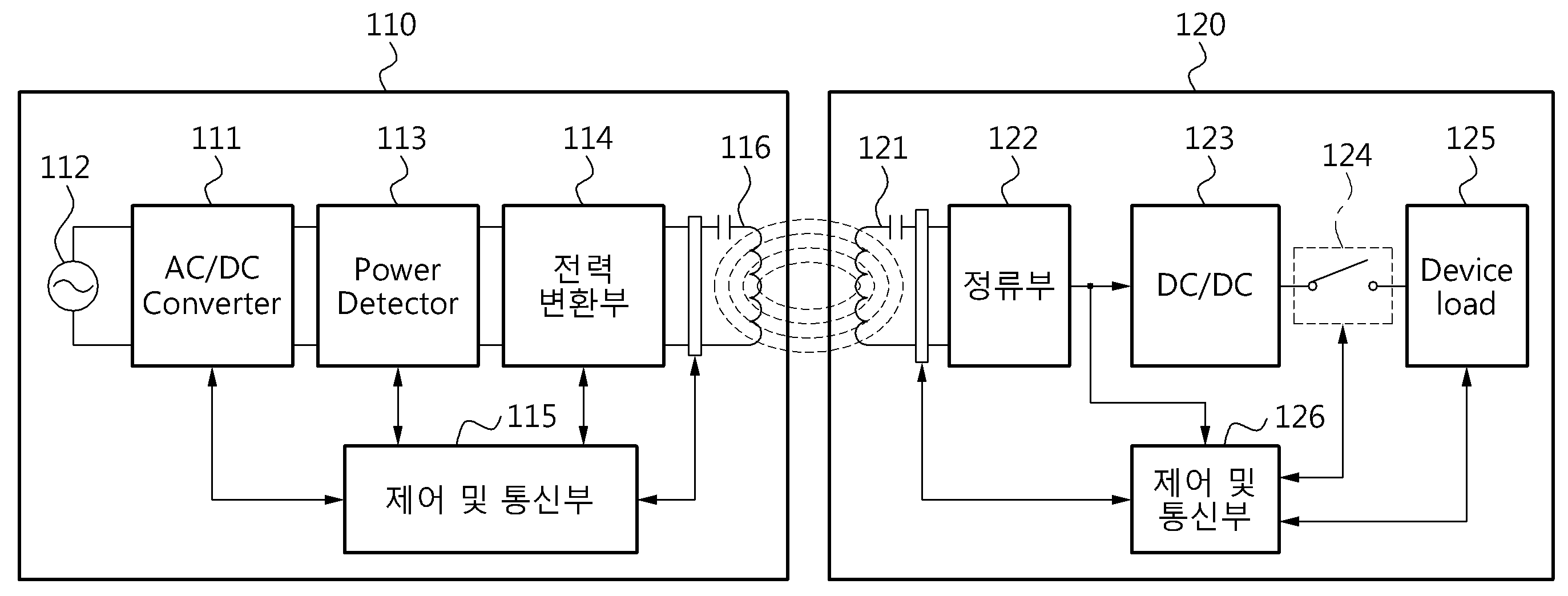
도 1은 일 실시 예에 따른 무선 전력 전송 및 충전 시스템을 나타낸다.1 illustrates a wireless power transmission and charging system according to an embodiment.
도 1을 참조하면, 일 실시 예에 따른 무선 전력 전송 및 충전 시스템은 소스 디바이스(110) 및 타겟 디바이스(120)를 포함한다.Referring to FIG. 1, a wireless power transmission and charging system according to an embodiment includes a
소스 디바이스(110)는 AC/DC 컨버터(111), Power Detector(113), 전력변환부(114), 제어 및 통신부(115) 및 소스 공진기(116)을 포함한다.The
타겟 디바이스(120)는 타겟 공진기(121), 정류부(122), DC/DC 컨버터(123), 스위치부(124), 디바이스 로드(Device load)(125) 및 제어 및 통신부(126)를 포함한다. 또한, 타겟 디바이스(120)는 통신 모듈(도시 되지 않음)을 더 포함할 수 있다. 이때, 통신 모듈은 블루투스(Bluetooth) 또는 무선랜(WLAN)과 같은 통신 회로를 포함할 수 있다. The
AC/DC 컨버터(111)는 Power Supply(112)로부터 출력되는 수십 Hz 대역의 AC 전압을 정류하여 DC 전압을 생성한다. AC/DC 컨버터(111)는 일정한 레벨의 DC 전압을 출력하거나, 제어 및 통신부(115)의 제어에 따라 DC 전압의 출력 레벨을 조정할 수 있다.The AC /
Power Detector(113)는 AC/DC 컨버터(111)의 출력 전류 및 전압을 검출하고, 검출된 전류 및 전압에 대한 정보를 제어 및 통신부(115)로 전달한다. 또한, Power Detector(113)는 전력변환부(114)의 입력 전류 및 전압을 검출할 수 도 있다.The
전력변환부(114)는 공진 주파수를 이용하여 직류 전압을 교류 전압으로 변환하여 웨이크-업(wake-up) 전력 또는 충전 전력을 생성한다. The
전력변환부(114)는 수십 KHz ~ 수십 MHz 대역의 스위칭 펄스 신호에 의하여 일정한 레벨의 DC 전압을 AC 전압으로 변환함으로써 전력을 생성할 수 있다. 즉, 전력변환부(114)는 공진 주파수를 이용하여 직류 전압을 교류 전압으로 변환함으로써, 타겟 디바이스에서 사용되는 "웨이크-업 전력" 또는 "충전 전력"을 생성할 수 있다. 여기서, 통신용 전력은 0.1~1mWatt의 작은 전력을 의미하고, 충전용 전력은 타겟 디바이스의 디바이스 로드에서 소비되는 1mWatt~200Watt의 큰 전력을 의미한다. 본 명세서에 있어서, "충전"이라는 용어는 전력을 충전하는 유닛(unit) 또는 요소(element)에 전력을 공급하는 의미로 사용될 수 있다. 또한, "충전"이라는 용어는 전력을 소비하는 유닛(unit) 또는 요소(element)에 전력을 공급하는 의미로도 사용될 수 있다. 예를 들어, "충전 전력"은 타겟 디바이스의 배터리를 충전하는데 필요한 전력 또는 타겟 디바이스의 동작에 소비되는 전력을 의미한다. 여기서, 유닛(unit) 또는 요소(element)는 예를 들어 배터리, 디스플레이, 음성 출력 회로, 메인 프로세서, 각종 센서들을 포함한다.The
한편, 본 명세서에서 "기준 공진 주파수"는 소스 디바이스(110)가 기본적으로 사용하는 공진 주파수의 의미로 사용된다. 또한, "트래킹 주파수"는 기 설정된 방식에 따라 조정된 공진 주파수의 의미로 사용된다. In the present specification, the "reference resonance frequency" is used as a meaning of the resonance frequency that the
제어 및 통신부(115)는 스위칭 펄스 신호의 주파수를 제어할 수 있다. 제어 및 통신부(115)의 제어에 의하여 스위칭 펄스 신호의 주파수가 결정될 수 있다.The control and
제어 및 통신부(115)는 통신 채널을 이용하는 아웃-밴드 통신을 수행할 수 도 있다. 제어 및 통신부(115)는 Zigbee, Bluetooth 등의 통신 모듈을 포함할 수 있다. 제어 및 통신부(115)는 아웃-밴드 통신을 통해 타겟 디바이스(120)와 데이터를 송수신 할 수 있다.The control and
제어부 및 통신부(126)는 타겟 디바이스(120)와 통신을 수행하기 위한 제어용 통신 채널을 선택한다. 또한, 제어부 및 통신부(126)는 캐리어(carrier) 신호의 검출에 기초하여 사용 가능한 제어용 통신 채널을 검색하고, 상기 사용 가능한 제어용 통신 채널의 검색을 통해 상기 타겟 디바이스(120)와 통신을 수행하기 위한 제어용 통신 채널을 선택하고, 상기 선택된 제어용 통신 채널을 통해 채널 고정 명령어 및 상기 소스 디바이스의 식별자를 포함하는 초기 제어 신호를 상기 타겟 디바이스(120)에게 전송한다. The control unit and the
또한, 제어부 및 통신부(126)는 N개(N은 2이상의 정수) 통신 채널들 중 제1 통신 채널을 선택하고, 상기 제1 통신 채널을 통해 상기 캐리어 신호가 검출되는 지를 판단하고, 상기 캐리어 신호가 검출되면, 검출된 캐리어 신호의 신호 레벨이 기 설정된 값 이상인지 여부를 판단하고, 상기 캐리어 신호의 신호 레벨이 기 설정된 값 이상이면, 상기 N개의 통신 채널들 중 제2 통신 채널을 선택하고, 상기 제2 통신 채널을 통해 상기 캐리어 신호가 검출되는 지를 판단할 수 있다. In addition, the control unit and the
제어 및 통신부(115)는 아웃-밴드 통신을 통해 초기 통신을 위한 웨이크-업 요청 신호를 상기 타겟 디바이스로 전송하고, 상기 타겟 디바이스로부터 상기 웨이크-업 요청 신호의 수신 감도에 대한 정보 및 상기 충전 전력의 수신 레벨에 대한 정보 중 적어도 어느 하나를 수신한다. 여기서, 제어 및 통신부(115)는 상기 웨이크-업 요청 신호의 수신 감도에 대한 정보 및 상기 충전 전력의 수신 레벨에 대한 정보 중 적어도 어느 하나에 기초하여, 상기 소스 디바이스의 전력 전송 영역 내에 위치하는 타겟 디바이스를 검출할 수 있다. 제어 및 통신부(115)는 상기 웨이크-업 요청 신호의 수신 감도가 기 설정된 값 이상이고 상기 충전 전력의 수신 레벨이 기 설정된 레벨 이상인 경우, 상기 웨이크-업 요청 신호의 수신 감도에 대한 정보 및 상기 충전 전력의 수신 레벨에 대한 정보를 전송한 타겟 디바이스를 상기 소스 디바이스의 전력 전송 영역 내에 위치하는 타겟 디바이스로 결정할 수 있다. The control and
제어 및 통신부(115)는 아웃-밴드 통신을 통해 초기 통신을 위한 웨이크-업 요청 신호를 상기 타겟 디바이스로 전송하고, 상기 충전 전력의 전송 타이밍을 제어하고, 상기 타겟 디바이스로부터 상기 웨이크-업 요청 신호의 수신 감도에 대한 정보, 상기 타겟 디바이스의 웨이크-업 시간 및 상기 충전 전력의 수신 타이밍에 대한 정보 중 적어도 어느 하나를 수신할 수 있다. 여기서, 제어 및 통신부(115)는 상기 웨이크-업 요청 신호의 수신 감도에 대한, 상기 타겟 디바이스의 웨이크-업 시간 및 상기 충전 전력의 수신 타이밍에 대한 정보 중 적어도 어느 하나에 기초하여, 상기 소스 디바이스의 전력 전송 영역 내에 위치하는 타겟 디바이스를 검출할 수 있다. 제어 및 통신부(115)는 상기 웨이크-업 요청 신호의 수신 감도가 기 설정된 값 이상이고 상기 충전 전력의 수신 타이밍에 대한 정보가 상기 기 설정된 전송 타이밍과 매칭되는 경우, 상기 웨이크-업 요청 신호의 수신 감도에 대한 정보 및 상기 충전 전력의 수신 타이밍에 대한 정보를 전송한 타겟 디바이스를 상기 소스 디바이스의 전력 전송 영역 내에 위치하는 타겟 디바이스로 결정할 수 있다. The control and
소스 공진기(116)는 전자기(electromagnetic) 에너지를 타겟 공진기(121)로 전달(transferring)한다. 즉, 소스 공진기(116)는 타겟 공진기(121)와의 마그네틱 커플링을 통해 "웨이크-업 전력" 또는 "충전 전력"을 타겟 디바이스(120)로 전달한다.The
타겟 공진기(121)는 소스 공진기(116)로부터 전자기(electromagnetic) 에너지를 수신한다. 즉, 타겟 공진기(121)는 소스 공진기(116)와의 마그네틱 커플링을 통해 소스 디바이스(110)로부터 통신 및 제어 기능을 활성화 시키는 "웨이크-업 전력" 또는 충전을 위한 "충전 전력"을 수신한다. The
정류부(122)는 교류 전압을 정류함으로써, DC 전압을 생성한다. 즉, 정류부(122)는 타겟 공진기(121)에 수신된 교류 전압을 정류한다. The
DC/DC 컨버터(123)는 정류부(122)에서 출력되는 DC 전압의 레벨을 디바이스 로드(125)의 용량에 맞게 조정한다. 예를 들어, DC/DC 컨버터(123)는 정류부(122)에서 출력되는 DC 전압의 레벨을 3~10Volt로 조정할 수 있다. The DC /
스위치부(124)는 제어 및 통신부(126)의 제어에 따라 온/오프 된다. 스위치부(124)가 오프되는 경우, 소스 디바이스(110)의 제어 및 통신부(115)는 반사파를 검출하게 된다. 즉, 스위치부(124)가 오프되는 경우, 소스 공진기(116)와 타겟 공진기(121) 사이의 마그네틱 커플링이 제거 될 수 있다. The
디바이스 로드(125)는 전력을 소비하는 유닛에 의해 형성되는 로드이다. 디바이스 로드(device load)(125)는 배터리, 디스플레이, 음성 출력 회로, 메인 프로세서, 각종 센서들을 포함할 수 있다. 즉, 디바이스 로드(125)는 배터리를 포함할 수 있다. 이때, 디바이스 로드(125)는 DC/DC 컨버터(123)로부터 출력되는 DC 전압을 이용하여 배터리를 충전할 수 있다.The
도 1에서, 제어 및 통신부(126) 및 통신 모듈은 상기 웨이크-업 전력에 의해 활성화될 수 있다. 제어 및 통신부(126)는 상기 웨이크-업 전력에 의해 활성화되고, N개(N은 2이상의 정수) 통신 채널들 중 제1 통신 채널을 선택한다. 이때, 제어 및 통신부(126)는 상기 제1 통신 채널을 통해 캐리어 신호가 검출되는지를 판단하고, 상기 제1 통신 채널을 통해 상기 캐리어 신호가 검출되면 상기 소스 디바이스로부터 채널 고정 명령어를 포함하는 초기 제어 신호가 수신되는지 여부를 판단하고, 상기 초기 제어 신호가 수신되면, 상기 채널 고정 명령어에 대한 응답 신호를 상기 소스 디바이스(110)로 전송한다. 또한, 제어 및 통신부(126)는 상기 제1 통신 채널을 통해 상기 캐리어 신호가 검출되지 않으면, 상기 N개의 통신 채널들 중 제2 통신 채널을 선택하고 상기 제2 통신 채널을 통해 상기 캐리어 신호가 검출되는 지를 판단할 수 있다. In FIG. 1, the control and
통신 모듈은 상기 웨이크-업 전력에 의해 활성화되고, 상기 소스 디바이스로부터 초기 통신을 위한 웨이크-업 요청 신호를 수신하고, 상기 웨이크-업 요청 신호의 수신 감도에 대한 정보 및 상기 충전 전력의 수신 레벨에 대한 정보를 상기 소스 디바이스(110)로 전송한다. 통신 모듈은 아웃-밴드 통신을 통해 소스 디바이스(110)와 데이터를 송수신 할 수 있다.The communication module is activated by the wake-up power, receives a wake-up request signal for initial communication from the source device, and provides information on the reception sensitivity of the wake-up request signal and the reception level of the charging power. Information about the
제어부 및 통신부(126)는 상기 웨이크-업 요청 신호의 수신 감도, 상기 충전 전력의 수신 레벨, 및 상기 충전 전력의 수신 타이밍에 대한 정보를 검출한다. 충전 전력의 수신 레벨 및 충전 전력의 수신 타이밍에 대한 정보는 타겟 공진기(121)와 정류부(122) 사이 또는 정류부(122)와 DC/DC 컨버터(123) 사이에서 측정될 수 있다.
The control unit and the
도 2는 일 실시 예에 따른 멀티 소스 환경을 나타내는 예시도이다.2 illustrates an example of a multi-source environment according to an exemplary embodiment.
도 2를 참조하면, 멀티 소스 환경은 복수의 소스 디바이스들(211, 221)을 포함한다. Source Device 1(211)의 전력 전송 영역(210)은 Source Device 2(221)의 전력 전송 영역(220)과 겹치지 않도록 설정될 수 있다. Source Device 2(221)는 Source Device 1(211)으로부터 기 설정된 거리 내에 위치한 이웃 소스 디바이스라 칭할 수 있다. Referring to FIG. 2, the multi-source environment includes a plurality of
Target Device 1(213) 및 Target Device 2(215)는 Source Device 1(211)의 전력 전송 영역(210) 내에 위치한다. Target Device 3(223)은 Source Device 2(221)의 전력 전송 영역(220) 내에 위치한다. 따라서, Target Device 3(223)의 타겟 공진기는 마그네틱 커플링을 통해 Source Device 2(221)로부터 통신 및 제어 기능을 활성화 시키는 웨이크-업(wake-up) 전력을 수신할 수 있다. The
멀티 소스 환경에서 아웃 밴드 통신을 사용하면, Source Device 1(211)의 통신 가능 영역(230)은 전력 전송 영역(210) 보다 넓게 형성될 수 있다. 복수의 소스 디바이스들(211, 221) 각각은, 전력 전송이 가능한 영역 내에 존재하는 타겟 디바이스를 정확하게 검출하여야 한다. Target Device 3(223)은 Source Device 2(221)의 전력 전송 영역(220) 내에 위치하지만, Source Device 1(211)의 통신 가능 영역(230) 내에도 위치한다. 따라서, Target Device 3(223)의 통신모듈은 Source Device 2(221)로부터 수신된 웨이크-업 전력에 의해 활성화되고, Source Device 1(211)으로부터 초기 통신을 위한 웨이크-업 요청 신호를 수신할 수 있다. Target Device 3(223)은 웨이크-업 전력을 Source Device 2(221)로부터 수신하고, 웨이크-업 요청 신호를 Source Device 1(211)로부터 수신할 수 있다. Source Device 1(211)으로부터 초기 통신을 위한 웨이크-업 요청 신호를 수신한 경우, Target Device 3(223)의 통신모듈은 상기 웨이크-업 요청 신호의 수신 감도에 대한 정보를 Source Device 1(211)로 전송하여야 한다. When out-band communication is used in a multi-source environment, the
Source Device 1(211)은 Target Device 3(223)이 전력 전송 영역(210) 내에 위치하지 않음을 검출하여야 한다. Source Device 1(211)은 전력 전송 영역(220) 내에 위치하는 Target Device 1(213) 및 Target Device 2(215)에 제어 ID를 부여한다. 여기서, 제어 ID는 충전 모드에서 소스 디바이스가 타겟 디바이스를 식별하기 위한 식별자이다.
The
도 3은 일 실시 예에 따른 무선 전력 전송 및 충전 시스템의 동작 모드를 설명하기 위한 도면이다. 3 is a diagram illustrating an operation mode of a wireless power transmission and charging system according to an exemplary embodiment.
도 3을 참조하면, 무선 전력 전송 및 충전 시스템의 동작 모드는 크게 대기 모드, 접속 모드 및 충전 모드로 구분된다. 대기 모드는 소스 디바이스의 전력 전송 영역 내에 타겟 디바이스가 존재하지 않기 때문에 소스 디바이스가 아무런 동작을 하지 않는 상태를 나타낸다. 대기 모드가 특정 이벤트에 의해 종료되면, 소스 디바이스는 아웃 밴드 통신을 수행하기 위한 채널을 검색한다. 여기서, 특정 이벤트는 타겟 디바이스가 검출된 경우를 의미한다. 예를 들어, 타겟 디바이스는 특정 센서에 의해 감지될 수 있다. 또한, 소스 디바이스는 일정 주기로 웨이크-업 전력을 전송하고, 임피던스 변화 또는 반사파의 변화를 검출함으로써, 타겟 디바이스를 검출할 수 도 있다. 소스 디바이스는 복수의 통신 채널을 검출하고, 복수의 통신 채널 중 채널 상태가 가장 좋은 채널을 선택한다. 채널 상태가 가장 좋은 채널이 선택되면, 소스 디바이스는 접속 모드로 동작한다. 소스 디바이스는 채널 상태가 가장 좋은 채널을 통해 상기 웨이크-업 요청 신호를 전송할 수 있다. 접속 모드는 소스 디바이스와 타겟 디바이스가 통신을 통해 데이터를 송수신하는 모드이다. 충전 모드는 충전 전력을 전달하는 모드이다. 도 3에 도시된 동작 모드는 예시적인 것일 뿐, 다양한 동작 모드가 있을 수 있다. 충전 모드에서 소스 디바이스는, 통신 채널의 품질을 확인하고 통신 채널 변경 모드로 동작할 수 있다. 이때, 통신 채널 변경은 아웃 밴드 통신을 통해 수행되기 때문에, 충전 전력의 전송은 끊김 없이 수행될 수 있다. 통신 채널 변경 모드에서 소스 디바이스는 통신 채널의 품질을 확인하고, 통신 채널 변경을 요청하기 위한 명령어를 타겟 디바이스로 전송할 수 있다.Referring to FIG. 3, operation modes of the wireless power transmission and charging system are largely divided into a standby mode, a connection mode, and a charging mode. The standby mode indicates a state in which the source device does not operate because there is no target device in the power transmission area of the source device. When the standby mode is terminated by a specific event, the source device searches for a channel for performing out band communication. Here, the specific event means a case where the target device is detected. For example, the target device can be sensed by a particular sensor. In addition, the source device may detect the target device by transmitting wake-up power at regular intervals and detecting a change in impedance or a change in the reflected wave. The source device detects a plurality of communication channels and selects a channel having the best channel state among the plurality of communication channels. When the channel with the best channel condition is selected, the source device operates in connected mode. The source device may transmit the wake-up request signal through the channel having the best channel condition. The connection mode is a mode in which a source device and a target device transmit and receive data through communication. The charging mode is a mode for delivering charging power. The operation mode illustrated in FIG. 3 is merely exemplary, and there may be various operation modes. In the charging mode, the source device can check the quality of the communication channel and operate in the communication channel change mode. At this time, since the communication channel change is performed through the out-band communication, the transmission of the charging power can be performed without interruption. In the communication channel change mode, the source device may check a quality of the communication channel and transmit a command for requesting the communication channel change to the target device.
도 3에서, 채널 대기 모드는 캐리어 신호의 검출을 준비하는 모드이다. 소스 디바이스는 채널 대기 모드에서 캐리어 신호를 검출하기 위한 회로를 활성화 시킬 수 있다. 채널 검색 모드는 캐리어 신호를 검출함으로써, 빈 채널을 검색하는 모드이다. 채널 선택 모드는 캐리어 신호의 검출 여부 및 캐리어 신호의 신호 레벨에 기초하여 제어용 통신 채널을 선택하는 모드이다. 또한, 채널 선택 모드에서 타겟 디바이스는 채널 검색을 수행하여 상기 제어용 통신 채널을 선택한다. 즉, 타겟 디바이스는 웨이크-업되면, 제어용 통신 채널을 찾기 위한 동작을 수행할 수 있다. In Fig. 3, the channel standby mode is a mode for preparing for detection of a carrier signal. The source device may activate circuitry for detecting a carrier signal in channel standby mode. The channel search mode is a mode for searching for an empty channel by detecting a carrier signal. The channel selection mode is a mode for selecting a control communication channel based on whether a carrier signal is detected and the signal level of the carrier signal. In addition, in the channel selection mode, the target device selects the control communication channel by performing a channel search. That is, when the target device wakes up, the target device may perform an operation for finding a control communication channel.
1부터 N번까지의 채널이 있는 경우, 소스 디바이스는 몇 번 채널부터 검색할 것인지를 결정할 수 있다. 채널 검색의 순서는 내림 차순 또는 올림 차순 또는 랜덤한 방식이 모두 가능하다. 또한, 채널 검색의 순서는 소스 디바이스의 종류나 소스 디바이스에 부여된 고유 식별자에 따라 다르게 설정될 수 있다. 채널 검색의 순서가 소스 디바이스의 종류나 소스 디바이스에 부여된 고유 식별자에 따라 다르게 설정되면, 멀티 소스 환경에서 채널 간 충돌을 피할 수 도 있다. 표 1은 소스 디바이스의 종류나 소스 디바이스에 부여된 고유 식별자에 따라 다르게 설정된 채널 검색 순서의 예이다. If there are
[표 1]TABLE 1

도 4는 일 실시예에 따른 소스 디바이스의 채널 선택 방법을 설명하기 위한 예시도이다. 4 is an exemplary diagram for describing a channel selection method of a source device according to an embodiment.
소스 디바이스는 N개의 채널들 각각의 채널 상태를 순차적으로 확인하거나, 랜덤하게 확인할 수 있다. 도 4에서 410은 1번 채널인 Ch1의 채널 상태를 확인하는 시간 구간을 나타낸다. 도 4에서 420은 2번 채널인 Ch2의 채널 상태를 확인하는 시간 구간을 나타낸다. 도 4에서 430은 N번 채널인 ChN의 채널 상태를 확인하는 시간 구간을 나타낸다.The source device may check the channel status of each of the N channels sequentially or randomly. In FIG. 4, 410 represents a time interval for checking the channel state of Ch1, which is
소스 디바이스는 시간구간 411에서 Ch1의 캐리어 신호의 검출을 준비한다. 즉, 시간구간 411은 도 3의 채널 대기 모드에 해당한다. 소스 디바이스는 시간구간 413에서 Ch1의 캐리어 신호를 기 설정된 횟수만큼 측정한다. 소스 디바이스는 시간구간 415에서 Ch1의 캐리어 신호의 레벨이 기 설정된 값 이상인지를 확인한다. 만일 캐리어 신호의 신호 레벨이 기 설정된 값 이상이면, 해당 채널은 다른 소스 디바이스에 의해 사용중인 채널일 수 있다. Ch1의 캐리어 신호의 레벨이 기 설정된 값 이상이면, 소스 디바이스는 시간구간 420에서 Ch2의 채널 상태를 확인한다. Ch1의 캐리어 신호의 레벨이 기 설정된 값보다 작으면, 소스 디바이스는 Ch1을 타겟 디바이스와 통신을 수행하기 위한 제어용 통신 채널로 선택할 수 있다. The source device prepares for detection of a carrier signal of Ch1 at
한편, Ch1 부터 Ch N-1 까지의 모든 채널이 다른 소스 디바이스에 의해 사용 중이면, 소스 디바이스는 시간 구간 430에서 ChN의 채널 상태를 확인한다. 소스 디바이스는 시간구간 431에서 ChN의 캐리어 신호의 검출을 준비한다. 소스 디바이스는 시간구간 433에서 ChN의 캐리어 신호를 기 설정된 횟수 만큼 측정한다. 소스 디바이스는 시간구간 435에서 ChN의 캐리어 신호의 레벨이 기 설정된 값 이상인지를 확인한다. 만일, ChN 도 다른 소스 디바이스에 의해 사용중인 것으로 판단되면, 소스 디바이스는 1번 채널인 Ch1의 채널 상태를 다시 확인할 수 있다.
On the other hand, if all channels from Ch1 to Ch N-1 are in use by another source device, the source device checks the channel state of ChN at
도 5는 일 실시예에 따른 소스 디바이스의 구성 예를 간략하게 나타낸 도면이다. 5 is a diagram schematically illustrating an example of a configuration of a source device according to an exemplary embodiment.
도 5를 참조하면, 소스 디바이스(500)은 소스 공진기(510), 전력 변환부(520), 통신부(530) 및 Carrier Detector(540)을 포함할 수 있다. 여기서, 통신부(530)는 아웃 밴드 통신을 수행한다. Carrier Detector(540)는 신호의 레벨을 비교하기 위한 비교기 및 아날로그 신호를 디지털 신호로 변환하는 AD 컨버터를 포함할 수 있다.
Referring to FIG. 5, the
도 6은 다른 일 실시예에 따른 소스 디바이스의 구성 예를 간략하게 나타낸 도면이다. 6 is a diagram schematically illustrating an example of a configuration of a source device according to another exemplary embodiment.
도 6을 참조하면, 소스 디바이스(600)은 소스 공진기(610), 전력 변환부 & 통신부(620) 및 Carrier Detector(630)을 포함할 수 있다. 여기서, 전력 변환부 & 통신부(620)는 도 1의 전력변환부(114)의 기능 및 인-밴드 통신을 수행한다. 인-밴드 통신은, 공진 주파수를 이용하여 데이터를 송수신하는 통신 방식이다.
Referring to FIG. 6, the
도 7 및 도 8은 일 실시예에 따른 통신 채널 할당 및 전력 전송 방법을 나타내는 흐름도이다. 7 and 8 are flowcharts illustrating a communication channel allocation and power transmission method according to an embodiment.
도 7 및 도 8에 도시된 방법은, 소스 디바이스에 의해 수행될 수 있다. The method shown in FIGS. 7 and 8 may be performed by a source device.
소스 디바이스는 710 단계에서 Target Device가 검출되는 지를 판단한다. 즉, 소스 디바이스는 710 단계에서 대기 모드로 동작할 수 있다. The source device determines whether the target device is detected in
소스 디바이스로부터 무선으로 전력을 수신하는 타겟 디바이스가 검출되면, 소스 디바이스는 720단계에서 상기 타겟 디바이스와 통신을 수행하기 위한 제어용 통신 채널을 선택한다. If a target device that wirelessly receives power from the source device is detected, the source device selects a control communication channel for performing communication with the target device in
이때, 제어용 통신 채널을 선택하는 방법은 도 8의 811 단계 내지 817 단계를 포함할 수 있다. 즉, 소스 디바이스는 811단계에서 타겟 디바이스의 통신 기능 및 제어 기능을 활성화 시키는 웨이크-업 전력을 상기 타겟 디바이스로 전송한다. In this case, the method of selecting a control communication channel may include
소스 디바이스는 813 단계 내지 817 단계에서 캐리어(carrier) 신호의 검출에 기초하여 사용 가능한 제어용 통신 채널을 검색하고, 사용 가능한 제어용 통신 채널의 검색을 통해 상기 타겟 디바이스와 통신을 수행하기 위한 제어용 통신 채널을 선택할 수 있다. 즉, 소스 디바이스는 813단계에서, 최초의 채널을 선택한다. 즉, 소스 디바이스는 813단계에서 N개(N은 2이상의 정수) 통신 채널들 중 제1 통신 채널을 선택한다. The source device searches for the available control communication channel based on the detection of the carrier signal in
소스 디바이스는 815 단계에서 최초의 채널이 빈 채널인지를 판단한다. 즉, 소스 디바이스는 815 단계에서 상기 제1 통신 채널을 통해 상기 캐리어 신호가 검출되는 지를 판단하고, 상기 캐리어 신호가 검출되면, 검출된 캐리어 신호의 신호 레벨이 기 설정된 값 이상인지 여부를 판단한다. The source device determines in
만일, 검출된 캐리어 신호의 신호 레벨이 기 설정된 값 보다 작으면, 제1 통신 채널은 빈 채널에 해당된다. If the signal level of the detected carrier signal is smaller than the preset value, the first communication channel corresponds to an empty channel.
만일, 상기 제1 통신 채널을 통해 상기 캐리어 신호가 검출되지 않거나, 상기 제1 통신 채널을 통해 수신된 상기 캐리어 신호의 신호 레벨이 상기 기 설정된 값 보다 작으면, 소스 디바이스는 상기 제1 통신 채널을 상기 제어용 통신 채널로 선택할 수 있다. 만일, 검출된 캐리어 신호의 신호 레벨이 기 설정된 값 이상이면, 소스 디바이스는 상기 N개의 통신 채널들 중 제2 통신 채널을 선택하고, 상기 제2 통신 채널을 통해 상기 캐리어 신호가 검출되는 지를 판단하는 단계를 수행한다. If the carrier signal is not detected through the first communication channel, or if the signal level of the carrier signal received through the first communication channel is smaller than the preset value, the source device disconnects the first communication channel. The control communication channel can be selected. If the signal level of the detected carrier signal is greater than or equal to a preset value, the source device selects a second communication channel among the N communication channels, and determines whether the carrier signal is detected through the second communication channel. Perform the steps.
즉, 소스 디바이스는 817단계 및 819단계를 수행함으로써, 모든 채널에 대해 빈 채널인지 여부를 판단할 수 있다. 소스 디바이스는 817단계에서 모든 채널에 대해 검색이 진행되었는지를 판단한다. 모든 채널에 대해 검색이 진행된 경우, 소스 디바이스는 813 단계를 다시 수행한다. 만일, 모든 채널에 대해 검색이 진행되지 않은 경우, 소스 디바이스는 819단계에서 채널 번호를 변경하고, 다시 815 단계를 수행할 수 있다. That is, the source device may determine whether the channel is empty for all channels by performing
소스 디바이스는 730단계에서, 상기 선택된 제어용 통신 채널을 통해 채널 고정 명령어 및 상기 소스 디바이스의 식별자를 포함하는 초기 제어 신호를 상기 타겟 디바이스에게 전송한다. 여기서, 채널 고정 명령어는 상기 선택된 제어용 통신 채널을 사용하도록 상기 타겟 디바이스에게 요청하는 명령어이다. 여기서, 상기 초기 제어 신호는 상기 타겟 디바이스가 상기 N개의 통신채널을 스캔하는 시간을 고려하여 연속적인 시간 동안 전송될 수 있다. 예를 들어, 타겟 디바이스에서 N개의 통신채널을 모두 스캔하는데 소요되는 시간이 1ms이면, 상기 초기 제어 신호는 1ms동안 끊어짐 없이 전송될 수도 있다. 통신 채널을 스캔하는 시간은 통신 규격에 따라 다양하게 설정될 수 있다. In
소스 디바이스는 740단계에서, 타겟 디바이스로부터 상기 채널 고정 명령어에 대한 응답 신호가 수신되는지를 판단한다. 만일, 기 설정된 시간 내에 상기 채널 고정 명령어에 대한 응답 신호가 수신되지 않으면, 소스 디바이스는 750단계를 수행한다. 상기 채널 고정 명령어에 대한 응답 신호가 수신되면, 소스 디바이스는 760단계를 수행한다. In
소스 디바이스는 750단계에서, 초기 제어 신호의 전송 횟수가 기 설정된 횟수를 초과했는지를 판단한다. 기 설정된 횟수를 초과한 경우 타겟 디바이스의 검출은 오류로 처리된다. In
소스 디바이스는 760단계에서, 타겟 디바이스에 제어용 ID를 할당하고, 상기 타겟 디바이스의 충전을 위한 충전 전력을 상기 타겟 디바이스로 전송하는 충전 모드로 진입한다. 충전 모드에서, 소스 디바이스는 도 9 내지 도 11에 도시된 방법들을 병렬적으로 수행하거나, 선택적으로 수행할 수 있다.
In
도 9는 다른 일 실시예에 따른 통신 채널 할당 및 전력 전송 방법을 나타내는 흐름도이다.9 is a flowchart illustrating a communication channel allocation and power transmission method according to another embodiment.
도 9를 참조하면, 소스 디바이스는 910단계에서 통신 오류가 발생하는지를 판단한다. 즉, 소스 디바이스는 충전 모드에서 통신 오류가 발생하는지를 판단한다. 9, the source device determines whether a communication error occurs in
충전 모드에서 통신 오류가 발생하면, 소스 디바이스는 N개(N은 2이상의 정수) 통신 채널들 중 빈 채널을 검색하고, 빈 채널로 제어용 통신 채널을 변경하기 위한 동작을 수행한다. When a communication error occurs in the charging mode, the source device searches for an empty channel among N communication channels (N is an integer of 2 or more), and performs an operation for changing the control communication channel to the empty channel.
소스 디바이스는 920단계에서 다음 채널을 선택한다. 여기서, 다음 채널이란, N개의 통신 채널 들 중 현재 사용하고 있는 제어용 통신 채널을 제외한 어느 한 채널일 수 있다. The source device selects the next channel in
소스 디바이스는 930단계에서, 선택된 다음 채널이 빈 채널인지를 판단한다. 만일, 다음 채널이 빈 채널이 아니면, 소스 디바이스는 940 단계 및 950단계에서 도 8의 817단계 및 819 단계와 동일한 동작을 수행한다. 또한, 소스 디바이스는 960단계에서, N개의 통신 채널들에 대한 검색 횟수가 기 설정된 횟수를 초과하는지를 판단한다. N개의 통신 채널들에 대한 검색 횟수가 기 설정된 횟수를 초과한 경우 채널 변경을 위한 절차는 오류 처리된다. In
930단계 내지 960단계를 수행한 결과 빈 채널이 검색되면, 소스 디바이스는 970단계에서 "선택된 제어용 통신 채널"을 통해 상기 타겟 디바이스로 채널 변경 명령어를 전송한다. 이때, 상기 "선택된 제어용 통신 채널"은 현재 사용 중인 제어용 통신 채널을 의미한다. 채널 변경 명령어는 검색된 빈 채널로 채널을 변경하도록 요청하는 명령어이다. If an empty channel is found as a result of performing
971단계에서 소스 디바이스는, 채널 변경 명령어에 대한 응답인 ACK 가 수신되는지를 판단한다. 소스 디바이스는 972단계에서 기 설정된 시간이 초과되었는지를 판단한다. 기 설정된 시간이 초과되면, 채널 변경을 위한 절차는 오류 처리된다. 기 설정된 시간 내에 ACK 가 수신되면, 소스 디바이스는 973단계에서 채널 변경을 수행한다. 즉, 소스 디바이스는 973단계에서, 채널 변경 명령어에 대한 응답을 수신하면, 상기 검색된 빈 채널로 상기 제어용 통신 채널을 변경한다. In
소스 디바이스는 974단계에서, 채널 변경이 정확하게 수행되었는지 여부를 확인할 수 있다. 즉, 소스 디바이스는 974단계에서 채널 변경 여부를 타겟 디바이스에 문의하고, 채널 변경 여부에 대한 ACK를 타겟 디바이스로부터 수신할 수 도 있다. 만일, 타겟 디바이스의 채널 변경 여부가 확인되지 않으면, 소스 디바이스는 채널 변경 절차를 오류로 처리할 수 있다. 타겟 채널 변경 여부가 확인되면 소스 디바이스는 충전 모드로 동작한다. 한편, 아웃-밴드 통신을 수행하는 경우, 전력 전송과 통신은 동시에 수행될 수 있다. 따라서, 도 9에 도시된 절차가 수행되는 시간구간에서도 전력의 전송은 끊어짐 없이 수행될 수 있다.
In
도 10은 다른 일 실시예에 따른 통신 채널 할당 및 전력 전송 방법을 나타내는 흐름도이다.10 is a flowchart illustrating a communication channel allocation and power transmission method according to another embodiment.
도 10에 도시된 방법은, 충전 모드에서 새로운 타겟 디바이스가 검출된 경우에 수행될 수 있다. The method shown in FIG. 10 may be performed when a new target device is detected in the charging mode.
충전 모드에서 새로운 타겟 디바이스가 검출되면, 소스 디바이스는 새로운 타겟 디바이스에 제어용 ID를 할당하고, 충전 전력의 레벨을 높인다. When a new target device is detected in the charging mode, the source device assigns a control ID to the new target device and raises the level of charging power.
도 10을 참조하면, 소스 디바이스는 1010단계에서, 새로운 타겟 디바이스가 검출되는지를 판단한다. 새로운 타겟 디바이스가 검출되면, 소스 디바이스는 1020단계에서 도 7의 710단계 내지 760단계를 수행함으로써, 새로운 타겟 디바이스에 제어용 ID를 할당한다. 10, in
소스 디바이스는 1020단계에서, 새로운 타겟 디바이스의 디바이스 로드를 고려하여 상기 충전 전력의 레벨을 조정한다. 예를 들어, 현재 전력을 수신하는 타겟 디바이스의 소비 전력이 5Watt이고, 새로운 타겟 디바이스의 소비 전력량이 5Watt인경우 충전 전력의 레벨은 5Watt에서 10Watt로 높여질 수 있다. In
한편, 도 2와 같이 멀티 소스 환경에서 새로운 타겟 디바이스가 Target Device 3(223)이고, 소스 디바이스가 Source Device 1(211)인 경우 문제가 될 수 있다. 따라서, 소스 디바이스는 1040단계에서 반사파를 검출한다. 만일, 새로운 타겟 디바이스가 Target Device 3(223)이고, 소스 디바이스가 Source Device 1(211)인 경우, 1040단계에서 검출되는 반사파의 레벨은 1030단계 이전에 검출되는 반사파의 레벨보다 큰 값을 갖는다. Meanwhile, as shown in FIG. 2, when the new target device is
소스 디바이스는 1050단계에서, 1040단계에서 검출된 반사파의 신호 레벨이 기 설정된 값 보다 큰 값인지를 판단한다. 만일, 검출된 반사파의 신호 레벨이 기 설정된 값 보다 크면, 소스 디바이스는 1070단계에서 상기 새로운 타겟 디바이스의 접속을 해제시킨다. 만일, 검출된 반사파의 신호 레벨이 기 설정된 값 보다 크지 않으면, 1060단계에서 충전 모드는 유지된다. 여기서, 충전 모드가 유지된다는 것은, 1030단계에서 조정된 충전 레벨을 유지하는 것을 의미한다.
In
도 11은 다른 일 실시예에 따른 통신 채널 할당 및 전력 전송 방법을 나타내는 흐름도이다.11 is a flowchart illustrating a communication channel allocation and power transmission method according to another embodiment.
도 11은 도 2와 같이 멀티 소스 환경에서 소스 디바이스가 자신의 전력 전송 영역에 위치하는 타겟 디바이스를 정확하게 검출하는 방법을 나타낸다. FIG. 11 illustrates a method of accurately detecting a target device located in its power transmission region in a multi-source environment as shown in FIG. 2.
소스 디바이스는 1110단계에서, 초기 제어 신호의 수신 감도에 대한 정보 및 상기 충전 전력의 수신 레벨에 대한 정보 중 적어도 어느 하나를 수신한다. In
소스 디바이스는 1120단계에서, 상기 초기 제어 신호의 수신 감도에 대한 정보 및 상기 충전 전력의 수신 레벨에 대한 정보 중 적어도 어느 하나에 기초하여 상기 타겟 디바이스가 상기 소스 디바이스의 전력 전송 영역 내에 위치하는지를 결정한다. In
상기 초기 제어 신호의 수신 감도가 기 설정된 레벨 이상이고, 상기 충전 전력의 수신 레벨이 기 설정된 레벨 이상인 경우, 소스 디바이스는 1130단계에서, 충전 전력의 전송을 유지한다. 만일, 상기 초기 제어 신호의 수신 감도가 기 설정된 레벨 이상이지만, 상기 충전 전력의 수신 레벨이 기 설정된 레벨 보다 작은 경우, 소스 디바이스는 1130단계에서 타겟 디바이스의 접속을 해제시킬 수 있다.
If the reception sensitivity of the initial control signal is greater than or equal to a preset level and the reception level of the charging power is greater than or equal to the preset level, the source device maintains transmission of the charging power in
도 12는 일 실시예에 따른 타겟 디바이스의 동작을 설명하기 위한 도면이다. 12 is a diagram for describing an operation of a target device, according to an exemplary embodiment.
도 12를 참조하면, 타겟 디바이스는 1210단계에서, 소스 디바이스로부터 통신 및 제어 기능을 활성화 시키는 웨이크-업(wake-up) 전력을 수신한다. 또한, 1210 단계에서 타겟 디바이스는 상기 웨이크-업 전력을 이용하여 통신 모듈을 활성화시킨다. Referring to FIG. 12, in
타겟 디바이스는 1220단계에서 최초의 채널을 선택한다. 이때, 최초의 채널은 N개의 통신 채널 중 어느 하나의 통신 채널일 수 있다. 즉, 타겟 디바이스는 1220단계에서, N개(N은 2이상의 정수) 통신 채널들 중 제1 통신 채널을 선택한다. The target device selects the first channel in
타겟 디바이스는 1230단계에서, 선택된 통신 채널이 사용중인 채널인지를 판단한다. 타겟 디바이스는 캐리어 신호의 검출여부 및 캐리어 신호의 레벨을 측정함으로써, 선택된 통신 채널이 사용중인 채널인지 여부를 판단할 수 있다. 즉, 타겟 디바이스는 1230단계에서, 제1 통신 채널을 통해 캐리어 신호가 검출되는지를 판단한다. In
타겟 디바이스는 1240 단계 내지 1260단계에서, 도 9의 940단계 내지 960단계와 동일한 동작을 수행할 수 있다. 따라서, 타겟 디바이스는 1240 단계 내지 1260단계에서, 상기 제1 통신 채널이 사용중인 채널이 아니면, 상기 N개의 통신 채널들 중 제2 통신 채널을 선택하고 상기 제2 통신 채널이 사용중인 채널인지를 판단할 수 있다. In
선택된 통신 채널이 사용중인 채널이면, 타겟 디바이스는 1270단계에서 소스 디바이스로부터 채널 고정 명령어를 포함하는 초기 제어 신호가 수신되는지 여부를 판단한다. 타겟 디바이스는 1280단계에서 기 설정된 시간이 초과되었는지를 판단한다. 기 설정된 시간이 초과되면, 소스 디바이스에 접속하기 위한 절차는 오류 처리된다. 기 설정된 시간 내에 초기 제어 신호가 수신되면, 타겟 디바이스는 1290단계에서 상기 채널 고정 명령어에 대한 응답 신호를 상기 소스 디바이스로 전송한다. 즉, 타겟 디바이스는 1290단계에서 상기 채널 고정 명령어에 대한 ACK를 소스 디바이스로 전송한다. If the selected communication channel is a busy channel, the target device determines whether an initial control signal including a channel fixed command is received from the source device in
이후, 타겟 디바이스는 충전 모드에서, 상기 소스 디바이스로부터 상기 타겟 디바이스의 충전을 위한 충전 전력을 수신한다. Thereafter, in the charging mode, the target device receives charging power for charging the target device from the source device.
한편, 타겟 디바이스는 도 10에 대응하는 동작을 수행할 수 도 있다. The target device may perform an operation corresponding to FIG. 10.
즉, 타겟 디바이스는 초기 제어 신호의 수신 감도에 대한 정보 및 상기 충전 전력의 수신 레벨에 대한 정보 중 적어도 어느 하나를 상기 소스 디바이스로 전송할 수 있다. That is, the target device may transmit at least one of the information on the reception sensitivity of the initial control signal and the information on the reception level of the charging power to the source device.
또한, 타겟 디바이스는 상기 초기 제어 신호의 수신 감도에 대한 정보 및 상기 충전 전력의 수신 레벨에 대한 정보 중 적어도 어느 하나에 기초하여 상기 소스 디바이스로부터 제어 ID를 할당 받을 수 있다.
In addition, the target device may be assigned a control ID from the source device based on at least one of the information on the reception sensitivity of the initial control signal and the information on the reception level of the charging power.
도 13은 일 실시예에 따른 소스 디바이스의 채널 탐색 방법을 설명하기 위한 예시도이다.FIG. 13 illustrates an example channel search method of a source device, according to an exemplary embodiment; FIG.
도 13에서 (a)는 소스 디바이스가 Ch8(즉, 8번 채널)을 제어용 통신 채널로 선택했음을 나타낸다. In FIG. 13, (a) shows that the source device has selected Ch8 (that is, channel 8) as the control communication channel.
도 13에서 (b)는 타겟 디바이스가 검색하는 채널들의 예를 나타낸다. 이때, 3번 채널(1301), 6번 채널(1303) 및 8번 채널(1305)은 사용중인 채널을 나타낸다. 따라서, 1번 채널 및 2번 채널을 통해서는 어떠한 캐리어 신호도 수신되지 않는다. 타겟 디바이스는 3번 채널이 사용중인 채널임을 알 수 있다. 따라서, 타겟 디바이스는 3번 채널(1301)을 통해 소스 디바이스의 초기 제어 신호가 수신되는 지를 판단할 수 있다. 소스 디바이스는 8번 채널을 통해 초기 제어 신호를 전송하고 있다. 따라서, 타겟 디바이스는 3번 채널(1301) 및 6번 채널(1303)을 통해 초기 제어 신호를 수신하지 못한다. 최종적으로, 타게 디바이스는 8번 채널(1305)을 통해 소스 디바이스의 초기 제어 신호를 수신할 수 있다.
In FIG. 13, (b) shows an example of channels searched by the target device. In this case, the
도 14는 일 실시예에 따른 공진기 및 피더에서 자기장의 분포를 나타낸다.14 illustrates a distribution of a magnetic field in a resonator and a feeder according to an embodiment.
별도의 피더를 통해 공진기가 전력을 공급받는 경우에는 피더에서 자기장이 발생하고, 공진기에서도 자기장이 발생한다. When the resonator is powered by a separate feeder, a magnetic field is generated in the feeder, and a magnetic field is generated in the resonator.
도 14의 (a)를 참조하면, 피더(1410)에서 입력 전류가 흐름에 따라 자기장(1430)이 발생한다. 피더(1410) 내부에서 자기장의 방향(1431)과 외부에서 자기장의 방향(1433)은 서로 반대 위상을 가진다. 피더(1410)에서 발생하는 자기장(1430)에 의해 공진기(1420)에서 유도 전류가 발생한다. 이때 유도 전류의 방향은 입력 전류의 방향과 반대이다.Referring to FIG. 14A, as the input current flows in the
유도 전류에 의해 공진기(1420)에서 자기장(1440)이 발생한다. 자기장의 방향은 공진기(1420)의 내부에서는 동일한 방향을 가진다. 따라서, 공진기(1420)에 의해 피더(1410)의 내부에서 발생하는 자기장의 방향(1441)과 피더(1410)의 외부에서 발생하는 자기장의 방향(1443)은 동일한 위상을 가진다. The
결과적으로 피더(1410)에 의해서 발생하는 자기장과 공진기(1420)에서 발생하는 자기장을 합성하면, 피더(1410)의 내부에서는 자기장의 세기가 약화되고, 피더(1410)의 외부에서는 자기장의 세기가 강화된다. 따라서, 도 14와 같은 구조의 피더(1410)를 통해 공진기(1420)에 전력을 공급하는 경우에, 공진기(1420) 중심에서 자기장의 세기가 약하고, 외곽에서 자기장의 세기가 강하다. 공진기(1420) 상에서 자기장의 분포가 균일(uniform)하지 않은 경우, 입력 임피던스가 수시로 변화하므로 임피던스 매칭을 수행하는 것이 어렵다. 또한, 자기장의 세기가 강한 부분에서는 무선 전력 전송이 잘되고, 자기장의 세기가 약한 부분에서는 무선 전력 전송이 잘 되지 않으므로, 평균적으로 전력 전송 효율이 감소한다.As a result, when the magnetic field generated by the
(b)는 공진기(1450)와 피더(1460)가 공통의 접지를 가진 무선 전력 전송 장치의 구조를 나타낸다. 공진기(1450)는 캐패시터(1451)를 포함할 수 있다. 피더(1460)는 포트(1461)를 통하여, RF 신호를 입력 받을 수 있다. 피더(1460)에는 RF 신호가 입력되어, 입력 전류가 생성될 수 있다. 피더(1460)에 흐르는 입력 전류는 자기장을 생성하고, 상기 자기장으로부터 공진기(1450)에 유도 전류가 유도된다. 또한, 공진기(1450)를 흐르는 유도 전류로부터 자기장이 발생한다. 이때, 피더(1460)에 흐르는 입력 전류의 방향과 공진기(1450)에 흐르는 유도 전류의 방향은 서로 반대 위상을 가진다. 따라서, 공진기(1450)와 피더(1460) 사이의 영역에서, 입력 전류에 의해 발생하는 자기장의 방향(1471)과 유도 전류에 의해 발생하는 자기장의 방향(1473)은 동일한 위상을 가지므로, 자기장의 세기가 강화된다. 반면에, 피더(1460)의 내부에서는, 입력 전류에 의해 발생하는 자기장의 방향(1481)과 유도 전류에 의해 발생하는 자기장의 방향(1483)은 반대 위상을 가지므로, 자기장의 세기가 약화된다. 결과적으로 공진기(1450)의 중심에서는 자기장의 세기가 약해지고, 공진기(1450)의 외곽에서는 자기장의 세기가 강화될 수 있다.
(b) shows the structure of the wireless power transmission apparatus in which the
도 15는 일 실시예에 따른 공진기 및 피더의 구성을 나타낸 도면이다. 15 is a diagram illustrating a configuration of a resonator and a feeder according to an exemplary embodiment.
도 15의 (a)를 참조하면, 공진기(1510)는 캐패시터(1511)를 포함할 수 있다. 피딩부(1520)는 캐패시터(1511)의 양단에 전기적으로 연결될 수 있다.Referring to FIG. 15A, the
(b)는 (a)의 구조를 좀 더 구체적으로 표시한 도면이다. 이때, 공진기(1510)는 제1 전송선로, 제1 도체(1541), 제2 도체(1542), 적어도 하나의 제1 캐패시터(1550)를 포함할 수 있다. (b) shows the structure of (a) in more detail. In this case, the
제1 캐패시터(1550)는 제1 전송 선로에서 제1 신호 도체 부분(1531)과 제2 신호 도체 부분(1532) 사이에 위치에 직렬로 삽입되며, 그에 따라 전계(electric field)는 제1 캐패시터(1550)에 갇히게 된다. 일반적으로, 전송 선로는 상부에 적어도 하나의 도체, 하부에 적어도 하나의 도체를 포함하며, 상부에 있는 도체를 통해서는 전류가 흐르며, 하부에 있는 도체는 전기적으로 그라운드 된다(grounded). 본 명세서에서는 제1 전송 선로의 상부에 있는 도체를 제1 신호 도체 부분(1531)과 제2 신호 도체 부분(1532)로 나누어 부르고, 제1 전송 선로의 하부에 있는 도체를 제1 그라운드 도체 부분(1533)으로 부르기로 한다.The
(b)에 도시된 바와 같이, 공진기는 2 차원 구조의 형태를 갖는다. 제1 전송 선로는 상부에 제1 신호 도체 부분(1531) 및 제2 신호 도체 부분(1532)을 포함하고, 하부에 제1 그라운드 도체 부분(1533)을 포함한다. 제1 신호 도체 부분(1531) 및 제2 신호 도체 부분(1532)과 제1 그라운드 도체 부분(1533)은 서로 마주보게 배치된다. 전류는 제1 신호 도체 부분(1531) 및 제2 신호 도체 부분(1532)을 통하여 흐른다.As shown in (b), the resonator has the form of a two-dimensional structure. The first transmission line includes a first
또한, (b)에 도시된 바와 같이 제1 신호 도체 부분(1531)의 한쪽 단은 제1 도체(1541)와 접지(short)되고, 다른 쪽 단은 제1 캐패시터(1550)와 연결된다. 그리고, 제2 신호 도체 부분(1532)의 한쪽 단은 제2 도체(1542)와 접지되며, 다른 쪽 단은 제1 캐패시터(1550)와 연결된다. 결국, 제1 신호 도체 부분(1531), 제2 신호 도체 부분(1532) 및 제1 그라운드 도체 부분(1533), 도체들(1541, 1542)은 서로 연결됨으로써, 공진기는 전기적으로 닫혀 있는 루프 구조를 갖는다. 여기서, '루프 구조'는 원형 구조, 사각형과 같은 다각형의 구조 등을 모두 포함하며, '루프 구조를 갖는다고 함은' 전기적으로 닫혀 있다는 것을 의미한다.In addition, as shown in (b), one end of the first
제1 캐패시터(1550)는 전송 선로의 중단부에 삽입된다. 보다 구체적으로, 제1캐패시터(1550)는 제1 신호 도체 부분(1531) 및 제2 신호 도체 부분(1532) 사이에 삽입된다. 이 때, 제1 캐패시터(1550)는 집중 소자(lumped element) 및 분산 소자(distributed element) 등의 형태를 가질 수 있다. 특히, 분산 소자의 형태를 갖는 분산된 캐패시터는 지그재그 형태의 도체 라인들과 그 도체 라인들 사이에 존재하는 높은 유전율을 갖는 유전체를 포함할 수 있다.The
제1 캐패시터(1550)가 전송 선로에 삽입됨에 따라 소스 공진기는 메타물질(metamaterial)의 특성을 가질 수 있다. 여기서, 메타물질이란 자연에서 발견될 수 없는 특별한 전기적 성질을 갖는 물질로서, 인공적으로 설계된 구조를 갖는다. 자연계에 존재하는 모든 물질들의 전자기 특성은 고유의 유전율 또는 투자율을 가지며, 대부분의 물질들은 양의 유전율 및 양의 투자율을 갖는다. As the
대부분의 물질들에서 전계, 자계 및 포인팅 벡터에는 오른손 법칙이 적용되므로, 이러한 물질들을 RHM(Right Handed Material)이라고 한다. 그러나, 메타물질은 자연계에 존재하지 않는 유전율 또는 투자율을 가진 물질로서, 유전율 또는 투자율의 부호에 따라 ENG(epsilon negative) 물질, MNG(mu negative) 물질, DNG(double negative) 물질, NRI(negative refractive index) 물질, LH(left-handed) 물질 등으로 분류된다.In most materials, the right-hand rule applies to electric, magnetic and pointing vectors, so these materials are called Right Handed Material (RHM). However, meta-materials are materials that have a permittivity or permeability that does not exist in nature, and according to the sign of permittivity or permeability, ENG (epsilon negative) material, MNG (mu negative) material, DNG (double negative) material, NRI index) substances, LH (left-handed) substances and the like.
이 때, 집중 소자로서 삽입된 제1 캐패시터(1550)의 캐패시턴스가 적절히 정해지는 경우, 소스 공진기는 메타물질의 특성을 가질 수 있다. 특히, 제1 캐패시터(1550)의 캐패시턴스를 적절히 조절함으로써, 소스 공진기는 음의 투자율을 가질 수 있으므로, 소스 공진기는 MNG 공진기로 불려질 수 있다. 제1 캐패시터(1550)의 캐패시턴스를 정하는 전제(criterion)들은 다양할 수 있다. 소스 공진기가 메타물질(metamaterial)의 특성을 가질 수 있도록 하는 전제(criterion), 소스 공진기가 대상 주파수에서 음의 투자율을 갖도록 하는 전제 또는 소스 공진기가 대상 주파수에서 영번째 공진(Zeroth-Order Resonance) 특성을 갖도록 하는 전제 등이 있을 수 있고, 상술한 전제들 중 적어도 하나의 전제 아래에서 제1 캐패시터(1550)의 캐패시턴스가 정해질 수 있다.At this time, when the capacitance of the
MNG 공진기는 전파 상수(propagation constant)가 0일 때의 주파수를 공진 주파수로 갖는 영번째 공진(Zeroth-Order Resonance) 특성을 가질 수 있다. MNG 공진기는 영번째 공진 특성을 가질 수 있으므로, 공진 주파수는 MNG 공진기의 물리적인 사이즈에 대해 독립적일 수 있다. 즉, 아래에서 다시 설명하겠지만, MNG 공진기에서 공진 주파수를 변경하기 위해서는 제1 캐패시터(1550)를 적절히 설계하는 것으로 충분하므로, MNG 공진기의 물리적인 사이즈를 변경하지 않을 수 있다.The MNG resonator may have a Zero-Order Resonance characteristic having a frequency when the propagation constant is 0 as a resonance frequency. Since the MNG resonator may have a zeroth resonance characteristic, the resonant frequency may be independent of the physical size of the MNG resonator. That is, as will be described again below, in order to change the resonant frequency in the MNG resonator, it is sufficient to properly design the
또한, 근접장(near field)에서 전계는 전송 선로에 삽입된 제1 캐패시터(1550)에 집중되므로, 제1 캐패시터(1550)로 인하여 근접 필드에서는 자기장(magnetic field)이 도미넌트(dominant)해진다. 그리고, MNG 공진기는 집중 소자의 제1 캐패시터(1550)를 이용하여 높은 큐-팩터(Q-Factor)를 가질 수 있으므로, 전력 전송의 효율을 향상시킬 수 있다. 참고로, 큐-팩터는 무선 전력 전송에 있어서 저항 손실(ohmic loss)의 정도 또는 저항(resistance)에 대한 리액턴스의 비를 나타내는데, 큐-팩터가 클수록 무선 전력 전송의 효율이 큰 것으로 이해될 수 있다.In addition, in the near field, the electric field is concentrated on the
또한, (b)에 도시되지 아니하였으나, MNG 공진기를 관통하는 마그네틱 코어가 더 포함될 수 있다. 이러한 마그네틱 코어는 전력 전송 거리를 증가시키는 기능을 수행할 수 있다.In addition, although not shown in (b), a magnetic core penetrating the MNG resonator may be further included. Such a magnetic core may perform a function of increasing a power transmission distance.
(b)를 참조하면, 피딩부(1520)는 제2 전송선로, 제3 도체(1571), 제4 도체(1572), 제5 도체(1581) 및 제6 도체(1582)를 포함할 수 있다.Referring to (b), the
제2 전송 선로는 상부에 제3 신호 도체 부분(1561) 및 제4 신호 도체 부분(1562)을 포함하고, 하부에 제2 그라운드 도체 부분(1563)을 포함한다. 제3 신호 도체 부분(1561) 및 제4 신호 도체 부분(1562)과 제2 그라운드 도체 부분(1563)은 서로 마주보게 배치된다. 전류는 제3 신호 도체 부분(1561) 및 제4 신호 도체 부분(1562)을 통하여 흐른다.The second transmission line includes a third
또한, (b)에 도시된 바와 같이 제3 신호 도체 부분(1561)의 한쪽 단은 제3 도체(1571)와 접지(short)되고, 다른 쪽 단은 제5 도체(1581)와 연결된다. 그리고, 제4 신호 도체 부분(1562)의 한쪽 단은 제4 도체(1572)와 접지되며, 다른 쪽 단은 제6 도체 (1582)와 연결된다. 제5 도체(1581)는 제1 신호 도체 부분(1531)과 연결되고, 제6 도체 (1582)는 제2 신호 도체 부분(1532)과 연결된다. 제5 도체(1581)와 제6 도체(1582)는 제1 캐패시터(1550)의 양단에 병렬로 연결된다. 이때, 제5 도체(1581) 및 제6 도체(1582)는 RF신호를 입력받는 입력 포트로 사용될 수 있다.In addition, as shown in (b), one end of the third
결국, 제3 신호 도체 부분(1561), 제4 신호 도체 부분(1562) 및 제2 그라운드 도체 부분(1563), 제3 도체(1571), 제4 도체(1572), 제5 도체(1581), 제6 도체(1582) 및 공진기(1510)는 서로 연결됨으로써, 공진기(1510) 및 피딩부(1520)는 전기적으로 닫혀 있는 루프 구조를 갖는다. 여기서, '루프 구조'는 원형 구조, 사각형과 같은 다각형의 구조 등을 모두 포함한다. 제5 도체(1581) 또는 제6 도체(1582)를 통하여 RF 신호가 입력되면, 입력 전류는 피딩부(1520) 및 공진기(1510)에 흐르게 되고, 입력 전류에 의해 발생하는 자기장에 의하여, 공진기(1510)에 유도 전류가 유도 된다. 피딩부(1520)에서 흐르는 입력 전류의 방향과 공진기(1510)에서 흐르는 유도 전류의 방향이 동일하게 형성됨으로써, 공진기(1510)의 중앙에서는 자기장의 세기가 강화되고, 공진기(1510)의 외곽에서는 자기장의 세기가 약화된다. As a result, the third
공진기(1510)와 피딩부(1520) 사이 영역의 면적에 의해 입력 임피던스가 결정될 수 있으므로, 전력 증폭기의 출력 임피던스와 상기 입력 임피던스의 매칭을 수행하기 위해 별도의 매칭 네트워크는 필요하지 않다. 매칭 네트워크가 사용되는 경우에도, 피딩부(1520)의 크기를 조절함으로써, 입력 임피던스를 결정할 수 있기 때문에, 매칭 네트워크의 구조는 단순해질 수 있다. 단순한 매칭 네트워크 구조는 매칭 네트워크의 매칭 손실을 최소화한다. Since the input impedance may be determined by the area of the region between the
제2 전송 선로, 제3 도체(1571), 제4 도체(1572), 제5 도체(1581), 제6 도체(1582) 는 공진기(1510)와 동일한 구조를 형성할 수 있다. 즉, 공진기(1510)가 루프 구조인 경우에는 피딩부(1520)도 루프 구조일 수 있다. 또한, 공진기(1510)가 원형 구조인 경우에는 피딩부(1520)도 원형 구조일 수 있다.
The second transmission line, the third conductor 1571, the
도 16은 일 실시예에 따른 피딩부의 피딩에 따른 공진기의 내부에서 자기장의 분포를 나타낸 도면이다.16 is a diagram illustrating a distribution of a magnetic field in a resonator according to feeding of a feeding unit, according to an exemplary embodiment.
무선 전력 전송에서 피딩은, 소스 공진기에 전력을 공급하는 것을 의미한다. 또한, 무선 전력 전송에서 피딩은, 정류부에 AC 전력을 공급하는 것을 의미할 수 있다. 도 16의 (a)는 피딩부에서 흐르는 입력 전류의 방향 및 소스 공진기에서 유도되는 유도 전류의 방향을 나타낸다. 또한, (a)는 피딩부의 입력 전류에 의해 발생하는 자기장의 방향 및 소스 공진기의 유도 전류에 의해 발생하는 자기장의 방향을 나타낸다. (a)는 도 15의 공진기(1510) 및 피딩부(1520)를 좀 더 간략하게 표현한 도면이다. (b)는 피딩부와 공진기의 등가회로를 나타낸다.Feeding in wireless power transfer means supplying power to the source resonator. In addition, in the wireless power transmission, feeding may mean supplying AC power to the rectifier. FIG. 16A illustrates the direction of input current flowing in the feeding unit and the direction of induced current induced in the source resonator. In addition, (a) shows the direction of the magnetic field generated by the input current of the feeding part and the direction of the magnetic field generated by the induced current of the source resonator. (a) is a simplified diagram of the
(a)를 참조하면, 피딩부의 제5 도체 또는 제6 도체는 입력 포트(1610)로 사용될 수 있다. 입력 포트(1610)는 RF 신호를 입력 받는다. RF 신호는 전력 증폭기로부터 출력될 수 있다. 전력 증폭기는 타겟 디바이스의 필요에 따라 RF 신호의 진폭을 증감시킬 수 있다. 입력 포트(1610)에서 입력된 RF 신호는 피딩부에 흐르는 입력 전류의 형태로 표시될 수 있다. 피딩부를 흐르는 입력 전류는 피딩부의 전송선로를 따라 시계방향으로 흐른다. 그런데, 피딩부의 제5 도체는 공진기와 전기적으로 연결된다. 좀 더 구체적으로, 제5 도체는 공진기의 제1 신호 도체 부분과 연결된다. 따라서 입력 전류는 피딩부 뿐만 아니라 공진기에도 흐르게 된다. 공진기에서 입력 전류는 반시계 방향으로 흐른다. 공진기에 흐르는 입력 전류에 의하여 자기장이 발생하고, 상기 자기장에 의해 공진기에 유도 전류가 생성된다. 유도 전류는 공진기에서 시계방향으로 흐른다. 이때 유도 전류는 공진기의 캐패시터에 에너지를 전달할 수 있다. 또한, 유도 전류에 의해 자기장이 발생한다. (a)에서 피딩부 및 공진기에 흐르는 입력 전류는 실선으로 표시되고, 공진기에 흐르는 유도 전류는 점선으로 표시되었다. Referring to (a), the fifth or sixth conductor of the feeding part may be used as the
전류에 의해 발생하는 자기장의 방향은 오른나사의 법칙을 통해 알 수 있다. 피딩부 내부에서, 피딩부에 흐르는 입력 전류에 의해 발생한 자기장의 방향(1621)과 공진기에 흐르는 유도 전류에 의해 발생한 자기장의 방향(1623)은 서로 동일하다. 따라서, 피딩부 내부에서 자기장의 세기가 강화된다. The direction of the magnetic field generated by the current can be known from the right-screw law. Inside the feeding part, the
또한, 피딩부와 공진기 사이의 영역에서, 피딩부에 흐르는 입력 전류에 의해 발생한 자기장의 방향(1633)과 소스 공진기에 흐르는 유도 전류에 의해 발생한 자기장의 방향(1631)은 서로 반대 위상이다. 따라서, 피딩부와 공진기 사이의 영역에서, 자기장의 세기는 약화된다.Further, in the region between the feeding part and the resonator, the
루프 형태의 공진기에서는 일반적으로 공진기의 중심에서는 자기장의 세기가 약하고, 공진기의 외곽부분에서는 자기장의 세기가 강하다. 그런데 (a)를 참조하면, 피딩부가 공진기의 캐패시터 양단에 전기적으로 연결됨으로써 공진기의 유도 전류의 방향과 피딩부의 입력 전류의 방향이 동일해 진다. 공진기의 유도 전류의 방향과 피딩부의 입력 전류의 방향이 동일하기 때문에, 피딩부의 내부에서는 자기장의 세기가 강화되고, 피딩부의 외부에서는 자기장의 세기가 약화된다. 결과적으로 루프 형태의 공진기의 중심에서는 피딩부로 인하여 자기장의 세기가 강화되고, 공진기의 외곽부분에서는 자기장의 세기가 약화될 수 있다. 그러므로 공진기 내부에서는 전체적으로 자기장의 세기가 균일해질 수 있다. In the loop type resonator, the strength of the magnetic field is generally weak at the center of the resonator, and the strength of the magnetic field is strong at the outer portion of the resonator. However, referring to (a), the feeding part is electrically connected to both ends of the capacitor of the resonator so that the direction of the induced current of the resonator and the direction of the input current of the feeding part are the same. Since the direction of the induced current of the resonator and the direction of the input current of the feeding part are the same, the strength of the magnetic field is enhanced inside the feeding part, and the strength of the magnetic field is weakened outside the feeding part. As a result, the strength of the magnetic field may be enhanced by the feeding part at the center of the loop type resonator, and the strength of the magnetic field may be weakened at the outer portion of the resonator. Therefore, the strength of the magnetic field as a whole can be uniform inside the resonator.
한편, 소스 공진기에서 타겟 공진기로 전달되는 전력 전송의 효율은 소스 공진기에서 발생하는 자기장의 세기에 비례하므로, 소스 공진기의 중심에서 자기장의 세기가 강화됨에 따라 전력 전송 효율도 증가할 수 있다. Meanwhile, since the efficiency of power transmission from the source resonator to the target resonator is proportional to the strength of the magnetic field generated in the source resonator, the power transmission efficiency may also increase as the strength of the magnetic field is enhanced at the center of the source resonator.
(b)를 참조하면, 피딩부(1640) 및 공진기(1650)는 등가회로로 표현될 수 있다. 피딩부(1640)에서 공진기 측을 바라볼 때 보이는 입력 임피던스 Zin은 다음의 수식과 같이 계산될 수 있다. Referring to (b), the
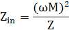
여기서, M은 피딩부(1640)와 공진기(1650) 사이의 상호 인덕턴스를 의미하고, ω 는 피딩부(1640)와 공진기(1650) 간의 공진 주파수를 의미하고, Z는 공진기(1650)에서 타겟 디바이스 측을 바라볼 때 보이는 임피던스를 의미한다. Zin은 상호 인덕턴스 M에 비례한다. 따라서, 피딩부(1640)와 공진기(1650) 사이에 상호 인덕턴스를 조절함으로써 Zin을 제어할 수 있다. 상호 인덕턴스 M은 피딩부(1640)와 공진기(1650) 사이 영역의 면적에 따라 조절될 수 있다. 피딩부(1640)의 크기에 따라 피딩부(1640)와 공진기(1650) 사이 영역의 면적이 조절될 수 있다. Zin은 피딩부(1640)의 크기에 따라 결정될 수 있으므로, 전력 증폭기의 출력 임피던스와 임피던스 매칭을 수행하기 위해 별도의 매칭 네트워크가 필요하지 않다. Here, M means mutual inductance between the
무선 전력 수신 장치에 포함된 타겟 공진기 및 피딩부도 위와 같은 자기장의 분포를 가질 수 있다. 타겟 공진기는 소스 공진기로부터 마그네틱 커플링을 통하여 무선 전력을 수신한다. 이때 수신되는 무선 전력을 통하여 타겟 공진기에서는 유도 전류가 생성될 수 있다. 타겟 공진기에서 유도 전류에 의해 발생한 자기장은 피딩부에 다시 유도 전류를 생성할 수 있다. 이때, (a)의 구조와 같이 타겟 공진기와 피딩부가 연결되면, 타겟 공진기에서 흐르는 전류의 방향과 피딩부에서 흐르는 전류의 방향은 동일해진다. 따라서, 피딩부의 내부에서는 자기장의 세기가 강화되고, 피딩부와 타겟 공진기 사이의 영역에서는 자기장의 세기가 약화될 수 있다.
The target resonator and the feeding unit included in the wireless power receiver may also have a distribution of magnetic fields as described above. The target resonator receives wireless power through the magnetic coupling from the source resonator. In this case, an induced current may be generated in the target resonator through the received wireless power. The magnetic field generated by the induced current in the target resonator may generate the induced current again in the feeding unit. At this time, when the target resonator and the feeding unit are connected as in the structure of (a), the direction of the current flowing through the target resonator and the direction of the current flowing through the feeding unit become the same. Therefore, the strength of the magnetic field may be enhanced inside the feeding part, and the strength of the magnetic field may be weakened in the region between the feeding part and the target resonator.
도 17은 일 실시예에 따른 무선 전력 전송 시스템에서 통신 장치의 블록도이다.17 is a block diagram of a communication device in a wireless power transfer system according to an embodiment.
도 17에 도시된 예는, 도 1, 도 5 및 도 6에 도시된 소스 디바이스 또는 타겟 디바이스에서 통신 기능 및 제어 기능을 수행하는 장치를 나타낸다. The example illustrated in FIG. 17 illustrates an apparatus that performs a communication function and a control function in the source device or the target device illustrated in FIGS. 1, 5, and 6.
도 17을 참조하면, 무선 전력 전송 시스템에서 통신 장치는 동작모드 변환부(1710), 측정부(1720), 결정부(1730), 제어부(1740), 전송부(1750) 및 수신부(1760)를 포함한다. Referring to FIG. 17, in the wireless power transmission system, a communication device includes an
동작모드 변환부(1710)는 통신 장치의 동작 모드를 수신 모드 또는 전송 모드로 변환할 수 있다. 통신 장치는 할당 받은 채널을 통하여 전송 모드에서 통신 장치가 무선으로 전력을 전송할 수 있는 전력 셀의 타겟과 통신을 할 수 있다. 또한, 통신 장치는 할당 받은 채널을 점유하고 있음을 일정한 세기의 신호를 이용하여, 전송 모드에서 지속적으로 전송할 수 있다. 통신 장치는 수신 모드에서 전력 셀의 타겟으로부터 정보를 수신할 수 있다. 또한, 주변 소스들로부터 채널의 할당을 요청하는 메시지를 수신할 수도 있다. 또한, 주변 소스들로부터의 간섭 신호, 기타 주변 환경의 변화 등을 고려한 채널의 상태 정보를 측정할 수도 있다.The
측정부(1720)는 통신 장치가 수신 모드로 동작하는 동안, 점유하고 있는 채널의 상태를 측정할 수 있다. 예를 들면, 채널의 수신신호 강도(RSSI, Received Signal Strength Indication) 및 링크 품질(LQI, Link Quality Indicator)을 측정할 수 있다. 채널의 수신신호 강도는 소스와 동일한 종류 또는 상이한 종류의 통신 장치들로부터 영향을 받는 무선 신호의 세기를 의미하고, 링크 품질은 점유하고 있는 채널의 통신 상태의 품질을 의미한다.The
전송부(1750)는 통신 장치가 전송 모드로 동작하는 동안, 통신 장치가 타겟과 통신을 수행하는 것과 관계없이, 할당된 채널을 점유하고 있다는 신호를 전송할 수 있다. 또한, 전송부(1750)는 점유한 채널의 상태에 관한 정보를 전송할 수 있다. 전송부(1750)는 전송 모드에서 일정한 세기의 신호(CW, constant wave)를 전송함으로써, 할당된 채널을 점유하고 있음을 주변 소스들에게 알릴 수 있다. 이때, 일정한 세기의 신호는 일정한 세기로 변조된 신호일 수도 있다. 점유한 채널의 상태에 관한 정보는 채널을 현재 점유하고 있는 소스에 관한 정보, 상기 소스로부터 전력을 수신하는 타겟에 관한 정보 및 상기 소스의 채널 사용 스케쥴에 대한 정보를 포함할 수 있다. 예를 들면, 채널을 현재 점유하고 있는 소스에 관한 정보는 소스의 ID, 소스가 점유하고 있는 채널의 식별번호 등을 포함할 수 있다.The
전송부(1750)는 주파수 합성부(1751) 및 PA(1753)를 포함할 수 있다. 주파수 합성부(1751)는 통신에 이용할 주파수를 합성할 수 있다. 주파수 합성부(1751)는 발진기(oscillator)로부터 통신에 이용할 주파수를 합성할 수 있다. PA(Power Amplifer)(1753)는 무선 주파수 대역에서 노이즈의 영향을 감소시키기 위해 신호의 전력을 증폭시킨다. 증폭된 신호는 안테나(1780)를 통하여 전송될 수 있다. 통신에 이용하는 주파수가 변경되는 경우, 변경된 주파수에 대한 정보에 기초하여 LO Generator(Local Oscillator Generator)(1770)는 변경된 주파수를 수신부(1760)에 제공할 수 있다. 제어부(1740)는 PA(1753)의 power를 조절할 수 있다.The
수신부(1760)는 통신 장치가 수신 모드로 동작하는 동안, 주변의 소스들로부터 채널 할당 요청 메시지를 수신할 수 있다. 주변의 소스들에는 통신 셀에서 이미 할당 가능한 채널을 모두 할당한 후, 진입한 추가 소스도 포함될 수 있다. 추가 소스는 통신 셀에서 각각의 채널의 상태 정보를 측정하여, 판단한 결과 최적의 채널을 선택하여 채널 할당 요청 메시지를 전송할 수 있다. 추가 소스는 채널 선택에 있어서, CW신호를 수신하는 채널의 경우는 상기 채널을 제외한다. 또한, 주변의 소스들에는 통신 셀에서 이미 채널을 할당 받은 후, 채널을 변경하려는 소스도 포함될 수 있다. The
수신부(1760)는 LNA(1761), Mixer(1763), LPF(1765), VGA(1767) 및 RX ADC(1769)를 포함할 수 있다. LNA(Low Noise Amplifier)(1761)는 안테나(1780)에서 수신한 신호를 증폭시킨다. 이때, LNA(1761)는 전송선로의 감쇠를 줄이기 위해 안테나(1780) 가까이에 위치할 수 있다. 또한, LNA(1761)는 신호에 포함된 노이즈를 감소시킬 수 있다. Mixer(1763)는 입력되는 2가지 이상의 신호를 이용하여 새로운 주파수의 신호를 생성할 수 있다. Mixer(1763)는 LNA(1761)로부터 증폭된 신호와 LO Generator(Local Oscillator Generator)(1770)로부터 제공되는 신호를 합성하여 새로운 주파수 대역의 신호를 생성한다. Mixer(1763)는 무선 주파수 대역 신호에서 기저대역 신호로 주파수를 하향할 수도 있다. LPF(Low Pass Filter)(1765)는 새로운 주파수 대역의 신호 중에서 낮은 주파수의 신호를 통과시키고, cutoff frequency보다 높은 주파수는 감쇠시킨다. VGA(Variable gain amplifier)(1767)는 LPF(1765)를 통과한 신호의 크기를 증폭시킨다. VGA(Variable gain amplifier)(1767)는 control voltage에 따라 VGA(1767)의 이득을 다르게 할 수 있다. RX ADC(Analog-Digital Converter)(1769)는 아날로그 신호를 디지털 신호로 변환한다. RX ADC(1769)는 디지털 신호를 제어부(1740)에 제공할 수 있다. 제어부(1740)는 디지털 신호를 해석하여 메시지를 복원할 수 있다. 제어부(1740)는 LNA(1761), Mixer(1763) 및 VGA(1767)의 gain을 조절할 수 있다.The
결정부(1730)는 채널 할당 요청 메시지에 대응하여, 채널 할당 여부를 결정할 수 있다. 결정부(1730)는 통신 장치의 채널 사용 스케쥴, 점유한 채널의 상태 정보에 기초하여 채널 할당 여부를 결정할 수 있다. 채널 할당이 결정되면, 전송부(1750)는 채널 할당 승인 메시지를 전송할 수 있다. 채널 할당을 하지 않는 것으로 결정되면, 전송부(1750)는 채널 할당 비승인 메시지를 전송할 수 있다. 또한, 결정부(1730)는 측정부(1720)에서 측정된 채널의 상태정보에 기초하여 점유하는 채널의 변경여부를 결정할 수 있다. 이때, 결정부(1730)는 채널의 수신신호 강도에 기초하여 채널 변경여부를 결정할 수 있다. 또는 결정부(1730)는 채널의 링크 품질에 기초하여 채널 변경여부를 결정할 수 있다.The
제어부(1740)는 CW 신호의 세기를 조절할 수 있다. 즉, 제어부(1740)는 일정한 세기로 전송되는 CW 신호의 레벨을 다양하게 할 수 있다. CW 신호의 전송을 통해 채널을 통신 장치가 사용하고 있음을 주변 소스에 알릴 수 있고, 이때, CW 신호의 레벨에 따라 채널 점유에 대한 정보를 전송할 수 있는 거리가 결정될 수 있다. 예를 들면, 통신 장치는 CW 신호의 세기가 큰 경우, CW 신호의 세기가 작은 경우보다 채널 점유에 대한 정보를 멀리 전송할 수 있다. 제어부(1740)는 주변 소스와의 거리를 고려하여, 주변 소스에 미치는 간섭을 최소화하기 위해 CW신호의 세기를 조절할 수도 있다.The
제어부(1740)는 통신 장치의 전반적인 제어를 담당하고, 동작모드 변환부(1710), 측정부(1720), 결정부(1730), 전송부(1750) 및 수신부(1760)의 기능을 수행할 수 있다. 도 17의 실시 예에서 이를 별도로 구성하여 도시한 것은 각 기능들을 구별하여 설명하기 위함이다. 따라서 실제로 제품을 구현하는 경우에 이들 모두를 제어부(1740)에서 처리하도록 구성할 수도 있으며, 이들 중 일부만을 제어부(1740)에서 처리하도록 구성할 수도 있다.
The
도 18은 다른 다른 일 실시예에 따른 무선 전력 전송 시스템에서 통신 장치의 블록도이다.18 is a block diagram of a communication device in a wireless power transfer system according to another exemplary embodiment.
도 18에 도시된 예는, 도 1, 도 5 및 도 6에 도시된 소스 디바이스 또는 타겟 디바이스에서 통신 기능 및 제어 기능을 수행하는 장치를 나타낸다.The example illustrated in FIG. 18 illustrates an apparatus for performing a communication function and a control function in the source device or the target device shown in FIGS. 1, 5, and 6.
도 18을 참조하면, 무선 전력 전송 시스템에서 통신 장치는 상태정보 검출부(1810), 식별부(1820), 결정부(1830), 제어부(1840), 전송부(1850) 및 수신부(1860)를 포함한다.Referring to FIG. 18, a communication apparatus in a wireless power transmission system includes a
상태정보 검출부(1810)는 통신 셀에 할당된 채널들의 상태정보를 검출할 수 있다. 상태정보 검출부(1810)는 상기 채널들의 수신신호 강도 및 링크 품질을 검출할 수 있다. The
식별부(1820)는 검출된 상태 정보에 기초하여 채널을 점유하고 있는 소스가 전송 모드로 동작하는지 여부를 식별할 수 있다. 식별부(1820)는 채널이 할당된 복수의 소스들 중에서 어느 소스들이 전송 모드로 동작하는지 식별할 수 있다. 이때, 식별부(1820)는 채널에서 검출된 수신신호 강도가 소정의 레벨 이상 값을 가지면, 해당 채널을 소스가 점유하고 있다고 식별할 수 있다. 또한, 식별부(1820)는 채널에서 검출된 링크 품질이 소정의 레벨 이하의 값을 가지면, 해당 채널을 소스가 점유하고 있다고 식별할 수도 있다. 또한, 식별부(1820)는 수신신호 강도 및 링크 품질을 고려하여 채널을 소스가 점유하고 있는지 여부를 식별할 수 있다. 또한, 식별부(1820)는 채널에서 일정한 세기의 신호(CW, constant wave)가 검출되면 소스가 채널을 점유하는 것으로 식별할 수도 있다. 통신 셀에 추가적으로 진입한 소스가 기존의 소스들과는 다른 종류의 소스인 경우에도, 일정한 세기의 신호를 통하여 점유 채널에 대한 정보를 획득함으로써, 점유 채널에 영향을 미치지 않을 수 있다. The
결정부(1830)는 검출된 상태 정보에 기초하여 채널 할당을 요청할 채널을 결정할 수 있다. 결정부(1830)는 채널의 수신신호 강도 또는 링크 품질에 기초하여 채널할당을 요청할 채널을 결정할 수 있다. 예를 들면, 결정부(1830)는 수신신호 강도가 낮고 링크 품질이 좋은 채널 중에서, 다른 소스에 의해 점유되지 않은 채널을 채널 할당을 요청할 채널로 결정할 수 있다. 다른 소스에 의해 점유되지 않은 채널은 식별부(1820)에서 식별될 수 있다. 이러한 결정과정에서 다른 소스에 의해 점유되지 않은 채널은 채널 할당 요청에서 제외되므로, 채널 할당 요청으로 인하여 채널에 발생하는 간섭을 줄일 수 있다. 또한, 점유된 채널에서는 타겟과 소스간에 안정적으로 통신을 수행할 수 있다.The
전송부(1850)는 결정부(1830)에서 결정된 채널을 할당 받기 위해, 결정된 채널을 이미 할당 받았던 소스에게 채널 할당 요청 메시지를 전송할 수 있다. 보다 구체적으로 전송부(1850)는 결정된 채널에서 수신 모드로 동작하고 있는 소스에게 채널 할당 요청 메시지를 전송할 수 있다. 또한, 통신 셀에 위치한 동일한 종류의 소스 간에는 소스의 전송 모드 및 수신 모드의 타이밍이 동일하게 설정될 수 있다. 따라서, 전송부(1850)는 결정된 채널을 이미 할당 받았던 소스가 수신 모드로 동작하는 타이밍에, 채널 할당 요청 메시지를 전송할 수 있다. 즉, 채널 할당을 요청할 채널이 결정되었다면, 전송부(1850)는 점유 채널의 소스가 수신 모드로 동작하는 타이밍이 될때까지 대기한 후, 채널 할당 요청 메시지를 전송할 수도 있다.The
전송부(1850)는 주파수 합성부(1851) 및 PA(1853)를 포함할 수 있다. 주파수 합성부(1851)는 통신에 이용할 주파수를 합성할 수 있다. 주파수 합성부(1851)는 발진기(oscillator)로부터 통신에 이용할 주파수를 합성할 수 있다. PA(Power Amplifer)(1853)는 무선 주파수 대역에서 노이즈의 영향을 감소시키기 위해 신호의 전력을 증폭시킨다. 증폭된 신호는 안테나(1880)를 통하여 전송될 수 있다. 통신에 이용하는 주파수가 변경되는 경우, 변경된 주파수에 대한 정보에 기초하여 LO Generator(Local Oscillator Generator)(1870)는 변경된 주파수를 수신부(1860)에 제공할 수 있다. 제어부(1840)는 PA(1853)의 power를 조절할 수 있다.The
수신부(1860)는 채널 할당 승인 메시지 또는 채널 할당 비승인 메시지를 수신할 수 있다. 채널 할당 요청 메시지에 대응하여, 이미 채널을 할당 받았던 소스가 상기 소스의 상황 및 채널의 상태에 따라 채널 할당의 승인여부를 결정할 수 있다. 채널 할당의 승인여부에 따라 이미 채널을 할당 받았던 소스로부터 채널 할당 승인 메시지 또는 채널 할당 비승인 메시지가 전송될 수 있다. The
채널 할당 비승인 메시지를 수신하는 경우, 통신 장치는 다른 채널들의 상태정보를 다시 검출하고, 전송 모드로 동작하지 않는 소스들에게 다시 채널 할당을 요청할 수 있다. 또는 통신 장치는 상태정보가 가장 좋은 채널의 소스가 수신 모드로 동작할 때까지 대기한 후, 채널 할당을 요청할 수도 있다. When receiving the channel assignment disapproval message, the communication device may detect the status information of other channels again, and request channel assignment again from sources not operating in the transmission mode. Alternatively, the communication device may wait until the source of the channel having the best status information operates in the reception mode, and then request channel allocation.
수신부(1860)는 LNA(1861), Mixer(1863), LPF(1865), VGA(1867) 및 RX ADC(1869)를 포함할 수 있다. LNA(Low Noise Amplifier)(1861)는 안테나(1880)에서 수신한 신호를 증폭시킨다. 이때, LNA(1861)는 전송선로의 감쇠를 줄이기 위해 안테나(1880) 가까이에 위치할 수 있다. 또한, LNA(1861)는 신호에 포함된 노이즈를 감소시킬 수 있다. Mixer(1863)는 입력되는 2가지 이상의 신호를 이용하여 새로운 주파수의 신호를 생성할 수 있다. Mixer(1863)는 LNA(1861)로부터 증폭된 신호와 LO Generator(Local Oscillator Generator)(1870)로부터 제공되는 신호를 합성하여 새로운 주파수 대역의 신호를 생성한다. Mixer(1863)는 무선 주파수 대역 신호에서 기저대역 신호로 주파수를 하향할 수도 있다. LPF(Low Pass Filter)(1865)는 새로운 주파수 대역의 신호 중에서 낮은 주파수의 신호를 통과시키고, cutoff frequency보다 높은 주파수는 감쇠시킨다. VGA(Variable gain amplifier)(1867)는 LPF(1865)를 통과한 신호의 크기를 증폭시킨다. VGA(Variable gain amplifier)(1867)는 control voltage에 따라 VGA(1867)의 이득을 다르게 할 수 있다. RX ADC(Analog-Digital Converter)(1869)는 아날로그 신호를 디지털 신호로 변환한다. RX ADC(1869)는 디지털 신호를 제어부(1840)에 제공할 수 있다. 제어부(1840)는 디지털 신호를 해석하여 메시지를 복원할 수 있다. 제어부(1840)는 LNA(1861), Mixer(1863) 및 VGA(1867)의 gain을 조절할 수 있다.The
제어부(1840)는 통신 장치의 전반적인 제어를 담당하고, 상태정보 검출부(1810), 식별부(1820), 결정부(1830), 전송부(1850) 및 수신부(1860)의 기능을 수행할 수 있다. 도 18의 실시 예에서 이를 별도로 구성하여 도시한 것은 각 기능들을 구별하여 설명하기 위함이다. 따라서 실제로 제품을 구현하는 경우에 이들 모두를 제어부(1840)에서 처리하도록 구성할 수도 있으며, 이들 중 일부만을 제어부(1840)에서 처리하도록 구성할 수도 있다.
The
도 19는 일 실시예에 따른 전기 자동차(electric vehicle) 충전 시스템을 나타낸다. 19 illustrates an electric vehicle charging system according to one embodiment.
도 19를 참조하면, 전기 자동차 충전 시스템(1900)은 소스 시스템(1910), 소스 공진기(1920), 타겟 공진기(1930), 타겟 시스템(1940) 및 전기 자동차용 배터리(1950)을 포함한다. Referring to FIG. 19, an electric
전기 자동차 충전 시스템(1900)은 도 1의 무선 전력 전송 시스템과 유사한 구조를 가진다. 즉, 전기 자동차 충전 시스템(1900)은 소스 시스템(1910) 및 소스 공진기(1920)로 구성되는 소스를 포함한다. 또한, 전기 자동차 충전 시스템(1900)은 타겟 공진기(1930) 및 타겟 시스템(1940)로 구성되는 타겟을 포함한다. The electric
이때, 소스 시스템(1910)은 도 1의 소스(110)와 같이, Variable SMPS, Power Amplifier, 매칭 네트워크, 제어부 및 통신부를 포함할 수 있다. 이때, 타겟 시스템(1940)은 도 1의 타겟(120)과 같이, 매칭 네트워크, 정류부, DC/DC 컨버터, 통신부 및 제어부를 포함할 수 있다. In this case, the
전기 자동차용 배터리(1950)는 타겟 시스템(1940)에 의해 충전 될 수 있다. The
전기 자동차 충전 시스템(1900)은 수 KHz~수십 MHz의 공진 주파수를 사용할 수 있다. The electric
소스 시스템(1910)은 충전 차량의 종류, 배터리의 용량, 배터리의 충전 상태에 따라 전력을 생성하고, 생성된 전력을 타겟 시스템(1940)으로 공급할 수 있다. The
소스 시스템(1910)은 소스 공진기(1920) 및 타겟 공진기(1930)의 정렬(alignment)를 맞추기 위한 제어를 수행할 수 있다. 예를 들어, 소스 시스템(1910)의 제어부는 소스 공진기(1920)와 타겟 공진기(1930)의 alignment가 맞지 않은 경우, 타겟 시스템(1940)으로 메시지를 전송하여 alignment를 제어할 수 있다. The
이때, alignment가 맞지 않은 경우란, 타겟 공진기(1930)의 위치가 마그네틱 레조넌스(magnetic resonance)가 최대로 일어나기 위한 위치에 있지 않은 경우 일 수 있다. 즉, 차량이 정확하게 정차되지 않은 경우, 소스 시스템(1910)은 차량의 위치를 조정하도록 유도함으로써, 소스 공진기(1920)와 타겟 공진기(1930)의 alignment가 맞도록 유도할 수 있다. In this case, the misalignment may be a case where the position of the
소스 시스템(1910)과 타겟 시스템(1940)은 통신을 통해, 차량의 식별자를 송수신할 수 있고, 각종 메시지를 주고 받을 수 있다. The
도 2 내지 도 18에서 설명된 내용들은 전기 자동차 충전 시스템(1900)에 적용될 수 있다. 다만, 전기 자동차 충전 시스템(1900)은 수 KHz~수십 MHz의 공진 주파수를 사용하고, 전기 자동차용 배터리(1950)를 충전하기 위해 수십 watt이상의 전력 전송을 수행할 수 있다.
2 to 18 may be applied to the electric
본 발명의 실시 예에 따른 방법들은 다양한 컴퓨터 수단을 통하여 수행될 수 있는 프로그램 명령 형태로 구현되어 컴퓨터 판독 가능 매체에 기록될 수 있다. 상기 컴퓨터 판독 가능 매체는 프로그램 명령, 데이터 파일, 데이터 구조 등을 단독으로 또는 조합하여 포함할 수 있다. 상기 매체에 기록되는 프로그램 명령은 본 발명을 위하여 특별히 설계되고 구성된 것들이거나 컴퓨터 소프트웨어 당업자에게 공지되어 사용 가능한 것일 수도 있다. Methods according to an embodiment of the present invention can be implemented in the form of program instructions that can be executed by various computer means and recorded in a computer readable medium. The computer readable medium may include program instructions, data files, data structures, etc. alone or in combination. Program instructions recorded on the media may be those specially designed and constructed for the purposes of the present invention, or they may be of the kind well-known and available to those having skill in the computer software arts.
이상과 같이 본 발명은 비록 한정된 실시예와 도면에 의해 설명되었으나, 본 발명은 상기의 실시예에 한정되는 것은 아니며, 본 발명이 속하는 분야에서 통상의 지식을 가진 자라면 이러한 기재로부터 다양한 수정 및 변형이 가능하다.As described above, the present invention has been described by way of limited embodiments and drawings, but the present invention is not limited to the above embodiments, and those skilled in the art to which the present invention pertains various modifications and variations from such descriptions. This is possible.
그러므로, 본 발명의 범위는 설명된 실시예에 국한되어 정해져서는 아니 되며, 후술하는 특허청구범위뿐 아니라 이 특허청구범위와 균등한 것들에 의해 정해져야 한다.Therefore, the scope of the present invention should not be limited to the described embodiments, but should be determined not only by the claims below but also by the equivalents of the claims.
Claims (16)
상기 선택된 제어용 통신 채널을 통해 채널 고정 명령어 및 상기 소스 디바이스의 식별자를 포함하는 초기 제어 신호를 상기 타겟 디바이스에게 전송하는 단계;
상기 타겟 디바이스로부터 상기 채널 고정 명령어에 대한 응답 신호를 수신하는 단계; 및
상기 타겟 디바이스의 충전을 위한 충전 전력을 상기 타겟 디바이스로 전송하는 충전 모드로 진입하는 단계를 포함하고,
상기 채널 고정 명령어는 상기 선택된 제어용 통신 채널을 사용하도록 상기 타겟 디바이스에게 요청하는 명령어이고,
상기 충전 전력은 마그네틱 커플링에 의해 상기 소스 디바이스로부터 상기 타겟 디바이스로 전송되는,
무선 전력 전송 시스템에서 통신 채널 할당 및 전력 전송 방법.When a target device that receives power wirelessly from a source device is detected, a control communication for searching for an available control communication channel in an unoccupied state and performing communication with the target device based on whether a carrier signal is detected. Selecting a channel;
Transmitting an initial control signal including a channel fixed command and an identifier of the source device to the target device through the selected control communication channel;
Receiving a response signal for the channel fixation command from the target device; And
Entering a charging mode for transmitting charging power for charging the target device to the target device,
The channel fixing command is a command for requesting the target device to use the selected control communication channel,
The charging power is transmitted from the source device to the target device by magnetic coupling,
Communication channel allocation and power transmission method in a wireless power transmission system.
상기 제어용 통신 채널을 선택하는 단계는,
상기 타겟 디바이스의 통신 기능 및 제어 기능을 활성화 시키는 웨이크-업 전력을 상기 타겟 디바이스로 전송하는 단계를 포함하는,
무선 전력 전송 시스템에서 통신 채널 할당 및 전력 전송 방법.The method of claim 1,
Selecting the control communication channel,
Transmitting wake-up power to the target device to activate a communication function and a control function of the target device,
Communication channel allocation and power transmission method in a wireless power transmission system.
상기 제어용 통신 채널을 검색하는 단계는,
N개(N은 2이상의 정수) 통신 채널들 중 제1 통신 채널을 선택하는 단계;
상기 제1 통신 채널을 통해 상기 캐리어 신호가 검출되는 지를 판단하는 단계;
상기 캐리어 신호가 검출되면, 검출된 캐리어 신호의 신호 레벨이 기 설정된 값 이상인지 여부를 판단하는 단계; 및
상기 캐리어 신호의 신호 레벨이 기 설정된 값 이상이면, 상기 N개의 통신 채널들 중 제2 통신 채널을 선택하고, 상기 제2 통신 채널을 통해 상기 캐리어 신호가 검출되는 지를 판단하는 단계를 포함하는,
무선 전력 전송 시스템에서 통신 채널 할당 및 전력 전송 방법.The method of claim 2,
Searching for the control communication channel,
Selecting a first communication channel among N (N is an integer of 2 or more) communication channels;
Determining whether the carrier signal is detected over the first communication channel;
When the carrier signal is detected, determining whether a signal level of the detected carrier signal is equal to or greater than a preset value; And
If the signal level of the carrier signal is greater than or equal to a preset value, selecting a second communication channel among the N communication channels, and determining whether the carrier signal is detected through the second communication channel;
Communication channel allocation and power transmission method in a wireless power transmission system.
상기 제어용 통신 채널을 선택하는 단계는,
상기 제1 통신 채널을 통해 상기 캐리어 신호가 검출되지 않거나, 상기 제1 통신 채널을 통해 수신된 상기 캐리어 신호의 신호 레벨이 상기 기 설정된 값 보다 작으면, 상기 제1 통신 채널을 상기 제어용 통신 채널로 선택하는,
무선 전력 전송 시스템에서 통신 채널 할당 및 전력 전송 방법.The method of claim 3,
Selecting the control communication channel,
If the carrier signal is not detected through the first communication channel or the signal level of the carrier signal received through the first communication channel is smaller than the preset value, the first communication channel is converted into the control communication channel. Choosing,
Communication channel allocation and power transmission method in a wireless power transmission system.
상기 초기 제어 신호는 상기 타겟 디바이스가 상기 N개의 통신채널을 스캔하는 시간을 고려하여 연속적인 시간 동안 전송되는,
무선 전력 전송 시스템에서 통신 채널 할당 및 전력 전송 방법.The method of claim 3,
The initial control signal is transmitted for a continuous time in consideration of the time the target device scans the N communication channels,
Communication channel allocation and power transmission method in a wireless power transmission system.
상기 충전 모드에서 통신 오류가 발생하는지를 판단하는 단계;
상기 통신 오류가 발생하면, N개(N은 2이상의 정수) 통신 채널들 중 빈 채널을 검색하는 단계;
상기 선택된 제어용 통신 채널을 통해 상기 타겟 디바이스로 채널 변경 명령어를 전송하는 단계; 및
상기 채널 변경 명령어에 대한 응답을 수신하면, 상기 검색된 빈 채널로 상기 제어용 통신 채널을 변경하는 단계를 더 포함하는,
무선 전력 전송 시스템에서 통신 채널 할당 및 전력 전송 방법.The method of claim 1,
Determining whether a communication error occurs in the charging mode;
Searching for an empty channel among N communication channels (N is an integer of 2 or more) when the communication error occurs;
Transmitting a channel change command to the target device through the selected control communication channel; And
When receiving a response to the channel change command, changing the control communication channel to the found free channel;
Communication channel allocation and power transmission method in a wireless power transmission system.
상기 충전 모드에서 새로운 타겟 디바이스가 검출되면, 상기 새로운 타겟 디바이스의 디바이스 로드를 고려하여 상기 충전 전력의 레벨을 조정하는 단계;
상기 충전 전력에 대한 반사파를 검출하는 단계; 및
상기 검출된 반사파의 신호 레벨이 기 설정된 값 보다 크면, 상기 새로운 타겟 디바이스의 접속을 해제시키는 단계를 더 포함하는,
무선 전력 전송 시스템에서 통신 채널 할당 및 전력 전송 방법.The method of claim 1,
If a new target device is detected in the charging mode, adjusting the level of the charging power in consideration of the device load of the new target device;
Detecting a reflected wave with respect to the charging power; And
If the signal level of the detected reflected wave is greater than a preset value, disconnecting the new target device;
Communication channel allocation and power transmission method in a wireless power transmission system.
상기 초기 제어 신호의 수신 감도에 대한 정보 및 상기 충전 전력의 수신 레벨에 대한 정보 중 적어도 어느 하나를 수신하는 단계; 및
상기 초기 제어 신호의 수신 감도에 대한 정보 및 상기 충전 전력의 수신 레벨에 대한 정보 중 적어도 어느 하나에 기초하여 상기 타겟 디바이스가 상기 소스 디바이스의 전력 전송 영역 내에 위치하는지를 결정하는 단계를 더 포함하는,
무선 전력 전송 시스템에서 통신 채널 할당 및 전력 전송 방법.The method of claim 1,
Receiving at least one of information on a reception sensitivity of the initial control signal and information on a reception level of the charging power; And
Determining whether the target device is located in a power transmission area of the source device based on at least one of the information on the reception sensitivity of the initial control signal and the information on the reception level of the charging power.
Communication channel allocation and power transmission method in a wireless power transmission system.
상기 웨이크-업 전력을 이용하여 통신 모듈을 활성화시키는 단계;
N개(N은 2이상의 정수) 통신 채널들 중 제1 통신 채널을 선택하는 단계;
캐리어 신호의 검출 여부에 기초하여 상기 제1 통신 채널이 점유된 상태의 사용중인 채널인지를 판단하는 단계;
상기 제1 통신 채널이 점유된 상태의 사용중인 채널이면 상기 소스 디바이스로부터 채널 고정 명령어를 포함하는 초기 제어 신호가 수신되는지 여부를 판단하는 단계;
상기 초기 제어 신호가 수신되면, 상기 채널 고정 명령어에 대한 응답 신호를 상기 소스 디바이스로 전송하는 단계; 및
상기 소스 디바이스로부터 상기 타겟 디바이스의 충전을 위한 충전 전력을 수신하는 단계를 포함하고,
상기 충전 전력은 마그네틱 커플링에 의해 상기 소스 디바이스로부터 상기 타겟 디바이스로 전송되는,
무선 전력 전송 시스템에서 통신 채널 할당 및 전력 전송 방법.Receiving, by the target device, a wake-up power to activate a communication and control function from the source device;
Activating a communication module using the wake-up power;
Selecting a first communication channel among N (N is an integer of 2 or more) communication channels;
Determining whether the first communication channel is in use in an occupied state based on whether a carrier signal is detected;
Determining whether an initial control signal including a channel fix command is received from the source device if the first communication channel is in use in an occupied state;
If the initial control signal is received, transmitting a response signal to the source device to the source device; And
Receiving charging power for charging the target device from the source device,
The charging power is transmitted from the source device to the target device by magnetic coupling,
Communication channel allocation and power transmission method in a wireless power transmission system.
상기 제1 통신 채널이 사용중인 채널이 아니면, 상기 N개의 통신 채널들 중 제2 통신 채널을 선택하고 상기 제2 통신 채널이 사용중인 채널인지를 판단하는 단계를 더 포함하는,
무선 전력 전송 시스템에서 통신 채널 할당 및 전력 전송 방법.The method of claim 9,
If the first communication channel is not a busy channel, selecting a second communication channel among the N communication channels and determining whether the second communication channel is a busy channel;
Communication channel allocation and power transmission method in a wireless power transmission system.
상기 초기 제어 신호의 수신 감도에 대한 정보 및 상기 충전 전력의 수신 레벨에 대한 정보 중 적어도 어느 하나를 상기 소스 디바이스로 전송하는 단계; 및
상기 초기 제어 신호의 수신 감도에 대한 정보 및 상기 충전 전력의 수신 레벨에 대한 정보 중 적어도 어느 하나에 기초하여 상기 소스 디바이스로부터 제어 ID를 할당 받는 단계를 포함하는,
무선 전력 전송 시스템에서 통신 채널 할당 및 전력 전송 방법.The method of claim 9,
Transmitting at least one of information on a reception sensitivity of the initial control signal and information on a reception level of the charging power to the source device; And
And assigning a control ID from the source device based on at least one of the information on the reception sensitivity of the initial control signal and the information on the reception level of the charging power.
Communication channel allocation and power transmission method in a wireless power transmission system.
마그네틱 커플링을 통해 상기 웨이크-업(wake-up) 전력 또는 충전 전력을 타겟 디바이스에 전송하는 소스 공진기; 및
상기 타겟 디바이스와 통신을 수행하기 위한 제어용 통신 채널을 선택하는 제어 및 통신부를 포함하고,
상기 제어 및 통신부는,
소스 디바이스로부터 무선으로 전력을 수신하는 타겟 디바이스가 검출되면, 캐리어(carrier) 신호의 검출 여부에 기초하여 점유되지 않은 상태의 사용 가능한 제어용 통신 채널을 검색하여 상기 타겟 디바이스와 통신을 수행하기 위한 제어용 통신 채널을 선택하고, 상기 선택된 제어용 통신 채널을 통해 채널 고정 명령어 및 상기 소스 디바이스의 식별자를 포함하는 초기 제어 신호를 상기 타겟 디바이스에게 전송하고, 상기 타겟 디바이스로부터 상기 채널 고정 명령어에 대한 응답 신호를 수신하고, 상기 타겟 디바이스의 충전을 위한 충전 전력을 상기 타겟 디바이스로 전송하는 충전 모드로 진입하고,
상기 채널 고정 명령어는 상기 선택된 제어용 통신 채널을 사용하도록 상기 타겟 디바이스에게 요청하는 명령어이고,
상기 충전 전력은 마그네틱 커플링에 의해 상기 소스 디바이스로부터 상기 타겟 디바이스로 전송되는,
무선 전력 전송 시스템의 소스 디바이스.A power conversion unit converting a DC voltage into an AC voltage using a resonance frequency to generate wake-up power or charging power;
A source resonator for transmitting the wake-up power or charging power to a target device via magnetic coupling; And
A control and communication unit for selecting a control communication channel for performing communication with the target device,
The control and communication unit,
When a target device that receives power wirelessly from a source device is detected, a control communication for searching for an available control communication channel in an unoccupied state and performing communication with the target device based on whether a carrier signal is detected. Select a channel, transmit an initial control signal including a channel fixed command and an identifier of the source device to the target device through the selected control communication channel, receive a response signal for the channel fixed command from the target device; Enters a charging mode for transmitting charging power for charging the target device to the target device,
The channel fixing command is a command for requesting the target device to use the selected control communication channel,
The charging power is transmitted from the source device to the target device by magnetic coupling,
Source device of a wireless power transfer system.
상기 제어 및 통신부는,
N개(N은 2이상의 정수) 통신 채널들 중 제1 통신 채널을 선택하고, 상기 제1 통신 채널을 통해 상기 캐리어 신호가 검출되는 지를 판단하고, 상기 캐리어 신호가 검출되면, 검출된 캐리어 신호의 신호 레벨이 기 설정된 값 이상인지 여부를 판단하고, 상기 캐리어 신호의 신호 레벨이 기 설정된 값 이상이면, 상기 N개의 통신 채널들 중 제2 통신 채널을 선택하고, 상기 제2 통신 채널을 통해 상기 캐리어 신호가 검출되는 지를 판단하는,
무선 전력 전송 시스템의 소스 디바이스.The method of claim 13,
The control and communication unit,
Select a first communication channel among N communication channels (N is an integer of 2 or more), determine whether the carrier signal is detected through the first communication channel, and when the carrier signal is detected, It is determined whether a signal level is greater than or equal to a preset value, and if a signal level of the carrier signal is greater than or equal to a preset value, a second communication channel is selected from the N communication channels, and the carrier is transmitted through the second communication channel. To determine if a signal is detected,
Source device of a wireless power transfer system.
상기 웨이크-업 전력에 의해 활성화되고, N개(N은 2이상의 정수) 통신 채널들 중 제1 통신 채널을 선택하는 제어 및 통신부를 포함하고,
상기 제어 및 통신부는,
상기 웨이크-업 전력을 수신하고, 상기 웨이크-업 전력을 이용하여 통신 모듈을 활성화시키고, N개(N은 2이상의 정수) 통신 채널들 중 제1 통신 채널을 선택하고, 캐리어 신호의 검출 여부에 기초하여 상기 제1 통신 채널이 점유된 상태의 사용중인 채널인지를 판단하고, 상기 제1 통신 채널이 사용중인 채널이면 상기 소스 디바이스로부터 채널 고정 명령어를 포함하는 초기 제어 신호가 수신되는지 여부를 판단하고, 상기 초기 제어 신호가 수신되면, 상기 채널 고정 명령어에 대한 응답 신호를 상기 소스 디바이스로 전송하는,
무선 전력 전송 시스템의 타겟 디바이스.A target resonator receiving, via magnetic coupling, wake-up power or charging power for charging to activate a communication and control function from a source device; And
A control and communication unit activated by the wake-up power and selecting a first communication channel among N (N is an integer of 2 or more) communication channels,
The control and communication unit,
Receiving the wake-up power, activating a communication module using the wake-up power, selecting a first communication channel among N (N is an integer of 2 or more), and detecting whether a carrier signal is detected. Determine whether the first communication channel is an active channel in an occupied state; if the first communication channel is an active channel, determine whether an initial control signal including a channel fixing command is received from the source device; When the initial control signal is received, transmitting a response signal to the source device to the source device,
Target device of a wireless power transfer system.
상기 제어 및 통신부는,
상기 제1 통신 채널을 통해 상기 캐리어 신호가 검출되지 않으면, 상기 N개의 통신 채널들 중 제2 통신 채널을 선택하고 상기 제2 통신 채널을 통해 상기 캐리어 신호가 검출되는 지를 판단하는,
무선 전력 전송 시스템의 타겟 디바이스.The method of claim 15,
The control and communication unit,
If the carrier signal is not detected through the first communication channel, selecting a second communication channel among the N communication channels and determining whether the carrier signal is detected through the second communication channel;
Target device of a wireless power transfer system.
Priority Applications (2)
| Application Number | Priority Date | Filing Date | Title |
|---|---|---|---|
| PCT/KR2012/006089 WO2013022207A1 (en) | 2011-08-05 | 2012-07-31 | Wireless power transmission system, and method and apparatus for allocating communication channel and transmitting power in wireless power transmission system |
| EP12822882.2A EP2740223A4 (en) | 2011-08-05 | 2012-07-31 | WIRELESS POWER TRANSMISSION SYSTEM, AND METHOD AND APPARATUS FOR ALLOCATING A COMMUNICATION CHANNEL AND TRANSMITTING POWER IN A WIRELESS POWER TRANSMISSION SYSTEM |
Applications Claiming Priority (4)
| Application Number | Priority Date | Filing Date | Title |
|---|---|---|---|
| US201161491953P | 2011-06-01 | 2011-06-01 | |
| US61/491,953 | 2011-06-01 | ||
| KR1020110078104 | 2011-08-05 | ||
| KR20110078104 | 2011-08-05 |
Publications (2)
| Publication Number | Publication Date |
|---|---|
| KR20120135077A KR20120135077A (en) | 2012-12-12 |
| KR102040712B1 true KR102040712B1 (en) | 2019-11-27 |
Family
ID=47903121
Family Applications (1)
| Application Number | Title | Priority Date | Filing Date |
|---|---|---|---|
| KR1020120058369A Active KR102040712B1 (en) | 2011-06-01 | 2012-05-31 | Wireless power transmission system, method and apparatus for communication channel allocation and power transmission in wireless power transmission system |
Country Status (2)
| Country | Link |
|---|---|
| US (1) | US9142997B2 (en) |
| KR (1) | KR102040712B1 (en) |
Families Citing this family (223)
| Publication number | Priority date | Publication date | Assignee | Title |
|---|---|---|---|---|
| US20130058379A1 (en) * | 2011-09-05 | 2013-03-07 | Samsung Electronics Co., Ltd. | Communication apparatus and communication method in wireless power transmission system |
| US9054547B2 (en) * | 2011-09-06 | 2015-06-09 | Samsung Electronics Co., Ltd | Communication method and apparatus in wireless recharging system |
| US10243414B1 (en) | 2014-05-07 | 2019-03-26 | Energous Corporation | Wearable device with wireless power and payload receiver |
| US10223717B1 (en) | 2014-05-23 | 2019-03-05 | Energous Corporation | Systems and methods for payment-based authorization of wireless power transmission service |
| US9838083B2 (en) | 2014-07-21 | 2017-12-05 | Energous Corporation | Systems and methods for communication with remote management systems |
| US9831718B2 (en) | 2013-07-25 | 2017-11-28 | Energous Corporation | TV with integrated wireless power transmitter |
| US10063064B1 (en) | 2014-05-23 | 2018-08-28 | Energous Corporation | System and method for generating a power receiver identifier in a wireless power network |
| US9853692B1 (en) | 2014-05-23 | 2017-12-26 | Energous Corporation | Systems and methods for wireless power transmission |
| US9893555B1 (en) | 2013-10-10 | 2018-02-13 | Energous Corporation | Wireless charging of tools using a toolbox transmitter |
| US10312715B2 (en) | 2015-09-16 | 2019-06-04 | Energous Corporation | Systems and methods for wireless power charging |
| US9859756B2 (en) | 2012-07-06 | 2018-01-02 | Energous Corporation | Transmittersand methods for adjusting wireless power transmission based on information from receivers |
| US10148097B1 (en) | 2013-11-08 | 2018-12-04 | Energous Corporation | Systems and methods for using a predetermined number of communication channels of a wireless power transmitter to communicate with different wireless power receivers |
| US20140008993A1 (en) | 2012-07-06 | 2014-01-09 | DvineWave Inc. | Methodology for pocket-forming |
| US10224758B2 (en) | 2013-05-10 | 2019-03-05 | Energous Corporation | Wireless powering of electronic devices with selective delivery range |
| US9824815B2 (en) | 2013-05-10 | 2017-11-21 | Energous Corporation | Wireless charging and powering of healthcare gadgets and sensors |
| US9899873B2 (en) | 2014-05-23 | 2018-02-20 | Energous Corporation | System and method for generating a power receiver identifier in a wireless power network |
| US9954374B1 (en) | 2014-05-23 | 2018-04-24 | Energous Corporation | System and method for self-system analysis for detecting a fault in a wireless power transmission Network |
| US9853458B1 (en) | 2014-05-07 | 2017-12-26 | Energous Corporation | Systems and methods for device and power receiver pairing |
| US10992185B2 (en) | 2012-07-06 | 2021-04-27 | Energous Corporation | Systems and methods of using electromagnetic waves to wirelessly deliver power to game controllers |
| US10211680B2 (en) | 2013-07-19 | 2019-02-19 | Energous Corporation | Method for 3 dimensional pocket-forming |
| US10230266B1 (en) | 2014-02-06 | 2019-03-12 | Energous Corporation | Wireless power receivers that communicate status data indicating wireless power transmission effectiveness with a transmitter using a built-in communications component of a mobile device, and methods of use thereof |
| US10270261B2 (en) | 2015-09-16 | 2019-04-23 | Energous Corporation | Systems and methods of object detection in wireless power charging systems |
| US10965164B2 (en) | 2012-07-06 | 2021-03-30 | Energous Corporation | Systems and methods of wirelessly delivering power to a receiver device |
| US9973021B2 (en) | 2012-07-06 | 2018-05-15 | Energous Corporation | Receivers for wireless power transmission |
| US9887739B2 (en) | 2012-07-06 | 2018-02-06 | Energous Corporation | Systems and methods for wireless power transmission by comparing voltage levels associated with power waves transmitted by antennas of a plurality of antennas of a transmitter to determine appropriate phase adjustments for the power waves |
| US10211682B2 (en) | 2014-05-07 | 2019-02-19 | Energous Corporation | Systems and methods for controlling operation of a transmitter of a wireless power network based on user instructions received from an authenticated computing device powered or charged by a receiver of the wireless power network |
| US10050462B1 (en) | 2013-08-06 | 2018-08-14 | Energous Corporation | Social power sharing for mobile devices based on pocket-forming |
| US9893554B2 (en) | 2014-07-14 | 2018-02-13 | Energous Corporation | System and method for providing health safety in a wireless power transmission system |
| US10128693B2 (en) | 2014-07-14 | 2018-11-13 | Energous Corporation | System and method for providing health safety in a wireless power transmission system |
| US9812890B1 (en) | 2013-07-11 | 2017-11-07 | Energous Corporation | Portable wireless charging pad |
| US9882427B2 (en) | 2013-05-10 | 2018-01-30 | Energous Corporation | Wireless power delivery using a base station to control operations of a plurality of wireless power transmitters |
| US10141768B2 (en) | 2013-06-03 | 2018-11-27 | Energous Corporation | Systems and methods for maximizing wireless power transfer efficiency by instructing a user to change a receiver device's position |
| US10199835B2 (en) | 2015-12-29 | 2019-02-05 | Energous Corporation | Radar motion detection using stepped frequency in wireless power transmission system |
| US9991741B1 (en) | 2014-07-14 | 2018-06-05 | Energous Corporation | System for tracking and reporting status and usage information in a wireless power management system |
| US10063105B2 (en) | 2013-07-11 | 2018-08-28 | Energous Corporation | Proximity transmitters for wireless power charging systems |
| US10992187B2 (en) | 2012-07-06 | 2021-04-27 | Energous Corporation | System and methods of using electromagnetic waves to wirelessly deliver power to electronic devices |
| US10291055B1 (en) | 2014-12-29 | 2019-05-14 | Energous Corporation | Systems and methods for controlling far-field wireless power transmission based on battery power levels of a receiving device |
| US10256657B2 (en) | 2015-12-24 | 2019-04-09 | Energous Corporation | Antenna having coaxial structure for near field wireless power charging |
| US10193396B1 (en) | 2014-05-07 | 2019-01-29 | Energous Corporation | Cluster management of transmitters in a wireless power transmission system |
| US10381880B2 (en) | 2014-07-21 | 2019-08-13 | Energous Corporation | Integrated antenna structure arrays for wireless power transmission |
| US9368020B1 (en) | 2013-05-10 | 2016-06-14 | Energous Corporation | Off-premises alert system and method for wireless power receivers in a wireless power network |
| US9859757B1 (en) | 2013-07-25 | 2018-01-02 | Energous Corporation | Antenna tile arrangements in electronic device enclosures |
| US9867062B1 (en) | 2014-07-21 | 2018-01-09 | Energous Corporation | System and methods for using a remote server to authorize a receiving device that has requested wireless power and to determine whether another receiving device should request wireless power in a wireless power transmission system |
| US10128699B2 (en) | 2014-07-14 | 2018-11-13 | Energous Corporation | Systems and methods of providing wireless power using receiver device sensor inputs |
| US9900057B2 (en) | 2012-07-06 | 2018-02-20 | Energous Corporation | Systems and methods for assigning groups of antenas of a wireless power transmitter to different wireless power receivers, and determining effective phases to use for wirelessly transmitting power using the assigned groups of antennas |
| US9906065B2 (en) | 2012-07-06 | 2018-02-27 | Energous Corporation | Systems and methods of transmitting power transmission waves based on signals received at first and second subsets of a transmitter's antenna array |
| US10063106B2 (en) | 2014-05-23 | 2018-08-28 | Energous Corporation | System and method for a self-system analysis in a wireless power transmission network |
| US10218227B2 (en) | 2014-05-07 | 2019-02-26 | Energous Corporation | Compact PIFA antenna |
| US9843201B1 (en) | 2012-07-06 | 2017-12-12 | Energous Corporation | Wireless power transmitter that selects antenna sets for transmitting wireless power to a receiver based on location of the receiver, and methods of use thereof |
| US10008889B2 (en) | 2014-08-21 | 2018-06-26 | Energous Corporation | Method for automatically testing the operational status of a wireless power receiver in a wireless power transmission system |
| US9143000B2 (en) | 2012-07-06 | 2015-09-22 | Energous Corporation | Portable wireless charging pad |
| US10439448B2 (en) | 2014-08-21 | 2019-10-08 | Energous Corporation | Systems and methods for automatically testing the communication between wireless power transmitter and wireless power receiver |
| US9871398B1 (en) * | 2013-07-01 | 2018-01-16 | Energous Corporation | Hybrid charging method for wireless power transmission based on pocket-forming |
| US10124754B1 (en) | 2013-07-19 | 2018-11-13 | Energous Corporation | Wireless charging and powering of electronic sensors in a vehicle |
| US10038337B1 (en) | 2013-09-16 | 2018-07-31 | Energous Corporation | Wireless power supply for rescue devices |
| US9891669B2 (en) | 2014-08-21 | 2018-02-13 | Energous Corporation | Systems and methods for a configuration web service to provide configuration of a wireless power transmitter within a wireless power transmission system |
| US9941707B1 (en) | 2013-07-19 | 2018-04-10 | Energous Corporation | Home base station for multiple room coverage with multiple transmitters |
| US9847677B1 (en) | 2013-10-10 | 2017-12-19 | Energous Corporation | Wireless charging and powering of healthcare gadgets and sensors |
| US9859797B1 (en) | 2014-05-07 | 2018-01-02 | Energous Corporation | Synchronous rectifier design for wireless power receiver |
| US9787103B1 (en) | 2013-08-06 | 2017-10-10 | Energous Corporation | Systems and methods for wirelessly delivering power to electronic devices that are unable to communicate with a transmitter |
| US10224982B1 (en) | 2013-07-11 | 2019-03-05 | Energous Corporation | Wireless power transmitters for transmitting wireless power and tracking whether wireless power receivers are within authorized locations |
| US10199849B1 (en) | 2014-08-21 | 2019-02-05 | Energous Corporation | Method for automatically testing the operational status of a wireless power receiver in a wireless power transmission system |
| US9825674B1 (en) | 2014-05-23 | 2017-11-21 | Energous Corporation | Enhanced transmitter that selects configurations of antenna elements for performing wireless power transmission and receiving functions |
| US9941754B2 (en) | 2012-07-06 | 2018-04-10 | Energous Corporation | Wireless power transmission with selective range |
| US9793758B2 (en) | 2014-05-23 | 2017-10-17 | Energous Corporation | Enhanced transmitter using frequency control for wireless power transmission |
| US9843213B2 (en) | 2013-08-06 | 2017-12-12 | Energous Corporation | Social power sharing for mobile devices based on pocket-forming |
| US9923386B1 (en) | 2012-07-06 | 2018-03-20 | Energous Corporation | Systems and methods for wireless power transmission by modifying a number of antenna elements used to transmit power waves to a receiver |
| US11502551B2 (en) | 2012-07-06 | 2022-11-15 | Energous Corporation | Wirelessly charging multiple wireless-power receivers using different subsets of an antenna array to focus energy at different locations |
| US12057715B2 (en) | 2012-07-06 | 2024-08-06 | Energous Corporation | Systems and methods of wirelessly delivering power to a wireless-power receiver device in response to a change of orientation of the wireless-power receiver device |
| US9882430B1 (en) | 2014-05-07 | 2018-01-30 | Energous Corporation | Cluster management of transmitters in a wireless power transmission system |
| US10291066B1 (en) | 2014-05-07 | 2019-05-14 | Energous Corporation | Power transmission control systems and methods |
| US10075008B1 (en) | 2014-07-14 | 2018-09-11 | Energous Corporation | Systems and methods for manually adjusting when receiving electronic devices are scheduled to receive wirelessly delivered power from a wireless power transmitter in a wireless power network |
| US9887584B1 (en) | 2014-08-21 | 2018-02-06 | Energous Corporation | Systems and methods for a configuration web service to provide configuration of a wireless power transmitter within a wireless power transmission system |
| US9912199B2 (en) | 2012-07-06 | 2018-03-06 | Energous Corporation | Receivers for wireless power transmission |
| US10103582B2 (en) | 2012-07-06 | 2018-10-16 | Energous Corporation | Transmitters for wireless power transmission |
| US9806564B2 (en) | 2014-05-07 | 2017-10-31 | Energous Corporation | Integrated rectifier and boost converter for wireless power transmission |
| US10141791B2 (en) | 2014-05-07 | 2018-11-27 | Energous Corporation | Systems and methods for controlling communications during wireless transmission of power using application programming interfaces |
| US9876648B2 (en) | 2014-08-21 | 2018-01-23 | Energous Corporation | System and method to control a wireless power transmission system by configuration of wireless power transmission control parameters |
| US9893768B2 (en) | 2012-07-06 | 2018-02-13 | Energous Corporation | Methodology for multiple pocket-forming |
| US9941747B2 (en) | 2014-07-14 | 2018-04-10 | Energous Corporation | System and method for manually selecting and deselecting devices to charge in a wireless power network |
| US9966765B1 (en) | 2013-06-25 | 2018-05-08 | Energous Corporation | Multi-mode transmitter |
| US10263432B1 (en) | 2013-06-25 | 2019-04-16 | Energous Corporation | Multi-mode transmitter with an antenna array for delivering wireless power and providing Wi-Fi access |
| US9899861B1 (en) | 2013-10-10 | 2018-02-20 | Energous Corporation | Wireless charging methods and systems for game controllers, based on pocket-forming |
| US10205239B1 (en) | 2014-05-07 | 2019-02-12 | Energous Corporation | Compact PIFA antenna |
| US9939864B1 (en) | 2014-08-21 | 2018-04-10 | Energous Corporation | System and method to control a wireless power transmission system by configuration of wireless power transmission control parameters |
| US10186913B2 (en) | 2012-07-06 | 2019-01-22 | Energous Corporation | System and methods for pocket-forming based on constructive and destructive interferences to power one or more wireless power receivers using a wireless power transmitter including a plurality of antennas |
| US9876394B1 (en) | 2014-05-07 | 2018-01-23 | Energous Corporation | Boost-charger-boost system for enhanced power delivery |
| US9252628B2 (en) | 2013-05-10 | 2016-02-02 | Energous Corporation | Laptop computer as a transmitter for wireless charging |
| US9438045B1 (en) | 2013-05-10 | 2016-09-06 | Energous Corporation | Methods and systems for maximum power point transfer in receivers |
| US9948135B2 (en) | 2015-09-22 | 2018-04-17 | Energous Corporation | Systems and methods for identifying sensitive objects in a wireless charging transmission field |
| US10090699B1 (en) | 2013-11-01 | 2018-10-02 | Energous Corporation | Wireless powered house |
| US20150326070A1 (en) | 2014-05-07 | 2015-11-12 | Energous Corporation | Methods and Systems for Maximum Power Point Transfer in Receivers |
| US9876379B1 (en) | 2013-07-11 | 2018-01-23 | Energous Corporation | Wireless charging and powering of electronic devices in a vehicle |
| US20150001949A1 (en) * | 2013-07-01 | 2015-01-01 | DvineWave Inc. | Hybrid charging method for wireless power transmission based on pocket-forming |
| US9124125B2 (en) | 2013-05-10 | 2015-09-01 | Energous Corporation | Wireless power transmission with selective range |
| US10211674B1 (en) * | 2013-06-12 | 2019-02-19 | Energous Corporation | Wireless charging using selected reflectors |
| US10206185B2 (en) | 2013-05-10 | 2019-02-12 | Energous Corporation | System and methods for wireless power transmission to an electronic device in accordance with user-defined restrictions |
| US10090886B1 (en) | 2014-07-14 | 2018-10-02 | Energous Corporation | System and method for enabling automatic charging schedules in a wireless power network to one or more devices |
| KR102028112B1 (en) * | 2013-01-14 | 2019-10-04 | 삼성전자주식회사 | Apparatus for power and data transmission and data reception using mutual resonance, apparatus for power and data reception and data transmission using mutual resonance, method thereof |
| TWI486788B (en) * | 2013-04-03 | 2015-06-01 | Univ Nat Taiwan | Transmission interface device and system thereof |
| US9538382B2 (en) | 2013-05-10 | 2017-01-03 | Energous Corporation | System and method for smart registration of wireless power receivers in a wireless power network |
| US9866279B2 (en) | 2013-05-10 | 2018-01-09 | Energous Corporation | Systems and methods for selecting which power transmitter should deliver wireless power to a receiving device in a wireless power delivery network |
| US9537357B2 (en) | 2013-05-10 | 2017-01-03 | Energous Corporation | Wireless sound charging methods and systems for game controllers, based on pocket-forming |
| US9819230B2 (en) | 2014-05-07 | 2017-11-14 | Energous Corporation | Enhanced receiver for wireless power transmission |
| US9419443B2 (en) | 2013-05-10 | 2016-08-16 | Energous Corporation | Transducer sound arrangement for pocket-forming |
| US10103552B1 (en) | 2013-06-03 | 2018-10-16 | Energous Corporation | Protocols for authenticated wireless power transmission |
| US10003211B1 (en) | 2013-06-17 | 2018-06-19 | Energous Corporation | Battery life of portable electronic devices |
| US10021523B2 (en) | 2013-07-11 | 2018-07-10 | Energous Corporation | Proximity transmitters for wireless power charging systems |
| KR102083563B1 (en) * | 2013-07-22 | 2020-03-03 | 삼성전자주식회사 | Method of controlloing interference in wireless power transfer system and apparatus thereof |
| US9979440B1 (en) | 2013-07-25 | 2018-05-22 | Energous Corporation | Antenna tile arrangements configured to operate as one functional unit |
| US9774209B2 (en) * | 2013-10-03 | 2017-09-26 | Avago Technologies General Ip (Singapore) Pte. | Selective power distribution during wireless charging |
| TWI517613B (en) * | 2013-10-17 | 2016-01-11 | 國立交通大學 | Non-contact signal transmission integrated device |
| CN103903161A (en) * | 2013-12-02 | 2014-07-02 | 奇易科技有限公司 | A Method and System for Presence Detection, Engagement, Payment Processing and Customer Rewards |
| US10075017B2 (en) | 2014-02-06 | 2018-09-11 | Energous Corporation | External or internal wireless power receiver with spaced-apart antenna elements for charging or powering mobile devices using wirelessly delivered power |
| US9935482B1 (en) | 2014-02-06 | 2018-04-03 | Energous Corporation | Wireless power transmitters that transmit at determined times based on power availability and consumption at a receiving mobile device |
| US9966784B2 (en) | 2014-06-03 | 2018-05-08 | Energous Corporation | Systems and methods for extending battery life of portable electronic devices charged by sound |
| US10158257B2 (en) | 2014-05-01 | 2018-12-18 | Energous Corporation | System and methods for using sound waves to wirelessly deliver power to electronic devices |
| US10153653B1 (en) | 2014-05-07 | 2018-12-11 | Energous Corporation | Systems and methods for using application programming interfaces to control communications between a transmitter and a receiver |
| US9973008B1 (en) | 2014-05-07 | 2018-05-15 | Energous Corporation | Wireless power receiver with boost converters directly coupled to a storage element |
| US10170917B1 (en) | 2014-05-07 | 2019-01-01 | Energous Corporation | Systems and methods for managing and controlling a wireless power network by establishing time intervals during which receivers communicate with a transmitter |
| US9800172B1 (en) | 2014-05-07 | 2017-10-24 | Energous Corporation | Integrated rectifier and boost converter for boosting voltage received from wireless power transmission waves |
| US10153645B1 (en) | 2014-05-07 | 2018-12-11 | Energous Corporation | Systems and methods for designating a master power transmitter in a cluster of wireless power transmitters |
| US9876536B1 (en) | 2014-05-23 | 2018-01-23 | Energous Corporation | Systems and methods for assigning groups of antennas to transmit wireless power to different wireless power receivers |
| US9871301B2 (en) | 2014-07-21 | 2018-01-16 | Energous Corporation | Integrated miniature PIFA with artificial magnetic conductor metamaterials |
| US10068703B1 (en) | 2014-07-21 | 2018-09-04 | Energous Corporation | Integrated miniature PIFA with artificial magnetic conductor metamaterials |
| US10116143B1 (en) | 2014-07-21 | 2018-10-30 | Energous Corporation | Integrated antenna arrays for wireless power transmission |
| US9635222B2 (en) | 2014-08-03 | 2017-04-25 | PogoTec, Inc. | Wearable camera systems and apparatus for aligning an eyewear camera |
| TWI584018B (en) | 2014-08-03 | 2017-05-21 | 帕戈技術股份有限公司 | Wearable camera systems and apparatus and method for attaching camera systems or other electronic devices to wearable articles |
| US9965009B1 (en) | 2014-08-21 | 2018-05-08 | Energous Corporation | Systems and methods for assigning a power receiver to individual power transmitters based on location of the power receiver |
| US9917477B1 (en) | 2014-08-21 | 2018-03-13 | Energous Corporation | Systems and methods for automatically testing the communication between power transmitter and wireless receiver |
| US9785261B2 (en) | 2014-12-19 | 2017-10-10 | Intel Corporation | Near field communications (NFC)-based active stylus |
| TW201724837A (en) | 2014-12-23 | 2017-07-01 | 帕戈技術股份有限公司 | Wearable camera, system for providing wireless power, method for wirelessly providing power, and method for processing image |
| US10122415B2 (en) | 2014-12-27 | 2018-11-06 | Energous Corporation | Systems and methods for assigning a set of antennas of a wireless power transmitter to a wireless power receiver based on a location of the wireless power receiver |
| US9893535B2 (en) | 2015-02-13 | 2018-02-13 | Energous Corporation | Systems and methods for determining optimal charging positions to maximize efficiency of power received from wirelessly delivered sound wave energy |
| US10481417B2 (en) | 2015-06-10 | 2019-11-19 | PogoTec, Inc. | Magnetic attachment mechanism for electronic wearable device |
| WO2016201261A1 (en) | 2015-06-10 | 2016-12-15 | PogoTec, Inc. | Eyewear with magnetic track for electronic wearable device |
| US9906275B2 (en) | 2015-09-15 | 2018-02-27 | Energous Corporation | Identifying receivers in a wireless charging transmission field |
| US12283828B2 (en) | 2015-09-15 | 2025-04-22 | Energous Corporation | Receiver devices configured to determine location within a transmission field |
| US10523033B2 (en) | 2015-09-15 | 2019-12-31 | Energous Corporation | Receiver devices configured to determine location within a transmission field |
| US9871387B1 (en) | 2015-09-16 | 2018-01-16 | Energous Corporation | Systems and methods of object detection using one or more video cameras in wireless power charging systems |
| US10158259B1 (en) | 2015-09-16 | 2018-12-18 | Energous Corporation | Systems and methods for identifying receivers in a transmission field by transmitting exploratory power waves towards different segments of a transmission field |
| US10186893B2 (en) | 2015-09-16 | 2019-01-22 | Energous Corporation | Systems and methods for real time or near real time wireless communications between a wireless power transmitter and a wireless power receiver |
| US11710321B2 (en) | 2015-09-16 | 2023-07-25 | Energous Corporation | Systems and methods of object detection in wireless power charging systems |
| US10778041B2 (en) | 2015-09-16 | 2020-09-15 | Energous Corporation | Systems and methods for generating power waves in a wireless power transmission system |
| US9893538B1 (en) | 2015-09-16 | 2018-02-13 | Energous Corporation | Systems and methods of object detection in wireless power charging systems |
| US10199850B2 (en) | 2015-09-16 | 2019-02-05 | Energous Corporation | Systems and methods for wirelessly transmitting power from a transmitter to a receiver by determining refined locations of the receiver in a segmented transmission field associated with the transmitter |
| US10008875B1 (en) | 2015-09-16 | 2018-06-26 | Energous Corporation | Wireless power transmitter configured to transmit power waves to a predicted location of a moving wireless power receiver |
| US10211685B2 (en) | 2015-09-16 | 2019-02-19 | Energous Corporation | Systems and methods for real or near real time wireless communications between a wireless power transmitter and a wireless power receiver |
| US9941752B2 (en) | 2015-09-16 | 2018-04-10 | Energous Corporation | Systems and methods of object detection in wireless power charging systems |
| US10050470B1 (en) | 2015-09-22 | 2018-08-14 | Energous Corporation | Wireless power transmission device having antennas oriented in three dimensions |
| US10135295B2 (en) | 2015-09-22 | 2018-11-20 | Energous Corporation | Systems and methods for nullifying energy levels for wireless power transmission waves |
| US10153660B1 (en) | 2015-09-22 | 2018-12-11 | Energous Corporation | Systems and methods for preconfiguring sensor data for wireless charging systems |
| US10128686B1 (en) | 2015-09-22 | 2018-11-13 | Energous Corporation | Systems and methods for identifying receiver locations using sensor technologies |
| US10027168B2 (en) | 2015-09-22 | 2018-07-17 | Energous Corporation | Systems and methods for generating and transmitting wireless power transmission waves using antennas having a spacing that is selected by the transmitter |
| US10020678B1 (en) | 2015-09-22 | 2018-07-10 | Energous Corporation | Systems and methods for selecting antennas to generate and transmit power transmission waves |
| US10135294B1 (en) | 2015-09-22 | 2018-11-20 | Energous Corporation | Systems and methods for preconfiguring transmission devices for power wave transmissions based on location data of one or more receivers |
| US10033222B1 (en) | 2015-09-22 | 2018-07-24 | Energous Corporation | Systems and methods for determining and generating a waveform for wireless power transmission waves |
| US11956503B2 (en) | 2015-10-06 | 2024-04-09 | Comcast Cable Communications, Llc | Controlling a device based on an audio input |
| US10057642B2 (en) * | 2015-10-06 | 2018-08-21 | Comcast Cable Communications, Llc | Controlling the provision of power to one or more devices |
| US10333332B1 (en) | 2015-10-13 | 2019-06-25 | Energous Corporation | Cross-polarized dipole antenna |
| US10734717B2 (en) | 2015-10-13 | 2020-08-04 | Energous Corporation | 3D ceramic mold antenna |
| US9899744B1 (en) | 2015-10-28 | 2018-02-20 | Energous Corporation | Antenna for wireless charging systems |
| US9853485B2 (en) | 2015-10-28 | 2017-12-26 | Energous Corporation | Antenna for wireless charging systems |
| WO2017075405A1 (en) | 2015-10-29 | 2017-05-04 | PogoTec, Inc. | Hearing aid adapted for wireless power reception |
| US10135112B1 (en) | 2015-11-02 | 2018-11-20 | Energous Corporation | 3D antenna mount |
| US10063108B1 (en) | 2015-11-02 | 2018-08-28 | Energous Corporation | Stamped three-dimensional antenna |
| US10027180B1 (en) | 2015-11-02 | 2018-07-17 | Energous Corporation | 3D triple linear antenna that acts as heat sink |
| US10027159B2 (en) | 2015-12-24 | 2018-07-17 | Energous Corporation | Antenna for transmitting wireless power signals |
| US10320446B2 (en) | 2015-12-24 | 2019-06-11 | Energous Corporation | Miniaturized highly-efficient designs for near-field power transfer system |
| US10079515B2 (en) | 2016-12-12 | 2018-09-18 | Energous Corporation | Near-field RF charging pad with multi-band antenna element with adaptive loading to efficiently charge an electronic device at any position on the pad |
| US10038332B1 (en) | 2015-12-24 | 2018-07-31 | Energous Corporation | Systems and methods of wireless power charging through multiple receiving devices |
| US10256677B2 (en) | 2016-12-12 | 2019-04-09 | Energous Corporation | Near-field RF charging pad with adaptive loading to efficiently charge an electronic device at any position on the pad |
| US10141771B1 (en) | 2015-12-24 | 2018-11-27 | Energous Corporation | Near field transmitters with contact points for wireless power charging |
| US11863001B2 (en) | 2015-12-24 | 2024-01-02 | Energous Corporation | Near-field antenna for wireless power transmission with antenna elements that follow meandering patterns |
| WO2018111921A1 (en) | 2016-12-12 | 2018-06-21 | Energous Corporation | Methods of selectively activating antenna zones of a near-field charging pad to maximize wireless power delivered |
| US10008886B2 (en) | 2015-12-29 | 2018-06-26 | Energous Corporation | Modular antennas with heat sinks in wireless power transmission systems |
| GB2547447A (en) * | 2016-02-18 | 2017-08-23 | Nordic Semiconductor Asa | Power saving in near field communications |
| US11558538B2 (en) | 2016-03-18 | 2023-01-17 | Opkix, Inc. | Portable camera system |
| US10939436B2 (en) * | 2016-07-26 | 2021-03-02 | Guangdong Oppo Mobile Telecommunications Corp., Ltd. | Signal transmission method and device |
| US10923954B2 (en) | 2016-11-03 | 2021-02-16 | Energous Corporation | Wireless power receiver with a synchronous rectifier |
| WO2018089533A1 (en) | 2016-11-08 | 2018-05-17 | PogoTec, Inc. | A smart case for electronic wearable device |
| US10439442B2 (en) | 2017-01-24 | 2019-10-08 | Energous Corporation | Microstrip antennas for wireless power transmitters |
| US10389161B2 (en) | 2017-03-15 | 2019-08-20 | Energous Corporation | Surface mount dielectric antennas for wireless power transmitters |
| US10680319B2 (en) | 2017-01-06 | 2020-06-09 | Energous Corporation | Devices and methods for reducing mutual coupling effects in wireless power transmission systems |
| WO2018183892A1 (en) | 2017-03-30 | 2018-10-04 | Energous Corporation | Flat antennas having two or more resonant frequencies for use in wireless power transmission systems |
| US10511097B2 (en) | 2017-05-12 | 2019-12-17 | Energous Corporation | Near-field antennas for accumulating energy at a near-field distance with minimal far-field gain |
| US12074460B2 (en) | 2017-05-16 | 2024-08-27 | Wireless Electrical Grid Lan, Wigl Inc. | Rechargeable wireless power bank and method of using |
| US11462949B2 (en) | 2017-05-16 | 2022-10-04 | Wireless electrical Grid LAN, WiGL Inc | Wireless charging method and system |
| US12074452B2 (en) | 2017-05-16 | 2024-08-27 | Wireless Electrical Grid Lan, Wigl Inc. | Networked wireless charging system |
| US10848853B2 (en) | 2017-06-23 | 2020-11-24 | Energous Corporation | Systems, methods, and devices for utilizing a wire of a sound-producing device as an antenna for receipt of wirelessly delivered power |
| US10122219B1 (en) | 2017-10-10 | 2018-11-06 | Energous Corporation | Systems, methods, and devices for using a battery as a antenna for receiving wirelessly delivered power from radio frequency power waves |
| US11342798B2 (en) | 2017-10-30 | 2022-05-24 | Energous Corporation | Systems and methods for managing coexistence of wireless-power signals and data signals operating in a same frequency band |
| CN109922518B (en) * | 2017-12-13 | 2022-03-11 | 珠海市魅族科技有限公司 | Communication method and communication device, access point equipment and station equipment |
| US10615647B2 (en) | 2018-02-02 | 2020-04-07 | Energous Corporation | Systems and methods for detecting wireless power receivers and other objects at a near-field charging pad |
| US11159057B2 (en) | 2018-03-14 | 2021-10-26 | Energous Corporation | Loop antennas with selectively-activated feeds to control propagation patterns of wireless power signals |
| US11515732B2 (en) | 2018-06-25 | 2022-11-29 | Energous Corporation | Power wave transmission techniques to focus wirelessly delivered power at a receiving device |
| DE102018212957B3 (en) | 2018-08-02 | 2020-01-02 | Fraunhofer-Gesellschaft zur Förderung der angewandten Forschung e.V. | TRANSFER OF DATA FROM ONE USER TERMINAL TO ANOTHER DEVICE |
| JP2020022140A (en) * | 2018-08-03 | 2020-02-06 | 株式会社東芝 | Electronic device and method |
| JP6970063B2 (en) * | 2018-08-20 | 2021-11-24 | 株式会社東芝 | Electronic devices, measuring devices and methods |
| JP7070690B2 (en) * | 2018-09-04 | 2022-05-18 | 株式会社Ihi | Communication control device |
| WO2020102237A1 (en) | 2018-11-13 | 2020-05-22 | Opkix, Inc. | Wearable mounts for portable camera |
| US11437735B2 (en) | 2018-11-14 | 2022-09-06 | Energous Corporation | Systems for receiving electromagnetic energy using antennas that are minimally affected by the presence of the human body |
| WO2020160015A1 (en) | 2019-01-28 | 2020-08-06 | Energous Corporation | Systems and methods for miniaturized antenna for wireless power transmissions |
| DE102019201152B3 (en) | 2019-01-30 | 2020-06-18 | Fraunhofer-Gesellschaft zur Förderung der angewandten Forschung e.V. | Bi-directional configuration of sensor nodes with a mobile phone without expansion |
| US11018779B2 (en) | 2019-02-06 | 2021-05-25 | Energous Corporation | Systems and methods of estimating optimal phases to use for individual antennas in an antenna array |
| WO2020210449A1 (en) | 2019-04-09 | 2020-10-15 | Energous Corporation | Asymmetric spiral antennas for wireless power transmission and reception |
| DE102019206836A1 (en) | 2019-05-10 | 2020-11-12 | Fraunhofer-Gesellschaft zur Förderung der angewandten Forschung e.V. | Efficient communication for configuring sensor nodes |
| TWI730372B (en) * | 2019-08-07 | 2021-06-11 | 瑞昱半導體股份有限公司 | Wireless transmission circuit and control method thereof |
| JP7228490B2 (en) * | 2019-08-28 | 2023-02-24 | 株式会社東芝 | Electronic device and method |
| WO2021055898A1 (en) | 2019-09-20 | 2021-03-25 | Energous Corporation | Systems and methods for machine learning based foreign object detection for wireless power transmission |
| US11411441B2 (en) | 2019-09-20 | 2022-08-09 | Energous Corporation | Systems and methods of protecting wireless power receivers using multiple rectifiers and establishing in-band communications using multiple rectifiers |
| EP4032169A4 (en) | 2019-09-20 | 2023-12-06 | Energous Corporation | Classifying and detecting foreign objects using a power amplifier controller integrated circuit in wireless power transmission systems |
| US11381118B2 (en) | 2019-09-20 | 2022-07-05 | Energous Corporation | Systems and methods for machine learning based foreign object detection for wireless power transmission |
| WO2021055901A1 (en) | 2019-09-20 | 2021-03-25 | Energous Corporation | Asymmetric spiral antennas with parasitic elements for wireless power transmission |
| US11355966B2 (en) | 2019-12-13 | 2022-06-07 | Energous Corporation | Charging pad with guiding contours to align an electronic device on the charging pad and efficiently transfer near-field radio-frequency energy to the electronic device |
| US10985617B1 (en) | 2019-12-31 | 2021-04-20 | Energous Corporation | System for wirelessly transmitting energy at a near-field distance without using beam-forming control |
| US11799324B2 (en) | 2020-04-13 | 2023-10-24 | Energous Corporation | Wireless-power transmitting device for creating a uniform near-field charging area |
| US11625707B1 (en) * | 2020-04-27 | 2023-04-11 | Amazon Technologies, Inc. | Mitigating near-field-communication (NFC) antenna interference |
| US11469629B2 (en) | 2020-08-12 | 2022-10-11 | Energous Corporation | Systems and methods for secure wireless transmission of power using unidirectional communication signals from a wireless-power-receiving device |
| EP3964384B1 (en) * | 2020-09-02 | 2023-08-09 | Volvo Car Corporation | System and method for wireless charging of an electric vehicle |
| US12306285B2 (en) | 2020-12-01 | 2025-05-20 | Energous Corporation | Systems and methods for using one or more sensors to detect and classify objects in a keep-out zone of a wireless-power transmission field, and antennas with integrated sensor arrangements |
| US11916398B2 (en) | 2021-12-29 | 2024-02-27 | Energous Corporation | Small form-factor devices with integrated and modular harvesting receivers, and shelving-mounted wireless-power transmitters for use therewith |
| US12142939B2 (en) | 2022-05-13 | 2024-11-12 | Energous Corporation | Integrated wireless-power-transmission platform designed to operate in multiple bands, and multi-band antennas for use therewith |
Family Cites Families (16)
| Publication number | Priority date | Publication date | Assignee | Title |
|---|---|---|---|---|
| US6954615B2 (en) * | 2000-07-25 | 2005-10-11 | Sony Corporation | Display terminal |
| EP1257090B1 (en) | 2001-05-08 | 2004-11-17 | Lucent Technologies Inc. | Wireless LAN with dynamic frequency selection |
| KR100541947B1 (en) | 2001-05-12 | 2006-01-10 | 삼성전자주식회사 | Wireless communication method and apparatus for avoiding mutual interference between wireless communication systems |
| JP2003087867A (en) | 2001-09-14 | 2003-03-20 | Nec Commun Syst Ltd | Wireless access service method and system employing known congestion status |
| JP3600568B2 (en) | 2001-09-28 | 2004-12-15 | 株式会社東芝 | Wireless LAN access point |
| US20030087645A1 (en) | 2001-11-08 | 2003-05-08 | Kim Byoung-Jo J. | Frequency assignment for multi-cell IEEE 802.11 wireless networks |
| KR100521028B1 (en) | 2002-09-28 | 2005-10-11 | 주식회사 케이티 | Channel Auto-Determining Method for Access Point in Wireless LAN |
| KR100970932B1 (en) | 2003-09-01 | 2010-07-20 | 엘지전자 주식회사 | Automatic channel allocation method of WLAN access point and device therefor |
| EP1744571B1 (en) * | 2004-05-28 | 2015-09-30 | Panasonic Corporation | Multi-mode control station, radio communication system, radio station, and radio communication control method |
| US8073398B2 (en) * | 2006-03-24 | 2011-12-06 | Nortel Networks Limited | Method and apparatus for adaptive channel utilisation |
| US8180295B2 (en) * | 2007-07-19 | 2012-05-15 | Sony Computer Entertainment Inc. | Bluetooth enabled computing system and associated methods |
| KR20100011141A (en) | 2008-07-24 | 2010-02-03 | 엘지전자 주식회사 | A method of transmmiting data in a very high throughput wireless lan system and a station of supporting the method |
| US9312728B2 (en) | 2009-08-24 | 2016-04-12 | Access Business Group International Llc | Physical and virtual identification in a wireless power network |
| US9590444B2 (en) * | 2009-11-30 | 2017-03-07 | Broadcom Corporation | Device with integrated wireless power receiver configured to make a charging determination based on a level of battery life and charging efficiency |
| WO2011138860A1 (en) * | 2010-05-03 | 2011-11-10 | パナソニック株式会社 | Power generating apparatus, power generating system, and wireless power transmitting apparatus |
| US9199545B2 (en) * | 2011-06-01 | 2015-12-01 | Samsung Electronics Co., Ltd. | Method and apparatus for controlling wireless power transmission |
-
2012
- 2012-05-31 KR KR1020120058369A patent/KR102040712B1/en active Active
- 2012-06-01 US US13/486,449 patent/US9142997B2/en not_active Expired - Fee Related
Also Published As
| Publication number | Publication date |
|---|---|
| KR20120135077A (en) | 2012-12-12 |
| US9142997B2 (en) | 2015-09-22 |
| US20120309308A1 (en) | 2012-12-06 |
Similar Documents
| Publication | Publication Date | Title |
|---|---|---|
| KR102040712B1 (en) | Wireless power transmission system, method and apparatus for communication channel allocation and power transmission in wireless power transmission system | |
| US12537393B2 (en) | Hybrid wireless power transmitting system and method therefor | |
| KR102083563B1 (en) | Method of controlloing interference in wireless power transfer system and apparatus thereof | |
| KR101896977B1 (en) | Communication apparatus and communication method in wireless power transfer system | |
| KR20130059697A (en) | Wireless power transmission system based on cell division | |
| KR101985820B1 (en) | Method and apparatus for transmitting and receiving wireless power | |
| KR101968605B1 (en) | Method and apparatus for data communication in wireless power transfer | |
| KR20130006326A (en) | Wireless power transmission and charging system, power control and communication method of wireless power transmission and charging system | |
| KR101817194B1 (en) | Wireless power transmission system using solar cell module | |
| KR101947980B1 (en) | Method and apparatus for wireless power transmission and wireless power reception apparatus | |
| KR101813125B1 (en) | Wireless power transmission system, method for power control of in wireless power transmission system using detecting parameter | |
| KR20130015786A (en) | Communication apparatus and communication method in wireless power transfer system | |
| KR102125722B1 (en) | Coil structure for inductive and resonant wireless charging transmitter and integral control method for the same | |
| KR20140032631A (en) | Method and apparatus for communication and power control in magnetic resonant wireless power transfer system | |
| KR20130026377A (en) | Communication apparatus and communication method in wireless power transfer system | |
| KR20120134999A (en) | Wireless power transmission and charging system, power control and communication method of wireless power transmission and charging system | |
| KR20130015836A (en) | Wireless power transmission system, method and apparatus for power control in power transmission system | |
| KR20160125048A (en) | Wireless power control method based on network, and apparatus and system thereof | |
| KR20120108153A (en) | Method and apparatus for controlling wireless power transmission and reception, and wireless power transmission system | |
| KR20150000028A (en) | Wireless power transfer system with ability to detect charging circumstances | |
| KR20140034982A (en) | Apparatus and method for controlling resonator of wireless power transfer system | |
| KR20150009769A (en) | Method and apparatus for network communication in wireless power transfer system | |
| KR20150010033A (en) | Method and apparatus for synchronization control in wireless power transfer system | |
| EP3297124A1 (en) | Wireless power transmission apparatus and control method therefor, method for controlling wireless power reception apparatus, and wireless power transmission system and wireless power transmission method therefor | |
| US20220006328A1 (en) | Wireless power control method and apparatus |
Legal Events
| Date | Code | Title | Description |
|---|---|---|---|
| PA0109 | Patent application |
St.27 status event code: A-0-1-A10-A12-nap-PA0109 |
|
| R18-X000 | Changes to party contact information recorded |
St.27 status event code: A-3-3-R10-R18-oth-X000 |
|
| PG1501 | Laying open of application |
St.27 status event code: A-1-1-Q10-Q12-nap-PG1501 |
|
| A201 | Request for examination | ||
| PA0201 | Request for examination |
St.27 status event code: A-1-2-D10-D11-exm-PA0201 |
|
| E902 | Notification of reason for refusal | ||
| PE0902 | Notice of grounds for rejection |
St.27 status event code: A-1-2-D10-D21-exm-PE0902 |
|
| P11-X000 | Amendment of application requested |
St.27 status event code: A-2-2-P10-P11-nap-X000 |
|
| P13-X000 | Application amended |
St.27 status event code: A-2-2-P10-P13-nap-X000 |
|
| E902 | Notification of reason for refusal | ||
| PE0902 | Notice of grounds for rejection |
St.27 status event code: A-1-2-D10-D21-exm-PE0902 |
|
| E13-X000 | Pre-grant limitation requested |
St.27 status event code: A-2-3-E10-E13-lim-X000 |
|
| P11-X000 | Amendment of application requested |
St.27 status event code: A-2-2-P10-P11-nap-X000 |
|
| P13-X000 | Application amended |
St.27 status event code: A-2-2-P10-P13-nap-X000 |
|
| E701 | Decision to grant or registration of patent right | ||
| PE0701 | Decision of registration |
St.27 status event code: A-1-2-D10-D22-exm-PE0701 |
|
| GRNT | Written decision to grant | ||
| PR0701 | Registration of establishment |
St.27 status event code: A-2-4-F10-F11-exm-PR0701 |
|
| PR1002 | Payment of registration fee |
St.27 status event code: A-2-2-U10-U11-oth-PR1002 Fee payment year number: 1 |
|
| PG1601 | Publication of registration |
St.27 status event code: A-4-4-Q10-Q13-nap-PG1601 |
|
| P22-X000 | Classification modified |
St.27 status event code: A-4-4-P10-P22-nap-X000 |
|
| P22-X000 | Classification modified |
St.27 status event code: A-4-4-P10-P22-nap-X000 |
|
| PN2301 | Change of applicant |
St.27 status event code: A-5-5-R10-R11-asn-PN2301 |
|
| PN2301 | Change of applicant |
St.27 status event code: A-5-5-R10-R14-asn-PN2301 |
|
| P14-X000 | Amendment of ip right document requested |
St.27 status event code: A-5-5-P10-P14-nap-X000 |
|
| P16-X000 | Ip right document amended |
St.27 status event code: A-5-5-P10-P16-nap-X000 |
|
| Q16-X000 | A copy of ip right certificate issued |
St.27 status event code: A-4-4-Q10-Q16-nap-X000 |
|
| PR1001 | Payment of annual fee |
St.27 status event code: A-4-4-U10-U11-oth-PR1001 Fee payment year number: 4 |
|
| P14-X000 | Amendment of ip right document requested |
St.27 status event code: A-5-5-P10-P14-nap-X000 |
|
| P16-X000 | Ip right document amended |
St.27 status event code: A-5-5-P10-P16-nap-X000 |
|
| Q16-X000 | A copy of ip right certificate issued |
St.27 status event code: A-4-4-Q10-Q16-nap-X000 |
|
| PR1001 | Payment of annual fee |
St.27 status event code: A-4-4-U10-U11-oth-PR1001 Fee payment year number: 5 |
|
| P22-X000 | Classification modified |
St.27 status event code: A-4-4-P10-P22-nap-X000 |
|
| R18-X000 | Changes to party contact information recorded |
St.27 status event code: A-5-5-R10-R18-oth-X000 |
|
| PR1001 | Payment of annual fee |
St.27 status event code: A-4-4-U10-U11-oth-PR1001 Fee payment year number: 6 |
|
| PR1001 | Payment of annual fee |
St.27 status event code: A-4-4-U10-U11-oth-PR1001 Fee payment year number: 7 |
|
| U11 | Full renewal or maintenance fee paid |
Free format text: ST27 STATUS EVENT CODE: A-4-4-U10-U11-OTH-PR1001 (AS PROVIDED BY THE NATIONAL OFFICE) Year of fee payment: 7 |
|
| P22-X000 | Classification modified |
St.27 status event code: A-4-4-P10-P22-nap-X000 |