KR102038707B1 - fire resistant cable for medium or high voltage and manufacturing method of the same - Google Patents
fire resistant cable for medium or high voltage and manufacturing method of the same Download PDFInfo
- Publication number
- KR102038707B1 KR102038707B1 KR1020120132527A KR20120132527A KR102038707B1 KR 102038707 B1 KR102038707 B1 KR 102038707B1 KR 1020120132527 A KR1020120132527 A KR 1020120132527A KR 20120132527 A KR20120132527 A KR 20120132527A KR 102038707 B1 KR102038707 B1 KR 102038707B1
- Authority
- KR
- South Korea
- Prior art keywords
- layer
- semiconducting
- fireproof
- cable
- insulating layer
- Prior art date
- Legal status (The legal status is an assumption and is not a legal conclusion. Google has not performed a legal analysis and makes no representation as to the accuracy of the status listed.)
- Active
Links
Images


Classifications
-
- H—ELECTRICITY
- H01—ELECTRIC ELEMENTS
- H01B—CABLES; CONDUCTORS; INSULATORS; SELECTION OF MATERIALS FOR THEIR CONDUCTIVE, INSULATING OR DIELECTRIC PROPERTIES
- H01B9/00—Power cables
- H01B9/02—Power cables with screens or conductive layers, e.g. for avoiding large potential gradients
-
- H—ELECTRICITY
- H01—ELECTRIC ELEMENTS
- H01B—CABLES; CONDUCTORS; INSULATORS; SELECTION OF MATERIALS FOR THEIR CONDUCTIVE, INSULATING OR DIELECTRIC PROPERTIES
- H01B7/00—Insulated conductors or cables characterised by their form
- H01B7/17—Protection against damage caused by external factors, e.g. sheaths or armouring
- H01B7/29—Protection against damage caused by extremes of temperature or by flame
Landscapes
- Insulated Conductors (AREA)
Abstract
고압용 내화 케이블이 개시된다. 본 발명에 따른 고압용 내화 케이블에 의하면, 내화 성능과, 전기적 특성을 동시에 만족하고, 내화층을 이루는 마이카 테이프를 감는 곡률반경이 작아서 발생하는 굴곡, 공극을 방지하고 그로 인한 부분방전을 억제할 수 있으며, 내화층을 절연두께와 내전압, 부분방전 등을 고려하여 최적의 전계강도를 갖는 부분에 형성함으로써 포설작업의 편의성과 함께 전기적 특성의 향상을 도모할 수 있다.A high pressure fire resistant cable is disclosed. According to the high-pressure fireproof cable according to the present invention, it satisfies fire resistance performance and electrical characteristics simultaneously, and prevents bending and voids caused by a small radius of curvature winding a mica tape forming a fireproof layer and thereby suppresses partial discharge. In addition, by forming the fire resistant layer in the portion having the optimum electric field strength in consideration of the insulation thickness, withstand voltage, partial discharge, etc., it is possible to improve the electrical characteristics with ease of installation work.
Description
본 발명은 고압용 내화 케이블 및 그 제조방법에 관한 것으로서, 중, 고압급 케이블의 내화 성능을 만족시키고, 전기적 특성을 향상시킬 수 있는 고압용 내화 케이블에 관한 것이다.The present invention relates to a high-pressure fireproof cable and a method for manufacturing the same, and to a fire-resistant cable for high-pressure that can satisfy the fire resistance performance of the medium and high-voltage cable and improve electrical characteristics.
최근, 케이블 제조 산업의 주요한 이슈는 극도의 온도상태, 특히 화재 시에 직면하게 되는 상황에서 케이블의 거동 및 성능을 향상시키는 것이다. 안전을 위해서 불길이 번지는 것을 지연시키고 또한 화염을 견딜 수 있는 케이블의 능력을 최대화하는 것이 필수적이다.In recent years, a major issue in the cable manufacturing industry has been to improve cable behavior and performance in extreme temperature conditions, particularly in the event of fire. For safety, it is essential to delay the spread of flames and to maximize the cable's ability to withstand flames.
케이블의 내화성(fire-resistance)을 향상시킬수록 화재 시 케이블의 통전력을 더 지속시킬 수 있으며, 불길이 번지는 시간을 지연시킴으로써 사람들을 대피시키거나 또는 적절한 소화 수단을 배치하는데 필요한 시간을 확보할 수 있다. Increasing the fire-resistance of the cable will allow the cable to continue to operate in the event of a fire, and by delaying the spread of flames, it will provide the time needed to evacuate people or to deploy appropriate fire extinguishing means. Can be.
내화특성에 대한 요구 수준은 점차 강화되는 추세이며, 특히 육/해상 플랜트, 빌딩 인프라에 사용되는 케이블 제품일수록 고 내화 특성이 요구된다. 플랜트나, 빌딩 등에 화재 발생 시 인력 탈출 및 대피를 위해 최소한의 시간 동안 핵심설비의 비상용 전원이나 화재 경보기, 스프링쿨러 등의 소방/방재 시스템 가동 유지를 위한 케이블이 필요하다. The level of demand for fire resistance is gradually increasing. In particular, cable products used in land and offshore plants and building infrastructure require higher fire resistance. In order to escape and evacuate personnel in the event of a fire in a plant or a building, a cable is required to maintain the emergency power supply of core facilities, fire / disaster prevention systems such as a fire alarm and a sprinkler for a minimum time.
기존에는 주로 저압용으로 내화 케이블이 사용되어왔으나 최근 재난/화재 방지가 주요 이슈로 떠오르면서 중, 고압급의 내화 케이블에 대한 필요성이 커지고 있으며, 고압용 내화 케이블 제품에 대해서는 일반적인 내화 규격인 IEC 60331-21(750℃, 90분) 성능을 요구하고 있다.In the past, fireproof cables have been mainly used for low voltage, but as disaster / fire prevention has emerged as a major issue recently, the need for fireproof cables of medium and high pressure is increasing, and IEC 60331, which is a general fireproof standard for high pressure fireproof cable products, is increasing. -21 (750 ° C, 90 minutes) performance is required.
여기서 중, 고압급 케이블이라 함은 통상 6kV 이상의 MV급(Medium Voltage) 또는 HV급(High Voltage)의 케이블을 말하며, 중, 고압급 케이블을 통칭하여 고압용 케이블이라 부르기도 한다.Here, the medium voltage cable refers to a cable of MV class (Medium Voltage) or HV class (High Voltage) of 6 kV or more, and also referred to as a medium voltage cable.
내화용이 아닌 일반 케이블에 있어서, 3kV 이하의 저압용 케이블은 도체 위에 1층의 절연만으로 전기적인 특성을 만족시키는데 충분하나 중, 고압급 케이블의 경우 ‘도체-내부 반도전-절연-외부 반도전’의 3중 구조를 적용한다.For general cables that are not fireproof, low voltage cables below 3 kV are sufficient to satisfy the electrical properties by only one layer of insulation on the conductor, but for medium voltage cables, 'conductor-internal semiconducting-insulating-outer semiconducting' The triple structure of is applied.
여기서, 절연층은 내부의 도체와 외부를 절연함으로써 케이블 바깥으로 전류가 흐르지 않게 하는 역할을 수행하고, 내부 반도전층은 도체 표면의 전하 분포를 균일하게 하여 케이블 내부의 전계 집중을 완화시키며 도체와 절연체 간의 갭(Gap)을 메워 전리 현상에 의한 절연체 열화를 최소화 한다. 또한, 외부 반도전층은 절연체 내의 전기 스트레스를 균일화 하고 외부 코로나를 최소화한다.Here, the insulating layer serves to prevent electric current from flowing out of the cable by insulating the inner conductor and the outside, and the inner semiconducting layer uniforms the electric charge distribution on the surface of the conductor to reduce electric field concentration inside the cable, and the conductor and the insulator The gap between the gaps is filled to minimize insulation deterioration due to ionization. In addition, the outer semiconducting layer equalizes electrical stress in the insulator and minimizes external corona.
6kV 이상의 전압이 인가되면 절연체에 트리(Tree)가 발생하여 중요한 전기 특성 중의 하나인 부분방전(PD, Partial Discharge) 값이 증가하고 점진적인 절연 파괴가 발생할 확률이 높아기기 때문에, 위와 같이 3중 구조를 적용하여 내/외부의 반도전층을 형성함으로써 전계 분포 및 전기 스트레스를 균일화하여 부분방전 특성을 만족시키고 절연 파괴를 최소화해야 한다.When a voltage above 6kV is applied, a tree is generated in the insulator, which increases the PD (Partial Discharge) value, which is one of the important electrical characteristics, and increases the probability of gradual breakdown. By forming internal and external semiconducting layers, the electric field distribution and electric stress should be uniform to satisfy partial discharge characteristics and minimize breakdown.
이러한 중, 고압급 케이블에 내화층을 적용함으로써 내화 성능을 발휘하게 되는데, 내화층은 고내열 특성을 가진 마이카(Mica) 테이프를 감아서 700~800℃ 의 고온에서도 일정시간 이상 케이블의 기능을 유지할 수 있도록 한다. 이때, 마이카 테이프는 마이카 가루를 유리사나 PE(Poly Ethylene) 테이프에 접착시켜 제조하며, 화재 시 절연체까지 모두 불에 타더라도 도체를 감싸고 있어 절연체의 역할을 대신해 준다.Among them, the fireproofing layer is applied to the high-voltage cable to exhibit fire resistance. The fireproofing layer is wound on a mica tape having high heat resistance to maintain the cable function for a certain time even at a high temperature of 700 to 800 ° C. To help. At this time, the mica tape is manufactured by adhering mica powder to glass yarn or PE (Poly Ethylene) tape, and in case of fire, even the insulator burns the conductor, thus replacing the role of the insulator.
위에서 언급한 바와 같이, 저압용의 경우에는 내화 케이블도 구조가 간단하여 주로 도체 바로 위에 마이카 테이프를 감아 내화층을 형성하면 되지만, 중, 고압급의 내화 케이블을 제조함에 있어서는 전기적 특성과 내화 성능을 모두 고려하여 이를 모두 만족시킬 수 있도록 내화층을 형성하여야 한다.As mentioned above, in the case of low voltage, the fire resistant cable is also simple in structure, and a mica tape is mainly formed by winding a mica tape directly on the conductor. In consideration of all, a fireproof layer should be formed to satisfy all of them.
이러한, 내화 케이블의 기존 선행기술과 관련하여, 일본국 실용신안등록 제2521343호와 대한민국 공개특허 제2011-0105563호 및 제2012-0005246호는 도체 직상에 구비되는 제1(내부) 내화층과 절연층 외측 또는 시스층 상에 구비되는 제2(외부) 내화층의 이중 구조로 이루어진 내화 케이블을 제시하고 있다.In relation to the existing prior art of the fireproof cable, Japanese Utility Model Registration No. 2521343 and Korean Laid-Open Patent Nos. 2011-0105563 and 2012-0005246 are insulated from the first (internal) fireproof layer provided directly on the conductor. A fire resistant cable consisting of a double structure of a second (outer) fire resistant layer provided on a layer outside or on a sheath layer is provided.
구체적으로, 도 1에 도시된 바와 같이, 도체(4), 내부 내화층(5), 절연층(6), 외부 내화층(9) 및 시스층(10)이 순차적으로 적층된 구조가 제시되어 있으며, 상기 선행기술들 모두 약간의 차이는 있지만, 도 1과 유사한 구조로 이루어진다.Specifically, as shown in FIG. 1, a structure in which the
그러나 상기 선행기술들은 위에서 설명한 중,고압용 케이블의 전기적 특성을 구현하기 위한 구조 즉, '도체-내부 반도전-절연-외부 반도전'의 3중 구조와, 이러한 3중 구조에서 내화층이 어떻게 적용되야 하는지에 대해서는 언급하지 않고 있다.However, the above-mentioned prior arts have a structure for realizing the electrical characteristics of the medium and high voltage cables described above, that is, a triple structure of 'conductor-inner semiconducting-insulation-outer semiconducting', and how the fireproof layer is applied in such a triple structure. It does not say whether it should apply.
그리고, 곡율반경이 작은 도체 바로 위에 마이카 테이프가 감기면서 마이카 테이프의 손상이 발생할 수 있으며, 그 손상에 의해 이후 공정에서 절연층이 손상될 수 있다. 이와 같이 절연층이 손상되면 트리가 발생하여 부분방전 값이 증가하고 케이블 성능이 저하될 수 있다.In addition, as the mica tape is wound directly on the conductor having a small radius of curvature, the mica tape may be damaged, and the insulating layer may be damaged in a subsequent process by the damage. As such, when the insulating layer is damaged, a tree may be generated to increase the partial discharge value and degrade the cable performance.
또한, 마이카 테이프 자체의 손상은 마이카 테이프의 절연내력 성능 저하를 초래할 수 있으며, 그 결과 케이블의 내화 성능을 만족하지 못할 수 있다.In addition, damage to the mica tape itself may lead to a decrease in the dielectric strength performance of the mica tape, and as a result, may not satisfy the fire resistance performance of the cable.
일본국 공개실용신안 제1993-182532호의 경우 도체, 내부 반도전, 절연, 외부 반도전, 금속차폐층이 순차적으로 형성된 케이블 코어 상에 단열층(내화층)과 발포성 방화층을 형성하는 구조로 이루어진 내화 케이블을 개시하고 있다.In the case of Japanese Utility Model No. 193-182532, a fireproof structure consisting of a heat insulation layer (fireproof layer) and a foamable fireproof layer on a cable core in which a conductor, an internal semiconducting, an insulation, an external semiconducting, and a metal shielding layer are sequentially formed Starting the cable.
그러나, 화재 시 높은 온도에서 내부의 절연층이 타버리는 경우에 내화층이 도체와 금속차폐층 사이에서 절연 역할을 수행하여야 하는데도 불구하고 금속차폐층과 시스 외측에 내화층이 구비됨으로써 이러한 역할을 수행할 수 없기 때문에 실제 중, 고압급 내화 케이블에 적용하기 어려운 문제점이 있다.However, in case that the internal insulating layer burns out at high temperature in case of fire, this role is provided by providing a fireproof layer on the outer side of the metal shielding layer and the sheath even though the fireproof layer should perform an insulating role between the conductor and the metal shielding layer. In practice, there is a problem in that it is difficult to apply to high-pressure fireproof cables in practice.
일본국 공개실용신안 제1994-033319호는 내부도체 상에 2중 구조의 절연층을 형성하고 그 위에 내화층을 형성하는 구조의 내열성 동축 케이블을 개시하고 있지만, 동축 케이블과 중, 고압급 케이블은 구조와 전기적 특성, 용도 등에서 차이가 있으므로, 중, 고압급 케이블에 적용하기에 적합하지 않다.Japanese Laid-Open Utility Model No. 1994-033319 discloses a heat-resistant coaxial cable having a double-layered insulating layer formed on an inner conductor and a fireproof layer formed thereon. Due to the difference in structure, electrical characteristics, and uses, it is not suitable for application to medium and high voltage cables.
한편, '도체-내부 반도전-내화층- 절연층-외부 반도전'의 4중 구조로 적용하는 내화 케이블을 고려해 볼 수도 있지만, 내화층으로 사용되는 마이카 테이프가 내부 반도전과 절연층 사이에 적용됨으로써, 내부 반도전과 절연층 사이의 표면이 상대적으로 매끄럽지 못하여 트리 발생에 의한 부분방전 값이 증가하거나 절연 파괴가 쉽게 일어날 수 있으며, 케이블의 주요 특성인 내전압 특성, 부분방전 특성의 규격을 만족하지 못하는 문제점이 있다.On the other hand, a fire resistant cable may be considered as a quadruple structure of 'conductor-inner semiconducting-fireproof layer-insulating layer-outer semiconducting', but a mica tape used as a fireproof layer is applied between the inner semiconducting and the insulating layer. As a result, the surface between the internal semiconducting and the insulating layer is relatively smooth, so that the partial discharge value due to tree generation can be increased or the dielectric breakdown can easily occur. There is a problem.
또한, 내부 반도전 위에 마이카 테이프를 감더라도 여전히 곡률반경이 작기 때문에 위에서 설명한 바와 같이, 마이카 테이프의 손상이 발생하거나, 마이카 테이프를 감은 이후에 절연층, 외부 반도전 형성 등 다수의 공정들을 거치면서 내화층이 추가로 손상될 수 있는 문제가 여전히 남아있게 된다.In addition, since the curvature radius is still small even when the mica tape is wound on the inner semiconducting, as described above, after the mica tape is damaged or after winding the mica tape, a plurality of processes such as insulation layer and external semiconducting are formed. There remains a problem that the fire layer may be further damaged.
따라서, 이러한 문제점을 해결하여 중, 고압급에서 내화 성능을 만족시키고, 전기적 특성을 향상시킬 수 있는 고압용 내화 케이블의 필요성이 대두되고 있다.Therefore, there is a need for a high-pressure fireproof cable that can solve these problems, satisfy the fire resistance performance in the medium, high pressure class, and can improve the electrical characteristics.
본 발명의 실시 예들은 중, 고압급 케이블의 내화 성능을 만족시키고, 전기적 특성을 향상시키고자 한다.Embodiments of the present invention are to satisfy the fire resistance performance of the medium and high voltage cable, and to improve the electrical characteristics.
또한, 내화층을 이루는 마이카 테이프를 감는 곡률반경이 작아서 발생하는 굴곡, 공극을 방지하고 그로 인한 부분방전을 억제하고자 한다.In addition, the curvature radius of winding the mica tape constituting the fireproof layer is to prevent the bending and voids caused by the small and to thereby suppress the partial discharge.
또한, 내화층을 절연두께와 내전압, 부분방전 등을 고려하여 최적의 전계강도를 갖는 부분에 형성함으로써 포설작업의 편의성과 함께 전기적 특성의 향상을 도모하고자 한다.In addition, the fire resistant layer is formed in a portion having an optimal electric field strength in consideration of the insulation thickness, withstand voltage, partial discharge, and the like, to improve the electrical characteristics as well as the ease of installation work.
본 발명의 일 측면에 따르면 도체와, 상기 도체의 외측에 형성되는 제1 반도전층과, 상기 제1 반도전층 외측에 형성되는 제1 절연층과, 상기 제1 절연층 외측에 형성되는 제2 반도전층과, 상기 제2 반도전층 외측에 형성되는 차폐층 및, 상기 제1 절연층과 상기 제2 반도전층 사이에 구비되는 내화층을 포함하는 고압용 내화 케이블이 제공될 수 있다.According to an aspect of the present invention, a conductor, a first semiconducting layer formed outside the conductor, a first insulating layer formed outside the first semiconducting layer, and a second peninsula formed outside the first insulating layer A high pressure fire resistant cable may be provided that includes an entire layer, a shielding layer formed outside the second semiconducting layer, and a fireproof layer provided between the first insulating layer and the second semiconducting layer.
상기 제1 반도전층과 제1 절연층은 서로 접하도록 이루어질 수 있다.The first semiconducting layer and the first insulating layer may be in contact with each other.
그리고, 본 발명에 따른 고압용 내화 케이블은 상기 차폐층 외측에 형성되는 쉬스층을 더 포함하여 이루어질 수 있다.In addition, the high-pressure fireproof cable according to the present invention may further comprise a sheath layer formed on the outside of the shielding layer.
또한, 본 발명에 따른 고압용 내화 케이블은 상기 내화층과 제2 반도전층 사이에 구비되는 제2 절연층을 더 포함하여 이루어질 수 있다.In addition, the high-pressure fireproof cable according to the present invention may further comprise a second insulating layer provided between the fireproof layer and the second semiconducting layer.
여기서, 상기 제2 절연층은 실리콘 코팅처리를 통해 형성될 수 있다.Here, the second insulating layer may be formed through a silicon coating process.
한편, 본 발명에 따른 고압용 내화 케이블은 상기 제2 절연층 외측에 별도의 내화층과 절연층이 추가로 형성되는 다층구조로 이루어질 수 있다.On the other hand, the high-pressure fireproof cable according to the present invention may be made of a multi-layer structure in which a separate fireproof layer and the insulating layer is further formed on the outside of the second insulating layer.
그리고, 상기 제1 반도전층은 압출로 형성되고, 상기 제2 반도전층은 반도전 테이프를 감아서 형성될 수 있다.The first semiconducting layer may be formed by extrusion, and the second semiconducting layer may be formed by winding a semiconducting tape.
상기 내화층은 마이카 테이프로 이루어지며, 2회 이상 권선되어 이루어질 수 있다.The fire resistant layer is made of mica tape, and may be wound two or more times.
본 발명의 다른 측면에 따르면, 도체와, 상기 도체의 외측에 형성되는 제1 반도전층과, 상기 제1 반도전층 외측에 형성되는 제1 절연층과, 상기 제1 절연층 외측에 형성되는 제2 반도전층과, 상기 제2 반도전층 외측에 형성되는 차폐층 및, 화재 시 상기 도체 보호와 절연 기능을 수행하는 내화층을 포함하며, 상기 내화층은 전계강도가 1kV/mm 내지 3kV/mm인 영역에 위치하는 것을 특징으로 하는 고압용 내화 케이블이 제공될 수 있다.According to another aspect of the present invention, a conductor, a first semiconducting layer formed outside the conductor, a first insulating layer formed outside the first semiconducting layer, and a second formed outside the first insulating layer A semiconducting layer, a shielding layer formed outside the second semiconducting layer, and a fireproof layer performing the conductor protection and insulation function in case of fire, wherein the fireproof layer has an electric field strength of 1 kV / mm to 3 kV / mm. It may be provided with a high-pressure fire resistant cable, characterized in that located in.
상기 제1 반도전층과 제1 절연층은 서로 접하도록 구성될 수 있다.The first semiconducting layer and the first insulating layer may be configured to contact each other.
그리고, 상기 내화층과 제2 반도전층 사이에 구비되는 제2 절연층이 더 포함될 수 있다.The second insulating layer may be further included between the fireproof layer and the second semiconducting layer.
본 발명의 실시 예들은 중, 고압급 케이블의 내화 성능을 만족시키고, 전기적 특성을 향상시킬 수 있다.Embodiments of the present invention may satisfy the fire resistance performance of the medium and high voltage cable, and may improve electrical characteristics.
또한, 내화층을 이루는 마이카 테이프를 감는 곡률반경이 작아서 발생하는 굴곡, 공극을 방지하고 그로 인한 부분방전을 억제할 수 있다.In addition, the curvature radius of winding the mica tape constituting the fireproof layer is small, it is possible to prevent bending and voids generated, thereby suppressing partial discharge.
또한, 내화층을 절연두께와 내전압, 부분방전 등을 고려하여 최적의 전계강도를 갖는 부분에 형성함으로써 포설작업의 편의성과 함께 전기적 특성의 향상을 도모할 수 있다.In addition, by forming the fire resistant layer in a portion having an optimum electric field strength in consideration of the insulation thickness, withstand voltage, partial discharge, etc., it is possible to improve the electrical characteristics with ease of installation work.
도 1은 종래의 내화 케이블 구조를 나타낸 단면도
도 2는 본 발명의 일 실시 예에 따른 단상 고압용 내화 케이블의 단면도
도 3은 본 발명의 일 실시 예에 따른 3상 고압용 내화 케이블의 단면도
도 4는 본 발명의 다른 실시 예에 따른 단상 고압용 내화 케이블의 단면도
도 5는 본 발명의 다른 실시 예에 따른 3상 고압용 내화 케이블의 단면도
도 6은 본 발명의 다른 실시 예에 따른 고압용 내화 케이블에서 제2 절연층을 형성하기 전과 후의 구조 차이를 도시한 구성도
도 7은 도체로부터의 거리에 따른 전계강도의 변화를 나타낸 구성도1 is a cross-sectional view showing a conventional fire resistant cable structure
2 is a cross-sectional view of a single-phase high-pressure fireproof cable according to an embodiment of the present invention.
3 is a cross-sectional view of a three-phase high-pressure fireproof cable according to an embodiment of the present invention
4 is a cross-sectional view of a single-phase high-pressure fireproof cable according to another embodiment of the present invention
5 is a cross-sectional view of a three-phase high-pressure fireproof cable according to another embodiment of the present invention
6 is a configuration diagram showing a difference in structure before and after forming the second insulation layer in the high-pressure fireproof cable according to another embodiment of the present invention
7 is a diagram showing the change in electric field strength with distance from the conductor
이하, 첨부한 도면들을 참조하여 본 발명의 바람직한 실시 예들을 상세히 설명하기로 한다. 그러나, 본 발명은 여기서 설명 되어지는 실시 예들에 한정되지 않고 다른 형태로 구체화될 수도 있다. 오히려, 여기서 소개되는 실시 예들은 개시된 내용이 철저하고 완전해질 수 있도록, 그리고 당업자에게 본 발명의 사상이 충분히 전달될 수 있도록 하기 위해 제공 되어지는 것이다. 명세서 전체에 걸쳐서 동일한 참조번호들은 동일한 구성요소들을 나타낸다.Hereinafter, exemplary embodiments of the present invention will be described in detail with reference to the accompanying drawings. However, the present invention is not limited to the embodiments described herein and may be embodied in other forms. Rather, the embodiments introduced herein are provided so that the disclosed contents can be thorough and complete, and to fully convey the spirit of the present invention to those skilled in the art. Like numbers refer to like elements throughout.
도 2는 본 발명의 일 실시 예에 따른 단상 고압용 내화 케이블의 단면도이고, 도 3은 본 발명의 일 실시 예에 따른 3상 고압용 내화 케이블의 단면도이다.2 is a cross-sectional view of a single-phase high-pressure fireproof cable according to an embodiment of the present invention, Figure 3 is a cross-sectional view of a three-phase high-pressure fireproof cable according to an embodiment of the present invention.
도 2와 도 3을 참조하면, 본 발명의 일 실시 예에 다른 고압용 내화 케이블은 크게 도체(111)와, 상기 도체(111)의 외측에 형성되는 제1 반도전층(112)과, 상기 제1 반도전층(112) 외측에 형성되는 절연층(113)과, 상기 절연층(113) 외측에 형성되는 제2 반도전층(115)과, 상기 제2 반도전층(115) 외측에 형성되는 차폐층(116) 및, 상기 절연층(113)과 상기 제2 반도전층(115) 사이에 구비되는 내화층(114)을 포함하여 이루어질 수 있다.2 and 3, the fire cable for high voltage according to the embodiment of the present invention includes a
상기 도체(111)는 IEC 60228 규격을 만족하는 Class 2 또는 Class 5 도체가 사용될 수 있다. 상기 도체(111) 외측에 형성되는 제1 반도전층(112)은 반도전 컴파운드를 압출 또는 반도전성 테이프를 권선하여 형성하며, 이들을 동시에 적용하여 복합층으로 형성하는 것도 가능하다.The
상기 제1 반도전층(112)은 내부 반도전으로서, 도체 표면의 전하 분포를 균일하게 하여 케이블 내부의 전계 집중을 완화시키며 도체와 절연체 간의 갭(Gap)을 메워 전리 현상에 의한 절연체 열화를 최소화하는 역할을 수행할 수 있다.The first
상기 절연층(113)은 절연성 및 내충격성 특성을 갖는 물질로 이루어지며, 상기 도체(111)를 피복하여 보호하고 내부의 도체와 외부를 절연함으로써 케이블 바깥으로 전류가 흐르지 않게 하는 역할을 수행한다. 여기서 상기 절연층(113)은 실리콘 러버(Silicone rubber), 가교 폴리에틸렌(Cross-linked polyethylene; XLPE), 가교 폴리올레핀(Cross Linked Polyollefin; XLPO), 에틸렌프로필렌고무(ethylene-propylene rubber; EPR), 고밀도 에틸렌 프로필렌 고무(high ethylene-propylene rubber; EPR), 폴리염화비닐(polyvinyl chloride; PVC) 등의 고분자 및 이들의 혼합물로 이루어질 수 있다.The insulating
상기 절연층(113) 외측에 형성되는 제2 반도전층(115)은 외부 반도전으로서, 내부 반도전과 마찬가지로 반도전 컴파운드를 압출 또는 반도전성 테이프를 권선하여 형성하며, 이들을 동시에 적용하여 복합층으로 형성하는 것도 가능하다.The second
상기 제2 반도전층(115)은 절연체 내의 전기 스트레스를 균일화 하고 외부 코로나를 최소화하는 역할을 수행한다.The second
상기 차폐층(116)은 구리, 알루미늄 및 구리 합금, 알루미늄 합금 등의 재료를 적용하며 금속 테이프 형태이거나 금속 편조 형태로 이루어질 수 있다. 상기 차폐층(116)은 상기 제2 반도전층(115)과 접해야 하는데, 그 이유는 만일 차폐층(116)과 제2 반도전층(115)이 접해 있지 않은 경우에는 접지를 따로 해주어야 하는 문제가 발생하기 때문이다.The
상기 내화층(114)으로는 마이카(연질 마이카, 경질 마이카) 분말을 PE 필름이나, 유리사 직물 위에 접착하여 테이프 형태로 만들어진 마이카 테이프를 감아서 사용할 수 있다. 이때 권선 회수는 요구되는 내화 성능이나 케이블 구조 및 용도 등에 따라 달라질 수 있지만, 일반적으로 기본적인 내화 성능을 구현하기 위하여 2회 이상 권선하는 것이 바람직하다.As the
한편, 본 발명의 일 실시 예에 따른 고압용 내화 케이블은 상기 내화층(114)이 상기 절연층(113)과 상기 제2 반도전층(115) 사이에 구비되는 것이 바람직하다. 상기 내화층(114)이 기존처럼 상기 도체(111) 바로 외측이나 제1 반도전층(112) 바로 외측에 형성되면, 마이카 테이프가 감기는 곡률반경이 작기 때문에 권선 중 또는 이후의 공정 작업 중에 마이카 테이프의 손상이 발생할 가능성이 크다.On the other hand, in the high-pressure fireproof cable according to an embodiment of the present invention, it is preferable that the
그리고, 내화층(114)이 도체(111)와 가까울수록 마이카 테이프의 권선 후에 생기는 굴곡과 공극이 도체(111) 가까운 곳 즉, 전계가 큰 곳에 생길 가능성이 크므로 부분방전의 문제가 발생할 수 있다.And, the closer the
또한, 마이카 테이프가 제1 반도전층(112)과 절연층(113) 사이에 형성되면, 제1 반도전층(112)과 절연층(113) 사이의 표면이 상대적으로 매끄럽지 못하여 트리 발생에 의한 부분방전 값이 증가하거나 절연 파괴가 쉽게 일어날 수 있는 문제가 있다.In addition, when the mica tape is formed between the first
한편, 화재 시의 고온에서 절연층(113)이 타버림으로 인해 도체(111)와 차폐층(116)간에 쇼트(short)가 발생할 수 있으므로, 상기 내화층(114)이 차폐층(116) 내측에 형성되어 절연층(113) 역할을 수행하여야 하는 점도 고려하여야 한다.On the other hand, since a short may occur between the
그리고, 전술한 바와 같이, 제2 반도전층(115)과 차폐층(116)은 접지 문제로 인해 서로 인접한 위치에 있어야 하므로, 이러한 모든 조건을 만족하면서 전기적 특성과 내화성능을 만족시키려면, 상기 내화층(114)은 상기 절연층(113)과 제2 반도전층(115) 사이에 위치하는 것이 바람직하다.And, as described above, since the second
따라서, 기존 저압용 케이블에서 내화층(114)이 전기적 특성이나 구조적 특징에 대한 고민 없이 도체(111) 외측 또는 제1 반도전층(112) 외측에 형성되던 것과는 달리 고압용 내화 케이블(100)에 있어서는 내화층(114)을 절연층(113)과 제2 반도전층(115) 사이에 형성함으로써 전기적 특성과 내화 특성을 모두 만족시킬 수 있다.Therefore, unlike the conventional low voltage cable, the
결국, 상기 내화층(114)이 절연층(113)과 제2 반도전층(115) 사이에 형성되므로, 상기 제1 반도전층(112) 외측에 내화층(114)이 개재되지 않게 되고, 상기 제1 반도전층(112)과 제1 절연층(113a)은 서로 맞닿아 접한 상태를 이루게 된다. As a result, since the
그리고, 위에서 열거한 조건을 만족시키기 위하여 도체(111)와 제1 반도전층(112)도 서로 접하게 되며, 상기 제2 반도전층(115)과 차폐층(116)도 접지를 위해 적어도 일부가 접하는 구조로 이루어진다.In addition, the
이와 같이, 본 발명의 일 실시 예에 따른 고압용 내화 케이블(100)은 도체(111), 제1 반도전층(112), 절연층(113), 내화층(114), 제2 반도전층(115) 및 차폐층(116)을 기본으로 케이블 코어(110)를 구성하게 되며, 케이블 코어(110) 외측에 쉬스와 외장 작업을 함으로써 고압용 내화 케이블(100)이 완성될 수 있다.As described above, the high-pressure
구체적으로, 상기 케이블 코어(110) 외측에는 내부 쉬스층(120)이 형성될 수 있는데, 상기 내부 쉬스층(120)은 내충격성이 크면서 비할로겐계(halogen free)인 폴리염화비닐(polyvinyl chloride; PVC), 폴리클로프렌고무(polychloroprene rubber; CR), 크로로설폰화 폴리에틸렌(Chloro Sulfonated Polyethylene; CSPE), 염소화 폴리에틸렌(chlorinated polyethylene; CPE), 에틸렌초산비닐수지(ethylene vinyl acetate; EVA) 또는 이들의 혼합물의 압출층 형태로 적용할 수 있다.Specifically, the
상기 내부 쉬스층(120) 외측에는 외장층(130)이 형성되는데 상기 외장층(130)은 구리, 알루미늄, 철 및 구리 합금, 알루미늄 합금 등의 금속재료가 적용되며, 금속 편조, 금속 테이프, 금속 와이어 등의 형태로 이루어질 수 있다.An
그리고, 상기 외장층(130) 외측에는 외부 쉬스층(140)이 형성되는데, 상기 외부 쉬스층(140)은 내부 쉬스층(120)과 마찬가지로, 내충격성이 크면서 비할로겐계(halogen free)인 폴리염화비닐(polyvinyl chloride; PVC), 폴리클로프렌고무(polychloroprene rubber; CR), 크로로설폰화 폴리에틸렌(Chloro Sulfonated Polyethylene; CSPE), 염소화 폴리에틸렌(chlorinated polyethylene; CPE), 에틸렌초산비닐수지(ethylene vinyl acetate; EVA) 또는 이들의 혼합물의 압출층 형태로 이루어지며, 외부 충격이나 부식 작용으로부터 케이블을 보호하는 역할을 수행한다. In addition, an
이러한 내부 쉬스층(120), 외장층(130), 외부 쉬스층(140)의 구조는 케이블의 용도에 따라 달라질 수 있다.The structure of the
한편, 상기 고압용 내화 케이블(100)은 도 2에 도시된 바와 같이 케이블 코어(110) 1개로 이루어진 단일 코어 제품 또는 도 3에 도시된 바와 같이 2개 이상의 코어로 이루어진 다중 코어 제품으로 이루어질 수 있다.Meanwhile, the high-pressure
다중 코어 제품의 경우 여러 케이블 코어(110)들을 모아 일정 피치로 연합한 후에 그 공극에 충진재(150)를 적용하며, 그 후 전술한 내부 쉬스층(120), 외장층(130) 및 외부 쉬스층(140)을 형성하여 제품을 완성할 수 있다. 도 3에 도시된 고압용 내화 케이블(100)은 3상 케이블로서 케이블 코어(110)가 3개로 이루어지는 경우를 예로 들어 도시하였다.In the case of a multi-core product,
상기한 바와 같이 구성된 본 발명의 일 실시 예에 따른 고압용 내화 케이블(100)의 전기적 특성과 내화 성능을 표 1을 통해 기존 구성과 비교하여 설명하면 다음과 같다.The electrical characteristics and the fire resistance of the high-pressure
<표 1>TABLE 1
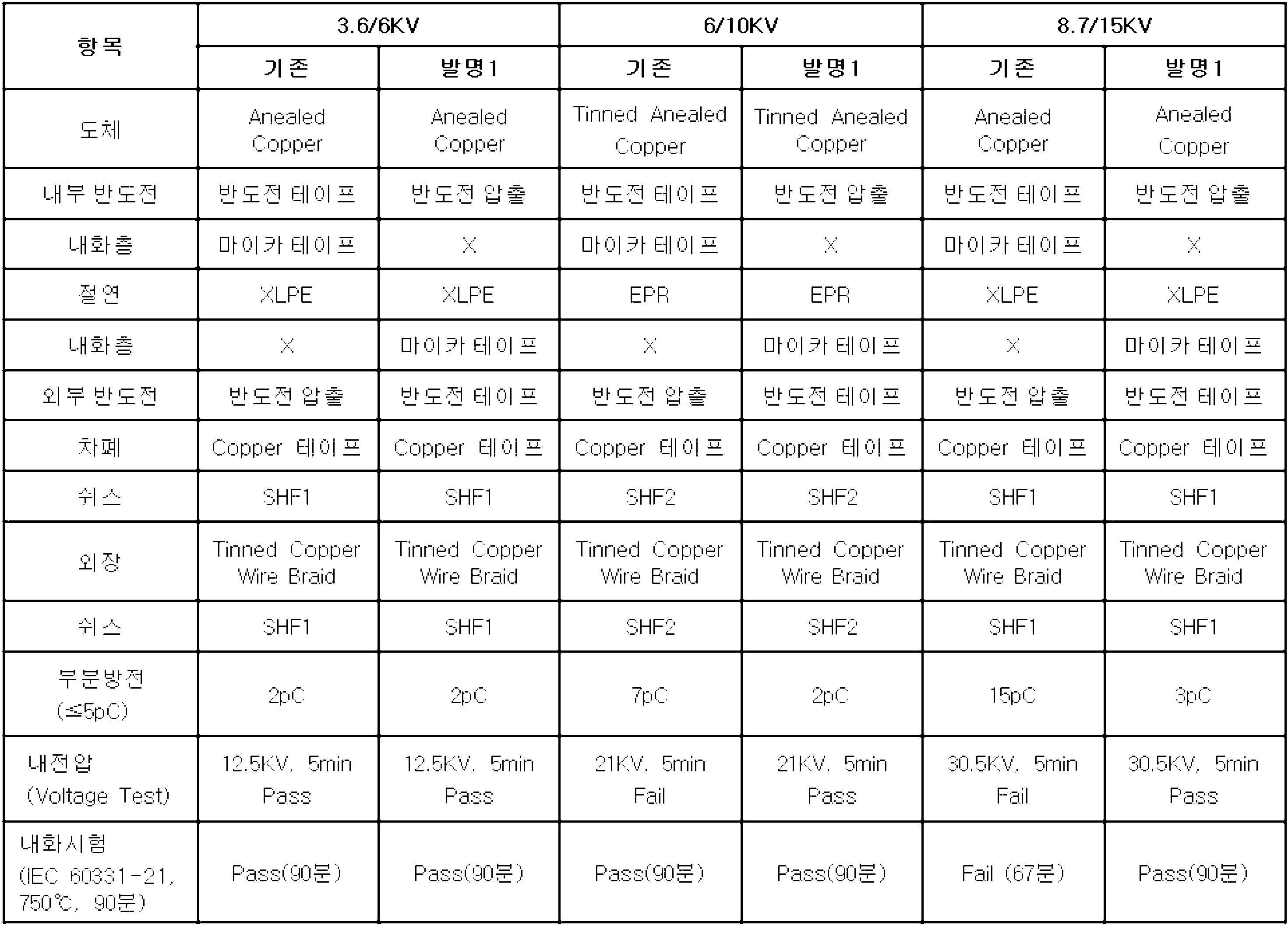
기존의 내화층(114)이 제1 반도전층(112) 즉, 내부 반도전 외측에 인접하여 형성되는 경우의 구성을 내화층(114)이 절연층(113)과 제2 반도전층(115) 사이에 형성되는 본 발명과 비교하여 각각의 전기적 특성 및 내화성능을 실험하였다.When the existing
공정 편의상 내화층(114) 즉, 마이카 테이프가 권선된 부분과 인접한 부분의 반도전은 반도전 압출보다 반도전 테이프를 권선하여 형성하는 것이 작업상 용이하므로, 본 발명에서 상기 제1 반도전층(112)인 내부 반도전은 압출로 형성되고, 상기 내화층(114)과 인접한 제2 반도전층(115) 즉, 외부 반도전은 반도전 테이프를 감아서 형성한다.For the convenience of the process, since the semiconducting of the
반대로 기존 구성에 있어서는 상기 내화층(114)과 인접한 제1 반도전층(112)이 반도전 테이프를 감아 형성되고, 상기 제2 반도전층(115)은 반도전 압출을 통해 형성된다.On the contrary, in the existing configuration, the first
작업의 용이성을 위해 상기와 같이 내화층(114)과 인접한 반도전층을 반도전 테이프를 감아 형성하였지만, 이에 한정되는 것은 아니며 내화층(114)과 인접한 반도전층을 압출을 통해 형성하는 것도 가능하다.As described above, the semiconductive layer adjacent to the
이와 같이 기존 구성의 케이블과 본 발명의 고압용 내화 케이블(100)의 전기적 특성과 내화 성능을 비교하면, 표 1에서 확인할 수 있는 바와 같이, 6kV 급 이하 제품에 대해서는 내화층(114)의 위치와 관계없이 전기적 특성(부분방전, 내전압) 및 내화성능을 만족한다. 그러나 10kV 급 이상으로 전압이 상승할 경우에는 기존 제품은 내화 성능은 만족하지만 부분방전, 내전압 등의 전기적인 성능 저하를 가져온다.Thus comparing the electrical characteristics and the fire resistance performance of the cable of the existing configuration and the high-pressure
그리고, 15kV 급 이상으로 전압을 상승시킬 경우에 기존 제품은 전기적 특성 뿐만 아니라 내화 특성도 만족시키지 못한다. 반면 본 발명 기술을 적용한 제품의 경우 6~15kV 모든 전압 등급에 대해서 전기 특성, 내화 특성을 만족하는 것을 확인할 수 있다.In addition, when the voltage is increased to 15kV or more, existing products do not satisfy not only electrical characteristics but also fire resistance characteristics. On the other hand, in the case of the product to which the present invention is applied, it can be confirmed that the electrical characteristics and the fire resistance characteristics are satisfied for all voltage levels of 6 to 15 kV.
도 4는 본 발명의 다른 실시 예에 따른 단상 고압용 내화 케이블의 단면도이고, 도 5는 본 발명의 다른 실시 예에 따른 3상 고압용 내화 케이블의 단면도이며, 도 6은 본 발명의 다른 실시 예에 따른 고압용 내화 케이블에서 제2 절연층을 형성하기 전과 후의 구조 차이를 도시한 구성도이다.4 is a cross-sectional view of a single-phase high-pressure fireproof cable according to another embodiment of the present invention, Figure 5 is a cross-sectional view of a three-phase high-pressure fireproof cable according to another embodiment of the present invention, Figure 6 is another embodiment of the present invention Figure 2 shows the structural difference before and after forming the second insulating layer in the high-pressure fireproof cable according to.
도 4 내지 도 6을 참조하여 본 발명의 다른 실시 예를 설명한다.Another embodiment of the present invention will be described with reference to FIGS. 4 to 6.
도 4에 도시된 바와 같이, 본 발명에 따른 고압용 내화 케이블(100)은 상기 내화층(114)과 제2 반도전층(115) 사이에 구비되는 제2 절연층(113b)을 더 포함하여 이루어질 수 있다. 편의상 이전 실시 예에서의 절연층(113)을 제1 절연층(113a)으로 표시하여 이를 제2 절연층(113b)과 구분하여 설명하도록 한다.As shown in FIG. 4, the high-pressure
이전 실시 예에 의한 고압용 내화 케이블(100)은 표 1에서 살펴본 바와 같이 전기적 특성과 내화 성능을 만족하였지만, 내화층(114)이 마이카 테이프(114a)와 같은 테이핑 형태로 형성되기 때문에 제1 절연층(113a)과 내화층(114), 내화층(114)과 제2 반도전층(115) 사이에 공극이 발생하여 에어포켓(114b, air pocket)이 형성되고 그에 따라 절연체 표면의 불균일에 의한 전계 집중으로 절연 파괴가 일어날 가능성이 있다.The high-pressure
제2 반도전층(115)과 테이핑된 내화층(114)의 불균일 접촉에 의한 전기특성 저하 문제를 보완하기 위해 본 발명에서는 내화층(114) 위에 추가로 제2 절연층(113b)을 압출 형성하여 제2 반도전층(115)과 내화층(114)이 직접 접하지 않고 표면이 매끈한 제2 절연층(113b)이 제2 반도전층(115)과 접촉하도록 구성하는 것이다.In order to compensate for the problem of deterioration of electrical characteristics due to uneven contact between the second
여기서, 상기 제2 절연층(113b)은 실리콘 코팅처리를 통해 형성될 수 있고, 기존의 테이핑된 내화층(114)에 의해 제1 절연층(113a)과의 사이 및 제2 반도전층(115)과의 사이에 형성되던 에어포켓(114b)을 줄이고, 도 5의 (b)에 도시한 바와 같이, 마치 매끈한 층과 같은 형태로 내화층(114)을 구성할 수 있는 장점이 있으며, 그에 따라 전기적 특성도 더욱 향상될 수 있다. Here, the second insulating
그리고, 더 나아가 상기 제2 절연층(113b) 외측에 별도의 내화층(114)과 절연층(113)이 추가로 형성되는 다층구조로 구성하여 내화성능을 향상시키는 구성도 적용될 수 있다.In addition, a configuration in which a fire resistant performance is improved by configuring a multilayer structure in which an additional
이와 같이 제2 절연층(113b)이 상기 내화층(114)과 제2 반도전층(115) 사이에 구비되는 고압용 내화 케이블(100)의 전기적 특성과 내화 성능을 표 2를 통해 기존 구성과 비교하여 설명하면 다음과 같다.As described above, the electrical characteristics and the fire resistance of the high-pressure
<표 2>TABLE 2
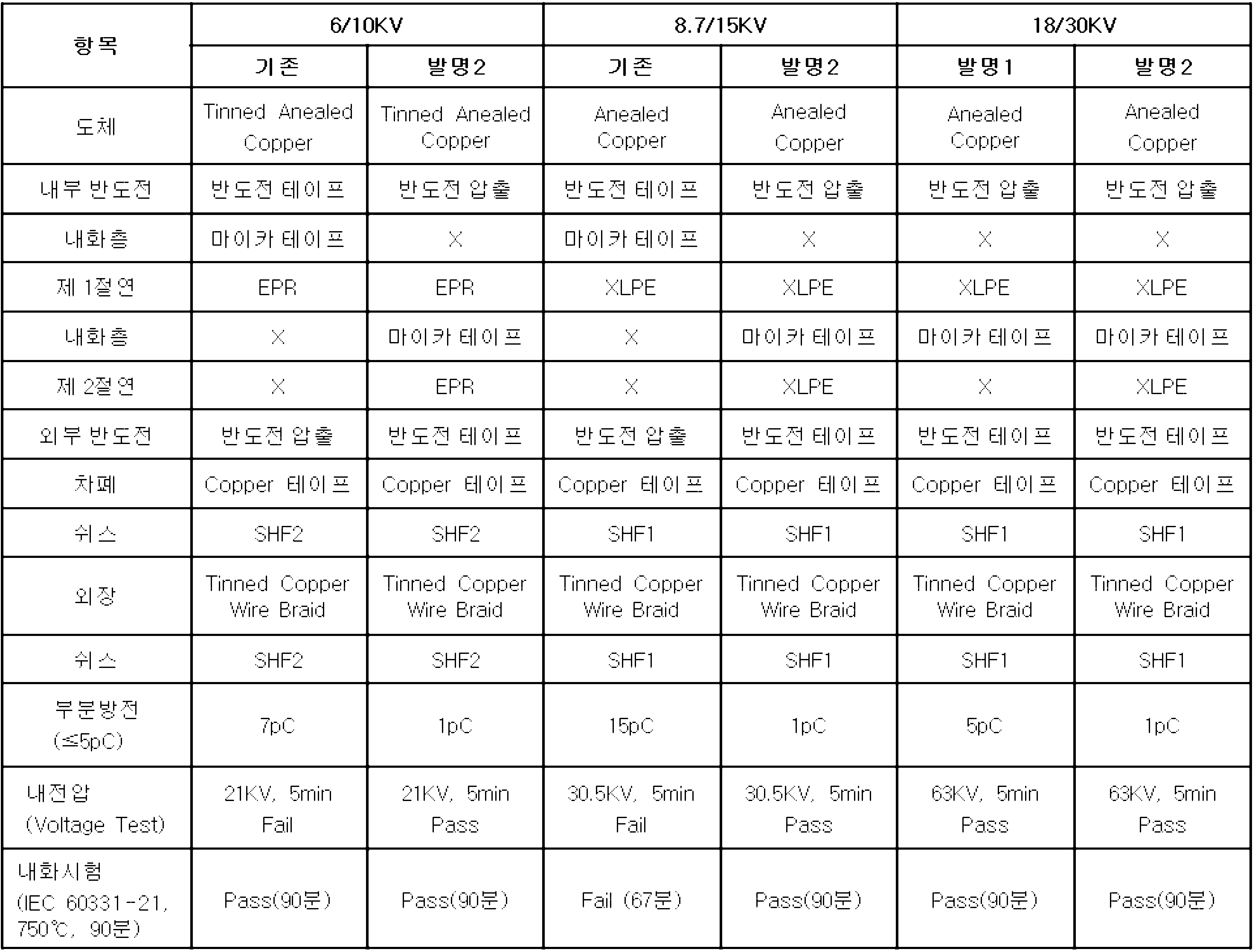
6/10kV급과 8.7/15kV급에서는 기존의 내화층(114)이 제1 반도전층(112) 즉, 내부 반도전 외측에 인접하여 형성되는 경우의 구성을 내화층(114)이 절연층(113)과 제2 반도전층(115) 사이에 형성되는 본 발명과 비교하여 각각의 전기적 특성 및 내화성능을 실험하였고, 18/30kV급에서는 제2 절연층(113b)이 없는 이전 실시 예와 제2 절연층(113b)을 형성한 경우를 비교하여 실험하였다.In the 6 / 10kV class and the 8.7 / 15kV class, the structure in which the existing
6/10kV급과 8.7/15kV급에서 비교한 바와 같이, 기존 구성은 부분방전과 내전압 등 전기적 특성과 내화성능을 모두 만족하지 못한 반면, 본 발명은 전기적 특성과 내화성능을 모두 만족하고 있다.As compared with the 6 / 10kV class and 8.7 / 15kV class, the existing configuration does not satisfy both electrical characteristics and fire resistance such as partial discharge and withstand voltage, while the present invention satisfies both electrical characteristics and fire resistance.
한편, 내화층(114)위에 제2 절연층(113b)이 없는 이전 실시 예의 경우 표 1에서 본 바와 같이, 30kV급에서는 부분방전값이 5pC수준으로 5pC 이하라는 규격을 가까스로 만족하는 수준이지만, 내화층(114) 위에 제2 절연층(113b)을 추가하는 본 발명의 경우 특히 부분방전에 대해서는 1pC 이하로 더욱 안정적인 전기적인 품질을 보여준다.On the other hand, in the case of the previous embodiment without the second insulating
따라서, 고압급의 케이블로 갈수록 전기적 특성에 대해 더욱 신경을 써야 하며, 내화층(114)과 제2 반도전층(115) 사이에 제2 절연층(113b)을 추가로 형성하는 것이 바람직함으로 확인할 수 있다.Therefore, more attention should be paid to the electrical characteristics toward the high-voltage cable, it can be confirmed that it is preferable to further form a second insulating
도 7은 도체로부터의 거리에 따른 전계강도의 변화를 나타낸 구성도이다.7 is a configuration diagram showing a change in electric field strength with distance from a conductor.
도 2 내지 7을 참조하여, 도체(111)로부터의 거리에 따른 전계 강도와 그에 따른 최적의 내화층(114) 형성 위치의 관계를 살펴보면 다음과 같다. 도 7에서 ri는 내도(내부 반도전)-절연 사이의 반지름, R은 외도(외부 반도전)-절연 사이의 반지름, t는 절연두께를 각각 나타낸다.Referring to FIGS. 2 to 7, the relationship between the electric field strength according to the distance from the
도 7에서 보는 바와 같이, 전계 강도 계산 시 도체(111) 표면에 가까운 지점일수록 전계 강도가 크다. 따라서 기존의 내화 케이블 제품과 같이 상대적으로 전계 강도가 큰 내부 반도전 위에 내화층(114) 즉, 마이카 테이프가 적용될 경우 권선된 마이카 테이프 불균일에 의한 부분방전, 절연 파괴 등의 현상이 더욱 심화되는 문제가 발생할 수 있다.As shown in FIG. 7, the closer to the surface of the
한편, 표 3은 70SQ의 10kV급과 15kV급 케이블의 시제품을 통해 내도-절연 사이의 전계 강도와 절연-외도 사이의 전계 강도를 비교한 것이다.Table 3 compares the electric field strength between the insulator-insulation and the electric field-insulation between the insulation and the insulation through prototypes of 70SQ 10kV and 15kV cables.
<표 3>TABLE 3
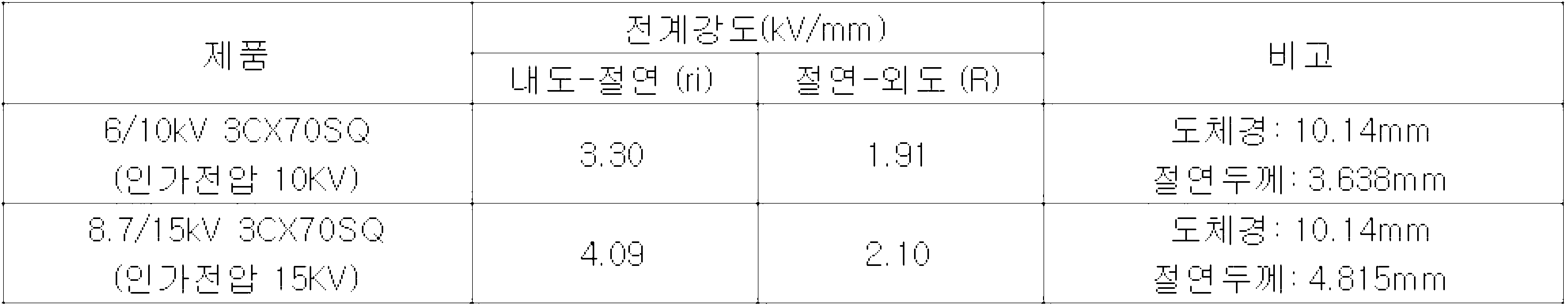
표 3에서 보는 바와 같이, 10, 15kV급 케이블에서의 전계 강도 계산시 내도-절연 사이의 전계 강도 대비 절연-외도 사이에서의 전계 강도가 약 1/2 수준으로 감소함을 알 수 있다. 즉, 절연-외도 사이에 내화층(114)을 형성하는 것이 내도-절연 사이에 내화층(114)이 위치하는 구조에 비해 전압 인가 시 전계의 영향을 1/2 수준으로 감소시키는 효과가 나타나는 것을 실제로 확인할 수 있다.As shown in Table 3, it can be seen that the electric field strength between insulation and insulation decreases to about 1/2 when the electric field strength is calculated in 10 and 15 kV class cables. That is, the formation of the
한편, 전계강도가 3kV/mm 이상인 영역에 내화층(114)이 적용될 경우 내전압, 부분방전 등의 전기 특성이 저하되는 문제가 있다. 따라서 절연층의 반경방향으로 도체에서 멀어질 수록 전계강도가 감소하며 적어도 3kV/mm 이하로 낮아지는 거리 이상에 내화층(114)이 적용되어야 한다.On the other hand, when the
반면에, 내화층(114)의 위치가 도체에서 거리가 멀어질수록 전기적 품질은 향상이 되나 절연두께가 두꺼워지므로 케이블 외경이 증가하고 중량이 증가하여 케이블 포설시 작업 편의성이 떨어지는 문제가 있다. On the other hand, as the location of the
따라서, 전기적인 품질 및 외경 최적화 수준에서 전계강도가 최소 1kV/mm 이상인 영역에 내화층(114)을 형성하는 것이 바람직하며, 결론적으로 상기 내화층(114)은 전계강도가 1kV/mm 내지 3kV/mm인 영역에 위치하는 것이 최적의 조건에 해당한다.Therefore, it is desirable to form the
지금까지 설명한 바와 같이, 본 발명은 도체(111)를 보호하면서도 상대적으로 전계 강도가 낮게 형성되는 절연층(113)과 외부 반도전인 제2 반도전층(115) 사이에 내화층(114)을 형성함으로써 내화 성능은 유지하면서 부분방전, 절연 파괴 등의 전기적은 성능을 향상시킬 수 있는 장점을 가진다.As described so far, the present invention forms a
또한, 내부 반도전인 제1 반도전층(112)과 절연층(113) 사이에 비해 곡률 반경이 큰 절연층(113)과 제2 반도전층(115) 사이에 내화층(114)을 적용함으로써 부스러지기 쉬운 마이카 테이프와 같은 재료를 적용할 경우에 보다 안정적인 제조가 가능하며, 결과적으로 내화 성능도 기존 제품보다 향상되었음을 확인할 수 있다.In addition, when the fire
상기에서는 본 발명의 바람직한 실시 예를 참조하여 설명하였지만, 해당 기술분야의 당업자는 이하에서 서술하는 특허청구범위에 기재된 본 발명의 사상 및 영역으로부터 벗어나지 않는 범위 내에서 본 발명을 다양하게 수정 및 변경 실시할 수 있을 것이다. 그러므로 변형된 실시가 기본적으로 본 발명의 특허청구범위의 구성요소를 포함한다면 모두 본 발명의 기술적 범주에 포함된다고 보아야 한다.Although the above has been described with reference to a preferred embodiment of the present invention, those skilled in the art to various modifications and changes to the present invention without departing from the spirit and scope of the invention described in the claims described below You can do it. Therefore, it should be seen that all modifications included in the technical scope of the present invention are basically included in the scope of the claims of the present invention.
100: 고압용 내화 케이블 111: 도체
112: 제1 반도전층 113, 113a: 제1 절연층
113b: 제2 절연층 114: 내화층
115: 제2 반도전층 116: 차폐층
120: 내부 쉬스층 130: 외장
140: 외부 쉬스층100: high-pressure fireproof cable 111: conductor
112: first
113b: second insulating layer 114: fireproof layer
115: second semiconducting layer 116: shielding layer
120: inner sheath layer 130: exterior
140: outer sheath layer
Claims (11)
상기 도체의 외측에 형성되는 제1 반도전층;
상기 제1 반도전층 외측에 형성되는 제1 절연층;
상기 제1 절연층 외측에 형성되는 제2 반도전층;
상기 제2 반도전층 외측에 형성되는 차폐층; 및,
상기 제1 절연층과 상기 제2 반도전층 사이에 구비되는 내화층;을 포함하고,
상기 내화층과 제2 반도전층 사이에 구비되는 제2 절연층을 더 포함하고,
상기 도체와 상기 제1 반도전층은 서로 접하며,
상기 내화층은 전계강도가 1kV/mm 내지 3kV/mm인 영역에 위치하는 것을 특징으로 하는 고압용 내화 케이블.Conductor;
A first semiconducting layer formed on the outside of the conductor;
A first insulating layer formed outside the first semiconducting layer;
A second semiconducting layer formed outside the first insulating layer;
A shielding layer formed outside the second semiconducting layer; And,
And a fireproof layer provided between the first insulating layer and the second semiconducting layer.
Further comprising a second insulating layer provided between the fireproof layer and the second semiconducting layer,
The conductor and the first semiconducting layer are in contact with each other,
The fireproof layer is a high-pressure fireproof cable, characterized in that the electric field strength is located in the region of 1kV / mm to 3kV / mm.
상기 제1 반도전층과 제1 절연층은 서로 접하는 것을 특징으로 하는 고압용 내화 케이블.The method of claim 1,
The first semiconducting layer and the first insulating layer are in contact with each other high pressure fireproof cable.
상기 차폐층 외측에 형성되는 쉬스층을 더 포함하는 고압용 내화 케이블.The method of claim 1,
Fire-resistant cable for a high pressure further comprises a sheath layer formed outside the shielding layer.
상기 제2 절연층은 실리콘 코팅처리를 통해 형성되는 것을 특징으로 하는 고압용 내화 케이블.The method of claim 1,
The second insulating layer is a high-pressure fireproof cable, characterized in that formed through the silicon coating treatment.
상기 제2 절연층 외측에 별도의 내화층과 절연층이 추가로 형성되는 다층구조로 이루어지는 것을 특징으로 하는 고압용 내화 케이블.The method of claim 1,
Fire-resistant cable for high pressure, characterized in that the multi-layer structure in which a separate fireproof layer and the insulating layer is further formed outside the second insulating layer.
상기 제1 반도전층은 압출로 형성되고, 상기 제2 반도전층은 반도전 테이프를 감아서 형성되는 것을 특징으로 하는 고압용 내화 케이블.The method of claim 1,
The first semiconducting layer is formed by extrusion, and the second semiconducting layer is formed by winding a semiconducting tape.
상기 내화층은 마이카 테이프로 이루어지며, 2회 이상 권선되는 것을 특징으로 하는 고압용 내화 케이블.The method of claim 1,
The fire-resistant layer is made of mica tape, high-pressure fireproof cable, characterized in that wound two or more times.
Priority Applications (2)
| Application Number | Priority Date | Filing Date | Title |
|---|---|---|---|
| KR1020120132527A KR102038707B1 (en) | 2012-11-21 | 2012-11-21 | fire resistant cable for medium or high voltage and manufacturing method of the same |
| PCT/KR2013/004770 WO2014081096A1 (en) | 2012-11-21 | 2013-05-30 | Fire resistant cable for medium or high voltage |
Applications Claiming Priority (1)
| Application Number | Priority Date | Filing Date | Title |
|---|---|---|---|
| KR1020120132527A KR102038707B1 (en) | 2012-11-21 | 2012-11-21 | fire resistant cable for medium or high voltage and manufacturing method of the same |
Publications (2)
| Publication Number | Publication Date |
|---|---|
| KR20140065241A KR20140065241A (en) | 2014-05-29 |
| KR102038707B1 true KR102038707B1 (en) | 2019-10-30 |
Family
ID=50776245
Family Applications (1)
| Application Number | Title | Priority Date | Filing Date |
|---|---|---|---|
| KR1020120132527A Active KR102038707B1 (en) | 2012-11-21 | 2012-11-21 | fire resistant cable for medium or high voltage and manufacturing method of the same |
Country Status (2)
| Country | Link |
|---|---|
| KR (1) | KR102038707B1 (en) |
| WO (1) | WO2014081096A1 (en) |
Families Citing this family (22)
| Publication number | Priority date | Publication date | Assignee | Title |
|---|---|---|---|---|
| CN105895238A (en) * | 2014-10-16 | 2016-08-24 | 广东南缆电缆有限公司 | Flexible composite mineral high-insulation fireproof cable |
| CN105895240A (en) * | 2014-12-25 | 2016-08-24 | 广东南缆电缆有限公司 | High-temperature-resistant flexible mineral-insulated fireproof cable |
| US20160189829A1 (en) * | 2014-12-30 | 2016-06-30 | General Cable Technologies Corporation | Multi-layer cables |
| US10515741B2 (en) | 2015-12-09 | 2019-12-24 | Prysmian S.P.A. | Fire resistant electric cable |
| CN105702329A (en) * | 2016-01-29 | 2016-06-22 | 四川明星电缆股份有限公司 | K3 fire-resisting cable and preparation technology thereof |
| CN106057344A (en) * | 2016-07-28 | 2016-10-26 | 江苏长峰电缆有限公司 | Impact-resistant spray-resistant, halogen-free, low-smoke flame-retardant medium voltage fire-resistant cable |
| KR101818880B1 (en) | 2017-03-30 | 2018-01-15 | 엘에스전선 주식회사 | Power cable |
| KR102436277B1 (en) * | 2017-05-10 | 2022-08-24 | 엘에스전선 주식회사 | Power cable |
| EP3692405B1 (en) | 2017-10-06 | 2022-07-20 | Prysmian S.p.A. | Fire resistant fibre optic cable with high fibre count |
| RU180838U1 (en) * | 2017-12-22 | 2018-06-28 | Общество с ограниченной ответственностью "ТАТКАБЕЛЬ" | FIRE RESISTANT CABLE |
| RU188841U1 (en) * | 2018-11-13 | 2019-04-25 | Общество с ограниченной ответственностью "ТАТКАБЕЛЬ" | CABLE POWER HIGH-VOLTAGE FIRE RESISTANT |
| CN109390088A (en) * | 2018-12-12 | 2019-02-26 | 安徽蒙特尔电缆集团有限公司 | A kind of insulated fireproof power cable |
| RU188805U1 (en) * | 2018-12-25 | 2019-04-24 | Общество с ограниченной ответственностью "ТАТКАБЕЛЬ" | GROUNDING WIRE, NOT DISTRIBUTING BURNING |
| RU193823U1 (en) * | 2019-08-01 | 2019-11-18 | Открытое акционерное общество Всероссийский научно-исследовательский, проектно-конструкторский и технологический институт кабельной промышленности | Power cable |
| RU193725U1 (en) * | 2019-08-05 | 2019-11-12 | Открытое акционерное общество Всероссийский научно-исследовательский, проектно-конструкторский и технологический институт кабельной промышленности | Power cable |
| RU199754U1 (en) * | 2020-04-27 | 2020-09-18 | Открытое акционерное общество Всероссийский научно-исследовательский, проектно-конструкторский и технологический институт кабельной промышленности (ВНИИ КП) | Power cable |
| RU200095U1 (en) * | 2020-04-27 | 2020-10-06 | Открытое акционерное общество Всероссийский научно-исследовательский, проектно-конструкторский и технологический институт кабельной промышленности (ВНИИКП) | Power cable |
| CN111613373A (en) * | 2020-06-04 | 2020-09-01 | 深圳金信诺高新技术股份有限公司 | A kind of high fire resistance, high strength rail transit locomotive cable |
| RU201421U1 (en) * | 2020-06-30 | 2020-12-15 | Открытое акционерное общество Всероссийский научно-исследовательский, проектно-конструкторский и технологический институт кабельной промышленности | Power cable |
| RU201420U1 (en) * | 2020-07-02 | 2020-12-15 | Открытое акционерное общество Всероссийский научно-исследовательский, проектно-конструкторский и технологический институт кабельной промышленности | Power cable |
| RU204340U1 (en) * | 2020-11-05 | 2021-05-21 | Открытое акционерное общество Всероссийский научно-исследовательский, проектно-конструкторский и технологический институт кабельной промышленности (ВНИИ КП) | Power cable |
| KR102830002B1 (en) * | 2023-08-28 | 2025-07-04 | 극동전선판매주식회사 | Coaxial power cable |
Citations (2)
| Publication number | Priority date | Publication date | Assignee | Title |
|---|---|---|---|---|
| JP2004134267A (en) * | 2002-10-11 | 2004-04-30 | Yazaki Corp | Fire resistant wire |
| JP2010182532A (en) * | 2009-02-05 | 2010-08-19 | Swcc Showa Cable Systems Co Ltd | Cable for high-voltage electronic device |
Family Cites Families (8)
| Publication number | Priority date | Publication date | Assignee | Title |
|---|---|---|---|---|
| US4476155A (en) * | 1983-04-18 | 1984-10-09 | Dow Corning Corporation | High voltage insulators |
| JPS6070604A (en) * | 1983-09-27 | 1985-04-22 | 矢崎総業株式会社 | High voltage flame resistant cable |
| JPH11345524A (en) * | 1998-06-02 | 1999-12-14 | Furukawa Electric Co Ltd:The | Fire resistant wire |
| CA2482830C (en) * | 2002-04-29 | 2012-12-18 | Pirelli & C. S.P.A. | Fire resistant cable |
| US20050045368A1 (en) * | 2003-09-02 | 2005-03-03 | Keogh Michael John | Dual layer wire and cable |
| FR2870543B1 (en) * | 2004-05-21 | 2006-07-21 | Nexans Sa | FIRE RESISTANT CABLE |
| KR101735695B1 (en) * | 2010-07-08 | 2017-05-16 | 엘에스전선 주식회사 | Highly Fire Resistant Cable |
| KR20120009146A (en) * | 2010-07-22 | 2012-02-01 | 엘에스전선 주식회사 | Wire with high fire resistance |
-
2012
- 2012-11-21 KR KR1020120132527A patent/KR102038707B1/en active Active
-
2013
- 2013-05-30 WO PCT/KR2013/004770 patent/WO2014081096A1/en not_active Ceased
Patent Citations (2)
| Publication number | Priority date | Publication date | Assignee | Title |
|---|---|---|---|---|
| JP2004134267A (en) * | 2002-10-11 | 2004-04-30 | Yazaki Corp | Fire resistant wire |
| JP2010182532A (en) * | 2009-02-05 | 2010-08-19 | Swcc Showa Cable Systems Co Ltd | Cable for high-voltage electronic device |
Also Published As
| Publication number | Publication date |
|---|---|
| WO2014081096A1 (en) | 2014-05-30 |
| KR20140065241A (en) | 2014-05-29 |
Similar Documents
| Publication | Publication Date | Title |
|---|---|---|
| KR102038707B1 (en) | fire resistant cable for medium or high voltage and manufacturing method of the same | |
| KR102533831B1 (en) | hydrocarbon fire protection cable | |
| CN108369841B (en) | Fire-resistant cable | |
| KR101706744B1 (en) | High fire resistance cable and manufacturing method thereof | |
| KR20140095155A (en) | fire resistant cable | |
| CN209912603U (en) | Environment-friendly flame-retardant fire-resistant medium-voltage power cable | |
| RU180985U1 (en) | Shielded power cable | |
| KR102710135B1 (en) | hydrocarbon fire protection cable | |
| KR102190470B1 (en) | Mica tape and fire resistant cable including the same | |
| CN202258525U (en) | Fireproof and waterproof flexible direct current transmission cable | |
| CN203706730U (en) | High-flame-retardant low smoke halogen-free medium-voltage fire resisting cable | |
| CN105976913A (en) | Improved-type medium-voltage fireproof power cable | |
| CN115171968A (en) | High-efficiency energy-saving medium-voltage fireproof cable | |
| CN211578436U (en) | Low-voltage flexible mineral insulated fireproof cable | |
| CN204102616U (en) | A kind of novel flame-retardant fireproof cable | |
| KR20170111049A (en) | Fire resistant cable | |
| CN213781625U (en) | Compound insulating flexible fireproof cable | |
| CN103854782A (en) | Environment-friendly medium-voltage fire-resistant power cable | |
| CN102117676A (en) | Fully-closed high-voltage soft bus | |
| CN106024169B (en) | A kind of high fire-retardance high life high capacity low-smoke non-halogen building cloth wire and preparation technology | |
| CN203826090U (en) | Environmental-friendly medium-voltage fire-resistant power cable | |
| KR20140094096A (en) | mica tape and fire resistant cable including the same | |
| CN202332397U (en) | Marine medium-voltage fire-proof power cable | |
| CN201893161U (en) | Soft type low smoke zero halogen cable for ship | |
| RU161088U1 (en) | POWER CABLE FOR VOLTAGE 45-330 kV |
Legal Events
| Date | Code | Title | Description |
|---|---|---|---|
| PA0109 | Patent application |
St.27 status event code: A-0-1-A10-A12-nap-PA0109 |
|
| PN2301 | Change of applicant |
St.27 status event code: A-3-3-R10-R13-asn-PN2301 St.27 status event code: A-3-3-R10-R11-asn-PN2301 |
|
| PG1501 | Laying open of application |
St.27 status event code: A-1-1-Q10-Q12-nap-PG1501 |
|
| R17-X000 | Change to representative recorded |
St.27 status event code: A-3-3-R10-R17-oth-X000 |
|
| A201 | Request for examination | ||
| PA0201 | Request for examination |
St.27 status event code: A-1-2-D10-D11-exm-PA0201 |
|
| E902 | Notification of reason for refusal | ||
| PE0902 | Notice of grounds for rejection |
St.27 status event code: A-1-2-D10-D21-exm-PE0902 |
|
| AMND | Amendment | ||
| E13-X000 | Pre-grant limitation requested |
St.27 status event code: A-2-3-E10-E13-lim-X000 |
|
| P11-X000 | Amendment of application requested |
St.27 status event code: A-2-2-P10-P11-nap-X000 |
|
| P13-X000 | Application amended |
St.27 status event code: A-2-2-P10-P13-nap-X000 |
|
| E902 | Notification of reason for refusal | ||
| PE0902 | Notice of grounds for rejection |
St.27 status event code: A-1-2-D10-D21-exm-PE0902 |
|
| AMND | Amendment | ||
| P11-X000 | Amendment of application requested |
St.27 status event code: A-2-2-P10-P11-nap-X000 |
|
| P13-X000 | Application amended |
St.27 status event code: A-2-2-P10-P13-nap-X000 |
|
| PN2301 | Change of applicant |
St.27 status event code: A-3-3-R10-R13-asn-PN2301 St.27 status event code: A-3-3-R10-R11-asn-PN2301 |
|
| E601 | Decision to refuse application | ||
| PE0601 | Decision on rejection of patent |
St.27 status event code: N-2-6-B10-B15-exm-PE0601 |
|
| T11-X000 | Administrative time limit extension requested |
St.27 status event code: U-3-3-T10-T11-oth-X000 |
|
| T13-X000 | Administrative time limit extension granted |
St.27 status event code: U-3-3-T10-T13-oth-X000 |
|
| AMND | Amendment | ||
| P11-X000 | Amendment of application requested |
St.27 status event code: A-2-2-P10-P11-nap-X000 |
|
| P13-X000 | Application amended |
St.27 status event code: A-2-2-P10-P13-nap-X000 |
|
| PX0901 | Re-examination |
St.27 status event code: A-2-3-E10-E12-rex-PX0901 |
|
| PX0701 | Decision of registration after re-examination |
St.27 status event code: A-3-4-F10-F13-rex-PX0701 |
|
| X701 | Decision to grant (after re-examination) | ||
| GRNT | Written decision to grant | ||
| PR0701 | Registration of establishment |
St.27 status event code: A-2-4-F10-F11-exm-PR0701 |
|
| PR1002 | Payment of registration fee |
St.27 status event code: A-2-2-U10-U11-oth-PR1002 Fee payment year number: 1 |
|
| PG1601 | Publication of registration |
St.27 status event code: A-4-4-Q10-Q13-nap-PG1601 |
|
| PR1001 | Payment of annual fee |
St.27 status event code: A-4-4-U10-U11-oth-PR1001 Fee payment year number: 4 |
|
| PR1001 | Payment of annual fee |
St.27 status event code: A-4-4-U10-U11-oth-PR1001 Fee payment year number: 5 |
|
| PR1001 | Payment of annual fee |
St.27 status event code: A-4-4-U10-U11-oth-PR1001 Fee payment year number: 6 |
|
| PR1001 | Payment of annual fee |
St.27 status event code: A-4-4-U10-U11-oth-PR1001 Fee payment year number: 7 |
|
| U11 | Full renewal or maintenance fee paid |
Free format text: ST27 STATUS EVENT CODE: A-4-4-U10-U11-OTH-PR1001 (AS PROVIDED BY THE NATIONAL OFFICE) Year of fee payment: 7 |