KR102032938B1 - System for preventing fall based on internet of things - Google Patents
System for preventing fall based on internet of things Download PDFInfo
- Publication number
- KR102032938B1 KR102032938B1 KR1020190051955A KR20190051955A KR102032938B1 KR 102032938 B1 KR102032938 B1 KR 102032938B1 KR 1020190051955 A KR1020190051955 A KR 1020190051955A KR 20190051955 A KR20190051955 A KR 20190051955A KR 102032938 B1 KR102032938 B1 KR 102032938B1
- Authority
- KR
- South Korea
- Prior art keywords
- guard
- control device
- window frame
- side chassis
- chassis
- Prior art date
- Legal status (The legal status is an assumption and is not a legal conclusion. Google has not performed a legal analysis and makes no representation as to the accuracy of the status listed.)
- Expired - Fee Related
Links
Images


Classifications
-
- E—FIXED CONSTRUCTIONS
- E06—DOORS, WINDOWS, SHUTTERS, OR ROLLER BLINDS IN GENERAL; LADDERS
- E06B—FIXED OR MOVABLE CLOSURES FOR OPENINGS IN BUILDINGS, VEHICLES, FENCES OR LIKE ENCLOSURES IN GENERAL, e.g. DOORS, WINDOWS, BLINDS, GATES
- E06B9/00—Screening or protective devices for wall or similar openings, with or without operating or securing mechanisms; Closures of similar construction
-
- E—FIXED CONSTRUCTIONS
- E06—DOORS, WINDOWS, SHUTTERS, OR ROLLER BLINDS IN GENERAL; LADDERS
- E06B—FIXED OR MOVABLE CLOSURES FOR OPENINGS IN BUILDINGS, VEHICLES, FENCES OR LIKE ENCLOSURES IN GENERAL, e.g. DOORS, WINDOWS, BLINDS, GATES
- E06B7/00—Special arrangements or measures in connection with doors or windows
- E06B7/28—Other arrangements on doors or windows, e.g. door-plates, windows adapted to carry plants, hooks for window cleaners
-
- G—PHYSICS
- G06—COMPUTING OR CALCULATING; COUNTING
- G06K—GRAPHICAL DATA READING; PRESENTATION OF DATA; RECORD CARRIERS; HANDLING RECORD CARRIERS
- G06K7/00—Methods or arrangements for sensing record carriers, e.g. for reading patterns
- G06K7/10—Methods or arrangements for sensing record carriers, e.g. for reading patterns by electromagnetic radiation, e.g. optical sensing; by corpuscular radiation
- G06K7/10009—Methods or arrangements for sensing record carriers, e.g. for reading patterns by electromagnetic radiation, e.g. optical sensing; by corpuscular radiation sensing by radiation using wavelengths larger than 0.1 mm, e.g. radio-waves or microwaves
-
- G—PHYSICS
- G08—SIGNALLING
- G08B—SIGNALLING OR CALLING SYSTEMS; ORDER TELEGRAPHS; ALARM SYSTEMS
- G08B3/00—Audible signalling systems; Audible personal calling systems
- G08B3/10—Audible signalling systems; Audible personal calling systems using electric transmission; using electromagnetic transmission
-
- E—FIXED CONSTRUCTIONS
- E06—DOORS, WINDOWS, SHUTTERS, OR ROLLER BLINDS IN GENERAL; LADDERS
- E06B—FIXED OR MOVABLE CLOSURES FOR OPENINGS IN BUILDINGS, VEHICLES, FENCES OR LIKE ENCLOSURES IN GENERAL, e.g. DOORS, WINDOWS, BLINDS, GATES
- E06B9/00—Screening or protective devices for wall or similar openings, with or without operating or securing mechanisms; Closures of similar construction
- E06B2009/002—Safety guards or gates
Landscapes
- Engineering & Computer Science (AREA)
- Physics & Mathematics (AREA)
- Structural Engineering (AREA)
- Electromagnetism (AREA)
- Toxicology (AREA)
- Health & Medical Sciences (AREA)
- Civil Engineering (AREA)
- General Physics & Mathematics (AREA)
- General Health & Medical Sciences (AREA)
- Artificial Intelligence (AREA)
- Computer Vision & Pattern Recognition (AREA)
- Theoretical Computer Science (AREA)
- Architecture (AREA)
- Alarm Systems (AREA)
Abstract
본 발명은 사물인터넷 기반 추락방지시스템에 관한 것으로, 적어도 하나의 가드; 고정측 샤시의 창틀에 부착되어, 가드가 하강할 때 가드를 받치는 적어도 하나의 가드 받침부; 및 가동측 샤시의 창틀에 부착되고, 가드 홀이 형성되어 가드를 가드 홀을 통해 결합하여 록킹(locking)되도록 하는 적어도 하나의 제어장치를 포함하고, 적어도 하나의 가드, 적어도 하나의 가드 받침대 및 적어도 하나의 제어장치의 개수는 동일하고, 적어도 하나의 제어장치 중의 하나의 제어장치는, RFID 리더기가 구비되어 가동측 샤시와 고정측 샤시의 사이에 문이 열려있는 상태에서 RFID 태그를 착용한 보호 대상자가 가동측 샤시에 접근할 때 RFID 태그로부터 RFID 통신을 통해 RFID 식별정보를 수신하고, 보호 대상자가 접근하였다는 것을 인식하였을 때 가드를 회전시켜 가동측 샤시의 창틀과 고정측 샤시의 창틀 사이에 가드가 걸리도록 한다.The present invention relates to an IoT based fall prevention system, comprising: at least one guard; At least one guard support portion attached to the window frame of the fixed side chassis to support the guard when the guard is lowered; And at least one control device attached to the window frame of the movable side chassis, the guard hole being formed to engage and lock the guard through the guard hole, wherein the at least one guard, at least one guard pedestal and at least The number of one control device is the same, and one of the at least one control device includes an RFID reader and a person to be protected by wearing an RFID tag with a door opened between the movable chassis and the fixed chassis. Receives RFID identification information from the RFID tag via RFID communication when approaching the movable chassis, and when the guardian recognizes that the guardian has approached, rotates the guard to guard between the window frame of the movable chassis and the fixed chassis chassis. To take.
Description
본 발명은 사물인터넷 기반 추락방지시스템에 관한 것으로, 특히 보호 대상자의 추락방지를 위해 샤시의 창틀에 부착된 사물인터넷 기반 추락방지시스템에 관한 것이다.The present invention relates to an IoT-based fall prevention system, and more particularly, to an IoT-based fall prevention system attached to a window frame of a chassis to prevent a fall of a person to be protected.
이 배경기술 부분에 기재된 사항은 발명의 배경에 대한 이해를 증진시키기 위하여 작성된 것으로서, 이 기술이 속하는 분야에서 통상의 지식을 가진 자에게 이미 알려진 종래 기술이 아닌 사항을 포함할 수 있다.The matters described in this Background section are intended to enhance the understanding of the background of the invention, and may include matters not previously known to those of ordinary skill in the art.
오래 전부터 가정과 보호시설에서 영유아 및 치매노인의 추락사고는 사회적 문제로 자리 매김하고 있으며, 현재까지도 문제를 해결하기 위한 노력이 지속되고 있다.The fall of infants and the elderly with dementia in homes and shelter has long been a social problem, and efforts to solve the problem continue to this day.
추락사고는 인지능력이 부족한 영유아(영아와 유아를 함께 일컫는 말)와 치매노인들에게 발생되는 안전사고로서, 보호자가 잠시 한눈을 팔았을 경우나 자리를 이동했을 때 발생되는 안타까운 사고이기도 하다. 인지능력이 부족한 대상자가 있는 가정과 보호시설에 사고가 발생할 때부터 보호자에게 알려주고 이를 예방할 수 있는 추락방지 시스템의 도입이 시급하다고 할 수 있다.Fall accidents are safety accidents for infants and toddlers who lack cognitive abilities (a term used to refer to infants and toddlers) and elderly people with dementia. It is urgent to introduce a fall prevention system that informs the guardian and prevents it from happening in homes and shelter where there are people with cognitive deficiency.
그러나, 현재 시장에 판매되고 있는 제품들은 창문을 닫았을 때 열리지 않게 하거나 모니터링은 되지만 창문으로 진입을 막아주고 위험상황에서 다른 곳으로 시선을 유도해 주는 제품은 없다. 또한, 창문 바깥에서 외부인의 침입을 막아 주는 방범의 역할만을 할 뿐 보호 대상자에게 위험을 알려주지는 못하고 있다. 그렇다고 창문을 닫고 불편한 생활을 감수하거나 화재가 발생했을 때 피할 수 없게 창문을 막고 생활할 수도 없다.However, products currently on the market do not open or are monitored when the window is closed, but no product prevents entry into the window and draws attention away from the danger. In addition, it only serves as a crime prevention function to prevent outsiders from invading outside the window, and does not notify the person to be protected. However, you cannot close the window, take an uncomfortable life, or inevitably block the window in case of a fire.
전술한 종래기술의 문제점을 해결하기 위한 것으로, 본 발명은 인지능력이 부족한 영유아나 치매노인들을 보호하는 보호자가 잠시 한 눈을 팔았을 경우나 자리를 이동했을 때 보호자에게 알려줌으로써 인지능력이 부족한 영유아나 치매노인들의 추락사고 또는 안전사고를 예방할 수 있게 하는 사물인터넷 기반 추락방지시스템을 제공하는 것을 목적으로 한다.In order to solve the above-mentioned problems of the prior art, the present invention is to inform the caregiver when the infant or the caregiver who protects the dementia elderly people who sold the eye for a while or moved to a place when the caregiver lacks cognitive ability It aims to provide an IoT-based fall prevention system that can prevent the fall or safety accidents of the demented elderly.
또한, 본 발명은 인지능력이 부족한 영유아나 치매노인들을 보호하는 보호자가 잠시 한 눈을 팔았을 경우나 자리를 이동했을 때 인지능력이 부족한 영유아나 치매노인들에게 접근금지 안내음을 발생시켜 인지능력이 부족한 영유아나 치매노인들의 추락사고 또는 안전사고를 예방할 수 있게 하는 사물인터넷 기반 추락방지시스템을 제공하는 것을 목적으로 한다.In addition, the present invention when the guardian to protect the infants or dementia elderly people lacking cognitive ability sells for a while or move to a place when the infants or children with dementia lacking cognitive abilities to generate a warning sound banned The object of the present invention is to provide an IoT-based fall prevention system that can prevent falls or safety accidents of infants and demented elderly people who are lacking.
또한, 본 발명은 보호자가 보호자 단말기의 애플리케이션을 통해 가드의 동작속도와 보호 대상자의 감지거리를 설정할 수 있기 때문에 필요에 따라 가드의 동작과 보호자 감지방식을 달리할 수 있게 하는 사물인터넷 기반 추락방지시스템을 제공하는 것을 목적으로 한다.In addition, the present invention is the IoT based fall prevention system that allows the guardian to set the operating speed of the guard and the sensing distance of the subject to be protected through the application of the guardian terminal, so that the operation of the guard and the guardian detection method can be changed as necessary. The purpose is to provide.
또한, 본 발명은 보호자가 보호 대상자가 있을 개연성이 있는 곳의 온습도, 공기오염도, 가스누출여부, 연기발생여부 등을 보호자 단말기를 통해 모니터링을 할 수 있는 사물인터넷 기반 추락방지시스템을 제공하는 것을 목적으로 한다.In addition, an object of the present invention is to provide a IoT-based fall prevention system that allows the guardian to monitor the temperature and humidity, air pollution, gas leakage, smoke generation, etc. where there is a probability of the subject to be protected through the guardian terminal. It is done.
본 발명의 일 실시예에 따른 사물인터넷 기반 추락방지시스템은, 적어도 하나의 가드; 고정측 샤시의 창틀에 부착되어, 가드가 하강할 때 가드를 받치는 적어도 하나의 가드 받침부; 및 가동측 샤시의 창틀에 부착되고, 가드 홀이 형성되어 가드를 가드 홀을 통해 결합하여 록킹(locking)되도록 하는 적어도 하나의 제어장치를 포함하고, 적어도 하나의 가드, 적어도 하나의 가드 받침대 및 적어도 하나의 제어장치의 개수는 동일하고, 적어도 하나의 제어장치 중의 하나의 제어장치는, RFID 리더기가 구비되어 가동측 샤시와 고정측 샤시의 사이에 문이 열려있는 상태에서 RFID 태그를 착용한 보호 대상자가 가동측 샤시에 접근할 때 RFID 태그로부터 RFID 통신을 통해 RFID 식별정보를 수신하고, 보호 대상자가 접근하였다는 것을 인식하였을 때 가드를 회전시켜 가동측 샤시의 창틀과 고정측 샤시의 창틀 사이에 가드가 걸리도록 한다.IoT based fall prevention system according to an embodiment of the present invention, at least one guard; At least one guard support portion attached to the window frame of the fixed side chassis to support the guard when the guard is lowered; And at least one control device attached to the window frame of the movable side chassis, the guard hole being formed to engage and lock the guard through the guard hole, wherein the at least one guard, at least one guard pedestal and at least The number of one control device is the same, and one of the at least one control device includes an RFID reader and a person to be protected by wearing an RFID tag with a door opened between the movable chassis and the fixed chassis. Receives RFID identification information from the RFID tag via RFID communication when approaching the movable chassis, and when the guardian recognizes that the guardian has approached, rotates the guard to guard between the window frame of the movable chassis and the fixed chassis chassis. To get caught.
여기서, 적어도 하나의 가드는 그 길이가 수동으로 다단으로 조절 가능하도록 한다.Here, the at least one guard allows the length to be manually adjusted in multiple stages.
또한, 적어도 하나의 가드 받침부는, 고정측 샤시의 창틀에 부착된 가드 받침대; 및 가드 받침대에 탑재되고, 길이가 수동으로 다단으로 조절되는 고리 몸체를 포함한다.In addition, the at least one guard support portion, the guard pedestal attached to the window frame of the fixed side chassis; And a ring body mounted on the guard pedestal, the length of which is manually adjusted in multiple stages.
또한, 적어도 하나의 제어장치는 일단과 타단이 직선형의 홈이 형성된 케이스에 내장되고, 가동측 샤시의 창틀에 부착되고 일단과 타단이 절곡되어 내측으로 돌출부를 갖도록 홈이 형성되어 케이스의 일단과 타단에 형성된 직선형의 홈에 돌출부가 슬라이드 방식으로 끼워지는 베이스 찬넬을 더 포함한다.In addition, the at least one control device is embedded in a case in which one end and the other end is formed with a straight groove, is attached to the window frame of the movable side chassis, and one end and the other end are bent so that a groove is formed to have a protrusion inward, so that one end and the other end of the case are formed. The base channel further comprises a base channel in which the projection is fitted in a slide manner in the linear groove formed in the.
또한, 적어도 하나의 제어장치는 그 높이가 수동으로 조절 가능하도록 하는 높이 조절봉이 구비되고, 높이 조절봉의 높이가 조절되어 가동측 샤시의 창틀로부터의 가드의 높이가 조절된다.In addition, the at least one control device is provided with a height adjustment rod for allowing the height to be manually adjusted, the height of the height adjustment rod is adjusted to adjust the height of the guard from the window frame of the movable side chassis.
또한, 적어도 하나의 제어장치 중의 하나의 제어장치는 보호 대상자가 접근하였다는 것을 인식하였을 때 접근금지 안내음을 발생하는 안내음 발생부를 더 포함한다.In addition, one control device of the at least one control device further includes a guide sound generating unit for generating an access prohibition guide sound when it recognizes that the person to be protected has approached.
또한, 적어도 하나의 제어장치 중의 하나의 제어장치는, 보호 대상자가 접근하였다는 것을 인식하였을 때 보호자 단말기에 감지위치정보와 보호 대상자 존재 알람신호를 송신하는 알람신호 송신부를 더 포함한다.In addition, one control device of the at least one control device further includes an alarm signal transmission unit for transmitting the detected position information and the guardian presence alarm signal to the guardian terminal when it recognizes that the guardian has approached.
본 발명에 따르면, 인지능력이 부족한 영유아나 치매노인들을 보호하는 보호자가 잠시 한 눈을 팔았을 경우나 자리를 이동했을 때 보호자에게 알려줌으로써 인지능력이 부족한 영유아나 치매노인들의 추락사고 또는 안전사고를 예방할 수 있게 한다.According to the present invention, a guardian who protects infants or dementia elderly people who lack cognitive ability sells at a glance or when they move to a guardian to inform the guardian of falling infants or dementia elderly people who have insufficient cognitive ability or safety accidents. Prevent it.
또한, 본 발명에 따르면, 인지능력이 부족한 영유아나 치매노인들을 보호하는 보호자가 잠시 한 눈을 팔았을 경우나 자리를 이동했을 때 인지능력이 부족한 영유아나 치매노인들에게 접근금지 안내음을 발생시켜 인지능력이 부족한 영유아나 치매노인들의 추락사고 또는 안전사고를 예방할 수 있게 한다.In addition, according to the present invention, when a guardian who protects infants or dementia elderly people who lack cognitive ability sells eyes for a while or moves to a place, a warning sound is generated for the infants or dementia elderly people who lack cognitive ability. Prevent children from falling or safety accidents of infants and demented elderly who lack cognitive abilities.
또한, 본 발명에 따르면, 보호자는 보호자 단말기의 애플리케이션을 통해 가드의 동작속도와 보호 대상자의 감지거리를 설정할 수 있기 때문에 필요에 따라 가드의 동작과 보호자 감지방식을 달리할 수 있게 한다.In addition, according to the present invention, since the guardian can set the operating speed of the guard and the sensing distance of the subject to be protected through the application of the guardian terminal, it is possible to change the operation of the guard and the guardian detection method as necessary.
또한, 본 발명에 따르면, 보호자가 보호 대상자가 있을 개연성이 있는 곳의 온습도, 공기오염도, 가스누출여부, 연기발생여부 등을 보호자 단말기를 통해 모니터링을 할 수 있다.In addition, according to the present invention, the guardian can monitor the temperature and humidity, air pollution, gas leakage, smoke generation, etc. where there is a probability of the subject to be protected through the guardian terminal.
도 1은 본 발명의 일 실시예에 따른 사물인터넷 기반 추락방지시스템의 블록도이다.
도 2는 본 발명의 일 실시예에 따른 가드가 하강하기 전의 상태의 개략적인 사시도이다.
도 3은 본 발명의 일 실시예에 따른 가드와 제어장치가 연결된 구조의 상세 사시도이다.
도 4는 도 2의 가드가 하강한 후의 상태의 개략적인 사시도이다.
도 5는 본 발명의 일 실시예에 따른 베이스 찬넬의 개략적인 사시도이다.
도 6은 본 발명의 일 실시예에 따른 케이스의 개략적인 사시도이다.
도 7은 본 발명의 일 실시예에 따른 제어장치가 복수일 경우의 식별번호 부여방식을 나타낸 제1 개념도이다.
도 8은 본 발명의 일 실시예에 따른 제어장치가 복수일 경우의 식별번호 부여방식을 나타낸 제2 개념도이다.
도 9는 본 발명의 일 실시예에 따른 제어장치를 단독의 센서모듈로 사용할 경우의 식별번호 부여방식을 나타낸 개념도이다.1 is a block diagram of an IoT based fall prevention system according to an embodiment of the present invention.
2 is a schematic perspective view of a state before the guard descends according to an embodiment of the present invention.
3 is a detailed perspective view of a structure in which a guard and a control device are connected according to an embodiment of the present invention.
4 is a schematic perspective view of a state after the guard of FIG. 2 is lowered.
5 is a schematic perspective view of a base channel according to an embodiment of the present invention.
6 is a schematic perspective view of a case according to an embodiment of the present invention.
7 is a first conceptual diagram illustrating a method for assigning identification numbers when there are a plurality of control apparatuses according to an embodiment of the present invention.
8 is a second conceptual diagram illustrating a method for assigning identification numbers when there are a plurality of control apparatuses according to an embodiment of the present invention.
9 is a conceptual diagram illustrating an identification number assignment method when the control device according to an embodiment of the present invention is used as a single sensor module.
본 발명의 이점 및 특징, 그리고 그것들을 달성하는 방법은 첨부되는 도면과 함께 후술되어 있는 실시예들을 참조하면 명확해질 것이다. 그러나, 본 발명은 이하에서 개시되는 실시예들에 한정되는 것이 아니라 서로 다른 다양한 형태로 구현될 수 있다. 단지 실시예들은 본 발명의 개시가 완전하도록 하고, 본 발명이 속하는 기술분야에서 통상의 지식을 가진 자에게 발명의 범주를 완전하게 알려주기 위해 제공되는 것이며, 본 발명은 청구항의 범주에 의해 정의될 뿐이다.Advantages and features of the present invention, and methods of achieving them will be apparent with reference to the embodiments described below in conjunction with the accompanying drawings. However, the present invention is not limited to the embodiments disclosed below, but may be implemented in various forms. Only the embodiments are provided so that this disclosure will be thorough, and will fully convey the scope of the invention to those skilled in the art, and the invention is defined by the scope of the claims. It is only.
먼저, 본 발명의 일 실시예에서 제어장치는 메인제어장치와 서브제어장치를 모두 포함하는 것을 의미한다. 다만, 메인제어장치와 서브제어장치를 구분할 필요가 있는 경우에는 메인제어장치와 서브제어장치로 각각 기재하였다.First, in one embodiment of the present invention, the control device means that both the main control device and the sub-control device. However, when it is necessary to distinguish between the main control device and the sub control device, the main control device and the sub control device are described respectively.
또한, 메인제어장치 및 서브제어장치가 복수인 경우에는 제1, 제2와 같이 합성된 용어를 사용하기로 한다.In the case where there are a plurality of main controllers and sub-controllers, the terms synthesized as in the first and second terms will be used.
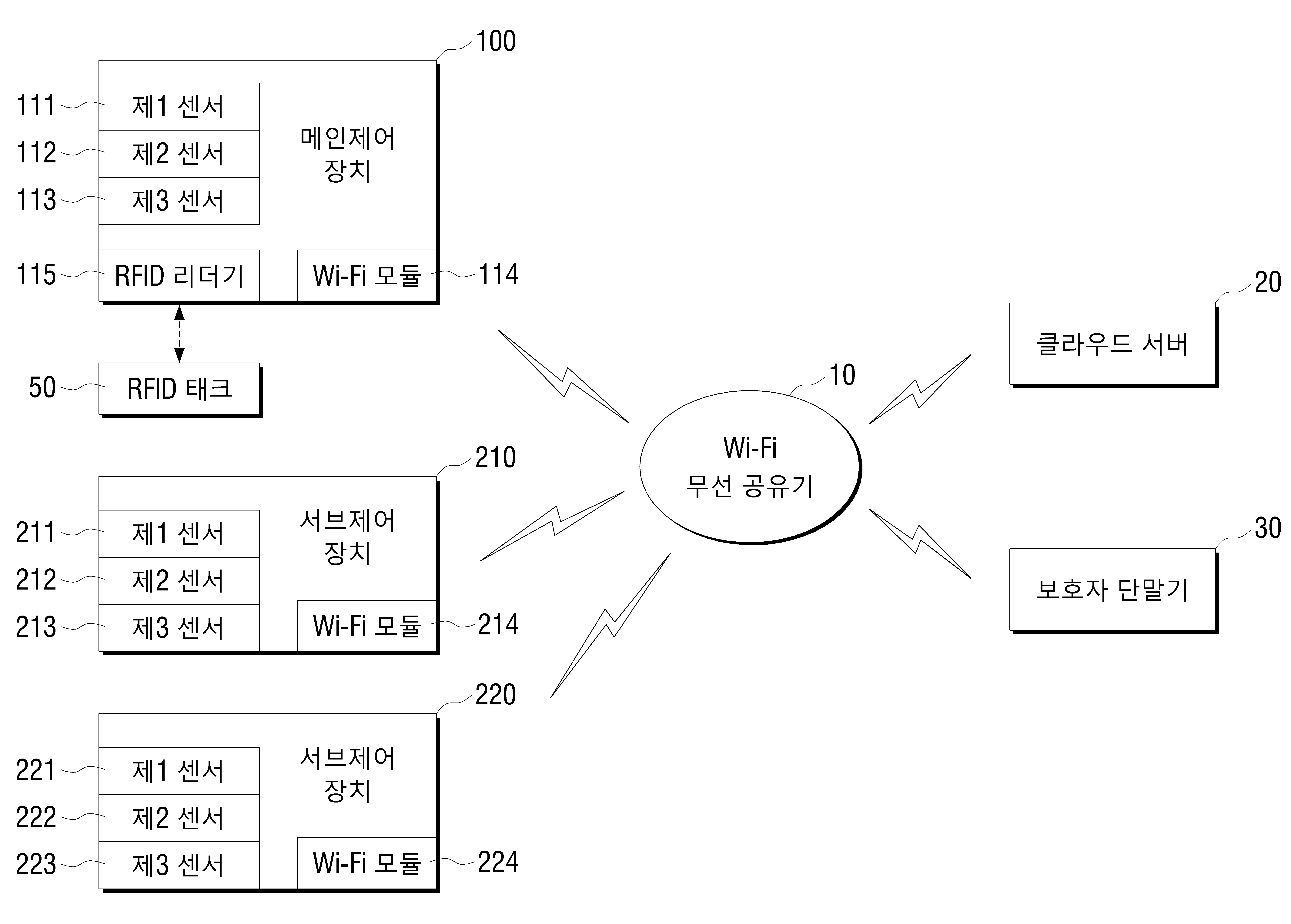
도 1은 본 발명의 일 실시예에 따른 사물인터넷 기반 추락방지시스템의 블록도이다.1 is a block diagram of an IoT based fall prevention system according to an embodiment of the present invention.
도 1을 참조하면, 1대의 메인제어장치(100)와 2대의 서브제어장치(210, 220)가 Wi-Fi 무선공유기(10)를 통해 클라우드 서버(cloud server, 20)와 보호자 단말기(30)에 무선으로 연결된 것을 나타낸다. 메인제어장치(100)와 제1 및 제2 서브제어장치(210, 220)는 제1 센서(111, 211, 221), 제2 센서(112, 212, 222), 제3 센서 (113, 213, 223) 및 Wi-Fi 모듈(114, 214, 224)이 공통적으로 구비되어 있고, 메인제어장치(100)는 RFID 리더기(Radio Frequence Identification Reader, 115)를 더 구비한다. 메인제어장치(100)와 서브제어장치(210, 220)는 각각 1대와 2대인 것으로 예를 들었다.Referring to FIG. 1, one
RFID 리더기(115)는 보호 대상자가 착용한 RFID 태그(TEG, 50)와 송수신한다. RFID 리더기(115)는 일반적으로 잘 알려져 있으므로 상세한 설명은 생략하기로 한다.The
클라우드 서버(cloud server, 20)는 메인제어장치(100)와 제1 및 제2 서브제어장치(210, 220)가 Wi-Fi 통신을 통해 송신한 모든 정보를 저장한다. The
보호자 단말기(30)는 메인제어장치(100)와 제1 및 제2 서브제어장치(210, 220)로부터 보호 대상자의 감지위치정보와 보호 대상자 존재 알람신호를 수신한다. 보호자는 보호자용 애플리케이션을 보호자 단말기(30)에 다운로드하여 설치함으로써, 보호자용 애플리케이션의 실행을 통해 사물인터넷 기반 추락방지시스템에 접속할 수 있다.The
또한, 보호자 단말기(30)는 스마트 폰(smartphone), 데스크톱 컴퓨터(desktop computer), PDA 등과 같은 모바일 통신단말일 수 있으며, 이에 한정되지는 않는다.In addition, the
도 2는 본 발명의 일 실시예에 따른 가드가 하강하기 전의 상태의 개략적인 사시도이고, 도 3은 본 발명의 일 실시예에 따른 가드와 제어장치가 연결된 구조의 상세 사시도이며, 도 4는 도 2의 가드가 하강한 후의 상태의 개략적인 사시도이다.2 is a schematic perspective view of a state before the guard descends according to an embodiment of the present invention, Figure 3 is a detailed perspective view of the structure connected to the guard and the control device according to an embodiment of the present invention, Figure 4 is a view 2 is a schematic perspective view of the state after the guard of 2 is lowered.
도 2 및 도 4를 참조하면, 사물인터넷 기반 추락방지시스템은 가드(300), 가드 받침부(400) 및 제어장치(100, 210, 220)를 포함할 수 있다. 2 and 4, the IoT-based fall prevention system may include a
가드(300)는 추락방지시스템에서 보호 대상자의 추락방지를 위해 보호 대상자가 접근하면 회전하여 가동측 샤시의 창틀(60)과 고정측 샤시의 창틀(70) 사이에 걸린다. 가드(300)는 제어장치(100, 210, 220)가 모터(도시되지 않음)를 구동시켜 회전할 수 있으며, 모터는 배터리(도시되지 않음)로부터 전원을 공급받으며, 감속기 형태의 직류 모터(direct current motor)가 사용된다.The
가드(300)의 동작과 관련하여, 가동측 샤시가 닫히면 가드(300)는 올라가 있고(회전하기 전의 상태), 가동측 샤시가 열리면 가드(300)는 내려온다. 가동측 샤시의 열림을 감지하기 위해 제어장치(100, 210, 220)의 측면에는 제어장치(100, 210, 220)와 무선으로 연결된 근접센서(도시되지 않음)가 설치될 수 있다.In connection with the operation of the
또한, 가드(300)는 적어도 하나일 수 있으며, 그 길이가 수동으로 다단으로 조절 가능하도록 한다. 본 발명의 일 실시예에서는 편의상 가드(300)가 3개인 것으로 하여 설명하였다. 도 2 및 도 4에서 가드(300)의 길이는 3단으로 조절된 것을 보이고 있는데, 창문이 열려있는 경우에 따라 가드(300)의 길이를 달리할 수 있다. 또한, 가드(300)의 개수도 다양하게 설정될 수 있다.In addition, the
가드 받침부(400)는 고정측 샤시의 창틀(70)에 부착되어, 가드(300)가 하강할 때 가드(300)를 받친다. 가드 받침부(400)는 적어도 하나일 수 있다. 가드 받침부(400)를 원형 고정판의 바닥에 부착할 때 접착력이 강한 3M 양면 테이프가 사용되어 부착된다.The
또한, 가드 받침부(400)는 고정측 샤시의 창틀(70)에 부착된 가드 받침대 (410)와, 가드 받침대(410)에 탑재되고 길이가 수동으로 다단으로 조절되는 고리 몸체(420)를 포함한다. 가드 받침대(410)의 바닥면은 원형자석이 사용되어 고정판에 부착된다. 고리 몸체(420)는 가드 받침대(410)와 볼트(bolt)로 고정되거나 일체형으로 조립된다.In addition, the
도 3을 참조하면, 제어장치는 LCD 디스플레이 장치(116), 높이 조절봉(120), 센서모듈(119), 버튼 스위치(button switch, 118), 배터리(battery, 도시되지 않음), 모터(도시되지 않음), RFID 통신모듈(또는 RFID 리더기)(115), Wi-Fi 모듈(도시되지 않음)을 포함한다. RFID 통신모듈(115)과 Wi-Fi 모듈(도시되지 않음)은 메인회로(main circuit)에 내장되어 있다.Referring to FIG. 3, the control device includes an
RFID 통신을 위한 주파수는 인식거리에 따라 13.56Mhz 또는 860~960Mhz의 범위이다. RFID 리더기(115)는 RFID 태그의 정보를 활용하기 위해 RFID 태그와 송수신한다. 도 1의 메인제어장치(100)의 설정모드에서 태그등록항목을 선택하고 태그가 인식되면 태그의 고유 데이터를 저장하여 등록할 수 있다. RFID 태그의 데이터를 삭제하려면 태그 데이터 삭제항목을 선택한다.Frequency for RFID communication is in the range of 13.56Mhz or 860 ~ 960Mhz depending on the recognition distance. The
메인제어장치(100)에는 LCD 디스플레이 장치(116)를 통해 사용자에게 설정값이나 현재 상태가 표시된다. LCD 디스플레이 장치(116) 대신에 터치 LCD, FND가 사용될 수도 있다. 도 2에서는 제어장치(100, 210, 220)가 가동측 샤시의 창틀(60)에 부착된 것을 도시하였으나, 고정측 샤시의 창틀(70)에 부착되는 것도 가능하다. 사용자는 필요에 따라 원하는 샤시의 창틀에 제어장치(100, 210, 220)를 부착시킬 수 있다.The
또한, 제어장치(100, 210, 220)는 가동측 샤시의 창틀(60)에 부착되고, 가드 홀(121)이 형성되어 가드(300)를 가드 홀(121)을 통해 결합하여 록킹(locking)되도록 한다. 제어장치(100, 210, 220)는 적어도 하나일 수 있으며, 도 1에 도시된 바와 같이 Wi-Fi 모듈(114)에서 Wi-Fi 무선 공유기(10)를 통해 클라우드 서버(cloud server, 20) 및 보호자 단말기 (30)와 Wi-Fi 통신이 가능하다.In addition, the control device (100, 210, 220) is attached to the
메인제어장치(100)는 도 1에 도시된 바와 같이 RFID 모듈(115)이 더 구비된다. 즉, 메인제어장치(100)에는 RFID 리더기(115)와 Wi-Fi 모듈(114)이 모두 구비되어 있고, 서브제어장치(210, 220)에는 Wi-Fi 모듈(214, 224)은 구비되어 있고 RFID 리더기는 구비되어 있지 않다.The
메인제어장치(100)가 2곳 이상의 장소에 설치될 경우, 버튼 스위치(118)를 3초동안 누르면 번호설정모드로 진입할 수 있다. 메인제어장치(100)의 번호설정항목에서 메인제어장치(100)의 번호를 설정할 수 있다. 버튼 스위치(118)의 누름시간은 3초에만 한정되지 않고 달리 설정될 수 있다.When the
서브제어장치(210, 220)가 2대 이상일 경우, 버튼 스위치(118)를 3초동안 누르면 번호설정모드로 진입할 수 있다. 서브제어장치(210, 220)의 번호설정항목에서 서브제어장치(210, 220)의 번호를 설정할 수 있다. 버튼 스위치(118)의 누름시간은 3초에만 한정되지 않고 달리 설정될 수 있다.When there are two or more
또한, 메인제어장치(100)는 가동측 샤시와 고정측 샤시의 사이에 문이 열려있는 상태에서 RFID 태그를 착용한 보호 대상자가 가동측 샤시에 접근할 때 RFID 태그로부터 RFID 통신을 통해 RFID 식별정보를 수신하고, 보호 대상자가 접근하였다는 것을 인식하였을 때 가드(300)를 회전시켜 가동측 샤시의 창틀(60)과 고정측 샤시의 창틀(70) 사이에 가드(300)가 걸리도록 한다.In addition, the
또한, 제어장치(100, 210, 220)는 그 높이가 수동으로 조절 가능하도록 하는 높이 조절봉(120)이 구비되고, 높이 조절봉(120)의 높이가 조절되어 가동측 샤시의 창틀(60)로부터의 가드(300)의 높이가 조절된다. 예를 들면, 높이 조절봉(120)의 높이는 도 2 및 도 4에 도시된 바와 같이 3단으로 조절될 수 있다. 각 단마다 록(lock)이 걸린다. 록의 해제를 위해서는, 록 핀(도시되지 않음)을 손으로 눌러 해제할 수 있다.In addition, the control device (100, 210, 220) is provided with a
LCD 디스플레이 장치(116)는 제어장치(100, 210, 220) 전면의 상단에 위치하며 돌출형이 아닌 매립형태를 갖는다. 즉, 제어장치(100, 210, 220)의 케이스 내측에 위치한다.The
또한, 메인제어장치(100)는 보호 대상자가 접근하였다는 것을 인식하였을 때 접근금지 안내음을 발생하는 안내음 발생부(도시되지 않음)를 더 포함할 수 있다. 이렇게 하여, 보호 대상자는 보호자가 없는 상태에서도 추락사고 또는 안전사고의 위험을 피할 수 있게 된다.In addition, the
또한, 메인제어장치(100)는 보호 대상자가 접근하였다는 것을 인식하였을 때 보호자 단말기(30)에 감지위치정보와 보호 대상자 존재 알람신호를 송신하는 알람신호 송신부(도시되지 않음)를 더 포함할 수 있다. 이렇게 하여, 보호자는 보호 대상자가 어느 곳에 있는지 신속히 알 수 있게 됨으로써 보호자를 위한 신속한 후속조치가 가능하게 된다.In addition, the
또한, 보호자는 보호자 단말기(30)의 애플리케이션을 통해 가드(300)의 동작속도와 보호 대상자의 감지거리를 설정할 수 있다. 이렇게 하여, 필요에 따라 가드 (300)의 동작과 보호자 감지방식을 달리할 수 있다.In addition, the guardian can set the operating speed of the
도 5는 본 발명의 일 실시예에 따른 베이스 찬넬의 개략적인 사시도이고, 도 6은 본 발명의 일 실시예에 따른 케이스의 개략적인 사시도이다.5 is a schematic perspective view of a base channel according to an embodiment of the present invention, Figure 6 is a schematic perspective view of a case according to an embodiment of the present invention.
도 1, 도 2, 도 4, 도 5 및 도 6을 참조하면, 제어장치(100, 210, 220)는 일단과 타단에 직선형의 홈이 형성된 케이스(case, 80)에 내장된다. 베이스 찬넬(500)은 가동측 샤시의 창틀(60)에 부착되고 일단과 타단이 절곡되어 내측으로 돌출부(510)를 갖도록 홈이 형성되어 케이스(80)의 일단과 타단에 형성된 직선형의 홈(81)에 돌출부(510)가 슬라이드 방식으로 끼워진다. 즉, 베이스 찬넬(500)은 케이스(80)의 일단으로부터 타단으로 밀착되어 록(lock)이 걸리는 구조를 갖는다.Referring to FIGS. 1, 2, 4, 5, and 6, the
이와 같은 베이스 찬넬(500)은 제어장치의 하중을 버틸 수 있도록 형성되어 있다. 베이스 찬넬(500)은 가드(300)가 하강할 때 발생하는 충격과 진동에 의한 흔들림을 최소화하기 위한 것이데, 베이스 찬넬(500)을 가동측 샤시의 창틀(60)에 부착할 때 접착력이 강한 3M 양면 테이프를 사용한다.The
베이스 찬넬(500)은 사각형의 형상을 갖고, 중앙과 4곳의 모서리에 원형자석 (520, 530)이 사용되어 제어장치와 밀착된 상태에서도 이중으로 부착되어 고정되기 때문에 제어장치(100, 210, 220)의 하중을 버틸 수 있게 된다. 중앙의 원형자석(520)은 4곳의 모서리의 원형자석(530)보다 큰데, 이러한 이유는 중앙에서 자석의 힘이 강해야 중심을 잡을 수 있기 때문이다.The
베이스 찬넬(500)의 하중이 골고루 분포되도록 하기 위해, 4곳의 모서리의 원형자석(530)은 동일한 크기로 형성되며, 베이스 찬넬(500)의 일단과 타단의 원형자석(530)은 서로 대칭되도록 형성되는 것이 바람직하다.In order to distribute the load of the
도 7은 본 발명의 일 실시예에 따른 제어장치가 복수일 경우의 식별번호 부여방식을 나타낸 제1 개념도이고, 도 8은 본 발명의 일 실시예에 따른 제어장치가 복수일 경우의 식별번호 부여방식을 나타낸 제2 개념도이다.7 is a first conceptual diagram illustrating a method for assigning identification numbers when there are a plurality of control devices according to an embodiment of the present invention, and FIG. 8 is for providing identification numbers when there are a plurality of control devices according to an embodiment of the present invention. The second conceptual diagram showing the method.
도 7 및 도 8에서는 a의 공간(방1)과 b의 공간(방2)가 있다고 하자.In FIG. 7 and FIG. 8, it is assumed that there is a space (room 1) of a and a space (room 2) of b.
도 7을 참조하면, 제어장치가 복수일 경우를 예를 들면, A의 장소(집)의 a의 공간(방1)에 제1 메인제어장치(110) "a1b0", 제1 서브제어장치(210) "a1b1", 제2 서브제어장치(220) "a1b2", 제3 서브제어장치(230) "a1b3"과 같은 식별번호가 부여된다.Referring to FIG. 7, for example, when there are a plurality of control devices, the first
도 8을 참조하면, 제어장치가 복수일 경우를 예를 들면, B의 장소(집)의 b의 공간(방2)에 제1 메인제어장치(110) "b1bo", 제1 서브제어장치(210) "b1b1", 제2 서브제어장치(220) "b1b2", 제3 서브제어장치(230) "b1b3"과 같은 식별번호가 부여된다.Referring to FIG. 8, in the case where there are a plurality of control devices, for example, the first
또한, 제어장치가 복수일 경우, A의 장소(집)의 a의 공간(방1)에 제2 메인제어장치(120) "a2b0"와 같은 식별번호가 부여되었다고 하자. 이때, a의 공간(방1)에 제4 서브제어장치(240)를 제2 메인제어장치(120)에 연결할 때 "a2b4"와 같은 식별번호가 부여된다.In the case where there are a plurality of control devices, it is assumed that an identification number such as "a2b0" of the second
제어장치를 단독의 센서모듈로 사용할 경우, A의 장소(집)의 a의 공간(방1)에서 제어장치가 추락방지기능을 제외한 센서모듈의 역할을 단독으로 사용한다고 하자. 이때, 설정항목에서 센서모듈을 단독으로 사용할 것을 선택하고 사용하고자 하는 센서모듈을 선택할 수 있다.If the control device is used as a single sensor module, it is assumed that the control device uses the role of the sensor module exclusively of the fall prevention function in the space (room 1) of a in the place (house) of A. In this case, it is possible to select to use the sensor module alone in the setting item and to select the sensor module to be used.
예를 들면, 사용자는 온습도 센서(temperature-humidity sensor), 공기오염도 측정센서, 가스센서, 연기센서 등의 센서모듈을 제어장치에 부착할 수 있다. 이렇게 하여, 보호자는 보호 대상자가 있을 가능성이 있는 곳의 온습도, 공기오염도, 가스누출여부, 연기발생여부 등을 보호자 단말기를 통해 모니터링 할 수 있다.For example, a user may attach a sensor module such as a temperature-humidity sensor, an air pollution measurement sensor, a gas sensor, a smoke sensor, and the like to the control device. In this way, the guardian can monitor the temperature and humidity, air pollution, gas leakage, smoke generation, etc. where there is a possibility of the subject of protection through the guardian terminal.
또한, 제어장치를 단독의 센서모듈로 사용할 경우 센서모듈을 3개까지 복수로 설정할 수 있으며, 선택항목은 사용자의 확인이 가능할 수 있게 체크되도록 표시한다.In addition, when the control device is used as a single sensor module, a plurality of sensor modules can be set up to three, and the selected items are marked to be checked so that the user can check them.
센서모듈은 제어장치의 하단에 커넥터(connector) 또는 단자 핀과 연결되며, 밀어서 끼우는 구조를 갖는다. 센서모듈이 커넥터 또는 단자 핀과 연결되면, LCD 디스플레이 장치에 센서모듈이 1번 위치, 2번 위치, 3번 위치에 연결되어 있다는 것이 표시된다. 센서모듈이 어떤 위치에 연결되었음에도 불구하고 인식되지 않는다면, 설정모드에서 자기진단모드로 진입하여 설정을 초기화할 수 있다.The sensor module is connected to the connector (connector) or the terminal pin at the bottom of the control device, it has a structure to push. When the sensor module is connected to the connector or terminal pin, the LCD display shows that the sensor module is connected to the 1st, 2nd and 3rd positions. If the sensor module is not recognized even though it is connected to a certain position, it can enter the self-diagnosis mode from the setting mode and initialize the setting.
센서모듈은 그 위치에 따라 센서모듈의 종류를 구분하지 않는다. 예를 들면, 1번 위치에는 공기센서모듈만 사용되지 않고 2번 위치 또는 3번 위치에서는 사용할 수 있다. 센서모듈이 모두 사용되지 않는 경우, 즉 센서모듈이 모두 커넥터 또는 단자 핀가 연결되지 않으면 자동으로 측정할 수 없다.The sensor module does not classify the type of sensor module according to its position. For example, the air sensor module is not used in position 1 but can be used in position 2 or position 3. If all sensor modules are not used, that is, if all sensor modules are not connected with connectors or terminal pins, measurement cannot be done automatically.
도 9는 본 발명의 일 실시예에 따른 제어장치를 단독의 센서모듈로 사용할 경우의 식별번호 부여방식을 나타낸 개념도이다.9 is a conceptual diagram illustrating an identification number assignment method when the control device according to an embodiment of the present invention is used as a single sensor module.
도 9를 참조하면, 제어장치를 단독의 센서모듈로 사용할 경우, A의 장소(집)의 a의 공간(방1)에 제1 메인제어장치(110) "aa0", 제2 메인제어장치(120) "ab0", 제3 메인제어장치(130) "ac0"의 순서로 식별번호가 부여된다.Referring to FIG. 9, when the control device is used as a single sensor module, the first
마찬가지로, A의 장소(집)의 b의 공간에 제1 메인제어장치(110) "ba0", 제2 메인제어장치(120) "bb0", 제3 메인제어장치(130) "bc0"의 순서로 식별번호가 부여된다.Similarly, the order of the first
전술한 본 발명의 실시예들은 이해를 돕기 위하여 도면에 도시된 실시예들을 참고로 설명되었으나, 이는 예시적인 것에 불과하며, 당해 분야에서 통상적 지식을 가진 자라면 이로부터 다양한 변형 및 균등한 타 실시예가 가능하다는 점을 이해할 것이다. 따라서, 본 발명의 진정한 기술적 보호 범위는 첨부된 청구범위에 의해 정해져야 할 것이다.Although the above-described embodiments of the present invention have been described with reference to the embodiments shown in the drawings for clarity, this is merely an example, and those skilled in the art may have various modifications and equivalent embodiments therefrom. I understand that it is possible. Therefore, the true technical protection scope of the present invention will be defined by the appended claims.
1O : Wi-Fi 무선 공유기 20 : 클라우드 서버
30 : 보호자 단말기 50 : RFID 태크
60 : 가동측 샤시의 창틀 70 : 고정측 샤시의 창틀
80 : 케이스 81 : 홈
1OO, 110, 120 : 메인제어장치 111, 211, 221 : 제1 센서
112, 212, 222 : 제2 센서 113, 213, 223 : 제3 센서
113, 214, 224 : Wi-Fi 모듈 115 : RFID 리더기
116 : LCD 디스플레이 장치 118 : 버튼 스위치
119 : 센서모듈 120 : 높이 조절봉
121 : 가드 홀 210, 220 : 서브제어장치
300 : 가드 400 : 가드 받침부 410 : 가드 받침대 420 : 고리 몸체 500 : 베이스 찬넬 510, 520, 530 : 원형자석1O: Wi-Fi Router 20: Cloud Server
30: guardian terminal 50: RFID tag
60: window frame of the movable side chassis 70: window frame of the fixed side chassis
80: case 81: groove
100, 110, 120:
112, 212, 222:
113, 214, 224 Wi-Fi Module 115: RFID Reader
116: LCD display device 118: button switch
119: sensor module 120: height adjustment rod
121:
300: guard 400: guard base 410: guard base 420: ring body 500:
Claims (7)
고정측 샤시의 창틀에 부착되어, 상기 가드가 하강할 때 상기 가드를 받치는 적어도 하나의 가드 받침부; 및
가동측 샤시의 창틀에 부착되고, 가드 홀이 형성되어 상기 가드를 상기 가드 홀을 통해 결합하여 록킹(locking)되도록 하는 적어도 하나의 제어장치
를 포함하고,
상기 적어도 하나의 가드, 상기 적어도 하나의 가드 받침대 및 상기 적어도 하나의 제어장치의 개수는 동일하고,
상기 적어도 하나의 제어장치 중의 하나의 제어장치는, RFID 리더기가 구비되어 상기 가동측 샤시와 상기 고정측 샤시의 사이에 문이 열려있는 상태에서 RFID 태그를 착용한 보호 대상자가 상기 가동측 샤시에 접근할 때 RFID 태그로부터 RFID 통신을 통해 RFID 식별정보를 수신하고, 보호 대상자가 접근하였다는 것을 인식하였을 때 상기 가드를 회전시켜 상기 가동측 샤시의 창틀과 상기 고정측 샤시의 창틀 사이에 상기 가드가 걸리도록 하는 것을 특징으로 하는 사물인터넷 기반 추락방지시스템.
At least one guard;
At least one guard supporting portion attached to the window frame of the fixed side chassis to support the guard when the guard is lowered; And
At least one control device attached to the window frame of the movable side chassis, wherein a guard hole is formed to couple and lock the guard through the guard hole
Including,
The number of the at least one guard, the at least one guard pedestal and the at least one control device is the same,
One control device of the at least one control device is provided with an RFID reader, and a person who is protected by wearing an RFID tag while the door is opened between the movable side chassis and the fixed side chassis approaches the movable side chassis. When the RFID tag receives RFID identification information from the RFID tag through RFID communication and recognizes that the person to be protected has approached, the guard is rotated so that the guard is caught between the window frame of the movable side chassis and the window frame of the fixed side chassis. IoT-based fall prevention system, characterized in that.
상기 적어도 하나의 가드는 그 길이가 수동으로 다단으로 조절 가능하도록 하는 것을 특징으로 하는 사물인터넷 기반 추락방지시스템.
The method of claim 1,
The at least one guard of the IoT-based fall prevention system, characterized in that the length can be manually adjusted in multiple stages.
상기 적어도 하나의 가드 받침부는,
상기 고정측 샤시의 창틀에 부착된 가드 받침대; 및
상기 가드 받침대에 탑재되고, 길이가 수동으로 다단으로 조절되는 고리 몸체
를 포함하는 것을 특징으로 하는 사물인터넷 기반 추락방지시스템.
The method of claim 1,
The at least one guard support portion,
A guard pedestal attached to the window frame of the fixed side chassis; And
Ring body mounted on the guard pedestal, the length is manually adjusted in multiple stages
IoT-based fall prevention system, characterized in that it comprises a.
상기 적어도 하나의 제어장치는 일단과 타단에 직선형의 홈이 형성된 케이스에 내장되고,
상기 가동측 샤시의 창틀에 부착되고 일단과 타단이 절곡되어 내측으로 돌출부를 갖도록 홈이 형성되어 상기 케이스의 일단과 타단에 형성된 직선형의 홈에 상기 돌출부가 슬라이드 방식으로 끼워지는 베이스 찬넬을 더 포함하는 것을 특징으로 하는 사물인터넷 기반 추락방지시스템.
The method of claim 1,
The at least one control device is embedded in a case in which a straight groove is formed at one end and the other end,
And a base channel attached to the window frame of the movable side chassis and having a groove formed so that one end and the other end are bent to have a protrusion inwardly, and the protrusion is slide-fitted into a linear groove formed at one end and the other end of the case. IoT-based fall prevention system, characterized in that.
상기 적어도 하나의 제어장치는 그 높이가 수동으로 조절 가능하도록 하는 높이 조절봉이 구비되고, 상기 높이 조절봉의 높이가 조절되어 상기 가동측 샤시의 창틀로부터의 상기 가드의 높이가 조절되는 것을 특징으로 하는 사물인터넷 기반 추락방지시스템.
The method of claim 1,
The at least one control device is provided with a height adjusting rod for allowing the height to be manually adjusted, the height of the height adjusting rod is adjusted so that the height of the guard from the window frame of the movable side chassis is adjusted Internet based fall prevention system.
상기 적어도 하나의 제어장치 중의 하나의 제어장치는 보호 대상자가 접근하였다는 것을 인식하였을 때 접근금지 안내음을 발생하는 안내음 발생부를 더 포함하는 것을 특징으로 하는 사물인터넷 기반 추락방지시스템.
The method of claim 1,
One control device of the at least one control device further comprises a guide sound generating unit for generating a sound guide prohibition of access when it recognizes that the person to be protected has approached.
상기 적어도 하나의 제어장치 중의 하나의 제어장치는, 보호 대상자가 접근하였다는 것을 인식하였을 때 보호자 단말기에 감지위치정보와 보호 대상자 존재 알람신호를 송신하는 알람신호 송신부를 더 포함하는 것을 특징으로 하는 사물인터넷 기반 추락방지시스템.The method of claim 1,
One control device of the at least one control device further comprises an alarm signal transmission unit for transmitting the detected position information and the guardian presence alarm signal to the guardian terminal when it recognizes that the guardian is approaching. Internet based fall prevention system.
Priority Applications (1)
| Application Number | Priority Date | Filing Date | Title |
|---|---|---|---|
| KR1020190051955A KR102032938B1 (en) | 2019-05-03 | 2019-05-03 | System for preventing fall based on internet of things |
Applications Claiming Priority (1)
| Application Number | Priority Date | Filing Date | Title |
|---|---|---|---|
| KR1020190051955A KR102032938B1 (en) | 2019-05-03 | 2019-05-03 | System for preventing fall based on internet of things |
Publications (1)
| Publication Number | Publication Date |
|---|---|
| KR102032938B1 true KR102032938B1 (en) | 2019-10-16 |
Family
ID=68421518
Family Applications (1)
| Application Number | Title | Priority Date | Filing Date |
|---|---|---|---|
| KR1020190051955A Expired - Fee Related KR102032938B1 (en) | 2019-05-03 | 2019-05-03 | System for preventing fall based on internet of things |
Country Status (1)
| Country | Link |
|---|---|
| KR (1) | KR102032938B1 (en) |
Citations (3)
| Publication number | Priority date | Publication date | Assignee | Title |
|---|---|---|---|---|
| KR101209868B1 (en) | 2010-10-06 | 2012-12-10 | 지에스칼텍스 주식회사 | Apparatus for preventing fall |
| KR200467906Y1 (en) * | 2013-03-22 | 2013-07-16 | 주식회사 세명테크 | Safety Rod Window Safety Device |
| JP2014025330A (en) * | 2012-06-21 | 2014-02-06 | Prop:Kk | Field worker management system |
-
2019
- 2019-05-03 KR KR1020190051955A patent/KR102032938B1/en not_active Expired - Fee Related
Patent Citations (3)
| Publication number | Priority date | Publication date | Assignee | Title |
|---|---|---|---|---|
| KR101209868B1 (en) | 2010-10-06 | 2012-12-10 | 지에스칼텍스 주식회사 | Apparatus for preventing fall |
| JP2014025330A (en) * | 2012-06-21 | 2014-02-06 | Prop:Kk | Field worker management system |
| KR200467906Y1 (en) * | 2013-03-22 | 2013-07-16 | 주식회사 세명테크 | Safety Rod Window Safety Device |
Similar Documents
| Publication | Publication Date | Title |
|---|---|---|
| US20250336284A1 (en) | Temporary security bypass method and apparatus | |
| US10794606B2 (en) | Systems and methods of detection with active infrared sensors | |
| US20190066413A1 (en) | Door System and Method of Operation Thereof | |
| US10497245B1 (en) | Child monitoring bracelet/anklet | |
| EP3082115B1 (en) | Guided installation feedback for an opening sensor | |
| US20190317462A1 (en) | Managing barrier and occupancy based home automation system | |
| US20180337495A1 (en) | HomeShield Plug | |
| KR20210019218A (en) | Smart door | |
| CN112750290A (en) | Intelligent barrier alarm device | |
| EP3503055A1 (en) | Method and apparatus for detecting an emergency situation in a hotel room | |
| JP4771815B2 (en) | Active RFID tag and security system | |
| US20200312121A1 (en) | Alarm system supervisory by zone | |
| CN108475458B (en) | Window sensing device with motion detection | |
| JP2012203616A (en) | Alarm system | |
| JP4910191B2 (en) | Protective equipment wearing detection system and protective equipment with ID-TAG | |
| EP3989195B1 (en) | System and method for automatically disarming an intrusion detection system | |
| US10440758B2 (en) | Method and arrangement for activating wireless connection | |
| JP5906561B2 (en) | Doorphone system and monitoring method | |
| KR102032938B1 (en) | System for preventing fall based on internet of things | |
| GB2481400A (en) | Security system providing protection against the theft of valuables | |
| EP4369321B1 (en) | A security monitoring system | |
| TW202009884A (en) | Security module and system | |
| TWM508750U (en) | Automatic setting and relieved security system | |
| CN115985071B (en) | Safety protection method and device thereof | |
| JP2005157656A (en) | Crime preventing device and crime preventing system using device |
Legal Events
| Date | Code | Title | Description |
|---|---|---|---|
| PA0109 | Patent application |
St.27 status event code: A-0-1-A10-A12-nap-PA0109 |
|
| PA0201 | Request for examination |
St.27 status event code: A-1-2-D10-D11-exm-PA0201 |
|
| PA0302 | Request for accelerated examination |
St.27 status event code: A-1-2-D10-D17-exm-PA0302 St.27 status event code: A-1-2-D10-D16-exm-PA0302 |
|
| E701 | Decision to grant or registration of patent right | ||
| PE0701 | Decision of registration |
St.27 status event code: A-1-2-D10-D22-exm-PE0701 |
|
| GRNT | Written decision to grant | ||
| PR0701 | Registration of establishment |
St.27 status event code: A-2-4-F10-F11-exm-PR0701 |
|
| PR1002 | Payment of registration fee |
St.27 status event code: A-2-2-U10-U11-oth-PR1002 Fee payment year number: 1 |
|
| PG1601 | Publication of registration |
St.27 status event code: A-4-4-Q10-Q13-nap-PG1601 |
|
| R18-X000 | Changes to party contact information recorded |
St.27 status event code: A-5-5-R10-R18-oth-X000 |
|
| P14-X000 | Amendment of ip right document requested |
St.27 status event code: A-5-5-P10-P14-nap-X000 |
|
| PN2301 | Change of applicant |
St.27 status event code: A-5-5-R10-R11-asn-PN2301 |
|
| P16-X000 | Ip right document amended |
St.27 status event code: A-5-5-P10-P16-nap-X000 |
|
| PN2301 | Change of applicant |
St.27 status event code: A-5-5-R10-R14-asn-PN2301 |
|
| R18-X000 | Changes to party contact information recorded |
St.27 status event code: A-5-5-R10-R18-oth-X000 |
|
| PN2301 | Change of applicant |
St.27 status event code: A-5-5-R10-R11-asn-PN2301 |
|
| PN2301 | Change of applicant |
St.27 status event code: A-5-5-R10-R14-asn-PN2301 |
|
| PR1001 | Payment of annual fee |
St.27 status event code: A-4-4-U10-U11-oth-PR1001 Fee payment year number: 4 |
|
| PN2301 | Change of applicant |
St.27 status event code: A-5-5-R10-R11-asn-PN2301 |
|
| PN2301 | Change of applicant |
St.27 status event code: A-5-5-R10-R14-asn-PN2301 |
|
| PR1001 | Payment of annual fee |
St.27 status event code: A-4-4-U10-U11-oth-PR1001 Fee payment year number: 5 |
|
| PC1903 | Unpaid annual fee |
St.27 status event code: A-4-4-U10-U13-oth-PC1903 Not in force date: 20241011 Payment event data comment text: Termination Category : DEFAULT_OF_REGISTRATION_FEE |
|
| R18-X000 | Changes to party contact information recorded |
St.27 status event code: A-5-5-R10-R18-oth-X000 |
|
| H13 | Ip right lapsed |
Free format text: ST27 STATUS EVENT CODE: N-4-6-H10-H13-OTH-PC1903 (AS PROVIDED BY THE NATIONAL OFFICE); TERMINATION CATEGORY : DEFAULT_OF_REGISTRATION_FEE Effective date: 20241011 |
|
| PC1903 | Unpaid annual fee |
St.27 status event code: N-4-6-H10-H13-oth-PC1903 Ip right cessation event data comment text: Termination Category : DEFAULT_OF_REGISTRATION_FEE Not in force date: 20241011 |