KR102027251B1 - Endoscope - Google Patents
Endoscope Download PDFInfo
- Publication number
- KR102027251B1 KR102027251B1 KR1020120133099A KR20120133099A KR102027251B1 KR 102027251 B1 KR102027251 B1 KR 102027251B1 KR 1020120133099 A KR1020120133099 A KR 1020120133099A KR 20120133099 A KR20120133099 A KR 20120133099A KR 102027251 B1 KR102027251 B1 KR 102027251B1
- Authority
- KR
- South Korea
- Prior art keywords
- tip
- cooling medium
- endoscope
- light source
- cooling
- Prior art date
- Legal status (The legal status is an assumption and is not a legal conclusion. Google has not performed a legal analysis and makes no representation as to the accuracy of the status listed.)
- Expired - Fee Related
Links
Images


Classifications
-
- A—HUMAN NECESSITIES
- A61—MEDICAL OR VETERINARY SCIENCE; HYGIENE
- A61B—DIAGNOSIS; SURGERY; IDENTIFICATION
- A61B1/00—Instruments for performing medical examinations of the interior of cavities or tubes of the body by visual or photographical inspection, e.g. endoscopes; Illuminating arrangements therefor
- A61B1/12—Instruments for performing medical examinations of the interior of cavities or tubes of the body by visual or photographical inspection, e.g. endoscopes; Illuminating arrangements therefor with cooling or rinsing arrangements
- A61B1/128—Instruments for performing medical examinations of the interior of cavities or tubes of the body by visual or photographical inspection, e.g. endoscopes; Illuminating arrangements therefor with cooling or rinsing arrangements provided with means for regulating temperature
-
- A—HUMAN NECESSITIES
- A61—MEDICAL OR VETERINARY SCIENCE; HYGIENE
- A61B—DIAGNOSIS; SURGERY; IDENTIFICATION
- A61B1/00—Instruments for performing medical examinations of the interior of cavities or tubes of the body by visual or photographical inspection, e.g. endoscopes; Illuminating arrangements therefor
- A61B1/005—Flexible endoscopes
-
- A—HUMAN NECESSITIES
- A61—MEDICAL OR VETERINARY SCIENCE; HYGIENE
- A61B—DIAGNOSIS; SURGERY; IDENTIFICATION
- A61B1/00—Instruments for performing medical examinations of the interior of cavities or tubes of the body by visual or photographical inspection, e.g. endoscopes; Illuminating arrangements therefor
- A61B1/06—Instruments for performing medical examinations of the interior of cavities or tubes of the body by visual or photographical inspection, e.g. endoscopes; Illuminating arrangements therefor with illuminating arrangements
- A61B1/0661—Endoscope light sources
- A61B1/0676—Endoscope light sources at distal tip of an endoscope
-
- A—HUMAN NECESSITIES
- A61—MEDICAL OR VETERINARY SCIENCE; HYGIENE
- A61B—DIAGNOSIS; SURGERY; IDENTIFICATION
- A61B1/00—Instruments for performing medical examinations of the interior of cavities or tubes of the body by visual or photographical inspection, e.g. endoscopes; Illuminating arrangements therefor
- A61B1/00064—Constructional details of the endoscope body
- A61B1/00071—Insertion part of the endoscope body
- A61B1/0008—Insertion part of the endoscope body characterised by distal tip features
- A61B1/00097—Sensors
-
- A—HUMAN NECESSITIES
- A61—MEDICAL OR VETERINARY SCIENCE; HYGIENE
- A61B—DIAGNOSIS; SURGERY; IDENTIFICATION
- A61B1/00—Instruments for performing medical examinations of the interior of cavities or tubes of the body by visual or photographical inspection, e.g. endoscopes; Illuminating arrangements therefor
- A61B1/005—Flexible endoscopes
- A61B1/008—Articulations
-
- A—HUMAN NECESSITIES
- A61—MEDICAL OR VETERINARY SCIENCE; HYGIENE
- A61B—DIAGNOSIS; SURGERY; IDENTIFICATION
- A61B1/00—Instruments for performing medical examinations of the interior of cavities or tubes of the body by visual or photographical inspection, e.g. endoscopes; Illuminating arrangements therefor
- A61B1/012—Instruments for performing medical examinations of the interior of cavities or tubes of the body by visual or photographical inspection, e.g. endoscopes; Illuminating arrangements therefor characterised by internal passages or accessories therefor
- A61B1/015—Control of fluid supply or evacuation
-
- A—HUMAN NECESSITIES
- A61—MEDICAL OR VETERINARY SCIENCE; HYGIENE
- A61B—DIAGNOSIS; SURGERY; IDENTIFICATION
- A61B1/00—Instruments for performing medical examinations of the interior of cavities or tubes of the body by visual or photographical inspection, e.g. endoscopes; Illuminating arrangements therefor
- A61B1/12—Instruments for performing medical examinations of the interior of cavities or tubes of the body by visual or photographical inspection, e.g. endoscopes; Illuminating arrangements therefor with cooling or rinsing arrangements
Landscapes
- Health & Medical Sciences (AREA)
- Life Sciences & Earth Sciences (AREA)
- Surgery (AREA)
- Biomedical Technology (AREA)
- Medical Informatics (AREA)
- Optics & Photonics (AREA)
- Pathology (AREA)
- Radiology & Medical Imaging (AREA)
- Biophysics (AREA)
- Engineering & Computer Science (AREA)
- Physics & Mathematics (AREA)
- Heart & Thoracic Surgery (AREA)
- Nuclear Medicine, Radiotherapy & Molecular Imaging (AREA)
- Molecular Biology (AREA)
- Animal Behavior & Ethology (AREA)
- General Health & Medical Sciences (AREA)
- Public Health (AREA)
- Veterinary Medicine (AREA)
- Instruments For Viewing The Inside Of Hollow Bodies (AREA)
- Endoscopes (AREA)
Abstract
본 발명은 유연성을 가지는 삽입 튜브; 상기 삽입 튜브의 단부에 제공되는 선단부 조립체; 및 상기 삽입 튜브의 내부에 제공되며 상기 선단부 조립체에 연결된 냉각매체 튜브를 구비하고, 상기 선단부 조립체를 냉각하는 냉각매체가 상기 삽입 튜브와 냉각매체 튜브 중 어느 하나를 통해 유입되고, 상기 삽입 튜브와 냉각매체 튜브 중 다른 하나를 통해 배출되는 내시경을 개시한다. 상기와 같은 구성의 내시경은, 선단부의 내부에서 냉각매체가 발열체 또는 발열체의 열이 전도되는 전도체와 직접 접촉하여 열 교환을 수행함으로써, 내시경 선단부의 냉각효과가 개선된다. The present invention provides a flexible insertion tube; A tip assembly provided at an end of the insertion tube; And a cooling medium tube provided inside the insertion tube and connected to the tip assembly, wherein a cooling medium for cooling the tip assembly is introduced through any one of the insertion tube and the cooling medium tube, and the insertion tube and the cooling medium are cooled. Initiate an endoscope that is discharged through the other of the media tubes. In the endoscope having the above-described configuration, the cooling medium is directly in contact with a heating element or a conductor through which heat of the heating element is conducted, and thus the cooling effect of the endoscope is improved.
Description
본 발명은 내시경에 관한 것으로서, 특히, 내시경 선단부의 방열 구조에 관한 것이다. The present invention relates to an endoscope, and more particularly, to a heat dissipation structure of an endoscope end portion.
의료용 내시경(endoscope)의 도입으로 질병의 조기 발견율이 향상되고, 나아가서는 내시경 수술이 가능해짐에 따라 개복 수술로 인한 부작용 등을 방지할 수 있게 되었다. 따라서 의료 분야에서 내시경의 활용은 점차 증가하고 있으며, 환자의 고통을 감소시키기 위해 내시경을 더 가늘게 하면서 이미지 센서의 높은 해상도를 지닌 내시경에 대한 요구 또한 증가하고 있다. 아울러, 이미지 센서의 높은 해상도를 만족하기 위해서는 조명 장치를 통해 충분한 광량이 제공되어야 함은 자명하다. The introduction of medical endoscopes improves the early detection rate of the disease, and furthermore, endoscopic surgery becomes possible, thereby preventing side effects due to open surgery. Therefore, the use of endoscopes in the medical field is gradually increasing, and the demand for high resolution endoscopes of image sensors is increasing while thinning the endoscope to reduce patient pain. In addition, in order to satisfy the high resolution of the image sensor, it is obvious that a sufficient amount of light must be provided through the lighting device.
내시경의 조명은 대체로 두가지 형태로 제공된다. 제1 형태의 조명은, 광원이 내시경 장비 본체 측에, 다시 말해서 환자의 인체 외부에 위치되며, 삽입 튜브 내에 광섬유 등의 광도파로(light wave guide)를 배치하여 내시경 선단부로 빛을 전달하게 된다. 이 경우, 내시경 선단부에 렌즈가 장착될 수 있다. 제2 형태의 조명은, 광원이 내시경 선단부에 직접 장착되는 구조로서, 광도파로 대신에 광원에 연결되는 전원 라인이 제공되어야 한다. 즉, 제2 형태의 조명에서는 광원이 환자의 인체 내부로 삽입되는 것이다. Endoscope illumination is usually provided in two forms. In the first type of illumination, the light source is positioned outside the body of the patient, in other words, outside the patient's body, and a light wave guide, such as an optical fiber, is disposed in the insertion tube to transmit light to the endoscope tip. In this case, the lens may be mounted at the end of the endoscope. The second type of illumination has a structure in which the light source is mounted directly on the endoscope end, and a power line connected to the light source instead of the optical waveguide should be provided. That is, in the second type of illumination, the light source is inserted into the human body of the patient.
상기와 같은 제1 형태의 조명에서 광원이 인체의 외부에 배치되므로 광원에 의한 발열을 고려할 필요가 없지만, 제2 형태의 조명에서 광원인 인체 내부로 삽입되기 때문에 광원의 발열에 의한 인체 조직의 손상 등을 고려해야 한다. 다른 한편으로, 제1 형태의 조명은 상당한 길이의 광도파로를 통해 빛이 전달되어야 하며, 광도파로는 인체 내부에서 많은 굴곡을 이루게 된다. 따라서 빛이 광도파로를 진행하는 동안 손실되는 것이 불가피하여, 고해상도의 이미지를 확보하기 위한 충분한 조명을 제공하는데 한계가 있다. 반면에, 광원을 내시경 선단부에 직접 장착하는 제2 형태의 조명은 광원으로부터 발생된 빛을 손실없이 활용할 수 있다. 따라서 내시경의 이미지 센서 해상도가 높아질수록, 제2 형태의 조명이 더 유용하다. 다만, 앞서 언급한 바와 같이, 제2 형태의 조명은 광원의 발열에 의한 인체 조직의 손상을 방지해야 한다. 따라서 제2 형태의 조명은 내시경 선단부의 방열, 냉각 구조를 구비함이 바람직하다. Since the light source is disposed outside the human body in the first type of illumination as described above, it is not necessary to consider heat generation by the light source. However, since the light source is inserted into the human body which is the light source in the second type of illumination, damage to human tissues caused by the heat generation of the light source. Should be considered. On the other hand, the first type of illumination requires light to be transmitted through an optical waveguide of considerable length, and the optical waveguide has many bends inside the human body. Therefore, it is inevitable that the light is lost during the optical waveguide, and there is a limit to providing sufficient illumination to secure a high resolution image. On the other hand, the second type of illumination, in which the light source is directly mounted to the endoscope end, can utilize the light generated from the light source without loss. Thus, the higher the image sensor resolution of the endoscope, the more useful the second type of illumination. However, as mentioned above, the second type of illumination should prevent damage to human tissues by heat generation of the light source. Therefore, it is preferable that the 2nd form of illumination is equipped with the heat dissipation and cooling structure of an endoscope end part.
미국 등록특허 제7,914,448호(2011년 3월 29일 등록)는 회로 기판이 지지되는 베이스 부재에 냉각 챔버를 형성하고, 냉각 챔버의 내부에 열교환기를 배치한 구조를 개시하고 있다. 개시된 구조에서, 열교환기의 내부로 냉각수가 순환하면서 광원이 배치된 회로 기판을 냉각하게 된다. US Patent No. 7,914,448 (registered on March 29, 2011) discloses a structure in which a cooling chamber is formed on a base member on which a circuit board is supported, and a heat exchanger is disposed inside the cooling chamber. In the disclosed structure, the coolant circulates inside the heat exchanger to cool the circuit board on which the light source is disposed.
그러나 이러한 냉각수 순환 방식의 방열 구조에서는 냉각수의 누수 우려가 있다. 또한, 내시경을 가늘게 유지해야하는 조건에서는 냉각매체 튜브의 직경을 확장하는데 한계가 있다. 따라서 냉각수의 순환 속도나 용량을 확대하는데 한계가 있어, 결국에는, 냉각 성능이 제한될 수밖에 없다. However, in the heat dissipation structure of the cooling water circulation system, there is a fear of leakage of cooling water. In addition, there is a limit in expanding the diameter of the cooling medium tube under the condition that the endoscope must be kept thin. Therefore, there is a limit to expanding the circulation speed and the capacity of the cooling water, and eventually cooling performance is inevitably limited.
미국 공개특허 제2010-317922호(2010년 12월 16일 공개)는 유체 공급 및 배출 채널을 통해 열교환기로 냉각수를 순환하되 밸브를 이용하여 제어하는 구성을 개시하고 있다. 광원이나 이미지센서는 열교환기와 인접하게 배치되어, 냉각수의 순환에 따라 방열, 냉각된다. US Patent Publication No. 2010-317922, published December 16, 2010, discloses a configuration of circulating coolant through a fluid supply and discharge channel to a heat exchanger but controlled using a valve. The light source or the image sensor is disposed adjacent to the heat exchanger, and radiates and cools as the coolant circulates.
상기와 같은 구조의 방열 구조에서는, 선단부에 배치되는 밸브로 인하여 선단부의 크기가 커지는 것을 피할 수 없다. 또한, 유체 공급 채널과 유체 배출 채널이 별도로 구성되기 때문에, 내시경의 직경이 커질 수밖에 없고 조작의 유연성이 저하되는 단점이 있다. In the heat dissipation structure having the above structure, the size of the tip portion cannot be avoided due to the valve disposed at the tip portion. In addition, since the fluid supply channel and the fluid discharge channel are separately configured, the diameter of the endoscope is inevitably increased and the flexibility of the operation is reduced.
일본 공개특허 제2007-007321호(2007년 1월 18일 공개)는 광원과 이미지 센서 사이로 공기 관로를 배치하여 광원과 이미지 센서를 냉각시키게 된다. Japanese Patent Application Laid-Open No. 2007-007321 (published Jan. 18, 2007) arranges an air duct between a light source and an image sensor to cool the light source and the image sensor.
상기와 같은 공기 관로를 이용한 방열 구조에서는 냉각매체와 발열체의 접촉 면적을 확장하는데 한계가 있으며, 접촉 면적의 확대를 위해 공기 관로를 복수로 분기하는 경우, 내시경 선단부의 크기가 커지는 문제점이 있다. In the heat dissipation structure using the air line as described above, there is a limit in expanding the contact area between the cooling medium and the heating element, and when the air line is branched into a plurality of branches in order to increase the contact area, the size of the endoscope end is increased.
미국 공개특허 제2011-0092772호(2011년 4월 21일 공개)는 광원에 연결되는 전기 전도체를 이용하여 전원을 공급함과 아울러, 광원으로부터 발생된 열을 전달하게 된다. US Patent Publication No. 2011-0092772 (published April 21, 2011) supplies power using an electrical conductor connected to a light source, and also transfers heat generated from the light source.
그러나 내시경 내부에서 전기 전도체의 직경이 커지면 조작 유연성이 저하되고, 전기 전도체의 직경을 낮추면 광원과의 접촉 면적이 작아져 열 전도율이 저하될 수밖에 없다. 조작 유연성을 어느 정도 희생하고 전기 전도체의 직경을 확대하여 열 전도율을 확보한다 하더라도, 이는 내시경 선단부의 두께를 증가시키는 요인이 된다. However, as the diameter of the electric conductor increases inside the endoscope, the operation flexibility decreases, and when the diameter of the electric conductor decreases, the contact area with the light source decreases, thereby inevitably lowering the thermal conductivity. Even if the thermal conductivity is secured by increasing the diameter of the electric conductor to some degree of operational flexibility, this becomes a factor of increasing the thickness of the endoscope end.
따라서 본 발명은 발열체와의 접촉 면적을 확대하여 열 전도율을 향상시킬 수 있는 방열 구조를 가지는 내시경을 제공하고자 한다. Therefore, the present invention is to provide an endoscope having a heat dissipation structure that can improve the thermal conductivity by expanding the contact area with the heating element.
또한, 본 발명은 선단부의 발열 에너지를 시스템 외부, 더 구체적으로는, 인체의 외부로 효과적으로 배출할 수 있는 내시경을 제공하고자 한다.In addition, the present invention is to provide an endoscope that can effectively discharge the exothermic energy of the tip portion to the outside of the system, more specifically, the outside of the human body.
또한, 본 발명은 선단부 발열 에너지를 효과적으로 배출하면서도 선단부의 크기가 증가하는 것을 억제할 수 있는 내시경을 제공하고자 한다.In addition, the present invention is to provide an endoscope that can suppress the increase in the size of the tip portion while effectively discharging the tip heat generation energy.
또한, 본 발명은 선단부 발열 에너지를 효과적으로 배출하고, 선단부의 조작에 있어 유연성을 확보할 수 있는 내시경을 제공하고자 한다. In addition, the present invention is to provide an endoscope capable of effectively discharging the tip heat generation energy, and ensure flexibility in the operation of the tip.
이에, 본 발명은 유연성을 가지는 삽입 튜브; 상기 삽입 튜브의 단부에 제공되는 선단부 조립체; 및 상기 삽입 튜브의 내부에 제공되며 상기 선단부 조립체에 연결된 냉각매체 튜브를 구비하고, 상기 선단부 조립체를 냉각하는 냉각매체가 상기 삽입 튜브와 냉각매체 튜브 중 어느 하나를 통해 유입되고, 상기 삽입 튜브와 냉각매체 튜브 중 다른 하나를 통해 배출되는 내시경을 개시한다.Accordingly, the present invention provides a flexible insertion tube; A tip assembly provided at an end of the insertion tube; And a cooling medium tube provided inside the insertion tube and connected to the tip assembly, wherein a cooling medium for cooling the tip assembly is introduced through any one of the insertion tube and the cooling medium tube, and the insertion tube and the cooling medium are cooled. Initiate an endoscope that is discharged through the other of the media tubes.
상기 내시경은 상기 냉각매체 튜브에 연결된 공기 펌프를 더 구비하고, 상기 공기 펌프가 작동함에 따라 상기 냉각매체를 통해 외부 공기를 상기 선단부 조립체로 유입하거나, 상기 선단부 조립체 주위의 공기를 배출할 수 있다.The endoscope may further include an air pump connected to the cooling medium tube, and as the air pump operates, external air may be introduced into the front end assembly through the cooling medium or exhaust air around the front end assembly.
상기 내시경의 선단부 조립체는, 선단부 몸체; 및 상기 선단부 몸체를 상기 삽입 튜브로 연결하는 관절부 조립체(joint assembly)를 구비하고, 상기 냉각매체 튜브는 상기 선단부 몸체에 연결될 수 있다. The tip assembly of the endoscope, the tip body; And a joint assembly connecting the distal end body to the insertion tube, wherein the cooling medium tube may be connected to the distal end body.
이때, 상기 선단부 조립체는 상기 관절부 조립체를 감싸게 제공되는 보호 튜브를 더 구비함이 바람직하다. In this case, the tip assembly may further include a protective tube provided to surround the joint assembly.
또한, 상기 선단부 조립체는 상기 선단부 몸체의 후면에 형성된 냉각 포트를 더 구비하고, 상기 냉각매체 튜브가 상기 냉각 포트에 연결되어 상기 선단부 몸체의 주위로 냉각매체를 공급하거나 상기 선단부 몸체와 열 교환을 수행한 냉각매체를 배출할 수 있다. The tip assembly further includes a cooling port formed at the rear of the tip body, and the cooling medium tube is connected to the cooling port to supply a cooling medium around the tip body or to perform heat exchange with the tip body. One cooling medium can be discharged.
이때, 상기 선단부 몸체와 상기 냉각 포트 사이는 적어도 부분적으로 개방된다.At this time, the tip body and the cooling port are at least partially open.
아울러, 상기 냉각 포트는 상기 선단부 몸체를 관통하여 상기 선단부 몸체의 전면에 연결되어 상기 냉각매체를 상기 선단부 몸체의 전면으로 공급할 수 있다. In addition, the cooling port may be connected to the front surface of the front end body through the front end body to supply the cooling medium to the front of the front end body.
상기 선단부 조립체는, 선단부 몸체; 및 상기 선단부 몸체에 제공되는 광원(light source)을 구비하고, 상기 광원에서 발생하는 열이 상기 선단부 몸체로 전도되며, 상기 냉각매체 튜브 또는 삽입 튜브를 통해 공급된 냉각 매체는 상기 광원 및 선단부 몸체와 열 교환을 수행하게 된다. The tip assembly includes a tip body; And a light source provided to the tip body, wherein heat generated from the light source is conducted to the tip body, and a cooling medium supplied through the cooling medium tube or the insertion tube is connected to the light source and the tip body. Heat exchange will be performed.
이때, 상기 선단부 조립체는 상기 선단부 몸체의 후면에 형성된 냉각 포트를 더 구비하고, 상기 냉각매체 튜브가 상기 냉각 포트에 연결되어 상기 선단부 몸체의 주위로 냉각매체를 공급하거나 상기 선단부 몸체와 열 교환을 수행한 냉각매체를 배출하게 된다. At this time, the tip assembly further includes a cooling port formed at the rear of the tip body, the cooling medium tube is connected to the cooling port to supply a cooling medium around the tip body or to perform heat exchange with the tip body. One cooling medium is discharged.
아울러, 상기 선단부 조립체는 상기 선단부 몸체의 전면에 장착되는 인쇄회로 기판을 더 구비하고, 상기 광원은 상기 인쇄회로 기판에 장착될 수 있다. In addition, the tip assembly may further include a printed circuit board mounted on the front surface of the tip body, and the light source may be mounted on the printed circuit board.
상기한 인쇄회로 기판은 금속 재질이거나 가요성 인쇄회로 기판일 수 있다. The printed circuit board may be a metal material or a flexible printed circuit board.
상기 선단부 조립체는, 상기 선단부 몸체의 전면에 형성되는 절연층; 및 상기 절연층 상에 형성된 인쇄회로 패턴을 더 구비하고, 상기 광원은 상기 인쇄회로 패턴 상에 장착될 수도 있다. The tip assembly includes an insulating layer formed on the front surface of the tip body; And a printed circuit pattern formed on the insulating layer, wherein the light source may be mounted on the printed circuit pattern.
상기 선단부 조립체는 상기 선단부 몸체에 장착되는 온도 감지 센서를 더 구비할 수 있다. The tip assembly may further include a temperature sensor mounted on the tip body.
상기 선단부 조립체는 상기 선단부 몸체의 전면으로 배치되는 이미지 센서를 더 구비하고, 복수의 상기 광원이 상기 선단부 몸체의 전면에서 상기 이미지 센서의 주위에 배치될 수 있다. The tip assembly may further include an image sensor disposed in front of the tip body, and a plurality of light sources may be disposed around the image sensor in front of the tip body.
이때, 상기 선단부 조립체는 상기 선단부 조립체의 길이방향을 따라 상기 선단부 몸체를 관통하게 형성된 수용홀을 더 구비하고, 상기 이미지 센서가 상기 수용홀 내에 장착될 수 있다. In this case, the distal end assembly may further include a receiving hole formed to penetrate the distal end body in a longitudinal direction of the distal end assembly, and the image sensor may be mounted in the receiving hole.
상기와 같은 내시경의 선단부 조립체는 상기 선단부 몸체의 후면에 형성되는 방열 핀(heat radiating fin)을 더 구비할 수 있다.
The distal end assembly of the endoscope may further include a heat radiating fin formed on a rear surface of the distal end body.
아울러, 본 발명은, 유연성을 가지는 삽입 튜브; 상기 삽입 튜브의 내부에 제공되며 상기 선단부 조립체에 연결된 냉각매체 튜브; 관절부 조립체를 통해 상기 삽입 튜브에 연결된 선단부 몸체; 및 상기 선단부 몸체에 제공되는 광원을 구비하고, 상기 냉각매체 튜브는 상기 선단부 몸체에 연결되며, 상기 선단부 몸체 및 광원을 냉각하는 냉각매체가 상기 삽입 튜브와 냉각매체 튜브 중 어느 하나를 통해 유입되고, 다른 하나를 통해 배출되는 내시경을 개시한다.In addition, the present invention, the insertion tube having a flexibility; A cooling medium tube provided inside the insertion tube and connected to the tip assembly; A tip body connected to the insertion tube via an articulation assembly; And a light source provided in the tip body, wherein the cooling medium tube is connected to the tip body, and a cooling medium for cooling the tip body and the light source is introduced through any one of the insertion tube and the cooling medium tube. Initiate an endoscope that is discharged through the other.
이때, 상기 선단부 몸체는 알루미늄 재질로서, 상기 광원으로부터 발생된 열이 상기 선단부 몸체를 통해 전도된다.In this case, the tip body is made of aluminum, the heat generated from the light source is conducted through the tip body.
상기 내시경은 상기 선단부 몸체의 후면에 형성되는 방열 핀을 더 구비함으로써, 상기 선단부 몸체, 나아가서는 광원의 방열, 냉각 효과를 향상시킬 수 있다. The endoscope further includes a heat dissipation fin formed on a rear surface of the distal end body, thereby improving heat dissipation and cooling effects of the distal end body, and thus the light source.
상기 내시경은 상기 선단부 몸체의 전면에 배치되는 인쇄회로 기판을 더 구비하고, 상기 인쇄회로 기판은 금속 재질 또는 가요성 인쇄회로 기판이며, 상기 광원은 상기 인쇄회로 기판에 배치됨이 바람직하다. The endoscope further includes a printed circuit board disposed on the front surface of the front end body, wherein the printed circuit board is a metal material or a flexible printed circuit board, and the light source is disposed on the printed circuit board.
상기와 같은 내시경은 상기 선단부 몸체의 후면에 형성된 냉각 포트를 더 구비하고, 상기 냉각매체 튜브가 상기 냉각 포트에 연결되어 상기 선단부 몸체의 주위로 냉각매체를 공급하거나 상기 선단부 몸체와 열 교환을 수행한 냉각매체를 배출할 수 있다. The endoscope further includes a cooling port formed at the rear of the tip body, wherein the cooling medium tube is connected to the cooling port to supply a cooling medium to the periphery of the tip body or perform heat exchange with the tip body. Cooling medium can be discharged.
상기와 같은 구성의 내시경은, 광원을 선단부에 배치하고, 선단부의 내부, 특히, 광원이 장착되는 선단부 몸체의 주위와 광원의 주위로 냉각 매체, 즉, 외부 공기를 강제로 순환시킬 수 있다. 따라서 광원의 방열, 냉각 효과를 개선하는데 기여할 수 있다. 또한, 광원에서 발생하는 열은 광원 주위의 구조물, 특히, 선단부 몸체로 전도되며, 냉각매체는 선단부 몸체 및 발열체인 광원의 주위를 순환하면서 직접 열 교환을 수행함으로써 방열, 냉각효율을 높일 수 있다. The endoscope having the above-described configuration can arrange the light source at the distal end, and forcibly circulate the cooling medium, that is, the outside air, in the distal end of the distal end, in particular, around the distal end body on which the light source is mounted. Therefore, it can contribute to improving the heat radiation and cooling effect of the light source. In addition, the heat generated from the light source is conducted to the structure around the light source, in particular, the front end body, the cooling medium can improve the heat dissipation, cooling efficiency by performing direct heat exchange while circulating around the front end light source and the light source.
아울러, 본 발명에 따른 내시경은, 내시경의 삽입 튜브 자체를 이용하여 냉각매체 공급 또는 배출을 위한 매체 유로(flow path)로 활용하기 때문에, 내시경을 가늘게 하기 용이한 장점이 있다. 더욱이, 냉각매체를 공급하기 위한 유로와 배출을 위한 유로를 별도로 배치하는 종래의 구조와 비교할 때, 본 발명에 따른 내시경은 방향 전환 등에 필요한 조작 유연성이 향상된다.In addition, the endoscope according to the present invention has an advantage of thinning the endoscope because it is used as a medium flow path for supplying or discharging a cooling medium by using the insertion tube itself of the endoscope. Moreover, compared with the conventional structure in which the flow path for supplying the cooling medium and the flow path for discharge are separately arranged, the endoscope according to the present invention has improved operational flexibility required for changing directions.
도 1은 본 발명의 바람직한 실시 예에 따른 내시경을 나타내는 분리 사시도,
도 2는 도 1에 도시된 내시경을 다른 방향에서 바라본 모습을 나타내는 분리 사시도,
도 3은 도 1에 도시된 내시경이 조립된 모습을 나타내는 측면도,
도 4는 도 3에 도시된 내시경의 선단부를 나타내는 사시도,
도 5는 도 4에 도시된 내시경의 선단부를 다른 방향에서 바라본 모습을 나타내는 사시도,
도 6은 도 1에 도시된 내시경의 선단부 몸체를 나타내는 사시도,
도 7은 도 6에 도시된 선단부 몸체를 다른 방향에서 바라본 모습을 나타내는 사시도,
도 8은 도 7에 도시된 선단부 몸체에 제공된 냉각 포트를 나타내는 사시도,
도 9는 도 6에 도시된 선단부 몸체의 변형된 예를 나타내는 사시도,
도 10은 도 9에 도시된 선단부 몸체를 구비하는 내시경을 나타내는 측면도,
도 11은 도 1에 도시된 선단부 몸체에 인쇄회로 기판이 장착된 모습을 나타내는 사시도,
도 12는 도 11에 도시된 선단부 몸체에 광원이 장착된 모습을 나타내는 사시도,
도 13은 도 12에 도시된 광원을 장착하기 위해 인쇄회로 패턴이 선단부 몸체에 제공된 모습을 나타내는 사시도,
도 14 내지 도 16은 도 6에 도시된 선단부 몸체에 방열 핀을 형성한 모습을 각각 나타내는 사시도,
도 17은 도 1에 도시된 내시경의 관절부 조립체(joint assembly)를 나타내는 사시도.1 is an exploded perspective view illustrating an endoscope according to a preferred embodiment of the present invention;
FIG. 2 is an exploded perspective view showing a state in which the endoscope shown in FIG. 1 is viewed from another direction;
3 is a side view showing a state in which the endoscope shown in Figure 1 assembled;
4 is a perspective view illustrating a distal end portion of the endoscope shown in FIG. 3;
5 is a perspective view showing a state in which the distal end portion of the endoscope shown in FIG. 4 is viewed from another direction;
FIG. 6 is a perspective view illustrating a distal end body of the endoscope shown in FIG. 1; FIG.
7 is a perspective view showing a state in which the distal end body shown in FIG. 6 is viewed from another direction;
FIG. 8 is a perspective view showing a cooling port provided in the tip body shown in FIG. 7; FIG.
9 is a perspective view showing a modified example of the tip end body shown in FIG.
FIG. 10 is a side view showing an endoscope having a tip end body shown in FIG. 9; FIG.
FIG. 11 is a perspective view illustrating a state in which a printed circuit board is mounted on a tip body shown in FIG. 1;
12 is a perspective view showing a state in which a light source is mounted on the distal end body shown in FIG.
FIG. 13 is a perspective view illustrating a state in which a printed circuit pattern is provided on a tip body to mount the light source shown in FIG. 12;
14 to 16 are perspective views each showing a state in which the heat radiation fins are formed on the front end body shown in FIG.
FIG. 17 is a perspective view illustrating a joint assembly of the endoscope shown in FIG. 1. FIG.
이하 본 발명의 바람직한 실시 예를 첨부된 도면을 참조하여 상세히 설명하면 다음과 같다. 본 발명을 설명함에 있어서, 관련된 공지기능 혹은 구성에 대한 구체적인 설명이 본 발명의 요지를 불필요하게 흐릴 수 있다고 판단되는 경우 그 상세한 설명을 생략한다.Hereinafter, exemplary embodiments of the present invention will be described in detail with reference to the accompanying drawings. In the following description of the present invention, if it is determined that the detailed description of the related known function or configuration may unnecessarily obscure the subject matter of the present invention, the detailed description thereof will be omitted.
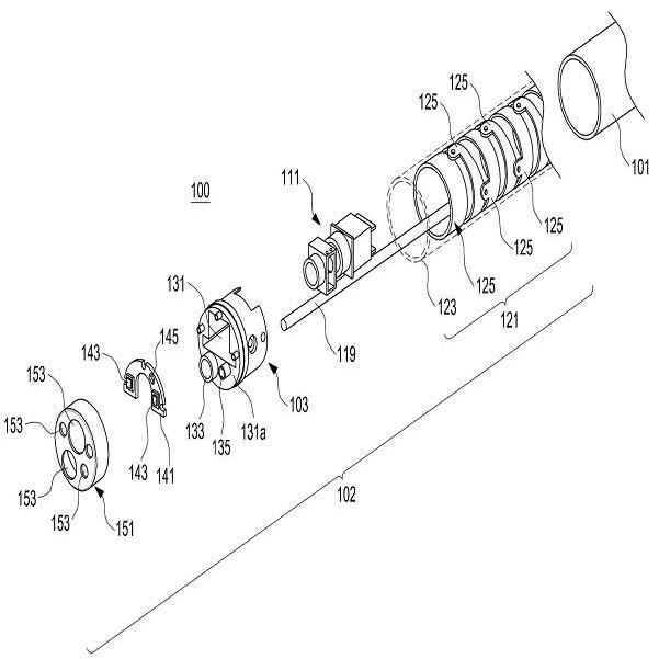
도 1 내지 도 5에 도시된 바와 같이, 본 발명의 바람직한 실시 예에 따른 내시경(100)은 삽입 튜브(101), 선단부 조립체(102) 및 냉각매체 튜브(119)를 구비하며, 냉각매체가 상기 선단부 조립체(102)를 냉각하게 된다. 이때, 상기 선단부 조립체(102)를 냉각하는 냉각매체는 상기 냉각매체 튜브(119)와 삽입 튜브(101) 중 하나를 통해 유입되고, 상기 냉각매체 튜브(119)와 삽입 튜브(101) 중 다른 하나를 통해 배출된다. As shown in Figures 1 to 5, the
상기 내시경(100)은 인체의 내부로 삽입되므로, 환자의 장기를 따라 이동할 수 있도록 유연성을 가지고 있다. 상기 선단부 조립체(102)는 상기 삽입 튜브(101)의 단부에 결합되며, 이미지 센서(111), 광원(143) 등이 장착된 선단부 몸체(103)와 관절부 조립체(joint assembly)(121)를 포함한다. 상기 관절부 조립체(121)는 다양한 방향으로 굴곡을 이룰 수 있게 변형 가능하며, 이는 내시경 장비의 운용자, 즉, 의사의 조작에 의해 이루어진다. 상기 냉각매체 튜브(119)는 상기 선단부 조립체(102), 더 구체적으로는 상기 선단부 몸체(103)에 연결되어 냉각매체를 상기 선단부 몸체(103)까지 공급하거나, 상기 선단부 몸체(103) 주위의 냉각매체를 배출하는 유로를 제공하게 된다. Since the
도 17을 더 참조하면, 상기 관절부 조립체(121)는 다수의 관절 부재(125)들이 서로에 대하여 회동 가능한 상태로 직렬로 연결되어 있다. 상기 관절 부재(125)들의 회동에 따라 상기 관절부 조립체(121)가 다양한 방향으로 굴곡을 이루게 변형될 수 있으며, 따라서 운용자는 상기 내시경(100)을 삽입하면서 내시경 선단부의 진행 방향을 조절할 수 있게 된다. 도시되지는 않지만, 상기 삽입 튜브(101)의 내부에 배치된 와이어가 상기 관절부 조립체(121)와 연결되며, 운용자의 조작은 상기 와이어를 통해 상기 관절부 조립체(121)에 전달된다. 상기 관절부 조립체(121)는 인체의 내부로 삽입되므로, 보호 튜브(123)를 이용하여 상기 관절 부재(125)들을 감싸는 것이 바람직하다. 상기 보호 튜브(123)는 인체 내부에서 체액 등에 의해 상기 관절 부재(125) 및 상기 내시경(100)의 내부가 오염되는 것을 방지하며, 나아가서는, 상기 관절 부재(125)들이 인체의 내부 조직에 간섭되는 것을 방지하게 된다. 상기 보호 튜브(123)의 일단은 상기 삽입 튜브(101)와 결합하고, 타단은 상기 선단부 몸체(103)와 결합하게 된다. 즉, 상기 삽입 튜브(101)와 선단부 몸체(103) 사이에서 상기 보호 튜브(123)는 밀봉 구조를 제공하는 것이다. Referring to FIG. 17, the
상기 선단부 몸체(103)는 상기 관절부 조립체(121)의 단부, 더 구체적으로, 상기 보호 튜브(123)의 한 단부에 결합하며, 이미지 센서(111)와 광원(143)을 장착할 공간을 제공하게 된다. 도 6 내지 도 7을 더 참조하면, 상기 선단부 몸체(103)는 길이방향으로 관통하게 형성된 수용홀(131), 처치구(treatment hole)(133)와 분사구(nozzle)(135)를 구비한다. 또한, 상기 선단부 몸체(103)는 후면(131b)에 형성된 냉각 포트(137)를 구비한다. 상기 수용홀(131)은 상기 이미지 센서(111)를 수용하게 되며, 상기 처치구(133)와 분사구(135)는 내시경(100) 수술 등을 수행할 때, 수술용 나이프와 소독액 등을 상기 내시경(100)의 전방으로 배치, 공급할 수 있는 수단을 제공하게 된다. The
상기 냉각 포트(137)는 상기 냉각매체 튜브(119)에 연결된다. 도 8에서 도면부호 '139'로 지시된 바와 같이 상기 냉각 포트(137)와 상기 선단부 몸체(103)의 후면(131b) 사이는 적어도 부분적으로 개방됨으로써, 상기 냉각매체 튜브(119)를 통해 유입되는 냉각매체가 상기 선단부 몸체(103)의 주위로 분사된다. 상기 냉각매체 튜브(119)가 냉각매체를 배출하게 설계되었다면, 상기 삽입 튜브(101)를 통해 유입된 냉각매체가 상기 광원(143) 및 선단부 몸체(103)와 열 교환을 수행한 후 상기 냉각매체 튜브(119)를 통해 배출될 것이다. 이는, 도 3에 도시된 바와 같이, 인체의 외부, 또한, 상기 삽입 튜브(101)의 외부에 배치되는 공기 펌프(117)가 상기 냉각매체 튜브(119)에 연결됨으로써 가능하다. 상기 공기 펌프(117)가 작동함으로써, 상기 냉각매체 튜브(119)를 통해 냉각매체, 예를 들면, 외부 공기가 상기 내시경(100) 선단부로 유입되거나, 상기 내시경(100) 선단부에서 열 교환을 수행한 냉각매체를 배출된다. 상기 공기 펌프(117)와 연결된 상기 냉각매체 튜브(119)가 냉각매체를 배출시키는 구조라면, 실질적으로 상기 공기 펌프(117)로는 진공 펌프가 이용될 것이다. The cooling
한편, 도 9와 도 10에 도시된 바와 같이, 상기 냉각 포트(137)의 유로(137a)는 상기 선단부 몸체(103)의 전면(131a)까지 연장될 수 있다. 이 경우, 냉각매체는 상기 선단부 몸체(103)의 전면(131a)으로 공급되거나, 열 교환을 수행한 후 상기 선단부 몸체(103)의 전면(131a)에서 상기 유로(137a) 및 냉각 포트(137)와 냉각매체 튜브(119)를 순차적으로 지나 외부로 배출된다. Meanwhile, as illustrated in FIGS. 9 and 10, the
결국, 냉각매체는 상기 선단부 몸체(103)의 전면(131a) 및 후면(131b), 아울러, 상기 수용홀(131)의 내벽에 이르기까지 상기 내시경(100)의 내부에서 접촉할 수 있는 상기 선단부 몸체(103)의 전체 표면에서 열 교환을 수행하게 된다. 또한, 상기 광원(143)이 상기 선단부 몸체(103)에 배치되는데, 상기 수용홀(131) 또는 상기 유로(137a)를 통해 냉각매체가 상기 선단부 몸체(103)의 전면에 이르게 되어 상기 광원(143)과 직접 열 교환을 수행할 수도 있다. As a result, the cooling medium may be in contact with the
앞서 언급한 바와 같이, 상기 이미지 센서(111)는 상기 수용홀(131)에 수용된다. 도 11을 더 참조하면, 상기 광원(143)은 별도의 인쇄회로 기판(141)에 장착된 상태로 상기 선단부 몸체(103)에, 구체적으로, 상기 선단부 몸체(103)의 전면(131a)에 배치된다. 이때, 상기 인쇄회로 기판(141)은 금속 재질, 예를 들면, 알루미늄으로 제작되어 상기 광원(143)으로부터 발생된 열을 상기 선단부 몸체(103)로 전도할 수 있다. 상기 선단부 몸체(103) 또한 금속 재질, 예를 들면, 알루미늄 재질로 제작되어 상기 광원(143)으로부터 전달되는 열을 후면(131b) 방향으로 전도하게 된다. 상기 광원(143)은 상기 선단부 몸체(103)의 전면(131a)에서 상기 이미지 센서(111)의 양측에 각각 배치될 수 있다. 또한, 상기 인쇄회로 기판(141)은 가요성 인쇄회로 기판으로 이루어질 수 있다. 재질의 특성상, 가요성 인쇄회로 기판은 금속 재질의 기판에 비해 열 전도 계수는 낮지만, 두께가 금속 재질의 기판에 비해 얇기 때문에 금속 재질의 기판과 유사한 열 전도율을 제공할 수 있다. 즉, 상기 광원(143)과 선단부 몸체(103) 사이의 거리가 가까워지므로, 가요성 인쇄회로 기판의 열 전도 계수가 다소 낮더라도, 충분한 열 전도율을 확보할 수 있다. as I mentioned before, The
상기 인쇄회로 기판(141)에는 온도 감지 센서(145)가 더 장착될 수 있다. 상기 온도 감지 센서(145)는 상기 내시경(100)의 내부 온도, 특히, 상기 광원(143)의 작동에 따른 온도 변화를 검출하게 된다. 상기 온도 감지 센서(145)에서 상기 내시경(100)의 내부 온도가 인체 조직의 손상을 유발할 정도로 상승하는 것을 감지할 경우, 내시경 장비는 경고 신호를 발생하거나 상기 공기 펌프(117)를 제어하여 냉각매체의 유속을 증가시키게 된다. 상기 내시경(100)의 내부 온도가 안전한 범위 내에 있음을 상기 온도 감지 센서(145)가 감지하면, 내시경 장비는 다시 상기 공기 펌프(117)를 제어하여 냉각매체의 유속을 낮출 수 있다. The
상기 선단부 몸체(103)에는 덮개 부재(cap member)(151)가 제공되어, 상기 인쇄회로 기판(141) 및 광원(143), 이미지 센서(111) 등을 보호하게 된다. 즉, 인체의 내부에서 체액 등에 의해 상기 인쇄회로 기판(141) 등이 오염되는 것을 방지하게 된다. 다만, 상기 이미지 센서(111)의 촬영 경로, 상기 광원(143)의 조명을 제공하기 위한 경로, 상기 처치구(133) 및 분사구(135)가 배치되는 경로를 제공하기 위해, 상기 덮개 부재(151)에는 다수의 개구(153)들이 형성될 수 있다. A
선단부 몸체를 금속 재질로 제작하고 광원이 장착된 인쇄회로 기판 또한 금속 재질로 제작한 본 발명에 따른 내시경과, 인쇄회로 기판은 통상적인 유전체 기판으로 제작한 내시경에 대하여 광원이 작동할 때의 온도 분포를 측정해 보았다. 본 발명에 따른 내시경의 경우, 광원이 작동할 때 선단부, 더 구체적으로 광원에서의 최고 온도가 섭씨 68.11도 정도였고, 선단부로부터 멀어질수록 내시경의 온도 분포가 점차 낮아져 상온에 근접함을 확인할 수 있었다. 반면에, 통상적인 유전체 기판에 광원을 배치하고 선단부 몸체에 장착한 경우, 선단부의 최고 온도는 섭씨 542.7도에 이르렀다. 더욱이, 통상적인 유전체 기판에 광원을 배치하고 선단부 몸체에 장착한 내시경에서는 유전체 기판의 후방, 즉, 선단부 몸체로부터 상온에 근접한 온도 분포를 보이고 있었다. 결과적으로, 즉, 통상적인 인쇄회로 기판을 사용할 경우, 광원으로부터 발생된 열이 확산되지 못하고, 광원에만 집중되는 것이다. 광원에만 열이 집중될 경우, 지나치게 높아진 온도로 인해 인체 조직이 손상될 수 있음을 앞서 언급한 바 있다. Temperature distribution when the light source is operated with respect to the endoscope according to the present invention, the end body is made of a metal material and the light source is equipped with a printed circuit board also made of a metal material, and the printed circuit board is an endoscope made of a conventional dielectric substrate Was measured. In the case of the endoscope according to the present invention, when the light source is operated, the maximum temperature at the tip, more specifically, the light source was about 68.11 degrees Celsius, and as the distance from the tip was reduced, the temperature distribution of the endoscope gradually decreased to approach room temperature. . On the other hand, when the light source is placed on a conventional dielectric substrate and mounted on the tip body, the maximum temperature of the tip reaches 542.7 degrees Celsius. Moreover, the endoscope placed with a light source on a conventional dielectric substrate and mounted on the tip body showed a temperature distribution close to room temperature from the rear of the dielectric substrate, that is, from the tip body. As a result, that is, when using a conventional printed circuit board, heat generated from the light source is not diffused and is concentrated only on the light source. It has been mentioned previously that if heat is concentrated only in a light source, excessively high temperature may damage human tissue.
한편, 도 12와 도 13에 도시된 바와 같이, 상기 광원(143)은 상기 선단부 몸체(103)의 전면(131a)에 직접 장착될 수 있다. 다만, 상기 선단부 몸체(103) 또한 금속 재질로 제작되므로, 상기 선단부 몸체(103)의 전면(131a)에 절연물질, 예를 들면, 세라믹으로 코팅하는 것이 바람직하다. 상기 광원(143)에 연결되는 전극(141b)은 절연물질로 형성된 코팅층(141a) 상에 인쇄회로 패턴을 형성함으로써 제공할 수 있다. 절연물질로 형성된 상기 코팅층(141a)은, 가요성 인쇄회로 기판과 마찬가지로, 상기 광원(143)과 선단부 몸체(103) 사이의 간격을 좁혀 열 전도율을 높일 수 있다. 또한, 상기 코팅층(141a)을 세라믹으로 형성하는 경우, 세라믹의 열 전도 계수가 가요성 인쇄회로 기판보다 높아 열 전도율을 높일 수 있게 된다. 12 and 13, the
또한, 상기 선단부 몸체(103)나 광원(143)이 더 넓은 면적에서 냉각매체와 접촉한다면, 열 전도율, 다시 말해 방열, 냉각 효과는 더 높아지게 된다. 도 14 내지 도 16은 상기 선단부 몸체(103)와 냉각매체의 접촉 면적을 넓히기 위해, 상기 선단부 몸체(103)에 방열 핀(heat radiating fin)을 형성한 구성들을 도시하고 있다. 각각에 도시된 방열 핀은 각각 사각 홈(139a), V-자 형상 홈(139b), U-자 형상 홈(139c)들을 사이에 배치된 구성이다. 상기 방열 핀들을 형성함으로써, 앞서 언급한 바와 같이, 상기 선단부 몸체(103)는 더 넓은 면적에서 냉각매체와 접촉하여 열 교환을 수행하게 된다. 상기 내시경(100)의 선단부 내부 공간이 허용하는 범위에서, 또한, 상기 내시경(100)을 조작함에 있어, 간섭되지 않는 범위에서, 상기 방열 핀의 높이를 더 높게 할수록 열 전도율이 더 높아질 것임은 자명하다. In addition, if the
후면 온도Tip Body
Rear temperature
Invention
Structure 1
Structure 2
배출 유로 방식Cooling water inlet and
Discharge channel
Structure 3
배출 유로 방식Air inlet and
Discharge channel
상기의 [표 1]은 선단부 몸체와 광원 등의 배치 구조는 동일한 조건에서, 서로 다른 방열 구조들의 작동에 따른 온도 분포를 측정한 결과를 기재하고 있다. 이러한 온도 분포의 측정은 섭씨 25도, 60%의 상대습도 조건에서 진행되었다. [Table 1] shows the results of measuring the temperature distribution according to the operation of the different heat dissipation structures under the same conditions in the arrangement of the tip body and the light source. The temperature distribution was measured at 25 degrees Celsius and 60% relative humidity.
상기의 [표 1]에서, 구조1은, 광원에 연결된 전기 전도체 자체를 방열, 냉각 구조로 활용한 것이며, 구조2와 구조3은 냉각매체를 유입하기 위한 유로와 배출하기 위한 유로를 각각 배치하되, 구조2는 냉각수를 냉각매체로, 구조3은 공기를 냉각매체로 이용한 것이다. [표 1]에서 나타나는 바와 같이, 냉각 전의 광원 온도는 모든 구조에서 유사하다. 하지만, 냉각 후, 즉, 냉각매체를 유입/순환시키는 경우, 다른 구조들과 다르게, 본 발명에 따른 구조의 내시경(100)은 광원(143)의 상기한 측정 조건의 상온에 근접하게 유지할 수 있었다.
In the above Table 1, Structure 1 utilizes the electric conductor itself connected to the light source as a heat dissipation and cooling structure, and Structures 2 and 3 respectively include flow paths for introducing a cooling medium and flow paths for discharge. In structure 2, cooling water is used as a cooling medium, and in structure 3, air is used as a cooling medium. As shown in Table 1, the light source temperature before cooling is similar in all structures. However, after cooling, that is, when the cooling medium is introduced / circulated, unlike the other structures, the
이상, 본 발명의 상세한 설명에서는 구체적인 실시 예에 관해서 설명하였으나, 본 발명의 범위에서 벗어나지 않는 한도 내에서 여러 가지 변형이 가능함은 당해 분야에서 통상의 지식을 가진 자에게 있어서 자명하다 할 것이다. In the foregoing detailed description of the present invention, specific embodiments have been described. However, it will be apparent to those skilled in the art that various modifications can be made without departing from the scope of the present invention.
100: 내시경 101: 삽입 튜브
111: 이미지 센서 119: 냉각매체 튜브
102: 선단부 조립체 121: 관절부 조립체
123: 보호 튜브 125: 관절 부재
103: 선단부 몸체 137: 냉각 포트
141: 인쇄회로 기판 141: 광원 100: endoscope 101: insertion tube
111: image sensor 119: cooling medium tube
102: tip assembly 121: joint assembly
123: protective tube 125: joint member
103: tip body 137: cooling port
141: printed circuit board 141: light source
Claims (21)
상기 삽입 튜브의 단부에 제공된 선단부 몸체와, 상기 선단부 몸체의 후면에 형성된 냉각 포트와, 상기 선단부 몸체의 후면에 형성된 적어도 하나의 방열 핀과, 상기 선단부 몸체를 상기 삽입 튜브로 연결하는 관절부 조립체를 포함하는 선단부 조립체; 및
상기 삽입 튜브의 내부에 제공되며 상기 냉각 포트에 연결되어 상기 선단부 몸체의 주위로 냉각 매체를 공급하거나, 상기 선단부 몸체와 열교환을 수행한 후의 냉각 매체를 배출하는 냉각매체 튜브를 구비하고,
상기 선단부 몸체의 후면과 상기 냉각 포트 사이의 공간 일부가 개방되고,
상기 삽입 튜브 자체와 냉각매체 튜브 중 어느 하나는 상기 선단부 조립체를 냉각하는 냉각 매체를 유입시켜 상기 선단부 몸체의 주위로 순환시키고, 상기 삽입 튜브 자체와 냉각매체 튜브 중 다른 하나는 상기 선단부 몸체의 주위를 순환한 냉각 매체를 상기 선단부 몸체로부터 배출시킴을 특징으로 하는 내시경.
An insertion tube having flexibility;
A distal end body provided at an end of the insertion tube, a cooling port formed at a rear side of the distal end body, at least one heat dissipation fin formed at a rear side of the distal end body, and a joint assembly connecting the distal end body to the insertion tube; A tip assembly; And
A cooling medium tube provided inside the insertion tube and connected to the cooling port to supply a cooling medium to the periphery of the tip body or to discharge the cooling medium after performing heat exchange with the tip body;
A portion of the space between the rear of the tip body and the cooling port is opened,
One of the insertion tube itself and the cooling medium tube introduces a cooling medium for cooling the tip assembly to circulate around the tip body, and the other of the insertion tube itself and the cooling medium tube is around the tip body. An endoscope, characterized in that for discharging the circulated cooling medium from the tip body.
상기 냉각매체 튜브에 연결된 공기 펌프를 더 구비하고,
상기 공기 펌프가 작동함에 따라 상기 냉각매체를 통해 외부 공기를 상기 선단부 조립체로 유입하거나, 상기 선단부 조립체 주위의 공기를 배출함을 특징으로 하는 내시경.
According to claim 1,
Further comprising an air pump connected to the cooling medium tube,
As the air pump operates, the endoscope is characterized in that the external air is introduced into the tip assembly through the cooling medium, or the air around the tip assembly is discharged.
상기 선단부 조립체는 상기 관절부 조립체를 감싸게 제공되는 보호 튜브를 더 구비함을 특징으로 하는 내시경.
According to claim 1,
The tip end assembly further comprises a protective tube provided to surround the joint assembly.
The endoscope according to claim 1, wherein the cooling port is connected to the front surface of the front end body through the front end body and the cooling medium is supplied to the front side of the front end body.
상기 선단부 몸체에 제공되는 광원(light source)을 더 구비하고,
상기 광원에서 발생하는 열이 상기 선단부 몸체로 전도되며, 상기 냉각매체 튜브 또는 삽입 튜브를 통해 공급된 냉각 매체는 상기 광원 및 선단부 몸체와 열 교환을 수행함을 특징으로 하는 내시경.
The method of claim 1, wherein the front end assembly,
Further provided with a light source (light source) provided in the tip body,
And heat generated from the light source is conducted to the tip body, and the cooling medium supplied through the cooling medium tube or the insertion tube performs heat exchange with the light source and the tip body.
상기 선단부 조립체는 상기 선단부 몸체의 전면에 장착되는 인쇄회로 기판을 더 구비하고,
상기 광원은 상기 인쇄회로 기판에 장착됨을 특징으로 하는 내시경.
The method of claim 8,
The tip assembly further includes a printed circuit board mounted on the front surface of the tip body,
The light source is endoscope, characterized in that mounted to the printed circuit board.
The endoscope of claim 10, wherein the printed circuit board is made of metal or a flexible printed circuit board.
상기 선단부 몸체의 전면에 형성되는 절연층; 및
상기 절연층 상에 형성된 인쇄회로 패턴을 더 구비하고,
상기 광원은 상기 인쇄회로 패턴 상에 장착됨을 특징으로 하는 내시경.
The method of claim 8, wherein the tip assembly,
An insulation layer formed on the front surface of the tip body; And
Further comprising a printed circuit pattern formed on the insulating layer,
The light source is endoscope, characterized in that mounted on the printed circuit pattern.
상기 선단부 조립체는 상기 선단부 몸체에 장착되는 온도 감지 센서를 더 구비함을 특징으로 하는 내시경.
The method of claim 8,
The distal end assembly further comprises a temperature sensor mounted on the distal end body.
상기 선단부 조립체는 상기 선단부 몸체의 전면으로 배치되는 이미지 센서를 더 구비하고,
복수의 상기 광원이 상기 선단부 몸체의 전면에서 상기 이미지 센서의 주위에 배치됨을 특징으로 하는 내시경.
The method of claim 8,
The tip assembly further includes an image sensor disposed in front of the tip body,
And the plurality of light sources are disposed around the image sensor in front of the tip body.
상기 선단부 조립체는 상기 선단부 조립체의 길이방향을 따라 상기 선단부 몸체를 관통하게 형성된 수용홀을 더 구비하고,
상기 이미지 센서가 상기 수용홀 내에 장착됨을 특징으로 하는 내시경.
The method of claim 14,
The tip end assembly further includes a receiving hole formed to penetrate the tip end body in a longitudinal direction of the tip end assembly.
Endoscope, characterized in that the image sensor is mounted in the receiving hole.
상기 삽입 튜브의 단부에 제공된 선단부 몸체와, 상기 선단부 몸체의 후면에 형성된 냉각 포트와, 상기 선단부 몸체의 후면에 형성된 적어도 하나의 방열 핀과, 상기 선단부 몸체를 상기 삽입 튜브로 연결하는 관절부 조립체를 포함하는 선단부 조립체;
상기 삽입 튜브의 내부에 제공되며 상기 냉각 포트에 연결되어 상기 선단부 몸체의 주위로 냉각 배체를 공급하거나, 상기 선단부 몸체와 열교환을 수행한 후의 냉각 매체를 배출하는 냉각매체 튜브; 및
상기 선단부 몸체에 제공되는 광원을 구비하고,
상기 선단부 몸체의 후면과 상기 냉각 포트 사이의 공간 일부가 개방되고,
상기 삽입 튜브 자체와 냉각매체 튜브 중 어느 하나가 상기 선단부 몸체 및 광원을 냉각하는 냉각 매체를 유입시켜 상기 선단부 몸체의 주위로 순환시키고, 상기 삽입 튜브 자체와 냉각매체 튜브 중 다른 하나가 상기 선단부 몸체의 주위를 순환한 냉각 매체를 상기 선단부 몸체로부터 배출시킴을 특징으로 하는 내시경.
An insertion tube having flexibility;
A distal end body provided at an end of the insertion tube, a cooling port formed at a rear side of the distal end body, at least one heat dissipation fin formed at a rear side of the distal end body, and a joint assembly connecting the distal end body to the insertion tube; A tip assembly;
A cooling medium tube provided inside the insertion tube and connected to the cooling port to supply cooling exhaust around the tip body or to discharge a cooling medium after performing heat exchange with the tip body; And
A light source provided to the tip body;
A portion of the space between the rear of the tip body and the cooling port is opened,
Any one of the insertion tube itself and the cooling medium tube introduces a cooling medium for cooling the tip body and the light source and circulates around the tip body, and the other of the insertion tube itself and the cooling medium tube is connected to the tip body. An endoscope characterized in that the cooling medium circulated around the discharge from the tip body.
18. The endoscope of claim 17, wherein the tip body is made of aluminum, and heat generated from the light source is conducted through the tip body.
상기 선단부 몸체의 전면에 배치되는 인쇄회로 기판을 더 구비하고,
상기 인쇄회로 기판은 금속 재질 또는 가요성 인쇄회로 기판이며, 상기 광원은 상기 인쇄회로 기판에 배치됨을 특징으로 하는 내시경.
The method of claim 17,
Further comprising a printed circuit board disposed on the front of the front end body,
The printed circuit board is a metal material or a flexible printed circuit board, the light source is disposed on the printed circuit board endoscope.
Priority Applications (2)
| Application Number | Priority Date | Filing Date | Title |
|---|---|---|---|
| KR1020120133099A KR102027251B1 (en) | 2012-11-22 | 2012-11-22 | Endoscope |
| US13/790,741 US9826895B2 (en) | 2012-11-22 | 2013-03-08 | Endoscope with single cooling medium tube introducing or discharging cooling medium |
Applications Claiming Priority (1)
| Application Number | Priority Date | Filing Date | Title |
|---|---|---|---|
| KR1020120133099A KR102027251B1 (en) | 2012-11-22 | 2012-11-22 | Endoscope |
Publications (2)
| Publication Number | Publication Date |
|---|---|
| KR20140065968A KR20140065968A (en) | 2014-05-30 |
| KR102027251B1 true KR102027251B1 (en) | 2019-10-01 |
Family
ID=50728579
Family Applications (1)
| Application Number | Title | Priority Date | Filing Date |
|---|---|---|---|
| KR1020120133099A Expired - Fee Related KR102027251B1 (en) | 2012-11-22 | 2012-11-22 | Endoscope |
Country Status (2)
| Country | Link |
|---|---|
| US (1) | US9826895B2 (en) |
| KR (1) | KR102027251B1 (en) |
Families Citing this family (26)
| Publication number | Priority date | Publication date | Assignee | Title |
|---|---|---|---|---|
| US9901244B2 (en) * | 2009-06-18 | 2018-02-27 | Endochoice, Inc. | Circuit board assembly of a multiple viewing elements endoscope |
| US12220105B2 (en) * | 2010-06-16 | 2025-02-11 | Endochoice, Inc. | Circuit board assembly of a multiple viewing elements endoscope |
| US9375139B2 (en) * | 2010-07-29 | 2016-06-28 | Cannuflow, Inc. | Arthroscopic system |
| DE102013217500A1 (en) * | 2013-09-03 | 2015-03-05 | Olympus Winter & Ibe Gmbh | Endoscope and endoscope tip |
| USD757935S1 (en) * | 2014-02-06 | 2016-05-31 | Karl Storz Endoscopy-America, Inc. | Rotation wheel extension |
| JP6226804B2 (en) * | 2014-04-07 | 2017-11-08 | オリンパス株式会社 | Endoscope anti-fogging unit and endoscope system |
| US10952600B2 (en) * | 2014-07-10 | 2021-03-23 | Covidien Lp | Endoscope system |
| DE102017102178B3 (en) | 2017-02-03 | 2018-06-14 | Invendo Medical Gmbh | Endoscope and manufacturing method for a camera board with longitudinal pins with three functions |
| CN108175366A (en) * | 2017-12-29 | 2018-06-19 | 上海安翰医疗技术有限公司 | Cooling device and the endoscope with the cooling device |
| CN112955099B (en) * | 2018-07-27 | 2024-04-26 | 雷森斯医疗有限公司 | Medical cooling device and cooling method using the same |
| GB2576039B (en) * | 2018-08-02 | 2021-01-06 | Ip2Ipo Innovations Ltd | A joint |
| EP3613327A1 (en) | 2018-08-24 | 2020-02-26 | Ambu A/S | A tip part for a vision device |
| CN109124546B (en) * | 2018-08-31 | 2021-10-22 | 上海澳华内镜股份有限公司 | Cooling system for endoscope lighting and endoscope |
| US11998284B2 (en) * | 2018-12-07 | 2024-06-04 | Acclarent, Inc. | Articulating guide with integral position sensor |
| EP3979894A4 (en) * | 2019-06-05 | 2023-06-07 | 270 Surgical Ltd. | HEAT REMOVAL INFRASTRUCTURE FOR ENDOSCOPES |
| US11794389B2 (en) * | 2019-09-06 | 2023-10-24 | Ambu A/S | Tip part assembly for an endoscope |
| USD958747S1 (en) * | 2020-05-21 | 2022-07-26 | Shanghai Microport Medbot (Group) Co., Ltd. | Coupler |
| USD959378S1 (en) * | 2020-05-21 | 2022-08-02 | Shanghai Microport Medbot (Group) Co., Ltd. | Coupler |
| USD959379S1 (en) * | 2020-05-21 | 2022-08-02 | Shanghai Microport Medbot (Group) Co., Ltd. | Coupler |
| GB2595894A (en) * | 2020-06-10 | 2021-12-15 | Memic Innovative Surgery Ltd | Heat removal loop in a mechanical arm of a surgical apparatus |
| CN111887799B (en) * | 2020-08-31 | 2025-06-13 | 深圳市精锋医疗科技股份有限公司 | Electronic endoscopes and surgical robots |
| US20220346639A1 (en) * | 2021-04-30 | 2022-11-03 | Vicarious Surgical Inc. | Systems and methods for thermal management of imaging devices |
| CN116172498A (en) * | 2023-03-07 | 2023-05-30 | 飞依诺科技股份有限公司 | Tip structure of endoscope and endoscope having same |
| DE102023124088A1 (en) * | 2023-09-07 | 2025-03-13 | Karl Storz Se & Co. Kg | Medical imaging device, in particular endoscope or exoscope, and method for controlling and/or regulating a medical imaging device |
| USD1080870S1 (en) * | 2025-01-17 | 2025-06-24 | Acoath Technology Co., Limited | Combined endoscope with light |
| USD1087340S1 (en) * | 2025-01-18 | 2025-08-05 | Acoath Technology Co., Limited | Dual lens endoscope |
Citations (1)
| Publication number | Priority date | Publication date | Assignee | Title |
|---|---|---|---|---|
| US20050075538A1 (en) * | 2003-04-01 | 2005-04-07 | Banik Michael S. | Single use endoscopic imaging system |
Family Cites Families (23)
| Publication number | Priority date | Publication date | Assignee | Title |
|---|---|---|---|---|
| JP3875505B2 (en) | 2001-03-29 | 2007-01-31 | オリンパス株式会社 | Imaging device |
| US6480389B1 (en) * | 2002-01-04 | 2002-11-12 | Opto Tech Corporation | Heat dissipation structure for solid-state light emitting device package |
| DE60301284T2 (en) * | 2002-02-25 | 2006-06-01 | Olympus Corporation | Endoscope with cooling device |
| US7578786B2 (en) * | 2003-04-01 | 2009-08-25 | Boston Scientific Scimed, Inc. | Video endoscope |
| WO2006039511A2 (en) * | 2004-09-30 | 2006-04-13 | Boston Scientific Scimed, Inc. | System and method of obstruction removal |
| DE102005030861A1 (en) | 2005-07-01 | 2007-01-04 | Invendo Medical Gmbh | Cooling device for electronic components, preferably an endoscope |
| JP5030399B2 (en) | 2005-07-04 | 2012-09-19 | オリンパスメディカルシステムズ株式会社 | Endoscope |
| US20100177519A1 (en) * | 2006-01-23 | 2010-07-15 | Schlitz Daniel J | Electro-hydrodynamic gas flow led cooling system |
| US7955255B2 (en) * | 2006-04-20 | 2011-06-07 | Boston Scientific Scimed, Inc. | Imaging assembly with transparent distal cap |
| US20070247867A1 (en) * | 2006-04-21 | 2007-10-25 | Sunoptic Technologies Llc | Portable LED Light Source for an Endoscope or Boroscope |
| JP2008011992A (en) * | 2006-07-04 | 2008-01-24 | Olympus Medical Systems Corp | Endoscope |
| US8498695B2 (en) * | 2006-12-22 | 2013-07-30 | Novadaq Technologies Inc. | Imaging system with a single color image sensor for simultaneous fluorescence and color video endoscopy |
| JP5075437B2 (en) * | 2007-03-19 | 2012-11-21 | オリンパス株式会社 | Endoscope cooling device and endoscope device |
| US8152715B2 (en) * | 2007-09-14 | 2012-04-10 | Optim, Incorporated | Endoscope with internal light source and power supply |
| JP2009160075A (en) | 2007-12-28 | 2009-07-23 | Olympus Corp | Endoscope system |
| JP2010022815A (en) * | 2008-06-18 | 2010-02-04 | Olympus Corp | Endoscope apparatus |
| JP2010088661A (en) * | 2008-10-08 | 2010-04-22 | Olympus Corp | Endoscope |
| US8409176B2 (en) * | 2008-12-02 | 2013-04-02 | Biolitec Pharma Marketing Ltd | Method and device for laser lithotripsy |
| DE102009049683B4 (en) | 2009-10-19 | 2016-06-09 | Richard Wolf Gmbh | Endoscopic instrument |
| DE102010024003A1 (en) * | 2010-06-11 | 2011-12-15 | Karl Storz Gmbh & Co. Kg | endoscope |
| JP5534997B2 (en) * | 2010-08-03 | 2014-07-02 | 富士フイルム株式会社 | Electronic endoscope system |
| CA2749832C (en) * | 2010-08-30 | 2016-04-26 | Ushio Denki Kabushiki Kaisha | Light source unit |
| DE102011055526A1 (en) * | 2011-11-18 | 2013-05-23 | Invendo Medical Gmbh | Medical endoscope with cooling device for built-in electrical components |
-
2012
- 2012-11-22 KR KR1020120133099A patent/KR102027251B1/en not_active Expired - Fee Related
-
2013
- 2013-03-08 US US13/790,741 patent/US9826895B2/en not_active Expired - Fee Related
Patent Citations (1)
| Publication number | Priority date | Publication date | Assignee | Title |
|---|---|---|---|---|
| US20050075538A1 (en) * | 2003-04-01 | 2005-04-07 | Banik Michael S. | Single use endoscopic imaging system |
Also Published As
| Publication number | Publication date |
|---|---|
| US20140142384A1 (en) | 2014-05-22 |
| US9826895B2 (en) | 2017-11-28 |
| KR20140065968A (en) | 2014-05-30 |
Similar Documents
| Publication | Publication Date | Title |
|---|---|---|
| KR102027251B1 (en) | Endoscope | |
| US20190053941A1 (en) | System for reducing localised fatty masses by means of cold application, applicator for such a system and non-invasive treatment method for reducing fats by means of cold application | |
| US10111577B2 (en) | Endoscopic instrument with an LED illumination module | |
| US7789883B2 (en) | Curative treatment system, curative treatment device, and treatment method for living tissue using energy | |
| JP6147466B2 (en) | Catheter with liquid-cooled control handle | |
| BR112020004831B1 (en) | CATHETER FOR ULTRASOUND TREATMENT WITH SOLID STATE COOLING | |
| WO2007125637A1 (en) | Radio frequency medical treatment device and system and usage method thereof | |
| US6733442B1 (en) | Accessory for surgical instrument | |
| KR20190004691A (en) | Transmission device with coaxial cable, apparatus and method comprising the device | |
| JP2024528646A (en) | Robot-assisted electrosurgery device | |
| CN114615944A (en) | Introducer for electrosurgical instrument | |
| JP2022535732A (en) | Heat removal infrastructure for endoscopy | |
| AU2016265602B2 (en) | Device for resecting an organ in a cavity of a body | |
| KR102339007B1 (en) | Endoscope having Bending Section with Heating Function | |
| US8734434B2 (en) | Skin cooling for a dermatologic treatment procedure | |
| WO2015046654A1 (en) | System for circulating ultrasound transfer medium in high-intensity focused ultrasound treatment device and method for circulating same | |
| JP7420556B2 (en) | Device for increasing the heat dissipation capacity of medical equipment | |
| JPH1132985A (en) | Electronic endoscope | |
| CN209712856U (en) | A laparoscopic light source cooling mechanism | |
| KR102266199B1 (en) | Rigidity tunable mechanism and endoscope utilizing thermoelectric modules and phase changeable materials at low temperature | |
| CN219763294U (en) | Laparoscopic anti-fog device based on air heating internal circulation | |
| CN222398819U (en) | Probe device, host and probe system | |
| US12533017B2 (en) | Heat removal loop in a mechanical arm of a surgical apparatus | |
| JP5509003B2 (en) | Endoscope | |
| JP2012115520A (en) | Endoscope |
Legal Events
| Date | Code | Title | Description |
|---|---|---|---|
| PA0109 | Patent application |
St.27 status event code: A-0-1-A10-A12-nap-PA0109 |
|
| PG1501 | Laying open of application |
St.27 status event code: A-1-1-Q10-Q12-nap-PG1501 |
|
| A201 | Request for examination | ||
| PA0201 | Request for examination |
St.27 status event code: A-1-2-D10-D11-exm-PA0201 |
|
| E902 | Notification of reason for refusal | ||
| PE0902 | Notice of grounds for rejection |
St.27 status event code: A-1-2-D10-D21-exm-PE0902 |
|
| E13-X000 | Pre-grant limitation requested |
St.27 status event code: A-2-3-E10-E13-lim-X000 |
|
| P11-X000 | Amendment of application requested |
St.27 status event code: A-2-2-P10-P11-nap-X000 |
|
| P13-X000 | Application amended |
St.27 status event code: A-2-2-P10-P13-nap-X000 |
|
| E701 | Decision to grant or registration of patent right | ||
| PE0701 | Decision of registration |
St.27 status event code: A-1-2-D10-D22-exm-PE0701 |
|
| GRNT | Written decision to grant | ||
| PR0701 | Registration of establishment |
St.27 status event code: A-2-4-F10-F11-exm-PR0701 |
|
| PR1002 | Payment of registration fee |
St.27 status event code: A-2-2-U10-U11-oth-PR1002 Fee payment year number: 1 |
|
| PG1601 | Publication of registration |
St.27 status event code: A-4-4-Q10-Q13-nap-PG1601 |
|
| PC1903 | Unpaid annual fee |
St.27 status event code: A-4-4-U10-U13-oth-PC1903 Not in force date: 20220926 Payment event data comment text: Termination Category : DEFAULT_OF_REGISTRATION_FEE |
|
| PC1903 | Unpaid annual fee |
St.27 status event code: N-4-6-H10-H13-oth-PC1903 Ip right cessation event data comment text: Termination Category : DEFAULT_OF_REGISTRATION_FEE Not in force date: 20220926 |