KR101996617B1 - Integrated cartridge - Google Patents
Integrated cartridge Download PDFInfo
- Publication number
- KR101996617B1 KR101996617B1 KR1020180121123A KR20180121123A KR101996617B1 KR 101996617 B1 KR101996617 B1 KR 101996617B1 KR 1020180121123 A KR1020180121123 A KR 1020180121123A KR 20180121123 A KR20180121123 A KR 20180121123A KR 101996617 B1 KR101996617 B1 KR 101996617B1
- Authority
- KR
- South Korea
- Prior art keywords
- unit
- hole
- air discharge
- supply unit
- holes
- Prior art date
- Legal status (The legal status is an assumption and is not a legal conclusion. Google has not performed a legal analysis and makes no representation as to the accuracy of the status listed.)
- Active
Links
- 238000010828 elution Methods 0.000 claims abstract description 15
- 238000007599 discharging Methods 0.000 claims abstract description 5
- 239000004480 active ingredient Substances 0.000 claims description 26
- 239000000463 material Substances 0.000 claims description 12
- 239000011247 coating layer Substances 0.000 claims description 11
- 239000004615 ingredient Substances 0.000 claims description 7
- 230000005484 gravity Effects 0.000 claims description 4
- 230000002209 hydrophobic effect Effects 0.000 claims description 4
- 230000002401 inhibitory effect Effects 0.000 claims description 2
- 239000012530 fluid Substances 0.000 abstract description 33
- 238000012546 transfer Methods 0.000 abstract description 3
- 230000004308 accommodation Effects 0.000 abstract 2
- 239000000523 sample Substances 0.000 description 10
- 230000008878 coupling Effects 0.000 description 7
- 238000010168 coupling process Methods 0.000 description 7
- 238000005859 coupling reaction Methods 0.000 description 7
- 108020004707 nucleic acids Proteins 0.000 description 6
- 150000007523 nucleic acids Chemical class 0.000 description 6
- 102000039446 nucleic acids Human genes 0.000 description 6
- 238000000034 method Methods 0.000 description 5
- 238000007781 pre-processing Methods 0.000 description 5
- 230000003321 amplification Effects 0.000 description 4
- 238000002405 diagnostic procedure Methods 0.000 description 4
- 238000003199 nucleic acid amplification method Methods 0.000 description 4
- 238000003753 real-time PCR Methods 0.000 description 4
- 239000013076 target substance Substances 0.000 description 4
- 238000001514 detection method Methods 0.000 description 3
- 108090000623 proteins and genes Proteins 0.000 description 3
- 238000012864 cross contamination Methods 0.000 description 2
- 201000010099 disease Diseases 0.000 description 2
- 208000037265 diseases, disorders, signs and symptoms Diseases 0.000 description 2
- 230000002068 genetic effect Effects 0.000 description 2
- 208000015181 infectious disease Diseases 0.000 description 2
- 230000035772 mutation Effects 0.000 description 2
- 238000012360 testing method Methods 0.000 description 2
- XLYOFNOQVPJJNP-UHFFFAOYSA-N water Substances O XLYOFNOQVPJJNP-UHFFFAOYSA-N 0.000 description 2
- 238000003745 diagnosis Methods 0.000 description 1
- 239000003989 dielectric material Substances 0.000 description 1
- 239000003814 drug Substances 0.000 description 1
- 229940079593 drug Drugs 0.000 description 1
- 238000013399 early diagnosis Methods 0.000 description 1
- 238000012986 modification Methods 0.000 description 1
- 230000004048 modification Effects 0.000 description 1
- 239000002773 nucleotide Substances 0.000 description 1
- 125000003729 nucleotide group Chemical group 0.000 description 1
- 238000003752 polymerase chain reaction Methods 0.000 description 1
- 238000012545 processing Methods 0.000 description 1
- 238000004451 qualitative analysis Methods 0.000 description 1
- 238000004445 quantitative analysis Methods 0.000 description 1
- 230000035945 sensitivity Effects 0.000 description 1
- 239000000126 substance Substances 0.000 description 1
Images


Classifications
-
- B—PERFORMING OPERATIONS; TRANSPORTING
- B01—PHYSICAL OR CHEMICAL PROCESSES OR APPARATUS IN GENERAL
- B01L—CHEMICAL OR PHYSICAL LABORATORY APPARATUS FOR GENERAL USE
- B01L3/00—Containers or dishes for laboratory use, e.g. laboratory glassware; Droppers
- B01L3/50—Containers for the purpose of retaining a material to be analysed, e.g. test tubes
- B01L3/502—Containers for the purpose of retaining a material to be analysed, e.g. test tubes with fluid transport, e.g. in multi-compartment structures
-
- B—PERFORMING OPERATIONS; TRANSPORTING
- B01—PHYSICAL OR CHEMICAL PROCESSES OR APPARATUS IN GENERAL
- B01L—CHEMICAL OR PHYSICAL LABORATORY APPARATUS FOR GENERAL USE
- B01L3/00—Containers or dishes for laboratory use, e.g. laboratory glassware; Droppers
- B01L3/50—Containers for the purpose of retaining a material to be analysed, e.g. test tubes
- B01L3/508—Containers for the purpose of retaining a material to be analysed, e.g. test tubes rigid containers not provided for above
-
- B—PERFORMING OPERATIONS; TRANSPORTING
- B01—PHYSICAL OR CHEMICAL PROCESSES OR APPARATUS IN GENERAL
- B01L—CHEMICAL OR PHYSICAL LABORATORY APPARATUS FOR GENERAL USE
- B01L7/00—Heating or cooling apparatus; Heat insulating devices
- B01L7/52—Heating or cooling apparatus; Heat insulating devices with provision for submitting samples to a predetermined sequence of different temperatures, e.g. for treating nucleic acid samples
-
- G—PHYSICS
- G01—MEASURING; TESTING
- G01N—INVESTIGATING OR ANALYSING MATERIALS BY DETERMINING THEIR CHEMICAL OR PHYSICAL PROPERTIES
- G01N35/00—Automatic analysis not limited to methods or materials provided for in any single one of groups G01N1/00 - G01N33/00; Handling materials therefor
-
- B—PERFORMING OPERATIONS; TRANSPORTING
- B01—PHYSICAL OR CHEMICAL PROCESSES OR APPARATUS IN GENERAL
- B01L—CHEMICAL OR PHYSICAL LABORATORY APPARATUS FOR GENERAL USE
- B01L2200/00—Solutions for specific problems relating to chemical or physical laboratory apparatus
- B01L2200/06—Fluid handling related problems
- B01L2200/0647—Handling flowable solids, e.g. microscopic beads, cells, particles
-
- B—PERFORMING OPERATIONS; TRANSPORTING
- B01—PHYSICAL OR CHEMICAL PROCESSES OR APPARATUS IN GENERAL
- B01L—CHEMICAL OR PHYSICAL LABORATORY APPARATUS FOR GENERAL USE
- B01L2200/00—Solutions for specific problems relating to chemical or physical laboratory apparatus
- B01L2200/06—Fluid handling related problems
- B01L2200/0684—Venting, avoiding backpressure, avoid gas bubbles
-
- B—PERFORMING OPERATIONS; TRANSPORTING
- B01—PHYSICAL OR CHEMICAL PROCESSES OR APPARATUS IN GENERAL
- B01L—CHEMICAL OR PHYSICAL LABORATORY APPARATUS FOR GENERAL USE
- B01L2200/00—Solutions for specific problems relating to chemical or physical laboratory apparatus
- B01L2200/10—Integrating sample preparation and analysis in single entity, e.g. lab-on-a-chip concept
-
- B—PERFORMING OPERATIONS; TRANSPORTING
- B01—PHYSICAL OR CHEMICAL PROCESSES OR APPARATUS IN GENERAL
- B01L—CHEMICAL OR PHYSICAL LABORATORY APPARATUS FOR GENERAL USE
- B01L2200/00—Solutions for specific problems relating to chemical or physical laboratory apparatus
- B01L2200/14—Process control and prevention of errors
- B01L2200/141—Preventing contamination, tampering
-
- B—PERFORMING OPERATIONS; TRANSPORTING
- B01—PHYSICAL OR CHEMICAL PROCESSES OR APPARATUS IN GENERAL
- B01L—CHEMICAL OR PHYSICAL LABORATORY APPARATUS FOR GENERAL USE
- B01L2200/00—Solutions for specific problems relating to chemical or physical laboratory apparatus
- B01L2200/16—Reagents, handling or storing thereof
-
- B—PERFORMING OPERATIONS; TRANSPORTING
- B01—PHYSICAL OR CHEMICAL PROCESSES OR APPARATUS IN GENERAL
- B01L—CHEMICAL OR PHYSICAL LABORATORY APPARATUS FOR GENERAL USE
- B01L2300/00—Additional constructional details
- B01L2300/08—Geometry, shape and general structure
- B01L2300/0832—Geometry, shape and general structure cylindrical, tube shaped
-
- B—PERFORMING OPERATIONS; TRANSPORTING
- B01—PHYSICAL OR CHEMICAL PROCESSES OR APPARATUS IN GENERAL
- B01L—CHEMICAL OR PHYSICAL LABORATORY APPARATUS FOR GENERAL USE
- B01L2300/00—Additional constructional details
- B01L2300/08—Geometry, shape and general structure
- B01L2300/0861—Configuration of multiple channels and/or chambers in a single devices
- B01L2300/0864—Configuration of multiple channels and/or chambers in a single devices comprising only one inlet and multiple receiving wells, e.g. for separation, splitting
-
- B—PERFORMING OPERATIONS; TRANSPORTING
- B01—PHYSICAL OR CHEMICAL PROCESSES OR APPARATUS IN GENERAL
- B01L—CHEMICAL OR PHYSICAL LABORATORY APPARATUS FOR GENERAL USE
- B01L2300/00—Additional constructional details
- B01L2300/16—Surface properties and coatings
- B01L2300/161—Control and use of surface tension forces, e.g. hydrophobic, hydrophilic
-
- B—PERFORMING OPERATIONS; TRANSPORTING
- B01—PHYSICAL OR CHEMICAL PROCESSES OR APPARATUS IN GENERAL
- B01L—CHEMICAL OR PHYSICAL LABORATORY APPARATUS FOR GENERAL USE
- B01L2400/00—Moving or stopping fluids
- B01L2400/04—Moving fluids with specific forces or mechanical means
- B01L2400/0403—Moving fluids with specific forces or mechanical means specific forces
- B01L2400/0406—Moving fluids with specific forces or mechanical means specific forces capillary forces
-
- B—PERFORMING OPERATIONS; TRANSPORTING
- B01—PHYSICAL OR CHEMICAL PROCESSES OR APPARATUS IN GENERAL
- B01L—CHEMICAL OR PHYSICAL LABORATORY APPARATUS FOR GENERAL USE
- B01L2400/00—Moving or stopping fluids
- B01L2400/06—Valves, specific forms thereof
- B01L2400/0633—Valves, specific forms thereof with moving parts
- B01L2400/0644—Valves, specific forms thereof with moving parts rotary valves
-
- B—PERFORMING OPERATIONS; TRANSPORTING
- B01—PHYSICAL OR CHEMICAL PROCESSES OR APPARATUS IN GENERAL
- B01L—CHEMICAL OR PHYSICAL LABORATORY APPARATUS FOR GENERAL USE
- B01L2400/00—Moving or stopping fluids
- B01L2400/06—Valves, specific forms thereof
- B01L2400/0688—Valves, specific forms thereof surface tension valves, capillary stop, capillary break
Landscapes
- Health & Medical Sciences (AREA)
- Chemical & Material Sciences (AREA)
- General Health & Medical Sciences (AREA)
- Analytical Chemistry (AREA)
- Chemical Kinetics & Catalysis (AREA)
- Clinical Laboratory Science (AREA)
- Hematology (AREA)
- Biochemistry (AREA)
- Life Sciences & Earth Sciences (AREA)
- General Physics & Mathematics (AREA)
- Immunology (AREA)
- Pathology (AREA)
- Physics & Mathematics (AREA)
- Molecular Biology (AREA)
- Apparatus Associated With Microorganisms And Enzymes (AREA)
- Automatic Analysis And Handling Materials Therefor (AREA)
- Physical Or Chemical Processes And Apparatus (AREA)
Abstract
Description
본 발명은 일체형 카트리지에 관한 것으로, 보다 상세하게는, 대상 물질을 진단 또는 분석하기 위한 일체형 카트리지에 관한 것이다.The present invention relates to an integral type cartridge, and more particularly, to an integral type cartridge for diagnosing or analyzing a target substance.
분자 진단이란, 대상 물질의 유전자(DNA 또는 RNA)를 직접 분석하여 질병의 감염 여부, 염기서열 변이 또는 돌연변이를 밝혀내어, 질병의 조기 진단과 효율적인 치료를 가능하게 하는 진단 방법이다. 특히, 최근에는 질병의 감염 확인, 유전자 검사, 약물 유전학 검사 등 다양한 의학 분야에서 분자 진단법이 사용되고 있다.Molecular diagnosis is a diagnostic method that enables early diagnosis of disease and efficient treatment by directly analyzing the gene (DNA or RNA) of the target substance to identify the disease infection, nucleotide sequence mutation or mutation. In recent years, molecular diagnostic methods have been used in various medical fields such as infection detection, genetic testing, and drug genetic testing.
분자 진단법에는 다양한 검출 방법이 개발되어왔는데, 특히, 실시간 중합 효소 연쇄반응(realtime polymerase chain reaction)은 그 방법의 신속성, 편리함 및 검출의 민감성 등의 측면에서 최근에 보편적으로 널리 활용되는 추세이다. 실시간 중합 효소 연쇄반응은 일반적으로 검출 대상 물질 유전자와 특이적 상보 결합을 이루는 프로브(probe)를 사용하는데, 이러한 프로브에는 형광 물질(fluorescence molecule)이 결합되어 있다. 실시간 중합 효소 연쇄반응에서는 분석기기를 이용하여 이러한 형광 물질의 파장을 분석함으로써 대상 유전자에 대한 정성적/정량적인 분석이 이루어진다.A variety of detection methods have been developed for molecular diagnostics, and in particular real time polymerase chain reaction (PCR) has been widely used in recent years in terms of its rapidity, convenience, and sensitivity to detection. In real-time PCR, a probe that specifically binds to a target substance gene is used, and a fluorescence molecule is bound to the probe. In real-time PCR, qualitative / quantitative analysis of the target gene is performed by analyzing the wavelength of the fluorescent substance using an analyzer.
한편, 분자 진단법은 실시간 중합 효소 연쇄반응 등을 통해 대상 물질을 전처리한 후 전처리된 물질을 분석하게 되는데, 종래 기술에 따르면 분자 진단 과정에서 요구되는 다양한 과정을 수행하는 각각의 구성들로 인해 분자 진단용 장비의 크기가 크고 구조 역시 복잡한 문제점이 있었다.In the meantime, the molecular diagnostic method analyzes the pretreated material after pretreatment of the target substance through real-time PCR or the like. According to the prior art, due to the respective structures that perform various processes required in the molecular diagnostic process, The size of the equipment is large and the structure is also complicated.
따라서, 본 발명이 해결하고자 하는 과제는, 종래에 비해 간소화 및 소형화된 구조를 갖는 분자 진단용 유체 이송 장치를 제공하는 것이다.Therefore, a problem to be solved by the present invention is to provide a fluid conveying apparatus for molecular diagnostics having a simplified and miniaturized structure as compared with the prior art.
상기 목적을 달성하기 위한 본 발명의 일 측면에 따르면, 시료를 전처리하는 전처리부; 상기 전처리부에서 전처리된 상기 시료로부터 유효성분을 용출(elution)하는 용출부; 및 상기 유효성분을 수용하는 수용부; 를 포함하고, 상기 수용부는, 상기 용출부에서 배출되는 상기 유효성분을 공급하는 공급 유닛; 상기 공급 유닛으로부터 공급받은 상기 유효성분을 저장 및 증폭하며 관(pipe)이 형성되는 저장 유닛; 및 상기 저장 유닛의 상기 관에 있는 공기를 외부로 배출하는 공기 배출 유닛; 을 포함하는 일체형 카트리지가 제공된다.According to an aspect of the present invention, there is provided a plasma processing apparatus comprising: a pretreatment unit for pretreating a sample; An elution unit for eluting an effective component from the sample pretreated in the pretreatment unit; And an accommodating portion for accommodating the effective ingredient; Wherein the accommodating portion comprises: a supply unit for supplying the effective component discharged from the eluting portion; A storage unit for storing and amplifying the effective component supplied from the supply unit and forming a pipe; And an air discharge unit for discharging the air in the pipe of the storage unit to the outside; Is provided.
상기 공급 유닛과 상기 공기 배출 유닛에는 각각 홀이 형성되고, 상기 저장 유닛에 구비되는 상기 관의 양끝부에는 상기 공급 유닛과 상기 공기 배출 유닛에 형성된 홀과 마주보는 입력홀(hole) 및 출력홀(hole)이 각각 형성되고, 상기 공급 유닛에 형성된 홀과 상기 입력홀이 서로 만나면, 상기 관 내부로 상기 유효성분이 공급될 수 있다.Wherein the supply unit and the air discharge unit are respectively provided with holes, and both ends of the pipe provided in the storage unit are provided with an input hole and an output hole facing the hole formed in the supply unit and the air discharge unit, holes are formed in the supply unit, and when the holes formed in the supply unit and the input holes meet each other, the effective ingredient can be supplied into the tube.
상기 관에 상기 유효성분이 공급될 때, 상기 공기 배출 유닛에 형성된 홀과 상기 출력홀이 서로 만남으로써, 상기 공기 배출 유닛을 통해 상기 관 내부에 존재하는 공기가 외부로 배출될 수 있다.When the effective component is supplied to the pipe, the holes formed in the air discharge unit and the output hole meet with each other, so that air existing in the pipe through the air discharge unit can be discharged to the outside.
상기 저장 유닛의 상기 관 내에서 상기 유효성분은 모세관 힘(capillary force)에 의해 이송될 수 있다.The active component in the tube of the storage unit may be transported by a capillary force.
상기 저장 유닛의 상기 관의 내벽에는 상기 모세관 힘을 생성하기 위한 친수성 재질을 포함하는 코팅층이 형성될 수 있다.A coating layer including a hydrophilic material for generating the capillary force may be formed on the inner wall of the tube of the storage unit.
상기 공급 유닛의 상기 홀의 내벽에는 상기 모세관 힘을 생성하기 위한 친수성 재질을 포함하는 코팅층이 형성될 수 있다.A coating layer including a hydrophilic material for generating the capillary force may be formed on an inner wall of the hole of the supply unit.
상기 공기 배출 유닛의 상기 홀의 내벽에는 상기 모세관 힘의 생성을 억제하기 위한 소수성 재질을 포함하는 코팅층이 형성될 수 있다.A coating layer including a hydrophobic material for suppressing the generation of the capillary force may be formed on the inner wall of the hole of the air exhaust unit.
상기 공급 유닛에는 상기 홀이 하나 형성되고, 상기 저장 유닛에는 상기 관이 복수로 형성되며, 상기 공급 유닛의 홀이 상기 복수의 관들의 상기 입력홀을 만날 수 있도록 공급 유닛은 회전 가능하게 구비될 수 있다.Wherein the supply unit is formed with one hole, the storage unit has a plurality of the tubes, and the supply unit is rotatably provided so that the holes of the supply unit can meet the input holes of the plurality of tubes. have.
상기 공기 배출 유닛에는 상기 홀이 복수로 형성되고, 상기 저장 유닛에는 상기 관이 복수로 형성되며, 상기 공기 배출 유닛의 상기 홀이 상기 복수의 관에 각각 형성된 복수의 상기 출력홀 중 하나와 만날 수 있도록 상기 공기 배출 유닛은 회전 가능하게 구비될 수 있다.The air discharge unit may have a plurality of holes, and the storage unit may have a plurality of the tubes, and the holes of the air discharge unit may meet with one of the plurality of output holes formed in the plurality of tubes The air discharge unit may be rotatably installed.
상기 공기 배출 유닛에는 상기 복수의 관에 형성된 상기 출력홀과 동일한 개수의 홀이 형성될 수 있다.The air discharge unit may have the same number of holes as the output holes formed in the plurality of pipes.
상기 수용부는 상기 용출부의 하부에 구비됨으로써, 상기 용출부에서 배출된 상기 유효성분이 중력 또는 모세관 힘에 의해 상기 공급 유닛에 공급될 수 있다.The receiving portion is provided at a lower portion of the eluting portion, so that the effective ingredient discharged from the eluting portion can be supplied to the supplying unit by gravity or a capillary force.
본 발명에 따르면, 종래에 비해 간소화 및 소형화된 구조를 갖는 분자 진단용 유체 이송 장치를 제공할 수 있다.According to the present invention, it is possible to provide a molecular diagnostic fluid transfer device having a simplified and miniaturized structure as compared with the prior art.
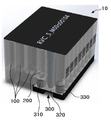
도 1은 본 발명에 따른 일체형 카트리지를 나타낸 사진이다.
도 2는 본 발명에 따른 일체형 카트리지의 공급 유닛을 도시한 사시도, 평면도, 저면도 및 측면도이다.
도 3은 본 발명에 따른 일체형 카트리지의 저장 유닛을 도시한 사시도이다.
도 4는 도 3의 A-A 선을 따라 본 발명에 따른 일체형 카트리지의 저장 유닛을 절단한 모습을 도시한 단면도이다.
도 5는 본 발명에 따른 일체형 카트리지의 공기 배출 유닛을 도시한 사시도, 평면도, 저면도 및 측면도이다.1 is a photograph showing an integral type cartridge according to the present invention.
2 is a perspective view, a plan view, a bottom view, and a side view showing a supply unit of the integral type cartridge according to the present invention.
3 is a perspective view showing a storage unit of the integral type cartridge according to the present invention.
FIG. 4 is a cross-sectional view illustrating a state in which the storage unit of the integral type cartridge according to the present invention is cut along the line AA in FIG.
5 is a perspective view, a plan view, a bottom view, and a side view of the air discharge unit of the integral type cartridge according to the present invention.
이하, 도면을 참고하여, 본 발명에 따른 일체형 카트리지의 구조를 설명하도록 한다.Hereinafter, the structure of the integral type cartridge according to the present invention will be described with reference to the drawings.
일체형 카트리지Integrated cartridge
도 1은 본 발명에 따른 일체형 카트리지를 나타낸 사진이다.1 is a photograph showing an integral type cartridge according to the present invention.
도 1에 도시된 바와 같이 본 발명에 따른 일체형 카트리지(10)는 시료를 전(前) 처리하는 전처리부(100)를 포함할 수 있다. 전처리부(100)에서 전처리되는 시료는 핵산(nucleic acid)을 포함하는 유전 물질을 포함할 수 있다. 전처리부(100)에서는 하기에서 살펴볼 바와 같이 시료로부터 핵산을 용출하기 전에 필요한 전처리 과정을 수행할 수 있다.As shown in FIG. 1, the integrated
또한, 일체형 카트리지(10)는 전처리부(100)에서 전처리된 시료로부터 유효성분을 용출(elution)하는 용출부(200)를 포함할 수 있다. 전처리된 시료가 핵산을 포함하는 경우, 용출부(200)에서는 시료로부터 핵산을 용출할 수 있다. 즉, 본 발명에 따른 유효성분은 핵산일 수 있다. 그러나, 본 발명에 따른 유효성분은 핵산에 제한되지 않는다. 한편, 용출부(200)에서 유효성분이 배출될 때에는 유효성분 뿐만 아니라 물도 함께 배출될 수 있다. 따라서, 본 명세서에서는 유효성분 및 물을 '유효성분을 포함한 유체'로 정의하도록 한다.In addition, the
한편, 일체형 카트리지(10)는 용출부(200)에서 용출된 유효성분을 포함한 유체를 수용하는 수용부(300)를 더 포함할 수 있다. 하기에서 살펴볼 바와 같이, 수용부에서는 유효성분을 포함한 유체가 저장될 수 있고, 수용부에 저장된 유효성분은 수용부 내에서 증폭됨으로써 유효성분의 수량이 증대될 수 있다. 이때, 도 1에 도시된 바와 같이 수용부(300)는 용출부(200)의 하부에 구비될 수 있다. 이 경우, 용출부(200)에서 배출된 유효성분을 포함한 유체는 중력 또는 하기에서 살펴볼 바와 같이 모세관 힘(capillary force)에 의해 수직 낙하하여 수용부(300)에 자연스럽게 공급될 수 있다.Meanwhile, the integrated
계속해서 도 1을 참고하면, 수용부(300)는 용출부(200)에서 배출된 유효성분을 포함한 유체를 공급하는 공급 유닛(310)을 포함할 수 있다. 특히, 공급 유닛(310)은 용출부(200)의 하부에 구비될 수 있다. 따라서, 용출부(200)에서 배출된 유효성분을 포함한 유체는 중력 또는 하기에서 살펴볼 바와 같이 모세관 힘(capillary force)에 의해 수직 낙하하여 공급 유닛(310)에 공급될 수 있다.1, the
또한, 수용부(300)는 공급 유닛(310)으로부터 공급받은 유효성분을 포함한 유체를 저장 및 증폭하는 저장 유닛(320)을 포함할 수 있고, 저장 유닛(320) 내부에 있는 공기를 외부로 배출하는 공기 배출 유닛(330)을 더 포함할 수 있다. 이하, 공급 유닛(310), 저장 유닛(320) 및 공기 배출 유닛(330)의 구조에 대해서 보다 상세하게 설명하도록 한다.The
도 2는 본 발명에 따른 일체형 카트리지의 공급 유닛을 도시한 사시도, 평면도, 저면도 및 측면도이다.2 is a perspective view, a plan view, a bottom view, and a side view showing a supply unit of the integral type cartridge according to the present invention.
도 2에 도시된 바와 같이 공급 유닛(310)에는 홀(312)이 형성될 수 있다. 공급 유닛(310)에 형성된 홀(312)은 용출부(200)에서 배출된 유효성분을 포함한 유체가 이동하는 경로를 제공할 수 있다. 도 2에 도시된 바와 같이 공급 유닛(310)에 형성된 홀(312)은 공급 유닛(310)의 상면에서부터 하면에까지 형성됨으로써 공급 유닛(310)의 두께 방향을 전체적으로 관통하도록 형성될 수 있다.As shown in FIG. 2, a
도 3은 본 발명에 따른 일체형 카트리지의 저장 유닛을 도시한 사시도이고, 도 4는 도 3의 A-A 선을 따라 본 발명에 따른 일체형 카트리지의 저장 유닛을 절단한 모습을 도시한 단면도이다.FIG. 3 is a perspective view showing a storage unit of the integral type cartridge according to the present invention, and FIG. 4 is a sectional view showing the storage unit of the integral type cartridge according to the present invention cut along the line A-A of FIG.
도 3 및 도 4에 도시된 바와 같이, 저장 유닛(320)에는 관(pipe)이 형성될 수 있다. 관(322)의 공급 유닛(310) 방향의 일끝부에는 공급 유닛(310)에 형성된 홀(312)과 마주보는 입력홀(322a)이 형성될 수 있다. 유효성분을 포함하는 유체는 용출부(200)로부터 공급 유닛(310)의 홀(312), 그리고, 관(322)의 입력홀(322a)을 통해 관(322) 내부에 공급될 수 있다. 즉, 본 발명에 따르면 공급 유닛(310)에 형성된 홀(312)과 관(322)의 입력홀(322a)이 서로 만나면, 관(322) 내부로 유효성분을 포함한 유체가 공급될 수 있다.As shown in FIGS. 3 and 4, a pipe may be formed in the
도 5는 본 발명에 따른 일체형 카트리지의 공기 배출 유닛을 도시한 사시도, 평면도, 저면도 및 측면도이다.5 is a perspective view, a plan view, a bottom view, and a side view of the air discharge unit of the integral type cartridge according to the present invention.
도 5에 도시된 바와 같이 공기 배출 유닛(330)에도 홀(332)이 형성될 수 있다. 공기 배출 유닛(330)에 형성된 홀(332)은 저장 유닛(320)의 관(322) 내부에 존재하는 공기가 외부로 배출되는 경로를 제공할 수 있다. 도 4에 도시된 바와 같이 공기 배출 유닛(330)에 형성된 홀(332)은 공기 배출 유닛(330)의 상면에서부터 하면에까지 형성됨으로써 공기 배출 유닛(330)의 두께 방향을 전체적으로 관통하도록 형성될 수 있다.As shown in FIG. 5, a
한편, 도 3 및 도 4에 도시된 바와 같이, 관(322)의 공기 배출 유닛(330) 방향의 타끝부에는 공기 배출 유닛(330)에 형성된 홀(332)과 마주보는 출력홀(322b)이 형성될 수 있다. 따라서, 본 발명에 따르면, 공기 배출 유닛(330)에 형성된 홀(332)과 관(322)의 출력홀(322b)이 만나는 경우, 공기 배출 유닛(330)을 통해 관(322)에 존재하는 공기가 외부로 배출될 수 있다. 특히, 관(322)의 입력홀(322a)이 공급 유닛(310)의 홀(312)과 만나는 동시에 관(322)의 출력홀(322b)이 공기 배출 유닛(330)의 홀(332)과 만나는 경우, 입력홀(322a)을 통해 유효성분을 포함한 유체는 관(322)의 내부에 공급되면서 출력홀(322b)을 통해 관(322) 내부의 공기가 외부로 배출될 수 있다.3 and 4, at the other end of the
한편, 본 발명에 따른 저장 유닛(320)의 관(322)의 직경은 2mm 이하로 매우 작을 수 있는데, 이 경우, 관(322)에 유효성분을 포함한 유체가 원활하게 공급되기 위해서는 유효성분을 포함한 유체가 가지고 있는 역학적 에너지만으로는 충분하지 않을 수 있다. 따라서, 본 발명에 따르면 저장 유닛(320)의 관(322) 내에서 유효성분을 포함한 유체는 모세관 힘(capillary force)에 의해 이송될 수 있다. '관 내에서 유효성분을 포함한 유체는 모세관 힘에 의해 이송'된다는 것은, 관(322) 내에서 유효성분을 포함한 유체를 이송시키는 주된 힘이 모세관 힘인 것을 의미하는 것으로 해석되어야 하며, 관(322) 내에서 유효성분을 포함한 유체를 이송시키는 힘이 모세관 힘만 있는 것을 의미하는 것으로 해석되어서는 안 된다.The diameter of the
관(322) 내에서 유효성분을 포함한 유체가 모세관 힘에 의해 이송될 수 있도록, 저장 유닛(320)의 관(322)의 내벽에는 모세관 힘을 생성하기 위한 친수성 재질을 포함하는 코팅층이 형성될 수 있다. 따라서, 유효성분을 포함한 유체는 관(322)의 내벽에 형성된 친수성 재질을 포함한 코팅층에 의해 생성되는 모세관 힘을 통해 관(322) 내부에 공급될 수 있다.A coating layer may be formed on the inner wall of the
관(322)의 경우와 유사하게, 공급 유닛(310)의 홀(312) 내에서도 모세관 힘에 의해 유효성분을 포함한 유체가 이송될 수 있다. 이를 위해, 공급 유닛(310)의 홀(312)의 내벽에는 모세관 힘을 생성하기 위한 친수성 재질을 포함하는 코팅층이 형성될 수 있다.Similarly to the case of the
한편, 유효성분을 포함한 유체가 관(322) 내에 이송된 후에는, 유효성분을 포함한 유체가 관(322)으로부터 배출되지 않는 것이 바람직하다. 왜냐하면, 유효성분을 포함한 유체가 관(322)으로부터 배출되면, 이후의 증폭 과정에서 유효성분의 증폭 과정의 효율이 떨어질 수 있기 때문이다. 즉, 유효성분을 포함한 유체가 관(322)으로부터 배출되면, 관(322) 내부에 수용된 유효성분의 양이 그만큼 적어지게 되므로 이후 증폭 과정에서 유효성분이 충분한 양만큼 복제되지 못할 수 있다. 따라서, 입력홀(322a)을 통해 유효성분을 포함한 유체가 관(322)에 공급된 이상, 유효성분을 포함한 유체가 출력홀(322b)을 통해 배출되는 것을 방지할 필요가 있다.On the other hand, it is preferable that after the fluid containing the effective component is transferred into the
이를 위해, 공기 배출 유닛(330)의 홀(332)의 내벽에는 모세관 힘의 생성을 억제하기 위한 소수성 재질을 포함하는 코팅층이 형성될 수 있다. 이로써, 관(322)에 공급된 유효성분을 포함한 유체가 출력홀(322b)을 통해 배출되는 것을 방지하여, 유효성분의 증폭 과정이 효율이 향상될 수 있다.To this end, a coating layer including a hydrophobic material for inhibiting the generation of a capillary force may be formed on the inner wall of the
한편, 도 2에 도시된 바와 같이 공급 유닛(310)에는 홀(312)이 하나가 형성될 수 있고, 도 3에 도시된 바와 같이 저장 유닛(320)에는 관(322)이 복수로 형성될 수 있다(도 3에서는 관(322)이 4개 형성된 모습이 도시되어 있고, 그에 따라 입력홀(322a)과 출력홀(322b)도 각각 4개씩 형성된 모습이 도시되어 있다).2, one of the
이때, 공급 유닛(310)은 회전 가능한 구성일 수 있다. 즉, 공급 유닛(310)의 회전에 의해, 공급 유닛(310)의 홀(312)의 하부는 저장 유닛(320)에 형성된 복수의 관(322)들의 입력홀(322a)들과 순차적으로 만날 수 있다. 또한, 도 2에 도시된 바와 같이 공급 유닛(310)의 하부에는 십자 형태로 돌출된 돌출부(314)가 형성될 수 있고, 도 3에 도시된 바와 같이 저장 유닛(320)에서 입력홀(322a)들 주변에는 관통된 형상의 결합공(324)이 형성될 수 있다. 특히, 입력홀(322a)들은 가상의 원주를 따라 복수로 형성될 수 있는데, 이 경우 입력홀(322a)들과 인접한 결합공(324)은 상기 가상의 원주를 구성하는 원의 중심에 구비될 수 있다. 공급 유닛(310)의 돌출부(314)는 입력홀(322a)과 인접한 결합공(324)에 결합될 수 있다. 따라서, 본 발명에 따르면, 입력홀(322a)들과 인접한 결합공(324)에 결합된 돌출부(314)가 회전함으로써 공급 유닛(310)의 홀(312)의 하부가 입력홀(322a)과 순차적으로 만날 수 있고, 결과적으로 유효성분을 포함한 유체가 공급 유닛(310)의 홀(312)로부터 복수의 관(322)들에 순차적으로 공급될 수 있다.At this time, the
반면, 저장 유닛(320)에 관(322)이 복수로 형성되는 경우, 도 5에 도시된 바와 같이 공기 배출 유닛(330)에도 홀(332)이 복수로 형성될 수 있다. 또한, 공기 배출 유닛(330)은 회전 가능하게 구비될 수 있다. 또한, 도 5에 도시된 바와 같이 공기 배출 유닛(330)의 하부에는 십자 형태로 돌출된 돌출부(314)가 형성될 수 있고, 도 3에 도시된 바와 같이 저장 유닛(320)에서 출력홀(322b)들 주변에는 관통된 형상의 결합공(324)이 형성될 수 있다. 특히, 출력홀(322b)들은 가상의 원주를 따라 복수로 형성될 수 있는데, 이 경우 출력홀(322b)들과 인접한 결합공(324)은 상기 가상의 원주를 구성하는 원의 중심에 구비될 수 있다. 공기 배출 유닛(330)의 돌출부(314)는 출력홀(322b)들과 인접한 결합공(324)에 결합될 수 있다. 따라서, 출력홀(322b)들과 인접한 결합공(324)에 결합된 돌출부(314)가 회전함으로써 공기 배출 유닛(330)의 홀(332)의 하부가 출력홀(322b)과 선택적으로 만날 수 있고, 결과적으로 공기 배출 유닛(330)의 회전에 의해, 공기 배출 유닛(330)의 홀(332) 중 일부는 복수의 관(322)들의 출력홀(322b)들 중 일부와 만나도록 하면서, 공기 배출 유닛(330)의 홀(332) 중 나머지는 출력홀(322b)들 중 어느 것과도 만나지 않도록 상황에 따라 제어할 수 있다.On the other hand, when a plurality of
공기 배출 유닛(330)의 홀(332)이 관(322)의 출력홀(322b)과 만나는 경우 관(322) 내부의 공기가 외부로 배출될 수 있음은 전술한 바 있다. 보다 바람직하게는, 도 3 및 도 5에 도시된 바와 같이, 공기 배출 유닛(330)에 형성된 홀(332)의 개수는 복수의 관(322)에 형성된 출력홀(322b)의 개수와 동일할 수 있다.The air inside the
전술한 바와 같이, 공기 배출 유닛(330)의 홀(332)의 내벽에는 소수성 재질을 포함하는 코팅층이 형성됨으로써, 관(322) 내부의 유효성분을 포함하는 유체가 출력홀(322b)을 통해 배출되는 것을 방지할 수 있다. 그러나, 그럼에도 일부 유체는 출력홀(322b)을 통해 공기 배출 유닛(330)의 홀(332)에 존재할 수 있다. 이때, 공기 배출 유닛(330)의 홀(332)이 하나만 존재하는 경우, 공기 배출 유닛(330)이 회전하면서 공기 배출 유닛(330)의 홀(332)이 복수의 출력홀(322b)들과 순차적으로 만나게 되는데, 이 경우 각 관(322)들에 유입된 유효성분들이 다른 관(322)들에 유입되는 교차 오염(cross contamination) 문제가 발생할 수 있다.A coating layer containing a hydrophobic material is formed on the inner wall of the
이러한 문제를 방지하기 위해, 공기 배출 유닛(330)에 형성된 홀(332)의 개수가 복수의 관(322)에 형성된 출력홀(322b)의 개수와 동일할 수 있다. 이 경우, 공기 배출 유닛(330)에 형성된 홀(332)과 복수의 관(322)에 형성된 출력홀(322b)가 일대일 대응이 될 수 있기 때문에 상기 교차 오염 문제를 방지할 수 있다.The number of the
이상에서 본 발명은 비록 한정된 실시예와 도면에 의해 설명되었으나, 본 발명은 이것에 의해 한정되지 않으며, 본 발명이 속하는 기술분야에서 통상의 지식을 가진 자에 의해 본 발명의 기술사상과 아래에 기재될 특허청구범위의 균등범위 내에서 다양한 실시가 가능함은 물론이다.While the present invention has been described in connection with certain exemplary embodiments and drawings, it is to be understood that the present invention is not limited thereto and that various changes and modifications will be apparent to those skilled in the art. It is to be understood that the invention may be practiced otherwise than as specifically described.
10 : 일체형 카트리지
100 : 전처리부
200 : 용출부
300 : 수용부
310 : 공급 유닛
312 : 홀
314 : 돌출부
320 : 저장 유닛
322 : 관
322a : 입력홀
322b : 출력홀
324 : 결합공
330 : 공기 배출 유닛
332 : 홀10: Integrated cartridge
100: preprocessing section
200:
300:
310: supply unit
312: hole
314:
320: storage unit
322: tube
322a: input hole
322b: output hole
324: Coupling ball
330: Air exhaust unit
332: hole
Claims (11)
상기 전처리부에서 전처리된 상기 시료로부터 유효성분을 용출(elution)하는 용출부; 및
상기 유효성분을 수용하는 수용부; 를 포함하고,
상기 수용부는,
상기 용출부에서 배출되는 상기 유효성분을 공급하는 공급 유닛;
상기 공급 유닛으로부터 공급받은 상기 유효성분을 저장 및 증폭하며 관(pipe)이 형성되는 저장 유닛; 및
상기 저장 유닛의 상기 관에 있는 공기를 외부로 배출하는 공기 배출 유닛; 을 포함하는 일체형 카트리지.A pretreatment unit for pretreating the sample;
An elution unit for eluting an effective component from the sample pretreated in the pretreatment unit; And
A receiving portion for receiving the active ingredient; Lt; / RTI >
The receiving portion includes:
A supply unit for supplying the effective component discharged from the elution unit;
A storage unit for storing and amplifying the effective component supplied from the supply unit and forming a pipe; And
An air discharge unit for discharging the air in the pipe of the storage unit to the outside; .
상기 공급 유닛과 상기 공기 배출 유닛에는 각각 홀이 형성되고,
상기 저장 유닛에 구비되는 상기 관의 양끝부에는 상기 공급 유닛과 상기 공기 배출 유닛에 형성된 홀과 마주보는 입력홀(hole) 및 출력홀(hole)이 각각 형성되고,
상기 공급 유닛에 형성된 홀과 상기 입력홀이 서로 만나면, 상기 관 내부로 상기 유효성분이 공급되는 일체형 카트리지.In claim 1,
Holes are formed in the supply unit and the air discharge unit, respectively,
And an input hole and an output hole facing the hole formed in the supply unit and the air discharge unit are formed at both ends of the tube provided in the storage unit,
And the effective component is supplied into the tube when the hole formed in the supply unit and the input hole meet with each other.
상기 관에 상기 유효성분이 공급될 때, 상기 공기 배출 유닛에 형성된 홀과 상기 출력홀이 서로 만남으로써, 상기 공기 배출 유닛을 통해 상기 관 내부에 존재하는 공기가 외부로 배출되는 일체형 카트리지.In claim 2,
Wherein when the effective component is supplied to the tube, the hole formed in the air discharge unit and the output hole come into contact with each other, whereby the air existing inside the tube is discharged to the outside through the air discharge unit.
상기 저장 유닛의 상기 관 내에서 상기 유효성분은 모세관 힘(capillary force)에 의해 이송되는 일체형 카트리지.In claim 2,
Wherein the active component in the tube of the storage unit is transported by capillary force.
상기 저장 유닛의 상기 관의 내벽에는 상기 모세관 힘을 생성하기 위한 친수성 재질을 포함하는 코팅층이 형성되는 일체형 카트리지.In claim 4,
Wherein a coating layer including a hydrophilic material for generating the capillary force is formed on an inner wall of the tube of the storage unit.
상기 공급 유닛의 상기 홀의 내벽에는 상기 모세관 힘을 생성하기 위한 친수성 재질을 포함하는 코팅층이 형성되는 일체형 카트리지.In claim 4,
And a coating layer including a hydrophilic material for generating the capillary force is formed on an inner wall of the hole of the supply unit.
상기 공기 배출 유닛의 상기 홀의 내벽에는 상기 모세관 힘의 생성을 억제하기 위한 소수성 재질을 포함하는 코팅층이 형성되는 일체형 카트리지.In claim 4,
And a coating layer including a hydrophobic material for inhibiting the generation of the capillary force is formed on an inner wall of the hole of the air discharging unit.
상기 공급 유닛에는 상기 홀이 하나 형성되고,
상기 저장 유닛에는 상기 관이 복수로 형성되며,
상기 공급 유닛의 홀이 상기 복수의 관들의 상기 입력홀을 만날 수 있도록 공급 유닛은 회전 가능하게 구비되는 일체형 카트리지.In claim 2,
Wherein one of the holes is formed in the supply unit,
A plurality of the tubes are formed in the storage unit,
Wherein the supply unit is rotatably provided so that the hole of the supply unit can meet the input hole of the plurality of pipes.
상기 공기 배출 유닛에는 상기 홀이 복수로 형성되고,
상기 저장 유닛에는 상기 관이 복수로 형성되며,
상기 공기 배출 유닛의 상기 홀이 상기 복수의 관에 각각 형성된 복수의 상기 출력홀 중 하나와 만날 수 있도록 상기 공기 배출 유닛은 회전 가능하게 구비되는 일체형 카트리지.In claim 2,
A plurality of holes are formed in the air discharge unit,
A plurality of the tubes are formed in the storage unit,
Wherein the air discharge unit is rotatably provided so that the hole of the air discharge unit meets one of a plurality of the output holes respectively formed in the plurality of pipes.
상기 공기 배출 유닛에는 상기 복수의 관에 형성된 상기 출력홀과 동일한 개수의 홀이 형성되는 일체형 카트리지.In claim 9,
Wherein the air discharge unit has the same number of holes as the output holes formed in the plurality of pipes.
상기 수용부는 상기 용출부의 하부에 구비됨으로써, 상기 용출부에서 배출된 상기 유효성분이 중력 또는 모세관 힘에 의해 상기 공급 유닛에 공급되는 일체형 카트리지.In claim 1,
Wherein the accommodating portion is provided at a lower portion of the eluting portion, whereby the effective ingredient discharged from the eluting portion is supplied to the supplying unit by gravity or capillary force.
Priority Applications (7)
| Application Number | Priority Date | Filing Date | Title |
|---|---|---|---|
| KR1020180121123A KR101996617B1 (en) | 2018-10-11 | 2018-10-11 | Integrated cartridge |
| CN201980060006.9A CN112703058B (en) | 2018-10-11 | 2019-08-07 | Integrated box |
| EP19871367.9A EP3838406A4 (en) | 2018-10-11 | 2019-08-07 | Integrated cartridge |
| PCT/KR2019/009868 WO2020075963A1 (en) | 2018-10-11 | 2019-08-07 | Integrated cartridge |
| JP2021517775A JP7191440B2 (en) | 2018-10-11 | 2019-08-07 | integrated cartridge |
| US17/278,846 US20220032284A1 (en) | 2018-10-11 | 2019-08-07 | Integrated cartridge |
| TW108128884A TWI718621B (en) | 2018-10-11 | 2019-08-14 | Integrated cartridge |
Applications Claiming Priority (1)
| Application Number | Priority Date | Filing Date | Title |
|---|---|---|---|
| KR1020180121123A KR101996617B1 (en) | 2018-10-11 | 2018-10-11 | Integrated cartridge |
Publications (1)
| Publication Number | Publication Date |
|---|---|
| KR101996617B1 true KR101996617B1 (en) | 2019-07-04 |
Family
ID=67259433
Family Applications (1)
| Application Number | Title | Priority Date | Filing Date |
|---|---|---|---|
| KR1020180121123A Active KR101996617B1 (en) | 2018-10-11 | 2018-10-11 | Integrated cartridge |
Country Status (7)
| Country | Link |
|---|---|
| US (1) | US20220032284A1 (en) |
| EP (1) | EP3838406A4 (en) |
| JP (1) | JP7191440B2 (en) |
| KR (1) | KR101996617B1 (en) |
| CN (1) | CN112703058B (en) |
| TW (1) | TWI718621B (en) |
| WO (1) | WO2020075963A1 (en) |
Cited By (1)
| Publication number | Priority date | Publication date | Assignee | Title |
|---|---|---|---|---|
| WO2020075963A1 (en) * | 2018-10-11 | 2020-04-16 | 주식회사 엘지화학 | Integrated cartridge |
Citations (3)
| Publication number | Priority date | Publication date | Assignee | Title |
|---|---|---|---|---|
| KR20100065538A (en) * | 2008-12-08 | 2010-06-17 | 한국전자통신연구원 | Disposable diagnostic kit |
| KR20140046941A (en) * | 2012-10-11 | 2014-04-21 | 주식회사 인포피아 | Sample processing apparatus and automatic analyzing apparatus including the same |
| KR20160088958A (en) * | 2010-02-23 | 2016-07-26 | 루미넥스 코포레이션 | Apparatus and methods for integrated sample preparation, reaction and detection |
Family Cites Families (25)
| Publication number | Priority date | Publication date | Assignee | Title |
|---|---|---|---|---|
| DE4420732A1 (en) * | 1994-06-15 | 1995-12-21 | Boehringer Mannheim Gmbh | Device for the treatment of nucleic acids from a sample |
| CN100483124C (en) * | 2002-10-04 | 2009-04-29 | 普罗托赛拉株式会社 | Plate for mass spectrometry, process for preparing the same and use thereof |
| WO2006116616A2 (en) * | 2005-04-26 | 2006-11-02 | Applera Corporation | Systems and methods for multiple analyte detection |
| US8377398B2 (en) * | 2005-05-31 | 2013-02-19 | The Board Of Regents Of The University Of Texas System | Methods and compositions related to determination and use of white blood cell counts |
| JP4888394B2 (en) * | 2005-11-07 | 2012-02-29 | コニカミノルタエムジー株式会社 | Microreactor and liquid feeding method using the same |
| JP2007333706A (en) * | 2006-06-19 | 2007-12-27 | Sekisui Chem Co Ltd | Cartridge type detection device |
| EP2265375A1 (en) * | 2007-10-12 | 2010-12-29 | Rheonix, Inc. | Integrated microfluidic device and methods |
| US7759112B2 (en) * | 2007-10-31 | 2010-07-20 | Akonni Biosystems, Inc. | Apparatus, system, and method for purifying nucleic acids |
| JP4453090B2 (en) * | 2007-11-08 | 2010-04-21 | セイコーエプソン株式会社 | Biological sample reaction chip and biological sample reaction method |
| EP2516048B1 (en) * | 2009-12-24 | 2019-10-02 | LG Innotek Co., Ltd. | Heat treatment container for vacuum heat treatment apparatus |
| WO2011096782A2 (en) * | 2010-02-08 | 2011-08-11 | Seo Yu-Jin | Liquid flow apparatus, fixed quantity liquid supply apparatus, and target substance extracting apparatus and target substance extracting method using the two apparatuses |
| US9180451B2 (en) * | 2010-06-28 | 2015-11-10 | Stmicroelectronics S.R.L. | Fluidic cartridge for detecting chemicals in samples, in particular for performing biochemical analyses |
| EP2683820B1 (en) * | 2011-03-09 | 2019-05-22 | 3M Innovative Properties Company | Apparatus and method for processing a sample |
| US9469871B2 (en) * | 2011-04-14 | 2016-10-18 | Corporos Inc. | Methods and apparatus for point-of-care nucleic acid amplification and detection |
| CN103852577A (en) * | 2012-11-28 | 2014-06-11 | 三星电子株式会社 | Microfluidic device and method of enriching target cells by using the microfluidic device |
| US20150167052A1 (en) * | 2013-12-13 | 2015-06-18 | General Electric Company | Sample storage and extraction device for flow through elution of analytes |
| EP3232203B1 (en) * | 2014-12-12 | 2022-02-02 | PHC Holdings Corporation | Substrate for sample analysis, sample analysis device, sample analysis system, and program for sample analysis system |
| MX379999B (en) * | 2014-12-31 | 2025-03-11 | Visby Medical Inc | DEVICES AND METHODS FOR MOLECULAR DIAGNOSTIC TESTING |
| WO2016117726A1 (en) * | 2015-01-23 | 2016-07-28 | Infopia Co., Ltd. | Cartridge |
| US10300486B2 (en) * | 2015-07-17 | 2019-05-28 | Stat-Diagnostica & Innovation, S.L. | Dry chemistry container |
| JP2018533490A (en) * | 2015-07-21 | 2018-11-15 | ディエヌピー123・カンパニーDNP123 Company | Programmable self-assembled patch nanoparticles and associated devices, systems and methods |
| JP2018534940A (en) * | 2015-08-08 | 2018-11-29 | ストッべ・ファルマ・テック・ゲーエムベーハー | Disposable bioprocess systems that support biological activity |
| CN105316224B (en) * | 2015-12-07 | 2017-10-27 | 中国科学院苏州生物医学工程技术研究所 | Full-automatic nucleic acid extraction expands micro-fluidic chip and its application process with PCR |
| EP3523651A4 (en) * | 2016-10-05 | 2020-04-08 | Abbott Laboratories | DEVICES AND METHODS FOR SAMPLE ANALYSIS |
| KR101996617B1 (en) * | 2018-10-11 | 2019-07-04 | 주식회사 엘지화학 | Integrated cartridge |
-
2018
- 2018-10-11 KR KR1020180121123A patent/KR101996617B1/en active Active
-
2019
- 2019-08-07 JP JP2021517775A patent/JP7191440B2/en active Active
- 2019-08-07 US US17/278,846 patent/US20220032284A1/en not_active Abandoned
- 2019-08-07 EP EP19871367.9A patent/EP3838406A4/en active Pending
- 2019-08-07 CN CN201980060006.9A patent/CN112703058B/en active Active
- 2019-08-07 WO PCT/KR2019/009868 patent/WO2020075963A1/en not_active Ceased
- 2019-08-14 TW TW108128884A patent/TWI718621B/en active
Patent Citations (3)
| Publication number | Priority date | Publication date | Assignee | Title |
|---|---|---|---|---|
| KR20100065538A (en) * | 2008-12-08 | 2010-06-17 | 한국전자통신연구원 | Disposable diagnostic kit |
| KR20160088958A (en) * | 2010-02-23 | 2016-07-26 | 루미넥스 코포레이션 | Apparatus and methods for integrated sample preparation, reaction and detection |
| KR20140046941A (en) * | 2012-10-11 | 2014-04-21 | 주식회사 인포피아 | Sample processing apparatus and automatic analyzing apparatus including the same |
Cited By (1)
| Publication number | Priority date | Publication date | Assignee | Title |
|---|---|---|---|---|
| WO2020075963A1 (en) * | 2018-10-11 | 2020-04-16 | 주식회사 엘지화학 | Integrated cartridge |
Also Published As
| Publication number | Publication date |
|---|---|
| TWI718621B (en) | 2021-02-11 |
| JP2022503948A (en) | 2022-01-12 |
| CN112703058A (en) | 2021-04-23 |
| TW202014523A (en) | 2020-04-16 |
| US20220032284A1 (en) | 2022-02-03 |
| CN112703058B (en) | 2022-10-25 |
| JP7191440B2 (en) | 2022-12-19 |
| EP3838406A4 (en) | 2021-11-03 |
| WO2020075963A1 (en) | 2020-04-16 |
| EP3838406A1 (en) | 2021-06-23 |
Similar Documents
| Publication | Publication Date | Title |
|---|---|---|
| US10252261B2 (en) | Handling liquid samples | |
| CN106964411B (en) | Test cartridge with integrated transport module | |
| CN106443039B (en) | System and method for transfer liquid sample | |
| US7919306B2 (en) | Biological sample reaction chip, biological sample reaction apparatus, and biological sample reaction method | |
| WO2007111274A1 (en) | Nucleic acid detection cassette and nucleic acid detection apparatus | |
| US8092999B2 (en) | Biological sample reaction chip and biological sample reaction method | |
| US20130189768A1 (en) | Apparatus for polynucleotide detection and quantitation | |
| CN104379762B (en) | Rotatable platform for nucleic acid sequencing | |
| CN101310169B (en) | Droplet generation delivery method and device and particle manipulation device | |
| JP2002542489A (en) | Apparatus and method for sample analysis | |
| US20090130679A1 (en) | Automated system and method for processing genetic material | |
| JP6011036B2 (en) | device | |
| US20190111429A1 (en) | Fluidic device, system, method of detecting sample material and method of purifying sample material | |
| KR101996617B1 (en) | Integrated cartridge | |
| CN117480012A (en) | Analyte test device and analyte test method using the same | |
| KR102065440B1 (en) | Biological sample pretreatment and molecular diagnostics for detection of on site pathogens all-in-one kit and all-in-one kit | |
| Dittrich et al. | Analysis of metabolites in single cells—what is the best micro‐platform? | |
| KR102281116B1 (en) | integrated cartridge | |
| TWI390201B (en) | Fluid manipulation gene array analysis wafers |
Legal Events
| Date | Code | Title | Description |
|---|---|---|---|
| PA0109 | Patent application |
Patent event code: PA01091R01D Comment text: Patent Application Patent event date: 20181011 |
|
| PA0201 | Request for examination | ||
| PA0302 | Request for accelerated examination |
Patent event date: 20181011 Patent event code: PA03022R01D Comment text: Request for Accelerated Examination |
|
| PE0902 | Notice of grounds for rejection |
Comment text: Notification of reason for refusal Patent event date: 20181126 Patent event code: PE09021S01D |
|
| PE0701 | Decision of registration |
Patent event code: PE07011S01D Comment text: Decision to Grant Registration Patent event date: 20190327 |
|
| GRNT | Written decision to grant | ||
| PR0701 | Registration of establishment |
Comment text: Registration of Establishment Patent event date: 20190628 Patent event code: PR07011E01D |
|
| PR1002 | Payment of registration fee |
Payment date: 20190701 End annual number: 3 Start annual number: 1 |
|
| PG1601 | Publication of registration | ||
| PR1001 | Payment of annual fee |
Payment date: 20220502 Start annual number: 4 End annual number: 4 |
|
| PR1001 | Payment of annual fee |
Payment date: 20230323 Start annual number: 5 End annual number: 5 |
|
| PR1001 | Payment of annual fee |
Payment date: 20240514 Start annual number: 6 End annual number: 6 |