KR101988009B1 - Wireless power transmission system and method that controls resonance frequency and increases coupling efficiency - Google Patents
Wireless power transmission system and method that controls resonance frequency and increases coupling efficiency Download PDFInfo
- Publication number
- KR101988009B1 KR101988009B1 KR1020120030164A KR20120030164A KR101988009B1 KR 101988009 B1 KR101988009 B1 KR 101988009B1 KR 1020120030164 A KR1020120030164 A KR 1020120030164A KR 20120030164 A KR20120030164 A KR 20120030164A KR 101988009 B1 KR101988009 B1 KR 101988009B1
- Authority
- KR
- South Korea
- Prior art keywords
- power
- target
- source
- relay
- resonance frequency
- Prior art date
- Legal status (The legal status is an assumption and is not a legal conclusion. Google has not performed a legal analysis and makes no representation as to the accuracy of the status listed.)
- Expired - Fee Related
Links
Images


Classifications
-
- H—ELECTRICITY
- H02—GENERATION; CONVERSION OR DISTRIBUTION OF ELECTRIC POWER
- H02J—CIRCUIT ARRANGEMENTS OR SYSTEMS FOR SUPPLYING OR DISTRIBUTING ELECTRIC POWER; SYSTEMS FOR STORING ELECTRIC ENERGY
- H02J50/00—Circuit arrangements or systems for wireless supply or distribution of electric power
- H02J50/50—Circuit arrangements or systems for wireless supply or distribution of electric power using additional energy repeaters between transmitting devices and receiving devices
-
- H—ELECTRICITY
- H02—GENERATION; CONVERSION OR DISTRIBUTION OF ELECTRIC POWER
- H02J—CIRCUIT ARRANGEMENTS OR SYSTEMS FOR SUPPLYING OR DISTRIBUTING ELECTRIC POWER; SYSTEMS FOR STORING ELECTRIC ENERGY
- H02J50/00—Circuit arrangements or systems for wireless supply or distribution of electric power
- H02J50/10—Circuit arrangements or systems for wireless supply or distribution of electric power using inductive coupling
- H02J50/12—Circuit arrangements or systems for wireless supply or distribution of electric power using inductive coupling of the resonant type
-
- H—ELECTRICITY
- H02—GENERATION; CONVERSION OR DISTRIBUTION OF ELECTRIC POWER
- H02J—CIRCUIT ARRANGEMENTS OR SYSTEMS FOR SUPPLYING OR DISTRIBUTING ELECTRIC POWER; SYSTEMS FOR STORING ELECTRIC ENERGY
- H02J50/00—Circuit arrangements or systems for wireless supply or distribution of electric power
- H02J50/80—Circuit arrangements or systems for wireless supply or distribution of electric power involving the exchange of data, concerning supply or distribution of electric power, between transmitting devices and receiving devices
-
- H02J7/60—
-
- H—ELECTRICITY
- H03—ELECTRONIC CIRCUITRY
- H03H—IMPEDANCE NETWORKS, e.g. RESONANT CIRCUITS; RESONATORS
- H03H3/00—Apparatus or processes specially adapted for the manufacture of impedance networks, resonating circuits, resonators
- H03H3/007—Apparatus or processes specially adapted for the manufacture of impedance networks, resonating circuits, resonators for the manufacture of electromechanical resonators or networks
- H03H3/0072—Apparatus or processes specially adapted for the manufacture of impedance networks, resonating circuits, resonators for the manufacture of electromechanical resonators or networks of microelectro-mechanical resonators or networks
- H03H3/0076—Apparatus or processes specially adapted for the manufacture of impedance networks, resonating circuits, resonators for the manufacture of electromechanical resonators or networks of microelectro-mechanical resonators or networks for obtaining desired frequency or temperature coefficients
- H03H3/0077—Apparatus or processes specially adapted for the manufacture of impedance networks, resonating circuits, resonators for the manufacture of electromechanical resonators or networks of microelectro-mechanical resonators or networks for obtaining desired frequency or temperature coefficients by tuning of resonance frequency
-
- H02J7/62—
-
- H02J7/64—
Landscapes
- Engineering & Computer Science (AREA)
- Computer Networks & Wireless Communication (AREA)
- Power Engineering (AREA)
- Manufacturing & Machinery (AREA)
- Charge And Discharge Circuits For Batteries Or The Like (AREA)
Abstract
공진 주파수를 조정해서 커플링 효율을 높이는 무전전력 전송 시스템 및 방법이 제공된다. 일 측면에 따른 타겟 장치에서 공진 주파수를 조정해서 커플링 효율을 높이는 무전전력 전송 시스템은 전송 효율을 계산하고, 전송 효율이 기설정된 기준 효율 보다 높지 않으면 소스 장치, 중계 장치 및 타겟 장치 각각의 조정된 공진 주파수를 설정하고, 각각의 조정된 공진 주파수 정보를 해당 장치로 송신하는 소스 장치와, 상기 소스 장치에 의해 제어되는 공진 주파수로 커플링해서 무선 전력을 중계하는 상기 중계 장치 및 상기 소스 장치에 의해 제어되는 공진 주파수로 커플링해서 무선 전력을 수신하고 수신한 전력량 정보를 상기 소스 장치로 송신하는 상기 타겟 장치를 포함한다. An electrolone power transmission system and method are provided that adjust the resonance frequency to increase coupling efficiency. An electroluminescent transmission system that adjusts a resonant frequency in a target device along one side to increase coupling efficiency calculates transmission efficiency and, if the transmission efficiency is not higher than a preset reference efficiency, A source device for setting a resonant frequency and transmitting each adjusted resonant frequency information to a corresponding device, and a relay device for relaying wireless power by coupling to a resonant frequency controlled by the source device, Coupled to the controlled resonant frequency to receive the wireless power and transmit the received power amount information to the source device.
Description
기술 분야는 중계장치는 가지는 무선전력 전송 시스템에서 무선 전력 전송 효율을 높이는 방법에 관한 것이다. The technical field relates to a method for enhancing wireless power transmission efficiency in a wireless power transmission system having a relay apparatus.
최근 들어 전선을 사용하지 않고 전력을 공급할 수 있는 무선전력전송기술 (wireless power transmission)이 관심을 받고 있다. 무선 전력전송기술이 실용화가 된다면 현재 사용되고 있는 유선 충전 시스템에 대해서 에너지를 쉽게 공급할 수 있게 된다. 전력전송의 무선화는 곧 언제 어디서나 급전 및 충전이 가능한 환경이란 의미이며 전원이 없어도 장치 간 전원 공유가 가능한 환경으로 가는 첫 걸음이다In recent years, wireless power transmission technology capable of supplying power without using wires has been attracting attention. If the wireless power transmission technology becomes practical, energy can be easily supplied to the currently used wired charging system. Wireless transmission of power transmission is an environment that can feed and charge anytime soon, and it is the first step toward sharing power between devices without power source
무선 전력은, 마그네틱 커플링을 통해 무선 전력 전송 장치로부터 무선 전력 수신 장치로 전달되는 에너지를 의미한다. 따라서, 무선 전력 충전 시스템은, 전력을 무선으로 전송하는 소스 장치와 전력을 무선으로 수신하는 타겟 장치를 포함한다. 이때, 소스 장치는 무선 전력 전송 장치라 칭할 수 있다. 또한, 타겟 장치는 무선 전력 수신 장치라 칭할 수 있다.Wireless power refers to the energy delivered from a wireless power transmission device to a wireless power reception device through magnetic coupling. Thus, the wireless power charging system includes a source device for wirelessly transmitting power and a target device for receiving power wirelessly. At this time, the source apparatus may be referred to as a wireless power transmission apparatus. Further, the target device may be referred to as a wireless power receiving device.
소스 장치는 소스 공진기(source resonator)를 구비하고, 타겟 장치는 타겟 공진기(target resonator)를 구비한다. 소스 공진기와 타겟 공진기 사이에 마그네틱 커플링 또는 공진 커플링이 형성될 수 있다.The source device has a source resonator, and the target device has a target resonator. A magnetic coupling or a resonant coupling may be formed between the source resonator and the target resonator.
그러나 소스 장치와 타겟 장치 사이의 거리가 먼 경우 등에서 만족할 만한 커플링 효율이 확보되지 않는 경우에 있어서는 소스 공진기와 타겟 공진기 사이에 1개 이상의 중계(relay) 공진기를 삽입하여 전체 효율을 상승시킬 수도 있다. 이때, 중계 공진기를 구비한 장치를 중계 장치라 한다. 기존의 연구에서는 소스 공진기, 타겟 공진기, 삽입되는 중계 공진기의 공진 주파수(self-resonant frequency)를 모두 같은 주파수로 설정해서 사용하였다. However, when satisfactory coupling efficiency can not be secured in a case where the distance between the source device and the target device is long, for example, one or more relay resonators may be inserted between the source resonator and the target resonator to increase the overall efficiency . At this time, an apparatus provided with a relay resonator is referred to as a relay apparatus. In the previous research, the resonance frequency of the source resonator, the target resonator, and the relay resonator was set to the same frequency.
이러한 경우 각 공진기 사이의 간격, 각 공진기 사이의 정렬 상태, 각 공진기의 상이한 성질요소(Quality factor) 등으로 인하여 최적의 커플링 효율을 보장하기 어렵다.
In this case, it is difficult to ensure optimal coupling efficiency due to the spacing between the resonators, the alignment between the resonators, and the different quality factors of the respective resonators.
일 측면에 있어서, 가변 캐패시터를 포함하고 커플링을 통해 무선전력을 송신하는 소스 공진기와, 중계 장치와 타겟 장치와 데이터를 송수신하는 통신부 및 전송 효율을 계산하고, 상기 전송 효율이 기설정된 기준 효율 보다 높지 않으면 소스 장치, 상기 중계 장치 및 상기 타겟 장치 각각에 대한 조정된 공진 주파수 정보들을 확인해서 각각의 조정된 공진 주파수 정보를 상기 통신부를 통해 송신하고, 상기 소스 장치의 상기 조정된 공진 주파수로 무선 전력을 전송하도록 제어하는 제어부를 포함하는 공진 주파수를 조정해서 커플링 효율을 높이는 무전전력 전송 시스템의 소스 장치가 제공된다.And a communication unit for transmitting and receiving data to / from the relay apparatus and the target apparatus, and a transmission efficiency calculating unit for calculating a transmission efficiency, and the transmission efficiency is higher than a preset reference efficiency If it is not higher, confirms the adjusted resonance frequency information for each of the source apparatus, the relay apparatus and the target apparatus, and transmits each adjusted resonance frequency information through the communication unit, And a control unit for controlling the resonance frequency to control the resonance frequency to increase the coupling efficiency.
이때, 상기 제어부는, 상기 전송 효율이 상기 기준 효율 보다 높을 때까지, 상기 전송 효율을 계산하고, 상기 소스 장치, 상기 중계 장치 및 상기 타겟 장치 각각에 대한 조정된 공진 주파수 정보를 확인하고, 상기 소스 장치의 상기 조정된 공진 주파수로 무선 전력을 전송하도록 제어할 수 있다.At this time, the control unit calculates the transmission efficiency until the transmission efficiency is higher than the reference efficiency, confirms the adjusted resonance frequency information for each of the source apparatus, the relay apparatus, and the target apparatus, And to transmit the wireless power at the adjusted resonant frequency of the device.
이때, 소스 장치는 출력 전류 및 전압을 검출하고, 검출된 상기 전류 및 상기 전압에 대한 정보를 상기 제어부를 전달하는 전력 검출부를 더 포함하고, 상기 제어부는, 상기 전력 검출부로부터 수신하는 상기 전류 및 상기 전압에 대한 정보를 이용해서 송신한 전력량을 계산하고, 상기 타겟 장치에서 수신한 전력량 정보를 상기 타겟 장치로부터 수신해서 상기 수신한 전력량과 상기 송신한 전력량을 이용해서 상기 전송 효율을 계산할 수 있다.The source device may further include a power detector for detecting an output current and a voltage and transmitting the detected current and information about the voltage to the controller, Calculates the amount of transmitted power using information on the voltage, receives the amount of power information received from the target apparatus from the target apparatus, and calculates the transmission efficiency using the amount of received power and the amount of transmitted power.
이때, 상기 제어부는, 실험에 의해 기설정된 조정 리스트에 포함된 상기 소스 장치, 상기 중계 장치 및 상기 타겟 장치 각각에 대한 기설정된 변경 정보를 상기 소스 장치, 상기 중계 장치 및 상기 타겟 장치 각각의 현재 공진 주파수에 적용해서 상기 소스 장치, 상기 중계 장치 및 상기 타겟 장치 각각에 대한 상기 조정된 공진 주파수 정보들을 확인할 수 있다.At this time, the control unit transmits preset change information for each of the source apparatus, the relay apparatus, and the target apparatus included in the preset adjustment list by experiment to the current resonance of each of the source apparatus, the relay apparatus, Frequency to determine the adjusted resonant frequency information for each of the source device, the relay device, and the target device.
이때, 상기 제어부는, 상기 가변 캐패시터의 캐패시턴스 값을 조정해서 상기 공진 주파수를 조정할 수 있다.At this time, the controller can adjust the resonance frequency by adjusting the capacitance value of the variable capacitor.
일 측면에 있어서, 가변 캐패시터를 포함하고 커플링을 통해 무선전력을 수신하는 타겟 공진기와, 상기 타게 공진기를 통해 수신하는 교류 전압을 정류함으로써, DC 전압을 생성하는 정류부와, 중계 장치와 타겟 장치와 데이터를 송수신하는 통신부 및 상기 정류부에서 출력되는 상기 DC 전압으로 수신한 전력량을 계산해서 전력량 정보를 상기 통신부를 통해 소스 장치로 송신하고, 상기 소스 장치로부터 공진 주파수 조정 메시지를 수신하면, 상기 공진 주파수 조정 메시지에 포함된 공진 주파수 정보를 확인해서 공진 주파수를 조정하도록 제어하는 제어부를 포함하는 공진 주파수를 조정해서 커플링 효율을 높이는 무전전력 전송 시스템의 타겟 장치가 제공된다.A target resonator including a variable capacitor and receiving radio power through a coupling; a rectifier for generating a DC voltage by rectifying an AC voltage received through the tank resonator; And a controller for calculating a power amount received by the DC voltage outputted from the rectifying part and transmitting the power amount information to the source device through the communication part, and upon receiving the resonance frequency adjusting message from the source device, There is provided a target device for an electroluminescent transmission system for improving coupling efficiency by adjusting a resonance frequency including a control section for controlling resonance frequency information to be checked by checking resonance frequency information included in a message.
이때, 상기 제어부는, 상기 가변 캐패시터의 캐패시턴스 값을 조정해서 상기 공진 주파수를 조정할 수 있다.At this time, the controller can adjust the resonance frequency by adjusting the capacitance value of the variable capacitor.
일 측면에 있어서, 커플링을 통해 무선 전력을 전송하는 단계와, 전송 효율을 계산하는 단계와, 상기 전송 효율이 기설정된 기준 효율 보다 높지 않으면 소스 장치, 중계 장치 및 타겟 장치 각각에 대한 조정된 공진 주파수 정보들을 확인하는 단계와, 상기 중계 장치의 상기 조정된 공진 주파수를 상기 중계 장치로 송신하고 상기 타겟 장치의 상기 조정된 공진 주파수를 상기 타겟 장치로 송신하는 단계 및 상기 소스 장치의 상기 조정된 공진 주파수로 무선 전력을 전송하는 단계를 포함하는 무전전력 전송 시스템의 소스 장치에서 공진 주파수를 조정해서 커플링 효율을 높이는 방법이 제공된다.In one aspect, there is provided a method comprising: transmitting wireless power through a coupling; calculating transmission efficiency; and if the transmission efficiency is not higher than a preset reference efficiency, Transmitting the adjusted resonant frequency of the relay device to the relay device and transmitting the adjusted resonant frequency of the target device to the target device, There is provided a method of increasing the coupling efficiency by adjusting the resonance frequency in a source apparatus of an electroluminescent transmission system including transmitting radio power at a frequency.
이때, 상기 전송 효율을 계산하는 단계에서 상기 소스 장치의 상기 조정된 공진 주파수로 무선 전력을 전송하는 단계를 상기 전송 효율이 상기 기준 효율 보다 높을 때까지 반복한다.At this time, the step of transmitting the radio power at the adjusted resonance frequency of the source apparatus in the calculation of the transmission efficiency is repeated until the transmission efficiency is higher than the reference efficiency.
이때, 상기 전송 효율을 계산하는 단계는, 상기 타겟 장치에서 수신한 전력량 정보를 상기 타겟 장치로부터 수신해서 상기 수신한 전력량과 송신한 전력량을 이용해서 계산할 수 있다.Here, the calculation of the transmission efficiency may be performed using the received power amount and the transmitted power amount, by receiving the power amount information received by the target apparatus from the target apparatus.
이때, 상기 소스 장치, 상기 중계 장치 및 상기 타겟 장치 각각에 대한 조정된 공진 주파수 정보들을 확인하는 단계는, 실험에 의해 기설정된 조정 리스트에 포함된 상기 소스 장치, 상기 중계 장치 및 상기 타겟 장치 각각에 대한 기설정된 변경 정보를 상기 소스 장치, 상기 중계 장치 및 상기 타겟 장치 각각의 현재 공진 주파수에 적용해서 확인할 수 있다.At this time, the step of confirming the adjusted resonance frequency information for each of the source device, the relay device, and the target device includes the steps of: controlling the source device, the relay device, and the target device, Can be confirmed by applying preset change information to the current resonance frequency of each of the source device, the relay device, and the target device.
일 측면에 있어서, 무선 전력을 수신하는 단계와, 수신한 전력량을 계산해서 전력량 정보를 소스 장치로 송신하는 단계 및 상기 소스 장치로부터 공진 주파수 조정 메시지를 수신하면, 상기 공진 주파수 조정 메시지에 포함된 공진 주파수 정보를 확인해서 공진 주파수를 조정하는 단계를 포함하는 무전전력 전송 시스템의 타겟 장치에서 공진 주파수를 조정해서 커플링 효율을 높이는 방법이 제공된다.In one aspect, the method includes receiving wireless power, calculating the amount of power received, transmitting power amount information to the source device, and receiving a resonance frequency adjustment message from the source device, There is provided a method for adjusting a resonance frequency in a target device of an electroluminescence transmission system including adjusting resonance frequency by checking frequency information.
일 측면에 있어서, 전송 효율을 계산하고, 전송 효율이 기설정된 기준 효율 보다 높지 않으면 소스 장치, 중계 장치 및 타겟 장치 각각의 조정된 공진 주파수를 설정하고, 각각의 조정된 공진 주파수 정보를 해당 장치로 송신하는 소스 장치와, 상기 소스 장치에 의해 제어되는 공진 주파수로 커플링해서 무선 전력을 중계하는 상기 중계 장치 및 상기 소스 장치에 의해 제어되는 공진 주파수로 커플링해서 무선 전력을 수신하고 수신한 전력량 정보를 상기 소스 장치로 송신하는 상기 타겟 장치를 포함하는 타겟 장치에서 공진 주파수를 조정해서 커플링 효율을 높이는 무전전력 전송 시스템이 제공된다.In one aspect, the transmission efficiency is calculated, and if the transmission efficiency is not higher than the predetermined reference efficiency, the adjusted resonance frequency of each of the source apparatus, the relay apparatus, and the target apparatus is set, and each adjusted resonance frequency information is transmitted to the corresponding apparatus A source device for transmitting and receiving, a relay device coupled to a resonant frequency controlled by the source device to relay wireless power, and a resonant frequency controlled by the source device to receive and receive wireless power, To the source device, wherein the target device includes a target device, wherein the target device comprises:
이때, 상기 소스 장치는, 상기 타겟 장치에서 수신한 전력량 정보를 상기 타겟 장치로부터 수신해서 상기 수신한 전력량과 송신한 전력량을 이용해서 계산할 수 있다.At this time, the source apparatus can calculate the power amount information received from the target apparatus from the target apparatus, using the received power amount and the transmitted power amount.
이때, 상기 소스 장치는, 실험에 의해 기설정된 조정 리스트에 포함된 상기 소스 장치, 상기 중계 장치 및 상기 타겟 장치 각각에 대한 기설정된 변경 정보를 상기 소스 장치, 상기 중계 장치 및 상기 타겟 장치 각각의 현재 공진 주파수에 적용해서 상기 소스 장치, 상기 중계 장치 및 상기 타겟 장치 각각에 대한 상기 조정된 공진 주파수 정보들을 확인할 수 있다.
At this time, the source apparatus transmits preset change information for each of the source apparatus, the relay apparatus, and the target apparatus, included in the adjustment list preset by experiment, to the source apparatus, the relay apparatus, The adjusted resonant frequency information for each of the source device, the relay device, and the target device can be confirmed by applying the resonant frequency.
본 발명은 소스 장치, 중계 장치 및 타겟 장치 각각의 공진 주파수를 조정하는 무전전력 전송 시스템에 관한 것으로, 소스 장치, 중계 장치 및 타겟 장치의 공진 주파수를 각각 조정함으로써 커플링 효율을 높일 수 있다.
The present invention relates to an electromotive force transmission system that adjusts the resonance frequency of each of a source apparatus, a relay apparatus, and a target apparatus, and can improve coupling efficiency by adjusting resonance frequencies of a source apparatus, a relay apparatus, and a target apparatus, respectively.
도 1은 일 실시 예에 따른 무선 전력 전송 시스템을 나타낸다.
도 2는 일 실시 예에 따른 공진 주파수를 변경해서 커플링 효율을 높이는 무선전력 시스템의 구성을 나타낸다.
도 3은 일 실시 예에 따른 무선전력 시스템의 소스 장치에서 공진 주파수를 조정하면서 무선 전력을 전송하는 흐름들 나타낸다.
도 4는 일 실시 예에 따른 무선전력 시스템의 중계 장치에서 공진 주파수를 조정하면서 무선 전력을 중계하는 흐름들 나타낸다.
도 5는 일 실시 예에 따른 무선전력 시스템의 타겟 장치에서 공진 주파수를 조정하면서 무선 전력을 수신하는 흐름들 나타낸다.
도 6은 일 실시예에 따른 공진기 및 피더에서 자기장의 분포를 나타낸다.
도 7은 일 실시예에 따른 공진기 및 피더의 구성을 나타낸 도면이다.
도 8는 일 실시예에 따른 피딩부의 피딩에 따른 공진기의 내부에서 자기장의 분포를 나타낸 도면이다.1 shows a wireless power transmission system according to one embodiment.
2 illustrates a configuration of a wireless power system that improves the coupling efficiency by changing the resonant frequency according to an embodiment.
3 illustrates flows for transmitting wireless power while adjusting the resonant frequency in a source apparatus of a wireless power system according to an embodiment.
4 illustrates flows for relaying wireless power while adjusting the resonant frequency in a repeater of a wireless power system according to one embodiment.
5 illustrates flows for receiving wireless power while adjusting the resonant frequency in a target device of a wireless power system according to one embodiment.
6 shows the distribution of the magnetic field in the resonator and feeder according to one embodiment.
7 is a view showing a configuration of a resonator and a feeder according to an embodiment.
8 is a view showing a distribution of a magnetic field in a resonator according to feeding of a feeding part according to an embodiment.
이하, 본 발명의 실시예를 첨부된 도면을 참조하여 상세하게 설명한다. DETAILED DESCRIPTION OF THE PREFERRED EMBODIMENTS Hereinafter, embodiments of the present invention will be described in detail with reference to the accompanying drawings.
도 1은 일 실시 예에 따른 무선 전력 전송 시스템을 나타낸다. 1 shows a wireless power transmission system according to one embodiment.
도 1을 참조하면, 일 실시 예에 따른 무선 전력 전송 및 충전 시스템은 소스 장치(110) 및 타겟 장치(120)를 포함한다. Referring to FIG. 1, a wireless power transmission and charging system according to one embodiment includes a
소스 장치(110)는 AC/DC 컨버터(111), Power Detector(113), 전력변환부(114), 제어 및 통신부(115) 및 소스 공진기(116)을 포함한다. The
타겟 장치(120)는 타겟 공진기(121), 정류부(122), DC/DC 컨버터(123), 스위치부(124), 디바이스 로드(Device load)(125) 및 제어 및 통신부(126)를 포함한다. The
AC/DC 컨버터(111)는 Power Supply(112)로부터 출력되는 수십 Hz 대역의 AC 전압을 정류하여 DC 전압을 생성한다. AC/DC 컨버터(111)는 일정한 레벨의 DC 전압을 출력하거나, 제어 및 통신부(115)의 제어에 따라 DC 전압의 출력 레벨을 조정할 수 있다. The AC /
Power Detector(113)는 AC/DC 컨버터(111)의 출력 전류 및 전압을 검출하고, 검출된 전류 및 전압에 대한 정보를 제어 및 통신부(115)로 전달한다. 또한, Power Detector(113)는 전력변환부(114)의 입력 전류 및 전압을 검출할 수 도 있다. The
전력변환부(114)는 공진 주파수를 이용하여 직류 전압을 교류 전압으로 변환하여 트래킹 전력 또는 동작 전력을 생성한다. 즉, 전력변환부(114)는 공급 받는 전압 및 기준 공진 주파수를 사용하여, 공진 주파수의 트래킹을 위한 트래킹 전력(tracking power) 또는 타겟 장치의 동작을 위한 동작 전력(operation power)을 생성한다. 또한, 전력변환부(114)는 상기 전력 전송 효율 및 상기 타겟 장치(120)의 소비 전력량(dissipation power)을 고려하여, 상기 동작 전력을 생성한다. The
전력변환부(114)는 수십 KHz ~ 수십 MHz 대역의 스위칭 펄스 신호에 의하여 일정한 레벨의 DC 전압을 AC 전압으로 변환함으로써 전력을 생성할 수 있다. 즉, 전력변환부(114)는 공진 주파수를 이용하여 직류 전압을 교류 전압으로 변환함으로써, 타겟 장치에서 사용되는 "트래킹 전력" 또는 "충전 전력 또는 동작 전력"을 생성할 수 있다. 여기서, 트래킹 전력은 0.1~1mWatt의 작은 전력을 의미하고, 충전 전력 또는 동작 전력은 타겟 장치로 전송되는 1mWatt~200Watt의 큰 전력을 의미한다. The
본 명세서에 있어서, “충전”이라는 용어는 전력을 충전하는 유닛(unit) 또는 요소(element)에 전력을 공급하는 의미로 사용될 수 있다. 또한, “충전”이라는 용어는 전력을 소비하는 유닛(unit) 또는 요소(element)에 전력을 공급하는 의미로도 사용될 수 있다. 예를 들어, “충전 전력”은 타겟 장치의 배터리를 충전하는데 필요한 전력 또는 타겟 장치의 동작에 소비되는 전력을 의미한다. 여기서, 유닛(unit) 또는 요소(element)는 예를 들어 배터리, 디스플레이, 음성 출력 회로, 메인 프로세서, 각종 센서들을 포함한다.As used herein, the term " charging " may be used to mean powering a unit or element charging power. The term " charging " may also be used to mean powering a unit or element that consumes power. For example, " charging power " means the power required to charge the battery of the target device or the power consumed in the operation of the target device. Here, a unit or an element includes, for example, a battery, a display, a sound output circuit, a main processor, and various sensors.
한편, 본 명세서에서 “기준 공진 주파수”는 소스 장치(110)가 기본적으로 사용하는 공진 주파수의 의미로 사용된다. 또한, “트래킹 주파수”는 기 설정된 방식에 따라 조정된 공진 주파수의 의미로 사용된다.In the present specification, the term " reference resonance frequency " is used to mean a resonance frequency that the
제어 및 통신부(115)는 무선 전력 전송에 대한 전력 전송 효율이 기 설정된 값 이상이 되는 공진 주파수를 결정하고, 상기 타겟 장치의 수신 전력량이 기 설정된 범위 안에서 유지되도록 전력 제어를 수행한다. The control and
제어 및 통신부(115)는 "트래킹 전력" 또는 "충전용 전력"에 대한 반사파를 검출하고, 검출된 반사파에 기초하여 상기 타겟 공진기(121)와 상기 소스 공진기(116) 사이의 미스매칭(mismatching)을 검출한다. 제어 및 통신부(115)는 반사파의 엔벨롭(envelop)을 검출함으로써, 미스 매칭을 검출하거나 반사파의 전력량을 검출함으로써 미스 매칭을 검출할 수 있다. The control and
또한, 제어 및 통신부(115)는 스위칭 펄스 신호의 주파수를 조정할 수 있다. 제어 및 통신부(115)의 제어에 의하여 스위칭 펄스 신호의 주파수가 결정될 수 있다. 제어 및 통신부(115)는 전력변환부(114)를 제어함으로써, 타겟 장치(120)에 전송하기 위한 변조 신호를 생성할 수 있다. 즉, 제어 및 통신부(115)는 인-밴드 통신"을 통해 상기 타겟 장치에 다양한 메시지를 전송할 수 있다. 또한, 제어 및 통신부(115)는 반사파를 검출하고, 반사파의 포락선을 통해 타겟 장치로부터 수신되는 신호를 복조할 수 있다. Also, the control and
제어 및 통신부(115)는 다양한 방법을 통해, 인-밴드 통신을 수행하기 위한 변조 신호를 생성할 수 있다. 제어 및 통신부(115)는 스위칭 펄스 신호를 온/오프 함으로써, 변조신호를 생성할 수 있다. 또한, 제어 및 통신부(115)는 델타-시그마 변조를 수행하여, 변조신호를 생성할 수 있다. 제어 및 통신부(115)는 일정한 포락선을 가지는 펄스폭 변조신호를 생성할 수 있다.The control and
한편, 제어 및 통신부(115)는 통신 채널을 이용하는 아웃-밴드 통신을 수행할 수 도 있다. 제어 및 통신부(115)는 Zigbee, Bluetooth 등의 통신 모듈을 포함할 수 있다. 제어 및 통신부(115)는 아웃-밴드 통신을 통해 타겟 장치(120)와 데이터를 송수신 할 수 있다. Meanwhile, the control and
소스 공진기(116)는 전자기(electromagnetic) 에너지를 타겟 공진기(121)로 전달(transferring)한다. 즉, 소스 공진기(116)는 타겟 공진기(121)와의 마그네틱 커플링을 통해 "트래킹 전력" 또는 "동작 전력"을 타겟 장치(120)로 전달한다.The
타겟 공진기(121)는 소스 공진기(116)로부터 전자기(electromagnetic) 에너지를 수신한다. 즉, 타겟 공진기(121)는 소스 공진기(116)와의 마그네틱 커플링을 통해 소스 장치(110)로부터 "트래킹 전력" 또는 "동작 전력"을 수신한다. 또한, 타겟 공진기(121)는 인-밴드 통신을 통해 상기 소스 장치로부터 다양한 메시지를 수신할 수 있다. The
정류부(122)는 교류 전압을 정류함으로써, DC 전압을 생성한다. 즉, 정류부(122)는 타겟 공진기(121)에 수신된 교류 전압을 정류한다. The rectifying
DC/DC 컨버터(123)는 정류부(122)에서 출력되는 DC 전압의 레벨을 디바이스 로드(Device load)(125)의 용량에 맞게 조정한다. 즉, DC/DC 컨버터(123)는 정류부(122)에서 출력되는 DC 전압의 레벨을 조정하고, 레벨이 조정된 DC 전압을 디바이스 로드(device load)(125)로 제공한다. 예를 들어, DC/DC 컨버터(123)는 정류부(122)에서 출력되는 DC 전압의 레벨을 3~10Volt로 조정할 수 있다. The DC /
스위치부(124)는 제어 및 통신부(126)의 제어에 따라 온/오프 된다. 스위치부(124)가 오프되는 경우, 소스 장치(110)의 제어 및 통신부(115)는 반사파를 검출하게 된다. 즉, 스위치부(124)가 오프되는 경우, 소스 공진기(116)와 타겟 공진기(121) 사이의 마그네틱 커플링이 제거 될 수 있다. The
디바이스 로드(Device load)(125)는 배터리를 포함할 수 있다. 디바이스 로드(Device load)(125)는 DC/DC 컨버터(123)로부터 출력되는 DC 전압을 이용하여 배터리를 충전할 수 있다. The
제어 및 통신부(126)는 수신된 트래킹 전력의 전력량, 상기 디바이스 로드의 소비 전력량 및 상기 수신된 동작 전력의 전력량에 대한 정보를 상기 소스 장치로 전송한다. 이때, 수신된 동작 전력의 전력량은 기 설정된 범위 안에서 유지된다. 제어 및 통신부(126)는 충전용 배터리의 충전 상태에 대한 정보를 검출하고, 상기 충전 상태에 대한 정보를 상기 소스 장치로 전송할 수 있다. 이때, 충전 상태에 대한 정보는 배터리로 흐르는 전류량 및 배터리에 걸리는 전압일 수 있다. The control and
제어 및 통신부(126)는 공진 주파수를 이용하여 데이터를 송수신하는 인-밴드 통신을 수행할 수 있다. 이때, 제어 및 통신부(126)는 타겟 공진기(121)과 정류부(122) 사이의 신호를 검출하여 수신 신호를 복조하거나, 정류부(122)의 출력 신호를 검출하여 수신 신호를 복조할 수 있다. 즉, 제어 및 통신부(126)는 인-밴드 통신을 통해 수신된 메시지를 복조할 수 있다. 또한, 제어 및 통신부는 타겟 공진기(121)의 임피던스를 조정함으로써, 소스 장치(110)에 전송하는 신호를 변조할 수 있다. 또한, 제어 및 통신부는 스위치부(124)의 온/오프를 통해 소스 장치(110)에 전송하는 신호를 변조할 수 도 있다. 간단한 예로, 제어 및 통신부(126)는 타겟 공진기(121)의 임피던스를 증가 시킴으로써, 소스 장치(110)의 제어 및 통신부(115)에서 반사파가 검출되도록 할 수 있다. 반사파의 발생 여부에 따라, 소스 장치(110)의 제어 및 통신부(115)는 이진수 “0” 또는 “1”을 검출할 수 있다. The control and
제어 및 통신부(126)는 “해당 타겟 장치의 제품의 종류”, “해당 타겟 장치의 제조사 정보”, “해당 타겟 장치의 모델명”, “해당 타겟 장치의 Battery type”, “해당 타겟 장치의 충전 방식”, “해당 타겟 장치의 Load의 임피던스 값”, “해당 타겟 장치의 Target 공진기의 특성에 대한 정보”, “해당 타겟 장치의 사용 주파수 대역에 대한 정보”, “해당 타겟 장치의 소요되는 전력량”, “해당 타겟 장치의 고유의 식별자”, 또는 “해당 타겟 장치의 제품의 버전 또는 규격 정보”를 포함하는 응답 메시지를 상기 무선 전력 전송 장치로 전송할 수 있다. The control and
한편, 제어 및 통신부(126)는 통신 채널을 이용하는 아웃-밴드 통신을 수행할 수 도 있다. 제어 및 통신부(126)는 Zigbee, Bluetooth 등의 통신 모듈을 포함할 수 있다. 제어 및 통신부(126)는 아웃-밴드 통신을 통해 소스 장치(110)와 데이터를 송수신 할 수 있다.
Meanwhile, the control and
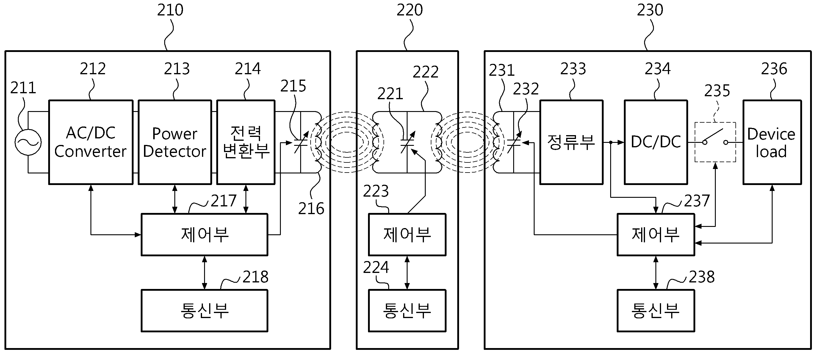
도 2는 일 실시 예에 따른 공진 주파수를 변경해서 커플링 효율을 높이는 무선전력 시스템의 구성을 나타낸다.2 illustrates a configuration of a wireless power system that improves the coupling efficiency by changing the resonant frequency according to an embodiment.
도 2를 참조하면, 무선전력 전송 시스템은 소스 장치(210), 중계 장치(220) 및 타겟 장치(230)를 포함한다. 2, the wireless power transmission system includes a
소스 장치(210)는 AC/DC 컨버터(211), Power Detector(213), 전력변환부(214), 소스 공진기(216), 제어부(217) 및 통신부(218)를 포함한다. 이때, 소스 공진기(216)는 가변 케페시터(215)를 포함한다.The
중계 장치(220)는 가변 캐페시터(221)를 구비하는 중계 공진기(222), 제어부(223) 및 통신부(224)를 포함한다.The
타겟 장치(230)는 가변 캐페시터(232)를 구비하는 타겟 공진기(321), 정류부(233), DC/DC 컨버터(234), 스위치부(235), 디바이스 로드(Device load)(236) 및 제어부(237) 및 통신부(238)를 포함한다. The
도 2에서 AC/DC 컨버터(211), Power Detector(213), 전력변환부(214), 정류부(233), DC/DC 컨버터(234), 스위치부(235) 및 디바이스 로드(Device load)(236)는 상술한 도 1과 동일하게 동작함으로 상세한 설명을 생략한다.In FIG. 2, an AC /
소스 장치(210)의 통신부(218), 중계 장치(220)의 통신부(224) 및 타겟 장치(230)의 통신부(238)는 통신 채널을 이용하는 아웃-밴드 통신을 수행할 수 도 있다. 통신부(218, 224, 238)들은 Zigbee, Bluetooth 등의 통신 모듈을 포함할 수 있다 통신부(218, 224, 238)들은 아웃-밴드 통신을 통해 소스 장치(210)와 중계 장치(220) 간, 소스 장치(210)와 타겟 장치(230), 중계 장치(220)와 타겟 장치(230) 간의 데이터를 송수신 할 수 있다.The
소스 장치(210)의 제어부(217)는 전송 효율을 계산하고, 전송 효율이 기설정된 기준 효율 보다 높지 않으면 소스 장치(210), 중계 장치(220) 및 타겟 장치(230) 각각의 공진 주파수를 조정하고, 각각의 조정된 공진 주파수들을 통신부(218)을 이용해서 중계 장치(220)와 타겟 장치(230)로 송신한다.The
제어부(217)는 소스 장치(210)의 공진 주파수가 조정된 경우, 소스 공진기(216)에 포함된 가변 캐페시터(215)를 조정해서 소스 공진기(216)의 공진 주파수를 조정된 공진 주파수로 조정한다. The
제어부(217)는 전송 효율이 기설정된 기준 효율 보다 높을 때까지 소스 장치(210), 중계 장치(220) 및 타겟 장치(230) 각각의 공진 주파수를 조정하고 전송효율을 계산한다.The
제어부(217)는 통신부(218)를 통해 타겟 장치(230)로부터 타겟 장치(230)에서 수신한 전력량을 나타내는 전력량 정보를 수신하고, 전력량 정보와 송신한 전력량을 이용해서 전송 효율을 계산한다.The
제어부(217)는 중계 장치(220)와 타겟 장치(230)로 각각의 조정된 공진 주파수들을 송신할 때, 공진 주파수 조정 메시지에 조정된 공진 주파수 정보를 포함시켜서 중계 장치(220)와 타겟 장치(230)로 송신한다. The
제어부(217)는 공진 주파수의 조정을 조정 리스트에 포함된 기설정된 조정 정보에 따라 조정한다. 조정 리스트에 포함된 기설정된 조정 정보는 기준 공진 주파수를 기준으로 소스 장치(210), 중계 장치(220) 및 타겟 장치(230) 각각에 대한 공진 주파수의 변화량을 나타내는 정보이다. 따라서, 소스 장치(210), 중계 장치(220) 및 타겟 장치(230) 각각에 대한 조정된 공진 주파수들은 서로 동일할 수도 있고, 일부만 동일할 수도 있고, 전부 다를 수도 있다. The
한편, 소스 장치(210)의 제어부(217)는 조정 리스트에 포함된 모든 조건들 각각에 따라 공진 주파수를 조정해서 무선전력 전송을 수행해서 조정 리스트에 포함된 모든 조건들에 따른 전송 효율을 계산해서 전송 효율이 가장 좋은 조건으로 소스 장치(210), 중계 장치(220) 및 타겟 장치(230) 각각의 공진 주파수들을 조정하도록 할 수도 있다.Meanwhile, the
중계 장치(220)의 제어부(223)는 기준 공진 주파수로 무선 전력을 중계하다가 소스 장치(210)로부터 조정된 공진 주파수를 수신하면, 조정된 공진 주파수로 무선 전력을 중계하도록 제어한다.The
제어부(223)는 중계 장치(220)의 공진 주파수가 조정된 경우, 중계 공진기(222)에 포함된 가변 캐페시터(221)를 조정해서 중계 공진기(222)의 공진 주파수를 조정된 공진 주파수로 조정한다. The
제어부(223)는 조정된 공진 주파수의 수신을 통신부(224)를 통해 조정된 공진 주파수 정보를 포함하는 공진 주파수 조정 메시지를 수신함으로써 확인할 수 있다.The
타겟 장치(230)의 제어부(237)는 기준 공진 주파수로 무선 전력을 수신하고 수신한 전력량을 계산해서 소스 장치(210)로 송신한다.The
제어부(237)는 조정된 공진 주파수를 수신하면, 조정된 공진 주파수로 무선 전력을 수신하도록 제어하고, 공진 주파수가 조정될 때마다 수신하는 전력량을 계산해서 소스 장치(210)로 송신한다.Upon receiving the adjusted resonance frequency, the
제어부(237)는 타겟 장치(230)의 공진 주파수가 조정된 경우, 타게 공진기(231)에 포함된 가변 캐페시터(232)를 조정해서 타게 공진기(231)의 공진 주파수를 조정된 공진 주파수로 조정한다. The
제어부(237)는 조정된 공진 주파수의 수신을 통신부(238)를 통해 조정된 공진 주파수 정보를 포함하는 공진 주파수 조정 메시지를 수신함으로써 확인할 수 있다.
The
도 3은 일 실시 예에 따른 무선전력 시스템의 소스 장치에서 공진 주파수를 조정하면서 무선 전력을 전송하는 흐름들 나타낸다.3 illustrates flows for transmitting wireless power while adjusting the resonant frequency in a source apparatus of a wireless power system according to an embodiment.
도 3을 참조하면, 소스 장치(210)는 310단계에서 기설정된 기준 공진 주파수로 무선 전력을 전송한다.Referring to FIG. 3, in
그리고, 소스 장치(210)는 312단계에서 타겟 장치(230)로부터 수신한 전력량 정보를 수신한다.Then, the
그리고, 소스 장치(210)는 314단계에서 수신한 전력량 정보를 이용해서 무선전력 전송의 전송 효율을 계산한다.Then, the
그리고, 소스 장치(210)는 316단계에서 전송 효율과 기설정된 기준 효율을 비교해서 전송 효율이 기준 효율 보다 큰지 여부를 확인한다.In
316단계의 확인결과 계산한 전송 효율이 기준 효율보다 높지 않으면, 소스 장치(210)는 318단계에서 소스 장치(210), 중계 장치(220) 및 타겟 장치(230) 각각의 공진 주파수를 조정한다. 조정 리스트에 포함된 기설정된 조정 정보에 따라 조정한다. 조정 리스트에 포함된 기설정된 조정 정보는 기준 공진 주파수를 기준으로 소스 장치(210), 중계 장치(220) 및 타겟 장치(230) 각각에 대한 공진 주파수의 변화량을 나타내는 정보이다. The
그리고, 소스 장치(210)는 320단계에서 조정된 공진 주파수를 중계 장치와 타겟 장치로 송신Then, the
그리고, 소스 장치(210)는 322단계에서 조정된 공진 주파수로 무선 전력 송신하고 312단계로 돌아간다.Then, the
312단계에서 322단계는 316단계의 확인결과 계산한 전송 효율이 기준 효율보다 높을 때까지 반복한다.
도 4는 일 실시 예에 따른 무선전력 시스템의 중계 장치에서 공진 주파수를 조정하면서 무선 전력을 중계하는 흐름들 나타낸다.4 illustrates flows for relaying wireless power while adjusting the resonant frequency in a repeater of a wireless power system according to one embodiment.
도 4를 참조하면, 중계 장치(220)는 410단계에서 중계 장치(220)의 공진기를 기설정된 기준 공진 주파수로 설정한다.Referring to FIG. 4, in
그리고, 중계 장치(220)는 412단계에서 기준 공진 주파수로 소스 장치(210)와 타겟 장치(230) 간의 무선 전력을 중계한다. 중계 장치가 다수개 인 경우 소스 장치와 다른 중계 장치, 다른 중계 장치와 또 다른 중계 장치 또는 다른 중계 장치와 타겟 장치 간의 무선 전력을 중계 할 수도 있다.In
그리고, 중계 장치(220)는 414단계에서 소스 장치(210)로부터 공진 주파수 조정 메시지를 수신하는지 확인한다.Then, in
414단계의 확인결과 소스 장치(210)로부터 공진 주파수 조정 메시지를 수신하면, 중계 장치(220)는 416단계에서 공진 주파수 조정 메시지에 포함된 공진 주파수 정보를 확인해서 공진 주파수 정보에 따라 중계 장치(220)의 공진 주파수를 조정한다.Upon receipt of the resonance frequency adjustment message from the
그리고, 중계 장치(220)는 410단계에서 조정된 공진 주파수로 무선 전력을 중계한다.
Then, the
도 5는 일 실시 예에 따른 무선전력 시스템의 타겟 장치에서 공진 주파수를 조정하면서 무선 전력을 수신하는 흐름들 나타낸다.5 illustrates flows for receiving wireless power while adjusting the resonant frequency in a target device of a wireless power system according to one embodiment.
도 5를 참조하면, 타겟 장치(230)는 510단계에서 타겟 장치(230)의 공진기를 기설정된 기준 공진 주파수로 설정한다.Referring to FIG. 5, the
그리고, 타겟 장치(230)는 512단계에서 무선 전력을 수신한다.Then, the
그리고, 타겟 장치(230)는 514단계에서 수신한 전력량을 계산해서 전력량 정보를 소스 장치(210)로 송신한다.Then, the
그리고, 타겟 장치(230)는 516단계에서 소스 장치(210)로부터 공진 주파수 조정 메시지를 수신하는지 확인한다.Then, in
516단계의 확인결과 소스 장치(210)로부터 공진 주파수 조정 메시지를 수신하면, 타겟 장치(230)는 518단계에서 공진 주파수 조정 메시지에 포함된 공진 주파수 정보를 확인해서 공진 주파수 정보에 따라 타겟 장치(230)의 공진 주파수를 조정한다.Upon receipt of the resonance frequency adjustment message from the
그리고, 타겟 장치(230)는 512단계로 돌아가 무선 전력을 수신한다.
The
도 6은 일 실시예에 따른 공진기 및 피더에서 자기장의 분포를 나타낸다.6 shows the distribution of the magnetic field in the resonator and feeder according to one embodiment.
별도의 피더를 통해 공진기가 전력을 공급받는 경우에는 피더에서 자기장이 발생하고, 공진기에서도 자기장이 발생한다. When the resonator is supplied with power through a separate feeder, a magnetic field is generated in the feeder and a magnetic field is generated in the resonator.
도 6의 (a)를 참조하면, 피더(610)에서 입력 전류가 흐름에 따라 자기장(630)이 발생한다. 피더(610) 내부에서 자기장의 방향(631)과 외부에서 자기장의 방향(633)은 서로 반대 위상을 가진다. 피더(610)에서 발생하는 자기장(630)에 의해 공진기(620)에서 유도 전류가 발생한다. 이때 유도 전류의 방향은 입력 전류의 방향과 반대이다.Referring to FIG. 6A, a
유도 전류에 의해 공진기(620)에서 자기장(640)이 발생한다. 자기장의 방향은 공진기(620)의 내부에서는 동일한 방향을 가진다. 따라서, 공진기(620)에 의해 피더(610)의 내부에서 발생하는 자기장의 방향(641)과 피더(610)의 외부에서 발생하는 자기장의 방향(643)은 동일한 위상을 가진다. A
결과적으로 피더(610)에 의해서 발생하는 자기장과 공진기(620)에서 발생하는 자기장을 합성하면, 피더(610)의 내부에서는 자기장의 세기가 약화되고, 피더(610)의 외부에서는 자기장의 세기가 강화된다. 따라서, 도 14와 같은 구조의 피더(610)를 통해 공진기(620)에 전력을 공급하는 경우에, 공진기(620) 중심에서 자기장의 세기가 약하고, 외곽에서 자기장의 세기가 강하다. 공진기(620) 상에서 자기장의 분포가 균일(uniform)하지 않은 경우, 입력 임피던스가 수시로 변화하므로 임피던스 매칭을 수행하는 것이 어렵다. 또한, 자기장의 세기가 강한 부분에서는 무선 전력 전송이 잘되고, 자기장의 세기가 약한 부분에서는 무선 전력 전송이 잘 되지 않으므로, 평균적으로 전력 전송 효율이 감소한다.As a result, by combining the magnetic field generated by the
도 6에서 (b)는 공진기(650)와 피더(660)가 공통의 접지를 가진 무선 전력 전송 장치의 구조를 나타낸다. 공진기(650)는 캐패시터(651)를 포함할 수 있다. 피더(660)는 포트(661)를 통하여, RF 신호를 입력 받을 수 있다. 피더(660)에는 RF 신호가 입력되어, 입력 전류가 생성될 수 있다. 피더(660)에 흐르는 입력 전류는 자기장을 생성하고, 상기 자기장으로부터 공진기(650)에 유도 전류가 유도된다. 또한, 공진기(650)를 흐르는 유도 전류로부터 자기장이 발생한다. 이때, 피더(660)에 흐르는 입력 전류의 방향과 공진기(650)에 흐르는 유도 전류의 방향은 서로 반대 위상을 가진다. 따라서, 공진기(650)와 피더(660) 사이의 영역에서, 입력 전류에 의해 발생하는 자기장의 방향(671)과 유도 전류에 의해 발생하는 자기장의 방향(673)은 동일한 위상을 가지므로, 자기장의 세기가 강화된다. 반면에, 피더(660)의 내부에서는, 입력 전류에 의해 발생하는 자기장의 방향(681)과 유도 전류에 의해 발생하는 자기장의 방향(683)은 반대 위상을 가지므로, 자기장의 세기가 약화된다. 결과적으로 공진기(650)의 중심에서는 자기장의 세기가 약해지고, 공진기(650)의 외곽에서는 자기장의 세기가 강화될 수 있다. 6 (b) shows the structure of a wireless power transmission apparatus in which the
피더(660)는 피더(660) 내부의 면적을 조절하여, 입력 임피던스를 결정할 수 있다. 여기서 입력 임피던스는 피더(660)에서 공진기(650)를 바라볼 때, 보이는 임피던스를 의미한다. 피더(660) 내부의 면적이 커지면 입력 임피던스는 증가하고, 내부의 면적이 작아지면 입력 임피던스는 감소한다. 그런데, 입력 임피던스가 감소하는 경우에도, 공진기(650) 내부의 자기장 분포는 일정하지 않으므로, 타겟 디바이스의 위치에 따라 입력 임피던스 값이 일정하지 않다. 따라서, 전력 증폭기의 출력 임피던스와 상기 입력 임피던스의 매칭을 위해 별도의 매칭 네트워크가 필요하다. 입력 임피던스가 증가하는 경우에는 큰 입력 임피던스를 작은 출력 임피던스에 매칭시키기 위해 별도의 매칭 네트워크가 필요할 수 있다.The
도 7은 일 실시예에 따른 공진기 및 피더의 구성을 나타낸 도면이다. 7 is a view showing a configuration of a resonator and a feeder according to an embodiment.
도 7의 (a)를 참조하면, 공진기(710)는 캐패시터(711)를 포함할 수 있다. 피딩부(720)는 캐패시터(711)의 양단에 전기적으로 연결될 수 있다.Referring to FIG. 7A, the
(b)는 (a)의 구조를 좀 더 구체적으로 표시한 도면이다. 이때, 공진기(710)는 제1 전송선로, 제1 도체(741), 제2 도체(742), 적어도 하나의 제1 캐패시터(750)를 포함할 수 있다. (b) is a diagram more specifically showing the structure of (a). At this time, the
제1 캐패시터(750)는 제1 전송 선로에서 제1 신호 도체 부분(731)과 제2 신호 도체 부분(732) 사이에 위치에 직렬로 삽입되며, 그에 따라 전계(electric field)는 제1 캐패시터(750)에 갇히게 된다. 일반적으로, 전송 선로는 상부에 적어도 하나의 도체, 하부에 적어도 하나의 도체를 포함하며, 상부에 있는 도체를 통해서는 전류가 흐르며, 하부에 있는 도체는 전기적으로 그라운드 된다(grounded). 본 명세서에서는 제1 전송 선로의 상부에 있는 도체를 제1 신호 도체 부분(731)과 제2 신호 도체 부분(732)로 나누어 부르고, 제1 전송 선로의 하부에 있는 도체를 제1 그라운드 도체 부분(733)으로 부르기로 한다.A
(b)에 도시된 바와 같이, 공진기는 2 차원 구조의 형태를 갖는다. 제1 전송 선로는 상부에 제1 신호 도체 부분(731) 및 제2 신호 도체 부분(732)을 포함하고, 하부에 제1 그라운드 도체 부분(733)을 포함한다. 제1 신호 도체 부분(731) 및 제2 신호 도체 부분(732)과 제1 그라운드 도체 부분(733)은 서로 마주보게 배치된다. 전류는 제1 신호 도체 부분(731) 및 제2 신호 도체 부분(732)을 통하여 흐른다.(b), the resonator has a form of a two-dimensional structure. The first transmission line includes a first
또한, (b)에 도시된 바와 같이 제1 신호 도체 부분(731)의 한쪽 단은 제1 도체(741)와 접지(short)되고, 다른 쪽 단은 제1 캐패시터(750)와 연결된다. 그리고, 제2 신호 도체 부분(732)의 한쪽 단은 제2 도체(742)와 접지되며, 다른 쪽 단은 제1 캐패시터(750)와 연결된다. 결국, 제1 신호 도체 부분(731), 제2 신호 도체 부분(732) 및 제1 그라운드 도체 부분(733), 도체들(741, 742)은 서로 연결됨으로써, 공진기는 전기적으로 닫혀 있는 루프 구조를 갖는다. 여기서, '루프 구조'는 원형 구조, 사각형과 같은 다각형의 구조 등을 모두 포함하며, '루프 구조를 갖는다고 함은' 전기적으로 닫혀 있다는 것을 의미한다.One end of the first
제1 캐패시터(750)는 전송 선로의 중단부에 삽입된다. 보다 구체적으로, 제1캐패시터(750)는 제1 신호 도체 부분(731) 및 제2 신호 도체 부분(732) 사이에 삽입된다. 이 때, 제1 캐패시터(750)는 집중 소자(lumped element) 및 분산 소자(distributed element) 등의 형태를 가질 수 있다. 특히, 분산 소자의 형태를 갖는 분산된 캐패시터는 지그재그 형태의 도체 라인들과 그 도체 라인들 사이에 존재하는 높은 유전율을 갖는 유전체를 포함할 수 있다.The
제1 캐패시터(750)가 전송 선로에 삽입됨에 따라 소스 공진기는 메타물질(metamaterial)의 특성을 가질 수 있다. 여기서, 메타물질이란 자연에서 발견될 수 없는 특별한 전기적 성질을 갖는 물질로서, 인공적으로 설계된 구조를 갖는다. 자연계에 존재하는 모든 물질들의 전자기 특성은 고유의 유전율 또는 투자율을 가지며, 대부분의 물질들은 양의 유전율 및 양의 투자율을 갖는다. As the
대부분의 물질들에서 전계, 자계 및 포인팅 벡터에는 오른손 법칙이 적용되므로, 이러한 물질들을 RHM(Right Handed Material)이라고 한다. 그러나, 메타물질은 자연계에 존재하지 않는 유전율 또는 투자율을 가진 물질로서, 유전율 또는 투자율의 부호에 따라 ENG(epsilon negative) 물질, MNG(mu negative) 물질, DNG(double negative) 물질, NRI(negative refractive index) 물질, LH(left-handed) 물질 등으로 분류된다.In most materials, the right-hand rule applies to electric fields, magnetic fields and pointing vectors, so these materials are called RHM (Right Handed Material). However, the meta-material is a material having a permittivity or permeability that does not exist in the natural world, and may be an epsilon negative material, an MNG (mu negative material), a DNG (double negative) material, index material, left-handed material, and the like.
이 때, 집중 소자로서 삽입된 제1 캐패시터(750)의 캐패시턴스가 적절히 정해지는 경우, 소스 공진기는 메타물질의 특성을 가질 수 있다. 특히, 제1 캐패시터(750)의 캐패시턴스를 적절히 조절함으로써, 소스 공진기는 음의 투자율을 가질 수 있으므로, 소스 공진기는 MNG 공진기로 불려질 수 있다. 제1 캐패시터(750)의 캐패시턴스를 정하는 전제(criterion)들은 다양할 수 있다. 소스 공진기가 메타물질(metamaterial)의 특성을 가질 수 있도록 하는 전제(criterion), 소스 공진기가 대상 주파수에서 음의 투자율을 갖도록 하는 전제 또는 소스 공진기가 대상 주파수에서 영번째 공진(Zeroth-Order Resonance) 특성을 갖도록 하는 전제 등이 있을 수 있고, 상술한 전제들 중 적어도 하나의 전제 아래에서 제1 캐패시터(750)의 캐패시턴스가 정해질 수 있다.At this time, when the capacitance of the
MNG 공진기는 전파 상수(propagation constant)가 0일 때의 주파수를 공진 주파수로 갖는 영번째 공진(Zeroth-Order Resonance) 특성을 가질 수 있다. MNG 공진기는 영번째 공진 특성을 가질 수 있으므로, 공진 주파수는 MNG 공진기의 물리적인 사이즈에 대해 독립적일 수 있다. 즉, 아래에서 다시 설명하겠지만, MNG 공진기에서 공진 주파수를 변경하기 위해서는 제1 캐패시터(750)를 적절히 설계하는 것으로 충분하므로, MNG 공진기의 물리적인 사이즈를 변경하지 않을 수 있다.The MNG resonator may have a zeroth-order resonance characteristic with a resonant frequency at a frequency of zero propagation constant. Since the MNG resonator may have a zero resonance characteristic, the resonance frequency may be independent of the physical size of the MNG resonator. That is, as will be described later, it is sufficient to appropriately design the
또한, 근접장(near field)에서 전계는 전송 선로에 삽입된 제1 캐패시터(750)에 집중되므로, 제1 캐패시터(750)로 인하여 근접 필드에서는 자기장(magnetic field)이 도미넌트(dominant)해진다. 그리고, MNG 공진기는 집중 소자의 제1 캐패시터(750)를 이용하여 높은 큐-팩터(Q-Factor)를 가질 수 있으므로, 전력 전송의 효율을 향상시킬 수 있다. 참고로, 큐-팩터는 무선 전력 전송에 있어서 저항 손실(ohmic loss)의 정도 또는 저항(resistance)에 대한 리액턴스의 비를 나타내는데, 큐-팩터가 클수록 무선 전력 전송의 효율이 큰 것으로 이해될 수 있다.Also, since the electric field in the near field is concentrated in the
또한, (b)에 도시되지 아니하였으나, MNG 공진기를 관통하는 마그네틱 코어가 더 포함될 수 있다. 이러한 마그네틱 코어는 전력 전송 거리를 증가시키는 기능을 수행할 수 있다.Further, although not shown in (b), a magnetic core passing through the MNG resonator may be further included. Such a magnetic core can perform a function of increasing a power transmission distance.
(b)를 참조하면, 피딩부(720)는 제2 전송선로, 제3 도체(771), 제4 도체(772), 제5 도체(781) 및 제6 도체(782)를 포함할 수 있다.(b), the feeding
제2 전송 선로는 상부에 제3 신호 도체 부분(761) 및 제4 신호 도체 부분(762)을 포함하고, 하부에 제2 그라운드 도체 부분(763)을 포함한다. 제3 신호 도체 부분(761) 및 제4 신호 도체 부분(762)과 제2 그라운드 도체 부분(763)은 서로 마주보게 배치된다. 전류는 제3 신호 도체 부분(761) 및 제4 신호 도체 부분(762)을 통하여 흐른다.The second transmission line includes a third
또한, (b)에 도시된 바와 같이 제3 신호 도체 부분(761)의 한쪽 단은 제3 도체(771)와 접지(short)되고, 다른 쪽 단은 제5 도체(781)와 연결된다. 그리고, 제4 신호 도체 부분(762)의 한쪽 단은 제4 도체(772)와 접지되며, 다른 쪽 단은 제6 도체 (782)와 연결된다. 제5 도체(781)는 제1 신호 도체 부분(731)과 연결되고, 제6 도체 (782)는 제2 신호 도체 부분(732)과 연결된다. 제5 도체(781)와 제6 도체(782)는 제1 캐패시터(750)의 양단에 병렬로 연결된다. 이때, 제5 도체(781) 및 제6 도체(782)는 RF신호를 입력받는 입력 포트로 사용될 수 있다.One end of the third
결국, 제3 신호 도체 부분(761), 제4 신호 도체 부분(762) 및 제2 그라운드 도체 부분(763), 제3 도체(771), 제4 도체(772), 제5 도체(781), 제6 도체(782) 및 공진기(710)는 서로 연결됨으로써, 공진기(710) 및 피딩부(720)는 전기적으로 닫혀 있는 루프 구조를 갖는다. 여기서, '루프 구조'는 원형 구조, 사각형과 같은 다각형의 구조 등을 모두 포함한다. 제5 도체(781) 또는 제6 도체(782)를 통하여 RF 신호가 입력되면, 입력 전류는 피딩부(720) 및 공진기(710)에 흐르게 되고, 입력 전류에 의해 발생하는 자기장에 의하여, 공진기(710)에 유도 전류가 유도 된다. 피딩부(720)에서 흐르는 입력 전류의 방향과 공진기(710)에서 흐르는 유도 전류의 방향이 동일하게 형성됨으로써, 공진기(710)의 중앙에서는 자기장의 세기가 강화되고, 공진기(710)의 외곽에서는 자기장의 세기가 약화된다. As a result, the third
공진기(710)와 피딩부(720) 사이 영역의 면적에 의해 입력 임피던스가 결정될 수 있으므로, 전력 증폭기의 출력 임피던스와 상기 입력 임피던스의 매칭을 수행하기 위해 별도의 매칭 네트워크는 필요하지 않다. 매칭 네트워크가 사용되는 경우에도, 피딩부(720)의 크기를 조절함으로써, 입력 임피던스를 결정할 수 있기 때문에, 매칭 네트워크의 구조는 단순해질 수 있다. 단순한 매칭 네트워크 구조는 매칭 네트워크의 매칭 손실을 최소화한다. Since the input impedance can be determined by the area of the region between the
제2 전송 선로, 제3 도체(771), 제4 도체(772), 제5 도체(781), 제6 도체(782) 는 공진기(710)와 동일한 구조를 형성할 수 있다. 즉, 공진기(710)가 루프 구조인 경우에는 피딩부(720)도 루프 구조일 수 있다. 또한, 공진기(710)가 원형 구조인 경우에는 피딩부(720)도 원형 구조일 수 있다.
The third conductor 771, the
도 8는 일 실시예에 따른 피딩부의 피딩에 따른 공진기의 내부에서 자기장의 분포를 나타낸 도면이다.8 is a view showing a distribution of a magnetic field in a resonator according to feeding of a feeding part according to an embodiment.
무선 전력 전송에서 피딩은, 소스 공진기에 전력을 공급하는 것을 의미한다. 또한, 무선 전력 전송에서 피딩은, 정류부에 AC 전력을 공급하는 것을 의미할 수 있다. 도 8의 (a)는 피딩부에서 흐르는 입력 전류의 방향 및 소스 공진기에서 유도되는 유도 전류의 방향을 나타낸다. 또한, (a)는 피딩부의 입력 전류에 의해 발생하는 자기장의 방향 및 소스 공진기의 유도 전류에 의해 발생하는 자기장의 방향을 나타낸다. (a)는 도 7의 공진기(710) 및 피딩부(720)를 좀 더 간략하게 표현한 도면이다. (b)는 피딩부와 공진기의 등가회로를 나타낸다.Feeding in a wireless power transmission implies supplying power to the source resonator. Also, in wireless power transmission, feeding can mean supplying AC power to the rectifying section. 8 (a) shows the direction of the input current flowing in the feeding portion and the direction of the induced current induced in the source resonator. (A) shows the direction of the magnetic field generated by the input current of the feeding portion and the direction of the magnetic field generated by the induced current of the source resonator. (a) is a more simplified representation of the
(a)를 참조하면, 피딩부의 제5 도체 또는 제6 도체는 입력 포트(810)로 사용될 수 있다. 입력 포트(810)는 RF 신호를 입력 받는다. RF 신호는 전력 증폭기로부터 출력될 수 있다. 전력 증폭기는 타겟 장치의 필요에 따라 RF 신호의 진폭을 증감시킬 수 있다. 입력 포트(810)에서 입력된 RF 신호는 피딩부에 흐르는 입력 전류의 형태로 표시될 수 있다. 피딩부를 흐르는 입력 전류는 피딩부의 전송선로를 따라 시계방향으로 흐른다. 그런데, 피딩부의 제5 도체는 공진기와 전기적으로 연결된다. 좀 더 구체적으로, 제5 도체는 공진기의 제1 신호 도체 부분과 연결된다. 따라서 입력 전류는 피딩부 뿐만 아니라 공진기에도 흐르게 된다. 공진기에서 입력 전류는 반시계 방향으로 흐른다. 공진기에 흐르는 입력 전류에 의하여 자기장이 발생하고, 상기 자기장에 의해 공진기에 유도 전류가 생성된다. 유도 전류는 공진기에서 시계방향으로 흐른다. 이때 유도 전류는 공진기의 캐패시터에 에너지를 전달할 수 있다. 또한, 유도 전류에 의해 자기장이 발생한다. (a)에서 피딩부 및 공진기에 흐르는 입력 전류는 실선으로 표시되고, 공진기에 흐르는 유도 전류는 점선으로 표시되었다. (a), the fifth conductor or the sixth conductor of the feeding portion may be used as the
전류에 의해 발생하는 자기장의 방향은 오른나사의 법칙을 통해 알 수 있다. 피딩부 내부에서, 피딩부에 흐르는 입력 전류에 의해 발생한 자기장의 방향(821)과 공진기에 흐르는 유도 전류에 의해 발생한 자기장의 방향(823)은 서로 동일하다. 따라서, 피딩부 내부에서 자기장의 세기가 강화된다. The direction of the magnetic field generated by the current can be determined by the right-hand rule. The
또한, 피딩부와 공진기 사이의 영역에서, 피딩부에 흐르는 입력 전류에 의해 발생한 자기장의 방향(833)과 소스 공진기에 흐르는 유도 전류에 의해 발생한 자기장의 방향(831)은 서로 반대 위상이다. 따라서, 피딩부와 공진기 사이의 영역에서, 자기장의 세기는 약화된다.In the region between the feeding portion and the resonator, the
루프 형태의 공진기에서는 일반적으로 공진기의 중심에서는 자기장의 세기가 약하고, 공진기의 외곽부분에서는 자기장의 세기가 강하다. 그런데 (a)를 참조하면, 피딩부가 공진기의 캐패시터 양단에 전기적으로 연결됨으로써 공진기의 유도 전류의 방향과 피딩부의 입력 전류의 방향이 동일해 진다. 공진기의 유도 전류의 방향과 피딩부의 입력 전류의 방향이 동일하기 때문에, 피딩부의 내부에서는 자기장의 세기가 강화되고, 피딩부의 외부에서는 자기장의 세기가 약화된다. 결과적으로 루프 형태의 공진기의 중심에서는 피딩부로 인하여 자기장의 세기가 강화되고, 공진기의 외곽부분에서는 자기장의 세기가 약화될 수 있다. 그러므로 공진기 내부에서는 전체적으로 자기장의 세기가 균일해질 수 있다. In a loop type resonator, the intensity of the magnetic field is generally weak at the center of the resonator and strong at the outer portion of the resonator. However, referring to (a), since the feeding portion is electrically connected to both ends of the capacitor of the resonator, the direction of the induced current of the resonator becomes the same as the direction of the input current of the feeding portion. Since the direction of the induced current of the resonator is the same as the direction of the input current of the feeding portion, the strength of the magnetic field is strengthened inside the feeding portion and the strength of the magnetic field outside the feeding portion is weakened. As a result, at the center of the loop-shaped resonator, the strength of the magnetic field is enhanced due to the feeding portion, and the strength of the magnetic field at the outer portion of the resonator is weakened. Therefore, the intensity of the magnetic field can be uniform throughout the resonator.
한편, 소스 공진기에서 타겟 공진기로 전달되는 전력 전송의 효율은 소스 공진기에서 발생하는 자기장의 세기에 비례하므로, 소스 공진기의 중심에서 자기장의 세기가 강화됨에 따라 전력 전송 효율도 증가할 수 있다. On the other hand, since the efficiency of the power transmission from the source resonator to the target resonator is proportional to the intensity of the magnetic field generated in the source resonator, the power transmission efficiency can be increased as the strength of the magnetic field is strengthened at the center of the source resonator.
(b)를 참조하면, 피딩부(840) 및 공진기(850)는 등가회로로 표현될 수 있다. 피딩부(840)에서 공진기 측을 바라볼 때 보이는 입력 임피던스 Zin은 다음의 수식과 같이 계산될 수 있다. (b), the feeding

여기서, M은 피딩부(840)와 공진기(850) 사이의 상호 인덕턴스를 의미하고, ω 는 피딩부(840)와 공진기(850) 간의 공진 주파수를 의미하고, Z는 공진기(850)에서 타겟 장치 측을 바라볼 때 보이는 임피던스를 의미한다. Zin은 상호 인덕턴스 M에 비례한다. 따라서, 피딩부(840)와 공진기(850) 사이에 상호 인덕턴스를 조절함으로써 Zin을 제어할 수 있다. 상호 인덕턴스 M은 피딩부(840)와 공진기(850) 사이 영역의 면적에 따라 조절될 수 있다. 피딩부(840)의 크기에 따라 피딩부(840)와 공진기(850) 사이 영역의 면적이 조절될 수 있다. Zin은 피딩부(840)의 크기에 따라 결정될 수 있으므로, 전력 증폭기의 출력 임피던스와 임피던스 매칭을 수행하기 위해 별도의 매칭 네트워크가 필요하지 않다. Here, M denotes a mutual inductance between the
무선 전력 수신 장치에 포함된 타겟 공진기 및 피딩부도 위와 같은 자기장의 분포를 가질 수 있다. 타겟 공진기는 소스 공진기로부터 마그네틱 커플링을 통하여 무선 전력을 수신한다. 이때 수신되는 무선 전력을 통하여 타겟 공진기에서는 유도 전류가 생성될 수 있다. 타겟 공진기에서 유도 전류에 의해 발생한 자기장은 피딩부에 다시 유도 전류를 생성할 수 있다. 이때, (a)의 구조와 같이 타겟 공진기와 피딩부가 연결되면, 타겟 공진기에서 흐르는 전류의 방향과 피딩부에서 흐르는 전류의 방향은 동일해진다. 따라서, 피딩부의 내부에서는 자기장의 세기가 강화되고, 피딩부와 타겟 공진기 사이의 영역에서는 자기장의 세기가 약화될 수 있다.
The target resonator and the feeding portion included in the wireless power receiving apparatus may have a distribution of the magnetic field as described above. The target resonator receives radio power from the source resonator through magnetic coupling. At this time, an induced current can be generated in the target resonator through the received radio power. The magnetic field generated by the induced current in the target resonator can generate the induced current again in the feeding part. At this time, when the target resonator and the feeding portion are connected as in the structure of (a), the direction of the current flowing in the target resonator becomes the same as the direction of the current flowing in the feeding portion. Therefore, the strength of the magnetic field can be strengthened inside the feeding portion, and the strength of the magnetic field in the region between the feeding portion and the target resonator can be weakened.
본 발명의 실시 예에 따른 방법들은 다양한 컴퓨터 수단을 통하여 수행될 수 있는 프로그램 명령 형태로 구현되어 컴퓨터 판독 가능 매체에 기록될 수 있다. 상기 컴퓨터 판독 가능 매체는 프로그램 명령, 데이터 파일, 데이터 구조 등을 단독으로 또는 조합하여 포함할 수 있다. 상기 매체에 기록되는 프로그램 명령은 본 발명을 위하여 특별히 설계되고 구성된 것들이거나 컴퓨터 소프트웨어 당업자에게 공지되어 사용 가능한 것일 수도 있다. The methods according to embodiments of the present invention may be implemented in the form of program instructions that can be executed through various computer means and recorded in a computer-readable medium. The computer-readable medium may include program instructions, data files, data structures, and the like, alone or in combination. The program instructions recorded on the medium may be those specially designed and constructed for the present invention or may be available to those skilled in the art of computer software.
이상과 같이 본 발명은 비록 한정된 실시예와 도면에 의해 설명되었으나, 본 발명은 상기의 실시예에 한정되는 것은 아니며, 본 발명이 속하는 분야에서 통상의 지식을 가진 자라면 이러한 기재로부터 다양한 수정 및 변형이 가능하다.While the invention has been shown and described with reference to certain preferred embodiments thereof, it will be understood by those of ordinary skill in the art that various changes in form and details may be made therein without departing from the spirit and scope of the invention as defined by the appended claims. This is possible.
그러므로, 본 발명의 범위는 설명된 실시예에 국한되어 정해져서는 아니 되며, 후술하는 특허청구범위뿐 아니라 이 특허청구범위와 균등한 것들에 의해 정해져야 한다.Therefore, the scope of the present invention should not be limited to the described embodiments, but should be determined by the equivalents of the claims, as well as the claims.
Claims (15)
중계 장치와 타겟 장치로부터 정보를 수신하고, 상기 중계 장치의 조정된 공진 주파수의 정보를 상기 중계 장치로 송신하고, 상기 타겟 장치의 조정된 공진 주파수의 정보를 상기 타겟 장치로 송신하는 통신부; 및
전력 전송 효율을 계산하고, 상기 전력 전송 효율이 기설정된 기준 효율 보다 높지 않으면, 상기 전력 전송 효율이 기설정된 기준 효율 보다 높아질 때까지 상기 소스 장치, 상기 중계 장치 및 상기 타겟 장치의 공진 주파수의 조정을 반복하도록 제어하는 제어부를 포함하고,
상기 소스 장치의 조정된 공진 주파수, 상기 중계 장치의 조정된 공진 주파수 및 상기 타겟 장치의 조정된 공진 주파수 중에서 적어도 하나는 나머지 장치와 다른 공진 주파수를 가지는
공진 주파수를 조정해서 커플링 효율을 높이는 무전전력 전송 시스템의 소스 장치.
A source resonator comprising a variable capacitor, the source resonator transmitting wireless power based on the adjusted resonant frequency of the source device;
A communication unit that receives information from the relay apparatus and the target apparatus, transmits information of the adjusted resonance frequency of the relay apparatus to the relay apparatus, and transmits information of the adjusted resonance frequency of the target apparatus to the target apparatus; And
Calculating the power transmission efficiency and adjusting the resonance frequency of the source apparatus, the relay apparatus, and the target apparatus until the power transmission efficiency becomes higher than a predetermined reference efficiency, if the power transmission efficiency is not higher than the predetermined reference efficiency And a control unit for controlling the control unit so as to repeat,
At least one of an adjusted resonant frequency of the source device, an adjusted resonant frequency of the relay device, and an adjusted resonant frequency of the target device,
A source device for an electroluminescent transmission system that adjusts the resonant frequency to increase coupling efficiency.
출력 전류 및 전압을 검출하고, 검출된 상기 전류 및 상기 전압에 대한 정보를 상기 제어부를 전달하는 전력 검출부를 더 포함하고,
상기 제어부는,
상기 전력 검출부로부터 수신하는 상기 전류 및 상기 전압에 대한 정보를 이용해서 송신한 전력량을 계산하고, 상기 타겟 장치에서 수신한 전력량 정보를 상기 타겟 장치로부터 수신해서 상기 수신한 전력량과 상기 송신한 전력량을 이용해서 상기 전송 효율을 계산하는
공진 주파수를 조정해서 커플링 효율을 높이는 무전전력 전송 시스템의 소스 장치.
The method according to claim 1,
Further comprising a power detector for detecting an output current and a voltage, and transmitting information about the detected current and the voltage to the controller,
Wherein,
Calculating a transmitted amount of power using information on the current and the voltage received from the power detecting unit, receiving the amount of power information received by the target apparatus from the target apparatus, and using the received amount of power and the amount of transmitted power To calculate the transmission efficiency
A source device for an electroluminescent transmission system that adjusts the resonant frequency to increase coupling efficiency.
상기 제어부는,
기설정된 조정 리스트에 포함된 상기 소스 장치, 상기 중계 장치 및 상기 타겟 장치 각각에 대한 기설정된 변경 정보를 상기 소스 장치, 상기 중계 장치 및 상기 타겟 장치 각각의 현재 공진 주파수에 적용해서 상기 소스 장치, 상기 중계 장치 및 상기 타겟 장치 각각에 대한 상기 조정된 공진 주파수 정보들을 확인하는
공진 주파수를 조정해서 커플링 효율을 높이는 무전전력 전송 시스템의 소스 장치.
The method according to claim 1,
Wherein,
The relay device and the target device included in the preset adjustment list to the current resonance frequency of each of the source device, the relay device, and the target device, The relay device and the target device,
A source device for an electroluminescent transmission system that adjusts the resonant frequency to increase coupling efficiency.
상기 제어부는,
상기 가변 캐패시터의 캐패시턴스 값을 조정해서 상기 공진 주파수를 조정하는
공진 주파수를 조정해서 커플링 효율을 높이는 무전전력 전송 시스템의 소스 장치.
The method according to claim 1,
Wherein,
And adjusting the capacitance value of the variable capacitor to adjust the resonance frequency
A source device for an electroluminescent transmission system that adjusts the resonant frequency to increase coupling efficiency.
전력 전송 효율을 계산하는 단계;
상기 전력 전송 효율이 기설정된 기준 효율 보다 높지 않으면, 상기 전력 전송 효율이 기설정된 기준 효율 보다 높아질 때까지 상기 소스 장치, 중계 장치 및 타겟 장치의 공진 주파수의 조정을 반복하는 단계를 포함하고,
상기 전송 효율을 계산하는 단계는,
상기 타겟 장치에서 수신한 전력량 정보를 상기 타겟 장치로부터 수신해서 상기 수신한 전력량과 송신한 전력량을 이용해서 계산하고,
상기 소스 장치의 조정된 공진 주파수, 상기 중계 장치의 조정된 공진 주파수 및 상기 타겟 장치의 조정된 공진 주파수 중에서 적어도 하나는 나머지 장치와 다른 공진 주파수를 가지는
무전전력 전송 시스템의 소스 장치에서 공진 주파수를 조정해서 커플링 효율을 높이는 방법.
Transmitting wireless power based on the adjusted resonant frequency of the source device;
Calculating power transmission efficiency;
Repeating adjusting the resonance frequency of the source apparatus, the relay apparatus, and the target apparatus until the power transmission efficiency becomes higher than a predetermined reference efficiency, if the power transmission efficiency is not higher than the predetermined reference efficiency,
Wherein the step of calculating the transmission efficiency comprises:
Receiving the power amount information received by the target apparatus from the target apparatus, calculating the power amount using the received power amount and the transmitted power amount,
At least one of an adjusted resonant frequency of the source device, an adjusted resonant frequency of the relay device, and an adjusted resonant frequency of the target device,
A method of increasing the coupling efficiency by adjusting the resonance frequency in a source device of an electrolone power transmission system.
상기 전송 효율을 계산하는 단계에서 상기 소스 장치의 상기 조정된 공진 주파수로 무선 전력을 전송하는 단계를 상기 전송 효율이 상기 기준 효율 보다 높을 때까지 반복하는
무전전력 전송 시스템의 소스 장치에서 공진 주파수를 조정해서 커플링 효율을 높이는 방법.
9. The method of claim 8,
Transmitting the wireless power at the adjusted resonant frequency of the source device in the calculating of the transmission efficiency until the transmission efficiency is higher than the reference efficiency
A method of increasing the coupling efficiency by adjusting the resonance frequency in a source device of an electrolone power transmission system.
상기 소스 장치, 상기 중계 장치 및 상기 타겟 장치 각각에 대한 조정된 공진 주파수 정보들을 확인하는 단계는,
실험에 의해 기설정된 조정 리스트에 포함된 상기 소스 장치, 상기 중계 장치 및 상기 타겟 장치 각각에 대한 기설정된 변경 정보를 상기 소스 장치, 상기 중계 장치 및 상기 타겟 장치 각각의 현재 공진 주파수에 적용해서 확인하는
무전전력 전송 시스템의 소스 장치에서 공진 주파수를 조정해서 커플링 효율을 높이는 방법.
9. The method of claim 8,
Wherein the step of verifying adjusted resonant frequency information for each of the source device, the relay device, and the target device comprises:
The relay device and the target device included in the adjustment list preset by the experiment by applying the preset change information to each of the source device, the relay device and the target device, respectively,
A method of increasing the coupling efficiency by adjusting the resonance frequency in a source device of an electrolone power transmission system.
상기 소스 장치는
상기 소스 장치의 조정된 공진 주파수에 기초하여 무선전력을 송신하는 소스 공진기;
상기 중계 장치와 상기 타겟 장치로부터 정보를 수신하고, 상기 중계 장치의 조정된 공진 주파수의 정보를 상기 중계 장치로 송신하고, 상기 타겟 장치의 조정된 공진 주파수의 정보를 상기 타겟 장치로 송신하는 통신부; 및
전력 전송 효율을 계산하고, 상기 전력 전송 효율이 기설정된 기준 효율 보다 높지 않으면, 상기 전력 전송 효율이 기설정된 기준 효율 보다 높아질 때까지 상기 소스 장치, 상기 중계 장치 및 상기 타겟 장치의 공진 주파수의 조정을 반복하도록 제어하는 제어부를 포함하고,
상기 중계 장치는,
상기 중계 장치의 조정된 공진 주파수에 기초하여 무선전력을 중계하고,
상기 타겟 장치는,
상기 타겟 장치의 조정된 공진 주파수에 기초하여 무선전력을 수신하고,
상기 소스 장치의 조정된 공진 주파수, 상기 중계 장치의 조정된 공진 주파수 및 상기 타겟 장치의 조정된 공진 주파수 중에서 적어도 하나는 나머지 장치와 다른 공진 주파수를 가지는
무전전력 전송 시스템.
A wireless power transmission system comprising a source apparatus, a relay apparatus and a target apparatus,
The source device
A source resonator for transmitting wireless power based on the adjusted resonant frequency of the source device;
A communication unit that receives information from the relay device and the target device, transmits information of the adjusted resonance frequency of the relay device to the relay device, and transmits information of the adjusted resonance frequency of the target device to the target device; And
Calculating the power transmission efficiency and adjusting the resonance frequency of the source apparatus, the relay apparatus, and the target apparatus until the power transmission efficiency becomes higher than a predetermined reference efficiency, if the power transmission efficiency is not higher than the predetermined reference efficiency And a control unit for controlling the control unit so as to repeat,
The relay apparatus includes:
Relay the wireless power based on the adjusted resonance frequency of the relay device,
The target device includes:
Receive radio power based on an adjusted resonant frequency of the target device,
At least one of an adjusted resonant frequency of the source device, an adjusted resonant frequency of the relay device, and an adjusted resonant frequency of the target device,
Radio transmission system.
상기 소스 장치는,
상기 타겟 장치에서 수신한 전력량 정보를 상기 타겟 장치로부터 수신해서 상기 수신한 전력량과 송신한 전력량을 이용해서 계산하는
무전전력 전송 시스템.
14. The method of claim 13,
Wherein the source device comprises:
Receives the power amount information received from the target device from the target device, and calculates the power amount information using the received power amount and the transmitted power amount
Radio transmission system.
상기 소스 장치는,
기설정된 조정 리스트에 포함된 상기 소스 장치, 상기 중계 장치 및 상기 타겟 장치 각각에 대한 기설정된 변경 정보를 상기 소스 장치, 상기 중계 장치 및 상기 타겟 장치 각각의 현재 공진 주파수에 적용해서 상기 소스 장치, 상기 중계 장치 및 상기 타겟 장치 각각에 대한 상기 조정된 공진 주파수 정보들을 확인하는
무전전력 전송 시스템.14. The method of claim 13,
Wherein the source device comprises:
The relay device and the target device included in the preset adjustment list to the current resonance frequency of each of the source device, the relay device, and the target device, The relay device and the target device,
Radio transmission system.
Priority Applications (2)
| Application Number | Priority Date | Filing Date | Title |
|---|---|---|---|
| KR1020120030164A KR101988009B1 (en) | 2012-03-23 | 2012-03-23 | Wireless power transmission system and method that controls resonance frequency and increases coupling efficiency |
| US13/742,992 US9997959B2 (en) | 2012-03-23 | 2013-01-16 | Wireless power transmission system and method for increasing coupling efficiency by adjusting resonant frequency |
Applications Claiming Priority (1)
| Application Number | Priority Date | Filing Date | Title |
|---|---|---|---|
| KR1020120030164A KR101988009B1 (en) | 2012-03-23 | 2012-03-23 | Wireless power transmission system and method that controls resonance frequency and increases coupling efficiency |
Publications (2)
| Publication Number | Publication Date |
|---|---|
| KR20130107955A KR20130107955A (en) | 2013-10-02 |
| KR101988009B1 true KR101988009B1 (en) | 2019-06-11 |
Family
ID=49211119
Family Applications (1)
| Application Number | Title | Priority Date | Filing Date |
|---|---|---|---|
| KR1020120030164A Expired - Fee Related KR101988009B1 (en) | 2012-03-23 | 2012-03-23 | Wireless power transmission system and method that controls resonance frequency and increases coupling efficiency |
Country Status (2)
| Country | Link |
|---|---|
| US (1) | US9997959B2 (en) |
| KR (1) | KR101988009B1 (en) |
Families Citing this family (36)
| Publication number | Priority date | Publication date | Assignee | Title |
|---|---|---|---|---|
| KR101832331B1 (en) * | 2011-06-29 | 2018-02-26 | 엘지전자 주식회사 | Wireless power transmission and communication between devices |
| JP6126225B2 (en) * | 2013-08-30 | 2017-05-10 | パイオニア株式会社 | Non-contact power receiving system, non-contact power transmission system, control method, computer program, and recording medium |
| TWI519031B (en) * | 2013-10-29 | 2016-01-21 | 國美科技有限公司 | Automatic sensing wireless charging system |
| US9775200B2 (en) | 2014-02-12 | 2017-09-26 | Philips Lighting Holding B.V. | Illumination system comprising an array of LEDs |
| CN103986245B (en) * | 2014-06-04 | 2016-08-03 | 中国矿业大学(北京) | Radio energy transmission system based on double-layer double-direction spiral winding and method |
| US10084343B2 (en) | 2014-06-13 | 2018-09-25 | Empire Technology Development Llc | Frequency changing encoded resonant power transfer |
| US9635222B2 (en) | 2014-08-03 | 2017-04-25 | PogoTec, Inc. | Wearable camera systems and apparatus for aligning an eyewear camera |
| TWI584018B (en) | 2014-08-03 | 2017-05-21 | 帕戈技術股份有限公司 | Wearable camera systems and apparatus and method for attaching camera systems or other electronic devices to wearable articles |
| US10320228B2 (en) | 2014-09-08 | 2019-06-11 | Empire Technology Development Llc | Power coupling device |
| US10069324B2 (en) | 2014-09-08 | 2018-09-04 | Empire Technology Development Llc | Systems and methods for coupling power to devices |
| KR102056404B1 (en) * | 2014-09-11 | 2019-12-16 | 주식회사 위츠 | Wireless power transmitting device and Controlling method thereof |
| TW201724837A (en) | 2014-12-23 | 2017-07-01 | 帕戈技術股份有限公司 | Wearable camera, system for providing wireless power, method for wirelessly providing power, and method for processing image |
| US10355530B2 (en) * | 2015-03-12 | 2019-07-16 | Panasonic Intellectual Property Management Co., Ltd. | Non-contact power supply apparatus, program, method for controlling non-contact power supply apparatus, and non-contact power transmission system |
| US10243389B2 (en) * | 2015-03-27 | 2019-03-26 | Goodrich Corporation | Systems and methods for near resonant wireless power and data transfer |
| US10481417B2 (en) | 2015-06-10 | 2019-11-19 | PogoTec, Inc. | Magnetic attachment mechanism for electronic wearable device |
| WO2016201261A1 (en) | 2015-06-10 | 2016-12-15 | PogoTec, Inc. | Eyewear with magnetic track for electronic wearable device |
| US10056785B2 (en) | 2015-09-02 | 2018-08-21 | Semiconductor Components Industries, Llc | Tunable/de-tunable wireless power resonator system and related methods |
| WO2017075405A1 (en) | 2015-10-29 | 2017-05-04 | PogoTec, Inc. | Hearing aid adapted for wireless power reception |
| US11558538B2 (en) | 2016-03-18 | 2023-01-17 | Opkix, Inc. | Portable camera system |
| SG11201900590PA (en) * | 2016-07-28 | 2019-02-27 | Razer Asia Pacific Pte Ltd | Receiver devices, transmitter devices, methods for controlling a receiver device, methods for controlling a transmitter device, and computer-readable media |
| WO2018089533A1 (en) | 2016-11-08 | 2018-05-17 | PogoTec, Inc. | A smart case for electronic wearable device |
| WO2018163169A1 (en) * | 2017-03-07 | 2018-09-13 | Powermat Technologies Ltd. | System for wireless power charging |
| KR102601200B1 (en) * | 2017-03-07 | 2023-11-09 | 파워매트 테크놀로지스 엘티디. | wireless power charging system |
| KR101996127B1 (en) * | 2017-05-26 | 2019-07-03 | 울산대학교 산학협력단 | Wireless power transmission system based on Coupled Electric Field |
| JP2020533939A (en) | 2017-09-15 | 2020-11-19 | ジーエヌ ヒアリング エー/エスGN Hearing A/S | Non-contact charging method for rechargeable hearing equipment |
| WO2020102237A1 (en) | 2018-11-13 | 2020-05-22 | Opkix, Inc. | Wearable mounts for portable camera |
| KR102718668B1 (en) | 2019-05-14 | 2024-10-18 | 삼성전자주식회사 | Device and method for transmit power wirelessly |
| JP7447457B2 (en) | 2019-12-12 | 2024-03-12 | 株式会社デンソー | Contactless power supply system |
| KR102813246B1 (en) * | 2020-08-31 | 2025-05-28 | 삼성디스플레이 주식회사 | Display device and the electronic device including the same |
| US20220158490A1 (en) * | 2020-11-17 | 2022-05-19 | Hsiang En Hsu | Long distance wireless mobile phone power charging device |
| CN112491164B (en) * | 2020-12-02 | 2022-08-19 | 同济大学 | High-order space-time symmetrical wireless energy transmission system and method |
| CN112615440B (en) * | 2020-12-25 | 2022-11-29 | 国网北京市电力公司 | Wireless power transmission device and wireless power transmission system |
| TWI794795B (en) * | 2021-04-26 | 2023-03-01 | 國立陽明交通大學 | Inductive resonant wireless charging system, resonant wireless charging transmitting device, wireless charging relay device and inductive wireless charging receiving device |
| KR20230090502A (en) * | 2021-12-15 | 2023-06-22 | 주식회사 반프 | A wireless power transmission system that searches for the optimal resonant frequency, and search method using of it |
| KR102789718B1 (en) | 2022-08-03 | 2025-04-03 | 주식회사 반프 | Wireless power transmission system for optimal power transmission and optimal resonance frequency control method of the system |
| KR102669364B1 (en) * | 2022-11-10 | 2024-05-27 | 경희대학교 산학협력단 | Simultaneous wireless information and power transfer system and operating method thereof |
Citations (3)
| Publication number | Priority date | Publication date | Assignee | Title |
|---|---|---|---|---|
| JP2011147280A (en) * | 2010-01-15 | 2011-07-28 | Sony Corp | Wireless power supply system |
| WO2012001959A1 (en) | 2010-07-02 | 2012-01-05 | パナソニック株式会社 | Contactless power transmission device |
| WO2012020475A1 (en) * | 2010-08-10 | 2012-02-16 | パイオニア株式会社 | Impedance matching device, and control method |
Family Cites Families (24)
| Publication number | Priority date | Publication date | Assignee | Title |
|---|---|---|---|---|
| GB2414120B (en) | 2004-05-11 | 2008-04-02 | Splashpower Ltd | Controlling inductive power transfer systems |
| US7825543B2 (en) * | 2005-07-12 | 2010-11-02 | Massachusetts Institute Of Technology | Wireless energy transfer |
| WO2010036279A1 (en) * | 2007-11-28 | 2010-04-01 | Qualcomm Incorporated | Wireless power range increase using parasitic antennas |
| JP4974171B2 (en) | 2007-12-07 | 2012-07-11 | ソニーモバイルコミュニケーションズ株式会社 | Non-contact wireless communication device, method for adjusting resonance frequency of non-contact wireless communication antenna, and portable terminal device |
| EP2269283B1 (en) * | 2008-04-15 | 2016-08-10 | Toyota Jidosha Kabushiki Kaisha | Wireless energy transfer device |
| JP4911148B2 (en) | 2008-09-02 | 2012-04-04 | ソニー株式会社 | Contactless power supply |
| US8907531B2 (en) * | 2008-09-27 | 2014-12-09 | Witricity Corporation | Wireless energy transfer with variable size resonators for medical applications |
| JP5515659B2 (en) | 2008-12-01 | 2014-06-11 | 株式会社豊田自動織機 | Non-contact power transmission device |
| JP5244578B2 (en) | 2008-12-24 | 2013-07-24 | 株式会社日立製作所 | Non-contact power transmission system |
| JP2010183812A (en) | 2009-02-09 | 2010-08-19 | Toyota Industries Corp | Resonance type non-contact charging system |
| JP5262785B2 (en) | 2009-02-09 | 2013-08-14 | 株式会社豊田自動織機 | Non-contact power transmission device |
| JP2010183813A (en) | 2009-02-09 | 2010-08-19 | Toyota Industries Corp | Resonant contactless charging system |
| JP5365276B2 (en) * | 2009-03-17 | 2013-12-11 | ソニー株式会社 | Power transmission system and power output device |
| JP5470963B2 (en) | 2009-03-27 | 2014-04-16 | 日産自動車株式会社 | Power supply device |
| US8994225B2 (en) | 2009-07-06 | 2015-03-31 | Samsung Electronics Co., Ltd. | Wireless power transmission system and resonator for the system |
| JP5499534B2 (en) | 2009-07-07 | 2014-05-21 | ソニー株式会社 | Non-contact power receiving apparatus, power receiving method in non-contact power receiving apparatus, and non-contact power feeding system |
| JP5434330B2 (en) | 2009-07-22 | 2014-03-05 | ソニー株式会社 | Power receiving device, power transmission system, charging device, and power transmission method |
| JP5387201B2 (en) | 2009-07-23 | 2014-01-15 | ソニー株式会社 | Non-contact power feeding system, non-contact relay device, non-contact power receiving device, and non-contact power feeding method |
| JP2011050140A (en) | 2009-08-26 | 2011-03-10 | Sony Corp | Non-contact electric power feeding apparatus, non-contact power electric receiver receiving apparatus, non-contact electric power feeding method, non-contact electric power receiving method and non-contact electric power feeding system |
| KR20110062841A (en) * | 2009-12-04 | 2011-06-10 | 한국전자통신연구원 | Wireless power transmitter |
| JP5526796B2 (en) * | 2010-01-15 | 2014-06-18 | ソニー株式会社 | Wireless power supply rack |
| AU2012289855A1 (en) * | 2011-08-04 | 2014-03-13 | Witricity Corporation | Tunable wireless power architectures |
| US8823217B2 (en) * | 2011-08-31 | 2014-09-02 | Alpha Microelectronics Corp. | One-to-many wireless energy transmission system |
| US20140084688A1 (en) * | 2012-09-21 | 2014-03-27 | Samsung Electronics Co. Ltd | Method and apparatus for wireless power transmission |
-
2012
- 2012-03-23 KR KR1020120030164A patent/KR101988009B1/en not_active Expired - Fee Related
-
2013
- 2013-01-16 US US13/742,992 patent/US9997959B2/en not_active Expired - Fee Related
Patent Citations (3)
| Publication number | Priority date | Publication date | Assignee | Title |
|---|---|---|---|---|
| JP2011147280A (en) * | 2010-01-15 | 2011-07-28 | Sony Corp | Wireless power supply system |
| WO2012001959A1 (en) | 2010-07-02 | 2012-01-05 | パナソニック株式会社 | Contactless power transmission device |
| WO2012020475A1 (en) * | 2010-08-10 | 2012-02-16 | パイオニア株式会社 | Impedance matching device, and control method |
Also Published As
| Publication number | Publication date |
|---|---|
| US9997959B2 (en) | 2018-06-12 |
| US20130249306A1 (en) | 2013-09-26 |
| KR20130107955A (en) | 2013-10-02 |
Similar Documents
| Publication | Publication Date | Title |
|---|---|---|
| KR101988009B1 (en) | Wireless power transmission system and method that controls resonance frequency and increases coupling efficiency | |
| KR101813264B1 (en) | Wireless power transmission system, method and apparatus for power control in power transmission system | |
| KR101809470B1 (en) | Wireless power transmission system, method and apparatus for resonance frequency tracking in wireless power transmission system | |
| KR101817194B1 (en) | Wireless power transmission system using solar cell module | |
| KR101880030B1 (en) | Sauce apparatus and method that control magnetic field using two sauce resonators in Wireless Resonant Power Transfer system | |
| KR101926009B1 (en) | Method and electronic device for transmitting and receiving wireless power | |
| KR101896979B1 (en) | Wireless power transmission and charging system, and control method of resonant frequency of wireless power transmission and charging system | |
| KR101947982B1 (en) | Apparatus and method for controlling resonator of wireless power transfer system | |
| KR101318742B1 (en) | Wireless power transmission system and design method of wireless power transmission system considering impedence matching condition | |
| KR101947980B1 (en) | Method and apparatus for wireless power transmission and wireless power reception apparatus | |
| KR101813131B1 (en) | Wireless power transmission system and method for controlling of resonance frequency and resonance impedance of wireless power transmission system | |
| KR101813125B1 (en) | Wireless power transmission system, method for power control of in wireless power transmission system using detecting parameter | |
| KR101925959B1 (en) | Wireless power transmission and charging system, and control method of impedance of wireless power transmission and charging system | |
| KR101808086B1 (en) | Sound system using wireless power transmission | |
| KR101829257B1 (en) | Wireless power transmission system based on cell division | |
| KR101859191B1 (en) | Method and apparatus for controlling wireless power transmission and reception, and wireless power transmission system | |
| KR101985820B1 (en) | Method and apparatus for transmitting and receiving wireless power | |
| KR102227504B1 (en) | Wireless power transfer method and device to trasmit power stably to plural wireless power receiving devices | |
| KR101882273B1 (en) | Method and apparatus for wireless power reception and method and apparatus for wireless power transmission | |
| KR102000525B1 (en) | In band data communication system using wireless power | |
| KR20140008020A (en) | Wireless power transmitter, wireless power relay device and wireless power receiver | |
| KR101897160B1 (en) | Apparatus and method that divide wireless power in Wireless Resonant Power Transmission System | |
| KR101962747B1 (en) | Apparatus and method for shielding leakage magnetic field of wireless power transfer system | |
| KR20140085727A (en) | Method and apparatus for resonating in wireless power transfer system | |
| KR20150010029A (en) | Method and aparatus of detecting coupling region |
Legal Events
| Date | Code | Title | Description |
|---|---|---|---|
| PA0109 | Patent application |
St.27 status event code: A-0-1-A10-A12-nap-PA0109 |
|
| R18-X000 | Changes to party contact information recorded |
St.27 status event code: A-3-3-R10-R18-oth-X000 |
|
| PG1501 | Laying open of application |
St.27 status event code: A-1-1-Q10-Q12-nap-PG1501 |
|
| A201 | Request for examination | ||
| PA0201 | Request for examination |
St.27 status event code: A-1-2-D10-D11-exm-PA0201 |
|
| D13-X000 | Search requested |
St.27 status event code: A-1-2-D10-D13-srh-X000 |
|
| D14-X000 | Search report completed |
St.27 status event code: A-1-2-D10-D14-srh-X000 |
|
| E902 | Notification of reason for refusal | ||
| PE0902 | Notice of grounds for rejection |
St.27 status event code: A-1-2-D10-D21-exm-PE0902 |
|
| AMND | Amendment | ||
| E13-X000 | Pre-grant limitation requested |
St.27 status event code: A-2-3-E10-E13-lim-X000 |
|
| P11-X000 | Amendment of application requested |
St.27 status event code: A-2-2-P10-P11-nap-X000 |
|
| P13-X000 | Application amended |
St.27 status event code: A-2-2-P10-P13-nap-X000 |
|
| E601 | Decision to refuse application | ||
| PE0601 | Decision on rejection of patent |
St.27 status event code: N-2-6-B10-B15-exm-PE0601 |
|
| AMND | Amendment | ||
| E13-X000 | Pre-grant limitation requested |
St.27 status event code: A-2-3-E10-E13-lim-X000 |
|
| P11-X000 | Amendment of application requested |
St.27 status event code: A-2-2-P10-P11-nap-X000 |
|
| P13-X000 | Application amended |
St.27 status event code: A-2-2-P10-P13-nap-X000 |
|
| PX0901 | Re-examination |
St.27 status event code: A-2-3-E10-E12-rex-PX0901 |
|
| E902 | Notification of reason for refusal | ||
| PE0902 | Notice of grounds for rejection |
St.27 status event code: A-1-2-D10-D21-exm-PE0902 |
|
| AMND | Amendment | ||
| P11-X000 | Amendment of application requested |
St.27 status event code: A-2-2-P10-P11-nap-X000 |
|
| P13-X000 | Application amended |
St.27 status event code: A-2-2-P10-P13-nap-X000 |
|
| P22-X000 | Classification modified |
St.27 status event code: A-2-2-P10-P22-nap-X000 |
|
| P22-X000 | Classification modified |
St.27 status event code: A-2-2-P10-P22-nap-X000 |
|
| PX0701 | Decision of registration after re-examination |
St.27 status event code: A-3-4-F10-F13-rex-PX0701 |
|
| X701 | Decision to grant (after re-examination) | ||
| GRNT | Written decision to grant | ||
| PR0701 | Registration of establishment |
St.27 status event code: A-2-4-F10-F11-exm-PR0701 |
|
| PR1002 | Payment of registration fee |
St.27 status event code: A-2-2-U10-U11-oth-PR1002 Fee payment year number: 1 |
|
| PG1601 | Publication of registration |
St.27 status event code: A-4-4-Q10-Q13-nap-PG1601 |
|
| P22-X000 | Classification modified |
St.27 status event code: A-4-4-P10-P22-nap-X000 |
|
| PC1903 | Unpaid annual fee |
St.27 status event code: A-4-4-U10-U13-oth-PC1903 Not in force date: 20220605 Payment event data comment text: Termination Category : DEFAULT_OF_REGISTRATION_FEE |
|
| PC1903 | Unpaid annual fee |
St.27 status event code: N-4-6-H10-H13-oth-PC1903 Ip right cessation event data comment text: Termination Category : DEFAULT_OF_REGISTRATION_FEE Not in force date: 20220605 |
|
| P22-X000 | Classification modified |
St.27 status event code: A-4-4-P10-P22-nap-X000 |