KR101976276B1 - Control apparatus of electronic limited slip differential and control method thereof - Google Patents
Control apparatus of electronic limited slip differential and control method thereof Download PDFInfo
- Publication number
- KR101976276B1 KR101976276B1 KR1020170138964A KR20170138964A KR101976276B1 KR 101976276 B1 KR101976276 B1 KR 101976276B1 KR 1020170138964 A KR1020170138964 A KR 1020170138964A KR 20170138964 A KR20170138964 A KR 20170138964A KR 101976276 B1 KR101976276 B1 KR 101976276B1
- Authority
- KR
- South Korea
- Prior art keywords
- wheel
- vehicle
- yaw rate
- front wheel
- angle
- Prior art date
- Legal status (The legal status is an assumption and is not a legal conclusion. Google has not performed a legal analysis and makes no representation as to the accuracy of the status listed.)
- Active
Links
- 238000000034 method Methods 0.000 title claims abstract description 19
- 238000013016 damping Methods 0.000 claims abstract description 25
- 230000001133 acceleration Effects 0.000 claims description 12
- 230000005484 gravity Effects 0.000 claims description 9
- 230000008859 change Effects 0.000 description 2
- 238000010586 diagram Methods 0.000 description 2
- 230000007935 neutral effect Effects 0.000 description 2
- 230000006866 deterioration Effects 0.000 description 1
- 230000009699 differential effect Effects 0.000 description 1
- 230000008569 process Effects 0.000 description 1
- 230000009467 reduction Effects 0.000 description 1
- 239000004576 sand Substances 0.000 description 1
- 238000009987 spinning Methods 0.000 description 1
Images


Classifications
-
- B—PERFORMING OPERATIONS; TRANSPORTING
- B60—VEHICLES IN GENERAL
- B60W—CONJOINT CONTROL OF VEHICLE SUB-UNITS OF DIFFERENT TYPE OR DIFFERENT FUNCTION; CONTROL SYSTEMS SPECIALLY ADAPTED FOR HYBRID VEHICLES; ROAD VEHICLE DRIVE CONTROL SYSTEMS FOR PURPOSES NOT RELATED TO THE CONTROL OF A PARTICULAR SUB-UNIT
- B60W10/00—Conjoint control of vehicle sub-units of different type or different function
- B60W10/12—Conjoint control of vehicle sub-units of different type or different function including control of differentials
- B60W10/14—Central differentials for dividing torque between front and rear axles
-
- B—PERFORMING OPERATIONS; TRANSPORTING
- B60—VEHICLES IN GENERAL
- B60K—ARRANGEMENT OR MOUNTING OF PROPULSION UNITS OR OF TRANSMISSIONS IN VEHICLES; ARRANGEMENT OR MOUNTING OF PLURAL DIVERSE PRIME-MOVERS IN VEHICLES; AUXILIARY DRIVES FOR VEHICLES; INSTRUMENTATION OR DASHBOARDS FOR VEHICLES; ARRANGEMENTS IN CONNECTION WITH COOLING, AIR INTAKE, GAS EXHAUST OR FUEL SUPPLY OF PROPULSION UNITS IN VEHICLES
- B60K17/00—Arrangement or mounting of transmissions in vehicles
- B60K17/04—Arrangement or mounting of transmissions in vehicles characterised by arrangement, location or kind of gearing
- B60K17/16—Arrangement or mounting of transmissions in vehicles characterised by arrangement, location or kind of gearing of differential gearing
- B60K17/20—Arrangement or mounting of transmissions in vehicles characterised by arrangement, location or kind of gearing of differential gearing in which the differential movement is limited
-
- B—PERFORMING OPERATIONS; TRANSPORTING
- B60—VEHICLES IN GENERAL
- B60W—CONJOINT CONTROL OF VEHICLE SUB-UNITS OF DIFFERENT TYPE OR DIFFERENT FUNCTION; CONTROL SYSTEMS SPECIALLY ADAPTED FOR HYBRID VEHICLES; ROAD VEHICLE DRIVE CONTROL SYSTEMS FOR PURPOSES NOT RELATED TO THE CONTROL OF A PARTICULAR SUB-UNIT
- B60W30/00—Purposes of road vehicle drive control systems not related to the control of a particular sub-unit, e.g. of systems using conjoint control of vehicle sub-units
- B60W30/02—Control of vehicle driving stability
- B60W30/045—Improving turning performance
-
- B—PERFORMING OPERATIONS; TRANSPORTING
- B60—VEHICLES IN GENERAL
- B60W—CONJOINT CONTROL OF VEHICLE SUB-UNITS OF DIFFERENT TYPE OR DIFFERENT FUNCTION; CONTROL SYSTEMS SPECIALLY ADAPTED FOR HYBRID VEHICLES; ROAD VEHICLE DRIVE CONTROL SYSTEMS FOR PURPOSES NOT RELATED TO THE CONTROL OF A PARTICULAR SUB-UNIT
- B60W40/00—Estimation or calculation of non-directly measurable driving parameters for road vehicle drive control systems not related to the control of a particular sub unit, e.g. by using mathematical models
- B60W40/10—Estimation or calculation of non-directly measurable driving parameters for road vehicle drive control systems not related to the control of a particular sub unit, e.g. by using mathematical models related to vehicle motion
- B60W40/105—Speed
-
- B—PERFORMING OPERATIONS; TRANSPORTING
- B60—VEHICLES IN GENERAL
- B60W—CONJOINT CONTROL OF VEHICLE SUB-UNITS OF DIFFERENT TYPE OR DIFFERENT FUNCTION; CONTROL SYSTEMS SPECIALLY ADAPTED FOR HYBRID VEHICLES; ROAD VEHICLE DRIVE CONTROL SYSTEMS FOR PURPOSES NOT RELATED TO THE CONTROL OF A PARTICULAR SUB-UNIT
- B60W40/00—Estimation or calculation of non-directly measurable driving parameters for road vehicle drive control systems not related to the control of a particular sub unit, e.g. by using mathematical models
- B60W40/10—Estimation or calculation of non-directly measurable driving parameters for road vehicle drive control systems not related to the control of a particular sub unit, e.g. by using mathematical models related to vehicle motion
- B60W40/114—Yaw movement
-
- B—PERFORMING OPERATIONS; TRANSPORTING
- B60—VEHICLES IN GENERAL
- B60W—CONJOINT CONTROL OF VEHICLE SUB-UNITS OF DIFFERENT TYPE OR DIFFERENT FUNCTION; CONTROL SYSTEMS SPECIALLY ADAPTED FOR HYBRID VEHICLES; ROAD VEHICLE DRIVE CONTROL SYSTEMS FOR PURPOSES NOT RELATED TO THE CONTROL OF A PARTICULAR SUB-UNIT
- B60W2510/00—Input parameters relating to a particular sub-units
- B60W2510/12—Differentials
-
- B—PERFORMING OPERATIONS; TRANSPORTING
- B60—VEHICLES IN GENERAL
- B60W—CONJOINT CONTROL OF VEHICLE SUB-UNITS OF DIFFERENT TYPE OR DIFFERENT FUNCTION; CONTROL SYSTEMS SPECIALLY ADAPTED FOR HYBRID VEHICLES; ROAD VEHICLE DRIVE CONTROL SYSTEMS FOR PURPOSES NOT RELATED TO THE CONTROL OF A PARTICULAR SUB-UNIT
- B60W2520/00—Input parameters relating to overall vehicle dynamics
- B60W2520/10—Longitudinal speed
-
- B—PERFORMING OPERATIONS; TRANSPORTING
- B60—VEHICLES IN GENERAL
- B60W—CONJOINT CONTROL OF VEHICLE SUB-UNITS OF DIFFERENT TYPE OR DIFFERENT FUNCTION; CONTROL SYSTEMS SPECIALLY ADAPTED FOR HYBRID VEHICLES; ROAD VEHICLE DRIVE CONTROL SYSTEMS FOR PURPOSES NOT RELATED TO THE CONTROL OF A PARTICULAR SUB-UNIT
- B60W2520/00—Input parameters relating to overall vehicle dynamics
- B60W2520/14—Yaw
-
- B—PERFORMING OPERATIONS; TRANSPORTING
- B60—VEHICLES IN GENERAL
- B60W—CONJOINT CONTROL OF VEHICLE SUB-UNITS OF DIFFERENT TYPE OR DIFFERENT FUNCTION; CONTROL SYSTEMS SPECIALLY ADAPTED FOR HYBRID VEHICLES; ROAD VEHICLE DRIVE CONTROL SYSTEMS FOR PURPOSES NOT RELATED TO THE CONTROL OF A PARTICULAR SUB-UNIT
- B60W2520/00—Input parameters relating to overall vehicle dynamics
- B60W2520/28—Wheel speed
-
- B—PERFORMING OPERATIONS; TRANSPORTING
- B60—VEHICLES IN GENERAL
- B60W—CONJOINT CONTROL OF VEHICLE SUB-UNITS OF DIFFERENT TYPE OR DIFFERENT FUNCTION; CONTROL SYSTEMS SPECIALLY ADAPTED FOR HYBRID VEHICLES; ROAD VEHICLE DRIVE CONTROL SYSTEMS FOR PURPOSES NOT RELATED TO THE CONTROL OF A PARTICULAR SUB-UNIT
- B60W2540/00—Input parameters relating to occupants
- B60W2540/18—Steering angle
Landscapes
- Engineering & Computer Science (AREA)
- Transportation (AREA)
- Mechanical Engineering (AREA)
- Automation & Control Theory (AREA)
- Physics & Mathematics (AREA)
- Mathematical Physics (AREA)
- Chemical & Material Sciences (AREA)
- Combustion & Propulsion (AREA)
- Control Of Driving Devices And Active Controlling Of Vehicle (AREA)
Abstract
본 발명은 전자식 LSD의 제어장치 및 그 제어방법이 개시된다. 본 발명의 전자식 LSD의 제어장치는, 차량 내 감지장치와 차량제어장치로부터 차량 거동정보를 수집하는 차량거동 수집부; 차륜의 토크를 각각 제어하는 차동제한 구동부; 및 차량거동 수집부로부터 수집된 운전자의 조향상태와 차량의 거동상태를 기반으로 과소조향계수를 추정하여 요속도 오차를 산출하고, 요속도 오차로부터 요 댐핑 목표토크를 산출하여 차동제한 구동부를 제어하는 제어부;를 포함하는 것을 특징으로 한다. An electronic LSD control apparatus and a control method thereof are disclosed. A control device for an electronic LSD according to the present invention comprises: a vehicle behavior collecting part for collecting vehicle behavior information from an in-vehicle sensing device and a vehicle control device; A differential limiting driver for controlling the torque of the wheel; And a yaw damping target torque from the yaw rate error to calculate a yaw damping target torque by estimating a subordinate steering coefficient based on the driver's steering state and the vehicle behavior state collected from the vehicle behavior collector and controlling the differential limiting driver And a control unit.
Description
본 발명은 전자식 LSD의 제어장치 및 그 제어방법에 관한 것으로서, 보다 상세하게는 전륜 차량의 고속 주행 중 급격한 조향시 요 댐핑을 제어하여 안정성을 향상시키기 위한 전자식 LSD의 제어장치 및 그 제어방법에 관한 것이다. [0001] The present invention relates to a control apparatus for an electronic LSD and a control method thereof, and more particularly to an electronic LSD control apparatus and control method thereof for controlling stability of yaw damping during steep steering during a high- will be.
일반적으로, 차동제한장치(LSD ; limited slip differential)란 차동장치의 차동작용이 제한되도록 하는 장치를 말한다. In general, limited slip differential (LSD) refers to a device that limits the differential action of a differential.
보다 구체적으로, 차동장치는 자동차가 회전할 때와 같이 엔진의 동력을 좌우 구동바퀴에 차이를 두어 전달하도록 한다. More specifically, the differential device allows the power of the engine to be transmitted with a difference between the left and right drive wheels, such as when the vehicle is rotating.
만약 구동바퀴의 한 쪽이 모래에 빠지게 되면, 차동장치는 대부분의 동력을 바진 쪽 바퀴에 전달해 빠진 바퀴는 더 빠른 회전을 하면서 계속 헛돌게 되며, 반대로 바지지 않은 바퀴에는 동력이 거의 전달되지 않아 동력을 많이 받는 바퀴만 점점 더 빠져들어 결국 헤어나지 못하는 현상이 발생한다. If one side of the drive wheel falls into the sand, the differential transfers most of the power to the idle wheels, the missing wheels continue to idle while spinning faster, and vice versa, The more you lose, the more you lose.
전자식 차동제한장치는 양쪽 바퀴의 회전수가 일정 수준 이상으로 차이가 나게 되면 회전수가 적은 쪽으로 구동력을 전달하여 양쪽 바퀴의 회전수 차이를 일정 수준 이하로 제한함으로써 위와 같은 차동장치의 단점을 해결하는 장치이다. The electronic differential limiting device solves the disadvantages of the above-mentioned differential device by limiting the difference in the number of revolutions of both wheels to a certain level by transmitting the driving force to the one having a small number of revolutions when the number of revolutions of both wheels is more than a certain level .
일반적인 전자식 차동제한장치는 이종 마찰로에서의 원활한 발진과 선회 시의 견인력 저하를 방지하기 위해 구동륜의 좌우 휠 슬립량 기반의 제어기법, 차량 요레이트 제어기법, 견인력 추정 기반 제어기법 등으로 개발되고 있다. The conventional electronic differential limiting device has been developed to prevent the smooth running of the two-way friction wheels and the reduction of the traction force at the time of turning, such as the control method based on the left and right wheel slip amount of the driving wheel, the vehicle yaw rate control technique, .
한편, 전륜 전자식 차동제한장치는 전륜에서 발생하는 좌우 동력 차이를 줄여 보다 안정적인 코너링이 가능하도록 한다. On the other hand, the front-wheel electronic differential limiting device reduces the difference in power between the front wheels and the left wheels, thereby enabling more stable cornering.
하지만 전륜에 장착되기 때문에 높은 토크로 제어 할 경우에는 운전자가 의도한 조향 방향으로 선회하는 것을 방해하게 되며, 토크를 줄여주면 회전은 가능하지만 전륜의 좌우 비대칭 탈출이 어려워진다는 단점이 있다.However, since it is mounted on the front wheel, when it is controlled with a high torque, the driver is prevented from turning in the intended steering direction, and if the torque is reduced, it is possible to rotate but it is disadvantageous that asymmetric escape of the front wheel becomes difficult.
본 발명의 배경기술은 대한민국 등록특허공보 제1546629호(2015.08.24. 공고, 전륜 차량의 전자식 LSD 토크 제어 방법)에 개시되어 있다. BACKGROUND ART [0002] The background art of the present invention is disclosed in Korean Patent Registration No. 1546629 (published on Aug. 25, 2014, an electronic LSD torque control method for a front wheel drive vehicle).
따라서 종래의 전자식 차동제한장치에서는 조향각과 좌우 휠의 속도차(또는 슬립량)을 이용하여 좌우 휠의 회전 불균형 상황을 탈출하여 선회 성능 저하를 방지하고 있으나, 휠 슬립이 발생한 이후에 동작하게 됨으로서 제어 반응이 느려져 안정성이 저하되는 문제점이 있었다. Therefore, in the conventional electronic differential limiting device, the rotation unbalance situation of the left and right wheels is escaped by using the steering angle and the speed difference (or slip amount) of the left and right wheels to prevent the deterioration of the turning performance. However, There is a problem that the reaction is slowed and the stability is lowered.
본 발명은 상기와 같은 문제점들을 개선하기 위하여 안출된 것으로, 일 측면에 따른 본 발명의 목적은 전륜 차량의 고속 주행 중 급격한 조향시 요 댐핑을 제어하여 구동축의 강성을 높이고 차량의 거동변화를 둔감하게 하여 안정성을 향상시키는 전자식 LSD의 제어장치 및 그 제어방법을 제공하는 것이다. SUMMARY OF THE INVENTION The present invention has been made in order to solve the above-mentioned problems, and it is an object of the present invention to provide a steering control device for a vehicle, Thereby improving the stability of the electronic LSD and a control method thereof.
본 발명의 일 측면에 따른 전자식 LSD의 제어장치는, 차량 내 감지장치와 차량제어장치로부터 차량 거동정보를 수집하는 차량거동 수집부; 차륜의 토크를 각각 제어하는 차동제한 구동부; 및 차량거동 수집부로부터 수집된 운전자의 조향상태와 차량의 거동상태를 기반으로 과소조향계수를 추정하여 요속도 오차를 산출하고, 요속도 오차로부터 요 댐핑 목표토크를 산출하여 차동제한 구동부를 제어하는 제어부;를 포함하는 것을 특징으로 한다. An apparatus for controlling an electronic LSD according to an aspect of the present invention includes: a vehicle behavior collector for collecting vehicle behavior information from an in-vehicle sensing apparatus and a vehicle control apparatus; A differential limiting driver for controlling the torque of the wheel; And a yaw damping target torque from the yaw rate error to calculate a yaw damping target torque by estimating a subordinate steering coefficient based on the driver's steering state and the vehicle behavior state collected from the vehicle behavior collector and controlling the differential limiting driver And a control unit.
본 발명에서 제어부는, 차량거동 수집부로부터 수집된 조향 핸들각을 통해 전륜 좌측 바퀴의 회전각과 전륜 우측 바퀴의 회전각을 산출하고, 전륜 바퀴의 회전각을 산출하는 휠각 연산부; 차량거동 수집부로부터 수집된 차륜별 속도, 차량 제동상태, 종가속도, 횡가속도 및 현재 요속도와, 휠각 연산부에서 산출된 전륜 좌측 바퀴의 회전각 및 전륜 우측 바퀴의 회전각을 기반으로 종방향 차속을 추정하는 차속 추정부; 차속 추정부에서 추정된 종방향 차속, 휠각 연산부에서 산출한 전륜 바퀴의 회전각, 전륜과 후륜의 슬립각 편차, 차량의 휠베이스 길이 및 횡가속도를 기반으로 과소조향계수를 추정하는 과소조향계수 추정부; 차속 추정부에서 추정된 종방향 차속, 과소조향계수 및 차량의 휠베이스 길이를 기반으로 산출된 정상상태 선회의 요속도 게인과 전륜 바퀴의 회전각을 기반으로 목표 요속도를 추정하는 목표 요속도 추정부; 목표 요속도 추정부에서 추정된 목표 요속도와 현재 요속도와의 편차 및 목표 요속도와 현재 요속도의 상태에 따라 부호를 설정하여 요속도 오차를 산출하는 요속도 오차 연산부; 및 요속도 오차 연산부에서 산출된 요속도 오차에 제어 옵셋 보정치를 반영하여 비례제어를 통해 요댐핑 목표토크를 산출하는 요댐핑 제어기;를 포함하는 것을 특징으로 한다. The control unit may include a wheel angle calculation unit for calculating a rotation angle of the front wheel left wheel and a front wheel right wheel through the steering wheel angle collected from the vehicle behavior collecting unit and calculating a rotational angle of the front wheel; Based on the wheel speed, the vehicle braking state, the closing speed, the lateral acceleration and the current yaw rate collected from the vehicle behavior collecting unit, the rotation angle of the front wheel left wheel and the rotation angle of the front wheel right wheel, A vehicle speed estimating unit for estimating a vehicle speed; A subordinate steering coefficient estimating subordinate steering coefficient based on the longitudinal vehicle speed estimated by the vehicle speed estimating unit, the rotational angle of the front wheel calculated by the wheel angle calculating unit, the slip angle deviation of the front wheel and the rear wheel, government; A target yaw rate estimating means for estimating a target yaw rate based on the yaw rate gain of the steady state turning calculated based on the estimated longitudinal vehicle speed, the understeering coefficient and the wheel base length of the vehicle, and the rotational angle of the front wheel, government; A yaw rate error calculator for calculating a yaw rate error by setting a sign according to a deviation between a target yaw rate estimated by a target yaw rate estimator and a current yaw rate and a state of a target yaw rate and a current yaw rate; And a yaw damping controller for calculating a yaw damping target torque through proportional control by reflecting a control offset correction value to the yaw rate error calculated by the yaw rate error calculation unit.
본 발명에서 휠각 연산부는, 조향 핸들각으로부터 전륜 좌측 바퀴의 회전각과 전륜 우측 바퀴의 회전각을 연산하고, 차량의 자전거 모델을 통해 전륜 바퀴의 회전각을 산출하는 것을 특징으로 한다. In the present invention, the wheel angle calculation unit calculates the rotational angle of the left wheel of the front wheel and the rotational angle of the front wheel right wheel from the steering wheel angle, and calculates the rotational angle of the front wheel through the bicycle model of the vehicle.
본 발명에서 차속 추정부는, 차량이 제동되지 않은 상태에서는 각 차륜의 차량 무게중심에 대한 상대속도 중 가장 작은 값으로 종방향 차속을 추정하고, 제동되고 있는 상태에서는 각 차륜의 차량 무게중심에 대한 상대속도 중 가장 큰 값으로 종방향 차속을 추정하는 것을 특징으로 한다. In the present invention, the vehicle speed estimating section estimates the longitudinal vehicle speed at a minimum value among the relative speeds of the respective wheels with respect to the center of gravity of the vehicle in a state in which the vehicle is not braked, And the longitudinal vehicle speed is estimated to be the largest value among the speeds.
본 발명의 다른 측면에 따른 전자식 LSD의 제어방법은, 제어부가 차량거동 정보를 수집하는 단계; 제어부가 수집된 조향 핸들각을 통해 전륜 좌측 바퀴의 외전각과 전륜 우측 바퀴의 회전각을 연산하고, 전륜 바퀴의 회전각을 산출하는 단계; 제어부가 수집된 차륜별 속도, 차량 제동상태, 종가속도, 횡가속도, 현재 요속도, 전륜 좌측 바퀴의 회전각 및 전륜 우측 바퀴의 회전각을 기반으로 종방향 차속을 추정하는 단계; 제어부가 추정된 종방향 차속, 전륜 바퀴의 회전각, 전륜과 후륜의 슬립각 편차, 차량의 휠베이스 길이 및 횡가속도를 기반으로 과소조향계수를 추정하는 단계; 제어부가 추정된 종방향 차속, 과소조향계수 및 차량의 휠베이스 길이를 기반으로 산출된 정상상태 선회의 요속도 게인과 전륜 바퀴의 회전각을 기반으로 목표 요속도를 추정 단계; 제어부가 추정된 목표 요속도와 현재 요속도와의 편차 및 목표 요속도와 현재 요속도의 상태에 따라 부호를 설정하여 요속도 오차를 산출 단계; 제어부가 산출된 요속도 오차에 제어 옵셋 보정치를 반영하여 비례제어를 통해 요댐핑 목표토크를 산출 단계; 및 제어부가 산출된 요댐핑 목표토크를 통해 차동제한 구동부를 제어하는 단계;를 포함하는 것을 특징으로 한다. According to another aspect of the present invention, there is provided a method of controlling an electronic LSD, the method including: a controller collecting vehicle behavior information; Calculating a rotation angle of the right wheel of the front wheel and an outward angle of the front wheel left wheel through the collected steering wheel angle, and calculating a rotation angle of the front wheel; Estimating a longitudinal vehicle speed based on the collected speed of each wheel, the vehicle braking state, the closing speed, the lateral acceleration, the current yaw rate, the rotational angle of the front wheel left wheel and the front wheel right wheel; Estimating an understeering coefficient based on the estimated longitudinal vehicle speed, the rotational angle of the front wheel, the slip angle deviation of the front wheel and the rear wheel, the wheel base length and the lateral acceleration of the vehicle; Estimating the target yaw rate based on the yaw rate gain of the steady state turning calculated based on the estimated longitudinal vehicle speed, the understeering coefficient, and the wheel base length of the vehicle and the rotational angle of the front wheel; Calculating a yaw rate error by setting a sign according to the deviation between the estimated yaw rate and the current yaw rate and the state of the target yaw rate and the current yaw rate; Calculating a yaw damping target torque through proportional control by reflecting a control offset correction value to a yaw rate error calculated by the control unit; And controlling the differential limiting driver based on the calculated yaw damping target torque.
본 발명에서 전륜 바퀴의 회전각을 산출하는 단계는, 제어부가 조향 핸들각으로부터 전륜 좌측 바퀴의 회전각과 전륜 우측 바퀴의 회전각을 연산하고, 차량의 자전거 모델을 통해 전륜 바퀴의 회전각을 산출하는 것을 특징으로 한다. The calculating of the rotational angle of the front wheel may include calculating the rotational angle of the front wheel left wheel and the rotational angle of the front wheel right wheel from the steering wheel angle and calculating the rotational angle of the front wheel through the bicycle model of the vehicle .
본 발명에서 종방향 차속을 추정하는 단계는, 제어부가 차량이 제동되지 않은 상태에서는 각 차륜의 차량 무게중심에 대한 상대속도 중 가장 작은 값으로 종방향 차속을 추정하고, 제동되고 있는 상태에서는 각 차륜의 차량 무게중심에 대한 상대속도 중 가장 큰 값으로 종방향 차속을 추정하는 것을 특징으로 한다. In the present invention, the step of estimating the longitudinal vehicle speed estimates the longitudinal vehicle speed with the smallest relative speed relative to the vehicle center of gravity of each wheel in a state in which the vehicle is not braked, The longitudinal vehicle speed is estimated to be the largest value among the relative speeds to the center of gravity of the vehicle.
본 발명의 일 측면에 따른 전자식 LSD의 제어장치 및 그 제어방법은 전륜 차량의 고속 주행 중 급격한 조향시 요 댐핑을 제어하여 구동축의 강성을 높이고 차량의 거동변화를 둔감하게 하여 안정성을 향상시켜 보다 편한 운전 환경을 제공할 수 있다. An electronic LSD control apparatus and a control method thereof according to an aspect of the present invention can improve durability of a driving shaft by controlling damping of a driving shaft during a sudden steering operation during high speed running of a front wheel drive vehicle, The operating environment can be provided.
도 1은 본 발명의 일 실시예에 따른 전자식 LSD의 제어장치를 나타낸 블록 구성도이다.
도 2는 본 발명의 일 실시예에 따른 전자식 LSD의 제어방법을 설명하기 위한 흐름도이다. 1 is a block diagram illustrating a control apparatus for an electronic LSD according to an embodiment of the present invention.
2 is a flowchart illustrating a method of controlling an electronic LSD according to an embodiment of the present invention.
이하, 첨부된 도면들을 참조하여 본 발명에 따른 전자식 LSD의 제어장치 및 그 제어방법을 설명한다. 이 과정에서 도면에 도시된 선들의 두께나 구성요소의 크기 등은 설명의 명료성과 편의상 과장되게 도시되어 있을 수 있다. 또한, 후술되는 용어들은 본 발명에서의 기능을 고려하여 정의된 용어들로서 이는 사용자, 운용자의 의도 또는 관례에 따라 달라질 수 있다. 그러므로 이러한 용어들에 대한 정의는 본 명세서 전반에 걸친 내용을 토대로 내려져야 할 것이다.Hereinafter, an apparatus and method for controlling an electronic LSD according to the present invention will be described with reference to the accompanying drawings. In this process, the thicknesses of the lines and the sizes of the components shown in the drawings may be exaggerated for clarity and convenience of explanation. In addition, the terms described below are defined in consideration of the functions of the present invention, which may vary depending on the intention or custom of the user, the operator. Therefore, definitions of these terms should be made based on the contents throughout this specification.
도 1은 본 발명의 일 실시예에 따른 전자식 LSD의 제어장치를 나타낸 블록 구성도이다. 1 is a block diagram illustrating a control apparatus for an electronic LSD according to an embodiment of the present invention.
도 1에 도시된 바와 같이 본 발명의 일 실시예에 따른 전자식 LSD의 제어장치는, 차량거동 수집부(100), 차동제한 구동부(300) 및 제어부(200)를 포함한다. As shown in FIG. 1, an apparatus for controlling an electronic LSD according to an embodiment of the present invention includes a vehicle
차량거동 수집부(100)는 차량 내 감지장치(20)와 차량제어장치(10)로부터 차량 거동정보를 수집하여 제어부(200)에 제공한다. The vehicle
차량거동 수집부(100)로부터 운전자의 조향의지가 반영된 조향 핸들각 ![]()
![]()
![]()
![]()
![]()
![]()
![]()
![]()
![]()
![]()
![]()
![]()
차동제한 구동부(300)는 제어부(200)로부터 입력되는 제어토크를 기반으로 전륜 또는 후륜의 좌측과 우측의 토크를 각각 제어하여 좌우 회전 불균형을 해소하는 역할을 한다. The differential limiting
제어부(200)는 차량거동 수집부(100)로부터 수집된 운전자의 조향상태와 차량의 거동상태를 기반으로 과소조향계수 ![]()
![]()
![]()
![]()
![]()
![]()
![]()
![]()
보다 구체적으로 제어부(200)는 휠각 연산부(210), 차속 추정부(220), 과소조향계수 추정부(230), 목표 요속도 추정부(240), 요속도 오차 연산부(250) 및 요댐핑 제어기(260)를 포함할 수 있다. More specifically, the
휠각 연산부(210)는 차량거동 수집부(100)로부터 수집된 조향 핸들각 ![]()
![]()
![]()
![]()
![]()
![]()
![]()
![]()
여기서 휠각 연산부(210)는 조향 핸들각 ![]()
![]()
![]()
![]()
![]()
![]()
![]()
![]()
차속 추정부(220)는 차량거동 수집부(100)로부터 수집된 차량 제동상태 ![]()
![]()
![]()
![]()
![]()
![]()
![]()
![]()
![]()
![]()
![]()
![]()
![]()
![]()
여기서 차속 추정부(220)는 차량이 제동되지 않은 상태에서는 각 차륜의 차량 무게중심에 대한 상대속도 중 가장 작은 값으로 종방향 차속을 추정하고, 제동되고 있는 상태에서는 각 차륜의 차량 무게중심에 대한 상대속도 중 가장 큰 값으로 종방향 차속을 추정할 수 있다. Here, the vehicle
이와 같이 추종된 종방향 차속 ![]()
![]()
![]()
![]()
![]()
![]()
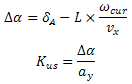
과소조향계수 추정부(230)는 수학식 1과 같이 차속 추정부(220)에서 추정된 종방향 차속 ![]()
![]()
![]()
![]()
![]()
![]()
![]()
![]()
![]()
![]()

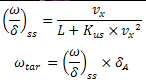
목표 요속도 추정부(240)는 수학식 2와 같이 차속 추정부(220)에서 추정된 종방향 차속 ![]()
![]()
![]()
![]()
![]()
![]()
![]()
![]()
![]()
![]()
요속도 오차 연산부(250)는 수학식 3과 같이 목표 요속도 추정부(240)에서 추정된 목표 요속도 ![]()
![]()
![]()
![]()
![]()
![]()
![]()
![]()
![]()
![]()

여기서, dz은 중립 주행상태에서의 최대 편차 ![]()
![]()
![]()
![]()
![]()
![]()
![]()
![]()
![]()
![]()
현재 요속도와 목표 요속도 사이에서의 편차 ![]()
![]()
![]()
![]()
![]()
![]()
![]()
![]()
요댐핑 제어기(260)는 수학식 4와 같이 요속도 오차 연산부(250)에서 산출된 요속도 오차 ![]()
![]()
![]()
![]()
![]()
![]()
![]()
![]()
이와 같이 제어부(200)는 차량거동과 운전자의 조향의지의 간격을 과소조향계수 ![]()
![]()
![]()
![]()
![]()
![]()
![]()
![]()
상술한 바와 같이, 본 발명의 실시예에 의한 전자식 LSD의 제어장치에 따르면, 전륜 차량의 고속 주행 중 급격한 조향시 요 댐핑을 제어하여 구동축의 강성을 높이고 차량의 거동변화를 둔감하게 하여 안정성을 향상시켜 보다 편한 운전 환경을 제공할 수 있다. As described above, according to the control system of the electronic LSD according to the embodiment of the present invention, it is possible to improve the rigidity of the drive shaft by controlling the damping in the sudden steering during high-speed running of the front wheel drive, So that a more comfortable operating environment can be provided.
도 2는 본 발명의 일 실시예에 따른 전자식 LSD의 제어방법을 설명하기 위한 흐름도이다. 2 is a flowchart illustrating a method of controlling an electronic LSD according to an embodiment of the present invention.
도 2에 도시된 바와 같이 본 발명의 일 실시예에 따른 전자식 LSD의 제어방법에서는 먼저, 제어부(200)가 차량거동 수집부(100)로부터 차량 거동정보를 수집한다(S10). As shown in FIG. 2, in the control method of the electronic LSD according to the embodiment of the present invention, the
차량 거동정보에는 운전자의 조향의지가 반영된 조향 핸들각 ![]()
![]()
![]()
![]()
![]()
![]()
![]()
![]()
![]()
![]()
![]()
![]()
S10 단계에서 차량 거동정보를 수집한 후 제어부(200)는 차량거동 수집부(100)로부터 수집된 조향 핸들각 ![]()
![]()
![]()
![]()
![]()
![]()
![]()
![]()
S20 단계에서 전륜 바퀴의 회전각 ![]()
![]()
![]()
![]()
![]()
![]()
![]()
![]()
![]()
![]()
![]()
![]()
![]()
![]()
![]()
![]()
여기서 종방향 차속 ![]()
![]()
이와 같이 추종된 종방향 차속 ![]()
![]()
![]()
![]()
![]()
![]()
S30 단계에서 종방향 차속 ![]()
![]()
![]()
![]()
![]()
![]()
![]()
![]()
![]()
![]()
![]()
![]()
S40 단계에서 과소조향계수 ![]()
![]()
![]()
![]()
![]()
![]()
![]()
![]()
![]()
![]()
![]()
![]()

S50 단계에서 목표 요속도 ![]()
![]()
![]()
![]()
![]()
![]()
![]()
![]()
![]()
![]()
![]()
![]()

여기서, dz은 중립 주행상태에서의 최대 편차 ![]()
![]()
![]()
![]()
![]()
![]()
![]()
![]()
![]()
![]()
현재 요속도와 목표 요속도 사이에서의 편차 ![]()
![]()
![]()
![]()
![]()
![]()
![]()
![]()
S60 단계에서 요속도 오차 ![]()
![]()
![]()
![]()
![]()
![]()
![]()
![]()
![]()
![]()
S70 단계에서 요댐핑 목표토크 ![]()
![]()
이와 같이 제어부(200)는 차량거동과 운전자의 조향의지의 간격을 과소조향계수 ![]()
![]()
![]()
![]()
![]()
![]()
![]()
![]()
상술한 바와 같이, 본 발명의 실시예에 의한 전자식 LSD의 제어방법에 따르면, 전륜 차량의 고속 주행 중 급격한 조향시 요 댐핑을 제어하여 구동축의 강성을 높이고 차량의 거동변화를 둔감하게 하여 안정성을 향상시켜 보다 편한 운전 환경을 제공할 수 있다. As described above, according to the control method of the electronic LSD according to the embodiment of the present invention, it is possible to improve the rigidity of the drive shaft by controlling the damping in the sudden steering during high speed running of the front wheel drive, So that a more comfortable operating environment can be provided.
본 발명은 도면에 도시된 실시예를 참고로 하여 설명되었으나, 이는 예시적인 것에 불과하며, 당해 기술이 속하는 분야에서 통상의 지식을 가진 자라면 이로부터 다양한 변형 및 균등한 타 실시예가 가능하다는 점을 이해할 것이다. While the present invention has been particularly shown and described with reference to exemplary embodiments thereof, it will be understood by those of ordinary skill in the art that various changes in form and details may be made therein without departing from the spirit and scope of the invention as defined by the appended claims. I will understand.
따라서 본 발명의 진정한 기술적 보호범위는 아래의 청구범위에 의해서 정하여져야 할 것이다.Accordingly, the true scope of the present invention should be determined by the following claims.
10 : 감지장치 20 : 차량제어장치
100 : 차량거동 수집부 200 : 제어부
210 : 휠각 연산부 220 : 차속 추정부
230 : 과소조향계수 추정부 240 : 목표 요속도 추정부
250 : 요속도 오차 추정부 260 : 요댐핑 제어기
300 : 차동제한 구동부10: sensing device 20: vehicle control device
100: vehicle behavior collecting unit 200:
210: a wheel angle calculation unit 220:
230: excess steering factor estimator 240: target yaw rate estimator
250: yaw rate error estimator 260: yaw damping controller
300: Differential limiting driver
Claims (7)
차륜의 토크를 각각 제어하는 차동제한 구동부; 및
상기 차량거동 수집부로부터 수집된 운전자의 조향상태와 차량의 거동상태를 기반으로 과소조향계수를 추정하여 요속도 오차를 산출하고, 상기 요속도 오차로부터 요댐핑 목표토크를 산출하여 상기 차동제한 구동부를 제어하는 제어부;를 포함하는 것을 특징으로 하는 전자식 LSD의 제어장치.
A vehicle behavior collector for collecting vehicle behavior information from the in-vehicle sensing apparatus and the vehicle control apparatus;
A differential limiting driver for controlling the torque of the wheel; And
Calculating a yaw damping target torque from the yaw rate error by estimating a subordinate steering coefficient based on a driver's steering state and a vehicle behavior state collected from the vehicle behavior collecting unit, And a controller for controlling the operation of the electronic LSD.
상기 차량거동 수집부로부터 수집된 차륜별 속도, 차량 제동상태, 종가속도, 횡가속도 및 현재 요속도와, 상기 휠각 연산부에서 산출된 상기 전륜 좌측 바퀴의 회전각 및 상기 전륜 우측 바퀴의 회전각을 기반으로 종방향 차속을 추정하는 차속 추정부;
상기 차속 추정부에서 추정된 상기 종방향 차속, 상기 휠각 연산부에서 산출한 상기 전륜 바퀴의 회전각, 전륜과 후륜의 슬립각 편차, 차량의 휠베이스 길이 및 상기 횡가속도를 기반으로 과소조향계수를 추정하는 과소조향계수 추정부;
상기 차속 추정부에서 추정된 상기 종방향 차속, 상기 과소조향계수 및 상기 차량의 휠베이스 길이를 기반으로 산출된 정상상태 선회의 요속도 게인과 상기 전륜 바퀴의 회전각을 기반으로 목표 요속도를 추정하는 목표 요속도 추정부;
상기 목표 요속도 추정부에서 추정된 상기 목표 요속도와 현재 요속도와의 편차 및 상기 목표 요속도와 상기 현재 요속도의 상태에 따라 부호를 설정하여 상기 요속도 오차를 산출하는 요속도 오차 연산부; 및
상기 요속도 오차 연산부에서 산출된 상기 요속도 오차에 제어 옵셋 보정치를 반영하여 비례제어를 통해 상기 요댐핑 목표토크를 산출하는 요댐핑 제어기;를 포함하는 것을 특징으로 하는 전자식 LSD의 제어장치.
The vehicle steering apparatus according to claim 1, wherein the controller calculates a rotation angle of the front wheel left wheel and a front wheel right wheel through the steering wheel angle collected from the vehicle behavior collecting unit and calculates a rotation angle of the front wheel, ;
A vehicle braking state, a closing speed, a lateral acceleration, a current yaw rate, a rotation angle of the front wheel left wheel and a rotation angle of the front right wheel calculated from the wheel angle calculating unit, A vehicle speed estimator for estimating a longitudinal vehicle speed;
Estimating an understeering coefficient based on the longitudinal vehicle speed estimated by the vehicle speed estimating unit, the rotational angle of the front wheel calculated by the wheel angle calculating unit, the slip angle deviation of front and rear wheels, the wheelbase length of the vehicle, A hypothetical steering coefficient estimator;
Estimating a target yaw rate based on the yaw rate gain of the steady state turning calculated on the basis of the longitudinal vehicle speed, the understeering coefficient and the wheelbase length of the vehicle estimated by the vehicle speed estimating unit and the rotational angle of the front wheel, A target yaw rate estimating unit;
A yaw rate error arithmetic unit for calculating a yaw rate error by setting a sign according to a deviation between the target yaw rate estimated by the target yaw rate estimator and the current yaw rate and a state of the target yaw rate and the current yaw rate; And
And a yaw damping controller for calculating the yaw damping target torque through proportional control by reflecting the control offset correction value to the yaw rate error calculated by the yaw rate error calculation unit.
The vehicle steering apparatus according to claim 2, wherein the wheel angle calculation unit calculates a rotation angle of the front wheel left wheel and a rotation angle of the front wheel right wheel from the steering wheel angle and calculates a rotation angle of the front wheel through a bicycle model of the vehicle And a control unit for controlling the electronic LSD.
The vehicle speed estimating apparatus according to claim 2, wherein the vehicle speed estimating unit estimates the longitudinal vehicle speed at a value that is the smallest among the relative speeds relative to the vehicle center of gravity of the respective wheels when the vehicle is not braked, And estimates the longitudinal vehicle speed at a maximum value of the relative speed with respect to the center of gravity of the vehicle.
상기 제어부가 수집된 조향 핸들각을 통해 전륜 좌측 바퀴의 회전각 및 전륜 우측 바퀴의 회전각을 연산하고, 전륜 바퀴의 회전각을 산출하는 단계;
상기 제어부가 수집된 차륜별 속도, 차량 제동상태, 종가속도, 횡가속도, 현재 요속도, 상기 전륜 좌측 바퀴의 회전각 및 상기 전륜 우측 바퀴의 회전각을 기반으로 종방향 차속을 추정하는 단계;
상기 제어부가 추정된 상기 종방향 차속, 상기 전륜 바퀴의 회전각, 전륜과 후륜의 슬립각 편차, 차량의 휠베이스 길이 및 상기 횡가속도를 기반으로 과소조향계수를 추정하는 단계;
상기 제어부가 추정된 상기 종방향 차속, 상기 과소조향계수 및 상기 차량의 휠베이스 길이를 기반으로 산출된 정상상태 선회의 요속도 게인과 상기 전륜 바퀴의 회전각을 기반으로 목표 요속도를 추정 단계;
상기 제어부가 추정된 상기 목표 요속도와 현재 요속도와의 편차 및 상기 목표 요속도와 상기 현재 요속도의 상태에 따라 부호를 설정하여 요속도 오차를 산출 단계;
상기 제어부가 산출된 상기 요속도 오차에 제어 옵셋 보정치를 반영하여 비례제어를 통해 요댐핑 목표토크를 산출 단계; 및
상기 제어부가 산출된 상기 요댐핑 목표토크를 통해 차동제한 구동부를 제어하는 단계;를 포함하는 것을 특징으로 하는 전자식 LSD의 제어방법.
The control unit collecting vehicle behavior information;
Calculating a rotation angle of the front wheel left wheel and a front wheel right wheel through the collected steering wheel angle, and calculating a rotational angle of the front wheel;
Estimating a longitudinal vehicle speed based on the collected velocity of the wheel, the vehicle braking state, the closing speed, the lateral acceleration, the current yaw rate, the rotational angle of the front wheel left wheel, and the rotational angle of the front right wheel;
Estimating an understeering coefficient based on the estimated longitudinal vehicle speed, the rotational angle of the front wheel, the slip angle deviation of the front wheel and the rear wheel, the wheel base length of the vehicle, and the lateral acceleration;
Estimating a target yaw rate on the basis of a yaw rate gain of a steady state turning calculated on the basis of the estimated longitudinal vehicle speed, the understeering coefficient, and a wheel base length of the vehicle, and a rotational angle of the front wheel;
Calculating a yaw rate error by setting a sign in accordance with the deviation between the target yaw rate and the current yaw rate estimated by the control unit and the state of the target yaw rate and the current yaw rate;
Calculating a yaw damping target torque through proportional control by reflecting a control offset correction value to the yaw rate error calculated by the controller; And
And controlling the differential limiting driver through the damping target torque calculated by the controller.
6. The method according to claim 5, wherein the step of calculating the rotational angle of the front wheel calculates the rotational angle of the front wheel left wheel and the rotational angle of the front right wheel from the steering wheel angle, And the rotation angle of the front wheel is calculated through the calculation of the rotation angle of the front wheel.
Priority Applications (1)
| Application Number | Priority Date | Filing Date | Title |
|---|---|---|---|
| KR1020170138964A KR101976276B1 (en) | 2017-10-25 | 2017-10-25 | Control apparatus of electronic limited slip differential and control method thereof |
Applications Claiming Priority (1)
| Application Number | Priority Date | Filing Date | Title |
|---|---|---|---|
| KR1020170138964A KR101976276B1 (en) | 2017-10-25 | 2017-10-25 | Control apparatus of electronic limited slip differential and control method thereof |
Publications (2)
| Publication Number | Publication Date |
|---|---|
| KR20190045968A KR20190045968A (en) | 2019-05-07 |
| KR101976276B1 true KR101976276B1 (en) | 2019-05-08 |
Family
ID=66580066
Family Applications (1)
| Application Number | Title | Priority Date | Filing Date |
|---|---|---|---|
| KR1020170138964A Active KR101976276B1 (en) | 2017-10-25 | 2017-10-25 | Control apparatus of electronic limited slip differential and control method thereof |
Country Status (1)
| Country | Link |
|---|---|
| KR (1) | KR101976276B1 (en) |
Cited By (1)
| Publication number | Priority date | Publication date | Assignee | Title |
|---|---|---|---|---|
| KR102835701B1 (en) | 2024-10-18 | 2025-07-18 | (주)한아기계 | Zig apparatus for fixing magnet of electric motor |
Families Citing this family (1)
| Publication number | Priority date | Publication date | Assignee | Title |
|---|---|---|---|---|
| KR102694446B1 (en) | 2021-12-15 | 2024-08-14 | 현대위아 주식회사 | Drift driving control method and system by electronic limited slip differential |
Citations (3)
| Publication number | Priority date | Publication date | Assignee | Title |
|---|---|---|---|---|
| KR100548710B1 (en) | 2001-12-27 | 2006-02-02 | 도요다 지도샤 가부시끼가이샤 | Integrated Vehicle Control System |
| JP4207029B2 (en) | 2005-08-08 | 2009-01-14 | トヨタ自動車株式会社 | Vehicle behavior control device |
| JP4980168B2 (en) | 2007-08-01 | 2012-07-18 | 富士重工業株式会社 | Vehicle behavior control device |
Family Cites Families (2)
| Publication number | Priority date | Publication date | Assignee | Title |
|---|---|---|---|---|
| CN100408398C (en) * | 2003-10-28 | 2008-08-06 | 大陆-特韦斯贸易合伙股份公司及两合公司 | Method and system for improving driving performance of vehicle |
| KR20140121056A (en) * | 2013-04-05 | 2014-10-15 | 주식회사 만도 | Steering control apparatus and steering feature controlling method |
-
2017
- 2017-10-25 KR KR1020170138964A patent/KR101976276B1/en active Active
Patent Citations (3)
| Publication number | Priority date | Publication date | Assignee | Title |
|---|---|---|---|---|
| KR100548710B1 (en) | 2001-12-27 | 2006-02-02 | 도요다 지도샤 가부시끼가이샤 | Integrated Vehicle Control System |
| JP4207029B2 (en) | 2005-08-08 | 2009-01-14 | トヨタ自動車株式会社 | Vehicle behavior control device |
| JP4980168B2 (en) | 2007-08-01 | 2012-07-18 | 富士重工業株式会社 | Vehicle behavior control device |
Cited By (1)
| Publication number | Priority date | Publication date | Assignee | Title |
|---|---|---|---|---|
| KR102835701B1 (en) | 2024-10-18 | 2025-07-18 | (주)한아기계 | Zig apparatus for fixing magnet of electric motor |
Also Published As
| Publication number | Publication date |
|---|---|
| KR20190045968A (en) | 2019-05-07 |
Similar Documents
| Publication | Publication Date | Title |
|---|---|---|
| JP5830554B2 (en) | Control method for four-wheel steering vehicle | |
| CN101405176B (en) | Driver-specific vehicle subsystem control method and apparatus | |
| CN105857304B (en) | Based on four-wheel drive car Torque distribution control system | |
| JP2009530166A (en) | Driving style sensitive vehicle subsystem control method and apparatus | |
| WO2016158720A1 (en) | Driving force control device for electric vehicle | |
| JP2004224258A (en) | Braking control device | |
| CN110626418B (en) | Method for vehicle steering control | |
| JP2006117176A (en) | Vehicle turning behavior control device | |
| JP2014189253A (en) | Driving force distribution control device of four-wheel drive vehicle | |
| CN115946534A (en) | Vehicle anti-slip treatment method, device, vehicle, medium and program product | |
| JP5848149B2 (en) | Control device for controlling driving force acting on vehicle | |
| JP2011236810A (en) | Driving force control device of vehicle | |
| KR101976276B1 (en) | Control apparatus of electronic limited slip differential and control method thereof | |
| US7272478B2 (en) | Control system for active attenuation of torque-steer via electric power steering | |
| JP2008273289A (en) | Control device of hybrid car | |
| JP4443582B2 (en) | Understeer suppression device | |
| JP4950052B2 (en) | Method and apparatus for controlling the lock level of an electronically controllable differential lock mechanism | |
| JP6318795B2 (en) | Vehicle turning control device and vehicle turning control method | |
| JP5423606B2 (en) | Steering force control device | |
| JP2016215737A (en) | Road gradient estimation apparatus | |
| KR20210080659A (en) | Control apparatus and method of rear wheel steer | |
| KR20210017151A (en) | Electronic stability control method for vehicle | |
| JP2001033476A (en) | Method and apparatus for estimating slip angle of vehicle body | |
| JP2018129890A (en) | Output control device of vehicle | |
| JP3426512B2 (en) | Vehicle turning behavior state detection device |
Legal Events
| Date | Code | Title | Description |
|---|---|---|---|
| PA0109 | Patent application |
Patent event code: PA01091R01D Comment text: Patent Application Patent event date: 20171025 |
|
| PA0201 | Request for examination | ||
| PE0902 | Notice of grounds for rejection |
Comment text: Notification of reason for refusal Patent event date: 20190104 Patent event code: PE09021S01D |
|
| E701 | Decision to grant or registration of patent right | ||
| PE0701 | Decision of registration |
Patent event code: PE07011S01D Comment text: Decision to Grant Registration Patent event date: 20190424 |
|
| GRNT | Written decision to grant | ||
| PR0701 | Registration of establishment |
Comment text: Registration of Establishment Patent event date: 20190430 Patent event code: PR07011E01D |
|
| PR1002 | Payment of registration fee |
Payment date: 20190430 End annual number: 3 Start annual number: 1 |
|
| PG1501 | Laying open of application | ||
| PG1601 | Publication of registration | ||
| PR1001 | Payment of annual fee |
Payment date: 20220323 Start annual number: 4 End annual number: 4 |
|
| PR1001 | Payment of annual fee |
Payment date: 20230321 Start annual number: 5 End annual number: 5 |
|
| PR1001 | Payment of annual fee |
Payment date: 20240312 Start annual number: 6 End annual number: 6 |
|
| PR1001 | Payment of annual fee |
Payment date: 20250305 Start annual number: 7 End annual number: 7 |