KR101966168B1 - Eddy Current Inspection Apparatus for Nondestructive Test - Google Patents
Eddy Current Inspection Apparatus for Nondestructive Test Download PDFInfo
- Publication number
- KR101966168B1 KR101966168B1 KR1020170092885A KR20170092885A KR101966168B1 KR 101966168 B1 KR101966168 B1 KR 101966168B1 KR 1020170092885 A KR1020170092885 A KR 1020170092885A KR 20170092885 A KR20170092885 A KR 20170092885A KR 101966168 B1 KR101966168 B1 KR 101966168B1
- Authority
- KR
- South Korea
- Prior art keywords
- signal
- test piece
- phase difference
- multiplied
- type coil
- Prior art date
Links
- 238000012360 testing method Methods 0.000 title claims abstract description 106
- 238000007689 inspection Methods 0.000 title claims abstract description 38
- 230000007547 defect Effects 0.000 claims abstract description 69
- 238000003491 array Methods 0.000 claims abstract description 9
- 230000006698 induction Effects 0.000 claims abstract description 8
- 238000000034 method Methods 0.000 claims description 12
- 230000003321 amplification Effects 0.000 claims description 11
- 238000003199 nucleic acid amplification method Methods 0.000 claims description 11
- 230000002950 deficient Effects 0.000 claims description 6
- 238000009659 non-destructive testing Methods 0.000 claims description 4
- 238000001514 detection method Methods 0.000 abstract description 6
- 230000001066 destructive effect Effects 0.000 abstract description 3
- 239000000523 sample Substances 0.000 description 19
- 230000007797 corrosion Effects 0.000 description 9
- 238000005260 corrosion Methods 0.000 description 9
- 238000012546 transfer Methods 0.000 description 9
- 238000006243 chemical reaction Methods 0.000 description 6
- 238000011158 quantitative evaluation Methods 0.000 description 5
- 238000010586 diagram Methods 0.000 description 4
- 230000000694 effects Effects 0.000 description 4
- 230000005672 electromagnetic field Effects 0.000 description 4
- 230000004907 flux Effects 0.000 description 4
- 230000010354 integration Effects 0.000 description 4
- 230000008859 change Effects 0.000 description 3
- 238000005336 cracking Methods 0.000 description 3
- 238000007796 conventional method Methods 0.000 description 2
- 239000012530 fluid Substances 0.000 description 2
- 239000000463 material Substances 0.000 description 2
- 238000005259 measurement Methods 0.000 description 2
- 230000007246 mechanism Effects 0.000 description 2
- 239000002184 metal Substances 0.000 description 2
- 229910000975 Carbon steel Inorganic materials 0.000 description 1
- XUIMIQQOPSSXEZ-UHFFFAOYSA-N Silicon Chemical compound [Si] XUIMIQQOPSSXEZ-UHFFFAOYSA-N 0.000 description 1
- 238000005299 abrasion Methods 0.000 description 1
- 230000005540 biological transmission Effects 0.000 description 1
- 239000010962 carbon steel Substances 0.000 description 1
- 239000004020 conductor Substances 0.000 description 1
- 238000001816 cooling Methods 0.000 description 1
- 230000003247 decreasing effect Effects 0.000 description 1
- 230000006866 deterioration Effects 0.000 description 1
- 230000003628 erosive effect Effects 0.000 description 1
- 238000011156 evaluation Methods 0.000 description 1
- 230000005284 excitation Effects 0.000 description 1
- 238000009472 formulation Methods 0.000 description 1
- 230000014509 gene expression Effects 0.000 description 1
- 230000020169 heat generation Effects 0.000 description 1
- 238000010438 heat treatment Methods 0.000 description 1
- 238000001459 lithography Methods 0.000 description 1
- 238000012423 maintenance Methods 0.000 description 1
- 239000000203 mixture Substances 0.000 description 1
- 238000012986 modification Methods 0.000 description 1
- 230000004048 modification Effects 0.000 description 1
- 230000001151 other effect Effects 0.000 description 1
- 230000035515 penetration Effects 0.000 description 1
- 239000011148 porous material Substances 0.000 description 1
- 230000002265 prevention Effects 0.000 description 1
- 238000012545 processing Methods 0.000 description 1
- 239000004065 semiconductor Substances 0.000 description 1
- 229910052710 silicon Inorganic materials 0.000 description 1
- 239000010703 silicon Substances 0.000 description 1
- 239000007787 solid Substances 0.000 description 1
Images


Classifications
-
- G—PHYSICS
- G01—MEASURING; TESTING
- G01N—INVESTIGATING OR ANALYSING MATERIALS BY DETERMINING THEIR CHEMICAL OR PHYSICAL PROPERTIES
- G01N27/00—Investigating or analysing materials by the use of electric, electrochemical, or magnetic means
- G01N27/72—Investigating or analysing materials by the use of electric, electrochemical, or magnetic means by investigating magnetic variables
- G01N27/82—Investigating or analysing materials by the use of electric, electrochemical, or magnetic means by investigating magnetic variables for investigating the presence of flaws
- G01N27/90—Investigating or analysing materials by the use of electric, electrochemical, or magnetic means by investigating magnetic variables for investigating the presence of flaws using eddy currents
- G01N27/9006—Details, e.g. in the structure or functioning of sensors
-
- G—PHYSICS
- G01—MEASURING; TESTING
- G01N—INVESTIGATING OR ANALYSING MATERIALS BY DETERMINING THEIR CHEMICAL OR PHYSICAL PROPERTIES
- G01N27/00—Investigating or analysing materials by the use of electric, electrochemical, or magnetic means
- G01N27/72—Investigating or analysing materials by the use of electric, electrochemical, or magnetic means by investigating magnetic variables
- G01N27/82—Investigating or analysing materials by the use of electric, electrochemical, or magnetic means by investigating magnetic variables for investigating the presence of flaws
- G01N27/90—Investigating or analysing materials by the use of electric, electrochemical, or magnetic means by investigating magnetic variables for investigating the presence of flaws using eddy currents
- G01N27/904—Investigating or analysing materials by the use of electric, electrochemical, or magnetic means by investigating magnetic variables for investigating the presence of flaws using eddy currents with two or more sensors
-
- G—PHYSICS
- G01—MEASURING; TESTING
- G01N—INVESTIGATING OR ANALYSING MATERIALS BY DETERMINING THEIR CHEMICAL OR PHYSICAL PROPERTIES
- G01N27/00—Investigating or analysing materials by the use of electric, electrochemical, or magnetic means
- G01N27/72—Investigating or analysing materials by the use of electric, electrochemical, or magnetic means by investigating magnetic variables
- G01N27/82—Investigating or analysing materials by the use of electric, electrochemical, or magnetic means by investigating magnetic variables for investigating the presence of flaws
- G01N27/90—Investigating or analysing materials by the use of electric, electrochemical, or magnetic means by investigating magnetic variables for investigating the presence of flaws using eddy currents
- G01N27/9046—Investigating or analysing materials by the use of electric, electrochemical, or magnetic means by investigating magnetic variables for investigating the presence of flaws using eddy currents by analysing electrical signals
Landscapes
- Chemical & Material Sciences (AREA)
- Chemical Kinetics & Catalysis (AREA)
- Electrochemistry (AREA)
- Physics & Mathematics (AREA)
- Health & Medical Sciences (AREA)
- Life Sciences & Earth Sciences (AREA)
- Analytical Chemistry (AREA)
- Biochemistry (AREA)
- General Health & Medical Sciences (AREA)
- General Physics & Mathematics (AREA)
- Immunology (AREA)
- Pathology (AREA)
- Investigating Or Analyzing Materials By The Use Of Magnetic Means (AREA)
Abstract
비파괴 검사를 위한 와전류 검사 장치가 개시된다. 본 장치는 비파괴 검사의 검사 대상인 시험편의 내부에 삽입되어 시험편의 내벽에 유도전류를 인가하기 위한 보빈형 코일, 시험편의 레퍼런스인 무결함 시험편의 내부에 삽입되어 무결함 시험편의 내벽에 유도 전류를 인가하기 위한 참조 코일, 보빈형 코일의 내부에 배치되되, 행과 열을 포함하는 원통형 홀센서 배열 및 다중 주파수 중 하나 이상의 주파수를 선택하여 보빈형 코일 및 참조 코일에 교류 전원을 인가하고, 위상차를 달리하는 구형파 신호를 생성하며, 인가된 신호 및 상기 구형파 신호가 제1 승산되도록 제어하는 제어 모듈을 포함하며, 제어 모듈은 원통형 홀센서 배열의 복수의 열 중에서 원호 방향의 열이 순차적으로 선택되도록 구동 전원을 스위칭하여 인가하고, 인가된 신호에 생성된 상기 위상차를 달리하는 구형파가 제2 승산되도록 제어하며, 제1 승산된 신호 및 상기 제2 승산된 신호에 기초하되, 신호의 진폭 및 위상차의 분포를 이용하여 시험편의 결함을 검출할 수 있다. 이에 따라 결함 검출이 정확하게 수행될 수 있다.An eddy current inspection apparatus for non-destructive inspection is disclosed. This apparatus is a bobbin type coil inserted inside the test specimen to be inspected for the nondestructive inspection to apply an induction current to the inner wall of the specimen and inserted into the defectless specimen as a reference of the specimen to induce an induced current in the inner wall of the defect- A bobbin type coil and a cylindrical Hall sensor array disposed in the bobbin type coil and including a row and a column and a plurality of frequencies are selected to apply an alternating current power to the bobbin type coil and the reference coil, And a control module for controlling the first and second multipliers so that the applied signal and the square wave signal are multiplied by a first multiplication factor, wherein the control module controls the drive power source to sequentially select arrays in the arcuate direction among the plurality of arrays of the cylindrical hall sensor array, And the square wave having the different phase difference generated in the applied signal is multiplied by the second time And control, but based on the first multiplied signal and the second multiplied signal, it is possible to use the magnitude and distribution of the phase difference between the signals to detect defects on the specimen. Thus, defect detection can be accurately performed.
Description
본 개시는 비파괴 검사를 위한 와전류 검사 장치에 관한 것이다.This disclosure relates to an eddy current testing apparatus for non-destructive testing.
발전소에 구비된 열교환기는 유체의 열을 전열관(heat trasfer tube)의 전열면을 통해 열전달을 일으켜 가열, 냉각, 응축 등의 기능을 수행한다. 고온, 고압, 진동, 수화학 환경 하에서 장시간 활용한 열교환기 전열관 튜브는 부식, 점식, 침식, 공식, 마모, 감육, 피로균열, SCC(stress corrosion cracking), IASCC(irradiation assisted stress corrosion cracking) 등의 손상을 입을 수 있다. 이러한 손상에 기인하여 열교환기 본연의 기능을 수행하지 못할 경우, 발전소 정상운전에 지장을 초래할 수 있다. 따라서, 열교환기 전열관의 건전성 확인을 위한 비파괴검사가 발전소 계획, 예방, 및 정비 기간 동안 주기적으로 수행되고 있다. 이를 위한 와전류검사용 탐촉자(probe)가 전열관 내부에 삽입되어 비파괴검사가 수행될 수 있다.The heat exchanger installed in the power plant performs the function of heating, cooling, and condensing by causing the heat of the fluid to transfer heat through the heat transfer surface of the heat transfer tube. Heat exchanger tubes that have been used for a long time under high temperature, high pressure, vibration and hydrochemical environment are used for corrosion, denting, erosion, formulation, wear, thinning, fatigue cracking, stress corrosion cracking (SCC) and irradiation assisted stress corrosion cracking It can be damaged. Failure to perform the function of the heat exchanger due to such damage may interfere with normal operation of the power plant. Therefore, non-destructive testing for the integrity of the heat exchanger tube is periodically performed during the planning, prevention and maintenance of the power plant. For this purpose, a probe for an eddy current test can be inserted into the heat transfer tube and a non-destructive inspection can be performed.
다만, 종래기술의 경우 보빈형 탐촉자, 환형배열 탐촉자, 회전형 탐촉자 등을 이용하여 비파괴 검사가 수행되었다. 그러나, 종래기술에 비해 검사속도, 결함탐상능력 및 내구성이 보다 향상되고, 정량평가 기능을 수행하는 비파괴검사 기기의 대두가 요청된다.However, in the prior art, nondestructive inspection was performed using a bobbin type probe, an annular array probe, and a rotary type probe. However, the inspection speed, the defect inspection capability and the durability are further improved as compared with the prior art, and the nondestructive inspection device performing the quantitative evaluation function is required.
본 발명은 상술한 문제점을 해결하기 위해 안출된 것으로, 본 발명의 일 실시 예는 와전류의 진폭과 위상차의 분포를 실시간으로 측정하는 와전류 검사 장치를 제안한다. SUMMARY OF THE INVENTION The present invention has been made to solve the above-mentioned problems, and an embodiment of the present invention proposes an eddy current testing apparatus for measuring the amplitude and phase difference distribution of an eddy current in real time.
본 발명에서 이루고자 하는 기술적 과제들은 이상에서 언급한 기술적 과제들로 제한되지 않으며, 언급하지 않은 또 다른 기술적 과제들은 아래의 기재로부터 본 발명이 속하는 기술분야에서 통상의 지식을 가진 자에게 명확하게 이해될 수 있을 것이다.It is to be understood that both the foregoing general description and the following detailed description are exemplary and explanatory and are not restrictive of the invention, unless further departing from the spirit and scope of the invention as defined by the appended claims. It will be possible.
상기한 과제를 실현하기 위한 본 발명의 일 실시 예와 관련된 비파괴 검사를 위한 와전류 검사 장치는 상기 비파괴 검사의 검사 대상인 시험편의 내부에 삽입되어 상기 시험편의 내벽에 유도전류를 인가하기 위한 보빈형 코일; 상기 시험편의 레퍼런스인 무결함 시험편의 내부에 삽입되어 상기 무결함 시험편의 내벽에 유도 전류를 인가하기 위한 참조 코일; 상기 보빈형 코일의 내부에 배치되되, 행과 열을 포함하는 원통형 홀센서 배열; 및 다중 주파수 중 하나 이상의 주파수를 선택하여 상기 보빈형 코일 및 상기 참조 코일에 교류 전원을 인가하고, 위상차를 달리하는 구형파 신호를 생성하며, 인가된 신호 및 상기 구형파 신호가 제1 승산되도록 제어하는 제어 모듈;을 포함하며, 상기 제어 모듈은 상기 원통형 홀센서 배열의 복수의 열 중에서 원호 방향의 열이 순차적으로 선택되도록 구동 전원을 스위칭하여 인가하고, 인가된 신호에 생성된 상기 위상차를 달리하는 구형파가 제2 승산되도록 제어하며, 상기 제1 승산된 신호 및 상기 제2 승산된 신호에 기초하되, 신호의 진폭 및 위상차의 분포를 이용하여 상기 시험편의 결함을 검출할 수 있다.In order to accomplish the above object, an eddy current inspection apparatus for non-destructive inspection according to an embodiment of the present invention includes: a bobbin type coil inserted into a test piece to be inspected of the nondestructive inspection and applying an induced current to the inner wall of the test piece; A reference coil inserted into the defect-free test piece, which is a reference of the test piece, for applying an induced current to the inner wall of the defect-free test piece; A cylindrical Hall sensor array disposed within the bobbin type coil and including rows and columns; And a control unit for controlling the bipolar coil and the reference coil to apply an AC power to the bobbin type coil and the reference coil to generate a square wave signal having a different phase difference and to control the applied signal and the square wave signal to be first multiplied Wherein the control module switches and applies a drive power source so that arrays in the circumferential direction are successively selected from a plurality of columns of the cylindrical hall sensor array, and a rectangular wave having a different phase difference generated in the applied signal And a defect of the test piece can be detected based on the first multiplied signal and the second multiplied signal and using the distribution of the amplitude and the phase difference of the signal.
본 발명의 다양한 실시예에 따르면 아래와 같은 효과가 도출될 수 있다.According to various embodiments of the present invention, the following effects can be obtained.
우선, 회전체 구조가 아니라서 간단하면서, 기계적으로 내구성이 우수한 와전류 검사 장치가 제공될 수 있다.First, an eddy current inspecting apparatus which is not a rotating body structure but which is simple and mechanically excellent in durability can be provided.
또한, 상기 와전류 검사 장치가 제공됨으로써, 종래의 장비에서는 구현되지 못하였던 실시간으로 와전류의 진폭 및 위상차의 분포를 시각적으로 표시할 수 있다. Also, by providing the eddy current inspecting apparatus, it is possible to visually display the amplitude and phase difference distribution of the eddy current in real time which is not realized in the conventional equipment.
또한, 상기 와전류 검사 장치가 제공됨으로써, 보빈형 탐촉자, 회전형 탐촉자, 환형배열 탐촉자 등의 장점들이 모두 구현될 수 있다.Further, by providing the eddy current inspection apparatus, advantages such as a bobbin type probe, a rotary type probe, and an annular array type probe can be realized.
또한, 상기 와전류 검사 장치가 제공됨으로써, 소구경 열교환기 전열관의 결함이 자동으로 검출될 수 있다.Further, by providing the eddy current inspecting apparatus, defects in the small diameter heat exchanger heat transfer pipe can be automatically detected.
또한, 상기 와전류 검사 장치가 제공됨으로써, 결함의 위치, 형상, 크기 등이 자동으로 평가될 수 있다.Further, by providing the eddy current inspection apparatus, the position, shape, size, etc. of defects can be automatically evaluated.
또한, 상기 와전류 검사 장치가 제공됨으로써, 종래의 보빈형 와전류 탐촉자에 비하여, 결함의 존재에 기인한 전자기장의 왜곡 분포가 정량적으로 측정될 수 있으며, 부식, 마모, 균열이 판별될 수 있으며 정량적으로 평가될 수 있다.Further, by providing the eddy current inspection apparatus, the distortion distribution of the electromagnetic field due to the presence of defects can be quantitatively measured as compared with the conventional bobbin eddy current probe, and corrosion, wear and cracks can be discriminated and quantitatively evaluated .
또한, 상기 와전류 검사 장치가 제공됨으로써, 종래의 회전형 와전류 탐촉자에 비하여, 회전체를 포함하지 않는 구조임에도 불구하고, 고속으로 전자기장의 왜곡 분포가 정량적으로 측정될 수 있으며, 부식, 마모, 균열이 판별될 수 있고, 정량적으로 평가될 수 있으며 우수한 내구성이 제공될 수 있다.Further, by providing the eddy current inspecting apparatus, it is possible to quantitatively measure the distortion distribution of the electromagnetic field at a high speed, despite the structure not including the rotating body, as compared with the conventional rotary eddy current transducer, and the corrosion, Can be discriminated, quantitatively evaluated and excellent durability can be provided.
또한, 상기 와전류 검사 장치가 제공됨으로써 종래의 환형배열 와전류 탐촉자에 비하여 발열이 적으면서 공간분해능이 높으며, 고속으로 전자기장의 왜곡 분포가 정량적으로 측정될 수 있으며, 부식, 마모, 균열의 판별이 용이하며, 정량 평가가 수행될 수 있다.Further, by providing the eddy current inspecting apparatus, it is possible to quantitatively measure the distortion distribution of the electromagnetic field at a high speed and to detect corrosion, wear and cracks at a high speed with a low heat generation and a high spatial resolution as compared with the conventional annular eddy current transducer , A quantitative evaluation can be performed.
또한, 상기 와전류 검사 장치가 제공됨으로써, 종래의 환형 자기센서배열 탐촉자에 비하여, 결함의 위치가 내부인지 외부인지 정량적으로 평가될 수 있고, 축방향으로 상기 장치가 이동하지 않은 상태에서도 고속으로 전자기장의 왜곡 분포가 정량적으로 측정될 수 있으며, 부식, 마모, 균열의 판별이 용이하며, 정량적으로 평가될 수 있다.Further, by providing the eddy current inspecting apparatus, it is possible to quantitatively evaluate the position of the defect, either internally or externally, as compared with the conventional annular magnetic sensor array transducer, The distortion distribution can be measured quantitatively, and it is easy to discriminate between corrosion, wear and cracks, and can be evaluated quantitatively.
마지막으로, 상기 와전류 검사 장치가 제공됨으로써 종래의 실린더형 자기센서배열 탐촉자에 비하여, 결함의 위치가 내부인지 외부인지 정량적으로 평가될 수 있고, 주파수에 따른 전자기장의 왜곡 분포가 정량적으로 측정될 수 있으며, 부식, 마모, 균열의 판별이 용이하고, 정량적으로 평가될 수 있다.Lastly, by providing the eddy current inspecting apparatus, it is possible to quantitatively evaluate the position of a defect, either internally or externally, as compared with a conventional cylindrical magnetic sensor array transducer, and the distortion distribution of the electromagnetic field according to the frequency can be quantitatively measured , Corrosion, wear and cracks can be easily identified and quantitatively evaluated.
본 발명에서 얻은 수 있는 효과는 이상에서 언급한 효과들로 제한되지 않으며, 언급하지 않은 또 다른 효과들은 아래의 기재로부터 본 발명이 속하는 기술분야에서 통상의 지식을 가진 자에게 명확하게 이해될 수 있을 것이다.The effects obtained by the present invention are not limited to the above-mentioned effects, and other effects not mentioned can be clearly understood by those skilled in the art from the following description will be.
도 1은 본 발명의 일 실시 예에 따른 시험편에 삽입된 와전류 검사 장치의 탐촉자를 나타낸다.
도 2는 도 1에 도시된 탐촉자의 일부분을 구체적으로 확대한 도면이다.
도 3은 도 2에 도시된 보빈형 코일에 대응되는 참조 코일을 나타낸다.
도 4는 본 발명의 일 실시 예에 따른 다중 주파수 교류전원 인가회로를 나타낸다.
도 5는 본 발명의 일 실시 예에 따른 보빈형 코일 및 참조 코일을 이용하여 와전류의 신호를 취득하기 위한 회로를 나타낸다.
도 6은 본 발명의 일 실시 예에 따른 원통형 홀센서 배열을 이용하여 와전류의 신호를 취득하기 위한 회로를 나타낸다.
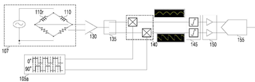
도 7은 본 발명의 일 실시 예에 따른 와전류 검사 장치의 구성을 나타낸는 블록도이다.
도 8(a) 및 도 8(b)는 본 발명의 일 실시 예에 따른 다양한 결함을 포함한 시험편을 나타낸다.
도 9 내지 도 12는 도 8에 도시된 시험편을 이용하여, 다중 주파수에 따른 진폭 분포 및 위상차 분포를 나타낸다.
도 13은 50kHz의 주파수를 인가하였을 때, 도 11과 도 12에서 결함의 중심을 지나는 센서의 출력을 바탕으로 도시한 리사주선도이다.
이상에서 살펴본 바와 같이 본 발명은 바람직한 실시예를 들어 도시하고 설명하였으나, 상기한 실시예에 한정되지 아니하며 본 발명의 정신을 벗어나지 않는 범위 내에서 당해 발명이 속하는 기술 분야에서 통상의 지식을 가진 자에 의해 다양한 변경과 수정이 가능할 것이다.1 shows a probe of an eddy current inspecting apparatus inserted into a test piece according to an embodiment of the present invention.
FIG. 2 is a partially enlarged view of a part of the probe shown in FIG. 1. FIG.
Fig. 3 shows a reference coil corresponding to the bobbin type coil shown in Fig.
4 shows a multi-frequency AC power supply circuit according to an embodiment of the present invention.
5 shows a circuit for acquiring an eddy current signal using a bobbin type coil and a reference coil according to an embodiment of the present invention.
6 shows a circuit for acquiring an eddy current signal using a cylindrical Hall sensor arrangement according to an embodiment of the present invention.
7 is a block diagram showing the configuration of an eddy current testing apparatus according to an embodiment of the present invention.
Figures 8 (a) and 8 (b) show test specimens comprising various defects according to an embodiment of the present invention.
9 to 12 show amplitude distribution and phase difference distribution according to multiple frequencies using the test piece shown in Fig.
FIG. 13 is a graph of the RISAS diagram based on the output of the sensor passing the center of the defect in FIGS. 11 and 12 when a frequency of 50 kHz is applied.
While the present invention has been particularly shown and described with reference to exemplary embodiments thereof, it is clearly understood that the same is by way of illustration and example only and is not to be taken by way of limitation, Various changes and modifications will be possible.
이하 첨부된 도면들을 참조하여 본 발명의 다양한 실시 예를 보다 상세하게 설명한다. 다만, 본 발명을 설명함에 있어서, 관련된 공지 기능 혹은 구성에 대한 구체적인 설명이 본 발명의 요지를 불필요하게 흐릴 수 있다고 판단되는 경우 그에 대한 상세한 설명은 생략한다.Various embodiments of the present invention will now be described in detail with reference to the accompanying drawings. In the following description of the present invention, a detailed description of known functions and configurations incorporated herein will be omitted when it may make the subject matter of the present invention rather unclear.
도 1은 본 와전류 검사 장치(도 7, 100)의 탐촉자(30)가 시험편(10)에 삽입된 예를 나타낸다. 이하의 설명시 도 7의 도면부호를 함께 차용하기로 한다.Fig. 1 shows an example in which a
비파괴 검사는 초음파, 와전류 등을 이용하여 시험편(10) 내부의 기공이나 균열 등의 결함 등을 시험편(10)을 파괴하지 않고 검사할 수 있다. 와전류(Eddy Current)란 도체표면에 가해지는 교류 자기장에 의한 유도전류이며, 와전류 검사 장치는 시험편(10)에 유도된 와전류를 측정하여 비파괴검사를 수행하는 장치이다. 또한, 프루브(probe)라고 불리는 탐촉자(30)는 비파괴검사를 수행하기 위한 검색 유닛(search unit)에 해당된다. The nondestructive inspection can be performed without destroying the
본 명세서에서는 원자력 발전소의 열교환기에 사용되는 유체의 열을 전달하는 전열관(heat trasfer tube)을 시험편(10)을 예를 들어 설명하나, 구현시에는 비파괴 검사의 대상인 다양한 오브젝트가 시험편(10)으로 이용될 수 있다.In this specification, a heat transfer tube (heat transfer tube) for transferring heat of a fluid used in a heat exchanger of a nuclear power plant is described as an example of a
탐촉자(30)는 원통형으로 구성될 수 있으며, 상기 탐촉자(30)는 탐촉자 기구(33), 상기 탐촉자 기구(33)에 감긴 보빈형 코일(110), 상기 보빈형 코일(110)의 내부에 배치된 원통형 홀센서 배열(120)을 포함할 수 있다. 탐촉자 기구(33)는 다양한 모양으로 구성될 수 있으나, 시험편(10)에 삽입될 때 장애물이 있는 경우 이를 감지하여 제어 모듈(도 7의 115)에 전달할 수 있다.The
이하에서는 도 1에 도시된 탐촉자(30)의 특정 부분(u)을 확대한 도 2를 참고하여 보다 구체적으로 설명하기로 한다. Hereinafter, the specific portion u of the
도 2에 따르면, 시험편(10)은 결함부위(13)를 포함할 수 있다. 결함부위(13)는 부식, 마모, 균열 등에 의해 생길 수 있고, 체적성 결함에 의해 발생될 수 있다.According to Fig. 2, the
상기 결합부위(13)를 정확하게 탐지하기 위해 상술한 와전류 검사 장치(100)가 제안된 것이고, 상기 와전류 검사 장치(100)는 보빈형 코일(110) 및 원통형 홀센서 배열(120)을 이용하여 결합부위(13)를 정확하게 검출할 수 있다.The eddy current inspecting
보빈형 코일(110)은 반지름 r인 광폭 보빈형 코일로 금속재질의 소구경 배관 시험편(10)의 내부에 삽입될 수 있다. 시험편(10)을 구경이 작은 소구경으로 설명하나, 구현시에는 시험편(10)이 대구경, 중구경을 가질 수 있다. The
보빈형 코일(110)에는 아래 [수학식 1]의 교류 전압이 인가될 수 있다.The AC voltage of the following formula (1) may be applied to the
[수학식 1][Equation 1]
![]()
![]()
여기서, 주파수는 식 ω=2πf에 의해 도출될 수 있으며, 와전류 검사 장치(도 7, 100)는 다중 주파수의 교류 전압을 보빈형 코일(110)에 인가할 수 있다. 가령, 와전류 검사 장치(100)는 30 KHz의 주파수를 보빈형 코일(110)에 인가할 수 있고, 50 KHz의 주파수를 보빈형 코일(110)에 인가할 수 있으며, 이들의 복합된 주파수를 인가할 수 있으나, 실시 예는 이에 국한되지 않는다. 다중 주파수를 인가하기 위해 별도의 다중 주파수 교류 전원 인가 회로가 포함될 수 있다.Here, the frequency can be derived by the equation ω = 2πf, and the eddy current testing apparatus (FIGS. 7 and 100) can apply the alternating voltage of multiple frequencies to the
이때, 보빈형 코일(110)에 교류전압이 인가되는 경우, 시험편(10) 내벽(inner diameter)에 유도전류의 흐름이 나타날 수 있다. 원통좌표계로서 반지름방향 r, 원호 방향 Φ, 축방향 z라 하고, 보빈형 코일(110)의 저항과 인덕턴스를 각각 R과 L이라고 하면 여자전류(exciting current)는 아래 [수학식 2]와 같이 도출될 수 있다. 또한, 이러한 보빈형 코일(110)의 여자전류는 z축 방향으로 [수학식 3]과 같은 자속을 발생시킨다.At this time, when an alternating voltage is applied to the
[수학식 2]&Quot; (2) "

[수학식 3]&Quot; (3) "
![]()
![]()
만약, 시험편(10)에 결함이 없을 때에는 상기 보빈형 코일(110)의 반대방향이면서 시험편(10)의 Φ 방향을 따라 [수학식 4]의 유도전류가 발생한다. 또한, 이러한 유도전류는 -z 방향으로 [수학식 5]와 같은 자속을 발생시킨다. 이때, d는 시험편(10, specimen)의 두께를 나타낸다.If there is no defect in the
[수학식 4] &Quot; (4) "

[수학식 5]&Quot; (5) "

따라서, 보빈형 코일(110)에는 [수학식 6]의 자속이 인가될 수 있다.Therefore, the magnetic flux of Equation (6) can be applied to the
[수학식 6]&Quot; (6) "
![]()
![]()
한편, 보빈형 코일(110)의 내부에는 원통형 홀센서 배열(120)이 배치될 수 있다. 복수의 홀센서가 원통형 모양을 따라 행과 열을 구성하여 배치될 수 있다. 또한, 열교환기 전열관이 곡관부의 형태를 가져서 센서의 전체 길이가 짧아져야 하는 경우에는 한 개의 열로 구성되어 환형으로 배치될 있다. 상기 원통형 홀센서 배열(120)는 회전하지 않고 고정되어 와전류 검사 장치의 내구성이 우수하게 된다.The cylindrical
시험편(10)의 유도전류가 왜곡되는 경우, 시간적으로 변화하는 자계(시변자계)도 왜곡되게 된다. 복수의 홀센서는 환형 또는 실린더 형태로 구성된 반도체 기반의 수동형 자기센서로 시변자계의 왜곡을 측정할 수 있다. 이에 따라, 복수의 홀센서는 시험편(10)의 결함의 존재 뿐만 아니라 시변자계의 세기를 측정할 수 있다. 이는 능동형 코일센서를 이용하는 경우보다 크기가 작고, 센서 간의 건섭이 없어 공간 분해능을 높을 뿐 아니라, 센서를 교차로 구동시킬 필요가 없다. 또한, 구현시에 상기 복수의 홀센서는 GMR(giant magnetoresistance) 센서로 대체될 수도 있다.When the induced current of the
도 3은 도 2에 도시된 보빈형 코일(110)에 대응되는 참조 코일(110r)을 나타낸다.FIG. 3 shows a
도 3에 도시된 시험편(20)은 무결함 시험편(20)이다. 무결함 시험편(20)은 시험편(10)과 동일 소재이고 시험편(10)의 레퍼런스이며 결함이 없는 것이 특징이다. 무결함 시험편(20) 내부에 상기 참조 코일(110r)이 배치될 수 있다. 참조코일(110r)에는 아래 수학식 7에 따른 자속이 인가될 수 있다.The
[수학식 7]&Quot; (7) "
![]()
![]()
도 4는 본 발명의 일 실시 예에 따른 다중 주파수 교류전원 인가회로를 나타낸다. 4 shows a multi-frequency AC power supply circuit according to an embodiment of the present invention.
도 4와 같이, 측정 시험편(10)에 내삽된 보빈형 코일(110) 및 무결함 시험편(20)에 내삽된 참조코일(110r)의 출력이 차동으로 연결될 수 있다. 구체적으로, 다중 주파수 교류전원 인가부(107)의 브릿지 회로의 일단에 보빈형 코일(110)이 배치되고, 다른 일단에 참조 코일(110r)이 배치되며 두 개의 저항이 각각 배치될 수 있다. The output of the
다중 주파수 교류전원 인가부(107)는 후술할 제어 모듈(115)의 제어에 따라 복수의 주파수 중 선택된 주파수로 교류전원이 인가될 수 있다. 이때, 보빈형 코일(110) 및 참조 코일(110r)의 출력이 차동으로 연결되면, 출력신호는 [수학식 6] 및 [수학식 7]을 이용하여 아래 [수학식 8]과 같이 표현될 수 있다. 여기서, reference는 참조 코일(110r), specimen은 보빈형 코일(110)을 나타낸다.The multi-frequency AC
[수학식 8]&Quot; (8) "

만약, 시험편(10)에 결함이 존재하지 않는 경우에는 [수학식 8]의 Ψ에 의한 출력전류는 0 이다. 하지만, 시험편(10)에 결함이 존재하는 경우에는 Ψ가 0이 아니며, 결함의 위치 및 크기에 따라 [수학식 9]와 [수학식 10]으로 표현되는 임피던스 및 위상차가 변화한다.If there is no defect in the
[수학식 9]&Quot; (9) "
![]()
![]()
[수학식 10]&Quot; (10) "

편의상 결함이 있는 경우에 출력되는 전류를 [수학식 9]와 [수학식 10]을 이용하여 아래 [수학식 11]과 같이 도출될 수 있다. 여기서, crack은 결함을 나타낸다.For convenience, the output current may be derived using Equation (9) and Equation (10) as Equation (11) below. Here, crack indicates a defect.
[수학식 11] &Quot; (11) "

도 5는 본 발명의 일 실시 예에 따른 보빈형 코일(110) 및 참조 코일(110r)을 이용하여 와전류의 신호를 취득하기 위한 회로를 나타낸다. 다만, 구현시에는 상기 참조코일(110r)이 회로에서 생략될 수 있으며, 상기 무결함 시험편(20)도 생략될 수 있다.5 shows a circuit for acquiring an eddy current signal using the
와전류 검사 장치(100)는 보빈형 코일(110)과 참조코일(110r)의 차동 신호선을 코일센서 출력용 교류증폭회로(130)에 연결하여 충분한 신호레벨로 증폭할 수 있다. 와전류 검사 장치(100)는 증폭된 신호레벨을 코일센서 출력용 분기회로(135)에 의하여 분기할 수 있다. 또한, 와전류 검사 장치(100)는 각각의 분기신호를 코일센서 출력용 승산회로(140)를 이용하여 위상지연 구형파 회로(105)의 신호(105a)와 승산하는 경우, 상기 [수학식 11]을 아래의 [수학식 12] 및 [수학식 13]으로 도출할 수 있다. 여기서, 위상지연 구형파 회로(105)는 90도의 위상차를 가지는 신호를 코일센서 출력용 승산회로(140)에 제공할 수 있다. The eddy
[수학식 12]&Quot; (12) "

[수학식 13]&Quot; (13) "

와전류 검사 장치(100)는 승산된 신호 각각을 코일센서 출력용 적분회로(145)에 의하여 적분할 수 있다. 와전류 검사 장치(100)는 제어 모듈(115)을 이용하여 보빈형 코일(110)의 신호연산을 수행하는데 있어 신호를 복소수 평면의 실수부와 허수부로 표현할 수 있다. The eddy
즉, 상기 [수학식 12] 및 [수학식 13]의 각 변을 제곱하여 더한 후 제곱근 연산을 수행한 경우, 아래 [수학식 14]와 같은 임피던스의 차이가 도출될 수 있다. 시험편(10)에 결함이 존재하는 경우, 유도전류의 임피던스가 증가하게 된다.That is, when the sides of Equations (12) and (13) are squared and then the square root operation is performed, a difference in impedance as shown in the following Equation (14) can be derived. If there is a defect in the
[수학식 14]&Quot; (14) "

또한, 나눗셈 연산을 수행하는 경우, 아래 [수학식 15]와 같은 위상차가 도출될 수 있다. 상기 위상차에 기초하여 시험편(10)의 내벽(ID, inner diameter) 또는 외벽(OD, outer diameter)에 결함이 발생되었는지 검출될 수 있다.Further, when performing the division operation, the phase difference as shown in the following equation (15) can be derived. It can be detected based on the phase difference whether a defect has occurred in the inner diameter (ID), outer diameter (OD) or outer diameter (OD) of the
[수학식 15]&Quot; (15) "

이와 같이 와전류 검사 장치(100)는 시험편(10)의 어떤 위치에 결함이 발생되었는지 임피던스의 차이 및 위상차에 기초하여 검출할 수 있다.Thus, the eddy
한편, 도 6은 본 발명의 일 실시 예에 따른 원통형 홀센서 배열(120)을 이용하여 와전류의 신호를 취득하기 위한 회로를 나타낸다.Meanwhile, FIG. 6 shows a circuit for acquiring an eddy current signal using the cylindrical
와전류 검사 장치(100)는 원통형 홀센서배열(120)를 이용하여 신호를 취득할 수 있다. 와전류 검사 장치는 반지름 r인 광폭 보빈형 코일(110)이 금속재질의 소구경 배관 시험편(10)에 내삽되고, 식 ω=2πf에 의해 도출되는 주파수로 교류전압이 인가되었을 때, 시험편 내벽에 발생되는 유도전류는 결함 근방에서 왜곡된다. 따라서, z방향의 교번자계와 함께 r 방향의 교번자계가 발생된다. 여기서, 교번자계는 세기기 시간과 더불어 양 또는 음의 방향으로 증감하고 방향을 바꾸지 않는 자계를 말한다.The eddy
이러한 교번자계를 측정하기 위하여 와전류 검사 장치(100)는 자기센서 구동전원 스위칭회로(190)를 동작시켜, 원통형 홀센서배열(120)의 Φ 방향의 1개 열(120-1 내지 120-4 각각)에 전원을 공급한다. 원통형 홀센서배열(120)은 도 6에 도시된 4개의 열(120-1 내지 120-4)보다 더 많은 열을 포함될 수 있으며, 센서의 전체 길이가 짧아져야 할 경우에는 한 개의 열로 구성되어 환형으로 배치될 수 있다. In order to measure such an alternating magnetic field, the eddy
또한, 상기 와전류 검사 장치(100)는 z 방향의 각각의 센서 배열의 신호선을 자기센서 출력용 병렬형 교류증폭회로(160)에 연결하여 충분한 신호레벨로 증폭한 후, 자기센서 출력용 병렬형 분기회로(165)에 의하여 분기할 수 있다. Further, the eddy
또한, 상기 와전류 검사 장치(100)는 각각의 분기신호를 자기센서 출력용 승산회로(170)를 이용하여 위상지연 구형파 회로(105)의 구형파 신호(105a) 및 분기신호가 승산될 수 있다. 이에 따라, 와전류 검사 장치(100)는 상술한 [수학식 12 내지 15] 와 같이 결함의 존재에 기인한 r 방향 교번자계의 진폭 및 위상차를 측정할 수 있다. 이때 각각의 진폭 및 위상차는 환형배열형 자기센서 신호연산 부(115b2)에 의하여 소프트웨어적으로 계산될 수 있고, 구현시에는 하드웨어적으로도 계산될 수 있다.The eddy
도 6에 따르면, 시험편(10)의 결함이 체적성 결함인지 균열성 결함인지 평가될 수 있어, 발전소 정상 출력운전 중 전열관 파열에 의한 누설발생의 위험성이 해소될 수 있다. 또한, 원통형 홀센서배열(120)이 삽입되어 멈춰 있더라도, 기계적 회전을 하지 않은 상태에서 시변자계의 분포를 측정할 수 있으므로 장비의 열화를 방지할 수 있다. 또한, 전자식 스캔에 의하여 결함 검출 및 평가 속도가 빠르게 될 수 있다. 또한 원통형 홀센서배열(120)이 복수의 열로 구성되고 각 열이 환형 모양인 바, 하나의 열만 선택힌 후 축방향으로 결함을 스캔하여 빠른 속도로 결함유무 판별 및 정량 평가에 사용될 수 있다. 또한, 홀센서 자체가 능동형 코일 센서가 아니고 크기가 작으므로, 센서의 상호 간섭이 문제되지 않으며, 비용이 저렴하게 될 수 있고, 공간 분해 능력이 우수하게 된다. 또한, 시험편(10)의 축방향으로 일부 영역만큼만 스캔이 수행될 수 있으며, 결함으로 인한 사변 자계가 왜곡되는 경우 결함 유무, 결함의 형상 및 크기 등이 모두 정량적으로 정확하게 평가될 수 있다. 또한, 다중 주파수를 이용하여 결함 검출이 가능하여 결함의 정량 평가에 탁월한 효과가 발생될 수 있다.According to Fig. 6, it can be evaluated whether the defects of the
이하에서는 도 7을 참고하여 본 발명의 일 실시 예에 따른 와전류 검사 장치(100)의 구성을 나타내는 블록도이다. 와전류 검사 장치(100)는 코일(110, 110r) 센싱에 기반한 결함 검출 및 원통형 홀센서 배열(120)을 이용한 결함 검출을 모두 제공할 수 있다. Hereinafter, referring to FIG. 7, a block diagram illustrating a configuration of an eddy
우선 코일(110, 110r) 센싱을 먼저 기술하기로 한다.First, the sensing of the
와전류 검사 장치(100)는 다중 주파수를 인가하는 다중 주파수 교류 전원 인가부(107)를 포함할 수 있다. 와전류 검사 장치(100)의 제어 모듈(115)은 상기 다중 주파수 교류 전원 인가부(107)에 복수의 주파수가 인가될 수 있도록 제어할 수 있다.The eddy
와전류 검사 장치(100)는 인가된 교류 전류에 코일센서 출력용 교류증폭 회로(130), 코일센서 출력용 분기회로(135)에서 출력된 신호와 위상지연 구형파 회로(105)에서 90도 위상차를 두는 구형파 신호를 코일센서 출력용 승산회로(140)에서 승산할 수 있다. The eddy
승산된 신호는 코일센서 출력용 적분회로(145) 및 코일센서 출력용 직류 증폭 회로(150)를 거쳐 AD 변환회로(155)에 의해 아날로그 신호가 디지털신호로 변환될 수 있다.The multiplied signal can be converted into a digital signal by the
이때, 제어 모듈(115)의 보빈형 코일센서 신호 연산부(115b1)은 코일센서 출력용 직류증폭회로(150)로부터 출력된 2개의 신호를 조합하여 결함 유무와 위치에 따른 진폭과 위상차를 계산할 수 있다. At this time, the bobbin type coil sensor signal operating unit 115b1 of the
그 다음, 코일(110, 110r) 센싱에 이어 원통형 홀센서 배열(120)을 이용한 결함 검출을 설명하기로 한다.Next, the detection of defects using the cylindrical
먼저, 와전류 검사 장치(100)는 원통형 홀센서 배열(120)의 각 열(120-1, 120-2, 120-3, 120-4 등)에 구동전원을 선택적으로 인가하는 자기센서 구동전원 스위칭 회로(190)를 통해 축방향으로 순차적으로 전원을 인가할 수 있다. 구현시에는 축방향에만 국한되지는 않고, 결함을 발견하는 부위를 기준으로 앞뒤로 전원이 순차적으로 인가될 수도 있다.The eddy
와전류 검사 장치(100)는 인가된 신호가 자기센서 출력용 교류증폭회로(160), 자기센서 출력용 병렬형 분기회로(165)을 통해 출력되도록 제어할 수 있다.The eddy
이때, 분기회로(165)에서 출력된 신호는 위상지연 구형파 회로(105)의 구형파 신호와 자기센서 출력용 승산회로(170)를 통해 승산될 수 있다. 상기 구형파 신호는 코일센서(110, 110r)에서 사용한 구형파 신호일 수 있으며, 90도의 위상차를 가지게 되나, 구현시에는 다른 각도의 위상차도 가능하다.At this time, the signal output from the
승산된 신호는 자기센서 출력용 적분회로(175), 자기센서 출력용 직류증폭회로(180)를 거쳐 AD 변환회로(155)에 의해 아날로그 신호가 디지털 신호로 바뀔 수 있다.The multiplied signal can be converted into a digital signal by the
이때, 제어 모듈(115)의 환형 배열형 자기센서 신호 연산부(115b2)는 자기센서 출력용 직류증폭회로(180)로부터 출력된 열방향 센서수의 2배에 해당되는 신호를 조합하여 결함 유무와 위치에 따른 진폭과 위상차의 분포를 계산할 수 있다.At this time, the annular array type magnetic sensor signal calculator 115b2 of the
그리고, 상기 보빈형 코일센서 신호연산부(115b1)와 환형 배열형 자기센서 신호연산부(115b2)는 각각 코일센서 출력용 적분회로(145)를 거쳐서 출력된 2개의 적분신호를 증폭하기 위한 코일센서 출력용 직류증폭회로(150)와, 자기센서 출력용 적분회로(175)를 통과하여 출력된 센서 1개당 2개씩의 적분신호를 증폭하기 위한 자기센서 출력용 직류증폭회로(180)와, 상기 자기센서 출력용 직류증폭회로(180)와 코일센서 출력용 직류증폭회로(150)에서 출력된 아날로그 신호를 디지털신호로 변환하기 위한 AD변환회로(155)를 거쳐서 연산장치에 입력된 후에 구동될 수 있다.The bobbin type coil sensor signal computing unit 115b1 and the annular array type magnetic sensor signal computing unit 115b2 are respectively connected to a coil sensor
또한, 실린더 배열형 자기센서 신호 연산부(115b3)는 다중 주파수 교류전원 인가부(107)의 특정주파수를 선택한 상태에서, 상기 원통형 홀센서 배열(120)의 원호방향의 각 열을 순차적으로 선택하면서, 상기 자기센서 출력용 직류증폭회로(180)로부터 출력된 열방향 센서수의 2배에 해당하는 신호를 조합하여 결함 유무와 위치에 따른 진폭과 위상차의 분포를 계산할 수 있다.The cylinder array type magnetic sensor signal calculator 115b3 sequentially selects each column of the cylindrical
제어 모듈(115)은 다중주파수 교류전원 인가부(107)의 주파수 선택, 코일센서 출력용 교류증폭회로(130) 및 코일센서 출력용 직류증폭회로(150)의 증폭비 변환, 자기센서 구동전원 스위칭 회로(190)의 가동, 자기센서 출력용 교류증폭회로(160) 및 직류증폭회로(180)의 증폭비 변환, AD변환회로(155)의 구동, 보빈형 코일 센서 신호연산부(115b1), 환형 배열형 자기센서 신호연산부(115b2), 실린더 배열형 자기센서 신호 연산부(115b3)를 제어할 수 있다.The
도 8(a) 및 도 8(b)는 본 발명의 일 실시 예에 따른 다양한 결함을 포함한 시험편을 나타낸다.Figures 8 (a) and 8 (b) show test specimens comprising various defects according to an embodiment of the present invention.
도 7(a)에 따르면, 시험편(10)의 총 길이는 500 mm 이고, 각종 결함이 나타난다. 또한 시험편(10)과 별개로 결함이 없는 시험편(20)의 경우 시험편(10)의 결함이 존재하지 않는다.According to Fig. 7 (a), the total length of the
외벽(OD)은 15.87 이고, 원주 내경(ID)은 13.33 이며, 두께는 1.27 이고 소재는 SS304 로 이뤄진다. TSP(tube support plate)는 카본 스틸로 구성될 수 있으나, 구현시에 시험편(10)의 규격은 다양하게 바뀔 수 있다.The outer wall (OD) is 15.87, the circumferential inner diameter (ID) is 13.33, the thickness is 1.27, and the material is SS304. The TSP (tube support plate) may be made of carbon steel, but the dimensions of the
도 8(a)의 각각의 지점에 대해 결함에 대응되는 표는 도 8(b)에 나타난다.A table corresponding to the defect for each point in Fig. 8 (a) is shown in Fig. 8 (b).
FBH(flat bottomed hole)은 평저공이고, TWH(through wall hole)은 관통홀을 나타낸다. TSP(tube support plate)도 관측된다.A flat bottomed hole (FBH) is a flat bottom hole, and a through wall hole (TWH) is a through hole. TSP (tube support plate) is also observed.
도 9은 주파수 30 KHz가 인가된 경우의 각 결함의 진폭 분포를 나타낸다.9 shows the amplitude distribution of each defect when a frequency of 30 KHz is applied.
도 9에 따르면, 보빈형코일(110)에 주파수 30kHz가 인가되는 경우, 원통형 홀센서 배열(120) 중 선택된 하나의 환형열에서 측정한 시변자계 진폭의 분포가 나타난다. 횡축은 거리를 나타내며, 종축은 360도 방향으로 배열된 센서의 위치를 나타낸다. 연속된 그림에서 ID groove, OD groove, TSP와 같이 시험편의 원호방향으로 연속된 결함은 모든 센서에서 반응하므로, 종축으로 연속적으로 변화된 자계 분포를 나타낸다. FBH 20%-4는 4개의 FBH 결함이 환형으로 90도 간격으로 배열된 것으로, 진폭분포를 통해 결함이 90도 간격으로 배열된 것이 표시된다. 그리고, FBH 40~100%는 결함의 직경과 깊이가 서로 다른 결함을 나타낸다. 상하 4개씩 총 8개의 3차원 그래프는 상기 원통형 홀센서 배열(120)를 결함의 중심위치에 놓고, 환형으로 배열된 열을 순차적으로 선택하여 측정하였을 때 취득할 수 있는 시변자계의 진폭의 분포를 나타낸다. 즉, 종래의 기술에서 취득할 때 반드시 동반되어야 했던 기계적인 구동이 없이도 특정 영역에서의 진폭 분포를 측정할 수 있다. 9, when a frequency of 30 kHz is applied to the
도 10은 주파수 30 KHz가 인가된 경우의 각 결함의 위상차 분포를 나타낸다.10 shows the phase difference distribution of each defect when a frequency of 30 KHz is applied.
도 10은 상기 도 9와 동일한 조건에서 측정한 시변자계의 위상차의 분포를 나타낸다. 도 9와 유사한 분포이나, FBH 20%-4의 결과가 명확하게 상이하다. 즉, 센서프로브가 배관 내벽에서 일정한 리프트오프(센서와 측정면의 거리)를 유지하지 못하고, 한쪽으로 치우쳤을 때에는 도 9에 나타낸 바와 같이 진폭의 강도가 변화하므로, 결함의 크기가 작은 것인지 아니면 리프트오프가 큰 것인지 구분하기 곤란하다. 하지만, 도 10에 나타낸 바와 같이 위상차 분포는 리프트오프에 크게 영향을 받지 않기 때문에, 동일한 크기의 결함에서는 동일한 위상차 분포를 나타낸다. Fig. 10 shows the distribution of the phase difference of the time-varying magnetic field measured under the same conditions as those in Fig. 9, but the results of
도 11은 주파수 50 KHz가 인가하였을 때, 진폭의 분포를 나타낸다. 11 shows the distribution of amplitudes when a frequency of 50 KHz is applied.
주파수가 높으면, 와전류의 침투깊이가 얕아진다. 즉, 센서에서 가까운 위치의 결함은 측정하기 쉽지만, 센서에서 먼 위치의 결함으로부터 출력은 작아진다. 이러한 원리에 의하여 TSP 신호를 구분할 수 있다. 도 9에서 TSP 신호는 매우 커서, ID groove 10%와 OD groove 20%의 결함에 비하여 큰 신호를 지시한다. 그러나, 50kHz와 같이 높은 주파수를 인가하면, 유도전류는 시험편(110) 표면에만 집중하고 시험편의 바깥쪽에 위치한 TSP에는 미치지 못한다. 즉, 30kHz와 50kHz의 신호를 동시에 비교함으로서, TSP인지 groove인지를 구분할 수 있다. 하지만, 종래의 기술에 의하면 이렇게 여러 개의 주파수를 입력하면서 시변자계의 분포를 측정하기 위해서는 주파수를 바꿔가면서 여러 번 스캔하는 제1방법과, 다중 주파수를 동시에 또는 빠른 속도로 번갈아 가면서 주고, 천천히 스캔하는 제2방법을 사용해야만 한다. 제1방법은 검사시간이 주파수의 개수 배로 늘어나서, 2개의 주파수를 입력할 때에는 2배 이상, 8개의 주파수를 입력할 때에는 8배 이상의 시간이 소요된다. 제2방법은 신호처리회로가 복잡해지고 가격이 비싸진다. 하지만, 본 발명에 따르면, 센서프로브를 결함 부근에 위치시키고, 전자식 스캔을 작동시키면 해당 영역에서 시변자계 분포를 실시간으로 관찰할 수 있다. 즉, 입력 주파수를 바꿔 주기만 하면 된다. If the frequency is high, penetration depth of the eddy current becomes shallow. That is, the defect near the sensor is easy to measure, but the output from the defect at the position far from the sensor is small. This principle can distinguish TSP signals. In FIG. 9, the TSP signal is very large, indicating a larger signal than a defect of
도 12는 주파수 50 KHz가 인가된 경우의 각 결함의 위상차 분포를 나타낸다.12 shows the phase difference distribution of each defect when a frequency of 50 KHz is applied.
도 12는 상기 도 11과 동일한 조건에서 측정한 시변자계의 위상차 분포이다. 그래프 상으로 큰 차이가 나타나지 않을 수도 있으나, 아래 도 13을 참고하면, 차이점이 보다 명확하게 도출될 수 있다.12 shows the phase difference distribution of the time-varying magnetic field measured under the same conditions as those of FIG. Although there may not be a large difference on the graph, referring to FIG. 13 below, the difference can be more clearly derived.
도 13은 50kHz의 주파수를 인가하였을 때, 도 11과 도 12에서 결함의 중심을 지나는 센서의 출력을 바탕으로 도시한 리사주선도이다.FIG. 13 is a graph of the RISAS diagram based on the output of the sensor passing the center of the defect in FIGS. 11 and 12 when a frequency of 50 kHz is applied.
와전류 탐상에서 리사주선도는 결함의 존재 및 위치를 판별하는데 활용되는 기법으로, 곡선 형태의 패턴은 각각의 결함을 나타낸다. 그리고, 곡선 형태의 패턴이 좌표결함의 깊이가 20%에서 100%로 깊어질수록 반시계 방향으로 회전한다. 이 회전 방향과 정도를 통하여 결함의 위치와 크기가 판정될 수 있다. 즉, 결함이 시험편(10)의 내부인지, 외부인지를 판별될 수 있다.In the eddy current test, the lithography is used to identify the presence and location of defects, and the curved pattern represents each defect. And, the curved pattern rotates counterclockwise as the depth of the coordinate defect deepens from 20% to 100%. The position and magnitude of the defect can be determined through this rotational direction and degree. That is, it can be determined whether the defect is inside or outside the
도 9 내지 도 13를 따르면, 시험편(10)의 각 결함에 대해 다중 주파수로 측정이 가능하여 정량 평가가 효과적으로 수행될 수 있다.9 to 13, it is possible to measure the defects of the
전술한 본 발명은, 프로그램이 기록된 매체에 컴퓨터가 읽을 수 있는 코드로서 구현하는 것이 가능하다. 컴퓨터가 읽을 수 있는 매체는, 컴퓨터 시스템에 의하여 읽혀질 수 있는 데이터가 저장되는 모든 종류의 기록장치를 포함한다. 컴퓨터가 읽을 수 있는 매체의 예로는, HDD(Hard Disk Drive), SSD(Solid State Disk), SDD(Silicon Disk Drive), ROM, RAM, CD-ROM, 자기 테이프, 플로피 디스크, 광 데이터 저장 장치 등이 있으며, 또한 캐리어 웨이브(예를 들어, 인터넷을 통한 전송)의 형태로 구현되는 것도 포함한다. 또한, 상기 컴퓨터는 콘텐츠를 제공하는 시스템(1000)의 제어 모듈(400)을 포함할 수도 있다. 따라서, 상기의 상세한 설명은 모든 면에서 제한적으로 해석되어서는 아니되고 예시적인 것으로 고려되어야 한다. 본 발명의 범위는 첨부된 청구항의 합리적 해석에 의해 결정되어야 하고, 본 발명의 등가적 범위 내에서의 모든 변경은 본 발명의 범위에 포함된다.The present invention described above can be embodied as computer-readable codes on a medium on which a program is recorded. The computer readable medium includes all kinds of recording devices in which data that can be read by a computer system is stored. Examples of the computer readable medium include a hard disk drive (HDD), a solid state disk (SSD), a silicon disk drive (SDD), a ROM, a RAM, a CD-ROM, a magnetic tape, a floppy disk, , And may also be implemented in the form of a carrier wave (e.g., transmission over the Internet). The computer may also include a
Claims (11)
상기 비파괴 검사의 검사 대상인 시험편의 내부에 삽입되어 상기 시험편의 내벽에 유도전류를 인가하기 위한 보빈형 코일;
상기 시험편의 레퍼런스인 무결함 시험편 의 내부에 삽입되어 상기 무결함 시험편의 내벽에 유도 전류를 인가하기 위한 참조 코일;
상기 보빈형 코일의 내부에 배치되되, 행과 열을 포함하는 원통형 홀센서 배열; 및
다중 주파수 중 하나 이상의 주파수를 선택하여 상기 보빈형 코일 및 상기 참조 코일에 교류 전원을 인가하고, 위상차를 달리하는 구형파 신호를 생성하며, 인가된 신호 및 상기 구형파 신호가 제1 승산되도록 제어하는 제어 모듈;을 포함하며,
상기 제어 모듈은,
상기 원통형 홀센서 배열의 복수의 열 중에서 원호 방향의 열이 순차적으로 선택되도록 구동 전원을 스위칭하여 인가하고, 인가된 신호에 생성된 상기 위상차를 달리하는 구형파가 제2 승산되도록 제어하며,
상기 제1 승산된 신호 및 상기 제2 승산된 신호에 기초하되, 신호의 진폭 및 위상차의 분포를 이용하여 상기 시험편의 결함을 검출하는, 비파괴 검사를 위한 와전류 검사 장치.1. An eddy current inspection apparatus for nondestructive inspection,
A bobbin type coil inserted into a test piece to be inspected for the nondestructive inspection and applying an induction current to the inner wall of the test piece;
A reference coil inserted into the defect-free test piece, which is a reference of the test piece, for applying an induced current to the inner wall of the defect-free test piece;
A cylindrical Hall sensor array disposed within the bobbin type coil and including rows and columns; And
A control module for selecting one or more frequencies among multiple frequencies and applying an AC power to the bobbin type coil and the reference coil to generate a square wave signal having a different phase difference and for controlling the applied signal and the square wave signal to be first multiplied, ≪ / RTI >
The control module includes:
A driving power source is switched and applied so that arrays in the arcuate direction are successively selected from among a plurality of columns of the cylindrical hall sensor array, and a square wave having a different phase difference generated in the applied signal is controlled to be second multiplied,
Wherein the defect of the test piece is detected based on the first multiplied signal and the second multiplied signal using a distribution of the amplitude and phase difference of the signal.
상기 비파괴 검사의 검사 대상인 시험편의 내부에 삽입되어 상기 시험편의 내벽에 유도전류를 인가하기 위한 보빈형 코일;
상기 보빈형 코일의 내부에 배치되되, 행과 열을 포함하는 원통형 홀센서 배열; 및
다중 주파수 중 하나 이상의 주파수를 선택하여 상기 보빈형 코일에 교류 전원을 인가하고, 위상차를 달리하는 구형파 신호를 생성하며, 인가된 신호 및 상기 구형파 신호가 제1 승산되도록 제어하는 제어 모듈;을 포함하며,
상기 제어 모듈은,
상기 원통형 홀센서 배열의 복수의 열 중에서 원호 방향의 열이 순차적으로 선택되도록 구동 전원을 스위칭하여 인가하고, 인가된 신호에 생성된 상기 위상차를 달리하는 구형파가 제2 승산되도록 제어하며,
상기 제1 승산된 신호 및 상기 제2 승산된 신호에 기초하되, 신호의 진폭 및 위상차의 분포를 이용하여 상기 시험편의 결함을 검출하는, 비파괴 검사를 위한 와전류 검사 장치.1. An eddy current inspection apparatus for nondestructive inspection,
A bobbin type coil inserted into a test piece to be inspected for the nondestructive inspection and applying an induction current to the inner wall of the test piece;
A cylindrical Hall sensor array disposed within the bobbin type coil and including rows and columns; And
And a control module for selecting at least one frequency among the multiple frequencies to apply an AC power to the bobbin type coil, generating a square wave signal having a different phase difference, and controlling the applied signal and the square wave signal to be first multiplied ,
The control module includes:
A driving power source is switched and applied so that arrays in the arcuate direction are successively selected from among a plurality of columns of the cylindrical hall sensor array, and a square wave having a different phase difference generated in the applied signal is controlled to be second multiplied,
Wherein the defect of the test piece is detected based on the first multiplied signal and the second multiplied signal using a distribution of the amplitude and phase difference of the signal.
상기 비파괴 검사의 검사 대상인 시험편의 내부에 삽입되어 상기 시험편의 내벽에 유도전류를 인가하기 위한 보빈형 코일;
상기 시험편의 레퍼런스인 무결함 시험편의 내부에 삽입되어 상기 무결함 시험편의 내벽에 유도 전류를 인가하기 위한 참조 코일;
상기 보빈형 코일의 내부에 배치되되, 하나의 열로 구성되는 환형 홀센서 배열; 및
다중 주파수 중 하나 이상의 주파수를 선택하여 상기 보빈형 코일 및 상기 참조 코일에 교류 전원을 인가하고, 위상차를 달리하는 구형파 신호를 생성하며, 인가된 신호 및 상기 구형파 신호가 제1 승산되도록 제어하는 제어 모듈;을 포함하며,
상기 제어 모듈은,
상기 환형 홀센서 배열에 구동 전원을 인가하고, 인가된 신호에 생성된 상기 위상차를 달리하는 구형파가 제2 승산되도록 제어하며,
상기 제1 승산된 신호 및 상기 제2 승산된 신호에 기초하되, 신호의 진폭 및 위상차의 분포를 이용하여 상기 시험편의 결함을 검출하는, 비파괴 검사를 위한 와전류 검사 장치.1. An eddy current inspection apparatus for nondestructive inspection,
A bobbin type coil inserted into a test piece to be inspected for the nondestructive inspection and applying an induction current to the inner wall of the test piece;
A reference coil inserted into the defect-free test piece, which is a reference of the test piece, for applying an induced current to the inner wall of the defect-free test piece;
An annular array of Hall sensors arranged in the bobbin type coil and consisting of one row; And
A control module for selecting one or more frequencies among multiple frequencies and applying an AC power to the bobbin type coil and the reference coil to generate a square wave signal having a different phase difference and for controlling the applied signal and the square wave signal to be first multiplied, ≪ / RTI >
The control module includes:
Applying driving power to the annular Hall sensor array and controlling a square wave having a different phase difference generated in the applied signal to be multiplied by a second time,
Wherein the defect of the test piece is detected based on the first multiplied signal and the second multiplied signal using a distribution of the amplitude and phase difference of the signal.
상기 비파괴 검사의 검사 대상인 시험편의 내부에 삽입되어 상기 시험편의 내벽에 유도전류를 인가하기 위한 보빈형 코일;
상기 보빈형 코일의 내부에 배치되되, 하나의 열로 구성되는 환형 홀센서 배열; 및
다중 주파수 중 하나 이상의 주파수를 선택하여 상기 보빈형 코일에 교류 전원을 인가하고, 위상차를 달리하는 구형파 신호를 생성하며, 인가된 신호 및 상기 구형파 신호가 제1 승산되도록 제어하는 제어 모듈;을 포함하며,
상기 제어 모듈은,
상기 환형 홀센서 배열에 구동 전원을 인가하고, 인가된 신호에 생성된 상기 위상차를 달리하는 구형파가 제2 승산되도록 제어하며,
상기 제1 승산된 신호 및 상기 제2 승산된 신호에 기초하되, 신호의 진폭 및 위상차의 분포를 이용하여 상기 시험편의 결함을 검출하는, 비파괴 검사를 위한 와전류 검사 장치.1. An eddy current inspection apparatus for nondestructive inspection,
A bobbin type coil inserted into a test piece to be inspected for the nondestructive inspection and applying an induction current to the inner wall of the test piece;
An annular array of Hall sensors arranged in the bobbin type coil and consisting of one row; And
And a control module for selecting at least one frequency among the multiple frequencies to apply an AC power to the bobbin type coil, generating a square wave signal having a different phase difference, and controlling the applied signal and the square wave signal to be first multiplied ,
The control module includes:
Applying driving power to the annular Hall sensor array and controlling a square wave having a different phase difference generated in the applied signal to be multiplied by a second time,
Wherein the defect of the test piece is detected based on the first multiplied signal and the second multiplied signal using a distribution of the amplitude and phase difference of the signal.
비파괴 검사 대상인 시험편의 내부에 삽입된 보빈형 코일 및 상기 시험편의 레퍼런스인 무결함 시험편의 내부에 삽입된 참조 코일에 다중 주파수 중 하나 이상의 주파수를 선택하여 유도 전류를 인가하고, 위상차를 달리하는 구형파 신호를 생성하여, 인가된 신호에 제1 승산하는 단계-상기 보빈형 코일 및 상기 참조 코일의 출력은 차동으로 연결됨-;
상기 보빈형 코일의 내부에 삽입된 원통형 홀센서 배열의 복수의 열 중에서 원호 방향의 열이 순차적으로 선택되도록 구동 전원을 스위칭하여 인가하고, 인가된 신호에 생성된 상기 위상차를 달리하는 구형파를 제2 승산하는 단계; 및
상기 제1 승산된 신호 및 상기 제2 승산된 신호에 기초하되, 신호의 진폭 및 위상차의 분포를 이용하여 상기 시험편의 결함을 검출하는 단계;를 포함하는, 와전류 검사 장치의 구동 방법.A method of driving an eddy current inspecting apparatus,
At least one frequency of multiple frequencies is selected from a bobbin type coil inserted into a test piece to be tested for non-destructive testing and a reference coil inserted into a defect-free test piece which is a reference of the test piece to induce an induced current, And multiplying the applied signal by a first multiplication, the outputs of the bobbin type coil and the reference coil being differentially connected;
Wherein the driving power is switched and applied so that arrays in the arcuate direction are successively selected from among a plurality of rows of the cylindrical Hall sensor array inserted into the bobbin type coil, and a square wave having the different phase difference generated in the applied signal is applied to the second Multiplying; And
And detecting a defect of the test piece based on the first multiplied signal and the second multiplied signal using a distribution of amplitude and phase difference of a signal.
비파괴 검사 대상인 시험편의 내부에 삽입된 보빈형 코일 및 상기 시험편의 레퍼런스인 무결함 시험편의 내부에 삽입된 참조 코일에 다중 주파수 중 하나 이상의 주파수를 선택하여 유도 전류를 인가하고, 위상차를 달리하는 구형파 신호를 생성하여, 인가된 신호에 제1 승산하는 단계-상기 보빈형 코일 및 상기 참조 코일의 출력은 차동으로 연결됨-;
상기 보빈형 코일의 내부에 삽입된 원통형 홀센서 배열의 복수의 열 중에서 원호 방향의 열이 순차적으로 선택되도록 구동 전원을 스위칭하여 인가하고, 인가된 신호에 생성된 상기 위상차를 달리하는 구형파를 제2 승산하는 단계; 및
상기 제1 승산된 신호 및 상기 제2 승산된 신호에 기초하되, 신호의 진폭 및 위상차의 분포를 이용하여 상기 시험편의 결함을 검출하는 단계;를 수행하는, 컴퓨터 판독 가능한 기록 매체.A non-transitory computer-readable recording medium having recorded thereon a program for execution on a computer, the program comprising:
At least one frequency of multiple frequencies is selected from a bobbin type coil inserted into a test piece to be tested for non-destructive testing and a reference coil inserted into a defect-free test piece which is a reference of the test piece to induce an induced current, And multiplying the applied signal by a first multiplication, the outputs of the bobbin type coil and the reference coil being differentially connected;
Wherein the driving power is switched and applied so that arrays in the arcuate direction are successively selected from among a plurality of rows of the cylindrical Hall sensor array inserted into the bobbin type coil, and a square wave having the different phase difference generated in the applied signal is applied to the second Multiplying; And
And detecting a defect of the test piece based on the first multiplied signal and the second multiplied signal using a distribution of the amplitude and phase difference of the signal.
상기 위상차를 달리하는 구형파의 위상차는 90도인, 비파괴 검사를 위한 와전류 검사 장치.5. The method according to any one of claims 1 to 4,
Wherein the phase difference of the rectangular wave having the different phase difference is 90 degrees.
상기 위상차를 달리하는 구형파의 위상차는 90도인, 와전류 검사 장치의 구동 방법.6. The method of claim 5,
Wherein the phase difference of the rectangular wave having the different phase difference is 90 degrees.
상기 위상차를 달리하는 구형파의 위상차는 90도인, 컴퓨터 판독 가능한 기록 매체.The method according to claim 6,
Wherein the phase difference of the rectangular wave having the different phase difference is 90 degrees.
디스플레이;를 더 포함하며,
상기 제어 모듈은,
선택된 하나 이상의 주파수에 기초하여 결함 부위 별로 상기 신호의 진폭 및 위상차를 상기 디스플레이에 정량적으로 표시하는, 비파괴 검사를 위한 와전류 검사 장치.5. The method according to any one of claims 1 to 4,
Further comprising a display,
The control module includes:
Wherein the amplitude and phase difference of the signal are quantitatively displayed on the display for each defective part based on the selected one or more frequencies.
상기 제어 모듈은,
교류증폭회로 및 직류증폭회로의 증폭비를 결정하고, 원통형 홀센서 배열에 포함된 행과 열에 구동 전원을 스위칭하여 인가하며, 아날로그 신호를 디지털 신호로 변환하는 회로를 구동하는, 비파괴 검사를 위한 와전류 검사 장치.3. The method according to claim 1 or 2,
The control module includes:
And a driving circuit for driving the circuit for converting an analog signal into a digital signal, the method comprising: determining an amplification ratio of the AC amplification circuit and the DC amplification circuit, switching the driving power source to rows and columns included in the cylindrical Hall sensor array, Inspection device.
Priority Applications (3)
| Application Number | Priority Date | Filing Date | Title |
|---|---|---|---|
| KR1020170092885A KR101966168B1 (en) | 2017-07-21 | 2017-07-21 | Eddy Current Inspection Apparatus for Nondestructive Test |
| US15/748,728 US10788456B2 (en) | 2017-07-21 | 2017-11-28 | Eddy current inspection device for nondestructive testing |
| PCT/KR2017/013697 WO2019017535A1 (en) | 2017-07-21 | 2017-11-28 | Eddy current inspection device for non-destructive inspection |
Applications Claiming Priority (1)
| Application Number | Priority Date | Filing Date | Title |
|---|---|---|---|
| KR1020170092885A KR101966168B1 (en) | 2017-07-21 | 2017-07-21 | Eddy Current Inspection Apparatus for Nondestructive Test |
Publications (2)
| Publication Number | Publication Date |
|---|---|
| KR20190010293A KR20190010293A (en) | 2019-01-30 |
| KR101966168B1 true KR101966168B1 (en) | 2019-04-05 |
Family
ID=65276647
Family Applications (1)
| Application Number | Title | Priority Date | Filing Date |
|---|---|---|---|
| KR1020170092885A KR101966168B1 (en) | 2017-07-21 | 2017-07-21 | Eddy Current Inspection Apparatus for Nondestructive Test |
Country Status (1)
| Country | Link |
|---|---|
| KR (1) | KR101966168B1 (en) |
Cited By (1)
| Publication number | Priority date | Publication date | Assignee | Title |
|---|---|---|---|---|
| US12222321B2 (en) | 2022-05-18 | 2025-02-11 | Samsung Electronics Co., Ltd. | Apparatus for inspecting a tube and method of inspecting a tube using the apparatus |
Families Citing this family (3)
| Publication number | Priority date | Publication date | Assignee | Title |
|---|---|---|---|---|
| CN112083062A (en) * | 2019-06-13 | 2020-12-15 | 宝山钢铁股份有限公司 | Square billet corner surface defect detection method based on eddy current flaw detection |
| KR102111366B1 (en) * | 2019-11-04 | 2020-05-15 | 주식회사 이첸 | Probe and system for nondestructive testing of moisture separator and reheater tube |
| KR102265354B1 (en) | 2019-12-30 | 2021-06-14 | 조선대학교산학협력단 | annular array eddy currentprobe non-destructive inspection device equipped with magnetic lenses |
Citations (2)
| Publication number | Priority date | Publication date | Assignee | Title |
|---|---|---|---|---|
| JP2006145296A (en) * | 2004-11-17 | 2006-06-08 | Olympus Corp | Eddy-current flaw tester |
| JP2006145295A (en) * | 2004-11-17 | 2006-06-08 | Varian Inc | Trace-amount gas detection by real-time gas chromatography mass spectrometry |
Family Cites Families (4)
| Publication number | Priority date | Publication date | Assignee | Title |
|---|---|---|---|---|
| JPS60168046A (en) * | 1984-02-10 | 1985-08-31 | Sumitomo Metal Ind Ltd | Electromagnetic induction test equipment |
| KR101302482B1 (en) | 2010-11-19 | 2013-09-02 | 김성화 | Flammable waste disposal equipment |
| KR101252458B1 (en) * | 2011-04-07 | 2013-04-16 | 에디웍스(주) | Eddy current system and method for selecting a good test body |
| KR20130130529A (en) * | 2012-05-22 | 2013-12-02 | 조선대학교산학협력단 | Apparatus and method for detection defect in small-bore pipe defect |
-
2017
- 2017-07-21 KR KR1020170092885A patent/KR101966168B1/en active IP Right Grant
Patent Citations (2)
| Publication number | Priority date | Publication date | Assignee | Title |
|---|---|---|---|---|
| JP2006145296A (en) * | 2004-11-17 | 2006-06-08 | Olympus Corp | Eddy-current flaw tester |
| JP2006145295A (en) * | 2004-11-17 | 2006-06-08 | Varian Inc | Trace-amount gas detection by real-time gas chromatography mass spectrometry |
Cited By (1)
| Publication number | Priority date | Publication date | Assignee | Title |
|---|---|---|---|---|
| US12222321B2 (en) | 2022-05-18 | 2025-02-11 | Samsung Electronics Co., Ltd. | Apparatus for inspecting a tube and method of inspecting a tube using the apparatus |
Also Published As
| Publication number | Publication date |
|---|---|
| KR20190010293A (en) | 2019-01-30 |
Similar Documents
| Publication | Publication Date | Title |
|---|---|---|
| KR100956163B1 (en) | Fault Detection Device Using Magnetic Sensor Array | |
| CA2630050C (en) | Pulsed eddy current pipeline inspection system and method | |
| JP2009036516A (en) | Nondestructive inspection device using guide wave and nondestructive inspection method | |
| KR101966168B1 (en) | Eddy Current Inspection Apparatus for Nondestructive Test | |
| Kim et al. | Eddy current probes of inclined coils for increased detectability of circumferential cracks in tubing | |
| Li et al. | Inner circumferential current field testing system with TMR sensor arrays for inner-wall cracks inspection in aluminum tubes | |
| KR101746072B1 (en) | Nondestructive inspection apparatus for ferromagnetic steam generator tubes and method thereof | |
| CN108037178A (en) | A kind of Metal pipeline corrosion defects detection low frequency electromagnetic sensor array | |
| US11733207B2 (en) | Apparatus and method of detecting defects in boiler tubes | |
| US10788456B2 (en) | Eddy current inspection device for nondestructive testing | |
| KR101977921B1 (en) | A nondestructive testing apparatus including spiral direction current induction means | |
| CN105738465B (en) | Defect detection equipment and method for boiler water-cooled wall tubes based on low-frequency electromagnetic technology | |
| KR101988887B1 (en) | Lissajour curve display apparatus using magnetic sensor array | |
| KR101988886B1 (en) | A portable encoder apparatus for decelerating a device and indicating flaws | |
| JP6378554B2 (en) | Nondestructive inspection apparatus and nondestructive inspection method | |
| JP6175091B2 (en) | Eddy current inspection device and eddy current inspection method | |
| Al-Qadeeb | Tubing inspection using multiple NDT techniques | |
| JP6740077B2 (en) | CALIBRATION DEVICE FOR NON-DESTRUCTIVE INSPECTION MEASUREMENT SYSTEM AND NON-DESTRUCTIVE INSPECTION MEASUREMENT METHOD | |
| JP5143111B2 (en) | Nondestructive inspection apparatus and nondestructive inspection method using guide wave | |
| US11169116B2 (en) | Probe for nondestructive testing device using crossed gradient induced current and method for manufacturing induction coil for nondestructive testing device | |
| US10775347B2 (en) | Material inspection using eddy currents | |
| KR102265354B1 (en) | annular array eddy currentprobe non-destructive inspection device equipped with magnetic lenses | |
| Lee et al. | Comparison of Scanning-Type Magnetic Cameras for Heat Exchanger Tube Inspection and their Applications | |
| Kim et al. | Real-Time Eddy Current Imaging and Flaw Detection Under Tube Support Plate by Cylinder-Type Magnetic Camera | |
| Lee et al. | A review of real time visualization of eddy currents in a small bore-piping system using solid-state Hall sensor arrays |
Legal Events
| Date | Code | Title | Description |
|---|---|---|---|
| A201 | Request for examination | ||
| PA0109 | Patent application |
Patent event code: PA01091R01D Comment text: Patent Application Patent event date: 20170721 |
|
| PA0201 | Request for examination | ||
| E902 | Notification of reason for refusal | ||
| PE0902 | Notice of grounds for rejection |
Comment text: Notification of reason for refusal Patent event date: 20180916 Patent event code: PE09021S01D |
|
| PG1501 | Laying open of application | ||
| E701 | Decision to grant or registration of patent right | ||
| PE0701 | Decision of registration |
Patent event code: PE07011S01D Comment text: Decision to Grant Registration Patent event date: 20190328 |
|
| GRNT | Written decision to grant | ||
| PR0701 | Registration of establishment |
Comment text: Registration of Establishment Patent event date: 20190401 Patent event code: PR07011E01D |
|
| PR1002 | Payment of registration fee |
Payment date: 20190401 End annual number: 3 Start annual number: 1 |
|
| PG1601 | Publication of registration | ||
| PR1001 | Payment of annual fee |
Payment date: 20220328 Start annual number: 4 End annual number: 4 |
|
| PR1001 | Payment of annual fee |
Payment date: 20230320 Start annual number: 5 End annual number: 5 |
|
| PR1001 | Payment of annual fee |
Payment date: 20240326 Start annual number: 6 End annual number: 6 |