KR101956173B1 - Apparatus and Method for Calibrating 3D Position/Orientation Tracking System - Google Patents
Apparatus and Method for Calibrating 3D Position/Orientation Tracking System Download PDFInfo
- Publication number
- KR101956173B1 KR101956173B1 KR1020120030477A KR20120030477A KR101956173B1 KR 101956173 B1 KR101956173 B1 KR 101956173B1 KR 1020120030477 A KR1020120030477 A KR 1020120030477A KR 20120030477 A KR20120030477 A KR 20120030477A KR 101956173 B1 KR101956173 B1 KR 101956173B1
- Authority
- KR
- South Korea
- Prior art keywords
- receiving
- information
- units
- dimensional position
- signal attenuation
- Prior art date
- Legal status (The legal status is an assumption and is not a legal conclusion. Google has not performed a legal analysis and makes no representation as to the accuracy of the status listed.)
- Active
Links
Images


Classifications
-
- G—PHYSICS
- G01—MEASURING; TESTING
- G01C—MEASURING DISTANCES, LEVELS OR BEARINGS; SURVEYING; NAVIGATION; GYROSCOPIC INSTRUMENTS; PHOTOGRAMMETRY OR VIDEOGRAMMETRY
- G01C25/00—Manufacturing, calibrating, cleaning, or repairing instruments or devices referred to in the other groups of this subclass
-
- G—PHYSICS
- G01—MEASURING; TESTING
- G01C—MEASURING DISTANCES, LEVELS OR BEARINGS; SURVEYING; NAVIGATION; GYROSCOPIC INSTRUMENTS; PHOTOGRAMMETRY OR VIDEOGRAMMETRY
- G01C15/00—Surveying instruments or accessories not provided for in groups G01C1/00 - G01C13/00
- G01C15/002—Active optical surveying means
-
- G—PHYSICS
- G01—MEASURING; TESTING
- G01S—RADIO DIRECTION-FINDING; RADIO NAVIGATION; DETERMINING DISTANCE OR VELOCITY BY USE OF RADIO WAVES; LOCATING OR PRESENCE-DETECTING BY USE OF THE REFLECTION OR RERADIATION OF RADIO WAVES; ANALOGOUS ARRANGEMENTS USING OTHER WAVES
- G01S5/00—Position-fixing by co-ordinating two or more direction or position line determinations; Position-fixing by co-ordinating two or more distance determinations
- G01S5/02—Position-fixing by co-ordinating two or more direction or position line determinations; Position-fixing by co-ordinating two or more distance determinations using radio waves
- G01S5/0205—Details
- G01S5/021—Calibration, monitoring or correction
-
- G—PHYSICS
- G01—MEASURING; TESTING
- G01S—RADIO DIRECTION-FINDING; RADIO NAVIGATION; DETERMINING DISTANCE OR VELOCITY BY USE OF RADIO WAVES; LOCATING OR PRESENCE-DETECTING BY USE OF THE REFLECTION OR RERADIATION OF RADIO WAVES; ANALOGOUS ARRANGEMENTS USING OTHER WAVES
- G01S5/00—Position-fixing by co-ordinating two or more direction or position line determinations; Position-fixing by co-ordinating two or more distance determinations
- G01S5/02—Position-fixing by co-ordinating two or more direction or position line determinations; Position-fixing by co-ordinating two or more distance determinations using radio waves
- G01S5/04—Position of source determined by a plurality of spaced direction-finders
-
- G—PHYSICS
- G01—MEASURING; TESTING
- G01S—RADIO DIRECTION-FINDING; RADIO NAVIGATION; DETERMINING DISTANCE OR VELOCITY BY USE OF RADIO WAVES; LOCATING OR PRESENCE-DETECTING BY USE OF THE REFLECTION OR RERADIATION OF RADIO WAVES; ANALOGOUS ARRANGEMENTS USING OTHER WAVES
- G01S5/00—Position-fixing by co-ordinating two or more direction or position line determinations; Position-fixing by co-ordinating two or more distance determinations
- G01S5/16—Position-fixing by co-ordinating two or more direction or position line determinations; Position-fixing by co-ordinating two or more distance determinations using electromagnetic waves other than radio waves
Landscapes
- Engineering & Computer Science (AREA)
- Physics & Mathematics (AREA)
- General Physics & Mathematics (AREA)
- Radar, Positioning & Navigation (AREA)
- Remote Sensing (AREA)
- Manufacturing & Machinery (AREA)
- Electromagnetism (AREA)
- Length Measuring Devices By Optical Means (AREA)
Abstract
3차원 위치/방향 추정 시스템의 보정 장치 및 방법이 제공된다. 일 측면에 따른 보정장치는 기설정된 기간 동안 상기 관성정보들과 세기정보들을 수신해서 수신부들과 송신부 간의 거리들을 계산하고, 수신부들과 송신부 간의 거리들을 이용해서 수신부들 각각에서의 신호감쇄특성을 보정한다.An apparatus and method for correcting a three-dimensional position / orientation estimation system are provided. The correction device according to one aspect receives the inertia information and the intensity information for a predetermined period to calculate distances between the reception units and the transmission unit and corrects the signal attenuation characteristics in each of the reception units using distances between the reception units and the transmission unit do.
Description
기술분야는 3차원 위치/방향 추정 시스템의 보정 장치 및 방법에 관한 것이다. 보다 상세하게는 신호감쇄특성을 이용해서 세기정보를 기반으로 하는 위치/방향 추정 장치 및 방법에서 신호감쇄특성을 보정하는 장치 및 방법에 관한 것이다.
The technical field relates to a correction apparatus and method for a three-dimensional position / direction estimation system. More particularly, to an apparatus and method for correcting signal attenuation characteristics in an apparatus and method for estimating a position / direction based on intensity information using signal attenuation characteristics.
이동하는 물체 또는 대상의 3차원 위치와 방향을 추정하는 기술은 종래 영화, Graphics/Animation 산업 등에서 고가/대형 모션 캡쳐 장비를 이용하여 3차원 공간 내 물체 및 인체, 동물 등의 움직임을 센싱 하는데 주로 활용되어 왔다. The technique of estimating the three-dimensional position and direction of a moving object or object is mainly used for sensing movement of objects, human bodies, and animals in a three-dimensional space using high-priced / large-sized motion capture equipment in the conventional movie, graphics / Has come.
하지만, 게임 산업 관련 CE(Consumer Electronics)향 모션 센싱 기술이 주목을 받기 시작하면서 저가/소형 모션 캡쳐를 통한 3차원 위치 및 방향 추정 방법이 많이 개발되었다.However, as the motion sensing technology for consumer electronics (CE) related to the game industry began to attract attention, many methods for estimating three-dimensional position and direction through low-cost / small-motion capture have been developed.
공간에서 3D 위치를 추정하는 방법은 크게 카메라를 이용하는 방법과 적외선을 이용하는 방법, 관성 센서를 이용하는 방법으로 나눌 수 있다.The method of estimating the 3D position in space can be roughly classified into a method using a camera, a method using an infrared ray, and a method using an inertial sensor.
카메라를 이용하는 방법의 경우, 다수의 2D 카메라를 이용하여 카메라 영상 내 맺히는 마커/광원의 위치를 공간 상의 3차원 위치로 변환이 가능하다. 하지만 카메라 해상도 및 마커의 크기 등에 의해 정밀도가 좌우되어 고정밀 센싱이 어렵다.In the case of using a camera, it is possible to convert the position of a marker / light source formed in a camera image into a three-dimensional position in space using a plurality of 2D cameras. However, accuracy depends on the resolution of the camera and the size of the marker.
초음파를 이용하는 방법의 경우, 초음파가 공기 중에서 음속(약 340m/s)으로 진행하는 것을 이용하여 초음파가 발신부로부터 수신부까지 도달한 시간(TOF; Time of Flight)을 측정하면 거리를 계산할 수 있다. 3개 이상의 동일 시점 거리 정보를 취득한 후 삼각 측량 기법 등의 방법을 통해 3차원 위치를 계산한다. 초음파의 경우 카메라와 같은 고가 장비에 비해 저가의 장비로 고정밀 센싱이 가능하다는 장점을 가진다. 하지만, 초음파는 음파간 간섭으로 인해 신호의 동시 발신이 어렵고, 공기 중 초음파 신호 감쇄 시간(3m 거리에서 약 100msec 소요)을 감안하면, 이동체에 대한 실시간 위치 추정이 어렵다는 한계점을 가지고 있다.In the case of using the ultrasonic wave, the distance can be calculated by measuring the time (TOF) of arrival of the ultrasonic wave from the transmitting part to the receiving part by using the ultrasonic wave propagating in the air at the speed of sound (about 340 m / s). After acquiring three or more same viewpoint distance information, three-dimensional position is calculated by triangulation method or the like. In the case of ultrasonic waves, it is advantageous in that high-precision sensing can be performed with low-cost equipment as compared with expensive equipment such as a camera. However, ultrasound has a limit in that real-time position estimation for a moving object is difficult considering simultaneous transmission of signals due to interference between sound waves and the attenuation time of the ultrasonic signal in the air (about 100 msec at 3 m distance).
관성 센서의 경우, 가속도, 자이로 센서를 이용하여 취득되는 운동 및 중력가속도, 각속도를 이용하여 계산되는 운동 가속도 성분을 적분하여 3차원 위치를 추정할 수는 있다. 하지만, 시간이 지남에 따라 오차가 누적되어 짧은 시구간 이내에서만 위치 추정이 가능하고 장시간 위치 추정에는 적합하지 않다.In the case of the inertial sensor, it is possible to estimate the three-dimensional position by integrating the acceleration, the motion acquired using the gyro sensor, the acceleration of gravity, and the motion acceleration component calculated using the angular velocity. However, the error accumulates over time, so that it is possible to estimate the position only within a short time period and it is not suitable for long time position estimation.
이러한 문제점을 해결하기 위해서 대두된 방법으로 적외선의 신호감쇄특성을 이용해서 3차원 위치와 방향을 추정하는 방법이 제안되었다. 하지만, 신호감쇄특성을 이용하는 방법도 신호를 수신하는 수신부의 특성에 따라 신호감쇄특성을 다르게 감지해서 정확도가 떨어지는 문제가 있다.
In order to solve these problems, a method of estimating the three-dimensional position and direction using the signal attenuation characteristic of the infrared ray has been proposed. However, the method of using the signal attenuation characteristic also has a problem that the accuracy of the signal attenuation characteristic is deteriorated by detecting the signal attenuation characteristic differently depending on the characteristics of the receiving portion receiving the signal.
일 측면에 있어서, 기설정된 기간 동안 수신부들 각각에서 측정한 신호의 세기정보들을 수신하고, 같은 기간 동안 원격장치로부터 관성정보를 수신하고, 상기 수신부들 별로 가장 강한 세기정보를 선택하고, 상기 가장 강한 세기정보를 수신했을 때의 관성정보를 확인하는 정보 선택부와, 상기 수신부들 별로 확인한 관성정보를 이용해서 송신부와 상기 수신부들 간의 벡터들 사이의 각도들을 계산하는 각도 계산부 및, 상기 벡터들 사이의 각도들을 이용해서 삼각측량 기법으로 상기 원격장치의 3차원 위치를 계산하는 위치 계산부를 포함하는 3차원 위치/방향 추정 시스템에서 신호감쇄특성을 보정하는 보정장치가 제공된다.In one aspect of the present invention, the method includes receiving intensity information of signals measured at each of the receivers during a predetermined period, receiving inertia information from the remote device during the same period, selecting the strongest intensity information for the receivers, An angle calculator for calculating angles between vectors between the transmitter and the receiver using the inertia information identified for each of the receivers, and an angle calculator for calculating angles between the vectors, There is provided a correction device for correcting a signal attenuation characteristic in a three-dimensional position / direction estimation system including a position calculation section for calculating a three-dimensional position of the remote device by a triangulation technique using angles of the three-
이때, 상기 기설정된 기간 동안 상기 수신부들 각각에서 수신되는 신호는, 상기 기설정된 기간 동안 상기 송신부가 고정점을 기준을 수평 또는 수직으로 회전되면서 송신한 신호일 수 있다.At this time, the signal received by each of the receiving units during the predetermined period may be a signal transmitted by the transmitting unit while being horizontally or vertically rotated with reference to the fixed point.
이때, 보정장치는, 상기 수신부들과 상기 송신부 간의 거리들을 계산하는 거리 계산부 및 상기 수신부들 각각의 가장 강한 세기정보와 상기 수신부들과 상기 송신부 간의 거리들을 이용해서 상기 수신부들 각각에서의 신호감쇄특성을 보정하는 보정부를 더 포함할 수 있다.At this time, the correcting device may include a distance calculating unit for calculating distances between the receiving units and the transmitting unit, and a distance calculating unit for calculating signal intensity of each of the receiving units using the strongest intensity information of each of the receiving units and distances between the receiving units and the transmitting unit And a correction unit for correcting the characteristic.
이때, 상기 보정부는, 상기 수신부들 각각의 가장 강한 세기정보들과 상기 수신부들과 상기 송신부 간의 거리들을 2회 이상 서로 다른 위치에서 측정한 정보를 이용해서 상기 수신부들 각각의 신호감쇄특성을 보정할 수 있다.At this time, the correcting unit corrects the signal attenuation characteristics of each of the receiving units by using information obtained by measuring the strongest intensity information of each of the receiving units and the distances between the receiving units and the transmitting unit at two or more different positions .
이때, 상기 수신부들 별로 상기 가장 강한 세기정보를 수신했을 때의 관성정보를 이용해서 상기 수신부들 별로 상기 가장 강한 세기정보를 수신 때의 상기 원격장치의 자세를 계산하는 자세 계산부를 더 포함하고, 상기 보정부는 상기 수신부들 각각의 신호감쇄특성을 보정할 때, 상기 원격장치의 자세를 이용해서 각도에 따라 달라지는 신호감쇄특성을 고려할 수 있다.And an attitude calculation unit for calculating the attitude of the remote apparatus when receiving the strongest intensity information for each of the receiving units using the inertia information when the strongest intensity information is received for each of the receiving units, When the correction unit corrects the signal attenuation characteristics of each of the reception units, the attenuation characteristic depending on the angle may be considered using the attitude of the remote unit.
이때, 상기 수신부들은, 적어도 3개 이상일 수 있다.At this time, the receiving units may be at least three or more.
이때, 상기 송신부는, 서로 다른 방향을 지향하는 2개 이상의 송신부로 구성될 수 있다.At this time, the transmission unit may be composed of two or more transmission units oriented in different directions.
이때, 상기 원격장치는, 상기 관성정보들을 측정하는 관성 센서부를 포함하고, 상기 송신부 혹은 상기 수신부들 중 하나를 포함한다.In this case, the remote device includes an inertial sensor unit for measuring the inertia information, and includes one of the transmitting unit and the receiving unit.
이때, 상기 세기정보들은, 기설정된 파장으로 조사된 광신호의 세기값이거나 전자기장(Electromagnetic Field)의 세기일 수 있다.Here, the intensity information may be an intensity value of an optical signal irradiated with a predetermined wavelength or an intensity of an electromagnetic field.
이때, 상기 관성정보들은, 관성 센서를 통해 측정되는 3축의 운동 가속도, 3축의 중력 가속도 및 3축의 각속도 중에도 적어도 하나를 포함할 수 있다.At this time, the inertia information may include at least one of three-axis motion acceleration measured through the inertial sensor, three-axis gravity acceleration, and three-axis angular velocity.
일 측면에 있어서, 기설정된 기간 동안 수신부들 각각에서 측정한 신호의 세기정보들을 수신하고, 같은 기간 동안 원격장치로부터 관성정보를 수신하는 단계와, 상기 수신부들 별로 가장 강한 세기정보를 선택하는 단계와, 상기 가장 강한 세기정보를 수신했을 때의 관성정보를 확인하는 단계와, 상기 수신부들 별로 확인한 관성정보를 이용해서 송신부와 상기 수신부들 간의 벡터들 사이의 각도들을 계산하는 단계 및, 상기 벡터들 사이의 각도들을 이용해서 삼각측량 기법으로 상기 원격장치의 3차원 위치를 계산하는 단계를 포함하는 3차원 위치/방향 추정 시스템의 보정장치에서 신호감쇄특성을 보정하는 방법이 제공된다.In one aspect of the present invention, there is provided a method comprising: receiving intensity information of a signal measured at each of a plurality of receiving units during a predetermined period and receiving inertia information from a remote device during the same period; , Calculating inertia information when the strongest intensity information is received, calculating angles between vectors between the transmitter and the receiver using the inertia information identified for each of the receivers, Calculating a three-dimensional position of the remote device by using a triangulation technique using angles of the three-dimensional position / direction estimation system; and correcting the signal attenuation characteristic in the correction device of the three-dimensional position / direction estimation system.
이때, 상기 기설정된 기간 동안 상기 수신부들 각각에서 수신되는 신호는, 상기 기설정된 기간 동안 상기 송신부가 고정점을 기준을 수평 또는 수직으로 회전되면서 송신한 신호일 수 있다.At this time, the signal received by each of the receiving units during the predetermined period may be a signal transmitted by the transmitting unit while being horizontally or vertically rotated with reference to the fixed point.
이때, 상기 상기 원격장치의 3차원 위치를 계산하는 단계 이후에, 상기 수신부들과 상기 송신부 간의 거리들을 계산하는 단계 및 상기 수신부들 각각의 가장 강한 세기정보와 상기 수신부들과 상기 송신부 간의 거리들을 이용해서 상기 수신부들 각각에서의 신호감쇄특성을 을 보정하는 단계를 더 포함할 수 있다.Calculating a distance between the receiving units and the transmitting unit after calculating the three-dimensional position of the remote device; and calculating the strongest intensity information of each of the receiving units and distances between the receiving units and the transmitting unit And correcting the signal attenuation characteristic in each of the receiving units.
이때, 상기 보정하는 단계는, 상기 수신부들 각각의 가장 강한 세기정보와 상기 수신부들과 상기 송신부 간의 거리들을 2회 이상 서로 다른 위치에서 측정한 정보를 이용해서 상기 수신부들 각각의 신호감쇄특성을 보정할 수 있다.At this time, the step of correcting may include correcting the signal attenuation characteristics of each of the receiving units by using information obtained by measuring the strongest intensity information of each of the receiving units and the distances between the receiving units and the transmitting unit at two or more different positions. can do.
이때, 상기 수신부들 별로 상기 가장 강한 세기정보를 수신했을 때의 관성정보를 이용해서 상기 수신부들 별로 상기 가장 강한 세기정보를 수신 때의 상기 원격장치의 자세를 계산하는 단계를 더 포함하고, 상기 보정하는 단계는 상기 수신부들 각각의 신호감쇄특성을 보정할 때, 상기 원격장치의 자세를 이용해서 각도에 따라 달라지는 신호감쇄특성을 고려할 수 있다.The method may further include calculating the attitude of the remote apparatus when receiving the strongest intensity information for each of the receiving units using inertia information when the strongest intensity information is received for each of the receiving units, May consider a signal attenuation characteristic depending on an angle using the attitude of the remote device when the signal attenuation characteristic of each of the receiving portions is corrected.
일 측면에 있어서, 세기 측정을 위한 신호를 송신하는 적어도 하나의 송신부를 포함하는 송신장치와, 상기 신호를 수신하고 상기 신호의 세기를 측정하는 적어도 3개의 수신부들을 포함하고 세기 정보들을 출력하는 수신장치와, 관성정보들을 측정하는 관성 센서부를 포함하고, 상기 송신장치 혹은 상기 수신장치 중 하나를 포함하는 원격장치 및 기설정된 기간 동안 상기 관성정보들과 상기 세기정보들을 수신해서 상기 수신부들과 상기 송신부 간의 거리들을 계산하고, 상기 수신부들과 상기 송신부 간의 거리들을 이용해서 상기 수신부들 각각에서의 신호감쇄특성을 보정하는 보정장치를 포함하는 3차원 위치 및 방향을 추정하는 시스템이 제공된다.In one aspect, there is provided a transmitter comprising: a transmitter including at least one transmitter for transmitting a signal for strength measurement; and a receiver for receiving the signal and at least three receivers for measuring the strength of the signal, And an inertial sensor unit for measuring the inertia information, wherein the inertial sensor unit receives the inertia information and the intensity information for a predetermined period, and transmits the intensity information to the receiving unit and the transmitting unit There is provided a system for estimating a three-dimensional position and a direction, the apparatus including a correction device for calculating distances and correcting a signal attenuation characteristic in each of the reception parts using distances between the reception parts and the transmission part.
이때, 상기 보정장치는, 기설정된 기간 동안 상기 수신부들 각각에서 측정한 신호의 세기정보들을 수신하고, 같은 기간 동안 상기 원격장치로부터 관성정보를 수신하고, 상기 수신부들 별로 가장 강한 세기정보를 선택하고, 상기 가장 강한 세기정보를 수신했을 때의 관성정보를 확인하는 정보 선택부와, 상기 수신부들 별로 확인한 관성정보를 이용해서 상기 송신부와 상기 수신부들 간의 벡터들 사이의 각도들을 계산하는 각도 계산부와, 상기 벡터들 사이의 각도들을 이용해서 삼각측량 기법으로 상기 원격장치의 3차원 위치를 계산하는 위치 계산부와, 상기 수신부들과 상기 송신부 간의 거리들을 계산하는 거리 계산부 및 상기 수신부들 각각의 가장 강한 세기정보와 상기 수신부들과 상기 송신부 간의 거리들을 이용해서 상기 수신부들 각각의 신호감쇄특성을 보정하는 보정부를 포함할 수 있다.At this time, the correction device receives the intensity information of the signal measured by each of the receivers for a predetermined period, receives the inertia information from the remote device for the same period, selects the strongest intensity information for each receiver An angle calculator for calculating angles between vectors between the transmitter and the receiver using the inertia information identified for each of the receivers, A position calculation unit for calculating a three-dimensional position of the remote device using a triangulation technique using angles between the vectors, a distance calculation unit for calculating distances between the reception units and the transmission unit, Using strong intensity information and distances between the receiving units and the transmitting unit, And a correction unit for correcting the attenuation characteristic.
이때, 상기 기설정된 기간 동안 상기 수신부들 각각에서 수신되는 신호는, 상기 기설정된 기간 동안 상기 송신부가 고정점을 기준을 수평 또는 수직으로 회전되면서 송신한 신호일 수 있다.At this time, the signal received by each of the receiving units during the predetermined period may be a signal transmitted by the transmitting unit while being horizontally or vertically rotated with reference to the fixed point.
이때, 상기 보정부는, 상기 수신부들 각각의 가장 강한 세기정보와 상기 수신부들과 상기 송신부 간의 거리들을 2회 이상 서로 다른 위치에서 측정한 정보를 이용해서 상기 수신부들 각각의 신호감쇄특성을 보정할 수 있다.At this time, the correcting unit may correct the signal attenuation characteristics of each of the receiving units by using information obtained by measuring the strongest intensity information of each of the receiving units and the distances between the receiving units and the transmitting unit at two or more different positions have.
이때, 상기 수신부들 별로 상기 가장 강한 세기정보를 수신했을 때의 관성정보를 이용해서 상기 수신부들 별로 상기 가장 강한 세기정보를 수신 때의 상기 원격장치의 자세를 계산하는 자세 계산부를 더 포함하고, 상기 보정부는 상기 수신부들 각각의 신호감쇄특성을 보정할 때, 상기 원격장치의 자세를 이용해서 각도에 따라 달라지는 신호감쇄특성을 고려할 수 있다.And an attitude calculation unit for calculating the attitude of the remote apparatus when receiving the strongest intensity information for each of the receiving units using the inertia information when the strongest intensity information is received for each of the receiving units, When the correction unit corrects the signal attenuation characteristics of each of the reception units, the attenuation characteristic depending on the angle may be considered using the attitude of the remote unit.
이때, 상기 수신부들은, 적어도 3개 이상일 수 있다.At this time, the receiving units may be at least three or more.
이때, 상기 송신부는, 서로 다른 방향을 지향하는 2개 이상의 송신부로 구성될 수 있다.
At this time, the transmission unit may be composed of two or more transmission units oriented in different directions.
본 발명은 신호감쇄특성을 이용해서 3차원 위치/방향 추정하기에 앞서 수신부 별 성능 편차에 의한 신호감쇄특성이 다른 점을 보정하는 장치 및 방법으로, 수신부 별로 신호감쇄특성을 보정함으로써 위치/방향 성능의 비균일성을 보상한다. 따라서, 대량 생산이나 제품 제작 공정상에서 발생할 수 있는 센서/장치 간 성능 편차를 쉽게 보정할 수 있어, 안정적인 센싱 성능을 확보할 수 있도록 해 준다.
The present invention relates to an apparatus and method for correcting differences in signal attenuation characteristics due to performance deviations of respective receivers prior to estimating three-dimensional position / direction using signal attenuation characteristics, To compensate for the non-uniformity of < / RTI > Therefore, it is possible to easily correct performance deviation between sensors / devices that may occur in mass production or product manufacturing process, and it is possible to secure stable sensing performance.
도 1은 적외선 신호의 송신 지향 방향에 따라 적외선의 수신 세기가 달라지는 적외선의 송신 지향 특성을 도시한 도면,
도 2는 적외선 신호의 송신 지향 특성 및 수신 지향 특성을 도시한 도면,
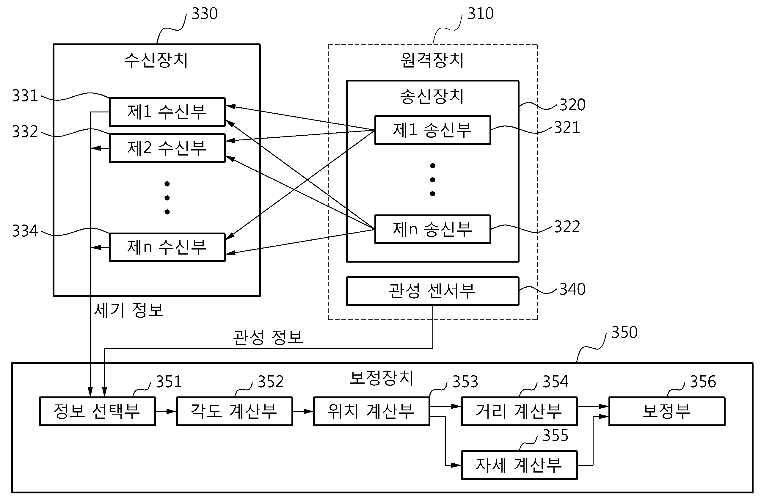
도 3은 3차원 위치/방향 추정 시스템에서 보정 장치의 구성을 도시한 도면,
도 4는 관성정보를 이용하여 송신부에서 각 수신부들로 향하는 벡터 사이의 각도를 측정하는 예를 도시한 도면,
도 5는 보정을 위해 원격장치의 위치를 추정하는 예를 도시한 도면,
도 6은 계산된 송신부의 위치에서 수신부의 지향방향에 위치하는 가상의 송신부 위치의 세기를 계산하는 예를 도시한 도면,
도 7은 거리별 이론적인 신호감쇄특성 모델과 측정된 신호감쇄특성 모델의 예를 도시한 도면 및,
도 8은 수신부 별 성능편차에 의한 신호감쇄특성 차이를 보정하는 방법의 예를 도시한 흐름도이다. FIG. 1 is a diagram showing a transmission-directing characteristic of infrared rays in which a receiving intensity of an infrared ray varies according to a transmission directing direction of an infrared ray signal,
2 is a diagram showing the transmission directivity and the reception directivity of an infrared signal,
3 is a diagram showing a configuration of a correction device in a three-dimensional position /
4 is a diagram illustrating an example of measuring an angle between vectors directed from the transmitter to the receivers using inertia information,
5 shows an example of estimating the position of a remote device for correction,
6 is a diagram illustrating an example of calculating the intensity of a virtual transmitter position located in the direction of the calculated reception position of the transmitter,
FIG. 7 is a diagram showing an example of a theoretical signal attenuation characteristic model and a measured signal attenuation characteristic model by distance,
8 is a flowchart showing an example of a method of correcting a difference in signal attenuation characteristics due to a performance deviation of each receiving unit.
이하, 본 발명의 실시 예를 첨부된 도면을 참조하여 상세하게 설명한다. DETAILED DESCRIPTION OF THE PREFERRED EMBODIMENTS Hereinafter, embodiments of the present invention will be described in detail with reference to the accompanying drawings.
신호는 감쇄 특성을 가지고 있어 송신부와 수신부 사이의 거리와 송신부와 수신부 각각의 지향 방향에 따라 그 측정 세기가 달라진다. 이렇게 감쇄특성을 가지는 신호는 여러가지가 있으나 이하의 설명에서는 적외선 신호를 기준으로 설명하고자 한다.The signal has an attenuation characteristic, and the measured intensity varies depending on the distance between the transmitter and the receiver and the direction of the transmitter and receiver. There are a variety of signals having such attenuation characteristics, but the following description will be based on an infrared signal.
도 1은 적외선 신호의 송신 지향 방향에 따라 적외선의 수신 세기가 달라지는 적외선의 송신 지향 특성을 도시한 도면이다.FIG. 1 is a view showing a transmission directivity characteristic of an infrared ray in which a receiving intensity of an infrared ray varies according to a transmission directing direction of an infrared ray signal.
도 1을 참조하면, 적외선은 정해진 거리에서 적외선 신호의 지향 방향인 송신부의 방향각에 따라 적외선의 수신 세기가 달라지는 특성을 가진다. 도 1에서 Z축은 송신 적외선의 세기를 나타내고, X축과 Y축은 수신부에서 송신부를 측정하는 측정 각도를 나타낸다. 이하 설명에서 송신 지향 특성은 적외선 신호를 송신하는 지향 방향에 따라 수신 세기가 달라지는 적외선의 특성이다.Referring to FIG. 1, an infrared ray has a characteristic that an intensity of an infrared ray varies according to a direction angle of a transmitter, which is a direction of an infrared ray signal at a predetermined distance. 1, the Z axis represents the intensity of the transmission infrared rays, and the X axis and the Y axis represent measurement angles at which the transmitter measures the transmitter. In the following description, the transmission direction characteristic is an infrared ray characteristic in which the reception intensity varies depending on the direction in which the infrared signal is transmitted.
도 2는 적외선 신호의 송신 지향 특성 및 수신 지향 특성을 도시한 도면이다.2 is a diagram showing the transmission directivity and the reception directivity of an infrared signal.
도 2를 참조하면, A와 B의 수신 세기를 비교하면 알 수 있듯이 적외선 신호의 수신 세기는 송신 지향 방향각(θ)에 따라 달라진다. 또한, 적외선 신호의 수신 세기는 수신부에서 적외선 신호를 수신하는 방향인 수신 지향 방향각(ψ)에 따라서도 영향을 받는다. 이하 설명에서 수신 지향 특성은 적외선을 수신하는 지향 방향에 따라 수신 세기가 달라지는 적외선의 특성이다. Referring to FIG. 2, as can be seen by comparing the reception intensities of A and B, the reception intensities of the infrared signals depend on the transmission direction angle?. Further, the reception intensity of the infrared signal is also influenced by the reception direction angle (?), Which is the direction in which the infrared signal is received by the receiver. In the following description, the reception directivity is a characteristic of infrared rays whose receiving intensity changes according to the directivity direction for receiving infrared rays.
송신부와 수신부 사이의 거리에 따라 측정되는 신호의 세기는 아래 <수학식 1>과 같은 특성을 가진다.The intensity of the signal measured according to the distance between the transmitter and the receiver has the following Equation (1).

여기서, I는 측정되는 신호의 세기이고, r은 송신부와 수신부 사이의 거리이다.Where I is the intensity of the signal being measured and r is the distance between the transmitter and receiver.
송신부의 지향 방향에 따라 측정되는 신호의 세기는 아래 <수학식 2>과 같은 특성을 가진다.The intensity of the signal measured according to the direction of the transmission unit has the following Equation (2).

여기서, I는 측정되는 신호의 세기이고, κ는 송신부의 감쇄 특성을 나타내는 변수이고, θ는 송신부가 지향하는 방향각이다.Where I is the intensity of the signal being measured, κ is a variable indicating the attenuation characteristics of the transmitter, and θ is the direction angle that the transmitter is aiming at.
수신부의 지향 방향에 따라 측정되는 신호의 세기는 아래 <수학식 3>과 같은 특성을 가진다.The intensity of the signal measured according to the direction of the receiving unit has the following Equation (3).

여기서, I는 측정되는 신호의 세기이고, λ는 수신부의 감쇄 특성을 나타내는 변수이고, ψ는 수신부가 지향하는 방향각이다.Where I is the intensity of the measured signal, lambda is the variable indicative of the attenuation characteristic of the receiver, and [psi] is the direction angle directed by the receiver.
그러면, 송신부와 수신부 사이의 거리와 송신부의 지향 방향, 수신부의 지향 방향에 따른 특성을 모두 고려하여 측정되는 적외선의 신호 세기는 아래 <수학식 4>와 같이 측정할 수 있다.Then, the signal intensity of the infrared ray, which is measured in consideration of the distance between the transmitter and the receiver, the direction of the transmitter, and the direction of the receiver, can be measured as shown in Equation (4) below.
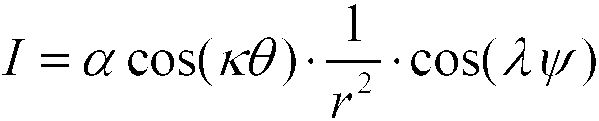
여기서, I는 측정되는 신호의 세기이고, r은 송신부와 수신부 사이의 거리이고, α는 송신부와 수신부의 특성을 고려한 스케일 팩터이고, κ는 송신부의 감쇄 특성을 나타내는 변수이고, θ는 송신부가 지향하는 방향각이고, λ는 수신부의 감쇄 특성을 나타내는 변수이고, ψ는 수신부가 지향하는 방향각이다.Where I is the intensity of the signal being measured, r is the distance between the transmitter and the receiver, alpha is a scale factor taking into account the characteristics of the transmitter and receiver, k is a variable indicative of the attenuation characteristics of the transmitter, Is a directional angle at which the receiving unit is oriented, and [lambda] is a variable representing the attenuation characteristic of the receiving unit.
도 3은 3차원 위치/방향 추정 시스템에서 보정 장치의 구성을 도시한 도면이다.3 is a diagram showing a configuration of a correction apparatus in a three-dimensional position / direction estimation system.
도 3을 참조하면, 3차원 위치/방향 추정 시스템은 원격장치(310), 송신장치(320), 수신장치(330) 및 보정장치(350)를 포함할 수 있다. 또한, 3차원 위치/방향 추정 시스템은 수신장치(330)와 원격장치(310)로부터 수신하는 정보들을 이용해서 3차원 위치/방향을 추정하는 추정장치(미도시)를 더 포함할 수 있다.Referring to FIG. 3, a three-dimensional location / direction estimation system may include a
원격장치(310)는 위치와 방향을 추정하는 목표 장치로서 관성정보들을 측정하는 관성 센서부(340)와 송신장치(320)를 포함한다. 여기서, 관성 센서부(340)는 가속도 센서, 지자가 센서 또는 자이로 센서 중 적어도 하나를 포함해서 구성될 수 있으며, 관성정보는 3축의 운동 가속도, 3축의 중력 가속도 및 3축의 각속도 중에도 적어도 하나를 포함하는 정보이다. 도 3의 예에서 원격장치(310)는 송신장치(320)를 포함하고 있지만, 송신장치(320) 대신에 수신장치(330)를 포함할 수 도 있다. 즉, 원격장치(310)는 송신장치(320) 혹은 수신장치(330)를 포함할 수 있다.The
송신장치(320)는 1개 이상의 송신부(321, 322)를 포함할 수 있다.Transmitting
송신부(321, 322)는 신호를 송신한다. 이때, 송신부(321, 322)가 2개 이상인 경우, 송신부(321, 322)들 각각의 지향 방향이 서로 다르고 지향 방향들 간의 각도가 기설정된다. 그리고, 송신부(321, 322)에서 송신하는 신호는 광신호일 수도 있고, 전자기장(Electromagnetic Field)일 수도 있다. 이때, 광신호의 대표적인 예로 적외선(InfraRed)이 사용될 수 있다. 송신부(321, 322)에서 송신하는 신호가 광신호인 경우 송신부(321, 322)는 광조사부가 될 수 있고, 송신부(321, 322)에서 송신하는 신호가 전자기장인 경우 송신부(321, 322)는 전자기장 송신부가 될 수 있다. 이하의 설명에서는 송신부(321, 322)에서 광신호를 송신할 때를 기준으로 설명한다.The transmitting
1개 이상의 송신부(321, 322) 중에서 하는 전자 기기를 컨트롤하는 리모컨의 적외선 발신부로 동작할 수도 있다.It may be operated as an infrared ray transmitter of a remote controller for controlling an electronic device among the one or
수신장치(330)는 1개 이상의 수신부(331, 332, 334)를 포함할 수 있다.The receiving
수신부(331, 332, 334)는 송신부(321, 322)에서 송신하는 신호를 수신해서 수신한 신호의 세기를 측정한다. 이때, 수신부(331, 332, 334)가 2개 이상인 경우, 수신부(331, 332, 334)들 각각의 위치와 지향방향은 기설정 될 수 있다. 즉, 수신부(331, 332, 334)의 위치와 지향 방향은 각각 다르게 설정될 수 있다.The receiving
수신부(331, 332, 334)에서 수신하는 신호는 광신호일 수도 있고, 전자기장일 수도 있다. 수신부(331, 332, 334)에서 수신하는 신호가 광신호인 경우 수신부(331, 332, 334)는 수광부가 될 수 있고, 수신부(331, 332, 334)에서 송신하는 신호가 전자기장인 경우 수신부(331, 332, 334)는 자력계(magnetometer)가 될 수 있다. 이하의 설명에서는 수신부(331, 332, 334)에서 광신호를 수신할 때를 기준으로 설명한다.The signals received by the receiving
수신부(331, 332, 334)는 송신부(321, 322)가 2개 이상인 경우, 신호들이 수신되는 기설정된 순서를 통해 송신부(321, 322)를 구분할 수 있다. 이때, 송신부(321, 322)가 2개 이상인 경우, 수신부(331, 332, 334)는 송신장치(320)로부터 신호를 수신하기에 앞서 동기 신호를 수신하면 송신장치(320)와 동기화 한다.The receiving
수신부(331, 332, 334)는 송신부(321, 322)가 2개 이상인 경우, 서로 다른 주파수의 신호들을 필터(미도시)를 이용해서 분리해서 기설정된 주파수에 대응하는 송신부(321, 322)들을 구분한다.When there are two or
보정장치(350)는 기설정된 기간 동안 관성센서부(340)로부터 관성정보들을 수신하고, 수신부(331, 332, 334)들로부터 세기정보(Intensity)들을 수신해서 수신부(331, 332, 334)들과 송신부(321, 322) 간의 거리들을 계산하고, 수신부(331, 332, 334)들과 송신부(321, 322) 간의 거리들을 이용해서 수신부(331, 332, 334)들 각각에서의 신호감쇄특성을 보정한다.The
보정장치(350)는 정보 선택부(351), 각도 계산부(352), 위치 계산부(353), 거리 계산부(354), 자세 계산부(355) 및 보정부(356)를 포함할 수 있다.The
정보 선택부(351)는 기설정된 기간 동안 수신부(331, 332, 334)들 각각에서 측정한 신호의 세기정보들을 수신하고, 같은 기간 동안 원격장치(350)로부터 관성정보를 수신하고, 수신부(331, 332, 334)들 별로 가장 강한 세기정보를 선택하고, 가장 강한 세기정보를 수신했을 때의 관성정보를 확인한다.The
기설정된 기간 동안 수신부(331, 332, 334)들 각각에서 수신되는 신호는 기설정된 기간 동안 송신부(321)가 고정점을 기준을 수평 또는 수직으로 회전되면서 송신한 신호이다. 이때, 송신부(321)가 한점에서 회전하기 어렵다고 하면 조금 더 간단한 방법으로 사람의 움직임을 이용해 보정을 할 수도 있다. The signal received by each of the receiving
일반적으로 사람의 움직임은 팔꿈치나 어깨 등을 원점으로 회전운동을 하게 된다. 사람의 팔꿈치 및 어깨 등의 관절을 중심으로 발광부가 회전중심에서 바깥쪽으로 향하도록 고정시키고 움직일 경우 회전운동을 하게 되고, 사람의 움직임이 팔 혹은 상박이 길이가 일반적으로 편차가 크지 않기 때문에(편차가 크더라도 수신부와 송신부 간 떨어진 길이에 비해 편차가 작기 때문에) 이 길이와 송신부의 자세값을 이용하여 송신부의 위치와 회전중심을 알 수 있어 같은 방식으로 거리별 신호감쇄특성을 보정할 수 있다. Generally, the movement of a person is to rotate around the elbow or shoulder. When the light emitting part is fixed so as to move outward from the rotation center around the joints of the elbows and shoulders of the person, the rotation movement is performed. Since the movement of the person is not large in the deviation of the arm or the upper part in general, The position and center of rotation of the transmitter can be known by using the length and the posture value of the transmitter, so that the signal attenuation characteristics of each distance can be corrected in the same manner.
본 발명의 보정장치(350)를 설명함에 있어서 송신부가 하나인 경우를 그 예로 설명하고 있으나, 송신부는 2개 이상일 수 있다.In describing the
각도 계산부(352)는 수신부(331, 332, 334)들 별로 확인한 관성정보를 이용해서 송신부(321)와 수신부(331, 332, 334)들 간의 벡터들 사이의 각도들을 아래 도 4와 같이 계산할 수 있다.The
도 4는 관성정보를 이용하여 송신부에서 각 수신부들로 향하는 벡터 사이의 각도를 측정하는 예를 도시한 도면이다.4 is a diagram showing an example of measuring an angle between vectors directed from the transmitter to the respective receivers using inertia information.
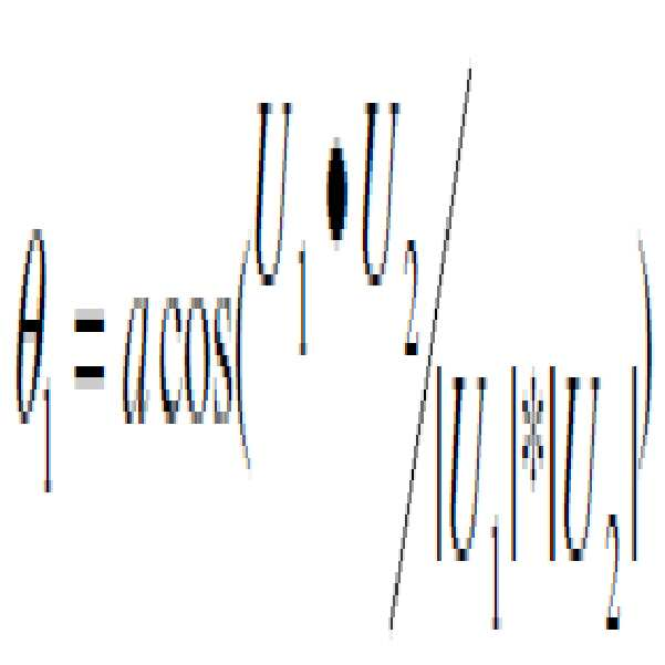
도 4를 참조하면, 송신부(321)을 포함하는 원격장치(310)가 E에서 회전 시 수광부S1(331), 수광부S2(332) 에 측정되는 세기정보가 가장 크거나 혹은 세기정보가 좌우 대칭이 되는 지점의 신호 혹은 세기정보가 0이 되는 양 구간의 중앙점 중에서 적어도 하나를 만족하는 경우에 원격장치(310)의 송신부(321)는 각 수광부(331, 332)를 정면으로 향하게 될 때이고, 이 벡터를 ES1, ES2 라고 한다. 이때 관성센서부(340)에 의해 측정 된 기준 자세에 의해 결정되는 방향 벡터를 수광부(331, 332) 별로 각각 U1, U2 라고 하면, 벡터 U1 과 U2 사이의 각 θ는 θ1 과 같게 되고 이를 구하면 아래 <수학식 5> 에 의해 결정된다.Referring to FIG. 4, when the
위치 계산부(353)는 송신부(321)와 수신부(331, 332, 334)들 간의 벡터들 사이의 각도들을 이용해서 삼각측량 기법으로 원격장치(350)의 3차원 위치를 같이 계산한다.The
도 5는 보정을 위해 원격장치의 위치를 추정하는 예를 도시한 도면이다.5 is a diagram showing an example of estimating the position of a remote device for correction.
도 5를 참조하면, 위치 계산부(353)는 수신부(331, 332, 334)들 3지점 (S1, S2, S3) 의 위치를 알고 각 수신부(S1, S2, S3) 에서 송신부(321)를 포함하는 원격장치(310)가 있는 공간상의 한 지점(E)을 잇는 벡터를 ES1, ES2, ES3 라고 했을 때 각 벡터 사이의 각도 θ1, θ2, θ3 값을 알면 삼각측량에 의해 원격장치(310)가 있는 지점(E) 의 위치를 계산할 수 있다. 5, the
거리 계산부(354)는 위치 계산부(353)에서 계산한 송신부(321)를 포함하는 원격장치(350)의 위치와 미리 알고 있는 수신부(331, 332, 334)들 각각의 위치를 이용해서 수신부(331, 332, 334)들과 송신부(321) 간의 거리들을 계산한다.The
자세 계산부(355)는 수신부(331, 332, 334)들 별로 가장 강한 세기정보를 수신했을 때의 관성정보를 이용해서 수신부(331, 332, 334)들 별로 가장 강한 세기정보를 수신 때의 원격장치(350)의 자세를 계산한다.The
도 6은 계산된 송신부의 위치에서 수신부의 지향방향에 위치하는 가상의 송신부 위치의 세기를 계산하는 예를 도시한 도면이다.FIG. 6 is a diagram illustrating an example of calculating the intensity of a virtual transmitter position located in a direction of a receiver in a calculated position of the transmitter.
도 6을 참조하면, E1에서 발광된 신호를 S1이 측정한 세기정보를 I1 이라 하면, 지향방향의 가상의 선상에 있는 E1’에서 발광된 신호를 측정한 세기정보를 I1’ 다음과 같이 I1' = I1*cos(α1) 와 같이 구할 수 있다. 여기서 α1 은 S1과 E1 의 위치에 의해서 구할 수 있고 S1과 E1’의 거리 d1 도 수신부와 송신부의 위치에 의해 구할 수 있게 된다.Referring to FIG. 6, if intensity information obtained by measuring the signal S1 emitted from E1 is denoted by I1, the intensity information obtained by measuring the signal emitted from E1 'on the imaginary line of the direction is denoted as I1' = I1 * cos (? 1). Here, α1 can be obtained by the positions of S1 and E1, and the distance d1 between S1 and E1 'can be obtained by the positions of the receiver and the transmitter.
보정부(356)는 수신부(331, 332, 334)들 각각의 가장 강한 세기정보와 수신부(331, 332, 334)들과 송신부(321) 간의 거리들을 2회 이상 서로 다른 위치에서 측정하고, 수신부(331, 332, 334)들 각각의 가장 강한 세기정보들과 수신부(331, 332, 334)들과 송신부(321) 간의 거리들을 이용해서 수신부(331, 332, 334)들 각각에서의 신호감쇄특성을 아래 도 7과 같이 보정한다.The
도 7은 거리별 이론적인 신호감쇄특성 모델과 측정된 신호감쇄특성 모델의 예를 도시한 도면이다.7 is a diagram showing an example of the theoretical signal attenuation characteristic model and the measured signal attenuation characteristic model by distance.
도 7을 참조하면, 이론적으로 거리별 감쇄 특성 모델은 I=a(1/R2)+b 와 같이 나타낼 수 있고 이를 풀어보면 세기정보(Intensity) I는 1/R2에 비례하고, 스케일 펙터(Scale Factor) a에 비례하고 오프셋(Offset) b가 더해진다. 여기서 1/R2은 빛의 물리적 특성으로 실제 측정시에도 선형적으로 나타나므로 보정을 해 줄 필요가 없다. 하지만 나머지 파라미터인 스칼라 펙터와 오프셋은 수신부 간의 성능 편차, 장시간 사용에 따른 송신부의 효율 저하, 주변 환경의 영향 등의 요인 들로 인하여 각 수광부 별로 다르게 나타나므로 파라미터 들을 수정함으로써 거리별 감쇄 특성의 측정 모델을 이론적 모델로 보정해주어야 한다. Referring to FIG. 7, theoretically, the attenuation characteristic model for distance can be expressed as I = a (1 / R 2 ) + b. Intensity I is proportional to 1 /
따라서, 보정부(356)는 거리별 감쇄 특성 모델이 1차식으로 나타낼 수 있는 함수 이기 때문에, 수신부가 지향하는 선상의 2군데 이상에서 송신부가 떨어진 거리값과 그에 해당하는 세기정보를 측정해서 스칼라 펙터와 오프셋를 수정해서 보정한다.Therefore, the
한편, 보정부(356)는 수신부(331, 332, 334)들 각각의 신호감쇄특성을 보정할 때, 원격장치(350)의 자세를 이용해서 각도에 따라 달라지는 신호감쇄특성을 고려해서 보정할 수 있다.Meanwhile, when the signal attenuation characteristic of each of the
이하, 상기와 같이 구성된 본 발명에 따른 3차원 위치/방향 추정 시스템의 보정장치에서 신호감쇄특성 차이를 보정하는 방법을 아래에서 도면을 참조하여 설명한다.Hereinafter, a method of correcting the difference in signal attenuation characteristics in the correction apparatus of the three-dimensional position / direction estimation system according to the present invention will be described with reference to the drawings.
도 8은 수신부 별 성능편차에 의한 신호감쇄특성 차이를 보정하는 방법의 예를 도시한 흐름도이다. 8 is a flowchart showing an example of a method of correcting a difference in signal attenuation characteristics due to a performance deviation of each receiving unit.
도 8을 참조하면, 보정장치는 810단계에서 기설정된 기간 동안 수신부들 각각에서 측정한 신호의 세기정보들을 수신하고, 같은 기간 동안 원격장치로부터 관성정보를 수신한다.Referring to FIG. 8, in
그리고, 보정장치는 812단계에서 수신부들 별로 가장 강한 세기정보를 선택한다.In
그리고, 보정장치는 814단계에서 가장 강한 세기정보를 수신했을 때의 관성정보를 확인한다.Then, the correction device confirms the inertia information when the strongest intensity information is received in
그리고, 보정장치는 816단계에서 수신부들 별로 확인한 관성정보를 이용해서 송신부와 수신부들 간의 벡터들 사이의 각도들을 계산한다.In
그리고, 보정장치는 818단계에서 벡터들 사이의 각도들을 이용해서 삼각측량 기법으로 원격장치의 3차원 위치를 계산한다.Then, in
그리고, 보정장치는 820단계에서 수신부들과 송신부 간의 거리들을 계산한다.In
그리고, 보정장치는 822단계에서 수신부들 각각의 가장 강한 세기정보와 수신부들과 송신부 간의 거리들의 계산이 기설정된 횟수만큼 수행되었는지 확인한다.In
822단계의 확인결과 세기정보와 거리 계산이 기설정된 횟수만큼 수행되지 않았으면, 보정장치는 810단계로 돌아가서 810단계에서 820단계를 기설정된 반복한다. 이때, 원격장치의 위치는 이전과 다른 위치에서 수행되는 것이 바람직하다.If it is determined in
822단계의 확인결과 세기정보와 거리 계산이 기설정된 횟수만큼 수행되었으면, 보정장치는 824단계에서 수신부들 각각의 가장 강한 세기정보와 수신부들과 송신부 간의 거리들을 기설정한 횟수 서로 다른 위치에서 측정한 정보를 이용해서 수신부들 각각의 신호감쇄특성을 보정한다. If it is determined in
이상과 같이 본 발명은 비록 한정된 실시예와 도면에 의해 설명되었으나, 본 발명은 상기의 실시예에 한정되는 것은 아니며, 본 발명이 속하는 분야에서 통상의 지식을 가진 자라면 이러한 기재로부터 다양한 수정 및 변형이 가능하다.While the invention has been shown and described with reference to certain preferred embodiments thereof, it will be understood by those of ordinary skill in the art that various changes in form and details may be made therein without departing from the spirit and scope of the invention as defined by the appended claims. This is possible.
그러므로, 본 발명의 범위는 설명된 실시예에 국한되어 정해져서는 아니 되며, 후술하는 특허청구범위뿐 아니라 이 특허청구범위와 균등한 것들에 의해 정해져야 한다.Therefore, the scope of the present invention should not be limited to the described embodiments, but should be determined by the equivalents of the claims, as well as the claims.
Claims (22)
상기 수신부들 별로 확인한 관성정보를 이용해서 상기 방향성을 가진 신호를 송신한 송신부와 상기 수신부들 간의 벡터들 사이의 각도들을 계산하는 각도 계산부; 및
상기 벡터들 사이의 각도들을 이용해서 삼각측량 기법으로 상기 원격장치의 3차원 위치를 계산하는 위치 계산부를 포함하는
3차원 위치/방향 추정 시스템에서 신호감쇄특성을 보정하는 보정장치.
Receiving intensity information of a measured signal, which is a result of receiving a signal having a directional intensity that varies according to a direction in each of the receiving units for a predetermined period, receiving inertia information from the remote device during the same period, An information selection unit for selecting the strongest intensity information for each of the plurality of intensity information and confirming the inertia information when the strongest intensity information is received;
An angle calculator for calculating angles between vectors between the transmitter and the receiver that transmit the signal having the directionality using the inertia information identified for each of the receivers; And
And a position calculator for calculating the three-dimensional position of the remote device with a triangulation technique using angles between the vectors
A correction device for correcting signal attenuation characteristics in a three-dimensional position / direction estimation system.
상기 기설정된 기간 동안 상기 수신부들 각각에서 수신되는 신호는,
상기 기설정된 기간 동안 상기 송신부가 고정점을 기준을 수평 또는 수직으로 회전되면서 송신한 신호인
3차원 위치/방향 추정 시스템에서 신호감쇄특성을 보정하는 보정장치.
The method according to claim 1,
Wherein the signal received at each of the receiving units during the predetermined period comprises:
The transmitter transmits a signal transmitted while the reference point is rotated horizontally or vertically during the preset period
A correction device for correcting signal attenuation characteristics in a three-dimensional position / direction estimation system.
상기 수신부들과 상기 송신부 간의 거리들을 계산하는 거리 계산부; 및
상기 수신부들 각각의 가장 강한 세기정보와 상기 수신부들과 상기 송신부 간의 거리들을 이용해서 상기 수신부들 각각에서의 신호감쇄특성을 보정하는 보정부를 더 포함하는
3차원 위치/방향 추정 시스템에서 신호감쇄특성을 보정하는 보정장치.
The method according to claim 1,
A distance calculation unit for calculating distances between the reception units and the transmission unit; And
And a correction unit for correcting signal strength characteristics of each of the reception units using the strongest intensity information of each of the reception units and distances between the reception units and the transmission unit
A correction device for correcting signal attenuation characteristics in a three-dimensional position / direction estimation system.
상기 보정부는,
상기 수신부들 각각의 가장 강한 세기정보들과 상기 수신부들과 상기 송신부 간의 거리들을 2회 이상 서로 다른 위치에서 측정한 정보를 이용해서 상기 수신부들 각각의 신호감쇄특성을 보정하는
3차원 위치/방향 추정 시스템에서 신호감쇄특성을 보정하는 보정장치.
The method of claim 3,
Wherein,
And corrects the signal attenuation characteristics of each of the reception units using information obtained by measuring the strongest intensity information of each of the reception units and the distances between the reception units and the transmission unit at two or more different positions
A correction device for correcting signal attenuation characteristics in a three-dimensional position / direction estimation system.
상기 수신부들 별로 상기 가장 강한 세기정보를 수신했을 때의 관성정보를 이용해서 상기 수신부들 별로 상기 가장 강한 세기정보를 수신 때의 상기 원격장치의 자세를 계산하는 자세 계산부를 더 포함하고,
상기 보정부는,
상기 수신부들 각각의 신호감쇄특성을 보정할 때, 상기 원격장치의 자세를 이용해서 각도에 따라 달라지는 신호감쇄특성을 고려하는
3차원 위치/방향 추정 시스템에서 신호감쇄특성을 보정하는 보정장치.
The method of claim 3,
Further comprising an attitude calculation unit for calculating the attitude of the remote apparatus when receiving the strongest intensity information for each of the receivers by using the inertia information when the strongest intensity information is received for each of the receivers,
Wherein,
When the signal attenuation characteristic of each of the receiving units is corrected, a signal attenuation characteristic depending on the angle is considered using the attitude of the remote apparatus
A correction device for correcting signal attenuation characteristics in a three-dimensional position / direction estimation system.
상기 수신부들은,
적어도 3개 이상인
3차원 위치/방향 추정 시스템에서 신호감쇄특성을 보정하는 보정장치.
The method according to claim 1,
The receiving units,
At least three
A correction device for correcting signal attenuation characteristics in a three-dimensional position / direction estimation system.
상기 송신부는,
서로 다른 방향을 지향하는 2개 이상의 송신부로 구성되는
3차원 위치/방향 추정 시스템에서 신호감쇄특성을 보정하는 보정장치.
The method according to claim 1,
The transmitter may further comprise:
Consisting of two or more transmitters oriented in different directions
A correction device for correcting signal attenuation characteristics in a three-dimensional position / direction estimation system.
상기 원격장치는,
상기 관성정보들을 측정하는 관성 센서부를 포함하고,
상기 송신부 혹은 상기 수신부들 중 하나를 포함하는
3차원 위치/방향 추정 시스템에서 신호감쇄특성을 보정하는 보정장치.
The method according to claim 1,
The remote device comprising:
And an inertial sensor unit for measuring the inertia information,
Wherein the transmitter includes one of the transmitter and the receiver,
A correction device for correcting signal attenuation characteristics in a three-dimensional position / direction estimation system.
상기 세기 정보들은,
기설정된 파장으로 조사된 광신호의 세기값인
3차원 위치/방향 추정 시스템에서 신호감쇄특성을 보정하는 보정장치.
The method according to claim 1,
The intensity information,
Which is the intensity value of the optical signal irradiated to the predetermined wavelength
A correction device for correcting signal attenuation characteristics in a three-dimensional position / direction estimation system.
상기 관성정보들은,
관성 센서를 통해 측정되는 3축의 운동 가속도, 3축의 중력 가속도 및 3축의 각속도 중에도 적어도 하나를 포함하는
3차원 위치/방향 추정 시스템에서 신호감쇄특성을 보정하는 보정장치.
The method according to claim 1,
The inertia information,
The acceleration of three axes measured through the inertia sensor, the acceleration of gravity of three axes and the angular velocity of three axes
A correction device for correcting signal attenuation characteristics in a three-dimensional position / direction estimation system.
상기 수신부들 별로 가장 강한 세기정보를 선택하는 단계;
상기 가장 강한 세기정보를 수신했을 때의 관성정보를 확인하는 단계;
상기 수신부들 별로 확인한 관성정보를 이용해서 상기 방향성을 가진 신호를 송신한 송신부와 상기 수신부들 간의 벡터들 사이의 각도들을 계산하는 단계; 및
상기 벡터들 사이의 각도들을 이용해서 삼각측량 기법으로 상기 원격장치의 3차원 위치를 계산하는 단계를 포함하는
3차원 위치/방향 추정 시스템의 보정장치에서 신호감쇄특성을 보정하는 방법.
Receiving intensity information of a measured signal, which is a result of receiving a signal having a directional intensity that varies according to a direction, in each of the receiving units during a predetermined period, and receiving inertia information from the remote device during the same period;
Selecting the strongest intensity information for each of the receiving units;
Confirming inertia information when the strongest intensity information is received;
Calculating angles between vectors between the transmitting unit and the receiving unit that transmit the directional signal using the inertia information identified for each of the receiving units; And
Calculating the three-dimensional position of the remote device with a triangulation technique using angles between the vectors
A method for correcting signal attenuation characteristics in a correction device of a three-dimensional position / direction estimation system.
상기 기설정된 기간 동안 상기 수신부들 각각에서 수신되는 신호는,
상기 기설정된 기간 동안 상기 송신부가 고정점을 기준을 수평 또는 수직으로 회전되면서 송신한 신호인
3차원 위치/방향 추정 시스템의 보정장치에서 신호감쇄특성을 보정하는 방법.
12. The method of claim 11,
Wherein the signal received at each of the receiving units during the predetermined period comprises:
The transmitter transmits a signal transmitted while the reference point is rotated horizontally or vertically during the preset period
A method for correcting signal attenuation characteristics in a correction device of a three-dimensional position / direction estimation system.
상기 상기 원격장치의 3차원 위치를 계산하는 단계 이후에,
상기 수신부들과 상기 송신부 간의 거리들을 계산하는 단계; 및
상기 수신부들 각각의 가장 강한 세기정보와 상기 수신부들과 상기 송신부 간의 거리들을 이용해서 상기 수신부들 각각에서의 신호감쇄특성을 보정하는 단계를 더 포함하는
3차원 위치/방향 추정 시스템의 보정장치에서 신호감쇄특성을 보정하는 방법.
12. The method of claim 11,
After calculating the three-dimensional position of the remote device,
Calculating distances between the receiving units and the transmitting unit; And
And correcting the signal attenuation characteristic in each of the reception units using the strongest intensity information of each of the reception units and the distances between the reception units and the transmission unit
A method for correcting signal attenuation characteristics in a correction device of a three-dimensional position / direction estimation system.
상기 보정하는 단계는,
상기 수신부들 각각의 가장 강한 세기정보와 상기 수신부들과 상기 송신부 간의 거리들을 2회 이상 서로 다른 위치에서 측정한 정보를 이용해서 상기 수신부들 각각의 신호감쇄특성을 보정하는
3차원 위치/방향 추정 시스템의 보정장치에서 신호감쇄특성을 보정하는 방법.
14. The method of claim 13,
Wherein the correcting comprises:
And corrects the signal attenuation characteristic of each of the reception units using information obtained by measuring the strongest intensity information of each of the reception units and the distances between the reception units and the transmission unit at two or more different positions
A method for correcting signal attenuation characteristics in a correction device of a three-dimensional position / direction estimation system.
상기 수신부들 별로 상기 가장 강한 세기정보를 수신했을 때의 관성정보를 이용해서 상기 수신부들 별로 상기 가장 강한 세기정보를 수신 때의 상기 원격장치의 자세를 계산하는 단계를 더 포함하고,
상기 보정하는 단계는,
상기 수신부들 각각의 신호감쇄특성을 보정할 때, 상기 원격장치의 자세를 이용해서 각도에 따라 달라지는 신호감쇄특성을 고려하는
3차원 위치/방향 추정 시스템의 보정장치에서 신호감쇄특성을 보정하는 방법.
14. The method of claim 13,
Further comprising the step of calculating an attitude of the remote apparatus when receiving the strongest intensity information for each of the receiving units using inertia information when the strongest strength information is received for each of the receiving units,
Wherein the correcting comprises:
When the signal attenuation characteristic of each of the receiving units is corrected, a signal attenuation characteristic depending on the angle is considered using the attitude of the remote apparatus
A method for correcting signal attenuation characteristics in a correction device of a three-dimensional position / direction estimation system.
방향에 따라 수신 세기가 달라지는 방향성을 가진 상기 신호를 수신하고 상기 신호의 세기를 측정하는 적어도 3개의 수신부들을 포함하고 세기 정보들을 출력하는 수신장치;
관성정보들을 측정하는 관성 센서부를 포함하고, 상기 송신장치 혹은 상기 수신장치 중 하나를 포함하는 원격장치; 및
기설정된 기간 동안 상기 관성정보들과 상기 세기정보들을 수신해서 상기 수신부들과 상기 송신부 간의 거리들을 계산하고, 상기 수신부들과 상기 송신부 간의 거리들을 이용해서 상기 수신부들 각각에서의 신호감쇄특성을 보정하는 보정장치를 포함하고,
상기 보정장치는,
상기 기설정된 기간 동안 상기 수신부들 각각에서 측정한 신호의 세기정보들을 수신하고, 같은 기간 동안 상기 원격장치로부터 관성정보를 수신하고, 상기 수신부들 별로 가장 강한 세기정보를 선택하고, 상기 가장 강한 세기정보를 수신했을 때의 관성정보를 확인하는 정보 선택부;
상기 수신부들 별로 확인한 관성정보를 이용해서 상기 송신부와 상기 수신부들 간의 벡터들 사이의 각도들을 계산하는 각도 계산부;
상기 벡터들 사이의 각도들을 이용해서 삼각측량 기법으로 상기 원격장치의 3차원 위치를 계산하는 위치 계산부;
상기 수신부들과 상기 송신부 간의 거리들을 계산하는 거리 계산부; 및
상기 수신부들 각각의 가장 강한 세기정보와 상기 수신부들과 상기 송신부 간의 거리들을 이용해서 상기 수신부들 각각의 신호감쇄특성을 보정하는 보정부를 포함하는
3차원 위치 및 방향을 추정하는 시스템.
A transmitter including at least one transmitter for transmitting a directional signal for intensity measurement;
A reception device for receiving the signal having a directional intensity that varies according to a direction and measuring intensity of the signal and outputting intensity information;
A remote device comprising an inertial sensor part for measuring inertia information, said remote device comprising one of said transmitting device or said receiving device; And
Calculating the distances between the reception units and the transmission unit by receiving the inertia information and the intensity information for a predetermined period of time and correcting signal attenuation characteristics in each of the reception units using distances between the reception units and the transmission unit A correction device,
Wherein the correcting device comprises:
Receiving intensity information of signals measured at each of the receivers during the predetermined period, receiving inertia information from the remote device during the same period, selecting the strongest intensity information for each receiver, An information selecting unit for confirming the inertia information when receiving the inertia information;
An angle calculation unit for calculating angles between vectors between the transmitter and the receiver using the inertia information identified for each of the receiver units;
A position calculation unit for calculating a three-dimensional position of the remote device by using a triangulation technique using angles between the vectors;
A distance calculation unit for calculating distances between the reception units and the transmission unit; And
And a correction unit for correcting signal strength characteristics of each of the reception units using the strongest intensity information of each of the reception units and distances between the reception units and the transmission unit
A system for estimating three-dimensional position and orientation.
상기 기설정된 기간 동안 상기 수신부들 각각에서 수신되는 신호는,
상기 기설정된 기간 동안 상기 송신부가 고정점을 기준을 수평 또는 수직으로 회전되면서 송신한 신호인
3차원 위치 및 방향을 추정하는 시스템.
17. The method of claim 16,
Wherein the signal received at each of the receiving units during the predetermined period comprises:
The transmitter transmits a signal transmitted while the reference point is rotated horizontally or vertically during the preset period
A system for estimating three-dimensional position and orientation.
상기 보정부는,
상기 수신부들 각각의 가장 강한 세기정보와 상기 수신부들과 상기 송신부 간의 거리들을 2회 이상 서로 다른 위치에서 측정한 정보를 이용해서 상기 수신부들 각각의 신호감쇄특성을 보정하는
3차원 위치 및 방향을 추정하는 시스템.
17. The method of claim 16,
Wherein,
And corrects the signal attenuation characteristic of each of the reception units using information obtained by measuring the strongest intensity information of each of the reception units and the distances between the reception units and the transmission unit at two or more different positions
A system for estimating three-dimensional position and orientation.
상기 수신부들 별로 상기 가장 강한 세기정보를 수신했을 때의 관성정보를 이용해서 상기 수신부들 별로 상기 가장 강한 세기정보를 수신 때의 상기 원격장치의 자세를 계산하는 자세 계산부를 더 포함하고
상기 보정부는,
상기 수신부들 각각의 신호감쇄특성을 보정할 때, 상기 원격장치의 자세를 이용해서 각도에 따라 달라지는 신호감쇄특성을 고려하는
3차원 위치 및 방향을 추정하는 시스템.
17. The method of claim 16,
And an attitude calculation unit for calculating the attitude of the remote apparatus when receiving the strongest intensity information for each of the receiving units using inertia information when the strongest intensity information is received for each of the receiving units
Wherein,
When the signal attenuation characteristic of each of the receiving units is corrected, a signal attenuation characteristic depending on the angle is considered using the attitude of the remote apparatus
A system for estimating three-dimensional position and orientation.
상기 수신부들은,
적어도 3개 이상인
3차원 위치 및 방향을 추정하는 시스템.
17. The method of claim 16,
The receiving units,
At least three
A system for estimating three-dimensional position and orientation.
상기 송신부는,
서로 다른 방향을 지향하는 2개 이상의 송신부로 구성되는
3차원 위치 및 방향을 추정하는 시스템.17. The method of claim 16,
The transmitter may further comprise:
Consisting of two or more transmitters oriented in different directions
A system for estimating three-dimensional position and orientation.
Priority Applications (2)
| Application Number | Priority Date | Filing Date | Title |
|---|---|---|---|
| KR1020120030477A KR101956173B1 (en) | 2012-03-26 | 2012-03-26 | Apparatus and Method for Calibrating 3D Position/Orientation Tracking System |
| US13/666,518 US9557190B2 (en) | 2012-03-26 | 2012-11-01 | Calibration apparatus and method for 3D position/direction estimation system |
Applications Claiming Priority (1)
| Application Number | Priority Date | Filing Date | Title |
|---|---|---|---|
| KR1020120030477A KR101956173B1 (en) | 2012-03-26 | 2012-03-26 | Apparatus and Method for Calibrating 3D Position/Orientation Tracking System |
Publications (2)
| Publication Number | Publication Date |
|---|---|
| KR20130108771A KR20130108771A (en) | 2013-10-07 |
| KR101956173B1 true KR101956173B1 (en) | 2019-03-08 |
Family
ID=49213030
Family Applications (1)
| Application Number | Title | Priority Date | Filing Date |
|---|---|---|---|
| KR1020120030477A Active KR101956173B1 (en) | 2012-03-26 | 2012-03-26 | Apparatus and Method for Calibrating 3D Position/Orientation Tracking System |
Country Status (2)
| Country | Link |
|---|---|
| US (1) | US9557190B2 (en) |
| KR (1) | KR101956173B1 (en) |
Families Citing this family (5)
| Publication number | Priority date | Publication date | Assignee | Title |
|---|---|---|---|---|
| CN105572883B (en) * | 2014-10-11 | 2018-01-30 | 深圳超多维光电子有限公司 | The correction system of 3 d display device and its bearing calibration |
| US10012733B2 (en) * | 2015-06-07 | 2018-07-03 | Geoffrey Louis Barrows | Localization method and apparatus |
| KR101941604B1 (en) * | 2017-01-20 | 2019-01-24 | 만도헬라일렉트로닉스(주) | Method for estimating position of wearable devices and apparatus using the same |
| CN111051912B (en) * | 2017-08-31 | 2025-02-18 | 株式会社村田制作所 | Position estimation system |
| KR102643525B1 (en) * | 2018-10-30 | 2024-03-06 | 한국전자통신연구원 | Method and apparatus of estimating location of signal source |
Citations (2)
| Publication number | Priority date | Publication date | Assignee | Title |
|---|---|---|---|---|
| US20050077085A1 (en) * | 2003-10-14 | 2005-04-14 | Rudolf Zeller | Tracking positions of personnel, vehicles, and inanimate objects |
| JP2011232335A (en) | 2010-04-26 | 2011-11-17 | Samsung Electronics Co Ltd | System and method for estimating position and direction |
Family Cites Families (20)
| Publication number | Priority date | Publication date | Assignee | Title |
|---|---|---|---|---|
| JPH06103360A (en) | 1992-09-21 | 1994-04-15 | Toshiba Corp | 3D image display system |
| JP5053078B2 (en) | 2004-04-30 | 2012-10-17 | ヒルクレスト・ラボラトリーズ・インコーポレイテッド | Handheld pointing device and method of operating the same |
| JP4805633B2 (en) * | 2005-08-22 | 2011-11-02 | 任天堂株式会社 | Game operation device |
| US20070080940A1 (en) * | 2005-10-07 | 2007-04-12 | Sharp Kabushiki Kaisha | Remote control system, and display device and electronic device using the remote control system |
| KR100813998B1 (en) | 2006-10-17 | 2008-03-14 | (주)펜앤프리 | 3D location tracking method and device |
| US8291346B2 (en) * | 2006-11-07 | 2012-10-16 | Apple Inc. | 3D remote control system employing absolute and relative position detection |
| US20080291160A1 (en) * | 2007-05-09 | 2008-11-27 | Nintendo Co., Ltd. | System and method for recognizing multi-axis gestures based on handheld controller accelerometer outputs |
| EP2215894A2 (en) * | 2007-11-16 | 2010-08-11 | Koninklijke Philips Electronics N.V. | Direction controllable lighting unit with ultrasound |
| KR101400230B1 (en) | 2008-03-11 | 2014-05-28 | 삼성전자주식회사 | Three dimensional pointing input apparatus and method thereof |
| KR100940095B1 (en) | 2008-03-17 | 2010-02-02 | (주)마이크로인피니티 | Pointer movement value calculation device, pointer movement value correction method and posture angle variation correction method, three-dimensional pointing device using the same |
| KR20090106767A (en) * | 2008-04-07 | 2009-10-12 | 엘지전자 주식회사 | Pointing device and method in three-dimensional space |
| KR100908099B1 (en) | 2008-06-03 | 2009-07-16 | 엘지전자 주식회사 | How to execute functions of DVT, 3D pointing device and DVT |
| FR2933212B1 (en) * | 2008-06-27 | 2013-07-05 | Movea Sa | MOVING CAPTURE POINTER RESOLVED BY DATA FUSION |
| EP2297675A4 (en) | 2008-07-01 | 2014-04-09 | Hillcrest Lab Inc | 3d pointer mapping |
| US9399167B2 (en) * | 2008-10-14 | 2016-07-26 | Microsoft Technology Licensing, Llc | Virtual space mapping of a variable activity region |
| US8008613B2 (en) | 2009-05-05 | 2011-08-30 | Apple Inc. | Light sensing device having a color sensor and a clear sensor for infrared rejection |
| KR20110012584A (en) * | 2009-07-31 | 2011-02-09 | 삼성전자주식회사 | Ultrasonic Based 3D Position Estimation Apparatus and Method |
| KR101103058B1 (en) | 2009-08-25 | 2012-01-05 | 김근섭 | Computer system and its driving method |
| KR101080078B1 (en) * | 2009-12-08 | 2011-11-04 | 숭실대학교산학협력단 | Motion Capture System using Integrated Sensor System |
| KR20120028416A (en) * | 2010-09-14 | 2012-03-23 | 삼성전자주식회사 | Integration motion sensing device |
-
2012
- 2012-03-26 KR KR1020120030477A patent/KR101956173B1/en active Active
- 2012-11-01 US US13/666,518 patent/US9557190B2/en active Active
Patent Citations (2)
| Publication number | Priority date | Publication date | Assignee | Title |
|---|---|---|---|---|
| US20050077085A1 (en) * | 2003-10-14 | 2005-04-14 | Rudolf Zeller | Tracking positions of personnel, vehicles, and inanimate objects |
| JP2011232335A (en) | 2010-04-26 | 2011-11-17 | Samsung Electronics Co Ltd | System and method for estimating position and direction |
Also Published As
| Publication number | Publication date |
|---|---|
| US9557190B2 (en) | 2017-01-31 |
| US20130253869A1 (en) | 2013-09-26 |
| KR20130108771A (en) | 2013-10-07 |
Similar Documents
| Publication | Publication Date | Title |
|---|---|---|
| Zhao et al. | Motion measurement using inertial sensors, ultrasonic sensors, and magnetometers with extended kalman filter for data fusion | |
| US8203487B2 (en) | Tightly coupled UWB/IMU pose estimation system and method | |
| US6176837B1 (en) | Motion tracking system | |
| CN102279380B (en) | System and method for estimating position and orientation | |
| KR101815938B1 (en) | Method and apparatus for estimating 3D position and orientation by means of sensor fusion | |
| US11397220B2 (en) | Distortion correction for tracking an object in a magnetic field | |
| KR101920473B1 (en) | Method and apparatus for estimating 3D position and orientation by means of sensor fusion | |
| US20100148977A1 (en) | Localization and detection system applying sensors and method thereof | |
| KR101956173B1 (en) | Apparatus and Method for Calibrating 3D Position/Orientation Tracking System | |
| CN107110953A (en) | Underwater positioning system | |
| WO2016183812A1 (en) | Mixed motion capturing system and method | |
| JP2004212400A (en) | Position and direction estimation system for robots | |
| CN101566528A (en) | Parameter detection system | |
| US20120065926A1 (en) | Integrated motion sensing apparatus | |
| US11150321B2 (en) | System for orientation estimation from radio measurements | |
| KR20170119272A (en) | 3D Motion Input Apparatus for Virtual Reality Device | |
| KR101984504B1 (en) | System and Method for estimating 3D position and orientation accurately | |
| CN115291167B (en) | A human body posture capture and positioning method based on ultrasonic short baseline array | |
| KR101227402B1 (en) | System and method for accuracy comparison of the target detecting sensor | |
| CN121348346A (en) | Fire source positioning method and system based on combination of thermal imaging and laser ranging | |
| US20190162833A1 (en) | Ultrasonic position detection system | |
| CN110388916A (en) | Combined positioning method and its system towards three-dimensional space |
Legal Events
| Date | Code | Title | Description |
|---|---|---|---|
| PA0109 | Patent application |
Patent event code: PA01091R01D Comment text: Patent Application Patent event date: 20120326 |
|
| PG1501 | Laying open of application | ||
| A201 | Request for examination | ||
| PA0201 | Request for examination |
Patent event code: PA02012R01D Patent event date: 20170327 Comment text: Request for Examination of Application Patent event code: PA02011R01I Patent event date: 20120326 Comment text: Patent Application |
|
| E902 | Notification of reason for refusal | ||
| PE0902 | Notice of grounds for rejection |
Comment text: Notification of reason for refusal Patent event date: 20180801 Patent event code: PE09021S01D |
|
| E701 | Decision to grant or registration of patent right | ||
| PE0701 | Decision of registration |
Patent event code: PE07011S01D Comment text: Decision to Grant Registration Patent event date: 20190101 |
|
| GRNT | Written decision to grant | ||
| PR0701 | Registration of establishment |
Comment text: Registration of Establishment Patent event date: 20190304 Patent event code: PR07011E01D |
|
| PR1002 | Payment of registration fee |
Payment date: 20190305 End annual number: 3 Start annual number: 1 |
|
| PG1601 | Publication of registration | ||
| PR1001 | Payment of annual fee |
Payment date: 20220216 Start annual number: 4 End annual number: 4 |
|
| PR1001 | Payment of annual fee |
Payment date: 20230214 Start annual number: 5 End annual number: 5 |
|
| PR1001 | Payment of annual fee |
Payment date: 20240219 Start annual number: 6 End annual number: 6 |