KR101932717B1 - Imaging lens system - Google Patents
Imaging lens system Download PDFInfo
- Publication number
- KR101932717B1 KR101932717B1 KR1020120014402A KR20120014402A KR101932717B1 KR 101932717 B1 KR101932717 B1 KR 101932717B1 KR 1020120014402 A KR1020120014402 A KR 1020120014402A KR 20120014402 A KR20120014402 A KR 20120014402A KR 101932717 B1 KR101932717 B1 KR 101932717B1
- Authority
- KR
- South Korea
- Prior art keywords
- lens
- object side
- lens group
- refractive power
- positive
- Prior art date
- Legal status (The legal status is an assumption and is not a legal conclusion. Google has not performed a legal analysis and makes no representation as to the accuracy of the status listed.)
- Active
Links
Images


Classifications
-
- G—PHYSICS
- G02—OPTICS
- G02B—OPTICAL ELEMENTS, SYSTEMS OR APPARATUS
- G02B9/00—Optical objectives characterised both by the number of the components and their arrangements according to their sign, i.e. + or -
- G02B9/04—Optical objectives characterised both by the number of the components and their arrangements according to their sign, i.e. + or - having two components only
- G02B9/06—Optical objectives characterised both by the number of the components and their arrangements according to their sign, i.e. + or - having two components only two + components
-
- G—PHYSICS
- G02—OPTICS
- G02B—OPTICAL ELEMENTS, SYSTEMS OR APPARATUS
- G02B9/00—Optical objectives characterised both by the number of the components and their arrangements according to their sign, i.e. + or -
- G02B9/04—Optical objectives characterised both by the number of the components and their arrangements according to their sign, i.e. + or - having two components only
-
- G—PHYSICS
- G02—OPTICS
- G02B—OPTICAL ELEMENTS, SYSTEMS OR APPARATUS
- G02B13/00—Optical objectives specially designed for the purposes specified below
- G02B13/001—Miniaturised objectives for electronic devices, e.g. portable telephones, webcams, PDAs, small digital cameras
- G02B13/0015—Miniaturised objectives for electronic devices, e.g. portable telephones, webcams, PDAs, small digital cameras characterised by the lens design
- G02B13/002—Miniaturised objectives for electronic devices, e.g. portable telephones, webcams, PDAs, small digital cameras characterised by the lens design having at least one aspherical surface
- G02B13/0045—Miniaturised objectives for electronic devices, e.g. portable telephones, webcams, PDAs, small digital cameras characterised by the lens design having at least one aspherical surface having five or more lenses
-
- G—PHYSICS
- G02—OPTICS
- G02B—OPTICAL ELEMENTS, SYSTEMS OR APPARATUS
- G02B13/00—Optical objectives specially designed for the purposes specified below
- G02B13/001—Miniaturised objectives for electronic devices, e.g. portable telephones, webcams, PDAs, small digital cameras
- G02B13/0055—Miniaturised objectives for electronic devices, e.g. portable telephones, webcams, PDAs, small digital cameras employing a special optical element
- G02B13/006—Miniaturised objectives for electronic devices, e.g. portable telephones, webcams, PDAs, small digital cameras employing a special optical element at least one element being a compound optical element, e.g. cemented elements
-
- G—PHYSICS
- G02—OPTICS
- G02B—OPTICAL ELEMENTS, SYSTEMS OR APPARATUS
- G02B13/00—Optical objectives specially designed for the purposes specified below
- G02B13/18—Optical objectives specially designed for the purposes specified below with lenses having one or more non-spherical faces, e.g. for reducing geometrical aberration
-
- G—PHYSICS
- G02—OPTICS
- G02B—OPTICAL ELEMENTS, SYSTEMS OR APPARATUS
- G02B9/00—Optical objectives characterised both by the number of the components and their arrangements according to their sign, i.e. + or -
- G02B9/60—Optical objectives characterised both by the number of the components and their arrangements according to their sign, i.e. + or - having five components only
Landscapes
- Physics & Mathematics (AREA)
- General Physics & Mathematics (AREA)
- Optics & Photonics (AREA)
- Lenses (AREA)
Abstract
결상렌즈 시스템이 개시된다. 개시된 결상렌즈 시스템은 물체측으로부터 상면측으로 순서대로 배치된 것으로, 정의 굴절력을 가지며, 물체측으로부터 순서대로 배치된, 정의 굴절력의 제1렌즈, 정의 굴절력의 제2렌즈 및 부의 굴절력을 가지며 상측이 오목한 제3렌즈로 이루어진 제1렌즈군; 정의 굴절력을 가지며, 물체측으로부터 순서대로 배치된, 물체측이 오목한 부렌즈인 제4렌즈와 정렌즈인 제5렌즈가 접합된 접합렌즈로 이루어진 제2렌즈군;을 포함한다. An imaging lens system is disclosed. The disclosed imaging lens system includes a first lens of positive refractive power, a second lens of positive refractive power, and a second lens of negative refractive power, which are arranged in order from the object side to the image side and have a positive refractive power and are arranged in order from the object side, A first lens group consisting of a third lens; And a second lens group having a positive refractive power and consisting of a cemented lens in which a fourth lens, which is a negative lens concave on the object side, and a fifth lens, which is a positive lens, are arranged in this order from the object side.
Description
본 개시는 고화소수의 촬상소자를 채용하는 촬상기기에 적합한 결상렌즈 시스템에 관한 것이다. The present disclosure relates to an imaging lens system suitable for an imaging apparatus employing an imaging device having a high number of pixels.
최근, CCD(Charge Coupled Device)나 CMOS(Complementary Metal-Oxide Semiconductor) 등과 같은 고체 촬상 소자를 가진 디지털 카메라(digital camera)나 비디오 카메라(video camera)가 널리 보급되고 있다. 또한, 촬상 소자의 화소수가 증가함에 따라 이에 필요한 우수한 광학성능을 지니면서도 적은 렌즈 매수로 구성되는 소형 결상 광학계가 요구되고 있다. 2. Description of the Related Art In recent years, digital cameras and video cameras having solid-state image pickup devices such as CCD (Charge Coupled Device) and CMOS (Complementary Metal-Oxide Semiconductor) have become widespread. In addition, as the number of pixels of an image pickup device increases, a small imaging optical system having a small number of lenses with excellent optical performance is required.
20~30도 정도의 화각을 갖는 교환렌즈식 결상 광학계로서는 조리개를 중심으로 대칭적으로 구성되는 가우스(Gauss) 형식이라고 불리는 결상 광학계가 알려져 있다. 이 가우스 형식라고 부르는 광학계는 조리개에 대해서 거의 대칭적인 형상으로 렌즈들을 배치시킨 구성으로 이러한 대칭성에 의해 우수한 수차 보정 능력을 가진다고 알려져 있다.As an interchangeable lens type imaging optical system having an angle of view of about 20 to 30 degrees, there is known an imaging optical system called a Gauss type which is symmetrically arranged around a diaphragm. This optical system called Gauss type is known to have excellent aberration correction ability due to such a symmetry in a configuration in which lenses are arranged in a nearly symmetrical shape with respect to a diaphragm.
일안 레프렉스 카메라 및 디지털 카메라의 경우 CCD나 CMOS와 같은 수광부 앞에 미러나 필터류를 배치할 공간이 필요하기 때문에 이에 사용되는 결상 광학계는 충분한 후초점거리(back focal length)를 확보하여야 한다.In the case of a single-lens reflex camera and a digital camera, a space for disposing a mirror or a filter in front of a light receiving unit such as a CCD or a CMOS is required, so that the imaging optical system used therein must have a sufficient back focal length.
가능한 한 가우스 형식의 대칭성을 유지하면서 충분한 후초점거리를 확보하기 위한 결상렌즈 시스템에 대한 설계안들이 제시되고 있으며, 이들은 조리개를 중심으로 양쪽으로 부렌즈를 배치하고 각각의 부렌즈의 바깥쪽에 정렌즈를 배치하여 후초점거리를 확보하고 있다. 그러나, 소형화와 광학 성능 향상을 동시에 만족시키도록, 렌즈 매수를 줄이고 수차가 적절히 보정되는 설계안에 대한 모색이 더욱 요구되고 있다. Design schemes for an imaging lens system for ensuring a sufficient focal length while maintaining a Gaussian type symmetry as much as possible are proposed. These lenses have a negative lens arranged on both sides of a diaphragm, and a positive lens on the outer side of each negative lens And a post-focal distance is ensured. However, in order to satisfy both the miniaturization and optical performance improvement, a design for reducing the number of lenses and appropriately correcting the aberration is further demanded.
본 개시는 소형화된 구조를 가지며, 수차가 양호하게 보정되는 결상렌즈 시스템을 제공하고자 한다.The present disclosure has a miniaturized structure and aims to provide an imaging lens system in which aberrations are well corrected.
본 발명의 일 유형에 따르는 결상렌즈 시스템은 물체측으로부터 상면측으로 순서대로 배치된 것으로, 물체측으로부터 순서대로 배치된, 정의 굴절력의 제1렌즈, 정의 굴절력의 제2렌즈 및 부의 굴절력을 가지며 상측이 오목한 제3렌즈로 이루어지고, 정의 굴절력을 가지는 제1렌즈군; 물체측으로부터 순서대로 배치된, 물체측이 오목한 부렌즈인 제4렌즈와 정렌즈인 제5렌즈가 접합된 접합렌즈로 이루어지고, 정의 굴절력을 가지는 제2렌즈군;을 포함한다. An imaging lens system according to one type of the present invention comprises: a first lens of positive refractive power; a second lens of positive refractive power; and a second lens of negative refractive power, which are arranged in order from the object side to the image side, A first lens group consisting of a concave third lens and having a positive refractive power; And a second lens group which is composed of a cemented lens in which a fourth lens, which is a negative lens concave on the object side, and a fifth lens, which is a positive lens, are arranged in this order from the object side and has positive refractive power.
상기 결상렌즈 시스템은 제2렌즈군의 가장 상측면에서 상면까지의 광축상의 공기 환산 거리를 fB, 전체 초점거리를 f라 할 때, 다음 조건을 만족할 수 있다. The imaging lens system can satisfy the following condition, where fB is an air conversion distance on the optical axis from the most image side to the image plane of the second lens group, and f is the total focal distance.
0.2≤fB/f≤0.7 0.2? FB / f? 0.7
상기 결상렌즈 시스템은 상기 제1렌즈군의 가장 물체측면에서 상면까지의 광축상의 거리를 LT, 전체 초점거리를 f라 할 때, 다음 조건을 만족할 수 있다. When the distance on the optical axis from the most object side surface of the first lens group to the image plane of the first lens group is L T and the total focal length is f, the following condition can be satisfied.
0.8 ≤ LT/f ≤ 1.3 0.8? L T / f? 1.3
조리개가 상기 제1렌즈군과 상기 제2렌즈군 사이에 배치될 수 있다. An iris may be disposed between the first lens group and the second lens group.
상기 결상렌즈 시스템은 상기 제2렌즈군의 정렌즈의 d-선(587.56nm) 굴절률 및 상기 제2렌즈군의 부렌즈의 d-선(587.56nm) 굴절률을 각각 nd(p), nd(n) 라 할 때, 다음 조건을 만족할 수 있다. (587.56 nm) refractive index of the positive lens of the second lens group and the d-line (587.56 nm) refractive index of the negative lens of the second lens group are n d (p), n d (n) , the following conditions can be satisfied.
|nd(p)-nd(n)|≥ 0.1| n d (p) - n d (n) | ≥ 0.1
상기 제2렌즈군은 적어도 한 면의 비구면을 포함할 수 있으며, 상기 제2렌즈군의 가장 물체측 면이 비구면일 수 있다. The second lens group may include at least one aspherical surface, and the most object side surface of the second lens group may be an aspherical surface.
상기 제2렌즈와 상기 제3렌즈가 접합렌즈를 이룰 수 있다. The second lens and the third lens may form a cemented lens.
상기 결상렌즈 시스템은 물체 위치가 무한대에서 근거리로 변할 때, 시스템 전체가 물체측으로 이동하며 포커싱을 행할 수 있다. When the object position changes from infinity to near-field, the entire imaging system shifts to the object side and focus can be performed.
도 1은 본 발명의 제1실시예에 따른 결상렌즈 시스템의 광학적 배치를 보이는 도면이다.
도 2는 본 발명의 제1실시예에 따른 결상렌즈 시스템의 종방향 구면수차, 비점수차, 왜곡을 보이는 수차도이다.
도 3은 본 발명의 제2실시예에 따른 결상렌즈 시스템의 광학적 배치를 보이는 도면이다.
도 4는 본 발명의 제2실시예에 따른 결상렌즈 시스템의 종방향 구면수차, 비점수차, 왜곡을 보이는 수차도이다.
도 5는 본 발명의 제3실시예에 따른 결상렌즈 시스템의 광학적 배치를 보이는 도면이다.
도 6은 본 발명의 제3실시예에 따른 결상렌즈 시스템의 종방향 구면수차, 비점수차, 왜곡을 보이는 수차도이다.
도 7은 본 발명의 제4실시예에 따른 결상렌즈 시스템의 광학적 배치를 보이는 도면이다.
도 8은 본 발명의 제4실시예에 따른 결상렌즈 시스템의 종방향 구면수차, 비점수차, 왜곡을 보이는 수차도이다.1 is a diagram showing an optical arrangement of an image-forming lens system according to a first embodiment of the present invention.
2 is an aberration diagram showing longitudinal spherical aberration, astigmatism, and distortion of the imaging lens system according to the first embodiment of the present invention.
3 is a view showing an optical arrangement of an imaging lens system according to a second embodiment of the present invention.
4 is an aberration diagram showing longitudinal spherical aberration, astigmatism, and distortion of the imaging lens system according to the second embodiment of the present invention.
5 is a view showing an optical arrangement of an image-forming lens system according to a third embodiment of the present invention.
6 is an aberration diagram showing longitudinal spherical aberration, astigmatism, and distortion of the imaging lens system according to the third embodiment of the present invention.
7 is a view showing an optical arrangement of an image-forming lens system according to a fourth embodiment of the present invention.
8 is an aberration diagram showing longitudinal spherical aberration, astigmatism, and distortion of the imaging lens system according to the fourth embodiment of the present invention.
이하 첨부된 도면들을 참조하면서 본 발명의 바람직한 실시예에 따른 촬영렌즈를 상세히 설명하기로 한다.Hereinafter, a photographing lens according to a preferred embodiment of the present invention will be described in detail with reference to the accompanying drawings.
도 1, 도 3, 도 5 및 도 7 본 발명의 제1 내지 제4실시예 각각에 따른 결상렌즈 시스템의 광학적 배치를 보인 도면이다. 1, FIG. 3, FIG. 5, and FIG. 7 are diagrams showing the optical arrangement of the imaging lens system according to each of the first to fourth embodiments of the present invention.
도면들을 참조하면, 결상렌즈 시스템은 물체(OBJ) 측에서부터 상면(IMG)측으로 순서대로 배치된 것으로, 정의 굴절력을 가지는 제1렌즈군(G1), 정의 굴절력을 가지는 제2렌즈군(G2)을 포함한다. 제1렌즈군(G1)과 제2렌즈군(G2) 사이에는 조리개(ST)가 배치될 수 있다. 상면(IMG)에는 CCD (Charge Coupled Device)나 CMOS와 같은 촬상소자(미도시)가 놓이게 된다. 적외선 필터(60)는 제2렌즈군(G4)과 상면(IMG) 사이에 배치되어 있다.Referring to the drawings, the imaging lens system is arranged in order from the object OBJ side to the image plane IMG side, and includes a first lens group G1 having a positive refractive power and a second lens group G2 having a positive refractive power . A diaphragm ST may be disposed between the first lens group G1 and the second lens group G2. An imaging device (not shown) such as a CCD (Charge Coupled Device) or CMOS is placed on the upper surface IMG. The
실시예들에 따른 결상렌즈 시스템은 화각 약 20~30도를 구현하는 단초점 광학계로서, 비교적 간단한 구성으로 포커싱을 행할 수 있는 구조를 갖는다. 실시예들은 조리개(ST)를 중심으로 양측에 배치된 렌즈들 간의 굴절력 차를 최적화하여 대칭성을 유지하면서도 후초점거리를 확보할 수 있는 구조를 제시한다.The imaging lens system according to the embodiments has a structure capable of focusing with a relatively simple configuration, which is a monochromatic optical system that realizes a field angle of about 20 to 30 degrees. Embodiments provide a structure that can optimize the difference in refractive power between the lenses disposed on both sides of the diaphragm ST so as to secure a focal length while maintaining symmetry.
제1렌즈군(G1)은 물체측으로부터 순서대로 배치된 정렌즈, 정렌즈, 부렌즈를 포함하며, 제2렌즈군(G2)은 물체측으로부터 순서대로 배치된 부렌즈, 정렌즈를 포함한다. 5매의 렌즈를 사용한 컴팩트한 구성으로 물체 위치가 무한대에서 근거리로 변할 때, 렌즈 전체를 물체측으로 이동하여 포커싱을 행한다. 렌즈 전체를 이용하여 포커싱을 하게 되면 근거리 포커싱시에도 상면만곡의 변동이 적기 때문에 광학 성능의 저하를 방지할 수 있다.The first lens group G1 includes a positive lens, a positive lens and a negative lens arranged in order from the object side, and the second lens group G2 includes a negative lens and a positive lens arranged in order from the object side . When the position of the object is changed from infinity to near by a compact configuration using five lenses, focusing is performed by moving the entire lens toward the object side. If the focusing is performed using the entire lens, fluctuations of the surface curvature are small even in the case of near focusing, so that deterioration of the optical performance can be prevented.
또한, 정의 굴절력을 가지는 제1렌즈군(G1)을 조리개(ST)의 앞쪽에 배치시켜 축외광선을 유효하게 보정하는 것을 가능하게 하고 있으며, 제1렌즈군(G1)에서 조리개에 가장 근접한 렌즈면이 강한 부의 굴절력을 갖도록 하여 정의 굴절력에서 발생하는 구면수차를 제거하고 있다. 또한, 제1렌즈군(G1)의 두번째 배치된 정렌즈와 세번째 배치된 부렌즈는 서로 접합된 접합렌즈로 구성될 수 있으며, 이 경우, 색수차 보정이 보다 용이해질 수 있다. In addition, the first lens group G1 having a positive refractive power can be disposed in front of the stop ST to effectively correct the off-axis rays. In the first lens group G1, the lens surface closest to the diaphragm So that the spherical aberration generated in the positive refractive power is removed. In addition, the second lens group G1 and the third lens group G3 may be composed of a cemented lens joined to each other. In this case, the chromatic aberration can be more easily corrected.
제2렌즈군(G2)은 부렌즈와 정렌즈를 접합한 접합렌즈로 구성하여 축상 색수차가 양호하게 보정되도록 하였다. 제2렌즈군(G2)의 부렌즈의 가장 물체측 면은 물체측으로 오목하며, 또한, 이 면은 비구면으로 이루어질 수 있다. 비구면을 적용하는 경우, 구면수차가 보다 양호하게 보정되고 동시에 사지털 코마(Saggital Coma)의 발생을 억제할 수 있다. 또한, 제2렌즈군(G2)의 부렌즈와 정렌즈 사이의 공기 간격은 공정상 오차가 발생하기 쉬우며, 접합에 의해 이러한 오차요인을 제거하고 있다. The second lens group G2 is constituted by a cemented lens in which a negative lens and a positive lens are jointed so that axial chromatic aberration can be satisfactorily corrected. The most object side surface of the negative lens of the second lens group G2 is concave toward the object side, and this surface may be an aspherical surface. When an aspheric surface is applied, the spherical aberration can be corrected more favorably and the occurrence of sagittal coma can be suppressed at the same time. In addition, the air gap between the negative lens and the positive lens of the second lens group G2 is prone to errors in the process, and this error factor is removed by bonding.
제1렌즈군(G1)과 제2렌즈군(G2)이 조리개(ST)에 대해 거의 대칭적인 배치를 가지도록 하여 축외수차의 보정과 광학계의 소형화에 유리한 구조이다. The first lens group G1 and the second lens group G2 are arranged symmetrically with respect to the diaphragm ST to advantageously correct off-axis aberration and miniaturize the optical system.
결상렌즈 시스템은 다음 조건을 만족할 수 있다.The imaging lens system can satisfy the following conditions.
0.2≤fB/f≤0.7 (1)0.2? FB / f? 0.7 (1)
여기서 fB는 결상렌즈 시스템의 초점거리이고 fB는 결상렌즈 시스템의 후초점거리, 즉, 제2렌즈군(G2)의 최상측면에서 상면까지의 공기 환산거리이다.Where fB is the focal length of the imaging lens system and fB is the focal length of the imaging lens system, that is, the air converted distance from the top surface to the top surface of the second lens group G2.
조건식(1)은 전체 초점거리에 대한 후초점거리의 비의 범위를 규정한 것이다. 하한을 벗어나면 후초점거리가 지나치게 작아지고, 상한을 벗어나면 후초점거리가 너무 길어져, 결상렌즈 시스템에 광이 입사되는 입사면으로부터 상면까지의 거리가 길어지게 되어 소형화에 불리하게 된다.Condition (1) defines the range of the ratio of the focal length to the total focal length. The focal length is excessively small. When the focal length is out of the upper limit, the focal length becomes too long, and the distance from the incident surface to the image surface where the light is incident on the imaging lens system becomes long.
또한, 결상렌즈 시스템은 다음 조건을 만족할 수 있다.Further, the imaging lens system can satisfy the following conditions.
0.8 ≤ LT/f ≤ 1.3 (2)0.8? L T / f? 1.3 (2)
여기서, LT는 제1렌즈군(G1)의 가장 물체측면으로부터 상면까지의 광축상의 거리이고, f는 전체 초점거리이다.Here, L T is the distance on the optical axis from the most object side surface of the first lens group G1 to the image surface, and f is the total focal length.
조건식 (2)는 초점거리에 대해서 렌즈 전장의 비의 범위를 정하고 있다. 하한을 벗어나면 제1렌즈군(G1)의 굴절력이 약해져 조리개(ST)에 대한 대칭성을 잃게 된다. 또한, 결상렌즈 시스템이 지나치게 소형화되어 우수한 광학 성능을 확보하는 것이 곤란해 진다. 상한을 벗어나면, 제2렌즈군(G2)의 굴절력이 약해져 조리개(ST)에 대한 대칭성을 잃게된다. 또한, 결상렌즈 시스템의 전장이 지나치게 길어져 소형화에 불리하다. The conditional expression (2) defines the range of the ratio of the lens total length to the focal length. The refractive power of the first lens group G1 is weakened and the symmetry about the diaphragm ST is lost. Further, the image-forming lens system is excessively miniaturized and it becomes difficult to secure excellent optical performance. If the upper limit is exceeded, the refracting power of the second lens group G2 is weakened and the symmetry about the diaphragm ST is lost. Further, the overall length of the imaging lens system becomes excessively long, which is disadvantageous for miniaturization.
또한, 결상렌즈 시스템은 다음 조건을 만족할 수 있다.Further, the imaging lens system can satisfy the following conditions.
|nd(p)-nd(n)|≥ 0.1 (3)| n d (p) - n d (n) | ≥ 0.1 (3)
여기서, nd(p), nd(n) 은 각각 제2렌즈군(G2)에서 가장 상측에 배치된 정렌즈의 d-선(587.56nm) 굴절률 및 제2렌즈군(G2)의 부렌즈의 d-선(587.56nm) 굴절률이다. Where, n d (p), n d (n) are respectively the second negative lens of the lens group (G2) d- line (587.56nm) of the positive lens disposed on the image side and the refractive index of the second lens group (G2) (587.56 nm).
조건식 (3)은 제2렌즈군(G2)의 부렌즈와 정렌즈의 굴절률 차이의 범위를 규정하고 있다. 하한을 벗어나는 범위는 부렌즈와 정렌즈의 아베수 차이가 작게 되어 종색수차와 배율색수차 보정이 되지 않아 양호한 결상성능을 얻기 어렵다. The conditional expression (3) defines the range of the refractive index difference between the negative lens and the positive lens of the second lens group G2. In the range beyond the lower limit, the Abbe number difference between the negative lens and the positive lens is small, so that the longitudinal chromatic aberration and chromatic aberration of magnification are not corrected, and it is difficult to obtain good imaging performance.
이하, 본 발명의 여러 실시예에 따른 구체적인 렌즈 데이터들을 기술한다. 렌즈 데이터에서, f는 전체 초점거리, Fno는 F수, ω는 반화각을 나타낸다. fB(In Air)는 후초점거리를 나타내며, 포커싱에 의한 가변거리는 D0, D1으로 나타내고 있다. 또한, RDY는 곡률반경, THI는 렌즈간 거리 또는 렌즈 두께, nd는 굴절률, 그리고, ν는 아베수를 의미한다.Hereinafter, specific lens data according to various embodiments of the present invention will be described. In the lens data, f represents the total focal length, Fno represents the F number, and? Represents the half angle of view. fB (In Air) represents the focal length, and the variable distance by focusing is represented by D0 and D1. RDY denotes a radius of curvature, THI denotes an inter-lens distance or lens thickness, nd denotes a refractive index, and v denotes an Abbe number.
ASP는 비구면을 나타내며 비구면의 정의는 다음과 같다.ASP stands for aspherical surface, and definition of aspheric surface is as follows.
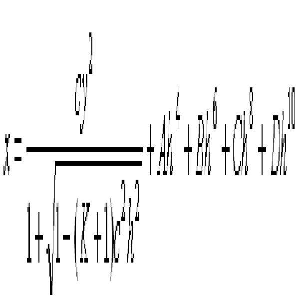
여기서, x는 렌즈의 정점으로부터 광축 방향으로의 거리이고, y는 광축에 대해 수직한 방향으로의 거리이며, K는 코닉상수(conic constant), A, B, C, D는 비구면계수, c는 렌즈의 정점에 있어서의 곡률반경의 역수(1/R)이다.Where k is a conic constant, A, B, C, and D are aspherical coefficients, and c is an aspherical coefficient. (1 / R) of the radius of curvature at the apex of the lens.
<제1실시예> ≪
도 1은 제1실시예에 따른 결상렌즈 시스템의 광학적 배치를 보인다. 결상렌즈 시스템은 물체측에서 상면측으로 순서대로 배치된 정의 굴절력의 제1렌즈군(G1), 조리개(ST) 및 정의 굴절력의 제2렌즈군(G2)을 포함한다. 제1렌즈군(G1)은 정렌즈인 제1렌즈(11), 정렌즈인 제2렌즈(21), 상측면이 오목하며, 부렌즈인 제3렌즈(31)를 포함한다. 제2렌즈군(G2)은 물체측면이 오목하며, 부렌즈인 제4렌즈(41), 정렌즈인 제5렌즈(51)를 포함한다. 제4렌즈(41)와 제5렌즈(51)는 서로 접합된 접합렌즈를 이루고 있다.Fig. 1 shows the optical arrangement of the imaging lens system according to the first embodiment. The imaging lens system includes a first lens group G1, a stop ST and a second lens group G2 of positive refractive power, which are arranged in order from the object side to the image side. The first lens group G1 includes a
제1실시예의 렌즈 데이터는 다음과 같다. The lens data of the first embodiment is as follows.
f ; 69.5 Fno ; 2.04 2ω; 23.0° f; 69.5 Fno; 2.04 2ω; 23.0 [deg.]
RDY THI nd ν RDY THI nd ν
OBJ: INFINITY D0 OBJ: INFINITY D0
1: 30.00000 5.880000 1.71300 53.94 1: 30.00000 5.880000 1.71300 53.94
2: 113.80000 0.150000 2: 113.80000 0.150000
3: 21.48000 4.900000 1.69680 55.46 3: 21.48000 4.900000 1.69680 55.46
4: 35.37000 1.525000 4: 35.37000 1.525000
5: 57.80000 1.500000 1.75520 27.53 5: 57.80000 1.500000 1.75520 27.53
6: 15.57000 7.280000 6: 15.57000 7.280000
ST: INFINITY 4.455000 ST: INFINITY 4.455000
8: -31.20000 1.500000 1.51424 63.90 8: -31.20000 1.500000 1.51424 63.90
ASP: ASP:
K : 0.000000 K: 0.000000
A :-.101711E-04 B :0.000000E+00 C :0.000000E+00 D :0.000000E+00 A: -. 101711E-04 B: 0.000000E + 00 C: 0.000000E + 00 D: 0.000000E + 00
9: 31.87000 5.800000 1.69680 55.46 9: 31.87000 5.800000 1.69680 55.46
10: -32.98000 D1 10: -32.98000 D1
11: INFINITY 3.000000 1.51680 64.20 11: INFINITY 3.000000 1.51680 64.20
12: INFINITY 1.000000 12: INFINITY 1.000000
IMG: INFINITY IMG: INFINITY
도 2는 본 발명의 제1실시예에 따른 결상렌즈 시스템의 종방향 구면수차(LONGITUDINAL SPHERICAL ABER.), 비점수차(ASTIGMATIC FIELD CURVES), 왜곡(DISTORTION)을 보이는 수차도이다. 종방향 구면수차는 파장이 656.27(nm), 587.56(nm), 486.13(nm)인 광에 대해 각각 나타내며, 비점수차, 왜곡은 파장 587.56(nm)인 광에 대해 나타낸다. 비점수차는 자오상면 (T: tangential field curvature)과 구결상면(S: sagittal field curvature)으로 나누어 보이고 있다. FIG. 2 is an aberration diagram showing a longitudinal spherical aberration, astigmatic field curves, and distortion of the image-forming lens system according to the first embodiment of the present invention. The longitudinal spherical aberration is shown for light having wavelengths of 656.27 (nm), 587.56 (nm), and 486.13 (nm), respectively, and astigmatism and distortion are shown for light having a wavelength of 587.56 (nm). The astigmatism is divided into tangential field curvature (T) and sagittal field curvature (S).
<제2실시예> ≪
도 3은 제2실시예에 따른 결상렌즈 시스템의 광학적 배치를 보인다. 결상렌즈 시스템은 물체측에서 상면측으로 순서대로 배치된 정의 굴절력의 제1렌즈군(G1), 조리개(ST) 및 정의 굴절력의 제2렌즈군(G2)을 포함한다. 제1렌즈군(G1)은 정렌즈인 제1렌즈(12), 정렌즈인 제2렌즈(22), 상측면이 오목하며, 부렌즈인 제3렌즈(32)를 포함한다. 제2렌즈군(G2)은 물체측면이 오목하며, 부렌즈인 제4렌즈(42), 정렌즈인 제5렌즈(52)를 포함한다. 제4렌즈(42)와 제5렌즈(52)는 서로 접합된 접합렌즈를 이루고 있다.3 shows the optical arrangement of the imaging lens system according to the second embodiment. The imaging lens system includes a first lens group G1, a stop ST and a second lens group G2 of positive refractive power, which are arranged in order from the object side to the image side. The first lens group G1 includes a
제2실시예의 렌즈 데이터는 다음과 같다. The lens data of the second embodiment is as follows.
f ; 54.51 Fno ; 2.83 2ω; 29.1°f; 54.51 Fno; 2.83 2ω; 29.1 [deg.]
RDY THI nd ν RDY THI nd ν
OBJ: INFINITY D0OBJ: INFINITY D0
1: 20.52000 3.900000 1.77250 49.621: 20.52000 3.900000 1.77250 49.62
2: 90.72000 0.1500002: 90.72000 0.150000
3: 18.60000 2.800000 1.59282 68.633: 18.60000 2.800000 1.59282 68.63
4: 26.65000 2.0100004: 26.65000 2.010000
5: 180.20000 1.500000 1.74077 27.765: 180.20000 1.500000 1.74077 27.76
6: 13.22000 4.2900006: 13.22000 4.290000
ST: INFINITY 4.060000ST: INFINITY 4.060000
8: -159.00000 1.200000 1.51680 64.208: -159.00000 1.200000 1.51680 64.20
9: 29.32000 3.090000 1.80420 46.509: 29.32000 3.090000 1.80420 46.50
10: -56.95000 D110: -56.95000 D1
11: INFINITY 2.940000 1.51680 64.2011: INFINITY 2.940000 1.51680 64.20
12: INFINITY 1.00000012: INFINITY 1.000000
IMG: INFINITY IMG: INFINITY
도 4는 본 발명의 제2실시예에 따른 결상렌즈 시스템의 종방향 구면수차(LONGITUDINAL SPHERICAL ABER.), 비점수차(ASTIGMATIC FIELD CURVES), 왜곡(DISTORTION)을 보이는 수차도이다.4 is an aberration diagram showing a longitudinal spherical aberration, astigmatical field curvature, and distortion of an image-forming lens system according to a second embodiment of the present invention.
<제3실시예> ≪ Third Embodiment >
도 5는 제3실시예에 따른 결상렌즈 시스템의 광학적 배치를 보인다. 결상렌즈 시스템은 물체측에서 상면측으로 순서대로 배치된 정의 굴절력의 제1렌즈군(G1), 조리개(ST) 및 정의 굴절력의 제2렌즈군(G2)을 포함한다. 제1렌즈군(G1)은 정렌즈인 제1렌즈(13), 정렌즈인 제2렌즈(23), 상측면이 오목하며, 부렌즈인 제3렌즈(33)를 포함한다. 제2렌즈(23)와 제3렌즈(33)는 서로 접합된 접합렌즈를 이루고 있다. 제2렌즈군(G2)은 물체측면이 오목하며 부렌즈인 제4렌즈(43)와, 정렌즈인 제5렌즈(53)를 포함한다. 제4렌즈(43)와 제5렌즈(53)는 서로 접합된 접합렌즈를 이루고 있다.5 shows the optical arrangement of the imaging lens system according to the third embodiment. The imaging lens system includes a first lens group G1, a stop ST and a second lens group G2 of positive refractive power, which are arranged in order from the object side to the image side. The first lens group G1 includes a
제3실시예의 렌즈 데이터는 다음과 같다. The lens data of the third embodiment is as follows.
f ; 54.54 Fno ; 2.47 2ω; 29.1°f; 54.54 Fno; 2.47 2ω; 29.1 [deg.]
RDY THI nd ν RDY THI nd ν
OBJ: INFINITY D0OBJ: INFINITY D0
1: 24.22000 3.400000 1.91082 52.50 1: 24.22000 3.400000 1.91082 52.50
2: 46.60000 0.150000 2: 46.60000 0.150000
3: 16.28000 4.730000 1.59282 68.633: 16.28000 4.730000 1.59282 68.63
4: 70.30000 1.500000 1.76182 26.614: 70.30000 1.500000 1.76182 26.61
5: 12.17000 5.300000 5: 12.17000 5.300000
ST: INFINITY 3.800000ST: INFINITY 3.800000
7: -21.50000 1.200000 1.51424 63.90 7: -21.50000 1.200000 1.51424 63.90
ASP: ASP:
K : 0.000000 K: 0.000000
A :-.182245E-04 B :0.000000E+00 C :0.000000E+00 D :0.000000E+00 A: - 182245E-04 B: 0.000000E + 00 C: 0.000000E + 00 D: 0.000000E + 00
8: 34.26000 3.920000 1.77250 49.628: 34.26000 3.920000 1.77250 49.62
9: -26.09000 D19: -26.09000 D1
10: INFINITY 2.940000 1.51680 64.2010: INFINITY 2.940000 1.51680 64.20
11: INFINITY 1.00000011: INFINITY 1.000000
IMG: INFINITY IMG: INFINITY
도 6은 본 발명의 제3실시예에 따른 결상렌즈 시스템의 종방향 구면수차(LONGITUDINAL SPHERICAL ABER.), 비점수차(ASTIGMATIC FIELD CURVES), 왜곡(DISTORTION)을 보이는 수차도이다.6 is an aberration diagram showing a longitudinal spherical aberration, an astigmatic field curvature, and a distortion of an image-forming lens system according to a third embodiment of the present invention.
<제4실시예> <Fourth Embodiment>
도 7은 제4실시예에 따른 결상렌즈 시스템의 광학적 배치를 보인다. 결상렌즈 시스템은 물체측에서 상면측으로 순서대로 배치된 정의 굴절력의 제1렌즈군(G1), 조리개(ST) 및 정의 굴절력의 제2렌즈군(G2)을 포함한다. 제1렌즈군(G1)은 정렌즈인 제1렌즈(14), 정렌즈인 제2렌즈(24), 상측면이 오목하며, 부렌즈인 제3렌즈(34)를 포함한다. 제2렌즈(24)와 제3렌즈(34)는 서로 접합된 접합렌즈를 이루고 있다. 제2렌즈군(G2)은 물체측면이 오목하며 부렌즈인 제4렌즈(44)와, 정렌즈인 제5렌즈(54)를 포함한다. 제4렌즈(44)와 제5렌즈(54)는 서로 접합된 접합렌즈를 이루고 있다.Fig. 7 shows the optical arrangement of the imaging lens system according to the fourth embodiment. The imaging lens system includes a first lens group G1, a stop ST and a second lens group G2 of positive refractive power, which are arranged in order from the object side to the image side. The first lens group G1 includes a
제4실시예의 렌즈 데이터는 다음과 같다. The lens data of the fourth embodiment is as follows.
f ; 69.50 Fno ; 2.85 2ω ; 23.0°f; 69.50 Fno; 2.85 2ω; 23.0 [deg.]
RDY THI nd ν RDY THI nd ν
OBJ: INFINITY D0 OBJ: INFINITY D0
1: 25.35000 4.210000 1.80420 46.50 1: 25.35000 4.210000 1.80420 46.50
2: 56.36000 0.1500002: 56.36000 0.150000
3: 16.80000 5.630000 1.49700 81.613: 16.80000 5.630000 1.49700 81.61
4: 68.53000 1.500000 1.67270 32.174: 68.53000 1.500000 1.67270 32.17
5: 12.63000 5.700000 5: 12.63000 5.700000
ST: INFINITY 4.990000ST: INFINITY 4.990000
7: -33.10000 1.500000 1.51424 63.907: -33.10000 1.500000 1.51424 63.90
ASP: ASP:
K : 0.000000 K: 0.000000
A :-.127225E-04 B :0.000000E+00 C :0.000000E+00 D :0.000000E+00 A: -. 127225E-04 B: 0.000000E + 00 C: 0.000000E + 00 D: 0.000000E + 00
8: 22.07000 4.320000 1.64850 53.038: 22.07000 4.320000 1.64850 53.03
9: -38.04000 D19: -38.04000 D1
10: INFINITY 2.940000 1.51680 64.2010: INFINITY 2.940000 1.51680 64.20
11: INFINITY 1.00000011: INFINITY 1.000000
IMG: INFINITYIMG: INFINITY
도 8은 본 발명의 제4실시예에 따른 결상렌즈 시스템의 종방향 구면수차(LONGITUDINAL SPHERICAL ABER.), 비점수차(ASTIGMATIC FIELD CURVES), 왜곡(DISTORTION)을 보이는 수차도이다.8 is an aberration diagram showing a longitudinal spherical aberration, an astigmatic field curvature, and a distortion of an image-forming lens system according to a fourth embodiment of the present invention.
다음 표는 실시예들이 상술한 조건들을 만족하는 것을 보인다.The following table shows that the embodiments meet the above conditions.
상술한 실시예들은 렌즈 매수를 최소화하고 적절한 후초점거리를 유지하면서 전체적으로 고른 품질의 광학 성능을 얻게 되며, 촬상소자의 고화소에 대응할 수 있는 결상렌즈 시스템을 제공하고 있다. 또한, 결상렌즈 시스템 전체의 이동에 의한 포커싱으로 포커싱시의 성능변화를 최소화하고 있다. The above-described embodiments provide an imaging lens system capable of coping with a high pixel of an imaging device, while achieving an overall optical performance of a uniform quality while minimizing the number of lenses and maintaining an appropriate focal length. Further, the focusing by the movement of the entire image forming lens system minimizes the change in performance at the time of focusing.
실시예들에 따른 결상렌즈 시스템은 이러한 결상렌즈 시스템을 통해 형성된 광학 상(optical image)을 전기 신호로 변환하는 촬상소자와 함께 다양한 종류의 촬상 장치에 채용될 수 있다.The imaging lens system according to the embodiments can be employed in various kinds of imaging apparatuses together with an imaging element that converts an optical image formed through such an imaging lens system into an electric signal.
이러한 본원 발명인 결상렌즈 시스템은 이해를 돕기 위하여 도면에 도시된 실시예를 참고로 설명되었으나, 이는 예시적인 것에 불과하며, 당해 분야에서 통상적 지식을 가진 자라면 이로부터 다양한 변형 및 균등한 타 실시예가 가능하다는 점을 이해할 것이다. 따라서, 본 발명의 진정한 기술적 보호 범위는 첨부된 특허청구범위에 의해 정해져야 할 것이다.Although the present invention has been described with reference to the embodiments shown in the drawings, it is to be understood that various changes and modifications may be made without departing from the scope of the present invention. I will understand that. Accordingly, the true scope of the present invention should be determined by the appended claims.
Claims (10)
물체측으로부터 순서대로 배치된, 정의 굴절력의 제1렌즈, 정의 굴절력의 제2렌즈 및 부의 굴절력을 가지며 상측이 오목한 제3렌즈로 이루어진, 정의 굴절력을 가지는 제1렌즈군;
물체측으로부터 순서대로 배치된, 물체측이 오목한 부렌즈인 제4렌즈와 정렌즈인 제5렌즈가 접합된 접합렌즈로 이루어진, 정의 굴절력을 가지는 제2렌즈군;을 포함하며,
상기 제2렌즈군의 가장 상측면에서 상면까지의 광축상의 공기 환산 거리를 fB, 전체 초점거리를 f라 할 때, 다음 조건을 만족하는 결상렌즈 시스템.
0.2≤fB/f≤0.7 In order from the object side to the image side,
A first lens group having a positive refractive power, which is composed of a first lens having positive refractive power, a second lens having positive refractive power, and a third lens having negative refractive power and having a concave upper side arranged in this order from the object side;
And a second lens group having a positive refractive power and made up of a cemented lens in which a fourth lens, which is a negative lens having an object side concave on its object side, and a fifth lens that is a positive lens are arranged in order from the object side,
And f is an air conversion distance on the optical axis from the most image side to the image plane of the second lens group, f is an overall focal length, and f is an overall focal length.
0.2? FB / f? 0.7
물체측으로부터 순서대로 배치된, 정의 굴절력의 제1렌즈, 정의 굴절력의 제2렌즈 및 부의 굴절력을 가지며 상측이 오목한 제3렌즈로 이루어진, 정의 굴절력을 가지는 제1렌즈군;
물체측으로부터 순서대로 배치된, 물체측이 오목한 부렌즈인 제4렌즈와 정렌즈인 제5렌즈가 접합된 접합렌즈로 이루어진, 정의 굴절력을 가지는 제2렌즈군;을 포함하며,
상기 제1렌즈군의 가장 물체측면에서 상면까지의 광축상의 거리를 LT, 전체 초점거리를 f라 할 때, 다음 조건을 만족하는 결상렌즈 시스템.
0.8 ≤ LT/f ≤ 1.3 In order from the object side to the image side,
A first lens group having a positive refractive power, which is composed of a first lens having positive refractive power, a second lens having positive refractive power, and a third lens having negative refractive power and having a concave upper side arranged in this order from the object side;
And a second lens group having a positive refractive power and made up of a cemented lens in which a fourth lens, which is a negative lens having an object side concave on its object side, and a fifth lens that is a positive lens are arranged in order from the object side,
Satisfies the following condition when a distance on the optical axis from the most object side surface to the image surface of the first lens group is L T and the total focal length is f.
0.8? L T / f? 1.3
상기 제1렌즈군의 가장 물체측면에서 상면까지의 광축상의 거리를 LT, 전체 초점거리를 f라 할 때, 다음 조건을 만족하는 결상렌즈 시스템.
0.8 ≤ LT/f ≤ 1.3 The method according to claim 1,
Satisfies the following condition when a distance on the optical axis from the most object side surface to the image surface of the first lens group is L T and the total focal length is f.
0.8? L T / f? 1.3
조리개가 상기 제1렌즈군과 상기 제2렌즈군 사이에 배치된 결상렌즈 시스템.3. The method according to claim 1 or 2,
And an aperture is disposed between the first lens group and the second lens group.
상기 제2렌즈군의 정렌즈의 d-선(587.56nm) 굴절률 및 상기 제2렌즈군의 부렌즈의 d-선(587.56nm) 굴절률을 각각 nd(p), nd(n) 라 할 때, 다음 조건을 만족하는 결상렌즈 시스템.
|nd(p)-nd(n)|≥ 0.13. The method according to claim 1 or 2,
(587.56 nm) refractive index of the positive lens of the second lens group and the d-line (587.56 nm) refractive index of the negative lens of the second lens group are denoted by n d (p) and n d The following condition is satisfied:
| n d (p) - n d (n) | ≥ 0.1
제2렌즈군은 적어도 한 면의 비구면을 포함하는 결상렌즈 시스템. 3. The method according to claim 1 or 2,
And the second lens group includes at least one aspherical surface.
상기 제2렌즈군의 가장 물체측 면이 비구면으로 된 결상렌즈 시스템.The method according to claim 6,
And the most object side surface of the second lens group is an aspherical surface.
상기 제2렌즈와 상기 제3렌즈가 접합렌즈를 이루는 결상렌즈 시스템. 3. The method according to claim 1 or 2,
And the second lens and the third lens form a cemented lens.
물체 위치가 무한대에서 근거리로 변할 때, 시스템 전체가 물체측으로 이동하며 포커싱을 행하는 결상렌즈 시스템. 3. The method according to claim 1 or 2,
Wherein when the object position changes from infinity to near, the entire system moves toward the object side and performs focusing.
상기 결상렌즈 시스템에 의해 형성된 광학상을 전기 신호로 변환하는 촬상 소자;를 포함하는 촬상 장치. An imaging lens system according to claim 1 or 2;
And an imaging device for converting an optical image formed by the imaging lens system into an electric signal.
Priority Applications (4)
| Application Number | Priority Date | Filing Date | Title |
|---|---|---|---|
| KR1020120014402A KR101932717B1 (en) | 2012-02-13 | 2012-02-13 | Imaging lens system |
| US13/540,839 US8810932B2 (en) | 2012-02-13 | 2012-07-03 | Imaging lens system |
| EP13152984.4A EP2626733B1 (en) | 2012-02-13 | 2013-01-29 | Imaging lens system |
| CN201310051161.9A CN103246051B (en) | 2012-02-13 | 2013-02-16 | Imaging lens system |
Applications Claiming Priority (1)
| Application Number | Priority Date | Filing Date | Title |
|---|---|---|---|
| KR1020120014402A KR101932717B1 (en) | 2012-02-13 | 2012-02-13 | Imaging lens system |
Publications (2)
| Publication Number | Publication Date |
|---|---|
| KR20130092846A KR20130092846A (en) | 2013-08-21 |
| KR101932717B1 true KR101932717B1 (en) | 2018-12-26 |
Family
ID=47750415
Family Applications (1)
| Application Number | Title | Priority Date | Filing Date |
|---|---|---|---|
| KR1020120014402A Active KR101932717B1 (en) | 2012-02-13 | 2012-02-13 | Imaging lens system |
Country Status (4)
| Country | Link |
|---|---|
| US (1) | US8810932B2 (en) |
| EP (1) | EP2626733B1 (en) |
| KR (1) | KR101932717B1 (en) |
| CN (1) | CN103246051B (en) |
Families Citing this family (55)
| Publication number | Priority date | Publication date | Assignee | Title |
|---|---|---|---|---|
| CN109040552B (en) | 2013-06-13 | 2021-06-22 | 核心光电有限公司 | Dual Aperture Zoom Digital Camera |
| US9857568B2 (en) | 2013-07-04 | 2018-01-02 | Corephotonics Ltd. | Miniature telephoto lens assembly |
| WO2015001440A1 (en) | 2013-07-04 | 2015-01-08 | Corephotonics Ltd. | Miniature telephoto lens assembly |
| US9392188B2 (en) | 2014-08-10 | 2016-07-12 | Corephotonics Ltd. | Zoom dual-aperture camera with folded lens |
| CN108761728B (en) * | 2014-09-05 | 2021-04-09 | 玉晶光电(厦门)有限公司 | Optical imaging lens and electronic device |
| WO2016108093A1 (en) | 2015-01-03 | 2016-07-07 | Corephotonics Ltd. | Miniature telephoto lens module and a camera utilizing such a lens module |
| TWI565966B (en) | 2015-07-24 | 2017-01-11 | 大立光電股份有限公司 | Optical camera group, image capturing device and electronic device |
| KR102117514B1 (en) | 2015-11-26 | 2020-06-01 | 삼성전기주식회사 | Optical Imaging System |
| KR101862451B1 (en) | 2016-01-27 | 2018-05-29 | 삼성전기주식회사 | Converter Lens System |
| KR102600453B1 (en) * | 2016-02-19 | 2023-11-10 | 삼성전자주식회사 | Optical lens assembly and electronic apparatus having the same |
| JP6824618B2 (en) * | 2016-03-31 | 2021-02-03 | 日本電産サンキョー株式会社 | Wide-angle lens |
| CN106443968B (en) * | 2016-09-23 | 2018-10-30 | 吉林大学 | Medium and long distance on-vehicle lens for vehicle target identification |
| JP2018072739A (en) * | 2016-11-02 | 2018-05-10 | 株式会社栃木ニコン | Imaging lens, optical apparatus, and method for manufacturing plate-like member |
| TWI594037B (en) | 2016-11-24 | 2017-08-01 | 大立光電股份有限公司 | Photographing lens assembly, image capturing unit and electronic device |
| KR101983187B1 (en) | 2016-12-20 | 2019-05-28 | 삼성전기주식회사 | Optical Imaging System |
| KR102557898B1 (en) * | 2016-12-20 | 2023-07-20 | 삼성전기주식회사 | Optical Imaging System |
| TWI613480B (en) | 2017-02-08 | 2018-02-01 | 大立光電股份有限公司 | Optical imaging system, imaging apparatus and electronic device |
| KR102357292B1 (en) * | 2017-02-17 | 2022-01-28 | 삼성전자주식회사 | Optical lens assembly and electronic apparatus having the same |
| KR102211704B1 (en) | 2017-02-23 | 2021-02-03 | 코어포토닉스 리미티드 | Folded camera lens designs |
| US11106018B2 (en) | 2017-07-07 | 2021-08-31 | Corephotonics Ltd. | Folded camera prism design for preventing stray light |
| CN113031219A (en) | 2017-07-23 | 2021-06-25 | 核心光电有限公司 | Folding lens kit |
| EP3759538B1 (en) | 2018-03-02 | 2025-12-24 | Corephotonics Ltd. | Spacer design for mitigating stray light |
| CN114609745B (en) | 2018-05-14 | 2024-07-19 | 核心光电有限公司 | Lens assembly |
| CN111290099B (en) * | 2018-12-10 | 2022-08-23 | 信泰光学(深圳)有限公司 | Imaging lens |
| JP7252247B2 (en) | 2019-01-03 | 2023-04-04 | コアフォトニクス リミテッド | Multi-aperture camera comprising at least one camera with two zoom states |
| JP7184338B2 (en) * | 2019-01-31 | 2022-12-06 | 株式会社コシナ | large aperture lens |
| KR102655458B1 (en) | 2019-02-25 | 2024-04-08 | 코어포토닉스 리미티드 | Multi-aperture cameras with at least one two state zoom camera |
| CN110351470B (en) * | 2019-07-31 | 2024-07-19 | 小光子(武汉)科技有限公司 | A camera module |
| CN114578520A (en) | 2019-08-21 | 2022-06-03 | 核心光电有限公司 | Lens assembly |
| US12072609B2 (en) | 2019-09-24 | 2024-08-27 | Corephotonics Ltd. | Slim pop-out cameras and lenses for such cameras |
| US11656538B2 (en) | 2019-11-25 | 2023-05-23 | Corephotonics Ltd. | Folded zoom camera module with adaptive aperture |
| WO2021140403A1 (en) | 2020-01-08 | 2021-07-15 | Corephotonics Ltd. | Multi-aperture zoom digital cameras and methods of using same |
| CN111158115B (en) * | 2020-02-24 | 2021-11-02 | 诚瑞光学(常州)股份有限公司 | Camera optics |
| KR102327737B1 (en) * | 2020-05-26 | 2021-11-17 | 삼성전기주식회사 | Optical Imaging System |
| KR102207278B1 (en) * | 2020-05-26 | 2021-01-25 | 삼성전기주식회사 | Optical Imaging System |
| KR102617779B1 (en) | 2020-05-30 | 2023-12-22 | 코어포토닉스 리미티드 | System and method for obtaining super macro images |
| JP7663591B2 (en) | 2020-07-22 | 2025-04-16 | コアフォトニクス リミテッド | Flex camera lens design |
| EP4425256A3 (en) | 2020-07-31 | 2024-12-04 | Corephotonics Ltd. | Folded macro-tele camera lens designs |
| US11966147B2 (en) | 2020-09-18 | 2024-04-23 | Corephotonics Ltd. | Pop-out zoom camera |
| KR102809802B1 (en) | 2020-11-05 | 2025-05-16 | 코어포토닉스 리미티드 | Scanning tele camera based on two optical path folding element field-of-view scanning |
| JP7575924B2 (en) | 2020-11-30 | 2024-10-30 | 株式会社タムロン | Optical system and imaging device |
| KR20250008791A (en) | 2020-12-01 | 2025-01-15 | 코어포토닉스 리미티드 | Folded camera with continuously adaptive zoom factor |
| CN115516357B (en) | 2021-01-25 | 2023-12-19 | 核心光电有限公司 | Thin pop-up wide camera lens |
| KR102712773B1 (en) | 2021-03-22 | 2024-09-30 | 코어포토닉스 리미티드 | Folded cameras with continuously adaptive zoom factor |
| CN113156631B (en) * | 2021-04-30 | 2024-08-02 | 中山联合光电科技股份有限公司 | Imaging lens and mobile device |
| EP4425233A3 (en) | 2021-06-23 | 2024-11-13 | Corephotonics Ltd. | Compact folded tele cameras |
| JP7254864B2 (en) * | 2021-09-03 | 2023-04-10 | シャープセンシングテクノロジー株式会社 | Optical system and camera module |
| CN113534419A (en) * | 2021-09-15 | 2021-10-22 | 宁波永新光学股份有限公司 | Clear on-vehicle optical imaging lens of superelevation |
| WO2023047202A1 (en) | 2021-09-23 | 2023-03-30 | Corephotonics Ltd. | Large aperture continuous zoom folded tele cameras |
| CN116009189B (en) * | 2021-10-21 | 2025-11-25 | 成都理想境界科技有限公司 | Optical imaging lens assembly, scanning display device and near-eye display device |
| CN119414562A (en) | 2021-11-02 | 2025-02-11 | 核心光电有限公司 | Camera module and mobile device |
| CN120315168A (en) | 2021-12-14 | 2025-07-15 | 核心光电有限公司 | Large aperture compact scan telephoto camera |
| WO2023148559A1 (en) | 2022-02-01 | 2023-08-10 | Corephotonics Ltd. | Slim pop-out tele camera lenses |
| US12348870B2 (en) | 2022-04-09 | 2025-07-01 | Corephotonics Ltd. | Spin-out 360-degree camera for smartphone |
| KR102785049B1 (en) | 2022-08-05 | 2025-03-21 | 코어포토닉스 리미티드 | System and method for a zoom digital camera having an automatically adjustable zoom field of view |
Citations (2)
| Publication number | Priority date | Publication date | Assignee | Title |
|---|---|---|---|---|
| JP2007065524A (en) | 2005-09-02 | 2007-03-15 | Nidec Copal Corp | Imaging lens |
| JP3964533B2 (en) * | 1998-03-19 | 2007-08-22 | マミヤ・デジタル・イメージング株式会社 | Medium telephoto lens |
Family Cites Families (24)
| Publication number | Priority date | Publication date | Assignee | Title |
|---|---|---|---|---|
| US3815974A (en) * | 1970-03-30 | 1974-06-11 | Canon Kk | Camera lens system with means for correcting aberrations |
| JPS5198020A (en) | 1975-02-25 | 1976-08-28 | ||
| JPS5310425A (en) | 1976-07-16 | 1978-01-30 | Minolta Camera Co Ltd | Objective lens system free from deterioration due to aberration during close-up photography |
| JPS53122423A (en) | 1977-03-31 | 1978-10-25 | Canon Inc | Compact photographic lens of large aperture |
| JPS5740218A (en) | 1980-08-22 | 1982-03-05 | Nippon Kogaku Kk <Nikon> | Large-aperture ratio long-focus lens |
| JP3103166B2 (en) * | 1991-11-26 | 2000-10-23 | 富士写真光機株式会社 | Macro lens with a long exit pupil |
| JPH05210048A (en) | 1992-01-31 | 1993-08-20 | Asahi Optical Co Ltd | Reading lens |
| JPH06242370A (en) | 1993-02-17 | 1994-09-02 | Canon Inc | Large aperture lens |
| JP3925747B2 (en) | 1997-03-27 | 2007-06-06 | フジノン株式会社 | Large aperture lens for low-light shooting |
| JP2005017506A (en) | 2003-06-24 | 2005-01-20 | Ricoh Co Ltd | Document reading lens, document reading lens unit, document reading device, and image forming apparatus |
| US7054076B2 (en) | 2004-03-11 | 2006-05-30 | Pinotage, L.L.C. | Lens assembly and optical imaging system using same |
| JP4824981B2 (en) | 2005-09-21 | 2011-11-30 | オリンパスイメージング株式会社 | Imaging optical system and interchangeable lens apparatus having the same |
| JP2007225960A (en) | 2006-02-24 | 2007-09-06 | Pentax Corp | Wide-angle lens system |
| JP4905653B2 (en) | 2006-03-28 | 2012-03-28 | ペンタックスリコーイメージング株式会社 | Medium telephoto lens system |
| JP4929902B2 (en) | 2006-07-27 | 2012-05-09 | 株式会社ニコン | Single focus lens and imaging apparatus having the same |
| CN100565269C (en) * | 2006-10-09 | 2009-12-02 | 亚洲光学股份有限公司 | Wide-angle lens |
| JP2009186791A (en) | 2008-02-07 | 2009-08-20 | Olympus Imaging Corp | Imaging optical system and imaging apparatus comprising the same |
| JP5422895B2 (en) | 2008-02-18 | 2014-02-19 | 株式会社ニコン | Lens system and optical apparatus having the same |
| JP5170658B2 (en) | 2008-04-11 | 2013-03-27 | 株式会社ニコン | PHOTOGRAPHIC LENS, OPTICAL APPARATUS HAVING THE PHOTOGRAPHIC LENS, AND IMAGE-FORMING METHOD |
| JP5505758B2 (en) | 2008-04-11 | 2014-05-28 | 株式会社ニコン | Photographic lens, optical device equipped with this photographic lens |
| JP5170660B2 (en) | 2008-04-11 | 2013-03-27 | 株式会社ニコン | PHOTOGRAPHIC LENS, OPTICAL APPARATUS HAVING THE PHOTOGRAPHIC LENS, AND IMAGE-FORMING METHOD |
| WO2010001943A1 (en) * | 2008-07-02 | 2010-01-07 | 株式会社ニコン | Lens system and optical device |
| JP5078818B2 (en) | 2008-09-19 | 2012-11-21 | ペンタックスリコーイメージング株式会社 | Bright photographing lens system and electronic imaging apparatus using the same |
| JP2011107450A (en) | 2009-11-18 | 2011-06-02 | Sony Corp | Imaging lens and imaging apparatus |
-
2012
- 2012-02-13 KR KR1020120014402A patent/KR101932717B1/en active Active
- 2012-07-03 US US13/540,839 patent/US8810932B2/en active Active
-
2013
- 2013-01-29 EP EP13152984.4A patent/EP2626733B1/en not_active Not-in-force
- 2013-02-16 CN CN201310051161.9A patent/CN103246051B/en not_active Expired - Fee Related
Patent Citations (2)
| Publication number | Priority date | Publication date | Assignee | Title |
|---|---|---|---|---|
| JP3964533B2 (en) * | 1998-03-19 | 2007-08-22 | マミヤ・デジタル・イメージング株式会社 | Medium telephoto lens |
| JP2007065524A (en) | 2005-09-02 | 2007-03-15 | Nidec Copal Corp | Imaging lens |
Also Published As
| Publication number | Publication date |
|---|---|
| CN103246051B (en) | 2017-05-17 |
| US8810932B2 (en) | 2014-08-19 |
| KR20130092846A (en) | 2013-08-21 |
| US20130208178A1 (en) | 2013-08-15 |
| EP2626733A1 (en) | 2013-08-14 |
| EP2626733B1 (en) | 2015-09-16 |
| CN103246051A (en) | 2013-08-14 |
Similar Documents
| Publication | Publication Date | Title |
|---|---|---|
| KR101932717B1 (en) | Imaging lens system | |
| KR101853808B1 (en) | Wide angle lens system and photographing device | |
| JP5616535B2 (en) | Imaging lens and imaging apparatus | |
| TWI416198B (en) | Optical imaging system | |
| KR102083931B1 (en) | Wide angle lens system | |
| CN111624747B (en) | Optical imaging system and imaging device | |
| US8953260B2 (en) | Telephoto lens system | |
| KR101914042B1 (en) | Wide angle lens and photographing lens having the same | |
| KR101932722B1 (en) | Zoom lens and photographing apparatus having the same | |
| US8724232B2 (en) | Zoom lens and photographing apparatus including the same | |
| KR20170059244A (en) | Photographic lens optical system | |
| TW201307885A (en) | Optical lens assembly for image taking | |
| JP5974101B2 (en) | Wide angle lens and imaging device | |
| WO2013099214A1 (en) | Imaging lens and imaging device | |
| KR20150135919A (en) | Zoom lens system | |
| US20160085049A1 (en) | Imaging lens and imaging apparatus | |
| JP2014219587A (en) | Imaging lens and imaging apparatus | |
| TW201310057A (en) | Optical lens assembly for image pickup | |
| KR101457415B1 (en) | Lens optical system | |
| KR20150068194A (en) | Zoom lens and photographing lens having the same | |
| JP2003241084A (en) | Imaging lens and imaging device using the same | |
| KR101880633B1 (en) | Zoom lens and photographing device having the same | |
| JP4827454B2 (en) | Zoom lens and imaging apparatus having the same | |
| KR20140124286A (en) | Wide angle lens system and photographing apparatus having the same | |
| KR20130056671A (en) | Wide angle lens system and photographing apparatus with the same |
Legal Events
| Date | Code | Title | Description |
|---|---|---|---|
| PA0109 | Patent application |
Patent event code: PA01091R01D Comment text: Patent Application Patent event date: 20120213 |
|
| PG1501 | Laying open of application | ||
| A201 | Request for examination | ||
| PA0201 | Request for examination |
Patent event code: PA02012R01D Patent event date: 20170207 Comment text: Request for Examination of Application Patent event code: PA02011R01I Patent event date: 20120213 Comment text: Patent Application |
|
| E902 | Notification of reason for refusal | ||
| PE0902 | Notice of grounds for rejection |
Comment text: Notification of reason for refusal Patent event date: 20180618 Patent event code: PE09021S01D |
|
| E701 | Decision to grant or registration of patent right | ||
| PE0701 | Decision of registration |
Patent event code: PE07011S01D Comment text: Decision to Grant Registration Patent event date: 20181203 |
|
| GRNT | Written decision to grant | ||
| PR0701 | Registration of establishment |
Comment text: Registration of Establishment Patent event date: 20181219 Patent event code: PR07011E01D |
|
| PR1002 | Payment of registration fee |
Payment date: 20181220 End annual number: 3 Start annual number: 1 |
|
| PG1601 | Publication of registration | ||
| PR1001 | Payment of annual fee |
Payment date: 20210927 Start annual number: 4 End annual number: 4 |
|
| PR1001 | Payment of annual fee |
Payment date: 20241219 Start annual number: 7 End annual number: 7 |