KR101930835B1 - A method and a system for producing combinational logic network based on gene expression - Google Patents
A method and a system for producing combinational logic network based on gene expression Download PDFInfo
- Publication number
- KR101930835B1 KR101930835B1 KR1020160160468A KR20160160468A KR101930835B1 KR 101930835 B1 KR101930835 B1 KR 101930835B1 KR 1020160160468 A KR1020160160468 A KR 1020160160468A KR 20160160468 A KR20160160468 A KR 20160160468A KR 101930835 B1 KR101930835 B1 KR 101930835B1
- Authority
- KR
- South Korea
- Prior art keywords
- binary
- gene
- module
- code
- codes
- Prior art date
- Legal status (The legal status is an assumption and is not a legal conclusion. Google has not performed a legal analysis and makes no representation as to the accuracy of the status listed.)
- Expired - Fee Related
Links
Images


Classifications
-
- G06F19/12—
-
- G06F19/28—
Landscapes
- Physics & Mathematics (AREA)
- Health & Medical Sciences (AREA)
- Life Sciences & Earth Sciences (AREA)
- Engineering & Computer Science (AREA)
- Bioinformatics & Cheminformatics (AREA)
- General Health & Medical Sciences (AREA)
- Biophysics (AREA)
- Bioinformatics & Computational Biology (AREA)
- Biotechnology (AREA)
- Evolutionary Biology (AREA)
- Measuring Or Testing Involving Enzymes Or Micro-Organisms (AREA)
- Medical Informatics (AREA)
- Spectroscopy & Molecular Physics (AREA)
- Theoretical Computer Science (AREA)
- Molecular Biology (AREA)
- Physiology (AREA)
- Bioethics (AREA)
- Databases & Information Systems (AREA)
Abstract
본 발명은 유전자 발현에 기반한 조합 논리 네트워크를 생성하는 방법 및 시스템에 관한 것이다. 본 발명에 따르면, 생물학적 네트워크 모델링에 있어서 복수 개의 시료에서 각 유전자의 발현 수준에 대한 대표값을 사용하는 대신, 모든 시료에서의 각 유전자의 발현 수준을 모두 반영하므로, 대상 경로에 대한 보다 정확한 모델링이 가능하다.The present invention relates to a method and system for generating combinational logic networks based on gene expression. According to the present invention, instead of using a representative value for the expression level of each gene in a plurality of samples in biological network modeling, more accurate modeling of the target path is performed because it reflects the expression level of each gene in all samples It is possible.

Description
본 발명은 유전자 발현에 기반한 조합 논리 네트워크를 생성하는 방법 및 시스템에 관한 것이다.The present invention relates to a method and system for generating combinational logic networks based on gene expression.
최근 DNA 칩 또는 마이크로어레이 기술의 발전으로 인해 수천 개의 유전자의 발현 정도를 동시에 측정할 수 있게 되었다. 이러한 마이크로어레이 데이터를 분석해서 암의 경과나 세포의 주기적 변화 등에 영향을 미치는 유전자들을 알아낼 수 있다.Recently, the development of DNA chip or microarray technology has made it possible to simultaneously measure the expression level of thousands of genes. These microarray data can be analyzed to identify genes that affect cancer progression or periodic changes in cells.
유전자와 유전자의 상관관계를 나타내는 네트워크를 유전자 조절 네트워크라 한다. 유전자 조절 네트워크를 연구하는 방법으로 부울 네트워크(Boolean network)가 있다. 이 방법은 유전자의 활동 수준을 두 가지 상태, 즉 on과 off로 놓는다. 어떠한 유전자의 조합이 한 유전자의 다음 단계 활동 수준을 결정하는가를 알아내기 위해 그들 간 상호정보를 활용한다. 이러한 조합이 밝혀지게 되면 유전자 조절 네트워크를 그릴 수 있고, 이때 각 정점(node)은 유전자를 나타내며, AND, OR, NOT과 같은 이진 관계가 그 유전자들을 연결하는 연결자(edge) 역할을 하게 된다. 통상적으로, 부울 네트워크는 시간 흐름에 따른 유전자 발현 양상을 기록한 데이터를 이용하는 동적 모델링에 이용되어 왔다. A network that shows the correlation between genes and genes is called a gene regulation network. There is a Boolean network as a way to study gene regulation networks. This method places the activity level of a gene in two states, on and off. Use mutual information among them to determine which combination of genes determines the level of activity of the next step in a gene. When this combination is revealed, a gene regulatory network can be drawn, in which each node represents a gene, and a binary relationship such as AND, OR, or NOT serves as an edge connecting the genes. Typically, a boolean network has been used for dynamic modeling using data recording gene expression patterns over time.
최근 차세대 시퀀싱 기반 유전체학 분야에서 수많은 cross-sectional 데이터 세트가 생성되어 축적되고 있다. 이와 같은 데이터 세트로부터 유전자 조절 네트워크를 보다 효율적으로 모델링하기 위한 방법이 요구된다.Numerous cross-sectional data sets have been generated and accumulated in the field of next-generation sequencing-based genomics. There is a need for a method for more efficiently modeling gene regulation networks from such data sets.
일 양상은 유전자 발현에 기반한 조합 논리 네트워크를 생성하는 방법을 제공한다.One aspect provides a method for generating a combinatorial logical network based on gene expression.
다른 양상은 유전자 발현에 기반한 조합 논리 네트워크 생성 시스템을 제공한다.Another aspect provides a combinatorial logic network generation system based on gene expression.
일 양상은 2 이상의 각 시료로부터 얻어진 2 이상의 유전자의 발현 수준을 나타내는 데이터로부터, 하나 이상의 입력 유전자 및 하나의 출력 유전자를 갖는 모듈을 생성하는 단계; 상기 데이터 중 생성된 모듈에 속하는 유전자의 발현 수준을 이진수로 변환하여 상기 모듈에 대한 이진수 코드를 생성하는 단계로서, 상기 코드가 입력 유전자의 발현 수준에 대응하는 부분코드A 및 출력 유전자의 발현 수준에 대응하는 부분코드B로 이루어지는 것인 단계; 생성된 이진수 코드 중 임의로 선택된 2종의 이진수 코드가 동일한 부분코드A 및 상이한 부분코드B를 가질 경우 그 2종의 이진수 코드를 각각 서로 다른 그룹에 위치시켜, 각 그룹에 포함된 이진수 코드가 부분코드A 및 그에 대응하는 단일의 부분코드B로 이루어지도록 하는, 이진수 코드의 그룹화 단계; 및 상기 그룹 중 일부 또는 전부에 대하여 각각 논리 회로(logic circuit)를 생성하는 단계를 포함하는, 유전자 발현에 기반한 조합 논리 네트워크를 생성하는 방법을 제공한다.One aspect includes generating a module having one or more input genes and one output gene from data representing expression levels of two or more genes obtained from two or more samples; Generating binary code for the module by converting the expression level of a gene belonging to a module generated in the data into a binary number and generating a binary code corresponding to the partial code A corresponding to the expression level of the input gene and the expression level of the output gene And a corresponding partial code B; When two arbitrarily selected binary codes of the generated binary codes have the same partial code A and different partial codes B, the two binary codes are placed in different groups, and the binary codes included in each group are divided into partial codes A and a corresponding single partial code B; And generating a logic circuit for each of a part or all of the groups. ≪ Desc / Clms Page number 2 >
본 명세서에서 용어 "모듈(module)"은 생물학적 네트워크를 구성하는 단위 유전자 집단으로, 커뮤니티, 클러스터, 또는 서브네트워크 등으로 명명될 수 있다. 상기 모듈은 입력 유전자 및 출력 유전자의 발현 수준에 의해 결정되는 논리 표현(logical expression)을 가질 수 있다. 상기 논리 표현은 단일 부울 연산자 또는 부울 연산자의 조합을 포함할 수 있다. 상기 논리 표현은 예를 들면, 0, 1, And(유전자 X, 유전자 Y), ~유전자 X, 또는 Or(유전자 X, 유전자 Y, 유전자 Z)와 같은 형태일 수 있다. As used herein, the term "module" is a group of unit genes that constitute a biological network, and may be referred to as a community, a cluster, or a subnetwork. The module may have a logical expression determined by an expression level of an input gene and an output gene. The logical representation may comprise a single Boolean operator or a combination of Boolean operators. The logical expression may be in the form of, for example, 0, 1, And (gene X, gene Y), ~ gene X, or Or (gene X, gene Y, gene Z).
상기 모듈은 문헌, 실험 측정치, 전사체 데이터베이스, 생물학적 경로 데이터베이스, 유전자 세트 분석 도구, 또는 그의 조합을 고려하여 생성될 수 있다. 상기 전사체 데이터베이스는 마이크로어레이 데이터베이스일 수 있다. 상기 마이크로어레이 데이터베이스는 예를 들면, NCBI 유래 Gene Expression Omnibus (GEO), EBI 유래 ArrayExpress, The Cancer Geonome Atlas (TCGA), ArrayTrack, Stanford Microarray database, 또는 Genevestigator일 수 있다. 상기 생물학적 경로 데이터베이스는 KEGG, Gene Ontology, 또는 BioCarta 등 통상의 기술자가 접근 및 이용할 수 있는 데이터베이스를 포함한다. 상기 유전자 세트 분석 도구는 DAVID, GSEA, 또는 PATHOME 등 통상의 기술자가 접근 및 이용할 수 있는 분석 도구를 포함한다. The module may be generated considering literature, experimental measurements, transcript database, biological pathway database, gene set analysis tool, or a combination thereof. The transcript database may be a microarray database. The microarray database may be, for example, Gene Expression Omnibus (GEO) from NCBI, ArrayExpress from EBI, The Cancer Geonome Atlas (TCGA), ArrayTrack, Stanford Microarray database, or Genevestigator. The biological pathway database includes a database accessible to and accessible to ordinary engineers such as KEGG, Gene Ontology, or BioCarta. The gene set analysis tool includes an analysis tool that can be accessed and used by ordinary technicians such as DAVID, GSEA, or PATHOME.
상기 방법에서 유전자 발현 수준의 이진수로의 변환은 변환 함수(transfer function)를 통해 이루어질 수 있다. 상기 변환 함수는 예를 들면, R 패키지 "Binarize" (Mundus et al., 2015)일 수 있다. 상기 모듈에 대한 이진수 코드는 예를 들면, 000, 010, 011, 또는 101과 같이 표현될 수 있다. 상기 코드는 입력 유전자의 발현 수준에 대응하는 부분코드A 및 출력 유전자의 발현 수준에 대응하는 부분코드B로 이루어진다. 예를 들어, 입력 유전자 X, 입력 유전자 Y, 및 출력 유전자 Z로 이루어진 모듈에서, X 및 Y의 발현 수준이 이진수로 변환된 값이 각각 0 및 1이고, Z의 발현 수준이 이진수로 변환된 값이 1일 경우, 이 모듈의 이진수 코드는 011이고, 부분코드A는 01이며, 부분코드B는 1이 된다.In this method, the conversion of gene expression levels to binary numbers can be accomplished through a transfer function. The transformation function may be, for example, the R package "Binarize" (Mundus et al., 2015). The binary code for the module may be expressed, for example, as 000, 010, 011, or 101. The code consists of a partial code A corresponding to the expression level of the input gene and a partial code B corresponding to the expression level of the output gene. For example, in a module composed of an input gene X, an input gene Y, and an output gene Z, the expression level of X and Y is 0 and 1, respectively, and the expression level of Z is converted into a binary number In this case, the binary code of this module is 011, the partial code A is 01, and the partial code B is 1.
상기 방법은 생성된 이진수 코드를 그룹화하는 단계를 포함한다. 그룹화 단계에서, 생성된 이진수 코드 중 임의로 선택된 2종의 이진수 코드가 동일한 부분코드A 및 상이한 부분코드B를 가질 경우 그 2종의 이진수 코드를 각각 서로 다른 그룹에 위치시킨다. 그 결과, 각 그룹에 포함된 이진수 코드에서 한 종류의 부분코드A에 대응하는 부분코드B는 단일한 값을 갖는다. The method includes grouping the generated binary codes. In the grouping step, if two arbitrarily selected binary codes of the generated binary codes have the same partial code A and different partial codes B, the two binary codes are placed in different groups. As a result, the partial code B corresponding to one type of partial code A in the binary code included in each group has a single value.
상기 방법은 생성된 그룹 중 일부 또는 전부에 대하여 각각 논리 회로를 생성하는 단계를 포함한다. 논리 회로는 입력값으로부터 출력값이 얻어지는 과정을 논리 기호로 표현한 표현 방식을 의미한다. 상기 논리 기호는 전자 공학 분야에서 통상적으로 사용되는 기호 또는 그를 변형한 것일 수 있다. The method includes generating a logic circuit for each or some of the generated groups. A logic circuit means a representation method in which a process of obtaining an output value from an input value is represented by a logic symbol. The logic symbol may be a symbol commonly used in the field of electronics or a modification thereof.
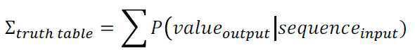
상기 방법은, 상기 각 그룹에 대하여 조건부 확률에 기반한 점수를 계산하는 단계를 더 포함할 수 있다. 상기 점수는 하기 수학식 1에 의해 계산될 수 있다.The method may further comprise calculating a score based on the conditional probability for each of the groups. The score can be calculated by the following equation (1).

상기 시료는 위암 환자로부터 수득된 것일 수 있다.The sample may be obtained from a gastric cancer patient.
상기 모듈 생성 단계에서 2 이상의 모듈이 생성될 경우, 상기 방법은 유전자의 발현 수준을 이진수로 변환하는 단계를 수행하기 전 대상 모듈을 선택하는 단계를 더 포함할 수 있다.When two or more modules are generated in the module generation step, the method may further include selecting the target module before performing the step of converting the gene expression level to binary number.
또한, 하나의 모듈에서의 출력 유전자가 다른 모듈의 입력 유전자가 되는 2 이상의 연속된 모듈에 상기 방법을 적용할 경우, 생물학적 네트워크 중 보다 광범위한 부분을 논리 회로에 의해 나타낼 수 있다. 이때, 각 모듈로부터 생성된 그룹 중 조건부 확률에 기반한 점수가 가장 높은 그룹에 대한 논리 회로를 연결하여 조합 논리 네트워크를 나타낼 수 있다.In addition, when applying the method to two or more contiguous modules in which the output gene in one module is the input gene of another module, a wider portion of the biological network can be represented by the logic circuit. At this time, among the groups generated from each module, a logic circuit for the group having the highest score based on the conditional probability can be connected to represent the combinational logic network.
도 1은 본 발명에 따른 조합 논리 네트워크 생성방법을 도시한 흐름도이다.1 is a flowchart illustrating a combinational logical network generation method according to the present invention.
다른 양상은, 2 이상의 각 시료로부터 얻어진 2 이상의 유전자의 발현 수준을 나타내는 데이터로부터, 하나 이상의 입력 유전자 및 하나의 출력 유전자를 갖는 모듈을 생성하는 모듈 생성부(110, 210); 상기 데이터 중 생성된 모듈에 속하는 유전자의 발현 수준을 이진수로 변환하여 상기 모듈에 대한 이진수 코드를 생성하는 이진수 변환부로서, 상기 코드가 입력 유전자의 발현 수준에 대응하는 부분코드A 및 출력 유전자의 발현 수준에 대응하는 부분코드B로 이루어지는 것인 이진수 변환부(120,220); 생성된 이진수 코드 중 임의로 선택된 2종의 이진수 코드가 동일한 부분코드A 및 상이한 부분코드B를 가질 경우 그 2종의 이진수 코드를 각각 서로 다른 그룹에 위치시켜, 각 그룹에 포함된 이진수 코드가 부분코드A 및 그에 대응하는 단일의 부분코드B로 이루어지도록 하는, 그룹 생성부(130, 230); 및 상기 그룹 중 일부 또는 전부에 대하여 각각 논리 회로를 생성하는 논리 회로 생성부(140, 240)를 포함하는, 유전자 발현에 기반한 조합 논리 네트워크 생성 시스템(100, 200)을 제공한다.In another aspect, a module generation unit (110, 210) for generating a module having one or more input genes and one output gene from data indicating the expression levels of two or more genes obtained from two or more samples; A binary code conversion unit for converting the expression level of a gene belonging to a module generated in the data into a binary number to generate a binary code for the module, the code comprising a partial code A corresponding to the expression level of the input gene, And a partial code B corresponding to the level of the partial code; When two arbitrarily selected binary codes of the generated binary codes have the same partial code A and different partial codes B, the two binary codes are placed in different groups, and the binary codes included in each group are divided into partial codes A and a single partial code B corresponding thereto; And a logic circuit generation unit (140, 240) for generating logic circuits for all or a part of the groups, respectively.
"…부" 등의 용어는 적어도 하나의 기능이나 동작을 처리하는 단위를 의미하며, 이는 하드웨어나 소프트웨어 또는 하드웨어 및 소프트웨어의 결합으로 구현될 수 있다. The term "part" or the like refers to a unit for processing at least one function or operation, which may be implemented by hardware, software, or a combination of hardware and software.
상기 모듈 생성부(110, 210)는 문헌, 실험 측정치, 전사체 데이터베이스, 생물학적 경로 데이터베이스, 유전자 세트 분석 도구, 또는 그의 조합을 고려하여 모듈을 생성할 수 있다. 시료, 모듈, 전사체 데이터베이스, 생물학적 경로 데이터베이스, 및 유전자 세트 분석 도구에 대해서는 전술된 바와 같다.The
상기 이진수 변환부(120, 220)는 유전자 발현 수준을 변환 함수를 통해 이진수로 변환하여 모듈에 대한 이진수 코드를 생성할 수 있다. 변환 함수 및 이진수 코드에 대해서는 전술된 바와 같다.The
상기 시스템(100, 200)은 이진수 코드를 그룹화하는 그룹 생성부(130, 230)를 포함한다. 그룹 생성부(130, 230)는, 임의로 선택된 2종의 이진수 코드가 동일한 부분코드A 및 상이한 부분코드B를 가질 경우 그 2종의 이진수 코드를 각각 서로 다른 그룹에 위치시켜, 각 그룹에 포함된 이진수 코드가 부분코드A 및 그에 대응하는 단일의 부분코드B로 이루어지게 할 수 있다.The
상기 시스템(100, 200)은 생성된 그룹 중 일부 또는 전부에 대하여 각각 논리 회로를 생성하는 논리 회로 생성부(140, 240)를 포함한다. 논리 회로에 대해서는 전술된 바와 같다.The
상기 시스템(200)은 생성된 각 그룹에 대하여 조건부 확률에 기반한 점수를 계산하는 점수 계산부(235)를 더 포함할 수 있다. 상기 점수 계산부(235)는 상기 수학식을 이용하여 각 그룹에 대한 점수를 계산할 수 있다.The
상기 모듈 생성부(110, 210)에서 2 이상의 모듈이 생성될 경우, 상기 시스템은 유전자의 발현 수준을 이진수로 변환하는 단계를 수행하기 전 대상 모듈을 선택하는 모듈 선택부를 더 포함할 수 있다.When two or more modules are generated in the
도 2a 및 2b는 본 발명에 따른 조합 논리 네트워크 생성 시스템을 도시한 도면이다.2A and 2B are diagrams illustrating a combinational logical network generation system according to the present invention.
본 발명에 따르면, 생물학적 네트워크 모델링에 있어서 복수 개의 시료에서 각 유전자의 발현 수준에 대한 대표값을 사용하는 대신, 모든 시료에서의 각 유전자의 발현 수준을 모두 반영하므로, 대상 경로에 대한 보다 정확한 모델링이 가능하다.According to the present invention, instead of using a representative value for the expression level of each gene in a plurality of samples in biological network modeling, more accurate modeling of the target path is performed because it reflects the expression level of each gene in all samples It is possible.
도 1은 본 발명에 따른 조합 논리 네트워크 생성방법을 도시한 흐름도이다.
도 2a 및 2b는 본 발명에 따른 조합 논리 네트워크 생성 시스템을 도시한 도면이다.
도 3은 PRICKLE1 및 PRICKLE2를 입력 유전자로 하고 VANGL2를 출력 유전자로 하는 모듈 VANGL2의 그래프화 표현을 나타낸다.
도 4는 위암 전사체 데이터 세트 GEO GSE15459의 유전자 발현 수준 및 이진수로 변환된 값을 나타낸다.
도 5는 모듈 VANGL2의 관측 테이블(observation table)을 나타낸다.
도 6은 모듈 VANGL2에 대하여 가능한 네 가지 조합 논리 네트워크를 진리 테이블, 점수, 및 논리 표현과 함께 나타낸 것이다.
도 7a 및 7b는 WNT 신호전달경로 중 WNT5A 및 WNT9A를 개시점으로 하고 VANGL1 및 VANGL2를 종결점으로 하는 하위 경로에 본 발명의 네트워크 모델을 적용한 결과를 나타낸다. 1 is a flowchart illustrating a combinational logical network generation method according to the present invention.
2A and 2B are diagrams illustrating a combinational logical network generation system according to the present invention.
Fig. 3 shows a graphical representation of the module VANGL2 using PRICKLE1 and PRICKLE2 as the input gene and VANGL2 as the output gene.
Figure 4 shows the gene expression levels and the values converted to binary numbers in the gastric cancer transcript data set GEO GSE15459.
Figure 5 shows an observation table of the module VANGL2.
Figure 6 shows four possible combinatorial logical networks for module VANGL2, with truth tables, scores, and logical representations.
FIGS. 7A and 7B show the results of applying the network model of the present invention to the lower path having WNT 5A and WNT 9A as start points and VANGL1 and VANGL2 as end points in the WNT signal propagation path.
이하, 본 발명을 하기 실시예에 의해 더욱 구체적으로 설명한다. 그러나, 이들 실시예는 본 발명에 대한 이해를 돕기 위한 것일 뿐, 어떤 의미로든 본 발명의 범위가 이들에 의해 제한되는 것은 아니다. Hereinafter, the present invention will be described in more detail with reference to the following examples. However, these embodiments are provided to aid understanding of the present invention, and the scope of the present invention is not limited thereto in any sense.
실시예: 위암 유전자 발현에 대한 조합 논리 네트워크 생성Example: Generation of a combinatorial logical network for gastric cancer gene expression
Lauren 분류에 따른 장형 위암(intestinal type gastric cancer) 환자 ...명(인종, 비교군, 프로파일링 플랫폼 기재 요망)의 mRNA 발현 데이터를 GEO accession GSE15459 데이터 세트로부터 수득하였다. R 패키지 "Binarize" (Mundus et al., 2015, "Binarize: Binarization of One-Dimensional Data.", Available from https://cran.r-project.org/package=Binarize) 유래의 BASC 알고리즘 (Hopfensitz, M. et al., 2012, IEEE/ACM Transactions on Computational Biology and Bioinformatics (TCBB) 9(2): 487-498)을 이용하여 이진값으로 변환하였다. MRNA expression data of patients with intestinal type gastric cancer according to the Lauren classification (race, comparative group, profiling platform requirement) were obtained from the GEO accession GSE15459 data set. R package "Binarize" (Mundus et al., 2015, "Binarize: Binarization of One-Dimensional Data." Available from https://cran.r-project.org/package=Binarize) (TCBB) 9 (2): 487-498), which was used to generate the binary data.
도 3은 PRICKLE1 및 PRICKLE2를 입력 유전자로 하고 VANGL2를 출력 유전자로 하는 모듈 VANGL2의 그래프화 표현을 나타낸다. Fig. 3 shows a graphical representation of the module VANGL2 using PRICKLE1 and PRICKLE2 as the input gene and VANGL2 as the output gene.
도 4는 위암 전사체 데이터 세트 GEO GSE15459의 유전자 발현 수준 및 이진수로 변환된 값을 나타낸다. 도 4의 (a)는 여러 시료에서 모듈 VANGL2에 속하는 유전자의 발현 수준을 나타내는 데이터이다. 도 4의 (b)는 (a)에 나타난 각 발현 수준이 BASC 알고리즘에 의해 이진수로 변환된 값을 나타낸다. 도 4의 (b)에서 무색은 발현 수준이 낮거나 발현되지 않는다는 것(이진수 0)을 나타내고, 흑색은 발현 수준이 높거나 발현된다는 것(이진수 1)을 나타낸다.Figure 4 shows the gene expression levels and the values converted to binary numbers in the gastric cancer transcript data set GEO GSE15459. 4 (a) is data showing the expression levels of genes belonging to the module VANGL2 in various samples. Figure 4 (b) shows the values of each expression level shown in (a) converted to binary numbers by the BASC algorithm. In Fig. 4 (b), colorless indicates that the expression level is low or not expressed (binary 0), and black indicates that the expression level is high or expressed (binary 1).
도 5는 모듈 VANGL2의 관측 테이블(observation table)을 나타낸다. 도 5에서 X는 "Don't-care term", 즉, 출력값이 입력값과 무관하다는 의미 또는 입력값이 환자에서 관찰되지 않는다는 의미를 나타낸다.Figure 5 shows an observation table of the module VANGL2. In Fig. 5, X denotes a "Don't-care term ", meaning that the output value is independent of the input value or that the input value is not observed in the patient.
도 5에 나타낸 바와 같이, 이 모듈은 이진수 코드로 000, 001, 01X, 100, 101, 및 110을 갖는다. 입력 유전자인 PRICKLE1 및 PRICKLE2에 대한 부분코드 00 및 10은 출력 유전자인 VANGL2에 대한 부분코드로 0과 1을 모두 가질 수 있고, PRICKLE1 및 PRICKLE2에 대한 부분코드 01은 VANGL2에 대한 부분코드로 X를 가지며, PRICKLE1 및 PRICKLE2에 대한 부분코드 11은 VANGL2에 대한 부분코드로 0을 갖는다. As shown in FIG. 5, this module has
PRICKLE1 및 PRICKLE2에 대한 부분코드 00 및 10이 VANGL2에 대한 부분코드로 0 또는 1을 가지므로, 각 그룹이 입력 유전자에 대한 부분코드 하나에 대하여 출력 유전자에 대한 부분코드로 단일한 값을 갖도록 도 3의 관측 테이블을 네 개의 서로 다른 진리 테이블(truth table)로 나누었다. The
각 진리 테이블에 대하여 파이썬(python) 라이브러리인 "PyEDA" (Drake, C, 2016, Retrieved September 19, 2016, Avaiable from https://github.com/cjdrake/pyeda)를 이용하여 축소된 부울 논리 표현을 나타내었다. 또한, 보다 많은 시료를 갖는 우세한 논리 표현을 구분하기 위하여, 각 진리 테이블에 대하여 조건부 확률에 기반한 점수를 하기 수학식 1에 따라 계산하였다.For each truth table, use the python library "PyEDA" (Drake, C, 2016, Retrieved September 19, 2016, Avaiable from https://github.com/cjdrake/pyeda) Respectively. Also, in order to distinguish predominant logical expressions with more samples, a score based on the conditional probability for each truth table was calculated according to
[수학식 1][Equation 1]

도 6은 모듈 VANGL2에 대하여 가능한 네 가지 조합 논리 네트워크를 진리 테이블, 점수, 및 논리 표현과 함께 나타낸 것이다. 도 6에 나타낸 바와 같이, 가장 높은 점수 2.75를 갖는 논리 표현은 0이다. 이는 PRICKLE1 및 PRICKLE2에 무관하게 VANGL2가 0이라는 것으로 해석될 수 있다. Figure 6 shows four possible combinatorial logical networks for module VANGL2, with truth tables, scores, and logical representations. As shown in Figure 6, the logical expression with the highest score 2.75 is zero. It can be interpreted that VANGL2 is 0 regardless of PRICKLE1 and PRICKLE2.
도 7a 및 7b는 WNT 신호전달경로 중 WNT5A 및 WNT9A를 개시점으로 하고 VANGL1 및 VANGL2를 종결점으로 하는 하위 경로에 본 발명의 네트워크 모델을 적용한 결과를 나타낸다. 도 7a는 WNT 신호전달경로 중 하위 경로를 나타내고 (Nam, Chang et al., Oncogene 33(41):4941-4951, 2014), 도 7b는 가장 높은 점수를 갖는 논리 표현에 해당하는 네트워크 구조로 연결된 조합 논리 네트워크 구조를 나타낸다. 각 모듈에 대한 나머지 논리 표현 및 그의 점수를 하기 표 1에 나타내었다.FIGS. 7A and 7B show the results of applying the network model of the present invention to the lower path having WNT 5A and WNT 9A as start points and VANGL1 and VANGL2 as end points in the WNT signal propagation path. 7a shows the lower path of the WNT signaling pathway (Nam, Chang et al., Oncogene 33 (41): 4941-4951, 2014) and FIG. 7b shows a network structure corresponding to the logical expression having the highest score Represents a combinatorial logical network structure. The remaining logical representations for each module and their scores are shown in Table 1 below.

이와 같이, 본 발명의 방법을 이용할 경우, 관심 있는 신호전달경로를 부울 표현을 이용하여 나타내는데 있어서, 노드에서의 대표값을 사용하는 대신, 모든 시료에서의 발현 수준을 반영할 수 있다.Thus, when using the method of the present invention, the signaling path of interest can be represented using a Boolean expression, which can reflect the expression level in all samples, instead of using the representative value at the node.
100, 200: 조합 논리 네트워크 생성 시스템
110, 210: 모듈 생성부
120, 220: 이진수 변환부
130, 230: 그룹 생성부
235: 점수 계산부
140, 240: 논리 회로 생성부100, 200: Combinational Logical Network Generation System
110 and 210:
120, and 220:
130, and 230:
235: score calculation unit
140, 240: a logic circuit generating section
Claims (10)
상기 데이터 중 생성된 모듈에 속하는 유전자의 발현 수준을 이진수로 변환하여 상기 모듈에 대한 이진수 코드를 생성하는 단계로서, 상기 코드가 입력 유전자의 발현 수준에 대응하는 부분코드A 및 출력 유전자의 발현 수준에 대응하는 부분코드B로 이루어지는 것인 단계;
생성된 이진수 코드 중 임의로 선택된 2종의 이진수 코드가 동일한 부분코드A 및 상이한 부분코드B를 가질 경우 그 2종의 이진수 코드를 각각 서로 다른 그룹에 위치시켜, 각 그룹에 포함된 이진수 코드가 부분코드A 및 그에 대응하는 단일의 부분코드B로 이루어지도록 하는, 이진수 코드의 그룹화 단계; 및
상기 그룹 중 일부 또는 전부에 대하여 각각 논리 회로(logic circuit)를 생성하는 단계를 포함하는, 유전자 발현에 기반한 조합 논리 네트워크를 생성하는 방법.Generating a module having one or more input genes and one output gene from the data indicating the expression levels of two or more genes obtained from two or more samples;
Generating binary code for the module by converting the expression level of a gene belonging to a module generated in the data into a binary number and generating a binary code corresponding to the partial code A corresponding to the expression level of the input gene and the expression level of the output gene And a corresponding partial code B;
When two arbitrarily selected binary codes of the generated binary codes have the same partial code A and different partial codes B, the two binary codes are placed in different groups, and the binary codes included in each group are divided into partial codes A and a corresponding single partial code B; And
Generating a logic circuit for each of the groups, and generating logic circuits for some or all of the groups.
상기 수학식에서,
In the above equation,
상기 데이터 중 생성된 모듈에 속하는 유전자의 발현 수준을 이진수로 변환하여 상기 모듈에 대한 이진수 코드를 생성하는 이진수 변환부로서, 상기 코드가 입력 유전자의 발현 수준에 대응하는 부분코드A 및 출력 유전자의 발현 수준에 대응하는 부분코드B로 이루어지는 것인 이진수 변환부;
생성된 이진수 코드 중 임의로 선택된 2종의 이진수 코드가 동일한 부분코드A 및 상이한 부분코드B를 가질 경우 그 2종의 이진수 코드를 각각 서로 다른 그룹에 위치시켜, 각 그룹에 포함된 이진수 코드가 부분코드A 및 그에 대응하는 단일의 부분코드B로 이루어지도록 하는, 그룹 생성부; 및
상기 그룹 중 일부 또는 전부에 대하여 각각 논리 회로를 생성하는 논리 회로 생성부를 포함하는, 유전자 발현에 기반한 조합 논리 네트워크 생성 시스템.A module generating unit for generating a module having one or more input genes and one output gene from the data indicating the expression levels of two or more genes obtained from two or more samples;
A binary code conversion unit for converting the expression level of a gene belonging to a module generated in the data into a binary number to generate a binary code for the module, the code comprising a partial code A corresponding to the expression level of the input gene, A partial code B corresponding to the level of the partial code;
When two arbitrarily selected binary codes of the generated binary codes have the same partial code A and different partial codes B, the two binary codes are placed in different groups, and the binary codes included in each group are divided into partial codes A and a corresponding single partial code B; And
And a logic circuit generation unit for generating logic circuits for a part or all of the groups, respectively.
Priority Applications (1)
| Application Number | Priority Date | Filing Date | Title |
|---|---|---|---|
| KR1020160160468A KR101930835B1 (en) | 2016-11-29 | 2016-11-29 | A method and a system for producing combinational logic network based on gene expression |
Applications Claiming Priority (1)
| Application Number | Priority Date | Filing Date | Title |
|---|---|---|---|
| KR1020160160468A KR101930835B1 (en) | 2016-11-29 | 2016-11-29 | A method and a system for producing combinational logic network based on gene expression |
Publications (2)
| Publication Number | Publication Date |
|---|---|
| KR20180060691A KR20180060691A (en) | 2018-06-07 |
| KR101930835B1 true KR101930835B1 (en) | 2018-12-19 |
Family
ID=62621195
Family Applications (1)
| Application Number | Title | Priority Date | Filing Date |
|---|---|---|---|
| KR1020160160468A Expired - Fee Related KR101930835B1 (en) | 2016-11-29 | 2016-11-29 | A method and a system for producing combinational logic network based on gene expression |
Country Status (1)
| Country | Link |
|---|---|
| KR (1) | KR101930835B1 (en) |
Citations (2)
| Publication number | Priority date | Publication date | Assignee | Title |
|---|---|---|---|---|
| JP2002520934A (en) | 1998-07-13 | 2002-07-09 | インターナショナル・ビジネス・マシーンズ・コーポレーション | Method and apparatus for reversibly mapping a binary sequence to a run-length limited coded sequence |
| JP2010068796A (en) | 2008-08-21 | 2010-04-02 | Sony Corp | Gene classifying method, gene classifying program, and gene classifying device |
Family Cites Families (2)
| Publication number | Priority date | Publication date | Assignee | Title |
|---|---|---|---|---|
| US5972693A (en) * | 1995-10-24 | 1999-10-26 | Curagen Corporation | Apparatus for identifying, classifying, or quantifying DNA sequences in a sample without sequencing |
| AU6638000A (en) * | 1999-08-13 | 2001-03-13 | Yale University | Binary encoded sequence tags |
-
2016
- 2016-11-29 KR KR1020160160468A patent/KR101930835B1/en not_active Expired - Fee Related
Patent Citations (2)
| Publication number | Priority date | Publication date | Assignee | Title |
|---|---|---|---|---|
| JP2002520934A (en) | 1998-07-13 | 2002-07-09 | インターナショナル・ビジネス・マシーンズ・コーポレーション | Method and apparatus for reversibly mapping a binary sequence to a run-length limited coded sequence |
| JP2010068796A (en) | 2008-08-21 | 2010-04-02 | Sony Corp | Gene classifying method, gene classifying program, and gene classifying device |
Also Published As
| Publication number | Publication date |
|---|---|
| KR20180060691A (en) | 2018-06-07 |
Similar Documents
| Publication | Publication Date | Title |
|---|---|---|
| AU2021282469B2 (en) | Deep learning-based variant classifier | |
| EP2390810B1 (en) | Taxonomic classification of metagenomic sequences | |
| Lei et al. | Assessing protein similarity with Gene Ontology and its use in subnuclear localization prediction | |
| US11288580B2 (en) | Optimal solution search method, optimal solution search program, and optimal solution search apparatus | |
| EP2963575B1 (en) | Data analysis device and method therefor | |
| García-Nieto et al. | Parallel multi-swarm optimizer for gene selection in DNA microarrays | |
| Zhu et al. | Identification of full and partial class relevant genes | |
| EP4145453A1 (en) | System for generating compound structure representation | |
| KR102493664B1 (en) | System and method for modelling prediction of herg induced cardiotoxicity | |
| Rusin et al. | Reconciliation of gene and species trees | |
| US20220172801A1 (en) | Training Device, Disease Affection Determination Device, Classification Device, Machine Learning Method, and Classification Method | |
| EP2518656B1 (en) | Taxonomic classification system | |
| KR101930835B1 (en) | A method and a system for producing combinational logic network based on gene expression | |
| Alexe et al. | Pattern-based clustering and attribute analysis | |
| US20180239866A1 (en) | Prediction of genetic trait expression using data analytics | |
| CN113591458B (en) | Medical term processing method, device, equipment and storage medium based on neural network | |
| JP2024040934A (en) | Sorting equipment, sorting methods, and sorting programs | |
| CN110265151B (en) | Learning method based on heterogeneous temporal data in EHR | |
| Bustamam et al. | Finding correlated biclusters from microarray data using the modified lift algorithm based on new residue score | |
| CN116779040B (en) | Data processing method based on multiple groups of chemical cancer subtype typing | |
| CN116469458B (en) | A Cell Cycle Prediction Method and System Based on Single-Cell Hi-C Data | |
| JP6332598B2 (en) | Feature selection method, information processing system, and computer program for efficient modeling of epistasis for phenotypic prediction | |
| Khan et al. | AI and Genomes for Decisions Regarding the Expression of Genes | |
| Ramadhani et al. | Neural network as a preferred method for microarray data classification | |
| EP4506848A1 (en) | Recommendation data generation device, recommendation data generation method, and non-transitory computer-readable medium |
Legal Events
| Date | Code | Title | Description |
|---|---|---|---|
| A201 | Request for examination | ||
| PA0109 | Patent application |
St.27 status event code: A-0-1-A10-A12-nap-PA0109 |
|
| PA0201 | Request for examination |
St.27 status event code: A-1-2-D10-D11-exm-PA0201 |
|
| D13-X000 | Search requested |
St.27 status event code: A-1-2-D10-D13-srh-X000 |
|
| D14-X000 | Search report completed |
St.27 status event code: A-1-2-D10-D14-srh-X000 |
|
| PG1501 | Laying open of application |
St.27 status event code: A-1-1-Q10-Q12-nap-PG1501 |
|
| E902 | Notification of reason for refusal | ||
| PE0902 | Notice of grounds for rejection |
St.27 status event code: A-1-2-D10-D21-exm-PE0902 |
|
| P11-X000 | Amendment of application requested |
St.27 status event code: A-2-2-P10-P11-nap-X000 |
|
| P13-X000 | Application amended |
St.27 status event code: A-2-2-P10-P13-nap-X000 |
|
| E701 | Decision to grant or registration of patent right | ||
| PE0701 | Decision of registration |
St.27 status event code: A-1-2-D10-D22-exm-PE0701 |
|
| GRNT | Written decision to grant | ||
| PR0701 | Registration of establishment |
St.27 status event code: A-2-4-F10-F11-exm-PR0701 |
|
| PR1002 | Payment of registration fee |
St.27 status event code: A-2-2-U10-U11-oth-PR1002 Fee payment year number: 1 |
|
| PG1601 | Publication of registration |
St.27 status event code: A-4-4-Q10-Q13-nap-PG1601 |
|
| P22-X000 | Classification modified |
St.27 status event code: A-4-4-P10-P22-nap-X000 |
|
| P22-X000 | Classification modified |
St.27 status event code: A-4-4-P10-P22-nap-X000 |
|
| P22-X000 | Classification modified |
St.27 status event code: A-4-4-P10-P22-nap-X000 |
|
| PR1001 | Payment of annual fee |
St.27 status event code: A-4-4-U10-U11-oth-PR1001 Fee payment year number: 4 |
|
| R18-X000 | Changes to party contact information recorded |
St.27 status event code: A-5-5-R10-R18-oth-X000 |
|
| PR1001 | Payment of annual fee |
St.27 status event code: A-4-4-U10-U11-oth-PR1001 Fee payment year number: 5 |
|
| R18-X000 | Changes to party contact information recorded |
St.27 status event code: A-5-5-R10-R18-oth-X000 |
|
| PC1903 | Unpaid annual fee |
St.27 status event code: A-4-4-U10-U13-oth-PC1903 Not in force date: 20231214 Payment event data comment text: Termination Category : DEFAULT_OF_REGISTRATION_FEE |
|
| R18-X000 | Changes to party contact information recorded |
St.27 status event code: A-5-5-R10-R18-oth-X000 |
|
| PC1903 | Unpaid annual fee |
St.27 status event code: N-4-6-H10-H13-oth-PC1903 Ip right cessation event data comment text: Termination Category : DEFAULT_OF_REGISTRATION_FEE Not in force date: 20231214 |
|
| R18-X000 | Changes to party contact information recorded |
St.27 status event code: A-5-5-R10-R18-oth-X000 |