KR101928575B1 - Piecewise planar reconstruction of three-dimensional scenes - Google Patents
Piecewise planar reconstruction of three-dimensional scenes Download PDFInfo
- Publication number
- KR101928575B1 KR101928575B1 KR1020117029924A KR20117029924A KR101928575B1 KR 101928575 B1 KR101928575 B1 KR 101928575B1 KR 1020117029924 A KR1020117029924 A KR 1020117029924A KR 20117029924 A KR20117029924 A KR 20117029924A KR 101928575 B1 KR101928575 B1 KR 101928575B1
- Authority
- KR
- South Korea
- Prior art keywords
- dimensional
- plane
- images
- scene
- image
- Prior art date
- Legal status (The legal status is an assumption and is not a legal conclusion. Google has not performed a legal analysis and makes no representation as to the accuracy of the status listed.)
- Expired - Fee Related
Links
Images


Classifications
-
- G—PHYSICS
- G06—COMPUTING OR CALCULATING; COUNTING
- G06T—IMAGE DATA PROCESSING OR GENERATION, IN GENERAL
- G06T15/00—3D [Three Dimensional] image rendering
-
- G—PHYSICS
- G06—COMPUTING OR CALCULATING; COUNTING
- G06T—IMAGE DATA PROCESSING OR GENERATION, IN GENERAL
- G06T15/00—3D [Three Dimensional] image rendering
- G06T15/005—General purpose rendering architectures
-
- G—PHYSICS
- G06—COMPUTING OR CALCULATING; COUNTING
- G06T—IMAGE DATA PROCESSING OR GENERATION, IN GENERAL
- G06T19/00—Manipulating 3D models or images for computer graphics
-
- G—PHYSICS
- G06—COMPUTING OR CALCULATING; COUNTING
- G06T—IMAGE DATA PROCESSING OR GENERATION, IN GENERAL
- G06T7/00—Image analysis
- G06T7/10—Segmentation; Edge detection
- G06T7/13—Edge detection
-
- G—PHYSICS
- G06—COMPUTING OR CALCULATING; COUNTING
- G06T—IMAGE DATA PROCESSING OR GENERATION, IN GENERAL
- G06T7/00—Image analysis
- G06T7/10—Segmentation; Edge detection
- G06T7/143—Segmentation; Edge detection involving probabilistic approaches, e.g. Markov random field [MRF] modelling
-
- G—PHYSICS
- G06—COMPUTING OR CALCULATING; COUNTING
- G06T—IMAGE DATA PROCESSING OR GENERATION, IN GENERAL
- G06T7/00—Image analysis
- G06T7/50—Depth or shape recovery
- G06T7/536—Depth or shape recovery from perspective effects, e.g. by using vanishing points
-
- G—PHYSICS
- G06—COMPUTING OR CALCULATING; COUNTING
- G06T—IMAGE DATA PROCESSING OR GENERATION, IN GENERAL
- G06T7/00—Image analysis
- G06T7/50—Depth or shape recovery
- G06T7/55—Depth or shape recovery from multiple images
-
- G—PHYSICS
- G06—COMPUTING OR CALCULATING; COUNTING
- G06T—IMAGE DATA PROCESSING OR GENERATION, IN GENERAL
- G06T2207/00—Indexing scheme for image analysis or image enhancement
- G06T2207/10—Image acquisition modality
- G06T2207/10028—Range image; Depth image; 3D point clouds
-
- G—PHYSICS
- G06—COMPUTING OR CALCULATING; COUNTING
- G06T—IMAGE DATA PROCESSING OR GENERATION, IN GENERAL
- G06T2207/00—Indexing scheme for image analysis or image enhancement
- G06T2207/20—Special algorithmic details
- G06T2207/20072—Graph-based image processing
-
- G—PHYSICS
- G06—COMPUTING OR CALCULATING; COUNTING
- G06T—IMAGE DATA PROCESSING OR GENERATION, IN GENERAL
- G06T2215/00—Indexing scheme for image rendering
- G06T2215/12—Shadow map, environment map
Landscapes
- Engineering & Computer Science (AREA)
- Physics & Mathematics (AREA)
- General Physics & Mathematics (AREA)
- Theoretical Computer Science (AREA)
- Computer Vision & Pattern Recognition (AREA)
- Computer Graphics (AREA)
- Software Systems (AREA)
- Probability & Statistics with Applications (AREA)
- Computer Hardware Design (AREA)
- General Engineering & Computer Science (AREA)
- Image Analysis (AREA)
- Image Processing (AREA)
Abstract
이차원 이미지들의 집합으로부터 삼차원 장면을 재구성하기 위한 방법, 시스템, 및 컴퓨터 판독가능 매체가 제공된다. 컴퓨터화된 재구성 시스템은 이차원 이미지들에 묘사된 환경의 시각적 특징을 모델링하기 위해 사용되는 후보 평면들을 식별하기 위해 이차원 이미지들의 집합에 컴퓨터 비전 알고리즘을 실행한다. 컴퓨터 비전 알고리즘은 이차원 이미지들의 픽셀들을 삼차원 장면 내 평면들로 할당하기 위해 이차원 이미지들의 특징들 사이의 관계 및 유사성을 표현하는 에너지 함수를 최소화할 수 있다. 삼차원 장면은 이동 가능하고 여러 이차원 이미지들 사이의 관점 전환을 묘사한다.A method, system, and computer readable medium for reconstructing a three-dimensional scene from a set of two-dimensional images is provided. The computerized reconstruction system implements a computer vision algorithm on the set of two dimensional images to identify candidate planes used to model the visual characteristics of the environment depicted in the two dimensional images. The computer vision algorithm can minimize the energy function expressing the relationship and similarity between the features of the two dimensional images to assign the pixels of the two dimensional images to the planar surfaces in the three dimensional scene. The three-dimensional scene is movable and depicts a perspective transition between several two-dimensional images.
Description
통상적으로, 컴퓨터의 렌더링 엔진은 이차원 이미지의 무질서한 집합으로부터 카메라 보정(calibration) 및 스파스(sparse) 구조를 복구하는 자동 피처(feature) 매칭 또는 특징 추출을 제공하도록 구성될 수 있다. 종래의 렌더링 엔진은 삼차원 공간 내 각 픽셀의 위치를 삼각으로 만들기 위해 카메라 보정, 스파스 장면 구조 및 이차원 이미지를 사용할 수 있다. 픽셀들은 삼차원 장면을 형성하도록 삼각으로 된 위치들로 렌더링된다. Typically, a computer's rendering engine may be configured to provide automatic feature matching or feature extraction that restores camera calibration and sparse structures from a disordered set of two-dimensional images. Conventional rendering engines can use camera calibration, sparse scene structures, and two-dimensional images to triangulate the location of each pixel in three-dimensional space. The pixels are rendered into triangular locations to form a three-dimensional scene.
그러나, 생성된 삼차원 장면의 품질과 디테일은 종종 다양한 결함들을 갖는다. 예를 들어, 종래의 렌더링 엔진은 이차원 이미지들로 캡처된 텍스처가 없는 표면이나 비램버시안(non-Lambertian) 표면을 홀(holes)로서 렌더링할 수 있다. 홀은 이웃하는 픽셀들의 깊이를 보간함으로써 메워진다. 그러나 종래의 렌더링 엔진의 보간은 직선들을 가진 평탄한 표면들을 삼차원 장면에서 울퉁불퉁한 표면으로서 잘못 재생할 수 있다. 종래의 렌더링 엔진은 또한 비램버시안 표면들, 폐색들(occlusions) 등의 신뢰할 수 없는 매칭으로 인해 삼차원 장면에 들쭉날쭉한 것들을 잘못 도입시킬 수도 있다. However, the quality and detail of the resulting three-dimensional scene often have various defects. For example, conventional rendering engines may render non-textured or non-Lambertian surfaces captured as two-dimensional images as holes. Holes are filled by interpolating the depths of neighboring pixels. However, the interpolation of a conventional rendering engine can erroneously reproduce flat surfaces with straight lines as rugged surfaces in a three-dimensional scene. Conventional rendering engines may also introduce erratic jaggies into the three-dimensional scene due to unreliable matching of non-Lambertian surfaces, occlusions, and the like.
종래의 렌더링 엔진의 품질 및 디테일은 건축구조 장면, 도시 장면, 또는 많은 평면 표면들을 가진 인공적 오브젝트들을 가진 장면들의 삼차원 장면들을 생성할 때 상당히 저하된다. 또한, 종래의 렌더링 엔진에 의해 실행되는 종래의 컴퓨터 비전(vision) 알고리즘의 추정사항들은 인공적 표면을 포함하는 장면들에 대해 잘 작동하도록 디자인되지 않았기 때문에 이차원 이미지들의 스파스 콜렉션(sparse colletion)으로부터의 삼차원 장면의 재구성은 포토리얼리즘 방식으로 조정될 수(navigable) 없다.
The quality and detail of a conventional rendering engine is significantly degraded when creating three-dimensional scenes of scenes having architectural structural scenes, urban scenes, or artificial objects with many planar surfaces. In addition, the estimates of conventional computer vision algorithms executed by conventional rendering engines are not designed to work well for scenes involving artificial surfaces, so that from sparse colletion of two-dimensional images Reconstruction of a three-dimensional scene is not navigable in a photorealistic way.
이 기술분야의 이러한 문제 및 다른 문제를 극복하는 본 발명의 실시예는 한가지 점에서 이차원 이미지들의 집합으로부터 이동성의(navigable) 포토리얼리즘적 장면들을 생성하는 컴퓨터화된 재구성 시스템, 컴퓨터 판독가능 매체, 및 컴퓨터 구현 방법에 관한 것이다. 컴퓨터화된 재구성 시스템은 이차원 이미지들의 집합으로부터 캡처된 장면의 밀집된 불연속 평면 재구성을 복구한다. SUMMARY OF THE INVENTION An embodiment of the present invention overcoming these and other problems in the art includes, in one aspect, a computerized reconstruction system, computer-readable medium, and computer readable medium for creating navigable photorealistic scenes from a set of two- To a computer implemented method. The computerized reconstruction system restores the dense discontinuous planar reconstruction of the captured scene from the set of two-dimensional images.
컴퓨터화된 재구성 시스템은 삼차원 평면 후보들의 이산(discrete) 집합을 식별한다. 컴퓨터화된 재구성 시스템은 이차원 이미지들의 집합에서 캡처된 여러 뷰(views)로부터 재구성된 스파스 삼차원 세그먼트들 및 해당 장면의 스파스 포인트 클라우드에 기반하여 삼차원 평면 후보들의 이산 집합을 생성한다. 이어서, 그래프-컷(graph-cut) 기반 에너지 최소화 기법을 이용하여 멀티-레이블(multi-label) MRF(Markov Random Field) 최적화를 해결함으로써 각 이미지에 대한 불연속 평면 깊이 맵이 복구된다. 컴퓨터화된 재구성 시스템은 오리지널 이차원 이미지들을 상기 복구된 평면 깊이 맵들 위로 투영하여 삼차원 장면의 렌더링을 생성한다.The computerized reconstruction system identifies a discrete set of three-dimensional planar candidates. The computerized reconstruction system creates a discrete set of 3D plane candidates based on the reconstructed sparse 3D segments and the sparse point cloud of the scene from the multiple views captured in the set of two dimensional images. The discontinuous plane depth map for each image is then recovered by resolving the multi-label MRF (Markov Random Field) optimization using a graph-cut based energy minimization technique. The computerized reconstruction system projects the original two dimensional images onto the restored planar depth maps to create a rendering of the three dimensional scene.
이 요약은 이하의 상세한 설명에 자세히 기술되는 간략한 형식의 개념들의 선택을 소개하기 위해 제공된다. 이 요약은 청구된 주제의 주요 특징이나 필수적 특징을 확인하도록 의도되거나 청구된 주제의 범위를 결정함에 있어 도움이 되는 것으로 분리되어 사용되도록 의도된 것이 아니다.
This summary is provided to introduce a selection of concepts in brief form which are described in detail in the following description. This summary is not intended to be used separately to aid in determining the scope of the subject matter intended or claimed to identify the essential or essential features of the claimed subject matter.
도 1은 본 발명의 실시예들에 따른 전형적인 컴퓨팅 시스템을 예시한 네트워크도이다.
도 2는 본 발명의 실시예들에 따른 전형적인 이차원 이미지들을 예시한 이미지도이다; 도 2a-2b는 본 발명의 실시예들에 따라, 카메라에 의해 캡처된 이차원 이미지들을 예시한다.
도 3은 본 발명의 실시예들에 따른 전형적인 삼차원 평명들을 예시한 평면 도면이다; 도 3a는 본 발명의 실시예들에 따른 삼차원 복원 구조(structure from motion) 특징 추출 및 카메라 보정 결정을 예시한다; 도 3b는 본 발명의 실시예들에 따라 컴퓨터화된 재구성 서버에 의해 생성된 삼차원 라인들을 예시한다; 도 3c-3e는 본 발명의 실시예에 따라 컴퓨터화된 재구성 서버에 의해 생성된 서로 다른 삼차원 관점을 위한 후보 평면들을 예시한다.
도 4는 본 발명의 실시예들에 따라 컴퓨팅 시스템에 의해 생성된 전형적 장면을 예시한 삼차원 장면도이다; 도 4a는 본 발명의 실시예들에 따라 컴퓨터화된 재구성 서버에 의해 생성된 깊이 맵을 예시한다; 도 4b는 본 발명의 실시예들에 따라 컴퓨터화된 재구성 서버에 의해 생성된 프록시 메쉬들을 예시한다; 도 4c는 본 발명의 실시예들에 따라 컴퓨터화된 재구성 서버에 의해 생성된 질감을 입힌 프록시 메쉬들을 예시한다.
도 5는 본 발명의 실시예들에 따른 전형적인 이차원 이미지들 안에서 소실 방향의 검출을 예시한 소실 방향에 대한 도면이다; 도 5a는 본 발명의 실시예에 따라, 소실 방향들을 추출하기 위해 컴퓨터화된 재구성 시스템에 의해 처리되는 전형적인 이차원 이미지를 예시한다; 도 5b는 본 발명의 실시예에 따라, 이차원 이미지로부터 추출된 소실 방향들의 각 클러스터의 방위를 예시한다; 도 5c는 본 발명의 실시예들에 따라 컴퓨터화된 서버에 의해 렌더링된 삼차원 장면의 전형적 재구성을 도시한다.
도 6은 본 발명의 실시예들에 따른 표면 법선들(normals)의 가능한 분포를 예시한 법선 방위도이다; 도 6a는 본 발명의 실시예들에 따른 삼차원 포인트들의 공분산의 크기를 예시한다; 도 6b는 본 발명의 실시예들에 따라 어떤 삼차원 포인트를 통과하는 평면들의 법선 분포를 예시한다.
도 7은 본 발명의 실시예들에 따른 평면들이나 삼차원 라인들의 방위의 가능한 분포를 예시한 분포 히스토그램이다; 도 7a는 본 발명의 실시예들에 따라, 삼차원 포인트들로부터의 표(votes)에 기초한 법선들의 분포를 나타낸 히스토그램을 예시한다; 도 7b는 본 발명의 실시예들에 따라, 삼차원 라인들로부터의 표(votes)에 기초한 법선들의 분포를 나타낸 히스토그램을 예시한다.
도 8은 본 발명의 실시예들에 따른 이차원 이미지들로부터 추출된 장면 정보를 예시한 가시성에 대한 도면이다.
도 9는 본 발명의 실시예들에 따라 MRF(Markov Random Field) 표현 및 그래프 컷 최소화를 이용하여 평면들을 나타내는 레이블들로의 픽셀들의 할당을 예시한 그래프 도면이다.
도 10은 본 발명의 실시예들에 따라 삼차원 장면들을 생성하는데 사용되는 이차원 이미지들 사이의 관계를 예시한 포토 일관성 도면이다; 도 10a는 본 발명의 실시예들에 따른 전형적인 기준 이미지를 예시한다; 도 10b는 본 발명의 실시예들에 따라 컴퓨터화된 시스템에 의해 사용되는 전형적인 서버에 의해 렌더링된 삼차원 장면의 전형적인 와핑된(warped) 이웃 이미지를 도시한다; 도 10c는 본 발명의 실시예들에 따라, 컴퓨터화된 재구성 서버에 의해 결정된 기준 이미지 및 와핑된 이미지 사이의 포토 일관성에 대한 계측을 예시한다.
도 11은 본 발명의 실시예들에 따라 삼차원 장면 내 한 쌍의 평면들의 교차에 해당하는 주름(crease) 에지들 및 평면들의 폐색(occlusion) 경계들을 예시하는 경계도이다; 도 11a는 본 발명의 실시예들에 따른 주름 에지들을 예시한다; 도 11b는 본 발명의 실시예들에 따른 폐색 경계들을 예시한다.
도 12a-b는 본 발명의 실시예들에 따라, 삼차원 놀이터 장면에서 관점들 간의 이동을 예시한 전환 도면들이다.
도 13a-b는 본 발명의 실시예들에 따라, 삼차원 차고 장면에서 관점들 간의 이동을 예시한 전환 도면들이다.
도 14a-b는 본 발명의 실시예들에 따라, 삼차원 아치 장면에서 관점들 간의 이동을 예시한 전환 도면들이다.
도 15a-b는 본 발명의 실시예들에 따라, 삼차원 성(castle) 장면에서 관점들 간의 이동을 예시한 전환 도면들이다.
도 16a-b는 본 발명의 실시예들에 따라, 삼차원 방 장면에서 관점들 간의 이동을 예시한 전환 도면들이다.
도 17a-e는 본 발명의 실시예들에 따라, 삼차원 로비 장면에서 관점들 간의 이동을 예시한 전환 도면들이다.
도 18은 본 발명의 실시예들에 따라 전자 데이터베이스에 저장되는 이미지들의 집합으로부터 이동성의 삼차원 장면을 렌더링하는데 사용되는 평면들의 선택 방법을 예시한 논리 도면이다.
도 19는 전자 데이터베이스에 저장된 이차원 이미지들의 집합으로부터 이동성의 삼차원 장면을 렌더링할 때 이차원 이미지들로부터 삼차원 평면들에 픽셀들을 할당하는 방법을 예시한 논리 도면이다. 1 is a network diagram illustrating an exemplary computing system in accordance with embodiments of the present invention.
Figure 2 is an image diagram illustrating exemplary two-dimensional images in accordance with embodiments of the present invention; 2A-2B illustrate two-dimensional images captured by a camera, in accordance with embodiments of the present invention.
Figure 3 is a top plan view illustrating exemplary three dimensional planar views in accordance with embodiments of the present invention; Figure 3A illustrates a structure from motion feature extraction and camera correction determination in accordance with embodiments of the present invention; Figure 3B illustrates three-dimensional lines generated by a computerized reconfiguration server in accordance with embodiments of the present invention; Figures 3C-3E illustrate candidate planes for different three-dimensional views generated by a computerized reconfiguration server in accordance with an embodiment of the present invention.
Figure 4 is a three dimensional scene diagram illustrating an exemplary scene generated by a computing system in accordance with embodiments of the present invention; Figure 4A illustrates a depth map generated by a computerized reconfiguration server in accordance with embodiments of the present invention; Figure 4b illustrates proxy meshes created by a computerized reconfiguration server in accordance with embodiments of the present invention; Figure 4c illustrates textured proxy meshes generated by a computerized reconfiguration server in accordance with embodiments of the present invention.
Figure 5 is a plot of the disappearance direction illustrating the detection of the disappearance direction in typical two-dimensional images in accordance with embodiments of the present invention; FIG. 5A illustrates an exemplary two-dimensional image processed by a computerized reconstruction system to extract missing directions according to an embodiment of the present invention; FIG. Figure 5B illustrates the orientation of each cluster of missing directions extracted from a two-dimensional image, according to an embodiment of the present invention; Figure 5C illustrates a typical reconstruction of a three-dimensional scene rendered by a computerized server in accordance with embodiments of the present invention.
Figure 6 is a normal orientation diagram illustrating a possible distribution of surface normals in accordance with embodiments of the present invention; Figure 6A illustrates the magnitude of the covariance of three-dimensional points according to embodiments of the present invention; 6B illustrates a normal distribution of planes passing through certain three-dimensional points in accordance with embodiments of the present invention.
Figure 7 is a distribution histogram illustrating a possible distribution of orientations of planes or three-dimensional lines according to embodiments of the present invention; Figure 7A illustrates a histogram illustrating the distribution of normals based on votes from three-dimensional points, in accordance with embodiments of the present invention; Figure 7B illustrates a histogram illustrating the distribution of normals based on votes from three-dimensional lines, in accordance with embodiments of the present invention.
8 is a diagram illustrating visibility of scene information extracted from two-dimensional images according to embodiments of the present invention.
9 is a graphical diagram illustrating allocation of pixels to labels representing planes using a Markov Random Field (MRF) representation and graph cut minimization in accordance with embodiments of the present invention.
Figure 10 is a photo-consistent view illustrating the relationship between two-dimensional images used to create three-dimensional scenes in accordance with embodiments of the present invention; Figure 10A illustrates an exemplary reference image in accordance with embodiments of the present invention; Figure 10B illustrates a typical warped neighbor image of a three-dimensional scene rendered by a typical server used by a computerized system in accordance with embodiments of the present invention; Figure 10C illustrates measurement of the photo-consistency between a reference image and a warped image as determined by a computerized reconfiguration server, in accordance with embodiments of the present invention.
Figure 11 is a boundary view illustrating occlusion boundaries of crease edges and planes corresponding to an intersection of a pair of planes in a three dimensional scene in accordance with embodiments of the present invention; 11A illustrates pleated edges according to embodiments of the present invention; 11B illustrates occlusion boundaries in accordance with embodiments of the present invention.
12A-B are transition diagrams illustrating movement between views in a three-dimensional playground scene, in accordance with embodiments of the present invention.
Figures 13A-B are transition diagrams illustrating movement between views in a three dimensional garage scene, in accordance with embodiments of the present invention.
14A-B are transition diagrams illustrating movement between views in a three-dimensional arch scene, in accordance with embodiments of the present invention.
15A-B are transition diagrams illustrating movement between views in a three-dimensional cast scene, in accordance with embodiments of the present invention.
16A-B are transition diagrams illustrating movement between views in a three-dimensional room scene, in accordance with embodiments of the present invention.
17A-e are transition diagrams illustrating movement between views in a three-dimensional lobby scene, in accordance with embodiments of the present invention.
18 is a logic diagram illustrating a method of selecting planes used to render a three-dimensional scene of mobility from a set of images stored in an electronic database in accordance with embodiments of the present invention.
19 is a logic diagram illustrating a method for allocating pixels from two-dimensional images to three-dimensional planes when rendering a three-dimensional scene of mobility from a set of two-dimensional images stored in an electronic database.
이 특허는 법정 요건을 만족하기 위해 구체적으로 특허될 내용을 기술한다. 그러나, 기술 자체가 이 특허의 범위를 한정하는 것으로 의도된 것은 아니다. 오히려 발명자들은 청구된 내용이 현재나 미래의 기술들과 연계되어 이 문서에 기술된 것들과 유사한 다른 단계나 단계들의 조합을 포함하는 다른 방식으로 실시될 수도 있다고 생각한다. 또한 "단계"와 "블록"이라는 용어는 여기 사용된 방법들의 서로 다른 요소들을 의미하는 것으로 사용될 수도 있지만, 개별 단계들의 순서가 명백히 기술될 때를 제외하고 여기 개시된 다양한 단계들 사이의 어떤 특정 순서를 의미하는 것으로 해석되어야 한다. 여기에 참조의 형식으로 전체적으로 포함되는 첨부된 도면을 참조하여 실시예들에 대한 설명이 이하에서 보다 상세히 이루어진다. This patent describes what will be patented specifically to satisfy the statutory requirements. However, the technology itself is not intended to limit the scope of this patent. Rather, the inventors believe that the claimed content may be implemented in other ways involving other steps or combinations of steps similar to those described in this document in conjunction with current or future technologies. It will also be understood that the terms " step " and " block " may be used to denote different elements of the methods used herein, but that the order of the individual steps may be any specific sequence between the various steps disclosed herein, Should be construed as meaning. BRIEF DESCRIPTION OF THE DRAWINGS A more complete understanding of the embodiments may be had by reference to the accompanying drawings, which are hereby incorporated by reference in their entirety.
본 발명이 실시예들은 이차원 이미지들의 집합으로부터 이동성의(navigable) 삼차원 장면들을 생성하는 컴퓨터화된 재구성 시스템을 제공한다. 매칭 특징들, 카메라 보정, 및 지리적 또는 공간적 정보를 추출하기 위해, 이차원 이미지들이 컴퓨터화된 재구성 시스템에 의해 처리된다. 그런 다음, 컴퓨터화된 재구성 시스템은 이차원 이미지들로부터 소실(vanishing) 방향들을 자동적으로 검출한다. 삼차원 장면을 위한 평면 후보들의 집합을 생성하기 위해 매칭 특징들, 카메라 보정사항, 공간적 정보, 및 소실 방향들이 컴퓨터화된 재구성 시스템에 의해 사용된다. 컴퓨터화된 재구성 시스템에 의해 평면 후보들의 집합에 대해 가능한 방위가 결정되고 MRF(Markov Random Field)가 생성된다. 다음으로, 이차원 이미지들로부터 후보 평면들에 픽셀들을 할당함으로써 이차원 이미지들로부터 삼차원 장면을 생성하기 위해 컴퓨터화된 재구성 시스템에 의해 MRF에 해당하는 최소화 함수가 사용된다. DETAILED DESCRIPTION OF THE PREFERRED EMBODIMENTS These embodiments of the present invention provide a computerized reconstruction system for generating navigable three-dimensional scenes from a set of two-dimensional images. In order to extract matching features, camera calibration, and geographic or spatial information, two-dimensional images are processed by a computerized reconstruction system. The computerized reconstruction system then automatically detects the vanishing directions from the two-dimensional images. Matching features, camera corrections, spatial information, and missing directions are used by the computerized reconstruction system to generate a set of planar candidates for a three dimensional scene. The computerized reconstruction system determines the possible orientation for the set of planar candidates and generates a Markov Random Field (MRF). Next, a minimization function corresponding to the MRF is used by the computerized reconstruction system to generate a three-dimensional scene from the two-dimensional images by assigning pixels to the candidate planes from the two-dimensional images.
당업자라면 컴퓨터화된 재구성 시스템이 하드웨어, 소프트웨어, 또는 하드웨어 및 소프트웨어의 조합을 포함할 수 있다는 것을 알 수 있을 것이다. 하드웨어는 메모리에 저장되는 명령어들을 실행하도록 구성된 프로세서 및 메모리를 포함한다. 일 실시예에서, 메모리는 컴퓨터 구현 방법을 위한 컴퓨터 사용가능 명령어들을 가진 컴퓨터 프로그램 제품을 저장하는 컴퓨터 판독가능 매체를 포함한다. 컴퓨터 판독가능 매체는 휘발성 및 비휘발성, 착탈형 및 비착탈형 양 매체, 및 데이터베이스, 스위치, 및 다양한 다른 네트워크 장치들에 의해 판독가능한 매체를 포함한다. 네트워크 스위치, 라우터, 및 관련 구성요소들은 이들과 통신하는 수단처럼 실제로 관례적이다. 한정이 아닌 예로서, 컴퓨터 판독가능 매체는 컴퓨터 저장 매체 및 통신 매체를 포함한다. 컴퓨터 저장 매체나 장치 판독가능 매체는 정보를 저장하기 위한 어떤 방법이나 기술을 통해 구현되는 매체를 포함한다. 저장된 정보의 예들에는 컴퓨터 사용가능 명령어, 데이터 구조, 프로그램 모듈 및 기타 데이터 표현이 포함된다. 컴퓨터 저장 매체는 RAM(random access memory), ROM(read only memory), EEPROM(electrically erasable programmable read only memory), 플래시 메모리나 다른 메모리 기술, CD-ROM(compact-disc read only memory), DVD(digital versatile discs), 홀로그램 매체나 다른 광 디스크 저장부, 마그네틱 카세트, 마그네틱 테이프, 마그네틱 디스크 저장부, 및 다른 마그네틱 저장 장치들을 포함하나 이들에 국한하지 않는다. 이 메모리 기술들은 데이터를 순간적으로, 임시로, 또는 영구적으로 저장할 수 있다. Those skilled in the art will appreciate that a computerized reconfiguration system may include hardware, software, or a combination of hardware and software. The hardware includes a processor and a memory configured to execute instructions stored in the memory. In one embodiment, the memory includes a computer readable medium storing a computer program product having computer usable instructions for a computer-implemented method. Computer readable media include both volatile and nonvolatile, removable and nonvolatile media, and media readable by databases, switches, and various other network devices. Network switches, routers, and related components are actually customary as the means for communicating with them. By way of example, and not limitation, computer readable media include computer storage media and communication media. Computer or device-readable media include media implemented through any method or technology for storing information. Examples of stored information include computer usable instructions, data structures, program modules, and other data representations. Computer storage media includes, but is not limited to, random access memory (RAM), read only memory (ROM), electrically erasable programmable read only memory (EEPROM), flash memory or other memory technology, compact disc read only memory (CD- versatile discs, holographic media or other optical disk storage, magnetic cassettes, magnetic tape, magnetic disk storage, and other magnetic storage devices. These memory technologies can store data instantaneously, temporarily, or permanently.
도 1은 본 발명의 일 실시예에 따른 전형적인 동작 환경(100)을 예시한 네트워크도이다. 도 1에 도시된 동작 환경(100)은 단지 예일 뿐이며 범위나 기능에 대한 어떤 한계를 제시하는 것으로 의도된 것은 아니다. 본 발명의 실시예들은 수많은 다른 구성들과 함께 작동될 수 있다. 도 1을 참조하면, 운영 환경(100)은 네트워크(113)를 통해 서로 통신하는 컴퓨터화된 재구성 서버(110), 이차원 이미지들(120), 삼차원 장면(130), 랩탑(140), 멀티미디어 캡처 장치(150 및 160), 파일 서버(170), 퍼스널 컴퓨터(180), 위성(190), 및 모바일 장치(195)를 포함한다. Figure 1 is a network diagram illustrating an
컴퓨터화된 재구성 서버(110)는 이동성의(navigable) 삼차원 장면(130)을 생성하도록 구성된다. 재구성 서버(110)는 평면 생성기(111), 최적화 엔진(112), 재구성 엔진(113) 및 멀티미디어 인덱스들(114)을 포함한다. 컴퓨터화된 재구성 시스템은 컴퓨팅 장치(가령, 랩탑(140), 멀티미디어 캡처 장치들(150 및 160), 파일 서버(170), 퍼스널 컴퓨터(180), 위성(190) 및 모바일 장치(195))로부터 삼차원 장면(130)을 생성하라는 요청을 수신할 수 있다. 그 요청에는 컴퓨터화된 재구성 서버(110)로 전송되는 이차원 이미지들(120)의 집합이 포함될 수 있다. 컴퓨터화된 재구성 서버는 이차원 이미지들(120)의 집합을 멀티미디어 인덱스들(114) 안에 저장한다. The
평면 생성기(111)는 카메라 및 이차원 이미지들(120)에 포함된 후보 평면들을 식별하도록 구성된다. 그런 다음 평면 생성기(111)는 각 후보 평면의 가능한 방위를 판단하고, 유사한 가능 방위들을 공유하는 후보 평면들을 무리짓는다. 일부 실시예들에서 평면 생성기(111)는 삼차원 장면(130)의 경계를 나타내기 위해 그라운드 평면 및 백(back) 평면을 생성한다. The
평면 생성기(111)는 이차원 이미지들(120)로부터 글로벌 장면 정보를 추출한다. 글로벌 장면 정보는 삼차원 포인트들 및 후보들, 소실(vanishing) 방향들, 삼차원 라인 세그먼트들, 및 삼차원 포인트들, 삼차원 라인들, 및 이차원 이미지들(120)에서 캡처된 장면의 여러 뷰들로부터 소실 방향들의 대응 관계 정도를 포함할 수 있다. 일 실시예에서, 평면 생성기(111)는 글로벌 장면 정보를 사용하여 후보 평면들을 검출할 수정된 RANSAC(Random Sample Consensus)을 실행한다. The
평면 생성기(111)는 이차원 이미지들(120)로부터 삼차원 포인트들 및 좌표들, 그리고 해당 장면을 캡처한 카메라에 의해 제공되는 어떤 관련 메타데이터를 추출한다. 카메라에 의해 제공된 메타데이터는 위치 정보, 거리 정보, 및 어떤 다른 카메라 보정 정보를 포함할 수 있다. 그에 따라, 평면 생성기(111)는 이차원 이미지 내 각 픽셀에 대한 공간적 삼차원 포인트를 생성하기 위해 메타데이터 및 이차원 이미지들(120)을 사용할 수 있다. 일부 실시예들에서, 평면 생성기(111)는 유사성에 기초하여 픽셀들을 수퍼 픽셀들로 그룹화한다. The
이차원 이미지들(120)에 의해 캡처된 장면에서 소실 방향들이 평면 생성기(111)에 의해 검출된다. 일 실시예에서, 이차원 이미지들(120) 내 소실 방향들을 검출하기 위해 평면 생성기(111)에 의해 에지(edge) 검출 알고리즘이 실행된다. 에지 검출 알고리즘은 이차원 이미지들(120)에 포함된 이차원 라인 세그먼트들을 제공한다. 이차원 라인 세그먼트들이 연결되어 이차원 이미지들의 집합 내 각 이미지에 대한 에지 맵(edge map)을 형성한다. 그리고 삼차원에서의 나란한 라인들에 상응하는 각 에지 맵 안의 라인들이나 라인 세그먼트들이 평면 생성기(111)에 의해 검출된다. 이미지들 안에서 소실 포인트들은 삼차원 장면의 소실 방향들에 해당한다. 평면 생성기(111)는 소실 방향들에 해당하는 벡터들의 단위 구(sphere)에 대해 평균 이동 클러스터링(mean-shift clustering)을 수행한다. 많은 수의 소실 방향들을 가진 클러스터들이 평면 생성기(111)에 의해 보유되고, 스파스(sparse) 클러스터들은 버려진다. 평면 생성기(111)는 각 클러스터에 포함된 장면의 여러 뷰들로부터 각각의 이차원 라인 세그먼트를 사용하여 그 클러스터의 대표적 소실 방향을 식별한다. 일부 실시예들에서 평면 생성기(111)는 서로 거의 직교하는 쌍들에 대해 소실 방향들의 집합을 검사하고, 그 집합 안에 직교하는 트리플릿(triplet)이 이미 존재하지 않는다면 그 직교하는 트리플릿을 완성하는 세 번째 소실 방향을 추가한다. The missing directions in the scene captured by the two-
매치하는 라인 세그먼트들을 식별하기 위해 에피폴라(epipolar) 구속조건 및 글로벌 장면 정보를 이용하는 평면 생성기(111)에 의해 삼차원 라인 세그먼트들이 구성된다. 평면 생성기(111)는 이차원 이미지에 의해 캡처된 장면 안에서 근위(proximal)의 당해 매칭 포인트들을 가지고 유사한 소실 방향들을 가진 이차원 라인 세그먼트들의 쌍들을 검색한다. 이차원 라인들의 여러 매칭 쌍들이 서로 연결되며, 평면 생성기(111)는 이차원 이미지에 의해 캡처된 장면의 여러 뷰들로부터 삼차원 라인을 위한 일치성을 확인한다. 일부 실시예들에서, 확인을 위해 사용되는 뷰의 개수는 적어도 넷이다. 이차원 세그먼트 쌍들을 삼각화하고 연결된 이차원 세그먼트들 안에서 전체적인 최소 역투영 오차(reprojection error)를 가지는 쌍을 찾음으로써 삼차원 라인들이 산출된다. 이어서 평면 생성기(111)는 구간 분석을 통해 삼차원 라인 세그먼트의 종점(endpoint)들을 결정한다. 일부 실시예들에서, 평면 생성기(111)는 식별된 소실 방향들에 의해 구속되지 않는 이차원 세그먼트들을 찾는다. 이러한 추가적 이차원 세그먼트들(아웃라이어들(outliers))은 그들의 방향과 분산에 기초하여 클러스터링된다. Dimensional line segments are constructed by a
평면 생성기(111)는 생성된 삼차원 라인들과 식별된 소실 방향들에 기초하여 각 삼차원 포인트의 평면 방위 및 가능한 위치를 결정한다. 소실 방향의 모든 쌍의 외적(cross-product)을 산정함으로써 평면 생성기(111)에 의해 가능성있는 평면 방위들의 집합 ![]()
![]()
![]()
![]()
![]()
![]()
![]()
![]()
각각의 삼차원 포인트의 가능한 위치가 평면 생성기(111)에 의해 결정된다. 일 실시예에서, 삼차원 포인트가 삼차원 라인들 및 소실 방향들에 의해 나타낸 한 개 이상의 평면 가설들에 속하는지 여부를 결정하기 위해 각각의 삼차원 포인트에 대한 삼차원 마할로노비스(Mahalonobis) 거리가 평면 생성기(111)에 의해 계산된다. 마할로노비스 거리는 삼차원 포인트 및 평면 가설의 해당 피팅 에러(fitting error)의 공분산(불확실성)을 판정한다. 소정 실시예들에서, 평면 생성기(111)는 이차원 이미지들(120)에 의해 캡처된 장면의 평균 뷰 방향을 따라 맞춰진 벡터 ![]()
![]()
![]()
![]()
![]()
![]()
각 삼차원 포인트 Xk의 표면 법선이 평면 방위들의 집합 ![]()
![]()
평면 생성기(111)에 의해 각각의 삼차원 포인트 및 삼차원 라인이 사용되어 이차원 이미지(120)에 의해 캡처된 장면의 평면들을 결정하도록 한다. 평면 생성기(111)는 삼차원 포인트들과 삼차원 라인들로부터 받은 각각의 방위 ![]()
![]()
![]()
![]()
![]()
![]()
![]()
![]()
일 실시예에서, 히스토그램 ![]()
![]()
![]()
![]()
![]()
![]()
각각의 삼차원 포인트 샘플 xk은 사이즈에 대한 적응적 가우시안(Gaussian) 커널 ![]()
![]()
![]()
![]()
![]()
![]()
![]()
![]()
![]()
![]()
각각의 삼차원 라인 샘플 yk은 사이즈에 대한 적응적 가우시안(Gaussian) 커널 ![]()
![]()
![]()
![]()
![]()
![]()
![]()
![]()
![]()
![]()
![]()
![]()
평면 생성기(111)는 두 히스토그램![]()
![]()
![]()
![]()
![]()
![]()
다른 실시예들에서, 평면 생성기(111)는 이차원 이미지들(120)에 의해 캡처된 장면의 아웃라이어(outlier) 부분을 위한 추가 평면들, 그라운드 평면들, 및 백 평면들을 제공한다. 아웃라이어 부분은 스파스 글로벌 장면 정보를 가진 이차원 이미지(120)의 영역이다. 평면 생성기(111)는 2-포인트 또는 3-포인트 RANSAC 알고리즘을 사용하여 삼차원 포인트들 및 소실 방향들의 무작위 샘플링을 실행할 수 있다. 이어서, 평면 생성기(111)에 의해 관련 삼차원 포인트들의 불확실성이 산출되고, 후보 평면들의 집합을 식별하도록 삼차원 포인트들을 통과하는 추가 평면들의 방위가 결정된다. In other embodiments, the
평면 생성기(111)는 또한 카메라에 의해 캡처된 이차원 이미지의 각각의 뷰에 대한 그라운드 평면 및 백 평면을 산출한다. 그라운드 평면은 카메라의 사이드(side) 벡터에 직교하는 업(up) 벡터를 선택함으로써 추정된다. 그라운드 평면은 업 벡터에 직교하고 평면 위에 위치하는 삼차원 포인트들의 95%를 가지는 평면으로서 식별된다. 그런 다음, 평면 생성기(111)는 삼차원 장면 내 그라운드를 더 잘 표현하기 위해 그라운드 평면을 개량한다. The
백 평면은 카메라의 광학 축에 직교하는 벡터를 선택함으로써 추정된다. 백 평면은 광학 축에 직교하고 평면 앞에 위치하는 삼차원 포인트들의 95%를 가지는 평면으로서 식별된다. 그런 다음, 평면 생성기(111)는 삼차원 장면 내 백 그라운드를 더 잘 표현하기 위해 백 평면을 최적화한다.The back plane is estimated by selecting a vector orthogonal to the optical axis of the camera. The back plane is identified as a plane having 95% of the three-dimensional points that are orthogonal to the optical axis and are located in front of the plane. The
최적화 엔진(112)은 평면 생성기(111)에 의해 제공된 후보 평면들을 사용하여 각각의 이차원 이미지에 대한 깊이 맵을 생성하도록 구성된다. 최적화 에진(112)은 이차원 이미지 내 픽셀들과 후보 평면들을 사용하여 MRF(Markov Random Field)를 생성한다. 최적화 엔진(112)은 픽셀들과 평면들을 나타내는 노드들을 가진 그래프를 생성한다. 그래프 또한 그래프의 노드들을 연결시키는 에지들을 포함하였다. 각각의 에지는 서로 다른 평면 레이블들을 에지가 연결하는 두 픽셀들에 할당하는 데 대한 페널티를 나타내는 비용과 결부된다. 최적화 엔진(112)은 이미지 내 픽셀들로의 평면 레이블 할당에 대한 일관성을 평가하는 목적 함수를 산정한다. 일부 실시예들에서, 최적화 엔진(112)은 픽셀들의 최적 레이블링을 결정하기 위해 에너지 함수 E를 이용한다.The
에너지 함수 E는 이웃 시스템과 기본 픽셀 데이터에 규정된 MRF의 사후 가능성 분포에 대한 로그 우도함수(log likelihood)를 나타낸다(가령, 4-연결 이웃은 모든 수직 및 수평 이웃 픽셀들을 고려한다). 최적화 엔진(112)은 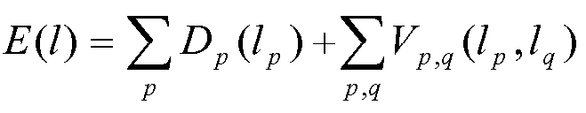
![]()
![]()
일부 실시예들에서, 최적화 엔진(112)은 평면들의 부분집합 ![]()
![]()
일 실시예에서, 최적화 에진(112)은 멀티-뷰 포토 일관성, 삼차원 포인트들과 라인들의 기하학적 근접성, 및 삼차원 포인트들 및 평면들의 광선 가시성(ray visibility)를 결합함으로써 Dp를 평가한다. Dp는 레이블 lp(즉, 평면 mp)를 픽셀 p에 할당하는 비용을 평가한다. ![]()
![]()
![]()
![]()
![]()
![]()
![]()
![]()
![]()
![]()
![]()
![]()
![]()
![]()
최적화 엔진(112)은 기준 이미지의 이웃 이미지들로부터 여러 뷰들을 선택함으로써 멀티 뷰 포토 일관성 ![]()
![]()
![]()
![]()
![]()
![]()

![]()
![]()
![]()
![]()
![]()
![]()
![]()
![]()
최적화 엔진(112)은 스파스 삼차원 포인트들 및 라인들 ![]()
![]()
![]()
![]()
![]()
![]()
최적화 엔진(112)은 삼차원 포인트들과 평면들 및 ![]()
![]()
![]()
![]()
![]()
![]()
삼차원 장면 내 경계들에서 픽셀들과 레이블들을 효율적으로 할당하기 위해 최적화 엔진(112)에 의해 평활화 항들 Vp ,q이 할당된다. 최적화 엔진(112)은 적절한 불연속성을 이용해 불연속 상수 레이블링을 장려한다. 평활화 항은 최적화 엔진(112)이 정확한 레이블 경계를 복구할 수 있게 하는 평면 구성 및 소실 방향들로부터 도출된 기하학적 구속조건들을 부과한다. 일부 실시예들에서, 최적화 엔진(112)은 삼차원 장면의 일부인 이차원 이미지들 속의 폐색 에지들과 주름 에지들을 식별하도록 구성된다. 삼차원 장면과 관련된 깊이 맵들은 평탄한 불연속성을 나타낼 수 있는 폐색 에지 및 주름 에지 둘 모두를 포함할 수 있다. 폐색 에지들에서 평면 레이블들 및 장면 깊이들 양자 모두는 폐색 에지를 지나는 픽셀들에서 상이하다. 폐색 에지들은 이차원 이미지들 내 어디에서나 일어날 수 있다. 그러나 평탄한 장면들에서 폐색 에지들은 통상적으로 이차원 이미지들 내 가시적인 이차원 라인 세그먼트들과 일치한다. 주름 에지들에서는 평면 레이블들만이 주름 에지에 걸친 픽셀들에 대해 상이하다. 한 쌍의 평면 레이블들 사이의 주름 에지는 두 개의 해당 평면의 삼차원 교차 라인의 투영과 일치하며, 그에 따라 항상 직선 세그먼트가 된다. Smoothing terms V p , q are assigned by the
다른 실시예에서, 최적화 엔진(112)은 이차원 이미지들의 집합 내 각각의 이차원 이미지에 대한 평면 기하구조를 동시에 추정한다. 추정된 삼차원 장면의 평면 기하구조는 불일치성을 보일 수 있다. 최적화 엔진(112)은 각각의 이차원 이미지 내 픽셀을 통과하는 광선을 삼차원 포인트를 찾기 위해 그 픽셀에 대응하는 후보 평면에 렌더링함으로써 불일치성을 검출한다. 최적화 엔진(112)은 삼차원 포인트를 이웃 이미지 내 픽셀로 재투영하여 그 삼차원 포인트에 대응하는 그 이웃 이미지 내 픽셀로 할당된 평면이 오리지널 이차원 이미지 내 후보 평면과 매치하는지를 판단할 수 있다. 최적화 엔진(112)은 불일치한 픽셀-평면 할당에 페널티를 주는 평활화 항들을 더하여 불일치성에 대처할 수 있다. 픽셀에서의 각각의 가능한 평면 선택을 위해, 평면을 이웃 이미지 내 대응 픽셀과 연결하는 평활화 항이 결정된다. 대응하는 이웃 픽셀의 픽셀-평면 할당이 불합치하면, 최적화 엔진(112)에 의해 활용된 최적화 함수에 의해 산출된 전반적 비용에 대해 평활화 항으로서 페널티가 추가된다. In another embodiment, the
일 실시예에서, 최적화 엔진(112)은 이차원 이미지들 내 라인 세그먼트들을 식별하여 폐색 에지들 및 주름 에지들을 검출한다. 이차원 라인 세그먼트들을 통과하는 레이블 경계들은 폐색 및 주름 에지들을 찾는 데 사용된다. 일부 실시예들에서, 직선 폐색 에지들에 대한 선호를 신호하기 위해 최적화 엔진에 의해 소실 방향들이 이용된다. In one embodiment, the
최적화 엔진(112)은 삼차원 장면 내 평활화 항들에 대한 불연속적 한계(definition)를 산정한다. 이웃 픽셀들(p, q)과 연관된 이웃 평면 lp 및 lq가 평활화 항들을 산정하는데 사용된다. The
lp=lq 이면 Vp ,q(lp,lq)=0.If l p = lq , V p , q (l p , l q ) = 0.

일부 실시예들에서, ![]()
![]()
![]()
![]()
최적화 엔진(112)은 평면들 M의 부분집합 내 모든 평면 쌍들(mi, mj)에 대한 주름 라인들 {Lij}의 집합을 결정하고, 이차원 이미지의 경계들 안에 있는 평면들 li 및 lj를 선택한다. 각각의 평면 li 및 lj에 대해, 최적화 엔진(112)은 이차원 이미지 내 이웃 픽셀들 (p,q)의 쌍들을 찾는데, 여기서 p와 q는 li 및 lj의 다른 측 상에 있다. 최적화 엔진(112)은 (p, q, li, lj)의 4-튜플(4-tuple) 조합을 가진 집합 S1을 생성한다. The
최적화 엔진(112)은 폐색 라인들의 집합 {Lik}을 결정한다. 각각의 평면 mi의 법선에 직교하는 소실 방향들이 폐색 라인들을 찾는데 사용된다. 식별된 소실 방향들을 지원하는 이차원 라인 세그먼트들은 이차원 이미지 내 이웃 픽셀들의 쌍들 (p, q)을 찾는데 사용되고, 여기서 p와 q는 li 및 lk의 다른 측 상에 있다. 최적화 엔진(112)은 (p, q, li, ll)의 4-튜플 조합을 가진 집합 S2를 생성한다. 집합 S2는 카메라로부터의 거리에 기반해 분류될 때 {mi} 너머에 있는 평면들 {mk}의 리스트를 얻기 위해 p와 q의 중간 포인트로부터 광선을 백 투영하는(back projects) 최적화 엔진(112)에 의해 채워진다. The
나머지 이차원 라인 세그먼트들이 최적화 엔진(112)에 의해 식별된다. 그리고 이차원 라인들을 지원하는 이웃 픽셀들 (p, q)의 집합 S3가 생성된다. 평활화 항은 최적화 엔진(112)이 삼차원 장면에 포함된 불연속성들을 이용해 평면들을 효과적으로 나타낼 수 있게 한다. The remaining two-dimensional line segments are identified by
재구성 엔진(113)은 삼차원 평면들 상에서의 최적화 및 최적화 엔진에 의해 제공된 관련 픽셀들에 기초하여 삼차원 장면 내에서의 이동(navigaiton)을 지원하도록 구성된다. 일 실시예에서, 그래프 컷 최적화가 이동성의 삼차원 장면을 생성하는데 사용되는 깊이 맵들과 프록시 메쉬들을 제공한다. 재구성 엔진(113)은 이차원 이미지들의 집합 내 각각의 레이블 이미지를 이차원 삼각측량으로 변환할 수 있다. 일부 실시예들에서, 재구성 엔진은 이차원 이미지의 삼각측량을 생성하기 위해 레이블 경계들 상에서 폴리 라인(polyline) 단순화를 이용한다. 그런 다음 재구성 엔진(113)에 의해 이차원 이미지들의 삼각측량이, 레이블들에 대응하는 평면들로부터 형성된 삼차원 삼각측량의 집합에 바로 매핑된다. The
이어서, 다중 이차원 이미지들 사이에서 뷰 보간을 가능하게 하기 위해 재구성 엔진(113)에 의해 투영 텍스처(projective texture)가 삼차원 삼각형들의 집합에 적용된다. 뷰 보간 중에, 재구성 엔진(113)은 각각의 이차원 이미지를 그 대응 프록시 메쉬들 상으로 투영 텍스처 매핑한다. The projective texture is then applied to the set of three-dimensional triangles by the
재구성 엔진(113)에 의해 수행되는 텍스처 매핑은 삼차원 장면을 나타내는, 섞여지고 교차 페이딩된(cross-faded) 평면들을 도출할 수 있다. 각 픽셀마다 섞여진 컬러들(C1, C2)이 재구성 엔진에 의해 다음과 같이 산정되어 정해진다: The texture mapping performed by the

또한,Also,

이다.to be.
재구성 엔진(113)은 전환 내내 완전한 불투명도로 렌더링될 한 소스 이미지에 의해서만 커버되는 삼차원 장면의 보간된 뷰들에서의 픽셀들을 이용한 전환을 제공하도록 구성된다. 재구성 엔진(113)은 뷰 보간 중에 다중 이미지들로부터의 기여분을 사용해 픽셀들을 선형적으로 교차 페이딩한다. 재구성 엔진(113)에 의해 수행되는 교차 페이딩은 뷰어가 다른 이차원 이미지에 의해 채워지는 이차원 이미지의 폐색 제거 영역들(disoccluded regions)에 초점을 맞추는 것을 막는다. The
사용자는 삼차원 장면을 재구성하는 컴퓨터화된 재구성 서버로 이차원 이미지들의 집합을 제공할 수 있다. 다른 대안으로서, 사용자는 로컬 컴퓨터 상에 위치한 이차원 이미지들로부터 삼차원 장면을 재구성하기 위해 로컬 컴퓨터 상에서 삼차원 재구성 프로그램을 실행할 수 있다. 삼차원 장면은 이동가능하며, 사용자에게 이차원 이미지들에 의해 캡처된 장면에 대한 몰입적 경험을 제공한다. A user can provide a set of two-dimensional images to a computerized reconfiguration server that reconstructs a three-dimensional scene. As another alternative, a user may run a three-dimensional reconstruction program on the local computer to reconstruct a three-dimensional scene from two-dimensional images located on the local computer. The three-dimensional scene is movable and provides the user with an immersive experience with the scene captured by the two-dimensional images.
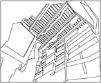
도 2는 본 발명의 실시예들에 따른 전형적인 이차원 이미지들을 예시한 이미지도이다. 이차원 이미지들은 어떤 집의 서로 다른 뷰들을 캡처한다. 일 실시예에서, 도 2a 및 2b의 이차원 이미지들이 카메라에 의해 캡처된다. 그런 다음, 그 이차원 이미지들은 삼차원 장면을 생성하기 위해 컴퓨터화된 재구성 서버에 의해 처리된다. 2 is an image diagram illustrating exemplary two-dimensional images in accordance with embodiments of the present invention. Two-dimensional images capture different views of a house. In one embodiment, the two-dimensional images of Figs. 2a and 2b are captured by the camera. The two-dimensional images are then processed by a computerized reconfiguration server to create a three-dimensional scene.
일부 실시예들에서, 삼차원 장면은 이미지 특징들과 카메라 보정사항들을 추출하기 위해 각각의 이차원 이미지에 대해 삼차원 복원 기술(structure from motion)을 수행함으로써 재구성된다. 그런 다음, 삼차원 장면의 후보 평면들을 식별하기 위해 그 이미지 특징들과 카메라 보정사항들이 컴퓨터화된 재구성 서버에 의해 사용된다. 평면 후보들이 컴퓨터화된 재구성 서버에 의해 조직되고 삼차원 장면 안에서 전반적인 글로벌 일관성에 기반해 렌더링된다.In some embodiments, the three-dimensional scene is reconstructed by performing a three-dimensional reconstruction technique (structure from motion) on each two-dimensional image to extract image features and camera corrections. The image features and camera corrections are then used by the computerized reconfiguration server to identify the candidate planes of the three dimensional scene. Planar candidates are organized by a computerized reconfiguration server and rendered based on overall global consistency within the 3D scene.
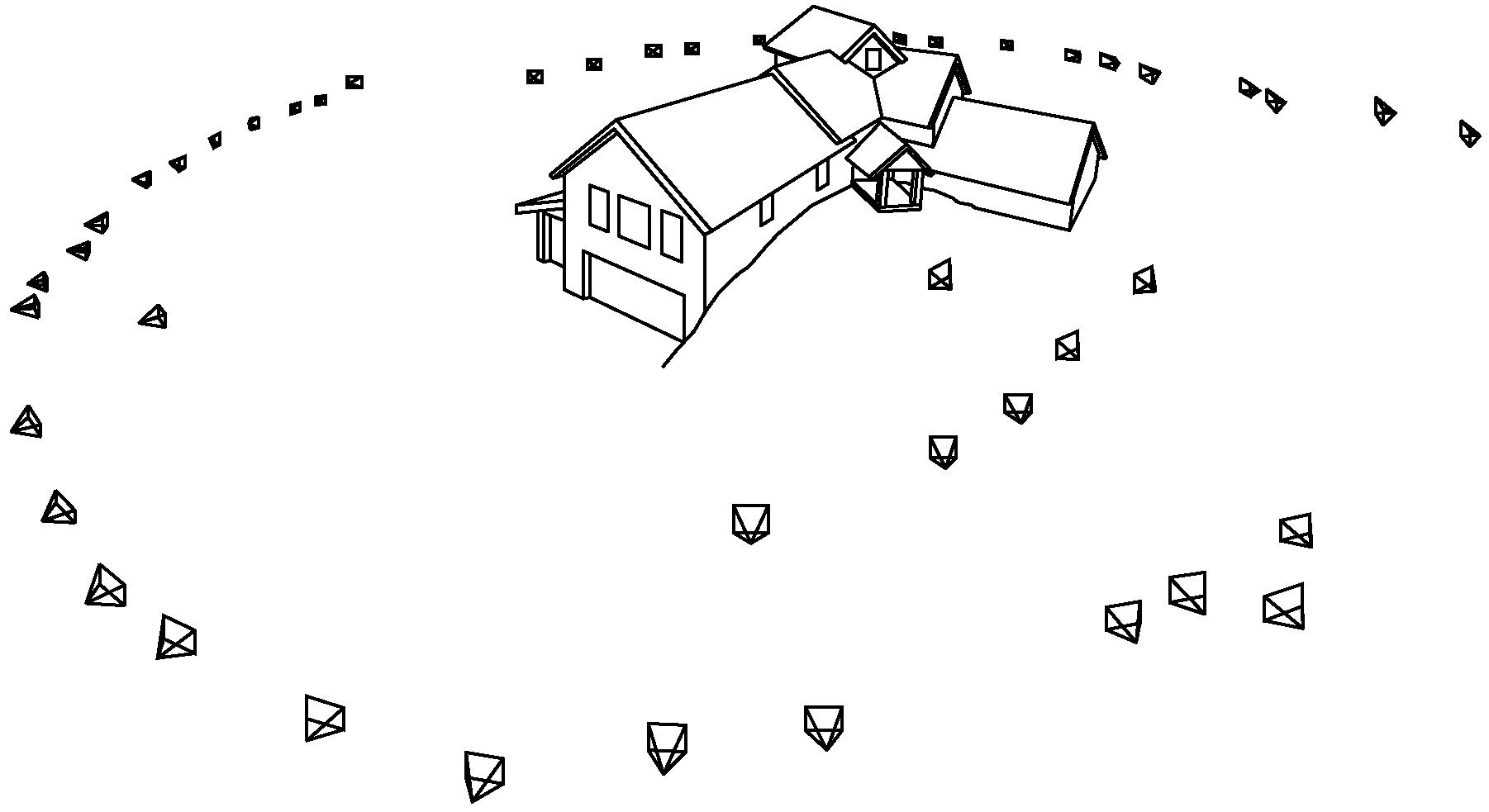
도 3은 본 발명의 실시예들에 따른 전형적인 삼차원 평명들을 예시한 평면 도면이다. 도 3a는 장면의 서로 다른 뷰들을 캡처하는 이차원 이미지들에 대해 컴퓨터화된 재구성 서버에 의해 수행되는 삼차원 복원 구조(structure from motion) 특징 추출 및 카메라 보정 결정을 예시한다. 이미지 특징들(가령, 라인, 포인트, 컬러, 픽셀 등)과 카메라 보정사항들(가령, 방위, 위치 등)은 삼차원 라인들과 평면들을 생성하는데 사용된다. 도 3b는 컴퓨터화된 재구성 서버에 의해 생성된 삼차원 라인들을 예시한다. 도 3c-3e는 컴퓨터화된 재구성 서버에 의해 생성되는 여러 삼차원 관점의 후보 평면들을 예시한다. 3 is a plan view illustrating exemplary three dimensional planar views in accordance with embodiments of the present invention. 3A illustrates a structure from motion feature extraction and camera correction determination performed by a computerized reconstruction server for two dimensional images capturing different views of a scene. Image features (e.g., lines, points, colors, pixels, etc.) and camera corrections (e.g., orientation, position, etc.) are used to create the three-dimensional lines and planes. Figure 3b illustrates three-dimensional lines generated by a computerized reconfiguration server. Figures 3C-3E illustrate candidate planes of various three dimensional views generated by a computerized reconfiguration server.
컴퓨터화된 재구성 서버는 이미지 특징들 및 카메라 보정사항들에 기반하여 삼차원 장면의 깊이 맵과 프록시 메쉬를 생성한다. 그런 다음, 추정된 삼차원 평면들, 깊이 맵들, 및 프록시 메쉬들을 이용하여 삼차원 장면이 렌더링된다. 어떤 실시예에서, 컴퓨터화된 재구성 시스템은 삼차원 장면을 컬러화하고 삼차원 장면들과 관련된 관점들 사이의 전환을 제공한다. The computerized reconstruction server creates a depth map and a proxy mesh of the three-dimensional scene based on the image features and camera corrections. The 3D scene is then rendered using the estimated 3D planes, depth maps, and proxy meshes. In some embodiments, the computerized reconstruction system colorizes the three dimensional scene and provides a transition between views associated with the three dimensional scenes.
도 4는 본 발명의 실시예들에 따라 컴퓨팅 시스템에 의해 생성된 전형적 장면을 예시한 삼차원 장면도이다. 컴퓨터화된 재구성 시스템은 삼차원 장면의 뷰들을 위해 도 4a에 도시된 깊이 맵을 생성한다. 그런 다음, 삼차원 장면에 텍스처를 제공하기 위해 컴퓨터화된 재구성 시스템에 의해 프록시 메쉬들이 사용된다. 프록시 메시들이 도 4b에 예시된다. 컴퓨터화된 재구성 서버는 또한 프록시 메쉬들에 대해 텍스처 매핑을 수행한다. 텍스처 매핑된 프록시 메쉬가 도 4c에 예시된다.4 is a three-dimensional scene diagram illustrating an exemplary scene generated by a computing system in accordance with embodiments of the present invention. The computerized reconstruction system generates the depth map shown in FIG. 4A for views of the three-dimensional scene. Proxy meshes are then used by the computerized reconstruction system to provide texture to the three dimensional scene. Proxy meshes are illustrated in Figure 4B. The computerized reconfiguration server also performs texture mapping on the proxy meshes. A texture-mapped proxy mesh is illustrated in Figure 4c.
일 실시예에서, 컴퓨터화된 재구성 시스템은 이차원 이미지에서 소실(vanishing) 방향들을 검출한다. 컴퓨터화된 재구성 서버는 소실 방향들에 기초하여 삼차원 라인들을 구성한다. 그런 다음, 그 소실 방향들과 삼차원 라인들 및 포인트들이 사용되어, 삼차원 장면의 프록시 메쉬를 규정하는 후보 평면들을 생성하도록 한다. In one embodiment, the computerized reconstruction system detects vanishing directions in a two-dimensional image. The computerized reconfiguration server configures the three-dimensional lines based on the disappearance directions. The elimination directions and three-dimensional lines and points are then used to create candidate planes defining the proxy mesh of the three-dimensional scene.
도 5는 본 발명의 실시예들에 따른 전형적인 이차원 이미지들 안에서 소실 방향의 검출을 예시한 소실 방향들에 대한 도면이다. 컴퓨터화된 재구성 시스템에 의해 이차원 이미지가 수신된다. 도 5a는 소실 방향들을 추출하기 위해 컴퓨터화된 재구성 시스템에 의해 처리되는 전형적인 이차원 이미지를 예시한다. 도 5b는 이차원 이미지로부터 추출된 소실 방향들의 각 클러스터의 방위를 예시한다. 컴퓨터화된 재구성 서버는 소실 방향 및 상응하는 이미지 특징에 해당하는 삼차원 라인들을 식별한다. 도 5c는 소실 방향들 및 생성된 삼차원 라인들을 사용하여 컴퓨터화된 서버에 의해 렌더링된 삼차원 장면의 전형적 재구성을 예시한다. 5 is a plot of disappearance directions illustrating detection of a disappearance direction in exemplary two-dimensional images in accordance with embodiments of the present invention. A two-dimensional image is received by the computerized reconstruction system. Figure 5A illustrates a typical two dimensional image processed by a computerized reconstruction system to extract missing directions. Figure 5B illustrates the orientation of each cluster of missing directions extracted from a two-dimensional image. The computerized reconfiguration server identifies three-dimensional lines corresponding to the direction of the disappearance and corresponding image features. Figure 5C illustrates a typical reconstruction of a three-dimensional scene rendered by a computerized server using disappearing directions and generated three-dimensional lines.
컴퓨터화된 재구성 서버는 삼차원 장면들의 깊이 맵들과 관련된 불확실성에 기반하여 삼차원 장면들을 조정한다. 컴퓨터화된 재구성 서버에 의해 수행되는 평면 검출은 컴퓨터화된 재구성 서버에 의해 생성된 평면 상에 위치하거나 그 평면에 근접한 삼차원 포인트의 뷰 방향을 따라 벡터를 계산함으로써 이러한 불확실성을 설명한다. 그런 다음, 컴퓨터화된 재구성 서버는 삼차원 포인트를 지나는 평면의 방위를 추정하기 위해 삼차원 포인트의 표면에 대한 법선을 추정한다.The computerized reconstruction server adjusts the three dimensional scenes based on the uncertainties associated with the depth maps of the three dimensional scenes. Planar detection performed by a computerized reconfiguration server describes this uncertainty by calculating the vector along the view direction of the three-dimensional point located on or near the plane generated by the computerized reconfiguration server. The computerized reconstruction server then estimates the normal to the surface of the three-dimensional point to estimate the orientation of the plane across the three-dimensional point.
도 6은 본 발명의 실시예들에 따른 표면 법선들(normals)의 가능한 분포를 예시한 법선 방위도이다. 컴퓨터화된 재구성 시스템은 삼차원 포인트 Xk 주변의 각 삼차원 포인트에 대한 공분산 ![]()
![]()
![]()
![]()
![]()
![]()
어떤 실시예들에서, 법선의 분포는 여러 관점들로부터 강한 고유 피크들 및 표들을 갖지 않으며, 관련된 이미지 특징이 사용되어 평면의 방위를 추정하도록 한다. 컴퓨터화된 재구성 서버는 삼차원 포인트들과 라인들로부터 평면의 방위에 관한 표들을 모을 수 있다. 그런 다음, 표들의 분포가 평면들의 방위를 결정하는데 사용된다. In some embodiments, the distribution of normals does not have strong intrinsic peaks and tables from various perspectives, and associated image features are used to estimate the orientation of the plane. A computerized reconfiguration server may aggregate tables of plane orientations from three-dimensional points and lines. The distribution of the tables is then used to determine the orientation of the planes.
도 7은 본 발명의 실시예들에 따른 평면들이나 삼차원 라인들의 방위의 가능한 분포를 예시한 분포 히스토그램이다. 삼차원 포인트들 및 라인들로부터의 표들의 분포는 컴퓨터화된 재구성 서버에 의해 히스트로그램을 통해 산정된다. 도 7a는 삼차원 포인트들로부터의 표들에 기반한 법선들의 분포를 나타내는 히스토그램 ![]()
![]()
![]()
![]()
컴퓨터화된 재구성 서버는 픽셀들을 평면들에 할당할 때 광선 가시성을 고려하는 그래프 컷 최적화를 실행한다. 이차원 이미지들 및 대응하는 삼차원 라인들과 포인트들로부터 추출된 광선 가시성 정보가 그래프 컷 최적화를 수행하는데 활용되는 목표 함수의 데이터 항들로서 사용된다. 삼차원 라인이나 포인트에 대응하는 평면으로부터 대응하는 관점까지의 가시성 광선과 엇갈리는 어떤 평면에는 페널티가 할당된다. The computerized reconfiguration server performs graph cut optimization to account for ray visibility when assigning pixels to planes. Ray visibility information extracted from the two-dimensional images and corresponding three-dimensional lines and points is used as the data terms of the target function utilized to perform the graph cut optimization. A penalty is assigned to any plane that straddles the visible ray from the plane corresponding to the three-dimensional line or point to the corresponding viewpoint.
도 8은 본 발명의 실시예들에 따른 이차원 이미지들로부터 추출된 장면 정보를 예시한 가시성에 대한 도면이다. 평면 mi은 삼차원 라인 L과 삼차원 포인트 X와 연관된다. 삼차원 라인 L 및 삼차원 포인트 X는 여러 관점에서 보여진다. 평면 mk는 평면 mi로부터 해당 관점들까지의 가시성 광선과 교차한다. 컴퓨터화된 재구성 시스템에 의해 실행되는 최적화 함수는 그 평면 mk에 높은 가시성 비용을 할당하는데, 이는 그것이 관점들 및 평면들 mi 사이의 가시성 광선들과 교차하기 때문이다.8 is a diagram illustrating visibility of scene information extracted from two-dimensional images according to embodiments of the present invention. The plane m i is associated with the three-dimensional line L and the three-dimensional point X. The three-dimensional line L and the three-dimensional point X are shown in various viewpoints. The plane m k intersects the visible rays from the plane m i to the corresponding viewpoints. Optimization function that is executed by a computerized reconstruction system is to assign a cost of high visibility to the plane m k, since it crosses with the visible light between the viewpoint and the plane of the m i.
삼차원 픽셀들과 평면들이 컴퓨터화된 재구성 서버에 의해 그래프로 체계화된다. 평면들에 대한 픽셀들의 최적 할당을 선택하기 위해 컴퓨터화된 재구성 시스템에 의해 그래프 컷 최적화가 실행된다. 그래프 컷 최적화는 평면과 픽셀을 연결하는 각각의 에지와 관련된 데이터 항들과 평활화 항들을 산정한다.3D pixels and planes are graphically organized by a computerized reconfiguration server. The graph cut optimization is performed by a computerized reconstruction system to select the optimal allocation of pixels for the planes. The graph cut optimization estimates the data terms and smoothing terms associated with each edge connecting the plane to the pixel.
도 9는 본 발명의 실시예들에 따라 MRF(Markov Random Field) 표현 및 그래프 컷 최소화를 이용하여 평면들을 나타내는 라벨들로의 픽셀들의 할당을 예시한 그래프 도면이다. 9 is a graphical diagram illustrating allocation of pixels to labels representing planes using a Markov Random Field (MRF) representation and graph cut minimization in accordance with embodiments of the present invention.
그래프는 이차원 이미지들 안의 픽셀들에 해당하는 노드들 및 삼차원 장면 내 평면들에 해당하는 레이블들을 포함한다. 그래프는 삼차원 장면에 대해 MRF(Markov Random Field)를 나타낼 수 있다. 각각의 픽셀 l(i,j)이 평면 P(i,j)에 할당된다. 픽셀 l(i,j)과 평면 P(i,j)을 연결하는 에지에는 컴퓨터화된 재구성 시스템에 의해 산정된 데이터 항들과 평활화 항들에 기초한 비용이 할당된다. 컷(cut) 비용은 제거되거나 잘린 에지들의 합이다. 각각의 픽셀을 삼차원 장면 내 평면에 할당하는 전체 비용을 평가하는 목표 함수를 최소화하기 위해 픽셀들 l(i,j)과 평면들 P(i,j)을 연결하는 에지들이 제거된다. The graph includes nodes corresponding to pixels in two-dimensional images and labels corresponding to planes in a three-dimensional scene. The graph can represent a Markov Random Field (MRF) for a three-dimensional scene. Each pixel l (i, j) is assigned to a plane P (i, j). The edge connecting the pixel l (i, j) and the plane P (i, j) is assigned a cost based on the data terms and smoothing terms estimated by the computerized reconstruction system. The cut cost is the sum of the removed or truncated edges. The edges connecting the pixels l (i, j) and the planes P (i, j) are removed to minimize the objective function of evaluating the overall cost of assigning each pixel to a plane in the three-dimensional scene.
일부 실시예들에서, 컴퓨터화된 재구성 시스템은 이차원 이미지들의 집합 내 이웃 이미지를 와핑(warping) 함으로써 포토 일관성(photo-consistency)을 평가한다. 그런 다음, 컴퓨터화된 재구성 서버가 와핑된 이미지 및 이웃 이미지 사이의 유사성을 평가한다. 여러 이웃들의 유사도 점수가 컴퓨터화된 재구성 시스템에 의해 평균되어, 그래프 컷 최적화의 데이터 항으로서 사용되는 포토 일관성 평가치를 산정하도록 한다. In some embodiments, a computerized reconstruction system evaluates photo-consistency by warping a neighboring image in a set of two-dimensional images. The computerized reconfiguration server then evaluates the similarity between the watermarked image and the neighboring image. The similarity scores of the various neighbors are averaged by a computerized reconstruction system to estimate the photo consistency estimates used as the data terms of the graph cut optimizations.
도 10은 본 발명의 실시예들에 따라 삼차원 장면을 생성하는데 사용되는 이차원 이미지들 사이의 관계를 예시한 포토 일관성 도면이다. 컴퓨터화된 재구성 서버는 이차원 이미지들의 집합으로부터 선택된 기준 이미지를 식별한다. 도 10a는 전형적인 기준 이미지를 예시한다. 그런 다음, 이웃하는 이차원 이미지들이 선택되고, 포토 일관성을 산출하기 위해 와핑된다. 도 10b는 컴퓨터화된 재구성 시스템에 의해 사용되는 와핑된 이웃 이미지의 예를 도시한다. 도 10c는 컴퓨터화된 재구성 서버에 의해 결정된 기준 이미지 및 와핑된 이미지 사이의 포토 일관성에 대한 계측을 예시한다. Figure 10 is a photo-consistent view illustrating the relationship between two-dimensional images used to create a three-dimensional scene in accordance with embodiments of the present invention. The computerized reconfiguration server identifies a reference image selected from a set of two-dimensional images. Figure 10A illustrates a typical reference image. Next, neighboring two-dimensional images are selected and warped to calculate the photo-consistency. 10B shows an example of a warped neighbor image used by a computerized reconstruction system. Figure 10C illustrates measurement of the photo-consistency between the reference image and the wiped image as determined by the computerized reconfiguration server.
그래프 컷 최적화의 평활화 항들이 평탄한 경계 전환을 보장하도록 픽셀들과 평면들이 할당되게 하는데 사용된다. 컴퓨터화된 재구성 서버는 이차원 상에 포함된 주름 라인들과 폐색 라인들을 식별한다. 그런 다음, 컴퓨터화된 재구성 서버는 이차원 장면 내 주름 라인들, 폐색 라인들, 및 다른 라인들과 관련된 픽셀들과 평면들의 위치에 기반하여 평활화 항들을 산정한다. The smoothing terms of the graph cut optimization are used to ensure that pixels and planes are assigned to ensure a smooth boundary transition. The computerized reconfiguration server identifies the corrugated lines and occlusion lines contained on the two dimensional surface. The computerized reconfiguration server then computes the smoothed terms based on the location of the planes and pixels associated with the pleat lines, occlusion lines, and other lines in the two dimensional scene.
도 11은 본 발명의 실시예들에 따라 삼차원 장면 내 한 쌍의 평면들의 교차에 해당하는 주름 (crease) 에지들 및 평면들의 폐색(occlusion) 경계들을 예시하는 경계도이다. Figure 11 is a boundary view illustrating occlusion boundaries of crease edges and planes corresponding to an intersection of a pair of planes in a three dimensional scene in accordance with embodiments of the present invention.
컴퓨터화된 재구성 서버는 이차원 이미지들 내 주름 라인들을 식별한다. 주름 라인들이 도 11a에 예시된다. 그 주름 라인들은 주름 라인을 생성하는 평면들 사이의 경계에 대한 평활화 항을 산출하는데 사용된다. 컴퓨터화된 재구성 서버는 이차원 이미지들 내 폐색 라인들을 식별한다. 폐색 라인들이 도 11b에 예시된다. 그 폐색 라인들은 폐색 라인을 생성하는 평면들과 관련된 경계에 대한 평활화 항을 산출하는데 사용된다.The computerized reconfiguration server identifies the corrugation lines in the two dimensional images. The corrugation lines are illustrated in FIG. 11A. The corrugation lines are used to calculate the smoothing term for the boundaries between the planes producing the corrugation lines. The computerized reconfiguration server identifies occlusion lines in two-dimensional images. Obstruction lines are illustrated in FIG. 11B. The occlusion lines are used to calculate the smoothening term for the boundaries associated with the planes producing the occlusion line.
컴퓨터화된 재구성 서버에 의해 제공된 픽셀 및 평면 할당들에 기반하여 프록시 메쉬가 생성된다. 그런 다음 컴퓨터화된 재구성 서버는 프록시 메쉬 내 평면들로 텍스처들을 매핑하고 텍스처 매핑된 메쉬를 사용자에게 디스플레이한다. 컴퓨터화된 재구성 시스템은 또한 삼차원 장면의 뷰들을 보간하여 삼차원 장면 안에서의 이동(navigation)을 제공하도록 한다. A proxy mesh is generated based on the pixel and plane assignments provided by the computerized reconfiguration server. The computerized reconfiguration server then maps the textures to the planes within the proxy mesh and displays the texture mapped mesh to the user. The computerized reconstruction system also interpolates the views of the three dimensional scene to provide navigation within the three dimensional scene.
도 12-17은 본 발명의 실시예들에 따라, 다양한 삼차원 장면들에서 관점들 간의 가능한 이동을 예시한 전환 도면들이다.Figures 12-17 are transition diagrams illustrating possible movement between views in various three-dimensional scenes, in accordance with embodiments of the present invention.
어떤 실시예에서, 컴퓨터화된 재구성 서버는 항생성 삼차원 장면을 렌더링하기 위한 방법을 수행한다. 이차원 이미지들의 집합이 수신되어, 이미지 특징들 및 카메라 보정사항들을 추출하기 위해 프로세싱된다. 컴퓨터화된 재구성 서버는 카메라에 의해 장면 상에 캡처된 삼차원 라인들을 식별하고, 삼차원 장면의 여러 평면들을 생성하기 위해 소실 방향, 이미지 특징, 및 카메라 보정사항을 이용한다. In some embodiments, the computerized reconfiguration server performs a method for rendering an anti-generation three-dimensional scene. A set of two dimensional images is received and processed to extract image features and camera corrections. The computerized reconfiguration server uses the missing direction, image features, and camera corrections to identify the three-dimensional lines captured on the scene by the camera and to generate the various planes of the three-dimensional scene.
도 18은 본 발명의 실시예들에 따라 전자 데이터베이스에 저장되는 이미지들의 집합으로부터 이동성의 삼차원 장면을 렌더링하는데 사용되는 평면들의 선택 방법을 예시한 논리 도면이다. 이 방법은 단계 1810에서 시작된다. 단계 1820에서, 컴퓨터화된 재구성 서버에 의해 전자 데이터베이스로부터 이미지들의 집합이 수신된다. 단계 1830에서, 컴퓨터화된 재구성 서버는 이미지들의 집합으로부터 장면 정보를 추출한다. 장면 정보는 카메라 보정사항, 삼차원 포인트 클라우드, 삼차원 라인 세그먼트, 및 포인트 및 라인들의 멀티 뷰 대응관계 데이터를 포함할 수 있다. 18 is a logic diagram illustrating a method of selecting planes used to render a three-dimensional scene of mobility from a set of images stored in an electronic database in accordance with embodiments of the present invention. The method begins at
그런 다음 컴퓨터화된 재구성 서버는 단계 1840에서 에지 검출을 이용하여 이미지들의 집합 내 각 이미지 안에서의 소실 방향들을 검출한다. 소실 방향은 집합 이미지들에 포함된 나란한 라인들의 방향을 나타내는 벡터이다. 소실 방향은 이차원 이미지들의 집합으로부터 추정된 나란한 삼차원 라인들의 방향으로부터 도출된다. 다른 대안으로서, 소실 방향이 이차원 이미지들의 집합 내 이차원 이미지들로부터 추출된 이차원 라인 교차들로부터 추정될 수도 있다. 일 실시예에서, 컴퓨터화된 재구성 서버에 의해 평균 이동 클러스터링(mean shift clustering)이 사용되어, 이차원 이미지들의 집합에 의해 캡처된 여러 뷰들의 소실 방향들을 선택하도록 한다. The computerized reconfiguration server then uses edge detection at
단계 1850에서, 컴퓨터화된 재구성 서버는 소실 방향들 및 장면 정보에 기반하여 이동성 삼차원 장면 내 각각의 평면을 식별한다. 일 실시예에서, 컴퓨터화된 재구성 서버는 이미지들의 집합으로부터 추출된 소실 방향들의 각 가능한 쌍의 외적(cross product)에 기초하여 평면 방위들의 집합을 결정한다. 또한, 삼차원 장면에 대한 지배적 평면들이 컴퓨터화된 재구성 서버에 의해 식별될 수 있다. In
단계 1860에서, 컴퓨터화된 재구성 서버는 MRF 분포를 생성하여, MRF 분포에 할당된 최소화 함수들에 기반하여 각각의 평면에 픽셀들을 할당하도록 한다. 최소화 함수들은 픽셀을 이동성 삼차원 장면 내 평면으로 할당하는 데 대한 글로벌 비용을 최적화한다. 픽셀들은 삼차원 포인트 클라우드 안에 포함되며, 무엇보다 이미지들의 집합에 포함된 다중 뷰들에 걸친 포토 일관성에 기반하여 지배적 평면들 각각에 대해 할당된다. 일부 실시예들에서, 이미지 내 픽셀들은 카메라 방위와 일치하는 평면들에 대해 표를 준다. 다른 대안으로서, 이미지들의 집합 내 각 이미지 안의 픽셀들은 글로벌 비용을 최소화하는 평면-픽셀 할당을 결정하도록 되풀이하여 표를 준다. 소정 실시예들에서, 최소화 함수들은 평활화 항들에 의해 구속되는 MRF 분포 그래프에 대해 컷 비용들을 선택한다. 선택된 MRF 분포 그래프의 컷 비용들은 컴퓨터화된 재구성 서버에 의해 글로벌 비용에 도달하도록 계산된다. At
일 실시예에서, 평면-픽셀 할당의 글로벌 비용 중 일부는 MRF 분포 그래프에 적용된 최소화 함수들에 포함되는 평활화 항에 의해 표현된다. 컴퓨터화된 재구성 서버는 폐색 평면의 법선 벡터에 직교하는 소실 방향들과 일치하는 이차원 라인들에서의 불연속성에 해당하는 전환을 택하기 위한 평면과 픽셀을 가진 MRF 분포 그래프의 평활화 항들을 산출할 수 있다. 컴퓨터화된 재구성 서버는 한 이미지 내 픽셀을 어떤 평면에 할당하는 것에 대해 이웃 이미지들 내 대응 픽셀이 그 동일 평면을 선택하지 않았을 경우 페널티를 주도록 평활화 항들을 산출할 수 있다. 컴퓨터화된 재구성 서버는 이미지 내 이차원 라인들에 해당하는 전환을 선택하도록 평활화 항들을 산출할 수 있다. In one embodiment, some of the global cost of the plan-pixel assignment is represented by the smoothing term included in the minimization functions applied to the MRF distribution graph. The computerized reconstruction server may yield smoothing terms of the MRF distribution graph with planes and pixels to take a transition corresponding to the discontinuity in the two dimensional lines coinciding with the disappearance directions orthogonal to the normal vector of the occlusion plane . The computerized reconfiguration server may yield the smoothed terms to give a penalty if the corresponding pixels in the neighboring images did not select the same plane for assigning pixels in one image to a certain plane. The computerized reconfiguration server may calculate the smoothed terms to select a conversion corresponding to two-dimensional lines in the image.
컴퓨터화된 재구성 서버는 할당된 평면들 위에 픽셀들을 렌더링한다. 이 방법은 단계 1870에서 종료된다. The computerized reconfiguration server renders pixels on the assigned planes. The method ends at
컴퓨터화된 재구성 서버는 픽셀들과 평면들의 가능한 할당을 나타내는 그래프 상에서 수행되는 최적화에 기초하여 픽셀들을 할당한다. 컴퓨터화된 재구성 서버는 픽실과 평면 사이의 각각의 할당에 대한 비용을 최소화하도록 시도한다. 할당에 대한 비용은 데이터 항들 및 평활화 항들을 포함하는 목표 함수에 의해 표현된다. The computerized reconfiguration server allocates pixels based on optimization performed on a graph representing possible assignments of pixels and planes. The computerized reconfiguration server attempts to minimize the cost of each allocation between the pixilicates and the planes. The cost for the assignment is represented by a target function including data terms and smoothening terms.
도 19는 전자 데이터베이스에 저장된 이차원 이미지들의 집합으로부터 이동성의 삼차원 장면을 재구성할 때 이차원 이미지들로부터 삼차원 평면들에 픽셀들을 할당하는 방법을 예시한 논리 도면이다. 이 방법은 단계 1910에서 시작된다. 단계 1920에서, 컴퓨터화된 재구성 서버는 이차원 이미지들의 집합을 수신한다. 컴퓨터화된 재구성 시스템은 단계 1930에서 이차원 이미지들로부터 추출된 장면 정보로부터 삼차원 평면들의 집합을 생성한다. 장면 정보는 소실 방향들, 라인들, 및 삼차원 포인트들을 포함한다. 19 is a logic diagram illustrating a method for allocating pixels from two-dimensional images to three-dimensional planes when reconstructing a three-dimensional scene of mobility from a set of two-dimensional images stored in an electronic database. The method begins at
다음으로, 단계 1940에서 장면 정보 및 생성된 삼차원 평면들을 이용하여 컴퓨터화된 재구성 서버에 의해 MRF가 생성된다. 단계 1950에서, 컴퓨터화된 재구성 시스템은 이차원 이미지들의 깊이 맵들을 제공하는 MRF에 의해 표현되는 에너지 함수를 최소화하도록 생성된 평면들로 픽셀들을 할당한다.Next, in
MRF는 픽셀들을 할당하기 위한 조건들을 세팅하는 데이터 항들 및 평면들 사이의 전환을 위한 조건을 세팅하는 평활화 항들에 기초하여 최적화된다. 일부 실시예들에서, 픽셀 할당 중에 컴퓨터화된 재구성 시스템은 멀티 뷰 포토 일관성, 스파스 삼차원 포인트 및 라인들의 기하학적 근접성, 및 삼차원 포인트들과 라인들의 광선 가시성으로부터 도출된 자유 공간 침해에 대해 데이터 항들을 체크한다. 데이터 항들은 이미지에서 관찰되었던 삼차원 포인트나 라인을 폐색시킬 수 있을 평면으로의 픽셀 할당에 대해서는 페널티를 주고, 또는 데이터 항들은 이미지에서 관찰되었던 삼차원 포인트나 라인과 일치하는 평면으로의 픽셀 할당을 고무시킨다. 다른 실시예에서, 데이터 항들은 한 이미지 내 픽셀의 어떤 평면으로의 할당에 대해, 이차원 이미지들의 집합 내 각각의 이차원 이미지에 대한 반복 패스(iterative pass) 중에 이웃 이미지들에 있는 대응 픽셀이 같은 평면을 선택하지 않으면 페널티를 준다. The MRF is optimized based on smoothening terms that set conditions for switching between data terms and planes that set conditions for assigning pixels. In some embodiments, the computerized reconstruction system during pixel allocation may include data items for free space infraction derived from multi-view port consistency, geometric proximity of sparse 3D points and lines, and ray visibility of 3D points and lines Check. The data terms give a penalty for pixel assignments to planes that could obscure the three-dimensional points or lines that were observed in the image, or the data terms encourage pixel assignments to planes that match the three-dimensional points or lines that were observed in the image . In another embodiment, the data terms refer to the assignment of a pixel in one image to a plane, the corresponding pixel in neighboring images during the iterative pass for each two-dimensional image in the set of two- If not selected, it gives a penalty.
평활화 항들은 평면들이 교차하는 라인들을 따라서 평면들 사이의 전환을 선호한다. 평활화 항들은 또한 폐색 평면의 법선 벡터에 직교하는 소실 방향과 일치하는 이차원 라인들에서의 불연속성에 해당하는 전환을 선호한다. 평활화 항들은 이미지 내 이차원 라인들에 해당하는 전환을 선호한다. 평활화 항들은 한 이미지 내 픽셀의 어떤 평면으로의 할당에 대해, 이차원 이미지들의 집합 내 이차원 이미지들에 대한 동시적 패스(simultaneous pass) 중에 이웃 이미지들에 있는 대응 픽셀이 같은 평면을 선택하지 않았으면 페널티를 준다. The smoothing terms prefer to switch between the planes along the lines where the planes intersect. The smoothing terms also favor a transition corresponding to the discontinuity in the two dimensional lines coinciding with the direction of elimination orthogonal to the normal vector of the occlusion plane. The smoothing terms prefer a conversion corresponding to two-dimensional lines in the image. The smoothing terms refer to the assignment of a pixel in one image to a plane, and if a corresponding pixel in neighboring images does not select the same plane during a simultaneous pass for two-dimensional images in the set of two- .
이동성 삼차원 장면을 렌더링하는데 사용되는 픽셀-평면 할당에 기초하여 컴퓨터화된 재구성 시스템에 의해 깊이 맵들이 생성된다. 일부 실시예들에서, 컴퓨터화된 재구성 시스템은 폐색 라인들 및 주름 라인들을 식별함으로써 깊이 맵과 경계들을 보정한다. 컴퓨터화된 재구성 서버에 의해 깊이 맵 및 이차원 이미지들의 투영을 이용해 삼차원 장면이 렌더링된다. 이차원 이미지 투영은 삼차원 장면의 일부인 집합 내 이차원 이미지들 각각에 대한 평탄한 뷰 보간을 가능하게 하도록 교차 페이딩된다. 이 방법은 단계 1960에서 종료된다. Depth maps are generated by the computerized reconstruction system based on the pixel-plane assignments used to render the mobility three-dimensional scene. In some embodiments, the computerized reconstruction system corrects depth maps and boundaries by identifying occlusion lines and corrugation lines. The 3D scene is rendered using the depth map and projection of the two dimensional images by the computerized reconstruction server. The two-dimensional image projection is cross-faded to enable flat view interpolation for each of the two-dimensional images in the set that is part of the three-dimensional scene. The method ends at
요약하면, 크고 무질서한 이차원 이미지들의 이미지 기반 렌더링에 사용되는 불연속의 평탄하고 밀집된 깊이 맵들을 산출하기 위한 자동 방법들을 실행하는 컴퓨터화된 재구성 서버 및 클라이언트가 제공된다. 컴퓨터화된 재구성 서버에 의해 렌더링되는 삼차원 장면들은 컴퓨터화된 재구성 서버가 그 삼차원 장면을 생성하기 위해 글로벌 장면 정보를 활용하기 때문에 안정적이고 포토 리얼리즘적이다. 컴퓨터화된 재구성 서버는 평면 방위들을 추론하기 위해 강한 소실 방향들을 활용하면서 삼차원 포인트 및 라인들의 견고한 평면 근사(plane-fitting)에 기반하여 지배적인 장면 평면들의 집합을 복구한다. 이차원 이미징들에 포함된 다각형의 직선 모양들에 대한 불연속성들로부터 도출되는 기하학적 구속조건을 포함하는 불연속의 평탄한 평면 맵들을 생성하기 위해 컴퓨터 재구성 서버에 의해 MRF(Markov Random Field) 그래프 및 상응하는 최적화가 실행된다. 또한, 비 램버시안 및 무텍스터 표면들을 사용해 장면들 안에서 자유 공간 구속조건과 홀들이 최소화되게 하도록 컴퓨터화된 재구성 서버에 의해 삼차원 포인트들과 라인들의 광선 가시성이 사용된다. In summary, there is provided a computerized reconfiguration server and client that implements automated methods for computing discontinuous flat and dense depth maps used in image-based rendering of large and disordered two-dimensional images. The 3D scenes rendered by the computerized reconstruction server are stable and photorealistic because the computerized reconstruction server utilizes the global scene information to generate the 3D scene. The computerized reconfiguration server recovers a set of dominant scene planes based on solid plane-fitting of the three-dimensional points and lines while utilizing strong disappearance directions to infer plane orientations. A Markov Random Field (MRF) graph and corresponding optimization is performed by a computer reconstruction server to produce discontinuous planar maps containing the geometric constraints derived from the discontinuities for the linear shapes of the polygons contained in the two- . Also, the ray visibility of the 3D points and lines is used by the computerized reconstruction server to minimize the free space constraints and holes in the scenes using non-Lambertian and non-texter surfaces.
본 발명의 실시예들에 대한 상기 설명은 예시적인 것이며, 구성 및 구현 상의 수정은 현재 설명의 범위 안에 있다. 예를 들어, 본 발명의 실시예들은 일반적으로 도 1-19와 관련해 기술되었지만 그 설명은 예시적인 것이다. 내용인 구조적 특징들이나 방법론적 행위들에 특정된 언어를 통해 기술되었지만, 첨부된 청구범위에 규정된 내용이 상술한 특정한 특징들이나 행위들에 꼭 국한되는 것은 아니라는 것이 이해된다. 오히려, 상술한 특정한 특징들과 행위들은 청구범위를 구현하는 예의 형태들로서 개시된다. 따라서 본 발명의 실시예의 범위는 이하의 청구범위에 의해서만 한정되도록 의도된다.The foregoing description of embodiments of the invention is exemplary and modifications of construction and implementation are within the scope of present disclosure. For example, although embodiments of the present invention have been described generally with reference to Figures 1-19, the description is exemplary. It is to be understood that the description set forth in the appended claims is not intended to be limited to the particular features or acts described above, although it has been described in language specific to structural features or methodological acts. Rather, the specific features and acts described above are disclosed as example forms of implementing the claims. Accordingly, the scope of the embodiments of the present invention is intended to be limited only by the following claims.
Claims (18)
컴퓨터 프로세서에 의해, 상기 전자적 데이터베이스로부터 상기 이미지의 집합을 수신하는 단계와,
컴퓨터 프로세서에 의해, 상기 이미지의 집합으로부터 장면 정보를 추출하는 단계와,
컴퓨터 프로세서에 의해, 에지(edge) 검출 및 이차원 라인 세그먼트 추출을 이용하여 상기 이미지의 집합 내 각 이미지 내에서의 소실(vanishing) 방향을 검출하여 적어도 2개의 직교하는 소실 방향을 갖는 직교하는 트리플릿을 형성하는 단계와,
컴퓨터 프로세서에 의해, 상기 소실 방향 및 상기 장면 정보에 기반하여 상기 이동성의 삼차원 장면 내 각각의 평면을 식별하는 단계와,
컴퓨터 프로세서에 의해, 상기 이동성의 삼차원 장면 내 평면에 픽셀을 할당하는 것의 글로벌 비용(global cost)을 최적화하기 위해 MRF(Markov Random Field) 분포에 적용되는 최소화 함수에 기반하여 각 평면에 픽셀을 할당하기 위해서 MRF 분포를 생성하는 단계
를 포함하되,
평면-픽셀 할당에 대한 상기 글로벌 비용의 일부는 MRF 분포 그래프에 적용되는 상기 최소화 함수에 포함된 평활화 항(smoothness term)으로 표현되며, 상기 평활화 항은 폐색(occluding) 평면의 법선 벡터에 직교하는 상기 소실 방향과 일치되는 이차원 라인에서의 불연속성에 대응하는 픽셀의 평면 사이의 전환(transitions)을 선호하도록 계산되는
컴퓨터 구현 방법.
A computer-implemented method for selecting a plane to be used for rendering a navigable three-dimensional scene from a set of images stored in an electronic database,
Receiving, by a computer processor, the set of images from the electronic database;
Extracting scene information from the set of images by a computer processor,
Detecting a vanishing direction in each image in the set of images using edge detection and two dimensional line segment extraction by a computer processor to form an orthogonal triplet with at least two orthogonal elimination directions , ≪ / RTI &
Identifying, by the computer processor, each plane in the three-dimensional scene of the mobility based on the disappearance direction and the scene information;
Allocating pixels to each plane based on a minimization function applied to an MRF (Markov Random Field) distribution to optimize the global cost of allocating pixels to the plane in the three-dimensional scene of the mobility by the computer processor A step of generating an MRF distribution
, ≪ / RTI &
Wherein a portion of the global cost for a plan-pixel allocation is represented by a smoothness term included in the minimization function applied to the MRF distribution graph, Is calculated to favor transitions between the planes of the pixels corresponding to the discontinuities in the two-dimensional lines coinciding with the direction of the disappearance
Computer implemented method.
상기 장면 정보는 카메라 보정(calibration), 삼차원 포인트 클라우드, 삼차원 라인 세그먼트, 및 포인트 및 라인들의 멀티 뷰 대응관계를 위한 데이터를 포함하는
컴퓨터 구현 방법.
The method according to claim 1,
The scene information includes camera calibration, three-dimensional point clouds, three-dimensional line segments, and data for multi-view correspondence of points and lines
Computer implemented method.
상기 이미지의 집합에 의해 캡처된 다른 뷰에 대한 소실 방향을 검출하기 위해 평균 이동 클러스터링(mean shift clustring)이 사용되는
컴퓨터 구현 방법.
3. The method of claim 2,
A mean shift clustering is used to detect the disappearance direction for the other views captured by the set of images
Computer implemented method.
상기 소실 방향을 검출하기 위해 상기 이미지의 집합으로부터 추출된 나란한 라인이 사용되는
컴퓨터 구현 방법.
The method according to claim 1,
A side-by-side line extracted from the set of images is used to detect the disappearing direction
Computer implemented method.
상기 이미지의 집합으로부터 추출된 소실 방향의 각각의 가능한 쌍의 외적(cross product)에 기초하여 평면 방위의 집합을 결정하는 단계를 더 포함하는
컴퓨터 구현 방법.
The method according to claim 1,
Further comprising determining a set of planar orientations based on a cross product of each possible pair of missing directions extracted from the set of images
Computer implemented method.
이웃 이미지 내 대응 픽셀이 동일 평면을 선택하지 않았을 경우에 한 이미지 내 픽셀의 상기 평면으로의 할당에 대해 페널티를 주도록 MRF 분포 그래프 내 평활화 항을 계산하는 단계를 더 포함하는
컴퓨터 구현 방법.
The method according to claim 1,
Further comprising calculating a smoothed term in the MRF distribution graph to give a penalty for the assignment of pixels in one image to the plane if corresponding pixels in the neighboring image did not select coplanar
Computer implemented method.
상기 이미지 내 이차원 라인 또는 이차원 라인 세그먼트에 대응하는 전환을 선호하도록 상기 MRF 분포 그래프 내의 평활화 항을 계산하는 단계를 더 포함하는
컴퓨터 구현 방법.
The method according to claim 1,
Further comprising calculating a smoothed term in the MRF distribution graph to favor a transition corresponding to a two-dimensional line or two-dimensional line segment in the image
Computer implemented method.
상기 이미지의 집합 내 각 이미지 내의 픽셀은 상기 글로벌 비용을 최소화하는 평면-레이블(label) 할당을 결정하기 위해 반복적으로 투표(vote)하는
컴퓨터 구현 방법.
The method according to claim 1,
A pixel in each image in the set of images repeatedly votes to determine a flat-label assignment that minimizes the global cost
Computer implemented method.
상기 최소화 함수는 상기 평활화 항에 의해 구속되는 상기 MRF 분포 그래프에서의 컷 비용(cut costs)을 선택하는
컴퓨터 구현 방법.
The method according to claim 1,
Wherein the minimization function selects cut costs in the MRF distribution graph constrained by the smoothing term
Computer implemented method.
상기 방법은
상기 이차원 이미지의 집합을 수신하는 단계와,
상기 이차원 이미지로부터 추출된 장면 정보로부터 삼차원 평면의 집합을 생성하는 단계와,
상기 장면 정보 및 상기 생성된 삼차원 평면을 이용하여 MRF(Markov Random Field)를 생성하는 단계와,
상기 이차원 이미지에 대해 깊이 맵을 제공하는 상기 MRF에 의해 표현된 에너지 함수를 최소화하도록 상기 생성된 평면에 픽셀을 할당하는 단계 -각각의 이차원 이미지에 대한 반복 패스(iterative pass) 동안 이웃 이미지 내 대응 픽셀이 동일 평면을 선택하지 않았으면 데이터 항이 한 이미지 내 픽셀의 상기 평면으로의 할당에 대해 페널티를 줌- 와,
상기 깊이 맵 및, 상기 이차원 이미지의 자신의 대응 깊이 맵 상으로의 투영을 이용하여 삼차원 장면을 렌더링하는 단계 -복수의 이차원 이미지 사이의 교차 페이딩(cross fading)이 상기 집합 내 이차원 이미지 각각에 대한 평탄한 뷰 보간(view interpolation)을 가능하게 함-
를 포함하는 컴퓨터 판독가능 메모리.
Readable memory storing computer executable instructions for performing a method of assigning pixels from a two dimensional image to a three dimensional plane when rendering a three dimensional scene of mobility from a set of two dimensional images stored in an electronic database,
The method
Receiving a set of two-dimensional images;
Generating a set of three-dimensional planes from scene information extracted from the two-dimensional image;
Generating a Markov Random Field (MRF) using the scene information and the generated three-dimensional plane;
Assigning pixels to the generated plane to minimize an energy function represented by the MRF providing a depth map for the two-dimensional image, wherein during a iterative pass for each two-dimensional image, If the coplanarity is not selected, the data term penalizes the assignment of the pixels in one image to the plane,
Rendering the three-dimensional scene using the depth map and the projection onto the corresponding depth map of the two-dimensional image, wherein the cross fading between the two-dimensional images is flat for each of the two- Enable view interpolation -
≪ / RTI >
상기 깊이 맵은 이동성의 삼차원 장면을 렌더링하는데 사용되는
컴퓨터 판독가능 메모리.
11. The method of claim 10,
The depth map is used to render a three-dimensional scene of mobility
Computer readable memory.
상기 방법은 폐색 에지(occlusion edge) 및 주름 에지(crease edge)를 식별함으로써 상기 깊이 맵 및 경계를 보정하는 단계를 더 포함하는
컴퓨터 판독가능 메모리.
11. The method of claim 10,
The method further comprises correcting the depth map and boundary by identifying an occlusion edge and a crease edge
Computer readable memory.
상기 MRF에 의해 표현된 에너지 함수를 최소화하도록 상기 생성된 평면에 픽셀을 할당하는 단계는 멀티뷰 포토 일관성(multiview-photo consistency), 스파스(sparse) 삼차원 포인트 및 라인의 기하학적 근접도, 및 상기 삼차원 포인트 및 라인의 광선 가시성(ray visibility)으로부터 도출되는 자유 공간 침해(free space violations)를 설명하는 단계를 더 포함하는
컴퓨터 판독가능 메모리.
11. The method of claim 10,
The step of assigning pixels to the generated plane to minimize the energy function expressed by the MRF may include multiview-photo consistency, sparse three-dimensional point and geometric proximity of the line, Further comprising the step of describing free space violations derived from the ray visibility of the points and lines
Computer readable memory.
상기 MRF에 의해 표현된 에너지 함수를 최소화하도록 상기 생성된 평면에 픽셀을 할당하는 단계는 픽셀 할당에 대한 조건을 세팅하는 데이터 항 및 평면 사이의 전환에 대한 조건을 세팅하는 평활화 항에 기초하여 상기 MRF를 최적화하는 단계를 더 포함하는
컴퓨터 판독가능 메모리.
14. The method of claim 13,
Wherein the step of assigning pixels to the generated plane to minimize the energy function expressed by the MRF comprises the steps of: setting a condition for pixel allocation, Lt; RTI ID = 0.0 >
Computer readable memory.
상기 평활화 항은 폐색 평면의 법선 벡터에 직교하는 소실 방향과 일치하는 이차원 라인에서의 불연속성에 대응하는 전환을 선호하는 평활화 항, 상기 이미지 내 이차원 라인에 대응하는 전환을 선호하는 평활화 항, 및 한 이미지 내 픽셀의 한 평면으로의 할당에 대해 이차원 이미지의 집합 내 모든 이미지에 대한 동시적 패스(simultaneous pass) 중에 이웃 이미지 내의 대응 픽셀이 동일 평면을 선택하지 않았으면 페널티를 주는 평활화 항 중 적어도 하나의 평활화 항을 포함하는
컴퓨터 판독가능 메모리.
15. The method of claim 14,
Wherein the smoothing term comprises a smoothing term, a smoothing term, a smoothing term, a smoothing term, a smoothing term, a smoothing term, a smoothing term, a smoothing term, a smoothing term, and a smoothing term, wherein the smoothing term is a smoothing term that prefers a conversion corresponding to discontinuity in a two- If a corresponding pixel in a neighboring image does not select the coplanar during a simultaneous pass for all images in the set of two dimensional images for the assignment of one pixel of one pixel to at least one of the smoothing terms that gives a penalty Containing
Computer readable memory.
상기 장면 정보는 소실 방향, 라인, 및 삼차원 포인트를 포함하는
컴퓨터 판독가능 메모리.
11. The method of claim 10,
The scene information includes directions of disappearance, lines, and three-dimensional points
Computer readable memory.
상기 이차원 이미지로부터 추출된 상기 장면 정보로부터 삼차원 평면의 집합을 생성하도록 구성된 평면 생성기와,
상기 이차원 이미지 각각에 대한 깊이 맵을 추정하며, 상기 이차원 이미지로부터 상기 생성된 평면에 픽셀을 할당하기 위해 글로벌 및 로컬 경계 구속조건을 규정하도록 구성된 최적화 엔진과,
상기 생성된 평면, 보간된 뷰, 및 상기 집합 내 각 이미지로부터의 교차 페이딩 뷰로부터 상기 삼차원 장면의 상기 깊이 맵에 기반하여 복수의 평면 다각형을 생성하도록 구성된 재구성 엔진
을 포함하는 컴퓨터 시스템.
A computer system comprising a processor and a memory configured to generate a three-dimensional scene of mobility from a set of two-dimensional images,
A plane generator configured to generate a set of three-dimensional planes from the scene information extracted from the two-dimensional image;
An optimization engine configured to estimate a depth map for each of the two dimensional images and to define global and local boundary constraints for assigning pixels from the two dimensional image to the generated plane;
A reconstruction engine configured to generate a plurality of plane polygons based on the generated plane, the interpolated view, and the depth map of the three-dimensional scene from a cross fading view from each image in the set,
≪ / RTI >
MRF에 의해 표현된 에너지 함수를 최소화하도록 상기 생성된 평면에 픽셀을 할당하는 것은
멀티뷰 포토 일관성, 스파스 삼차원 포인트 및 라인의 기하학적 근접도, 및 상기 삼차원 포인트 및 라인의 광선 가시성으로부터 도출되는 자유 공간 침해를 설명하는 것과,
픽셀을 할당하기 위한 조건을 세팅하는 데이터 항 및 평면 사이의 전환을 위한 조건을 세팅하는 평활화 항에 기초하여 상기 MRF를 최적화하는 것
을 더 포함하는 컴퓨터 시스템.
18. The method of claim 17,
Assigning pixels to the generated plane to minimize the energy function expressed by MRF
Multi-view port consistency, geometric proximity of sparse three-dimensional points and lines, and free-space infiltration derived from the ray visibility of the three-dimensional points and lines,
Optimizing the MRF based on a smoothening term that sets conditions for switching between data terms and planes that set conditions for assigning pixels
Lt; / RTI >
Applications Claiming Priority (3)
| Application Number | Priority Date | Filing Date | Title |
|---|---|---|---|
| US12/484,909 US8933925B2 (en) | 2009-06-15 | 2009-06-15 | Piecewise planar reconstruction of three-dimensional scenes |
| US12/484,909 | 2009-06-15 | ||
| PCT/US2010/038594 WO2010147929A2 (en) | 2009-06-15 | 2010-06-15 | Piecewise planar reconstruction of three-dimensional scenes |
Publications (2)
| Publication Number | Publication Date |
|---|---|
| KR20120031012A KR20120031012A (en) | 2012-03-29 |
| KR101928575B1 true KR101928575B1 (en) | 2018-12-12 |
Family
ID=43306055
Family Applications (1)
| Application Number | Title | Priority Date | Filing Date |
|---|---|---|---|
| KR1020117029924A Expired - Fee Related KR101928575B1 (en) | 2009-06-15 | 2010-06-15 | Piecewise planar reconstruction of three-dimensional scenes |
Country Status (10)
| Country | Link |
|---|---|
| US (1) | US8933925B2 (en) |
| EP (1) | EP2443615B1 (en) |
| JP (1) | JP2012530323A (en) |
| KR (1) | KR101928575B1 (en) |
| CN (1) | CN102804231B (en) |
| AU (1) | AU2010260256B2 (en) |
| BR (1) | BRPI1010700A2 (en) |
| CA (1) | CA2760973C (en) |
| SG (1) | SG175437A1 (en) |
| WO (1) | WO2010147929A2 (en) |
Families Citing this family (185)
| Publication number | Priority date | Publication date | Assignee | Title |
|---|---|---|---|---|
| US8751950B2 (en) | 2004-08-17 | 2014-06-10 | Ice Edge Business Solutions Ltd. | Capturing a user's intent in design software |
| EP2252951B1 (en) | 2008-03-11 | 2021-05-05 | Ice Edge Business Solutions, Ltd. | Automatically creating and modifying furniture layouts in design software |
| US8933925B2 (en) | 2009-06-15 | 2015-01-13 | Microsoft Corporation | Piecewise planar reconstruction of three-dimensional scenes |
| US8723987B2 (en) * | 2009-10-30 | 2014-05-13 | Honeywell International Inc. | Uncertainty estimation of planar features |
| CA2781638C (en) * | 2009-11-24 | 2019-06-04 | Ice Edge Business Solutions Inc. | Securely sharing design renderings over a network |
| US20110232719A1 (en) * | 2010-02-17 | 2011-09-29 | Freda Robert M | Solar power system |
| US8660365B2 (en) | 2010-07-29 | 2014-02-25 | Honeywell International Inc. | Systems and methods for processing extracted plane features |
| US8428342B2 (en) | 2010-08-12 | 2013-04-23 | At&T Intellectual Property I, L.P. | Apparatus and method for providing three dimensional media content |
| ES2392229B1 (en) * | 2010-08-27 | 2013-10-16 | Telefónica, S.A. | METHOD OF GENERATING A MODEL OF A FLAT OBJECT FROM VIEWS OF THE OBJECT. |
| US8705892B2 (en) * | 2010-10-26 | 2014-04-22 | 3Ditize Sl | Generating three-dimensional virtual tours from two-dimensional images |
| US9177381B2 (en) * | 2010-12-22 | 2015-11-03 | Nani Holdings IP, LLC | Depth estimate determination, systems and methods |
| US9041774B2 (en) | 2011-01-07 | 2015-05-26 | Sony Computer Entertainment America, LLC | Dynamic adjustment of predetermined three-dimensional video settings based on scene content |
| US8619094B2 (en) | 2011-01-07 | 2013-12-31 | Sony Computer Entertainment America Llc | Morphological anti-aliasing (MLAA) of a re-projection of a two-dimensional image |
| US8514225B2 (en) | 2011-01-07 | 2013-08-20 | Sony Computer Entertainment America Llc | Scaling pixel depth values of user-controlled virtual object in three-dimensional scene |
| US9183670B2 (en) | 2011-01-07 | 2015-11-10 | Sony Computer Entertainment America, LLC | Multi-sample resolving of re-projection of two-dimensional image |
| CN105894567B (en) * | 2011-01-07 | 2020-06-30 | 索尼互动娱乐美国有限责任公司 | Scaling pixel depth values of user-controlled virtual objects in a three-dimensional scene |
| CA2796664C (en) | 2011-06-11 | 2019-02-12 | Dirtt Environmental Solutions, Ltd. | Automated re-use of structural components |
| US9245345B2 (en) * | 2011-06-29 | 2016-01-26 | Nec Solution Innovators, Ltd. | Device for generating three dimensional feature data, method for generating three-dimensional feature data, and recording medium on which program for generating three-dimensional feature data is recorded |
| WO2013045853A1 (en) | 2011-09-29 | 2013-04-04 | Thomson Licensing | Method and device for filtering a disparity map |
| US9613453B2 (en) * | 2011-10-04 | 2017-04-04 | Google Inc. | Systems and method for performing a three pass rendering of images |
| ES2672881T3 (en) * | 2011-11-29 | 2018-06-18 | Pictometry International Corp. | System of automatic detection of footprint of oblique imagery structure |
| CN104025153B (en) * | 2011-12-30 | 2017-09-15 | 英特尔公司 | It is thick to arrive thin multiple parallax candidate Stereo matchings |
| CN103455976B (en) * | 2012-05-31 | 2018-07-20 | 北京三星通信技术研究有限公司 | Human body image resolver and method |
| US9025860B2 (en) | 2012-08-06 | 2015-05-05 | Microsoft Technology Licensing, Llc | Three-dimensional object browsing in documents |
| WO2014032053A1 (en) * | 2012-08-24 | 2014-02-27 | MDi Touch LLC | Method and apparatus for recognizing polygon structures in images |
| JP6001389B2 (en) * | 2012-09-13 | 2016-10-05 | 国立大学法人 東京大学 | Environment restoration device, environment restoration method, and environment restoration program |
| TWI558165B (en) * | 2012-09-25 | 2016-11-11 | 宏碁股份有限公司 | Computer system and stereo image generation method |
| US9317968B2 (en) * | 2012-10-23 | 2016-04-19 | Raytheon Company | System and method for multiple hypotheses testing for surface orientation during 3D point cloud extraction from 2D imagery |
| KR101370785B1 (en) * | 2012-11-06 | 2014-03-06 | 한국과학기술원 | Apparatus and method for generating depth map of streoscopic image |
| US9135742B2 (en) | 2012-12-28 | 2015-09-15 | Microsoft Technology Licensing, Llc | View direction determination |
| US9214138B2 (en) | 2012-12-28 | 2015-12-15 | Microsoft Technology Licensing, Llc | Redundant pixel mitigation |
| TWI531213B (en) * | 2013-01-18 | 2016-04-21 | 國立成功大學 | Image conversion method and module for naked-eye 3d display |
| WO2014130039A1 (en) | 2013-02-21 | 2014-08-28 | Navteq B.V. | Relaying 3d information by depth simulation using 2d pixel displacement |
| WO2014134425A1 (en) * | 2013-02-28 | 2014-09-04 | Kevin Williams | Apparatus and method for extrapolating observed surfaces through occluded regions |
| US9305371B2 (en) | 2013-03-14 | 2016-04-05 | Uber Technologies, Inc. | Translated view navigation for visualizations |
| US9712746B2 (en) | 2013-03-14 | 2017-07-18 | Microsoft Technology Licensing, Llc | Image capture and ordering |
| US9183635B2 (en) * | 2013-05-20 | 2015-11-10 | Mitsubishi Electric Research Laboratories, Inc. | Method for reconstructing 3D lines from 2D lines in an image |
| KR20150020953A (en) | 2013-08-19 | 2015-02-27 | 삼성전자주식회사 | Method and apparatus for processing images |
| US9514574B2 (en) | 2013-08-30 | 2016-12-06 | Qualcomm Incorporated | System and method for determining the extent of a plane in an augmented reality environment |
| EP3042358A2 (en) | 2013-09-03 | 2016-07-13 | 3ditize SL | Generating a 3d interactive immersive experience from a 2d static image |
| JP2016535370A (en) * | 2013-09-10 | 2016-11-10 | カルガリー・サイエンティフィック・インコーポレイテッドCalgary Scientific Inc. | Architecture for distributed server-side and client-side image data rendering |
| US9406138B1 (en) | 2013-09-17 | 2016-08-02 | Bentley Systems, Incorporated | Semi-automatic polyline extraction from point cloud |
| CN103500462A (en) * | 2013-10-14 | 2014-01-08 | 合肥完美世界网络技术有限公司 | Method and system for providing image of virtual game scene |
| US9171403B2 (en) | 2014-02-13 | 2015-10-27 | Microsoft Technology Licensing, Llc | Contour completion for augmenting surface reconstructions |
| CA2947179A1 (en) * | 2014-04-18 | 2015-10-22 | The University Of British Columiba | Methods and systems for estimating three-dimensional information from two-dimensional concept drawings |
| US10410429B2 (en) * | 2014-05-16 | 2019-09-10 | Here Global B.V. | Methods and apparatus for three-dimensional image reconstruction |
| CN105574926B (en) * | 2014-10-17 | 2018-05-11 | 华为技术有限公司 | The method and apparatus for generating 3-D view |
| US9940541B2 (en) | 2015-07-15 | 2018-04-10 | Fyusion, Inc. | Artificially rendering images using interpolation of tracked control points |
| US10275935B2 (en) | 2014-10-31 | 2019-04-30 | Fyusion, Inc. | System and method for infinite synthetic image generation from multi-directional structured image array |
| US10726593B2 (en) | 2015-09-22 | 2020-07-28 | Fyusion, Inc. | Artificially rendering images using viewpoint interpolation and extrapolation |
| US10176592B2 (en) | 2014-10-31 | 2019-01-08 | Fyusion, Inc. | Multi-directional structured image array capture on a 2D graph |
| US10262426B2 (en) | 2014-10-31 | 2019-04-16 | Fyusion, Inc. | System and method for infinite smoothing of image sequences |
| US10726560B2 (en) * | 2014-10-31 | 2020-07-28 | Fyusion, Inc. | Real-time mobile device capture and generation of art-styled AR/VR content |
| US10719939B2 (en) * | 2014-10-31 | 2020-07-21 | Fyusion, Inc. | Real-time mobile device capture and generation of AR/VR content |
| US9600892B2 (en) * | 2014-11-06 | 2017-03-21 | Symbol Technologies, Llc | Non-parametric method of and system for estimating dimensions of objects of arbitrary shape |
| KR102350232B1 (en) * | 2014-11-20 | 2022-01-13 | 삼성전자주식회사 | Method and apparatus for matching stereo images |
| US9396554B2 (en) | 2014-12-05 | 2016-07-19 | Symbol Technologies, Llc | Apparatus for and method of estimating dimensions of an object associated with a code in automatic response to reading the code |
| US9852351B2 (en) | 2014-12-16 | 2017-12-26 | 3Ditize Sl | 3D rotational presentation generated from 2D static images |
| US10115035B2 (en) * | 2015-01-08 | 2018-10-30 | Sungkyunkwan University Foundation For Corporation Collaboration | Vision system and analytical method for planar surface segmentation |
| US9911232B2 (en) | 2015-02-27 | 2018-03-06 | Microsoft Technology Licensing, Llc | Molding and anchoring physically constrained virtual environments to real-world environments |
| US9860553B2 (en) * | 2015-03-18 | 2018-01-02 | Intel Corporation | Local change detection in video |
| US9898864B2 (en) | 2015-05-28 | 2018-02-20 | Microsoft Technology Licensing, Llc | Shared tactile interaction and user safety in shared space multi-person immersive virtual reality |
| US9836117B2 (en) | 2015-05-28 | 2017-12-05 | Microsoft Technology Licensing, Llc | Autonomous drones for tactile feedback in immersive virtual reality |
| US9870514B2 (en) | 2015-07-02 | 2018-01-16 | Qualcomm Incorporated | Hypotheses line mapping and verification for 3D maps |
| US10852902B2 (en) | 2015-07-15 | 2020-12-01 | Fyusion, Inc. | Automatic tagging of objects on a multi-view interactive digital media representation of a dynamic entity |
| US12495134B2 (en) | 2015-07-15 | 2025-12-09 | Fyusion, Inc. | Drone based capture of multi-view interactive digital media |
| US11006095B2 (en) | 2015-07-15 | 2021-05-11 | Fyusion, Inc. | Drone based capture of a multi-view interactive digital media |
| US10147211B2 (en) | 2015-07-15 | 2018-12-04 | Fyusion, Inc. | Artificially rendering images using viewpoint interpolation and extrapolation |
| US10242474B2 (en) | 2015-07-15 | 2019-03-26 | Fyusion, Inc. | Artificially rendering images using viewpoint interpolation and extrapolation |
| US12261990B2 (en) | 2015-07-15 | 2025-03-25 | Fyusion, Inc. | System and method for generating combined embedded multi-view interactive digital media representations |
| US10222932B2 (en) | 2015-07-15 | 2019-03-05 | Fyusion, Inc. | Virtual reality environment based manipulation of multilayered multi-view interactive digital media representations |
| US11095869B2 (en) | 2015-09-22 | 2021-08-17 | Fyusion, Inc. | System and method for generating combined embedded multi-view interactive digital media representations |
| US9858683B2 (en) | 2015-08-05 | 2018-01-02 | Intel Corporation | Method and system of planar surface detection objects in 3d space generated from captured images for image processing |
| DE102015010264A1 (en) | 2015-08-08 | 2017-02-09 | Testo Ag | Method for creating a 3D representation and corresponding image acquisition device |
| US9679413B2 (en) | 2015-08-13 | 2017-06-13 | Google Inc. | Systems and methods to transition between viewpoints in a three-dimensional environment |
| US11783864B2 (en) | 2015-09-22 | 2023-10-10 | Fyusion, Inc. | Integration of audio into a multi-view interactive digital media representation |
| CN105701821B (en) * | 2016-01-14 | 2018-07-24 | 福州华鹰重工机械有限公司 | Stereo-picture surface detects matching process and device |
| US10372968B2 (en) * | 2016-01-22 | 2019-08-06 | Qualcomm Incorporated | Object-focused active three-dimensional reconstruction |
| US10352689B2 (en) | 2016-01-28 | 2019-07-16 | Symbol Technologies, Llc | Methods and systems for high precision locationing with depth values |
| US10145955B2 (en) | 2016-02-04 | 2018-12-04 | Symbol Technologies, Llc | Methods and systems for processing point-cloud data with a line scanner |
| US10721451B2 (en) | 2016-03-23 | 2020-07-21 | Symbol Technologies, Llc | Arrangement for, and method of, loading freight into a shipping container |
| US10262222B2 (en) * | 2016-04-13 | 2019-04-16 | Sick Inc. | Method and system for measuring dimensions of a target object |
| US9805240B1 (en) | 2016-04-18 | 2017-10-31 | Symbol Technologies, Llc | Barcode scanning and dimensioning |
| EP3252713A1 (en) * | 2016-06-01 | 2017-12-06 | Fraunhofer-Gesellschaft zur Förderung der angewandten Forschung e.V. | Apparatus and method for performing 3d estimation based on locally determined 3d information hypotheses |
| US10839535B2 (en) * | 2016-07-19 | 2020-11-17 | Fotonation Limited | Systems and methods for providing depth map information |
| CN106327576B (en) * | 2016-08-10 | 2019-03-29 | 周口师范学院 | A kind of City scenarios method for reconstructing and system |
| US10776661B2 (en) | 2016-08-19 | 2020-09-15 | Symbol Technologies, Llc | Methods, systems and apparatus for segmenting and dimensioning objects |
| US11202017B2 (en) | 2016-10-06 | 2021-12-14 | Fyusion, Inc. | Live style transfer on a mobile device |
| US11042161B2 (en) | 2016-11-16 | 2021-06-22 | Symbol Technologies, Llc | Navigation control method and apparatus in a mobile automation system |
| US10451405B2 (en) | 2016-11-22 | 2019-10-22 | Symbol Technologies, Llc | Dimensioning system for, and method of, dimensioning freight in motion along an unconstrained path in a venue |
| US10354411B2 (en) | 2016-12-20 | 2019-07-16 | Symbol Technologies, Llc | Methods, systems and apparatus for segmenting objects |
| US10038894B1 (en) * | 2017-01-17 | 2018-07-31 | Facebook, Inc. | Three-dimensional scene reconstruction from set of two dimensional images for consumption in virtual reality |
| US10437879B2 (en) | 2017-01-18 | 2019-10-08 | Fyusion, Inc. | Visual search using multi-view interactive digital media representations |
| US10089750B2 (en) | 2017-02-02 | 2018-10-02 | Intel Corporation | Method and system of automatic object dimension measurement by using image processing |
| US20180227482A1 (en) | 2017-02-07 | 2018-08-09 | Fyusion, Inc. | Scene-aware selection of filters and effects for visual digital media content |
| CN108510536B (en) * | 2017-02-28 | 2021-09-21 | 富士通株式会社 | Depth estimation method and depth estimation apparatus for multi-viewpoint image |
| US10438405B2 (en) * | 2017-03-02 | 2019-10-08 | Sony Corporation | Detection of planar surfaces for use in scene modeling of a captured scene |
| US10591918B2 (en) | 2017-05-01 | 2020-03-17 | Symbol Technologies, Llc | Fixed segmented lattice planning for a mobile automation apparatus |
| US10949798B2 (en) | 2017-05-01 | 2021-03-16 | Symbol Technologies, Llc | Multimodal localization and mapping for a mobile automation apparatus |
| US10726273B2 (en) | 2017-05-01 | 2020-07-28 | Symbol Technologies, Llc | Method and apparatus for shelf feature and object placement detection from shelf images |
| US11093896B2 (en) | 2017-05-01 | 2021-08-17 | Symbol Technologies, Llc | Product status detection system |
| US11367092B2 (en) | 2017-05-01 | 2022-06-21 | Symbol Technologies, Llc | Method and apparatus for extracting and processing price text from an image set |
| US11449059B2 (en) | 2017-05-01 | 2022-09-20 | Symbol Technologies, Llc | Obstacle detection for a mobile automation apparatus |
| US10663590B2 (en) | 2017-05-01 | 2020-05-26 | Symbol Technologies, Llc | Device and method for merging lidar data |
| WO2018204308A1 (en) | 2017-05-01 | 2018-11-08 | Symbol Technologies, Llc | Method and apparatus for object status detection |
| US11600084B2 (en) | 2017-05-05 | 2023-03-07 | Symbol Technologies, Llc | Method and apparatus for detecting and interpreting price label text |
| EP3401815B1 (en) * | 2017-05-09 | 2022-12-21 | Dassault Systèmes | Determining an architectural layout |
| US10313651B2 (en) | 2017-05-22 | 2019-06-04 | Fyusion, Inc. | Snapshots at predefined intervals or angles |
| US11069147B2 (en) | 2017-06-26 | 2021-07-20 | Fyusion, Inc. | Modification of multi-view interactive digital media representation |
| US10521914B2 (en) | 2017-09-07 | 2019-12-31 | Symbol Technologies, Llc | Multi-sensor object recognition system and method |
| US10572763B2 (en) | 2017-09-07 | 2020-02-25 | Symbol Technologies, Llc | Method and apparatus for support surface edge detection |
| CN107747941B (en) * | 2017-09-29 | 2020-05-15 | 歌尔股份有限公司 | Binocular vision positioning method, device and system |
| US10922551B2 (en) * | 2017-10-06 | 2021-02-16 | The Nielsen Company (Us), Llc | Scene frame matching for automatic content recognition |
| EP3486607B1 (en) * | 2017-11-20 | 2021-09-01 | Leica Geosystems AG | Image-based edge measurement |
| EP3489627B1 (en) * | 2017-11-24 | 2020-08-19 | Leica Geosystems AG | True to size 3d-model conglomeration |
| US12299828B2 (en) | 2017-12-22 | 2025-05-13 | Magic Leap, Inc. | Viewpoint dependent brick selection for fast volumetric reconstruction |
| US10713852B2 (en) | 2017-12-22 | 2020-07-14 | Magic Leap, Inc. | Caching and updating of dense 3D reconstruction data |
| EP3503037B1 (en) * | 2017-12-24 | 2025-08-13 | Dassault Systèmes | Visibility function of a three-dimensional scene |
| WO2019140282A1 (en) * | 2018-01-11 | 2019-07-18 | Youar Inc. | Cross-device supervisory computer vision system |
| CN108510516A (en) * | 2018-03-30 | 2018-09-07 | 深圳积木易搭科技技术有限公司 | A kind of the three-dimensional line segment extracting method and system of dispersion point cloud |
| US10809078B2 (en) | 2018-04-05 | 2020-10-20 | Symbol Technologies, Llc | Method, system and apparatus for dynamic path generation |
| US10740911B2 (en) | 2018-04-05 | 2020-08-11 | Symbol Technologies, Llc | Method, system and apparatus for correcting translucency artifacts in data representing a support structure |
| US10823572B2 (en) | 2018-04-05 | 2020-11-03 | Symbol Technologies, Llc | Method, system and apparatus for generating navigational data |
| US10832436B2 (en) | 2018-04-05 | 2020-11-10 | Symbol Technologies, Llc | Method, system and apparatus for recovering label positions |
| US11327504B2 (en) | 2018-04-05 | 2022-05-10 | Symbol Technologies, Llc | Method, system and apparatus for mobile automation apparatus localization |
| US10592747B2 (en) | 2018-04-26 | 2020-03-17 | Fyusion, Inc. | Method and apparatus for 3-D auto tagging |
| CN108921939A (en) * | 2018-07-04 | 2018-11-30 | 王斌 | A kind of method for reconstructing three-dimensional scene based on picture |
| US10733800B2 (en) | 2018-09-17 | 2020-08-04 | Facebook Technologies, Llc | Reconstruction of essential visual cues in mixed reality applications |
| CN120451009A (en) | 2018-09-27 | 2025-08-08 | 美国斯耐普公司 | 3D scene restoration based on stereo extraction |
| US11506483B2 (en) | 2018-10-05 | 2022-11-22 | Zebra Technologies Corporation | Method, system and apparatus for support structure depth determination |
| US11010920B2 (en) | 2018-10-05 | 2021-05-18 | Zebra Technologies Corporation | Method, system and apparatus for object detection in point clouds |
| WO2020076058A1 (en) * | 2018-10-08 | 2020-04-16 | 삼성전자 주식회사 | Method and apparatus for generating media file comprising 3-dimensional video content, and method and apparatus for replaying 3-dimensional video content |
| US11003188B2 (en) | 2018-11-13 | 2021-05-11 | Zebra Technologies Corporation | Method, system and apparatus for obstacle handling in navigational path generation |
| US11090811B2 (en) | 2018-11-13 | 2021-08-17 | Zebra Technologies Corporation | Method and apparatus for labeling of support structures |
| US11416000B2 (en) | 2018-12-07 | 2022-08-16 | Zebra Technologies Corporation | Method and apparatus for navigational ray tracing |
| US11079240B2 (en) | 2018-12-07 | 2021-08-03 | Zebra Technologies Corporation | Method, system and apparatus for adaptive particle filter localization |
| US11100303B2 (en) | 2018-12-10 | 2021-08-24 | Zebra Technologies Corporation | Method, system and apparatus for auxiliary label detection and association |
| US11015938B2 (en) | 2018-12-12 | 2021-05-25 | Zebra Technologies Corporation | Method, system and apparatus for navigational assistance |
| US10731970B2 (en) | 2018-12-13 | 2020-08-04 | Zebra Technologies Corporation | Method, system and apparatus for support structure detection |
| CA3028708C (en) | 2018-12-28 | 2025-12-09 | Zebra Technologies Corporation | Method, system and apparatus for dynamic loop closure in mapping trajectories |
| CN109767487A (en) * | 2019-01-04 | 2019-05-17 | 北京达佳互联信息技术有限公司 | Face three-dimensional rebuilding method, device, electronic equipment and storage medium |
| CN110021065A (en) * | 2019-03-07 | 2019-07-16 | 杨晓春 | A kind of indoor environment method for reconstructing based on monocular camera |
| WO2020219744A1 (en) * | 2019-04-24 | 2020-10-29 | Magic Leap, Inc. | Perimeter estimation from posed monocular video |
| JP7636348B2 (en) | 2019-05-21 | 2025-02-26 | マジック リープ, インコーポレイテッド | Caching and updating dense 3D reconstruction data |
| US11662739B2 (en) | 2019-06-03 | 2023-05-30 | Zebra Technologies Corporation | Method, system and apparatus for adaptive ceiling-based localization |
| US11080566B2 (en) | 2019-06-03 | 2021-08-03 | Zebra Technologies Corporation | Method, system and apparatus for gap detection in support structures with peg regions |
| US11151743B2 (en) | 2019-06-03 | 2021-10-19 | Zebra Technologies Corporation | Method, system and apparatus for end of aisle detection |
| US11341663B2 (en) | 2019-06-03 | 2022-05-24 | Zebra Technologies Corporation | Method, system and apparatus for detecting support structure obstructions |
| US11200677B2 (en) | 2019-06-03 | 2021-12-14 | Zebra Technologies Corporation | Method, system and apparatus for shelf edge detection |
| US11960286B2 (en) | 2019-06-03 | 2024-04-16 | Zebra Technologies Corporation | Method, system and apparatus for dynamic task sequencing |
| US11402846B2 (en) | 2019-06-03 | 2022-08-02 | Zebra Technologies Corporation | Method, system and apparatus for mitigating data capture light leakage |
| CN110264508B (en) * | 2019-06-25 | 2021-01-01 | 北京理工大学 | Vanishing point estimation method based on convex quadrilateral principle |
| CN114051629B (en) | 2019-06-26 | 2025-07-04 | 奇跃公司 | Caching and updating of dense 3D reconstruction data |
| CN114026606B (en) | 2019-06-28 | 2025-06-17 | 奇跃公司 | Fast hand meshing for dynamic occlusion |
| CN110458952B (en) * | 2019-08-19 | 2022-07-15 | 江苏濠汉信息技术有限公司 | A three-dimensional reconstruction method and device based on trinocular vision |
| US11328476B2 (en) * | 2019-11-14 | 2022-05-10 | Qualcomm Incorporated | Layout estimation using planes |
| US11507103B2 (en) | 2019-12-04 | 2022-11-22 | Zebra Technologies Corporation | Method, system and apparatus for localization-based historical obstacle handling |
| US11107238B2 (en) | 2019-12-13 | 2021-08-31 | Zebra Technologies Corporation | Method, system and apparatus for detecting item facings |
| US11822333B2 (en) | 2020-03-30 | 2023-11-21 | Zebra Technologies Corporation | Method, system and apparatus for data capture illumination control |
| CN119832043A (en) * | 2020-05-11 | 2025-04-15 | 康耐视公司 | Method and device for generating point cloud histogram |
| JP7752134B2 (en) | 2020-05-11 | 2025-10-09 | マジック リープ, インコーポレイテッド | Computationally efficient method for computing synthetic representations of 3D environments |
| CN111768417B (en) * | 2020-06-23 | 2023-12-05 | 中南大学 | Railway freight train over-limit detection method based on monocular vision 3D reconstruction technology |
| US11450024B2 (en) | 2020-07-17 | 2022-09-20 | Zebra Technologies Corporation | Mixed depth object detection |
| US12008740B2 (en) * | 2020-08-12 | 2024-06-11 | Niantic, Inc. | Feature matching using features extracted from perspective corrected image |
| US11593915B2 (en) | 2020-10-21 | 2023-02-28 | Zebra Technologies Corporation | Parallax-tolerant panoramic image generation |
| US11392891B2 (en) | 2020-11-03 | 2022-07-19 | Zebra Technologies Corporation | Item placement detection and optimization in material handling systems |
| US11847832B2 (en) | 2020-11-11 | 2023-12-19 | Zebra Technologies Corporation | Object classification for autonomous navigation systems |
| KR102900551B1 (en) | 2020-11-11 | 2025-12-16 | 삼성전자주식회사 | Method and apparatus of generating image, and method of training artificial neural network for image generation |
| CN112270737A (en) * | 2020-11-25 | 2021-01-26 | 浙江商汤科技开发有限公司 | A texture mapping method and apparatus, electronic device and storage medium |
| US11954882B2 (en) | 2021-06-17 | 2024-04-09 | Zebra Technologies Corporation | Feature-based georegistration for mobile computing devices |
| EP4125045B1 (en) | 2021-07-27 | 2025-11-26 | Tata Consultancy Services Limited | Method and system for generating 3d mesh of a scene using rgbd image sequence |
| CN113837943B (en) * | 2021-09-28 | 2025-01-21 | 广州极飞科技股份有限公司 | Image processing method, device, electronic device and readable storage medium |
| CN114202632B (en) * | 2021-12-03 | 2024-11-12 | 北京航空航天大学 | Grid linear structure recovery method, device, electronic device and storage medium |
| CN114283187B (en) * | 2021-12-27 | 2025-03-28 | 武汉大势智慧科技有限公司 | Image pair selection method, device, equipment and storage medium |
| CN114241148B (en) * | 2021-12-29 | 2025-07-25 | 武汉中海庭数据技术有限公司 | Dynamic target pose information optimization method |
| US12190554B2 (en) * | 2022-02-07 | 2025-01-07 | Lemon Inc. | Box detection for object attachment |
| CN114742947B (en) * | 2022-04-11 | 2024-04-19 | 中国测绘科学研究院 | Texture block reconstruction method suitable for large-scale inclined three-dimensional model |
| CN115131459B (en) * | 2022-05-24 | 2024-05-28 | 中国科学院自动化研究所 | Plan layout reconstruction method and device |
| CN114943776B (en) * | 2022-05-31 | 2024-08-13 | 中国地质大学(武汉) | Three-dimensional reconstruction method and device based on cross-correlation function and normal vector loss |
| US12175602B2 (en) | 2022-08-19 | 2024-12-24 | Meta Platforms Technologies, Llc | Method of generating a virtual environment by scanning a real-world environment with a first device and displaying the virtual environment on a second device |
| US12518307B1 (en) | 2022-09-07 | 2026-01-06 | Meta Platforms Technologies, Llc | Human body scanning for size recommendation |
| CN117011466B (en) * | 2023-08-08 | 2024-03-29 | 苏州三垣航天科技有限公司 | A 3D reconstruction method based on piecewise plane algorithm |
| CN117710603B (en) * | 2024-02-04 | 2024-04-30 | 东华理工大学南昌校区 | Unmanned aerial vehicle image three-dimensional building modeling method under constraint of linear geometry |
| CN118397171B (en) * | 2024-03-27 | 2024-12-06 | 中国科学院自动化研究所 | Three-dimensional line segment reconstruction method and device, electronic equipment and storage medium |
| CN120176678B (en) * | 2025-03-31 | 2025-09-02 | 大连理工大学 | UAV navigation method based on plane visibility |
Citations (1)
| Publication number | Priority date | Publication date | Assignee | Title |
|---|---|---|---|---|
| WO2008029345A1 (en) * | 2006-09-04 | 2008-03-13 | Koninklijke Philips Electronics N.V. | Method for determining a depth map from images, device for determining a depth map |
Family Cites Families (40)
| Publication number | Priority date | Publication date | Assignee | Title |
|---|---|---|---|---|
| WO1991019265A1 (en) * | 1990-05-29 | 1991-12-12 | Axiom Innovation Limited | Machine vision stereo matching |
| US6052124A (en) * | 1997-02-03 | 2000-04-18 | Yissum Research Development Company | System and method for directly estimating three-dimensional structure of objects in a scene and camera motion from three two-dimensional views of the scene |
| EP0928460B1 (en) * | 1997-07-29 | 2003-01-29 | Philips Electronics N.V. | Method of reconstruction of tridimensional scenes and corresponding reconstruction device and decoding system |
| US20100045816A1 (en) * | 1999-05-19 | 2010-02-25 | Rhoads Geoffrey B | User Feedback in Connection with Object Recognition |
| US6526166B1 (en) * | 1999-12-29 | 2003-02-25 | Intel Corporation | Using a reference cube for capture of 3D geometry |
| US20010053284A1 (en) * | 2000-06-14 | 2001-12-20 | Kyoung-Moon Shin | Photographing apparatus for three-dimensional image and method therefor |
| AU2002303082A1 (en) * | 2001-01-26 | 2002-09-12 | Zaxel Systems, Inc. | Real-time virtual viewpoint in simulated reality environment |
| US7130484B2 (en) * | 2001-10-15 | 2006-10-31 | Jonas August | Biased curve indicator random field filters for enhancement of contours in images |
| US6985145B2 (en) | 2001-11-09 | 2006-01-10 | Nextengine, Inc. | Graphical interface for manipulation of 3D models |
| US7716161B2 (en) * | 2002-09-24 | 2010-05-11 | Google, Inc, | Methods and apparatus for serving relevant advertisements |
| US20040196282A1 (en) * | 2003-02-14 | 2004-10-07 | Oh Byong Mok | Modeling and editing image panoramas |
| US7277572B2 (en) * | 2003-10-10 | 2007-10-02 | Macpearl Design Llc | Three-dimensional interior design system |
| US20070300142A1 (en) * | 2005-04-01 | 2007-12-27 | King Martin T | Contextual dynamic advertising based upon captured rendered text |
| US8239749B2 (en) * | 2004-06-25 | 2012-08-07 | Apple Inc. | Procedurally expressing graphic objects for web pages |
| US7627173B2 (en) * | 2004-08-02 | 2009-12-01 | Siemens Medical Solutions Usa, Inc. | GGN segmentation in pulmonary images for accuracy and consistency |
| EP1820159A1 (en) * | 2004-11-12 | 2007-08-22 | MOK3, Inc. | Method for inter-scene transitions |
| KR100603603B1 (en) * | 2004-12-07 | 2006-07-24 | 한국전자통신연구원 | Stereo Displacement Determination Apparatus and Method Using Displacement Candidate and Dual Path Dynamic Programming |
| US7499586B2 (en) * | 2005-10-04 | 2009-03-03 | Microsoft Corporation | Photographing big things |
| US9070402B2 (en) * | 2006-03-13 | 2015-06-30 | Autodesk, Inc. | 3D model presentation system with motion and transitions at each camera view point of interest (POI) with imageless jumps to each POI |
| JP4889351B2 (en) * | 2006-04-06 | 2012-03-07 | 株式会社トプコン | Image processing apparatus and processing method thereof |
| US20080071559A1 (en) * | 2006-09-19 | 2008-03-20 | Juha Arrasvuori | Augmented reality assisted shopping |
| US8472699B2 (en) * | 2006-11-22 | 2013-06-25 | Board Of Trustees Of The Leland Stanford Junior University | Arrangement and method for three-dimensional depth image construction |
| US8224122B2 (en) * | 2006-12-15 | 2012-07-17 | Microsoft Corporation | Dynamic viewing of wide angle images |
| DE102006062061B4 (en) * | 2006-12-29 | 2010-06-10 | Fraunhofer-Gesellschaft zur Förderung der angewandten Forschung e.V. | Apparatus, method and computer program for determining a position based on a camera image from a camera |
| US8655052B2 (en) * | 2007-01-26 | 2014-02-18 | Intellectual Discovery Co., Ltd. | Methodology for 3D scene reconstruction from 2D image sequences |
| US8126273B2 (en) * | 2007-04-05 | 2012-02-28 | Siemens Corporation | Method for reconstructing three-dimensional images from two-dimensional image data |
| US8172407B2 (en) * | 2007-05-16 | 2012-05-08 | Honda Motor Co., Ltd. | Camera-projector duality: multi-projector 3D reconstruction |
| CN101689299B (en) | 2007-06-20 | 2016-04-13 | 汤姆逊许可证公司 | For the system and method for the Stereo matching of image |
| US8350850B2 (en) * | 2008-03-31 | 2013-01-08 | Microsoft Corporation | Using photo collections for three dimensional modeling |
| US8250454B2 (en) * | 2008-04-03 | 2012-08-21 | Microsoft Corporation | Client-side composing/weighting of ads |
| AU2009236690B2 (en) * | 2008-04-14 | 2014-10-23 | Google Inc. | Swoop navigation |
| EP2327010A2 (en) * | 2008-08-22 | 2011-06-01 | Google, Inc. | Navigation in a three dimensional environment on a mobile device |
| US20100080411A1 (en) * | 2008-09-29 | 2010-04-01 | Alexandros Deliyannis | Methods and apparatus to automatically crawl the internet using image analysis |
| US8194102B2 (en) * | 2008-10-06 | 2012-06-05 | Microsoft Corporation | Rendering annotations for images |
| US9098926B2 (en) * | 2009-02-06 | 2015-08-04 | The Hong Kong University Of Science And Technology | Generating three-dimensional façade models from images |
| US8933925B2 (en) | 2009-06-15 | 2015-01-13 | Microsoft Corporation | Piecewise planar reconstruction of three-dimensional scenes |
| US20110061011A1 (en) * | 2009-09-04 | 2011-03-10 | Ramsay Hoguet | Three-Dimensional Shopping Lists |
| US8660355B2 (en) * | 2010-03-19 | 2014-02-25 | Digimarc Corporation | Methods and systems for determining image processing operations relevant to particular imagery |
| US8675049B2 (en) * | 2011-06-09 | 2014-03-18 | Microsoft Corporation | Navigation model to render centered objects using images |
| US9025860B2 (en) | 2012-08-06 | 2015-05-05 | Microsoft Technology Licensing, Llc | Three-dimensional object browsing in documents |
-
2009
- 2009-06-15 US US12/484,909 patent/US8933925B2/en active Active
-
2010
- 2010-06-15 EP EP10790021.9A patent/EP2443615B1/en not_active Not-in-force
- 2010-06-15 KR KR1020117029924A patent/KR101928575B1/en not_active Expired - Fee Related
- 2010-06-15 JP JP2012516183A patent/JP2012530323A/en not_active Withdrawn
- 2010-06-15 WO PCT/US2010/038594 patent/WO2010147929A2/en not_active Ceased
- 2010-06-15 AU AU2010260256A patent/AU2010260256B2/en not_active Ceased
- 2010-06-15 CA CA2760973A patent/CA2760973C/en active Active
- 2010-06-15 BR BRPI1010700A patent/BRPI1010700A2/en not_active Application Discontinuation
- 2010-06-15 CN CN201080026636.3A patent/CN102804231B/en not_active Expired - Fee Related
- 2010-06-15 SG SG2011080520A patent/SG175437A1/en unknown
Patent Citations (1)
| Publication number | Priority date | Publication date | Assignee | Title |
|---|---|---|---|---|
| WO2008029345A1 (en) * | 2006-09-04 | 2008-03-13 | Koninklijke Philips Electronics N.V. | Method for determining a depth map from images, device for determining a depth map |
Non-Patent Citations (1)
| Title |
|---|
| "Interactive 3D architectural modeling from unordered photo collections", Proceeding SIGGRAPH Asia ‘08 ACM(2008.12.31.)* |
Also Published As
| Publication number | Publication date |
|---|---|
| WO2010147929A2 (en) | 2010-12-23 |
| CA2760973A1 (en) | 2010-12-23 |
| EP2443615B1 (en) | 2019-01-30 |
| JP2012530323A (en) | 2012-11-29 |
| WO2010147929A3 (en) | 2011-03-31 |
| US20100315412A1 (en) | 2010-12-16 |
| AU2010260256A1 (en) | 2011-12-01 |
| CN102804231B (en) | 2014-08-27 |
| EP2443615A2 (en) | 2012-04-25 |
| CA2760973C (en) | 2017-10-10 |
| US8933925B2 (en) | 2015-01-13 |
| BRPI1010700A2 (en) | 2016-03-15 |
| AU2010260256B2 (en) | 2014-06-19 |
| EP2443615A4 (en) | 2017-10-25 |
| CN102804231A (en) | 2012-11-28 |
| KR20120031012A (en) | 2012-03-29 |
| SG175437A1 (en) | 2011-12-29 |
Similar Documents
| Publication | Publication Date | Title |
|---|---|---|
| KR101928575B1 (en) | Piecewise planar reconstruction of three-dimensional scenes | |
| US11080932B2 (en) | Method and apparatus for representing a virtual object in a real environment | |
| US10665025B2 (en) | Method and apparatus for representing a virtual object in a real environment | |
| US9872010B2 (en) | Lidar stereo fusion live action 3D model video reconstruction for six degrees of freedom 360° volumetric virtual reality video | |
| Pollefeys et al. | Detailed real-time urban 3d reconstruction from video | |
| EP2272050B1 (en) | Using photo collections for three dimensional modeling | |
| Goesele et al. | Multi-view stereo revisited | |
| Koch et al. | Calibration of hand-held camera sequences for plenoptic modeling | |
| Li et al. | Dense surface reconstruction from monocular vision and LiDAR | |
| Fei et al. | Ossim: An object-based multiview stereo algorithm using ssim index matching cost | |
| Pylvanainen et al. | Automatic alignment and multi-view segmentation of street view data using 3d shape priors | |
| Lhuillier | Toward flexible 3d modeling using a catadioptric camera | |
| Rothermel et al. | Fast and robust generation of semantic urban terrain models from UAV video streams | |
| Gallup | Efficient 3D reconstruction of large-scale urban environments from street-level video | |
| Mentges et al. | Surface reconstruction from image space adjacency of lines using breadth-first plane search | |
| HK1163901A (en) | Piecewise planar reconstruction of three-dimensional scenes | |
| HK1163901B (en) | Piecewise planar reconstruction of three-dimensional scenes | |
| Westaway | An empirical assessment of real-time progressive stereo reconstruction | |
| Kim | Multi-View Stereo and Integration for Urban Scene Reconstruction in Aerial Surveillance |
Legal Events
| Date | Code | Title | Description |
|---|---|---|---|
| PA0105 | International application |
St.27 status event code: A-0-1-A10-A15-nap-PA0105 |
|
| PG1501 | Laying open of application |
St.27 status event code: A-1-1-Q10-Q12-nap-PG1501 |
|
| PN2301 | Change of applicant |
St.27 status event code: A-3-3-R10-R13-asn-PN2301 St.27 status event code: A-3-3-R10-R11-asn-PN2301 |
|
| A201 | Request for examination | ||
| P11-X000 | Amendment of application requested |
St.27 status event code: A-2-2-P10-P11-nap-X000 |
|
| P13-X000 | Application amended |
St.27 status event code: A-2-2-P10-P13-nap-X000 |
|
| PA0201 | Request for examination |
St.27 status event code: A-1-2-D10-D11-exm-PA0201 |
|
| N231 | Notification of change of applicant | ||
| PN2301 | Change of applicant |
St.27 status event code: A-3-3-R10-R13-asn-PN2301 St.27 status event code: A-3-3-R10-R11-asn-PN2301 |
|
| D13-X000 | Search requested |
St.27 status event code: A-1-2-D10-D13-srh-X000 |
|
| D14-X000 | Search report completed |
St.27 status event code: A-1-2-D10-D14-srh-X000 |
|
| E902 | Notification of reason for refusal | ||
| PE0902 | Notice of grounds for rejection |
St.27 status event code: A-1-2-D10-D21-exm-PE0902 |
|
| P22-X000 | Classification modified |
St.27 status event code: A-2-2-P10-P22-nap-X000 |
|
| P11-X000 | Amendment of application requested |
St.27 status event code: A-2-2-P10-P11-nap-X000 |
|
| P13-X000 | Application amended |
St.27 status event code: A-2-2-P10-P13-nap-X000 |
|
| E601 | Decision to refuse application | ||
| PE0601 | Decision on rejection of patent |
St.27 status event code: N-2-6-B10-B15-exm-PE0601 |
|
| PJ0201 | Trial against decision of rejection |
St.27 status event code: A-3-3-V10-V11-apl-PJ0201 |
|
| J301 | Trial decision |
Free format text: TRIAL NUMBER: 2016101005716; TRIAL DECISION FOR APPEAL AGAINST DECISION TO DECLINE REFUSAL REQUESTED 20160930 Effective date: 20180807 |
|
| PJ1301 | Trial decision |
St.27 status event code: A-3-3-V10-V15-crt-PJ1301 Decision date: 20180807 Appeal event data comment text: Appeal Kind Category : Appeal against decision to decline refusal, Appeal Ground Text : 2011 7029924 Appeal request date: 20160930 Appellate body name: Patent Examination Board Decision authority category: Office appeal board Decision identifier: 2016101005716 |
|
| PS0901 | Examination by remand of revocation |
St.27 status event code: A-6-3-E10-E12-rex-PS0901 |
|
| S901 | Examination by remand of revocation | ||
| GRNO | Decision to grant (after opposition) | ||
| PS0701 | Decision of registration after remand of revocation |
St.27 status event code: A-3-4-F10-F13-rex-PS0701 |
|
| GRNT | Written decision to grant | ||
| PR0701 | Registration of establishment |
St.27 status event code: A-2-4-F10-F11-exm-PR0701 |
|
| PR1002 | Payment of registration fee |
St.27 status event code: A-2-2-U10-U12-oth-PR1002 Fee payment year number: 1 |
|
| PG1601 | Publication of registration |
St.27 status event code: A-4-4-Q10-Q13-nap-PG1601 |
|
| P22-X000 | Classification modified |
St.27 status event code: A-4-4-P10-P22-nap-X000 |
|
| PR1001 | Payment of annual fee |
St.27 status event code: A-4-4-U10-U11-oth-PR1001 Fee payment year number: 4 |
|
| PR1001 | Payment of annual fee |
St.27 status event code: A-4-4-U10-U11-oth-PR1001 Fee payment year number: 5 |
|
| PR1001 | Payment of annual fee |
St.27 status event code: A-4-4-U10-U11-oth-PR1001 Fee payment year number: 6 |
|
| PC1903 | Unpaid annual fee |
St.27 status event code: A-4-4-U10-U13-oth-PC1903 Not in force date: 20241207 Payment event data comment text: Termination Category : DEFAULT_OF_REGISTRATION_FEE |
|
| H13 | Ip right lapsed |
Free format text: ST27 STATUS EVENT CODE: N-4-6-H10-H13-OTH-PC1903 (AS PROVIDED BY THE NATIONAL OFFICE); TERMINATION CATEGORY : DEFAULT_OF_REGISTRATION_FEE Effective date: 20241207 |
|
| PC1903 | Unpaid annual fee |
St.27 status event code: N-4-6-H10-H13-oth-PC1903 Ip right cessation event data comment text: Termination Category : DEFAULT_OF_REGISTRATION_FEE Not in force date: 20241207 |