KR101925281B1 - Razor cartridge and razor cartridge assembly - Google Patents
Razor cartridge and razor cartridge assembly Download PDFInfo
- Publication number
- KR101925281B1 KR101925281B1 KR1020170162040A KR20170162040A KR101925281B1 KR 101925281 B1 KR101925281 B1 KR 101925281B1 KR 1020170162040 A KR1020170162040 A KR 1020170162040A KR 20170162040 A KR20170162040 A KR 20170162040A KR 101925281 B1 KR101925281 B1 KR 101925281B1
- Authority
- KR
- South Korea
- Prior art keywords
- blade
- seating
- blade housing
- projection
- shaving
- Prior art date
- Legal status (The legal status is an assumption and is not a legal conclusion. Google has not performed a legal analysis and makes no representation as to the accuracy of the status listed.)
- Active
Links
Images


Classifications
-
- B—PERFORMING OPERATIONS; TRANSPORTING
- B26—HAND CUTTING TOOLS; CUTTING; SEVERING
- B26B—HAND-HELD CUTTING TOOLS NOT OTHERWISE PROVIDED FOR
- B26B21/00—Razors of the open or knife type; Safety razors or other shaving implements of the planing type; Hair-trimming devices involving a razor-blade; Equipment therefor
- B26B21/40—Details or accessories
- B26B21/4012—Housing details, e.g. for cartridges
- B26B21/4025—Cap elements
-
- B—PERFORMING OPERATIONS; TRANSPORTING
- B26—HAND CUTTING TOOLS; CUTTING; SEVERING
- B26B—HAND-HELD CUTTING TOOLS NOT OTHERWISE PROVIDED FOR
- B26B21/00—Razors of the open or knife type; Safety razors or other shaving implements of the planing type; Hair-trimming devices involving a razor-blade; Equipment therefor
- B26B21/40—Details or accessories
- B26B21/4012—Housing details, e.g. for cartridges
-
- B—PERFORMING OPERATIONS; TRANSPORTING
- B26—HAND CUTTING TOOLS; CUTTING; SEVERING
- B26B—HAND-HELD CUTTING TOOLS NOT OTHERWISE PROVIDED FOR
- B26B21/00—Razors of the open or knife type; Safety razors or other shaving implements of the planing type; Hair-trimming devices involving a razor-blade; Equipment therefor
- B26B21/08—Razors of the open or knife type; Safety razors or other shaving implements of the planing type; Hair-trimming devices involving a razor-blade; Equipment therefor involving changeable blades
- B26B21/14—Safety razors with one or more blades arranged transversely to the handle
- B26B21/22—Safety razors with one or more blades arranged transversely to the handle involving several blades to be used simultaneously
- B26B21/222—Safety razors with one or more blades arranged transversely to the handle involving several blades to be used simultaneously with the blades moulded into, or attached to, a changeable unit
-
- B—PERFORMING OPERATIONS; TRANSPORTING
- B26—HAND CUTTING TOOLS; CUTTING; SEVERING
- B26B—HAND-HELD CUTTING TOOLS NOT OTHERWISE PROVIDED FOR
- B26B21/00—Razors of the open or knife type; Safety razors or other shaving implements of the planing type; Hair-trimming devices involving a razor-blade; Equipment therefor
- B26B21/40—Details or accessories
- B26B21/4012—Housing details, e.g. for cartridges
- B26B21/4018—Guard elements
-
- B—PERFORMING OPERATIONS; TRANSPORTING
- B26—HAND CUTTING TOOLS; CUTTING; SEVERING
- B26B—HAND-HELD CUTTING TOOLS NOT OTHERWISE PROVIDED FOR
- B26B21/00—Razors of the open or knife type; Safety razors or other shaving implements of the planing type; Hair-trimming devices involving a razor-blade; Equipment therefor
- B26B21/40—Details or accessories
- B26B21/4012—Housing details, e.g. for cartridges
- B26B21/4031—Housing details, e.g. for cartridges characterised by special geometric shaving parameters, e.g. blade span or exposure
-
- B—PERFORMING OPERATIONS; TRANSPORTING
- B26—HAND CUTTING TOOLS; CUTTING; SEVERING
- B26B—HAND-HELD CUTTING TOOLS NOT OTHERWISE PROVIDED FOR
- B26B21/00—Razors of the open or knife type; Safety razors or other shaving implements of the planing type; Hair-trimming devices involving a razor-blade; Equipment therefor
- B26B21/40—Details or accessories
- B26B21/4068—Mounting devices; Manufacture of razors or cartridges
- B26B21/4075—Mounting devices
Landscapes
- Life Sciences & Earth Sciences (AREA)
- Forests & Forestry (AREA)
- Engineering & Computer Science (AREA)
- Mechanical Engineering (AREA)
- Physics & Mathematics (AREA)
- Geometry (AREA)
- Dry Shavers And Clippers (AREA)
- Packaging Of Annular Or Rod-Shaped Articles, Wearing Apparel, Cassettes, Or The Like (AREA)
Abstract
면도기 카트리지는, 커팅 에지를 가진 적어도 하나의 면도 블레이드와, 상기 적어도 하나의 면도 블레이드를 수용하는 블레이드 하우징과, 상기 블레이드 하우징의 전측부에 배치되는 가드와, 상기 블레이드 하우징의 후측부에 배치되는 캡을 포함한다.
상기 블레이드 하우징은, 상기 적어도 하나의 면도 블레이드가 수용되는 횡방향과 수직인 종방향으로 상기 전측부와 상기 후측부를 연결하는 적어도 하나의 종단 부재를 포함하고, 상기 종단 부재 상에는 상기 적어도 하나의 면도 블레이드를 안착하기 위한 복수의 안착 돌기들이 상기 종방향으로 배치되며, 상기 복수의 안착 돌기는, 상기 블레이드 하우징의 상방으로 제1 높이를 갖는 제1 안착 돌기와 상기 제1 높이보다 낮은 제2 높이를 갖는 제2 안착 돌기를 포함한다.A razor cartridge includes at least one shaving blade having a cutting edge, a blade housing for receiving the at least one shaving blade, a guard disposed on a front portion of the blade housing, a cap disposed on a rear portion of the blade housing, .
Wherein the blade housing includes at least one longitudinal member connecting the front and back sides in a longitudinal direction perpendicular to the transverse direction in which the at least one shaving blade is received, Wherein the plurality of seating projections for seating the blade are arranged in the longitudinal direction and the plurality of seating projections have a first seating projection having a first height above the blade housing and a second seating projection having a second height lower than the first height And a second seating projection.
Description
본 발명은 면도기 카트리지에 관한 것으로, 복수의 면도 블레이드를 블레이드 하우징 상에 보다 견고하게 안착하기 위한 안착 돌기를 갖는 면도기 카트리지 및 면도기 카트리지 조립체에 관한 것이다.The present invention relates to a razor cartridge, and more particularly, to a razor cartridge assembly and a razor cartridge assembly having a mounting projection for more securely mounting a plurality of shaving blades onto a blade housing.
일반적으로 습식 면도기로 알려져 있는 종래의 면도기는 면도기 카트리지와 면도기 핸들을 포함한다. 면도기 카트리지는 일반적으로 가드 바 후측 및 캡의 전측 사이에 배치된 적어도 하나의 블레이드와 상기 블레이드를 안착하기 위한 블레이드 하우징을 포함한다. 상기 면도기 사용 중에, 면도기 카트리지는 중립 위치와 회동 위치 사이에서 면도기 핸들에 대해 회동 운동할 수 있도록, 면도기 핸들상에 회동 가능하게 설치된다. 통상 이러한 회동 운동은 기본적으로 면도 블레이드가 블레이드 하우징 상에 배치되는 방향과 나란한 회전축을 기준으로 이루어진다. 이와 같이 면도기 카트리지는 면도기 핸들 상에서 착탈 가능하게 구비되므로, 사용자는 어느 정도 소모된 면도기 카트리지를 제거하고 추후 면도시에는 새로운 면도기 카트리지를 면도기 핸들에 장착하여 사용할 수 있다.A conventional razor, commonly known as a wet shaver, includes a razor cartridge and a razor handle. The razor cartridge generally includes at least one blade disposed between the rear side of the guard bar and the front side of the cap and a blade housing for seating the blade. During use of the razor, the razor cartridge is rotatably mounted on the razor handle so that it can pivot relative to the razor handle between the neutral position and the pivotal position. This pivoting motion is basically based on a rotation axis parallel to the direction in which the shaving blades are disposed on the blade housing. Since the razor cartridge is detachably mounted on the razor handle, the user can remove the consumed razor cartridge to some extent and install the new razor cartridge on the razor handle on the later side.
그런데, 최근에는 블레이드 하우징에 장착되는 블레이드의 수가 증가하고 있으며, 협소한 블레이드 하우징 상에 다수의 블레이드를 장착하기 위해서는 마찬가지로 블레이드 간의 스팬도 감소되어야 한다. 또한, 이에 따라 다수의 블레이드를 블레이드 하우징에 안착하기 위한 안착부의 크기도 축소되어야 할 것이다.However, in recent years, the number of blades mounted on the blade housing has been increasing, and in order to mount a plurality of blades on a narrow blade housing, the span between blades must also be reduced. In addition, the size of the seating portion for mounting the plurality of blades to the blade housing must also be reduced accordingly.
이러한 블레이드 안착부의 구조에 관한 예시로서, 본 출원인에 의해 출원되어 등록된 한국특허 749,925호는 물결 형상의 돌기부를 갖는 면도기를 제시한다. 상기 면도기에 따르면, 블레이드 사이에서의 슬러지 배출과 블레이드들의 안정적인 고정이 가능하다. 다만, 블레이드 간의 협소한 스팬으로 인해 이에 대응되는 돌기부들이 좁은 간격으로 형성되어야 하는 경우에는, 사출 성형에 의해 상기 돌기부들을 형성하기가 곤란하고, 사출 성형이 가능하다고 하더라도 돌기부들 간의 좁은 간격으로 인해 이후의 조립 공정에 높은 정확도가 요구된다. 또한, 상기 사출 성형에 의해 형성된 돌기부들에 의해 다수의 블레이드를 견고하게 지지하기도 어려울 수 있다.As an example of the structure of such a blade seating portion, Korean Patent 749,925 filed and registered by the present applicant presents a razor having a wave-like protrusion. According to the shaver, sludge discharge between the blades and stable fixing of the blades are possible. However, if the protrusions corresponding to the narrow spans between the blades are to be formed at a narrow gap, it is difficult to form the protrusions by injection molding, and even if injection molding is possible, due to the narrow gap between the protrusions, A high accuracy is required for the assembling process of the semiconductor device. In addition, it is also difficult to firmly support the plurality of blades by the protrusions formed by the injection molding.
따라서, 블레이드 간의 스팬이 협소하거나, 상대적으로 얇은 기저부를 갖는 면도 블레이드를 안정적으로 보관, 유지할 수 있는 구조로 된 블레이드 안착부와 이를 구비하는 면도기 카트리지를 창안할 필요가 있다.Accordingly, there is a need to create a blade seat having a structure capable of stably holding and maintaining a shaving blade having a narrow span between blades or a relatively thin base, and a razor cartridge having the blade seating.
본 발명이 이루고자 하는 기술적 과제는, 블레이드 하우징에 블레이드들을 안정적으로 지지하기 위한 안착 돌기들을 갖는 면도기 카트리지를 제공하는 것이다.SUMMARY OF THE INVENTION It is an object of the present invention to provide a razor cartridge having mounting projections for stably supporting blades in a blade housing.
본 발명이 이루고자 하는 다른 기술적 과제는, 블레이드 하우징에 블레이드들을 지지하기 위한 종단 부재 및 이에 형성된 안착 돌기의 사출이 용이한 구조의 면도기 카트리지를 제공하는 것이다.It is another object of the present invention to provide a razor cartridge having a structure in which an end member for supporting blades in a blade housing and a mounting projection formed thereon can be easily injected.
본 발명이 이루고자 하는 또다른 기술적 과제는, 블레이드 하우징에 신속하고 용이하게 조립될 수 있는 커넥터를 구비한 면도기 카트리지 어셈블리를 제공하는 것이다.It is another object of the present invention to provide a razor cartridge assembly having a connector that can be quickly and easily assembled to a blade housing.
본 발명의 기술적 과제들은 이상에서 언급한 기술적 과제로 제한되지 않으며, 언급되지 않은 또 다른 기술적 과제들은 아래의 기재로부터 당업자에게 명확하게 이해될 수 있을 것이다.The technical objects of the present invention are not limited to the technical matters mentioned above, and other technical subjects not mentioned can be clearly understood by those skilled in the art from the following description.
상기 기술적 과제를 달성하기 위한 본 발명의 일 실시예에 따른 면도기 카트리지는, 커팅 에지를 가진 적어도 하나의 면도 블레이드; 상기 적어도 하나의 면도 블레이드를 수용하는 블레이드 하우징; 상기 블레이드 하우징의 전측부(front portion)에 배치되는 가드; 및 상기 블레이드 하우징의 후측부(rear portion)에 배치되는 캡을 포함하되,According to an aspect of the present invention, there is provided a razor cartridge including: at least one shaving blade having a cutting edge; A blade housing receiving said at least one shaving blade; A guard disposed at a front portion of the blade housing; And a cap disposed at a rear portion of the blade housing,
상기 블레이드 하우징은, 상기 적어도 하나의 면도 블레이드가 수용되는 횡방향과 수직인 종방향으로 상기 전측부와 상기 후측부를 연결하는 적어도 하나의 종단 부재를 포함하고, 상기 종단 부재 상에는 상기 적어도 하나의 면도 블레이드를 안착하기 위한 복수의 안착 돌기들이 상기 종방향으로 배치되며, 상기 복수의 안착 돌기는, 상기 블레이드 하우징의 상방으로 제1 높이를 갖는 제1 안착 돌기와 상기 제1 높이보다 낮은 제2 높이를 갖는 제2 안착 돌기를 포함한다.Wherein the blade housing includes at least one longitudinal member connecting the front and back sides in a longitudinal direction perpendicular to the transverse direction in which the at least one shaving blade is received, Wherein the plurality of seating projections for seating the blade are arranged in the longitudinal direction and the plurality of seating projections have a first seating projection having a first height above the blade housing and a second seating projection having a second height lower than the first height And a second seating projection.
상기 기술적 과제를 달성하기 위한 본 발명의 일 실시예에 따른 면도기 카트리지 조립체는, 커팅 에지를 가진 적어도 하나의 면도 블레이드; 상기 적어도 하나의 면도 블레이드를 수용하는 블레이드 하우징; 및 상기 블레이드 하우징의 저면에서 상기 블레이드 하우징과 결합되고, 면도기 핸들로부터 착탈 가능한 커넥터를 포함하되,According to an aspect of the present invention, there is provided a razor cartridge assembly including: at least one shaving blade having a cutting edge; A blade housing receiving said at least one shaving blade; And a connector coupled to the blade housing at a bottom surface of the blade housing and detachable from the shaver handle,
상기 블레이드 하우징은, 상기 적어도 하나의 블레이드가 수용되는 횡방향과 수직인 종방향으로 상기 블레이드 하우징을 연결하는 적어도 하나의 종단 부재를 포함하고, 상기 종단 부재 상에는 상기 적어도 하나의 면도 블레이드를 안착하기 위한 복수의 안착 돌기들이 상기 종방향으로 배치되며, 상기 복수의 안착 돌기는, 상기 블레이드 하우징의 상방으로 제1 높이를 갖는 제1 안착 돌기와 상기 제1 높이보다 낮은 제2 높이를 갖는 제2 안착 돌기를 포함한다.Wherein the blade housing includes at least one termination member connecting the blade housing in a longitudinal direction perpendicular to the transverse direction in which the at least one blade is received and on which the at least one shaving blade Wherein the plurality of seating projections are disposed in the longitudinal direction and the plurality of seating projections include a first seating projection having a first height above the blade housing and a second seating projection having a second height lower than the first height, .
본 발명에 따른 면도기 카트리지에 의하면, 블레이드 하우징에 블레이드들을 안정적으로 지지하기 위해 안착 돌기들을 일렬로 배치하되, 상기 안착 돌기들의 높이를 상이하게 배치함으로써, 상기 안착 돌기들을 구비하는 블레이드 하우징의 사출이 용이하면서도 상기 블레이드들이 상기 블레이드 하우징 상에 안정적으로 지지된다는 장점이 있다.According to the razor cartridge of the present invention, the mounting projections are arranged in a line in order to stably support the blades in the blade housing. By arranging the mounting projections at different heights, the blade housing having the mounting projections can easily While the blades are stably supported on the blade housing.
본 발명에 따른 면도기 카트리지에 의하면, 제1 지지부재의 안착 돌기들의 배치 순서와 제2 지지부재의 안착돌기들의 배치 순서를 상이하게 함으로써, 복수의 블레이드가 적어도 한쪽에서는 높이가 높은 안착 돌기에 의해 지지될 수 있다는 장점도 있다.The razor cartridge according to the present invention is different from the razor cartridge according to the present invention in that the arrangement order of the mounting protrusions of the first supporting member and the mounting protrusions of the second supporting member are different from each other, There is also the advantage that it can be.
본 발명에 따른 면도기 카트리지 어셈블리에 의하면, 블레이드 하우징의 저면에 형성된 리브의 양측에서 이너 및 아우터 캔틸레버가 확장 변형되면서 상기 리브를 협지하기 때문에, 간편하면서도 견고한 조립성이 제공될 수 있는 장점이 있다.According to the razor cartridge assembly of the present invention, since the ribs are held between the inner and outer cantilevers on both sides of the ribs formed on the bottom surface of the blade housing, the ribs can be easily and firmly assembled.
도 1a 내지 도 1d는 각각, 본 발명의 일 실시예에 따른 면도기 카트리지의 사시도, 평면도, 정면도 및 저면도이다.
도 2a 및 도 2b는 각각 본 발명의 일실시예에 따른 일체형 블레이드 및 강대날의 측면도이다.
도 3a 및 도 3b는 도 1a의 면도기 카트리지에서 면도 블레이드, 윤활 밴드 및 고정 클립을 제거한 블레이드 하우징의 사시도 및 평면도이다.
도 4a 내지 도 4d는 각각, 2개의 종단 부재 중에서 우측에 위치하는 종단 부재의 사시도, 후면도, 우측면도 및 평면도이다.
도 5는 2개의 종단 부재 중에서 좌측에 위치하는 종단 부재의 사시도이다.
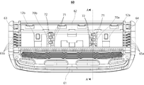
도 6a은 도 1b의 면도기 카트리지를 A-A' 방향으로 절취한 종단면도이다.
도 6b는 도 6a의 면도기 카트리지에서 일체형 블레이드를 강대날로 대체한 종단면도이다.
도 7은 도 1c의 면도기 카트리지를 B-B' 방향으로 절취한 횡단면도이다.
도 8a은 본 발명의 실시예에 따른 면도기를 면도기 핸들의 후면에서 바라본 사시도이고, 도 8b는 도 8a의 면도기 핸들로부터 면도기 카트리지 조립체를 분리한 사시도이다.
도 9a 및 도 9b는 면도기 카트리지의 저면에 커넥터를 결합하기 전에 양자의 위치 관계를 보여주기 위해, 각각 다른 방향으로 바라본 사시도들이다.
도 10a 내지 도 10d는 본 발명의 일 실시예에 따른 커넥터의 구조를 보다 자세히 설명하기 위한 도면들이다.
도 11은 본 발명의 일 실시예에 따른 면도기 카트리지 조립체의 저면도이다.
도 12a는 본 발명의 일 실시예에 따른 면도기의 분해 사시도, 도 12b는 도 12a의 분해 사시도의 측면도, 도 12c는 도 12a의 분해 사시도의 평면도이다.1A to 1D are a perspective view, a plan view, a front view and a bottom view, respectively, of a razor cartridge according to an embodiment of the present invention.
Figures 2a and 2b are side views of an integral blade and a pulley blade, respectively, according to an embodiment of the present invention.
FIGS. 3A and 3B are a perspective view and a plan view of a blade housing with the shaving blade, the lubrication band and the fixing clip removed in the razor cartridge of FIG. 1A;
Figs. 4A to 4D are a perspective view, a rear view, a right side view, and a plan view, respectively, of a terminal member located on the right side among two terminal members.
5 is a perspective view of a terminal member located on the left side of two terminal members.
FIG. 6A is a longitudinal sectional view of the razor cartridge of FIG. 1B taken in the direction AA '. FIG.
6B is a longitudinal sectional view in which the integral blade is replaced with a coiled blade in the razor cartridge of FIG. 6A.
FIG. 7 is a cross-sectional view of the razor cartridge of FIG. 1C taken in the direction BB '.
FIG. 8A is a perspective view of a razor according to an embodiment of the present invention, viewed from the rear of the razor handle, and FIG. 8B is a perspective view of the razor cartridge assembly removed from the razor handle of FIG. 8A.
Figs. 9A and 9B are perspective views viewed in different directions, respectively, in order to show the positional relationship between the two before the connector is coupled to the bottom surface of the razor cartridge.
10A to 10D are views for explaining the structure of the connector according to an embodiment of the present invention in more detail.
11 is a bottom view of a razor cartridge assembly according to an embodiment of the present invention.
FIG. 12A is an exploded perspective view of a razor according to an embodiment of the present invention, FIG. 12B is a side view of the exploded perspective view of FIG. 12A, and FIG. 12C is a plan view of an exploded perspective view of FIG.
본 발명의 이점 및 특징, 그리고 그것들을 달성하는 방법은 첨부되는 도면과 함께 상세하게 후술되어 있는 실시예들을 참조하면 명확해질 것이다. 그러나 본 발명은 이하에서 개시되는 실시예들에 한정되는 것이 아니라 서로 다른 다양한 형태로 구현될 것이며, 단지 본 실시예들은 본 발명의 개시가 완전하도록 하며, 본 발명이 속하는 기술분야에서 통상의 지식을 가진 자에게 발명의 범주를 완전하게 알려주기 위해 제공되는 것이며, 본 발명은 청구항의 범주에 의해 정의될 뿐이다. 명세서 전체에 걸쳐 동일 참조 부호는 동일 구성 요소를 지칭한다.BRIEF DESCRIPTION OF THE DRAWINGS The advantages and features of the present invention, and the manner of achieving them, will be apparent from and elucidated with reference to the embodiments described hereinafter in conjunction with the accompanying drawings. The present invention may, however, be embodied in many different forms and should not be construed as being limited to the embodiments set forth herein. Rather, these embodiments are provided so that this disclosure will be thorough and complete, and will fully convey the scope of the invention to those skilled in the art. Is provided to fully convey the scope of the invention to those skilled in the art, and the invention is only defined by the scope of the claims. Like reference numerals refer to like elements throughout the specification.
다른 정의가 없다면, 본 명세서에서 사용되는 모든 용어(기술 및 과학적 용어를 포함)는 본 발명이 속하는 기술분야에서 통상의 지식을 가진 자에게 공통적으로 이해될 수 있는 의미로 사용될 수 있을 것이다. 또 일반적으로 사용되는 사전에 정의되어 있는 용어들은 명백하게 특별히 정의되어 있지 않는 한 이상적으로 또는 과도하게 해석되지 않는다.Unless defined otherwise, all terms (including technical and scientific terms) used herein may be used in a sense commonly understood by one of ordinary skill in the art to which this invention belongs. Also, commonly used predefined terms are not ideally or excessively interpreted unless explicitly defined otherwise.
본 명세서에서 사용된 용어는 실시예들을 설명하기 위한 것이며 본 발명을 제한하고자 하는 것은 아니다. 본 명세서에서, 단수형은 문구에서 특별히 언급하지 않는 한 복수형도 포함한다. 명세서에서 사용되는 "포함한다(comprises)" 및/또는 "포함하는(comprising)"은 언급된 구성요소 외에 하나 이상의 다른 구성요소의 존재 또는 추가를 배제하지 않는다.The terminology used herein is for the purpose of illustrating embodiments and is not intended to be limiting of the present invention. In the present specification, the singular form includes plural forms unless otherwise specified in the specification. The terms " comprises "and / or" comprising "used in the specification do not exclude the presence or addition of one or more other elements in addition to the stated element.
이하 첨부된 도면들을 참조하여 본 발명의 일 실시예를 상세히 설명한다.Hereinafter, embodiments of the present invention will be described in detail with reference to the accompanying drawings.
도 1a는 본 발명의 일 실시예에 따른 면도기 카트리지(10)의 사시도, 도 1b는 면도기 카트리지(10)의 평면도, 도 1c는 면도기 카트리지(10)의 정면도, 도 1d는 면도기 카트리지(10)의 저면도이다. 면도기 카트리지(10)는 커팅 에지를 가진 적어도 하나의 면도 블레이드(5)와, 상기 적어도 하나의 면도 블레이드(5)를 수용하는 블레이드 하우징(60)과, 상기 블레이드 하우징(60)의 전측부(front portion, 61)에 배치되는 가드(1)와, 상기 블레이드 하우징의 후측부(rear portion, 62)에 배치되는 캡(3)을 포함하여 구성될 수 있다. 상기 가드 바(1)는 사용자의 모발을 면도 방향에 대해 대략 수직인 방향으로 기립시켜 면도 블레이드(5)의 절삭을 보다 용이하게 하며, 견고한 부재 또는 유연성이 있는 부재로 제조될 수 있다. 상기 캡(3)은 면도 스트로크시 최종적으로 피부로부터 이탈되는 접촉면으로서 윤활 밴드를 포함할 수 있다. 상기 윤활 밴드는 상기 절삭 이후 거칠어진 피부를 매끄럽게 정리해 주는 역할을 한다.1B is a plan view of the
면도 블레이드(5)는 일단부에 커팅 에지를 구비하며, 타단부가 블레이드 하우징(60)에 구비된 종단 부재(도 3b의 70a, 70b)에 안착될 수 있다. 이 때, 면도 블레이드(5)는 하나 또는 둘 이상의 개수로 배치될 수 있으며, 면도 블레이드(5)가 블레이드 하우징(60)에 수용되는 방향은 통상의 면도 방향에 수직인 횡방향이다. 이러한 면도 블레이드(5)는 스텐레스 스틸, 세라믹, 기타 다양한 금속 소재로 형성될 수 있으며, 일체로 절곡 공정을 통해 형성되는 일체형 블레이드나, 절곡된 서포트 상에 블레이드 에지부를 부착하여 형성되는 강대날 등으로 형성될 수 있다.The
도 2a는 일체형 블레이드(51)의 일 실시예를, 도 2b는 강대날의 일 실시예를 도시한 측면도이다. 도 2a를 참조하면, 일체형 블레이드(51)는 종단 부재(도 3b의 70a, 70b)에 안착되는 기저부(44), 전단측에 커팅 에지(41)를 구비하는 커팅부(42), 및 기저부(44)와 커팅부(42)를 연결하며 전방으로 굴곡된 절곡부(43)를 포함하여 구성될 수 있다. 이러한 일체형 블레이드(51)는 단일의 몸체로 절곡 공정에 의해 제작될 수 있으며 상대적으로 좁은 스팬 및 얇은 블레이드 두께를 가지도록 설계될 수 있다.FIG. 2A is an embodiment of an
또한, 도 2b에 도시된 바와 같이, 강대날(52)은 종단 부재(도 3b의 70a, 70b)에 안착되며 상대적으로 두껍게 형성되는 메탈 서포트(40)와, 메탈 서포트(40) 상에서 접합되고 커팅 에지(46)를 구비하는 커팅부(45)를 포함하여 2개의 부재로 구성된다. 상기 메탈 서포트(40)는 일체형 블레이드(51)와 마찬가지로 기저부(49)와 절곡부(48)를 구비하며, 커팅부(45)를 지지하고 접합하기 위한 블레이드 부착부(47)를 구비한다. 이러한 강대날(52)의 메탈 서포트(40)는 커팅부(45)에 비해 두껍게 형성되어 커팅부(45)를 견고하게 지지할 수 있다.2B, the
이와 같이, 면도 블레이드(5)는 일반적으로 전술한 일체형 블레이드(51) 또는 강대날(52)로 구성될 수 있지만, 이에 한하는 것은 아니고 면도 기능을 갖는 블레이드라면 기타 일자형이나 다른 형태를 배제하지 않는다.As such, the
한편, 면도 블레이드(5)가 블레이드 하우징(60)으로부터 이탈되지 않도록 하기 위하여, 면도 블레이드(5)의 상기 커팅 에지의 양측 단부를 상기 블레이드 하우징(60)에 고정하는 한 쌍의 고정 클립(7a, 7b)이 구비될 수 있다. 상기 한 쌍의 고정 클립(7a, 7b)은 면도 블레이드(5)의 상기 양측 단부를 감싸면서, 블레이드 하우징(60)의 양측 단부 근처에 형성된 적어도 하나의 관통 홀을 관통하여 블레이드 하우징(60)의 저면(11)에서 절곡된다. 도 1a 내지 도 1d에서는 일 실시예로서, 고정 클립(7a, 7b)이 블레이드 하우징(60)의 전단 부근에 형성된 관통홀을 관통하면서 블레이드 하우징(60)의 후단을 둘러싸는 형태(rear wrap-around type)로 되어 있다.On the other hand, a pair of fixing
도 1d에 도시된 면도기 카트리지(10)의 저면도를 참조하면, 블레이드 하우징(60)은 상기 저면(11)에서 횡방항에 수직인 종방향으로 상기 블레이드 하우징(60)를 지지하는 리브(rib)(12a, 12b)를 포함할 수 있다. 상기 리브(12a, 12b)는 면도 블레이드(5)를 가로지르는 방향으로 블레이드 하우징(60)을 보강하는 구조물이다. 상기 리브(12a, 12b)는 좌우측으로 한 쌍이 배치될 수 있지만 이에 한하지 않고 보다 많은 수가 배치될 수도 있다. 상기 리브(12a, 12b)에는 커넥터(20)가 용이하게 체결되도록 가이드하기 위한 가이드면(14a, 14b)이 구비된다. 블레이드 하우징(60)의 저면(11)에서, 가이드면(14a, 14b)은 리브(12a, 12b)의 깊이 방향으로 갈수록 횡방향으로 확장되도록 경사져 있다.Referring to the bottom view of the
또한, 블레이드 하우징(60)의 저면(11)에서 대략 면도 블레이드(5)와 캡(3) 사이에는 제1 횡방향 빔(18)이 형성되어 있으며, 상기 횡방향 빔(18)에는 커넥터(20)의 탄성 후크(도 9a의 23)와 체결되는 후크 결합부(15)가 구비되어 있다. 그리고, 블레이드 하우징(60)의 저면(11)에서 대략 가드 바(1)와 면도 블레이드(5) 사이에는 제2 횡방향 빔(19)이 형성되어 있으며, 상기 횡방향 빔(19)에는 면도기 핸들(30)의 플런저(미도시 됨)가 돌출할 때 접촉하면서 푸시되는 중앙 바(17)가 구비되어 있다. 상기 중앙 바(17)가 상기 플런저에 의해 푸시될 때 상기 중앙 바(17)는 상기 플런저와 반대 방향으로 어느 정도 탄성 변형될 수 있다.A first
한편, 블레이드 하우징(60)에는 상기 리브(12a, 12b)와 별도로 또는 상기 리브(12a, 12b)를 대체하여, 상기 블레이드 하우징(60)을 면도 블레이드(5)가 배치된 방향(횡방향)과 수직인 방향, 즉 종방향으로 연결하면서 지지하는 적어도 하나의 종단 부재(70a, 70b)가 구비될 수 있다.The
도 3a 및 도 3b는 도 1a의 면도기 카트리지(10)에서 면도 블레이드(5), 윤활 밴드(3) 및 고정 클립(7a, 7b)을 제거한 블레이드 하우징(10)의 사시도 및 평면도이다. 여기서 가드 바(1)는 블레이드 하우징(10)에 일체로 형성된 것으로 예시되어 있으나, 이에 한하지 않고 가드 바(1)는 블레이드 하우징(10)과 별물로 블레이드 하우징(10)에 탑재 또는 조립될 수도 있음은 물론이다. 이와 같이 가드 바(1)가 별물로 형성되는 경우에는 블레이드 하우징(10)은 도 3a에서 가드 바(1)를 제외한 부분으로 이해될 수 있다.3A and 3B are a perspective view and a plan view of the
도 3a 및 도 3b에 도시된 바와 같이, 블레이드 하우징(10)은 기본적으로, 전측부(61), 상기 전측부(61)와 대향하여 형성된 후측부(62), 상기 전측부(61)와 후측부(62)를 연결하는 좌측부(63) 및 우측부(64)를 포함하는 사각형 프레임 구조로 이해될 수 있다. 또한, 블레이드 하우징(60)은 상기 면도 블레이드(5)가 배치된 방향과 수직인 방향으로 상기 블레이드 하우징(60)을 연결하면서 지지하는 적어도 하나의 종단 부재(70a, 70b)를 포함한다. 일 실시예에 있어서, 상기 종단 부재(70a, 70b)는 상기 블레이드 하우징(60)의 전측부(61)와 후측부(62)를, 상기 종방향으로 연결한다.3A and 3B, the
도 3b에서는 2개의 종단 부재(70a, 70b)가 사용되는 것으로 도시되어 있으나, 이에 한하지 않고 종단 부재의 개수는 면도 블레이드(5)를 안착하기에 적합한 수로 적어도 하나 이상 배치될 수 있다.In FIG. 3B, two
이러한 종단 부재(70a, 70b) 상에는 상기 적어도 하나의 면도 블레이드(5)를 안착하기 위한 복수의 안착 돌기들(71, 72)이 종방향으로 배치되어 있다. 이러한 종단 부재(70a, 70b)와는 별도로 종방향으로 블레이드 하우징(60)을 보강하는 적어도 하나의 리브(12a, 12b)가 더 구비될 수 있다. 다만, 이에 한하지 않고 리브(12a, 12b)는 생략되거나 종단 부재(70a, 70b)와 일체로 형성될 수도 있다.A plurality of mounting
상기 복수의 안착 돌기(71, 72)는, 상기 블레이드 하우징(60)의 상방(도 3b의 도면에 수직이고 면도기 핸들 측의 반대 방향)으로 제1 높이(도 4c의 h1)를 갖는 제1 안착 돌기(71)와 상기 제1 높이보다 낮은 제2 높이(도 4c의 h2)를 갖는 제2 안착 돌기(72)를 포함한다. 이 때, 상기 제1 안착 돌기(71)와 상기 제2 안착 돌기(72)는 상기 종단 부재(70a, 70b) 상에서 종방향을 따라 나란하게 배치될 수 있다. 또한, 상기 제1 안착 돌기(71)와 상기 제2 안착 돌기(72)는 상기 종단 부재(70a, 70b) 상에서 상호 교대로 배치되는 것이 바람직하다.The plurality of
또한, 블레이드 하우징(60)의 우측부(64) 및 좌측부(63)에는 각각, 복수의 가압 돌기들(65a, 65b)이 형성될 수 있다. 이러한 가압 돌기들(65a, 65b)은 통상 핑거부로 불리기도 하며, 내부에 형성된 단차 구조로 인해 면도 블레이드(5)를 종방향으로 가압한다. 이러한 가압에 의해 면도 블레이드(5)가 블레이드 하우징(60)에 안착되었을 때 종방향으로 유격이 발생하지 않게 된다.A plurality of
복수의 면도 블레이드(5)는 제1 안착 돌기(71)와 제2 안착 돌기(72) 사이의 갭에 의해 형성되는 안착 슬롯에 삽입됨과 동시에 상기 가압 돌기들(65a, 65b) 사이에도 삽입된다. 따라서, 도 3b와 같은 실시예에서 하나의 면도 블레이드(5)는 총 4개의 위치에서 지지될 수 있다.The plurality of
도 4a 내지 도 4d는 각각, 2개의 종단 부재(70a, 70b) 중에서 우측에 위치하는 종단 부재(70a)의 사시도, 후면도, 우측면도 및 평면도이다. 먼저, 도 4a 내지 도 4c를 참조하면, 제1 안착 돌기(71)와 제2 안착 돌기(72)는 상기 종단 부재(70a) 상에서 종방향을 따라 나란하게 배치되어 있다. 특히, 상기 제1 안착 돌기(71)와 상기 제2 안착 돌기(72)는 상기 종단 부재(70a) 상에서 교대로 배치되어 있다.4A to 4D are a perspective view, a rear view, a right side view, and a plan view, respectively, of the
구체적으로, 제1 안착 돌기(71)는 기본적으로 전면(711), 후면(712) 및 상면(713)으로 구성되며, 상기 상면(713) 및 측면을 걸쳐 제1 그루브(715)가 형성되어 있다. 이 때, 상기 제1 그루브(715)는 제1 안착 돌기(71)의 상면(713)의 코너 중에서 상기 블레이드 하우징(60)의 외측을 향하는 코너에 형성된다. 또한, 제1 안착 돌기(71)의 상면(713)으로부터 후면(712) 쪽으로 경사면(714)이 형성되어 있다. Specifically, the
이러한 경사면(714)은 면도 블레이드(5)의 절곡부(도 6a의 43)의 내면과 유사한 형상으로 접촉하면서 상기 면도 블레이드(5)를 지지하기 위한 요소로서, 예를 들어 소정의 곡률을 갖는 라운드(round) 형상일 수 있다. 따라서, 이러한 경사면(714)은 후술하는 도 6a와 같이 일체형 블레이드의 전면의 적어도 일부를 지지할 수 있다. 예컨대, 도 2a와 같은 일체형 블레이드(51)의 전면 중에서, 커팅부(42) 또는 절곡부(43)의 적어도 하나의 지점이 제1 안착 돌기(71)의 경사면(714)에 의해 지지되거나, 또는 제1 안착 돌기(71) 상면(713)에 의해 지지될 수 있다.This
마찬가지로, 도 2b와 같은 강대날(52)의 전면 중에서, 블레이드 부착부(47) 또는 절곡부(48)의 적어도 하나의 지점이 제1 안착 돌기(71)의 경사면(714)에 의해 지지되거나, 제1 안착 돌기(71)의 상면(713)에 의해 지지될 수 있다.2B, at least one point of the
한편, 제2 안착 돌기(72)는 기본적으로 전면(721), 후면(722) 및 상면(723)으로 구성되며, 상기 상면(723) 및 측면을 걸쳐 제2 그루브(725)가 형성되어 있다. 이 때, 상기 제2 그루브(725)는 제2 안착 돌기(72)의 상면(723)의 코너 중에서 상기 블레이드 하우징(60)의 외측을 향하는 코너에 형성된다. 또한, 제2 안착 돌기(72)는 상면으로 갈수록 테이퍼 진 형상을 갖도록 테이퍼면(724)을 갖는다. 이러한 테이퍼면(724)은 제1 안착 돌기(71)와 제2 안착 돌기(72) 사이에 면도 블레이드(5)를 삽입할 때 삽입 위치에 다소간의 오차가 있더라도 정위치에 삽입되도록 해주는 요소이다.The
이러한 제1 안착 돌기(71)의 제1 그루브(715)의 프로파일과 제2 안착 돌기(72)의 제2 그루브(725)의 프로파일은 종방향을 따라 일치하게 하는 것이 바람직하다. 다만, 이에 한하지 않고 제1 그루브(715)의 프로파일과 제2 그루브(725)의 프로파일이 상이하도록 형성할 수도 있다. 예를 들어 전자가 후자보다 크거나 작도록, 또는 전자와 후자의 프로파일의 서로 다른 형상을 갖도록 할 수도 있을 것이다.It is preferable that the profile of the
뿐만 아니라, 제1 안착 돌기(71)에만 그루브(715)를 형성하고, 제2 안착 돌기(72)에는 그루브(725)를 형성하지 않을 수도 있다. 제2 안착 돌기(72)는 제1 안착 돌기(71)보다 크기가 작기 때문에, 제2 안착 돌기(72)에는 그루브(725)를 형성하지 않더라도 사출 성형 공정에서 성형물 취출시 불량 문제가 발생할 여지가 적기 때문이다.In addition, the
일 실시예에 따르면, 도 4a에 도시된 바와 같이 제1 안착 돌기(71)의 제1 그루브의 중심 및 제2 안착 돌기(72)의 제2 그루브의 중심은 종방향 가상선(La)을 따라 나란하게 정렬되어 있다. 이 때, 상기 제1 그루브(715)의 사이즈는 상기 제2 그루브(725)의 사이즈보다 크다.According to one embodiment, the center of the first groove of the
도 4a의 종단 부재(70a)의 후면도를 도시한 도 4b를 참조하면, 제2 돌기(72)의 제2 그루브(725)와 제1 돌기(71)의 제1 그루브(715)의 프로파일은 일치하고 있음을 알 수 있다. 이 때, 제2 그루브(725)의 중심과 제1 그루브(715)의 중심도 상기 가상선(La)와 나란하게 일치하고 있다. 이와 같이 제1 그루브(715)의 프로파일과 제2 그루브(725)의 프로파일이 일치되게 형성한 것은 사출 성형시 성형물을 용이하게 취출하기 위함이다. 이러한 그루브들(715, 725)은 종단 부재(70a, 70b)를 제작할 때 사출 성형 후 성형물을 취출하기 위한 언더컷(undercut)으로 기능한다. 이러한 언더컷의 위치는 상기 종방향을 따라 일치하도록 하는 것이 바람직하다.The profile of the
도 4a의 종단 부재(70a)의 우측면도 및 평면도를 각각 도시하는 도 4c 및 도 4d를 참조하면, 제1 안착 돌기(71)의 높이(h1)보다 제2 안착 돌기(72)의 높이(h2)가 낮다. 또한, 제1 안착 돌기(71)의 너비(w1)보다 제2 안착 돌기(72)의 너비(w2)가 좁다. 상기 h1은 대략 1.5~3mm 정도이고, 상기 h2는 상기 h1에 비해 대략 50~70%의 높이를 갖는다. 또한, 상기 w1은 대략 h1과 유사한 크기를 가질 수 있으며, w2는 상기 w1에 비해 대략 45~65%의 너비를 갖는다. 결국, 전체적으로 제1 안착 돌기(71)의 크기가 제2 안착 돌기(72)보다 크며, 이와 같이 상대적으로 큰 제1 안착 돌기(71)와 상대적으로 작은 제2 안착 돌기(72)를 교대로 배치하여 사출 성형시 충분한 클리어런스를 확보함으로써, 매우 협소하고 깊은 홈을 갖는 사출물을 제작할 때 발생하는 사출 불량의 문제를 상당히 해소할 수 있다.4C and 4D showing the right side view and the plan view of the
도 5는 2개의 종단 부재(70a, 70b) 중에서 좌측에 위치하는 종단 부재(70b)의 사시도이다. 우측 종단 부재(70a)와 마찬가지로 좌측 종단 부재(70b)에는 제1 안착 돌기(71)와 제2 안착 돌기(72)가 종방향을 따라 나란하게 교대로 배치되어 있다. 다만, 도 4a의 종단 부재(70a)에서는 2개의 제1 안착 돌기(71)와 3개의 제2 안착 돌기(72)가 교대로 배치되어 있음에 비해, 도 5의 종단 부재(70b)에서는 3개의 제1 안착 돌기(71)와 2개의 안착 돌기(72)가 교대로 배치되어 있다. 따라서, 대응하는 종방향 위치에서 종단 부재(70a, 70b) 상에 위치하는 안착부재(71, 72)는 서로 다른 종류가 배치되어 있다. 즉, 제1 안착 돌기(71)와 제2 안착 돌기(72)는 상기 좌측 종단 부재(70b) 상에서 제1 순서로 교대로 배치되고, 제1 안착 돌기(71)와 제2 안착 돌기(72)는 상기 우측 종단 부재(70a) 상에서 제2 순서로 교대로 배치되는데, 상기 제1 순서와 상기 제2 순서는 서로 반대이다. 이와 같은 배치는 면도 블레이드(5)의 전면(또는 후면)이 2개의 종단 부재들(70a, 70b) 중에서 적어도 하나의 지점에서 상기 제1 안착 돌기(71)에 의해 지지되게 하기 위함이다.5 is a perspective view of a
도 6a는 도 1b의 면도기 카트리지(10)를 A-A' 방향으로 절취한 종단면도이다. 도 1b에서는 안착된 면도 블레이드(5)로 인하여 블레이드 하우징(60)에서 절취된 위치가 분명하게 파악되기 어려우므로, 도 3b의 블레이드 하우징(60)에도 상기 A-A'의 위치를 참고로 표기하였다.6A is a longitudinal sectional view taken along the line A-A 'of the
도 6a를 참조하면, 도시된 5개의 면도 블레이드(5a 내지 5e)는 좌측 종단 부재(70b)에 교대로 배치된 제1 안착 돌기(71)와 제2 안착 돌기(72)의 사이의 갭(안착 슬롯)에 삽입되어 있다. 여기서, 도시된 제1 안착 돌기들(71) 중에서 빗금으로 표시된 제1 안착 돌기들(71)은 좌측 종단 부재(70b)에 형성된 것이고, 빗금이 없는 제1 안착 돌기들(71)은 우측 종단 부재(70a)에 형성된 것이다. 우측 종단 부재(70a) 상에 형성된 제2 안착 돌기들은 빗금으로 표시된 제1 안착 돌기들(71)에 가려지므로 도시되지 않았다.6A, the five
도 6a에 예시된 바와 같이, 5개의 면도 블레이드(5a 내지 5e) 각각의 전면 중에서 적어도 일부가 하나의 제1 안착 돌기(71)에 의해 지지되고 있음을 알 수 있다. 여기서 면도 블레이드(5a 내지 5e)는 도 2a와 같은 일체형 블레이드(51)로 예시되어 있다.As illustrated in Fig. 6A, it can be seen that at least a part of the front surface of each of the five
구체적으로, 면도 블레이드(5a 내지 5e) 각각이 커팅부(42), 절곡부(43) 및 기저부(44)로 구성된다고 할 때, 면도 블레이드(5a 내지 5e)의 전면 중에서 커팅부(42) 및 절곡부(43)의 일부가 상기 제1 안착 돌기(71)의 상면(713) 또는 경사면(714)에 의해 지지될 수 있다. 또한, 기저부(44)는 제1 안착 돌기(71) 및 제2 안착 돌기(72) 사이의 갭(안착 슬롯) 내에 삽입되면서 제1 안착 돌기(71) 및 제2 안착 돌기(72) 사이에서 지지될 수 있다. 실제로는, 면도 블레이드(5a 내지 5e)를 실제로 종단 부재(70a, 70b)에 안착하는 다양한 실시예에 따라, 면도 블레이드(5a 내지 5e)의 커팅 에지를 제외한 임의의 지점들이 제1 및 제2 안착 돌기(72)에 의해 지지될 수 있을 것이다.Specifically, it is assumed that each of the
한편, 도 6a의 면도 블레이드(5a 내지 5e)를 일체형 블레이드(51) 대신에 강대날(52)로 구현할 수도 있다. 도 6b는 블레이드 하우징(60)의 종단 부재(70a, 70b)에 강대날(52)이 안착되는 실시예를 보여준다.On the other hand, the
이 때, 면도 블레이드(5a 내지 5e) 각각은 커팅부(45)와 메탈 서포트(40)를 포함한 2개의 부재로 이루어질 수 있는데, 커팅부(45)는 전단부에 커팅 에지(46)가 형성되어 있고, 메탈 서포트(40)는 안착 슬롯에 삽입하기 위한 기저부(49), 커팅부(45)가 접합되는 블레이드 부착부(47) 및 양자를 연결하는 절곡부(48)를 포함한다.At this time, each of the
면도 블레이드(5a 내지 5e)가 종단 부재(70a, 70b)에 안착될 때, 면도 블레이드(5a 내지 5e)의 전면 중에서, 블레이드 부착부(47) 및 절곡부(48)의 일부가 상기 제1 안착 돌기(71)의 상면(713) 또는 경사면(714)에 의해 지지될 수 있다. 또한, 기저부(49)는 제1 안착 돌기(71) 및 제2 안착 돌기(72) 사이의 갭(안착 슬롯) 내에 삽입되면서 제1 안착 돌기(71) 및 제2 안착 돌기(72) 사이에서 지지될 수 있다. 따라서, 면도 블레이드(5a 내지 5e)를 실제로 종단 부재(70a, 70b)에 안착하는 다양한 실시예에 따라, 커팅부(45)를 제외한 메탈 서포트(40)의 임의의 지점들이 제1 및 제2 안착 돌기(72)에 의해 지지될 수 있다.When the
도 6a 및 도 6b에서 설명된 바와 같이, 면도 블레이드(5a 내지 5e)는 커팅 에지를 제외한 임의의 지점들에서 제1 안착 돌기(71)나 제2 안착 돌기(72)에 의해 고정되거나 지지될 수 있다. 다만, 면도 블레이드(5a 내지 5e)를 종단 부재(70a, 70b)에 안착할 때, 조립 특성으로 인하여 면도 블레이드(5a 내지 5e)와 제1 및 제2 안착 돌기(71, 72) 간에 반드시 면대면 접촉 및 지지가 이루어지는 것은 아니다. 이러한 조립 특성에 따르면, 면도 블레이드(5a 내지 5e)의 전면의 일부(예를 들어, 일체형 블레이드(51)의 경우 커팅부(42), 절곡부(43), 기저부(44), 또는 강대날(52)의 경우 블레이드 부착부(47), 절곡부(48), 기저부(49)의 일부)가 제1 안착 돌기(71)의 상면(713) 또는 경사면(714)에 의해 지지되면서, 면도 블레이드(5a 내지 5e)의 후면의 하단이 제2 안착 돌기(72)의 전면의 하단 부근에서 접촉하면서 지지될 수 있다. 즉, 면도 블레이드(5a 내지 5e)의 전면은 보다 높은 지점에서 제1 안착 돌기(71)에 의해 지지되고, 그 후면은 보다 낮은 지점에서 제2 안착 돌기(72)에 의해 지지될 수 있는 것이다.6A and 6B, the
따라서, 면도 블레이드(5a 내지 5e)가 일체형 블레이드(51)인지, 강대날(52)인지와 상관없이, 면도 블레이드(5a 내지 5e)의 전면 중에서 커팅 에지를 제외한 적어도 일부분이 제1 안착 돌기(71) 및 제2 안착 돌기(72)에 의해 확실하게 지지되기 때문에 면도시 면도 블레이드(5a 내지 5e)의 요동이나 변형의 문제를 방지할 수 있다.Therefore, at least a part of the front surface of the
또한, 종단 부재들(70a, 70b) 상에서, 면도 블레이드(5a 내지 5e)의 전면의 일부 및 후면의 일부는 제1 안착 돌기(71) 및 제2 안착 돌기(72)에 의해 각각 지지되거나, 반대로 제2 안착 돌기(72) 및 제1 안착 돌기(71)에 의해 각각 지지될 수 있다. 예를 들어, 제3 면도 블레이드(5c)는 제1 종단 부재(70a) 상에서는 그 전면의 일부가 제2 안착 돌기(72)의 후면(722)에 의해 지지되고, 그 후면의 일부가 제1 안착 돌기(71)의 전면(711)에 의해 지지된다. 반대로, 제3 면도 블레이드(5c)는 제2 종단 부재(70b) 상에서는 그 전면의 일부가 제1 안착 돌기(71)의 후면(712), 상면(713) 또는 경사면(714)에 의해 지지되고, 그 후면의 일부가 제2 안착 돌기(72)의 전면(721)에 의해 지지된다. 이와 같이 특정 면도 블레이드(5c)에 대한 안착 돌기(71, 72)의 엇갈림 지지 패턴은 다른 면도 블레이드들(5a, 5b, 5d, 5e)에 대해서도 마찬가지이다.Further, on the
이와 같이, 서로 다른 종단 부재(70a, 70b)에서 제1 안착 돌기(71) 및 제2 안착 돌기(72)들의 배치 순서를 상이하게(엇갈리게) 함에 의해, 특정 면도 블레이드(5a 내지 5e)를 기준으로 적어도 한 쪽의 종단 부재에서는 그 전면이 제1 안착 돌기(71)에 의해 견고하게 지지될 수 있게 할 수 있는 것이다.As described above, by arranging the placement order of the
도 7은 도 1c의 면도기 카트리지(10)를 B-B' 방향으로 절취한 횡단면도이다. 7 is a cross-sectional view of the
전술한 바와 같이, 면도 블레이드(5a 내지 5e)는 제1 및 제2 안착돌기(71, 72) 사이에서 안정적으로 지지될 수 있다. 다만, 마지막 블레이드(5e)의 후면이 안착 돌기들(71, 72) 대신에 블레이드 하우징(60)의 후측벽(66)에 의해 바로 지지되게 할 수도 있다. 이러한 구성은, 마지막 블레이드(5e)의 후측 위치까지 안착 돌기(71, 72)를 배치하기 보다는, 상기 블레이드(5e)의 후면(내지 후면의 일부)이 후측벽(66) 또는 상기 후측벽(66)에서 전방으로 약간 돌출된 돌출부(67a, 67b)에 의해 직접 지지되도록 함으로써 블레이드 하우징(60)의 구조를 보다 간소화할 수 있기 때문이다.As described above, the
이러한 돌출부(67a, 67b)는 예를 들어, 도 7에 도시된 바와 같이 종단 부재(70a, 70b)가 후측벽(66)과 만나는 위치에 배치될 수 있으나, 이에 한하지 않고, 돌출부(67a, 67b)의 배치 위치와 개수는 필요에 따라 다양하게 선택될 수 있을 것이다.The
한편, 전체적으로 도 7을 살펴보면, 복수의 면도 블레이드(5a 내지 5e)는, 종단 부재(70a, 70b) 상에서는 제1 안착 돌기(71)와 제2 안착 돌기(72) 사이에서 지지되고, 블레이드 하우징(60)의 우측부(64) 및 좌측부(63)에서는 가압 돌기(65a, 65b)에 의해 지지되고 있다. 따라서, 면도 블레이드(5a 내지 5e) 각각은 횡방향으로 총 4개의 위치에서 지지될 수 있게 된다. 이상의 실시예에서는 블레이드 하우징(60)에 2개의 종단 부재(70a, 70b)가 배치되는 것으로 하여 설명하였으나 반드시 이에 한하는 것은 아니고, 제조의 용이성, 조립의 편의성, 면도 블레이드의 안착성 등을 고려하여, 1개의 종단 부재를 블레이드 하우징(60)의 횡방향 중앙에 배치하거나, 3이상의 종단 부재를 블레이드 하우징(60)에 배치할 수도 있을 것이다.7, a plurality of
또한, 도 7에서는 블레이드 하우징(60)의 우측부(64) 및 좌측부(63)에 형성된 가압 돌기들(65a, 65b)이 종단 부재(70a, 70b)에 배치된 안착 돌기들(71, 72)과 상이한 형태로 도시되어 있지만, 이에 한하지 않고 상기 가압 돌기들(65a, 65b)을 안착 돌기들(71, 72)로 대체할 수도 있다. 이 경우에는 종단 부재(70a, 70b), 우측부(64) 및 좌측부(63) 모두가 안착 돌기들(71, 72)에 의해 면도 블레이드(5a 내지 5e)를 지지하게 될 것이다.7, the
또한, 면도 블레이드의 개수도 다양하게 선택할 수 있을 것이나, 이러한 개수에 따라 제1 안착 돌기(71) 및 제2 안착 돌기(72)의 개수도 대응하여 가감될 것이다.Also, the number of the shaving blades may be variously selected, but the number of the
지금까지는, 본 발명의 일 실시예에 따른 면도기 카트리지(10)에 있어서, 면도 블레이드의 안착 성능을 높이면서도 사출 성형 등의 제조 공정에서 제조가 용이한 안착 돌기를 갖는 블레이드 하우징의 구조에 대해서 설명하였다. 이하에서는, 면도기 카트리지(10)와, 이러한 면도기 카트리지(10)를 면도기 핸들(30)에 착탈 가능하게 조립하기 위한 커넥터(20)를 포함하는 면도기 카트리지 조립체(50)에 대하여 상세히 설명할 것이다.Up to now, a structure of a blade housing having a seating protrusion that is easy to manufacture in a manufacturing process such as injection molding, while improving the seating performance of a shaving blade, has been described in the
도 8a는 본 발명의 실시예에 따른 면도기(100)를 면도기 핸들(30)의 후면(면도기 카트리지(10)의 저면이 보이는 쪽)에서 바라본 사시도이고, 도 8b는 도 8a의 면도기 핸들(30)로부터 면도기 카트리지 조립체(50)를 분리한 사시도이다.8A is a perspective view of the
상기 실시예에 따른 면도기(100)는 면도기 카트리지(10) 및 상기 면도기 카트리지(10)과 고정 결합되는 커넥터(20)를 포함하는 면도기 카트리지 조립체(50)와, 상기 면도기 카트리지 조립체(50)와 착탈 가능하게 결합되는 면도기 핸들(30)을 포함한다. 면도기 핸들(30)의 단부에는 한쌍의 플런저 가드(31)가 형성되어 있으며, 상기 플런저 가드(31)가 상기 면도기 카트리지 조립체(50)에 구비된 결합 공간에 삽입되거나 이탈될 수 있다. The
또한, 면도기 핸들(30)의 플런저 가드(31)를 상기 면도기 카트리지 조립체(50)로부터 제거할 때에는, 면도기 핸들(30)의 후면 상에 배치된 슬라이더 버튼(37)을 면도기 카트리지 조립체(50) 측으로 푸시(push)하면 된다. 이 때에는 한 쌍의 플런저 가드(31)의 사이에서 탄성 바이어스 하에 있는 플런저(미도시 됨)가 면도기 카트리지 조립체(50) 일측을 향해 돌출되면서 상기 일측을 푸시하고, 이에 따라 플런저 가드(31)가 면도기 카트리지 조립체(50)로부터 이탈된다.When the
한편, 플런저 가드(31)는 면도기 핸들(30)의 단부 근처에 형성된 회전축(ax)을 기준으로 일정 각도 범위 내에서 회동(swivel)할 수 있다. 이에 따라, 플런저 가드(31) 결합시에는 면도기 카트리지 조립체(50)도 함께 상기 회전축(ax)을 기준으로 회동할 수 있는 것이다.The
도 9a 및 도 9b는 면도기 카트리지(10)의 저면에 커넥터(20)를 결합하기 전에 양자의 위치 관계를 보여주기 위해, 각각 다른 방향으로 바라본 사시도들이다. 커넥터(20)가 면도기 카트리지(10)의 저면에 결합될 때, 이너 캔틸레버(21a, 21b) 및 이에 대향하는 아우터 캔틸레버(22a, 22b)의 조합(이하, 이너-아우터 캔틸레버라고 함)이 각각의 리브(12a, 12b)를 양측에서 협지한다. 이와 함께, 커넥터(20)에서 두 쌍의 이너-아우터 캔틸레버 사이에는 탄성 후크(23)가 형성되어, 면도기 카트리지(10)의 저면에서 한 쌍의 리브(12a, 12b) 사이에 형성된 후크 결합부(15)와 결합된다. 이 때, 탄성 후크(23)의 단부가 상기 후크 결합부(15)의 내측에 형성된 단차부(151)에 걸림과 동시에, 상기 이너-아우터 캔틸레버가 상기 리브(12a, 12b)를 양측에서 협지함으로써, 커넥터(20)와 면도기 카트리지(10) 간의 견고한 결합이 이루어진다.9A and 9B are perspective views viewed in different directions in order to show the positional relationship between the
도 10a 내지 도 10d는 본 발명의 일 실시예에 따른 커넥터(20)의 구조를 보다 자세히 설명하기 위한 도면들이다. 이 중에서 도 10a 및 도 10b는 커넥터(20)를 각각 다른 방향에서 바라본 사시도들이고 도 10c 및 도 10d는 각각 커넥터(20)의 평면도 및 저면도이다.10A to 10D are views for explaining the structure of the
커넥터(20)와 면도기 카트리지(10) 간의 조립시에는, 일단 커넥터(20)의 좌우측에 각각 형성된 이너-아우터 캔틸레버(21a, 22a 또는 21b, 22b)의 조합이, 면도기 카트리지(10)의 대응 위치에 형성된 리브(12a, 12b)를 협지하도록 체결된다. 이와 같은 체결만으로도 양자 간에 횡방향으로는 견고한 조립이 이루어질 수 있지만, 이에 수직인 종방향으로는 조립 공차로 인한 미소한 종방향 유격이 발생할 수 있다. 따라서, 본 발명의 일 실시예에 있어서, 커넥터(20)는 면도기 카트리지(10)의 후크 결합부(15)와 대응되는 위치에서 상기 후크 결합부(15)와 결합 가능한 탄성 후크(23)를 더 포함할 수 있다. 이 때, 캔틸레버 빔 구조로 벤딩될 수 있는 탄성 후크(23)의 단부가 상기 후크 결합부(15)의 내측에 형성된 단차부(151)에 걸림으로써 상기 종방향 유격이 효과적으로 해소될 수 있기 때문에, 커넥터(20)와 면도기 카트리지(10) 간의 한층 더 견고한 결합이 보장될 수 있다.When assembling the
또한, 커넥터(20)에는 상기 탄성 후크(23)의 주변에 형성되고, 상기 탄성 후크(23)와 상기 후크 결합부(15)가 정위치에서 결합될 수 있도록 상기 후크 결합부(15)를 가이드하기 위한 한쌍의 단턱부(24a, 24b)가 구비될 수 있다. 상기 단턱부(24a, 24b)는 탄성 후크(23)를 중심으로 좌우 대칭 형상을 가질 수 있으며, 두 단턱부(24a, 24b) 사이에는 상기 후크 결합부(15)가 가이드되면서 움직일 수 있는 공간인 가이드 슬롯(25)이 형성된다.The
한편, 상기 가이드 슬롯(25)의 반대쪽에는, 양자(10, 20)의 조립시 면도기 카트리지(10)의 중앙 바(17)와 소정의 유격(y)을 두고 위치하는 유격 홈(26)이 형성되어 있다. 면도기 핸들(30)의 플런저(미도시 됨)가 돌출할 때 중앙 바(17)는 상기 플런저와 반대 방향으로 어느 정도 탄성 변형되면서 푸시된다. 이 때, 유격 홈(26)은 상기 푸시되는 중앙 바(17)가 약간의 탄성을 가지면서 종방향으로 벤딩될 수 있는 공간을 제공한다.On the other hand, on the opposite side of the
한편 도 10d를 참조하면, 커넥터(20)의 내측면에는 대략 원호(arc) 형상을 갖는 리세스부(27)가 형성되어 있다. 상기 리세스부(27)는 면도기 핸들(30)의 근위 단부에 형성된 한쌍의 플런저 가드(도 12a 내지 도 12c의 31)의 외형과 정합되는 프로파일을 갖는다.On the other hand, referring to FIG. 10D, a
도 11은 커넥터(20)와 면도기 카트리지(10)의 조립체, 즉 면도기 카트리지 조립체(50)의 저면도이다. 11 is a bottom view of the assembly of
이와 같이 면도기 카트리지(10)과 상기 커넥터(20)가 조립된 상태에서, 상기 면도기 카트리지(10)과 상기 커넥터(20) 사이에는 상기 면도기 카트리지(10)의 전단부 방향으로 면도기 핸들(30)의 근위 단부가 삽입될 수 있는 체결 공간(55)이 형성된다. 이 때, 이너 캔틸레버(21a, 21b)는 상기 횡방향(d)으로 상기 체결 공간(55)의 양측 단부를 형성한다. 또한, 면도기 카트리지(10)의 중앙 바(17)에 의해 상기 체결 공간(55)은 2개의 영역으로 구분되며, 상기 구분된 2개의 영역에 한쌍의 상기 플런저 가드(31)가 각각 삽입될 수 있다.The
이와 같은 조립 상태에서 면도기 핸들(30)을 상기 어셈블리(50)로부터 이탈시킬 때에는, 사용자의 조작에 의해 면도기 핸들(30)의 플런저(미도시 됨)가 돌출된다. 따라서, 상기 플런저가 중앙 바(17)를 푸시하면서 상기 한쌍의 플런저 가드(31)가 상기 체결 공간(55)으로부터 후퇴하여 이탈하게 된다. 이 때, 상기 플런저에 의해 푸시되는 중앙 바(17)는 약간의 탄성을 가지면서 종방향으로 소정의 유격(y) 범위 내에서 벤딩될 수 있다.When releasing the razor handle 30 from the
도 12a는 본 발명의 일 실시예에 따른 면도기(100)의 분해 사시도, 도 12b는 도 12a의 분해 사시도의 측면도, 도 12c는 도 12a의 분해 사시도의 평면도이다.FIG. 12A is an exploded perspective view of the
전술한 바와 같이 면도기 카트리지(10)과 커넥터(20)가 면도기 카트리지 조립체(50)로 조립된 후에는, 면도기 카트리지 조립체(50)에 형성되는 체결 공간(55)에 한쌍의 플런저 가드(31)가 착탈 가능하게 결합될 수 있다. 이러한 체결 공간(55)은 중앙 바(17)에 의해 2개의 영역으로 구분될 수 있고, 이러한 구분된 영역 한쌍의 상기 플런저 가드(31)가 각각 삽입될 수 있다. 즉, 한쌍의 플런저 가드(31)가 체결 공간(55)에 삽입될 때, 중앙 바(17)가 상기 한쌍의 플런저 가드(31)의 사이의 공간을 지지한다.After the
상기 플런저 가드(31)는 핸들 그립(39)과 결합 가능하게 별도로 구비되는 카트리지 마운터(35)의 근위 단부 측에 구비될 수 있으며, 면도기의 횡방향(d)과 평행한 회전축(ax)을 기준으로 소정의 각도 범위 내에서 회동할 수 있다. 따라서, 면도 진행중에 플런저 가드(31)와 결합된 면도기 카트리지 조립체(50)도 사용자의 조작에 따라 상기 회전축(ax)을 기준으로 회동될 수 있다. 상기 카트리지 마운터(35)의 원위 단부 측에는 결합 부재(33)가 형성되어 있어서 핸들 그립(39)의 근위 단부와 체결될 수 있도록 되어 있다. 물론 이와 달리, 카트리지 마운터(35)를 별도의 구성요소로 제작하여 핸들 그립(39)과 결합하는 대신에 핸들 그립(39)과 일체로 형성할 수도 있을 것이다.The
한편, 카트리지 마운터(35)의 일측에는 슬라이더 버튼(37)이 형성되어 있는데, 사용자는 이러한 슬라이더 버튼(37)을 면도기 카트리지 조립체(50) 측으로 밀어 올림으로써 상기 플런저(미도시 됨)가 돌출되도록 할 수 있다. 도 12a에 도시된 바와 같이, 카트리지 마운터(35)의 근위 단부에는 한 쌍의 플런저 가드(31)가 구비되고, 상기 한 쌍의 플런저 가드(31) 사이에는 플런저가 출납 가능하게 형성되어 있다. 이 때, 상기 플런저는 외력이 없을 때에는 외부로 돌출되지 않는 위치에 있다가, 사용자가 슬라이더 버튼(37)을 면도기 카트리지 조립체(50) 쪽으로 밀어 올리면 상기 플런저는 두 플런저 가드(31) 사이에서 면도기 카트리지 조립체(50) 측으로 돌출된다. 이와 같이 돌출된 플런저는 상기 중앙 바(도 9b의 17)를 푸시함으로써 체결 공간(55)에 결합되어 있던 플런저 가드(31)가 면도기 카트리지(50)로부터 이탈된다.On the other hand, a
이상 첨부된 도면을 참조하여 본 발명의 실시예를 설명하였지만, 본 발명이 속하는 기술분야에서 통상의 지식을 가진 자는 본 발명이 그 기술적 사상이나 필수적인 특징을 변경하지 않고서 다른 구체적인 형태로 실시될 수 있다는 것을 이해할 수 있을 것이다. 그러므로 이상에서 기술한 실시예들은 모든 면에서 예시적인 것이며 한정적이 아닌 것으로 이해해야 한다.While the present invention has been described in connection with what is presently considered to be practical exemplary embodiments, it is to be understood that the invention is not limited to the disclosed embodiments, but, on the contrary, You will understand. It is therefore to be understood that the embodiments described above are in all respects illustrative and not restrictive.
Claims (21)
상기 적어도 하나의 면도 블레이드를 수용하는 블레이드 하우징;
상기 블레이드 하우징의 전측부(front portion)에 배치되는 가드; 및
상기 블레이드 하우징의 후측부(rear portion)에 배치되는 캡을 포함하는 면도기 카트리지로서,
상기 블레이드 하우징은, 상기 적어도 하나의 면도 블레이드가 수용되는 횡방향과 수직인 종방향으로 상기 전측부와 상기 후측부를 연결하는 적어도 하나의 종단 부재를 포함하고,
상기 종단 부재 상에는 복수의 안착 돌기들이 상기 종방향으로 배치되어, 상기 복수의 안착 돌기들 사이로 상기 적어도 하나의 면도 블레이드를 안착하며,
상기 복수의 안착 돌기는, 상기 블레이드 하우징의 상방으로 제1 높이를 갖는 제1 안착 돌기와 상기 제1 높이보다 낮은 제2 높이를 갖는 제2 안착 돌기를 포함하고,
상기 적어도 하나의 면도 블레이드는 서로 다른 높이를 가지는 상기 제1 안착 돌기와 상기 제2 안착 돌기 사이에 안착되는, 면도기 카트리지.At least one shaving blade having a cutting edge;
A blade housing receiving said at least one shaving blade;
A guard disposed at a front portion of the blade housing; And
A cap disposed on a rear portion of the blade housing,
Wherein the blade housing includes at least one longitudinal member connecting the front and rear portions in a longitudinal direction perpendicular to the transverse direction in which the at least one shaving blade is received,
Wherein a plurality of seating projections are longitudinally arranged on the longitudinal member to seat the at least one shaving blade between the plurality of seating projections,
Wherein the plurality of seating projections include a first seating projection having a first height above the blade housing and a second seating projection having a second height lower than the first height,
Wherein the at least one shaving blade is seated between the first and second seating projections having different heights.
상기 제1 안착 돌기와 상기 제2 안착 돌기는 상기 종단 부재 상에서 교대로 배치되는, 면도기 카트리지.The method according to claim 1,
Wherein the first and second mounting projections are alternately arranged on the longitudinal member.
상기 제1 안착 돌기는 상기 적어도 하나의 면도 블레이드가 안착된 방향으로 제1 너비를 가지며, 상기 제2 안착 돌기는 상기 제1 너비보다 좁은, 면도기 카트리지.3. The method of claim 2,
Wherein the first seating projection has a first width in a direction in which the at least one shaving blade is seated and the second seating projection is narrower than the first width.
상기 제1 안착 돌기와 상기 제2 안착 돌기는 상기 종단 부재 상에서 상기 종방향을 따라 나란하게 배치되는, 면도기 카트리지.5. The method of claim 4,
Wherein the first mounting projection and the second mounting projection are arranged on the longitudinal member along the longitudinal direction.
상기 제1 안착 돌기는 상면과 후면을 포함하고, 상기 상면 또는 상기 후면이 상기 적어도 하나의 면도 블레이드의 전면의 적어도 일부를 지지하는, 면도기 카트리지.3. The method of claim 2,
Wherein the first seating projection includes an upper surface and a rear surface and the upper surface or the rear surface supports at least a portion of a front surface of the at least one shaving blade.
상기 제1 안착 돌기는 상기 상면 및 상기 후면을 연결하는 경사면을 더 포함하고, 상기 경사면이 상기 적어도 하나의 면도 블레이드의 전면의 적어도 일부를 지지하는, 면도기 카트리지.The method according to claim 6,
Wherein the first mounting projection further comprises an inclined surface connecting the upper surface and the rear surface, the ramp supporting at least a portion of a front surface of the at least one shaving blade.
상기 제1 안착 돌기는 상면, 후면 및 상기 상면과 상기 후면을 연결하는 경사면을 더 포함하고,
상기 적어도 하나의 면도 블레이드는 커팅 에지를 갖는 커팅부, 기저부, 및 상기 커팅부와 상기 기저부를 연결하는 절곡부를 포함하는 일체형 블레이드이며,
제1 안착 돌기의 상기 상면 또는 상기 경사면이, 상기 커팅부의 전면 및 상기 절곡부의 전면 중에서 적어도 일부를 지지하는, 면도기 카트리지.3. The method of claim 2,
Wherein the first mounting projection further comprises an upper surface, a rear surface, and an inclined surface connecting the upper surface and the rear surface,
Wherein the at least one shaving blade is a unitary blade including a cutting portion having a cutting edge, a base portion, and a bend connecting the cutting portion and the base portion,
Wherein the upper surface or the inclined surface of the first mounting projection supports at least a part of the front surface of the cutting portion and the front surface of the bent portion.
상기 제1 안착 돌기는 상면, 후면 및 상기 상면과 상기 후면을 연결하는 경사면을 더 포함하고,
상기 적어도 하나의 면도 블레이드는, 커팅 에지를 갖는 커팅부와, 상기 커팅부와 접합되어 상기 커팅부를 지지하는 메탈 서포트를 포함하는 강대날이며,
상기 메탈 서포트는 기저부, 상기 커팅부와 접합되는 블레이드 부착부, 및 상기 기저부와 상기 블레이드 부착부를 연결하는 절곡부를 포함하고,
제1 안착 돌기의 상기 상면 또는 상기 경사면이, 상기 블레이드 부착부의 전면 및 상기 절곡부의 전면 중에서 적어도 일부를 지지하는, 면도기 카트리지.3. The method of claim 2,
Wherein the first mounting projection further comprises an upper surface, a rear surface, and an inclined surface connecting the upper surface and the rear surface,
Wherein the at least one shaving blade comprises a cutting portion having a cutting edge and a metal support joined to the cutting portion to support the cutting portion,
Wherein the metal support includes a base portion, a blade attachment portion joined to the cutting portion, and a bending portion connecting the base portion and the blade attachment portion,
Wherein the upper surface or the inclined surface of the first mounting projection supports at least a part of the front surface of the blade attaching portion and the front surface of the bent portion.
상기 제2 안착 돌기의 상부에는 테이퍼면이 형성되어, 상기 적어도 하나의 면도 블레이드의 삽입을 용이하게 하는, 면도기 카트리지.6. The method of claim 5,
Wherein a tapered surface is formed on the upper portion of the second seating projection to facilitate insertion of the at least one shaving blade.
상기 제1 안착 돌기의 상단부의 코너에는 제1 그루브(groove)가 형성되는, 면도기 카트리지.6. The method of claim 5,
And a first groove is formed at the corner of the upper end of the first mounting projection.
상기 제2 안착 돌기의 상단부의 코너에는 제2 그루브가 형성되는, 면도기 카트리지.12. The method of claim 11,
And a second groove is formed at the corner of the upper end of the second mounting projection.
상기 제1 및 제2 그루브의 프로파일은 상기 종방향을 따라 일치하는, 면도기 카트리지.13. The method of claim 12,
Wherein profiles of the first and second grooves conform along the longitudinal direction.
상기 제1 그루브는 상기 제1 안착 돌기의 상단부의 코너 중에서 상기 블레이드 하우징의 외측을 향하는 코너에 형성되고,
상기 제2 그루브는 상기 제2 안착 돌기의 상단부의 코너 중에서 상기 블레이드 하우징의 외측을 향하는 코너에 형성되는, 면도기 카트리지.13. The method of claim 12,
The first groove is formed at a corner of the corner of the upper end of the first seating projection toward the outside of the blade housing,
And the second groove is formed at a corner of the corner of the upper end of the second seating projection toward the outside of the blade housing.
상기 적어도 하나의 종단 부재는, 상기 블레이드 하우징의 좌측에서 상기 블레이드 하우징을 지지하는 좌측 종단 부재와, 상기 블레이드 하우징의 우측에서 상기 블레이드 하우징을 지지하는 우측 종단 부재를 포함하고,
상기 제1 안착 돌기 및 상기 제2 안착 돌기를 포함하는 상기 복수의 안착 돌기가 상기 좌측 종단 부재와, 상기 우측 종단 부재 상에 모두 배치되는, 면도기 카트리지.The method according to claim 1,
Wherein the at least one termination member includes a left termination member for supporting the blade housing at a left side of the blade housing and a right side end member for supporting the blade housing at a right side of the blade housing,
Wherein the plurality of mounting projections including the first mounting projection and the second mounting projection are both disposed on the left longitudinal member and the right longitudinal member.
상기 제1 안착 돌기와 상기 제2 안착 돌기는 상기 좌측 종단 부재 상에서 제1 순서로 교대로 배치되고, 상기 제1 안착 돌기와 상기 제2 안착 돌기는 상기 우측 종단 부재 상에서 제2 순서로 교대로 배치되는데,
상기 제1 순서와 상기 제2 순서는 서로 반대인, 면도기 카트리지.16. The method of claim 15,
The first mounting projection and the second mounting projection are alternately arranged in the first order on the left longitudinal member and the first mounting projection and the second mounting projection are alternately arranged in the second order on the right longitudinal member,
Wherein the first order and the second order are opposite to each other.
상기 적어도 하나의 면도 블레이드의 전면은 적어도 하나의 지점에서 상기 제1 안착 돌기에 의해 지지되는, 면도기 카트리지.17. The method of claim 16,
Wherein the front surface of the at least one shaving blade is supported by the first seating projection at at least one point.
상기 적어도 하나의 면도 블레이드의 후면은 적어도 하나의 지점에서 상기 제1 안착 돌기에 의해 지지되는, 면도기 카트리지.18. The method of claim 17,
Wherein the back surface of the at least one shaving blade is supported by the first seating projection at at least one point.
상기 블레이드 하우징의 좌측부(left side portion) 및 우측부(right side portion)에는 각각 상기 적어도 하나의 블레이드의 양단부를 상기 종방향으로 가압하면서 지지하는 복수의 가압 돌기들이 상기 종방향으로 나란하게 배치되는, 면도기 카트리지.19. The method of claim 18,
Wherein a plurality of pressing projections for supporting both ends of the at least one blade in the longitudinal direction are arranged in the longitudinal direction in a left side portion and a right side portion of the blade housing, Shaver cartridge.
상기 적어도 하나의 면도 블레이드를 수용하는 블레이드 하우징; 및
상기 블레이드 하우징의 저면에서 상기 블레이드 하우징과 결합되고, 면도기 핸들로부터 착탈 가능한 커넥터를 포함하는, 면도기 카트리지로서,
상기 블레이드 하우징은, 상기 적어도 하나의 블레이드가 수용되는 횡방향과 수직인 종방향으로 상기 블레이드 하우징을 연결하는 적어도 하나의 종단 부재를 포함하고,
상기 종단 부재 상에는 복수의 안착 돌기들이 상기 종방향으로 배치되어, 상기 복수의 안착 돌기들 사이로 상기 적어도 하나의 면도 블레이드를 안착하며,
상기 복수의 안착 돌기는, 상기 블레이드 하우징의 상방으로 제1 높이를 갖는 제1 안착 돌기와 상기 제1 높이보다 낮은 제2 높이를 갖는 제2 안착 돌기를 포함하고,
상기 적어도 하나의 면도 블레이드는 서로 다른 높이를 가지는 상기 제1 안착 돌기와 상기 제2 안착 돌기 사이에 안착되는, 면도기 카트리지 조립체.At least one shaving blade having a cutting edge;
A blade housing receiving said at least one shaving blade; And
And a connector coupled to the blade housing at a bottom surface of the blade housing and detachable from the shaver handle,
Wherein the blade housing includes at least one longitudinal member connecting the blade housing in a longitudinal direction perpendicular to the transverse direction in which the at least one blade is received,
Wherein a plurality of seating projections are longitudinally arranged on the longitudinal member to seat the at least one shaving blade between the plurality of seating projections,
Wherein the plurality of seating projections include a first seating projection having a first height above the blade housing and a second seating projection having a second height lower than the first height,
Wherein the at least one shaving blade is seated between the first and second seating projections having different heights.
상기 블레이드 하우징은 상기 블레이드 하우징의 저면에서 상기 종방향으로 상기 블레이드 하우징을 지지하는 한쌍의 리브를 더 포함하고,
상기 커넥터는 이너 캔틸레버와, 상기 적어도 하나의 블레이드가 수용된 방향으로 상기 이너 캔틸레버와 대향하는 아우터 캔틸레버를 포함하여,
상기 한쌍의 리브 각각이 상기 이너 캔틸레버와 상기 아우터 캔틸레버 사이의 공간에 협지됨으로써 상기 블레이드 하우징과 상기 커넥터가 결합되는, 면도기 카트리지 조립체.21. The method of claim 20,
Wherein the blade housing further comprises a pair of ribs supporting the blade housing in the longitudinal direction at a bottom surface of the blade housing,
Wherein the connector includes an inner cantilever and an outer cantilever facing the inner cantilever in a direction in which the at least one blade is received,
Wherein each of the pair of ribs is engaged with a space between the inner cantilever and the outer cantilever so that the blade housing and the connector are engaged.
Priority Applications (6)
| Application Number | Priority Date | Filing Date | Title |
|---|---|---|---|
| KR1020170162040A KR101925281B1 (en) | 2017-11-29 | 2017-11-29 | Razor cartridge and razor cartridge assembly |
| CN201811352090.5A CN109834739B (en) | 2017-11-29 | 2018-11-14 | Razor blade holder and razor blade holder assembly |
| US16/203,318 US11110620B2 (en) | 2017-11-29 | 2018-11-28 | Razor cartridge and razor cartridge assembly having seating protrusions of different heights to seat at least one razor blade |
| EP18209138.9A EP3492227B1 (en) | 2017-11-29 | 2018-11-29 | Razor cartridge |
| EP23166840.1A EP4219099A1 (en) | 2017-11-29 | 2018-11-29 | Razor cartridge |
| JP2018223403A JP6865726B2 (en) | 2017-11-29 | 2018-11-29 | Razor cartridge and razor cartridge assembly |
Applications Claiming Priority (1)
| Application Number | Priority Date | Filing Date | Title |
|---|---|---|---|
| KR1020170162040A KR101925281B1 (en) | 2017-11-29 | 2017-11-29 | Razor cartridge and razor cartridge assembly |
Publications (1)
| Publication Number | Publication Date |
|---|---|
| KR101925281B1 true KR101925281B1 (en) | 2018-12-06 |
Family
ID=64559533
Family Applications (1)
| Application Number | Title | Priority Date | Filing Date |
|---|---|---|---|
| KR1020170162040A Active KR101925281B1 (en) | 2017-11-29 | 2017-11-29 | Razor cartridge and razor cartridge assembly |
Country Status (5)
| Country | Link |
|---|---|
| US (1) | US11110620B2 (en) |
| EP (2) | EP4219099A1 (en) |
| JP (1) | JP6865726B2 (en) |
| KR (1) | KR101925281B1 (en) |
| CN (1) | CN109834739B (en) |
Cited By (3)
| Publication number | Priority date | Publication date | Assignee | Title |
|---|---|---|---|---|
| KR20210073350A (en) * | 2019-12-10 | 2021-06-18 | 주식회사 도루코 | Razor Cartridge |
| KR20220035206A (en) * | 2019-07-31 | 2022-03-21 | 가부시키가이샤 카이지루시 하모노 카이하츠 센타 | razor head |
| KR20230081035A (en) * | 2021-11-30 | 2023-06-07 | 주식회사 도루코 | Razor cartridge |
Families Citing this family (6)
| Publication number | Priority date | Publication date | Assignee | Title |
|---|---|---|---|---|
| KR101876233B1 (en) * | 2017-09-29 | 2018-07-10 | 주식회사 도루코 | Razor cartridge assembly |
| JP6600762B1 (en) | 2019-07-31 | 2019-10-30 | 株式会社貝印刃物開発センター | Razor head |
| EP3797947B1 (en) * | 2019-09-25 | 2024-09-04 | BIC Violex Single Member S.A. | Razor cartridge |
| USD995909S1 (en) * | 2020-09-17 | 2023-08-15 | Dorco Co., Ltd. | Razor cartridge |
| USD982828S1 (en) * | 2020-12-03 | 2023-04-04 | Dorco Co., Ltd. | Razor cartridge |
| KR102857783B1 (en) * | 2022-06-02 | 2025-09-12 | 주식회사 도루코 | Razor cartridge |
Citations (3)
| Publication number | Priority date | Publication date | Assignee | Title |
|---|---|---|---|---|
| US20050102847A1 (en) * | 2003-11-17 | 2005-05-19 | King William A. | Shaving product |
| JP2014527453A (en) * | 2012-07-24 | 2014-10-16 | ザ ジレット カンパニー | Razor cartridge |
| KR101668230B1 (en) * | 2015-11-20 | 2016-10-21 | 주식회사 도루코 | Razor |
Family Cites Families (37)
| Publication number | Priority date | Publication date | Assignee | Title |
|---|---|---|---|---|
| US3783510A (en) * | 1971-10-22 | 1974-01-08 | Warner Lambert Co | Razor having tandemly mounted blades bonded in a disposable cartridge |
| US3842502A (en) * | 1973-12-21 | 1974-10-22 | Warner Lambert Co | Shaving unit for safety razor |
| US3909942A (en) * | 1974-05-03 | 1975-10-07 | Warner Lambert Co | Adjustable safety razor |
| US4228586A (en) * | 1979-02-23 | 1980-10-21 | Thierry Timothy T | Shaving apparatus |
| US4389773A (en) | 1981-04-30 | 1983-06-28 | The Gillette Company | Shaving implement |
| GB2108033B (en) * | 1981-10-13 | 1985-05-01 | Gillette Co | Safety razors |
| US4866844A (en) * | 1988-03-11 | 1989-09-19 | Warner-Lambert Company | Razor head assembly |
| BR9205683A (en) * | 1991-02-27 | 1994-05-17 | Gillette Co | Shaving unit |
| DE69225324T2 (en) * | 1991-07-18 | 1998-11-05 | Warner Lambert Co | SHAVING HEAD WITH A VARIABLE SHAVING GEOMETRY |
| DK1645376T3 (en) | 1991-11-27 | 2008-06-16 | Gillette Co | Razor |
| US6161288A (en) * | 1993-02-22 | 2000-12-19 | Andrews; Edward A. | Four blade bi-directional razor structure with flexible guard system |
| US5590468A (en) * | 1993-04-16 | 1997-01-07 | American Safety Razor Company | Movable blade shaving cartridge with conditioning bar |
| US6212777B1 (en) | 1993-09-29 | 2001-04-10 | The Gillette Company | Safety razors |
| ZA951655B (en) | 1994-04-28 | 1995-12-08 | Warner Lambert Co | Dynamic flexible razor head |
| US5630275A (en) * | 1994-08-23 | 1997-05-20 | Warner-Lambert Company | Multi-blade razor head with improved performance |
| US5456009A (en) * | 1994-08-23 | 1995-10-10 | Warner-Lambert Company | Multi-blade razor head with improved performance |
| PT784530E (en) | 1994-10-03 | 2000-04-28 | Gillette Co | CONSTRUCTION OF SHAVING MACHINE |
| US6516518B1 (en) | 1996-01-12 | 2003-02-11 | The Gillette Company | Razor blade unit |
| US5956851A (en) | 1996-04-10 | 1999-09-28 | The Gillette Company | Shaving system including handle and replaceable cartridges |
| US6041926A (en) | 1996-04-10 | 2000-03-28 | The Gillette Company | Dispensing razor blade cartridges used with a handle |
| US5687485A (en) | 1996-05-15 | 1997-11-18 | The Gillette Company | Razor handle |
| US5822862A (en) * | 1997-01-17 | 1998-10-20 | Warner-Lambert Co. | Suspended blade shaving system |
| US5956848A (en) | 1997-02-27 | 1999-09-28 | The Gillette Company | Shaving system |
| US6009624A (en) | 1997-09-30 | 2000-01-04 | The Gillette Company | Razor cartridge with movable blades |
| US6473970B1 (en) * | 1997-10-20 | 2002-11-05 | American Safety Razor Company | Razor blade cartridge with lubricating flow paths |
| US6430818B1 (en) * | 1998-02-06 | 2002-08-13 | American Safety Razor Company | Shaving cartridge |
| US6772523B1 (en) | 1999-04-21 | 2004-08-10 | Eveready Battery Company, Inc. | Pivotable and flexible razor assembly and cartridge |
| US6684513B1 (en) | 2000-02-29 | 2004-02-03 | The Gillette Company | Razor blade technology |
| JP4917646B2 (en) | 2006-06-20 | 2012-04-18 | ビック・バイオレクス・エス・エー | Razor blade unit head and safety razor having such a blade unit |
| KR100749925B1 (en) * | 2006-06-29 | 2007-08-16 | 주식회사 도루코 | Shaver |
| US9308657B2 (en) | 2008-05-30 | 2016-04-12 | The Gillette Company | Blade support for multi-blade razor cartridges |
| JP4676003B2 (en) * | 2009-01-06 | 2011-04-27 | 孝 林 | Safety razor |
| US20110146080A1 (en) * | 2009-12-23 | 2011-06-23 | Pauw Jacobus Cornelis | Razor |
| US8359752B2 (en) | 2010-06-17 | 2013-01-29 | The Gillette Company | Shaving razor cartridge |
| EP2823941A1 (en) | 2013-07-10 | 2015-01-14 | The Gillette Company | Razor cartridges |
| EP3113918B1 (en) | 2013-10-02 | 2020-01-08 | Dorco Co., Ltd. | Razor cartridges |
| EP3072647A1 (en) | 2015-03-25 | 2016-09-28 | The Gillette Company | Shaving razor cartridge |
-
2017
- 2017-11-29 KR KR1020170162040A patent/KR101925281B1/en active Active
-
2018
- 2018-11-14 CN CN201811352090.5A patent/CN109834739B/en active Active
- 2018-11-28 US US16/203,318 patent/US11110620B2/en active Active
- 2018-11-29 EP EP23166840.1A patent/EP4219099A1/en active Pending
- 2018-11-29 EP EP18209138.9A patent/EP3492227B1/en active Active
- 2018-11-29 JP JP2018223403A patent/JP6865726B2/en active Active
Patent Citations (3)
| Publication number | Priority date | Publication date | Assignee | Title |
|---|---|---|---|---|
| US20050102847A1 (en) * | 2003-11-17 | 2005-05-19 | King William A. | Shaving product |
| JP2014527453A (en) * | 2012-07-24 | 2014-10-16 | ザ ジレット カンパニー | Razor cartridge |
| KR101668230B1 (en) * | 2015-11-20 | 2016-10-21 | 주식회사 도루코 | Razor |
Cited By (6)
| Publication number | Priority date | Publication date | Assignee | Title |
|---|---|---|---|---|
| KR20220035206A (en) * | 2019-07-31 | 2022-03-21 | 가부시키가이샤 카이지루시 하모노 카이하츠 센타 | razor head |
| KR102795012B1 (en) | 2019-07-31 | 2025-04-15 | 가부시키가이샤 카이지루시 하모노 카이하츠 센타 | Razor head |
| KR20210073350A (en) * | 2019-12-10 | 2021-06-18 | 주식회사 도루코 | Razor Cartridge |
| KR102343058B1 (en) | 2019-12-10 | 2021-12-24 | 주식회사 도루코 | Razor Cartridge |
| KR20230081035A (en) * | 2021-11-30 | 2023-06-07 | 주식회사 도루코 | Razor cartridge |
| KR102807693B1 (en) * | 2021-11-30 | 2025-05-19 | 주식회사 도루코 | Razor cartridge |
Also Published As
| Publication number | Publication date |
|---|---|
| JP6865726B2 (en) | 2021-04-28 |
| CN109834739A (en) | 2019-06-04 |
| US11110620B2 (en) | 2021-09-07 |
| US20190160699A1 (en) | 2019-05-30 |
| JP2019098180A (en) | 2019-06-24 |
| EP4219099A1 (en) | 2023-08-02 |
| CN109834739B (en) | 2022-01-28 |
| EP3492227A1 (en) | 2019-06-05 |
| EP3492227B1 (en) | 2023-05-10 |
Similar Documents
| Publication | Publication Date | Title |
|---|---|---|
| KR101925281B1 (en) | Razor cartridge and razor cartridge assembly | |
| US10940597B2 (en) | Razor cartridge having a blade housing with slits receiving clips for securing razor blades | |
| KR101876233B1 (en) | Razor cartridge assembly | |
| US10919166B2 (en) | Shaving blade cartridge | |
| JP5518710B2 (en) | Razor with blade unit biasing member | |
| US6880253B1 (en) | Razor with a movable shaving head | |
| US8033023B2 (en) | Shaving razors and cartridges | |
| US10226873B2 (en) | Hair cutting appliance, receptacle and connector plug | |
| EP1985418A1 (en) | Razor | |
| US12030200B2 (en) | Razor cartridge | |
| CN112008769B (en) | Slit knife assembly and electric shaver | |
| KR20190026654A (en) | Shaver parts, shaving cartridges and manufacturing methods | |
| KR101668230B1 (en) | Razor | |
| CN211022857U (en) | Nail bin assembly and intracavity cutting anastomat using same | |
| CN110181566B (en) | Blade set and shaver head with same | |
| JPH09253353A (en) | Reciprocating type electric razor | |
| KR102473133B1 (en) | Razor Cartridge | |
| KR20250061651A (en) | Razor Cartridge | |
| JPH01151482A (en) | Reciprocating type electric razor |
Legal Events
| Date | Code | Title | Description |
|---|---|---|---|
| PA0109 | Patent application |
St.27 status event code: A-0-1-A10-A12-nap-PA0109 |
|
| PA0201 | Request for examination |
St.27 status event code: A-1-2-D10-D11-exm-PA0201 |
|
| PA0302 | Request for accelerated examination |
St.27 status event code: A-1-2-D10-D17-exm-PA0302 St.27 status event code: A-1-2-D10-D16-exm-PA0302 |
|
| D13-X000 | Search requested |
St.27 status event code: A-1-2-D10-D13-srh-X000 |
|
| D14-X000 | Search report completed |
St.27 status event code: A-1-2-D10-D14-srh-X000 |
|
| R18-X000 | Changes to party contact information recorded |
St.27 status event code: A-3-3-R10-R18-oth-X000 |
|
| PE0902 | Notice of grounds for rejection |
St.27 status event code: A-1-2-D10-D21-exm-PE0902 |
|
| E13-X000 | Pre-grant limitation requested |
St.27 status event code: A-2-3-E10-E13-lim-X000 |
|
| P11-X000 | Amendment of application requested |
St.27 status event code: A-2-2-P10-P11-nap-X000 |
|
| P13-X000 | Application amended |
St.27 status event code: A-2-2-P10-P13-nap-X000 |
|
| PE0902 | Notice of grounds for rejection |
St.27 status event code: A-1-2-D10-D21-exm-PE0902 |
|
| P11-X000 | Amendment of application requested |
St.27 status event code: A-2-2-P10-P11-nap-X000 |
|
| P13-X000 | Application amended |
St.27 status event code: A-2-2-P10-P13-nap-X000 |
|
| E701 | Decision to grant or registration of patent right | ||
| PE0701 | Decision of registration |
St.27 status event code: A-1-2-D10-D22-exm-PE0701 |
|
| GRNT | Written decision to grant | ||
| PR0701 | Registration of establishment |
St.27 status event code: A-2-4-F10-F11-exm-PR0701 |
|
| PR1002 | Payment of registration fee |
St.27 status event code: A-2-2-U10-U11-oth-PR1002 Fee payment year number: 1 |
|
| PG1601 | Publication of registration |
St.27 status event code: A-4-4-Q10-Q13-nap-PG1601 |
|
| PN2301 | Change of applicant |
St.27 status event code: A-5-5-R10-R13-asn-PN2301 St.27 status event code: A-5-5-R10-R11-asn-PN2301 |
|
| PR1001 | Payment of annual fee |
St.27 status event code: A-4-4-U10-U11-oth-PR1001 Fee payment year number: 4 |
|
| P14-X000 | Amendment of ip right document requested |
St.27 status event code: A-5-5-P10-P14-nap-X000 |
|
| P16-X000 | Ip right document amended |
St.27 status event code: A-5-5-P10-P16-nap-X000 |
|
| Q16-X000 | A copy of ip right certificate issued |
St.27 status event code: A-4-4-Q10-Q16-nap-X000 |
|
| PR1001 | Payment of annual fee |
St.27 status event code: A-4-4-U10-U11-oth-PR1001 Fee payment year number: 5 |
|
| PN2301 | Change of applicant |
St.27 status event code: A-5-5-R10-R13-asn-PN2301 St.27 status event code: A-5-5-R10-R11-asn-PN2301 |
|
| PR1001 | Payment of annual fee |
St.27 status event code: A-4-4-U10-U11-oth-PR1001 Fee payment year number: 6 |
|
| PR1001 | Payment of annual fee |
St.27 status event code: A-4-4-U10-U11-oth-PR1001 Fee payment year number: 7 |
|
| L13-X000 | Limitation or reissue of ip right requested |
St.27 status event code: A-2-3-L10-L13-lim-X000 |
|
| PR1001 | Payment of annual fee |
St.27 status event code: A-4-4-U10-U11-oth-PR1001 Fee payment year number: 8 |
|
| U11 | Full renewal or maintenance fee paid |
Free format text: ST27 STATUS EVENT CODE: A-4-4-U10-U11-OTH-PR1001 (AS PROVIDED BY THE NATIONAL OFFICE) Year of fee payment: 8 |