KR101907776B1 - Frontal target detection and tracking apparatus based on array antenna and method thereof - Google Patents
Frontal target detection and tracking apparatus based on array antenna and method thereof Download PDFInfo
- Publication number
- KR101907776B1 KR101907776B1 KR1020170027487A KR20170027487A KR101907776B1 KR 101907776 B1 KR101907776 B1 KR 101907776B1 KR 1020170027487 A KR1020170027487 A KR 1020170027487A KR 20170027487 A KR20170027487 A KR 20170027487A KR 101907776 B1 KR101907776 B1 KR 101907776B1
- Authority
- KR
- South Korea
- Prior art keywords
- target
- space
- tracking
- value
- unit
- Prior art date
- Legal status (The legal status is an assumption and is not a legal conclusion. Google has not performed a legal analysis and makes no representation as to the accuracy of the status listed.)
- Active
Links
- 238000000034 method Methods 0.000 title claims description 41
- 238000001514 detection method Methods 0.000 title description 8
- 238000005192 partition Methods 0.000 claims abstract description 20
- 238000005259 measurement Methods 0.000 claims description 12
- 238000010586 diagram Methods 0.000 description 5
- 238000013459 approach Methods 0.000 description 1
- 230000005540 biological transmission Effects 0.000 description 1
- 238000010276 construction Methods 0.000 description 1
- 230000002542 deteriorative effect Effects 0.000 description 1
- 230000006870 function Effects 0.000 description 1
- 238000012986 modification Methods 0.000 description 1
- 230000004048 modification Effects 0.000 description 1
- 238000006467 substitution reaction Methods 0.000 description 1
- 230000000007 visual effect Effects 0.000 description 1
- XLYOFNOQVPJJNP-UHFFFAOYSA-N water Substances O XLYOFNOQVPJJNP-UHFFFAOYSA-N 0.000 description 1
Images


Classifications
-
- H—ELECTRICITY
- H01—ELECTRIC ELEMENTS
- H01Q—ANTENNAS, i.e. RADIO AERIALS
- H01Q1/00—Details of, or arrangements associated with, antennas
- H01Q1/27—Adaptation for use in or on movable bodies
- H01Q1/28—Adaptation for use in or on aircraft, missiles, satellites, or balloons
-
- H—ELECTRICITY
- H01—ELECTRIC ELEMENTS
- H01Q—ANTENNAS, i.e. RADIO AERIALS
- H01Q21/00—Antenna arrays or systems
- H01Q21/06—Arrays of individually energised antenna units similarly polarised and spaced apart
- H01Q21/061—Two dimensional planar arrays
- H01Q21/065—Patch antenna array
-
- H—ELECTRICITY
- H01—ELECTRIC ELEMENTS
- H01Q—ANTENNAS, i.e. RADIO AERIALS
- H01Q9/00—Electrically-short antennas having dimensions not more than twice the operating wavelength and consisting of conductive active radiating elements
- H01Q9/04—Resonant antennas
- H01Q9/0407—Substantially flat resonant element parallel to ground plane, e.g. patch antenna
Landscapes
- Physics & Mathematics (AREA)
- Engineering & Computer Science (AREA)
- Astronomy & Astrophysics (AREA)
- Aviation & Aerospace Engineering (AREA)
- General Physics & Mathematics (AREA)
- Remote Sensing (AREA)
- Radar Systems Or Details Thereof (AREA)
Abstract
배열안테나 기반 전방표적 추적장치가 개시된다. 배열안테나 기반 전방표적 추적장치는, 항공기나 미사일의 노즈부 외곽이나 동체 측면에 배치되는 안테나부; 안테나부 전방의 전반구 공간을 분할하여 공간분할 테이블을 형성하는 공간분할 테이블 생성부; 공간분할 테이블의 테이블 값과 비교하여 표적이 위치할 것으로 예상되는 분할 공간을 결정하여 표적의 방향을 산정하는 표적방향 산정부; 제어 명령을 통해 상기 표적의 방향으로 전방표적 추적장치를 지향하여 표적을 추적하는 표적 추적부; 및 각 공간에 대응하는 진폭 비교 결과값을 저장하는 저장부;를 포함하며,복수의 안테나를 이용하여 상기 안테나들에 수신되는 전력의 진폭의 크기비와 저장된 상기 진폭 비교 결과값의 상관관계를 비교함으로써 표적의 방향을 탐지 및 추적하는 것을 특징으로 한다.An array antenna based forward target tracking device is disclosed. The array antenna-based front target tracking device includes an antenna unit disposed at an outer side of a nose portion of a plane or a missile or at a side of a fuselage; A space division table generation unit for dividing the first half space in front of the antenna unit to form a space division table; A target direction estimating unit for calculating a direction of a target by determining a divided space expected to be located by comparing with a table value of the space partition table; A target tracking unit for tracking a target by directing a forward target tracking device in the direction of the target through a control command; And a storage unit for storing amplitude comparison result values corresponding to the respective spaces, and comparing the magnitude ratio of amplitude of the power received by the antennas with the stored amplitude comparison result values using the plurality of antennas Thereby detecting and tracking the direction of the target.
Description
본 발명은 배열안테나 기반 전방표적 추적장치 및 추적방법에 관한 것으로, 보다 상세하게는 진폭 비교 기법과 공간분할 테이블을 이용하며 안테나를 항공기나 미사일의 노즈부 외곽이나 동체 측면에 배열하여 전방 표적에 대한 방향탐지를 수행하는, 배열안테나 기반 전방표적 추적장치 및 추적방법에 관한 것이다.The present invention relates to an array antenna-based frontal target tracking device and a tracking method thereof, and more particularly, to an array antenna-based frontal target tracking device and a tracking method using the amplitude comparison technique and the space division table, and arranging antennas on the outside of the nose portion of the aircraft or the missile, And more particularly, to an array antenna-based forward target tracking device and tracking method for performing direction detection.
전자파를 반사 또는 방사하는 전방표적에 대한 탐지 및 추적은 군사적으로 매우 큰 중요성을 갖는다. 대부분의 항공기나 미사일에서는 노즈부에 장착한 안테나와 모노펄스 기법을 통해 이를 수행하고 있다. Detection and tracking of forward targets that reflect or emit electromagnetic waves are of great military importance. In most aircraft and missiles, this is accomplished through the antenna and monopulse technique in the nose.
모노펄스 기법은 표적으로부터 안테나로 수신되는 합(S) 신호와 차(Δ) 신호의 비를 통해 표적의 방향을 계산하는 방법으로, 일반적으로 평면배열안테나(planar array antenna) 또는 카세그레인 안테나(cassegrain antenna) 등이 사용된다. 상기 안테나들은 빔 폭이나 안테나 부엽 준위 등의 성능 향상을 위하여 탑재 가능한 범위 내에서 최대한 크게 제작되어 장착되므로, 항공기나 미사일 노즈부의 활용에 큰 제약을 받을 수 밖에 없다.The monopulse technique is a method of calculating the direction of a target through the ratio of the sum (S) and difference (Δ) signals received from the target to the antenna. Generally, a planar array antenna or a cassegrain antenna ) Are used. Since the antennas are manufactured as large as possible within a range that can be mounted in order to improve the performance of the beam width or the antenna side leaf level, the antennas are subject to a great restriction in utilization of the aircraft or the missile nose portion.
모노펄스 기법의 대안으로서 진폭 비교 기법(amplitude comparison method)을 적용하여 전방표적에 대한 방향탐지 및 추적을 수행할 수도 있다. 진폭 비교 기법은 두 안테나로 수신된 전력의 진폭을 비교하여 표적의 방향을 탐지하는 방법으로서, 방향탐지를 위해서는 사전에 무반향챔버(anechoic chamber)에서 측정을 수행하여 진폭 비교 결과값과 표적이 위치한 각도 간의 상관관계를 미리 파악한 후, 실제 운용 시 두 안테나로 수신된 전력의 진폭 비교 결과값을 파악해둔 상관관계에 대입하여 표적의 방향을 계산한다.As an alternative to the monopulse technique, an amplitude comparison method may be applied to perform direction detection and tracking on the forward target. The amplitude comparison method is a method of detecting the direction of the target by comparing the amplitudes of the power received by the two antennas. In order to detect the direction, measurement is performed in an anechoic chamber in advance and the amplitude comparison result and the angle And then calculate the direction of the target by substituting the result of the amplitude comparison of the power received by the two antennas in the correlation.
하지만, 진폭 비교 기법을 이용한 전방표적의 방향탐지에서 두 개의 안테나를 진폭 비교 쌍으로 하여 구성된 시스템의 경우, 2차원 평면상에서는 진폭 비교 결과값과 표적의 각도 사이에 선형적인 관계가 성립하나, 3차원 공간상에서는 진폭 비교 결과값과 표적의 각도 사이에 모호성(ambiguity)이 발생한다는 문제점이 있었다.However, in the case of a system composed of amplitude comparison pairs of two antennas in the direction detection of the forward target using the amplitude comparison technique, a linear relationship is established between the amplitude comparison result and the target angle on the two-dimensional plane, There is a problem that ambiguity occurs between the amplitude comparison result and the target angle in the space.
도 1을 참조하여 종래기술에 따른 진폭 비교 기법은, 두 안테나가 반구(hemisphere)의 중심을 대칭점으로 하여 수평방향으로 배열되어 있다고 가정하는 경우, 수평방향 실선(3)은 동일한 고각, 수직방향 실선(1)은 동일한 방위각을 갖는다. 위에 가정한 시스템에서 동일한 진폭 비교 결과값 A1을 갖는 방위각/고각 쌍은 도 1의 실선(5)과 같이 나타나게 되며, 이로부터 같은 진폭 비교 값을 갖더라도 고각에 따라 서로 다른 방위각 값을 가질 수 있음을 확인할 수 있다.Referring to FIG. 1, in the amplitude comparison technique according to the related art, when it is assumed that two antennas are arranged in the horizontal direction with the centers of the hemispheres as symmetrical points, the horizontal direction
한편, 모호성 문제는 보다 많은 안테나를 사용하여 진폭 비교 쌍의 개수를 증가시킴으로써 해결 가능하다. 도 1의 실선(7)은 수직 방향으로 배열한 두 안테나를 진폭 비교 쌍으로 두었을 때, 동일한 진폭 비교 결과값 A2를 갖는 방위각/고각 쌍을 나타낸다. 이에, 수평방향 진폭 비교 쌍에서의 진폭 비교 결과값이 A1, 수직방향 진폭 비교 쌍에서의 진폭 비교 결과값이 A2인 경우 표적은 실선(5)과 실선(7)의 교점인 방위각, 고각에 위치함을 도출할 수 있다.On the other hand, the ambiguity problem can be solved by increasing the number of amplitude comparison pairs using more antennas. Solid line (7) in Fig. 1 shows an azimuth / elevation pair having the same amplitude comparison result value A2 when two antennas arranged in the vertical direction are arranged in amplitude comparison pairs. When the amplitude comparison result in the horizontal direction amplitude comparison pair is A1 and the amplitude comparison result in the vertical direction amplitude comparison pair is A2, the target is located at the azimuth angle which is the intersection of the
하지만 상기 실선(5) 및 실선(7)과 같은 3차원 공간상의 방위각/고각 쌍과 진폭 비교 결과값 간의 상관관계를 파악하기 위해서는, 3차원 공간상에 무수히 많은 관측점들을 설정하고 사전 측정을 수행하여야하는 문제점이 있었다.However, in order to grasp the correlation between the azimuth / elevation pair on the three-dimensional space such as the solid line (5) and the solid line (7) and the amplitude comparison result value, it is necessary to set a large number of observation points on the three- .
본 발명은 전술한 종래기술의 문제점을 해소하기 위하여 안출된 것으로, 진폭 비교 결과값과 표적의 방향 간 상관관계를 3차원 공간상의 무수히 많은 관측점들에서 계산하여 저장하지 않고 공간분할테이블의 형태로 저장함으로써 방향탐지 성능의 저하 없이도 사전 측정에 소요되는 시간과 노력 및 측정 결과를 저장하는 메모리를 큰 폭으로 절약할 수 있는, 배열안테나 기반 전방표적 추적장치 및 추적방법 제공을 그 목적으로 한다.SUMMARY OF THE INVENTION The present invention has been made in order to solve the problems of the prior art described above, and it is an object of the present invention to provide a method and apparatus for storing a correlation between an amplitude comparison result and a direction of a target in a form of a space division table The object of the present invention is to provide an array antenna-based front target tracking device and a tracking method that can save a great deal of time and effort and memory for storing measurement results without deteriorating the direction detection performance.
전술한 기술적 과제를 해결하기 위한 본 발명의 일 실시예에 따른 배열안테나 기반 전방표적 추적장치는, 항공기나 미사일의 노즈부 외곽이나 동체 측면에 배치되는 안테나부; 상기 안테나부 전방의 전반구 공간을 분할하여 공간분할 테이블을 형성하는 공간분할 테이블 생성부; 상기 공간분할 테이블의 테이블 값과 비교하여 표적이 위치할 것으로 예상되는 분할 공간을 결정하여 표적의 방향을 산정하는 표적방향 산정부; 제어 명령을 통해 상기 표적의 방향으로 전방표적 추적장치를 지향하여 표적을 추적하는 표적 추적부; 및 상기 각 공간에 대응하는 진폭 비교 결과값을 저장하는 저장부;를 포함하며, 복수의 안테나를 이용하여 상기 안테나들에 수신되는 전력의 진폭의 크기비와 저장된 상기 진폭 비교 결과값의 상관관계를 비교함으로써 표적의 방향을 탐지 및 추적하는 것을 특징으로 한다.According to an aspect of the present invention, there is provided an array antenna-based front target tracking apparatus comprising: an antenna unit disposed at an outer side of a nose portion of a aircraft or a missile or at a side of a fuselage; A space division table generation unit for dividing a transmission center space in front of the antenna unit to form a space division table; A target direction estimating unit for calculating a direction of a target by comparing a table value of the space partition table and determining a partition space in which a target is expected to be located; A target tracking unit for tracking a target by directing a forward target tracking device in the direction of the target through a control command; And a storage unit for storing amplitude comparison result values corresponding to the respective spaces, wherein a correlation between magnitude ratios of power amplitudes received by the antennas using the plurality of antennas and stored amplitude comparison result values is Thereby detecting and tracking the direction of the target.
상기 안테나부는 짝수(2N)개의 안테나를 폐곡선의 형태로 배열하도록 하여, 배열된 안테나 중 서로 마주보는 두 안테나를 쌍으로 하여 N 회의 진폭 비교 기법을 적용할 수 있는 것을 특징으로 한다.The antenna unit may be configured such that even (2N) antennas are arranged in the form of a closed curve, and N amplitude comparing techniques can be applied by pairing two antennas facing each other among the arranged antennas.
상기 공간분할 테이블은 분할된 각 공간의 꼭지점들에 대응하는 방위각/고각에서 사전 측정을 수행하고, 이를 통해 각 꼭지점에서 N개의 진폭 비교 결과값을 획득하여 형성되는 것을 특징으로 한다.The spatial division table is formed by performing preliminary measurement at an azimuth angle / elevation angle corresponding to vertices of each divided space and acquiring N amplitude comparison result values at each vertex.
상기 공간분할 테이블은 해당 분할 공간에서의 진폭 비교 결과값의 범위(최대값 Amax, 최소값 Amin)를 N개 안테나 쌍에 대하여 각각 산정하여 테이블의 형태로 저장되는 것을 특징으로 한다.The space division table is stored in the form of a table by calculating the range (maximum value Amax, minimum value Amin) of the amplitude comparison result value in the divided space for each of N antenna pairs.
상기 표적방향 산정부는, 상기 표적이 위치할 것으로 예상되는 분할 공간의 수가 단수일 경우, 분할 공간에 대응하는 꼭지점들의 방위각과 고각의 최대값과 최소값을 구하여 상기 최대값과 최소값의 평균을 상기 표적의 방향으로 산정하는 것을 특징으로 한다.Wherein the target direction calculation unit obtains a maximum value and a minimum value of the azimuth angle and the elevation angle of the vertices corresponding to the divided space when the number of the divided spaces expected to locate the target is a single number, Direction.
상기 표적방향 산정부는, 상기 표적이 위치할 것으로 예상되는 분할 공간의 수가 복수일 경우, 해당 분할 공간들의 꼭지점들에 대응하는 방위각과 고각의 최대값과 최소값을 구하여 상기 최대값과 최소값의 평균을 상기 표적의 방향으로 산정하는 것을 특징으로 한다.Wherein the target direction calculation unit calculates a maximum value and a minimum value of an azimuth angle and an elevation angle corresponding to vertexes of the divided spaces when the number of the divided spaces expected to locate the target is plural, In the direction of the target.
상기 표적 추적부는 표적의 방향이 기 설정된 문턱값(threshold) 이내에 도달할 때까지 표적의 방향을 산정하고 표적을 추적하는 과정을 반복하는 것을 특징으로 한다.And the target tracking unit repeats the process of calculating the direction of the target and tracking the target until the direction of the target reaches the predetermined threshold value.
전술한 기술적 과제를 해결하기 위한 본 발명의 다른 실시예에 따른 배열안테나 기반 전방표적 추적방법은, 안테나부 전방의 전반구 공간을 분할하여 공간분할 테이블을 형성하는 단계; 전자파를 방사 또는 반사하는 표적으로부터 신호를 수신하는 단계; 상기 공간분할 테이블의 테이블 값과 비교하여 표적이 위치할 것으로 예상되는 분할 공간을 결정하는 단계; 상기 분할 공간으로부터 표적의 방향을 산정하고 상기 표적의 방향으로 전방표적 추적장치를 지향하는 단계; 및 상기 산정된 표적의 방향이 기설정 문턱값 이내인지 판단하는 단계;를 포함한다.According to another aspect of the present invention, there is provided an array antenna-based front target tracking method comprising: forming a space division table by dividing a front half space in front of an antenna unit; Receiving a signal from a target that emits or reflects electromagnetic waves; Comparing a table value of the space partition table with a table value to determine a partition space where the target is expected to be located; Calculating a direction of the target from the divided space and directing the forward target tracking device in the direction of the target; And determining whether a direction of the calculated target is within a preset threshold value.
상기 판단하는 단계에서, 상기 산정된 표적의 방향이 기설정 문턱값 이내인 경우, 표적의 추적을 종료하는 것을 특징으로 한다.In the determining, if the direction of the calculated target is within a predetermined threshold value, tracking of the target is terminated.
상기 판단하는 단계에서, 상기 산정된 표적의 방향이 기설정 문턱값 이내가 아닌 경우, 상기 표적으로부터 신호를 수신하는 단계를 재수행하는 것을 특징으로 한다.And the step of re-executing the step of receiving a signal from the target when the direction of the calculated target is not within a preset threshold value.
상기 공간분할 테이블을 형성하는 단계는, 안테나 전방의 전반구 공간을 M개로 분할하는 단계; 분할된 공간의 각 꼭지점들에 대응하는 방위각/고각에서 사전 측정을 수행하고, 이를 통해 각 꼭지점에서 N개의 진폭 비교 결과값을 측정하는 단계; 및 측정값의 최대, 최소를 진폭 비교 결과값 범위로 저장하는 단계;를 포함하는 것을 특징으로 한다.The step of forming the space division table may include: dividing the total opening space in front of the antenna into M pieces; Performing pre-measurement at an azimuth / elevation angle corresponding to each vertex of the divided space, and measuring N amplitude comparison result values at each vertex; And storing the maximum and minimum values of the measured values in a range of the amplitude comparison result value.
본 발명에 따르면, 안테나를 항공기나 미사일의 노즈부 외곽이나 동체 측면에 배열하여 전방 표적에 대한 방향탐지를 수행할 경우, 노즈부의 공간을 확보함으로써 노즈부를 다양한 용도로 활용할 수 있다.According to the present invention, when the antenna is arranged on the outside of the nose portion of the aircraft or the missile, or on the side surface of the fuselage to detect the direction of the forward target, the nose portion can be utilized for various purposes by securing the space of the nose portion.
또한, 본 발명에 따르면, 진폭 비교 결과값과 표적의 방향 간 상관관계를 3차원 공간상의 무수히 많은 관측점들에서 계산하여 저장하지 않고 공간분할테이블의 형태로 저장함으로써, 방향탐지 성능의 저하 없이도 사전 측정에 소요되는 시간과 노력 및 측정 결과를 저장하는 메모리를 큰 폭으로 절약할 수 있다.Also, according to the present invention, the correlation between the amplitude comparison result value and the direction of the target is calculated and stored in the form of a space division table without being calculated and stored at an infinite number of viewpoints in the three-dimensional space, The memory for storing the time, effort, and measurement results in the memory can be greatly saved.
도 1은 동일한 진폭 비교값을 갖는 방위각/고각 쌍을 예시하는 예시도,
도 2는 본 발명에 따른 안테나부의 배열을 나타내는 개략도,
도 3은 본 발명에 따른 안테나부 전방의 전반부 공간 분할을 예시하는 예시도,
도 4는 본 발명에 따른 공간분할 테이블을 예시하는 예시도,
도 5는 본 발명의 일 실시예에 따른 배열안테나 기반 전방표적 추적장치를 나타내는 블록도,
도 6은 본 발명의 다른 실시예에 따른 배열안테나 기반 전방표적 추적방법을 나타내는 순서도,
도 7은 본 발명의 다른 실시예에 따른 공간분할 테이블 생성방법을 나타내는 순서도,
도 8은 본 발명에 따른 공간분할 테이블의 시선축 방향 분할 공간의 크기와 문턱값과의 관계를 나타내는 개략도이다.1 is an exemplary diagram illustrating an azimuth / elevation pair having the same amplitude comparison value,
2 is a schematic view showing an arrangement of antenna portions according to the present invention,
3 is an exemplary view illustrating spatial division in the front half of the front of the antenna unit according to the present invention,
4 is an exemplary view illustrating a space partition table according to the present invention,
FIG. 5 is a block diagram illustrating an array antenna based frontal target tracking apparatus according to an embodiment of the present invention.
FIG. 6 is a flowchart illustrating an array antenna-based frontal target tracking method according to another embodiment of the present invention;
FIG. 7 is a flowchart illustrating a method of generating a space partition table according to another embodiment of the present invention;
8 is a schematic diagram showing the relationship between the size and the threshold value of the divided space in the visual axis direction of the space partition table according to the present invention.
본 명세서 및 청구범위에서 사용된 용어나 단어는 통상적이거나 사전적인 의미로 한정되어서는 아니 되며, 발명자는 그 자신의 발명을 가장 최선의 방법으로 설명하기 위해 용어의 개념을 적절하게 정의할 수 있다는 원칙에 입각하여 본 발명의 기술적 사상에 부합하는 의미와 개념으로 해석되어야만 한다. 따라서, 본 명세서에 기재된 실시 예와 도면에 도시된 구성은 본 발명의 가장 바람직한 실시 예에 불과할 뿐이고 본 발명의 기술적 사상을 모두 대변하는 것은 아니므로, 본 출원시점에 있어서 이들을 대체할 수 있는 다양한 균등물과 변형 예들이 있을 수 있음을 이해하여야 한다. 또한, 본 발명의 요지를 불필요하게 흐릴 수 있는 공지 기능 및 구성에 대한 상세한 설명은 생략한다. 이하 본 발명의 바람직한 실시 예를 첨부된 도면을 참조하여 상세히 설명하기로 한다.It is to be understood that the words or words used in the present specification and claims are not to be construed in a conventional or dictionary sense and that the inventor can properly define the concept of a term in order to describe its invention in the best way And should be construed in accordance with the meaning and concept consistent with the technical idea of the present invention. Therefore, the embodiments described in the present specification and the configurations shown in the drawings are merely the most preferred embodiments of the present invention and are not intended to represent all of the technical ideas of the present invention. Therefore, various equivalents It should be understood that water and variations may be present. In the following description, well-known functions or constructions are not described in detail since they would obscure the invention in unnecessary detail. Hereinafter, preferred embodiments of the present invention will be described in detail with reference to the accompanying drawings.
도 2는 본 발명에 따른 안테나부의 배열을 나타내는 개략도이며, 도 3은 본 발명에 따른 안테나부 전방의 전반부 공간 분할을 예시하는 예시도이며, 도 4는 본 발명에 따른 공간분할 테이블을 예시하는 예시도이며, 도 5는 본 발명의 일 실시예에 따른 배열안테나 기반 전방표적 추적장치를 나타내는 블록도이다.FIG. 2 is a schematic view showing an arrangement of an antenna unit according to the present invention, FIG. 3 is an exemplary view illustrating spatial division in front of the antenna unit according to the present invention, FIG. 4 is a diagram FIG. 5 is a block diagram illustrating an array antenna-based front target tracking apparatus according to an embodiment of the present invention.
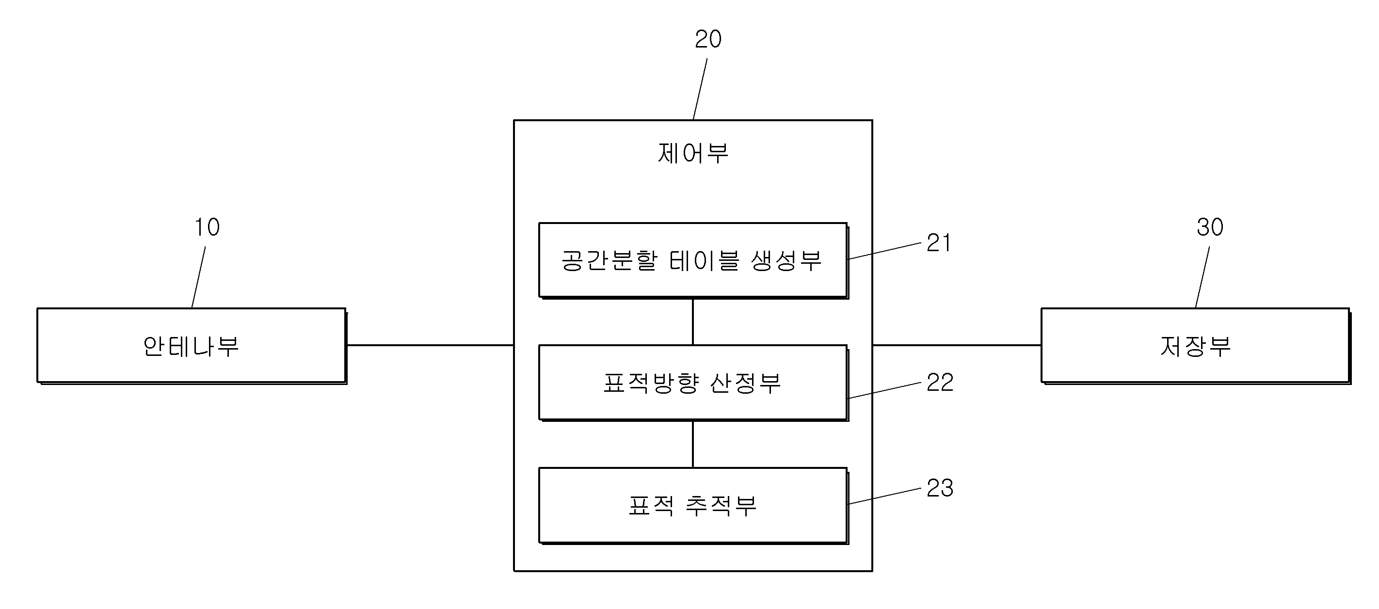
도 5를 참조할 때, 본 발명에 따른 배열안테나 기반 전방표적 추적장치는, 안테나부(10), 공간분할 테이블 생성부(21), 표적방향 산정부(23), 표적 추적부(25) 및 저장부(30)를 포함한다.5, an array antenna based target tracking device according to the present invention includes an
도 2를 참조하면, 안테나부(10)는 항공기나 미사일의 노즈부 외곽이나 동체 측면에 배치된다.2, the
안테나부(10)는 짝수(2N)개의 안테나를 폐곡선의 형태로 배열하고, 배열된 안테나 중 서로 마주보는 두 안테나를 쌍으로 하여 총 N회의 진폭 비교 기법을 적용하게 된다.The
즉, 배열안테나 전방에 하나의 표적이 위치하는 경우, 총 N개 안테나 쌍에서의 진폭 비교 결과값을 얻을 수 있다. 이 때, 각 안테나 쌍을 구성하는 두 안테나가 배열의 중앙을 기준으로 하여 서로 대칭으로 위치하면 되며, 안테나 간 간격이 일정하지 않거나 원형이 아닌 타원형 또는 기타의 다른 형태로 배치해도 무관하다.That is, if one target is located in front of the array antenna, the result of amplitude comparison in a total of N pairs of antennas can be obtained. In this case, the two antennas constituting each pair of antennas should be positioned symmetrically with respect to the center of the array, and may be arranged in a non-circular shape or an elliptical shape or other shapes.
공간분할 테이블 생성부(21)는 안테나부(10) 전방의 전반구 공간을 분할하여 공간분할 테이블을 형성하는 것이다.The space division
공간분할 테이블(space division table)은 표적을 추적하기 전에 미리 측정하여 파악한 진폭 비교 결과값과 표적의 방향간의 상관관계를 테이블의 형태로 저장부(30)에 저장되며, 추후 표적을 추적 시 활용되는 것이다.The space division table is stored in the
공간분할 테이블을 형성하기 위해서, 안테나부(10) 전방의 전반구 공간을 분할하여 분할된 각 공간의 꼭지점들에 대응하는 방위각/고각에서 사전 측정을 수행하고, 이를 통해 각 꼭지점에서 N개의 진폭 비교 결과값을 획득한다.In order to form a space division table, preliminary measurement is performed at an azimuth angle / elevation angle corresponding to vertices of each divided space by dividing the front half space in front of the
본 발명에서는 도 3과 같이 시선축에 근접할수록 공간의 크기가 작아지도록 하며, 시선축에서 멀어질수록 공간의 크기가 크도록 분할할 수 있으나, 이에 한정되지 않고 다른 공간분할 방법을 사용할 수 있음은 물론이다.In the present invention, as shown in FIG. 3, the size of the space is made smaller as the eye axis approaches the eye axis, and the size of the space is larger as the distance from the eye axis is larger. However, Of course.
하나의 분할된 공간에 대응하는 꼭지점들(도 3의 경우, 분할 공간 당 4개 또는 5개의 꼭지점)에서의 진폭 비교 결과값들을 이용하여, 해당 분할 공간에서의 진폭 비교 결과값의 범위(최소값 Amin, 최대값 Amax)를 N개 안테나 쌍에 대하여 각각 계산하여 테이블의 형태로 저장함으로써 도 4와 같은 공간분할테이블을 생성하게 된다.The amplitude comparison result values in the corresponding divided space (the minimum value Amin (i = 1, 2, 3, 4, 5, , Maximum value Amax) for each of the N antenna pairs and stores them in the form of a table, thereby generating a space division table as shown in FIG.
도 4를 참조하면, 분할 공간은 M개로 형성될 수 있으며, 각 분할 공간에는 4 개 혹은 5 개의 꼭지점 좌표(방위각, 고각)가 형성되며, 각 분할 공간에는 N개의 진폭 비교 축을 형성할 수 있다. Referring to FIG. 4, the number of division spaces may be M, and four or five vertex coordinates (azimuth angle, elevation angle) may be formed in each division space, and N amplitude comparison axes may be formed in each division space.
표적방향 산정부(23)는 공간분할 테이블을 생성하여 저장부(30)에 저장한 후, 공간분할 테이블의 테이블 값과 비교하여 표적이 위치할 것으로 예상되는 분할 공간을 결정하여 표적의 방향을 산정하는 것이다.The target
이때, 전자파를 방사 또는 반사하는 전방 표적이 존재할 경우, 2N개의 안테나들로부터 N개의 진폭 비교 결과값을 얻을 수 있다.At this time, if there is a forward target that emits or reflects electromagnetic waves, N amplitude comparison result values can be obtained from 2N antennas.
또한, 적이 위치할 것으로 예상되는 분할 공간의 수가 단수일 경우, 분할 공간에 대응하는 꼭지점들의 방위각/고각의 최대값과 최소값을 구하여 두 값의 평균을 표적의 방향으로 산정한다. 만약 분할 공간의 수가 복수일 경우, 해당 분할 공간들의 꼭지점들에 대응하는 방위각/고각의 최대값과 최소값을 구하여 두 값의 평균을 표적의 방향으로 산정한다.Also, when the number of the divided spaces expected to be located is a single number, the maximum value and the minimum value of the azimuth / elevation angle of the vertices corresponding to the divided space are obtained, and the average of the two values is calculated in the direction of the target. If there are a plurality of divided spaces, the maximum and minimum values of the azimuth / elevation corresponding to the vertices of the divided spaces are obtained, and the average of the two values is calculated in the direction of the target.
그러나, 상기와 같이 산정한 표적의 방향은 실제 표적의 방향과 정확히 일치하지 않을 수 있다.However, the direction of the target calculated as described above may not exactly coincide with the direction of the actual target.
이에, 표적의 방향으로 전방표적 추적장치를 지향하여 표적을 추적하게 된다.Thus, the target is traced by aiming the forward target tracking device in the direction of the target.
표적 추적부(25)는 제어 명령을 통해 표적의 방향으로 전방표적 추적장치를 지향하도록 하여 표적을 추적하는 것이다.The target tracking unit 25 tracks the target by directing the front target tracking apparatus in the direction of the target through a control command.
이 때, 방향탐지 및 추적 시스템을 표적의 방향으로 지향하는 방법은 크게 두 가지로, 김발(gimbal) 등을 이용하여 배열된 안테나들을 회전시키거나, 방향탐지 시스템을 탑재한 비행체(항공기나 미사일)를 회전시키는 방법이 있으나, 이에 제한되지 않는다.At this time, there are two methods of directing the direction detection and tracking system to the target direction. For example, there are two methods of rotating the antennas arranged by using gimbal or the like, or by using a flight vehicle (aircraft or missile) But the present invention is not limited thereto.
표적 추적부(25)는 표적의 방향이 기 설정된 문턱값(threshold) 이내에 도달할 때까지 표적의 방향을 산정하고 표적을 추적하는 과정을 반복함으로써 상기 표적을 정확하게 추적하게 된다.The target tracking unit 25 accurately tracks the target by repeating the process of estimating the direction of the target and tracking the target until the direction of the target reaches a predetermined threshold value.
본 발명에서 제안한 시스템의 추적 정확도는 상기한 문턱값에 의해 결정되며, 도 8을 참조하면, 문턱값의 크기와 공간분할테이블의 시선축 방향 분할 공간의 크기는 같도록 두어야 한다.The tracking accuracy of the system proposed in the present invention is determined by the above threshold value. Referring to FIG. 8, the size of the threshold value and the size of the segmented space in the direction of the gaze axis of the space partition table should be the same.
문턱값의 크기와 추적에 소요되는 시간 사이에는, 문턱값이 작을수록 추적 정확도가 향상되나, 추적에 소요되는 시간이 증가하는 trade-off 관계가 존재하므로 사용자가 운용 목적에 부합하는 수준의 문턱값을 설정하여 사용토록 한다.There is a trade-off relationship between the size of the threshold and the time required for tracking, as the threshold value is smaller, the tracking accuracy is improved. However, since the time required for tracking increases, a threshold value To be used.
이에 본 발명에 따르면, 안테나를 항공기나 미사일의 노즈부 외곽이나 동체 측면에 배열하여 전방 표적에 대한 방향탐지를 수행할 경우, 노즈부의 공간을 확보함으로써 노즈부를 다양한 용도로 활용할 수 있다.According to the present invention, when the antenna is arranged on the outside of the nose portion of the aircraft or the missile, or on the side surface of the fuselage to detect the direction of the forward target, the nose portion can be utilized for various purposes by securing the space of the nose portion.
또한, 본 발명에 따르면, 진폭 비교 결과값과 표적의 방향 간 상관관계를 3차원 공간상의 무수히 많은 관측점들에서 계산하여 저장하지 않고 공간분할테이블의 형태로 저장함으로써, 방향탐지 성능의 저하 없이도 사전 측정에 소요되는 시간과 노력 및 측정 결과를 저장하는 메모리를 큰 폭으로 절약할 수 있다.Also, according to the present invention, the correlation between the amplitude comparison result value and the direction of the target is calculated and stored in the form of a space division table without being calculated and stored at an infinite number of viewpoints in the three-dimensional space, The memory for storing the time, effort, and measurement results in the memory can be greatly saved.
도 6은 본 발명의 다른 실시예에 따른 배열안테나 기반 전방표적 추적방법을 나타내는 순서도이며, 도 7은 본 발명의 다른 실시예에 따른 공간분할 테이블 생성방법을 나타내는 순서도이다.FIG. 6 is a flowchart illustrating a method of tracking an anterior-antenna target based on an array antenna according to another embodiment of the present invention, and FIG. 7 is a flowchart illustrating a method of generating a space division table according to another embodiment of the present invention.
도 6을 참조할 때, 본 발명의 다른 실시예에 따른 배열안테나 기반 전방표적 추적방법은, 안테나부 전방의 전반구 공간을 분할하여 공간분할 테이블을 형성하는 단계(S100); 전자파를 방사 또는 반사하는 표적으로부터 신호를 수신하는 단계(S200); 상기 공간분할 테이블의 테이블 값과 비교하여 표적이 위치할 것으로 예상되는 분할 공간을 결정하는 단계(S300); 상기 분할 공간으로부터 표적의 방향을 산정하고 상기 표적의 방향으로 전방표적 추적장치를 지향하는 단계(S400); 및 상기 산정된 표적의 방향이 기설정 문턱값 이내인지 판단하는 단계(S500);를 포함한다.Referring to FIG. 6, an array antenna-based front target tracking method according to another embodiment of the present invention includes: forming a space division table by dividing a front half space in front of an antenna unit (S100); Receiving a signal from a target that emits or reflects electromagnetic waves (S200); Comparing a table value of the space partition table with a table value to determine a partition space in which the target is expected to be located (S300); Estimating a direction of the target from the divided space and directing the forward target tracking device in the direction of the target (S400); And determining whether a direction of the calculated target is within a preset threshold value (S500).
즉, 본 발명에 따른 배열안테나 기반 전방표적 추적방법은, 공간분할 테이블을 생성하여 저장부(30)에 저장한다. 이후, 전방에 전자파를 반사 또는 방사하는 표적이 존재하면, 2N 개의 안테나들로부터 N개의 진폭 비교 결과값을 획득하여 이를 저장된 공간분할 테이블의 값과 비교하여 표적이 위치할 것으로 예상되는 분할 공간을 결정한 후, 해당 분할 공간에서 표적의 방향을 산정하게 된다. 이후, 제어 명령을 통해 상기 표적의 방향으로 전방표적 추적장치를 지향하여 표적을 추적하게 되는데, 표적의 방향이 기 설정된 문턱값(threshold) 이내에 도달할 때까지 표적의 방향을 산정하고 표적을 추적하는 과정을 반복한다.That is, in the frontal target tracking method based on the array antenna according to the present invention, a space division table is generated and stored in the
여기서, 공간 분할 테이블을 형성하는 단계(S100)는, 방향탐지 시스템을 구성한 후(S110), 안테나 전방의 전반구 공간을 M개로 분할하는 단계(S120); 분할된 공간의 각 꼭지점들에 대응하는 방위각/고각에서 사전 측정을 수행하고, 사전 측정을 수행하고, 이를 통해 각 꼭지점에서 N개의 진폭 비교 결과값을 측정하는 단계(S130); 및 측정값의 최대, 최소를 진폭 비교 결과값 범위로 저장하는 단계(S140);를 포함한다.Here, the step S100 of forming the space division table may include a step S120 of forming a direction detection system (S110), dividing the front half space in front of the antenna into M (S120); Performing a preliminary measurement at an azimuth / elevation angle corresponding to each vertex of the divided space, performing preliminary measurement, and measuring N amplitude comparison result values at each vertex (S130); And storing the maximum and minimum values of the measured values in the range of the amplitude comparison result value (S140).
이때, 분할 공간은 M개로 형성될 수 있으며, 각 분할 공간에는 4 개 혹은 5 개의 꼭지점 좌표(방위각, 고각)가 형성되며, 각 분할 공간에는 N개의 진폭 비교 축을 형성할 수 있다. At this time, the divided space may be formed of M, and each divided space may have four or five vertex coordinates (azimuth angle, elevation angle), and N amplitude comparison axes may be formed in each divided space.
이에, 분할공간은 M개가 될 때까지 수행되며, 진폭 비교 축은 N 개가 될 때까지 수행된다.Thus, the division space is performed until the number of M is reached, and the amplitude comparison axis is performed until N times.
또한, 측정값의 최대값은 A11.max로부터 Amn.max로 표현될 수 있으며, 측정값의 최소값은 A11.min으로부터 Amn.min으로 표현될 수 있다.Further, the maximum value of the measured value can be expressed as A11.max to Amn.max, and the minimum value of the measured value can be expressed as A11.min to Amn.min.
판단하는 단계(S500)에서, 산정된 표적의 방향이 기설정 문턱값 이내인 경우, 표적의 추적을 종료하게 되며, 산정된 표적의 방향이 기설정 문턱값 이내가 아닌 경우, 상기 표적으로부터 신호를 수신하는 단계를 재수행하게 된다.If the direction of the calculated target is within the preset threshold value, the tracking of the target is terminated. If the calculated target direction is not within the predetermined threshold value, The receiving step is re-executed.
앞서 살펴본 실시 예는 본 발명이 속하는 기술분야에서 통상의 지식을 가진 자(이하 '당업자'라 한다)가 본 발명을 용이하게 실시할 수 있도록 하는 바람직한 실시 예일 뿐, 전술한 실시 예 및 첨부한 도면에 한정되는 것은 아니므로 이로 인해 본 발명의 권리범위가 한정되는 것은 아니다. 따라서, 본 발명의 기술적 사상을 벗어나지 않는 범위 내에서 여러 가지 치환, 변형 및 변경이 가능하다는 것이 당업자에게 있어 명백할 것이며, 당업자에 의해 용이하게 변경 가능한 부분도 본 발명의 권리범위에 포함됨은 자명하다.It is to be understood that both the foregoing general description and the following detailed description of the present invention are exemplary and explanatory only and are not restrictive of the invention, as claimed, and will be fully understood by those of ordinary skill in the art. The present invention is not limited thereto. It will be apparent to those skilled in the art that various substitutions, modifications and variations are possible within the scope of the present invention, and it is obvious that those parts easily changeable by those skilled in the art are included in the scope of the present invention .
10: 안테나부
21: 공간분할 테이블 생성부
23: 표적방향 산정부
25: 표적 추적부
30: 저장부10:
21: Space partition table generation unit
23: target direction calculating section
25: target tracking unit
30:
Claims (11)
상기 안테나부 전방의 전반구 공간을 M개로 분할하여 공간분할 테이블을 형성하는 공간분할 테이블 생성부;
상기 공간분할 테이블의 테이블 값과 비교하여 표적이 위치할 것으로 예상되는 분할 공간을 결정하여 표적의 방향을 산정하는 표적방향 산정부;
제어 명령을 통해 상기 표적의 방향으로 전방표적 추적장치를 지향하여 표적을 추적하는 표적 추적부; 및
상기 분할된 각 공간에 대응하는 진폭 비교 결과값을 저장하는 저장부;를 포함하며,
복수의 안테나를 이용하여 상기 안테나들에 수신되는 전력의 진폭의 크기비와 저장된 상기 진폭 비교 결과값의 상관관계를 비교함으로써 표적의 방향을 탐지 및 추적하는 것을 특징으로 하는 배열안테나 기반 전방표적 추적장치.An antenna unit disposed on the outside of the nose portion of the aircraft or the missile or on the side surface of the fuselage;
A space division table generation unit for dividing a total opening space in front of the antenna unit into M spaces to form a space division table;
A target direction estimating unit for calculating a direction of a target by comparing a table value of the space partition table and determining a partition space in which a target is expected to be located;
A target tracking unit for tracking a target by directing a forward target tracking device in the direction of the target through a control command; And
And a storage unit for storing amplitude comparison result values corresponding to the divided spaces,
Wherein the direction of the target is detected and tracked by comparing the magnitude ratio of amplitude of the power received by the antennas using the plurality of antennas to the stored amplitude comparison result value, .
상기 안테나부는 짝수(2N)개의 안테나를 폐곡선의 형태로 배열하도록 하여, 배열된 안테나 중 서로 마주보는 두 안테나를 쌍으로 하여 N 회의 진폭 비교 기법을 적용할 수 있는 것을 특징으로 하는 배열안테나 기반 전방표적 추적장치.The method according to claim 1,
Wherein the antenna unit is configured to arrange even number (2N) antennas in the form of a closed curve, so that N amplitude comparing techniques can be applied by pairing two antennas facing each other among the arranged antennas. Tracking device.
상기 공간분할 테이블은 분할된 각 공간의 꼭지점들에 대응하는 방위각/고각에서 사전 측정을 수행하고, 이를 통해 각 꼭지점에서 N개의 진폭 비교 결과값을 획득하여 형성되는 것을 특징으로 하는 배열안테나 기반 전방표적 추적장치.3. The method of claim 2,
Wherein the spatial partition table is formed by performing a pre-measurement at an azimuth / elevation angle corresponding to the vertices of each divided space and obtaining N amplitude comparison result values at each vertex through the preliminary measurement. Tracking device.
상기 공간분할 테이블은 해당 분할 공간에서의 진폭 비교 결과값의 범위(최대값 Amax, 최소값 Amin)를 N개 안테나 쌍에 대하여 각각 산정하여 테이블의 형태로 저장되는 것을 특징으로 하는 배열안테나 기반 전방표적 추적장치.The method of claim 3,
Wherein the spatial division table is stored in the form of a table by calculating the range (maximum value Amax, minimum value Amin) of the amplitude comparison result value in the corresponding divided space for each of N antenna pairs, Device.
상기 표적방향 산정부는, 상기 표적이 위치할 것으로 예상되는 분할 공간의 수가 단수일 경우, 분할 공간에 대응하는 꼭지점들의 방위각과 고각의 최대값과 최소값을 구하여 상기 최대값과 최소값의 평균을 상기 표적의 방향으로 산정하는 것을 특징으로 하는 배열안테나 기반 전방표적 추적장치.The method according to claim 1,
Wherein the target direction calculation unit obtains a maximum value and a minimum value of the azimuth angle and the elevation angle of the vertices corresponding to the divided space when the number of the divided spaces expected to locate the target is a single number, Directional target tracking unit based on the array antenna.
상기 표적방향 산정부는, 상기 표적이 위치할 것으로 예상되는 분할 공간의 수가 복수일 경우, 해당 분할 공간들의 꼭지점들에 대응하는 방위각과 고각의 최대값과 최소값을 구하여 상기 최대값과 최소값의 평균을 상기 표적의 방향으로 산정하는 것을 특징으로 하는 배열안테나 기반 전방표적 추적장치.The method according to claim 1,
Wherein the target direction calculation unit calculates a maximum value and a minimum value of an azimuth angle and an elevation angle corresponding to vertexes of the divided spaces when the number of the divided spaces expected to locate the target is plural, And the direction of the target is calculated in the direction of the target.
상기 표적 추적부는 표적의 방향이 기 설정된 문턱값(threshold) 이내에 도달할 때까지 표적의 방향을 산정하고 표적을 추적하는 과정을 반복하는 것을 특징으로 하는 배열안테나 기반 전방표적 추적장치.The method according to claim 1,
Wherein the target tracking unit repeats the process of estimating the direction of the target and tracking the target until the direction of the target reaches the predetermined threshold value.
전자파를 방사 또는 반사하는 표적으로부터 신호를 수신하는 단계;
상기 공간분할 테이블의 테이블 값과 비교하여 표적이 위치할 것으로 예상되는 분할 공간을 결정하는 단계;
상기 분할 공간으로부터 표적의 방향을 산정하고 상기 표적의 방향으로 전방표적 추적장치를 지향하는 단계; 및
상기 산정된 표적의 방향이 기설정 문턱값 이내인지 판단하는 단계;를 포함하는 배열안테나 기반 전방표적 추적방법.Forming a space division table by dividing a front half space in front of the antenna unit;
Receiving a signal from a target that emits or reflects electromagnetic waves;
Comparing a table value of the space partition table with a table value to determine a partition space where the target is expected to be located;
Calculating a direction of the target from the divided space and directing the forward target tracking device in the direction of the target; And
And determining whether a direction of the calculated target is within a preset threshold value.
상기 판단하는 단계에서, 상기 산정된 표적의 방향이 기설정 문턱값 이내인 경우, 표적의 추적을 종료하는 것을 특징으로 하는 배열안테나 기반 전방표적 추적방법.9. The method of claim 8,
Wherein the tracking of the target is terminated when the direction of the calculated target is within a predetermined threshold value in the determining step.
상기 판단하는 단계에서, 상기 산정된 표적의 방향이 기설정 문턱값 이내가 아닌 경우, 상기 표적으로부터 신호를 수신하는 단계를 재수행하는 것을 특징으로 하는 배열안테나 기반 전방표적 추적방법.9. The method of claim 8,
Wherein if the direction of the calculated target is not within a preset threshold value, the step of receiving a signal from the target is re-executed.
상기 공간분할 테이블을 형성하는 단계는,
안테나 전방의 전반구 공간을 M개로 분할하는 단계;
분할된 공간의 각 꼭지점들에 대응하는 방위각/고각에서 사전 측정을 수행하고, 이를 통해 각 꼭지점에서 N개의 진폭 비교 결과값을 측정하는 단계; 및
측정값의 최대, 최소를 진폭 비교 결과값 범위로 저장하는 단계;를 포함하는 것을 특징으로 하는 배열안테나 기반 전방표적 추적방법.
9. The method of claim 8,
Wherein the forming the space partition table comprises:
Dividing a total opening space in front of the antenna into M pieces;
Performing preliminary measurements at azimuth / elevation angles corresponding to respective vertices of the divided space, and measuring N amplitude comparison result values at each vertex; And
And storing the maximum and minimum values of the measured values in the range of the amplitude comparison result value.
Priority Applications (1)
| Application Number | Priority Date | Filing Date | Title |
|---|---|---|---|
| KR1020170027487A KR101907776B1 (en) | 2017-03-03 | 2017-03-03 | Frontal target detection and tracking apparatus based on array antenna and method thereof |
Applications Claiming Priority (1)
| Application Number | Priority Date | Filing Date | Title |
|---|---|---|---|
| KR1020170027487A KR101907776B1 (en) | 2017-03-03 | 2017-03-03 | Frontal target detection and tracking apparatus based on array antenna and method thereof |
Publications (2)
| Publication Number | Publication Date |
|---|---|
| KR20180100943A KR20180100943A (en) | 2018-09-12 |
| KR101907776B1 true KR101907776B1 (en) | 2018-10-12 |
Family
ID=63593415
Family Applications (1)
| Application Number | Title | Priority Date | Filing Date |
|---|---|---|---|
| KR1020170027487A Active KR101907776B1 (en) | 2017-03-03 | 2017-03-03 | Frontal target detection and tracking apparatus based on array antenna and method thereof |
Country Status (1)
| Country | Link |
|---|---|
| KR (1) | KR101907776B1 (en) |
Citations (1)
| Publication number | Priority date | Publication date | Assignee | Title |
|---|---|---|---|---|
| KR101632471B1 (en) | 2013-04-02 | 2016-06-21 | 마크 리소시스, 인코포레이티드 | Radar system for continuous tracking of multiple objects |
Family Cites Families (1)
| Publication number | Priority date | Publication date | Assignee | Title |
|---|---|---|---|---|
| KR101276260B1 (en) | 2012-03-27 | 2013-06-20 | (주)뮤트로닉스 | Antenna for fuze sensor |
-
2017
- 2017-03-03 KR KR1020170027487A patent/KR101907776B1/en active Active
Patent Citations (1)
| Publication number | Priority date | Publication date | Assignee | Title |
|---|---|---|---|---|
| KR101632471B1 (en) | 2013-04-02 | 2016-06-21 | 마크 리소시스, 인코포레이티드 | Radar system for continuous tracking of multiple objects |
Also Published As
| Publication number | Publication date |
|---|---|
| KR20180100943A (en) | 2018-09-12 |
Similar Documents
| Publication | Publication Date | Title |
|---|---|---|
| US8369184B2 (en) | Systems and methods with improved three-dimensional source location processing including constraint of location solutions to a two-dimensional plane | |
| JP6328789B2 (en) | Method and apparatus for determining angle of arrival (AOA) in a radar warning receiver | |
| US8567077B2 (en) | Laser tracker system and technique for antenna boresight alignment | |
| US9081092B1 (en) | Covariance rotation with perspective projection for creating radar search volumes from remote cues | |
| JPS60249074A (en) | Method for estimating track of flying body | |
| CN108614268B (en) | Acoustic tracking method for low-altitude high-speed flying target | |
| CN108333588A (en) | For obtaining the alternative manner of direction ambiguity degree parsing | |
| KR100902559B1 (en) | Radar interferometer and target position estimation method using the same | |
| JP2017508162A (en) | Synthetic antenna sonar and method for forming a synthetic antenna beam | |
| CN106546947A (en) | A kind of single hydrophone Passive Location of joint waveguide invariant and line spectrum | |
| KR101240632B1 (en) | Underwater localization method and system using electromagnetic wave | |
| RU2623452C1 (en) | Method of navigation of moving objects | |
| RU2559820C1 (en) | Method for navigation of moving objects | |
| CN106772305A (en) | The Targets Dots fusion method of centralized MIMO radar under a kind of nonopiate waveform | |
| CN106338724B (en) | Machine sweeps the acquisition methods of metric wave MIMO three-dimensional radar power | |
| KR101907776B1 (en) | Frontal target detection and tracking apparatus based on array antenna and method thereof | |
| KR101852297B1 (en) | Apparatus and method for detecting position | |
| CN104977559B (en) | Target positioning method in interference environment | |
| CN118534447A (en) | Ultra-short baseline ten-array-element acoustic array and positioning method thereof | |
| KR102202072B1 (en) | Scattering position detection system | |
| Ash et al. | Performance of shockwave-based shooter localization under model misspecification | |
| Mirbach et al. | A simple surface estimation algorithm for UWB pulse radars based on trilateration | |
| KR102156401B1 (en) | A multi static radar system for stealth aircraft detection | |
| US8436762B2 (en) | Determining at least one coordinate of an object using intersecting surfaces | |
| KR102162332B1 (en) | Frontal target tracking apparatus and tracking method thereof |
Legal Events
| Date | Code | Title | Description |
|---|---|---|---|
| A201 | Request for examination | ||
| PA0109 | Patent application |
Patent event code: PA01091R01D Comment text: Patent Application Patent event date: 20170303 |
|
| PA0201 | Request for examination | ||
| E902 | Notification of reason for refusal | ||
| PE0902 | Notice of grounds for rejection |
Comment text: Notification of reason for refusal Patent event date: 20180417 Patent event code: PE09021S01D |
|
| PG1501 | Laying open of application | ||
| E701 | Decision to grant or registration of patent right | ||
| PE0701 | Decision of registration |
Patent event code: PE07011S01D Comment text: Decision to Grant Registration Patent event date: 20181002 |
|
| PR0701 | Registration of establishment |
Comment text: Registration of Establishment Patent event date: 20181005 Patent event code: PR07011E01D |
|
| PR1002 | Payment of registration fee |
Payment date: 20181005 End annual number: 3 Start annual number: 1 |
|
| PG1601 | Publication of registration | ||
| PR1001 | Payment of annual fee |
Payment date: 20211005 Start annual number: 4 End annual number: 4 |
|
| PR1001 | Payment of annual fee |
Payment date: 20221005 Start annual number: 5 End annual number: 5 |
|
| PR1001 | Payment of annual fee |
Payment date: 20231005 Start annual number: 6 End annual number: 6 |