KR101907340B1 - Computer server thermal control using integrated precision airflow - Google Patents
Computer server thermal control using integrated precision airflow Download PDFInfo
- Publication number
- KR101907340B1 KR101907340B1 KR1020177035419A KR20177035419A KR101907340B1 KR 101907340 B1 KR101907340 B1 KR 101907340B1 KR 1020177035419 A KR1020177035419 A KR 1020177035419A KR 20177035419 A KR20177035419 A KR 20177035419A KR 101907340 B1 KR101907340 B1 KR 101907340B1
- Authority
- KR
- South Korea
- Prior art keywords
- airflow
- server
- cartridge
- opening
- stand
- Prior art date
- Legal status (The legal status is an assumption and is not a legal conclusion. Google has not performed a legal analysis and makes no representation as to the accuracy of the status listed.)
- Active
Links
- 238000000034 method Methods 0.000 claims abstract description 30
- 238000001816 cooling Methods 0.000 claims abstract description 15
- 238000013022 venting Methods 0.000 claims abstract description 3
- 238000004891 communication Methods 0.000 claims description 27
- 239000012530 fluid Substances 0.000 claims description 22
- 230000000153 supplemental effect Effects 0.000 claims description 7
- 239000011800 void material Substances 0.000 claims description 7
- 238000003795 desorption Methods 0.000 claims description 5
- 230000002093 peripheral effect Effects 0.000 claims description 4
- 230000000903 blocking effect Effects 0.000 claims description 3
- 230000000295 complement effect Effects 0.000 claims description 3
- 238000007599 discharging Methods 0.000 claims description 3
- 229940014425 exodus Drugs 0.000 claims description 2
- 230000004941 influx Effects 0.000 claims description 2
- 238000007789 sealing Methods 0.000 description 12
- 239000007789 gas Substances 0.000 description 6
- 230000008901 benefit Effects 0.000 description 3
- 238000010586 diagram Methods 0.000 description 3
- 239000013536 elastomeric material Substances 0.000 description 3
- 230000004044 response Effects 0.000 description 3
- 238000013461 design Methods 0.000 description 2
- 230000017525 heat dissipation Effects 0.000 description 2
- 239000011261 inert gas Substances 0.000 description 2
- 239000007788 liquid Substances 0.000 description 2
- 238000012544 monitoring process Methods 0.000 description 2
- 230000003213 activating effect Effects 0.000 description 1
- 238000004378 air conditioning Methods 0.000 description 1
- 239000002826 coolant Substances 0.000 description 1
- 230000008878 coupling Effects 0.000 description 1
- 238000010168 coupling process Methods 0.000 description 1
- 238000005859 coupling reaction Methods 0.000 description 1
- 230000000694 effects Effects 0.000 description 1
- 239000013013 elastic material Substances 0.000 description 1
- 230000005611 electricity Effects 0.000 description 1
- 238000005516 engineering process Methods 0.000 description 1
- 238000001704 evaporation Methods 0.000 description 1
- 230000008020 evaporation Effects 0.000 description 1
- 239000004744 fabric Substances 0.000 description 1
- 238000012986 modification Methods 0.000 description 1
- 230000004048 modification Effects 0.000 description 1
- 230000005855 radiation Effects 0.000 description 1
Images


Classifications
-
- H—ELECTRICITY
- H05—ELECTRIC TECHNIQUES NOT OTHERWISE PROVIDED FOR
- H05K—PRINTED CIRCUITS; CASINGS OR CONSTRUCTIONAL DETAILS OF ELECTRIC APPARATUS; MANUFACTURE OF ASSEMBLAGES OF ELECTRICAL COMPONENTS
- H05K7/00—Constructional details common to different types of electric apparatus
- H05K7/20—Modifications to facilitate cooling, ventilating, or heating
- H05K7/20709—Modifications to facilitate cooling, ventilating, or heating for server racks or cabinets; for data centers, e.g. 19-inch computer racks
- H05K7/20718—Forced ventilation of a gaseous coolant
- H05K7/20745—Forced ventilation of a gaseous coolant within rooms for removing heat from cabinets, e.g. by air conditioning device
-
- F—MECHANICAL ENGINEERING; LIGHTING; HEATING; WEAPONS; BLASTING
- F16—ENGINEERING ELEMENTS AND UNITS; GENERAL MEASURES FOR PRODUCING AND MAINTAINING EFFECTIVE FUNCTIONING OF MACHINES OR INSTALLATIONS; THERMAL INSULATION IN GENERAL
- F16K—VALVES; TAPS; COCKS; ACTUATING-FLOATS; DEVICES FOR VENTING OR AERATING
- F16K27/00—Construction of housing; Use of materials therefor
-
- F—MECHANICAL ENGINEERING; LIGHTING; HEATING; WEAPONS; BLASTING
- F16—ENGINEERING ELEMENTS AND UNITS; GENERAL MEASURES FOR PRODUCING AND MAINTAINING EFFECTIVE FUNCTIONING OF MACHINES OR INSTALLATIONS; THERMAL INSULATION IN GENERAL
- F16K—VALVES; TAPS; COCKS; ACTUATING-FLOATS; DEVICES FOR VENTING OR AERATING
- F16K3/00—Gate valves or sliding valves, i.e. cut-off apparatus with closing members having a sliding movement along the seat for opening and closing
- F16K3/02—Gate valves or sliding valves, i.e. cut-off apparatus with closing members having a sliding movement along the seat for opening and closing with flat sealing faces; Packings therefor
- F16K3/0209—Gate valves or sliding valves, i.e. cut-off apparatus with closing members having a sliding movement along the seat for opening and closing with flat sealing faces; Packings therefor the valve having a particular passage, e.g. provided with a filter, throttle or safety device
-
- F—MECHANICAL ENGINEERING; LIGHTING; HEATING; WEAPONS; BLASTING
- F16—ENGINEERING ELEMENTS AND UNITS; GENERAL MEASURES FOR PRODUCING AND MAINTAINING EFFECTIVE FUNCTIONING OF MACHINES OR INSTALLATIONS; THERMAL INSULATION IN GENERAL
- F16K—VALVES; TAPS; COCKS; ACTUATING-FLOATS; DEVICES FOR VENTING OR AERATING
- F16K3/00—Gate valves or sliding valves, i.e. cut-off apparatus with closing members having a sliding movement along the seat for opening and closing
- F16K3/02—Gate valves or sliding valves, i.e. cut-off apparatus with closing members having a sliding movement along the seat for opening and closing with flat sealing faces; Packings therefor
- F16K3/03—Gate valves or sliding valves, i.e. cut-off apparatus with closing members having a sliding movement along the seat for opening and closing with flat sealing faces; Packings therefor with a closure member in the form of an iris-diaphragm
-
- H01L35/28—
-
- H—ELECTRICITY
- H05—ELECTRIC TECHNIQUES NOT OTHERWISE PROVIDED FOR
- H05K—PRINTED CIRCUITS; CASINGS OR CONSTRUCTIONAL DETAILS OF ELECTRIC APPARATUS; MANUFACTURE OF ASSEMBLAGES OF ELECTRICAL COMPONENTS
- H05K7/00—Constructional details common to different types of electric apparatus
- H05K7/20—Modifications to facilitate cooling, ventilating, or heating
- H05K7/20009—Modifications to facilitate cooling, ventilating, or heating using a gaseous coolant in electronic enclosures
- H05K7/20136—Forced ventilation, e.g. by fans
- H05K7/20145—Means for directing air flow, e.g. ducts, deflectors, plenum or guides
-
- H—ELECTRICITY
- H05—ELECTRIC TECHNIQUES NOT OTHERWISE PROVIDED FOR
- H05K—PRINTED CIRCUITS; CASINGS OR CONSTRUCTIONAL DETAILS OF ELECTRIC APPARATUS; MANUFACTURE OF ASSEMBLAGES OF ELECTRICAL COMPONENTS
- H05K7/00—Constructional details common to different types of electric apparatus
- H05K7/20—Modifications to facilitate cooling, ventilating, or heating
- H05K7/20009—Modifications to facilitate cooling, ventilating, or heating using a gaseous coolant in electronic enclosures
- H05K7/20136—Forced ventilation, e.g. by fans
- H05K7/20181—Filters; Louvers
-
- H—ELECTRICITY
- H05—ELECTRIC TECHNIQUES NOT OTHERWISE PROVIDED FOR
- H05K—PRINTED CIRCUITS; CASINGS OR CONSTRUCTIONAL DETAILS OF ELECTRIC APPARATUS; MANUFACTURE OF ASSEMBLAGES OF ELECTRICAL COMPONENTS
- H05K7/00—Constructional details common to different types of electric apparatus
- H05K7/20—Modifications to facilitate cooling, ventilating, or heating
- H05K7/20709—Modifications to facilitate cooling, ventilating, or heating for server racks or cabinets; for data centers, e.g. 19-inch computer racks
- H05K7/20718—Forced ventilation of a gaseous coolant
- H05K7/20727—Forced ventilation of a gaseous coolant within server blades for removing heat from heat source
-
- H—ELECTRICITY
- H05—ELECTRIC TECHNIQUES NOT OTHERWISE PROVIDED FOR
- H05K—PRINTED CIRCUITS; CASINGS OR CONSTRUCTIONAL DETAILS OF ELECTRIC APPARATUS; MANUFACTURE OF ASSEMBLAGES OF ELECTRICAL COMPONENTS
- H05K7/00—Constructional details common to different types of electric apparatus
- H05K7/20—Modifications to facilitate cooling, ventilating, or heating
- H05K7/20709—Modifications to facilitate cooling, ventilating, or heating for server racks or cabinets; for data centers, e.g. 19-inch computer racks
- H05K7/20718—Forced ventilation of a gaseous coolant
- H05K7/20736—Forced ventilation of a gaseous coolant within cabinets for removing heat from server blades
-
- H—ELECTRICITY
- H10—SEMICONDUCTOR DEVICES; ELECTRIC SOLID-STATE DEVICES NOT OTHERWISE PROVIDED FOR
- H10N—ELECTRIC SOLID-STATE DEVICES NOT OTHERWISE PROVIDED FOR
- H10N10/00—Thermoelectric devices comprising a junction of dissimilar materials, i.e. devices exhibiting Seebeck or Peltier effects
- H10N10/10—Thermoelectric devices comprising a junction of dissimilar materials, i.e. devices exhibiting Seebeck or Peltier effects operating with only the Peltier or Seebeck effects
-
- A—HUMAN NECESSITIES
- A62—LIFE-SAVING; FIRE-FIGHTING
- A62C—FIRE-FIGHTING
- A62C37/00—Control of fire-fighting equipment
- A62C37/36—Control of fire-fighting equipment an actuating signal being generated by a sensor separate from an outlet device
- A62C37/38—Control of fire-fighting equipment an actuating signal being generated by a sensor separate from an outlet device by both sensor and actuator, e.g. valve, being in the danger zone
- A62C37/40—Control of fire-fighting equipment an actuating signal being generated by a sensor separate from an outlet device by both sensor and actuator, e.g. valve, being in the danger zone with electric connection between sensor and actuator
-
- F—MECHANICAL ENGINEERING; LIGHTING; HEATING; WEAPONS; BLASTING
- F15—FLUID-PRESSURE ACTUATORS; HYDRAULICS OR PNEUMATICS IN GENERAL
- F15B—SYSTEMS ACTING BY MEANS OF FLUIDS IN GENERAL; FLUID-PRESSURE ACTUATORS, e.g. SERVOMOTORS; DETAILS OF FLUID-PRESSURE SYSTEMS, NOT OTHERWISE PROVIDED FOR
- F15B2211/00—Circuits for servomotor systems
- F15B2211/40—Flow control
- F15B2211/405—Flow control characterised by the type of flow control means or valve
- F15B2211/40523—Flow control characterised by the type of flow control means or valve with flow dividers
- F15B2211/4053—Flow control characterised by the type of flow control means or valve with flow dividers using valves
-
- F—MECHANICAL ENGINEERING; LIGHTING; HEATING; WEAPONS; BLASTING
- F16—ENGINEERING ELEMENTS AND UNITS; GENERAL MEASURES FOR PRODUCING AND MAINTAINING EFFECTIVE FUNCTIONING OF MACHINES OR INSTALLATIONS; THERMAL INSULATION IN GENERAL
- F16K—VALVES; TAPS; COCKS; ACTUATING-FLOATS; DEVICES FOR VENTING OR AERATING
- F16K11/00—Multiple-way valves, e.g. mixing valves; Pipe fittings incorporating such valves
- F16K11/10—Multiple-way valves, e.g. mixing valves; Pipe fittings incorporating such valves with two or more closure members not moving as a unit
-
- F—MECHANICAL ENGINEERING; LIGHTING; HEATING; WEAPONS; BLASTING
- F16—ENGINEERING ELEMENTS AND UNITS; GENERAL MEASURES FOR PRODUCING AND MAINTAINING EFFECTIVE FUNCTIONING OF MACHINES OR INSTALLATIONS; THERMAL INSULATION IN GENERAL
- F16K—VALVES; TAPS; COCKS; ACTUATING-FLOATS; DEVICES FOR VENTING OR AERATING
- F16K27/00—Construction of housing; Use of materials therefor
- F16K27/003—Housing formed from a plurality of the same valve elements
-
- H—ELECTRICITY
- H05—ELECTRIC TECHNIQUES NOT OTHERWISE PROVIDED FOR
- H05K—PRINTED CIRCUITS; CASINGS OR CONSTRUCTIONAL DETAILS OF ELECTRIC APPARATUS; MANUFACTURE OF ASSEMBLAGES OF ELECTRICAL COMPONENTS
- H05K7/00—Constructional details common to different types of electric apparatus
- H05K7/20—Modifications to facilitate cooling, ventilating, or heating
- H05K7/20709—Modifications to facilitate cooling, ventilating, or heating for server racks or cabinets; for data centers, e.g. 19-inch computer racks
- H05K7/20836—Thermal management, e.g. server temperature control
Landscapes
- Engineering & Computer Science (AREA)
- General Engineering & Computer Science (AREA)
- Microelectronics & Electronic Packaging (AREA)
- Physics & Mathematics (AREA)
- Thermal Sciences (AREA)
- Mechanical Engineering (AREA)
- Computer Hardware Design (AREA)
- Cooling Or The Like Of Electrical Apparatus (AREA)
Abstract
본 발명에 의하여 컴퓨터 장비(305)의 유리한 냉각을 위한 시스템, 방법, 및 랙 스탠드 부분이 제공된다. 랙 스탠드(200)는 카트리지(2416)들로 형성될 수 있는 중공 몸체(210, 212)를 포함한다. 기류 소스(5204)로부터의 기체는 랙 스탠드 몸체 안으로 안내되고, 그 다음에 컴퓨터 장비의 밀봉된 케이스 안으로 안내된다. 그 다음 공기 유동은 순환, 배출, 또는 다른 목적을 위해서 컴퓨터 장비 밖으로 안내된다.A system, method, and rack stand portion for advantageous cooling of computer equipment 305 is provided by the present invention. The rack stand 200 includes hollow bodies 210, 212 that can be formed from cartridges 2416. [ The gas from the airflow source 5204 is guided into the rack stand body and then guided into a sealed case of computer equipment. The air flow is then guided out of the computer equipment for circulation, venting, or other purposes.
Description
본 발명은 컴퓨터 서버 랙에 관한 것으로서, 구체적으로는 열 분산을 위하여 서버들 및 다른 네트워크 장치들과 같은 전기 장비에 기류를 효율적으로 지향시키는데에 사용될 수 있는 컴퓨터 서버 랙 시스템에 관한 것이다.The present invention relates to computer server racks, and more particularly to computer server rack systems that can be used to efficiently direct airflow to electrical equipment such as servers and other network devices for heat dissipation.
현존하는 랙-장착식 서버 시스템은 서버 랙과 상기 서버 랙에 수용되는 복수의 서버 유닛들을 포함한다. 통상적으로 서버 유닛들 각각은 한 쌍의 장착용 브라켓, 또는 서버 랙의 대향된 측벽들의 내측 표면에 각각 고정된 레일들에 의하여 서버 랙에 장착된다. 열 분산을 도모하기 위하여 전자 장비로 공기 및 다른 유체를 지향시키기 위한 많은 노력들이 있어 왔다.Existing rack-mountable server systems include a server rack and a plurality of server units housed in the server rack. Typically, each of the server units is mounted to a server rack by a pair of mounting brackets, or rails respectively secured to the inner surface of the opposing side walls of the server rack. There have been many efforts to direct air and other fluids to electronic equipment to promote heat dissipation.
본 발명은 종래 기술을 개선하는 컴퓨터 서버 열 통제를 제공함을 목적으로 한다.The present invention is directed to providing computer server thermal control to improve the prior art.
본 발명에 따른 서버 랙은 그 장치의 전방 측부들 및 후방 측부들에 중공 튜브형 지지 포스트들을 구비한 프레임을 포함한다. 상기 전방 포스트들 사이와 후방 포스트들 사이에는 전방 측부 패널들과 후방 측부 패널들이 배치된다. 상기 패널들은 밸브 부재들을 구비한 카트리지들을 보충적으로 수용하며, 상기 밸브 부재들은 공기 유동(기류)이 후방 공동으로부터 카트리지들 내의 통로들과 레일을 통해서 서버들 안으로 진행함을 제어한다. 서버들을 수용하기 위한 복수의 측부 레일들은 상기 전방 포스트 및 후방 포스트에 결합된다. 상기 레일들에는 서버들의 측벽들에 제공되어 있는 통로들과 대응되는 통로들이 측벽을 통해 형성되어 있다.A server rack according to the present invention includes a frame having hollow tubular support posts on the front side and rear sides of the apparatus. Front side panels and rear side panels are disposed between the front posts and between the rear posts. The panels complementarily receive cartridges with valve members, which control airflow (airflow) from the rear cavity through the passages in the cartridges and the rails into the servers. A plurality of side rails for receiving the servers are coupled to the front and rear posts. The rails are provided with passages corresponding to the passages provided on the side walls of the servers through the side walls.
바람직한 일 실시예에서, 공기조화 처리가 된 공기가 전방 측부 패널들의 상부 표면 및 하부 표면에 제공되어 있는 통로들을 통해서 전방 측부 패널들로 도입된다. 그 다음 공기는 상기 전방 패널로부터 카트리지 부재를 통하도록 형성된 하나 이상의 통로를 통하여, 서버의 측방 측벽에 제공되어 있는 통로를 통해서 서버의 전방 섹션으로 이동한다. 공기는 서버를 통해서 서버의 전방 섹션으로부터 후방 섹션으로 이동하고, 그 다음에 측방 측벽에 있는 통로를 통해서 후방 패널에 제공되어 있는 카트리지로 나간다. 그 다음 공기는 순환을 위하여 공기 조화기 유닛으로 복귀한다.In one preferred embodiment, the air-conditioned air is introduced into the front side panels through passages provided on the top and bottom surfaces of the front side panels. The air then travels from the front panel through one or more passageways formed through the cartridge member to the front section of the server through the passageways provided in the side walls of the server. Air travels from the front section of the server through the server to the rear section, and then through the passageway in the side walls to the cartridge provided in the rear panel. The air then returns to the air conditioner unit for circulation.
일 실시예에서 서버 랙은 대략 6피트의 높이를 가지며, 4.445 cm (1.75 inch)의 간격으로 42개의 서버 유닛을 수용하도록 설계된다. 레일 부재들은 측부 패널들 상의 각 유닛 세그먼트에 제공되고 서버를 지지한다. 아래에서 설명되는 실시예들에서, 카트리지들을 통하는 통로들은 개별적으로 전자기계적으로 또는 수작업으로 제어될 수 있는 적어도 하나의 밸브 부재를 구비한다. 특정 랙 유닛에 서버가 제공되지 않은 경우 또는 기타 다른 이유로 특정 서버 유닛에서 온도가 적절히 제어되는 경우에는 상기 구멍이 폐쇄될 수 있다. 실시예들에서, 콘트롤러는 온도계로부터의 신호에 응답하여 카트리지들에 제공되어 있는 밸브 부재들을 자동적으로 개방 또는 폐쇄한다.In one embodiment, the server rack is approximately six feet high and is designed to accommodate 42 server units at an interval of 4.4 inches (1.75 inches). The rail members are provided in each unit segment on the side panels and support the server. In the embodiments described below, the passages through the cartridges have at least one valve member that can be individually electromechanically or manually controlled. The hole may be closed if the server is not provided for a particular rack unit or if the temperature is properly controlled at a particular server unit for some other reason. In embodiments, the controller automatically opens or closes the valve members provided to the cartridges in response to a signal from the thermometer.
따라서, 서버에 대한 냉각 필요에 따라서 각 서버와 관련된 밸브들 또는 통로들이 가변적으로 개방 및 폐쇄될 수 있다는 것이 이해될 것이다. 또한, 여기에서 설명되는 바와 같이, 상기 구멍을 통하는 공기 유동의 정도는 댐퍼 또는 둑(weir) 구조를 이용하여 제어될 수 있다. 그러므로, 실시예들에서 국부적 콘트롤러가 제공될 수 있으며, 이것은 서버의 온도를 독출하는 온도계로부터 입력 정보를 수신하여 그에 따라 밸브 구멍의 개방 및 폐쇄를 조절할 수 있다. 대안적으로는 상기 댐퍼가 수작업으로 조절될 수 있다. 또 다른 실시예에서는 중앙 콘트롤러가 복수의 서버 랙으로부터의 신호들을 수신한다.It will thus be appreciated that the valves or passageways associated with each server may be variably opened and closed depending on the cooling needs for the server. Also, as described herein, the degree of air flow through the bore can be controlled using a damper or weir structure. Thus, in embodiments, a local controller may be provided, which receives input information from a thermometer reading the temperature of the server and thereby regulates the opening and closing of the valve opening. Alternatively, the damper can be manually adjusted. In yet another embodiment, the central controller receives signals from a plurality of server racks.
상기 포스트에 있는 개구들 각각에는 분리가능한 밀봉재가 제공되어 있는바, 이것은 서버의 특정 구성형태에 따라서 유동을 막을 수 있다. 실시예들에서는, 상기 포스트들로부터 유연성 매니폴드가 연장되어 유체를 서버들에 제공되어 있는 접근 영역으로 그리고 그 접근 영역으로부터 다른 곳으로 지향시킨다. 바람직한 실시예는 공기 유동의 사용을 전제로 하지만, 일부 실시에에서는 상기 프레임이 액체를 수용하도록 구성될 수 있으며, 상기 포스트들 및 매니폴드는 그 유체를 개별 서버들과 결합되는 열교환 요소들로 그 유체를 안내한다.Each of the openings in the post is provided with a detachable seal, which may prevent flow depending on the particular configuration of the server. In embodiments, a flexible manifold extends from the posts to direct fluid to and from the access area being provided to the servers. Although the preferred embodiment presupposes the use of air flow, in some implementations the frame may be configured to receive the liquid, which posts and manifolds may be heated by heat exchange elements Guide the fluid.
또 다른 실시예에서 상기 랙은 액체 유동 및 공기 유동 모두를 허용하도록 구성된다.In another embodiment, the rack is configured to allow both liquid flow and air flow.
본 발명에 따라 제공되는 서버 시설(server facility)은: 포위된 빌딩 내부를 한정하는 빌딩으로서, 상기 빌딩 내에서의 기체의 밀봉된 이동을 위한 빌딩 유입 도관(building inlet conduit) 및 기체를 열원(熱源; heat reservoir)으로 배출하기 위한 유출 도관을 구비한, 빌딩; 측방 지지 부재들을 포함하는 서버 랙 스탠드(server rack stand)로서, 상기 측방 지지 부재들은 내부 공동(interior void), 상기 빌딩 유입 도관과 유체소통(fluid communication)되는 기류 유입 통로, 및 상기 빌딩 유출 도관과 유체소통되는 기류 유출 통로를 한정하는, 서버 랙 스탠드; 상기 서버 랙 스탠드의 측방 지지 부재들 사이에서 분리가능하게 고정되도록 구성되고 실질적으로 밀봉된 컴퓨터로서, 상기 고정시 상기 기류 유입 통로 및 상기 기류 유출 통로와 개별적으로 인접하게 위치되는 치수를 가진 기류 유입 개구 및 기류 유출 개구를 한정하는 케이스(case)를 구비한, 컴퓨터; 상기 기류 유입 개구와 상기 기류 유입 통로 사이, 그리고 상기 기류 유출 개구와 상기 기류 유출 통로 사이에 밀봉 연결부(sealed connection)를 형성하는 서버 도관(server conduit); 및 공기를 상기 빌딩 유입 도관으로부터 상기 열원까지 강제로 진행시키기 위한 기류 소스(airflow source);를 포함하며, 상기 서버 랙 스탠드는, 상기 내부 공동을 한정하는 패널, 한 쌍의 주변 포스트(peripheral post)들, 및 상기 측방 포스트(lateral post)들 사이에 분리가능하게 배치되어 상기 기류 유출부와 상기 서버 랙 공동의 측벽을 한정하는 적어도 하나의 카트리지(cartridge)를 포함한다.A server facility provided in accordance with the present invention is a building that defines an enclosed building, comprising a building inlet conduit for sealing movement of the gas within the building, a building having an outlet conduit for discharging into a heat reservoir; A server rack stand comprising side support members, the side support members comprising an interior void, an air flow inlet channel in fluid communication with the building inlet conduit, A server rack stand defining the airflow outlet passage in fluid communication; A substantially enclosed computer configured to be releasably secured between side support members of the server rack stand, the airflow inflow opening having a dimension positioned separately adjacent to the airflow inflow passage and the airflow outflow passage at the time of fixation, And a case defining a flow-out opening; A server conduit defining a sealed connection between the air inlet opening and the air inlet opening, and between the air outlet opening and the air outlet opening; And an airflow source for forcing the air to flow from the building inlet conduit to the heat source, wherein the server rack stand comprises a panel defining the interior cavity, a pair of peripheral posts, And at least one cartridge detachably disposed between the lateral posts to define a sidewall of the airflow outlet and the server rack cavity.
일 실시예에서, 상기 서버 랙 스탠드는 중공 챔버(hollow chamber)를 한정하는 측방 포스트들을 포함하고, 상기 측방 포스트들 내부에서 상기 중공 챔버는 상기 빌딩 유입 도관 및 상기 스탠드 내부 공동과 유체소통된다. 다른 일 실시예에서, 상기 스탠드에 포함되는 상기 공동 측벽(void sidewall)은 복수개의 상기 카트리지로 이루어진다. 또 다른 실시예에서, 상기 카트리지들은 상기 스탠드로부터 상기 케이스 안으로의 기류를 막도록 구성된 장애물(impediment)을 포함하고, 상기 장애물은 선택적으로 작동가능하다.In one embodiment, the server rack stand includes lateral posts defining a hollow chamber within which the hollow chamber is in fluid communication with the building inlet conduit and the interior of the stand. In another embodiment, the void sidewall included in the stand comprises a plurality of the cartridges. In another embodiment, the cartridges include an impediment configured to block airflow from the stand into the case, and the obstacle is selectively operable.
상기 서버 시설은 상기 컴퓨터를 상기 카트리지에 고정시키는 스탠드 레일(stand rail)을 더 포함하고, 상기 스탠드 레일은 (i) 상기 케이스 기류 유출 개구 및 상기 케이스 기류 유출 개구 중 적어도 하나와, (ii) 상기 기류 유입 통로 및 상기 기류 유출 통로 중 적어도 하나를 포함하는 두 가지 모두에 대응되는 레일 통로들을 포함한다.Wherein the server facility further comprises a stand rail for securing the computer to the cartridge, wherein the stand rail comprises: (i) at least one of the case airflow outlet opening and the case airflow outlet opening; (ii) And the railway passages corresponding to both of them including at least one of the airflow inlet passage and the airflow outlet passage.
상기 서버 시설은, 상기 장애물과 전기적으로 교신하는 온도 센서를 더 포함할 수 있고, 상기 온도에 기초하여 상기 장애물을 작동시킬 수 있다.The server facility may further include a temperature sensor in electrical communication with the obstacle and may operate the obstacle based on the temperature.
일 실시예에서, 상기 랙 스탠드는 실질적으로 밀봉된 복수의 컴퓨터들을 지지하고, 상기 컴퓨터들 각각은 상기 서버 랙 스탠드의 측방 지지 부재들 사이에서 분리가능하게 고정되도록 구성되고 케이스를 구비하며, 상기 케이스에는 상기 고정시에 상기 기류 유입 통로와 상기 기류 유출 통로 각각에 근접하여 위치되는 치수를 가진 상기 기류 유입 개구 및 상기 기류 유출 개구가 형성되어 있다.In one embodiment, the rack stand supports a plurality of substantially enclosed computers, each of the computers being configured to be releasably secured between side support members of the server rack stand and having a case, The airflow inlet and the airflow outlet opening having dimensions that are located close to the airflow inlet passage and the airflow outlet passage at the time of fixing are formed.
일 실시예에서는, 상기 열원이 상기 기류 소스와 유체소통된다. 다른 실시예에서는, 상기 기류 소스가 저온 소스(cold source)와 유체소통된다. 또 다른 실시예에서는, 상기 열원이 가열된 기체를 상기 빌딩 외부로 배기시키기 위한 빌딩 배출부와 유체소통된다.In one embodiment, the heat source is in fluid communication with the airflow source. In another embodiment, the airflow source is in fluid communication with a cold source. In another embodiment, the heat source is in fluid communication with a building discharge for venting heated gas out of the building.
본 발명에 따라 컴퓨터 장비를 냉각시키기 위한 방법이 제공되는바, 상기 방법은: 컴퓨터들을 수용하는 빌딩 안에서 공기를 기류 소스로부터 강제로 진행시키는, 강제 진행 단계; 밀봉된 빌딩 도관 안에서 기류를 중공형의(hollow) 서버 스탠드 부분(server stand portion)의 유입 챔버(influx chamber)안으로 전달하는 단계로서, 상기 서버 스탠드는 상기 컴퓨터들 중 적어도 하나를 지지하는, 전달 단계; 상기 스탠드의 챔버로부터 서버 도관을 통하여 상기 컴퓨터의 밀봉된 케이스 안으로 기류를 지향시키는, 지향 단계; 및 상기 컴퓨터의 케이스로부터의 기류를 상기 빌딩 도관을 통하여 상기 스탠드 부분의 외부에 있는 열원으로 이동시키는, 이동 단계;를 포함한다. 일 실시예에서, 상기 컴퓨터 장비 냉각 방법은 기류를 상기 컴퓨터 케이스로부터 상기 중공형 서버 스탠드 부분의 이탈 챔버(exodus chamber) 안으로 이송하는 이송 단계를 더 포함하고, 상기 지향 단계는 기류를 상기 이탈 챔버로부터 상기 열원으로 지향시킴을 포함한다. 다른 실시예에서, 상기 컴퓨터 장비 냉각 방법은 기류를 상기 컴퓨터 케이스로부터 보충적 중공형 서버 스탠드 부분의 이탈 챔버로 이송하는 단계를 더 포함하고, 상기 지향 단계는 기류를 상기 이탈 챔버로부터 상기 열원으로 지향시킴을 포함한다.There is provided a method for cooling computer equipment in accordance with the present invention, the method comprising the steps of: forcing air in an airflow source in a building housing computers, Delivering airflow in a sealed building conduit into an influx chamber of a hollow server stand portion, the server stand supporting at least one of the computers, ; Directing airflow from a chamber of the stand into a sealed case of the computer through a server conduit; And a moving step of moving airflow from the case of the computer to the heat source outside the stand portion through the building conduit. In one embodiment, the computer equipment cooling method further comprises a transferring step of transferring airflow from the computer case into the exodus chamber of the hollow server stand portion, wherein the directing step comprises directing airflow from the desorption chamber To the heat source. In another embodiment, the computer equipment cooling method further comprises transferring airflow from the computer case to a desorption chamber of the supplemental hollow server stand portion, wherein the directing airflow directs airflow from the desorption chamber to the heat source .
일 실시예에서, 상기 컴퓨터 장비 냉각 방법은 복수의 스탠드 카트리지들로부터 상기 이탈 챔버를 구성하는 단계를 더 포함하고, 상기 카트리지들 각각은 상기 유입 챔버의 측벽 및 상기 서버 도관 모두를 형성한다. 또한 상기 컴퓨터 장비 냉각 방법은 복수의 스탠드 카트리지들로부터 상기 유입 챔버를 구성하는 단계를 더 포함하고, 상기 카트리지들 각각은 상기 유입 챔버의 측벽 및 상기 서버 도관 모두를 형성한다.In one embodiment, the computer equipment cooling method further comprises configuring the departure chamber from a plurality of stand cartridges, each of the cartridges forming both a side wall of the inlet chamber and the server conduit. The method also includes configuring the inlet chamber from a plurality of stand cartridges, each of the cartridges forming both a side wall of the inlet chamber and the server conduit.
일 실시예에서, 상기 지향 단계는, 상기 서버 도관을 선택적으로 막는 장애물을 작동시킴으로써, 기류를 상기 스탠드 챔버로부터 상기 컴퓨터의 상기 밀봉된 케이스로 지향시킴을 포함한다. 또한 상기 이동 단계는 기류를 상기 컴퓨터 케이스로부터 상기 빌딩 도관을 통하여, 상기 기류 소스와 유체소통되는 열원으로 이동시킴을 포함한다. 또한 상기 이동 단계는 기류를 상기 컴퓨터 케이스로부터 상기 빌딩 도관을 통하여, 가열된 기체를 상기 빌딩 외부로 배출시키기 위해 상기 빌딩의 외부와 유체소통되는 열원으로 이동시킴을 포함한다.In one embodiment, the directing step comprises directing an air flow from the stand chamber to the sealed case of the computer by activating an obstruction selectively blocking the server conduit. The moving further includes moving airflow from the computer case through the building conduit to a heat source in fluid communication with the airflow source. The moving step also includes moving airflow from the computer case through the building conduit to a heat source in fluid communication with the exterior of the building for discharging the heated gas out of the building.
또한 본 발명에 의하여 서버 랙 스탠드 부분이 제공되는바, 이것은: 포스트 높이(post height)를 가지며 중앙 지원 공동(central support void)을 한정하는 수직 지지 포스트(vertical support post)들로서, 실질적으로 밀봉된 내부 공동(interior cavity), 및 상기 중앙 지원 공동을 향하여 지향된 제1 개구와 제2 개구를 한정하는 표면을 포함하는, 수직 지지 포스트들; 상기 제2 개구와 유체소통되는 기류 도관; 및 상기 포스트 높이의 절반보다 작은 카트리지 높이를 가지며 상기 포스트들 사이에서 상기 포스트들에 밀봉방식으로 고정되는 적어도 하나의 카트리지로서, 포스트에 대한 컴퓨터의 측방 고정을 지원하도록 구성되고, 상기 제1 개구와 상기 중앙 지원 공동의 주변 경계를 한정하는, 적어도 하나의 카트리지;를 포함하는, 서버 랙 스탠드 부분을 포함한다. 상기 서버 랙 스탠드 부분은 상기 내부 공동을 한정하는 패널 및 한 쌍의 주변 포스트를 포함하고, 상기 카트리지는 상기 측방 포스트들 사이에 분리가능하게 배치되도록 구성되며, 상기 카트리지는 상기 제1 개구 및 상기 중앙 지원 공동의 측벽을 한정한다.Also provided by the present invention is a server rack stand portion comprising: a vertical support post having a post height and defining a central support void, An interior cavity, and a surface defining a first opening and a second opening directed toward said central support cavity; An air flow conduit in fluid communication with said second opening; And at least one cartridge having a cartridge height that is less than half of the post height and is secured in a sealed manner to the posts between the posts, the cartridge being configured to support lateral fixation of the computer relative to the post, And at least one cartridge defining a circumferential boundary of the central support cavity. Wherein the server rack stand portion includes a panel defining the interior cavity and a pair of peripheral posts, the cartridge being configured to be removably disposed between the side posts, Thereby defining a sidewall of the support cavity.
일 실시예에서, 상기 서버 랙 스탠드 부분은, 상기 중앙 지원 공동을 밀봉하도록 상기 중앙 지원 공동에 걸쳐있는 복수의 카트리지들을 포함한다. 다른 실시예에서, 상기 서버 랙 스탠드 부분은, 상기 카트리지들과 동등한 치수를 가지고 또한 밀봉된 측방 표면을 가진 복수의 블랭크(blank)들을 포함한다. 또 다른 실시예에서, 상기 중앙 지원 공동은 복수의 카트리지들에 의해 실질적으로 밀봉되어 상기 제2 개구로부터 상기 제1 개구로의 기류의 통행을 위한 기체 유입 챔버를 형성한다.In one embodiment, the server rack stand portion includes a plurality of cartridges that span the central support cavity to seal the central support cavity. In another embodiment, the server rack stand portion includes a plurality of blanks having dimensions equivalent to those of the cartridges and also having sealed lateral surfaces. In yet another embodiment, the central support cavity is substantially sealed by a plurality of cartridges to form a gas inlet chamber for passage of airflow from the second opening to the first opening.
일 실시예에서, 상기 지지 포스트는 보충적 중앙 지원 공동을 더 형성하고, 상기 표면은 상기 공동을 향하여 지향된 제3 개구 및 제4 개구를 한정하며, 상기 보충적 중앙 지원 공동은 복수의 카트리지들에 의해 실질적으로 밀봉되어 상기 제3 개구로부터 상기 제4 개구로의 기류의 통행을 위한 기체 이탈 챔버를 형성한다.In one embodiment, the support posts further define a complementary central support cavity, the surface defining a third aperture and a fourth aperture directed toward the cavity, the supplemental central support cavity being defined by a plurality of cartridges Substantially sealed to form a gas release chamber for passage of airflow from the third opening to the fourth opening.
나아가 본 발명에 의하여 랙 스탠드가 제공되는바, 이것은: 여기에서 제시된 서버 랙 스탠드 부분을 포함하는 것으로서, 상기 랙 스탠드는 포스트 높이를 갖는 보충적 수직 지지 포스트들을 더 포함하고, 상기 보충적 수직 지지 포스트들은 보충적 중앙 지원 공동을 한정하며, 상기 포스트들은, 실질적으로 밀봉된 내부 보충 공동과, 상기 공동을 향하여 지향된 제3 개구 및 제4 개구를 한정하는 표면을 포함하며, 상기 보충적 중앙 지원 공동은 복수의 카트리지들에 의해 실질적으로 밀봉되어 상기 제3 개구로부터 상기 제4 개구로의 기류의 통행을 위한 기체 이탈 챔버를 형성한다.Further, a rack stand is provided according to the present invention, including: a server rack stand portion shown here, wherein the rack stand further includes supplementary vertical support posts having a post height, the supplementary vertical support posts being complementary And wherein the posts include a substantially sealed inner replenishing cavity and a surface defining a third opening and a fourth opening directed toward the cavity, wherein the supplemental central support cavity comprises a plurality of cartridges, To form a gas release chamber for passage of airflow from the third opening to the fourth opening.
본 발명의 위와 같은 형태들은 배타적인 의미로서 의도된 것이 아니다. 또한 일부 특징들은 본 발명의 일부 형태들에 적용되는 것이고 다른 형태에는 적용되지 않는 것일 수 있다. 본 발명의 다른 특징, 형태, 및 장점은 본 발명이 속하는 기술분야에서 통상의 지식을 가진 자가 하기의 상세한 설명 및 첨부도면을 c마조함으로써 용이하게 이해될 것이다.The foregoing aspects of the present invention are not intended to be exhaustive. Also, some features may be applied to some aspects of the invention and not to others. Other features, aspects, and advantages of the present invention will become readily apparent to those skilled in the art to which the present invention pertains, by concluding with the accompanying detailed description and accompanying drawings.
도 1 에는 종래 기술의 서버 랙 및 측부 패널의 사시도가 도시되어 있다.
도 2a 에는 본 발명의 일 실시예에 따른 부분 랙 조립체(partial rack assembly)의 사시도가 도시되어 있다.
도 2b 에는 본 발명의 일 실시예에 따른 부분 랙 조립체의 두 개의 측부 패널들의 사시도가 도시되어 있다.
도 3 에는 본 발명의 일 실시예에 따른 제1 레일 조립체(first rail assembly), 서버, 및 제2 레일 조립체의 분해 사시도가 도시되어 있다.
도 4a 에는 본 발명의 일 실시예에 따른 제1 레일 조립체, 서버, 및 제2 레일 조립체의 분해 평면도가 도시되어 있다.
도 4b 에는 본 발명의 일 실시예에 따른 제1 레일 조립체, 서버, 및 제2 레일 조립체가 서로 결합되어 있는 모습의 평면도가 도시되어 있다.
도 5 에는 본 발명에 따른 조립 이전에 정렬되어 있는 측부 패널 및 서버의 분해 사시도가 도시되어 있다.
도 6 에는 서로 결합되어 있는 서버 및 측부 패널의 사시도가 도시되어 있다.
도 7 에는 본 발명의 일 실시예에 따른 측부 패널 레일들, 서버, 및 제2 패널의 분해 사시도가 도시되어 있다.
도 8 에는 도 7 의 실시예에 따른 측부 패널 레일들, 서버, 및 제2 패널이 조립되어 있는 모습의 사시도가 도시되어 있다.
도 9 에는 측부 패널들, 레일들, 및 서버를 포함하는 랙 조립체의 사시도가 도시되어 있는바, 여기에는 서버가 상기 조립체 안으로 슬라이딩하는 모습이 개략적으로 도시되어 있다.
도 10 에는 측부 패널, 레일들, 서버, 및 제2 패널의 사시도가 도시되어 있는데, 상기 제2 패널은 전방 및 후방의 측부 패널들 안에 수용되어 있는 카트리지들을 더 포함하고, 여기에는 서버가 상기 조립체 안으로 슬라이딩하는 모습이 도시되어 있다.
도 11 에는 도 10 에 도시된 실시예의 사시도가 도시되어 있는바, 여기에는 서버가 상기 장치에 고정되어 있다.
도 12 에는 본 발명의 일 실시예의 사시도가 도시되어 있는바, 여기에는 전방 패널들로부터 서버로 기류가 지향되는 개략적인 모습이 도시되어 있다.
도 13 에는 본 발명의 일 실시예의 사시도가 도시되어 있는바, 여기에는 서버로부터 후방 측부 패널들을 통해서 기류가 지향되는 개략적인 모습이 도시되어 있다.
도 14 에는 본 발명의 일 실시예와 관련하여 사용되는 레일 조립체의 사시도가 도시되어 있다.
도 15 에는 도 14 에 도시된 레일 조립체의 평면도가 도시되어 있다.
도 16 에는 도 14 에 도시된 후방 섹션(rear section)으로부터 연장된 전방 섹션을 구비한, 상기 조립체의 측면 사시도가 도시되어 있다.
도 17 에는 후방 섹션으로부터 연장된 전방 섹션을 구비한 레일 조립체의 평면도가 도시되어 있다.
도 18 에는 본 발명의 일 실시예에 따른 전방 포스트 및 전방 측부 패널의 사시도가 도시되어 있는바, 여기에는 상기 패널의 상부 표면이 도시되어 있다.
도 19 에는 도 18 에 도시된 전방 포스트 및 전방 측부 패널의 사시도가 도시되어 있는바, 여기에는 상기 패널의 저부 표면이 도시되어 있다.
도 20 에는 도 18 에 도시된 전방 측부 패널 및 전방 포스트의 평면도가 도시되어 있다.
도 21 에는 도 18 에 도시된 전방 측부 패널 및 전방 포스트의 평면 단면도가 도시되어 있는바, 여기에는 카트리지가 상기 패널 안에 수용되는 모습이 도시되어 있다.
도 22 에는 도 18 에 도시된 전방 측부 패널 및 전방 포스트의 평면 단면도가 도시되어 있는바, 여기에는 카트리지가 상기 패널 안에 유지되어 있다.
도 23 에는 본 발명과 관련하여 사용되는 포스트 부재의 전방 입면도가 도시되어 있다.
도 24 에는 본 발명의 일 실시예에 따른 전방 측부 패널, 일련의 카트리지들, 커버 플레이트(cover plate), 및 전방 포스트의 입면 분해도가 도시되어 있다.
도 25 에는 카트리지들이 완전히 구비되어 있는 전방 패널의 전방 입면도가 도시되어 있다.
도 26 에는 후방 측부 패널의 사시도가 도시되어 있는바, 여기에는 상부 표면이 도시되어 있다.
도 27 에는 후방 측부 패널의 사시도가 도시되어 있는바, 여기에는 하부 표면이 도시되어 있다.
도 28 에는 본 발명의 일 실시예에서 카트리지에 사용되는 아이리스 기류 제어 밸브(iris air flow control valve)의 평면도가 도시되어 있다.
도 29 에는 본 발명의 일 실시예에 따른 카트리지에서 사용되는 아이리스 밸브의 측면도가 도시되어 있다.
도 30a 에는 본 발명의 일 실시예에 따른 카트리지에서 사용되는 아이리스 밸브가 폐쇄 위치에 있는 모습의 사시도가 도시되어 있다.
도 30b 에는 본 발명의 일 실시예에 따른 카트리지에서 사용되는 아이리스 밸브가 부분 개방 위치에 있는 모습의 사시도가 도시되어 있다.
도 30c 에는 본 발명의 일 실시예에 따른 카트리지에서 사용되는 아이리스 밸브가 완전 개방 위치에 있는 모습의 사시도가 도시되어 있다.
도 31 에는 밸브들이 부분 개방된 상태에서, 카트리지 조립체의 부분절개 측면도가 도시되어 있다.
도 32 에는 밸브들이 완전히 개방된 상태에서, 카트리지 조립체의 부분절개 측면도가 도시되어 있다.
도 33 에는 카트리지 조립체의 부분절개 측면도가 도시되어 있다.
도 34a 에는 본 발명의 일 실시예에 따른 카트리지의 부분절개 측면도가 도시되어 있다.
도 34b 에는 본 발명의 다른 일 실시예에 따른 카트리지의 부분절개 측면도가 도시되어 있다.
도 35 에는 본 발명의 일 실시예에 따른 카트리지의 부분 사시도가 도시되어 있다.
도 36 에는 본 발명의 일 실시예에 따른 카트리지의 부분 사시도가 도시되어 있는바, 여기에는 블록 부재(block member)에 의하여 방해받는 중앙 채널(central channel)이 도시되어 있다.
도 37 에는 본 발명의 다른 실시예에 따른 카트리지의 부분 사시도가 도시되어 있는바, 여기에서는 중앙 채널이 조절가능 셔터(adjustable shutter)에 의해 부분적으로 방해받고 있으며, 또한 상기 장치를 통하는 기류가 개략적으로 도시되어 있다.
도 38 에는 도 36 에 도시된 실시예에 따른 카트리지의 부분 사시도가 도시되어 있는바, 여기에는 상기 장치를 통하는 기류가 개략적으로 도시되어 있다.
도 39 에는 본 발명의 다른 실시예에 따른 대안적인 카트리지의 부분 사시도가 도시되어 있는바, 여기에서 아이리스 밸브들은 부분 개방 위치에 있으며, 여기에는 상기 장치를 통하는 기류가 개략적으로 도시되어 있다.
도 40 에는 도 39 에 도시된 실시예에 따른 카트리지의 부분 사시도가 도시되어 있는바, 여기에서 아이리스 밸브들은 완전 개방 위치에 있으며, 여기에는 상기 장치를 통하는 기류가 개략적으로 도시되어 있다.
도 41 에는 측부 패널 부재들 및 서버들의 부분절개 정면 사시도가 도시되어 있는바, 여기에는 상기 장치를 통하는 기류가 개략적으로 도시되어 있다.
도 42 에는 측부 패널 부재들 및 서버들의 부분절개 후방 사시도가 도시되어 있는바, 여기에는 상기 장치를 통하는 기류가 개략적으로 도시되어 있다.
도 43 에는 본 발명의 다른 실시예에 따른 카트리지의 부분 사시도가 도시되어 있는바, 여기에는 일련의 원형 통로들이 도시되어 있다.
도 43a 에는 도 43 에 도시된 카트리지 실시예의 측단면도가 도시되어 있는바, 여기에는 상부 밀봉 부재(top seal member)가 없는 채로 도시되었다.
도 43b 에는 전방 패널, 카트리지, 레일, 및 서버의 단면도가 도시되어 있는바, 여기에는 이 요소들을 통하는 기류의 방향이 도시되어 있다.
도 43c 에는 전방 패널, 카트리지, 레일, 및 서버의 단면도가 도시되어 있는바, 여기에는 본 발명의 다른 실시예에 따른 요소들을 통하는 기류의 방향이 도시되어 있다.
도 43d 에는 전방 패널, 카트리지, 레일, 및 서버의 단면도가 도시되어 있는바, 여기에는 본 발명의 일 실시예에 따른 요소들을 통하는 기류의 방향이 도시되어 있다.
도 44 에는 도 43 의 실시예에 따른 카트리지의 부분 사시도가 도시되어 있는바, 여기에서는 통로가 막혀 있는 모습이 도시되어 있다.
도 45 에는 전방 측부 패널의 부분절개 사시도가 도시되어 있는바, 여기에는 복수의 상이한 카트리지들이 도시되어 있다.
도 46 에는 전방 측부 패널의 사시도가 도시되어 있는바, 여기에는 복수의 상이한 카트리지들이 도시되어 있다.
도 47 에는 대안적인 실시예에 따른 전방 측부 패널의 사시도가 도시되어 있는바, 여기에는 복수의 상이한 카트리지들이 도시되어 있다.
도 48 에는 전방 측부 패널의 사시도가 도시되어 있는바, 여기에는 통로들이 없는 복수의 상이한 카트리지들이 도시되어 있다.
도 49 에는 본 발명의 일 실시예에 따른 랙의 사시도가 도시되어 있는바, 여기에는 서버들이 완전히 구비된 모습이 도시되어 있다.
도 50 에는 본 발명의 일 실시예에 따른 랙의 분해 사시도가 도시되어 있는바, 여기에는 외부 패널이 도시되어 있다.
도 51 에는 본 발명의 일 실시예에 따른 사시도가 도시되어 있는바, 여기에는 콘트롤러 및 외부 패널이 도시되어 있다.
도 52 에는 본 발명의 일 실시예의 부분절개 평면 사시도가 도시되어 있는바, 여기에는 공기 조화기(air conditioner), 공기 펌프 시스템, 및 기류 시스템의 개략적인 도해가 도시되어 있다.
도 53 에는 본 발명의 일 실시예에 따른 부분절개 사시 저면도가 도시되어 있는바, 여기에는 공기 조화기 및 공기 펌프 시스템에 의한 기류 시스템의 개략적인 도해가 도시되어 있다.
도 54 에는 본 발명의 일 실시예의 부분절개 사시 정면도가 도시되어 있는바, 여기에서 공기는 유연성 호스의 사용에 의하여 측부 패널 카트리지로부터 서버의 전방으로 전달된다.
도 55 에는 도 54 에 도시된 실시예의 평면도가 도시되어 있다.
도 56 에는 본 발명의 일 실시예의 부분절개 사시 정면도가 도시되어 있는바, 여기에서 공기는 유연성 호스의 사용에 의하여 측부 패널 카트리지로부터 서버의 상부에 있는 개구로 전달된다.
도 57 에는 도 54 에 도시된 실시예의 평면도가 도시되어 있다.
도 58 에는 본 발명의 일 실시예의 부분절개 사시 정면도가 도시되어 있는바, 여기에서 공기는 유연성 호스의 사용에 의하여 서버의 후방으로부터 후방 카트리지로 전달된다.
도 59 에는 도 58 에 도시된 실시예의 평면도가 도시되어 있다.
도 60 에는 단일 랙 유닛에 두 개의 서버를 사용하는 다른 실시예의 사시도와 대안적인 기류 구성형태가 도시되어 있다.
도 61 에는 종래 기술에 따른 복수의 블레이드 서버(blade server)들의 사시도가 도시되어 있다.
도 62 에는 종래 기술에 따른 블레이드 서버들의 대안적인 구성의 사시도가 도시되어 있다.
도 63 에는 본 발명의 일 실시예에 따른 복수의 블레이드 서버들을 수납하기 위한 샤시의 부분절개 전방 사시도가 도시되어 있다.
도 64 에는 복수의 열을 이루는 복수의 블레이드 서버들을 수납하기 위한 샤시의 부분절개 전방 사시도가 도시되어 있다.
도 65 에는 본 발명의 일 실시예에 따른 복수의 블레이드 서버들을 수납하는 샤시의 부분절개 정면도가 도시되어 있다.
도 66 에는 본 발명의 일 실시예에 따른, 복수의 열을 이루고 있는 복수의 블레이드 서버들을 수납하는 샤시의 부분절개 정면 사시도가 도시되어 있다.
도 67 에는 데이터 센터와 연결됨에 따라 이용되는 시스템의 개략도가 도시되어 있다.Figure 1 shows a perspective view of a prior art server rack and side panels.
FIG. 2A is a perspective view of a partial rack assembly in accordance with an embodiment of the present invention.
2B is a perspective view of two side panels of a partial rack assembly in accordance with one embodiment of the present invention.
3 is an exploded perspective view of a first rail assembly, a server, and a second rail assembly according to an embodiment of the present invention.
Figure 4a illustrates an exploded top plan view of a first rail assembly, a server, and a second rail assembly in accordance with an embodiment of the present invention.
4B is a top view of a first rail assembly, a server, and a second rail assembly coupled together according to an embodiment of the present invention.
5 is an exploded perspective view of a side panel and a server arranged prior to assembly according to the present invention.
6 is a perspective view of a server and a side panel coupled to each other.
FIG. 7 is an exploded perspective view of side panel rails, a server, and a second panel according to an embodiment of the present invention.
FIG. 8 is a perspective view of the side panel rails, the server, and the second panel assembled according to the embodiment of FIG.
FIG. 9 shows a perspective view of a rack assembly including side panels, rails, and a server, wherein the server is schematically shown sliding into the assembly.
10 shows a perspective view of a side panel, rails, a server, and a second panel, wherein the second panel further includes cartridges housed in front and rear side panels, And sliding inside.
Fig. 11 is a perspective view of the embodiment shown in Fig. 10, in which a server is fixed to the apparatus.
Figure 12 shows a perspective view of an embodiment of the present invention in which a schematic view is shown in which the airflow is directed from the front panels to the server.
FIG. 13 is a perspective view of an embodiment of the present invention, in which a schematic view is shown in which the airflow is directed from the server through the rear side panels.
14 shows a perspective view of a rail assembly used in connection with an embodiment of the present invention.
Fig. 15 shows a top view of the rail assembly shown in Fig.
Fig. 16 shows a side perspective view of the assembly with a front section extending from the rear section shown in Fig.
Figure 17 shows a top view of a rail assembly with a front section extending from the rear section.
18 shows a perspective view of a front post and a front side panel according to an embodiment of the present invention, wherein the top surface of the panel is shown.
19 shows a perspective view of the front post and front side panels shown in Fig. 18, wherein the bottom surface of the panel is shown.
20 is a plan view of the front side panel and the front post shown in Fig.
Fig. 21 is a plan sectional view of the front side panel and the front post shown in Fig. 18, in which a cartridge is shown housed in the panel.
Fig. 22 is a plan sectional view of the front side panel and the front post shown in Fig. 18, in which a cartridge is held in the panel.
Fig. 23 shows a front elevational view of a post member used in connection with the present invention.
24 is an elevational exploded view of a front side panel, a series of cartridges, a cover plate, and a front post according to an embodiment of the present invention.
Fig. 25 shows a front elevational view of the front panel in which the cartridges are fully equipped.
Fig. 26 shows a perspective view of the rear side panel, which shows the top surface.
Fig. 27 shows a perspective view of the rear side panel, in which a lower surface is shown.
28 is a top view of an iris air flow control valve used in a cartridge in an embodiment of the present invention.
29 is a side view of an iris valve used in a cartridge according to an embodiment of the present invention.
30A is a perspective view of an iris valve used in a cartridge according to an embodiment of the present invention in a closed position.
30B is a perspective view of the iris valve used in the cartridge according to the embodiment of the present invention in a partially open position.
30C is a perspective view of the iris valve used in the cartridge according to the embodiment of the present invention in a fully opened position.
31 is a partial cutaway side view of the cartridge assembly, with the valves partially open.
Figure 32 shows a partial cutaway side view of the cartridge assembly with the valves fully open.
33 is a partial cutaway side view of the cartridge assembly.
34A is a partial cutaway side view of a cartridge according to an embodiment of the present invention.
34B is a partial cutaway side view of a cartridge according to another embodiment of the present invention.
35 is a partial perspective view of a cartridge according to an embodiment of the present invention.
36 is a partial perspective view of a cartridge according to an embodiment of the present invention, in which a central channel disturbed by a block member is shown.
37 is a partial perspective view of a cartridge according to another embodiment of the present invention in which the center channel is partially obstructed by an adjustable shutter and the airflow through the device is schematically shown Respectively.
Fig. 38 shows a partial perspective view of the cartridge according to the embodiment shown in Fig. 36, in which the airflow through the device is schematically shown.
Fig. 39 shows a partial perspective view of an alternative cartridge according to another embodiment of the present invention, wherein the iris valves are in a partially open position, schematically illustrating the airflow through the device.
Fig. 40 shows a partial perspective view of the cartridge according to the embodiment shown in Fig. 39, in which the iris valves are in a fully open position, schematically showing the airflow through the device.
Figure 41 shows a partially cutaway front perspective view of the side panel members and servers, schematically illustrating the airflow through the device.
Figure 42 shows a partially cutaway rear perspective view of the side panel members and servers, wherein the airflow through the device is schematically depicted.
Figure 43 shows a partial perspective view of a cartridge according to another embodiment of the present invention in which a series of circular passageways are shown.
Figure 43a shows a side cross-sectional view of the cartridge embodiment shown in Figure 43, which is shown without a top seal member.
43B shows a cross-sectional view of the front panel, the cartridge, the rail and the server, in which the direction of the airflow through these elements is shown.
Figure 43c shows a cross-sectional view of a front panel, a cartridge, a rail, and a server, illustrating the direction of airflow through the elements according to another embodiment of the present invention.
Figure 43d shows a cross-sectional view of the front panel, cartridges, rails, and server, illustrating the direction of airflow through the components in accordance with one embodiment of the present invention.
Fig. 44 shows a partial perspective view of the cartridge according to the embodiment of Fig. 43, wherein a view of the passage is shown.
45 is a partially cutaway perspective view of the front side panel, in which a plurality of different cartridges are shown.
46 is a perspective view of the front side panel, in which a plurality of different cartridges are shown.
47 is a perspective view of a front side panel according to an alternative embodiment, wherein a plurality of different cartridges are shown.
Figure 48 shows a perspective view of the front side panel, in which a plurality of different cartridges are shown without passages.
49 is a perspective view of a rack according to an embodiment of the present invention, in which servers are shown fully assembled.
50 is an exploded perspective view of a rack according to an embodiment of the present invention, wherein an outer panel is shown.
Figure 51 is a perspective view in accordance with an embodiment of the present invention in which a controller and an external panel are shown.
Figure 52 shows a partial cutaway planar perspective view of an embodiment of the present invention in which a schematic illustration of an air conditioner, an air pump system, and an airflow system is shown.
53 is a bottom cut-away perspective view according to an embodiment of the present invention, in which a schematic illustration of an airflow system by an air conditioner and an air pump system is shown.
Figure 54 shows a partially cutaway front view of an embodiment of the present invention wherein air is delivered from the side panel cartridge to the front of the server by use of a flexible hose.
55 is a plan view of the embodiment shown in Fig.
56 is a partial cutaway front view of an embodiment of the present invention wherein air is transferred from the side panel cartridge to an opening at the top of the server by use of a flexible hose.
FIG. 57 is a plan view of the embodiment shown in FIG.
58 shows a partial incision front view of one embodiment of the present invention wherein air is delivered from the back of the server to the rear cartridge by use of a flexible hose.
Fig. 59 shows a top view of the embodiment shown in Fig.
60 shows a perspective view and an alternative airflow configuration of another embodiment using two servers in a single rack unit.
FIG. 61 shows a perspective view of a plurality of blade servers according to the prior art.
Figure 62 is a perspective view of an alternative configuration of blade servers in accordance with the prior art.
63 is a partially cutaway front perspective view of a chassis for accommodating a plurality of blade servers according to an embodiment of the present invention.
Fig. 64 is a partially cutaway front perspective view of a chassis for accommodating a plurality of rows of blade servers.
65 is a partial cutaway front view of a chassis housing a plurality of blade servers according to an embodiment of the present invention.
66 is a partially cutaway front perspective view of a chassis for housing a plurality of rows of blade servers according to an embodiment of the present invention.
67 is a schematic diagram of a system used in connection with a data center.
첨부 도면들을 포함하여 상기 설명들은 예로서 제시되는 것이고, 본 발명을 제한하는 것으로 추정되어서는 안 될 것이다. 이제 도 1 을 참조하면, 여기에는 직립 부재(upright member)들 및 측부 부재들을 포함하는 종래 기술의 랙 시스템이 도시되어 있는데, 이것은 복수의 서버들을 수용하도록 구성되어 있다. 여기에서 통로라 함은 개구(opening)를 지칭할 수 있으며, 이것은 공기 통로라고 호칭될 수도 있다.The foregoing description, including the accompanying drawings, is provided by way of example and is not to be construed as limiting the invention. Referring now to FIG. 1, there is shown a prior art rack system including upright members and side members, which are configured to accommodate a plurality of servers. Here, the passage may refer to an opening, which may be referred to as an air passage.
도 2a 및 도 2b 에는 본 발명의 일 실시예(200)의 형태가 도시되어 있는바, 이것은 전방 측부 패널(204, 202)과 후방 측부 패널(201, 203)을 포함한다. 도 2b 에 잘 도시되어 있는 바와 같이, 상기 측부 패널들은 이들의 내측부에 각각의 공동(210, 212)을 갖는다. 대향된 측부 패널들은 후방 부재 또는 후방 패널이나, 또는 상기 장치의 대향된 측벽들에 걸치도록 배치된 다른 횡단 부재들에 의하여 서로 결합된다.Figures 2a and 2b illustrate an
도 3 을 참조하면, 여기에는 본 발명의 실시예의 특징들이 도시되어 있는데, 이것은 서버(305)에 결합되도록 구성된 레일 부재(307)의 이용을 포함한다. 상기 서버의 대향된 측부에는 레일(309)이 구비되어 있는바, 이것은 서버(305)의 측방 측벽(lateral sidewall; 312)에 위치하는 통로들(310, 320)과 같은 인접한 통로들에 대응되는 통로들(315, 322)을 포함한다. 도 4a 에 도시된 본 발명의 평면도에는 레일들(307, 309)이 어떻게 일 측부의 체결구들(410, 411, 412) 및 타 측부의 체결구들(414, 415, 416)을 이용하여 서버(305)에 결합되는지가 도시되어 있다. 도 4b 에는 서버(305)에 결합된 레일들(307, 309)의 모습이 도시되어 있다.Referring now to FIG. 3, features of an embodiment of the present invention are illustrated, including the use of a
도 5 에는 측방 패널(505)에 고정된 복수의 레일들(307, 308, 309)이 도시되어 있다. 이 레일들은 서버(305)와 결합되도록 구성된다. 도 6 에 도시된 측부 패널(505)에서, 서버(305)는 상부 레일에서 상기 패널과 결합된다.5 shows a plurality of
도 7 에는 측부 패널(505), 레일(307)(서버(305)의 좌측), 레일(309)(서버(305)의 우측), 및 반대측의 측부 패널(702)을 포함하는, 랙 조립 부품들의 조립체의 분해도가 도시되어 있다.7 shows a
도 8 에는 패널들(505, 702) 사이에 서버(305)를 유지시키는 본 발명의 일 실시예가 도시되어 있다. 서버(305)는 측부 패널 섹션들(505, 702)에 고정된 레일들(307, 508, 309)을 따라서 슬라이딩한다.FIG. 8 illustrates one embodiment of the present invention for maintaining a
도 9 에는 본 발명의 일 실시예에서 서버(305)가 어떻게 전방으로부터 패널들(505, 702)에 부착된 대향된 레일들(307, 309)을 따라서 랙 시스템으로 슬라이딩하는 지가 도시되어 있다.Figure 9 illustrates how the
도 10 에는 조립체(1000)가 도시되어 있는바, 여기에는 측방 측부 패널(1002)들에 있는 공기 통로들(1010, 1011, 1015, 1020)이 도시되어 있다. 이 실시예에서는 측부 패널들에 복수의 카트리지들, 예를 들어 카트리지들(1028, 1025, 1030)이 제공되어 있다. 서버(1005)는 대향된 레일들(1007, 1009)을 따라서 도시된 방향으로 슬라이딩함으로써 상기 조립체 내에 수용된다.An
도 11 에는 본 발명의 랙이 도시되어 있는바, 이것은 제 위치에서 레일들(1107, 1109)과 결합되는 서버(1105)를 포함한다. 상기 패널에는 패널(1102)들에 결합 및 연결된 일련의 카트리지들(1028, 1025)이 도시되어 있는데, 이 카트리지들은 패널(1102)로부터 서버(1105)로의 기류를 제어하도록 설계된다.The rack of the present invention is shown in Figure 11, which includes a
도 12 에는 본 발명의 랙을 통한 기류가 도시되어 있다. 기류는 상부 및 하부 표면에 제공되어 있는 통로들(1220, 1221, 1230, 1234)을 통하여 좌측 및 우측 측부 패널(1210, 1215)로 진입하고, 상기 패널의 전방으로부터 카트리지들을 통과하고 측면을 통해서 서버(1205) 안으로 진행한다. 도 13 에 도시된 바와 같이, 서버(1305)들로부터의 공기는 후방으로 진행하여 측벽에 있는 통로들로 나와 후방 패널 섹션(1216, 1211)으로 진행한다. 공기는 상기 패널들의 상부 및 저부에 제공되어 있는 관통 통로들(1224, 1225, 1227)로부터 나온다.Figure 12 shows airflow through the rack of the present invention. The airflow enters the left and
도 14 에는 2부분 레일 부재(two part rail member)가 도시되어 있는데, 이것은 공기 유동을 허용하고 레일 부재(1400)의 전방에 위치한 통로들(1450, 1451)과, 반대측 단부에 가까운 통로들(1460, 1461)을 포함한다. 상기 레일의 2개 부분들은 통상적인 서랍에서 사용된 것과 같이 레일이 연장됨을 허용하도록 서로에 대해 슬라이딩한다. 일부 실시예에서, 상기 레일들은 베어링 및 롤러 요소들을 포함할 수 있다. 레일(1400)의 각 단부에는 레일 요소의 길이에 대해 직각의 방위를 갖는 결합 섹션들(attachment sections; 1480, 1481)이 구비되며, 이것은 직립 부재들과의 결합을 위한 체결 수단을 포함한다. 상기 레일은 서버와 결합되는 체결 요소들(1420, 1421, 1422)을 포함한다. 레일(1400)의 평면도인 도 15 에는 체결 부재들(1420, 1421, 1422)이 도시되어 있다. 도 16 에 도시된 바와 같이, 통로들(1450, 1451, 1460, 1461)은 공기가 상기 레일을 통하여 유동함을 허용한다. 도 17 에는 레일(1400)이 도시되어 있는바, 통로들(1450, 1451, 1460, 1461)은 공기가 이 레일을 통하여 유동함을 허용하는데, 여기에서 전방 부재는 섹션(1481)으로부터 완전히 연장된 모습으로 도시되어 있다.14 shows a two-part rail member that includes
도 18 에는 패널(1828)의 프레임을 형성하는 후방 직립 부재(1850)와 전방 중공 직립 부재(1825)를 포함하는 패널(1800)이 도시되어 있다. 패널(1800)은 기류가 패널 부재 안으로 이동함을 허용하는 통로(1830)들을 포함한다. 패널의 내측 표면을 따라서는 카트리지 부재들을 수용하도록 설계된 일련의 전기 접촉 핀(1840)들이 배치되어 있다. 패널(1800)을 도시하는 도 19 에는, 패널 안으로의 기류 진행을 허용하는 통로들(1910, 1911, 1913, 1914)과 같은 일련의 통로들을 포함하는 저부 표면(1905)이 도시되어 있다. 실시예들에서, 상기 패널의 내부 수평 표면(1980)에는 엘라스토머 재료가 제공되어 있으며, 이것의 표면은 카트리지의 대향된 표면과 결합하여 공기 밀폐 밀봉을 형성할 수 있다. 수직 표면(1940)은 카트리지 부재들과 전기 연결을 형성할 수 있는 일련의 접촉 핀(1945)들을 구비한다. 표면(1980)과 유사하게, 패널의 표면(1940)에는 엘라스토머 재료가 제공되며, 이것의 표면은 카트리지의 대향된 표면들과 결합하여 공기 밀폐 밀봉을 형성할 수 있다.18 shows a
패널 부재(2100)의 평면도가 도시된 도 20 에는 상부 표면(2150)을 통하는 개구들(2140, 2142, 2143)이 도시되어 있다. 상기 개구들은 상기 패널 부재의 섹션에 대한 기류의 진입을 제공한다. 연장부(2180)가 패널(2100)으로부터 돌출되어 패널을 랙에 고정시키기 위한 장착 부위를 제공한다.In FIG. 20, which shows a top view of the
도 21 및 도 22 에는 카트리지(2164)가 어떻게 패널(2100) 안에 수용되는지를 나타내는 패널(2100)의 평면 단면도가 도시되어 있다. 카트리지(2164)는 측방 패널에 위치한 직립 부재들(2168, 2169)과 결합하는 핀들(2165, 2166)에 의하여 제 위치에 유지된다. 상기 조립체에 의하여 카트리지 뒤에 공동(2159)이 형성된다. 도 22 에는 카트리지(2164)가 측부 패널 부재(2100)와 결합되는 평면 단면도가 도시되어 있다.21 and 22 show a plan cross-sectional view of
도 24 에는 다양한 위치들에 있는 측방 측부들 각각을 통하는 통로들을 구비한 다양한 일련의 카트리지들(2410, 2412, 2414, 2416)을 도시하는 측면도가 도시되어 있다. 카트리지들은 랙 시스템에서 사용될 수 있는 다양한 서버들을 수용하도록 설계된다. 카트리지(2416)는 측부 패널 부재(2400)와 결합되는 것으로 도시되어 있다. 이것은 패널(2400)의 측부 부분에 있는 공동(2475)을 통해 경유하는 제어 와이어(2450)에 의해서 중앙 버스(2455)에 전기적으로 연결된다. 상기 측부 패널 내의 공동(2475)은 플레이트(2420) 또는 플레이트(2425)에 의하여 덮인다. 또한 쿼터 패널(quater panel; 2400)을 제 위치에 유지시키는 장착 구멍(2485)이 도시되어 있다. 부재(2482)의 정면도인 도 23 에는 레일 부재들의 결합을 위하여 제공된 표면(2482)를 따라 위치하는 구멍(2302)들이 도시되어 있다. 플랜지 섹션(flange section; 2480)은 랙 시스템을 위한 지지 프레임에 대한 결합을 위하여 제공되어 있다.24 is a side view showing various series of
도 25 에는 카트리지들(2510, 2511, 2512, 2513)과 같은 복수의 카트리지를 수납하는 예시적인 패널의 측면도가 도시되어 있다. 또한 도 25 에는 커버 플레이트(2482, 2480)의 대안적인 구성형태가 도시되어 있다.25 is a side view of an exemplary panel for receiving a plurality of cartridges, such as
도 26 에는 본 발명의 랙 시스템에서 사용되도록 설계된 후방 측부 패널(2600)이 도시되어 있다. 전방 패널과 유사하게, 후방 패널은 패널(2600)의 상부 표면(2605)를 통하는 일련의 수직 통로들(2620, 2621, 2622, 2623)을 포함한다. 이 통로들은 직립 부재들(2630, 2631), 수평 부재들(2635, 2636), 및 후방 편평 섹션(rear flat section; 2618)에 의해 한정되는 요부 영역(2608)에서 끝난다. 패널(2600)은 플랜지 부재(2675)를 사용하여 랙을 위한 지지 프레임에 결합된다. 상기 섹션의 후방에서는, 직립 포스트 부재(2650)가 상기 패널을 위한 추가적인 구조적 지지를 제공한다. 도 27 에 도시된 바와 같이, 패널(2700)은 통로(2620)와 같은 하측 부재(2635)를 통하는 통로들도 포함한다. 일련의 커넥터 핀(2615)들이 카트리지들에 대한 결합을 위하여 직립 부재(2631)에 제공된다.Fig. 26 shows a
도 28 내지 도 30 에는 예시적인 아이리스 제어 밸브가 도시되어 있다. 상기 밸브는 가동 패널(2804)을 포함하는데, 이 가동 패널은 고리형 링(2802)에 의해 유지되는 다양한 크기의 개구들을 형성하도록 개방 및 폐쇄될 수 있다.An exemplary iris control valve is shown in Figures 28-30. The valve includes a
도 31 에는 제어 스위치(1301)를 포함하는 카트리지 조립체(3100)가 도시되어 있는데, 상기 제어 스위치는 카트리지들을 제 위치에 잠그기 위하여 핀 부재들을 상기 패널 안으로 또는 패널 밖으로 슬라이딩시키는데 사용될 수 있다. 본 실시예에서 제어 밸브는 밸브들(1340, 1341, 1342, 1343)을 선택적으로 개방 및 폐쇄하기 위해 수동으로 조작된다. 다른 고찰가능한 실시예에서는, 밸브들이 통로를 덮는 평면형 슬라이딩 시트를 이용해서 개방 및 폐쇄될 수 있다. 또 다른 실시예에서는, 카트리지에 모터로 구동되는 스크류 기어가 사용될 수 있는데, 상기 스크류 기어는 상기 패널의 상부에서 연장된 나사 로드(threaded rod)에 결합된 회전 손잡이에 의해 제어될 수 있고, 상기 로드의 회전 움직임은 직선형 움직임으로 전환된다. 또 다른 실시예에서 상기 카트리지는 연결 로드에 의하여 아이리스 밸브 선택기 아암(iris valve selector arm)에 연결될 수 있는 서보 모터를 사용하는 것일 수 있다. 본 실시예에서 상기 카트리지의 단부들에는 예를 들어 핀(1310)과 같이 스프링 방식으로 편향된 접촉 핀이 구비되는데, 이것은 전방 또는 후방 패널 부재의 측방 내부 측부 표면들과 결합되도록 설계된다.31 shows a
도 32 에는 도 31 의 카트리지 조립체가 도시되어 있는바, 여기에는 밸브들(1340, 1341, 1342, 1343)이 완전히 개방된 모습으로 도시되어 있고 또한 센서(1319)도 도시되어 있다.32 shows the cartridge assembly of FIG. 31, in which
도 33 에 도시된 바와 같이, 센서(1319)는 인접한 서버의 존재를 검출하도록 설계된다. 일 실시예에서, 상기 센서는 적외선 광원(1320) 및 광 검출기(1365)를 포함하는데, 상기 빛은 서버 상에 제공된 반사 표면에서 반사되어 검출될 수 있다. 상기 검출기의 반대측에 서버가 존재하는 경우에는 적외선이 서버 상의 표면에서 반사되어 광 검출기에 도달한다. 그러면 광 검출기(1365)가 와이어(1371)를 통해서 콘트롤러(1348)로 신호를 보내고, 상기 콘트롤러는 상기 서버 반대측에 있는 카트리지 상의 밸브들(1340, 1341, 1342, 1343)과 같은 밸브들을 개방하라는 신호를 제공할 수 있으며, 이로써 공기가 유동함이 허용된다. 또한 전력 핀(1310)도 도시되어 있다.As shown in FIG. 33, the
또 다른 고찰가능한 실시예에서는, 상기 센서가 예를 들어 서버 부품들의 내부 온도에 관한 정보를 포함하는 신호를 서버와 교신할 수 있다. 이 신호는 콘트롤러로 전송되고 서버 랙과 관련된 프로세서에서도 사용될 수 있다. 상기 서버 랙 프로세서는 다양한 서버들로부터 카트리지들과 관련된 밸브들의 상태에 관한 데이터를 수신한다. 아래에서 설명되는 바와 같이, 상기 프로세서는 원격의 컴퓨터와 교신하도록 구성될 수 있고, 상기 컴퓨터에 구비된 디스플레이는 관리자에 의한 원격 모니터링 및 제어를 허용하고, 또한 서버들 각각의 상태와 관련된 정보 및 경보를 제공한다. 이와 같은 교신을 위하여 이더넷 연결(Ethernet connection), USB 연결(USB connection), 기타 다른 케이블 연결, 또는 무선 기술이 사용될 수 있다.In another contemplated embodiment, the sensor may communicate with the server, for example, a signal containing information about the internal temperature of the server components. This signal is sent to the controller and can also be used in the processor associated with the server rack. The server rack processor receives data regarding the status of the valves associated with the cartridges from the various servers. As will be described below, the processor can be configured to communicate with a remote computer, the display provided with the computer allowing remote monitoring and control by the administrator, and further comprising information and alarms related to the status of each of the servers Lt; / RTI > An Ethernet connection, a USB connection, other cable connection, or wireless technology may be used for such communication.
도 33 에 도시된 바와 같이, 핀(1310)은 콘트롤러(1348)에도 연결되는데, 이 콘트롤러는 외부 소스로부터 제어 신호 및 전력을 도입시킬 수 있다. 핀(1310)에 대한 카트리지(3300)의 반대측 단부에는 접촉 부재(1340)가 위치한다. 접촉 부재(1340)는 전력 회로의 완성을 위하여 인접한 측부 패널과 결합한다. 측부 표면 및 상부 내부 표면들을 따라 위치한 접촉 표면들은 엘라스토머 재료로 만들어진 것이고, 카트리지들이 상기 패널과 결합된 위치에 있는 때에 공기 밀폐 밀봉이 형성되며, 상기 패널에서 카트리지들 뒤에 형성된 공동에 압력이 형성될 수 있다.As shown in FIG. 33, the
밸브들(1340, 1341, 1342, 1343)에는 콘트롤러(1348)가 결합된다. 일 실시예에서 센서(1319)는 적외선 광원 및 광 검출기를 포함하고, 센서 맞은편에서의 서버의 존재 또는 부존재를 나타내는 신호를 콘트롤러로 전송한다. 만일 서버가 존재한다면, 밸브들이 개방된다. 센서 맞은편에서 서버가 검출되지 않으면, 밸브들은 폐쇄된 채로 유지된다.A
도 34a 에 도시된 카트리지(3300)에서는, 대향된 측부 부재들(2168, 2169)이 핀들(1310, 1311)에 의하여 (암수 결합 방식으로) 카트리지에 장착된다.In the
도 34b 에는 다른 실시예가 도시되어 있는데, 여기에서 카트리지(3300)는 저장부(3412)(축척에 맞게 도시되지 않음)를 포함하고, 이 저장부는 화재 진입을 위해 사용될 수 있는 가압된 불활성 가스를 포함한다. 저장부(3412)는 튜브형 통로(3413)에 의하여 밸브(3414)에 연결된다. 밸브(3414)는 카트리지(3400)로 통하는 통로들 중 하나 안으로의 진행에 관한 불활성 가스의 통제를 제어한다. 밸브(3414)는 콘트롤러(3401)에 의하여 제어되고, 본 실시예에서는 중앙 콘트롤러와 교신하는 온도 제어 센서가 온도를 나타내는 신호를 전송할 수 있다. 상기 중앙 콘트롤러는, 서버 내의 온도가 급속히 증가하여 화재 가능성을 나타낼 때에, 와이어(3415)를 거쳐서 로컬 콘트롤러(3401)에 신호를 보내도록 프로그램된다.Another embodiment is shown in Fig. 34B, wherein the
도 35 에는, 부분 개방 위치에 있는 밸브들(3505, 3511, 3512, 3513)을 포함하는 예시적인 카트리지(3500)를 통하는 기류가 도시되어 있다. 도 36 에 도시된 바와 같이, 대안적인 실시예에 따른 카트리지(3600)에는 공동(3608)이 존재하는데, 이 공동은 카트리지를 통한 기류를 막는 기능을 수행하는 가동 삽입체(removable insert; 3610)를 수용할 수 있다. 도 37 에 도시된 다른 실시예의 카트리지(3700)에서는 기류의 통제를 위하여 가동 플랩(movable flap; 3709)이 제공된다. 도시된 바와 같이, 피봇 움직임을 위한 셔터(shutter; 3709)가 장착되어 간극(3707)을 통하는 유동만을 허용한다. 본 실시예에서 셔터(3709)는 스테퍼 모터를 이용하여 증분적으로 개방되는데, 상기 스테퍼 모터는 셔터의 위치를 증분적으로(incrementally) 조정할 수 있고, 또한 이에 대응하여 개구의 크기를 증분적으로 조정할 수 있다. 다른 실시예에서는 상기 셔터가 수작업으로 조절될 수 있다. 이 카트리지의 설계안이 측방 측벽에 대응되는 사각형 통로들(미도시)을 구비하는 서버에서도 이용될 수 있다는 점이 고찰된다. 도 38 에 도시된 셔터(3709)는 완전 개방 위치에 있는 것으로 도시되어 있으며, 간극 또는 개구는 공간(3809)에 의해 형성된다. 이 위치에서 카트리지를 통하는 기류가 극대화된다.35, airflow through an
도 39 에는 카트리지(3900)의 부분절개도가 도시되어 있는바, 카트리지(3900)는 부분 개방 위치에 있는 일련의 밸브들(3910, 3911, 3912, 3913)을 구비하고, 여기에는 상기 밸브들을 통하는 기류의 방향이 도시되어 있다. 도 40 에는 완전 개방 위치에 있는 밸브들(3910, 3911, 3912, 3913)이 도시되어 있는바, 이 때 기류가 증가한다.39 shows a partial cut-away view of the
도 41 에는 랙 시스템 및 서버의 전방 섹션을 도시하는 단면도가 도시되어 있는데, 여기에는 최초로 기류가 하측 및 상측 방향 모두로부터 패널(4100)의 수용 공동 섹션(received cavity section; 4105) 안으로 진행하는 모습이 도시되어 있다. 공기는 통로(4120) 안으로 유동하여 레일 섹션(미도시)을 통과하고, 서버(4150) 안으로 진행한다. 도시된 다른 유동 경로는 패널 공동(4105)으로부터, 카트리지(4109)를 통해 제공되어 있는 통로(4125)를 통해서 진행한다. 서버들(4150, 4151)의 전방에서 도입된 공기는 서버들 내부의 부품들을 냉각시키고 후방으로 진행한다. 도 42 에 도시된 바와 같이, 서버(4150)의 전방으로부터의 기류는 카트리지(4185)를 통하도록 제공된 통로(4195)를 통과하고 패널 공동 섹션(4205) 안으로 진행한다. 공기는 후방 공동(4205)로부터 후방 측부 패널 섹션의 상부 및 하부에 있는 통로들을 향하여 상방향 또는 하방향으로 유동한다.41 is a cross-sectional view showing the front section of the rack system and the server in which the airflow first proceeds from both the lower and upper directions into the received
도 43 에는 개방 위치에 있는 것으로 도시된 복수의 통로들(4310, 4311, 4312, 4313)을 구비한 일 실시예의 카트리지 부재(4300)가 도시되어 있다. 이 실시예에서는 카트리지 부재(4300)의 상부 표면을 따라서 제공된 홈(4325)에 밀봉 부재(4370)가 수용된다. 인접한 카트리지의 저부 표면 또는 패널의 수평 부재와 결합되도록 설계된 밀봉 부재(4370)는 공기 밀폐 밀봉을 형성한다. 밀봉 부재(4370)는 부재(4380)와의 기계적 연결을 통하여 상승 및 하강될 수 있다. 부재(4380)가 후퇴 위치에 있는 때에는 핀들(4381, 4382)이 후퇴되고 이에 따라 밀봉 부재(4370)가 하강된다. 부재(4380)가 결합 위치에 있는 때에는 핀들(4381, 4382)이 전방으로 움직여지고 밀봉 부재(4370)가 상승 위치에 있게 된다. 카트리지의 저부에는 카트리지(4300) 아래에 위치한 카트리지의 상부를 수용할 수 있는 하측 홈(4330)이 제공된다. 이 실시예에서는 카트리지(4300) 내에 편평 블록 부재(4330)가 제공되는데, 이것은 부재(4345)와의 결합에 의하여 제어되어 통로들을 막도록 상기 부재를 측방으로 슬라이딩시킬 수 있으며, 이로써 카트리지를 통하는 공기 유동을 막을 수 있다. 이 실시예에서는 핀(4381) 및 핀(4382)이 스프링에 의해 편향력을 받으며, 이들은 제어 레버(4380)를 측방향으로 슬라이딩시킴으로써 후퇴될 수 있다. 상기 레버를 놓으면 상기 핀들이 측부 패널 부재들에 제공된 반대편 개구들 안에 수용될 수 있으며, 이로써 카트리지 부재들이 제 위치에 유지된다. 도 43a 에서, 블록 부재(4330)는 카트리지(4300)의 내부 상부 표면(4370) 및 내부 저부 표면(4372)에 제공되어 있는 대향된 홈들(4351, 4352) 내에 유지되고, 상기 홈들 안에서의 움직임이 허용되도록 결합되어 있는 것으로 도시되어 있다.43 shows a
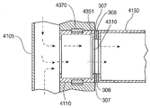
도 43b 에 도시된 단면도의 조립체는 카트리지(4110)의 후방으로 공기가 유동하는 통로가 되는 공동 영역(void region)을 형성하는 평면형 시트 부재(4105)를 포함한다. 상기 카트리지는, 인접한 카트리지와의 밀봉을 형성하는데에 도움이 되도록 제공된 탄성 재료로 이루어진 상부 밀봉 부재(4370)를 포함한다. 공기 유동은 부재(4351)에 의해 간섭을 받을 수 있으며, 부재(4351)는 공기가 서버(4150) 안으로 유동함을 허용하는 통로(4310)를 개방 및 폐쇄하기 위해 슬라이딩할 수 있다. 레일 부재는 2 부분 부재(307, 308)로서 도시되어 있는바, 2 부분 부재를 통해서는 카트리지(4110)로부터 서버(4150)로 공기가 유동함을 허용하는 통로가 제공되어 있다.43B includes a
도 43c 에는 도 43b 에서 계속되는 다른 실시예가 도시되어 있는바, 이것은 고리형 밀봉 링 부재(4398)를 포함한다. 이 실시예에서는, 공기 통로들의 연결부분(junction)에 제공되어 있는 고리형 링(4399)으로부터 고리형 직물 쉬라우드(annular fabric shroud)가 축방향으로 연장되고, 쉬라우드(4399)는 공기 유동에 응답하여 부품들 사이의 연결부분을 밀봉하도록 반경방향으로 변위된다. 이와 같은 구성으로 인하여, 공기가 유동하는 때에는 상기 쉬라우드가 카트리지, 레일, 및 서버 사이의 간극을 채운다.Fig. 43c shows another embodiment that follows from Fig. 43b, which includes an annular
도 43d 는 도 43c 및 도 43b 로부터 계속되는 것으로서, 여기에는 서버(4150)로부터 후방 패널로의 공기 유동이 개략적으로 도시되어 있다. 도 43c 에 도시된 실시예에서와 유사하게, 본 실시예는 고리형 밀봉 부재(4388) 및 쉬라우드 부재(4389)를 포함하고, 상기 휘라우드는 공기 유동에 응답하여 변위됨으로써 서버(4150), 레일 부재들(307, 308), 및 카트리지(4162) 간의 인터페이스를 통한 공기 손실을 최소화시킨다.43D continues from FIGS. 43C and 43B, in which the air flow from the
도 44 에 도시된 카트리지(4300)는 폐쇄 위치(4345)에 있고 부재(4380)는 후퇴 위치에 있는데, 여기에서 블록 부재(4330)는 통로들(4310, 4311, 4312, 4313)을 폐쇄하도록 움직여져 있으며, 핀들(4381, 4382)은 후퇴 위치에 있는 것으로 도시되어 있다. 본 실시예에서는, 예를 들어 밀봉 부재(4370)와 같은 밀봉 부재를 교번하여 상승 및 하강시키는 캠 부재의 회전에 의해서, 밀봉이 기계적으로 해제될 수 있다. 다른 대안적인 실시예에서는, 탄성 부재가 스프링 방식으로 편향되고 조립체에 대해 하방향으로 변위될 수 있도록 구성된다. 또 다른 실시예에서는, L자 형상의 개구를 통하여 접근가능한 스위치 연장부의 측방향 움직임에 의해서 상기 탄성 부재를 기계적으로 잠그고 상승시키는 기계적 스위치가 제공된다. 도 45 에는, 직립 부재(4521)와 직립 부재(4520)에 걸쳐서 복수의 카트리지, 예를 들어 카트리지(4550, 4551)를 포함하는 측부 패널 조립체(4500)가 도시되어 있다. 상기 카트리지들의 후방 표면은 상기 패널의 내부 공동의 전방 표면을 형성한다. 상기 직립 부재(4521)에 인접하여 위치한 직립 전방 포스트 부재(upright front post member; 4575)는 상기 장치의 레일들과 서버들을 지지하기 위하여 제공된다.The
도 46 에 도시된 완전히 조립된 전방 패널은 측부 패널 조립체(4500), 직립 전방 포스트 부재(4575), 및 카트리지들(4558, 4559, 4560)을 포함한다. 도 47 에 도시된 대안적인 조립체는 밸브들 및 통로들이 없는 다수의 카트리지(4840)들을 포함한다. 도 48 에는 다른 대안적인 조립체가 도시되어 있는바, 여기에서의 카트리지(4840)들은 밸브 또는 통로를 포함하지 않도록 선택되어 있다. 따라서 도 47 및 도 48 에는, 본 발명에서 사용될 수 있는 블랭크 카트리지(4720)을 포함하는, 카트리지들(4750, 4730, 4710)의 대안적인 구성형태가 도시되어 있다. 도 47 에 도시된 바와 같이, 카트리지들은 서버의 수직 치수에 맞는 다양한 수직 치수를 가질 수 있다. 또한 본 실시예의 카트리지들은 다양한 서버 및 네트워크 장비의 필요에 부합하는, 아이리스 밸브 및 통로의 다양한 측방향 배치를 가질 수 있다.The fully assembled front panel shown in Figure 46 includes a
도 49 에는 쿼터 패널들(4950, 4951, 4952, 4953) 내에 장착된 단일 랙 유닛 서버(4905)들이 충만하게 구비된 서버 조립체(4900)가 도시되어 있다.49 shows a
도 50 에 도시된 서버 랙 조립체 및 서버들은 선택에 따라서 캐비넷(5000) 안에 넣어지는데, 상기 캐비넷은 측부 외부 패널들(5005, 5006), 상부 외부 패널(5025), 및 저부 외부 패널(5008)을 포함한다. 쿼터 패널들(5010, 5011, 5012, 5013) 모두는 중간 프레임에 결합되어 충만하게 지지된다. 랙 전체는 다리부들(5020, 5021, 5022)에 의하여, 또는 대안적으로는 캐니스터(caster)들에 의하여 지지 표면으로부터 높은 위치에 놓인다. 상부 패널에는, 외부 패널들 안에 수납되는 후방 패널(5010)과 전방 패널(5012)로의 공기 유동을 허용하는 통로들이 제공된다. 도시되지는 않았으나, 전력 케이블, 네트워크 케이블, 및 다른 케이블을 위하여 구성요소(5008, 5025)에 추가적인 통로들이 추가될 수 있다.The server rack assembly and servers shown in FIG. 50 are optionally housed in a
도 51 에 도시된 조립된 랙 시스템(5100)은 서버(5170)들을 유지하는 측부 전방 패널들 및 후방 측부 패널들을 덮는 외부 측부 커버들(5008, 5009)을 포함한다.The assembled
본 실시예에서는 랙 전체를 폐쇄하고 잠그기 위하여 사용될 수 있는 전방 및 후방 도어들이 제공된다. 다른 실시예에서는, 사용되는 패널들이 절연될 수 있다. 다시 도 51 을 참조하면, 상기 장치의 상부에는 전방 측방 측부 패널들과 소통되는 전방 상부 (흡입) 통로들(5121, 5130)이 구비되어 있다 (배출 통로들(5125, 5135)도 도시되어 있음). 유입 통로들(5121, 5130)의 옆에는 압력 해제 밸브들(5128, 5131)이 있다. 상기 시스템 내의 압력이 미리 정해진 압력을 초과하는 때에는, 상기 밸브들이 공기를 대기 중으로 해제시킴으로써 시스템의 부품들에 대한 손상을 방지한다. 유사한 압력 해제 밸브들(5138, 5142)이 후방 패널에 위치한다. 상기 패널의 상부에는 와이어(5140)들을 거쳐서 카트리지들과 교신하는 콘트롤러(5150)가 위치한다.In this embodiment, front and rear doors are provided that can be used to close and lock the entire rack. In other embodiments, the panels used can be insulated. 51, upper portions of the apparatus are provided with front upper (intake)
도 52 에는 랙 장치(5200)의 평면도가 도시되어 있는바, 상기 랙 장치는 공기 조화기(5204)를 포함하고, 이 공기 조화기는 도관들(5220, 5223)을 통하여 전방 패널들에 있는 상부 유입 통로들로 찬 공기를 제공한다. 공기가 서버를 통과한 다음에는 후방 패널들로 유동하고, 상부 통로들(5282, 5285)을 통해 이탈할 수 있다. 상기 패널들로부터 나온 공기는 도관(5228)들을 통해서 펌프(5229)로 보내지고, 상기 펌프는 배출 시스템 내의 음압을 유지하고 공기를 전방 패널들로부터 서버들을 거쳐서 후방 패널들로 이동시킨다. 상기 펌프로부터의 공기는 상기 시스템을 통하는 순환을 위한 통로들(미도시)을 통해서 공기 조화기로 되돌려 전달될 수 있다. 또한 (도 51 의 콘트롤러(5150)와 동일한) 콘트롤러(5050)도 도시되어 있다.52 shows a top view of the
도 53 에는 랙 시스템(5300)의 저부 표면(5310)이 조화기(5340)로부터의 찬 공기를 도관(5325)들로부터 받아들이는 모습이 도시되어 있다. 공기는 도관들(5329, 5330)을 통해서 상기 시스템으로부터 배출된다. 상기 배출 공기 유동 시스템 내의 음압을 생성 및 유지시키는 펌프(5345)가 제공되는바, 이것은 (도시되지 않은) 통로들을 통해서 공기를 공기 조화기로 되돌려 전달할 수 있다.Figure 53 illustrates the
본 실시예에서, 상기 시스템은 서버 또는 서버들의 그룹의 온도에 따라서 유동 파라미터들을 조절할 수 있는 서보 모터 및 콘트롤러를 포함한다. 다른 실시예에서 상기 시스템은 제어 보드를 포함하는데, 상기 제어 보드는 서버들, 밸브 콘트롤러, 공기 조화기, 히트 펌프, 및 원격 중앙 모니터링 및 제어 장소와의 교신을 위한 이더넷 통신 포트가 제공되어 있는 소형 회로 보드를 포함한다.In the present embodiment, the system includes a servo motor and a controller capable of adjusting the flow parameters according to the temperature of the server or group of servers. In another embodiment, the system includes a control board, which includes a server, a valve controller, an air conditioner, a heat pump, and a miniature microcomputer equipped with an Ethernet communication port for communication with a remote central monitoring and control station Circuit board.
도 54 에 도시된 다른 실시예(5400)에서, 공기는 유연성 튜브형 부재들(5420, 5421, 5422)을 이용하여 카트리지 부재(5410)으로부터 서버(5415)의 전방 패널(5412)에 제공된 개구들로 보내진다. 이 도면에는 여기에서 설명된 카트리지들을 수용하는 패널들(5428, 5429)이 포함되어 있다. 도 55 에는 도 54 를 참조하여 전술된 시스템(5400)의 평면도가 도시되어 있으며, 여기에는 서버(5417)의 전방 가장자리를 지나 연장되는 유연성 튜브들(5420, 5421, 5422)이 도시되어 있다.In another
도 56 에 도시된 본 발명의 다른 실시예에서, 공기는 카트리지 부재(5602)로부터 유연성 튜브형 부재들(5620, 5621, 5622)을 통하여 서버(5615)의 상부에 있는 개구들로 배분된다. 이 실시예에서, 서버(5615)는 서버 랙(5600)의 거리의 절반만큼만 연장된다. 또한 쿼터 패널들(5628, 5629)과 레일(5625)이 도시되어 있다. 도 56 에 도시된 실시예의 평면도가 도시되어 있는 도 57 에는 측방 패널(5627)로부터 서버(5615)의 상부로 연장되어 있는 도관들이 도시되어 있다. 도 58 에는 본 발명의 다른 일 형태가 도시되어 있는데, 여기에서 공기는 유연성 호스 또는 튜브형 부재를 이용하여 서버(5905)의 후방으로부터 후방 패널(5908)에 있는 카트리지(5930)로 배출 또는 제거된다. 도 59 에 도시된 바와 같이, 공기는 튜브형 부재들(5917, 5916, 5915)을 이용하여 서버(5905)로부터 후방 패널 섹션(5908)으로 보내진다.56, air is distributed from the cartridge member 5602 through the flexible
도 60 에는 본 발명의 다른 실시예에 따른 대안적인 공기 유동 구조(6000)의 개략도가 도시되어 있다. 이 실시예에서 서버들(6011, 6012)은 동일한 수직 위치에 결합되고, 그 수직 위치는 전방 측부 패널(6005)와 후방 측부 패널(6006)에 위치한다. 서버들(6010, 6009)은 통상적인 랙 장착 하드웨어를 이용하여 대응되는 전방 측부 패널(6005)와 대응되는 후방 측부 패널(6006)에 결합된다. 상기 전방 패널(6005)와 후방 패널(6006)에 제공된 카트리지들로부터의 공기는 측방향으로 유동하여 서버들(6009, 6010, 6011, 6012) 안으로 진행하고, 개구들, 예를 들어 개구들(6025, 6076, 6027, 6078)을 통해서 서버들로부터 나온다. 상기 개구들은 서버들의 대향된 측부들에 있으며, 패널들(6005, 6006)의 반대측에 있는 (도시되지 않은) 측방 패널들에 제공되어 있는 (도시되지 않은) 카트리지들의 통로들은 서버들로부터 공기를 수용하여 그 공기를 패널들 밖으로 배분한다.60 is a schematic diagram of an
도 61 에는 종래 기술의 블레이드 서버 시스템(6100)이 도시되어 있는바, 여기에서 복수의 블레이드 서버들(6121, 6122, 6123, 6124, 6125, 6126, 6127, 6128)은 수직 방위의 자세를 가지며 외부 하우징(6110) 내에 수납된다. 외부 하우징(6110)은 서버 랙 안에 수용되도록 설계된다. 도 62 에는 다른 대안적인 실시예가 도시되어 있는데, 여기에서 외부 하우징(6120)은 복수의 서버들, 예를 들어 서버들(6221, 6222)을 에워싼다. 블레이드 서버 시스템(6200)은 2 열의 수직 방위를 가진 서버들을 포함한다. 도 63 에는 본 발명의 일 실시예가 도시되어 있는바, 이것은 수직 방위를 갖는 블레이드 서버들로 찬 공기를 제공하고 그 블레이드 서버로부터 공기를 제거하도록 구성된다. 여기에서, 도관(6320)은 전술된 본 발명의 실시예들 중 하나에 따른 카트리지에 연결되고, 공기를 서버(6301)의 상부 표면에 제공된 개구로 지향시킨다. 공기는 중공 튜브형 도관(6328)을 이용하여 서버(6301)로부터 제거되는바, 상기 중공 튜브형 도관(6328)은 공기를 전술된 후방 측방 패널에 제공된 카트리지로 보낸다. 도 63 에 도시된 서버 장치(6300)에서는, 서버들(6301, 6302, 6303, 6304, 6307, 6308, 6309, 6310) 각각에서 서버로의 공기 유동과 서버로부터의 공기 유동이 제공된다. 도관들, 예를 들어 흡입 도관들(6320 내지 6327) 및 배출 도관들(6328 내지 6335)은 서버를 보유하는 외부 케이싱(6340)을 통과하여 공기를 측방향으로 지향시킨다.61 shows a prior art
도 64 에 도시된 다른 실시예(6400)에서, 중공 튜브형 냉각 도관들, 예를 들어 도관들(6420, 6421)은 서버들(6401, 6402) 안으로 기류를 제공한다. 공기는 위에서 실시예(6300)와 관련하여 도시 및 설명된 바와 유사한 방식으로 상기 서버들로부터 제거된다. 서버(6342)들은 블레이드 샤시 구조 안에서 (수직 자세로) 외부 케이싱(6340) 안에 위치한다.64, the hollow tubular cooling conduits, for example,
도 65 에 도시된 블레이드 서버 구조(6500)에서, 공기는 서버들의 저부 표면들에 있는 개구들을 통해서 서버들로 배분되는바, 이것은 서버들에 연결된 튜브형 도관들(6530, 6531, 6532, 6533, 6534, 6535, 6536, 6537)을 통해 이루어진다. 공기는 튜브형 도관들(6538, 6539, 6540, 6541, 6542, 6543, 6544)을 이용하여 서버들로부터 제거되고 측방향으로 지향되는바, 여기에서 공기는 전술된 바와 같이 측방 패널들에 제공되어 있는 카트리지 부재들에 의해 수용된다. 도 66 에 도시된 다른 실시예(6600)에서, 일 열의 블레이드 서버들은 수직 자세를 가진 복수 열의 서버들을 포함한다. 공기는 튜브형 도관들, 예를 들어 튜브형 도관들(6630, 6631)을 이용하여 하측 열에서 서버들로 제공된다. 이 도관들은 장치(6600)의 측방 측부들로부터 공기 유동을 제공하고, 공기를 서버들의 저부 표면으로 전달한다. 공기는 유사한 도관들을 이용하여 서버들로부터 제거되고 측방향으로 지향된다. 서버(6501)들은 도 66 의 케이싱(6340, 6642) 내에 수직으로 배치된다.In the
(도시되지 않은) 다른 실시예에서는 카트리지들에 팬(fan)들이 제공되어서 서버들로의 공기 유동을 돕고 서버들로부터의 공기의 제거를 돕는다. 또 다른 실시예에서는 상기 팬들이 패널들에 있는 흡입 개구들 및 배출 개구들과 연계되어 제공되거나, 또는 상기 패널들로 그리고 상기 패널들로부터의 공기 취급을 제공하는 도관들을 따라서 제공된다.In other embodiments (not shown), fans are provided in the cartridges to assist air flow to the servers and to help remove air from the servers. In another embodiment, the fans are provided in association with suction openings and discharge openings in the panels, or along conduits that provide air handling to and from the panels.
도 67 에는 일 실시예의 개략도가 도시되어 있는바, 여기에서는 복수의 랙(6705)들이 빌딩 구조물(6701) 안에 배치되어 서버 시설 또는 데이터 센터를 이룬다. 데이터 센터는, 상기 데이터 센터에 인접하거나 또는 원격 교신으로 통신할 수 있는 중앙 콘트롤러(6730)를 포함한다. 이 시스템은 선택에 따라서, 공기 조화 시스템을 포함하는데, 이것은 압축기, 응축기 요소, 및 팬과 같은 통상적인 외부 부품(6710)들과, 상기 시스템에서 사용되는 냉각제를 위한 팽창 장치, 증발 코일들, 및 팬들을 포함하는 내부 부품(6711)들을 포함한다. 또한 상기 시스템은 송풍기, 팽창 장치, 및 외부 코일을 포함할 수 있는 내부 부품(6721)들(미도시)과, 압축기, 체크 밸브들, 팽창 장치, 외부 코일들, 및 팬을 포함하는 통상적인 외부 부품(6720)들을 포함하는 히트 펌프 기술을 채택한 것일 수도 있다.67 is a schematic diagram of one embodiment in which a plurality of
또 다른 실시예에서는 다양한 서버 모델들의 수용을 위하여 상기 랙 시스템과 연계된 다양한 레일 부재들이 제공되는데, 여기에서 상기 레일들은 다양한 서버들에 있는 통로들에 맞는 다양한 통로들을 구비한 다양한 설계형태를 가진다.In another embodiment, various rail members associated with the rack system are provided for accommodating various server models, wherein the rails have various designs with various passageways for the passageways in the various servers.
본 발명의 실시예들의 구조 및 기능에 관한 상세 설명과 함께 다양한 특징들 및 장점들이 상세히 설명되었으나, 상기 설명은 예시를 위한 것일 뿐으로서, 본 발명의 원리 내에서 상세 사항들, 특히 구성요소들의 형상, 크기, 및 배치의 면에서 그리고 상기 설명은 첨부된 청구범위에 기재된 용어들의 일반적이고 넓은 의미에 의하여 정해지는 최대한의 범위 내에서 변형이 가해질 수 있다는 점이 이해되어야 할 것이다.Although the various features and advantages have been described in detail in the detailed description of the structure and function of the embodiments of the present invention, the description is for illustrative purposes only and is not intended to limit the scope of the present invention, Size, and arrangement of the features disclosed herein, and that the description may be modified within the full scope of the general and broad meaning of the terms in the appended claims.
본 발명은 특정의 바람직한 형태를 참조하여 상당히 상세히 설명되었으나, 본 기술분야에서 통상의 지식을 가진 자는 이로부터 다른 자명한 형태를 용이하게 도출할 수 있을 것이다. 따라서, 첨부된 청구범위의 취지 및 범위는 여기에서 설명된 특정 형태에 관한 설명에 국한되지 않는다.While the present invention has been described in considerable detail with reference to certain preferred embodiments thereof, those skilled in the art will readily conceive other obvious forms thereof. Accordingly, the spirit and scope of the appended claims are not intended to be limited to the description of the specific forms set forth herein.
[산업상 이용가능성][Industrial applicability]
본 발명에 의하면, 컴퓨터 장비, 특히 포위된 공간 안에 넣어진 집합적인 컴퓨터 장비의 효율적인 냉각이 가능하게 된다. 서버 팜(server farm), 코-로케이션(co-location) 시설, 및 기타 계산 및 저장 가능성을 제공함에 특화되어 있는 데이터 센터의 전력 사용은, 가용 전기의 꽤 큰 비중을 이용한다. 이와 같은 전력 사용의 대부분은 컴퓨터 장비의 작동 뿐만이 아니라 컴퓨터 장비의 냉각과 관련된 것이다. 본 발명은 상기 시설들에 대한 실질적인 변형을 필요로 하지 않으면서도 이와 같은 장비의 냉각 효과를 실질적으로 향상시키며, 또한 모듈형이고 업그레이드가능한 해결 방안을 제시한다.According to the present invention, efficient cooling of computer equipment, especially collective computer equipment enclosed in an enclosed space, is enabled. Data center power usage, which is specialized in providing server farms, co-location facilities, and other computing and storage possibilities, takes advantage of a fairly large portion of available electricity. Much of this power usage is related to the cooling of computer equipment as well as the operation of computer equipment. The present invention substantially improves the cooling effect of such equipment without requiring substantial modifications to the facilities, and presents a modular and upgradeable solution.
Claims (26)
포위된 빌딩 내부를 한정하는 빌딩으로서, 상기 빌딩 내에서의 기체의 밀봉된 이동을 위한 빌딩 유입 도관(building inlet conduit) 및 기체를 열원(熱源; heat reservoir)으로 배출하기 위한 유출 도관을 구비한, 빌딩;
측방 지지 부재들을 포함하는 서버 랙 스탠드(server rack stand)로서, 상기 측방 지지 부재들은 내부 공동(interior void), 상기 빌딩 유입 도관과 유체소통(fluid communication)되는 기류 유입 통로, 및 상기 빌딩 유출 도관과 유체소통되는 기류 유출 통로를 한정하는, 서버 랙 스탠드;
상기 서버 랙 스탠드의 측방 지지 부재들 사이에서 분리가능하게 고정되도록 구성되고 실질적으로 밀봉된 컴퓨터로서, 상기 고정시 상기 기류 유입 통로 및 상기 기류 유출 통로와 개별적으로 인접하게 위치되는 치수를 가진 기류 유입 개구 및 기류 유출 개구를 한정하는 케이스(case)를 구비한, 컴퓨터;
상기 기류 유입 개구와 상기 기류 유입 통로 사이, 그리고 상기 기류 유출 개구와 상기 기류 유출 통로 사이에 밀봉 연결부(sealed connection)를 형성하는 서버 도관(server conduit); 및
공기를 상기 빌딩 유입 도관으로부터 상기 열원까지 강제로 진행시키기 위한 기류 소스(airflow source);를 포함하는, 서버 시설.A server facility, said server facility comprising:
A building defining an enclosed building comprising a building inlet conduit for the sealed movement of the gas in the building and an outlet conduit for discharging the gas into a heat reservoir, building;
A server rack stand comprising side support members, the side support members comprising an interior void, an air flow inlet channel in fluid communication with the building inlet conduit, A server rack stand defining the airflow outlet passage in fluid communication;
A substantially enclosed computer configured to be releasably secured between side support members of the server rack stand, the airflow inflow opening having a dimension positioned separately adjacent to the airflow inflow passage and the airflow outflow passage at the time of fixation, And a case defining a flow-out opening;
A server conduit defining a sealed connection between the air inlet opening and the air inlet opening, and between the air outlet opening and the air outlet opening; And
And an airflow source for forcing the air to flow from the building inlet conduit to the heat source.
상기 서버 랙 스탠드는, 상기 내부 공동을 한정하는 패널, 한 쌍의 주변 포스트(peripheral post)들, 및 상기 측방 지지 부재들 사이에 분리가능하게 배치되어 상기 기류 유출 통로와 상기 서버 랙 공동의 측벽을 한정하는 적어도 하나의 카트리지(cartridge)를 포함하는, 서버 시설.The method according to claim 1,
The server rack stand includes a panel defining the interior cavity, a pair of peripheral posts, and a side wall separably disposed between the side support members to define a side wall of the airflow outlet and the server rack cavity Wherein the at least one cartridge defines at least one cartridge.
상기 서버 랙 스탠드는 중공 챔버(hollow chamber)를 한정하는 측방 포스트들을 포함하고, 상기 측방 포스트들 내부에서 상기 중공 챔버는 상기 빌딩 유입 도관 및 상기 스탠드 내부 공동과 유체소통되는, 서버 시설.3. The method of claim 2,
Wherein the server rack stand includes lateral posts defining a hollow chamber within which the hollow chamber is in fluid communication with the building inlet conduit and the interior of the stand.
상기 스탠드에 포함되는 상기 공동 측벽(void sidewall)은 복수개의 상기 카트리지로 이루어진, 서버 시설.3. The method of claim 2,
Wherein the void sidewall included in the stand comprises a plurality of the cartridges.
상기 카트리지들은 상기 스탠드 공동으로부터 상기 케이스 안으로의 기류를 막도록 구성된 장애물(impediment)을 포함하고, 상기 장애물은 선택적으로 작동가능한, 서버 시설.3. The method of claim 2,
Said cartridges comprising an impediment configured to block airflow from said stand cavity into said case, said obstruction being selectively operable.
상기 서버 시설은 상기 컴퓨터를 상기 카트리지에 고정시키는 스탠드 레일(stand rail)을 더 포함하고, 상기 스탠드 레일은 (i) 상기 기류 유입 개구 및 상기 기류 유출 개구 중 적어도 하나와, (ii) 상기 기류 유입 통로 및 상기 기류 유출 통로 중 적어도 하나를 포함하는 두 가지 모두에 대응되는 레일 통로들을 포함하는, 서버 시설.6. The method of claim 5,
Wherein said server facility further comprises a stand rail for securing said computer to said cartridge, said stand rail comprising: (i) at least one of said air flow inlet and said air flow outlet opening; (ii) And a rail passage corresponding to both, including at least one of the passageway and the airflow outlet passageway.
상기 서버 시설은, 상기 장애물과 전기적으로 교신하는 온도 센서를 더 포함하고, 상기 온도에 기초하여 상기 장애물을 작동시키는, 서버 시설.6. The method of claim 5,
Wherein the server facility further comprises a temperature sensor in electrical communication with the obstacle and operates the obstacle based on the temperature.
상기 랙 스탠드는 실질적으로 밀봉된 복수의 컴퓨터들을 지지하고, 상기 컴퓨터들 각각은 상기 서버 랙 스탠드의 측방 지지 부재들 사이에서 분리가능하게 고정되도록 구성되고 케이스를 구비하며, 상기 케이스에는 상기 고정시에 상기 기류 유입 통로와 상기 기류 유출 통로 각각에 근접하여 위치되는 치수를 가진 상기 기류 유입 개구 및 상기 기류 유출 개구가 형성되어 있는, 서버 시설.8. The method of claim 7,
Wherein the rack stand supports a plurality of substantially enclosed computers, each of the computers being configured to be releasably secured between lateral support members of the server rack stand and having a case, And the airflow inlet and the airflow outlet opening having a size positioned adjacent to each of the airflow inlet passage and the airflow outlet passage are formed.
상기 열원은 상기 기류 소스와 유체소통되는, 서버 시설.The method according to claim 1,
Wherein the heat source is in fluid communication with the airflow source.
상기 기류 소스는 저온 소스(cold source)와 유체소통되는, 서버 시설.10. The method of claim 9,
Wherein the airflow source is in fluid communication with a cold source.
상기 열원은, 가열된 기체를 상기 빌딩 외부로 배기시키기 위한 빌딩 배출부와 유체소통되는, 서버 시설.The method according to claim 1,
Wherein the heat source is in fluid communication with a building discharge for venting heated gas out of the building.
컴퓨터들을 수용하는 빌딩 안에서 공기를 기류 소스로부터 강제로 진행시키는, 강제 진행 단계;
밀봉된 빌딩 도관 안에서 기류를 중공형의(hollow) 서버 스탠드 부분(server stand portion)의 유입 챔버(influx chamber)안으로 전달하는 단계로서, 상기 서버 스탠드는 상기 컴퓨터들 중 적어도 하나를 지지하는, 전달 단계;
상기 유입 챔버로부터 서버 도관을 통하여 상기 컴퓨터의 밀봉된 케이스 안으로 기류를 지향시키는, 지향 단계; 및
상기 컴퓨터의 케이스로부터의 기류를 상기 빌딩 도관을 통하여 상기 스탠드 부분의 외부에 있는 열원으로 이동시키는, 이동 단계;를 포함하는, 컴퓨터 장비 냉각 방법.A method for cooling computer equipment, the method comprising:
Forcing air from an airflow source in a building housing the computers;
Delivering airflow in a sealed building conduit into an influx chamber of a hollow server stand portion, the server stand supporting at least one of the computers, ;
Directing airflow from the inlet chamber through the server conduit into the sealed case of the computer; And
And moving the airflow from the case of the computer through the building conduit to a heat source external to the stand portion.
상기 컴퓨터 장비 냉각 방법은 기류를 상기 컴퓨터 케이스로부터 상기 중공형 서버 스탠드 부분의 이탈 챔버(exodus chamber) 안으로 이송하는 이송 단계를 더 포함하고, 상기 지향 단계는 기류를 상기 이탈 챔버로부터 상기 열원으로 지향시킴을 포함하는, 컴퓨터 장비 냉각 방법.13. The method of claim 12,
Wherein the computer equipment cooling method further comprises a transfer step of transferring airflow from the computer case into an exodus chamber of the hollow server stand portion, the directing step directing airflow from the exit chamber to the heat source The method comprising the steps of:
상기 컴퓨터 장비 냉각 방법은 기류를 상기 컴퓨터 케이스로부터 보충적 중공형 서버 스탠드 부분의 이탈 챔버로 이송하는 단계를 더 포함하고, 상기 지향 단계는 기류를 상기 이탈 챔버로부터 상기 열원으로 지향시킴을 포함하는, 컴퓨터 장비 냉각 방법.14. The method of claim 13,
Wherein the computer equipment cooling method further comprises transferring airflow from the computer case to a desorption chamber of the supplemental hollow server stand portion, the directing step directing airflow from the desorption chamber to the heat source. How to cool the equipment.
상기 컴퓨터 장비 냉각 방법은 복수의 스탠드 카트리지들로부터 상기 이탈 챔버를 구성하는 단계를 더 포함하고, 상기 카트리지들 각각은 상기 유입 챔버의 측벽 및 상기 서버 도관 모두를 형성하는, 컴퓨터 장비 냉각 방법.15. The method of claim 14,
Wherein the computer equipment cooling method further comprises configuring the departure chamber from a plurality of stand cartridges, each of the cartridges forming both a side wall of the inlet chamber and the server conduit.
상기 컴퓨터 장비 냉각 방법은 복수의 스탠드 카트리지들로부터 상기 유입 챔버를 구성하는 단계를 더 포함하고, 상기 카트리지들 각각은 상기 유입 챔버의 측벽 및 상기 서버 도관 모두를 형성하는, 컴퓨터 장비 냉각 방법.15. The method of claim 14,
Wherein the computer equipment cooling method further comprises configuring the inlet chamber from a plurality of stand cartridges, each of the cartridges forming both a side wall of the inlet chamber and the server conduit.
상기 지향 단계는, 상기 서버 도관을 선택적으로 막는 장애물을 작동시킴으로써, 기류를 상기 유입 챔버로부터 상기 컴퓨터의 상기 밀봉된 케이스로 지향시킴을 포함하는, 컴퓨터 장비 냉각 방법.13. The method of claim 12,
Wherein the directing step comprises directing an airflow from the inlet chamber to the sealed case of the computer by actuating an obstruction selectively blocking the server conduit.
상기 이동 단계는 기류를 상기 컴퓨터 케이스로부터 상기 빌딩 도관을 통하여, 상기 기류 소스와 유체소통되는 열원으로 이동시킴을 포함하는, 컴퓨터 장비 냉각 방법.13. The method of claim 12,
Wherein the moving comprises moving airflow from the computer case through the building conduit to a heat source in fluid communication with the airflow source.
상기 이동 단계는 기류를 상기 컴퓨터 케이스로부터 상기 빌딩 도관을 통하여, 가열된 기체를 상기 빌딩 외부로 배출시키기 위해 상기 빌딩의 외부와 유체소통되는 열원으로 이동시킴을 포함하는, 컴퓨터 장비 냉각 방법.13. The method of claim 12,
Wherein the moving comprises moving airflow from the computer case through the building conduit to a heat source in fluid communication with the exterior of the building to discharge heated gas out of the building.
포스트 높이(post height)를 가지며 중앙 지원 공동(central support void)을 한정하는 수직 지지 포스트(vertical support post)들로서, 실질적으로 밀봉된 내부 공동(interior cavity), 및 상기 중앙 지원 공동을 향하여 지향된 제1 개구와 제2 개구를 한정하는 표면을 포함하는, 수직 지지 포스트들;
상기 제2 개구와 유체소통되는 기류 도관; 및
상기 포스트 높이의 절반보다 작은 카트리지 높이를 가지며 상기 포스트들 사이에서 상기 포스트들에 밀봉방식으로 고정되는 적어도 하나의 카트리지로서, 포스트에 대한 컴퓨터의 측방 고정을 지원하도록 구성되고, 상기 제1 개구와 상기 중앙 지원 공동의 주변 경계를 한정하는, 적어도 하나의 카트리지;를 포함하는, 서버 랙 스탠드 부분.As a server rack stand part,
A vertical support post, having a post height and defining a central support void, comprising a substantially sealed interior cavity, and a longitudinally directed, Vertical support posts, including a surface defining a first opening and a second opening;
An air flow conduit in fluid communication with said second opening; And
At least one cartridge having a cartridge height less than half of the post height and secured in a sealed manner to the posts between the posts, the cartridge being configured to support lateral locking of the computer relative to the posts, And at least one cartridge defining a circumferential boundary of the central support cavity.
상기 서버 랙 스탠드 부분은 상기 내부 공동을 한정하는 패널 및 한 쌍의 주변 포스트를 포함하고, 상기 카트리지는 상기 포스트들 사이에 분리가능하게 배치되도록 구성되며, 상기 카트리지는 상기 제1 개구 및 상기 중앙 지원 공동의 측벽을 한정하는, 서버 랙 스탠드 부분.21. The method of claim 20,
Wherein the server rack stand portion includes a panel defining the interior cavity and a pair of peripheral posts, the cartridge being configured to be removably disposed between the posts, the cartridge having a first opening and a central support A server rack stand portion defining a cavity sidewall.
상기 서버 랙 스탠드 부분은, 상기 중앙 지원 공동을 밀봉하도록 상기 중앙 지원 공동에 걸쳐있는 복수의 카트리지들을 포함하는, 서버 랙 스탠드 부분.22. The method of claim 21,
Wherein the server rack stand portion includes a plurality of cartridges spanning the central support cavity to seal the central support cavity.
상기 서버 랙 스탠드 부분은, 상기 카트리지들과 동등한 치수를 가지고 또한 밀봉된 측방 표면을 가진 복수의 블랭크(blank)들을 포함하는, 서버 랙 스탠드 부분.23. The method of claim 22,
Wherein the server rack stand portion includes a plurality of blanks of equivalent dimensions to the cartridges and having a sealed side surface.
상기 중앙 지원 공동은 복수의 카트리지들에 의해 실질적으로 밀봉되어 상기 제2 개구로부터 상기 제1 개구로의 기류의 통행을 위한 기체 유입 챔버를 형성하는, 서버 랙 스탠드 부분.21. The method of claim 20,
Wherein the central support cavity is substantially sealed by a plurality of cartridges to form a gas inlet chamber for passage of airflow from the second opening to the first opening.
상기 지지 포스트는 보충적 중앙 지원 공동을 더 형성하고, 상기 표면은 상기 공동을 향하여 지향된 제3 개구 및 제4 개구를 한정하며, 상기 보충적 중앙 지원 공동은 복수의 카트리지들에 의해 실질적으로 밀봉되어 상기 제3 개구로부터 상기 제4 개구로의 기류의 통행을 위한 기체 이탈 챔버를 형성하는, 서버 랙 스탠드 부분.25. The method of claim 24,
Wherein the support post further defines a complementary central support cavity, the surface defining a third opening and a fourth opening directed toward the cavity, the supplemental central support cavity being substantially sealed by the plurality of cartridges, And a gas release chamber for passage of airflow from the third opening to the fourth opening.
상기 랙 스탠드는 포스트 높이를 갖는 보충적 수직 지지 포스트들을 더 포함하고, 상기 보충적 수직 지지 포스트들은 보충적 중앙 지원 공동을 한정하며,
상기 포스트들은, 실질적으로 밀봉된 내부 보충 공동과, 상기 공동을 향하여 지향된 제3 개구 및 제4 개구를 한정하는 표면을 포함하며,
상기 보충적 중앙 지원 공동은 복수의 카트리지들에 의해 실질적으로 밀봉되어 상기 제3 개구로부터 상기 제4 개구로의 기류의 통행을 위한 기체 이탈 챔버를 형성하는, 랙 스탠드.A rack stand including the server rack stand portion of claim 24,
The rack stand further includes supplementary vertical support posts having a post height, the supplementary vertical support posts defining a supplemental central support cavity,
The posts comprising a substantially sealed inner replenishing cavity and a surface defining a third opening and a fourth opening directed toward the cavity,
Wherein said supplemental central support cavity is substantially sealed by a plurality of cartridges to form a gas release chamber for passage of airflow from said third aperture to said fourth aperture.
Applications Claiming Priority (3)
| Application Number | Priority Date | Filing Date | Title |
|---|---|---|---|
| US201562158529P | 2015-05-07 | 2015-05-07 | |
| US62/158,529 | 2015-05-07 | ||
| PCT/US2016/031516 WO2016179597A1 (en) | 2015-05-07 | 2016-05-09 | Computer server heat regulation utilizing integrated precision air flow |
Publications (2)
| Publication Number | Publication Date |
|---|---|
| KR20170142203A KR20170142203A (en) | 2017-12-27 |
| KR101907340B1 true KR101907340B1 (en) | 2018-10-11 |
Family
ID=57218351
Family Applications (3)
| Application Number | Title | Priority Date | Filing Date |
|---|---|---|---|
| KR1020177035419A Active KR101907340B1 (en) | 2015-05-07 | 2016-05-09 | Computer server thermal control using integrated precision airflow |
| KR1020197011323A Active KR102194228B1 (en) | 2015-05-07 | 2017-10-27 | Computer server heat conditioning with integrated precision airflow |
| KR1020207021263A Active KR102248648B1 (en) | 2015-05-07 | 2017-10-27 | Computer server heat regulation utilizing integrated precision airflow |
Family Applications After (2)
| Application Number | Title | Priority Date | Filing Date |
|---|---|---|---|
| KR1020197011323A Active KR102194228B1 (en) | 2015-05-07 | 2017-10-27 | Computer server heat conditioning with integrated precision airflow |
| KR1020207021263A Active KR102248648B1 (en) | 2015-05-07 | 2017-10-27 | Computer server heat regulation utilizing integrated precision airflow |
Country Status (8)
| Country | Link |
|---|---|
| US (24) | US9832912B2 (en) |
| EP (2) | EP3292745B1 (en) |
| JP (2) | JP6716685B2 (en) |
| KR (3) | KR101907340B1 (en) |
| CN (4) | CN107710894B (en) |
| AU (4) | AU2016258218B2 (en) |
| CA (3) | CA2985180C (en) |
| WO (2) | WO2016179597A1 (en) |
Families Citing this family (34)
| Publication number | Priority date | Publication date | Assignee | Title |
|---|---|---|---|---|
| US20220346281A1 (en) * | 2015-05-07 | 2022-10-27 | Edward Campbell Graff, JR. | Computer server heat regulation utilizing integrated precision air flow |
| US9832912B2 (en) * | 2015-05-07 | 2017-11-28 | Dhk Storage, Llc | Computer server heat regulation utilizing integrated precision air flow |
| CN108241412B (en) * | 2016-12-23 | 2020-11-20 | 鸿富锦精密电子(天津)有限公司 | Server rack |
| US10939587B2 (en) * | 2017-02-16 | 2021-03-02 | Dell Products, L.P. | System and method for injecting cooling air into servers in a server rack |
| US10524394B2 (en) * | 2017-05-08 | 2019-12-31 | Panduit Corp. | 4-post rack with integrated intake/exhaust regions |
| US10736241B1 (en) * | 2018-01-16 | 2020-08-04 | Amazon Technologies, Inc. | Temperature based pressure sensing and airflow control |
| US10398046B2 (en) * | 2018-01-30 | 2019-08-27 | Quanta Computer Inc. | Server rack with damping post |
| US11122713B1 (en) | 2018-06-21 | 2021-09-14 | Amazon Technologies, Inc. | Differential temperature based pressure sensing and airflow control |
| US10732681B2 (en) * | 2018-07-26 | 2020-08-04 | Microsoft Technology Licensing, Llc | Adaptive airflow guides in an electronic device |
| US11856724B2 (en) * | 2018-11-30 | 2023-12-26 | Ovh | System comprising a rack, with support members and components insertable in the rack and connectable via liquid connectors |
| EP4096379B1 (en) * | 2021-05-27 | 2026-01-07 | Ovh | System comprising a rack, with support members and components insertable in the rack and connectable via liquid connectors |
| EP3697183B1 (en) | 2019-02-13 | 2021-04-14 | Ovh | Rack adapted for receiving a component, system including the rack and the component and method of delivering power to a component mounted in a rack |
| KR102381692B1 (en) * | 2019-02-21 | 2022-03-31 | 주식회사 엘지에너지솔루션 | Battery rack and energy storage system comprising the same |
| US11558982B2 (en) * | 2019-05-30 | 2023-01-17 | Microsoft Technology Licensing, Llc | Slide rail as airflow channel |
| CN110799018B (en) * | 2019-10-28 | 2025-04-25 | 深圳市科信通信技术股份有限公司 | A wind energy cooling integrated cabinet |
| US11812575B2 (en) * | 2019-10-28 | 2023-11-07 | Chenbro Micom Co., Ltd. | Server system |
| US11558975B2 (en) * | 2019-10-28 | 2023-01-17 | Chenbro Micom Co., Ltd. | Server system |
| EP3817531B1 (en) * | 2019-10-28 | 2023-10-25 | Chenbro Micom Co., Ltd. | Server system |
| US11013151B1 (en) * | 2019-12-31 | 2021-05-18 | Quanta Computer Inc. | Electronic component housing cooling system |
| RU2763157C2 (en) * | 2020-02-14 | 2021-12-27 | Общество С Ограниченной Ответственностью «Яндекс» | Frame structure |
| TWM598581U (en) * | 2020-03-31 | 2020-07-11 | 銀欣科技股份有限公司 | Shell plate sound insulation structure |
| RU2764821C2 (en) * | 2020-06-01 | 2022-01-21 | Общество С Ограниченной Ответственностью «Яндекс» | Tray for electronic elements |
| US11533826B2 (en) * | 2020-06-11 | 2022-12-20 | Baidu Usa Llc | Air cooling system for component high dense clusters |
| DE102020120918A1 (en) * | 2020-08-07 | 2022-02-10 | Beckhoff Automation Gmbh | Control cabinet system with a base module and a function module, base module and function module |
| KR102392025B1 (en) * | 2021-07-19 | 2022-04-27 | 허봉수 | Prescription system by consultation process based on mobile app and construction method thereof |
| US12031780B2 (en) * | 2021-08-11 | 2024-07-09 | Hoffman Enclosures Inc. | Liquid manifold for electronics cabinet |
| KR102511222B1 (en) * | 2021-08-23 | 2023-03-17 | 주식회사 엄영대과학연구소 | AI-based learning services providing method and construction method thereof |
| KR102396259B1 (en) * | 2021-11-02 | 2022-05-09 | 유동표 | Providing method for building integrated system |
| KR102420803B1 (en) * | 2021-11-02 | 2022-07-13 | 유동표 | Construction method for building integrated system with increased ease of selection |
| US12386401B2 (en) * | 2022-01-11 | 2025-08-12 | Raytheon Company | Card cage system for hybrid cooling of computer circuit cards |
| US11895805B2 (en) * | 2022-02-14 | 2024-02-06 | Eagle Technology, Llc | Systems and methods for electronics cooling |
| CN115133869B (en) * | 2022-08-29 | 2022-11-08 | 福建德普柯发电设备有限公司 | Hybrid energy generating set |
| CN118510248B (en) * | 2024-07-17 | 2024-10-01 | 苏州元脑智能科技有限公司 | Server cabinet and control method thereof |
| CN120523302B (en) * | 2025-07-25 | 2025-09-19 | 苏州元脑智能科技有限公司 | Server cooling rack |
Citations (3)
| Publication number | Priority date | Publication date | Assignee | Title |
|---|---|---|---|---|
| US20030235025A1 (en) | 2000-07-19 | 2003-12-25 | Internet Research Institute, Inc. | Server unit comprising stacked multiple server unit cabinets accommodating multiple cartridge type server units |
| US20070205297A1 (en) | 2006-03-03 | 2007-09-06 | Finkam Joseph E | Methods and apparatuses for controlling air to a building |
| US20140071615A1 (en) | 2012-09-11 | 2014-03-13 | International Business Machines Corporation | Cooling host module |
Family Cites Families (180)
| Publication number | Priority date | Publication date | Assignee | Title |
|---|---|---|---|---|
| US3192306A (en) * | 1962-09-26 | 1965-06-29 | Philco Corp | Cooling wall structure for electronic equipment cabinet |
| US4535386A (en) | 1983-05-23 | 1985-08-13 | Allen-Bradley Company | Natural convection cooling system for electronic components |
| DE3585447D1 (en) | 1984-11-15 | 1992-04-02 | Fujitsu Ltd | COOLING STRUCTURE OF A RACK FOR ELECTRONIC DEVICES. |
| JPS61198799A (en) * | 1985-02-28 | 1986-09-03 | 株式会社東芝 | Connectable box construction |
| US4644443A (en) | 1985-09-27 | 1987-02-17 | Texas Instruments Incorporated | Computer cooling system using recycled coolant |
| US4672509A (en) | 1986-08-07 | 1987-06-09 | Ncr Corporation | Air cooling assembly in an electronic system enclosure |
| US4860163A (en) | 1988-08-05 | 1989-08-22 | American Telephone And Telegraph Company | Communication equipment cabinet cooling arrangement |
| US5216579A (en) * | 1992-01-29 | 1993-06-01 | International Business Machines Corporation | Rack based packaging system for computers with cable, cooling and power management module |
| US5287244A (en) | 1992-05-19 | 1994-02-15 | Sun Microsystems, Inc. | Computer housing with low noise cooling system |
| US5505533A (en) | 1994-01-10 | 1996-04-09 | Artecon | Rackmount for computer and mass storage enclosure |
| US6019677A (en) * | 1997-08-22 | 2000-02-01 | York International Corporation | Modular integrated terminals and associated systems for heating and cooling |
| US6164369A (en) | 1999-07-13 | 2000-12-26 | Lucent Technologies Inc. | Door mounted heat exchanger for outdoor equipment enclosure |
| GB2354062A (en) | 1999-09-13 | 2001-03-14 | British Broadcasting Corp | Cooling system for use in cooling electronic equipment |
| US6496366B1 (en) | 1999-10-26 | 2002-12-17 | Rackable Systems, Llc | High density computer equipment storage system |
| DE29921136U1 (en) * | 1999-12-02 | 2000-03-23 | Itis AG, 84032 Altdorf | Computer cooling device |
| AU2001237034A1 (en) | 2000-02-18 | 2001-08-27 | Rtkl Associates Inc. | Computer rack heat extraction device |
| US6412292B2 (en) * | 2000-05-09 | 2002-07-02 | Toc Technology, Llc | Computer rack heat extraction device |
| US6310783B1 (en) | 2000-03-29 | 2001-10-30 | Powerware Corporation | Modular method and apparatus for building an uninterruptible power system (UPS) |
| US6516954B2 (en) * | 2000-06-29 | 2003-02-11 | Servervault Corp. | Equipment rack with integral HVAC and power distribution features |
| US6590768B1 (en) * | 2000-07-05 | 2003-07-08 | Network Engines, Inc. | Ventilating slide rail mount |
| US6564571B2 (en) * | 2000-07-17 | 2003-05-20 | Liebert Corporation | High availability energy |
| US20070245165A1 (en) | 2000-09-27 | 2007-10-18 | Amphus, Inc. | System and method for activity or event based dynamic energy conserving server reconfiguration |
| US6512672B1 (en) * | 2000-12-29 | 2003-01-28 | Cisco Technology, Inc. | Modular air flow distribution system |
| US6501020B2 (en) | 2001-01-15 | 2002-12-31 | Chatsworth Products, Inc. | Electrical equipment and cable support assembly |
| US6535382B2 (en) | 2001-04-12 | 2003-03-18 | Johnson Controls Technology Company | Cooling system for electronic equipment cabinets |
| JP2002366258A (en) * | 2001-06-01 | 2002-12-20 | Internatl Business Mach Corp <Ibm> | Electronic equipment system and vertical rack |
| US6904968B2 (en) * | 2001-09-14 | 2005-06-14 | Hewlett-Packard Development Company, L.P. | Method and apparatus for individually cooling components of electronic systems |
| US6693797B2 (en) * | 2002-01-04 | 2004-02-17 | Intel Corporation | Computer system having a chassis-level thermal interface component and a frame-level thermal interface component that are thermally engageable with and disengageable from one another |
| US6594148B1 (en) | 2002-01-16 | 2003-07-15 | Cisco Technology, Inc. | Airflow system |
| US6900387B2 (en) * | 2002-01-30 | 2005-05-31 | Sun Microsystems, Inc. | Balanced flow cooling |
| GB0207382D0 (en) * | 2002-03-28 | 2002-05-08 | Holland Heating Uk Ltd | Computer cabinet |
| DK1512062T3 (en) | 2002-05-31 | 2008-02-04 | J Van Der Werff Holding B V | Improvements in or related to cooling of electrical and / or electronic components, especially computer equipment |
| JP4312424B2 (en) | 2002-06-14 | 2009-08-12 | 株式会社日立製作所 | Disk array device |
| US6826036B2 (en) | 2002-06-28 | 2004-11-30 | Hewlett-Packard Development Company, L.P. | Modular power distribution system for use in computer equipment racks |
| US6882531B2 (en) * | 2002-07-23 | 2005-04-19 | Silicon Graphics, Inc. | Method and rack for exchanging air with modular bricks in a computer system |
| US6765795B2 (en) * | 2002-07-23 | 2004-07-20 | Silicon Graphics, Inc. | Modular fan brick and method for exchanging air in a brick-based computer system |
| US7088581B2 (en) * | 2002-07-23 | 2006-08-08 | Silicon Graphics, Inc. | External fan and method for exchanging air with modular bricks in a computer system |
| US6611428B1 (en) | 2002-08-12 | 2003-08-26 | Motorola, Inc. | Cabinet for cooling electronic modules |
| US7255640B2 (en) | 2002-10-11 | 2007-08-14 | Liebert Corporation | Cable and air management adapter system for enclosures housing electronic equipment |
| US7752858B2 (en) * | 2002-11-25 | 2010-07-13 | American Power Conversion Corporation | Exhaust air removal system |
| JP2004200594A (en) * | 2002-12-20 | 2004-07-15 | Agilent Technol Inc | System rack with exhaust structure |
| US7112131B2 (en) * | 2003-05-13 | 2006-09-26 | American Power Conversion Corporation | Rack enclosure |
| US7310737B2 (en) * | 2003-06-30 | 2007-12-18 | Hewlett-Packard Development Company, L.P. | Cooling system for computer systems |
| US6819563B1 (en) | 2003-07-02 | 2004-11-16 | International Business Machines Corporation | Method and system for cooling electronics racks using pre-cooled air |
| TWI260196B (en) * | 2003-11-14 | 2006-08-11 | Qnx Cooling Systems Inc | Liquid cooling system |
| JP2007513279A (en) | 2003-11-18 | 2007-05-24 | ディストリビュテッド サーマル システムズ リミテッド | Series blower using air flow control device |
| US7508663B2 (en) | 2003-12-29 | 2009-03-24 | Rackable Systems, Inc. | Computer rack cooling system with variable airflow impedance |
| US7074123B2 (en) * | 2004-01-13 | 2006-07-11 | Power Of 4, L.L.C. | Cabinet for computer devices with air distribution device |
| KR100565257B1 (en) | 2004-10-05 | 2006-03-30 | 엘지전자 주식회사 | Secondary refrigerant cycle using a compressor and an air conditioner having the same |
| US7144320B2 (en) | 2004-12-29 | 2006-12-05 | Turek James R | Air distribution arrangement for rack-mounted equipment |
| US7286345B2 (en) * | 2005-02-08 | 2007-10-23 | Rackable Systems, Inc. | Rack-mounted air deflector |
| US7385810B2 (en) | 2005-04-18 | 2008-06-10 | International Business Machines Corporation | Apparatus and method for facilitating cooling of an electronics rack employing a heat exchange assembly mounted to an outlet door cover of the electronics rack |
| US7315448B1 (en) | 2005-06-01 | 2008-01-01 | Hewlett-Packard Development Company, L.P. | Air-cooled heat generating device airflow control system |
| JP4593438B2 (en) | 2005-10-24 | 2010-12-08 | 富士通株式会社 | Electronics and cooling modules |
| EP1977311A2 (en) | 2006-01-13 | 2008-10-08 | Sun Microsystems, Inc. | Compact rackmount storage server |
| US7365973B2 (en) | 2006-01-19 | 2008-04-29 | American Power Conversion Corporation | Cooling system and method |
| CN103781337B (en) | 2006-02-10 | 2017-04-12 | 施耐德电气公司 | storage rack management system and method |
| US20070211439A1 (en) | 2006-03-08 | 2007-09-13 | Hit Co., Ltd. | Electronic apparatus having drawer trays |
| US7403392B2 (en) * | 2006-05-16 | 2008-07-22 | Hardcore Computer, Inc. | Liquid submersion cooling system |
| US7701714B2 (en) * | 2006-05-26 | 2010-04-20 | Flextronics Ap, Llc | Liquid-air hybrid cooling in electronics equipment |
| US20070291452A1 (en) | 2006-06-14 | 2007-12-20 | Gilliland Don A | Heat Transfer Systems for Dissipating Thermal Loads From a Computer Rack |
| US7768780B2 (en) | 2006-06-19 | 2010-08-03 | Silicon Graphics International Corp. | Flow-through cooling for computer systems |
| US7349213B2 (en) | 2006-06-29 | 2008-03-25 | International Business Machines Corporation | Coolant control unit, and cooled electronics system and method employing the same |
| US7447022B2 (en) | 2006-08-09 | 2008-11-04 | Hewlett-Packard Development Company, L.P. | Rack-mount equipment bay cooling heat exchanger |
| JP4474391B2 (en) * | 2006-08-10 | 2010-06-02 | トヨタ自動車株式会社 | Gas filtration device |
| US7685465B1 (en) | 2006-09-19 | 2010-03-23 | United Services Automobile Association (Usaa) | High-availability data center |
| US7600148B1 (en) | 2006-09-19 | 2009-10-06 | United Services Automobile Association (Usaa) | High-availability data center |
| US7400505B2 (en) | 2006-10-10 | 2008-07-15 | International Business Machines Corporation | Hybrid cooling system and method for a multi-component electronics system |
| JP2008171078A (en) * | 2007-01-09 | 2008-07-24 | Nec Computertechno Ltd | Rack cabinet and cooling method |
| US7596956B2 (en) | 2007-01-09 | 2009-10-06 | Lilke Harvey D | Refrigerated cabinet and cooling module for same |
| US7492591B1 (en) | 2007-01-10 | 2009-02-17 | Juniper Networks, Inc. | Reversible airflow fan tray for an electronic device |
| EP2132514B1 (en) * | 2007-03-14 | 2018-12-19 | Zonit Structured Solutions, LLC | Air-based cooling for data center rack |
| JP5030631B2 (en) | 2007-03-22 | 2012-09-19 | 富士通株式会社 | Cooling system for information equipment |
| US20080239688A1 (en) | 2007-03-27 | 2008-10-02 | Adc Telecommunications, Inc. | Open rail card cage |
| WO2008144375A2 (en) | 2007-05-15 | 2008-11-27 | American Power Conversion Corporation | Methods and systems for managing facility power and cooling |
| US8009430B2 (en) | 2007-05-17 | 2011-08-30 | International Business Machines Corporation | Techniques for data center cooling |
| US7813120B2 (en) * | 2007-06-13 | 2010-10-12 | Hewlett-Packard Development Company, L.P. | Airflow path within an electronic module enclosure |
| US7751188B1 (en) * | 2007-06-29 | 2010-07-06 | Emc Corporation | Method and system for providing cooling of components in a data storage system |
| US20090016019A1 (en) | 2007-07-13 | 2009-01-15 | International Business Machines Corporation | Airflow control and dust removal for electronic systems |
| US7688578B2 (en) | 2007-07-19 | 2010-03-30 | Hewlett-Packard Development Company, L.P. | Modular high-density computer system |
| US7783903B2 (en) | 2007-08-07 | 2010-08-24 | International Business Machines Corporation | Limiting power consumption by controlling airflow |
| JP4898598B2 (en) | 2007-08-28 | 2012-03-14 | 株式会社日立製作所 | Cooling structure of rack mount type control device and rack type storage control device |
| US20090061755A1 (en) * | 2007-08-28 | 2009-03-05 | Panduit Corp. | Intake Duct |
| US7643291B2 (en) * | 2007-08-30 | 2010-01-05 | Afco Systems | Cabinet for electronic equipment |
| US8139358B2 (en) | 2007-09-25 | 2012-03-20 | International Business Machines Corporation | Apparatus for externally changing the direction of air flowing through electronic equipment |
| US20090129014A1 (en) * | 2007-11-19 | 2009-05-21 | Ortronics, Inc. | Equipment Rack and Associated Ventilation System |
| US20140206273A1 (en) * | 2007-11-19 | 2014-07-24 | Ortronics, Inc. | Equipment Rack and Associated Ventilation System |
| US7983038B2 (en) * | 2007-11-19 | 2011-07-19 | Ortronics, Inc. | Equipment rack and associated ventilation system |
| US7907402B2 (en) * | 2007-11-09 | 2011-03-15 | Panduit Corp. | Cooling system |
| TWM337947U (en) | 2008-01-24 | 2008-08-01 | Alpha Networks Inc | Server device |
| CN101516166B (en) * | 2008-02-22 | 2010-12-08 | 华为技术有限公司 | A horizontal insertion frame and a communication cabinet |
| US7667855B2 (en) | 2008-02-29 | 2010-02-23 | International Business Machines Corporation | Providing position information to computing equipment installed in racks of a datacenter |
| US7660116B2 (en) | 2008-04-21 | 2010-02-09 | International Business Machines Corporation | Rack with integrated rear-door heat exchanger |
| US7999179B2 (en) | 2008-04-21 | 2011-08-16 | International Business Machines Corporation | Biased air baffle for computer rack |
| US8229596B2 (en) | 2008-05-16 | 2012-07-24 | Hewlett-Packard Development Company, L.P. | Systems and methods to interface diverse climate controllers and cooling devices |
| WO2009141610A1 (en) | 2008-05-20 | 2009-11-26 | Semper Holdings Limited | Rack mounted cooling unit |
| FR2931961B1 (en) | 2008-06-02 | 2010-06-11 | Bull Sas | DEVICE FOR COOLING A COMPUTER BAY AND COMPUTER-BASED INSTALLATION COMPRISING SUCH A DEVICE |
| US8053926B2 (en) | 2008-06-16 | 2011-11-08 | American Power Conversion Corporation | Methods and systems for managing facility power and cooling |
| US10058011B2 (en) * | 2008-06-19 | 2018-08-21 | Panduit Corp. | Passive cooling systems for network cabinet |
| JP2010041007A (en) * | 2008-08-08 | 2010-02-18 | Hitachi Information & Communication Engineering Ltd | Cooling unit, electronic apparatus rack, cooling system, and construction method thereof |
| US20100043858A1 (en) * | 2008-08-20 | 2010-02-25 | International Business Machines Corporation | Power generation system for an electronic system |
| US8355246B2 (en) * | 2008-09-18 | 2013-01-15 | Linhares Jr Manuel D | Modular air management devices |
| US7925746B1 (en) | 2008-10-06 | 2011-04-12 | United Services Automobile Association (Usaa) | Systems and methods for a self-contained, cooled server rack |
| US8141621B2 (en) | 2008-12-11 | 2012-03-27 | International Business Machines Corporation | Apparatus and method for providing in situ cooling of computer data centers during service calls |
| EP2205054A1 (en) * | 2009-01-05 | 2010-07-07 | Chatsworth Product, INC. | Electronic equipment enclosure with side-to-side airflow control system |
| US20120006505A1 (en) * | 2009-04-28 | 2012-01-12 | Telefonaktiebolaget L M Ericsson (Publ) | Communications Network Node |
| US8776868B2 (en) | 2009-08-28 | 2014-07-15 | International Business Machines Corporation | Thermal ground plane for cooling a computer |
| US7990709B2 (en) * | 2009-09-23 | 2011-08-02 | International Business Machines Corporation | Apparatus and method for facilitating cooling of an electronics rack |
| CN102053669B (en) | 2009-10-28 | 2013-03-27 | 英业达股份有限公司 | Layout structure of server chassis |
| US8116082B2 (en) | 2009-11-17 | 2012-02-14 | Telefonaktiebolaget L M Ericsson (Publ) | Fan tray that is installable and removable from the front and back of a network element chassis |
| US8164897B2 (en) * | 2010-02-19 | 2012-04-24 | International Business Machines Corporation | Airflow recirculation and cooling apparatus and method for an electronics rack |
| US8154867B2 (en) | 2010-03-10 | 2012-04-10 | Ciena Corporation | High density switching platform with interbay connections arrangement |
| US8789384B2 (en) | 2010-03-23 | 2014-07-29 | International Business Machines Corporation | Computer rack cooling using independently-controlled flow of coolants through a dual-section heat exchanger |
| US8144464B2 (en) * | 2010-04-29 | 2012-03-27 | Brocade Communication Systems, Inc. | Side-exhaust cooling system with extensible duct for rack mounted equipment |
| CN102300443A (en) * | 2010-06-28 | 2011-12-28 | 鸿富锦精密工业(深圳)有限公司 | Server cabinet |
| US20120009862A1 (en) | 2010-07-06 | 2012-01-12 | Gary Meyer | Cold aisle/hot aisle containment system for computer servers in a data center |
| US8248801B2 (en) * | 2010-07-28 | 2012-08-21 | International Business Machines Corporation | Thermoelectric-enhanced, liquid-cooling apparatus and method for facilitating dissipation of heat |
| TW201210433A (en) * | 2010-08-18 | 2012-03-01 | Hon Hai Prec Ind Co Ltd | Computer server cabinet |
| ES2769605T3 (en) | 2010-08-26 | 2020-06-26 | Asetek Danmark As | Liquid cooling system for a server |
| US8400765B2 (en) | 2010-09-20 | 2013-03-19 | Amazon Technologies, Inc. | System with air flow under data storage devices |
| US8258684B1 (en) | 2010-10-18 | 2012-09-04 | Eric K Zimmerman | Electrode cover assembly |
| TW201221035A (en) | 2010-11-05 | 2012-05-16 | Inventec Corp | Server rack |
| DE102010052751A1 (en) * | 2010-11-30 | 2012-05-31 | Christmann Informationstechnik + Medien Gmbh & Co. Kg | Computer system and processor shelf assembly therefor |
| CN102478949B (en) | 2010-11-30 | 2014-10-29 | 英业达股份有限公司 | server |
| US20120152298A1 (en) * | 2010-12-17 | 2012-06-21 | International Business Machines Corporation | Rack mounted thermoelectric generator assemblies for passively generating electricity within a data center |
| CN102083286B (en) * | 2011-01-25 | 2012-11-14 | 广州汇安科技有限公司 | Combined self-control energy-saving safety cabinet |
| US20120204577A1 (en) * | 2011-02-16 | 2012-08-16 | Ludwig Lester F | Flexible modular hierarchical adaptively controlled electronic-system cooling and energy harvesting for IC chip packaging, printed circuit boards, subsystems, cages, racks, IT rooms, and data centers using quantum and classical thermoelectric materials |
| JP5396416B2 (en) * | 2011-02-25 | 2014-01-22 | 株式会社日立製作所 | Server apparatus and electronic equipment cooling system |
| EP2681978A1 (en) * | 2011-03-02 | 2014-01-08 | Inertech IP LLC | Modular it rack cooling assemblies and methods for assembling same |
| EP2503257B9 (en) * | 2011-03-22 | 2014-06-04 | Erwin Gasser | Shelter |
| US9076893B2 (en) * | 2011-05-20 | 2015-07-07 | At&T Intellectual Property I, L.P. | Task-lit cabinet |
| US8955347B2 (en) | 2011-07-21 | 2015-02-17 | International Business Machines Corporation | Air-side economizer facilitating liquid-based cooling of an electronics rack |
| US8959941B2 (en) * | 2011-07-21 | 2015-02-24 | International Business Machines Corporation | Data center cooling with an air-side economizer and liquid-cooled electronics rack(s) |
| US9010449B2 (en) * | 2011-07-26 | 2015-04-21 | Firetrace Usa, Llc | Methods and apparatus for hot aisle/cold aisle data center fire suppression |
| JP5724723B2 (en) * | 2011-07-27 | 2015-05-27 | トヨタ自動車株式会社 | Thermoelectric generator |
| EP2555605A1 (en) * | 2011-08-01 | 2013-02-06 | GSI Helmholtzzentrum für Schwerionenforschung GmbH | Mobile data centre unit with efficient cooling means |
| TWM419141U (en) | 2011-08-11 | 2011-12-21 | Quanta Comp Inc | Server system |
| CN103002705B (en) | 2011-09-08 | 2015-07-15 | 英业达股份有限公司 | Movable shutter device and server rack |
| US8817473B2 (en) * | 2011-09-26 | 2014-08-26 | Mellanox Technologies Ltd. | Liquid cooling system for modular electronic systems |
| JP5684685B2 (en) * | 2011-09-29 | 2015-03-18 | 株式会社日立製作所 | Electronic equipment cooling system |
| US20130091866A1 (en) * | 2011-10-12 | 2013-04-18 | International Business Machines Corporation | Thermoelectric-enhanced, vapor-condenser facilitating immersion-cooling of electronic component(s) |
| CN103365373B (en) | 2012-03-30 | 2016-07-06 | 纬创资通股份有限公司 | Shell structure and data access system |
| KR101309554B1 (en) * | 2012-05-02 | 2013-09-24 | 권택율 | Thermoelectric generation for independent power supply device use industrial waste heat |
| US9839155B2 (en) * | 2012-05-16 | 2017-12-05 | Panduit Corp. | Thermal ducting system |
| US9016352B2 (en) | 2012-05-21 | 2015-04-28 | Calvary Applied Technologies, LLC | Apparatus and methods for cooling rejected heat from server racks |
| JP5807718B2 (en) * | 2012-05-31 | 2015-11-10 | 富士通株式会社 | Rack type information processing equipment |
| US8854808B2 (en) * | 2012-06-27 | 2014-10-07 | International Business Machines Corporation | Fitting for flexible manifold system |
| US8917512B2 (en) | 2012-07-30 | 2014-12-23 | Methode Electronics, Inc. | Data center equipment cabinet information center |
| JP2014049515A (en) * | 2012-08-30 | 2014-03-17 | Hitachi Ltd | Electronic apparatus with cooling device |
| US8925333B2 (en) * | 2012-09-13 | 2015-01-06 | International Business Machines Corporation | Thermoelectric-enhanced air and liquid cooling of an electronic system |
| SE536658C2 (en) | 2012-09-27 | 2014-05-06 | Väderstad Verken Ab | Suspension device in agricultural implements and agricultural implements including such suspension device |
| EP2901242A4 (en) * | 2012-09-28 | 2016-05-25 | Hewlett Packard Development Co | Plenums for removable modules |
| US9025331B2 (en) | 2012-11-12 | 2015-05-05 | International Business Machines Corporation | Inlet-air-cooling door assembly for an electronics rack |
| WO2014082028A1 (en) * | 2012-11-26 | 2014-05-30 | Abb Technology Ag | System and method for energy harvesting in a data center |
| TWI528134B (en) | 2012-12-17 | 2016-04-01 | 鴻海精密工業股份有限公司 | Baffle control device and server rack having the baffle control devcie |
| US9292057B2 (en) * | 2013-02-22 | 2016-03-22 | International Business Machines Corporation | System for mounting and cooling a computer component |
| JP2014175332A (en) * | 2013-03-06 | 2014-09-22 | Nec Corp | Electronic component housing rack |
| US9648784B2 (en) | 2013-03-15 | 2017-05-09 | Inertech Ip Llc | Systems and assemblies for cooling server racks |
| FR3006430B1 (en) | 2013-05-30 | 2015-05-29 | Bull Sas | COOLING SYSTEM, COOLING COMPUTER SYSTEM AND COMPUTER INSTALLATION |
| US9332674B2 (en) * | 2013-10-21 | 2016-05-03 | International Business Machines Corporation | Field-replaceable bank of immersion-cooled electronic components |
| US10334759B2 (en) * | 2013-11-26 | 2019-06-25 | Panduit Corp. | Universal inlet duct system for side air intake equipment |
| CN103687446B (en) * | 2013-12-05 | 2016-02-03 | 浙江大学 | The high efficiency and heat radiation air-conditioning system of rack-mount server rack |
| KR101533005B1 (en) * | 2013-12-11 | 2015-07-02 | (주)한경아이넷 | Air-conditioning control device of server rack with flexible cooling duct |
| KR101533008B1 (en) * | 2013-12-11 | 2015-07-02 | (주)한경아이넷 | Server rack with flexible cooling duct coupled to assembly type cooling air discharge port |
| US10004162B2 (en) | 2013-12-23 | 2018-06-19 | Dell Products, L.P. | Enhanced fan design, configuration, and control for modular, scalable and expandable, rack-based information handling system |
| CN103982960A (en) | 2014-02-13 | 2014-08-13 | 严瀚 | Air conditioner for data center |
| CN103747663A (en) | 2014-02-18 | 2014-04-23 | 四川依米康环境科技股份有限公司 | Control and refrigeration device and server cabinet integrated data computer room |
| US9596790B2 (en) * | 2014-03-14 | 2017-03-14 | Level 3 Communications, Llc | Exhaust air ducting system |
| CN104977996B (en) * | 2014-04-11 | 2018-11-06 | 鸿富锦精密电子(天津)有限公司 | Server cabinet |
| US9357681B2 (en) * | 2014-05-22 | 2016-05-31 | Amazon Technologies, Inc. | Modular data center row infrastructure |
| CN103984403A (en) | 2014-05-28 | 2014-08-13 | 浪潮电子信息产业股份有限公司 | Design method for optimizing power consumption of RACK cabinet system |
| WO2016114791A1 (en) * | 2015-01-16 | 2016-07-21 | Hewlett Packard Enterprise Development Lp | Plenum to deliver cool air and route multiple cables |
| WO2016130153A1 (en) * | 2015-02-13 | 2016-08-18 | Hewlett Packard Enterprise Development Lp | Thermal bus bar |
| DE202015101339U1 (en) * | 2015-03-16 | 2015-04-20 | Rittal Gmbh & Co. Kg | cabinet arrangement |
| US9832912B2 (en) * | 2015-05-07 | 2017-11-28 | Dhk Storage, Llc | Computer server heat regulation utilizing integrated precision air flow |
| CN104918462B (en) * | 2015-06-16 | 2017-08-01 | 浙江中烟工业有限责任公司 | A cooling system for a server cabinet in a cloud computer room |
| US9686891B2 (en) * | 2015-07-06 | 2017-06-20 | International Business Machines Corporation | Thermoelectric-enhanced, inlet air cooling for an electronics rack |
| EP3310139B1 (en) * | 2016-10-11 | 2019-09-04 | Pentair Technical Solutions GmbH | Module holder |
| US10524394B2 (en) * | 2017-05-08 | 2019-12-31 | Panduit Corp. | 4-post rack with integrated intake/exhaust regions |
| US10470340B2 (en) * | 2017-10-31 | 2019-11-05 | Level 3 Communications, Llc | Flue device for computer racks |
-
2016
- 2016-05-02 US US15/144,788 patent/US9832912B2/en active Active
- 2016-05-09 CN CN201680034187.4A patent/CN107710894B/en active Active
- 2016-05-09 CA CA2985180A patent/CA2985180C/en active Active
- 2016-05-09 JP JP2018510701A patent/JP6716685B2/en active Active
- 2016-05-09 EP EP16790237.8A patent/EP3292745B1/en active Active
- 2016-05-09 WO PCT/US2016/031516 patent/WO2016179597A1/en not_active Ceased
- 2016-05-09 CN CN201910471208.4A patent/CN110087443B/en active Active
- 2016-05-09 KR KR1020177035419A patent/KR101907340B1/en active Active
- 2016-05-09 AU AU2016258218A patent/AU2016258218B2/en active Active
- 2016-10-29 US US15/338,376 patent/US9795063B1/en active Active - Reinstated
-
2017
- 2017-02-22 US US15/439,631 patent/US10709038B2/en active Active - Reinstated
- 2017-09-08 US US15/700,075 patent/US20180014433A1/en not_active Abandoned
- 2017-10-24 US US15/792,663 patent/US10426061B2/en active Active
- 2017-10-27 CA CA3118344A patent/CA3118344C/en active Active
- 2017-10-27 CN CN202110431550.9A patent/CN113154063B/en active Active
- 2017-10-27 JP JP2019522536A patent/JP7025421B2/en active Active
- 2017-10-27 CN CN201780066479.0A patent/CN109997422B/en active Active
- 2017-10-27 KR KR1020197011323A patent/KR102194228B1/en active Active
- 2017-10-27 WO PCT/US2017/058743 patent/WO2018081547A2/en not_active Ceased
- 2017-10-27 AU AU2017348339A patent/AU2017348339B2/en active Active
- 2017-10-27 KR KR1020207021263A patent/KR102248648B1/en active Active
- 2017-10-27 EP EP17864843.2A patent/EP3533304B1/en active Active
- 2017-10-27 CA CA3041328A patent/CA3041328C/en active Active
-
2019
- 2019-09-20 US US16/577,886 patent/US11178794B2/en active Active
- 2019-09-20 US US16/577,843 patent/US20200022287A1/en not_active Abandoned
- 2019-12-13 US US16/712,989 patent/US11432435B2/en active Active
-
2020
- 2020-02-08 US US16/785,564 patent/US11606884B2/en active Active
- 2020-02-08 US US16/785,562 patent/US20200196488A1/en not_active Abandoned
- 2020-02-08 US US16/785,565 patent/US20200178419A1/en not_active Abandoned
- 2020-02-08 US US16/785,567 patent/US11291141B2/en active Active
- 2020-02-08 US US16/785,566 patent/US20200178420A1/en not_active Abandoned
- 2020-04-03 US US16/840,318 patent/US20200236816A1/en not_active Abandoned
- 2020-04-03 US US16/840,313 patent/US11602083B2/en active Active
- 2020-04-07 US US16/841,678 patent/US20200236818A1/en not_active Abandoned
- 2020-04-07 US US16/841,679 patent/US11602084B2/en active Active
- 2020-04-07 US US16/841,677 patent/US20200236817A1/en not_active Abandoned
- 2020-04-10 US US16/846,196 patent/US20200245505A1/en not_active Abandoned
- 2020-04-10 US US16/846,187 patent/US11291142B2/en active Active
- 2020-04-10 US US16/846,209 patent/US11602085B2/en active Active
- 2020-04-10 US US16/846,202 patent/US20200245506A1/en not_active Abandoned
- 2020-04-10 US US16/846,223 patent/US20220095490A9/en not_active Abandoned
- 2020-04-10 US US16/846,214 patent/US20200245508A1/en not_active Abandoned
-
2021
- 2021-06-07 AU AU2021203750A patent/AU2021203750B2/en not_active Ceased
- 2021-08-17 AU AU2021218049A patent/AU2021218049B2/en not_active Ceased
Patent Citations (3)
| Publication number | Priority date | Publication date | Assignee | Title |
|---|---|---|---|---|
| US20030235025A1 (en) | 2000-07-19 | 2003-12-25 | Internet Research Institute, Inc. | Server unit comprising stacked multiple server unit cabinets accommodating multiple cartridge type server units |
| US20070205297A1 (en) | 2006-03-03 | 2007-09-06 | Finkam Joseph E | Methods and apparatuses for controlling air to a building |
| US20140071615A1 (en) | 2012-09-11 | 2014-03-13 | International Business Machines Corporation | Cooling host module |
Also Published As
Similar Documents
| Publication | Publication Date | Title |
|---|---|---|
| KR101907340B1 (en) | Computer server thermal control using integrated precision airflow |
Legal Events
| Date | Code | Title | Description |
|---|---|---|---|
| PA0105 | International application |
Patent event date: 20171207 Patent event code: PA01051R01D Comment text: International Patent Application |
|
| A201 | Request for examination | ||
| A302 | Request for accelerated examination | ||
| PA0201 | Request for examination |
Patent event code: PA02012R01D Patent event date: 20171213 Comment text: Request for Examination of Application |
|
| PA0302 | Request for accelerated examination |
Patent event date: 20171213 Patent event code: PA03022R01D Comment text: Request for Accelerated Examination |
|
| PG1501 | Laying open of application | ||
| E902 | Notification of reason for refusal | ||
| PE0902 | Notice of grounds for rejection |
Comment text: Notification of reason for refusal Patent event date: 20180312 Patent event code: PE09021S01D |
|
| E701 | Decision to grant or registration of patent right | ||
| PE0701 | Decision of registration |
Patent event code: PE07011S01D Comment text: Decision to Grant Registration Patent event date: 20180705 |
|
| GRNT | Written decision to grant | ||
| PR0701 | Registration of establishment |
Comment text: Registration of Establishment Patent event date: 20181004 Patent event code: PR07011E01D |
|
| PR1002 | Payment of registration fee |
Payment date: 20181004 End annual number: 3 Start annual number: 1 |
|
| PG1601 | Publication of registration | ||
| PR1001 | Payment of annual fee |
Payment date: 20210225 Start annual number: 4 End annual number: 4 |
|
| PR1001 | Payment of annual fee |
Payment date: 20220119 Start annual number: 5 End annual number: 5 |