KR101845115B1 - Stent - Google Patents
Stent Download PDFInfo
- Publication number
- KR101845115B1 KR101845115B1 KR1020137015600A KR20137015600A KR101845115B1 KR 101845115 B1 KR101845115 B1 KR 101845115B1 KR 1020137015600 A KR1020137015600 A KR 1020137015600A KR 20137015600 A KR20137015600 A KR 20137015600A KR 101845115 B1 KR101845115 B1 KR 101845115B1
- Authority
- KR
- South Korea
- Prior art keywords
- layer
- stent
- implant
- wire
- woven
- Prior art date
- Legal status (The legal status is an assumption and is not a legal conclusion. Google has not performed a legal analysis and makes no representation as to the accuracy of the status listed.)
- Active
Links
- 239000010410 layer Substances 0.000 claims description 142
- 238000000034 method Methods 0.000 claims description 19
- 239000000017 hydrogel Substances 0.000 claims description 9
- 239000007943 implant Substances 0.000 claims 26
- 238000002513 implantation Methods 0.000 claims 2
- 238000002054 transplantation Methods 0.000 claims 2
- 230000003247 decreasing effect Effects 0.000 claims 1
- 239000002356 single layer Substances 0.000 claims 1
- 238000006243 chemical reaction Methods 0.000 abstract description 30
- 239000002355 dual-layer Substances 0.000 description 24
- 206010002329 Aneurysm Diseases 0.000 description 19
- 229920000642 polymer Polymers 0.000 description 16
- 239000000463 material Substances 0.000 description 11
- BASFCYQUMIYNBI-UHFFFAOYSA-N platinum Chemical compound [Pt] BASFCYQUMIYNBI-UHFFFAOYSA-N 0.000 description 10
- 230000008569 process Effects 0.000 description 7
- 238000005243 fluidization Methods 0.000 description 6
- HLXZNVUGXRDIFK-UHFFFAOYSA-N nickel titanium Chemical compound [Ti].[Ti].[Ti].[Ti].[Ti].[Ti].[Ti].[Ti].[Ti].[Ti].[Ti].[Ni].[Ni].[Ni].[Ni].[Ni].[Ni].[Ni].[Ni].[Ni].[Ni].[Ni].[Ni].[Ni].[Ni] HLXZNVUGXRDIFK-UHFFFAOYSA-N 0.000 description 6
- 229910001000 nickel titanium Inorganic materials 0.000 description 6
- 238000012546 transfer Methods 0.000 description 6
- 239000008280 blood Substances 0.000 description 5
- 210000004369 blood Anatomy 0.000 description 5
- 210000004204 blood vessel Anatomy 0.000 description 5
- 238000003698 laser cutting Methods 0.000 description 5
- 238000004519 manufacturing process Methods 0.000 description 5
- 229910052751 metal Inorganic materials 0.000 description 5
- 239000002184 metal Substances 0.000 description 5
- 229910052697 platinum Inorganic materials 0.000 description 5
- 238000012360 testing method Methods 0.000 description 5
- 238000003780 insertion Methods 0.000 description 4
- 230000037431 insertion Effects 0.000 description 4
- 238000010329 laser etching Methods 0.000 description 4
- 230000007246 mechanism Effects 0.000 description 4
- 239000005020 polyethylene terephthalate Substances 0.000 description 4
- 238000006116 polymerization reaction Methods 0.000 description 4
- 238000011282 treatment Methods 0.000 description 4
- 238000004873 anchoring Methods 0.000 description 3
- 238000000576 coating method Methods 0.000 description 3
- 238000010438 heat treatment Methods 0.000 description 3
- 229920000139 polyethylene terephthalate Polymers 0.000 description 3
- GUVRBAGPIYLISA-UHFFFAOYSA-N tantalum atom Chemical compound [Ta] GUVRBAGPIYLISA-UHFFFAOYSA-N 0.000 description 3
- 230000001225 therapeutic effect Effects 0.000 description 3
- 238000003466 welding Methods 0.000 description 3
- 239000004677 Nylon Substances 0.000 description 2
- 208000007536 Thrombosis Diseases 0.000 description 2
- 206010053648 Vascular occlusion Diseases 0.000 description 2
- 230000009471 action Effects 0.000 description 2
- 239000000853 adhesive Substances 0.000 description 2
- 230000001070 adhesive effect Effects 0.000 description 2
- 230000008901 benefit Effects 0.000 description 2
- 230000008859 change Effects 0.000 description 2
- 239000011248 coating agent Substances 0.000 description 2
- 230000006835 compression Effects 0.000 description 2
- 238000007906 compression Methods 0.000 description 2
- 238000005520 cutting process Methods 0.000 description 2
- 239000013013 elastic material Substances 0.000 description 2
- 238000005530 etching Methods 0.000 description 2
- 239000007788 liquid Substances 0.000 description 2
- 239000000178 monomer Substances 0.000 description 2
- 229920001778 nylon Polymers 0.000 description 2
- 239000003960 organic solvent Substances 0.000 description 2
- RVTZCBVAJQQJTK-UHFFFAOYSA-N oxygen(2-);zirconium(4+) Chemical compound [O-2].[O-2].[Zr+4] RVTZCBVAJQQJTK-UHFFFAOYSA-N 0.000 description 2
- 239000004033 plastic Substances 0.000 description 2
- 229920003023 plastic Polymers 0.000 description 2
- 239000011148 porous material Substances 0.000 description 2
- 239000007787 solid Substances 0.000 description 2
- 239000010935 stainless steel Substances 0.000 description 2
- 229910001220 stainless steel Inorganic materials 0.000 description 2
- 229910052715 tantalum Inorganic materials 0.000 description 2
- 208000021331 vascular occlusion disease Diseases 0.000 description 2
- 238000009941 weaving Methods 0.000 description 2
- 238000004804 winding Methods 0.000 description 2
- PJRSUKFWFKUDTH-JWDJOUOUSA-N (2s)-6-amino-2-[[2-[[(2s)-2-[[(2s,3s)-2-[[(2s)-2-[[2-[[(2s)-2-[[(2s)-6-amino-2-[[(2s)-2-[[(2s)-2-[[(2s)-2-[(2-aminoacetyl)amino]-4-methylsulfanylbutanoyl]amino]propanoyl]amino]-3-hydroxypropanoyl]amino]hexanoyl]amino]propanoyl]amino]acetyl]amino]propanoyl Chemical compound CSCC[C@H](NC(=O)CN)C(=O)N[C@@H](C)C(=O)N[C@@H](CO)C(=O)N[C@@H](CCCCN)C(=O)N[C@@H](C)C(=O)NCC(=O)N[C@@H](C)C(=O)N[C@@H]([C@@H](C)CC)C(=O)N[C@@H](C)C(=O)NCC(=O)N[C@@H](CCCCN)C(=O)N[C@@H]([C@@H](C)CC)C(=O)N[C@@H](C)C(=O)N[C@@H](CCCCN)C(=O)N[C@@H](C(C)C)C(=O)N[C@@H](C)C(=O)N[C@@H](CC(C)C)C(=O)N[C@@H](CCCCN)C(=O)N[C@@H](C)C(=O)N[C@@H](CC(C)C)C(N)=O PJRSUKFWFKUDTH-JWDJOUOUSA-N 0.000 description 1
- 229920004934 Dacron® Polymers 0.000 description 1
- 206010019280 Heart failures Diseases 0.000 description 1
- 208000035478 Interatrial communication Diseases 0.000 description 1
- 201000008450 Intracranial aneurysm Diseases 0.000 description 1
- 206010028980 Neoplasm Diseases 0.000 description 1
- 206010061876 Obstruction Diseases 0.000 description 1
- 208000008883 Patent Foramen Ovale Diseases 0.000 description 1
- -1 Polyethylene Polymers 0.000 description 1
- 239000004698 Polyethylene Substances 0.000 description 1
- 229920000954 Polyglycolide Polymers 0.000 description 1
- 239000004809 Teflon Substances 0.000 description 1
- 229920006362 Teflon® Polymers 0.000 description 1
- 208000013914 atrial heart septal defect Diseases 0.000 description 1
- 206010003664 atrial septal defect Diseases 0.000 description 1
- 239000011230 binding agent Substances 0.000 description 1
- 230000015572 biosynthetic process Effects 0.000 description 1
- 230000000740 bleeding effect Effects 0.000 description 1
- 230000017531 blood circulation Effects 0.000 description 1
- 230000036770 blood supply Effects 0.000 description 1
- 210000001124 body fluid Anatomy 0.000 description 1
- 239000010839 body fluid Substances 0.000 description 1
- 238000009954 braiding Methods 0.000 description 1
- 230000008602 contraction Effects 0.000 description 1
- 238000002788 crimping Methods 0.000 description 1
- 230000007547 defect Effects 0.000 description 1
- 230000000994 depressogenic effect Effects 0.000 description 1
- 229910003460 diamond Inorganic materials 0.000 description 1
- 239000010432 diamond Substances 0.000 description 1
- 230000006870 function Effects 0.000 description 1
- 230000001788 irregular Effects 0.000 description 1
- 238000005304 joining Methods 0.000 description 1
- 210000005248 left atrial appendage Anatomy 0.000 description 1
- 239000007791 liquid phase Substances 0.000 description 1
- 238000003754 machining Methods 0.000 description 1
- 229910001092 metal group alloy Inorganic materials 0.000 description 1
- 238000012986 modification Methods 0.000 description 1
- 230000004048 modification Effects 0.000 description 1
- 210000003101 oviduct Anatomy 0.000 description 1
- 208000003278 patent ductus arteriosus Diseases 0.000 description 1
- 108010021753 peptide-Gly-Leu-amide Proteins 0.000 description 1
- 238000005498 polishing Methods 0.000 description 1
- 229920000573 polyethylene Polymers 0.000 description 1
- 230000000379 polymerizing effect Effects 0.000 description 1
- 238000002360 preparation method Methods 0.000 description 1
- 238000010526 radical polymerization reaction Methods 0.000 description 1
- 239000012781 shape memory material Substances 0.000 description 1
- 229920000431 shape-memory polymer Polymers 0.000 description 1
- 230000001954 sterilising effect Effects 0.000 description 1
- 238000004659 sterilization and disinfection Methods 0.000 description 1
- 238000002560 therapeutic procedure Methods 0.000 description 1
- 230000002885 thrombogenetic effect Effects 0.000 description 1
- 230000007704 transition Effects 0.000 description 1
- WFKWXMTUELFFGS-UHFFFAOYSA-N tungsten Chemical compound [W] WFKWXMTUELFFGS-UHFFFAOYSA-N 0.000 description 1
- 229910052721 tungsten Inorganic materials 0.000 description 1
- 239000010937 tungsten Substances 0.000 description 1
- 238000007740 vapor deposition Methods 0.000 description 1
- 230000006496 vascular abnormality Effects 0.000 description 1
Images


Classifications
-
- A—HUMAN NECESSITIES
- A61—MEDICAL OR VETERINARY SCIENCE; HYGIENE
- A61F—FILTERS IMPLANTABLE INTO BLOOD VESSELS; PROSTHESES; DEVICES PROVIDING PATENCY TO, OR PREVENTING COLLAPSING OF, TUBULAR STRUCTURES OF THE BODY, e.g. STENTS; ORTHOPAEDIC, NURSING OR CONTRACEPTIVE DEVICES; FOMENTATION; TREATMENT OR PROTECTION OF EYES OR EARS; BANDAGES, DRESSINGS OR ABSORBENT PADS; FIRST-AID KITS
- A61F2/00—Filters implantable into blood vessels; Prostheses, i.e. artificial substitutes or replacements for parts of the body; Appliances for connecting them with the body; Devices providing patency to, or preventing collapsing of, tubular structures of the body, e.g. stents
- A61F2/82—Devices providing patency to, or preventing collapsing of, tubular structures of the body, e.g. stents
- A61F2/94—Stents retaining their form, i.e. not being deformable, after placement in the predetermined place
- A61F2/945—Stents retaining their form, i.e. not being deformable, after placement in the predetermined place hardenable, e.g. stents formed in situ
-
- A—HUMAN NECESSITIES
- A61—MEDICAL OR VETERINARY SCIENCE; HYGIENE
- A61F—FILTERS IMPLANTABLE INTO BLOOD VESSELS; PROSTHESES; DEVICES PROVIDING PATENCY TO, OR PREVENTING COLLAPSING OF, TUBULAR STRUCTURES OF THE BODY, e.g. STENTS; ORTHOPAEDIC, NURSING OR CONTRACEPTIVE DEVICES; FOMENTATION; TREATMENT OR PROTECTION OF EYES OR EARS; BANDAGES, DRESSINGS OR ABSORBENT PADS; FIRST-AID KITS
- A61F2/00—Filters implantable into blood vessels; Prostheses, i.e. artificial substitutes or replacements for parts of the body; Appliances for connecting them with the body; Devices providing patency to, or preventing collapsing of, tubular structures of the body, e.g. stents
- A61F2/82—Devices providing patency to, or preventing collapsing of, tubular structures of the body, e.g. stents
- A61F2/852—Two or more distinct overlapping stents
-
- A—HUMAN NECESSITIES
- A61—MEDICAL OR VETERINARY SCIENCE; HYGIENE
- A61F—FILTERS IMPLANTABLE INTO BLOOD VESSELS; PROSTHESES; DEVICES PROVIDING PATENCY TO, OR PREVENTING COLLAPSING OF, TUBULAR STRUCTURES OF THE BODY, e.g. STENTS; ORTHOPAEDIC, NURSING OR CONTRACEPTIVE DEVICES; FOMENTATION; TREATMENT OR PROTECTION OF EYES OR EARS; BANDAGES, DRESSINGS OR ABSORBENT PADS; FIRST-AID KITS
- A61F2/00—Filters implantable into blood vessels; Prostheses, i.e. artificial substitutes or replacements for parts of the body; Appliances for connecting them with the body; Devices providing patency to, or preventing collapsing of, tubular structures of the body, e.g. stents
- A61F2/82—Devices providing patency to, or preventing collapsing of, tubular structures of the body, e.g. stents
- A61F2/86—Stents in a form characterised by the wire-like elements; Stents in the form characterised by a net-like or mesh-like structure
- A61F2/90—Stents in a form characterised by the wire-like elements; Stents in the form characterised by a net-like or mesh-like structure characterised by a net-like or mesh-like structure
- A61F2/91—Stents in a form characterised by the wire-like elements; Stents in the form characterised by a net-like or mesh-like structure characterised by a net-like or mesh-like structure made from perforated sheets or tubes, e.g. perforated by laser cuts or etched holes
-
- A—HUMAN NECESSITIES
- A61—MEDICAL OR VETERINARY SCIENCE; HYGIENE
- A61F—FILTERS IMPLANTABLE INTO BLOOD VESSELS; PROSTHESES; DEVICES PROVIDING PATENCY TO, OR PREVENTING COLLAPSING OF, TUBULAR STRUCTURES OF THE BODY, e.g. STENTS; ORTHOPAEDIC, NURSING OR CONTRACEPTIVE DEVICES; FOMENTATION; TREATMENT OR PROTECTION OF EYES OR EARS; BANDAGES, DRESSINGS OR ABSORBENT PADS; FIRST-AID KITS
- A61F2/00—Filters implantable into blood vessels; Prostheses, i.e. artificial substitutes or replacements for parts of the body; Appliances for connecting them with the body; Devices providing patency to, or preventing collapsing of, tubular structures of the body, e.g. stents
- A61F2/95—Instruments specially adapted for placement or removal of stents or stent-grafts
- A61F2/962—Instruments specially adapted for placement or removal of stents or stent-grafts having an outer sleeve
- A61F2/966—Instruments specially adapted for placement or removal of stents or stent-grafts having an outer sleeve with relative longitudinal movement between outer sleeve and prosthesis, e.g. using a push rod
-
- D—TEXTILES; PAPER
- D04—BRAIDING; LACE-MAKING; KNITTING; TRIMMINGS; NON-WOVEN FABRICS
- D04C—BRAIDING OR MANUFACTURE OF LACE, INCLUDING BOBBIN-NET OR CARBONISED LACE; BRAIDING MACHINES; BRAID; LACE
- D04C1/00—Braid or lace, e.g. pillow-lace; Processes for the manufacture thereof
- D04C1/06—Braid or lace serving particular purposes
-
- D—TEXTILES; PAPER
- D04—BRAIDING; LACE-MAKING; KNITTING; TRIMMINGS; NON-WOVEN FABRICS
- D04C—BRAIDING OR MANUFACTURE OF LACE, INCLUDING BOBBIN-NET OR CARBONISED LACE; BRAIDING MACHINES; BRAID; LACE
- D04C3/00—Braiding or lacing machines
- D04C3/48—Auxiliary devices
-
- A—HUMAN NECESSITIES
- A61—MEDICAL OR VETERINARY SCIENCE; HYGIENE
- A61F—FILTERS IMPLANTABLE INTO BLOOD VESSELS; PROSTHESES; DEVICES PROVIDING PATENCY TO, OR PREVENTING COLLAPSING OF, TUBULAR STRUCTURES OF THE BODY, e.g. STENTS; ORTHOPAEDIC, NURSING OR CONTRACEPTIVE DEVICES; FOMENTATION; TREATMENT OR PROTECTION OF EYES OR EARS; BANDAGES, DRESSINGS OR ABSORBENT PADS; FIRST-AID KITS
- A61F2/00—Filters implantable into blood vessels; Prostheses, i.e. artificial substitutes or replacements for parts of the body; Appliances for connecting them with the body; Devices providing patency to, or preventing collapsing of, tubular structures of the body, e.g. stents
- A61F2/82—Devices providing patency to, or preventing collapsing of, tubular structures of the body, e.g. stents
- A61F2002/823—Stents, different from stent-grafts, adapted to cover an aneurysm
-
- A—HUMAN NECESSITIES
- A61—MEDICAL OR VETERINARY SCIENCE; HYGIENE
- A61F—FILTERS IMPLANTABLE INTO BLOOD VESSELS; PROSTHESES; DEVICES PROVIDING PATENCY TO, OR PREVENTING COLLAPSING OF, TUBULAR STRUCTURES OF THE BODY, e.g. STENTS; ORTHOPAEDIC, NURSING OR CONTRACEPTIVE DEVICES; FOMENTATION; TREATMENT OR PROTECTION OF EYES OR EARS; BANDAGES, DRESSINGS OR ABSORBENT PADS; FIRST-AID KITS
- A61F2210/00—Particular material properties of prostheses classified in groups A61F2/00 - A61F2/26 or A61F2/82 or A61F9/00 or A61F11/00 or subgroups thereof
- A61F2210/0076—Particular material properties of prostheses classified in groups A61F2/00 - A61F2/26 or A61F2/82 or A61F9/00 or A61F11/00 or subgroups thereof multilayered, e.g. laminated structures
-
- A—HUMAN NECESSITIES
- A61—MEDICAL OR VETERINARY SCIENCE; HYGIENE
- A61F—FILTERS IMPLANTABLE INTO BLOOD VESSELS; PROSTHESES; DEVICES PROVIDING PATENCY TO, OR PREVENTING COLLAPSING OF, TUBULAR STRUCTURES OF THE BODY, e.g. STENTS; ORTHOPAEDIC, NURSING OR CONTRACEPTIVE DEVICES; FOMENTATION; TREATMENT OR PROTECTION OF EYES OR EARS; BANDAGES, DRESSINGS OR ABSORBENT PADS; FIRST-AID KITS
- A61F2230/00—Geometry of prostheses classified in groups A61F2/00 - A61F2/26 or A61F2/82 or A61F9/00 or A61F11/00 or subgroups thereof
- A61F2230/0002—Two-dimensional shapes, e.g. cross-sections
- A61F2230/0017—Angular shapes
- A61F2230/0021—Angular shapes square
-
- A—HUMAN NECESSITIES
- A61—MEDICAL OR VETERINARY SCIENCE; HYGIENE
- A61F—FILTERS IMPLANTABLE INTO BLOOD VESSELS; PROSTHESES; DEVICES PROVIDING PATENCY TO, OR PREVENTING COLLAPSING OF, TUBULAR STRUCTURES OF THE BODY, e.g. STENTS; ORTHOPAEDIC, NURSING OR CONTRACEPTIVE DEVICES; FOMENTATION; TREATMENT OR PROTECTION OF EYES OR EARS; BANDAGES, DRESSINGS OR ABSORBENT PADS; FIRST-AID KITS
- A61F2230/00—Geometry of prostheses classified in groups A61F2/00 - A61F2/26 or A61F2/82 or A61F9/00 or A61F11/00 or subgroups thereof
- A61F2230/0002—Two-dimensional shapes, e.g. cross-sections
- A61F2230/0028—Shapes in the form of latin or greek characters
- A61F2230/005—Rosette-shaped, e.g. star-shaped
-
- A—HUMAN NECESSITIES
- A61—MEDICAL OR VETERINARY SCIENCE; HYGIENE
- A61F—FILTERS IMPLANTABLE INTO BLOOD VESSELS; PROSTHESES; DEVICES PROVIDING PATENCY TO, OR PREVENTING COLLAPSING OF, TUBULAR STRUCTURES OF THE BODY, e.g. STENTS; ORTHOPAEDIC, NURSING OR CONTRACEPTIVE DEVICES; FOMENTATION; TREATMENT OR PROTECTION OF EYES OR EARS; BANDAGES, DRESSINGS OR ABSORBENT PADS; FIRST-AID KITS
- A61F2230/00—Geometry of prostheses classified in groups A61F2/00 - A61F2/26 or A61F2/82 or A61F9/00 or A61F11/00 or subgroups thereof
- A61F2230/0002—Two-dimensional shapes, e.g. cross-sections
- A61F2230/0028—Shapes in the form of latin or greek characters
- A61F2230/0054—V-shaped
-
- A—HUMAN NECESSITIES
- A61—MEDICAL OR VETERINARY SCIENCE; HYGIENE
- A61F—FILTERS IMPLANTABLE INTO BLOOD VESSELS; PROSTHESES; DEVICES PROVIDING PATENCY TO, OR PREVENTING COLLAPSING OF, TUBULAR STRUCTURES OF THE BODY, e.g. STENTS; ORTHOPAEDIC, NURSING OR CONTRACEPTIVE DEVICES; FOMENTATION; TREATMENT OR PROTECTION OF EYES OR EARS; BANDAGES, DRESSINGS OR ABSORBENT PADS; FIRST-AID KITS
- A61F2230/00—Geometry of prostheses classified in groups A61F2/00 - A61F2/26 or A61F2/82 or A61F9/00 or A61F11/00 or subgroups thereof
- A61F2230/0002—Two-dimensional shapes, e.g. cross-sections
- A61F2230/0028—Shapes in the form of latin or greek characters
- A61F2230/0058—X-shaped
-
- A—HUMAN NECESSITIES
- A61—MEDICAL OR VETERINARY SCIENCE; HYGIENE
- A61F—FILTERS IMPLANTABLE INTO BLOOD VESSELS; PROSTHESES; DEVICES PROVIDING PATENCY TO, OR PREVENTING COLLAPSING OF, TUBULAR STRUCTURES OF THE BODY, e.g. STENTS; ORTHOPAEDIC, NURSING OR CONTRACEPTIVE DEVICES; FOMENTATION; TREATMENT OR PROTECTION OF EYES OR EARS; BANDAGES, DRESSINGS OR ABSORBENT PADS; FIRST-AID KITS
- A61F2230/00—Geometry of prostheses classified in groups A61F2/00 - A61F2/26 or A61F2/82 or A61F9/00 or A61F11/00 or subgroups thereof
- A61F2230/0063—Three-dimensional shapes
- A61F2230/0067—Three-dimensional shapes conical
-
- A—HUMAN NECESSITIES
- A61—MEDICAL OR VETERINARY SCIENCE; HYGIENE
- A61F—FILTERS IMPLANTABLE INTO BLOOD VESSELS; PROSTHESES; DEVICES PROVIDING PATENCY TO, OR PREVENTING COLLAPSING OF, TUBULAR STRUCTURES OF THE BODY, e.g. STENTS; ORTHOPAEDIC, NURSING OR CONTRACEPTIVE DEVICES; FOMENTATION; TREATMENT OR PROTECTION OF EYES OR EARS; BANDAGES, DRESSINGS OR ABSORBENT PADS; FIRST-AID KITS
- A61F2240/00—Manufacturing or designing of prostheses classified in groups A61F2/00 - A61F2/26 or A61F2/82 or A61F9/00 or A61F11/00 or subgroups thereof
- A61F2240/001—Designing or manufacturing processes
-
- A—HUMAN NECESSITIES
- A61—MEDICAL OR VETERINARY SCIENCE; HYGIENE
- A61F—FILTERS IMPLANTABLE INTO BLOOD VESSELS; PROSTHESES; DEVICES PROVIDING PATENCY TO, OR PREVENTING COLLAPSING OF, TUBULAR STRUCTURES OF THE BODY, e.g. STENTS; ORTHOPAEDIC, NURSING OR CONTRACEPTIVE DEVICES; FOMENTATION; TREATMENT OR PROTECTION OF EYES OR EARS; BANDAGES, DRESSINGS OR ABSORBENT PADS; FIRST-AID KITS
- A61F2250/00—Special features of prostheses classified in groups A61F2/00 - A61F2/26 or A61F2/82 or A61F9/00 or A61F11/00 or subgroups thereof
- A61F2250/0014—Special features of prostheses classified in groups A61F2/00 - A61F2/26 or A61F2/82 or A61F9/00 or A61F11/00 or subgroups thereof having different values of a given property or geometrical feature, e.g. mechanical property or material property, at different locations within the same prosthesis
- A61F2250/0023—Special features of prostheses classified in groups A61F2/00 - A61F2/26 or A61F2/82 or A61F9/00 or A61F11/00 or subgroups thereof having different values of a given property or geometrical feature, e.g. mechanical property or material property, at different locations within the same prosthesis differing in porosity
-
- A—HUMAN NECESSITIES
- A61—MEDICAL OR VETERINARY SCIENCE; HYGIENE
- A61F—FILTERS IMPLANTABLE INTO BLOOD VESSELS; PROSTHESES; DEVICES PROVIDING PATENCY TO, OR PREVENTING COLLAPSING OF, TUBULAR STRUCTURES OF THE BODY, e.g. STENTS; ORTHOPAEDIC, NURSING OR CONTRACEPTIVE DEVICES; FOMENTATION; TREATMENT OR PROTECTION OF EYES OR EARS; BANDAGES, DRESSINGS OR ABSORBENT PADS; FIRST-AID KITS
- A61F2250/00—Special features of prostheses classified in groups A61F2/00 - A61F2/26 or A61F2/82 or A61F9/00 or A61F11/00 or subgroups thereof
- A61F2250/0014—Special features of prostheses classified in groups A61F2/00 - A61F2/26 or A61F2/82 or A61F9/00 or A61F11/00 or subgroups thereof having different values of a given property or geometrical feature, e.g. mechanical property or material property, at different locations within the same prosthesis
- A61F2250/0036—Special features of prostheses classified in groups A61F2/00 - A61F2/26 or A61F2/82 or A61F9/00 or A61F11/00 or subgroups thereof having different values of a given property or geometrical feature, e.g. mechanical property or material property, at different locations within the same prosthesis differing in thickness
-
- A—HUMAN NECESSITIES
- A61—MEDICAL OR VETERINARY SCIENCE; HYGIENE
- A61F—FILTERS IMPLANTABLE INTO BLOOD VESSELS; PROSTHESES; DEVICES PROVIDING PATENCY TO, OR PREVENTING COLLAPSING OF, TUBULAR STRUCTURES OF THE BODY, e.g. STENTS; ORTHOPAEDIC, NURSING OR CONTRACEPTIVE DEVICES; FOMENTATION; TREATMENT OR PROTECTION OF EYES OR EARS; BANDAGES, DRESSINGS OR ABSORBENT PADS; FIRST-AID KITS
- A61F2250/00—Special features of prostheses classified in groups A61F2/00 - A61F2/26 or A61F2/82 or A61F9/00 or A61F11/00 or subgroups thereof
- A61F2250/0058—Additional features; Implant or prostheses properties not otherwise provided for
- A61F2250/0096—Markers and sensors for detecting a position or changes of a position of an implant, e.g. RF sensors, ultrasound markers
- A61F2250/0098—Markers and sensors for detecting a position or changes of a position of an implant, e.g. RF sensors, ultrasound markers radio-opaque, e.g. radio-opaque markers
-
- A—HUMAN NECESSITIES
- A61—MEDICAL OR VETERINARY SCIENCE; HYGIENE
- A61F—FILTERS IMPLANTABLE INTO BLOOD VESSELS; PROSTHESES; DEVICES PROVIDING PATENCY TO, OR PREVENTING COLLAPSING OF, TUBULAR STRUCTURES OF THE BODY, e.g. STENTS; ORTHOPAEDIC, NURSING OR CONTRACEPTIVE DEVICES; FOMENTATION; TREATMENT OR PROTECTION OF EYES OR EARS; BANDAGES, DRESSINGS OR ABSORBENT PADS; FIRST-AID KITS
- A61F2310/00—Prostheses classified in A61F2/28 or A61F2/30 - A61F2/44 being constructed from or coated with a particular material
- A61F2310/00005—The prosthesis being constructed from a particular material
- A61F2310/00011—Metals or alloys
- A61F2310/00035—Other metals or alloys
- A61F2310/00131—Tantalum or Ta-based alloys
-
- A—HUMAN NECESSITIES
- A61—MEDICAL OR VETERINARY SCIENCE; HYGIENE
- A61F—FILTERS IMPLANTABLE INTO BLOOD VESSELS; PROSTHESES; DEVICES PROVIDING PATENCY TO, OR PREVENTING COLLAPSING OF, TUBULAR STRUCTURES OF THE BODY, e.g. STENTS; ORTHOPAEDIC, NURSING OR CONTRACEPTIVE DEVICES; FOMENTATION; TREATMENT OR PROTECTION OF EYES OR EARS; BANDAGES, DRESSINGS OR ABSORBENT PADS; FIRST-AID KITS
- A61F2310/00—Prostheses classified in A61F2/28 or A61F2/30 - A61F2/44 being constructed from or coated with a particular material
- A61F2310/00005—The prosthesis being constructed from a particular material
- A61F2310/00011—Metals or alloys
- A61F2310/00035—Other metals or alloys
- A61F2310/00149—Platinum or Pt-based alloys
-
- D—TEXTILES; PAPER
- D10—INDEXING SCHEME ASSOCIATED WITH SUBLASSES OF SECTION D, RELATING TO TEXTILES
- D10B—INDEXING SCHEME ASSOCIATED WITH SUBLASSES OF SECTION D, RELATING TO TEXTILES
- D10B2509/00—Medical; Hygiene
- D10B2509/06—Vascular grafts; stents
Landscapes
- Health & Medical Sciences (AREA)
- Engineering & Computer Science (AREA)
- Biomedical Technology (AREA)
- General Health & Medical Sciences (AREA)
- Veterinary Medicine (AREA)
- Transplantation (AREA)
- Heart & Thoracic Surgery (AREA)
- Vascular Medicine (AREA)
- Life Sciences & Earth Sciences (AREA)
- Animal Behavior & Ethology (AREA)
- Cardiology (AREA)
- Public Health (AREA)
- Oral & Maxillofacial Surgery (AREA)
- Textile Engineering (AREA)
- Manufacturing & Machinery (AREA)
- Physics & Mathematics (AREA)
- Optics & Photonics (AREA)
- Media Introduction/Drainage Providing Device (AREA)
- Prostheses (AREA)
- Surgical Instruments (AREA)
- Materials For Medical Uses (AREA)
Abstract
본 발명을 따르는 일 실시예에서, 단일 직조된 니티놀 와이어로부터 제조되고 일반적으로 원통형인 몸체를 가진 스텐트가 설명된다. 상기 스텐트의 원위 단부와 근위 단부는 복수 개의 루프들을 포함하고, 루프들 중 일부는 스텐트의 위치를 시각적으로 나타내기 위한 표시 부재를 포함한다. 또 다른 실시예에서 상기 스텐트는 내부의 유동 전환 층을 포함한다. In one embodiment according to the present invention, a stent having a generally cylindrical body made from a single woven ninitwo wire is described. The distal end and proximal end of the stent include a plurality of loops, and some of the loops include an indicator member for visually indicating the position of the stent. In yet another embodiment, the stent includes an internal flow conversion layer.
Description
본 출원은, 2010년 12월 13일에 "스텐트"라는 제목으로 출원한 미국 가출원 일련번호 제 61/422,604호, 2010년 12월 20일에 "폴리머 스텐트 및 제조방법"이라는 제목으로 출원한 미국 가출원 일련번호 제 61/425,175 호, 2010년 12월 21일에 "스텐트 "라는 제목으로 출원한 국제특허출원 제 PCT/US2010/061627호, 2010년 12월 28일에 " 폴리머 스텐트 및 제조방법 2"이라는 제목으로 출원한 미국 가출원 일련번호 제 61/427,773호, 2011년 1월 7일에 "스텐트"라는 제목으로 출원한 미국 정규출원 일련번호 제 13/003,277호를 우선권 주장하며, 본 명세서는 상기 문헌의 공개를 참고로 한다.
This application claims the benefit of US Provisional Application Serial No. 61 / 422,604, filed December 13, 2010, entitled " Stent, " filed December 20, 2010, International Patent Application No. PCT / US2010 / 061627, filed on December 21, 2010, entitled " Polymer Stent and Manufacturing Method 2 ", Serial No. 61 / 425,175, filed December 28, U.S. Provisional Application Serial No. 61 / 427,773, filed January 7, 2011, which claims priority to U.S. Provisional Application Serial No. 13 / 003,277, filed on January 7, 2011, entitled "Stent", the disclosure of which is incorporated herein by reference Refer to the publication.
본 발명은 혈관 동맥류(aneurysms) 등의 폐색(embolizaton) 과 같은 체강의 치료를 위한 장치들 및 상기 장치를 이용하고 제조하기 위한 방법에 관한 것이다.
The present invention relates to devices for the treatment of body cavities, such as embolizaton, such as aneurysms, and methods for making and using such devices.
예를 들어, 살균을 위한 나팔관(fallopian tube)의 폐색 및 개존 난원공(patent foramen ovale), 동맥관 개존(patent ductus arteriosus), 좌심방 부속물(left atrial appendage), 심방중격결손(atrial septal defect)과 같은 심장 결손증의 폐색 치료와 같은 다수의 치료과정에서 폐색에 의해 체강, 혈관 및 관내강(lumina)이 폐색되어야 한다. 상기 과정에서 폐색장치의 기능은, 환자의 치료를 위해 강, 루멘(lumen), 관(vessel), 공간(space) 또는 결손을 통과하거나 유입되는 체액의 흐름을 사실상 차단하거나 방해하는 것이다.
For example, it can be used for the treatment of obstruction of the fallopian tube for sterilization, as well as patent foramen ovale, patent ductus arteriosus, left atrial appendage, and atrial septal defect. In a number of treatments, such as heart failure occlusion therapy, occlusion requires occlusion of the body cavity, blood vessels, and lumina. The function of the occlusion device in this process is to substantially block or interfere with the flow of body fluids that pass or enter the river, lumen, vessel, space or defect for treatment of the patient.
혈관의 폐색은 또한, 다수의 혈관 기형(abnormalities)을 치료하기 위해 필요하다. 예를 들어, 혈관 폐색은, 혈관의 출혈을 제어하고 종양으로 혈액공급을 폐색하며 혈관 동맥류, 특히 두개강 내 동맥류(intracranial aneurysm)를 폐색하기 위해 이용되어 왔다.
Occlusion of the blood vessels is also necessary to treat multiple vascular abnormalities. For example, vascular occlusion has been used to control bleeding of blood vessels, occlude blood supply to the tumor, occlude blood vessel aneurysms, particularly intracranial aneurysms.
최근에, 동맥류를 치료하기 위한 혈관폐색이 많은 관심을 받아왔다. 종래기술에 서로 다른 여러 개의 양식들이 제시되었다. 유망한 한 가지 방법은, 혈전형성의 미세코일(thrombogenic microcoil)을 이용하는 것이다. 상기 미세코일은, 생체적합성을 가진 금속합금(들)(전형적으로 백금 또는 텅스텐과 같은 방사선 불투과성 재료) 또는 적합한 폴리머로 제조될 수 있다. 미세코일의 예들이 다음과 같은 특허에 공개된다. 리차트 씨 등의 미국특허 제 4,994,069 호, 버틀러 씨 등의 미국특허 제 5,133,731 호, 체(Chee) 씨 등의 미국특허 제 5,226,911 호, 팔러모 씨의 미국특허 제 5,312,415 호, 펠프스 씨 등의 미국특허 제 5,382,259 호, 도만디 주니어 씨 등의 미국특허 제 5,382,260 호, 미리기언 씨 등의 미국특허 제 5,578,074 호, 켄 씨 등의 미국특허 제 5,582,619 호, 마리안트 씨의 미국특허 제 5,624,461 호, 호튼 씨의 미국특허 제 5,645,558 호, 스나이더 씨의 미국특허 제 5,658,308 호, 및 베렌스타인 씨 등의 미국특허 제 5,718,711 호. 본 명세서는 상기 문헌의 공개를 참고로 한다.
Recently, vascular occlusion to treat aneurysms has received much attention. Several different forms have been proposed in the prior art. One promising method is to use thrombogenic microcoils. The micro-coil may be made of a biocompatible metal alloy (s) (typically a radiopaque material such as platinum or tungsten) or a suitable polymer. Examples of fine coils are disclosed in the following patents. U. S. Pat. No. 4,994,069 to Lee Chul et al., U.S. Patent No. 5,133,731 to Butler et al., U.S. Patent No. 5,226,911 to Chee et al., U.S. Patent No. 5,312,415 to Palumo, U.S. Patent No. 5,312,415 to Phelps, U.S. Patent No. 5,382,260 to Doman De Jr. et al., U.S. Patent No. 5,578,074 to Milgian et al., U.S. Patent No. 5,582,619 to Ken et al., U.S. Patent No. 5,624,461 to Mariant, U.S. Patent No. 5,645,558, Snyder's U.S. Patent No. 5,658,308, and Berenstain's U.S. Patent No. 5,718,711. This specification refers to the disclosure of the above document.
또한, 스텐트는 최근에 동맥류를 치료하기 위해 이용되어 왔다. 예를 들어, 맥크로리 씨의 미국특허 제 5,951,599 호 및 세펫카 씨 등의 미국 공개 제 2002/0169473 호에서 알 수 있듯이, 스텐트는 동맥류 주위에서 혈관벽을 보강하고 미세코일 또는 다른 폐색재료가 상기 동맥류속으로 이동하며, 본 명세서는 상기 문헌의 공개를 참고로 한다. 본 명세서는 상기 문헌의 공개를 참고로 하는 가르시아 씨 등의 미국 공개 제 2006/0206201 호에 공개된 또 다른 예에서, 조밀하게 직조된 스텐트가 동맥류의 입구상에 배열되어 동맥류의 내부를 통과하는 혈액 유동을 감소시켜서 결과적으로 혈전증을 형성하며, 본 명세서는 상기 문헌의 공개를 참고로 한다.
In addition, stents have recently been used to treat aneurysms. For example, as can be seen in U.S. Patent No. 5,951,599 to McLean and U.S. Patent Application Publication No. 2002/0169473 to Seppeka et al., The stent reinforces the vessel wall around the aneurysm, and microcoils or other occlusive materials , The disclosure of which is incorporated herein by reference. In another example disclosed in U.S. Publication No. 2006/0206201 to Garcia et al., Which references the disclosure of the above document, a densely woven stent is arranged on the entrance of an aneurysm and the blood passing through the interior of the aneurysm Reduces flow and consequently forms thrombosis, the disclosure of which is incorporated herein by reference.
본 발명을 따르는 일 실시예에서, 단일 직조된 니티놀 와이어로부터 제조되고 일반적으로 원통형인 몸체를 가진 스텐트가 설명된다. 상기 스텐트의 원위 단부와 근위 단부는 복수 개의 루프들을 포함하고, 루프들 중 일부는 스텐트의 위치를 시각적으로 나타내기 위한 표시 부재를 포함한다.
In one embodiment according to the present invention, a stent having a generally cylindrical body made from a single woven ninitwo wire is described. The distal end and proximal end of the stent include a plurality of loops, and some of the loops include an indicator member for visually indicating the position of the stent.
본 발명을 따르는 또 다른 실시예에서, 외부의 카테터 부재 및 카테터의 통로내에 배열된 내부의 푸셔 부재를 가진 전달장치가 설명된다. 상기 푸셔 부재의 원위 단부는 푸셔부재 몸체의 근접 부분위에 상승된 원위 및 근위 표시 밴드를 포함한다. 상기 스텐트는 상기 원위 표시 밴드위에 압축되어, 스텐트의 근위 루프 및 근위 표시부재는 상기 푸셔 부재상에서 원위 표시밴드와 근위 표시밴드사이에 배열된다.
In another embodiment according to the present invention, a delivery device having an external catheter member and an internal pusher member arranged in the passageway of the catheter is described. The distal end of the pusher member includes elevated distal and proximal indicator bands on a proximal portion of the pusher member body. The stent is compressed over the distal display band so that a proximal loop and a proximal indicator member of the stent are arranged between the distal display band and the proximal display band on the pusher member.
일 실시예에서, 상기 전달장치는 동맥류의 개구부상에서 상기 스텐트를 전달하기 위해 이용될 수 있다. 상기 스텐트를 전달하기 전 또는 후에, 상기 동맥류는 우선 미소코일 또는 폐색재료로 충진되는 것이 선호된다.
In one embodiment, the delivery device can be used to deliver the stent on an opening of the aneurysm. Before or after delivering the stent, it is preferred that the aneurysm first be filled with a microcoil or occlusion material.
본 발명의 또 다른 실시예에서, 상기 스텐트와 유사한 외부의 고정 스텐트 및 복수 개의 직조된 부재들로부터 제조되고 분리된 내부의 메쉬(mesh)층을 가진 이중층 스텐트가 설명된다. 외부 스텐트의 근위 단부와 내부의 스텐트는, 부재들을 결합하거나 크림핑 가공하여 서로 결합되고, 외부의 고정 스텐트및 내부의 메쉬 층의 나머지 부분들의 길이는 각각의 직경이 변화함에 따라 독립적으로 변화할 수 있다. 선택적으로, 내부의 메쉬 층은 단지 외부 스텐트의 길이 중 일부분을 따라 연장될 수 있고 외부의 스텐트가 가지는 원위 단부와 근위 단부사이에 대칭적으로 배열되거나 비대칭적으로 배열될 수 있다.
In another embodiment of the present invention, a bilayer stent is described having an inner fixed mesh and an outer fixed stent similar to the stent and an inner mesh layer fabricated and separated from a plurality of woven members. The proximal end of the outer stent and the inner stent are joined together by joining or crimping the members and the length of the remaining portions of the outer fixed stent and the inner mesh layer can vary independently as their diameters change have. Optionally, the inner mesh layer may extend only along a portion of the length of the outer stent and be arranged symmetrically or asymmetrically between the distal and proximal ends of the outer stent.
일 실시예에서, 동맥류로 유입되는 혈액의 유동을 수정하기 위해 동맥류의 개구부상에 이중층 스텐트가 전달될 수 있다. 동맥류속으로 혈액이 유동하는 것이 중지될 때 내부의 동맥류 공간을 차단하기 위해 혈전이 형성된다.
In one embodiment, a bilayer stent may be delivered over the opening of the aneurysm to modify the flow of blood into the aneurysm. When blood stops flowing into the aneurysm, blood clots are formed to block the internal aneurysm space.
본 발명의 또 다른 실시예에 의하면, 단일 또는 이중 층 스텐트가 튜브,주사기 또는 유사한 구조내에서 프리폴리머 액체를 중합시켜서 형성될 수 있다. 폴리머 구조체가 중합되는 예비 패턴의 맨드릴을 이용하거나 중합과정후에 폴리머 구조체를 절단하여 폴리머 구조체내에 패턴이 형성될 수 있다.
According to another embodiment of the present invention, a single or double layer stent can be formed by polymerizing the prepolymer liquid in a tube, syringe or similar structure. Patterns may be formed in the polymer structure by using a mandrel of a preliminary pattern in which the polymer structure is polymerized or by cutting the polymer structure after the polymerization process.
본 발명의 실시예들이 가질 수 있는 상기 및 다른 특징들, 특성들 및 장점들이, 도면을 참고하여 본 발명의 실시예들에 관한 하기 상세한 설명으로부터 명확히 이해된다.
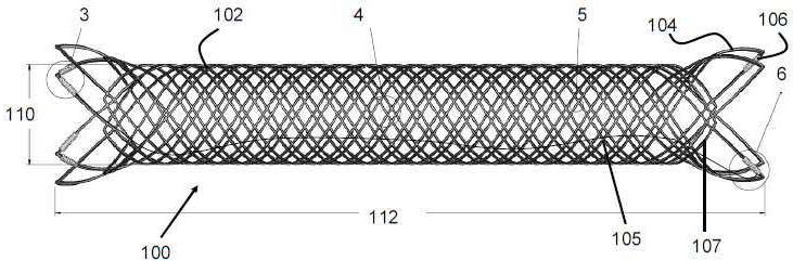
도 1은, 본 발명의 선호되는 실시예를 따르는 스텐트를 도시한 측면도.
도 2는, 도 1의 스텐트를 도시한 정면도.
도 3은, 도 1에 도시된 영역(3)을 확대도시한 도면.
도 4는, 도 1에 도시된 영역(4)을 확대도시한 도면.
도 5는, 도 1에 도시된 영역(5)을 확대도시한 도면.
도 6는, 도 1에 도시된 영역(6)을 확대도시한 도면.
도 7은, 본 발명의 선호되는 실시예를 따르는 전달 푸셔를 도시한 측면도.
도 8은, 카테터내에 위치하고 원위 단부에서 압축된 도 1의 스텐트를 가진 도 7의 푸셔(pusher) 부재를 도시한 부분단면도.
도 9는 동맥류의 개구부에 걸쳐 위치한 도 1의 스텐트를 도시한 도면.
도 10은, 도 1의 스텐트를 형성하기 위해 이용될 수 있고 본 발명을 따르는 맨드릴(mandrel)을 도시한 측면도.
도 11은, 본 발명의 선호되는 실시예를 따르는 스텐트를 도시한 측면도.
도 12 내지 도 14는, 본 발명의 선호되는 실시예를 따르는 다양한 이중 층 스텐트를 도시한 도면.
도 15는, 도 12 내지 도 14에 도시된 이중 층 스텐트를 위한 전달시스템의 횡단면도.
도 16은 튜브 또는 시트 재료로 제조된 외부 스텐트 층을 가진 이중 층 스텐트를 도시한 사시도.
도 17은, 이중 층 스텐트의 양쪽 층들이 부착되는 다양한 선택적 부착위치들을 도시한 도 15의 이중 층 스텐트의 횡단면도.
도 18은, 본 발명을 따르는 이중 층 스텐트의 또 다른 선택적 실시예를 도시한 도면.
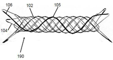
도 19는, 유동 전환층이 구성된 본 발명의 스텐트를 도시한 도면.
도 20은, 짧아진 유동 전환층을 가지고 본 발명을 따르는 이중층 스텐트를 도시한 도면.
도 21은, 늘어난 유동 전환층을 가지고 본 발명을 따르는 이중층 스텐트를 도시한 도면.
도 22는, 비대칭 배열된 유동 전환층을 가지고 본 발명을 따르는 이중층 스텐트를 도시한 도면.
도 23 및 도 24는, 본 발명의 유동 전환 층과 이용하기 위한 확대 와이어를 도시한 도면.
도 25는, 유동 전환 층의 구조속으로 일체 구성되는 확대와이어를 가진 유동 전환 층의 일부분을 도시한 도면.
도 26 내지 도 29는, 폴리머 스텐트 또는 스텐트 층을 형성하기 위한 본 발명의 과정을 도시한 도면.
도 30은, 폴리머 스텐트 또는 스텐트 층을 형성하기 위한 본 발명의 또 다른 과정을 도시한 도면.
도 31 내지 도 36은, 폴리머 스텐트 또는 스텐트 층을 형성하기 위한 본 발명의 또 다른 과정을 도시한 도면. These and other features, characteristics and advantages that the embodiments of the present invention may have are clearly understood from the following detailed description of embodiments of the invention with reference to the drawings.
1 is a side view of a stent according to a preferred embodiment of the present invention;
Fig. 2 is a front view showing the stent of Fig. 1; Fig.
Fig. 3 is an enlarged view of the
4 is an enlarged view of the
5 is an enlarged view of the
6 is an enlarged view of the
Figure 7 is a side view of a transfer pusher in accordance with a preferred embodiment of the present invention;
8 is a partial cross-sectional view of the pusher member of FIG. 7 with the stent of FIG. 1 positioned within the catheter and compressed at the distal end; FIG.
Fig. 9 is a view of the stent of Fig. 1 across an opening of an aneurysm; Fig.
Figure 10 is a side view showing a mandrel that can be used to form the stent of Figure 1 and in accordance with the present invention;
11 is a side view of a stent according to a preferred embodiment of the present invention.
12-14 illustrate various double-layer stents in accordance with a preferred embodiment of the present invention.
15 is a cross-sectional view of the delivery system for the dual-layer stent shown in Figs. 12-14. Fig.
16 is a perspective view of a dual-layer stent having an outer stent layer made of a tube or sheet material.
FIG. 17 is a cross-sectional view of the double-layer stent of FIG. 15 showing various selective attachment locations where both layers of the dual-layer stent are attached. FIG.
18 illustrates yet another alternative embodiment of a dual-layer stent in accordance with the present invention.
19 is a view showing a stent of the present invention in which a fluidization layer is formed;
Figure 20 shows a dual-layer stent according to the present invention with a shortened flow conversion layer.
Figure 21 shows a dual-layer stent according to the present invention with an extended flow conversion layer.
Figure 22 shows a dual-layer stent in accordance with the present invention with an asymmetrically arranged flow transition layer.
23 and 24 illustrate enlarged wires for use with the flow conversion layer of the present invention.
25 illustrates a portion of a flow conversion layer having an enlarged wire integrated into the structure of the flow conversion layer;
26-29 illustrate the process of the present invention for forming a polymer stent or stent layer.
30 illustrates another process of the present invention for forming a polymer stent or stent layer;
Figures 31-36 illustrate another process of the invention for forming a polymer stent or stent layer.
본 발명의 특정 실시예들은 첨부된 도면들을 참고하여 설명된다. 그러나 본 발명은 서로 다른 다수의 형태로 실시될 수 있고 본 명세서에 공개된 실시예들로 국한되지 않는다. 상기 공개가 완전하도록 실시예들이 제공되며, 본 발명의 범위가 당업자들에게 완전히 전달된다. 첨부된 도면들에 도시된 실시예들에 관한 상세한 설명에 이용된 용어는, 본 발명을 제한하기 위한 것이 아니다. 도면들에서 동일한 도면부호들은 동일한 구성요소들을 나타낸다.
Specific embodiments of the present invention are described with reference to the accompanying drawings. The invention may, however, be embodied in many different forms and should not be construed as limited to the embodiments set forth herein. Embodiments are provided in which the disclosure is complete and the scope of the invention is fully conveyed to those skilled in the art. The terminology used in the detailed description of the embodiments shown in the accompanying drawings is not intended to limit the present invention. In the drawings, the same reference numerals denote the same elements.
다르게 정의되지 않는다면, 본 명세서에서 이용되는 (기술용어 및 과학용어들을 포함한) 모든 용어들은, 당업자들에 의해 공통적으로 이해되는 동일한 의미를 가진다. 또한 일반적으로 이용되는 사전에 정의된 용어들과 같은 용어들은, 관련 기술의 의미와 동일한 의미를 가진 것으로 해석되어야 하고 본 명세서에서 정의되지 않는다면 이상적인 의미 또는 너무 형식적인 의미로 해석되지 않는다.
Unless otherwise defined, all terms (including technical and scientific terms) used herein have the same meaning as commonly understood by one of ordinary skill in the art. Also, terms such as commonly used predefined terms should be construed as having the same meaning as the meaning of the related art, and are not to be construed as ideal or too formal unless defined otherwise herein.
도 1은, 본 발명의 선호되는 실시예를 따르는 스텐트(100)를 도시한다. 상기 스텐트(100)는, 스텐트(100)의 양쪽 단부에 형성된 주변부(perimeter) 주위에서 복수 개의 루프(loop)(104)들을 가지며 일반적으로 원통형상을 형성하도록 단일의 와이어(102)로부터 직조되거나 서로 꼬이게(braided) 된다.
Figure 1 shows a
도 1 및 도 5의 영역(5)에 도시된 것처럼, 상기 단일 와이어(102)의 단부들은 용접( 용접된 영역(116)을 참고), 결합제 또는 유사한 접착 기구에 의해 서로 연결될 수 있다. 단부들이 용접되거나 결합되면, 와이어(102)는 "자유"단부들을 가지지 않는다.
The ends of the
각각의 루프(104)들은 한 개이상의 코일 부재(106)를 포함할 수 있다. 상기 코일 부재(106)는 상기 루프(104)의 와이어(102)주위에 배열되는 것이 선호되고, 하기 상세한 설명과 같이, 스텐트(100)의 근위 단부와 원위 단부를 나타낸다. 추가로, 상기 코일 부재(106)들은 하기 상세한 설명과 같이 전달장치내에서 추가의 고정(anchoring)하중을 제공할 수 있다.
Each
일 실시예에서, 상기 스텐트(100)의 원위단부는 두 개의 코일 부재(106)를 각각 가진 적어도 두 개의 루프(104)들을 포함하고, 상기 스텐트(100)의 근위단부는 한 개의 코일 부재(106)를 각각 가진 적어도 두 개의 루프(104)를 포함한다. 그러나, 상기 스텐트(100)는 모든 갯수의 루프(104)상에 모든 갯수의 코일 부재(106)를 포함할 수 있다.
In one embodiment, the distal end of the
상기 코일 부재(106)들은 상기 루프(104)의 중심영역 근처에 위치하여, 스텐트(100)가 접혀진 상태에 있을 때 상기 코일 부재(106)는 상기 스텐트(100)의 바로 원위 단부 또는 근위단부와 근접하게 위치한다.
The
각각의 코일 부재(106)는 상기 루프(104)의 일부분을 감싸는 와이어(105)로 구성되는 것이 선호된다. 각각의 코일 부재(106)는(도 3에 도시된 것처럼) 분리된 와이어(105)로 구성될 수 있거나 단일의 와이어(105)가 (도 1, 도 3 및 도 6에 도시된 것처럼) 복수 개의 코일 부재(106)들을 형성할 수 있다. 선호되는 실시예에서, 일부 코일 부재(106)는 와이어(105)의 분리된 섹션들로 구성되는 반면에, 다른 코일 부재(106)는 양쪽 단부에서 연속적이고 동일한 와이어(105)로부터 제조된다. 도 1에 도시된 것처럼, 상기 와이어(105)는 상기 스텐트(100)의 내측부분 또는 루멘내에 위치하여 상기 스텐트(100)의 각 단부에서 코일 부재(106)와 연결될 수 있다. 선택적으로, 상기 와이어(105)는 상기 스텐트(100)의 와이어(102)속으로 직조될 수 있다. It is preferred that each
상기 코일 부재(106)의 와이어(105)는 탄탈륨 또는 백금과 같은 방사선 불투과성 재료로 구성되는 것이 선호된다. 상기 와이어(105)는 약 0.00225"의 직경을 가지는 것이 선호된다.
The
선택적으로, 상기 코일 부재(106)는, 상기 루프(104)에 배열되거나 부착되는 방사선 불투과성의 슬리브(sleeve)일 수 있다.
Optionally, the
일 실시예에서, 상기 스텐트(100)의 근위 단부(proximal end)에 위치한 루프(104)는 (도 3에 도시된 것처럼) 루프(104)의 각 측부에서 한 개의 코일(106)을 가지고, 스텐트(100)의 원위단부(distal end)는 (도 6에 도시된 것처럼) 각 루프(104)의 한쪽 측부에서 단지 한 개의 코일(106)을 포함한다.
In one embodiment, the
상기 스텐트(100)의 직조 패턴(pattern)에 의해 원위 코일(106)은 수축작용시 스텐트(100)의 외경으로부터 노출되거나 "튀어나오는(sticking up)"것이 방지된다. 그러므로, 위치를 재설정하고 재배치(redeploy)하기 위해 상기 스텐트(100)가 카테터속으로 들어가도록 사용자가 결정하면, 상기 원위 코일(106)은 카테터의 원위 변부를 접촉하거나 포착하지 못하여 스텐트가 들어가는 동안 발생할 수 있는 스텐트(100)의 손상을 최소화하게 된다.
The woven pattern of the
들어가는 과정동안 상기 원위 코일(106)의 노출을 최소화하기 위한 특정 기술은, 상기 와이어(102)의 일부분들이 코일(106)을 가진 루프(104)의 측부를 제외하고 중첩(즉, 상대적으로 큰 외경 위치에 배열)되도록 스텐트(100)를 직조하는 것이다. 도 6에 도시된 것처럼, 상대적으로 작은 일부 루프(107)들은 코일(106)을 포함하는 루프(104)의 제 1 측부(104A)( 위치(109)를 참고)와 중첩되도록 직조되고, 다른 작은 루프(104)들은 루프(104)의 제 2 측부(104B)아래에서(위치(111)를 참고) 직조된다.
Particular techniques for minimizing the exposure of the
사용자가 상기 스텐트(100)를 카테터속으로 들어가게 함에 따라, 상기 스텐트(100)가 직경방향으로 압축되며 상기 작은 루프(107)는 내부(스텐트의 통로 중심을 향해)로 이동하여, 루프(104)의 제 1 측부(104A)에서 내부를 향해 압축된다. 이와 관련하여, 상기 작은 루프(107)는 내부를 향한 하중 또는 압축 하중을 상기 루프(104)의 제 1 측부(104A)에 대해 가한다. 상기 구조에 의하면, 루프(104)의 제 1 측부(104A) 따라서 코일(106)은 스텐트가 들어가는 동안 스텐트(100)의 가장 외측의 직경에 위치하지 못하여 상기 코일(106)이 전개 카테터의 원위단부에 포착되거나 걸리게(hooked) 될 가능성을 감소시키는 것이 보장된다.
As the user moves the
도 1 및 도 2에 가장 양호하게 도시된 것처럼, 루프(104)는 상기 스텐트(100)의 주 몸체가 가지는 직경에 대해 최대로 확대될 때 외경(114)에 대해 편향되거나 확대된다. 상기 루프(104)들은 또한 상기 주 몸체와 동일하거나 상대적으로 작은 직경까지 확대될 수도 있다.
As best shown in Figures 1 and 2, the
상기 스텐트(100)는, 도 9에 도시된 것처럼, 인체내부의 관(152)을 위한 크기를 가진 직경(110)을 가지는 것이 선호된다. 상기 직경(110)은 약 2mm 내지 10mm 인 것이 더욱 선호된다. 상기 스텐트(100)의 길이는 도 9에 도시된 것처럼 동맥류(150)의 개구를 지나 연장되는 크기를 가지는 것이 선호된다. 상기 스텐트(100)의 길이는 약 5mm 내지 100mm 인 것이 더욱 선호된다.
It is preferred that the
도 7 및 도 8은, 본 발명을 따르고 상기 스텐트(100)를 전달하기 위해 이용될 수 있는 전달시스템(135)을 도시한다. 카테터 또는 덮개(133)가 전달 푸셔(delivery pusher)(130)상에 위치하고 스텐트(100)를 스텐트의 압축된 위치로 유지시킨다. 상기 덮개(133)의 원위 단부가 원하는 목표위치(즉 동맥류(150)와 근접한 위치)에 도달하면, 상기 덮개(133)는 상기 스텐트(100)를 구속해제하기 위해 쑥 들어가게 된다.
Figures 7 and 8 illustrate a
상기 전달 푸셔(130)는 코어 부재(core member)(132)로 구성되고, 상기 코어부재의 직경은 (니티놀(nitinol)로 제조된) 코어부재의 원위 단부와 근접한 위치에서 감소(tapered)된다. 코아 부재(132)의 감소된 단부가 가지는 원위 영역은 상대적으로 큰 직경을 가진 제 1 와이어 코일(134)를 포함하고, 상기 제 1 와이어 코일은 스테인레스 강으로 제조되며 상기 코어부재(132)상의 제 위치에 용접되거나 납땜된다. 상기 코어부재(132)에 고정되고 백금과 같은 방사선 불투과성 재료로 제조되는 것이 선호되는 제 1 표시 밴드(136)가 상기 코일구조의 와이어에 대해 떨어져 배열된다.
The
상대적으로 작은 직경을 가진 제 2 와이어 코일(138)은 상기 표시밴드(136)와 떨어져 배열되고 스테인레스 강 또는 플라스틱 재질의 슬리브로 제조되는 것이 선호된다. 제 2 표시 밴드(140)는 제 2 와이어 코일(138)과 떨어져 배열되고 백금과 같은 방사선 불투과성 재료로 제조되는 것이 선호된다. 상기 코어부재(132)에서 노출된 좁은 섹션(142)이 상기 제 2 표시밴드(140)로부터 떨어져 배열된다. 마지막으로, 코일구조를 가진 원위 팁(distal tip) 부재(144)가 상기 코어부재(132)의 원위단부에 배열되고 백금 또는 탄탈륨과 같은 방사선 불투과성 재료로 제조되는 것이 선호된다.
The
일 실시예에서, 상기 덮개(133)는 약 0.027"의 내경을 가지고 1 미터의 길이를 가진다. 상기 전달 푸셔(130)는 또한 약 2미터의 길이를 가진다. 상기 전달 푸셔(130)의 섹션은 다음과 같은 직경을 가지는 것이 선호된다. 상기 코어부재(132)의 근위 영역은 약 0.0180인치이고, 상기 제 1 와이어 코일(134)은 약 0.0180인치이며, 제 1 표시밴드(136)는 약 0.0175인치이고, 제 2 와이어 코일(138)은 약 0.0050인치이며, 제 2 표시밴드(140)는 약 0.0140인치이고, 원위 코어 부재 섹션(142)은 약 0.003인치이며, 원위 팁 부재(144)는 약 0.0100인치이다. 상기 전달 푸셔(130)의 섹션들은 다음과 같은 길이를 가지는 것이 선호된다. 코어부재(132)의 근위 영역은 약 1미터이고, 제 1 와이어 코일(134)은 약 45cm 이며, 제 1 표시밴드(136)는 약 0.020인치이고, 제 2 와이어 코일(138)은 약 0.065인치이며, 제 2 표시밴드(140)는 약 0.020인치이고, 원위 코어 부재 섹션(142)은 약 10cm 이며, 원위 팁 부재(144)는 약 1cm 이다.
In one embodiment, the
도 8에 도시된 것처럼, 상기 스텐트(100)는 상기 전달 푸셔(130)의 원위단부상에 가압되어, 스텐트(100)의 근위단부에 있는 코일 부재(106)는 상기 제 1 표시밴드(136)와 제 2 표시밴드(140)사이에 위치한다. 상기 근위 코일부재(106)는 표시밴드(136 또는 140)와 접촉하지 않고 마찰력에 의해 상기 덮개(133)와 제 2 코일 영역(138)사이에 유지되는 것이 선호된다.
The
전달 푸셔의 원위단부가 원하는 목표위치(예를 들어, 동맥류와 근접한 위치)와 근접한 영역에 도달할 때, 상기 덮개(133)는 전달 푸셔(130)에 대해 근위위치로 들어간다. 도 9에 도시된 것처럼, 상기 덮개(133)가 상기 스텐트(100)를 노출시킬 때 상기 스텐트(100)는 관(152)의 벽에 대해 확대된다.
The
원위방향으로 상기 전달 푸셔(130)를 들어가게 하여 상기 스텐트(100)는 쑥 들어갈 수 있고 따라서, 표시밴드(140)는 근위 표시밴드(106)와 접촉하고 상기 스텐트(100)를 상기 덮개(133)속으로 끌어 당긴다.
The
일 실시예에서, 폐색 코일과 같은 폐색장치 또는 재료가 동맥류(150)내에 전달된 후에 상기 스텐트(100)는 동맥류(150)의 개구부위로 전달될 수 있다. 이와 관련하여, 상기 스텐트(100)는, 치료장치들이 상기 동맥류(150)로부터 밀려나오고 합병증을 유발하거나 치료효과가 감소되는 것을 방지한다.
In one embodiment, the
일 실시예에서, 상기 와이어(102)는 약 0.001 인치 내지 0.010인치의 직경을 가지고 니티놀과 같은 형상기억(shape- memory) 탄성재료로 제조된다.
In one embodiment, the
상기 와이어(102)의 직경은 또한 상기 스텐트(100)의 길이에 걸쳐서 변화할 수 있다. 예를 들어, 근위 단부와 원위단부에 근접한 상기 와이어(102)의 직경은 상기 스텐트(100)의 중간부분이 가지는 직경보다 더 클 수 있다. 또 다른 실시예에서, 상기 원위 단부와 근위단부는 중간부분보다 더 작을 수 있다. 또 다른 실시예에서, 상기 와이어(102)의 직경은 상기 스텐트(100)의 길이를 따라 상대적으로 큰 직경과 상대적으로 작은 직경을 교대로 가질 수 있다. 또 다른 실시예에서, 상기 와이어(102)의 직경은 스텐트(100)의 길이를 따라 점차적으로 증가하거나 감소할 수 있다. 또 다른 실시예에서, 상기 루프(104)들은, 스텐트(100)의 주 몸체를 포함한 와이어(102)의 직경보다 크거나 작은 직경을 가진 와이어(102)로 구성될 수 있다. 좀더 상세한 실시예에서, 상기 루프(104)의 와이어(102)가 가지는 직경은 약 0.003인치이며, 상기 스텐트(100)의 몸체가 가지는 와이어(102)는 약 0.002인치일 수 있다.
The diameter of the
또 다른 실시예에서, 와이어(102)는 상기 스텐트(100)의 압축 및/또는 확대된 구조에서 또 다른 섹션과 교차하는 와이어(102)의 선택영역들이 감소된 두께를 가질 수 있다. 이와 관련하여, 상기 스텐트(100)의 두께는 일부 구조에서 효과적으로 감소될 수 있다. 예를 들어, 상기 와이어(102)가 압축된 구조일 때 겹쳐(overlapped)지는 영역에서 와이어(102)의 섹션들이 감소되면, 상기 스텐트(100)의 전체 프로파일 또는 두께가 감소되어 스텐트(100)는 상대적으로 더 작은 전달 카테터속에 잠정적으로 조립될 수 있다.
In yet another embodiment, the
상기 와이어(102)의 직경 변화는, 직경을 감소시키기 위해 조립된 스텐트(100)의 일부분들을 전해연마(electropolishing), 에칭(etching) 또는 감소시켜서 이루어질 수 있다. 선택적으로, 상기 와이어(102)의 영역들은, 스텐트(100)의 형상속으로 직조되거나 감기기 전에 감소될 수 있다. 이와 관련하여, 원하는 직조 패턴(pattern)이 결정되고, 원하는 추후 직조(post-weaving), 감소된 직경의 영역들이 계산되고 감소되며, 마지막으로 스텐트(100)는 수정된 와이어(102)로 직조될 수 있다.
The change in diameter of the
또 다른 변형예에서, 미리 직조된 와이어(102)는 단일 방향으로 테이퍼(taper)구조를 가지고 스텐트(100)를 형성하기 위해 서로 직조될 수 있다.
In yet another variation, the
예시적인 준비작업에서, 0.0035인치의 직경을 가진 니티놀 와이어가 맨드릴(160) 주위에 감기거나 직조된다. 도 10에 도시된 것처럼, 맨드릴(160)은 각각의 단부를 통해 연장되는 세 개의 핀(pin)(162,164,166)들을 가질 수 있어서, 각 핀이 가지는 각 단부의 일부분은 맨드릴(160)의 몸체로부터 연장된다. 상기 와이어(102)는 한 개의 핀에서 시작되고 다음에 맨드릴(160)의 몸체주위에서 시계방향으로 3.0625 회전만큼 감긴다. 상기 와이어(102)는 근접한 핀주위에서 구부러지고 다음에 맨드릴(160)의 다른 측부를 향해 시계방향으로 3.0625회전만큼 감기며 와이어(102)의 앞서 감긴 섹션 아래 및 위를 통과한다. 상기 과정은, 8개의 루프들이 각각의 단부에 형성될 때까지 반복된다.
In an exemplary preparation operation, a nitinol wire having a diameter of 0.0035 inches is wound or woven around the
또 다른 예에서, 맨드릴(160)은 8 개의 핀들을 가지고 와이어(102)는 2.375 회전만큼 감긴다. 또 다른 예에서, 상기 맨드릴(160)은 16개의 핀을 가지고 와이어(102)는 3.0625회전만큼 감긴다. 또 다른 예에서, 상기 맨드릴은 8 개내지 16개의 핀을 가지고 와이어(102)는 2.375 회전 내지 3.0625회전만큼 감긴다.
In another example,
일단 감기면, 상기 스텐트(100)는 예를 들어, 약 500℃에서 약 10분동안 맨드릴(160)위에서 열성형(heat-set)된다. 상기 니티놀 와이어에 형성된 두 개의 자유단부들은 서로 레이저로 용접되고 전해연마되어 최종 와이어 직경은 약 0.0023인치이다.
Once wound, the
마지막으로, 약 0.00225인치의 직경을 가진 방사선 불투과성 와이어(105)는 루프(104)의 서로 다른 영역들위에 감기고, 코일 부재(106)를 형성한다. 상기 와이어(105)는 각각의 코일 부재(106)를 형성하기 위해 약 0.04인치의 길이에 대해 감긴다.
Finally, the
또 다른 실시예에서, 상기 스텐트(100)는 단일 와이어(102)대신에 복수 개의 분리된 와이어들로 제조될 수 있다. 상기 복수 개의 와이어들이 가지는 단부들은 성형 루프(104)를 위해 자유상태로 남겨지거나 용접되거나 서로 부착 또는 융합될 수 있다. 또 다른 실시예에서, 스텐트(100)는 레이저 절단, 에칭, 기계가공 또는 다른 공지된 제조방법에 의해 형성될 수 있다.
In another embodiment, the
상기 와이어(102)는 니티놀과 같은 형상 기억 금속으로 구성되는 것이 선호된다. 선택적으로, 상기 형상 기억금속은 혈액에 노출될 때 부풀어오르거나 확대되는 서로 다른 다양한 치료용 코팅 또는 하이드로겔 코팅을 포함할 수 있다. 상기 와이어(102)는 또한 생체적합성을 가진 폴리머 재료 (예를 들어, PET) 또는 하이드로겔 재료로 제조될 수 있다.
The
도 11은, 스텐트(100)의 각 단부가 상기 스텐트(100)의 네 개의 루프(104)대신에 세 개의 루프(104)들을 포함한다는 것을 제외하면, 상기 스텐트(100)와 유사한 스텐트(190)의 실시예를 도시한다. 또한, 각각의 코일(106)을 형성하는 상기 방사선불투과성 와이어(105)는 또한 스텐트(190)내부로 직조되고 상기 코일(104)의 적어도 일부가 스텐트(190)의 각 단부에 연결되는 것이 선호된다. 마지막으로, 와이어(102)는 스텐트(190)의 길이를 따라 약 12회 앞뒤로 직조된다.
11 shows a
도 12는 본 발명을 따르는 이중 층 스텐트(200)의 선호되는 실시예를 도시한다. 일반적으로, 상기 이중 층 스텐트(200)는, 도 1 내지 도 9에 도시된 상기 스텐트(100)와 유사한 외부 고정(outer anchoring) 스텐트(100)를 포함한다. 상기 이중 층 스텐트(200)는 또한, 고정 스텐트(100)의 내부 루멘 또는 통로내에 배열되는 내부의 유동전환 층(202)을 포함한다.
12 shows a preferred embodiment of a
종종, 상대적으로 작은 와이어를 가진 스텐트는 적절한 팽창 하중을 제공하지 못하고 따라서, 목표위치에서 스텐트의 위치를 신뢰성있게 유지하지 못한다. 또한, 다수의 와이어로 형성되고 직조된 종래기술의 스텐트는, 환자의 혈관을 찌르거나 손상시킬 수 있는 자유단부들을 가질 수 있다. 이에 반해서, 상대적으로 큰 와이어는 원하는 위치에서 혈액유동을 수정하기 위해 충분히 타이트(tightly)하게 직조되기 어렵다(즉, 인접한 와이어들사이에 큰 공간이 존재). 상기 스텐트(200)는, 원하는 고정 하중을 제공하기 위해 상대적으로 큰 와이어 꼬임 고정(wire braid anchoring) 스텐트(100) 및 혈액을 전환하기 위해 상대적으로 작은 와이어 꼬임 유동전환층(202)을 포함하여 상기 문제점을 극복하려한다.
Often, stents with relatively small wires do not provide adequate expansion loads and thus do not reliably maintain the position of the stent at the target location. Also, prior art stents formed and woven from multiple wires may have free ends that can pierce or damage the patient ' s blood vessels. On the other hand, relatively large wires are difficult to tightly weave (i.e., there is a large space between adjacent wires) to modify the blood flow at the desired location. The
일 실시예에서, 유동 전환 층(202)은 약 0.0005인치 내지 0.002인치의 직경을 가지고 니티놀과 같은 기억 탄성재료로 제조된 적어도 32개의 와이어(204)들로 구성된다. 상기 와이어(204)들은 0.010인치보다 작은 기공(pore) 크기를 가진 관 형상으로 직조되거나 서로 꼬인다. 상기 꼬임(braiding)은, 종래기술로 공지되고 다이아몬드 형상의 패턴과 같은 규칙적인 패턴으로 와이어(204)를 꼬게 되는 꼬임기계에 의해 이루어진다.
In one embodiment, the
상기 유동 전환 층(202)은, 스텐트(100)의 와이어(102)와 관련한 상기 패턴들 및 기술과 유사하고 감소된 직경을 가진 와이어(204)의 영역을 가질 수 있다. 또한, 유동 전환 층(202)은 얇은 관을 레이저 절단하거나 에칭하여 형성될 수 있다.
The
본 실시예에서, 상기 유동 전환 층(202)의 원위 단부와 근위 단부는 유동 전환 층(202)의 길이에 대해 수직이다. 그러나 상기 단부들은, 일치하거나 마주보거나 불규칙적인 각 구조로 유동 전환 층(202)의 길이에 대해 각을 형성할 수도 있다.
In this embodiment, the distal end and proximal end of the
도 13 및 도 14에서 가장 양호하게 도시된 것처럼, 상기 이중 층 스텐트(200)의 근위 단부는, 상기 고정 스텐트(100)를 유동 전환 층(202)과 연결시키는 복수 개의 부착부재(206)를 포함한다. 상기 부착부재(206)는 탄탈륨 와이어(이 경우 0.001"의 직경을 가짐)로 제조되고 와이어(102) 및 와이어(202)의 일부분에 부착될 수 있다. 또 다른 실시예에서, 상기 유동 전환 층(202)의 근위 단부는 상기 고정 스텐트(100)의 와이어(102)에 크림핑(crimped)가공된다. 또 다른 실시예에서, 상기 스텐트(100)와 유동 전환 층의 일부분들은 부착을 위해 서로를 통과하여 직조될 수 있다. 또 다른 실시예에서 상기 스텐트(100)는 아이 루프(eye- loop) (예를 들어, 레이저 절단 또는 에칭에 의해 형성됨) 또는 와이어(202)들이 부착을 위해 통과하여 직조될 수 있는 크기를 가진 유사한 특징을 가지며 구성될 수 있다.
As best shown in Figures 13 and 14, the proximal end of the double-
고정 스텐트(100)와 유동 전환 층(202)은 서로 다른 직조 패턴 또는 직조 밀도를 가질 수 있기 때문에, 고정 스텐트(100)와 유동 전환 층의 길이는 직경이 확대되는 비율과 다른 비율로 감소된다. 이 경우, 상기 부착부재(206)는 전달장치내부에 형성된 방향과 같이 유동 전환 층(202)과 고정 스텐트(100)의 근위단부에 위치하거나 상기 근위단부와 근접하게(즉, 원위 팁 부재(144)와 마주보는 단부에) 위치한다. 그러므로, 상기 스텐트(200)가 전개됨에 따라, 고정 스텐트(100) 및 유동 전환 층(202)의 길이는 감소 (또는 스텐트(200)가 전달장치내부로 들어가는 경우 증가)될 수 있고 서로 부착된 상태를 유지한다. 선택적으로, 부착 부재(206)는 이중 층 스텐트(200)의 길이를 따라 한 개이상의 위치들(원위단부, 양쪽 단부들, 중간 또는 양쪽 단부들 및 중간영역)에 배열될 수 있다.
Because the fixed
상기 스텐트(200)의 실시예에서, 유동 전환 층(202)은 약 145ppi의 밀도를 가진 48 개의 와이어를 포함하고 약 3.9mm의 직경까지 완전히 확대된다. 외부의 스텐트(100)는 2.5 회전의 감기 패턴으로 감기는 단일 와이어를 포함하고 약 4.5mm의 직경까지 완전히 확대된다. 층(100,202)들이 완전히 확대될 때, 길이들은 약 17mm 및 13mm이다. 층(100,202)들이 전달장치의 0.027인치 영역까지 압축될 때, 층들의 길이는 각각 약 44mm 및 37mm이다. 층(100,202)들이 전달장치의 3.75mm 관내에서 확대될 때, 층들의 길이는 각각 약 33 mm 및 21mm이다.
In the embodiment of the
상기 이중 층 스텐트(200)의 선호되는 실시예에서, 상기 유동 전환 층(202)은 약 0.0005 인치 내지 약 0.0018인치의 직경을 가진 와이어(204)로 구성되고, 스텐트(100)의 와이어(102)는 약 0.0018인치 내지 약 0.0050 인치의 직경을 가진다. 그러므로, 상기 와이어(102)와 와이어(204)가 가지는 직경의 선호되는 최소비율은 약 0.0018 인치 대 0.0018인치 (또는 약 1:1 비율)이고, 선호되는 최대 비율은 약 0.0050/0.0005인치( 또는 약 10:1)이다.
In the preferred embodiment of the double-
이중 층 스텐트(200)는, 스텐트(100) 또는 유동 전환 층(202) 만 이용될 때보다 상대적으로 큰 (스텐트의 약 50% 반경방향 압축시 작용하는 반경방향 하중으로 정의되는) 반경방향 하중을 발생시킬 수 있다. 상대적으로 큰 상기 반경방향 하중에 의해 상기 이중 층 스텐트(200)는 전개 및 고정 특성이 개선될 수 있다. 이중 층 스텐트 실시예의 예시적인 시험에서, 외부의 스텐트(100)만 이용되면 평균 반경방향 하중은 약 0.13 N 이고, 유동 전환 층(202)만 이용되면 평균 반경방향 하중은 약 0.05N이며, 이중 층 스텐트(200)는 약 0.26N의 평균 반경방향 하중을 가진다. 다시 말해, 상기 이중 층 스텐트(200)의 평균 반경방향 하중은, 상기 유동 전환 층(202)과 스텐트(100)의 조합이 가지는 평균 반경방향 하중과 동일하거나 더 크다.
The dual-
유동 전환 층(202)내부의 기공(porosity)비율(즉, 개방된 공간 대 개방되지 않은 공간의 백분율)은 유동 전환 층이 반경방향으로 확대됨에 따라 변화한다는 것을 주목해야 한다. 이와 관련하여, 원하는 기공비율 또는 기공크기는, 서로 다른 크기를 가진 스텐트(200)들( 즉 서로 다른 직경까지 완전히 확대된 스텐트들)을 선택하여 제어될 수 있다. 하기 표 1은 서로 다른 예시적인 기공비율을 설명하고, 특정 목표 관(vessel)내에서 스텐트(200)의 크기를 변화( 즉, 완전히 확대된 스텐트의 직경)시켜서 유동 전환 층(202)이 구해질 수 있다. 이용되는 와이어의 개수, 인치당 픽(pick)(PPI) 또는 와이어 크기와 같은 유동 전환 층(202)의 다른 특징들을 수정하여 기공비율이 수정될 수 있다. 유동 전환 층(202)은 확대될 때 약 45 내지 70%의 기공비율을 가지는 것이 선호된다.
It should be noted that the porosity ratio within the fluidization layer 202 (i.e., the ratio of the open space to the unopened space) changes as the fluidization layer expands radially. In this regard, the desired porosity or pore size can be controlled by selecting
스텐트(100)의 기공비율에 대하여 유사한 기술이 이용될 수 있다. 상기 스텐트(100)는 확대될 때, 약 75% 내지 95% 및 약 80% 내지 88%의 범위인 것이 선호되는 기공비율을 가진다. 다른 식으로 설명하면, 상기 스텐트(100)는 약 5% 내지 25% 및 12% 내지 20%가 선호되는 금속의 백분율 또는 금속 표면적을 가지는 것이 선호된다. A similar technique can be used for the porosity ratio of the
확대 크기(mm)Target vessel
Magnification (mm)
(202)의 다공율The flow-
Lt; RTI ID = 0.0 > 202 &
스텐트(100)는, 완전히 확대된 위치에 있거나 (목표 직경을 가진)목표 관내에 위치할 때, 유동 전환 층(202)의 외경에 대해 상대적으로 큰 내경을 가지거나 "과대 크기(oversized)"를 가질 수 있다. 상기 스텐트(100)의 내부표면과 상기 유동 전환 층(202)의 외부표면사이의 차이는, 약 0.1mm 내지 약 0.6mm( 두 개의 표면들사이에서 약 0.05mm 내지 약 0.3mm의 간격)인 것이 선호된다. 일반적으로, 이중 층 스텐트(200)는 환자의 목표 관에 대해 경미한 과대 크기를 가질 수 있다. 이와 관련하여, 외부의 스텐트(100)는 목표관의 조직속으로 경미하게 가압될 수 있고, "과소크기(undersized)를 가진" 유동 전환 층(202)이 관의 조직과 상대적으로 근접하거나 심지어 접촉하는 프로파일을 유지할 수 있게 한다. 상기 크기에 의해 상기 스텐트(100)는 상기 관내부에 더욱 양호하게 고정되고 상기 유동 전환 층(202)과 관 조직(vessel tissue)사이에 밀착되어 접촉할 수 있다. 표 1의 예시적인 데이터에 도시된 것처럼, 상기 이중 층 스텐트(200)의 "과대 크기"에 의해, 유동 전환 층(202)의 완전히 확대된 (그리고 방해받지 않는 상태의) 위치에 대해 유동 전환 층(202)의 기공비율은 약 10 내지 15%만큼 증가될 수 있다.
The
이중 층 스텐트(200)는, 특히 유동 전환 층(202)과 유사한 크기와 두께를 가진 스텐트와 비교할 때, 개선된 추적(tracking) 및 전개 성능을 제공할 수 있다. 예를 들어, 시험에 의하면, 단독의 유동 전환 층과 유사한 스텐트와 비교할 때 전달장치로부터 이중 층 스텐트(200)가 전개되거나 들어가는 동안 요구되는 하중이 감소된다. 이중 층 스텐트(200)의 일부분으로서 외부의 스텐트(100)가 포함되면, 상기 이중 층 스텐트(200)의 기공비율과 반경방향 하중에 대한 전달장치내부의 마찰이 감소된다.
The dual-
이중 층 스텐트(200)는 약 0.2lbs 내지 약 0.6lbs의 하중에 의해 전개되거나 집어 넣어질 수 있다. 유동 전환 층(202)의 외부에 스텐트(100)를 포함하면, 유동 전환 층(202)만( 즉, 도 19에 도시된 것처럼 자신에 의해 이용되는 단독 층(standalone layer)(202))을 전개/집어넣는 과정과 비교하여 전개하중이 약 10내지 50%만큼 감소될 수 있다. 단지 유동 전환 층(202)과 비교하여 이중 층 스텐트(200)를 위한 전개하중이 상대적으로 적게 요구되기 때문에, 전개장치로부터 상대적으로 더욱 바람직한 전달특성이 구해질 수 있다.
The
전개하고 집어넣기 위한 하중에 관한 예시적인 시험이, 도 12 내지 도 14에 도시된 것처럼 예시적인 이중 층 스텐트(200)에 대해 수행되고 도 19에 도시된 것처럼 유동 전환 층(202)에 대해서만 수행되었다. 이중 층 스텐트(200)는 약 0.3lbs의 평균최대 전개하중을 요구하고 약 0.4lbs의 평균 최대 집어넣기 하중을 요구한다. 단지 유동 전환 층(202)의 스텐트는 약 0.7lbs의 평균전개하중을 가진다. 구속 또는 구속해제 기구가 없기 (예를 들어, 도 15에 도시된 것처럼, 표시밴드(140)와 접촉하는 코일(106)들이 없기)때문에, 상기 시험에서 유동 전환 층(202)의 스텐트는 집어 넣어질 수 없다. 이중 층 스텐트(200)는 도 1 내지 도 10에 도시된 실시예에 관해 설명된 차이와 유사하게, 상기 외부 스텐트(100)의 와이어(102)가 가지는 직경의 차이를 포함한다. 구체적으로, 스텐트(100)의 중간영역을 구성하는 와이어(102)가 감소된 직경을 가지고, 단부들(예를 들어, 루프(104)들)에서 와이어(102)는 중간영역보다 큰 직경을 가진다. 예를 들어, 상기 중간영역은 와이어(102)의 직경을 감소시키기 위해 전해연마될 수 있고, 스텐트(100)의 상기 단부들은 전해연마로부터 보호되고 원래의 직경을 유지할 수 있다. 다른 식으로 설명하면, 스텐트(100)의 두께는 중심영역에서 상대적으로 얇다. 중간영역에서 감소된 두께는 또한, 와이어를 이용하지 않는 외부 스텐트(예를 들어, 도 16에 도시된 레이저 절단 튜브 스텐트)의 실시예들에도 적용될 수 있다. 상기 직경차이를 가진 이중 층 스텐트(200)의 실시예에 관한 시험에서, 상대적으로 작은 전개 및 집어넣기 하중이 관찰되었다. 상기 상대적으로 작은 전개 및 집어넣기 하중은 바람직한 추적, 전개 및 집어넣기 특징을 제공할 수 있다. 상기 중간영역의 와이어(102)는 스텐트(100)의 원위 및 근위 영역들보다 약 0.0003인치 내지 약 0.001인치 작은 직경 또는 두께를 가지는 것이 선호된다. 상기 중간영역의 와이어(102)는 스텐트(100)의 원위 및 근위 영역들보다 약 10% 내지 약 40% 선호적으로 약 25%만큼 작은 직경 또는 두께를 가지는 것이 선호된다.
An exemplary test of the load for deployment and insertion was performed for the exemplary
예를 들어, 일 실시예는, 약 0.0025인치의 직경을 가진 와이어(102)로 구성된 단부들 및 약 0.0021인치의 직경을 가진 와이어(102)로 구성된 중간영역을 포함한다. 상기 실시예는, 약 0.2lbs 내지 0.4lbs 내에서 약 0.3lbs의 최대 평균 전개하중 및 약 0.3lbs 내지 0.4lbs 내에서 약 0.4lbs의 최대 평균 집어넣기 하중에 대한 평균을 구한다.
For example, one embodiment includes an end region comprised of a
또 다른 실시예는 약 0.0020인치의 직경을 가진 와이어(102)로 구성된 단부들 및 약 0.0028인치의 직경을 가진 와이어(102)로 구성된 중간영역을 포함한다. 상기 실시예는, 약 0.2lbs 내지 0.3lbs 내에서 약 0.2lbs의 최대 평균 전개하중 및 약 0.3lbs 내지 0.4lbs 내에서 약 0.3lbs의 최대 평균 집어넣기 하중에 대한 평균을 구한다.
Another embodiment includes an end region comprised of a
또 다른 실시예는 약 0.0021인치의 직경을 가진 와이어(102)로 구성된 단부들 및 약 0.0028인치의 직경을 가진 와이어(102)로 구성된 중간영역을 포함한다. 상기 실시예는, 약 0.3lbs 내지 0.4lbs 내에서 약 0.4lbs의 최대 평균 전개하중 및 약 0.5lbs 내지 0.6lbs 내에서 약 0.6lbs의 최대 평균 집어넣기 하중에 대한 평균을 구한다.
Another embodiment includes an end region comprised of a
도 15에 관하여, 본 발명에 따라 전달장치(210)는 환자내에 스텐트(200)를 전개하기 위한 것이다. 상기 전달장치(210)는 일반적으로 상기 전달장치(135)와 유사하고 표시밴드(140)위에 상기 스텐트(200)를 압축된 위치에 유지하기 위해 전달 푸셔(130)상에 배열된 덮개(133)를 포함한다.
Referring to Fig. 15, a
상기 장치와 같이, 스텐트(200)의 근위단부(201)는 원위 표시 밴드(140)상에 배열되고 근위 코일 부재(106)는 상기 표시밴드(136,140)들사이에 위치한다. 상기 스텐트(200)는 상기 전달 푸셔(130)에 대해 상기 덮개(201)를 근위위치로 집어넣어 전개될 수 있다. 상기 전달 푸셔(130)를 근위 방향으로 집어넣어 (스텐트가 완전히 전개/집어 넣어지지 않았다면)상기 스텐트(200)도 집어 넣어져서, 표시밴드(140)는 근위 코일 부재(106)와 접촉하고 스텐트(200)를 상기 덮개(133)속으로 끌어당길 수 있다.
The
상기 설명과 같이, 상기 스텐트(200)의 근위단부(201)는, 상기 스텐트(100)를 상기 유동 전환 층(202)과 연결시키는(도 15에 도시되지 않은) 부착부재(206)를 포함한다. 이와 관련하여, 전개과정동안 상기 덮개(133)는 근위 위치로 쑥 들어하고 상기 이중 층 스텐트(200)의 원위부분(203)이 반경방향으로 확대되기 시작할 때, 상기 스텐트(100)와 유동 전환 층(202)의 길이는 서로 다른 비율로 감소할 수 있다.
The
상기 와이어(105)의 일부분은 상기 스텐트(100)의 길이를 따라 눈에 띄는 패턴으로 직조될 수 있다. 상기 길이는 상기 유동 전환 층(202)의 길이 및 위치에 해당하여, 과정동안 사용자에게 내부의 유동 전환 층(202)의 길이와 위치를 표시한다.
A portion of the
본 발명을 따르는 또 다른 선호되는 실시예에 의하면, 상기 유동 전환 층(202)은 고정 스텐트(100)내부로 직조될 수 있다.
According to another preferred embodiment of the present invention, the flow-through
도 16은, 내부의 유동 전환 층(202)과 외부의 스텐트(302)를 포함한 이중 층 스텐트(300)에 관한 본 발명을 따르는 또 다른 실시예를 도시한다. 상기 외부 스텐트(302)는, 형상기억 재료(예를 들어, 니티놀)로 제조된 튜브 또는 시트내에 패턴을 절단(예를 들어, 레이저 절단 또는 에칭)하여 형성된다. 도 16은, 상기 스텐트(302)의 길이를 따라 형성된 복수 개의 다이아몬드 패턴을 도시한다. 그러나, 복수 개의 연결된 밴드, 지그재그 패턴 또는 파형(wave pattern)과 같은 모든 절단 패턴이 가능하다.
16 shows another embodiment according to the present invention relating to a dual-
이중 층 스텐트(300)의 횡단면도는, 외부의 스텐트(302) 및 내부의 유동 전환 층(202)을 연결하기 위하여 부착 부재(206)를 위한 복수 개의 예시적인 위치들을 도시한다. 상기 모든 실시예들과 같이, 상기 부착부재(206)( 또는 용접 또는 접착제와 같은 다른 부착방법)가 도시된 예시적인 한 개이상의 위치들에 위치할 수 있다. 예를 들어, 상기 부착 부재(206)는 원위단부, 근위단부 또는 중간에 위치할 수 있다. 또 다른 실시예에서, 부착 부재(206)는 원위단부와 근위단부 모두에 위치할 수 있다. 선택적으로, 내부의 유동 전환 층(202)을 외부의 스텐트(302)에 부착시키기 위해 부착 부재(206) 또는 부착기구가 이용되지 않는다.
A cross-sectional view of the dual-
도 18은, 본 발명을 따라 이중 층 스텐트(400)의 또 다른 실시예를 도시한다. 상기 스텐트(400)는, 외부의 스텐트(402)에 부착된 내부의 유동 전환 층(202)을 포함한다. 상기 스텐트(402)는, 종방향 부재(406)에 의해 연결되거나 결합되는 복수 개의 반경방향 지그재그 밴드(404)들을 포함한다. 상기 스텐트(402)는, 복수 개의 부재들을 서로 용접하거나 상기 패턴을 시트 또는 튜브로 레이저 절단 또는 에칭하거나 증착(vapor deposition)기술을 이용하여 형성될 수 있는 것이 선호되다. 상기 실시예들과 같이, 유동 전환 층(202)은 원위 단부, 근위 단부, 중간영역 또는 이들위치의 조합과 근접한 위치에서 외부의 스텐트(402)에 부착될 수 있다.
18 illustrates yet another embodiment of a
도 12와 도 13에 가장 양호하게 도시된 것처럼, 유동 전환 층(202)은 스텐트(100)의 주 몸체 부분의 단부들과 근접한 위치에서 연장되고 루프(104)의 형성부와 근접한 위치에서 정지되는 길이를 가지는 것이 선호된다. 그러나, 유동 전환 층(202)은 선택적으로 상기 스텐트(100)에 대해 모든 범위의 길이와 위치들을 포함할 수 있다. 예를 들어,
As best shown in Figures 12 and 13, the flow-through
도 20은, 유동 전환 층(202)의 길이가 스텐트(100)보다 짧고 종방향으로 중심에 위치하거나 대칭구조로 배열되는 이중 층 스텐트(200A)를 도시한다.
20 shows a dual-
또 다른 실시예에서, 도 21은, 유동 전환 층(202)의 길이가 스텐트(100)보다 긴 이중 층 스텐트(200B)를 도시한다. 유동 전환 층(202)은 상기 스텐트(100)내에서 종방향으로 중심에 위치하는 것으로 도시되지만, 유동 전환 층(202)의 비대칭적인 배열도 고려될 수 있다.
In yet another embodiment, Fig. 21 shows a double-
또 다른 실시예에서, 도 22는 유동 전환 층(202)의 길이가 스텐트(100)보다 짧고 스텐트(100)내에서 비대칭구조로 배열되는 이중 층 스텐트(200C)를 도시한다. 상기 실시예에서, 유동 전환 층(202)은 상기 스텐트(100)의 근위 절반부분(proximal half)을 따라 배열되지만, 유동 전환 층(202)은 또한 상기 스텐트(100)의 원위 절반부분(dismal half)을 따라 배열될 수도 있다. 유동 전환 층(202)이 상기 스텐트(100)가 가지는 길이의 약 절반에 걸쳐 연장되는 것으로 도시되는 반면에, 상기 유동 전환 층(202)은 또한 상기 스텐트(100)가 가지는 길이의 삼분의 일 사분의 일 또는 모든 비율에 걸쳐 연장될 수 있다.
22 shows a dual-
도 23 내지 도 25를 참고할 때, 상기 유동 전환 층(202)은 한 개이상의 확대가능한 와이어(500) 또는 필라멘트로 구성될 수 있다. 상기 확대가능한 와이어(500)들은, 환자의 관내부에서 확대되는 하이드로겔 코팅(502)으로 코팅되는 상기 와이어(204)로 구성되는 것이 선호된다. 상기 와이어(204)는, 형상 기억 금속(예를 들어, 니티놀), 형상기억 폴리머, 나일론, PET로 구성되거나 심지어 완전히 하이드로겔로 구성될 수 있다. 도 25에 도시된 것처럼, 하이드겔 와이어(500)는 하이드로겔로 코팅되지 않은 와이어(204)들사이에 직조될 수 있다. 선택적으로, 유동 전환 층(202)의 특정 영역(예를 들어, 중심영역)만을 코팅하기 위하여 와이어의 길이 중 일부분이 하이드로겔로 코팅될 수 있다.
23 to 25, the
상기 모든 실시예들에서, 한 개이상의 스텐트 층 (예를 들어, 스텐트(100) 또는 유동 전환 층(202))이 주로 폴리머 (예를 들어, 하이드로겔, PET (대크론(DACRON), 나일론, 폴리에틸렌, 테프론 및 PGA/PGLA)로 구성될 수 있다. 일반적으로, 폴리머 스텐트는 원하는 형상을 가진 용기내에서 액상 프리폴리머(prepolymer) 용액의 자유기 중합(free radical polymerization)에 의해 제조될 수 있다.
In all of the above embodiments, one or more stent layers (e.g.,
예시적인 폴리머 스텐트의 제조기술이 도 26 내지 도 29에 도시될 수 있다. 도 26부터 시작하면, 일반적으로 원통형상을 가진 맨드릴(602)이 튜브(600)내에 배열된다. 상기 맨드릴(602)은 상기 튜브(600)의 적어도 한 개의 단부에 유체 밀봉의 밀봉체(fluid- tight seal)를 형성할 수 있는 것이 선호되고, 상기 튜브(600)의 마주보는 단부도 밀폐되는 것이 선호된다.
Exemplary techniques for manufacturing a polymer stent can be illustrated in Figs. 26-29. Starting from FIG. 26, a
도 27에서, 액상 프리폴리머가 상기 맨드릴(602)과 튜브(600)사이의 공간속으로 주입된다. 중합(polymerization)작용(예를 들어, 40 내지 80℃에서 12시간동안 가열)이 상기 프리폴리머 용액내에서 유도된다. 일단 중합되면, 상기 맨드릴(602)과 튜브(600)는 도 28에 도시된 것처럼, 상기 고형 폴리머 튜브(606)로부터 제거된다. 상기 튜브(606)는, 잔류하는 모노머(monomer)를 제거하기 위해 세척되고 형상을 유지하기 위해 맨드릴위에서 건조된다.
27, a liquid-phase prepolymer is injected into the space between the
마지막으로, 폴리머 튜브(606)는 도 29에 도시된 것처럼 레이저 절단되거나 CNC 기계가공되거나 에칭되거나 원하는 패턴으로 성형될 수 있다. 최종 스텐트의 길이와 두께는 또한 제조공정동안, 상기 튜브(606)와 맨드릴(602)의 길이 또는 직경을 변화시켜 수정될 수 있다.
Finally, the
도 30에 도시된 예시적인 또 다른 스텐트 제조공정에서, 주사기 튜브(605)의 내부를 따라 프리폴리머 용액을 분산시키기 위해 원심력이 이용된다. 구체적으로, 상기 튜브(605)내에 플런저(plunger)(603)가 배열되고 미리 정해진 양의 프리폴리머 용액(604)이 상기 주사기 튜브(605)속으로 들어간다.
In another exemplary stent manufacturing process shown in FIG. 30, centrifugal force is used to disperse the prepolymer solution along the interior of the
주사기 튜브(605)는, 상기 튜브(605)의 종방향 축을 따라 수평방향으로 상기 튜브(605)가 스핀(spin)운동하게 만드는 기구(예를 들어, 상기 튜브(605)와 연결된 회전부재와 수평으로 배열된 오버헤드(overhead) 교반기)와 연결된다.
The
상기 튜브(605)가 충분한 회전속도(예를 들어, 약 1500rpm)를 가지면, 상기 주사기 플런저(603)는 상기 튜브(605)의 단부를 향해 끌어 당겨지고 공기와 같은 가스를 흡인한다. 상기 프리폴리머 용액은 확대되기 위한 더 많은 공간을 가지기 때문에, 상기 원심력에 의해 심지어 코팅이 상기 튜브(605)의 벽을 형성한다. 중합작용은, 가열원(예를 들어, 가열 건(heat gun))을 이용하여 개시되고 다음에 (예를 들어, 40 내지 80℃에서 12시간동안) 가열된다. 다음에 상기 고형 폴리머 튜브는 상기 튜브(605)로부터 제거되고 잔류하는 모노머를 제거하기 위해 세척되며 맨드릴상에서 건조되고 다음에 레이저 절단되거나 CNC 기계가공되거나 에칭되거나 원하는 패턴으로 성형될 수 있다.
If the
도 31 내지 도 36은, 본 발명을 따르는 폴리머 스텐트를 형성하기 위한 또 다른 예시적인 공정을 도시한다. 우선 도 31을 참고하면, 플라스틱 또는 분해될 수 있는 막대(608)가 튜브(600)내에 배열되고 루어 어댑터(luer adapter)(610)들이 상기 튜브(600)의 각 개구부에 연결된다. 상기 막대(608)는, 최종 스텐트를 위해 요구되는 패턴내부에서 막대의 외부면상에 (예를 들어, 레이저 기계가공되거나 CNC 기계가공되거나 다른 적합한 방법으로 형성되는) 파이거나(engraved) 눌려진(depressed) 패턴을 가진다. 상기 막대(608)가 상기 튜브(600)내에 배열될 때, 상기 패턴들은 나중에 상기 프리폴리머(604)에 의해 충진되는 채널(channel)들을 형성한다. 다시 말해, 상기 막대(608)의 외경 및 상기 튜브(600)의 내경은, 상기 프리폴리머(604)가 채널들 또는 패턴을 가진 영역외부에서 움직이는 것을 방지하도록 제공된다.
Figures 31-36 illustrate another exemplary process for forming a polymer stent in accordance with the present invention. 31, a plastic or
도 32에 도시된 것처럼, 주사기(612)는 루어 어댑터(610)속으로 삽입되고 프리폴리머(604)는 도 33에 도시된 것처럼 튜브(600)속으로 주입된다. 상기 프리폴리머(604)는 막대(608)의 표면에서 패턴속으로 충진된다. 상기 주사기(612)는 상기 루어 어댑터(610)로부터 제거되고, 상기 프리폴리머(604)를 (예를 들어, 40 내지 80℃에서 약 12시간동안)가열하여 중합과정이 완료된다.
32, the
상기 막대(608)는 도 34에 도시된 것처럼 상기 튜브(600)로부터 제거되고 도 35에 도시된 것처럼 유기 용제 욕조(organic solven bath)(622)내에 배열된다. 상기 유기 용제 욕조(622)는 상기 막대(608)를 용해시키고 상기 막대(608)의 표면과 동일한 패턴을 가진 폴리머 스텐트(622)( 도 36을 참고)만을 남긴다.
The
상기 스텐트(622)의 서로 다른 특징들은 상기 막대(608)의 표면에서 패턴, 상기 막대(608)와 튜브(600)의 직경, 상기 막대(608)와 튜브(600)의 길이 및 유사한 치수들을 변화시켜서 제어될 수 있다는 것을 알아야 한다.
The different features of the
상기 발명이 특정 실시예와 적용예들과 관련하여 설명될지라도, 당업자는 상기 설명을 고려하여 청구된 발명의 범위내에서 발명사상으로부터 벗어나지 않고 추가의 실시예들과 수정예들을 형성할 수 있다. 따라서, 본 명세서의 설명과 도면들은 본 발명을 용이하게 이해하기 위해 예로서 제공된 것이며 본 발명의 범위를 제한하기 위한 것이 아니다.
Although the foregoing invention has been described in connection with specific embodiments and applications, those skilled in the art will be able to devise further embodiments and modifications, without departing from the spirit of the invention, within the scope of the claimed invention in view of the foregoing description. Accordingly, the description and drawings of the present specification are provided by way of example only for ease of understanding of the present invention, and are not intended to limit the scope of the present invention.
102.....코일 부재,
104.....루프,
106.....코일 부재,
100.....스텐트.102 ..... coil member,
104 ..... loop,
106 ..... coil member,
100 ..... stent.
Claims (24)
제1 기공비율을 갖고 제1 일반적으로 관형인 형태를 형성하며 상기 관형 형태는 관형 형태를 통과하는 공간을 갖고 제1 반경방향 하중을 반경방향으로 외향으로 독립적으로 발생시키는 제1 직조층과;
제2 기공비율을 갖고 제2 일반적으로 관형인 형태를 형성하며, 상기 제1 일반적으로 관형인 형태 내의 상기 공간 내에 위치되고, 제2 반경방향 하중을 반경방향으로 외향으로 독립적으로 발생시키는 제2 직조층과;
상기 제1 직조층과 상기 제2 직조층 사이에서 상기 이식장치의 길이를 따른 위치에 연결되는 복수 개의 부착부재를 포함하고,
상기 이식장치는 개별적으로 조합된 성분들 및 모든 층들의 추가의 반경방향 하중보다 더 큰 제3 반경방향 하중을 반경방향으로 외향으로 발생하고, 상기 제3 반경방향 하중은 상기 제1 직조층과 상이한 비율로 단축하는 상기 제2 직조층에 의해 적어도 부분적으로 발생되는 이식장치As a transplantation device,
A first woven layer having a first porosity and forming a first generally tubular shape, the tubular shape having a space through the tubular shape and independently generating a first radial load radially outwardly;
Forming a second generally tubular shape with a second porosity and positioned within the space within the first generally tubular shape and having a second radial load radially outwardly independently generating a second radial load, A layer;
A plurality of attachment members connected between said first woven layer and said second woven layer at locations along the length of said implant,
Wherein the implant device generates radially outwardly a third radial load that is greater than an additional radial load of the individually combined components and all layers, and wherein the third radial load is different from the first radial load Wherein said second woven layer is at least partially formed by said second woven layer
제1 기공비율을 갖고 제1 일반적으로 관형인 형태를 형성하며 상기 관형 형태는 관형 형태를 통과하는 공간을 갖고 제1 반경방향 하중을 반경방향으로 외향으로 독립적으로 발생시키는 제1 직조층과;
제2 기공비율을 갖고 제2 일반적으로 관형인 형태를 형성하며, 상기 제1 일반적으로 관형인 형태 내의 상기 공간 내에 위치되고, 제2 반경방향 하중을 반경방향으로 외향으로 독립적으로 발생시키는 제2 직조층과;
상기 제1 직조층과 상기 제2 직조층 사이에서 상기 이식장치의 길이를 따른 위치에 연결되는 복수 개의 부착부재를 포함하고,
상기 제2 직조층은 상기 제1 직조층의 일부 길이를 따라 연장되고,
상기 제1 기공비율은 상기 제2 기공비율보다 더 크고,
상기 이식장치는 개별적으로 조합된 성분들 및 모든 층들의 추가의 반경방향 하중보다 더 큰 제3 반경방향 하중을 반경방향으로 외향으로 발생하고, 상기 제3 반경방향 하중은 상기 제1 직조층과 상이한 비율로 단축하는 상기 제2 직조층에 의해 적어도 부분적으로 발생되는 이식장치As a transplantation device,
A first woven layer having a first porosity and forming a first generally tubular shape, the tubular shape having a space through the tubular shape and independently generating a first radial load radially outwardly;
Forming a second generally tubular shape with a second porosity and positioned within the space within the first generally tubular shape and having a second radial load radially outwardly independently generating a second radial load, A layer;
A plurality of attachment members connected between said first woven layer and said second woven layer at locations along the length of said implant,
The second woven layer extending along a portion of the length of the first woven layer,
Wherein the first porosity ratio is greater than the second porosity ratio,
Wherein the implant device generates radially outwardly a third radial load that is greater than an additional radial load of the individually combined components and all layers, and wherein the third radial load is different from the first radial load Wherein said second woven layer is at least partially formed by said second woven layer
Applications Claiming Priority (11)
| Application Number | Priority Date | Filing Date | Title |
|---|---|---|---|
| US42260410P | 2010-12-13 | 2010-12-13 | |
| US61/422,604 | 2010-12-13 | ||
| US201061425175P | 2010-12-20 | 2010-12-20 | |
| US61/425,175 | 2010-12-20 | ||
| USPCT/US2010/061627 | 2010-12-21 | ||
| PCT/US2010/061627 WO2012087301A1 (en) | 2010-12-21 | 2010-12-21 | Stent |
| US201061427773P | 2010-12-28 | 2010-12-28 | |
| US61/427,773 | 2010-12-28 | ||
| US201113003277A | 2011-01-07 | 2011-01-07 | |
| US13/003,277 | 2011-01-07 | ||
| PCT/US2011/063330 WO2012082440A1 (en) | 2010-12-13 | 2011-12-05 | Stent |
Publications (2)
| Publication Number | Publication Date |
|---|---|
| KR20130126641A KR20130126641A (en) | 2013-11-20 |
| KR101845115B1 true KR101845115B1 (en) | 2018-04-03 |
Family
ID=48746776
Family Applications (1)
| Application Number | Title | Priority Date | Filing Date |
|---|---|---|---|
| KR1020137015600A Active KR101845115B1 (en) | 2010-12-13 | 2011-12-05 | Stent |
Country Status (9)
| Country | Link |
|---|---|
| EP (1) | EP2651347B1 (en) |
| JP (2) | JP6082351B2 (en) |
| KR (1) | KR101845115B1 (en) |
| CN (1) | CN103347466B (en) |
| AU (1) | AU2011341445B2 (en) |
| BR (1) | BR112013014836B1 (en) |
| CA (1) | CA2821084C (en) |
| DE (2) | DE202011111067U1 (en) |
| WO (1) | WO2012082440A1 (en) |
Cited By (1)
| Publication number | Priority date | Publication date | Assignee | Title |
|---|---|---|---|---|
| KR20260000245A (en) | 2024-06-25 | 2026-01-02 | 한양대학교 산학협력단 | Medical material including three-dimensional nanostructure and hydrogel and implantable device including the same |
Families Citing this family (36)
| Publication number | Priority date | Publication date | Assignee | Title |
|---|---|---|---|---|
| WO2012088162A1 (en) * | 2010-12-20 | 2012-06-28 | Microvention, Inc. | Polymer stents and methods of manufacture |
| DE102011011180B4 (en) | 2011-02-14 | 2015-10-01 | Acandis Gmbh & Co. Kg | Medical device with an expandable mesh |
| EP2763629B1 (en) * | 2011-10-04 | 2019-02-20 | Cook Medical Technologies LLC | Reduced wire profile stent |
| US10219924B2 (en) | 2012-12-26 | 2019-03-05 | Stryker Corporation | Multilayer stent |
| US9034028B2 (en) * | 2013-03-13 | 2015-05-19 | DePuy Synthes Products, Inc. | Braid expansion ring with markers |
| US10561509B2 (en) | 2013-03-13 | 2020-02-18 | DePuy Synthes Products, Inc. | Braided stent with expansion ring and method of delivery |
| CA2919384C (en) * | 2013-08-09 | 2018-01-02 | Boston Scientific Scimed, Inc. | Stent designs and methods of manufacture |
| CZ305502B6 (en) * | 2014-01-23 | 2015-11-04 | Ella- Cs, S.R.O. | Stent |
| KR101602389B1 (en) * | 2014-05-13 | 2016-03-10 | 주식회사 엠아이텍 | Stent and making method thereof |
| CN104161604B (en) * | 2014-08-06 | 2016-08-24 | 中国人民解放军第二军医大学 | A kind of split type multilamellar tremulous pulse bare bracket |
| US10206796B2 (en) * | 2014-08-27 | 2019-02-19 | DePuy Synthes Products, Inc. | Multi-strand implant with enhanced radiopacity |
| JP6425981B2 (en) * | 2014-11-26 | 2018-11-21 | 株式会社Pentas | Self-expanding stent |
| KR101696810B1 (en) | 2015-02-04 | 2017-02-01 | 주식회사 엠아이텍 | Stent for connecting adjacent tissues and manufacturing method thereof |
| JP7032138B2 (en) * | 2015-02-09 | 2022-03-08 | コラフロ リミテッド | Flow and delivery equipment |
| CN104758086B (en) * | 2015-04-20 | 2016-08-17 | 湖南埃普特医疗器械有限公司 | Cerebral aneurysm endoluminal vascular reconstructing device |
| CN105853034A (en) * | 2016-03-23 | 2016-08-17 | 北京微创介入医疗装备有限公司 | Vascular stent and stent conveying system |
| US10076428B2 (en) | 2016-08-25 | 2018-09-18 | DePuy Synthes Products, Inc. | Expansion ring for a braided stent |
| US10292851B2 (en) | 2016-09-30 | 2019-05-21 | DePuy Synthes Products, Inc. | Self-expanding device delivery apparatus with dual function bump |
| CN110337282A (en) | 2017-02-27 | 2019-10-15 | 波士顿科学国际有限公司 | Labeled Deployment Catheter |
| CN110520083B (en) * | 2017-03-06 | 2022-03-29 | 心血管实验室股份公司和布雷维蒙特 Cv 实验室股份公司 | Multi-layer intraluminal prosthesis and method of making same |
| CN110868965B (en) * | 2017-05-03 | 2021-12-28 | 波士顿科学国际有限公司 | Medical device with sealing assembly |
| CN107174305B (en) * | 2017-06-23 | 2019-10-15 | 王玉峰 | It takes bolt device and takes pin device |
| DE102017210815B4 (en) | 2017-06-27 | 2020-06-04 | Bayerische Motoren Werke Aktiengesellschaft | Method for producing a multi-layer fiber composite preform for a fiber composite component |
| KR102010489B1 (en) * | 2017-07-27 | 2019-08-13 | (주)리젠바이오참 | Medical Suture and Producing Method for the Same |
| JP7399094B2 (en) * | 2017-09-28 | 2023-12-15 | ゼーヴ ブランデイス | aortic protection |
| WO2019073901A1 (en) * | 2017-10-11 | 2019-04-18 | 株式会社 京都医療設計 | Aneurysm embolization member |
| CN107811728B (en) * | 2017-10-16 | 2024-06-21 | 苏州恒瑞迪生医疗科技有限公司 | Endovascular prosthesis |
| CN108836584A (en) * | 2018-05-28 | 2018-11-20 | 上海长海医院 | A kind of compound close web frame carotid stents of segmented |
| CN108836585B (en) * | 2018-05-28 | 2021-07-30 | 上海长海医院 | A Y-shaped carotid artery stent with absorbable self-protruding membrane branches |
| AU2019204522A1 (en) | 2018-07-30 | 2020-02-13 | DePuy Synthes Products, Inc. | Systems and methods of manufacturing and using an expansion ring |
| US10278848B1 (en) | 2018-08-06 | 2019-05-07 | DePuy Synthes Products, Inc. | Stent delivery with expansion assisting delivery wire |
| US10456280B1 (en) | 2018-08-06 | 2019-10-29 | DePuy Synthes Products, Inc. | Systems and methods of using a braided implant |
| CN113633433A (en) * | 2021-10-15 | 2021-11-12 | 微创神通医疗科技(上海)有限公司 | Vascular implant |
| JP2023118339A (en) * | 2022-02-15 | 2023-08-25 | Sbカワスミ株式会社 | stent |
| WO2024035378A1 (en) * | 2022-08-12 | 2024-02-15 | Invamed Sağlik İlaç Sanayi̇ Ve Ti̇caret Anoni̇m Şi̇rketi̇ | Implantable intraluminal blood flow modulator |
| EP4582129A4 (en) * | 2022-10-14 | 2025-12-24 | Bolt Medical Inc | DISTAL STABILIZER |
Family Cites Families (37)
| Publication number | Priority date | Publication date | Assignee | Title |
|---|---|---|---|---|
| US4994069A (en) | 1988-11-02 | 1991-02-19 | Target Therapeutics | Vaso-occlusion coil and method |
| US5133731A (en) | 1990-11-09 | 1992-07-28 | Catheter Research, Inc. | Embolus supply system and method |
| US5226911A (en) | 1991-10-02 | 1993-07-13 | Target Therapeutics | Vasoocclusion coil with attached fibrous element(s) |
| US5312415A (en) | 1992-09-22 | 1994-05-17 | Target Therapeutics, Inc. | Assembly for placement of embolic coils using frictional placement |
| US5382259A (en) | 1992-10-26 | 1995-01-17 | Target Therapeutics, Inc. | Vasoocclusion coil with attached tubular woven or braided fibrous covering |
| US5382260A (en) | 1992-10-30 | 1995-01-17 | Interventional Therapeutics Corp. | Embolization device and apparatus including an introducer cartridge and method for delivering the same |
| US5690666A (en) | 1992-11-18 | 1997-11-25 | Target Therapeutics, Inc. | Ultrasoft embolism coils and process for using them |
| US5578074A (en) | 1994-12-22 | 1996-11-26 | Target Therapeutics, Inc. | Implant delivery method and assembly |
| US5645558A (en) | 1995-04-20 | 1997-07-08 | Medical University Of South Carolina | Anatomically shaped vasoocclusive device and method of making the same |
| US5624461A (en) | 1995-06-06 | 1997-04-29 | Target Therapeutics, Inc. | Three dimensional in-filling vaso-occlusive coils |
| US5582619A (en) | 1995-06-30 | 1996-12-10 | Target Therapeutics, Inc. | Stretch resistant vaso-occlusive coils |
| US5658308A (en) | 1995-12-04 | 1997-08-19 | Target Therapeutics, Inc. | Bioactive occlusion coil |
| DE69732794T2 (en) * | 1996-01-05 | 2006-04-06 | Medtronic, Inc., Minneapolis | EXPANDABLE ENDOLUMINARY PROSTHESIS |
| JPH10286312A (en) * | 1997-04-11 | 1998-10-27 | Ube Ind Ltd | Stent |
| US5951599A (en) * | 1997-07-09 | 1999-09-14 | Scimed Life Systems, Inc. | Occlusion system for endovascular treatment of an aneurysm |
| US6626939B1 (en) * | 1997-12-18 | 2003-09-30 | Boston Scientific Scimed, Inc. | Stent-graft with bioabsorbable structural support |
| US7018401B1 (en) | 1999-02-01 | 2006-03-28 | Board Of Regents, The University Of Texas System | Woven intravascular devices and methods for making the same and apparatus for delivery of the same |
| AU766108C (en) * | 1999-02-01 | 2004-07-22 | Board Of Regents, The University Of Texas System | Woven intravascular devices and methods for making the same and apparatus for delivery of the same |
| US20020169473A1 (en) | 1999-06-02 | 2002-11-14 | Concentric Medical, Inc. | Devices and methods for treating vascular malformations |
| US6632241B1 (en) * | 2000-03-22 | 2003-10-14 | Endovascular Technologies, Inc. | Self-expanding, pseudo-braided intravascular device |
| US6969480B2 (en) * | 2000-05-12 | 2005-11-29 | Matregen Corp. | Method of producing structures using centrifugal forces |
| BE1013757A6 (en) * | 2000-12-12 | 2002-07-02 | Frid Noureddine | Luminal endoprosthesis MODULAR. |
| US7195648B2 (en) * | 2002-05-16 | 2007-03-27 | Cordis Neurovascular, Inc. | Intravascular stent device |
| EP1374799A1 (en) * | 2002-06-18 | 2004-01-02 | F.R.I.D. R&D Benelux Sprl | Hemodynamic luminal endoprosthesis |
| US20040243221A1 (en) * | 2003-05-27 | 2004-12-02 | Fawzi Natalie V. | Endovascular graft including substructure for positioning and sealing within vasculature |
| US7668365B2 (en) | 2004-03-08 | 2010-02-23 | Seiko Epson Corporation | Determination of main object on image and improvement of image quality according to main object |
| US7682381B2 (en) * | 2004-04-23 | 2010-03-23 | Boston Scientific Scimed, Inc. | Composite medical textile material and implantable devices made therefrom |
| EP2419048A4 (en) * | 2004-05-25 | 2014-04-09 | Covidien Lp | Vascular stenting for aneurysms |
| US8617234B2 (en) | 2004-05-25 | 2013-12-31 | Covidien Lp | Flexible vascular occluding device |
| US20060276875A1 (en) * | 2005-05-27 | 2006-12-07 | Stinson Jonathan S | Medical devices |
| WO2007079153A2 (en) * | 2005-12-29 | 2007-07-12 | Wilson-Cook Medical Inc. | A hybrid intraluminal device with varying expansion force |
| US8778008B2 (en) * | 2006-01-13 | 2014-07-15 | Aga Medical Corporation | Intravascular deliverable stent for reinforcement of vascular abnormalities |
| US8118859B2 (en) * | 2006-05-26 | 2012-02-21 | Codman & Shurtleff, Inc. | Occlusion device combination of stent and mesh having offset parallelogram porosity |
| KR100847432B1 (en) * | 2007-03-14 | 2008-07-21 | 주식회사 에스앤지바이오텍 | Lumen extension stent |
| US8834552B2 (en) * | 2007-12-27 | 2014-09-16 | Cook Medical Technologies Llc | Stent graft having floating yarns |
| US8623071B2 (en) * | 2008-01-07 | 2014-01-07 | DePuy Synthes Products, LLC | Radiopaque super-elastic intravascular stent |
| US20090192588A1 (en) * | 2008-01-29 | 2009-07-30 | Taeoong Medical Co., Ltd | Biodegradable double stent |
-
2011
- 2011-12-05 KR KR1020137015600A patent/KR101845115B1/en active Active
- 2011-12-05 CN CN201180067440.3A patent/CN103347466B/en active Active
- 2011-12-05 JP JP2013544546A patent/JP6082351B2/en active Active
- 2011-12-05 DE DE202011111067.6U patent/DE202011111067U1/en not_active Expired - Lifetime
- 2011-12-05 CA CA2821084A patent/CA2821084C/en active Active
- 2011-12-05 DE DE202011111035.8U patent/DE202011111035U1/en not_active Expired - Lifetime
- 2011-12-05 BR BR112013014836-5A patent/BR112013014836B1/en active IP Right Grant
- 2011-12-05 EP EP11848071.4A patent/EP2651347B1/en active Active
- 2011-12-05 AU AU2011341445A patent/AU2011341445B2/en active Active
- 2011-12-05 WO PCT/US2011/063330 patent/WO2012082440A1/en not_active Ceased
-
2017
- 2017-01-20 JP JP2017008583A patent/JP2017131655A/en active Pending
Cited By (1)
| Publication number | Priority date | Publication date | Assignee | Title |
|---|---|---|---|---|
| KR20260000245A (en) | 2024-06-25 | 2026-01-02 | 한양대학교 산학협력단 | Medical material including three-dimensional nanostructure and hydrogel and implantable device including the same |
Also Published As
| Publication number | Publication date |
|---|---|
| DE202011111035U1 (en) | 2018-08-19 |
| WO2012082440A1 (en) | 2012-06-21 |
| CN103347466B (en) | 2017-08-11 |
| JP2017131655A (en) | 2017-08-03 |
| KR20130126641A (en) | 2013-11-20 |
| BR112013014836A2 (en) | 2020-12-01 |
| DE202011111067U1 (en) | 2019-02-28 |
| EP2651347A1 (en) | 2013-10-23 |
| CN103347466A (en) | 2013-10-09 |
| JP2014513987A (en) | 2014-06-19 |
| BR112013014836B1 (en) | 2021-06-15 |
| EP2651347A4 (en) | 2013-10-23 |
| AU2011341445B2 (en) | 2016-07-07 |
| EP2651347B1 (en) | 2021-06-30 |
| AU2011341445A1 (en) | 2013-07-11 |
| JP6082351B2 (en) | 2017-02-15 |
| CA2821084A1 (en) | 2012-06-21 |
| CA2821084C (en) | 2020-06-02 |
Similar Documents
| Publication | Publication Date | Title |
|---|---|---|
| KR101845115B1 (en) | Stent | |
| US11980554B2 (en) | Stent | |
| US11564819B2 (en) | Stent and stent delivery device | |
| US20120310319A1 (en) | Stent | |
| AU2014302338A1 (en) | Space filling devices |
Legal Events
| Date | Code | Title | Description |
|---|---|---|---|
| PA0105 | International application |
Patent event date: 20130617 Patent event code: PA01051R01D Comment text: International Patent Application |
|
| PG1501 | Laying open of application | ||
| A201 | Request for examination | ||
| PA0201 | Request for examination |
Patent event code: PA02012R01D Patent event date: 20161205 Comment text: Request for Examination of Application |
|
| E701 | Decision to grant or registration of patent right | ||
| PE0701 | Decision of registration |
Patent event code: PE07011S01D Comment text: Decision to Grant Registration Patent event date: 20180102 |
|
| GRNT | Written decision to grant | ||
| PR0701 | Registration of establishment |
Comment text: Registration of Establishment Patent event date: 20180328 Patent event code: PR07011E01D |
|
| PR1002 | Payment of registration fee |
Payment date: 20180328 End annual number: 3 Start annual number: 1 |
|
| PG1601 | Publication of registration | ||
| PR1001 | Payment of annual fee |
Payment date: 20210317 Start annual number: 4 End annual number: 4 |
|
| PR1001 | Payment of annual fee |
Payment date: 20220316 Start annual number: 5 End annual number: 5 |
|
| PR1001 | Payment of annual fee |
Payment date: 20240319 Start annual number: 7 End annual number: 7 |
|
| PR1001 | Payment of annual fee |
Payment date: 20250317 Start annual number: 8 End annual number: 8 |