KR101831652B1 - Stereoscopic image display device and driving method thereof - Google Patents
Stereoscopic image display device and driving method thereof Download PDFInfo
- Publication number
- KR101831652B1 KR101831652B1 KR1020110090667A KR20110090667A KR101831652B1 KR 101831652 B1 KR101831652 B1 KR 101831652B1 KR 1020110090667 A KR1020110090667 A KR 1020110090667A KR 20110090667 A KR20110090667 A KR 20110090667A KR 101831652 B1 KR101831652 B1 KR 101831652B1
- Authority
- KR
- South Korea
- Prior art keywords
- view
- mode
- image
- barrier
- image data
- Prior art date
- Legal status (The legal status is an assumption and is not a legal conclusion. Google has not performed a legal analysis and makes no representation as to the accuracy of the status listed.)
- Active
Links
Images


Classifications
-
- G—PHYSICS
- G02—OPTICS
- G02F—OPTICAL DEVICES OR ARRANGEMENTS FOR THE CONTROL OF LIGHT BY MODIFICATION OF THE OPTICAL PROPERTIES OF THE MEDIA OF THE ELEMENTS INVOLVED THEREIN; NON-LINEAR OPTICS; FREQUENCY-CHANGING OF LIGHT; OPTICAL LOGIC ELEMENTS; OPTICAL ANALOGUE/DIGITAL CONVERTERS
- G02F1/00—Devices or arrangements for the control of the intensity, colour, phase, polarisation or direction of light arriving from an independent light source, e.g. switching, gating or modulating; Non-linear optics
- G02F1/01—Devices or arrangements for the control of the intensity, colour, phase, polarisation or direction of light arriving from an independent light source, e.g. switching, gating or modulating; Non-linear optics for the control of the intensity, phase, polarisation or colour
- G02F1/13—Devices or arrangements for the control of the intensity, colour, phase, polarisation or direction of light arriving from an independent light source, e.g. switching, gating or modulating; Non-linear optics for the control of the intensity, phase, polarisation or colour based on liquid crystals, e.g. single liquid crystal display cells
- G02F1/133—Constructional arrangements; Operation of liquid crystal cells; Circuit arrangements
-
- H—ELECTRICITY
- H04—ELECTRIC COMMUNICATION TECHNIQUE
- H04N—PICTORIAL COMMUNICATION, e.g. TELEVISION
- H04N13/00—Stereoscopic video systems; Multi-view video systems; Details thereof
- H04N13/30—Image reproducers
- H04N13/302—Image reproducers for viewing without the aid of special glasses, i.e. using autostereoscopic displays
- H04N13/31—Image reproducers for viewing without the aid of special glasses, i.e. using autostereoscopic displays using parallax barriers
-
- G—PHYSICS
- G02—OPTICS
- G02B—OPTICAL ELEMENTS, SYSTEMS OR APPARATUS
- G02B30/00—Optical systems or apparatus for producing three-dimensional [3D] effects, e.g. stereoscopic images
-
- G—PHYSICS
- G02—OPTICS
- G02B—OPTICAL ELEMENTS, SYSTEMS OR APPARATUS
- G02B30/00—Optical systems or apparatus for producing three-dimensional [3D] effects, e.g. stereoscopic images
- G02B30/20—Optical systems or apparatus for producing three-dimensional [3D] effects, e.g. stereoscopic images by providing first and second parallax images to an observer's left and right eyes
- G02B30/26—Optical systems or apparatus for producing three-dimensional [3D] effects, e.g. stereoscopic images by providing first and second parallax images to an observer's left and right eyes of the autostereoscopic type
- G02B30/30—Optical systems or apparatus for producing three-dimensional [3D] effects, e.g. stereoscopic images by providing first and second parallax images to an observer's left and right eyes of the autostereoscopic type involving parallax barriers
- G02B30/31—Optical systems or apparatus for producing three-dimensional [3D] effects, e.g. stereoscopic images by providing first and second parallax images to an observer's left and right eyes of the autostereoscopic type involving parallax barriers involving active parallax barriers
-
- G—PHYSICS
- G09—EDUCATION; CRYPTOGRAPHY; DISPLAY; ADVERTISING; SEALS
- G09G—ARRANGEMENTS OR CIRCUITS FOR CONTROL OF INDICATING DEVICES USING STATIC MEANS TO PRESENT VARIABLE INFORMATION
- G09G3/00—Control arrangements or circuits, of interest only in connection with visual indicators other than cathode-ray tubes
- G09G3/20—Control arrangements or circuits, of interest only in connection with visual indicators other than cathode-ray tubes for presentation of an assembly of a number of characters, e.g. a page, by composing the assembly by combination of individual elements arranged in a matrix no fixed position being assigned to or needed to be assigned to the individual characters or partial characters
- G09G3/34—Control arrangements or circuits, of interest only in connection with visual indicators other than cathode-ray tubes for presentation of an assembly of a number of characters, e.g. a page, by composing the assembly by combination of individual elements arranged in a matrix no fixed position being assigned to or needed to be assigned to the individual characters or partial characters by control of light from an independent source
- G09G3/36—Control arrangements or circuits, of interest only in connection with visual indicators other than cathode-ray tubes for presentation of an assembly of a number of characters, e.g. a page, by composing the assembly by combination of individual elements arranged in a matrix no fixed position being assigned to or needed to be assigned to the individual characters or partial characters by control of light from an independent source using liquid crystals
-
- H—ELECTRICITY
- H04—ELECTRIC COMMUNICATION TECHNIQUE
- H04N—PICTORIAL COMMUNICATION, e.g. TELEVISION
- H04N13/00—Stereoscopic video systems; Multi-view video systems; Details thereof
- H04N13/30—Image reproducers
- H04N13/356—Image reproducers having separate monoscopic and stereoscopic modes
-
- H—ELECTRICITY
- H04—ELECTRIC COMMUNICATION TECHNIQUE
- H04N—PICTORIAL COMMUNICATION, e.g. TELEVISION
- H04N13/00—Stereoscopic video systems; Multi-view video systems; Details thereof
- H04N13/30—Image reproducers
- H04N13/366—Image reproducers using viewer tracking
- H04N13/368—Image reproducers using viewer tracking for two or more viewers
-
- G—PHYSICS
- G02—OPTICS
- G02B—OPTICAL ELEMENTS, SYSTEMS OR APPARATUS
- G02B30/00—Optical systems or apparatus for producing three-dimensional [3D] effects, e.g. stereoscopic images
- G02B30/20—Optical systems or apparatus for producing three-dimensional [3D] effects, e.g. stereoscopic images by providing first and second parallax images to an observer's left and right eyes
- G02B30/26—Optical systems or apparatus for producing three-dimensional [3D] effects, e.g. stereoscopic images by providing first and second parallax images to an observer's left and right eyes of the autostereoscopic type
- G02B30/27—Optical systems or apparatus for producing three-dimensional [3D] effects, e.g. stereoscopic images by providing first and second parallax images to an observer's left and right eyes of the autostereoscopic type involving lenticular arrays
Landscapes
- Physics & Mathematics (AREA)
- Engineering & Computer Science (AREA)
- Multimedia (AREA)
- Signal Processing (AREA)
- General Physics & Mathematics (AREA)
- Optics & Photonics (AREA)
- Chemical & Material Sciences (AREA)
- Crystallography & Structural Chemistry (AREA)
- Nonlinear Science (AREA)
- Computer Hardware Design (AREA)
- Theoretical Computer Science (AREA)
- Mathematical Physics (AREA)
- Testing, Inspecting, Measuring Of Stereoscopic Televisions And Televisions (AREA)
- Control Of Indicators Other Than Cathode Ray Tubes (AREA)
- Liquid Crystal Display Device Control (AREA)
Abstract
본 발명은 스위쳐블 배리어 방식의 입체영상 표시장치와 그 구동방법에 관한 것이다. 본 발명의 입체영상 표시장치는 2D 모드에서 2D 영상을 표시하고, 상기 3D 모드에서 멀티뷰 영상을 표시하는 표시패널; 액정을 전기적으로 제어하여 상기 2D 모드에서 상기 표시패널로부터 발생한 빛을 그대로 통과시키고, 상기 3D 모드에서 상기 표시패널로부터 발생한 빛을 부분적으로 차단하여 멀티뷰 영상을 구현하는 스위쳐블 배리어; 상기 2D 모드에서 입력된 영상 데이터를 그대로 출력하고, 상기 3D 모드에서 뷰 제어신호에 따라 제1 및 제2 뷰 모드 각각에서 미리 설정된 뷰의 수대로 상기 영상 데이터를 멀티뷰 영상 데이터로 변환하는 멀티뷰 영상 변환부; 상기 2D 모드에서 상기 표시패널에 상기 영상 데이터가 어드레싱되도록 제어하고, 3D 모드에서 상기 표시패널에 상기 멀티뷰 영상 데이터가 어드레싱되도록 제어하는 타이밍 컨트롤러; 및 상기 2D 모드에서 배리어를 형성하지 않도록 상기 스위쳐블 배리어의 분할전극들에 구동 전압을 공급하고, 상기 3D 모드에서 상기 뷰 제어신호에 따라 상기 제1 및 제2 뷰 모드 각각에서 상기 미리 설정된 뷰의 수대로 배리어를 형성하도록 상기 스위쳐블 배리어의 분할전극들에 구동 전압을 공급하는 스위쳐블 배리어 구동부를 포함한다.The present invention relates to a stereoscopic image display apparatus of a switchable barrier type and a driving method thereof. The stereoscopic image display apparatus of the present invention includes: a display panel for displaying a 2D image in a 2D mode and displaying a multi-view image in the 3D mode; A switchable barrier that electrically controls the liquid crystal to pass light generated from the display panel in the 2D mode as it is and blocks the light generated from the display panel in the 3D mode to implement a multi view image; A multi-view device for converting the image data into multi-view image data in accordance with a view control signal in the 3D mode and outputting the image data input in the 2D mode as it is, An image converter; A timing controller for controlling the image data to be addressed to the display panel in the 2D mode and controlling the multi-view image data to be addressed to the display panel in the 3D mode; And supplying a driving voltage to the split electrodes of the switchable barrier so as not to form a barrier in the 2D mode, and supplying a driving voltage to the split electrodes of the switchable barrier in each of the first and second view modes in accordance with the view control signal in the 3D mode. And a switchable barrier driver for supplying a driving voltage to the divided electrodes of the switchable barrier so as to form a barrier.
Description
본 발명은 스위쳐블 배리어 방식의 입체영상 표시장치와 그 구동방법에 관한 것이다.
The present invention relates to a stereoscopic image display apparatus of a switchable barrier type and a driving method thereof.
입체영상 표시장치는 양안시차방식(stereoscopic technique)과 복합시차지각방식(autostereoscopic technique)으로 나뉘어진다. 양안시차방식은 입체 효과가 큰 좌우 눈의 시차 영상을 이용하며, 안경방식과 무안경방식이 있고 두 방식 모두 실용화되고 있다. 안경방식은 직시형 표시소자나 프로젝터에 좌우 시차 영상의 편광을 바꿔서 표시하고 편광안경을 사용하여 입체영상을 구현하거나, 좌우 시차 영상을 시분할방식으로 표시하고 셔터안경을 사용하여 입체영상을 구현한다. 무안경방식은 일반적으로 패럴렉스 배리어, 렌티큘러 시트 등의 광학판을 사용하여 좌우시차 영상의 광축을 분리하여 입체영상을 구현한다.The stereoscopic display is divided into a stereoscopic technique and an autostereoscopic technique. The binocular parallax method uses parallax images of right and left eyes with large stereoscopic effect, and both glasses and non-glasses are used, and both methods are practically used. In the spectacle method, polarized light of right and left parallax images is displayed alternately on a direct view type display device or a projector, a stereoscopic image is implemented using polarizing glasses, a right and left parallax image is displayed in a time division manner, and a stereoscopic image is implemented using shutter glasses. In the non-eyeglass system, an optical plate such as a parallax barrier or a lenticular sheet is generally used to separate the optical axes of the left and right parallax images to realize a stereoscopic image.
패럴렉스 배리어 방식의 입체영상 표시장치는 표시패널과 사용자 사이에 위치하는 패럴렉스 배리어를 포함한다. 패럴렉스 배리어는 좌안 영상과 우안 영상을 분리하여 입체영상을 구현한다. 하지만, 패럴렉스 배리어 방식은 배리어로 인하여 2D 영상을 구현시 휘도가 손실되는 단점이 있다. 따라서, 액정에 전계를 가하여 2D 및 3D 영상을 선택적으로 시청할 수 있는 스위쳐블 배리어 방식의 입체영상 표시장치가 제안되고 있다.A parallax barrier type stereoscopic image display device includes a parallax barrier positioned between a display panel and a user. Parallax Barrier separates the left eye image and the right eye image to realize a stereoscopic image. However, the parallax barrier method has a disadvantage in that brightness is lost when a 2D image is implemented due to a barrier. Accordingly, a stereoscopic image display device of a switchable barrier type in which an electric field is applied to the liquid crystal to selectively view 2D and 3D images has been proposed.
스위쳐블 배리어 방식의 입체영상 표시장치는 표시패널에 표시되는 입체영상을 배리어를 이용하여 분리함으로써 입체영상을 구현한다. 이때, 입체영상의 뷰(View)는 일반인의 양안 간격만큼 카메라들을 이격하고 객체에 대한 이미지를 촬영하여 생성한다. 3 대의 카메라를 이용하여 객체를 촬영하는 경우, 스위쳐블 배리어 방식의 입체영상 표시장치는 3 뷰의 입체영상을 제공할 수 있다.A switchable barrier type stereoscopic image display device realizes a stereoscopic image by separating a stereoscopic image displayed on a display panel using a barrier. At this time, the view of the stereoscopic image is generated by taking an image of the object by separating the cameras from each other by a distance of two sides of the general person. When an object is photographed using three cameras, the switchable barrier type stereoscopic image display device can provide stereoscopic images of three views.
입체영상의 뷰가 늘어나는 경우, 시청자가 정(正)입체시 영역에서 입체영상을 시청할 수 있는 범위가 늘어나므로, 입체영상의 품질을 높일 수 있는 장점이 있다. 정(正)입체시 영역은 시청자의 좌안이 우안보다 왼쪽의 뷰를 보게 되는 영역을 의미한다. 이 경우, 시청자는 실질적으로 좌안을 통해 좌안 영상을 보고, 우안을 통해 우안 영상을 보므로, 최적의 입체영상을 시청할 수 있다. 하지만, 입체영상의 뷰가 늘어나는 경우, 하나의 픽셀에 표시되는 영상이 뷰의 수만큼 늘어나기 때문에, 그만큼 해상도가 낮아지는 단점이 있다.When the view of the stereoscopic image is increased, the range in which the stereoscopic image can be viewed by the viewer in the positive stereoscopic region is increased, so that the quality of the stereoscopic image can be enhanced. The positive stereoscopic area means an area where the viewer's left eye sees the left view than the right eye. In this case, the viewer can see the left eye image through the left eye and see the right eye image through the right eye, so that an optimal stereoscopic image can be viewed. However, when the view of the stereoscopic image is enlarged, the number of images displayed in one pixel is increased by the number of views, which results in a lower resolution.
반대로, 입체영상의 뷰가 줄어드는 경우, 해상도가 높아지는 장점이 있으나, 시청자가 역입체시 영역 또는 뷰 영상이 혼재된 영역에서 입체영상을 시청할 가능성이 높아지므로 입체영상의 품질이 저하되는 단점이 있다. 역입체시 영역은 시청자의 좌안이 우안보다 오른쪽의 뷰를 보게 되는 영역을 의미한다. 이 경우, 시청자는 실질적으로 좌안을 통해 우안 영상을 보고, 우안을 통해 우안 영상을 보므로, 입체영상 시청에 불편함을 느끼게 된다. 또한, 뷰 영상이 혼재된 영역은 시청자의 좌안과 우안이 서로 다른 픽셀의 영상을 보게 되는 영역을 의미한다. 이 경우, 시청자는 뷰 영상이 혼재된 영상을 시청하므로, 입체영상 시청에 불편함을 느끼게 된다.On the contrary, when the view of the stereoscopic image is reduced, there is an advantage that the resolution is increased. However, there is a disadvantage that the quality of the stereoscopic image is deteriorated because the viewer has a high possibility of viewing the stereoscopic image in the region where the stereoscopic region or the view image is mixed. The inverse stereoscopic area means an area where the viewer's left eye sees the right view than the right eye. In this case, the viewer substantially feels uncomfortable in viewing the stereoscopic image because he or she views the right-eye image through the left eye and the right-eye image through the right eye. In addition, the region where the view images are mixed refers to an area where the left and right eyes of the viewer see images of pixels having different pixels. In this case, the viewer feels inconvenience in viewing the stereoscopic image because the viewer views the mixed image of the view image.
결국, 입체영상의 해상도 및 입체영상 품질을 최적으로 유지하기 위해 입체영상의 뷰를 적절하게 제어할 수 있는 스위쳐블 렌즈 방식의 입체영상 표시장치의 필요성이 높아지고 있다.
As a result, there is a growing need for a stereoscopic image display device of a switchable lens type which can appropriately control the view of the stereoscopic image in order to maintain the resolution and the stereoscopic image quality of the stereoscopic image at an optimal level.
본 발명은 시청자의 수에 따라 입체영상의 뷰의 수를 조절할 수 있는 입체영상 표시장치와 그 구동방법을 제공한다.
The present invention provides a stereoscopic image display device and a driving method thereof that can control the number of views of a stereoscopic image according to the number of viewers.
본 발명의 입체영상 표시장치는 2D 모드에서 2D 영상을 표시하고, 상기 3D 모드에서 멀티뷰 영상을 표시하는 표시패널; 액정을 전기적으로 제어하여 상기 2D 모드에서 상기 표시패널로부터 발생한 빛을 그대로 통과시키고, 상기 3D 모드에서 상기 표시패널로부터 발생한 빛을 부분적으로 차단하여 멀티뷰 영상을 구현하는 스위쳐블 배리어; 상기 2D 모드에서 입력된 영상 데이터를 그대로 출력하고, 상기 3D 모드에서 뷰 제어신호에 따라 제1 및 제2 뷰 모드 각각에서 미리 설정된 뷰의 수대로 상기 영상 데이터를 멀티뷰 영상 데이터로 변환하는 멀티뷰 영상 변환부; 상기 2D 모드에서 상기 표시패널에 상기 영상 데이터가 어드레싱되도록 제어하고, 3D 모드에서 상기 표시패널에 상기 멀티뷰 영상 데이터가 어드레싱되도록 제어하는 타이밍 컨트롤러; 및 상기 2D 모드에서 배리어를 형성하지 않도록 상기 스위쳐블 배리어의 분할전극들에 구동 전압을 공급하고, 상기 3D 모드에서 상기 뷰 제어신호에 따라 상기 제1 및 제2 뷰 모드 각각에서 상기 미리 설정된 뷰의 수대로 배리어를 형성하도록 상기 스위쳐블 배리어의 분할전극들에 구동 전압을 공급하는 스위쳐블 배리어 구동부를 포함한다.The stereoscopic image display apparatus of the present invention includes: a display panel for displaying a 2D image in a 2D mode and displaying a multi-view image in the 3D mode; A switchable barrier that electrically controls the liquid crystal to pass light generated from the display panel in the 2D mode as it is and blocks the light generated from the display panel in the 3D mode to implement a multi view image; A multi-view device for converting the image data into multi-view image data in accordance with a view control signal in the 3D mode and outputting the image data input in the 2D mode as it is, An image converter; A timing controller for controlling the image data to be addressed to the display panel in the 2D mode and controlling the multi-view image data to be addressed to the display panel in the 3D mode; And supplying a driving voltage to the split electrodes of the switchable barrier so as not to form a barrier in the 2D mode, and supplying a driving voltage to the split electrodes of the switchable barrier in each of the first and second view modes in accordance with the view control signal in the 3D mode. And a switchable barrier driver for supplying a driving voltage to the divided electrodes of the switchable barrier so as to form a barrier.
본 발명의 입체영상 표시장치의 구동방법은 2D 모드에서 2D 영상을 표시하고, 상기 3D 모드에서 멀티뷰 영상을 표시하는 표시패널; 및 액정을 전기적으로 제어하여 상기 2D 모드에서 상기 표시패널로부터 발생한 빛을 그대로 통과시키고, 상기 3D 모드에서 상기 표시패널로부터 발생한 빛을 부분적으로 차단하여 멀티뷰 영상을 구현하는 스위쳐블 배리어를 포함하는 입체영상 표시장치에 있어서, 상기 2D 모드에서 입력된 영상 데이터를 그대로 출력하고, 상기 3D 모드에서 뷰 제어신호에 따라 제1 및 제2 뷰 모드 각각에서 미리 설정된 뷰의 수대로 입력된 영상 데이터를 상기 멀티뷰 영상 데이터로 변환하는 단계; 상기 2D 모드에서 상기 표시패널에 상기 영상 데이터가 어드레싱되도록 제어하고, 3D 모드에서 상기 표시패널에 상기 멀티뷰 영상 데이터가 어드레싱되도록 제어하는 단계; 및 상기 2D 모드에서 배리어를 형성하지 않도록 상기 스위쳐블 배리어의 분할전극들에 구동 전압을 공급하고, 상기 3D 모드에서 상기 뷰 제어신호에 따라 상기 제1 및 제2 뷰 모드 각각에서 상기 미리 설정된 뷰의 수대로 배리어를 형성하도록 상기 스위쳐블 배리어의 분할전극들에 구동 전압을 공급하는 단계를 포함한다.
A method of driving a stereoscopic image display apparatus includes a display panel displaying a 2D image in a 2D mode and displaying a multi-view image in the 3D mode; And a switchable barrier which electrically controls the liquid crystal to pass light generated from the display panel in the 2D mode as it is and blocks the light generated from the display panel in the 3D mode to realize a multi view image The image display apparatus according to
본 발명은 시청자의 수를 파악하여 최적 뷰의 수를 설정하고, 입력된 영상 데이터를 미리 설정된 최적 뷰의 수에 따라 변환하며, 최적 설정된 뷰의 수에 따라 스위쳐블 배리어를 제어한다. 그 결과, 본 발명은 시청자의 수에 따라 입체영상의 뷰의 수를 다르게 제어할 수 있다. 이로 인해, 본 발명은 시청자의 수에 따라 입체영상의 해상도와 입체영상 품질을 최적으로 유지할 수 있다.
The present invention grasps the number of viewers, sets the number of optimal views, converts input image data according to a preset number of optimal views, and controls switchable barriers according to the number of optimal views. As a result, the number of views of the stereoscopic image can be controlled differently according to the number of viewers. Accordingly, the present invention can optimally maintain the resolution and the stereoscopic image quality of the stereoscopic image according to the number of viewers.
도 1은 본 발명의 실시예에 따른 입체영상 표시장치를 개략적으로 보여주는 블록도이다.
도 2는 도 1의 스위쳐블 배리어를 상세히 보여주는 단면도이다.
도 3a 및 도 3b는 얼굴 마스크의 일 예와 얼굴 마스크를 사용자 이미지에 맵핑한 결과를 보여주는 도면이다.
도 4는 도 1의 멀티뷰 영상 변환부의 영상변환방법을 보여주는 흐름도이다.
도 5a 내지 도 5d는 원본 영상 이미지, 뎁스 맵 영상 이미지, 제1 내지 제3 뷰 영상 이미지, 및 입체영상 이미지를 보여주는 도면들이다.
도 6은 4 뷰 모드에서 버티컬 뷰 맵과 그에 따라 형성된 제1 뷰 내지 제4 뷰를 보여주는 예시도면이다.
도 7은 4 뷰 모드에서 슬랜티드 뷰 맵과 그에 따라 형성된 제1 뷰 내지 제4 뷰를 보여주는 예시도면이다.
도 8은 도 1의 스위쳐블 배리어와 스위쳐블 배리어 구동부를 상세히 보여주는 블록도이다.
도 9는 도 8의 룩-업 테이블에 저장된 2D 구동 전압 데이터, 제 1뷰 모드 구동 전압 데이터, 및 제2 뷰 모드 구동 전압 데이터를 보여주는 예시도면이다.
도 10a 및 도 10b는 2 뷰 내지 4 뷰 공용 모드의 경우, 2 뷰 및 4 뷰에서 표시패널의 픽셀들의 뷰 영상 표시방법과 스위쳐블 배리어의 배리어 형성방법을 보여주는 예시도면이다.
도 11은 본 발명의 실시예에 따른 입체영상 표시장치의 구동방법을 보여주는 흐름도이다.1 is a block diagram schematically showing a stereoscopic image display apparatus according to an embodiment of the present invention.
2 is a cross-sectional view showing the switchable barrier of FIG. 1 in detail.
FIGS. 3A and 3B are views showing an example of a face mask and a result of mapping a face mask to a user image.
4 is a flowchart illustrating an image conversion method of the multi-view image conversion unit of FIG.
5A to 5D are views showing an original image, a depth map image, first to third view image images, and a stereoscopic image image.
6 is an exemplary view showing a vertical view map and a first to fourth views formed in the four view mode.
7 is an exemplary view showing a slanted view map in four view mode and first through fourth views formed thereby.
FIG. 8 is a detailed block diagram of the switchable barrier and the switchable barrier driving unit of FIG. 1; FIG.
FIG. 9 is an exemplary view showing the 2D driving voltage data, the first view mode driving voltage data, and the second view mode driving voltage data stored in the look-up table of FIG.
10A and 10B are exemplary views showing a method of displaying a view image of pixels of a display panel and a method of forming a barrier of a switchable barrier in 2 view and 4 view in the 2 view to 4 view common mode.
11 is a flowchart illustrating a method of driving a stereoscopic image display apparatus according to an exemplary embodiment of the present invention.
이하 첨부된 도면을 참조하여 본 발명에 따른 바람직한 실시예들을 상세히 설명한다. 명세서 전체에 걸쳐서 동일한 참조번호들은 실질적으로 동일한 구성요소들을 의미한다. 이하의 설명에서, 본 발명과 관련된 공지 기능 혹은 구성에 대한 구체적인 설명이 본 발명의 요지를 불필요하게 흐릴 수 있다고 판단되는 경우, 그 상세한 설명을 생략한다. 이하의 설명에서 사용되는 구성요소 명칭은 명세서 작성의 용이함을 고려하여 선택된 것일 수 있는 것으로서, 실제 제품의 부품 명칭과는 상이할 수 있다.
DETAILED DESCRIPTION OF THE PREFERRED EMBODIMENTS Reference will now be made in detail to the preferred embodiments of the present invention, examples of which are illustrated in the accompanying drawings. Like reference numerals throughout the specification denote substantially identical components. In the following description, a detailed description of known functions and configurations incorporated herein will be omitted when it may make the subject matter of the present invention rather unclear. The component name used in the following description may be selected in consideration of easiness of specification, and may be different from the actual product name.
도 1은 본 발명의 실시예에 따른 입체영상 표시장치를 개략적으로 보여주는 블록도이다. 도 2는 도 1의 스위쳐블 배리어를 상세히 보여주는 단면도이다. 이하에서, 도 1 및 도 2를 참조하여 스위쳐블 배리어 방식의 입체영상 표시장치에 대하여 상세히 설명한다.1 is a block diagram schematically showing a stereoscopic image display apparatus according to an embodiment of the present invention. 2 is a cross-sectional view showing the switchable barrier of FIG. 1 in detail. Hereinafter, a stereoscopic image display apparatus of a switchable barrier type will be described in detail with reference to FIGS. 1 and 2. FIG.
도 1을 참조하면, 본 발명의 실시예에 따른 입체영상 표시장치는 표시패널(10), 스위쳐블 배리어(30), 게이트 구동부(110), 데이터 구동부(120), 스위쳐블 배리어 구동부(130), 타이밍 컨트롤러(140), 멀티뷰 영상변환부(150), 호스트 시스템(160), 시청자 감지장치(170) 등을 구비한다. 본 발명의 입체영상 표시장치는 액정표시소자(Liquid Crystal Display, LCD), 전계 방출 표시소자(Field Emission Display, FED), 플라즈마 디스플레이 패널(Plasma Display Panel, PDP), 유기발광다이오드 소자(Organic Light Emitting Diode, OLED) 등의 평판 표시소자로 구현될 수 있다. 본 발명은 아래의 실시예에서 액정표시소자를 중심으로 예시하였지만, 액정표시소자에 한정되지 않는 것에 주의하여야 한다.1, a stereoscopic image display apparatus according to an exemplary embodiment of the present invention includes a
표시패널(10)은 타이밍 컨트롤러(140)의 제어 하에 영상을 표시한다. 표시패널(10)은 두 장의 기판 사이에 액정층이 형성된다. 표시패널(10)의 하부기판상에는 데이터 라인(D)들과 게이트 라인(G)들(또는 스캔 라인들)이 상호 교차되도록 형성되고, 데이터 라인(D)들과 게이트 라인(G)들에 의해 정의된 셀영역들에 픽셀들이 매트릭스 형태로 배치된 박막 트랜지스터(Thin Film Transistor, 이하 'TFT'라 칭함) 어레이가 형성된다. 표시패널(10)의 픽셀들 각각은 박막 트랜지스터에 접속되어 화소전극과 공통전극 사이의 전계에 의해 구동된다.The
표시패널(10)의 상부기판상에는 블랙매트릭스, 컬러필터, 공통전극 등을 포함하는 컬러필터 어레이가 형성된다. 표시패널(10)의 상부기판에는 상부 편광판이 부착되고, 하부기판에는 하부 편광판이 부착된다. 상부 편광판의 광투과축과 하부 편광판의 광투과축은 직교되도록 형성될 수 있다. 또한, 상부기판과 하부기판에는 액정의 프리틸트각(pre-tilt angle)을 설정하기 위한 배향막이 형성된다. 표시패널(10)의 상부기판과 하부기판 사이에는 액정셀의 셀갭(cell gap)을 유지하기 위한 스페이서가 형성된다. 공통전극은 TN(Twisted Nematic) 모드와 VA(Vertical Alignment) 모드와 같은 수직전계 구동방식에서 상부기판상에 형성되며, IPS(In Plane Switching) 모드와 FFS(Fringe Field Switching) 모드와 같은 수평전계 구동방식에서 화소전극과 함께 하부기판상에 형성된다. 표시패널(10)의 액정모드는 전술한 TN 모드, VA 모드, IPS 모드, FFS 모드뿐 아니라 어떠한 액정모드로도 구현될 수 있다.On the upper substrate of the
표시패널(10)은 타이밍 컨트롤러(140)의 제어 하에 2D 모드에서 2D 영상을 표시하고, 3D 모드에서 멀티뷰 영상을 표시한다. 타이밍 컨트롤러(140)는 2D 모드에서 표시패널(10)에 2D 영상 데이터가 어드레싱되도록 제어하고, 3D 모드에서 표시패널(10)에 멀티뷰 영상 데이터가 어드레싱되도록 제어한다. 멀티뷰 영상은 제1 내지 제n(n은 2 이상의 자연수) 뷰(view) 영상을 의미한다. 입체영상의 뷰는 일반인의 양안 간격만큼 카메라들을 이격하고 객체에 대한 이미지를 촬영하여 생성한다. 예를 들어, 4 대의 카메라를 이용하여 객체를 촬영하는 경우, 표시패널(10)은 4 뷰의 입체영상을 표시할 수 있다.The
표시패널(10)은 대표적으로 백라이트 유닛으로부터의 빛을 변조하는 투과형 액정표시패널이 선택될 수 있다. 백라이트 유닛은 백라이트 유닛 구동부로부터 공급되는 구동전류에 따라 점등하는 광원, 도광판(또는 확산판), 다수의 광학시트 등을 포함한다. 백라이트 유닛은 직하형(direct type) 또는 에지형(edge type) 백라이트 유닛으로 구현될 수 있다. 백라이트 유닛의 광원들은 HCFL(Hot Cathode Fluorescent Lamp), CCFL(Cold Cathode Fluorescent Lamp), EEFL(External Electrode Fluorescent Lamp), LED(Light Emitting Diode), OLED(Organic Light Emitting Diode) 중 어느 하나의 광원 또는 두 종류 이상의 광원들을 포함할 수 있다.The
백라이트 유닛 구동부는 백라이트 유닛의 광원들을 점등시키기 위한 구동전류를 발생한다. 백라이트 유닛 구동부는 백라이트 제어부의 제어 하에 광원들에 공급되는 구동전류를 온/오프(ON/OFF)한다. 백라이트 제어부는 호스트 시스템(160)로부터 입력되는 글로벌/로컬 디밍신호(DIM)에 따라 PWM(Pulse Width Modulation) 신호의 듀티비 조정값을 포함한 백라이트 제어 데이터를 SPI(Serial Peripheral Interface) 데이터 포맷으로 백라이트 구동부에 전송한다.The backlight unit driving unit generates a driving current for lighting the light sources of the backlight unit. The backlight unit driving unit turns ON / OFF the driving current supplied to the light sources under the control of the backlight control unit. The backlight control unit supplies backlight control data including a duty ratio adjustment value of a PWM (Pulse Width Modulation) signal in a SPI (Serial Peripheral Interface) data format according to a global / local dimming signal (DIM) input from the
데이터 구동부(120)는 다수의 소스 드라이브 IC를 포함한다. 소스 드라이브 IC들은 타이밍 컨트롤러(140)로부터 입력되는 영상 데이터(RGB')를 정극성/부극성 감마보상전압으로 변환하여 정극성/부극성 아날로그 데이터전압들을 발생한다. 소스 드라이브 IC들로부터 출력되는 정극성/부극성 아날로그 데이터전압들은 표시패널(10)의 데이터 라인(D)들에 공급된다.The
게이트 구동부(110)는 쉬프트 레지스터, 쉬프트 레지스터의 출력신호를 액정셀의 TFT 구동에 적합한 스윙폭으로 변환하기 위한 레벨 쉬프터, 및 출력 버퍼 등을 포함한다. 게이트 구동부(110)는 타이밍 컨트롤러(140)의 제어 하에 데이터 전압에 동기되는 게이트 펄스를 표시패널(10)의 게이트 라인(G)들에 순차적으로 공급한다.The
타이밍 컨트롤러(140)는 멀티뷰 영상 변환부(150)로부터 입력받은 영상 데이터(RGB')와 타이밍 신호들에 기초하여 소정의 프레임 주파수로 표시패널(10)을 구동시키고, 소정의 프레임 주파수를 기준으로 게이트 구동부 제어신호(GCS), 데이터 구동부 제어신호(DCS)를 발생할 수 있다. 타이밍 컨트롤러(140)는 게이트 구동부 제어신호(GCS)를 게이트 구동부(110)로 공급하고, 영상 데이터(RGB')와 데이터 구동부 제어신호(DCS)를 데이터 구동부(120)로 공급한다.The
게이트 구동부 제어신호(GCS)는 게이트 스타트 펄스(Gate Start Pulse), 게이트 쉬프트 클럭(Gate Shift Clock), 및 게이트 출력 인에이블 신호(Gate Output Enable) 등을 포함한다. 게이트 스타트 펄스는 첫 번째 게이트 펄스의 타이밍을 제어한다. 게이트 쉬프트 클럭은 게이트 스타트 펄스를 쉬프트시키기 위한 클럭 신호이다. 게이트 출력 인에이블 신호는 게이트 구동부(110)의 출력 타이밍을 제어한다. 데이터 구동부 제어신호(DCS)는 소스 스타트 펄스(Source Start Pulse), 소스 샘플링 클럭(Source Sampling Clock), 소스 출력 인에이블 신호(Source Output Enable), 극성제어신호 등을 포함한다. 소스 스타트 펄스는 데이터 구동부(120)의 데이터 샘플링 시작 시점을 제어한다. 소스 샘플링 클럭은 라이징 또는 폴링 에지에 기준하여 데이터 구동부(120)의 샘플링 동작을 제어하는 클럭신호이다. 데이터 구동부(120)에 입력될 디지털 비디오 데이터가 mini LVDS(Low Voltage Differential Signaling) 인터페이스 규격으로 전송된다면, 소스 스타트 펄스와 소스 샘플링 클럭은 생략될 수 있다. 극성제어신호는 데이터 구동부(120)로부터 출력되는 데이터전압의 극성을 L(L은 자연수) 수평기간 주기로 반전시킨다. 소스 출력 인에이블 신호는 데이터 구동부(120)의 출력 타이밍을 제어한다.The gate driving unit control signal GCS includes a gate start pulse, a gate shift clock, and a gate output enable signal. The gate start pulse controls the timing of the first gate pulse. The gate shift clock is a clock signal for shifting the gate start pulse. The gate output enable signal controls the output timing of the
표시패널(10)상에는 스위쳐블 배리어(30)가 배치된다. 도 2를 참조하면, 스위쳐블 배리어(30)는 제1 기판(31), 제2 기판(32), 제1 선편광자(33A), 제2 선편광자(33B), 분할전극(34)들, 액정층(35) 및 공통전극(36)을 포함한다. 스위쳐블 배리어(30)의 제1 기판(31)과 제2 기판(32)은 서로 대향된다. 제1 기판(31)과 제2 기판(32)은 글래스(glass) 또는 필름 등으로 구현될 수 있다. 제1 기판(31)에는 제1 선편광자(33A)가 부착되고, 제2 기판(32)에는 제2 선편광자(33B)가 부착된다. 제1 선편광자(33A)의 광축과 제2 선편광자(33B)의 광축은 서로 직교된다. 제1 기판(31)에는 다수의 분할전극(34)들이 형성된다. 제2 기판(32)에는 공통전극(36)이 하나의 막으로 형성된다. 스위쳐블 배리어(30)는 제1 기판(31)과 제2 기판(32) 사이에 형성된 액정층(35)을 포함한다. 액정층(35)의 액정분자들은 공통전극(36)과 분할전극(34)들 사이의 전압 차에 의하여 회동한다.On the
스위쳐블 배리어(30)는 액정층(35)의 액정을 전기적으로 제어하여 2D 모드에서 표시패널(10)로부터 발생한 빛을 그대로 통과시키고, 3D 모드에서 표시패널(10)로부터 발생한 빛을 부분적으로 차단한다. 먼저, 2D 모드에서 스위쳐블 배리어(30)의 공통전극(36)과 분할전극(34)들간의 전압 차로 인해, 액정층(35)의 액정분자들은 제1 선편광자(33A)를 통과한 빛의 편광특성을 변경한다. 따라서, 제1 선편광자(33A)를 통과한 빛은 액정층(35)의 액정분자들에 의해 편광특성이 변하므로, 제2 선편광자(33B)를 통과할 수 있다. 결국, 스위쳐블 배리어(30)는 2D 모드에서 배리어를 형성하지 않으므로, 표시패널(10)의 영상은 그대로 통과되며, 시청자는 양안 시차가 없는 영상을 시청한다.The
3D 모드에서 스위쳐블 배리어(30)의 공통전극(36)과 분할전극(34) 중 일부의 분할전극들간의 전압 차로 인해, 공통전극(36)과 분할전극(34) 중 일부의 분할전극들 사이의 액정분자들만이 제1 선편광자(33A)를 통과한 빛의 편광특성을 변경한다. 따라서, 액정층(35)의 액정분자들 중 일부는 제1 선편광자(33A)를 통과한 빛의 편광특성을 변경하지 않으며, 이러한 액정분자들에 의해 제1 선편광자(33A)를 통과한 빛의 일부는 제2 선편광자(33B)를 통과하지 못한다. 즉, 제2 선편광자(33B)는 제1 선편광자(33A)를 통과한 빛 중 편광특성이 변경되지 않은 빛에 대하여 배리어로서 기능하게 된다. 결국, 스위쳐블 배리어(30)는 3D 모드에서 배리어를 형성하므로, 표시패널(10)의 영상은 분리되며, 시청자는 양안 시차의 입체영상을 시청할 수 있다.Due to the voltage difference between the divided electrodes of the
스위쳐블 배리어 구동부(130)는 스위쳐블 배리어(30)의 공통전극(36)에 공통전압을 공급하고, 분할전극(34)들에 구동 전압을 공급한다. 스위쳐블 배리어 구동부(130)는 액정의 직류화 잔상을 방지하기 위해 분할전극(34)들에 공급되는 구동 전압의 극성을 주기적으로 반전시킨다. 액정의 직류화 잔상은 직류 구동을 하는 경우 액정분자의 하전입자가 배향막에 쌓이게 되는 것을 의미하며, 이로 인해 액정분자의 프리틸트각(pre-tilt angle)이 변경될 수 있다. 따라서, 스위쳐블 배리어 구동부(130)는 분할전극(34)들에 공급되는 구동 전압의 극성을 주기적으로 반전시키는 교류 구동을 함으로써 액정의 직류화 잔상을 방지할 수 있다.The
스위쳐블 배리어 구동부(130)는 호스트 시스템(160)으로부터 모드 신호(MODE)를 입력받고, 2D 및 3D 모드에서 분할전극(34)들에 구동 전압을 다르게 공급한다. 스위쳐블 배리어 구동부(130)는 2D 모드에서 스위쳐블 배리어(30)가 배리어를 형성하지 않도록 구동 전압을 공급한다. 스위쳐블 배리어 구동부(130)는 3D 모드에서 스위쳐블 배리어(30)가 배리어를 형성하도록 구동 전압을 공급한다.The switchable
또한, 스위쳐블 배리어 구동부(130)는 호스트 시스템(160)으로부터 뷰 제어신호(Cview)를 입력받고, 3D 모드에서 시청자의 수에 따라 설정된 뷰의 수에 맞게 스위쳐블 배리어(30)가 배리어를 형성하도록 구동 전압을 공급한다. 이에 대한 자세한 설명은 도 8, 도 9, 도 10a, 및 도 10b를 결부하여 후술한다.The
멀티뷰 영상 변환부(150)는 호스트 시스템(160)으로부터 영상 데이터(RGB) 모드 신호(MODE), 및 뷰 제어신호(Cview)를 입력받는다. 멀티뷰 영상 변환부(150)는 모드 신호(MODE)에 따라 2D 모드인지 3D 모드인지를 판단할 수 있다. 또한, 멀티뷰 영상 변환부(150)는 뷰 제어신호(Cview)에 따라 3D 모드에서 입체영상의 뷰의 개수를 판단할 수 있다. 멀티뷰 영상 변환부(150)는 2D 모드에서 영상 데이터(RGB)를 변환하지 않고 그대로 출력한다. 멀티뷰 영상 변환부(150)는 3D 모드에서 뷰 제어신호(Cview)에 따라 영상 데이터(RGB)를 설정된 뷰의 수에 맞게 변환한다. 멀티뷰 영상 변환부(150)의 멀티뷰 영상변환방법에 대한 자세한 설명은 도 4를 결부하여 후술한다.The multi-view
호스트 시스템(160)은 LVDS(Low Voltage Differential Signaling) 인터페이스, TMDS(Transition Minimized Differential Signaling) 인터페이스 등의 인터페이스를 통해 영상 데이터(RGB)와 타이밍 신호들 등을 멀티뷰 영상 변환부(150)에 공급한다. 호스트 시스템(160)은 2D 모드에서 외부로부터 입력되는 2D 영상 데이터를 멀티뷰 영상 변환부(150)에 공급한다. 호스트 시스템(160)은 3D 모드에서 좌안 영상 데이터와 우안 영상 데이터를 포함하는 3D 영상 데이터를 멀티뷰 영상 변환부(150)에 공급한다. 타이밍 신호들은 수직동기신호, 수평동기신호, 데이터 인에이블 신호(Data Enable), 도트 클럭 등을 포함한다. The
호스트 시스템(160)은 2D 모드인지 3D 모드인지를 구분할 수 있는 모드 신호(MODE)를 스위쳐블 배리어 구동부(130)와 멀티뷰 영상 변환부(150)에 공급한다. 모드 신호(MODE)는 2D 모드에서 로우 로직 레벨로 발생하고, 3D 모드에서 하이 로직 레벨로 발생하도록 설정될 수 있으나, 이에 한정되지 않음에 주의하여야 한다.The
호스트 시스템(160)은 시청자 감지장치(170)로부터 시청자 감지정보를 입력받고, 시청자 감지정보에 따라 최적 뷰의 수를 산출한다. 호스트 시스템(160)은 최적 뷰의 수에 따라 제1 및 제2 뷰 모드 중 어느 하나의 모드로 구동되도록 지시하는 뷰 제어신호(Cview)를 생성하여 스위쳐블 배리어 구동부(130)와 멀티뷰 영상 변환부(150)에 공급한다. 호스트 시스템(160)은 시청자 감지정보의 시청자 수를 입력 어드레스로 받고, 해당 입력 어드레스에 저장된 뷰의 수를 출력하는 룩-업 테이블을 이용하여 뷰 제어신호(Cview)를 생성할 수 있다. 예를 들어, 뷰 제어신호(Cview)는 제1 뷰 모드에서 로우 로직 레벨로 발생하고, 제2 뷰 모드에서 하이 로직 레벨로 발생할 수 있으나, 이에 한정되지 않음에 주의하여야 한다.The
시청자 감지장치(170)는 시청자의 수를 감지한다. 시청자 감지장치(170)는 카메라를 이용하여 입체영상 표시장치를 시청하는 시청자들의 이미지를 저장한다.시청자 감지장치(170)는 도 3a 및 도 3b와 같이 얼굴 마스크(Facial mask) 기법 등을 이용하여 시청자의 이미지로부터 시청자의 얼굴을 추출함으로써, 시청자의 수를 감지할 수 있다. 더욱 상세히 설명하면, 시청자 감지장치(170)는 도 3a와 같이 얼굴 중심축을 기준으로, 눈, 코, 입의 윤곽 특징을 정의하는 형태로 미리 설정된 얼굴 마스크를 시청자의 이미지에 맵핑(mapping)하여 시청자 얼굴을 감지한다. 시청자 감지장치(170)는 얼굴 마스크 기법 등을 이용하여 감지된 시청자의 수를 포함하는 시청자 감지정보를 호스트 시스템(160)으로 출력한다.
The
도 4는 도 1의 멀티뷰 영상 변환부의 영상변환방법을 보여주는 흐름도이다. 도 5a 내지 도 5d는 원본 영상 이미지, 뎁스 맵 영상 이미지, 제1 내지 제3 뷰 영상 이미지, 및 입체영상 이미지를 보여주는 도면들이다. 이하에서, 도 1, 도 4, 도 5a 내지 도 5d를 참조하여 멀티뷰 영상 변환부(150)의 영상변환방법을 상세히 살펴본다.4 is a flowchart illustrating an image conversion method of the multi-view image conversion unit of FIG. 5A to 5D are views showing an original image, a depth map image, first to third view image images, and a stereoscopic image image. Hereinafter, an image conversion method of the multi-view
도 4를 참조하면, 멀티뷰 영상 변환부(150)는 호스트 시스템(160)으로부터 영상 데이터(RGB), 모드 신호(MODE), 및 뷰 제어신호(Cview)를 입력받는다. 멀티뷰 영상 변환부(150)는 모드 신호(MODE)에 따라 2D 모드인지 3D 모드인지를 판단할 수 있다.Referring to FIG. 4, the
첫 번째로, 멀티뷰 영상 변환부(150)는 로우 로직 레벨의 모드 신호(MODE)가 입력되는 경우 2D 모드로 판단할 수 있다. 이 경우, 멀티뷰 영상 변환부(150)는 입력된 2D 영상 데이터를 변환하지 않고 그대로 타이밍 컨트롤러(140)로 출력한다. (S101, S102)First, the multi-view
두 번째로, 멀티뷰 영상 변환부(150)는 하이 로직 레벨의 모드 신호(MODE)가 입력되는 경우 3D 모드로 판단할 수 있다. 이 경우, 멀티뷰 영상 변환부(150)는 3D 모드에서 로우 로직 레벨의 뷰 제어신호(Cview)가 입력된다면 제1 뷰 모드로 판단하고, 하이 로직 레벨의 뷰 제어신호(Cview)가 입력된다면 제2 뷰 모드로 판단할 수 있다. 예를 들어, 시청자의 수가 1명인 경우 2 뷰로 구동되는 제1 뷰 모드로 설정되고, 시청자의 수가 2명 이상인 경우 4 뷰로 구동되는 제2 뷰 모드로 설정될 수 있다. 또 다른 예를 들면, 시청자의 수가 3명 이하인 경우 4뷰로 구동되는 제1 뷰 모드로 설정되고, 시청자의 수가 4명 이상인 경우 6뷰로 구동되는 제2 뷰 모드로 설정될 수 있다. 이하에서, 설명의 편의를 위해 시청자의 수가 1명인 경우 2 뷰로 구동되는 제1 뷰 모드로 설정되고, 시청자의 수가 2명 이상인 경우 4 뷰로 구동되는 제2 뷰 모드로 설정된 것을 중심으로 설명하나, 이에 한정되지 않음에 주의하여야 한다.Second, the multi-view
멀티뷰 영상 변환부(150)는 3D 모드에서 제1 뷰 모드로 설정된 경우 입력된 영상 데이터(RGB)를 2 뷰 모드의 영상 데이터로 변환하여 타이밍 컨트롤러(140)로 출력한다. 멀티뷰 영상 변환부(150)는 3D 모드에서 제2 뷰 모드로 설정된 경우 입력된 영상 데이터(RGB)를 4 뷰 모드의 영상 데이터로 변환하여 타이밍 컨트롤러(140)로 출력한다. 멀티뷰 영상 변환부(150)로 입력된 영상 데이터(RGB)는 2D 영상 데이터일 수도 있고, 3D 영상 데이터일 수도 있다. 이하에서, 3D 모드에서 제2 뷰 모드로 설정된 경우를 중심으로 멀티뷰 영상 변환부(150)의 영상변환방법을 설명한다. (S103)The multi-view
세 번째로, 멀티뷰 영상 변환부(150)는 입력된 영상 데이터(RGB)로부터 뎁스 맵(Depth map)을 추출한다. 멀티뷰 영상 변환부(150)는 2D 영상 데이터 또는 3D 영상 데이터를 이용하여 뎁스 맵을 추출할 수 있다. 이하에서, 설명의 편의를 위해 멀티뷰 영상 변환부(150)가 2D 영상 데이터를 이용하여 뎁스 맵을 추출하는 것을 중심으로 설명하였다.Thirdly, the multi-view
멀티뷰 영상 변환부(150)는 뎁스를 추출하기 위해 객체 감지(Object Detection)을 통해 객체(Object)를 찾아내고, 객체에 따라 뎁스에 차이를 준다. 이때, 멀티뷰 영상 변환부(150)는 다양한 뎁스 큐(Depth cues)를 이용하여 뎁스를 추출할 수 있다. 뎁스 큐는 영상의 뎁스를 알 수 있는 여러 종류의 정보를 의미하며, 중첩(겹쳐 있는 물체간의 전후 뎁스 판단), 직선 원근법 영상(소실점을 감지하고, 소실점 위치를 백 뎁스(Back Depth) 처리하여 원근감을 표현), 그림자 분석(음영을 구분하여 밝은 부분을 깊게 표현), 움직임 시차 영상(모션(Motion)을 감지하여 움직임의 상대성으로 뎁스 판단), 대기 원근법(윤곽의 선명성에 따른 상대적 뎁스 판단), 상대적 크기 영상(사물간 상대 크기로 뎁스 판단) 등을 포함할 수 있다. The multi-view
도 5a에는 멀티뷰 영상 변환부(150)에 입력되는 2D 영상 이미지가 나타나 있고, 도 5b에는 멀티뷰 영상 변환부(150)에 의해 추출된 뎁스 맵 이미지가 나타나 있다. 2D 영상 데이터의 픽셀별 뎁스(Depth)가 뎁스 맵에 나타나 있으며, 뎁스(Depth)는 도 5b와 같이 8비트의 0 내지 255의 그레이 레벨(Gray level)로 표현될 수 있다. 뎁스(Depth)는 도 5b와 같이 블랙에 가까울수록 깊고, 화이트에 가까울수록 깊지 않도록 표현될 수 있다. 또한, 멀티뷰 영상 변환부(150)는 추가적으로 뎁스맵 영상 이미지의 경계부를 완만하게 보정할 수도 있다. (S104)5A shows a 2D image image input to the multi-view
네 번째로, 멀티뷰 영상 변환부(150)는 추출된 뎁스 맵을 이용하여 디스패러티(Disparity)를 산출한다. 디스패러티(Disparity)는 입체감을 형성하기 위해 2D 영상 데이터를 왼쪽 또는 오른쪽으로 쉬프트시키기 위한 값을 의미한다. 추출된 뎁스 맵의 그레이 레벨이 낮을수록 디스패러티는 커지고, 뎁스 맵의 그레이 레벨이 높을수록 디스패러티는 작아진다. (S105)Fourth, the multi-view
다섯 번째로, 멀티뷰 영상 변환부(150)는 산출된 디스패러티를 2D 영상 데이터에 적용하여 도 5c와 같이 제1 내지 제4 뷰 영상을 생성해낸다. 멀티뷰 영상 변환부(150)는 2D 영상 데이터를 산출된 디스패러티만큼 왼쪽 또는 오른쪽으로 이동시킴으로써 제1 내지 제4 뷰 영상을 생성할 수 있다.Fifth, the multi-view
한편, 제1 내지 제4 뷰 영상은 디스패러티만큼 왼쪽 또는 오른쪽을 영상이 쉬프트되기 때문에, 2D 영상 데이터에서 존재하던 데이터가 삭제되거나 존재하지 않던 데이터가 추가되는 오클루전(Occlusion) 영역과 쉬프트로 인해 손실되는 홀(Hole) 영역이 발생하게 된다. 이러한 오클루전(Occlusion) 영역과 홀 영역을 보정하지 않는다면, 시청자가 왜곡된 입체영상을 시청하게 되는 문제가 있다. 따라서, 멀티뷰 영상 변환부(150)는 이미 공지된 인페이팅(In-painting) 기법 등을 활용하여 오클루전(Occlusion) 영역과 홀 영역의 데이터를 보정할 수 있다. (S106)On the other hand, since the first to fourth view images are shifted left or right by the disparity, the data existing in the 2D image data is deleted, or the occlusion area in which data that does not exist is added, A hole area is generated which is lost due to the influence of the magnetic field. If the occlusion area and the hole area are not corrected, there is a problem that the viewer sees a distorted stereoscopic image. Accordingly, the multi-view
여섯 번째로, 멀티뷰 영상 변환부(150)는 4 뷰 모드의 패널 뷰 맵(panel view map)에 맞춰 제1 내지 제4 뷰 영상 데이터를 배열하여 멀티뷰 영상 데이터를 생성한다. 멀티뷰 영상 변환부(150)는 생성된 멀티뷰 영상 데이터를 타이밍 컨트롤러(140)로 출력한다. 멀티뷰 영상 변환부(150)에 의해 생성된 멀티뷰 영상 이미지는 도 5d와 같다. (S107)Sixth, the
한편, 4 뷰 모드의 패널 뷰 맵은 도 6 및 도 7에 도시된 바와 같다. 도 6에는 제1 내지 제4 뷰 영상 데이터 각각을 수직으로 일렬로 배열하는 버티컬 뷰 맵(vertical view map)이 나타나 있다. 버티컬 뷰 맵 방식으로 제1 내지 제4 뷰 영상 데이터를 배열하는 경우, 도 6과 같이 시청자의 위치에 따라 시청자가 제1 뷰(View1), 제2 뷰(View2), 제3 뷰(View3), 및 제4 뷰(View4) 영상을 시청할 수 있도록 배리어 또한 수직으로 형성된다. 도 7에는 제1 내지 제4 뷰 영상 데이터 각각을 비스듬하게 사선으로 배열하는 슬랜티드 뷰 맵(slanted view map)이 나타나 있다. 슬랜티드 뷰 맵 방식으로 제1 내지 제4 뷰 영상 데이터를 배열하는 경우, 도 7과 같이 시청자의 위치에 따라 시청자가 제1 뷰(View1), 제2 뷰(View2), 제3 뷰(View3), 및 제4 뷰(View4) 영상을 시청할 수 있도록 배리어 또한 비스듬하게 사선으로 형성된다.On the other hand, the panel view map of the four view mode is as shown in FIG. 6 and FIG. FIG. 6 shows a vertical view map that vertically arranges the first to fourth view image data in a line. In the case of arranging the first to fourth view image data in the vertical view map format, as shown in FIG. 6, the viewer can view the first view (View1), the second view (View2), the third view (View3) And the fourth view (View 4) are also vertically formed. FIG. 7 shows a slanted view map in which each of the first to fourth view image data is obliquely arranged in an oblique direction. In the case of arranging the first to fourth view image data in the slant view map scheme, the viewer can view the first view (View 1), the second view (View 2), the third view (View 3) And the fourth view (View 4), the barrier is also formed obliquely and diagonally.
이상에서는 호스트 시스템(160)에서 설정된 시청자의 수에 따른 뷰의 수에 맞게 표시패널(10)에 어드레싱되는 영상 데이터를 변환하는 방법에 대하여 상세히 살펴보았다. 이하에서, 도 8, 도 9, 도 10a, 및 도 10b를 결부하여 시청자의 수에 따른 뷰의 수에 맞게 스위쳐블 배리어(30)의 배리어 형성방법에 대하여 상세히 살펴본다.
The method of converting the image data addressed to the
도 8은 도 1의 스위쳐블 배리어와 스위쳐블 배리어 구동부를 상세히 보여주는 블록도이다. 도 8을 참조하면, 스위쳐블 배리어(30)는 다수의 구동 전압 공급라인을 포함하고, 배리어(B)는 다수의 구동 전압 공급라인에 접속된 제1 내지 제n 분할전극들을 포함한다. 스위쳐블 배리어(30)의 배리어(B)는 제1 내지 제n 분할전극들 각각에 공급된 구동 전압과 공통전극에 공급된 공통전압의 전압 차에 의해 형성된다. 배리어(B)는 제1 내지 제n 분할전극들에 공급되는 전압에 따라 제1 뷰 모드와 제2 뷰 모드에서 배리어를 다르게 형성한다. 이에 대한 자세한 설명은 도 10a 및 도 10b를 결부하여 후술한다.FIG. 8 is a detailed block diagram of the switchable barrier and the switchable barrier driving unit of FIG. 1; FIG. Referring to FIG. 8, the
스위쳐블 배리어 구동부(130)는 스위쳐블 배리어 컨트롤러(131), 룩-업 테이블(132), 및 스위쳐블 배리어 전압 공급부(133) 등을 포함한다. 스위쳐블 배리어 컨트롤러(131)는 호스트 시스템(160)으로부터 모드 신호(MODE)와 뷰 제어신호(Cview)를 입력받는다. 스위쳐블 배리어 컨트롤러(131)는 모드 신호(MODE)와 뷰 제어신호(Cview)에 따라 스위쳐블 배리어 전압 공급부(133)의 구동 전압 출력을 다르게 제어한다. 룩-업 테이블(132)은 2D 모드에서 공급되는 2D 구동 전압 데이터, 3D 모드의 제1 뷰 모드에서 공급되는 제1 뷰 모드 구동 전압 데이터, 3D 모드의 제2 뷰 모드에서 공급되는 제2 뷰 모드 구동 전압 데이터를 저장하고 있다. 룩-업 테이블(132)은 해당 모드에 따라 저장된 데이터를 스위쳐블 배리어 컨트롤러(131)로 출력한다.The
스위쳐블 배리어 컨트롤러(131)는 2D 모드인 경우 룩-업 테이블(132)로부터 2D 구동 전압 데이터를 입력받고, 스위쳐블 배리어 전압 공급부(133)에 2D 구동 전압 데이터를 출력한다. 스위쳐블 배리어 전압 공급부(133)는 스위쳐블 배리어(30)가 배리어를 형성하지 않도록 다수의 구동 전압 공급라인에 구동 전압을 출력한다.The
스위쳐블 배리어 컨트롤러(131)는 3D 모드의 제1 뷰 모드인 경우 룩-업 테이블(132)로부터 제1 뷰 모드 구동 전압 데이터를 입력받고, 스위쳐블 배리어 전압 공급부(133)에 제1 뷰 모드 구동 전압 데이터를 출력한다. 스위쳐블 배리어 전압 공급부(133)는 제1 뷰 모드 구동 전압 데이터에 따라 배리어를 형성하도록 다수의 구동 전압 공급라인에 구동 전압을 출력한다. 제1 뷰 모드가 2 뷰로 구동되므로, 예를 들어, 스위쳐블 배리어 전압 공급부(133)는 제1 뷰 모드에서 스위쳐블 배리어(30)가 2 뷰를 구현할 수 있도록 배리어를 형성하고, 제2 뷰 모드에서 스위쳐블 배리어(30)가 4 뷰를 구현할 수 있도록 배리어를 형성할 수 있다.
The
도 9a 및 도 9b는 제1 및 제2 뷰 모드의 경우, 표시패널의 픽셀들의 뷰 영상 표시방법과 스위쳐블 배리어의 배리어 형성방법을 보여주는 예시도면이다. 도 9a에는 제1 뷰 모드인 경우 2 뷰로 구동되는 표시패널(10)의 픽셀들과 스위쳐블 배리어(30)의 배리어(B)가 나타나 있다. 도 9b에는 제2 뷰 모드인 경우 4뷰로 구동되는 표시패널(10)의 픽셀들과 스위쳐블 배리어(30)의 배리어(B)가 나타나 있다. 도 9a 및 도 9b에서 표시패널(10)의 픽셀들에 공급되는 멀티뷰 영상 데이터는 버티컬 뷰 맵에 따라 배열된 것을 중심으로 설명하였다. 한편, 스위쳐블 배리어(30)는 제1 내지 제m(m은 자연수) 배리어를 포함한다. 제1 내지 제m 배리어(B) 각각은 표시패널(10)의 2개의 서브 픽셀과 대응된다. 즉, 제1 내지 제m 배리어(B) 각각의 너비(W1)는 표시패널(10)의 2개의 서브 픽셀의 너비(W2)와 실질적으로 동일하다.FIGS. 9A and 9B are exemplary views showing a method of displaying a view image of pixels of a display panel and a method of forming a barrier of a switchable barrier in the first and second view modes. FIG. 9A shows the pixels of the
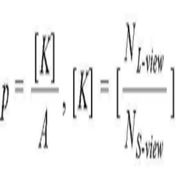
한편, 스위쳐블 배리어(30)의 배리어(B)는 제1 내지 제p(p는 자연수) 분할전극들을 포함한다. 스위쳐블 배리어(30)가 제1 및 제2 뷰 모드를 스위칭할 수 있으려면, 배리어(B)에는 수학식 1과 같이 p 개의 분할전극들이 필요하다.On the other hand, the barrier B of the
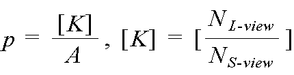
수학식 1에서, p는 배리어(B)에 포함된 분할전극들의 개수, NL-view는 제1 및 제2 뷰 모드의 뷰의 수 중 큰 수, NS-view는 제1 및 제2 뷰 모드의 뷰의 수 중 작은 수, [K]는 K를 q(q는 자연수) 배 하여 나올 수 있는 최소 정수, A는 스위쳐블 배리어(30)의 개구율을 의미한다. 예를 들어, 스위쳐블 배리어(30)가 제1 뷰 모드에서 2 뷰를 구현하고 제2 뷰 모드에서 4 뷰를 구현하는 경우, NL-view는 4가 되고, NS-view는 2가 되며, K는 2가 되고, [K]는 2가 된다. 따라서, 배리어(B)에 포함된 분할전극들의 개수인 p는 개구율이 25%인 경우, 8이 된다.In Equation (1), p is the number of divided electrodes included in the barrier (B), N L -view is the larger of the number of views in the first and second view modes, N S- (K) is the minimum integer that can be obtained by multiplying K by q (q is a natural number), and A represents the aperture ratio of the
제1 뷰 모드가 2 뷰로 구현되고, 제2 뷰 모드가 4 뷰로 구현되는 경우, 배리어(B)는 도 9a 및 도 9b와 같이 8개의 분할전극들(DE1~DE8)을 포함한다. 도 9a와 같이 제1 뷰 모드에서 표시패널(10)의 픽셀들은 2 뷰(view1, view2)를 표시하고, 제1 내지 제3 분할전극들(DE1~DE3)과 제6 내지 제8 분할전극들(DE6~DE8)은 배리어가 형성되도록 구동 전압을 공급받고, 제4 및 제5 분할전극들(DE4, DE5)은 배리어가 형성되지 않도록 구동 전압을 공급받는다. 도 9b와 같이 제2 뷰 모드에서 표시패널(10)의 픽셀들은 4 뷰(view1, view2, view3, view4)를 표시한다. 제2 뷰 모드에서 기수 배리어(Bo)의 제1 내지 제6 분할전극들(DE1~DE6)은 배리어가 형성되도록 구동 전압을 공급받고, 제7 및 제8 분할전극들(DE7, DE8)은 배리어가 형성되지 않도록 구동 전압을 공급받는다. 제2 뷰 모드에서 우수 배리어(Be)의 제3 내지 제8 분할전극들(DE3~DE8)은 배리어가 형성되도록 구동 전압을 공급받고, 제1 및 제2 분할전극들(DE1, DE2)은 배리어가 형성되지 않도록 구동 전압을 공급받는다.
When the first view mode is implemented in two views and the second view mode is implemented in four views, the barrier B includes eight divided electrodes DE1 to DE8 as shown in Figs. 9A and 9B. 9A, the pixels of the
도 10은 도 8의 룩-업 테이블에 저장된 2D 구동 전압 데이터, 제1 뷰 모드 구동 전압 데이터, 및 제2 뷰 모드 구동 전압 데이터를 보여주는 예시도면이다. 도 10을 참조하면, 2D 구동 전압 데이터, 제1 뷰 모드 구동 전압 데이터, 및 제2 뷰 모드 구동 전압 데이터에서 '0' 값은 배리어를 형성하지 않을 전압 레벨을 의미하고, '1' 값은 배리어를 형성할 전압 레벨을 의미한다. 또한, 2D 구동 전압 데이터, 제1 뷰 모드 구동 전압 데이터, 및 제2 뷰 모드 구동 전압 데이터는 서로 다르게 설정된다. 도 10과 같이, 2D 구동 전압 데이터의 입력 어드레스는 'H1'로 설정되고, 제1 뷰 모드 구동 전압 데이터는 'H2'로 설정되며, 제2 뷰 모드 구동 전압 데이터는 'H3'로 설정될 수 있다.10 is an exemplary view showing 2D driving voltage data, first view mode driving voltage data, and second view mode driving voltage data stored in the look-up table of FIG. Referring to FIG. 10, a '0' value in the 2D driving voltage data, a first view mode driving voltage data, and a second view mode driving voltage data indicates a voltage level at which no barrier is formed, As shown in FIG. Further, the 2D driving voltage data, the first view mode driving voltage data, and the second view mode driving voltage data are set differently from each other. 10, the input address of the 2D driving voltage data is set to 'H1', the first view mode driving voltage data is set to 'H2', and the second view mode driving voltage data is set to 'H3' have.
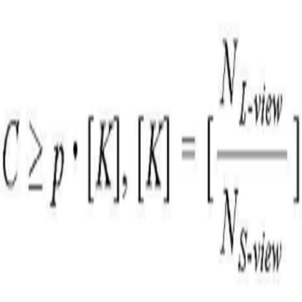
한편, 제1 뷰 모드가 2 뷰로 구현되고, 제2 뷰 모드가 4 뷰로 구현되는 경우, 룩-업 테이블(132)에 저장되는 2D 구동 전압 데이터, 제 1뷰 모드 구동 전압 데이터, 및 제2 뷰 모드 구동 전압 데이터의 크기(C)는 수학식 2와 같이 정의될 수 있다. 2D 구동 전압 데이터, 제 1뷰 모드 구동 전압 데이터, 및 제2 뷰 모드 구동 전압 데이터의 크기(C)의 단위는 비트(bits)이다.On the other hand, when the first view mode is implemented as two views and the second view mode is implemented as four views, the 2D drive voltage data, the first view mode drive voltage data, and the second view The magnitude (C) of the mode driving voltage data can be defined as shown in Equation (2). The units of the size (C) of the 2D driving voltage data, the first view mode driving voltage data, and the second view mode driving voltage data are bits.

수학식 2에서, C는 2D 구동 전압 데이터, 제 1뷰 모드 구동 전압 데이터, 및 제2 뷰 모드 구동 전압 데이터의 크기를 의미하고, p는 제1 내지 제m 배리어(B) 각각에 포함된 분할전극들의 수를 의미하며, NL - view는 제1 및 제2 뷰 모드의 뷰의 수 중 큰 수, NS - view는 제1 및 제2 뷰 모드의 뷰의 수 중 작은 수, [K]는 K를 q 배 하여 나올 수 있는 최소 정수를 의미한다. 예를 들어, 스위쳐블 배리어(30)가 제1 뷰 모드에서 2 뷰를 구현하고 제2 뷰 모드에서 4 뷰를 구현하는 경우, NL - view는 4가 되고, NS - view는 2가 되며, K는 2가 되고, [K]는 2가 된다. 따라서, 2D 구동 전압 데이터, 제 1뷰 모드 구동 전압 데이터, 및 제2 뷰 모드 구동 전압 데이터의 크기인 C는 최소 16비트(bits)로 설정될 수 있다.
In Equation (2), C denotes the size of the 2D driving voltage data, the first view mode driving voltage data, and the second view mode driving voltage data, and p denotes a division N L - view is a larger number of views of the first and second view modes, N S - view is a smaller number of views of the first and second view modes, [K] Is the minimum integer that can be multiplied by q. For example, if the
도 11은 본 발명의 실시예에 따른 입체영상 표시장치의 구동방법을 보여주는 흐름도이다. 본 발명의 실시예에 따른 입체영상 표시장치의 구동방법은 S201 내지 S206 단계를 포함한다.11 is a flowchart illustrating a method of driving a stereoscopic image display apparatus according to an exemplary embodiment of the present invention. The driving method of the stereoscopic image display apparatus according to the embodiment of the present invention includes steps S201 to S206.
첫 번째로, 호스트 시스템(160)은 2D 모드인지 3D 모드인지에 따라 모드 신호(MODE)를 발생한다. 2D 모드에서, 멀티뷰 영상 변환부(150)는 입력된 영상 데이터(RGB)를 그대로 출력하고, 스위쳐블 배리어 구동부(130)는 스위쳐블 배리어가 배리어를 형성하지 않도록 구동 전압을 다수의 분할전극들에 공급한다. (S201, S202)First, the
두 번째로, 3D 모드에서, 시청자 감지장치(170)는 시청자의 이미지를 저장하고, 도 얼굴 마스크(Facial mask) 기법 등을 이용하여 시청자의 수를 감지한다. 시청자 감지장치(170)는 시청자의 수를 포함한 시청자 감지정보를 호스트 시스템(160)으로 출력한다. (S203)Secondly, in the 3D mode, the
세 번째로, 호스트 시스템(160)은 시청자 수를 포함한 시청자 감지정보를 입력받고, 시청자 감지정보에 따라 최적 뷰의 수를 산출한다. 호스트 시스템(160)은 최적 뷰의 수에 따라 제1 및 제2 뷰 모드 중 어느 하나의 모드로 구동되도록 지시하는 뷰 제어신호(Cview)를 생성하여 스위쳐블 배리어 구동부(130)와 멀티뷰 영상 변환부(150)에 공급한다. 호스트 시스템(160)은 시청자 감지정보의 시청자 수를 입력 어드레스로 받고, 해당 입력 어드레스에 저장된 뷰의 수를 출력하는 룩-업 테이블을 이용하여 뷰 제어신호(Cview)를 생성할 수 있다. 예를 들어, 뷰 제어신호(Cview)는 제1 뷰 모드에서 로우 로직 레벨로 발생하고, 제2 뷰 모드에서 하이 로직 레벨로 발생할 수 있으나, 이에 한정되지 않음에 주의하여야 한다. (S204)Third, the
네 번째로, 멀티뷰 영상 변환부(150)는 3D 모드에서 뷰 제어신호(Cview)에 따라 제1 및 제2 뷰 모드 각각에서 미리 설정된 뷰의 수대로 입력된 영상 데이터를 멀티뷰 영상 데이터로 변환한다. 멀티뷰 영상 변환부(150)의 멀티뷰 영상 데이터 변환방법은 도 4, 도 5a 내지 도 5d, 도 6, 및 도 7을 결부하여 상세히 설명하였다. (S205)Fourth, the
다섯 번째로, 스위쳐블 배리어 구동부(130)는 3D 모드에서 뷰 제어신호(Cview)에 따라 제1 및 제2 뷰 모드 각각에서 미리 설정된 뷰의 수대로 배리어를 형성하도록 스위쳐블 배리어(30)의 분할전극(34)들에 구동 전압을 공급한다. 스위쳐블 배리어(30)와 스위쳐블 배리어 구동부(130)에 대하여는 도 8, 도 9, 도 10a 및 도 10b를 결부하여 상세히 설명하였다. (S206)
Fifthly, the
이상에서 살펴본 바와 같이, 본 발명은 시청자의 수를 파악하여 최적 뷰의 수를 설정하고, 입력된 영상 데이터를 미리 설정된 최적 뷰의 수에 따라 변환하며, 최적 설정된 뷰의 수에 따라 스위쳐블 배리어를 제어한다. 그 결과, 본 발명은 시청자의 수에 따라 입체영상의 뷰의 수를 다르게 제어할 수 있다. 이로 인해, 본 발명은 시청자의 수에 따라 입체영상의 해상도와 입체영상 품질을 최적으로 유지할 수 있다.As described above, according to the present invention, the number of viewers is determined, the number of optimal views is set, the input image data is converted according to the number of optimal views set in advance, and a switchable barrier . As a result, the number of views of the stereoscopic image can be controlled differently according to the number of viewers. Accordingly, the present invention can optimally maintain the resolution and the stereoscopic image quality of the stereoscopic image according to the number of viewers.
이상, 설명한 내용을 통해 당업자라면 본 발명의 기술사상을 일탈하지 아니하는 범위에서 다양한 변경 및 수정이 가능함을 알 수 있을 것이다. 따라서, 본 발명의 기술적 범위는 명세서의 상세한 설명에 기재된 내용으로 한정되는 것이 아니라 특허 청구의 범위에 의해 정하여져야만 할 것이다.
It will be apparent to those skilled in the art that various modifications and variations can be made in the present invention without departing from the spirit or scope of the invention. Therefore, the technical scope of the present invention should not be limited to the contents described in the detailed description of the specification, but should be defined by the claims.
10: 표시패널 30: 스위쳐블 배리어
31: 제1 기판 32: 제2 기판
33A: 제1 선편광자 33B: 제2 선편광자
34: 분할전극 35: 액정층
36: 공통전극 110: 게이트 구동부
120: 데이터 구동부 130: 스위쳐블 배리어 구동부
131: 스위쳐블 배리어 컨트롤러 132: 룩-업 테이블
133: 스위쳐블 배리어 전압 공급부 140: 타이밍 컨트롤러
150: 멀티뷰 영상 변환부 160: 호스트 시스템
170: 시청자 감지장치10: Display panel 30: Switchable barrier
31: first substrate 32: second substrate
33A:
34: split electrode 35: liquid crystal layer
36: common electrode 110: gate driver
120: Data driver 130: Switchable barrier driver
131: Switchable barrier controller 132: Look-up table
133: Switchable barrier voltage supply 140: Timing controller
150: Multi-view image conversion unit 160: Host system
170: viewer detection device
Claims (10)
시청자의 수를 감지하고 상기 시청자의 수를 포함하는 시청자 감지 정보를 출력하는 시청자 감지장치;
상기 시청자 감지 정보를 입력 받고 상기 시청자의 수를 근거로 제1 및 제2 뷰 모드 중 하나를 가리키는 뷰 제어신호를 출력하되, 상기 제1 및 제2 뷰 모드는 서로 다른 뷰의 수가 설정되는, 호스트 시스템;
상기 3D 모드에서 상기 뷰 제어신호가 가리키는 제1 또는 제2 뷰 모드에 설정된 뷰의 수대로 입력된 영상 데이터를 멀티뷰 영상 데이터로 변환하는 멀티뷰 영상 변환부;
상기 2D 모드에서 상기 표시패널에 상기 영상 데이터가 어드레싱되도록 제어하고, 3D 모드에서 상기 표시패널에 상기 멀티뷰 영상 데이터가 어드레싱되도록 제어하는 타이밍 컨트롤러;
2D 모드에서 상기 2D 영상을 통과시키고 상기 3D 모드에서 상기 멀티뷰 영상을 분리하도록 액정을 제어하여 상기 뷰 제어신호에 따라 복수 개의 배리어들을 형성하는 스위쳐블 배리어; 및
상기 2D 모드에서 배리어를 형성하지 않도록 상기 스위쳐블 배리어의 분할전극들에 구동 전압을 공급하고, 상기 3D 모드에서 상기 제1 뷰 모드에 형성되는 배리어들과 상기 제2 뷰 모드에 형성되는 배리어들의 크기와 중앙 위치를 서로 다르게 형성하도록 상기 스위쳐블 배리어의 분할전극들에 구동 전압을 공급하는 스위쳐블 배리어 구동부를 포함하고,
2개의 서브 픽셀의 너비에 포함된 분할전극들의 수 p는,
상기 A는 상기 스위쳐블 배리어의 개구율, 상기 [K]는 K를 q(q는 자연수) 배 하여 나올 수 있는 최소 정수, NL-view는 상기 제1 및 제2 뷰 모드의 뷰의 수 중 큰 수, NS-view는 상기 제1 및 제2 뷰 모드의 뷰의 수 중 작은 수를 의미하는 것을 특징으로 하는 입체영상 표시장치.A display panel for displaying the 2D image in the 2D mode and displaying the multi-view image in the 3D mode;
A viewer detecting device for detecting the number of viewers and outputting viewer detection information including the number of viewers;
Wherein the first view mode and the second view mode display a view control signal indicating one of a first view mode and a second view mode based on the number of viewers, system;
A multi-view image converter for converting the image data input in the first mode or the second view mode indicated by the view control signal into multi-view image data in the 3D mode;
A timing controller for controlling the image data to be addressed to the display panel in the 2D mode and controlling the multi-view image data to be addressed to the display panel in the 3D mode;
A switchable barrier for controlling the liquid crystal to pass the 2D image in a 2D mode and to separate the multi-view image in the 3D mode to form a plurality of barriers according to the view control signal; And
Wherein a driving voltage is supplied to the split electrodes of the switchable barrier so as not to form a barrier in the 2D mode, and a size of a barrier formed in the first view mode and a barrier formed in the second view mode in the 3D mode And a switchable barrier driver for supplying a driving voltage to the divided electrodes of the switchable barrier so as to form a central position different from each other,
The number p of split electrodes included in the width of two sub-
Wherein A is an aperture ratio of the switchable barrier, [K] is a minimum integer that can be obtained by multiplying K by q (q is a natural number), NL-view is a larger number of views of the first and second view modes And the NS-view means a smaller number of views of the first and second view modes.
상기 멀티뷰 영상 변환부는,
상기 입력된 영상 데이터로부터 뎁스 맵을 추출하고, 상기 뎁스 맵에서 입체감을 나타내는 뎁스를 이용하여 디스패러티를 산출하며, 상기 디스패러티를 적용하여 상기 3D 모드에서 상기 뷰 제어신호가 가리키는 제1 또는 제2 뷰 모드에 설정된 뷰의 수대로 제1 내지 제n(n은 자연수) 뷰 영상 데이터를 생성하고, 상기 제1 내지 제n 뷰 영상 데이터를 패널 뷰 맵에 따라 배열하여 멀티뷰 영상 데이터를 출력하는 것을 특징으로 하는 입체영상 표시장치.The method according to claim 1,
Wherein the multi-
A depth map extracting unit that extracts a depth map from the input image data, calculates a disparity using a depth indicating a depth sense in the depth map, and applies the disparity to calculate a first or second First to n-th (n is a natural number) view image data according to the number of views set in the view mode, and arranging the first to n-th view image data according to the panel view map to output multi-view image data Wherein the stereoscopic image display device is a stereoscopic image display device.
상기 패널 뷰 맵은 상기 제1 내지 제n 뷰 영상 데이터 각각을 수직으로 일렬로 배열하는 버티컬 뷰 맵 또는 상기 제1 내지 제n 뷰 영상 데이터 각각을 비스듬하게 사선으로 배열하는 슬랜티드 뷰 맵인 것을 특징으로 하는 입체영상 표시장치.The method of claim 3,
Wherein the panel view map is a vertical view map that vertically arranges the first to nth view image data or a slant view map that arranges the first to nth view image data obliquely and diagonally, Dimensional image display device.
상기 스위쳐블 배리어 구동부는,
2D 모드에서 공급되는 2D 구동 전압 데이터, 3D 모드의 제1 뷰 모드에서 공급되는 제1 뷰 모드 구동 전압 데이터, 3D 모드의 제2 뷰 모드에서 공급되는 제2 뷰 모드 구동 전압 데이터를 저장하는 룩-업 테이블;
상기 2D 모드에서 상기 룩-업 테이블의 2D 구동 전압 데이터를 출력하고, 상기 3D 모드의 제1 뷰 모드에서 상기 룩-업 테이블의 제1 뷰 모드 구동 전압 데이터를 출력하며, 상기 3D 모드의 제2 뷰 모드에서 상기 룩-업 테이블의 제2 뷰 모드 구동 전압 데이터를 출력하도록 제어하는 스위쳐블 배리어 컨트롤러; 및
상기 스위쳐블 배리어 컨트롤러의 제어 하에 상기 2D 모드, 3D 모드의 제1 뷰 모드, 및 3D 모드의 제2 뷰 모드에서 상기 스위쳐블 배리어에 구동 전압을 다르게 공급하는 스위쳐블 배리어 전압 공급부를 포함하는 것을 특징으로 하는 입체영상 표시장치.The method according to claim 1,
Wherein the switchable barrier driver comprises:
A second view mode driving voltage data supplied in the 2D mode, a first view mode driving voltage data supplied in the first view mode of the 3D mode, and a second view mode driving voltage data supplied in the second view mode of the 3D mode, Up table;
Up table in the 3D mode, outputs the 2D driving voltage data of the look-up table in the 2D mode, outputs the first view mode driving voltage data of the look-up table in the first view mode of the 3D mode, A switchable barrier controller for controlling to output second view mode drive voltage data of the look-up table in a view mode; And
And a switchable barrier voltage supply unit for supplying a drive voltage to the switchable barrier differently in the 2D mode, the first view mode of the 3D mode, and the second view mode of the 3D mode under the control of the switchable barrier controller Dimensional image display device.
상기 2D 구동 전압 데이터, 제1 뷰 모드 구동 전압 데이터, 상기 제2 뷰 모드 구동 전압 데이터의 크기 C는,
p는 2개의 서브 픽셀의 너비에 포함된 분할전극들의 수, NL-view는 상기 제1 및 제2 뷰 모드의 뷰의 수 중 큰 수, NS-view는 상기 제1 및 제2 뷰 모드의 뷰의 수 중 작은 수를 의미하는 것을 특징으로 하는 입체영상 표시장치.6. The method of claim 5,
The size C of the 2D driving voltage data, the first view mode driving voltage data,
p is the number of split electrodes included in the width of the two subpixels, NL-view is the larger of the number of views in the first and second view modes, NS-view is the view of the first and second view modes And the number of pixels of the three-dimensional image display device.
Priority Applications (4)
| Application Number | Priority Date | Filing Date | Title |
|---|---|---|---|
| KR1020110090667A KR101831652B1 (en) | 2011-09-07 | 2011-09-07 | Stereoscopic image display device and driving method thereof |
| TW101132076A TWI510054B (en) | 2011-09-07 | 2012-09-03 | Stereoscopic image display device and method for driving the same |
| US13/603,274 US8970582B2 (en) | 2011-09-07 | 2012-09-04 | Stereoscopic image display device and method for driving the same |
| CN201210330816.1A CN103002303B (en) | 2011-09-07 | 2012-09-07 | Stereoscopic image display device and method for driving the same |
Applications Claiming Priority (1)
| Application Number | Priority Date | Filing Date | Title |
|---|---|---|---|
| KR1020110090667A KR101831652B1 (en) | 2011-09-07 | 2011-09-07 | Stereoscopic image display device and driving method thereof |
Publications (2)
| Publication Number | Publication Date |
|---|---|
| KR20130027214A KR20130027214A (en) | 2013-03-15 |
| KR101831652B1 true KR101831652B1 (en) | 2018-02-26 |
Family
ID=47752806
Family Applications (1)
| Application Number | Title | Priority Date | Filing Date |
|---|---|---|---|
| KR1020110090667A Active KR101831652B1 (en) | 2011-09-07 | 2011-09-07 | Stereoscopic image display device and driving method thereof |
Country Status (4)
| Country | Link |
|---|---|
| US (1) | US8970582B2 (en) |
| KR (1) | KR101831652B1 (en) |
| CN (1) | CN103002303B (en) |
| TW (1) | TWI510054B (en) |
Families Citing this family (23)
| Publication number | Priority date | Publication date | Assignee | Title |
|---|---|---|---|---|
| US9100642B2 (en) * | 2011-09-15 | 2015-08-04 | Broadcom Corporation | Adjustable depth layers for three-dimensional images |
| KR102052153B1 (en) * | 2013-02-15 | 2019-12-17 | 삼성전자주식회사 | Mobile terminal for controlling a hearing aid and method therefor |
| KR101981530B1 (en) * | 2013-03-29 | 2019-05-23 | 엘지디스플레이 주식회사 | Stereoscopic image display device and method for driving the same |
| CN103399427B (en) * | 2013-08-21 | 2016-02-24 | 福州大学 | The 3 d display device that a kind of viewpoint number is controlled |
| KR102164958B1 (en) * | 2013-11-11 | 2020-10-14 | 삼성디스플레이 주식회사 | Three-dimensional image display apparatus |
| WO2015072193A1 (en) * | 2013-11-15 | 2015-05-21 | シャープ株式会社 | Display device |
| US10453371B2 (en) | 2014-02-07 | 2019-10-22 | Samsung Electronics Co., Ltd. | Multi-layer display with color and contrast enhancement |
| US10565925B2 (en) | 2014-02-07 | 2020-02-18 | Samsung Electronics Co., Ltd. | Full color display with intrinsic transparency |
| US10375365B2 (en) | 2014-02-07 | 2019-08-06 | Samsung Electronics Co., Ltd. | Projection system with enhanced color and contrast |
| US10554962B2 (en) * | 2014-02-07 | 2020-02-04 | Samsung Electronics Co., Ltd. | Multi-layer high transparency display for light field generation |
| KR102192986B1 (en) * | 2014-05-23 | 2020-12-18 | 삼성전자주식회사 | Image display apparatus and method for displaying image |
| KR102197382B1 (en) * | 2014-08-14 | 2020-12-31 | 엘지디스플레이 주식회사 | Bendable stereoscopic 3d display device |
| KR102334031B1 (en) * | 2014-11-03 | 2021-12-01 | 엘지디스플레이 주식회사 | Autostereoscopic 3d display device and driving method thereof |
| EP3041231A1 (en) * | 2014-12-30 | 2016-07-06 | SeeFront GmbH | Autostereoscopic multi-view system |
| US20170171535A1 (en) * | 2015-12-09 | 2017-06-15 | Hyundai Motor Company | Three-dimensional display apparatus and method for controlling the same |
| WO2017188955A1 (en) * | 2016-04-28 | 2017-11-02 | Hewlett-Packard Development Company, L.P. | Digital display devices |
| KR102056677B1 (en) * | 2017-09-07 | 2019-12-17 | 엘지디스플레이 주식회사 | Stereoscopic Display device having a barrier panel |
| CN108254932B (en) * | 2018-01-31 | 2020-11-13 | 京东方科技集团股份有限公司 | Display device and control method thereof |
| WO2020091816A1 (en) * | 2018-11-01 | 2020-05-07 | Leia Inc. | Contextual lightfield display system, multiview display, and method |
| WO2020219400A1 (en) | 2019-04-22 | 2020-10-29 | Leia Inc. | Time-multiplexed backlight, multiview display, and method |
| CN112188181B (en) * | 2019-07-02 | 2023-07-04 | 中强光电股份有限公司 | Image display device, stereoscopic image processing circuit and synchronization signal correction method thereof |
| KR102878048B1 (en) * | 2019-12-20 | 2025-10-30 | 엘지디스플레이 주식회사 | Display Device |
| CN117083852A (en) * | 2021-04-04 | 2023-11-17 | 镭亚股份有限公司 | Multi-view image creation system and method |
Citations (1)
| Publication number | Priority date | Publication date | Assignee | Title |
|---|---|---|---|---|
| JP2011081269A (en) * | 2009-10-08 | 2011-04-21 | Nikon Corp | Image display device and image display method |
Family Cites Families (8)
| Publication number | Priority date | Publication date | Assignee | Title |
|---|---|---|---|---|
| US6437914B1 (en) * | 1997-01-29 | 2002-08-20 | Thomson Licensing S.A. | Projection televisions with holographic screens having center to edge variations |
| US6239830B1 (en) * | 1998-01-21 | 2001-05-29 | New York University | Displayer and method for displaying |
| US6574043B2 (en) * | 2001-11-07 | 2003-06-03 | Eastman Kodak Company | Method for enhanced bit depth in an imaging apparatus using a spatial light modulator |
| JP3973525B2 (en) * | 2002-09-24 | 2007-09-12 | シャープ株式会社 | Electronic device having 2D (2D) and 3D (3D) display functions |
| KR20050050338A (en) * | 2003-11-25 | 2005-05-31 | 주식회사 팬택앤큐리텔 | Apparatus and method for displaying hologram of mobile communication terminal |
| KR100893616B1 (en) | 2006-04-17 | 2009-04-20 | 삼성모바일디스플레이주식회사 | Electronic video equipment, 2D / 3D video display device and driving method thereof |
| WO2008020399A1 (en) * | 2006-08-17 | 2008-02-21 | Koninklijke Philips Electronics N.V. | Display device |
| KR101697184B1 (en) * | 2010-04-20 | 2017-01-17 | 삼성전자주식회사 | Apparatus and Method for generating mesh, and apparatus and method for processing image |
-
2011
- 2011-09-07 KR KR1020110090667A patent/KR101831652B1/en active Active
-
2012
- 2012-09-03 TW TW101132076A patent/TWI510054B/en active
- 2012-09-04 US US13/603,274 patent/US8970582B2/en active Active
- 2012-09-07 CN CN201210330816.1A patent/CN103002303B/en active Active
Patent Citations (1)
| Publication number | Priority date | Publication date | Assignee | Title |
|---|---|---|---|---|
| JP2011081269A (en) * | 2009-10-08 | 2011-04-21 | Nikon Corp | Image display device and image display method |
Also Published As
| Publication number | Publication date |
|---|---|
| US8970582B2 (en) | 2015-03-03 |
| KR20130027214A (en) | 2013-03-15 |
| TW201316751A (en) | 2013-04-16 |
| CN103002303A (en) | 2013-03-27 |
| TWI510054B (en) | 2015-11-21 |
| US20130057575A1 (en) | 2013-03-07 |
| CN103002303B (en) | 2015-03-11 |
Similar Documents
| Publication | Publication Date | Title |
|---|---|---|
| KR101831652B1 (en) | Stereoscopic image display device and driving method thereof | |
| KR101279128B1 (en) | Stereoscopic image display and driving method thereof | |
| US8878842B2 (en) | Stereoscopic image display device and method for driving the same | |
| KR101323468B1 (en) | Stereoscopic image display device and drving method thereof | |
| KR101330412B1 (en) | 3d image display device and driving method thereof | |
| US8743111B2 (en) | Stereoscopic image display and method for driving the same | |
| KR101869872B1 (en) | Method of multi-view image formation and stereoscopic image display device using the same | |
| KR20110050178A (en) | Stereoscopic Display and Driving Method | |
| KR101981530B1 (en) | Stereoscopic image display device and method for driving the same | |
| KR101840876B1 (en) | Stereoscopic image display device and driving method thereof | |
| KR101793283B1 (en) | Jagging improvement method and stereoscopic image display device using the same | |
| KR101296902B1 (en) | Image processing unit and stereoscopic image display device using the same, and image processing method | |
| KR20130061290A (en) | Method of multi-view image formation and stereoscopic image display device using the same | |
| KR101763935B1 (en) | Stereoscopic image display and driving method thereof | |
| KR101843197B1 (en) | Method of multi-view image formation and stereoscopic image display device using the same | |
| KR102089323B1 (en) | Method of multi-view image formation and stereoscopic image display device using the same | |
| KR101843198B1 (en) | Method of multi-view image formation and stereoscopic image display device using the same | |
| US8723931B2 (en) | Stereoscopic image display | |
| KR101863140B1 (en) | Display Apparatus For Displaying Three Dimensional Picture And Driving Method For The Same | |
| KR101829466B1 (en) | Stereoscopic image display device | |
| KR20130012672A (en) | Stereoscopic image display device and driving method thereof | |
| KR101800886B1 (en) | Stereoscopic image display device and driving method thereof | |
| KR20120003758A (en) | Scanning backlight driving method and 3D image display device using the same |
Legal Events
| Date | Code | Title | Description |
|---|---|---|---|
| PA0109 | Patent application |
Patent event code: PA01091R01D Comment text: Patent Application Patent event date: 20110907 |
|
| PG1501 | Laying open of application | ||
| A201 | Request for examination | ||
| PA0201 | Request for examination |
Patent event code: PA02012R01D Patent event date: 20160905 Comment text: Request for Examination of Application Patent event code: PA02011R01I Patent event date: 20110907 Comment text: Patent Application |
|
| E902 | Notification of reason for refusal | ||
| PE0902 | Notice of grounds for rejection |
Comment text: Notification of reason for refusal Patent event date: 20170926 Patent event code: PE09021S01D |
|
| E701 | Decision to grant or registration of patent right | ||
| PE0701 | Decision of registration |
Patent event code: PE07011S01D Comment text: Decision to Grant Registration Patent event date: 20180207 |
|
| GRNT | Written decision to grant | ||
| PR0701 | Registration of establishment |
Comment text: Registration of Establishment Patent event date: 20180219 Patent event code: PR07011E01D |
|
| PR1002 | Payment of registration fee |
Payment date: 20180220 End annual number: 3 Start annual number: 1 |
|
| PG1601 | Publication of registration | ||
| PR1001 | Payment of annual fee |
Payment date: 20210118 Start annual number: 4 End annual number: 4 |
|
| PR1001 | Payment of annual fee |
Payment date: 20220120 Start annual number: 5 End annual number: 5 |
|
| PR1001 | Payment of annual fee |
Payment date: 20230116 Start annual number: 6 End annual number: 6 |
|
| PR1001 | Payment of annual fee |
Payment date: 20240115 Start annual number: 7 End annual number: 7 |
|
| PR1001 | Payment of annual fee |
Payment date: 20250115 Start annual number: 8 End annual number: 8 |