KR101811829B1 - Switching apparatus, magnetic resonance imaging apparatus including the same, and controlling method for the magnetic resonance imaging apparatus - Google Patents
Switching apparatus, magnetic resonance imaging apparatus including the same, and controlling method for the magnetic resonance imaging apparatus Download PDFInfo
- Publication number
- KR101811829B1 KR101811829B1 KR1020150169921A KR20150169921A KR101811829B1 KR 101811829 B1 KR101811829 B1 KR 101811829B1 KR 1020150169921 A KR1020150169921 A KR 1020150169921A KR 20150169921 A KR20150169921 A KR 20150169921A KR 101811829 B1 KR101811829 B1 KR 101811829B1
- Authority
- KR
- South Korea
- Prior art keywords
- switching
- output
- channels
- connection relationship
- mode
- Prior art date
Links
- 238000002595 magnetic resonance imaging Methods 0.000 title claims abstract description 37
- 238000000034 method Methods 0.000 title claims abstract description 23
- 238000010586 diagram Methods 0.000 description 14
- 238000001208 nuclear magnetic resonance pulse sequence Methods 0.000 description 8
- 230000005540 biological transmission Effects 0.000 description 7
- 230000003068 static effect Effects 0.000 description 7
- 238000013500 data storage Methods 0.000 description 5
- 125000004435 hydrogen atom Chemical class [H]* 0.000 description 5
- 230000005415 magnetization Effects 0.000 description 4
- 125000004429 atom Chemical group 0.000 description 3
- 238000005255 carburizing Methods 0.000 description 2
- 238000005520 cutting process Methods 0.000 description 2
- 238000002059 diagnostic imaging Methods 0.000 description 2
- 238000003384 imaging method Methods 0.000 description 2
- 238000004519 manufacturing process Methods 0.000 description 2
- 230000010363 phase shift Effects 0.000 description 2
- 238000000264 spin echo pulse sequence Methods 0.000 description 2
- 238000005481 NMR spectroscopy Methods 0.000 description 1
- 210000001015 abdomen Anatomy 0.000 description 1
- 210000000481 breast Anatomy 0.000 description 1
- 210000000038 chest Anatomy 0.000 description 1
- 238000003745 diagnosis Methods 0.000 description 1
- 230000000694 effects Effects 0.000 description 1
- 230000005284 excitation Effects 0.000 description 1
- 229910052739 hydrogen Inorganic materials 0.000 description 1
- 239000001257 hydrogen Substances 0.000 description 1
- 230000005865 ionizing radiation Effects 0.000 description 1
- 210000003127 knee Anatomy 0.000 description 1
- 210000002414 leg Anatomy 0.000 description 1
- 210000004872 soft tissue Anatomy 0.000 description 1
- 238000003860 storage Methods 0.000 description 1
- 239000000126 substance Substances 0.000 description 1
- 230000002194 synthesizing effect Effects 0.000 description 1
- 238000003325 tomography Methods 0.000 description 1
- 238000002604 ultrasonography Methods 0.000 description 1
Images


Classifications
-
- A—HUMAN NECESSITIES
- A61—MEDICAL OR VETERINARY SCIENCE; HYGIENE
- A61B—DIAGNOSIS; SURGERY; IDENTIFICATION
- A61B5/00—Measuring for diagnostic purposes; Identification of persons
- A61B5/05—Detecting, measuring or recording for diagnosis by means of electric currents or magnetic fields; Measuring using microwaves or radio waves
- A61B5/055—Detecting, measuring or recording for diagnosis by means of electric currents or magnetic fields; Measuring using microwaves or radio waves involving electronic [EMR] or nuclear [NMR] magnetic resonance, e.g. magnetic resonance imaging
-
- G—PHYSICS
- G01—MEASURING; TESTING
- G01R—MEASURING ELECTRIC VARIABLES; MEASURING MAGNETIC VARIABLES
- G01R33/00—Arrangements or instruments for measuring magnetic variables
- G01R33/20—Arrangements or instruments for measuring magnetic variables involving magnetic resonance
- G01R33/28—Details of apparatus provided for in groups G01R33/44 - G01R33/64
- G01R33/32—Excitation or detection systems, e.g. using radio frequency signals
- G01R33/36—Electrical details, e.g. matching or coupling of the coil to the receiver
- G01R33/3664—Switching for purposes other than coil coupling or decoupling, e.g. switching between a phased array mode and a quadrature mode, switching between surface coil modes of different geometrical shapes, switching from a whole body reception coil to a local reception coil or switching for automatic coil selection in moving table MR or for changing the field-of-view
-
- A—HUMAN NECESSITIES
- A61—MEDICAL OR VETERINARY SCIENCE; HYGIENE
- A61B—DIAGNOSIS; SURGERY; IDENTIFICATION
- A61B5/00—Measuring for diagnostic purposes; Identification of persons
- A61B5/0033—Features or image-related aspects of imaging apparatus, e.g. for MRI, optical tomography or impedance tomography apparatus; Arrangements of imaging apparatus in a room
-
- G—PHYSICS
- G01—MEASURING; TESTING
- G01R—MEASURING ELECTRIC VARIABLES; MEASURING MAGNETIC VARIABLES
- G01R33/00—Arrangements or instruments for measuring magnetic variables
- G01R33/20—Arrangements or instruments for measuring magnetic variables involving magnetic resonance
- G01R33/28—Details of apparatus provided for in groups G01R33/44 - G01R33/64
- G01R33/32—Excitation or detection systems, e.g. using radio frequency signals
- G01R33/36—Electrical details, e.g. matching or coupling of the coil to the receiver
Landscapes
- Physics & Mathematics (AREA)
- Health & Medical Sciences (AREA)
- Condensed Matter Physics & Semiconductors (AREA)
- General Physics & Mathematics (AREA)
- Life Sciences & Earth Sciences (AREA)
- Nuclear Medicine, Radiotherapy & Molecular Imaging (AREA)
- Engineering & Computer Science (AREA)
- Medical Informatics (AREA)
- Heart & Thoracic Surgery (AREA)
- Radiology & Medical Imaging (AREA)
- Veterinary Medicine (AREA)
- Biophysics (AREA)
- Pathology (AREA)
- Biomedical Technology (AREA)
- Public Health (AREA)
- General Health & Medical Sciences (AREA)
- Molecular Biology (AREA)
- Surgery (AREA)
- Animal Behavior & Ethology (AREA)
- Magnetic Resonance Imaging Apparatus (AREA)
- High Energy & Nuclear Physics (AREA)
- Signal Processing (AREA)
Abstract
입력채널 및 선택된 모드에 따라 결정되는 출력채널 그룹의 연결관계를 스위칭하는 스위칭 장치, 이를 포함하는 자기공명영상장치, 및 자기공명영상장치의 제어방법을 제공한다.
일 실시예에 따른 스위칭 장치는, 자기장이 인가된 대상체로부터 RF 신호를 수신하는 복수의 코일 각각과 접속 가능한 복수의 입력채널; 상기 수신된 RF 신호를 기초로 자기공명영상을 생성하는 영상처리부와 접속 가능한 복수의 출력채널; 및 상기 복수의 입력채널 및 상기 복수의 출력채널 간의 연결관계를 스위칭하는 스위칭부; 를 포함하고, 상기 스위칭부는, 제 1 모드가 선택되면 상기 복수의 출력채널 전체로 구성되는 제 1 출력채널 그룹이 상기 RF 신호를 출력하도록 상기 연결관계를 스위칭하고, 제 2 모드가 선택되면 상기 복수의 출력채널 중 미리 정해진 일부로 구성되는 제 2 출력채널 그룹이 상기 RF 신호를 출력하도록 상기 연결관계를 스위칭할 수 있다.A switching device for switching a connection relationship of an output channel group determined according to an input channel and a selected mode, a magnetic resonance imaging device including the switching device, and a control method of the magnetic resonance imaging device.
According to one embodiment, a switching device includes: a plurality of input channels connectable to a plurality of coils receiving an RF signal from a target object to which a magnetic field is applied; A plurality of output channels connectable to an image processing unit for generating a magnetic resonance image based on the received RF signal; And a switching unit switching the connection relationship between the plurality of input channels and the plurality of output channels. Wherein when the first mode is selected, the switching unit switches the connection relationship such that a first output channel group composed of the plurality of output channels as a whole outputs the RF signal, and when the second mode is selected, A second output channel group composed of a predetermined part of the output channels of the first output channel may output the RF signal.

Description
RF신호가 입출력되는 입력채널과 출력채널의 연결관계를 스위칭하는 스위칭 장치, 이를 포함하는 자기공명영상장치, 및 자기공명영상장치의 제어방법에 관한 것이다.A switching device for switching a connection relationship between an input channel and an output channel through which an RF signal is input and output, a magnetic resonance imaging apparatus including the switching device, and a control method of the magnetic resonance imaging apparatus.
일반적으로 의료용 영상 장치는 환자의 정보를 획득하여 영상을 제공하는 장치이다. 의료용 영상 장치는 X선 장치, 초음파 진단 장치, 컴퓨터 단층 촬영 장치, 자기공명영상장치 등이 있다. Generally, a medical imaging apparatus is a device for acquiring information of a patient and providing an image. Medical imaging devices include X-ray devices, ultrasound diagnostic devices, computerized tomography devices, and magnetic resonance imaging devices.
이 중에서 자기공명영상장치는 영상 촬영 조건이 상대적으로 자유롭고, 연부 조직에서의 우수한 대조도와 다양한 진단 정보 영상을 제공해주기 때문에 의료용 영상을 이용한 진단 분야에서 중요한 위치를 차지하고 있다. Among them, the MRI apparatus is relatively free from the imaging conditions, provides excellent contrast in soft tissues, and provides various diagnostic information images, thus occupying an important position in diagnosis using medical images.
자기공명영상(Magnetic Resonance Imaging, MRI)은 인체에 해가 없는 자장과 비전리 방사선인 RF를 이용하여 체내의 수소 원자핵에 핵자기 공명 현상을 일으켜 원자핵의 밀도 및 물리화학적 특성을 영상화한 것이다.Magnetic Resonance Imaging (MRI) is the imaging of the atomic nucleus density and physico-chemical properties by causing nuclear magnetic resonance in the hydrogen nucleus in the body using a magnetic field free from harmless human body and RF, non-ionizing radiation.
구체적으로, 자기공명영상장치는 갠트리 내부에 일정한 자기장을 가한 상태에서 일정한 주파수와 에너지를 공급하여 원자핵으로부터 방출된 에너지를 신호로 변환하여 대상체 내부를 영상화한다.Specifically, a magnetic resonance imaging apparatus applies a constant magnetic field to a gantry, applies a constant frequency and energy, and converts energy emitted from an atomic nucleus into a signal to image the interior of the object.
이 때, 원자핵으로부터 방출된 에너지를 수신하기 위해 RF 코일이 이용되는데, RF 코일은 환자 테이블과 분리된 형태로 마련될 수 있다. 일반적으로 이러한 RF 코일은 평상시에는 환자 테이블과 분리되어 보관되다가, 자기공명영상 촬영 시에 환자 테이블과 연결되어 사용될 수 있다.At this time, an RF coil is used to receive the energy emitted from the nucleus, and the RF coil may be provided separately from the patient table. Generally, these RF coils are stored separately from the patient table at normal times, and can be used in connection with the patient table at the time of magnetic resonance imaging.
개시된 발명의 일 실시예에 따르면, 입력채널 및 선택된 모드에 따라 결정되는 출력채널 그룹의 연결관계를 스위칭하는 스위칭 장치, 이를 포함하는 자기공명영상장치, 및 자기공명영상장치의 제어방법을 제공한다.According to an embodiment of the present invention, there is provided a switching device for switching a connection relationship between an input channel and an output channel group determined according to a selected mode, a magnetic resonance imaging apparatus including the same, and a method for controlling the magnetic resonance imaging apparatus.
일 실시예에 따른 스위칭 장치는, 자기장이 인가된 대상체로부터 RF 신호를 수신하는 복수의 코일 각각과 접속 가능한 복수의 입력채널; 상기 수신된 RF 신호를 기초로 자기공명영상을 생성하는 영상처리부와 접속 가능한 복수의 출력채널; 및 상기 복수의 입력채널 및 상기 복수의 출력채널 간의 연결관계를 스위칭하는 스위칭부; 를 포함하고, 상기 스위칭부는, 제 1 모드가 선택되면 상기 복수의 출력채널 전체로 구성되는 제 1 출력채널 그룹이 상기 RF 신호를 출력하도록 상기 연결관계를 스위칭하고, 제 2 모드가 선택되면 상기 복수의 출력채널 중 미리 정해진 일부로 구성되는 제 2 출력채널 그룹이 상기 RF 신호를 출력하도록 상기 연결관계를 스위칭할 수 있다.According to one embodiment, a switching device includes: a plurality of input channels connectable to a plurality of coils receiving an RF signal from a target object to which a magnetic field is applied; A plurality of output channels connectable to an image processing unit for generating a magnetic resonance image based on the received RF signal; And a switching unit switching the connection relationship between the plurality of input channels and the plurality of output channels. Wherein when the first mode is selected, the switching unit switches the connection relationship such that a first output channel group composed of the plurality of output channels as a whole outputs the RF signal, and when the second mode is selected, A second output channel group composed of a predetermined part of the output channels of the first output channel may output the RF signal.
또한, 상기 제 1 출력채널 그룹을 구성하는 출력채널 개수는, 상기 제 2 출력채널 그룹을 구성하는 출력채널 개수의 두 배이고, 상기 복수의 입력채널의 개수는, 상기 제 1 출력채널 그룹을 구성하는 출력채널 개수의 두 배일 수 있다.The number of output channels constituting the first output channel group is twice the number of output channels constituting the second output channel group, and the number of the plurality of input channels constitutes the first output channel group It can be twice the number of output channels.
또한, 상기 스위칭부는, 여덟 개의 입력채널 및 네 개의 출력채널 간의 연결관계를 스위칭하는 복수의 스위칭셀; 을 포함할 수 있다.The switching unit may include: a plurality of switching cells for switching connection relationships between eight input channels and four output channels; . ≪ / RTI >
또한, 상기 스위칭셀은, 상기 제 1 모드가 선택되면 상기 네 개의 출력채널 전체로 구성되는 상기 제 1 출력채널 그룹이 상기 RF 신호를 출력하도록 상기 연결관계를 스위칭하고, 상기 제 2 모드가 선택되면 상기 네 개의 출력채널 중 두 개로 구성되는 상기 제 2 출력채널 그룹이 상기 RF 신호를 출력하도록 상기 연결관계를 스위칭할 수 있다.If the first mode is selected, the switching cell switches the connection relationship such that the first output channel group formed of the entire four output channels outputs the RF signal, and when the second mode is selected And switch the connection relationship such that the second output channel group consisting of two of the four output channels output the RF signal.
또한, 상기 스위칭셀은, 상기 여덟 개의 입력채널과 연결되는 1 차 입력채널 및 네 개의 1차 출력채널의 연결관계를 스위칭하는 1 차 스위칭부; 및 상기 제 1 모드가 선택되면 상기 네 개의 1차 출력채널과 상기 제 1 출력채널 그룹의 연결관계를 스위칭하고, 상기 제 2 모드가 선택되면 상기 네 개의 1차 출력채널과 상기 제 2 출력채널 그룹의 연결관계를 스위칭하는 2차 스위칭부; 를 포함할 수 있다.The switching cell may include a primary switching unit for switching a connection relationship between a primary input channel connected to the eight input channels and four primary output channels; And switching the connection relationship between the four primary output channels and the first output channel group if the first mode is selected and switching the connection relationship between the four primary output channels and the second output channel group if the second mode is selected, A secondary switching unit for switching a connection relationship between the first and second switching units; . ≪ / RTI >
또한, 상기 1차 스위칭부는, 상기 1차 입력채널 중 어느 네 개 및 상기 1차 출력채널 중 어느 두 개의 연결관계를 스위칭하는 제 1 하위 스위칭부; 및 상기 1차 입력채널 중 나머지 네 개 및 상기 1 차 출력채널 중 나머지 두 개의 연결관계를 스위칭하는 제 2 하위 스위칭부; 를 포함할 수 있다.The primary switching unit may include: a first lower switching unit for switching connection relations of any four of the primary input channels and the primary output channel; And a second lower switching unit for switching the connection relationship of the remaining four of the primary input channels and the remaining two of the primary output channels; . ≪ / RTI >
또한, 상기 2차 스위칭부는, 상기 제 2 모드가 선택되면, 상기 네 개의 1 차 출력채널과 연결되는 2 차 입력채널 및 상기 제 2 출력채널 그룹과 연결되는 두 개의 2 차 출력채널의 연결관계를 스위칭하는 제 3 하위 스위칭부; 를 포함할 수 있다.When the second mode is selected, the secondary switching unit switches the connection relationship between the secondary input channel connected to the four primary output channels and the two secondary output channels connected to the second output channel group A third lower switching unit for switching; . ≪ / RTI >
또한, 상기 2차 스위칭부는, 상기 제 1 모드가 선택되면, 상기 네 개의 1 차 출력채널과 상기 제 1 출력채널 그룹을 연결하는 모드 선택부; 를 더 포함할 수 있다.In addition, the secondary switching unit may include: a mode selection unit for connecting the four primary output channels and the first output channel group when the first mode is selected; As shown in FIG.
일 실시예에 따른 자기공명영상장치는, 자기장이 인가된 대상체로부터 RF 신호를 수신하는 복수의 코일이 배열되는 RF 코일; 상기 수신된 RF 신호를 기초로 자기공명영상을 생성하는 영상처리부; 및 상기 복수의 코일과 접속 가능한 복수의 입력채널 및 상기 영상처리부와 접속가능한 복수의 출력채널 간의 연결관계를 스위칭하는 스위칭 장치; 를 포함하고, 상기 스위칭 장치는, 제 1 모드가 선택되면 상기 복수의 출력채널 전체로 구성되는 제 1 출력채널 그룹이 상기 RF 신호를 출력하도록 상기 연결관계를 스위칭하고, 제 2 모드가 선택되면 상기 복수의 출력채널 중 미리 정해진 일부로 구성되는 제 2 출력채널 그룹이 상기 RF 신호를 출력하도록 상기 연결관계를 스위칭할 수 있다.A magnetic resonance imaging apparatus according to an embodiment includes an RF coil in which a plurality of coils for receiving an RF signal from a target object to which a magnetic field is applied are arranged; An image processor for generating a magnetic resonance image based on the received RF signal; And a switching device for switching a connection relationship between a plurality of input channels connectable with the plurality of coils and a plurality of output channels connectable with the image processing unit; Wherein when the first mode is selected, the switching device switches the connection relationship such that a first output channel group composed of all of the plurality of output channels outputs the RF signal, and when the second mode is selected, And switch the connection relationship such that a second output channel group composed of a predetermined one of a plurality of output channels outputs the RF signal.
또한, 상기 제 1 출력채널 그룹을 구성하는 출력채널 개수는, 상기 제 2 출력채널 그룹을 구성하는 출력채널 개수의 두 배이고, 상기 복수의 입력채널의 개수는, 상기 제 1 출력채널 그룹을 구성하는 출력채널 개수의 두 배일 수 있다.The number of output channels constituting the first output channel group is twice the number of output channels constituting the second output channel group, and the number of the plurality of input channels constitutes the first output channel group It can be twice the number of output channels.
또한, 상기 스위칭 장치는, 여덟 개의 입력채널 및 네 개의 출력채널 간의 연결관계를 스위칭하는 복수의 스위칭셀; 을 포함할 수 있다.The switching device may further include: a plurality of switching cells for switching connection relationships between the eight input channels and the four output channels; . ≪ / RTI >
또한, 상기 스위칭셀은, 상기 제 1 모드가 선택되면 상기 네 개의 출력채널 전체로 구성되는 상기 제 1 출력채널 그룹이 상기 RF 신호를 출력하도록 상기 연결관계를 스위칭하고, 상기 제 2 모드가 선택되면 상기 네 개의 출력채널 중 두 개로 구성되는 상기 제 2 출력채널 그룹이 상기 RF 신호를 출력하도록 상기 연결관계를 스위칭할 수 있다.If the first mode is selected, the switching cell switches the connection relationship such that the first output channel group formed of the entire four output channels outputs the RF signal, and when the second mode is selected And switch the connection relationship such that the second output channel group consisting of two of the four output channels output the RF signal.
또한, 상기 스위칭셀은, 상기 여덟 개의 입력채널과 연결되는 1 차 입력채널 및 네 개의 1차 출력채널의 연결관계를 스위칭하는 1 차 스위칭부; 및 상기 제 1 모드가 선택되면 상기 네 개의 1차 출력채널과 상기 제 1 출력채널 그룹의 연결관계를 스위칭하고, 상기 제 2 모드가 선택되면 상기 네 개의 1차 출력채널과 상기 제 2 출력채널 그룹의 연결관계를 스위칭하는 2차 스위칭부; 를 포함할 수 있다.The switching cell may include a primary switching unit for switching a connection relationship between a primary input channel connected to the eight input channels and four primary output channels; And switching the connection relationship between the four primary output channels and the first output channel group if the first mode is selected and switching the connection relationship between the four primary output channels and the second output channel group if the second mode is selected, A secondary switching unit for switching a connection relationship between the first and second switching units; . ≪ / RTI >
또한, 상기 1차 스위칭부는, 상기 1차 입력채널 중 어느 네 개 및 상기 1차 출력채널 중 어느 두 개의 연결관계를 스위칭하는 제 1 하위 스위칭부; 및 상기 1차 입력채널 중 나머지 네 개 및 상기 1 차 출력채널 중 나머지 두 개의 연결관계를 스위칭하는 제 2 하위 스위칭부; 를 포함할 수 있다.The primary switching unit may include: a first lower switching unit for switching connection relations of any four of the primary input channels and the primary output channel; And a second lower switching unit for switching the connection relationship of the remaining four of the primary input channels and the remaining two of the primary output channels; . ≪ / RTI >
또한, 상기 2차 스위칭부는, 상기 제 2 모드가 선택되면, 상기 네 개의 1 차 출력채널과 연결되는 2 차 입력채널 및 상기 제 2 출력채널 그룹과 연결되는 두 개의 2 차 출력채널의 연결관계를 스위칭하는 제 3 하위 스위칭부; 를 포함할 수 있다.When the second mode is selected, the secondary switching unit switches the connection relationship between the secondary input channel connected to the four primary output channels and the two secondary output channels connected to the second output channel group A third lower switching unit for switching; . ≪ / RTI >
또한, 상기 2차 스위칭부는, 상기 제 1 모드가 선택되면, 상기 네 개의 1 차 출력채널과 상기 제 1 출력채널 그룹을 연결하는 모드 선택부; 를 더 포함할 수 있다.In addition, the secondary switching unit may include: a mode selection unit for connecting the four primary output channels and the first output channel group when the first mode is selected; As shown in FIG.
일 실시예에 따른 자기공명영상장치의 제어방법은, 대상체의 RF 신호를 수신하는 복수의 코일과 접속 가능한 복수의 입력채널 및 상기 수신된 RF 신호를 기초로 자기공명영상을 생성하는 영상처리부와 접속 가능한 복수의 출력채널 간의 연결관계를 스위칭하는 스위칭 장치; 를 포함하는 자기공명영상장치에 있어서, 상기 스위칭 장치의 선택된 모드를 확인하는 단계; 및 상기 선택된 모드에 따라 상기 연결관계를 스위칭하는 단계; 를 포함하고, 상기 연결관계를 스위칭하는 단계는, 상기 스위칭 장치가 제 1 모드로 선택되면, 상기 복수의 출력채널 전체로 구성되는 제 1 출력채널 그룹이 상기 RF 신호를 출력하도록 상기 연결관계를 스위칭하는 단계; 및 상기 스위칭 장치가 제 2 모드로 선택되면, 상기 복수의 출력채널 중 미리 정해진 일부로 구성되는 제 2 출력채널 그룹이 상기 RF 신호를 출력하도록 상기 연결관계를 스위칭하는 단계; 를 포함할 수 있다.A control method of a magnetic resonance imaging apparatus according to an embodiment includes a plurality of input channels connectable to a plurality of coils for receiving an RF signal of a target object and an image processing unit for generating a magnetic resonance image based on the received RF signal A switching device for switching a connection relationship between a plurality of possible output channels; The method comprising: confirming a selected mode of the switching device; And switching the connection relationship according to the selected mode. Wherein switching the connection relationship comprises switching the connection relationship so that the first output channel group composed of the entire plurality of output channels outputs the RF signal when the switching device is selected as the first mode, ; And switching the connection relationship such that, when the switching device is selected as the second mode, a second output channel group composed of a predetermined portion of the plurality of output channels outputs the RF signal; . ≪ / RTI >
또한, 상기 제 1 출력채널 그룹을 구성하는 출력채널 개수는, 상기 제 2 출력채널 그룹을 구성하는 출력채널 개수의 두 배이고, 상기 복수의 입력채널의 개수는, 상기 제 1 출력채널 그룹을 구성하는 출력채널 개수의 두 배일 수 있다.The number of output channels constituting the first output channel group is twice the number of output channels constituting the second output channel group, and the number of the plurality of input channels constitutes the first output channel group It can be twice the number of output channels.
또한, 상기 스위칭 장치는, 여덟 개의 입력채널 및 네 개의 출력채널 간의 연결관계를 스위칭하는 복수의 스위칭셀; 을 포함하고, 상기 선택된 모드에 따라 상기 연결관계를 스위칭하는 단계는, 상기 선택된 모드에 따라 상기 복수의 스위칭셀 각각의 연결관계를 스위칭할 수 있다.The switching device may further include: a plurality of switching cells for switching connection relationships between the eight input channels and the four output channels; And switching the connection relationship according to the selected mode may switch the connection relationship of each of the plurality of switching cells according to the selected mode.
또한, 상기 스위칭 장치가 제 1 모드로 선택되면, 상기 연결관계를 스위칭하는 단계는, 상기 스위칭셀의 상기 네 개의 출력채널 전체로 구성되는 상기 제 1 출력채널 그룹이 상기 RF 신호를 출력하도록 상기 연결관계를 스위칭하고, 상기 스위칭 장치가 제 2 모드로 선택되면, 상기 연결관계를 스위칭하는 단계는, 상기 스위칭셀의 상기 네 개의 출력채널 중 두 개로 구성되는 상기 제 2 출력채널 그룹이 상기 RF 신호를 출력하도록 상기 연결관계를 스위칭할 수 있다.In addition, when the switching device is selected as the first mode, the switching of the connection relationship may include switching the connection channel so that the first output channel group composed of the entire four output channels of the switching cell outputs the RF signal, And switching the connection relationship if the switching device is selected as the second mode, wherein the second output channel group, which is comprised of two of the four output channels of the switching cell, The connection relationship can be switched to output.
또한, 상기 선택된 모드에 따라 상기 연결관계를 스위칭하는 단계는, 상기 여덟 개의 입력채널과 연결되는 상기 스위칭셀의 1차 스위칭부의 1 차 입력채널 및 상기 스위칭셀의 상기 1차 스위칭부의 네 개의 1차 출력채널의 연결관계를 스위칭하는 단계; 를 더 포함할 수 있다.The switching of the connection relationship according to the selected mode may include switching the primary input channel of the primary switching unit of the switching cell connected to the eight input channels and the four primary input channels of the primary switching unit of the switching cell Switching connection relationships of output channels; As shown in FIG.
또한, 상기 스위칭 장치가 제 1 모드로 선택되면, 상기 연결관계를 스위칭하는 단계는, 상기 네 개의 1차 출력채널과 상기 제 1 출력채널 그룹의 연결관계를 스위칭하고, 상기 스위칭 장치가 제 2 모드로 선택되면, 상기 연결관계를 스위칭하는 단계는, 상기 네 개의 1차 출력채널과 상기 제 2 출력채널 그룹의 연결관계를 스위칭할 수 있다.In addition, when the switching device is selected as the first mode, switching the connection relationship switches the connection relationship between the four primary output channels and the first output channel group, and the switching device switches the second mode The switching of the connection relationship may switch the connection relationship between the four primary output channels and the second output channel group.
또한, 상기 스위칭 장치가 제 2 모드로 선택되면, 상기 연결관계를 스위칭하는 단계는, 상기 네 개의 1 차 출력채널과 연결되는 상기 스위칭셀의 2차 스위칭부의 2 차 입력채널 및 상기 제 2 출력채널 그룹과 연결되는 상기 스위칭셀의 상기 2차 스위칭부의 두 개의 2 차 출력채널의 연결관계를 스위칭할 수 있다.In addition, when the switching device is selected as the second mode, switching the connection relationship may include switching the secondary input channel of the secondary switching unit of the switching cell connected to the four primary output channels, And to switch the connection relationship between the two secondary output channels of the secondary switching unit of the switching cell connected to the group.
또한, 상기 스위칭 장치가 제 1 모드로 선택되면, 상기 연결관계를 스위칭하는 단계는, 상기 네 개의 1 차 출력채널과 상기 제 1 출력채널 그룹을 연결할 수 있다.In addition, when the switching device is selected as the first mode, switching the connection relationship may connect the four primary output channels and the first output channel group.
일 측면에 따른 스위칭 장치, 이를 포함하는 자기공명영상장치, 및 자기공명영상장치의 제어방법에 의하면, 선택에 따라 가변적으로 RF 신호를 출력하는 출력채널 그룹을 변화할 수 있다. According to one aspect of the switching device, the magnetic resonance imaging apparatus including the same, and the control method of the magnetic resonance imaging apparatus, the output channel group for outputting the RF signal can be varied according to the selection.
그 결과, 출력채널에 연결되는 영상처리부의 입력채널 수가 달라지더라도 스위칭 장치의 교체 또는 추가 없이 입력된 RF 신호를 영상처리부로 전달할 수 있다. 이를 통해, 스위칭 장치를 포함하는 자기공명영상장치의 제조 원가 절감의 효과가 있다.As a result, even if the number of input channels of the image processing unit connected to the output channel is changed, the input RF signal can be transmitted to the image processing unit without replacement or addition of the switching device. Thus, there is an effect of reducing the manufacturing cost of the magnetic resonance imaging apparatus including the switching device.
도 1은 일 실시예에 따른 자기공명영상장치의 제어 블록도이다.
도 2는 자기공명영상장치의 외관을 개략적으로 나타낸 도면이다.
도 3은 대상체가 놓여 있는 공간을 x, y, z 축으로 구분한 도면이다.
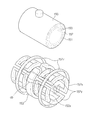
도 4는 자석 어셈블리의 구조와 경사 코일부의 구조를 나타낸 도면이다.
도 5은 경사 코일부를 구성하는 각 경사 코일의 동작과 관련된 펄스 시퀀스를 도시한 도면이다.
도 6a 및 6b는 일 실시예에 따른 스위칭 장치가 신호를 출력하는 여러 가지 방법을 설명하기 위한 도면이다.
도 7은 일 실시예에 따른 스위칭셀의 제어 블록도이다.
도 8은 일 실시예에 따른 1차 스위칭부의 회로도이다.
도 9는 일 실시예에 따른 2차 스위칭부의 회로도이다.
도 10은 일 실시예에 따른 2차 스위칭부의 제 1 모드 선택 시 동작을 설명하기 위한 도면이다..
도 11a 및 11b는 일 실시예에 따른 2차 스위칭부의 제 2 모드 선택 시 동작을 설명하기 위한 도면이다.
도 12는 일 실시예에 따른 스위칭 장치 제어방법의 흐름도이다.1 is a control block diagram of a magnetic resonance imaging apparatus according to an embodiment.
2 is a diagram schematically showing the appearance of a magnetic resonance imaging apparatus.
FIG. 3 is a view showing a space in which a target object is placed by x, y and z axes.
4 is a view showing the structure of the magnet assembly and the structure of the inclined coil part.
5 is a diagram showing a pulse sequence related to the operation of each of the gradient coils constituting the inclined coil part.
6A and 6B are diagrams for explaining various methods of outputting a signal by the switching device according to one embodiment.
7 is a control block diagram of a switching cell according to an embodiment.
8 is a circuit diagram of a primary switching unit according to an embodiment.
9 is a circuit diagram of a secondary switching unit according to an embodiment.
10 is a view for explaining the operation of selecting the first mode of the secondary switching unit according to the embodiment.
FIGS. 11A and 11B are views for explaining the operation of selecting the second mode of the secondary switching unit according to the embodiment.
12 is a flowchart of a switching device control method according to an embodiment.
이하에서는 첨부한 도면을 참조하여 개시된 발명의 일 실시예에 대하여 상세하게 설명한다. 첨부한 도면에서 제시된 동일한 참조번호 또는 부호는 실질적으로 동일한 기능을 수행하는 부품 또는 구성요소를 나타낼 수 있다.Hereinafter, an embodiment of the present invention will be described in detail with reference to the accompanying drawings. Like reference numbers or designations in the accompanying drawings may denote parts or components performing substantially the same function.
도 1은 일 실시예에 따른 자기공명영상장치의 제어 블록도이다. 이하, 도 1을 참조하여 자기공명영상장치의 동작을 개괄적으로 설명하도록 한다. 특히, RF 수신 코일이 자석 어셈블리로부터 분리된 경우를 전제로 설명한다. 1 is a control block diagram of a magnetic resonance imaging apparatus according to an embodiment. Hereinafter, the operation of the MRI apparatus will be described with reference to FIG. In particular, the case where the RF receiving coil is separated from the magnet assembly will be described on the assumption.
도 1을 참조하면, 개시된 발명의 일 실시예에 따른 자기공명영상장치는 자기장을 형성하고 원자핵에 대한 공명 현상을 발생시키는 자석 어셈블리(150)와, 자석 어셈블리(150)의 동작을 제어하는 제어부(120), 원자핵으로부터 발생되는 에코신호 즉, 자기공명신호를 기초로 자기 공명 영상을 생성하는 영상처리부(160) 를 포함한다. 또한, 자기공명영상장치는 자석 어셈블리에 의해 발생한 자기공명신호를 수신하여 영상처리부로 전달하는 RF 수신 코일(170); 및 RF 수신 코일에서 수신한 자기공명신호가 영상처리부로 진행하는 경로를 설정하는 스위칭 장치(200); 를 더 포함한다.Referring to FIG. 1, a magnetic resonance imaging apparatus according to an embodiment of the present invention includes a
자석 어셈블리(150)는 내부 공간에 정자장(Static field)을 형성하는 정자장 코일부(151), 정자장에 경사(gradient)를 발생시켜 경사자장(gradient field)을 형성하는 경사 코일부(152) 및 RF 펄스를 인가하는 RF 송신 코일(153)을 포함한다. 즉, 자석 어셈블리(150)의 내부 공간에 대상체가 위치하면 대상체에 정자장, 경사자장 및 RF 펄스가 인가될 수 있다. 인가된 RF 펄스에 의해 대상체를 구성하는 원자핵이 여기되고, 그로부터 에코 신호가 발생된다. The
RF 수신 코일(170)은 여기된 원자핵이 방출하는 RF 신호 즉, 자기공명신호를 수신할 수 있다. RF 수신 코일(170)은 인체에 부착하여 사용하는 경우가 많아 머리 코일, 목 코일, 허리 코일 등 인체의 부위별 형상에 따라 만드는 것이 일반적이다. The
자석 어셈블리(150)로부터 분리 가능한 RF 수신 코일(170)의 예로 대상체 일부에서 여기된 자기 공명 신호를 받아들이는 표면 코일(surface coil)이 있다. 표면 코일은 체적 코일(volume coil)에 비해 상대적으로 크기가 작고 2차원 면 형태를 취하고 있기 때문에, 인접한 부위에 대하여 월등히 높은 신호 대 잡음비(signal to noise ratio)를 갖는다. An example of an
또한 RF 수신 코일(170)의 다른 예로, 표면 코일 여러 개를 1차원 또는 2차원으로 공간 배열하여 수신 영역을 넓히는 배열형 코일(array coil)이 있다. 배열형 코일은 촬영 부위에 따라 그 배열 형상이 달라지며, 머리용, 두경부용, 흉부용, 척추용, 복부용, 다리용 등으로 분류된다. 배열형 코일을 이루는 각 표면 코일의 상대적인 위치가 다르므로 각 표면 코일이 수신하는 신호의 위상도 차이가 난다. 따라서 각 표면 코일이 수신하는 신호를 합성하여 영상을 재구성할 때, 표면 코일의 수신 위상(receive phase)을 고려함으로써 신호 대 잡음비가 높은 영상을 획득할 수 있다. As another example of the
제어부(120)는 정자장 코일부(151)가 형성하는 정자장의 세기 및 방향을 제어하는 정자장 제어부(121), 펄스 시퀀스를 설계하여 그에 따라 경사 코일부(152) 및 RF 송신 코일(153)을 제어하는 펄스 시퀀스 제어부(122)를 포함한다. The
자기공명영상장치(100)는 경사 코일부(152)에 경사 신호를 인가하는 경사 인가부(130) 및 RF 송신 코일(153)에 RF 신호를 인가하는 RF 인가부(140)를 구비하여 펄스 시퀀스 제어부(122)가 경사 인가부(130) 및 RF 인가부(140)를 제어함으로써 자석 어셈블리(150) 내부 공간에 형성되는 경사자장 및 원자핵에 가해지는 RF를 조절하도록 할 수 있다.The magnetic resonance imaging apparatus 100 includes an
영상처리부(160)는 스핀 에코 신호 즉, 원자핵으로부터 발생되는 자기공명신호에 관한 데이터를 수신하고, 이를 처리하여 자기 공명 영상을 생성하는 데이터 수집부(161), 데이터 수집부(161)에서 수신한 데이터들을 저장하는 데이터 저장부(162), 저장된 데이터들을 처리하여 자기공명영상을 생성하는 데이터 처리부(163)를 포함한다. The
데이터 수집부(161)는 RF 수신 코일(170)이 수신한 자기 공명 신호를 증폭하는 전치 증폭기(preamplifier), 전치 증폭기로부터의 자기 공명 신호를 전송받아 위상 검출하는 위상 검출기, 위상 검출에 의해 획득된 아날로그 신호를 디지털 신호로 변환하는 A/D 컨버터를 포함할 수 있다. 그리고 데이터 수집부(161)는 디지털 변환된 자기 공명 신호를 데이터 저장부(162)로 전송한다. The
데이터 저장부(162)에는 2차원 푸리에(Fourier) 공간을 구성하는 데이터 공간이 형성되며 스캔 완료된 전체 데이터의 저장이 완료되면 데이터 처리부(163)는 2차원 푸리에 공간 내의 데이터를 2차원 역 푸리에 변환하여 대상체(ob)에 대한 영상을 재구성한다. 재구성된 영상은 디스플레이(112)에 표시될 수 있다.A data space constituting a two-dimensional Fourier space is formed in the
또한, 자기공명영상장치(100)는 사용자 조작부(110)를 구비하여 사용자로부터 자기공명영상장치(100)의 전반적인 동작에 관한 제어 명령을 입력받을 수 있고, 특히 사용자로부터 스캔 시퀀스에 관한 명령을 수신하여 이에 따라 펄스 시퀀스를 생성할 수 있다. The magnetic resonance imaging apparatus 100 may also include a
사용자 조작부(110)는 사용자가 시스템을 조작할 수 있도록 마련되는 조작 콘솔(111)과, 제어 상태를 표시하고 영상처리부(160)에서 생성된 영상을 표시하여 사용자로 하여금 대상체의 건강상태를 진단할 수 있도록 하는 디스플레이(112)를 포함할 수 있다.The
도 2는 자기공명영상장치의 외관을 개략적으로 나타낸 도면이고, 도 3은 대상체가 놓여 있는 공간을 x, y, z 축으로 구분한 도면이며, 도 4는 자석 어셈블리의 구조와 경사 코일부의 구조를 나타낸 도면이다.FIG. 2 is a view schematically showing the appearance of a magnetic resonance imaging apparatus, FIG. 3 is a view in which a space in which a subject is placed is divided into x, y and z axes, FIG. 4 is a view showing a structure of a magnet assembly, Fig.
이하 앞서 설명한 도 1을 참조하여 개시된 발명의 일 실시예에 따른 자기공명영상장치(100)의 구체적인 동작에 대해 설명하도록 한다.Hereinafter, a specific operation of the MRI apparatus 100 according to an embodiment of the present invention will be described with reference to FIG.
도 2를 참조하면, 자석 어셈블리(150)는 내부 공간이 비어 있는 원통형의 형상을 하며 갠트리(gantry) 또는 보어(bore)라고도 한다. 그리고, 그 내부 공간은 캐비티(cavity)라고 하며, 환자 테이블(210)은 그 위에 누워 있는 대상체(ob)를 캐비티로 이송시켜 자기 공명 신호를 얻을 수 있도록 한다.Referring to FIG. 2, the
자석 어셈블리(150)는 정자장 코일부(151), 경사 코일부(152), 및 RF 송신 코일(153)을 포함한다.The
정자장 코일부(151)는 캐비티의 둘레를 코일이 감고 있는 형태로 할 수 있고 정자장 코일부(151)에 전류가 인가되면 자석 어셈블리(150) 내부 공간 즉, 캐비티에 정자장이 형성된다.When the current is applied to the part of the static
정자장의 방향은 일반적으로 자석 어셈블리(150)의 동축과 평행하다. The orientation of the sperm field is generally parallel to the coaxial axis of the
캐비티에 정자장이 형성되면 대상체(ob)를 구성하는 원자 특히, 수소 원자의 원자핵은 정자장의 방향으로 정렬되며, 정자장의 방향을 중심으로 세차운동(precession)을 한다. 원자핵의 세차속도는 세차주파수로 나타낼 수 있으며 이를 라모르(Larmor) 주파수라 부르고 아래의 [수학식 1]으로 표현할 수 있다.When a cavity is formed in the cavity, the atom constituting the object (ob), especially the atom of the hydrogen atom, is aligned in the direction of the sperm field and carries out a precession around the direction of the sperm field. The carburizing speed of the nucleus can be expressed by the carburizing frequency, which is called the Larmor frequency and can be expressed by the following equation (1).
[수학식 1][Equation 1]
ω=γB0? =? B0
여기서, ω는 라모르 주파수이고 γ는 비례상수이며 B0는 외부 자기장의 세기이다. 비례상수는 원자핵의 종류마다 달라지며 외부 자기장의 세기의 단위는 테슬라(T) 또는 가우스(G)이고 세차주파수의 단위는 Hz이다. Here, ω is the ramoh frequency, γ is the proportional constant, and B0 is the intensity of the external magnetic field. The proportional constant varies for each kind of atomic nucleus. The unit of intensity of the external magnetic field is Tesla (T) or Gauss (G), and the unit of the car wash frequency is Hz.
예를 들어, 수소 양성자는 1T의 외부 자기장 속에서 42.58MHZ의 세차주파수를 가지며, 인간의 몸을 구성하는 원자 중 가장 큰 비율을 차지하는 것이 수소이므로 자기공명영상장치에서는 주로 수소 양성자의 세차운동을 이용하여 자기 공명 신호를 얻는다.For example, a hydrogen proton has a car wash frequency of 42.58 MHZ in an external magnetic field of 1 T, and since the hydrogen atom that occupies the largest proportion of the atoms constituting the human body is hydrogen, To obtain a magnetic resonance signal.
경사 코일부(152)는 캐비티에 형성된 정자장에 경사(gradient)를 발생시켜 경사자장(gradient magnetic field)를 형성한다. The
도 3에 도시된 바와 같이, 대상체(ob)의 머리부터 발까지의 상하방향과 평행하는 축, 즉 정자장의 방향과 평행하는 축을 z축으로, 대상체(ob)의 좌우방향과 평행하는 축을 x축으로, 공간에서의 상하방향과 평행하는 축을 y축으로 결정할 수 있다.3, an axis parallel to the vertical direction from the head to the foot of the object ob, that is, an axis parallel to the direction of the sperm field is defined as a z-axis, and an axis parallel to the horizontal direction of the object ob is defined as x- , And an axis parallel to the vertical direction in the space can be determined as the y-axis.
자기 공명 신호에 대한 3차원의 공간적인 정보를 얻기 위해서는 x, y, z 축 모두에 대한 경사자장이 요구된다. 이에 경사 코일부(152)는 세 쌍의 경사 코일을 포함한다.In order to obtain three-dimensional spatial information on the magnetic resonance signal, a gradient magnetic field for both the x, y, and z axes is required. The
도 4에 도시된 것처럼 z축 경사 코일(152z)은 일반적으로 한 쌍의 링 타입의 코일로 구성되고, y축 경사 코일(152y)은 대상체(ob)의 위아래에 위치한다. x축 경사 코일(152x)은 대상체(ob)의 좌우측에 위치한다.As shown in Fig. 4, the z-axis tapered
도 5은 경사 코일부를 구성하는 각 경사 코일의 동작과 관련된 펄스 시퀀스를 도시한 도면이다.5 is a diagram showing a pulse sequence related to the operation of each of the gradient coils constituting the inclined coil part.
반대극성을 가진 직류전류가 두 개의 z축 경사 코일(152z) 각각에서 반대 방향으로 흐르게 되면 z축 방향으로 자장의 변화가 발생하여 경사자장이 형성된다.When a DC current having the opposite polarity flows in the opposite direction in each of the two z-axis gradient coils 152z, a change in the magnetic field occurs in the z-axis direction to form a gradient magnetic field.
z축 경사 코일(152z)에 일정 시간 동안 전류를 흘려 주어 경사자장이 형성되면, 공명 주파수는 경사자장의 크기에 따라 크거나 작게 변화된다. 그리고, 특정 위치에 해당하는 고주파 신호를 RF 송신 코일(153)을 통해 인가하면 그 특정 위치에 대응되는 단면의 양성자 만이 공명을 일으킨다. 따라서, z축 경사 코일(154)은 슬라이스 선택에 사용된다. 그리고, z축 방향으로 형성되는 경사자장의 기울기가 클수록 얇은 두께의 슬라이스를 선택할 수 있다.When an electric current is supplied to the z-axis tilted
z축 경사 코일(152z)에 의해 형성된 경사자장을 통해 슬라이스가 선택되면, 슬라이스를 구성하는 스핀들은 모두 동일한 주파수 및 동일한 위상을 가지므로 각 스핀을 구별할 수 없다.When the slice is selected through the inclined magnetic field formed by the z-axis tilted
이 때, y축 경사 코일(152y)에 의해 y축 방향으로 경사자장이 형성되면, 경사자장은 슬라이스의 행(row)들이 서로 다른 위상을 갖도록 위상 시프트를 일으킨다. At this time, if a gradient magnetic field is formed in the y-axis direction by the y-
즉, y축 경사자장이 형성되면 큰 경사자장이 걸린 행의 스핀들은 높은 주파수로 위상이 변하고 작은 경사자장이 걸린 행의 스핀들은 보다 낮은 주파수로 위상이 변한다. y축 경사자장이 사라지면 선택된 슬라이스의 각 행들은 위상 시프트가 일어나 서로 다른 위상을 갖게 되고, 이로 인해 행들을 구별할 수 있다. 이와 같이 y축 경사 코일(152y)에 의해 생긴 경사자장은 위상 부호화(phase encoding)에 사용된다. That is, when a y-axis oblique magnetic field is formed, the spindle of a row with a large oblique magnetic field changes its phase at a high frequency and the spindle of a row with a small oblique magnetic field changes its phase to a lower frequency. When the y-axis oblique magnetic field disappears, each row of the selected slice has a phase shift and has a different phase, thereby distinguishing the rows. Thus, the oblique magnetic field generated by the y-
z축 경사 코일(152z)에 의해 형성된 경사자장을 통해 슬라이스가 선택되고, y축 경사 코일(152y)에 의해 형성된 경사자장을 통해 선택된 슬라이스를 구성하는 행들을 서로 다른 위상으로 구별한다. 그러나 행을 구성하는 각 스핀들은 모두 동일한 주파수 및 동일한 위상을 가지므로 구별할 수 없다.the slice is selected through the inclined magnetic field formed by the z-
이때 x축 경사 코일(152x)에 의해 x축 방향으로 경사자장이 형성되면, x축 경사자장은 각 행을 구성하는 스핀들이 서로 다른 주파수를 갖도록 하여 각각의 스핀을 구별하도록 해준다. 이와 같이 x축 경사 코일(152x)에 의해 생긴 경사자장은 주파수 부호화(frequency encoding)에 사용된다.At this time, if a gradient magnetic field is formed in the x-axis direction by the
전술한 것처럼, z, y, x축 경사 코일에 의해 형성되는 경사자장은 슬라이스 선택, 위상 부호화, 주파수 부호화를 통해 각 스핀들의 공간 위치를 부호화(spatial encoding)한다.As described above, the oblique magnetic field formed by the z, y, and x-axis gradient coils encodes the spatial position of each spindle through slice selection, phase encoding, and frequency encoding.
경사 코일부(152)는 경사 인가부(130)와 접속되어 있고, 경사 인가부(130)는 펄스 시퀀스 제어부(122)로부터 전송받은 제어신호에 따라 경사 코일부(152)에 전류 펄스를 인가하여 경사자장을 발생시킨다. 따라서, 경사 인가부(130)는 경사 전원이라고도 하며, 경사 코일부(152)를 구성하는 세 개의 경사 코일(152z, 152y, 152x)에 대응하여 세 개의 구동회로를 구비할 수 있다. The tilting
상술한 바와 같이 외부 자기장에 의해 정렬된 원자핵들은 Larmor 주파수로 세차운동을 하며 여러 개의 원자핵의 자화(magnetization) 벡터합을 하나의 평균자화(net magnetization) M으로 나타낼 수 있다.As described above, the atomic nuclei aligned by the external magnetic field are carburized at the Larmor frequency, and the magnetization vector sum of several nuclei can be represented as a single net magnetization M.
평균자화의 z축 성분은 측정이 불가능하고, Mxy만이 검출될 수 있다. 따라서 자기 공명 신호를 얻기 위해서는 원자핵을 여기(excitation)시켜 평균자화가 XY 평면 위에 존재하게 해야 한다. 원자핵의 여기를 위해 원자핵의 Larmor 주파수로 tune된 RF 펄스를 정자장에 인가해야 한다.The z-axis component of the average magnetization is not measurable, and only M xy can be detected. Therefore, in order to obtain a magnetic resonance signal, the nucleus must be excited so that the mean magnetization lies on the XY plane. For excitation of the nucleus, RF pulses tuned to the Larmor frequency of the nucleus must be applied to the sperm field.
RF 송신 코일(153)은 RF 인가부(140)와 접속되어 있고, RF 인가부(140)는 펄스 시퀀스 제어부(122)로부터 전송받은 제어신호에 따라 RF 송신 코일(153)에 고주파 신호를 인가하여 RF 송신 코일(153)로 하여금 자석 어셈블리(150) 내부에 RF 펄스를 송신하게 한다. The
RF 인가부(140)는 고주파 신호를 펄스형 신호로 변조하는 변조 회로 및 펄스형 신호를 증폭하는 RF 전력 증폭기를 포함할 수 있다.The
또한, RF 수신 코일(170)은 원자핵으로부터 발생되는 RF 신호, 즉 자기공명신호를 수신할 수 있다. RF 수신 코일(170)은 스위칭 장치(200)를 통해 자기공명신호를 영상처리부(160)로 전송하고, 영상처리부(160)는 이를 처리하여 자기공명영상을 생성할 수 있다. 구체적으로, 영상처리부(160)는 RF 수신 코일로부터 자기공명신호를 수집하여 처리하는 데이터 수집부(161), 데이터 수집부(161)에서 수신한 데이터들을 이용하여 자기공명영상을 생성하는 데이터 처리부를 포함한다. In addition, the
데이터 수집부(161)는 RF 수신 코일(170)이 수신한 자기공명신호를 증폭하는 전치 증폭기(preamplier), 전치 증폭기로부터의 자기 공명 신호를 전송받아 위상 검출하는 위상 검출기, 위상 검출에 의해 획득된 아날로그 신호를 디지털 신호로 변환하는 A/D 컨버터를 포함한다. 그리고 데이터 수집부(161)는 디지털 변환된 자기 공명 신호를 데이터 저장부(162)로 전송한다.The
이와는 달리, RF 수신 코일(170)이 수신한 자기 공명 신호를 증폭하는 증폭 장치를 포함하고, 데이터 수집부는 전치 증폭기를 포함하지 않을 수도 있다. Alternatively, the
데이터 저장부(162)에는 2차원 푸리에 공간을 구성하는 데이터 공간이 형성되며 스캔 완료된 전체 데이터의 저장이 완료되면 데이터 처리부(163)는 2차원 푸리에 공간 내의 데이터를 2차원 역 푸리에 변환하여 대상체(ob)에 대한 영상을 재구성한다. 재구성된 영상은 디스플레이(112)에 표시된다.The
원자핵으로부터 자기공명신호를 얻기 위해 주로 사용되는 방법으로 스핀 에코 펄스 시퀀스가 있다. RF 송신 코일(153)에서 RF 펄스를 인가 할 때, 첫 번째 RF 펄스 인가 후 적당한 시간 간격 △t를 두고 RF 펄스를 한번 더 송신하면, 그로부터 △t시간이 경과하였을 때 원자핵들에 강한 횡자화가 나타나며 이로부터 자기 공명 신호를 얻을 수 있다. 이를 스핀 에코 펄스 시퀀스라 하고, 첫 번째 RF 펄스 인가후 자기 공명 신호가 발생할 때까지 걸리는 시간을 TE(Time Echo)라 한다. There is a spin-echo pulse sequence that is commonly used to obtain magnetic resonance signals from an atomic nucleus. When an RF pulse is applied in the
양성자가 얼마나 플립(flip)되었는지 여부는 플립되기 전에 위치하던 축으로부터 이동한 각으로 나타낼 수 있으며, 플립 정도에 따라 90도 RF 펄스, 180도 RF 펄스 등으로 나타낸다. Whether or not the proton has been flipped can be represented by the angle from the axis that was positioned before the flip, and it can be expressed by 90 degree RF pulse or 180 degree RF pulse depending on the degree of flip.
한편, RF 수신 코일은 영상을 얻고자 하는 대상체(예를 들어, 인체의 특정 부위)에 따라 그 종류가 달라진다. 예를 들어, RF 수신 코일은 Head 코일, Spine 코일, Shoulder 코일, Breast 코일, Torso 코일, Knee 코일, PV 코일 또는 Foot-Ankle 코일 등을 포함할 수 있다.On the other hand, the type of the RF receiving coil varies depending on a target object (for example, a specific region of the human body) from which an image is to be obtained. For example, the RF receive coil may include a Head coil, a Spine coil, a Shoulder coil, a Breast coil, a Torso coil, a Knee coil, a PV coil, or a Foot-Ankle coil.
스위칭 장치(200)는 상술한 여러 종류의 RF 수신 코일과 접속 가능한 복수의 입력채널(310)을 통해 RF 수신 코일이 수신한 자기공명신호, 즉 RF 신호를 수신할 수 있다. 구체적으로, 스위칭 장치(200)의 복수의 입력채널(310)는 여러 종류의 RF 수신 코일을 구성하는 복수의 코일 각각에 할당될 수 있다. 그 결과, 스위칭 장치(200)의 각각의 입력채널(310)는 여러 종류의 RF 수신 코일을 구성하는 복수의 코일 각각에서 수신한 RF 신호를 입력받을 수 있다.The
스위칭 장치(200)는 이렇게 입력 받은 RF 신호 일부 또는 전부를 출력하는 복수의 출력채널(320)을 포함할 수 있고, 복수의 출력채널(320)는 영상처리부(160)에 접속되어 RF 신호를 출력함으로써 영상처리부(160)로 전송할 수 있다.The
이 때, 스위칭 장치(200)는 각각의 입력채널(310)에 입력된 RF 신호 중 자기공명영상을 생성하고자 하는 대상체(ob)로부터 수신한 RF 신호만을 출력하도록 복수의 입력채널(310)과 복수의 출력채널(320) 간의 연결관계를 스위칭할 수 있다. 특히, 입력채널(310)과 출력채널(320)의 수가 상이한 경우, 스위칭 장치(200)는 입력채널(310)과 출력채널(320)의 연결관계를 스위칭함으로써 수신한 RF 신호를 선별적으로 영상처리부(160)로 전송할 수 있다.The
이를 위해, 통상적인 스위칭 장치(200)는 각각의 입력채널(310)과 각각의 출력채널(320)을 연결하는 복수의 스위치를 마련할 수 있다. 이 경우, M 개의 입력채널(310)과 N개의 출력채널(320)을 가지는 스위칭 장치(200)는 MXN개의 스위치를 구비할 필요가 있다. 만약, 입력채널(310) 및 출력채널(320)의 수가 증가함에 따라 필요한 스위치의 기하급수적으로 증가하므로, 스위칭 장치(200) 회로의 대형화 문제가 야기될 수 있다. 또한, 이는 제조원가의 증가를 가져올 수 있다. 뿐만 아니라, 많은 수의 스위치를 개별적으로 제어하는 데서 오는 회로 구성의 난이도 증가와, 이로부터 유발되는 신호의 간섭문제도 발생할 수 있다.To this end, a
또한, 스위칭 장치(200)의 N개의 출력채널(320)은 N개의 입력채널을 가지는 영상처리부(160)와 접속될 수도 있고, N/2 개의 입력채널을 가지는 영상처리부(160)와 접속될 수도 있다. 이 경우, 스위칭 장치(200)는 출력채널(320)에 접속되는 영상처리부(160)의 입력채널의 수에 대응하여 RF 신호를 출력하는 출력채널(320)의 수를 달리할 필요가 있다.The
따라서, 적은 수의 스위치를 이용하여 회로 구성을 간소화 하면서도, 동일한 신호의 출력이 가능하고, 선택에 따라 RF 신호를 출력하는 출력채널 그룹을 달리하는 스위칭 장치(200) 및 이를 포함하는 자기공명영상장치(100)가 요구된다.Therefore, it is possible to provide a
이하에서는 상술한 문제를 해결하기 위한 스위칭 장치(200)에 대하여 상세히 설명한다.Hereinafter, the
도 6a 및 6b는 일 실시예에 따른 스위칭 장치가 신호를 출력하는 여러 가지 방법을 설명하기 위한 도면이다. 도 6a및 6b의 스위칭 장치(200)는 RF 수신 코일(170)을 구성하는 복수의 코일 각각이 접속 가능한 M개의 입력채널(310); 및 영상처리부(160)와 접속되는 N개의 출력채널(320); 를 포함하는 경우를 예시한다.6A and 6B are diagrams for explaining various methods of outputting a signal by the switching device according to one embodiment. The
도 6a를 참조하면, MXN의 스위칭 장치(200)는 8X4의 스위칭셀(300)로 분할될 수 있다. 즉, M개의 입력채널(310)과 N개의 출력채널(320)을 가지는 스위칭 장치(200)는 여덟 개의 입력채널(310)과 네 개의 출력채널(320)로 구성되는 복수의 스위칭셀(300)로 구성될 수 있다. 복수의 스위칭셀(300) 각각은 서로 독립적으로 구성되어, 하나의 스위칭셀(300)이 포함하는 여덟 개의 입력채널(310)과 네 개의 출력채널(320) 간의 연결관계를 제어할 수 있다.Referring to FIG. 6A, the
만약, 스위칭 장치(200)의 N개의 출력채널에 영상처리부(160)의 N개의 입력채널이 접속되면, 스위칭 장치(200)는 N개의 출력채널에서 출력되는 N개의 RF 신호를 영상처리부(160)로 전달할 수 있다. 이를 위해, 각각의 스위칭셀(300)의 네 개의 출력채널은 네 개의 RF 신호를 출력할 수 있다.If the N input channels of the
반면, 스위칭 장치(200)의 N개의 출력채널 중 일부에만 영상처리부(160)의 입력채널이 접속될 수 있다. 예를 들어, 스위칭 장치(200)의 N개의 출력채널 중 N/2개에만 영상처리부(160)의 입력채널 N/2개가 접속될 수 있다. 이 경우, 스위칭 장치(200)는 영상처리부(160)의 입력채널과 접속된 N/2 개의 출력채널을 통해 RF 신호가 출력될 수 있도록, 입력채널과 출력채널의 연결관계를 스위칭할 수 있다.On the other hand, only a part of the N output channels of the
구체적으로, 각각의 스위칭셀(300)의 네 개의 출력채널 중 두 개에서만 RF 신호를 출력하도록, 입력채널과 출력채널의 연결관계를 스위칭 할 수 있다. 그 결과, 도 6b와 같이, 스위칭 장치(200)는 각각의 스위칭셀(300)이 여덟 개의 입력채널과 두 개의 출력채널을 가지는 경우와 동일하게 동작할 수도 있다.Specifically, the connection relationship between the input channel and the output channel can be switched so that only two of the four output channels of each switching
이처럼, 개시된 실시예에 따른 스위칭 장치(200)는 하드웨어의 교체 또는 추가 없이도 RF 신호를 출력하는 출력채널을 가변적으로 제어할 수 있다. 특히, 이와 같은 동작은 스위칭 장치(200)를 구성하는 각각의 스위칭셀(300) 레벨에서 동일하게 이루어지므로, 이하에서는 개시된 실시예에 따른 스위칭 장치(200)를 구성하는 하나의 스위칭셀(300)에 대하여 상세히 설명한다.As described above, the
도 7은 일 실시예에 따른 스위칭셀의 제어 블록도이다.7 is a control block diagram of a switching cell according to an embodiment.
일 실시예에 따른 스위칭셀(300)은, 여덟 개의 입력채널(310) 및 네 개의 출력채널(320); 이들의 연결관계를 스위칭하는 스위칭부(330); 및 스위칭부(330)를 제어하는 스위칭 제어부(900); 를 포함할 수 있다.The switching
스위칭 제어부(900)는 후술할 스위칭부(330)를 구성하는 1차 스위칭부(400) 및 2차 스위칭부(500)를 제어함으로써 입력채널 및 출력채널의 연결관계를 스위칭 할 수 있다. 구체적으로, 스위칭 제어부(900)는 스위칭 장치(200)의 동작 이전에 스위칭부(330)의 모드를 미리 선택할 수 있다. 이에 대하여는 스위칭부(330)의 설명과 함께 상세히 기술한다.The switching
스위칭 제어부(900)는 마이크로 프로세서와 같은 하드웨어로 구현될 수 있으며, 이와는 달리 하드웨어에 의해 구동되는 소프트웨어로 구현되는 것도 가능할 수 있다.The switching
여덟 개의 입력채널(310)은 RF 수신 코일(170)과 접속 가능할 수 있다. 스위칭셀(300)을 구성하는 여덟 개의 입력채널(310) 각각은 동일한 RF 수신 코일(170)에 속하는 각각의 코일과 접속될 수도 있고, 서로 다른 종류의 RF 수신 코일(170)에 속하는 코일과 접속될 수도 있다.Eight
네 개의 출력채널(320)는 영상처리부(160)와 접속 가능할 수 있다. 두 개의 출력채널(320)을 통해 출력되는 RF 신호는 영상처리부(160)에서 자기공명영상으로 변환될 수 있다.The four
이 때, 네 개의 출력채널(320)은 스위칭 장치(200)의 모드에 따라 RF 신호를 출력하는 출력채널을 달리할 수 있다. 구체적으로, 스위칭 장치(200)의 모드에 따라 네 개의 출력채널(320) 전체 또는 네 개의 출력채널 중 두 개에서만 RF 신호를 출력할 수 있다. In this case, the four
이를 위해, 네 개의 출력채널(320) 전체를 제 1 출력채널 그룹으로, 네 개의 출력채널 중 미리 정해진 두 개를 제 2 출력채널 그룹으로 미리 설정할 수 있다. 도 7에서 제 1 출력채널 그룹은 G1으로 나타내고, 제 2 출력채널 그룹은 G2로 나타낸다.To this end, the four
스위칭부(330)는 스위칭 제어부(900)의 제어에 따라, 여덟 개의 입력채널과 네 개의 출력채널 전체, 즉 제 1 출력채널 그룹 G1, 또는 일부, 즉 제 2 출력채널 그룹 G2, 의 연결관계를 스위칭할 수 있다.Under the control of the switching
이를 위해, 스위칭부(330)는 입력채널을 통해 입력되는 RF 신호의 경로를 1차적으로 스위칭하는 1차 스위칭부(400); 및 1차 스위칭부(400)에서 출력된 RF 신호가 최종적으로 출력되는 출력채널을 스위칭하는 2차 스위칭부(500); 를 포함할 수 있다.For this, the
1차 스위칭부(400)는 여덟 개의 입력채널(310)과 연결되는 1차 입력채널(440a, 440b) 및 네 개의 1차 출력채널(450a, 450b)의 연결관계를 스위칭할 수 있다. 이를 위해, 1 차 스위칭부(400)는 여덟 개의 1차 입력채널(440a, 440b) 중 어느 네 개(440a) 및 네 개의 1 차 출력채널(450a, 450b) 중 어느 두 개(450a)의 연결관계를 스위칭하는 제 1 하위 스위칭부(400a); 및 여덟 개의 1 차 입력채널(440a, 440b) 중 나머지 네 개(440b) 및 네 개의 1차 출력채널(450a, 450b) 중 나머지 두 개(450b)의 연결관계를 스위칭하는 제 2 하위 스위칭부(400b); 를 포함할 수 있다.The
도 8은 일 실시예에 따른 1차 스위칭부의 회로도이다. 제 1 하위 스위칭부(400a)와 제 2 하위 스위칭부(400b)는 회로적으로 동일한 구성을 가지므로, 대응되는 구성의 도번을 일치시키고, 양자를 구분하기 위해 a 또는 b를 부가하였다.8 is a circuit diagram of a primary switching unit according to an embodiment. Since the first
도 8에서는 제 1 하위 스위칭부(400a)와 제 2 하위 스위칭부(400b)의 회로도를 모두 도시하고 있으나, 설명의 편의상 제 1 하위 스위칭부(400a)를 기준으로 설명하며, 제 2 하위 스위칭부(400b) 역시 제 1 하위 스위칭부(400a)와 동일하게 동작할 수 있다.Although the circuit diagrams of the first
상술한 바와 같이, 일 실시예에 따른 1차 스위칭부(400)는 제 1 하위 스위칭부(400a)와 제 2 하위 스위칭부(400b)를 포함할 수 있다. As described above, the
제 1 하위 스위칭부(400a)는 여덟 개의 1차 입력채널(440a, 440b) 중 네 개(440a)와 네 개의 1차 출력채널(450a, 450b) 중 두 개(450a)의 연결관계를 스위칭 할 수 있다. 이를 위해, 제 1 하위 스위칭부(400a)는 제 1-1 하위 스위칭부(410a); 제 1-2 하위 스위칭부(420a); 및 제 1-3 하위 스위칭부(430a);를 포함할 수 있다.The first
제 1-1 하위 스위칭부(410a)는 제 1 하위 스위칭부(400a)와 접속된 네 개의 1차 입력채널(440a) 중 두 개(442a, 443a)에서 연장되는 경로의 스위칭이 가능하도록 마련될 수 있다. 예를 들어 제 1 하위 스위칭부(400a)가 1차 입력채널 중 제 2 입력채널(442a) 및 제 3 입력채널(443a)과 접속되면, 제 1-1 하위 스위칭부(410a)는 1차 입력채널 중 제 2 입력채널(442a)과 연결되는 제 1 하위 입력채널(411a), 및 1차 입력채널 중 제 3 입력채널(443a)과 연결되는 제 2 하위 입력채널(412a); 제 1 하위 출력채널(413a), 및 제 2 하위 출력채널(414a); 및 제 1 하위 입력채널(411a)를 제 1 하위 출력채널(413a) 및 제 2 하위 출력채널(414a) 중 어느 하나와 연결하면서, 제 2 하위 입력채널(412a)를 제 1 하위 출력채널(413a) 및 제 2 하위 출력채널(414a) 중 다른 하나와 연결하는 제 1 스위치(415a)(415a); 를 포함할 수 있다. The 1-1 second
도 8을 참조하면, 제 1 스위치(415a)(415a)는 제 1 하위 입력채널(411a)과 제 1 하위 출력채널(413a)을 연결 시, 제 2 하위 입력채널(412a)과 제 2 하위 출력채널(414a)을 연결할 수 있다. 이와는 달리, 제 1 스위치(415a)(415a)는 제 1 하위 입력채널(411a)과 제 2 하위 출력채널(414a)을 연결하면서, 제 2 하위 입력채널(412a)과 제 1 하위 출력채널(413a)을 연결할 수도 있다. Referring to FIG. 8, the
그 결과, 제 1 스위치(415a)(415a)가 제 1 하위 입력채널(411a)-제 1 하위 출력채널(413a) 경로 및 제 2 하위 입력채널(412a)-제 2 하위 출력채널(414a) 경로를 형성하면, 1차 입력채널 중 제 2 입력채널(442a)에서 수신한 RF 신호는 제 1 하위 출력채널(413a)에서 출력될 수 있고, 1차 입력채널 중 제 3 입력채널(443a)에서 수신한 RF 신호는 제 2 하위 출력채널(414a)에서 출력될 수 있다. 또한, 제 1 스위치(415a)(415a)가 제 1 하위 입력채널(411a)-제 2 하위 출력채널(414a) 및 제 2 하위 입력채널(412a)-제 1 하위 출력채널(413a)의 경로를 형성하면, 1차 입력채널 중 제 2 입력채널(442a)에서 수신한 RF 신호는 제 2 하위 출력채널(414a)에서 출력될 수 있고, 1차 입력채널 중 제 3 입력채널(443a)에서 수신한 RF 신호는 제 1 하위 출력채널(413a)에서 출력될 수 있다.As a result, the
이처럼, 제 1-1 하위 스위칭부(410a)는 제 1하위 입력채널(411a), 제 2 하위 입력채널(412a), 제 1 하위 출력채널(413a), 및 제 2 하위 출력채널(414a) 간의 연결관계를 제어함으로써, 1차 입력채널 중 제 2 입력채널(442a)에서 연장되는 경로와 1차 입력채널 중 제 3 입력채널(443a)에서 연장되는 경로를 스위칭 할 수 있다.The first
일 실시예에 따른 제 1-1 하위 스위칭부(410a) 는 DPDT(Double Pole Double Throw)의 형태로 구현될 수 있으나, 반드시 이에 한정되는 것은 아니다.The first-
제 1-2 하위 스위칭부(420a) 는 제 1-1 하위 스위칭부(410a) 가 형성하는 어느 하나의 경로 또는 1차 입력채널 중 제 1 입력채널(441a)를 1차 출력채널 중 제 1 출력채널(451a)과 선택적으로 연결할 수 있다. 또한, 제 1-3 하위 스위칭부(430a) 는 제 1-1 하위 스위칭부(410a)가 형성하는 다른 하나의 경로 또는 1차 입력채널 중 제 4 입력채널(444a)를 1차 출력채널 중 제 2 출력채널(452a)와 선택적으로 연결할 수 있다.The first-second
이를 위해, 제 1-2 하위 스위칭부(420a)는 1차 입력채널 중 제 1 입력채널(441a) 또는 제 1-1 하위 스위칭부(410a)의 제 1 하위 출력채널(413a)를 1차 출력채널 중 제 1 출력채널(451a)와 선택적으로 연결하고, 제 1-3 하위 스위칭부(430a) 는 1차 입력채널 중 제 4 입력채널(444a) 또는 제 1-1 하위 스위칭부(410a) 의 제 2 하위 출력채널(414a)를 1차 출력채널 중 제 2 출력채널(452a)와 선택적으로 연결할 수 있다.To this end, the 1 st to 2 nd
도 8을 참조하면, 제 1-2 하위 스위칭부(420a) 는 1차 입력채널 중 제 1 입력채널(441a)와 연결되는 제 3 하위 입력채널(421a), 및 제 1 하위 출력채널(413a)와 연결되는 제 4 하위 입력채널(422a); 1차 출력채널 중 제 1 출력채널(451a)과 연결되는 제 3 하위 출력채널(423a); 및 제 3 하위 입력채널(421a) 및 제 4 하위 입력채널(422a) 중 어느 하나를 제 3 하위 출력채널(423a)와 연결하는 제 2 스위치(424a); 를 포함할 수 있다. Referring to FIG. 8, the first-second
그 결과, 제 2 스위치(424a)가 제 3 하위 입력채널(421a)와 제 3 하위 출력채널(423a)를 연결하면, 1차 입력채널 중 제 1 입력채널(441a)에서 수신되는 RF 신호는 1차 출력채널 중 제 1 출력채널(451a)를 통해 출력될 수 있다. 이와는 달리, 제 2 스위치(424a)가 제 4 하위 입력채널(422a)와 제 3 하위 출력채널(423a)를 연결하면, 제 2 입력채널(442a) 또는 제 3 입력채널(443a)에서 수신되는 RF 신호가 1차 출력채널 중 제 1 출력채널(451a)를 통해 출력될 수 있다.As a result, when the
이처럼, 제 1-2 하위 스위칭부(420a) 가 제 3 하위 출력채널(423a)을 제 3 하위 출력채널(423a) 또는 제 4 하위 입력채널(422a)와 선택적으로 연결함으로써, 1차 출력채널 중 제 1 출력채널(451a)는 1차 입력채널 중 제 1 입력채널(441a), 1차 입력채널 중 제 2 입력채널(442a), 또는 1차 입력채널 중 제 3 입력채널(443a)를 통해 수신되는 RF 신호를 출력할 수 있다. In this way, the first-second
제 1-2 하위 스위칭부(420a) 와 유사하게, 제 1-3 하위 스위칭부(430a) 는 제 2 하위 출력채널(414a)와 연결되는 제 5 하위 입력채널(431a), 및 1차 입력채널 중 제 4 입력채널(444a)와 연결되는 제 6 하위 입력채널(432a); 1차 출력채널 중 제 2 출력채널(452a)와 연결되는 제 4 하위 출력채널(433a); 및 제 5 하위 입력채널(431a) 및 제 6 하위 입력채널(432a) 중 어느 하나를 제 4 하위 출력채널(433a)와 연결하는 제 3 스위치(434a); 를 포함할 수 있다. Similar to the first-second
그 결과, 제 3 하위 스위치(434a)가 제 5 하위 입력채널(431a)와 제 4 하위 출력채널(433a)를 연결하면, 1차 입력채널 중 제 2 입력채널(442a) 또는 제 3 입력채널(443a)에서 수신되는 RF 신호가 1차 출력채널 중 제 2 출력채널(452a)를 통해 출력될 수 있다. 이와는 달리, 제 3 스위치(434a)가 제 6 하위 입력채널(432a)와 제 4 하위 출력채널(433a)를 연결하면, 1차 입력채널 중 제 4 입력채널(444a)에서 수신되는 RF 신호는 1차 출력채널 중 제 2 출력채널(452a)를 통해 출력될 수 있다. As a result, when the third
이처럼, 제 1-3 하위 스위칭부(430a) 가 제 4 하위 출력채널(433a)를 제 5 하위 입력채널(431a) 또는 제 6 하위 입력채널(432a)와 선택적으로 연결함으로써, 1차 출력채널 중 제 2 출력채널(452a)는 1차 입력채널 중 제 2 입력채널(442a), 1차 입력채널 중 제 3 입력채널(443a), 또는 1차 입력채널 중 제 4 입력채널(444a)를 통해 수신되는 RF 신호를 출력할 수 있다. The first to third
일 실시예에 따른 제 1-2 하위 스위칭부(420a), 및 제 1-3 하위 스위칭부(430a) 는 SPDT(Single Pole Double Throw) 또는 SP2T(Single Pole Two Throw)의 형태로 구현될 수 있으나, 반드시 이에 한정되는 것은 아니다.The first to the first
상술한 실시예에 따른 스위칭셀(300)은 입력채널(310)을 통해 입력되는 4 개의 RF 신호 중 두 개 G2로 구성되는 모든 조합을 출력신호로서 출력할 수 있다. 이는, 일 실시예에 따른 스위칭셀(300)이 입력신호에 대한 원하는 출력신호를 출력할 수 있는 자유도를 가짐을 의미할 수 있다.The switching
도 8에서는 제 1-2 하위 스위칭부(420a) 및 제 1-3 하위 스위칭부(430a) 가 SPDT 또는 SP2T 의 형태로 구현되는 경우를 예시하였다. 그러나, 제 1-2 하위 스위칭부(420a) 및 제 1-3 하위 스위칭부(430a) 는 DPDT의 형태로 구현될 수도 있다.In FIG. 8, the first-second
다시 도 7을 참조하면, 2차 스위칭부(500)는 1차 스위칭부(400)에서 출력된 RF 신호가 최종적으로 출력되는 출력채널(320)을 스위칭할 수 있다. Referring again to FIG. 7, the
이를 위해, 2차 스위칭부(500)는 선택된 모드에 따라 동작하는 모드 선택부; 및 제 2 모드가 선택되면, 제 2 출력채널 그룹 G2과 2차 입력채널(610)의 연결관계를 스위칭하는 제 3 하위 스위칭부(700); 를 포함할 수 있다.For this, the
도 9는 일 실시예에 따른 2차 스위칭부의 회로도이다.9 is a circuit diagram of a secondary switching unit according to an embodiment.
모드 선택부는 제 1 모드 선택 시 2차 입력채널(610)과 2차 출력채널(820)을 연결하도록 동작할 수 있다. 이를 위해, 모드 선택부는 2차 스위칭부(500)의 2차 입력채널(610)로부터의 경로를 형성 또는 차단하는 제 1 모드 선택부(600); 및 2차 스위칭부(500)의 2차 출력채널(820)로의 경로를 형성 또는 차단하는 제 2 모드 선택부(700); 를 포함할 수 있다.The mode selection unit may operate to connect the
제 1 모드 선택부(600)는 네 개의 2차 입력채널(610); 제 5 내지 12 하위 출력채널; 및 두 개의 하위 출력채널 중 어느 하나를 하나의 2 차 입력채널과 연결하는 제 1 모드 선택 스위칭부(330); 를 포함할 수 있다.The
도 9를 참조하면, 네 개의 2 차 입력채널 각각은 1차 스위칭부(400)의 1차 출력채널 네 개(451a, 452a, 451b, 451b)와 각각 연결될 수 있다. 또한, 각각의 2차 입력채널(610)은 제 1 모드 선택 스위칭부(330)와 연결될 수 있다.Referring to FIG. 9, each of the four secondary input channels may be connected to four
제 1 모드 선택 스위칭부(330)는 2차 입력채널(610)과 연결되어 제 5 내지 12 하위 출력채널(620) 중 네 개와 연결되도록 동작할 수 있다. 이를 위해, 제 1 모드 선택 스위칭부(330)는 2차 입력채널(610) 중 제 1 입력채널(611)과 제 5 하위 출력채널(621) 또는 제 6 하위 출력채널(622)을 연결하는 제 1 모드 선택 스위치(631); 2차 입력채널(610) 중 제 2 입력채널(612)과 제 7 하위 출력채널(623) 또는 제 8 하위 출력채널(624)을 연결하는 제 2 모드 선택 스위치(632); 2차 입력채널(610) 중 제 3 입력채널(613)과 제 9 하위 출력채널(625) 또는 제 10 하위 출력채널(626)을 연결하는 제 3 모드 선택 스위치(633); 및 2차 입력채널(610) 중 제 4 입력채널(614)과 제 11 하위 출력채널(627) 또는 제 12 하위 출력채널(628)을 연결하는 제 4 모드 선택 스위치(634); 를 포함할 수 있다.The first mode
제 1 내지 4 모드 선택 스위치(630)는 SPDT(Single Pole Double Throw) 또는 SP2T(Single Pole Two Throw)의 형태로 구현될 수 있으나, 반드시 이에 한정되는 것은 아니다.The first to fourth mode selection switches 630 may be implemented in the form of a single pole double throw (SPDT) or a single pole two throw (SP2T), but are not limited thereto.
제 2 모드 선택부(700)는 여덟 개의 제 17 내지 24 하위 입력채널; 2차 출력채널(820); 및 두 개의 하위 입력채널 중 어느 하나를 하나의 2차 출력채널(820)과 연결하는 제 2 모드 선택 스위칭부(830); 를 포함할 수 있다.The second
도 9를 참조하면, 네 개의 2차 출력채널(820) 각각은 2차 스위칭부(500)의 2차 출력채널(820) 네 개와 각각 연결될 수 있다. 또한, 각각의 2차 출력채널(820)은 제 2 모드 선택 스위칭부(830)와 연결될 수 있다.Referring to FIG. 9, each of the four
제 2 모드 선택 스위칭부(830)는 2차 출력채널(820)과 연결되어 제 17 내지 24 하위 입력채널 중 네 개와 연결되도록 동작할 수 있다. 이를 위해, 제 2 모드 선택 스위칭부(830)는 2차 출력채널(820) 중 제 1 출력채널(821)과 제 17 하위 입력채널(811) 또는 제 18 하위 입력채널(812)을 연결하는 제 5 모드 선택 스위치(831); 2차 출력채널(820) 중 제 2 출력채널(822)과 제 19 하위 입력채널(813) 또는 제 20 하위 입력채널(814)을 연결하는 제 6 모드 선택 스위치; 2차 출력채널(820) 중 제 3 출력채널(823)과 제 21 하위 입력채널(815) 또는 제 22 하위 입력채널(816)을 연결하는 제 7 모드 선택 스위치(833); 및 2차 출력채널(820) 중 제 4 출력채널(824)과 제 23 하위 입력채널(817) 또는 제 24 하위 입력채널(818)을 연결하는 제 8 모드 선택 스위치(833); 를 포함할 수 있다.The second mode
제 5 내지 8 모드 선택 스위치(830)는 SPDT(Single Pole Double Throw) 또는 SP2T(Single Pole Two Throw)의 형태로 구현될 수 있으나, 반드시 이에 한정되는 것은 아니다.The fifth to eighth mode selection switches 830 may be implemented in the form of a single pole double throw (SPDT) or a single pole two throw (SP2T), but are not limited thereto.
제 3 하위 스위칭부(700)는 제 2 모드가 선택되면, 제 2 출력채널 그룹 G2과 2차 입력채널(610)의 연결관계를 스위칭할 수 있다. 제 3 하위 스위칭부(700)는 제 1 하위 스위칭부(400a) 및 제 2 하위 스위칭부(400b)와 구성 및 동작이 동일하다. 따라서, 이하에서는 2차 스위칭부(500)에 대한 제 3 하위 스위칭부(700)의 연결관계에 대하여만 설명한다.The third
제 3 하위 스위칭부(700)는 제 7 내지 10 하위 입력채널과 제 17 및 18 하위 출력채널의 연결관계를 스위칭할 수 있다.The third
제 3 하위 스위칭부(700)의 제 7 내지 10 하위 입력채널은 각각 제 1 모드 선택부(600)의 제 6 하위 출력채널(622), 제 8 하위 출력채널(624), 제 10 하위 출력채널(626), 및 제 12 하위 출력채널(628)과 연결될 수 있다. The seventh to tenth lower input channels of the third
또한, 제 8 하위 입력채널(712) 및 제 9 하위 입력채널(713) 각각은 제 3-1 하위 스위칭부(730)의 제 11 하위 입력채널(731) 및 제 12 하위 입력채널(732)과 연결될 수 있다. 하위 스위칭부(330)는 제 11 하위 입력채널(731)을 제 13 하위 출력채널(734)과 연결 시, 제 12 하위 입력채널(732)을 제 14 하위 출력채널(735)과 연결할 수 있다. 이와는 반대로, 하위 스위칭부(330)는 제 11 하위 입력채널(731)을 제 14 하위 출력채널(735)과 연결 시, 제 12 하위 입력채널(732)을 제 13 하위 출력채널(734)과 연결할 수도 있다. 이를 위해, 하위 스위칭부(330)는 제 4 스위치(733)를 포함할 수 있으며, 이는 도 8에서의 제 1 스위치(415a)와 동일할 수 있다.Each of the eighth
또한, 제 7 하위 입력채널(711) 및 제 13 하위 출력채널(734) 각각은 제 3-2 하위 스위칭부(740)의 제 13 하위 입력채널(741) 및 제 14 하위 입력채널(742)과 연결되고, 제 14 하위 출력채널(735) 및 제 10 하위 입력채널(714)은 제 3-3 하위 스위칭부(750)의 제 15 하위 입력채널(751) 및 제 16 하위 입력채널(752)과 연결될 수 있다.Each of the seventh
제 3-2 하위 스위칭부(740)는 제 17 하위 출력채널(721)과 연결되는 제 15 하위 출력채널(744)을 제 13 하위 입력채널(741) 또는 제 14 하위 입력채널(742)과 연결하는 제 5 스위치(743)를 포함할 수 있으며, 이는 도 8에서의 제 2 스위치(424a)와 동일할 수 있다.The 3-2
제 3-3 하위 스위칭부(750)는 제 18 하위 출력채널(722)과 연결되는 제 16 하위 출력채널(754)을 제 15 하위 입력채널(751) 또는 제 16 하위 입력채널(752)과 연결하는 제 6 스위치(753)를 포함할 수 있으며, 이는 도 8에서의 제 3 스위치(434a)와 동일할 수 있다.The third 3-3
지금까지는 2차 스위칭부(500)의 회로 구성에 대하여 설명하였다. 이하에서는 2차 스위칭부(500)의 구체적인 동작을 설명한다.The circuit configuration of the
상술한 바와 같이, 스위칭 제어부(900)는 스위칭 장치(200)의 동작 이전에 스위칭부(330)의 모드를 미리 선택할 수 있다. 이 때, 스위칭부(330)의 모드는 사용자의 입력 또는 스위칭 제어부(900) 내부의 연산에 의해 미리 선택될 수 있다.As described above, the switching
스위칭부(330)의 모드는 제 1 모드와 제 2 모드로 구분될 수 있다. 여기서, 제 1 모드는 스위칭셀(300)의 네 개의 출력채널 전체, 즉 제 1 출력채널 그룹 G1을 통해 RF 신호를 출력하는 모드를 의미한다. 또한, 제 2 모드는 스위칭셀(300)의 네 개의 출력채널 중 두 개, 즉 제 2 출력채널 그룹 G2에서만 RF 신호를 출력하는 모드를 의미한다.The mode of the
모드가 선택되면, 스위칭 제어부(900)는 선택된 모드에 대응되도록 2차 스위칭부(500)를 제어할 수 있다.Mode is selected, the switching
도 10은 일 실시예에 따른 2차 스위칭부의 제 1 모드 선택 시 동작을 설명하기 위한 도면이다.FIG. 10 is a view for explaining the operation of selecting the first mode of the secondary switching unit according to an embodiment.
제 1 모드 선택 시, 모드 선택부는 2차 입력채널(610) 각각이 2차 출력채널(820) 각각과 순차적으로 연결되도록 경로를 형성할 수 있다. 즉, 모드 선택부는 2차 입력채널(610) 중 제 1 입력채널(611)이 2차 출력채널(820) 중 제 1 출력채널(821)과 연결되고, 2차 입력채널(610) 중 제 2 입력채널(612)이 2차 출력채널(820) 중 제 2 출력채널(822)과 연결되고, 2차 입력채널(610) 중 제 3 입력채널(613)이 2차 출력채널(820) 중 제 3 출력채널(823)과 연결되고, 2차 입력채널(610) 중 제 4 입력채널(614)이 2차 출력채널(820) 중 제 4 출력채널(824)과 연결되는 경로를 형성할 수 있다.When the first mode is selected, the mode selection unit may form a path such that each of the
이를 위해, 제 1 모드 선택 스위치(631)는 2차 입력채널(610) 중 제 1 입력채널(611)과 제 5 하위 출력채널(621)을 연결하고, 제 5 모드 선택 스위치(831)는 2차 출력채널(820) 중 제 1 출력채널(821)과 제 17 하위 출력채널(721)을 연결할 수 있다. 그 결과, 2차 입력채널(610) 중 제 1 입력채널(611)로 입력된 IN1은 2차 출력채널(820) 중 제 1 출력채널(821)로 출력될 수 있다.To this end, the first
또한, 제 2 모드 선택 스위치(632)는 2차 입력채널(610) 중 제 2 입력채널(612)과 제 7 하위 출력채널(623)을 연결하고, 제 6 모드 선택 스위치(832)는 2차 출력채널(820) 중 제 2 출력채널(822)과 제 19 하위 출력채널을 연결할 수 있다. 그 결과, 2차 입력채널(610) 중 제 2 입력채널(612)로 입력된 IN2은 2차 출력채널(820) 중 제 2 출력채널(822)로 출력될 수 있다.The second
또한, 제 3 모드 선택 스위치(633)는 2차 입력채널(610) 중 제 3 입력채널(613)과 제 10 하위 출력채널(626)을 연결하고, 제 7 모드 선택 스위치(833)는 2차 출력채널(820) 중 제 3 출력채널(823)과 제 22 하위 출력채널을 연결할 수 있다. 그 결과, 2차 입력채널(610) 중 제 3 입력채널(613)로 입력된 IN3은 2차 출력채널(820) 중 제 3 출력채널(823)로 출력될 수 있다.The third
또한, 제 1 모드 선택 스위치(631)는 2차 입력채널(610) 중 제 4 입력채널(614)과 제 12 하위 출력채널(628)을 연결하고, 제 8 모드 선택 스위치(833)는 2차 출력채널(820) 중 제 4 출력채널(824)과 제 24 하위 출력채널을 연결할 수 있다. 그 결과, 2차 입력채널(610) 중 제 4 입력채널(614)로 입력된 IN4은 2차 출력채널(820) 중 제 4 출력채널(824)로 출력될 수 있다.The first
이처럼, 제 1 모드가 선택되면, 모드 선택부는 입력된 IN1 내지 IN4 가 제 3 하위 스위칭부(700)를 경유하지 않는 경로를 형성할 수 있다. 이를 통해, 입력된 IN1 내지 IN4가 네 개의 출력채널 전체, 즉 제 1 출력채널 그룹 G1을 통해 출력될 수 있다.In this manner, when the first mode is selected, the mode selection unit can form a path through which the input IN1 to IN4 are not passed through the third
도 11a 및 11b는 일 실시예에 따른 2차 스위칭부의 제 2 모드 선택 시 동작을 설명하기 위한 도면이다.FIGS. 11A and 11B are views for explaining the operation of selecting the second mode of the secondary switching unit according to the embodiment.
상술한 바와 같이, 제 2 모드가 선택되면, 네 개의 출력채널 중 두 개, 즉 제 2 출력채널 그룹 G2에서만 RF 신호가 출력되어야 한다. 따라서, 제 2 모드 선택 시에는, 제 3 하위 스위칭부(700)가 형성하는 경로를 통해 입력된 RF 신호가 출력될 수 있다.As described above, when the second mode is selected, RF signals should be output only in two of the four output channels, that is, in the second output channel group G2. Therefore, when the second mode is selected, the RF signal input through the path formed by the third
도 11a의 경우, 2차 입력채널(610) 중 제 1 입력채널(611)에 입력된 IN1과 2차 입력채널(610) 중 제 3 입력채널(613)에 입력된 IN3이 제 2 출력채널 그룹 G2을 통해 출력되는 경우를 예시한다.11A, IN1 input to the
이를 위해, 제 1 모드 선택 스위치(631)는 2차 입력채널(610) 중 제 1 입력채널(611)과 제 5 하위 출력채널(621)을 연결하고, 제 5 모드 선택 스위치(831)는 2차 출력채널(820) 중 제 1 출력채널(821)과 제 17 하위 출력채널(721)을 연결할 수 있다. 그 결과, 2차 입력채널(610) 중 제 1 입력채널(611)로 입력된 IN1은 2차 출력채널(820) 중 제 1 출력채널(821)로 출력될 수 있다.To this end, the first
또한, 제 3 모드 선택 스위치(633)는 2차 입력채널(610) 중 제 3 입력채널(613)을 제 9 하위 출력채널(625)과 연결함으로써, IN3이 제 3 하위 스위칭부(700)의 제 9 하위 입력채널(713)로 진행할 수 있는 경로를 형성할 수 있다. 그 다음, 제 3 하위 스위칭부(700)의 제 4 스위치(733)는 제 9 하위 입력채널(713)과 제 14 하위 출력채널(735)을 연결하고, 제 6 스위치(753)는 제 14 하위 출력채널(735)과 연결되는 제 15 하위 입력채널(751)을 제 18 하위 출력채널(722)과 연결된 제 16 하위 출력채널(754)과 연결할 수 있다. 마지막으로, 제 6 모드 선택 스위치(832)는 2차 출력채널(820) 중 제 2 출력채널(822)을 제 18 하위 출력채널(722)과 연결되는 제 20 하위 입력채널(814)과 연결할 수 있다. 그 결과, 2차 입력채널(610) 중 제 3 입력채널(613)과 2차 출력채널(820) 중 제 2 출력채널(822)를 연결하는 경로가 형성될 수 있다.The third
또 다른 예인 도 11b 의 경우, 2차 입력채널(610) 중 제 3 입력채널(613)에 입력된 IN3과 2차 입력채널(610) 중 제 4 입력채널(614)에 입력된 IN4이 제 2 출력채널 그룹 G2을 통해 출력되는 경우를 예시한다.11B, IN3 input to the
이를 위해, 제 3 모드 선택 스위치(633)는 2차 입력채널(610) 중 제 3 입력채널(613)을 제 9 하위 출력채널(625)과 연결함으로써, IN3이 제 3 하위 스위칭부(700)의 제 9 하위 입력채널(713)로 진행할 수 있는 경로를 형성할 수 있다. 그 다음, 제 3 하위 스위칭부(700)의 제 4 스위치(733)는 제 9 하위 입력채널(713)과 제 13 하위 출력채널(734)을 연결하고, 제 5 스위치(743)는 제 13 하위 출력채널(734)과 연결되는 제 14 하위 입력채널(742)을 제 17 하위 출력채널(721)과 연결된 제 15 하위 출력채널(744)과 연결할 수 있다. 마지막으로, 제 5 모드 선택 스위치(831)는 2차 출력채널(820) 중 제 1 출력채널(821)을 제 17 하위 출력채널(721)과 연결되는 제 18 하위 입력채널(812)과 연결할 수 있다. 그 결과, 2차 입력채널(610) 중 제 3 입력채널(613)과 2차 출력채널(820) 중 제 1 출력채널(821)를 연결하는 경로가 형성될 수 있다.The third
또한, 제 4 모드 선택 스위치(634)는 2차 입력채널(610) 중 제 4 입력채널(614)을 제 11 하위 출력채널(627)과 연결함으로써, IN4가 제 3 하위 스위칭부(700)의 제 10 하위 입력채널(714)로 진행할 수 있는 경로를 형성할 수 있다. 그 다음, 제 6 스위치(753)는 제 10 하위 입력채널(714)과 연결되는 제 16 하위 입력채널(752)을 제 18 하위 출력채널(722)과 연결된 제 18 하위 출력채널(722)과 연결할 수 있다. 마지막으로, 제 6 모드 선택 스위치(832)는 2차 출력채널(820) 중 제 2 출력채널(822)을 제 18 하위 출력채널(722)과 연결되는 제 20 하위 입력채널(814)과 연결할 수 있다. 그 결과, 2차 입력채널(610) 중 제 3 입력채널(613)과 2차 출력채널(820) 중 제 2 출력채널(822)를 연결하는 경로가 형성될 수 있다.The fourth
상술한 바와 같이, 개시된 실시예에 따른 스위칭 장치(200)는 실제 구현되는 출력채널의 수와 달리 RF 신호를 출력하는 출력채널의 수를 가변적으로 제어할 수 있다. 이를 통해, 연결되는 영상처리부(160)의 입력채널 수에 유연하게 동작하는 범용 스위칭 장치(200)를 제공할 수 있다. As described above, the
또한, 스위칭 장치(200) 및 이에 연결되는 영상처리부(160)가 각각 하나의 보드 형태로 구현되고, 영상처리부(160)가 스위칭 장치(200)에 마련된 출력채널보다 적은 수의 입력채널을 포함하는 경우, 영상처리부(160)의 입력채널과 접속되는 출력채널로 출력하고자 하는 RF 신호를 전달함으로써, 자기공명영상장치(100)에 사용되는 보드의 개수를 줄일 수 있다.In addition, the
도 12는 일 실시예에 따른 스위칭 장치 제어방법의 흐름도이다.12 is a flowchart of a switching device control method according to an embodiment.
먼저, 스위칭 장치(200)는 모드 설정 명령이 입력되었는지 확인할 수 있다.(S100) 모드 설정 명령은 사용자가 직접 입력하거나, 스위칭 장치(200) 내부 연산에 의해 생성될 수도 있다.First, the
아직 모드 설정 명령 입력 전이라면, 스위칭 장치(200)는 반복하여 이를 확인한다.If the mode setting command is not input yet, the
만약, 모드 설명 명령이 입력되었다면, 스위칭 장치(200)는 입력된 명령이 제 1 모드 설정 명령인지 확인할 수 있다.(S110) 여기서, 제 1 모드란 출력채널 전체를 통해 RF 신호를 출력할 수 있는 스위칭 장치(200)의 모드를 의미할 수 있다.If the mode description command is input, the
제 1 모드 설정 명령이 입력된 것으로 확인되면, 스위칭 장치(200)는 출력채널 전체로 구성되는 제 1 출력채널 그룹 G1이 RF 신호를 출력하도록, 입력채널과 출력채널의 연결관계를 스위칭할 수 있다.(S120) If it is confirmed that the first mode setting command is input, the
입력된 명령이 제 1 모드 설정 명령이 아니라면, 스위칭 장치(200)는 입력된 명령이 제 2 모드 설정 명령인지 확인할 수 있다.(S130)If the input command is not the first mode setting command, the
만약, 제 2 모드 설정 명령이 입력된 것으로 확인되면, 스위칭 장치(200)는 출력채널 중 미리 정해진 일부로 구성되는 제 2 출력채널 그룹 G2이 RF 신호를 출력하도록, 입력채널과 출력채널의 연결관계를 스위칭할 수 있다. (S140)If it is determined that the second mode setting command is input, the
스위칭이 완료되었거나, 제 2 모드 설정 명령이 입력된 것으로 확인되지 않으면, 절차를 종료한다.If the switching is completed or it is not confirmed that the second mode setting command has been input, the procedure is terminated.
100: 자기공명영상장치
160: 영상처리부
170: RF 수신 코일
200: 스위칭 장치
300: 스위칭셀
330: 스위칭부
400: 1차 스위칭부
500: 2차 스위칭부
G1: 제 1 출력채널 그룹
G2: 제 2 출력채널 그룹100: Magnetic Resonance Imaging Device
160:
170: RF receiving coil
200: Switching device
300: switching cell
330:
400: Primary switching unit
500: Secondary switching unit
G1: First output channel group
G2: second output channel group
Claims (24)
상기 수신된 RF 신호를 기초로 자기공명영상을 생성하는 영상처리부와 접속 가능한 복수의 출력채널; 및
상기 복수의 입력채널 및 상기 복수의 출력채널 간의 연결관계를 스위칭하는 스위칭부; 를 포함하고,
상기 스위칭부는,
제 1 모드가 선택되면 상기 복수의 출력채널 전체로 구성되는 제 1 출력채널 그룹이 상기 RF 신호를 출력하도록 상기 연결관계를 스위칭하고,
제 2 모드가 선택되면 상기 복수의 출력채널 중 미리 정해진 일부로 구성되는 제 2 출력채널 그룹이 상기 RF 신호를 출력하도록 상기 연결관계를 스위칭하고,
상기 제 1 출력채널 그룹을 구성하는 출력채널 개수는,
상기 제 2 출력채널 그룹을 구성하는 출력채널 개수의 두 배이고,
상기 복수의 입력채널의 개수는,
상기 제 1 출력채널 그룹을 구성하는 출력채널 개수의 두 배이고,
상기 스위칭부는,
여덟 개의 입력채널 및 네 개의 출력채널 간의 연결관계를 스위칭하는 복수의 스위칭셀; 을 포함하고,
상기 스위칭셀은,
상기 여덟 개의 입력채널과 연결되는 1 차 입력채널 및 네 개의 1차 출력채널의 연결관계를 스위칭하는 1 차 스위칭부; 및
상기 제 1 모드가 선택되면 상기 네 개의 1차 출력채널과 상기 제 1 출력채널 그룹의 연결관계를 스위칭하고, 상기 제 2 모드가 선택되면 상기 네 개의 1차 출력채널과 상기 제 2 출력채널 그룹의 연결관계를 스위칭하는 2차 스위칭부; 를 포함하고,
상기 2차 스위칭부는,
상기 제 2 모드가 선택되면, 상기 네 개의 1 차 출력채널과 연결되는 2 차 입력채널 및 상기 제 2 출력채널 그룹과 연결되는 두 개의 2 차 출력채널의 연결관계를 스위칭하는 제 3 하위 스위칭부; 를 포함하는 스위칭 장치. A plurality of input channels connectable to each of a plurality of coils receiving an RF signal from an object to which a magnetic field is applied;
A plurality of output channels connectable to an image processing unit for generating a magnetic resonance image based on the received RF signal; And
A switching unit for switching a connection relationship between the plurality of input channels and the plurality of output channels; Lt; / RTI >
The switching unit includes:
When the first mode is selected, switching the connection relationship such that a first output channel group composed of the plurality of output channels outputs the RF signal,
When the second mode is selected, switching the connection relationship such that a second output channel group, which is a predetermined one of the plurality of output channels, outputs the RF signal,
Wherein the number of output channels constituting the first output channel group is a number of output channels,
Is twice the number of output channels constituting the second output channel group,
Wherein the number of the plurality of input channels,
Is twice the number of output channels constituting the first output channel group,
The switching unit includes:
A plurality of switching cells for switching connection relationships between the eight input channels and the four output channels; / RTI >
The switching cell includes:
A primary switching unit for switching a connection relationship between a primary input channel and four primary output channels connected to the eight input channels; And
If the first mode is selected, switching the connection relationship between the four primary output channels and the first output channel group, and if the second mode is selected, switching the connection between the four primary output channels and the second output channel group A secondary switching unit for switching a connection relationship; Lt; / RTI >
Wherein the secondary switching unit comprises:
A third lower switching unit for switching a connection relationship between a secondary input channel connected to the four primary output channels and two secondary output channels connected to the second output channel group when the second mode is selected; ≪ / RTI >
상기 스위칭셀은,
상기 제 1 모드가 선택되면 상기 네 개의 출력채널 전체로 구성되는 상기 제 1 출력채널 그룹이 상기 RF 신호를 출력하도록 상기 연결관계를 스위칭하고,
상기 제 2 모드가 선택되면 상기 네 개의 출력채널 중 두 개로 구성되는 상기 제 2 출력채널 그룹이 상기 RF 신호를 출력하도록 상기 연결관계를 스위칭하는 스위칭 장치.The method according to claim 1,
The switching cell includes:
When the first mode is selected, switching the connection relationship such that the first output channel group composed of the entire four output channels outputs the RF signal,
And switches the connection relationship such that the second output channel group composed of two of the four output channels outputs the RF signal when the second mode is selected.
상기 1차 스위칭부는,
상기 1차 입력채널 중 어느 네 개 및 상기 1차 출력채널 중 어느 두 개의 연결관계를 스위칭하는 제 1 하위 스위칭부; 및
상기 1차 입력채널 중 나머지 네 개 및 상기 1 차 출력채널 중 나머지 두 개의 연결관계를 스위칭하는 제 2 하위 스위칭부; 를 포함하는 스위칭 장치.5. The method of claim 4,
Wherein the primary switching unit comprises:
A first lower switching unit for switching connection relations of any two of the primary input channels and the primary output channel; And
A second lower switching unit for switching the connection relationship among the remaining four of the primary input channels and the remaining two of the primary output channels; ≪ / RTI >
상기 2차 스위칭부는,
상기 제 1 모드가 선택되면, 상기 네 개의 1 차 출력채널과 상기 제 1 출력채널 그룹을 연결하는 모드 선택부; 를 더 포함하는 스위칭 장치.The method according to claim 6,
Wherein the secondary switching unit comprises:
A mode selector for connecting the four primary output channels and the first output channel group when the first mode is selected; Further comprising:
상기 수신된 RF 신호를 기초로 자기공명영상을 생성하는 영상처리부; 및
상기 복수의 코일과 접속 가능한 복수의 입력채널 및 상기 영상처리부와 접속가능한 복수의 출력채널 간의 연결관계를 스위칭하는 스위칭 장치; 를 포함하고,
상기 스위칭 장치는,
제 1 모드가 선택되면 상기 복수의 출력채널 전체로 구성되는 제 1 출력채널 그룹이 상기 RF 신호를 출력하도록 상기 연결관계를 스위칭하고,
제 2 모드가 선택되면 상기 복수의 출력채널 중 미리 정해진 일부로 구성되는 제 2 출력채널 그룹이 상기 RF 신호를 출력하도록 상기 연결관계를 스위칭하고,
상기 제 1 출력채널 그룹을 구성하는 출력채널 개수는,
상기 제 2 출력채널 그룹을 구성하는 출력채널 개수의 두 배이고,
상기 복수의 입력채널의 개수는,
상기 제 1 출력채널 그룹을 구성하는 출력채널 개수의 두 배이고,
상기 스위칭부는,
여덟 개의 입력채널 및 네 개의 출력채널 간의 연결관계를 스위칭하는 복수의 스위칭셀; 을 포함하고,
상기 스위칭셀은,
상기 여덟 개의 입력채널과 연결되는 1 차 입력채널 및 네 개의 1차 출력채널의 연결관계를 스위칭하는 1 차 스위칭부; 및
상기 제 1 모드가 선택되면 상기 네 개의 1차 출력채널과 상기 제 1 출력채널 그룹의 연결관계를 스위칭하고, 상기 제 2 모드가 선택되면 상기 네 개의 1차 출력채널과 상기 제 2 출력채널 그룹의 연결관계를 스위칭하는 2차 스위칭부; 를 포함하고,
상기 2차 스위칭부는,
상기 제 2 모드가 선택되면, 상기 네 개의 1 차 출력채널과 연결되는 2 차 입력채널 및 상기 제 2 출력채널 그룹과 연결되는 두 개의 2 차 출력채널의 연결관계를 스위칭하는 제 3 하위 스위칭부; 를 포함하는 자기공명영상장치. An RF coil in which a plurality of coils for receiving an RF signal from an object to which a magnetic field is applied are arranged;
An image processor for generating a magnetic resonance image based on the received RF signal; And
A switching device for switching a connection relationship between a plurality of input channels connectable to the plurality of coils and a plurality of output channels connectable to the image processing unit; Lt; / RTI >
The switching device includes:
When the first mode is selected, switching the connection relationship such that a first output channel group composed of the plurality of output channels outputs the RF signal,
When the second mode is selected, switching the connection relationship such that a second output channel group, which is a predetermined one of the plurality of output channels, outputs the RF signal,
Wherein the number of output channels constituting the first output channel group is a number of output channels,
Is twice the number of output channels constituting the second output channel group,
Wherein the number of the plurality of input channels,
Is twice the number of output channels constituting the first output channel group,
The switching unit includes:
A plurality of switching cells for switching connection relationships between the eight input channels and the four output channels; / RTI >
The switching cell includes:
A primary switching unit for switching a connection relationship between a primary input channel and four primary output channels connected to the eight input channels; And
If the first mode is selected, switching the connection relationship between the four primary output channels and the first output channel group, and if the second mode is selected, switching the connection between the four primary output channels and the second output channel group A secondary switching unit for switching a connection relationship; Lt; / RTI >
Wherein the secondary switching unit comprises:
A third lower switching unit for switching a connection relationship between a secondary input channel connected to the four primary output channels and two secondary output channels connected to the second output channel group when the second mode is selected; And a magnetic resonance imaging apparatus.
상기 스위칭셀은,
상기 제 1 모드가 선택되면 상기 네 개의 출력채널 전체로 구성되는 상기 제 1 출력채널 그룹이 상기 RF 신호를 출력하도록 상기 연결관계를 스위칭하고,
상기 제 2 모드가 선택되면 상기 네 개의 출력채널 중 두 개로 구성되는 상기 제 2 출력채널 그룹이 상기 RF 신호를 출력하도록 상기 연결관계를 스위칭하는 자기공명영상장치.10. The method of claim 9,
The switching cell includes:
When the first mode is selected, switching the connection relationship such that the first output channel group composed of the entire four output channels outputs the RF signal,
And switches the connection relationship such that the second output channel group composed of two of the four output channels outputs the RF signal when the second mode is selected.
상기 1차 스위칭부는,
상기 1차 입력채널 중 어느 네 개 및 상기 1차 출력채널 중 어느 두 개의 연결관계를 스위칭하는 제 1 하위 스위칭부; 및
상기 1차 입력채널 중 나머지 네 개 및 상기 1 차 출력채널 중 나머지 두 개의 연결관계를 스위칭하는 제 2 하위 스위칭부; 를 포함하는 자기공명영상장치.13. The method of claim 12,
Wherein the primary switching unit comprises:
A first lower switching unit for switching connection relations of any two of the primary input channels and the primary output channel; And
A second lower switching unit for switching the connection relationship among the remaining four of the primary input channels and the remaining two of the primary output channels; And a magnetic resonance imaging apparatus.
상기 2차 스위칭부는,
상기 제 1 모드가 선택되면, 상기 네 개의 1 차 출력채널과 상기 제 1 출력채널 그룹을 연결하는 모드 선택부; 를 더 포함하는 자기공명영상장치.15. The method of claim 14,
Wherein the secondary switching unit comprises:
A mode selector for connecting the four primary output channels and the first output channel group when the first mode is selected; And a magnetic resonance imaging apparatus.
상기 스위칭 장치의 선택된 모드를 확인하는 단계; 및
상기 선택된 모드에 따라 상기 연결관계를 스위칭하는 단계; 를 포함하고,
상기 연결관계를 스위칭하는 단계는,
상기 스위칭 장치가 제 1 모드로 선택되면, 상기 복수의 출력채널 전체로 구성되는 제 1 출력채널 그룹이 상기 RF 신호를 출력하도록 상기 연결관계를 스위칭하는 단계; 및
상기 스위칭 장치가 제 2 모드로 선택되면, 상기 복수의 출력채널 중 미리 정해진 일부로 구성되는 제 2 출력채널 그룹이 상기 RF 신호를 출력하도록 상기 연결관계를 스위칭하는 단계; 를 포함하고,
상기 제 1 출력채널 그룹을 구성하는 출력채널 개수는,
상기 제 2 출력채널 그룹을 구성하는 출력채널 개수의 두 배이고,
상기 복수의 입력채널의 개수는,
상기 제 1 출력채널 그룹을 구성하는 출력채널 개수의 두 배이고,
상기 스위칭 장치는,
여덟 개의 입력채널 및 네 개의 출력채널 간의 연결관계를 스위칭하는 복수의 스위칭셀; 을 포함하고,
상기 선택된 모드에 따라 상기 연결관계를 스위칭하는 단계는,
상기 선택된 모드에 따라 상기 복수의 스위칭셀 각각의 연결관계를 스위칭하고,
상기 선택된 모드에 따라 상기 연결관계를 스위칭하는 단계는,
상기 여덟 개의 입력채널과 연결되는 상기 스위칭셀의 1차 스위칭부의 1 차 입력채널 및 상기 스위칭셀의 상기 1차 스위칭부의 네 개의 1차 출력채널의 연결관계를 스위칭하는 단계; 를 포함하고,
상기 스위칭 장치가 제 2 모드로 선택되면, 상기 연결관계를 스위칭하는 단계는,
상기 네 개의 1 차 출력채널과 연결되는 상기 스위칭셀의 2차 스위칭부의 2 차 입력채널 및 상기 제 2 출력채널 그룹과 연결되는 상기 스위칭셀의 상기 2차 스위칭부의 두 개의 2 차 출력채널의 연결관계를 스위칭하는 자기공명영상장치의 제어방법.A switching device for switching a connection relationship between a plurality of input channels connectable to a plurality of coils receiving an RF signal of a target object and a plurality of output channels connectable to an image processing unit for generating a magnetic resonance image based on the received RF signal; A magnetic resonance imaging apparatus comprising:
Confirming a selected mode of the switching device; And
Switching the connection relationship according to the selected mode; Lt; / RTI >
Wherein switching the connection relationship comprises:
Switching the connection relationship such that when the switching device is selected as the first mode, a first output channel group composed of the entire plurality of output channels outputs the RF signal; And
Switching the connection relationship such that, when the switching device is selected as the second mode, a second output channel group composed of a predetermined part of the plurality of output channels outputs the RF signal; Lt; / RTI >
Wherein the number of output channels constituting the first output channel group is a number of output channels,
Is twice the number of output channels constituting the second output channel group,
Wherein the number of the plurality of input channels,
Is twice the number of output channels constituting the first output channel group,
The switching device includes:
A plurality of switching cells for switching connection relationships between the eight input channels and the four output channels; / RTI >
Wherein switching the connection relationship according to the selected mode comprises:
Switching connections of each of the plurality of switching cells according to the selected mode,
Wherein switching the connection relationship according to the selected mode comprises:
Switching connection relationships between a primary input channel of a primary switching unit of the switching cell and four primary output channels of the primary switching unit of the switching cell connected to the eight input channels; Lt; / RTI >
And switching the connection relationship if the switching device is selected as the second mode,
A connection relationship between a secondary input channel of the secondary switching unit of the switching cell connected to the four primary output channels and two secondary output channels of the secondary switching unit of the switching cell connected to the second output channel group Of the magnetic resonance imaging apparatus.
상기 스위칭 장치가 제 1 모드로 선택되면, 상기 연결관계를 스위칭하는 단계는,
상기 스위칭셀의 상기 네 개의 출력채널 전체로 구성되는 상기 제 1 출력채널 그룹이 상기 RF 신호를 출력하도록 상기 연결관계를 스위칭하고,
상기 스위칭 장치가 제 2 모드로 선택되면, 상기 연결관계를 스위칭하는 단계는,
상기 스위칭셀의 상기 네 개의 출력채널 중 두 개로 구성되는 상기 제 2 출력채널 그룹이 상기 RF 신호를 출력하도록 상기 연결관계를 스위칭하는 자기공명영상장치의 제어방법.18. The method of claim 17,
And switching the connection relationship when the switching device is selected as the first mode,
Switching the connection relationship such that the first output channel group consisting of the entire four output channels of the switching cell outputs the RF signal,
And switching the connection relationship if the switching device is selected as the second mode,
And switches the connection relationship so that the second output channel group composed of two of the four output channels of the switching cell outputs the RF signal.
상기 스위칭 장치가 제 1 모드로 선택되면, 상기 연결관계를 스위칭하는 단계는,
상기 네 개의 1차 출력채널과 상기 제 1 출력채널 그룹의 연결관계를 스위칭하고,
상기 스위칭 장치가 제 2 모드로 선택되면, 상기 연결관계를 스위칭하는 단계는,
상기 네 개의 1차 출력채널과 상기 제 2 출력채널 그룹의 연결관계를 스위칭하는 자기공명영상장치의 제어방법.21. The method of claim 20,
And switching the connection relationship when the switching device is selected as the first mode,
Switching the connection relationship between the four primary output channels and the first output channel group,
And switching the connection relationship if the switching device is selected as the second mode,
And switches connection relationships between the four primary output channels and the second output channel group.
상기 스위칭 장치가 제 1 모드로 선택되면, 상기 연결관계를 스위칭하는 단계는,
상기 네 개의 1 차 출력채널과 상기 제 1 출력채널 그룹을 연결하는 자기공명영상장치의 제어방법.23. The method of claim 22,
And switching the connection relationship when the switching device is selected as the first mode,
And connecting the four primary output channels and the first output channel group.
Priority Applications (2)
| Application Number | Priority Date | Filing Date | Title |
|---|---|---|---|
| KR1020150169921A KR101811829B1 (en) | 2015-12-01 | 2015-12-01 | Switching apparatus, magnetic resonance imaging apparatus including the same, and controlling method for the magnetic resonance imaging apparatus |
| US15/366,653 US20170153305A1 (en) | 2015-12-01 | 2016-12-01 | Switching apparatus, magnetic resonance imaging apparatus including the same, and method for controlling the magnetic resonance imaging apparatus |
Applications Claiming Priority (1)
| Application Number | Priority Date | Filing Date | Title |
|---|---|---|---|
| KR1020150169921A KR101811829B1 (en) | 2015-12-01 | 2015-12-01 | Switching apparatus, magnetic resonance imaging apparatus including the same, and controlling method for the magnetic resonance imaging apparatus |
Publications (2)
| Publication Number | Publication Date |
|---|---|
| KR20170064306A KR20170064306A (en) | 2017-06-09 |
| KR101811829B1 true KR101811829B1 (en) | 2018-01-25 |
Family
ID=58777467
Family Applications (1)
| Application Number | Title | Priority Date | Filing Date |
|---|---|---|---|
| KR1020150169921A KR101811829B1 (en) | 2015-12-01 | 2015-12-01 | Switching apparatus, magnetic resonance imaging apparatus including the same, and controlling method for the magnetic resonance imaging apparatus |
Country Status (2)
| Country | Link |
|---|---|
| US (1) | US20170153305A1 (en) |
| KR (1) | KR101811829B1 (en) |
Families Citing this family (1)
| Publication number | Priority date | Publication date | Assignee | Title |
|---|---|---|---|---|
| CN111317475A (en) * | 2020-03-02 | 2020-06-23 | 浙江大学 | A trigger switching device for magnetic resonance current density imaging |
Citations (3)
| Publication number | Priority date | Publication date | Assignee | Title |
|---|---|---|---|---|
| JP2003334177A (en) * | 2001-12-14 | 2003-11-25 | Toshiba Corp | Mr signal receiving device and magnetic resonance imaging device |
| JP2008246192A (en) * | 2007-03-08 | 2008-10-16 | Toshiba Corp | Magnetic resonance imaging apparatus |
| JP2009278459A (en) | 2008-05-15 | 2009-11-26 | Toshiba Teli Corp | Multi-channel high frequency signal switching apparatus |
Family Cites Families (2)
| Publication number | Priority date | Publication date | Assignee | Title |
|---|---|---|---|---|
| CN101478067B (en) * | 2008-01-04 | 2013-01-16 | 西门子(中国)有限公司 | Radio frequency switch device, magnetic resonance imaging system and radio frequency signal transmission method |
| DE102010027673B4 (en) * | 2010-07-20 | 2012-02-16 | Siemens Aktiengesellschaft | magnetic resonance device |
-
2015
- 2015-12-01 KR KR1020150169921A patent/KR101811829B1/en active IP Right Grant
-
2016
- 2016-12-01 US US15/366,653 patent/US20170153305A1/en not_active Abandoned
Patent Citations (3)
| Publication number | Priority date | Publication date | Assignee | Title |
|---|---|---|---|---|
| JP2003334177A (en) * | 2001-12-14 | 2003-11-25 | Toshiba Corp | Mr signal receiving device and magnetic resonance imaging device |
| JP2008246192A (en) * | 2007-03-08 | 2008-10-16 | Toshiba Corp | Magnetic resonance imaging apparatus |
| JP2009278459A (en) | 2008-05-15 | 2009-11-26 | Toshiba Teli Corp | Multi-channel high frequency signal switching apparatus |
Also Published As
| Publication number | Publication date |
|---|---|
| KR20170064306A (en) | 2017-06-09 |
| US20170153305A1 (en) | 2017-06-01 |
Similar Documents
| Publication | Publication Date | Title |
|---|---|---|
| EP3276367B1 (en) | Multi-contrast simultaneous multislice magnetic resonance imaging with binomial radio-frequency pulses | |
| US10145923B2 (en) | Resonance imaging apparatus and diffusion weighted image acquiring method thereof | |
| US10534056B2 (en) | System for simultaneous dual-slab acquisition of MR images with asymmetric and time-reversed asymmetric, concatenated pulses | |
| US9291693B2 (en) | Magnetic resonance imaging apparatus and control method thereof | |
| US10365341B2 (en) | Method and apparatus for obtaining magnetic resonance image | |
| US9320454B2 (en) | Method and magnetic resonance apparatus to generate a series of MR images to monitor a position of an interventional device | |
| EP0616229A1 (en) | Magnetic resonance imaging apparatus and methods | |
| KR101899009B1 (en) | Magnetic resonance imaging device and controlling method thereof | |
| KR20150067835A (en) | Magnetic resonance imaging apparatus and controlling | |
| KR20150011325A (en) | Use of a plurality of tx coils | |
| JP6433653B2 (en) | Magnetic resonance imaging apparatus and coil selection support method in magnetic resonance imaging | |
| KR101734998B1 (en) | Agnetic resonance imaging device and controlling method thereof | |
| KR101600883B1 (en) | Rf coil and magnetic resonance imaging device including the same | |
| JP2005205206A (en) | Fat-water separating magnetic resonance imaging method and system using steady free precession motion | |
| US8554301B2 (en) | Magnetic resonance system and method for obtaining magnetic resonance images of a body region with a flowing medium therein | |
| KR101811829B1 (en) | Switching apparatus, magnetic resonance imaging apparatus including the same, and controlling method for the magnetic resonance imaging apparatus | |
| US9945921B2 (en) | Magnetic resonance imaging device and control method thereof | |
| US6570383B1 (en) | Method and apparatus for a pulse sequence for magnetic resonance imaging in an inhomogeneous magnetic field | |
| KR101771220B1 (en) | Magnetic resonance imaging system | |
| US9678188B2 (en) | Magnetic resonance system and method to acquire at least two measurement data sets from an examination subject | |
| KR101629162B1 (en) | Magnetic resonance imaging apparatus and controlling | |
| KR20150030801A (en) | Rf received coil unit and phase array coil apparatus having the same and magnetic resonance imaging device having the same | |
| JP7408351B2 (en) | magnetic resonance imaging device |
Legal Events
| Date | Code | Title | Description |
|---|---|---|---|
| A201 | Request for examination | ||
| PA0109 | Patent application |
Patent event code: PA01091R01D Comment text: Patent Application Patent event date: 20151201 |
|
| PA0201 | Request for examination | ||
| E902 | Notification of reason for refusal | ||
| PE0902 | Notice of grounds for rejection |
Comment text: Notification of reason for refusal Patent event date: 20170307 Patent event code: PE09021S01D |
|
| AMND | Amendment | ||
| PG1501 | Laying open of application | ||
| E601 | Decision to refuse application | ||
| PE0601 | Decision on rejection of patent |
Patent event date: 20170711 Comment text: Decision to Refuse Application Patent event code: PE06012S01D Patent event date: 20170307 Comment text: Notification of reason for refusal Patent event code: PE06011S01I |
|
| AMND | Amendment | ||
| PX0901 | Re-examination |
Patent event code: PX09011S01I Patent event date: 20170711 Comment text: Decision to Refuse Application Patent event code: PX09012R01I Patent event date: 20170508 Comment text: Amendment to Specification, etc. |
|
| PX0701 | Decision of registration after re-examination |
Patent event date: 20170920 Comment text: Decision to Grant Registration Patent event code: PX07013S01D Patent event date: 20170911 Comment text: Amendment to Specification, etc. Patent event code: PX07012R01I Patent event date: 20170711 Comment text: Decision to Refuse Application Patent event code: PX07011S01I Patent event date: 20170508 Comment text: Amendment to Specification, etc. Patent event code: PX07012R01I |
|
| X701 | Decision to grant (after re-examination) | ||
| GRNT | Written decision to grant | ||
| PR0701 | Registration of establishment |
Comment text: Registration of Establishment Patent event date: 20171218 Patent event code: PR07011E01D |
|
| PR1002 | Payment of registration fee |
Payment date: 20171219 End annual number: 3 Start annual number: 1 |
|
| PG1601 | Publication of registration | ||
| PR1001 | Payment of annual fee |
Payment date: 20201127 Start annual number: 4 End annual number: 4 |
|
| PR1001 | Payment of annual fee |
Payment date: 20211025 Start annual number: 5 End annual number: 5 |
|
| PR1001 | Payment of annual fee |
Payment date: 20221201 Start annual number: 6 End annual number: 6 |
|
| PR1001 | Payment of annual fee |
Payment date: 20241205 Start annual number: 8 End annual number: 8 |