KR101807874B1 - Method and apparatus of transmitting aperiodic sounding reference signal in wireless communication system - Google Patents
Method and apparatus of transmitting aperiodic sounding reference signal in wireless communication system Download PDFInfo
- Publication number
- KR101807874B1 KR101807874B1 KR1020110019404A KR20110019404A KR101807874B1 KR 101807874 B1 KR101807874 B1 KR 101807874B1 KR 1020110019404 A KR1020110019404 A KR 1020110019404A KR 20110019404 A KR20110019404 A KR 20110019404A KR 101807874 B1 KR101807874 B1 KR 101807874B1
- Authority
- KR
- South Korea
- Prior art keywords
- srs
- aperiodic srs
- aperiodic
- bandwidth
- transmission
- Prior art date
- Legal status (The legal status is an assumption and is not a legal conclusion. Google has not performed a legal analysis and makes no representation as to the accuracy of the status listed.)
- Expired - Fee Related
Links
Images


Classifications
-
- H—ELECTRICITY
- H04—ELECTRIC COMMUNICATION TECHNIQUE
- H04W—WIRELESS COMMUNICATION NETWORKS
- H04W72/00—Local resource management
- H04W72/20—Control channels or signalling for resource management
- H04W72/21—Control channels or signalling for resource management in the uplink direction of a wireless link, i.e. towards the network
-
- H—ELECTRICITY
- H04—ELECTRIC COMMUNICATION TECHNIQUE
- H04L—TRANSMISSION OF DIGITAL INFORMATION, e.g. TELEGRAPHIC COMMUNICATION
- H04L25/00—Baseband systems
- H04L25/02—Details ; arrangements for supplying electrical power along data transmission lines
- H04L25/0202—Channel estimation
- H04L25/0224—Channel estimation using sounding signals
-
- H—ELECTRICITY
- H04—ELECTRIC COMMUNICATION TECHNIQUE
- H04L—TRANSMISSION OF DIGITAL INFORMATION, e.g. TELEGRAPHIC COMMUNICATION
- H04L5/00—Arrangements affording multiple use of the transmission path
- H04L5/0001—Arrangements for dividing the transmission path
- H04L5/0003—Two-dimensional division
- H04L5/0005—Time-frequency
- H04L5/0007—Time-frequency the frequencies being orthogonal, e.g. OFDM(A) or DMT
- H04L5/001—Time-frequency the frequencies being orthogonal, e.g. OFDM(A) or DMT the frequencies being arranged in component carriers
-
- H—ELECTRICITY
- H04—ELECTRIC COMMUNICATION TECHNIQUE
- H04L—TRANSMISSION OF DIGITAL INFORMATION, e.g. TELEGRAPHIC COMMUNICATION
- H04L5/00—Arrangements affording multiple use of the transmission path
- H04L5/0001—Arrangements for dividing the transmission path
- H04L5/0014—Three-dimensional division
- H04L5/0023—Time-frequency-space
-
- H—ELECTRICITY
- H04—ELECTRIC COMMUNICATION TECHNIQUE
- H04L—TRANSMISSION OF DIGITAL INFORMATION, e.g. TELEGRAPHIC COMMUNICATION
- H04L5/00—Arrangements affording multiple use of the transmission path
- H04L5/003—Arrangements for allocating sub-channels of the transmission path
- H04L5/0048—Allocation of pilot signals, i.e. of signals known to the receiver
-
- H—ELECTRICITY
- H04—ELECTRIC COMMUNICATION TECHNIQUE
- H04L—TRANSMISSION OF DIGITAL INFORMATION, e.g. TELEGRAPHIC COMMUNICATION
- H04L5/00—Arrangements affording multiple use of the transmission path
- H04L5/003—Arrangements for allocating sub-channels of the transmission path
- H04L5/0053—Allocation of signalling, i.e. of overhead other than pilot signals
-
- H—ELECTRICITY
- H04—ELECTRIC COMMUNICATION TECHNIQUE
- H04W—WIRELESS COMMUNICATION NETWORKS
- H04W72/00—Local resource management
- H04W72/04—Wireless resource allocation
- H04W72/044—Wireless resource allocation based on the type of the allocated resource
- H04W72/0453—Resources in frequency domain, e.g. a carrier in FDMA
-
- H—ELECTRICITY
- H04—ELECTRIC COMMUNICATION TECHNIQUE
- H04W—WIRELESS COMMUNICATION NETWORKS
- H04W72/00—Local resource management
- H04W72/20—Control channels or signalling for resource management
- H04W72/23—Control channels or signalling for resource management in the downlink direction of a wireless link, i.e. towards a terminal
- H04W72/232—Control channels or signalling for resource management in the downlink direction of a wireless link, i.e. towards a terminal the control data signalling from the physical layer, e.g. DCI signalling
-
- H—ELECTRICITY
- H04—ELECTRIC COMMUNICATION TECHNIQUE
- H04L—TRANSMISSION OF DIGITAL INFORMATION, e.g. TELEGRAPHIC COMMUNICATION
- H04L1/00—Arrangements for detecting or preventing errors in the information received
- H04L1/08—Arrangements for detecting or preventing errors in the information received by repeating transmission, e.g. Verdan system
-
- H—ELECTRICITY
- H04—ELECTRIC COMMUNICATION TECHNIQUE
- H04W—WIRELESS COMMUNICATION NETWORKS
- H04W24/00—Supervisory, monitoring or testing arrangements
- H04W24/10—Scheduling measurement reports ; Arrangements for measurement reports
-
- H—ELECTRICITY
- H04—ELECTRIC COMMUNICATION TECHNIQUE
- H04W—WIRELESS COMMUNICATION NETWORKS
- H04W48/00—Access restriction; Network selection; Access point selection
- H04W48/08—Access restriction or access information delivery, e.g. discovery data delivery
- H04W48/12—Access restriction or access information delivery, e.g. discovery data delivery using downlink control channel
-
- H—ELECTRICITY
- H04—ELECTRIC COMMUNICATION TECHNIQUE
- H04W—WIRELESS COMMUNICATION NETWORKS
- H04W72/00—Local resource management
-
- H—ELECTRICITY
- H04—ELECTRIC COMMUNICATION TECHNIQUE
- H04W—WIRELESS COMMUNICATION NETWORKS
- H04W72/00—Local resource management
- H04W72/12—Wireless traffic scheduling
Landscapes
- Engineering & Computer Science (AREA)
- Signal Processing (AREA)
- Computer Networks & Wireless Communication (AREA)
- Power Engineering (AREA)
- Mobile Radio Communication Systems (AREA)
Abstract
무선 통신 시스템에서 단말(UE; User Equipment)에 의해 수행되는 비주기적(aperiodic) 사운딩 참조 신호(SRS; Sounding Reference Signal) 전송 방법 및 장치가 제공된다. 단말은 복수의 상향링크(UL; Uplink) 구성 반송파(CC; Component Carrier) 중 특정 UL CC를 통해 비주기적 SRS를 전송한다. 상기 특정 UL CC는 상향링크 그랜트(uplink grant)에 의해 스케줄링되는 PUSCH(Physical Uplink Shared Channel)가 전송되는 UL CC와 동일한 UL CC이며, 상기 상향링크 그랜트는 상기 비주기적 SRS의 전송을 트리거(trigger)하는 메시지를 포함한다.There is provided a method and apparatus for transmitting an aperiodic sounding reference signal (SRS) performed by a user equipment (UE) in a wireless communication system. The UE transmits aperiodic SRS through a specific UL CC among a plurality of uplink (UL) constituent carriers (CCs). The specific UL CC is the same UL CC as a UL CC to which a Physical Uplink Shared Channel (PUSCH) scheduled by an uplink grant is transmitted, and the UL grant triggers transmission of the aperiodic SRS. Message.
Description
본 발명은 무선 통신에 관한 것으로, 보다 상세하게는 무선 통신 시스템에서 비주기적 사운딩 참조 신호 전송 방법 및 장치에 관한 것이다.The present invention relates to wireless communication, and more particularly, to a method and apparatus for transmitting an aperiodic sounding reference signal in a wireless communication system.
무선 통신 시스템에서는 데이터의 송/수신, 시스템 동기 획득, 채널 정보 피드백 등을 위하여 상향링크 채널 또는 하향링크의 채널을 추정할 필요가 있다. 무선통신 시스템 환경에서는 다중 경로 시간 지연으로 인하여 페이딩이 발생하게 된다. 페이딩으로 인한 급격한 환경 변화에 의하여 생기는 신호의 왜곡을 보상하여 전송 신호를 복원하는 과정을 채널 추정이라고 한다. 또한 단말이 속한 셀 혹은 다른 셀에 대한 채널 상태(channel state)를 측정할 필요가 있다. 채널 추정 또는 채널 상태 측정을 위해서 일반적으로 송수신기가 상호 간에 알고 있는 참조 신호(RS; Reference Signal)를 이용하여 채널 추정을 수행하게 된다.In a wireless communication system, it is necessary to estimate an uplink channel or a downlink channel for data transmission / reception, system synchronization acquisition, channel information feedback, and the like. In a wireless communication system environment, fading occurs due to multipath time delay. The process of recovering a transmission signal by compensating for signal distortion caused by a sudden change in the environment due to fading is called channel estimation. It is also necessary to measure the channel state of a cell or another cell to which the UE belongs. For channel estimation or channel state measurement, channel estimation is generally performed using a reference signal (RS) known to each other by the transceiver.
참조 신호 전송에 사용되는 부반송파를 참조 신호 부반송파라하고, 데이터 전송에 사용되는 자원 요소를 데이터 부반송파라 한다. OFDM 시스템에서, 참조 신호는 모든 부반송파에 할당하는 방식과 데이터 부반송파 사이에 할당하는 방식이 있다. 참조 신호를 모든 부반송파에 할당하는 방식은 채널 추정 성능의 이득을 얻기 위하여 프리앰블 신호와 같이 참조 신호만으로 이루어진 신호를 이용한다. 이를 사용할 경우 일반적으로 참조 신호의 밀도가 높기 때문에, 데이터 부반송파 사이에 참조 신호를 할당하는 방식에 비하여 채널 추정 성능이 개선될 수 있다. 그러나 데이터의 전송량이 감소되기 때문에 데이터의 전송량을 증대시키기 위해서는 데이터 부반송파 사이에 참조 신호를 할당하는 방식을 사용하게 된다. 이러한 방법을 사용할 경우 참조 신호의 밀도가 감소하기 때문에 채널 추정 성능의 열화가 발생하게 되고 이를 최소화할 수 있는 적절한 배치가 요구된다.A subcarrier used for reference signal transmission is referred to as a reference signal subcarrier, and a resource element used for data transmission is referred to as a data subcarrier. In the OFDM system, there are a method of allocating a reference signal to all subcarriers and a method of allocating a reference signal to data subcarriers. A method of allocating a reference signal to all subcarriers uses a signal including only a reference signal such as a preamble signal to obtain a gain of channel estimation performance. Since the density of the reference signal is generally high when this is used, the channel estimation performance can be improved as compared with a method of allocating a reference signal between data subcarriers. However, since the data transmission amount is reduced, a method of allocating a reference signal between data subcarriers is used in order to increase the data transmission amount. When this method is used, the density of the reference signal is reduced, so that deterioration of the channel estimation performance occurs and a proper arrangement is required to minimize this.
수신기는 참조 신호의 정보를 알고 있기 때문에 수신된 신호에서 이를 나누어 채널을 추정할 수 있고, 추정된 채널 값을 보상하여 송신단에서 보낸 데이터를 정확히 추정할 수 있다. 송신기에서 보내는 참조 신호를 p, 참조 신호가 전송 중에 겪게 되는 채널 정보를 h, 수신기에서 발생하는 열 잡음을 n, 수신기에서 수신된 신호를 y라 하면 y=h·p+n과 같이 나타낼 수 있다. 이때 참조 신호 p는 수신기가 이미 알고 있기 때문에 LS(Least Square) 방식을 이용할 경우 수학식 1과 같이 채널 정보(![]()
![]()
<수학식 1>&Quot; (1) "
![]()
![]()
이때 참조 신호 p를 이용하여 추정한 채널 추정값 ![]()
![]()
![]()
![]()
![]()
![]()
![]()
![]()
상향링크 참조 신호는 복조 참조 신호(DMRS; Demodulation Reference Signal)와 사운딩 참조 신호(SRS; Sounding Reference Signal)로 구분될 수 있다. DMRS는 수신된 신호의 복조를 위한 채널 추정에 사용되는 참조 신호이다. DMRS는 PUSCH 또는 PUCCH의 전송과 결합될 수 있다. SRS는 상향링크 스케줄링을 위해 단말이 기지국으로 전송하는 참조 신호이다. 기지국은 수신된 SRS를 통해 상향링크 채널을 추정하고, 추정된 상향링크 채널을 상향링크 스케줄링에 이용한다. SRS는 주기적(periodic)으로 전송되거나 기지국이 SRS의 전송을 필요로 할 때 기지국에 의하여 유발(trigger)되어 비주기적(aperiodic)으로 전송될 수 있다.The uplink reference signal may be divided into a demodulation reference signal (DMRS) and a sounding reference signal (SRS). The DMRS is a reference signal used for channel estimation for demodulating a received signal. The DMRS may be combined with the transmission of the PUSCH or PUCCH. The SRS is a reference signal transmitted from a mobile station to a base station for uplink scheduling. The base station estimates the uplink channel through the received SRS and uses the estimated uplink channel for uplink scheduling. The SRS may be periodically transmitted or triggered by the base station when the base station needs to transmit the SRS and may be transmitted aperiodically.
복수의 구성 반송파(CC; Component Carrier)가 정의된 반송파 집합(carrier aggregation) 시스템에서 비주기적 SRS가 전송되는 방법에 대해서는 아직 정의된 바가 없다. 특히, 복수의 CC 중 어느 CC를 통해서 비주기적 SRS를 전송할 지가 결정되어야 할 필요가 있다.The manner in which aperiodic SRS is transmitted in a carrier aggregation system in which a plurality of component carriers (CCs) are defined has not yet been defined. In particular, it is necessary to decide which CC among a plurality of CCs to transmit aperiodic SRS.
본 발명의 기술적 과제는 무선 통신 시스템에서 비주기적(aperiodic) 사운딩 참조 신호(SRS; Sounding Reference Signal) 전송 방법 및 장치를 제공하는 데에 있다.SUMMARY OF THE INVENTION It is an object of the present invention to provide a method and apparatus for transmitting aperiodic sounding reference signal (SRS) in a wireless communication system.
일 양태에 있어서, 무선 통신 시스템에서 단말(UE; User Equipment)에 의해 수행되는 비주기적(aperiodic) 사운딩 참조 신호(SRS; Sounding Reference Signal) 전송 방법이 제공된다. 상기 비주기적 SRS 전송 방법은 복수의 상향링크(UL; Uplink) 구성 반송파(CC; Component Carrier) 중 특정 UL CC를 통해 비주기적 SRS를 전송하는 것을 포함하되, 상기 특정 UL CC는 상향링크 그랜트(uplink grant)에 의해 스케줄링되는 PUSCH(Physical Uplink Shared Channel)가 전송되는 UL CC와 동일한 UL CC이며, 상기 상향링크 그랜트는 상기 비주기적 SRS의 전송을 트리거(trigger)하는 메시지를 포함한다.In one aspect, an aperiodic sounding reference signal (SRS) transmission method performed by a user equipment (UE) in a wireless communication system is provided. The non-periodic SRS transmission method includes transmitting an aperiodic SRS through a specific UL CC among a plurality of uplink (UL) constituent carriers (CCs), wherein the specific UL CC includes uplink the UL CC is the same as the UL CC in which the Physical Uplink Shared Channel (PUSCH) scheduled by the grant is transmitted, and the UL grant includes a message for triggering the transmission of the aperiodic SRS.
상기 PUSCH가 전송되는 UL CC는 상기 상향링크 그랜트를 통해 전송되는 DCI(Downlink Control Information) 포맷을 기반으로 결정될 수 있다.The UL CC to which the PUSCH is transmitted may be determined based on a downlink control information (DCI) format transmitted through the uplink grant.
상기 PUSCH가 전송되는 UL CC는 상기 DCI 포맷 내의 반송파 지시자 필드(CIF; Carrier Indicator Field)에 의해서 지시될 수 있다.The UL CC to which the PUSCH is transmitted may be indicated by a Carrier Indicator Field (CIF) in the DCI format.
상기 PUSCH가 전송되는 UL CC는 상기 상향링크 그랜트가 전송되는 하향링크(DL; Downlink) CC와 연결된(linked) UL CC일 수 있다.The UL CC to which the PUSCH is transmitted may be a UL CC linked with a downlink (CC) downlink (CC) channel to which the uplink grant is transmitted.
상기 DL CC와 UL CC의 연결은 시스템 정보(System Information)를 기반으로 결정될 수 있다.The connection between the DL CC and the UL CC can be determined based on the system information.
상기 비주기적 SRS는 상기 특정 UL CC 내에서 주기적(periodic) SRS의 전송을 위하여 사용되는 자원에 할당되어 전송될 수 있다.The aperiodic SRS may be allocated to resources used for transmission of a periodic SRS within the specific UL CC.
상기 비주기적 SRS는 상기 특정 UL CC 내에서 각 시스템 대역폭 중에서 사용 가능한 전체 SRS 대역폭에 할당되어 전송될 수 있다.The aperiodic SRS may be allocated and transmitted in the entire available SRS bandwidth among the respective system bandwidths within the specific UL CC.
상기 비주기적 SRS는 상기 특정 UL CC 내에서 단말 특정(UE-specific)하게 결정되는 SRS 대역폭 중 가장 큰 대역폭에 할당되어 전송될 수 있다.The aperiodic SRS may be allocated to the largest bandwidth of the SRS bandwidth determined UE-specific within the specific UL CC.
상기 비주기적 SRS는 상기 특정 UL CC 내에서 단말 특정하게 결정되는 SRS 대역폭의 일부에 할당되어 전송될 수 있다.The aperiodic SRS may be allocated to a portion of the SRS bandwidth determined to be UE-specific within the specific UL CC.
상기 비주기적 SRS는 복수의 안테나를 통해 전송될 수 있다.The aperiodic SRS may be transmitted via a plurality of antennas.
다른 양태에 있어서, 무선 통신 시스템에서 단말이 제공된다. 상기 단말은 복수의 UL CC 중 특정 UL CC를 통해 비주기적 SRS를 전송하는 RF(Radio Frequency)부, 및 상기 RF부와 연결되는 프로세서를 포함하되, 상기 특정 UL CC는 상향링크 그랜트에 의해 스케줄링되는 PUSCH가 전송되는 UL CC와 동일한 UL CC이며, 상기 상향링크 그랜트는 상기 비주기적 SRS의 전송을 트리거하는 메시지를 포함한다.In another aspect, a terminal is provided in a wireless communication system. The UE includes an RF (Radio Frequency) unit for transmitting aperiodic SRS through a specific UL CC among a plurality of UL CCs, and a processor coupled to the RF unit. The specific UL CC is scheduled by the UL grant PUSCH is the same UL CC as the UL CC to which the PUSCH is transmitted, and the uplink grant includes a message that triggers the transmission of the aperiodic SRS.
반송파 집합(carrier aggregation) 시스템에서 비주기적 SRS가 전송되는 상향링크 구성 반송파(CC; Component Carrier)를 효율적으로 지시할 수 있다.It is possible to efficiently instruct an uplink constituent carrier (CC) in which a non-periodic SRS is transmitted in a carrier aggregation system.
도 1은 무선 통신 시스템이다.
도 2는 3GPP LTE에서 무선 프레임(radio frame)의 구조를 나타낸다.
도 3은 하나의 하향링크 슬롯에 대한 자원 그리드(resource grid)의 일 예를 나타낸다.
도 4는 하향링크 서브프레임의 구조를 나타낸다.
도 5는 상향링크 서브프레임의 구조를 나타낸다.
도 6은 반송파 집합 시스템을 구성하는 송신기와 수신기의 일 예이다.
도 7 및 도 8은 반송파 집합 시스템을 구성하는 송신기와 수신기의 또 다른 예이다.
도 9는 비대칭 반송파 집합 시스템의 일 예를 나타낸다.
도 10은 제안된 비주기적 SRS 전송 방법의 일 실시예를 나타낸다.
도 11은 본 발명의 실시예가 구현되는 기지국 및 단말의 블록도이다. 1 is a wireless communication system.
2 shows a structure of a radio frame in 3GPP LTE.
3 shows an example of a resource grid for one downlink slot.
4 shows a structure of a downlink sub-frame.
5 shows a structure of an uplink sub-frame.
6 is an example of a transmitter and a receiver constituting a carrier aggregation system.
7 and 8 are further examples of transmitters and receivers that make up the carrier aggregation system.
9 shows an example of an asymmetric carrier aggregation system.
10 shows an embodiment of the proposed aperiodic SRS transmission method.
11 is a block diagram of a base station and a terminal in which an embodiment of the present invention is implemented.
이하의 기술은 CDMA(Code Division Multiple Access), FDMA(Frequency Division Multiple Access), TDMA(Time Division Multiple Access), OFDMA(Orthogonal Frequency Division Multiple Access), SC-FDMA (Single Carrier Frequency Division Multiple Access) 등과 같은 다양한 무선 통신 시스템에 사용될 수 있다. CDMA는 UTRA(Universal Terrestrial Radio Access)나 CDMA2000과 같은 무선 기술(radio technology)로 구현될 수 있다. TDMA는 GSM(Global System for Mobile communications)/GPRS(General Packet Radio Service)/EDGE(Enhanced Data Rates for GSM Evolution)와 같은 무선 기술로 구현될 수 있다. OFDMA는 IEEE 802.11(Wi-Fi), IEEE 802.16(WiMAX), IEEE 802-20, E-UTRA(Evolved UTRA) 등과 같은 무선 기술로 구현될 수 있다. IEEE 802.16m은 IEEE 802.16e의 진화로, IEEE 802.16e에 기반한 시스템과의 하위 호환성(backward compatibility)를 제공한다. UTRA는 UMTS(Universal Mobile Telecommunications System)의 일부이다. 3GPP(3rd Generation Partnership Project) LTE(Long Term Evolution)은 E-UTRA(Evolved-UMTS Terrestrial Radio Access)를 사용하는 E-UMTS(Evolved UMTS)의 일부로써, 하향링크에서 OFDMA를 채용하고 상향링크에서 SC-FDMA를 채용한다. LTE-A(Advanced)는 3GPP LTE의 진화이다.The following description will be made on the assumption that the present invention is applicable to a CDMA system such as Code Division Multiple Access (CDMA), Frequency Division Multiple Access (FDMA), Time Division Multiple Access (TDMA), Orthogonal Frequency Division Multiple Access (OFDMA), and Single Carrier Frequency Division Multiple Access And can be used in various wireless communication systems. CDMA may be implemented in radio technology such as Universal Terrestrial Radio Access (UTRA) or CDMA2000. The TDMA may be implemented in a wireless technology such as Global System for Mobile communications (GSM) / General Packet Radio Service (GPRS) / Enhanced Data Rates for GSM Evolution (EDGE). OFDMA may be implemented in wireless technologies such as IEEE 802.11 (Wi-Fi), IEEE 802.16 (WiMAX), IEEE 802-20, and Evolved UTRA (E-UTRA). IEEE 802.16m is an evolution of IEEE 802.16e, providing backward compatibility with systems based on IEEE 802.16e. UTRA is part of the Universal Mobile Telecommunications System (UMTS). The 3rd Generation Partnership Project (3GPP) LTE (Long Term Evolution) is a part of E-UMTS (Evolved UMTS) using Evolved-UMTS Terrestrial Radio Access (E-UTRA). It adopts OFDMA in downlink and SC -FDMA is adopted. LTE-A (Advanced) is the evolution of 3GPP LTE.
설명을 명확하게 하기 위해, LTE-A을 위주로 기술하지만 본 발명의 기술적 사상이 이에 제한되는 것은 아니다.For the sake of clarity, LTE-A is mainly described, but the technical idea of the present invention is not limited thereto.
도 1은 무선 통신 시스템이다.1 is a wireless communication system.
무선 통신 시스템(10)은 적어도 하나의 기지국(11; Base Station, BS)을 포함한다. 각 기지국(11)은 특정한 지리적 영역(일반적으로 셀이라고 함)(15a, 15b, 15c)에 대해 통신 서비스를 제공한다. 셀은 다시 다수의 영역(섹터라고 함)으로 나누어질 수 있다. 단말(12; User Equipment, UE)은 고정되거나 이동성을 가질 수 있으며, MS(Mobile Station), MT(Mobile Terminal), UT(User Terminal), SS(Subscriber Station), 무선기기(wireless device), PDA(Personal Digital Assistant), 무선 모뎀(wireless modem), 휴대기기(handheld device) 등 다른 용어로 불릴 수 있다. 기지국(11)은 일반적으로 단말(12)과 통신하는 고정된 지점(fixed station)을 말하며, eNB(evolved-NodeB), BTS(Base Transceiver System), 액세스 포인트(Access Point) 등 다른 용어로 불릴 수 있다.The
단말은 통상적으로 하나의 셀에 속하는데, 단말이 속한 셀을 서빙 셀(serving cell)이라 한다. 서빙 셀에 대해 통신 서비스를 제공하는 기지국을 서빙 기지국(serving BS)이라 한다. 무선통신 시스템은 셀룰러 시스템(cellular system)이므로, 서빙 셀에 인접하는 다른 셀이 존재한다. 서빙 셀에 인접하는 다른 셀을 인접 셀(neighbor cell)이라 한다. 인접 셀에 대해 통신 서비스를 제공하는 기지국을 인접 기지국(neighbor BS)이라 한다. 서빙 셀 및 인접 셀은 단말을 기준으로 상대적으로 결정된다. A terminal usually belongs to one cell, and a cell to which the terminal belongs is called a serving cell. A base station providing a communication service to a serving cell is called a serving BS. Since the wireless communication system is a cellular system, there are other cells adjacent to the serving cell. Another cell adjacent to the serving cell is called a neighbor cell. A base station that provides communication services to neighbor cells is called a neighbor BS. The serving cell and the neighboring cell are relatively determined based on the terminal.
이 기술은 하향링크(downlink) 또는 상향링크(uplink)에 사용될 수 있다. 일반적으로 하향링크는 기지국(11)에서 단말(12)로의 통신을 의미하며, 상향링크는 단말(12)에서 기지국(11)으로의 통신을 의미한다. 하향링크에서 송신기는 기지국(11)의 일부분이고, 수신기는 단말(12)의 일부분일 수 있다. 상향링크에서 송신기는 단말(12)의 일부분이고, 수신기는 기지국(11)의 일부분일 수 있다.This technique can be used for a downlink or an uplink. Generally, downlink refers to communication from the
무선 통신 시스템은 MIMO(Multiple-Input Multiple-Output) 시스템, MISO(Multiple-Input Single-Output) 시스템, SISO(Single-Input Single-Output) 시스템 및 SIMO(Single-Input Multiple-Output) 시스템 중 어느 하나일 수 있다. MIMO 시스템은 다수의 전송 안테나(transmit antenna)와 다수의 수신 안테나(receive antenna)를 사용한다. MISO 시스템은 다수의 전송 안테나와 하나의 수신 안테나를 사용한다. SISO 시스템은 하나의 전송 안테나와 하나의 수신 안테나를 사용한다. SIMO 시스템은 하나의 전송 안테나와 다수의 수신 안테나를 사용한다. 이하에서, 전송 안테나는 하나의 신호 또는 스트림을 전송하는 데 사용되는 물리적 또는 논리적 안테나를 의미하고, 수신 안테나는 하나의 신호 또는 스트림을 수신하는 데 사용되는 물리적 또는 논리적 안테나를 의미한다.The wireless communication system may be any one of a multiple-input multiple-output (MIMO) system, a multiple-input single-output (MISO) system, a single-input single-output (SISO) system, and a single- Lt; / RTI > A MIMO system uses a plurality of transmit antennas and a plurality of receive antennas. The MISO system uses multiple transmit antennas and one receive antenna. The SISO system uses one transmit antenna and one receive antenna. The SIMO system uses one transmit antenna and multiple receive antennas. Hereinafter, a transmit antenna means a physical or logical antenna used to transmit one signal or stream, and a receive antenna means a physical or logical antenna used to receive one signal or stream.
도 2는 3GPP LTE에서 무선 프레임(radio frame)의 구조를 나타낸다.2 shows a structure of a radio frame in 3GPP LTE.
이는 3GPP(3rd Generation Partnership Project) TS 36.211 V8.2.0 (2008-03) "Technical Specification Group Radio Access Network; Evolved Universal Terrestrial Radio Access (E-UTRA); Physical channels and modulation (Release 8)"의 5절을 참조할 수 있다. 도 2를 참조하면, 무선 프레임은 10개의 서브프레임(subframe)으로 구성되고, 하나의 서브프레임은 2개의 슬롯(slot)으로 구성된다. 무선 프레임 내 슬롯은 #0부터 #19까지 슬롯 번호가 매겨진다. 하나의 서브프레임이 전송되는 데 걸리는 시간을 TTI(Transmission Time Interval)라 한다. TTI는 데이터 전송을 위한 스케줄링 단위라 할 수 있다. 예를 들어, 하나의 무선 프레임의 길이는 10ms이고, 하나의 서브프레임의 길이는 1ms이고, 하나의 슬롯의 길이는 0.5ms 일 수 있다. This is described in Section 5 of the 3rd Generation Partnership Project (3GPP) TS 36.211 V8.2.0 (2008-03) "Technical Specification Group Radio Access Network (E-UTRA), Physical channels and modulation Can be referenced. Referring to FIG. 2, a radio frame is composed of 10 subframes, and one subframe is composed of two slots. Slots in radio frames are numbered from # 0 to # 19. The time taken for one subframe to be transmitted is called a transmission time interval (TTI). TTI is a scheduling unit for data transmission. For example, the length of one radio frame is 10 ms, the length of one subframe is 1 ms, and the length of one slot may be 0.5 ms.
하나의 슬롯은 시간 영역(time domain)에서 복수의 OFDM(Orthogonal Frequency Division Multiplexing) 심벌을 포함하고, 주파수 영역에서 복수의 부반송파를 포함한다. OFDM 심벌은 3GPP LTE가 하향링크에서 OFDMA를 사용하므로 하나의 심벌 구간(symbol period)을 표현하기 위한 것으로, 다중 접속 방식에 따라 다른 명칭으로 불리울 수 있다. 예를 들어, 상향링크 다중 접속 방식으로 SC-FDMA가 사용될 경우 SC-FDMA 심벌이라고 할 수 있다. 자원블록(RB; Resource Block)는 자원 할당 단위로 하나의 슬롯에서 복수의 연속하는 부반송파를 포함한다. 상기 무선 프레임의 구조는 일 예에 불과한 것이다. 따라서 무선 프레임에 포함되는 서브프레임의 개수나 서브프레임에 포함되는 슬롯의 개수, 또는 슬롯에 포함되는 OFDM 심벌의 개수는 다양하게 변경될 수 있다.One slot includes a plurality of Orthogonal Frequency Division Multiplexing (OFDM) symbols in a time domain and includes a plurality of subcarriers in the frequency domain. The OFDM symbol is used to represent one symbol period because 3GPP LTE uses OFDMA in the downlink and may be called another name according to the multiple access scheme. For example, when SC-FDMA is used in an uplink multiple access scheme, it may be referred to as an SC-FDMA symbol. A resource block (RB) is a resource allocation unit and includes a plurality of consecutive subcarriers in one slot. The structure of the radio frame is merely an example. Therefore, the number of subframes included in a radio frame, the number of slots included in a subframe, or the number of OFDM symbols included in a slot can be variously changed.
3GPP LTE는 노멀(normal) 사이클릭 프리픽스(CP; Cyclic Prefix)에서 하나의 슬롯은 7개의 OFDM 심벌을 포함하고, 확장(extended) CP에서 하나의 슬롯은 6개의 OFDM 심벌을 포함하는 것으로 정의하고 있다.3GPP LTE defines one slot as 7 OFDM symbols in a normal cyclic prefix (CP) and one slot in an extended CP as 6 OFDM symbols .
무선 통신 시스템은 크게 FDD(Frequency Division Duplex) 방식과 TDD(Time Division Duplex) 방식으로 나눌 수 있다. FDD 방식에 의하면 상향링크 전송과 하향링크 전송이 서로 다른 주파수 대역을 차지하면서 이루어진다. TDD 방식에 의하면 상향링크 전송과 하향링크 전송이 같은 주파수 대역을 차지하면서 서로 다른 시간에 이루어진다. TDD 방식의 채널 응답은 실질적으로 상호적(reciprocal)이다. 이는 주어진 주파수 영역에서 하향링크 채널 응답과 상향링크 채널 응답이 거의 동일하다는 것이다. 따라서, TDD에 기반한 무선통신 시스템에서 하향링크 채널 응답은 상향링크 채널 응답으로부터 얻어질 수 있는 장점이 있다. TDD 방식은 전체 주파수 대역을 상향링크 전송과 하향링크 전송이 시분할되므로 기지국에 의한 하향링크 전송과 단말에 의한 상향링크 전송이 동시에 수행될 수 없다. 상향링크 전송과 하향링크 전송이 서브프레임 단위로 구분되는 TDD 시스템에서, 상향링크 전송과 하향링크 전송은 서로 다른 서브프레임에서 수행된다. The wireless communication system can be roughly divided into a Frequency Division Duplex (FDD) system and a Time Division Duplex (TDD) system. According to the FDD scheme, uplink transmission and downlink transmission occupy different frequency bands. According to the TDD scheme, uplink transmission and downlink transmission occupy the same frequency band and are performed at different times. The channel response of the TDD scheme is substantially reciprocal. This is because the downlink channel response and the uplink channel response are almost the same in a given frequency domain. Therefore, in the TDD-based wireless communication system, the downlink channel response has an advantage that it can be obtained from the uplink channel response. The TDD scheme can not simultaneously perform downlink transmission by a base station and uplink transmission by a UE because the uplink transmission and the downlink transmission are time-divided in the entire frequency band. In a TDD system in which uplink transmission and downlink transmission are divided into subframe units, uplink transmission and downlink transmission are performed in different subframes.
도 3은 하나의 하향링크 슬롯에 대한 자원 그리드(resource grid)의 일 예를 나타낸다.3 shows an example of a resource grid for one downlink slot.
하향링크 슬롯은 시간 영역에서 복수의 OFDM 심벌을 포함하고, 주파수 영역에서 NRB개의 자원 블록을 포함한다. 하향링크 슬롯에 포함되는 자원 블록의 수 NRB은 셀에서 설정되는 하향링크 전송 대역폭(bandwidth)에 종속한다. 예를 들어, LTE 시스템에서 NRB은 60 내지 110 중 어느 하나일 수 있다. 하나의 자원 블록은 주파수 영역에서 복수의 부반송파를 포함한다. 상향링크 슬롯의 구조도 상기 하향링크 슬롯의 구조와 동일할 수 있다.The downlink slot includes a plurality of OFDM symbols in the time domain and N RB resource blocks in the frequency domain. The number N RB of resource blocks included in the downlink slot depends on the downlink transmission bandwidth set in the cell. For example, in an LTE system, N RB may be any of 60 to 110. One resource block includes a plurality of subcarriers in the frequency domain. The structure of the uplink slot may be the same as the structure of the downlink slot.
자원 그리드 상의 각 요소(element)를 자원 요소(resource element)라 한다. 자원 그리드 상의 자원 요소는 슬롯 내 인덱스 쌍(pair) (k,l)에 의해 식별될 수 있다. 여기서, k(k=0,...,NRB×12-1)는 주파수 영역 내 부반송파 인덱스이고, l(l=0,...,6)은 시간 영역 내 OFDM 심벌 인덱스이다.Each element on the resource grid is called a resource element. The resource element on the resource grid can be identified by an in-slot index pair (k, l). Here, k (k = 0, ..., N RB x 12-1) is a subcarrier index in the frequency domain, and l (l = 0, ..., 6) is an OFDM symbol index in the time domain.
여기서, 하나의 자원 블록은 시간 영역에서 7 OFDM 심벌, 주파수 영역에서 12 부반송파로 구성되는 7×12 자원 요소를 포함하는 것을 예시적으로 기술하나, 자원 블록 내 OFDM 심벌의 수와 부반송파의 수는 이에 제한되는 것은 아니다. OFDM 심벌의 수와 부반송파의 수는 CP의 길이, 주파수 간격(frequency spacing) 등에 따라 다양하게 변경될 수 있다. 예를 들어, 노멀 CP의 경우 OFDM 심벌의 수는 7이고, 확장된 CP의 경우 OFDM 심벌의 수는 6이다. 하나의 OFDM 심벌에서 부반송파의 수는 128, 256, 512, 1024, 1536 및 2048 중 하나를 선정하여 사용할 수 있다. Here, one resource block exemplarily includes 7 × 12 resource elements including 7 OFDM symbols in the time domain and 12 subcarriers in the frequency domain, but the number of OFDM symbols and the number of subcarriers in the resource block are But is not limited to. The number of OFDM symbols and the number of subcarriers can be changed variously according to the length of CP, frequency spacing, and the like. For example, the number of OFDM symbols in a normal CP is 7, and the number of OFDM symbols in an extended CP is 6. The number of subcarriers in one OFDM symbol can be selected from one of 128, 256, 512, 1024, 1536, and 2048.
도 4는 하향링크 서브프레임의 구조를 나타낸다.4 shows a structure of a downlink sub-frame.
하향링크 서브프레임은 시간 영역에서 2개의 슬롯을 포함하고, 각 슬롯은 노멀 CP에서 7개의 OFDM 심벌을 포함한다. 서브프레임 내의 첫 번째 슬롯의 앞선 최대 3 OFDM 심벌들(1.4Mhz 대역폭에 대해서는 최대 4 OFDM 심벌들)이 제어 채널들이 할당되는 제어 영역(control region)이고, 나머지 OFDM 심벌들은 PDSCH(Physical Downlink Shared Channel)가 할당되는 데이터 영역이 된다.The downlink subframe includes two slots in the time domain, and each slot includes seven OFDM symbols in a normal CP. The maximum 3 OFDM symbols preceding the first slot in the subframe (up to 4 OFDM symbols for the 1.4 MHZ bandwidth) are control regions to which the control channels are allocated, and the remaining OFDM symbols are PDSCH (Physical Downlink Shared Channel) Is a data area to be allocated.
PDCCH는 DL-SCH(Downlink-Shared Channel)의 자원 할당 및 전송 포맷, UL-SCH(Uplink Shared Channel)의 자원 할당 정보, PCH 상의 페이징 정보, DL-SCH 상의 시스템 정보, PDSCH 상으로 전송되는 랜덤 액세스 응답과 같은 상위 계층 제어 메시지의 자원 할당, 임의의 UE 그룹 내 개별 UE들에 대한 전송 파워 제어 명령의 집합 및 VoIP(Voice over Internet Protocol)의 활성화 등을 나를 수 있다. 복수의 PDCCH가 제어 영역 내에서 전송될 수 있으며, 단말은 복수의 PDCCH를 모니터링 할 수 있다. PDCCH는 하나 또는 몇몇 연속적인 CCE(Control Channel Elements)의 집합(aggregation) 상으로 전송된다. CCE는 무선채널의 상태에 따른 부호화율을 PDCCH에게 제공하기 위해 사용되는 논리적 할당 단위이다. CCE는 복수의 자원 요소 그룹(resource element group)에 대응된다. CCE의 수와 CCE들에 의해 제공되는 부호화율의 연관 관계에 따라 PDCCH의 포맷 및 가능한 PDCCH의 비트수가 결정된다.The PDCCH includes a resource allocation and transmission format of a downlink-shared channel (DL-SCH), resource allocation information of an uplink shared channel (UL-SCH), paging information on a PCH, system information on a DL- Resource allocation of upper layer control messages such as responses, collection of transmission power control commands for individual UEs in any UE group, and activation of VoIP (Voice over Internet Protocol). A plurality of PDCCHs can be transmitted in the control domain, and the UE can monitor a plurality of PDCCHs. The PDCCH is transmitted on an aggregation of one or several consecutive CCEs (Control Channel Elements). The CCE is a logical allocation unit used to provide the PDCCH with the coding rate according to the state of the radio channel. The CCE corresponds to a plurality of resource element groups. The format of the PDCCH and the number of bits of the possible PDCCH are determined according to the relationship between the number of CCEs and the coding rate provided by the CCEs.
기지국은 단말에게 보내려는 DCI에 따라 PDCCH 포맷을 결정하고, 제어 정보에 CRC(Cyclic Redundancy Check)를 붙인다. CRC에는 PDCCH의 소유자(owner)나 용도에 따라 고유한 식별자(RNTI; Radio Network Temporary Identifier)가 마스킹된다. 특정 단말을 위한 PDCCH라면 단말의 고유 식별자, 예를 들어 C-RNTI(Cell-RNTI)가 CRC에 마스킹될 수 있다. 또는, 페이징 메시지를 위한 PDCCH라면 페이징 지시 식별자, 예를 들어 P-RNTI(Paging-RNTI)가 CRC에 마스킹될 수 있다. 시스템 정보(SIB; System Information Block)를 위한 PDCCH라면 시스템 정보 식별자, SI-RNTI(System Information-RNTI)가 CRC에 마스킹될 수 있다. 단말의 랜덤 액세스 프리앰블의 전송에 대한 응답인 랜덤 액세스 응답을 지시하기 위해 RA-RNTI(Random Access-RNTI)가 CRC에 마스킹될 수 있다.The base station determines the PDCCH format according to the DCI to be transmitted to the UE, and attaches a CRC (Cyclic Redundancy Check) to the control information. The CRC is masked with a Radio Network Temporary Identifier (RNTI) according to the owner or use of the PDCCH. If the PDCCH is for a particular UE, the unique identifier of the UE, e.g., C-RNTI (Cell-RNTI), may be masked in the CRC. Alternatively, if the PDCCH is a PDCCH for a paging message, a paging indication identifier, e.g., P-RNTI (P-RNTI), may be masked on the CRC. If the PDCCH is for a system information block (SIB), a system information identifier (SI-RNTI) may be masked in the CRC. Random Access-RNTI (RA-RNTI) may be masked in the CRC to indicate a random access response that is a response to the transmission of the UE's random access preamble.
도 5는 상향링크 서브프레임의 구조를 나타낸다.5 shows a structure of an uplink sub-frame.
상향링크 서브프레임은 주파수 영역에서 제어 영역과 데이터 영역으로 나뉠 수 있다. 상기 제어 영역은 상향링크 제어 정보가 전송되기 위한 PUCCH(Physical Uplink Control Channel)이 할당된다. 상기 데이터 영역은 데이터가 전송되기 위한 PUSCH(Physical Uplink Shared Channel)이 할당된다. 상위 계층에서 지시되는 경우, 단말은 PUSCH와 PUCCH의 동시 전송을 지원할 수 있다.The UL subframe can be divided into a control region and a data region in the frequency domain. A PUCCH (Physical Uplink Control Channel) for transmitting uplink control information is allocated to the control region. A PUSCH (Physical Uplink Shared Channel) for transmitting data is allocated to the data area. When instructed by an upper layer, the UE can support simultaneous transmission of PUSCH and PUCCH.
하나의 단말에 대한 PUCCH는 서브프레임에서 자원 블록 쌍(RB pair)으로 할당된다. 자원 블록 쌍에 속하는 자원 블록들은 제1 슬롯과 제2 슬롯 각각에서 서로 다른 부반송파를 차지한다. PUCCH에 할당되는 자원 블록 쌍에 속하는 자원 블록이 차지하는 주파수는 슬롯 경계(slot boundary)를 기준으로 변경된다. 이를 PUCCH에 할당되는 RB 쌍이 슬롯 경계에서 주파수가 홉핑(frequency-hopped)되었다고 한다. 단말이 상향링크 제어 정보를 시간에 따라 서로 다른 부반송파를 통해 전송함으로써, 주파수 다이버시티 이득을 얻을 수 있다. m은 서브프레임 내에서 PUCCH에 할당된 자원블록 쌍의 논리적인 주파수 영역 위치를 나타내는 위치 인덱스이다. A PUCCH for one UE is allocated as a resource block pair (RB pair) in a subframe. The resource blocks belonging to the resource block pair occupy different subcarriers in the first slot and the second slot. The frequency occupied by the resource blocks belonging to the resource block pair allocated to the PUCCH is changed based on the slot boundary. It is assumed that the RB pair allocated to the PUCCH is frequency-hopped at the slot boundary. The UE transmits the uplink control information through different subcarriers according to time, thereby obtaining a frequency diversity gain. and m is a position index indicating the logical frequency domain position of the resource block pair allocated to the PUCCH in the subframe.
PUCCH 상으로 전송되는 상향링크 제어정보에는 HARQ(Hybrid Automatic Repeat reQuest) ACK(Acknowledgement)/NACK(Non-acknowledgement), 하향링크 채널 상태를 나타내는 CQI(Channel Quality Indicator), 상향링크 무선 자원 할당 요청인 SR(Scheduling Request) 등이 있다. The uplink control information transmitted on the PUCCH includes a Hybrid Automatic Repeat reQuest (ACK) acknowledgment / non-acknowledgment (NACK), a CQI (Channel Quality Indicator) indicating a downlink channel state, (Scheduling Request).
PUSCH는 전송 채널(transport channel)인 UL-SCH(Uplink Shared Channel)에 맵핑된다. PUSCH 상으로 전송되는 상향링크 데이터는 TTI 동안 전송되는 UL-SCH를 위한 데이터 블록인 전송 블록(transport block)일 수 있다. 상기 전송 블록은 사용자 정보일 수 있다. 또는, 상향링크 데이터는 다중화된(multiplexed) 데이터일 수 있다. 다중화된 데이터는 UL-SCH를 위한 전송 블록과 제어정보가 다중화된 것일 수 있다. 예를 들어, 데이터에 다중화되는 제어정보에는 CQI, PMI(Precoding Matrix Indicator), HARQ, RI(Rank Indicator) 등이 있을 수 있다. 또는 상향링크 데이터는 제어정보만으로 구성될 수도 있다. The PUSCH is mapped to an uplink shared channel (UL-SCH) which is a transport channel. The uplink data transmitted on the PUSCH may be a transport block that is a data block for the UL-SCH transmitted during the TTI. The transport block may be user information. Alternatively, the uplink data may be multiplexed data. The multiplexed data may be a multiplexed transport block and control information for the UL-SCH. For example, the control information multiplexed on the data may include a CQI, a Precoding Matrix Indicator (PMI), a HARQ, a Rank Indicator (RI), and the like. Alternatively, the uplink data may be composed of only control information.
3GPP LTE-A은 반송파 집합(carrier aggregation) 시스템을 지원한다. 반송파 집합 시스템은 3GPP TR 36.815 V9.0.0 (2010-3)을 참조할 수 있다.3GPP LTE-A supports a carrier aggregation system. The carrier aggregation system can be referred to 3GPP TR 36.815 V9.0.0 (2010-3).
반송파 집합 시스템은 무선 통신 시스템이 광대역을 지원하려고 할 때 목표로 하는 광대역보다 작은 대역폭을 가지는 1개 이상의 반송파를 모아서 광대역을 구성하는 시스템을 의미한다. 반송파 집합 시스템은 대역폭 집합(bandwidth aggregation) 시스템 등의 다른 명칭으로 불릴 수 있다. 반송파 집합 시스템은 각 반송파가 연속한 연속(contiguous) 반송파 집합 시스템과 각 반송파가 서로 떨어져 있는 불연속(non-contiguous) 반송파 집합 시스템으로 구분될 수 있다. 연속 반송파 집합 시스템에서 각 반송파 사이에 주파수 간격(frequency spacing)이 존재할 수 있다. 1개 이상의 반송파를 모을 때 대상이 되는 반송파는 기존 시스템과의 하위 호환성(backward compatibility)을 위하여 기존 시스템에서 사용하는 대역폭을 그대로 사용할 수 있다. 예를 들어 3GPP LTE에서는 1.4MHz, 3MHz, 5MHz, 10MHz, 15MHz 및 20MHz의 대역폭을 지원하며, 3GPP LTE-A에서는 상기 3GPP LTE 시스템의 대역폭만을 이용하여 20MHz 이상의 광대역을 구성할 수 있다. 또는 기존 시스템의 대역폭을 그대로 사용하지 않고 새로운 대역폭을 정의하여 광대역을 구성할 수도 있다.A carrier aggregation system refers to a system in which a wireless communication system collects one or more carriers having a bandwidth smaller than a target broadband to form a broadband when the system is intended to support a broadband. The carrier aggregation system may be referred to as another name, such as a bandwidth aggregation system. The carrier aggregation system can be classified into a contiguous carrier aggregation system in which each carrier is continuous and a non-contiguous carrier aggregation system in which each carrier is separated from each other. In a continuous carrier aggregation system, there may be a frequency spacing between each carrier. When one or more carriers are collected, the target carrier can use the bandwidth used in the existing system for backward compatibility with the existing system. For example, the 3GPP LTE-A supports a bandwidth of 1.4 MHz, 3 MHz, 5 MHz, 10 MHz, 15 MHz and 20 MHz, and the 3GPP LTE-A can form a broadband of 20 MHz or more using only the bandwidth of the 3GPP LTE system. Alternatively, a broadband may be configured by defining a new bandwidth without using the bandwidth of the existing system.
반송파 집합 시스템에서 단말은 용량에 따라서 하나 또는 복수의 반송파를 동시에 전송 또는 수신할 수 있다. LTE-A 단말은 복수의 반송파를 동시에 전송 또는 수신할 수 있다. LTE rel-8 단말은 반송파 집합 시스템을 구성하는 각 반송파가 LTE rel-8 시스템과 호환될 때 하나의 반송파만을 송신 또는 수신할 수 있다. 따라서 적어도 상향링크와 하향링크에서 사용되는 반송파의 개수가 같은 경우, 모든 구성 반송파가 LTE rel-8과 호환되도록 구성될 필요가 있다.In a carrier aggregation system, a terminal may transmit or receive one or a plurality of carriers at the same time depending on its capacity. The LTE-A terminal can simultaneously transmit or receive a plurality of carriers. The LTE rel-8 terminal can transmit or receive only one carrier when each carrier constituting the carrier aggregation system is compatible with the LTE rel-8 system. Therefore, when at least the number of carriers used in the uplink and the downlink is the same, all the constituent carriers need to be configured to be compatible with LTE rel-8.
복수의 반송파를 효율적으로 사용하기 위하여 복수의 반송파를 MAC(Media Access Control)에서 관리할 수 있다. 복수의 반송파를 송/수신하기 위해서 송신기 및 수신기가 모두 복수의 반송파를 송/수신할 수 있어야 한다.In order to efficiently use a plurality of carriers, a plurality of carriers can be managed by a MAC (Media Access Control). In order to transmit / receive a plurality of carriers, both the transmitter and the receiver must be able to transmit / receive a plurality of carriers.
도 6은 반송파 집합 시스템을 구성하는 송신기와 수신기의 일 예이다.6 is an example of a transmitter and a receiver constituting a carrier aggregation system.
도 6-(a)의 송신기에서는 하나의 MAC이 n개의 반송파를 모두 관리 및 운영하여 데이터를 송수신한다. 이는 도 6-(b)의 수신기에서도 마찬가지이다. 수신기의 입장에서 구성 반송파 당 하나의 전송 블록(transport block)과 하나의 HARQ 엔티티(entity)가 존재할 수 있다. 단말은 복수의 반송파에 대하여 동시에 스케줄링 될 수 있다. 도 6의 반송파 집합 시스템은 연속 반송파 집합 시스템 또는 불연속 반송파 집합 시스템에 모두 적용될 수 있다. 하나의 MAC에서 관리하는 각각의 반송파는 서로 인접할 필요가 없으며, 따라서 자원 관리 측면에서 유연하다는 장점이 있다.In the transmitter of FIG. 6- (a), one MAC manages and operates all n carriers to transmit and receive data. This is the same in the receiver of FIG. 6- (b). There can be one transport block and one HARQ entity per constituent carrier in the context of the receiver. A terminal can be scheduled simultaneously for a plurality of carriers. The carrier aggregation system of FIG. 6 can be applied to both a continuous carrier aggregation system or a discontinuous carrier aggregation system. Each carrier managed by one MAC does not need to be adjacent to each other, which is advantageous in terms of resource management.
도 7 및 도 8은 반송파 집합 시스템을 구성하는 송신기와 수신기의 또 다른 예이다.7 and 8 are further examples of transmitters and receivers that make up the carrier aggregation system.
도 7-(a)의 송신기 및 도 7-(b)의 수신기에서는 하나의 MAC이 하나의 반송파만을 관리한다. 즉, MAC와 반송파가 1대1로 대응된다. 도 8-(a)의 송신기 및 도 8-(b)의 수신기에서는 일부 반송파에 대해서는 MAC과 반송파가 1대1로 대응되고, 나머지 반송파에 대해서는 하나의 MAC이 복수의 반송파를 제어한다. 즉, MAC과 반송파의 대응 관계로 다양한 조합이 가능하다.In the transmitter of FIG. 7 (a) and the receiver of FIG. 7 (b), one MAC manages only one carrier. That is, the MAC and the carrier wave correspond one to one. In the transmitter of FIG. 8- (a) and the receiver of FIG. 8- (b), the MAC and the carrier are associated with each other on a one-to-one basis for some carriers and one MAC controls the plurality of carriers for the remaining carriers. That is, various combinations can be made in correspondence between MAC and carrier.
도 6 내지 도 8의 반송파 집합 시스템은 n개의 반송파를 포함하며, 각 반송파는 서로 인접할 수도 있고 떨어져 있을 수도 있다. 반송파 집합 시스템은 상향링크 또는 하향링크에 모두 적용될 수 있다. TDD 시스템에서는 각각의 반송파가 상향링크 전송과 하향링크 전송을 수행할 수 있도록 구성되며, FDD 시스템에서는 복수의 반송파를 상향링크 용과 하향링크 용으로 구분하여 사용할 수 있다. 일반적인 TDD 시스템에서 상향링크와 하향링크에서 사용되는 구성 반송파의 개수와 각 반송파의 대역폭은 동일하다. FDD 시스템에서는 상향링크와 하향링크에서 사용하는 반송파의 수와 대역폭을 각각 달리 함으로써 비대칭(asymmetric) 반송파 집합 시스템을 구성하는 것도 가능하다.The carrier aggregation system of Figs. 6-8 includes n carriers, each of which may be adjacent to or apart from each other. The carrier aggregation system can be applied to both uplink and downlink. In the TDD system, each carrier is configured to perform uplink transmission and downlink transmission. In the FDD system, a plurality of carriers may be used for uplink and downlink. In a typical TDD system, the number of constituent carriers used in the uplink and the downlink is the same as the bandwidth of each carrier. In the FDD system, it is also possible to configure an asymmetric carrier aggregation system by varying the number and bandwidth of the carriers used in the uplink and the downlink.
도 9는 비대칭 반송파 집합 시스템의 일 예를 나타낸다. 9 shows an example of an asymmetric carrier aggregation system.
도 9-(a)는 하향링크 구성 반송파(CC; Component Carrier)의 개수가 상향링크 CC의 개수보다 많은 반송파 집합 시스템의 일 예이다. 하향링크 CC #1과 #2는 상향링크 CC #1에 대응되며, 하향링크 CC #3과 #4는 상향링크 CC #2에 대응된다. 도 9-(b)는 하향링크 CC의 개수가 상향링크 CC의 개수보다 많은 반송파 집합 시스템의 일 예이다. 하향링크 CC #1은 상향링크 CC #1과 #2에 대응되며, 하향링크 CC #2는 상향링크 CC #3과 #4에 대응된다. 한편, 단말의 입장에서 스케줄링 된 구성 반송파 별로 하나의 전송 블록(transport block)과 하나의 HARQ(Hybrid Automatic Repeat request) 엔티티(entity)가 존재한다. 각 전송 블록은 하나의 구성 반송파에만 맵핑된다. 단말은 복수의 구성 반송파에 동시에 맵핑될 수 있다.9A is an example of a carrier aggregation system in which the number of downlink constituent carriers (CCs) is greater than the number of uplink CCs. The
이하 상향링크 참조 신호에 대해서 설명한다.The uplink reference signal will be described below.
참조 신호는 일반적으로 시퀀스로 전송된다. 참조 신호 시퀀스는 특별한 제한 없이 임의의 시퀀스가 사용될 수 있다. 참조 신호 시퀀스는 PSK(Phase Shift Keying) 기반의 컴퓨터를 통해 생성된 시퀀스(PSK-based computer generated sequence)를 사용할 수 있다. PSK의 예로는 BPSK(Binary Phase Shift Keying), QPSK(Quadrature Phase Shift Keying) 등이 있다. 또는, 참조 신호 시퀀스는 CAZAC(Constant Amplitude Zero Auto-Correlation) 시퀀스를 사용할 수 있다. CAZAC 시퀀스의 예로는 ZC(Zadoff-Chu) 기반 시퀀스(ZC-based sequence), 순환 확장(cyclic extension)된 ZC 시퀀스(ZC sequence with cyclic extension), 절단(truncation) ZC 시퀀스(ZC sequence with truncation) 등이 있다. 또는, 참조 신호 시퀀스는 PN(pseudo-random) 시퀀스를 사용할 수 있다. PN 시퀀스의 예로는 m-시퀀스, 컴퓨터를 통해 생성된 시퀀스, 골드(Gold) 시퀀스, 카사미(Kasami) 시퀀스 등이 있다. 또, 참조 신호 시퀀스는 순환 쉬프트된 시퀀스(cyclically shifted sequence)를 이용할 수 있다.The reference signal is typically transmitted in a sequence. The reference signal sequence may be any sequence without any particular limitation. The reference signal sequence may use a PSK-based computer generated sequence (PSK) -based computer. Examples of PSKs include Binary Phase Shift Keying (BPSK) and Quadrature Phase Shift Keying (QPSK). Alternatively, the reference signal sequence may use a Constant Amplitude Zero Auto-Correlation (CAZAC) sequence. Examples of the CAZAC sequence include a ZC-based sequence, a ZC sequence with a cyclic extension, a truncation ZC sequence (ZC sequence with truncation), and the like . Alternatively, the reference signal sequence may use a PN (pseudo-random) sequence. Examples of PN sequences include m-sequences, computer generated sequences, Gold sequences, and Kasami sequences. Also, the reference signal sequence may use a cyclically shifted sequence.
상향링크 참조 신호는 복조 참조 신호(DMRS; Demodulation Reference Signal)와 사운딩 참조 신호(SRS; Sounding Reference Signal)로 구분될 수 있다. DMRS는 수신된 신호의 복조를 위한 채널 추정에 사용되는 참조 신호이다. DMRS는 PUSCH 또는 PUCCH의 전송과 결합될 수 있다. SRS는 상향링크 스케줄링을 위해 단말이 기지국으로 전송하는 참조 신호이다. 기지국은 수신된 사운딩 참조신호를 통해 상향링크 채널을 추정하고, 추정된 상향링크 채널을 상향링크 스케줄링에 이용한다. SRS는 PUSCH 또는 PUCCH의 전송과 결합되지 않는다. DMRS와 SRS를 위하여 동일한 종류의 기본 시퀀스가 사용될 수 있다. 한편, 상향링크 다중 안테나 전송에서 DMRS에 적용된 프리코딩은 PUSCH에 적용된 프리코딩과 같을 수 있다. 순환 쉬프트 분리(cyclic shift separation)는 DMRS를 다중화하는 기본 기법(primary scheme)이다. LTE-A 시스템에서 SRS는 프리코딩되지 않을 수 있으며, 또한 안테나 특정된 참조 신호일 수 있다. The uplink reference signal may be divided into a demodulation reference signal (DMRS) and a sounding reference signal (SRS). The DMRS is a reference signal used for channel estimation for demodulating a received signal. The DMRS may be combined with the transmission of the PUSCH or PUCCH. The SRS is a reference signal transmitted from a mobile station to a base station for uplink scheduling. The base station estimates the uplink channel through the received sounding reference signal and uses the estimated uplink channel for uplink scheduling. The SRS is not combined with the transmission of the PUSCH or PUCCH. Basic sequences of the same kind may be used for DMRS and SRS. On the other hand, the precoding applied to the DMRS in the uplink multi-antenna transmission may be the same as the precoding applied to the PUSCH. Cyclic shift separation is a primary scheme for multiplexing DMRS. In the LTE-A system, the SRS may not be precoded and may also be an antenna specific reference signal.
SRS는 단말이나 중계국이 기지국으로 전송하는 참조 신호로 상향링크 데이터나 제어 신호 전송과 관련되지 않는 참조 신호이다. SRS는 일반적으로 상향링크에서 주파수 선택적 스케줄링을 위한 채널 품질 추정을 위해 사용되나 다른 용도로 사용될 수도 있다. 예를 들면 파워 제어나 최초 MCS 선택, 데이터 전송을 위한 최초 파워 제어 등에도 사용될 수 있다. SRS는 일반적으로 하나의 서브프레임의 마지막 SC-FDMA 심벌에서 전송된다.The SRS is a reference signal transmitted from a terminal or a relay station to a base station, and is a reference signal not related to transmission of uplink data or a control signal. SRS is generally used for channel quality estimation for frequency selective scheduling in the uplink, but may be used for other purposes. For example, power control, initial MCS selection, initial power control for data transmission, and the like. The SRS is typically transmitted in the last SC-FDMA symbol of one subframe.
SRS 시퀀스 rSRS(n)=ru,v (α)(n)으로 정의된다. 참조 신호 시퀀스 ru,v (α)(n)은 수학식 2에 의해서 기본 시퀀스 bu,v(n)와 순환 쉬프트 α를 기반으로 정의될 수 있다.SRS sequence r SRS (n) = r u, v (?) (N). The reference signal sequence r u, v (α) (n) can be defined based on the basic sequence b u, v (n) and the cyclic shift α according to equation (2).
<수학식 2>&Quot; (2) "
![]()
![]()
수학식 2에서 Msc RS (1≤m≤NRB max,UL)는 참조 신호 시퀀스의 길이이며, Msc RS=m*Nsc RB이다. Nsc RB는 주파수 영역에서 부반송파의 개수로 나타낸 자원 블록의 크기를 나타내며, NRB max,UL는 Nsc RB의 배수로 나타낸 상향링크 대역폭의 최대치를 나타낸다. 복수의 참조 신호 시퀀스는 하나의 기본 시퀀스로부터 순환 쉬프트 값인 α를 다르게 적용하여 정의될 수 있다.In the equation (2), M sc RS (1? M? N RB max, UL ) is the length of the reference signal sequence and M sc RS = m * N sc RB . N sc RB denotes the size of a resource block expressed by the number of subcarriers in the frequency domain, and N RB max and UL denote the maximum value of the uplink bandwidth represented by a multiple of N sc RB . The plurality of reference signal sequences may be defined by applying a cyclic shift value a differently from one base sequence.
기본 시퀀스 bu,v(n)는 복수의 그룹으로 나누어지며, 이때 u∈{0,1,…,29}는 그룹 인덱스를, v는 그룹 내에서 기본 시퀀스 인덱스를 나타낸다. 기본 시퀀스는 기본 시퀀스의 길이(Msc RS)에 의존한다. 각 그룹은 1≤m≤5인 m에 대해서 길이가 Msc RS 인 하나의 기본 시퀀스(v=0)를 포함하며, 6≤m≤nRB max,UL인 m에 대해서는 길이가 Msc RS 인 2개의 기본 시퀀스(v=0,1)를 포함한다. 시퀀스 그룹 인덱스 u와 그룹 내의 기본 시퀀스 인덱스 v는 후술할 그룹 홉핑(group hopping) 또는 시퀀스 홉핑(sequence hopping)과 같이 시간에 따라 변할 수 있다.The basic sequence b u, v (n) is divided into a plurality of groups, where u ∈ {0, 1, ... , 29} denotes a group index, and v denotes a basic sequence index in the group. The base sequence depends on the length of the base sequence (M sc RS ). Each group and for the 1≤m≤5 m length contains one base sequence (v = 0) of M sc RS, the length for 6≤m≤n RB max, UL, m, the M sc RS And contains two basic sequences (v = 0, 1). The sequence group index u and the basic sequence index v in the group may change over time, such as group hopping or sequence hopping, which will be described later.
다시 SRS 시퀀스에서 u는 PUCCH 시퀀스 그룹 인덱스, v는 기본 시퀀스 인덱스를 나타낸다. 순환 쉬프트 값 α는 수학식 3에 의해서 정의된다.In the SRS sequence, u indicates a PUCCH sequence group index, and v indicates a basic sequence index. The cyclic shift value? Is defined by Equation (3).
<수학식 3>&Quot; (3) "
![]()
![]()
nSRS cs는 각 단말에 대해 상위 계층에 의해서 구성되는 값이며, 0부터 7까지의 정수 중 어느 하나일 수 있다.n SRS cs is a value constructed by an upper layer for each UE, and may be any of integers from 0 to 7.
SRS 시퀀스는 전송 전력 PSRS를 만족하기 위해서 진폭 스케일링 인자인 βSRS를 곱하여 자원 요소에 맵핑된다. SRS 시퀀스는 rSRS(0)부터 시작하여 자원 요소 (k,l)에 수학식 4에 따라 맵핑될 수 있다.The SRS sequence is mapped to the resource element by multiplying the amplitude scaling factor, [beta] SRS , to satisfy the transmit power, P SRS . The SRS sequence may be mapped to the resource element (k, l) according to equation (4) starting from r SRS (0).
<수학식 4>&Quot; (4) "

수학식 4에서 k0는 SRS의 주파수 영역에서의 시작 위치(starting position)이며, Msc,b RS는 수학식 5에 의해서 정의되는 SRS 시퀀스의 길이이다.In Equation (4), k 0 is the starting position of the SRS in the frequency domain, and M sc, b RS is the length of the SRS sequence defined by Equation (5).
<수학식 5>Equation (5)
![]()
![]()
수학식 5에서 mSRS,b는 각 상향링크 대역폭 NRB UL에 대해서 후술하는 표 1 내지 표 4에 의해서 주어질 수 있다.M SRS, b in Equation (5) can be given by Tables 1 to 4 described below for each uplink bandwidth N RB UL .
수학식 4의 k0는 수학식 6에 의해서 정의될 수 있다.K 0 of Equation (4) may be defined by the equation (6).
<수학식 6>&Quot; (6) "

수학식 6에서 k0’는 일반 상향링크 서브프레임에서는 ![]()
![]()
SRS의 주파수 홉핑(frequency hopping)은 상위 계층에 의해 주어지는 파라미터 bhop∈{0,1,2,3}에 의해서 구성된다. SRS의 주파수 홉핑이 가능하지 않은 경우(bhop≥BSRS), 상기 주파수 위치 인덱스 ![]()
![]()
<수학식 7>&Quot; (7) "

Nb는 후술할 표 1 내지 표 4에 의해서 결정되며, Fb(nSRS)는 수학식 8에 의해서 결정될 수 있다.N b is determined by Tables 1 to 4 to be described later, and F b (n SRS ) can be determined by Equation (8).
<수학식 8>&Quot; (8) "

수학식 8에서 nSRS는 단말 특정 SRS 전송의 횟수를 나타내며, 수학식 9에 의해서 결정될 수 있다.In Equation (8), n SRS represents the number of UE-specific SRS transmissions and can be determined by Equation (9).
<수학식 9>&Quot; (9) "
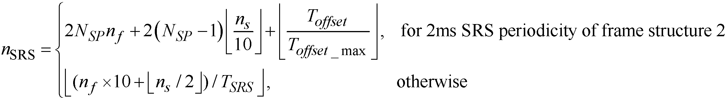
수학식 9에서 TSRS는 SRS 전송의 단말 특정 주기(periodicity), Toffset은 SRS 서브프레임 오프셋, Toffset_max는 SRS 서브프레임 오프셋의 특정 구성을 위한 Toffset 값의 최대값을 나타낸다. TSRS와 Toffset은 후술할 표 7 및 표 8에 의해서 주어질 수 있다.In Equation (9), T SRS represents the UE periodicity of the SRS transmission, T offset represents the SRS subframe offset, and T offset_max represents the maximum value of the T offset value for the specific configuration of the SRS subframe offset. T SRS and T offset can be given by Tables 7 and 8 below.
표 1 내지 표 4는 SRS 대역폭 구성의 일 예를 나타낸다. 3비트의 셀 특정 파라미터가 8개 중 하나의 대역폭 구성을 지시하기 위하여 브로드캐스트 될 수 있다. 또한, 2비트의 단말 특정 파라미터가 4개 중 하나의 대역폭 구성을 지시하기 위하여 상위 계층으로부터 주어질 수 있다.Tables 1 to 4 show an example of the SRS bandwidth configuration. 3 bits of cell specific parameters may be broadcast to indicate one of the eight bandwidth configurations. Further, a 2-bit terminal specific parameter may be given from the upper layer to indicate one of the four bandwidth configurations.
표 1은 상향링크 대역폭 NRB UL이 6≤NRB UL≤40의 범위일 때 mSRS,b 및 Nb(단, b=0,1,2,3)의 일 예이다.Table 1 is an example of an uplink bandwidth when N RB UL has in the range of 6≤N RB UL ≤40 m SRS, b and N b (stage, b = 0,1,2,3).
표 2는 상향링크 대역폭 NRB UL이 40≤NRB UL≤60의 범위일 때 mSRS,b 및 Nb(단, b=0,1,2,3)의 일 예이다.Table 2 is an example of an uplink bandwidth when N RB UL has in the range of 40≤N RB UL ≤60 m SRS, b and N b (stage, b = 0,1,2,3).
표 3은 상향링크 대역폭 NRB UL이 60≤NRB UL≤80의 범위일 때 mSRS,b 및 Nb(단, b=0,1,2,3)의 일 예이다.Table 3 is an example of an uplink bandwidth when N RB UL has in the range of 60≤N RB UL ≤80 m SRS, b and N b (stage, b = 0,1,2,3).
표 4는 상향링크 대역폭 NRB UL이 80≤NRB UL≤110의 범위일 때 mSRS,b 및 Nb(단, b=0,1,2,3)의 일 예이다.Table 4 is an example of an uplink bandwidth when N RB UL has in the range of 80≤N RB UL ≤110 m SRS, b and N b (stage, b = 0,1,2,3).
표 1 내지 표 4에서 셀 특정 파라미터인 CSRS∈{0,1,2,3,4,5,6,7}와 단말 특정 파라미터인 BSRS∈{0,1,2,3}은 상위 계층에 의해서 주어진다.In Table 1 to Table 4, the cell specific parameters C SRS? {0,1,2,3,4,5,6,7} and the terminal specific parameters B SRS? {0,1,2,3} Lt; / RTI >
표 5 및 표 6은 SRS 전송에 대한 셀 특정 서브프레임 구성 주기 파라미터 TSFC와 셀 특정 서브프레임 오프셋 파라미터 ΔSFC의 일 예이다.Table 5 and Table 6 is an example of a cell-specific subframe configuration for SRS transmission period parameter T and the SFC cell specific sub-frame offset parameter Δ SFC.
표 5는 FDD 시스템에서의 SRS 서브프레임 구성의 일 예이다. 표 5에 의하면 SRS 서브프레임 구성은 길이가 4비트인 파라미터에 의해 지시될 수 있으며, SRS 서브프레임의 주기는 1, 2, 5 및 10 서브프레임 중 어느 하나가 될 수 있다.Table 5 shows an example of the SRS subframe structure in the FDD system. According to Table 5, the SRS subframe structure can be indicated by a parameter having a length of 4 bits, and the period of the SRS subframe can be any one of 1, 2, 5, and 10 subframes.
TSFC (subframes) Configuration Period
T SFC (subframes)
표 6은 TDD 시스템에서의 SRS 서브프레임 구성의 일 예이다. Table 6 shows an example of the SRS subframe structure in the TDD system.
TSFC (subframes) Configuration Period
T SFC (subframes)
SRS의 전송을 위한 단말에서의 동작은 다음과 같다.Operation of the terminal for SRS transmission is as follows.
단말이 SRS를 전송할 때 전송 전력 PSRS는 수학식 10에 의해서 결정될 수 있다.The transmission power P SRS when the terminal transmits the SRS can be determined by Equation (10).
<수학식 10>&Quot; (10) "
![]()
![]()
수학식 10에서 i는 서브프레임 인덱스, PCMAX는 미리 지정된 단말의 전송 전력, PSRS_OFFSET은 상위 계층에 의해 결정되는 4비트 길이의 단말 특정 파라미터, MSRS는 인덱스가 i인 서브프레임에서 자원 블록의 개수로 나타낸 SRS 전송의 대역폭, f(i)는 PUSCH에 대한 현재 전력 제어 조정 상태를 나타낸다.In Equation (10), i denotes a subframe index, P CMAX denotes a predetermined transmission power of the UE, P SRS_OFFSET denotes a 4-bit length UE-specific parameter determined by an upper layer, and M SRS denotes a resource block The number of SRS transmission bandwidths, f (i), indicates the current power control adjustment state for the PUSCH.
단말이 전송 안테나 선택이 가능한 경우, nSRS 시간에 SRS를 전송하는 단말 안테나의 인덱스 a(nSRS)는 주파수 홉핑이 가능하지 않을 경우에는 전 사운딩 대역폭 또는 부분 사운딩 대역폭에 대하여 a(nSRS)=nSRS mod 2로 주어지며, 주파수 홉핑이 가능한 경우에는 수학식 11에 의해 주어질 수 있다.If the terminal is capable of transmitting antenna selection, the index of the terminal antenna for transmitting the SRS in n SRS time a (n SRS), if not available the frequency hopping, the entire sounding bandwidth or partial sound with respect to the coding bandwidth, a (n SRS ) = n SRS mod 2, and if frequency hopping is possible, it can be given by Equation (11).
<수학식 11>Equation (11)

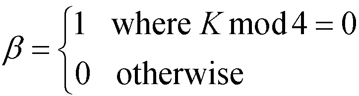
수학식 11에서 BSRS는 SRS 대역폭, bhop는 주파수 홉핑 대역폭을 나타낸다. Nb는 CSRS와 BSRS에 의해서 미리 결정된 표에 의해서 결정될 수 있다. 
수학식 11에서 β는 수학식 12에 의해서 결정될 수 있다.In Equation (11),? Can be determined by Equation (12).
<수학식 12>&Quot; (12) "
TDD 시스템에서 UpPTS(Uplink Pilot Time Slot) 내에 하나의 SC-FDMA 심벌이 존재하는 경우, 해당 SC-FDMA 심벌은 SRS 전송을 위하여 사용될 수 있다. UpPTS 내에 2개의 SC-FDMA 심벌이 존재하는 경우, 2개의 해당 SC-FDMA 심벌은 모두 SRS 전송을 위하여 사용될 수 있고, 하나의 단말에 동시에 할당될 수도 있다.If there is one SC-FDMA symbol in the Uplink Pilot Time Slot (UpPTS) in the TDD system, the corresponding SC-FDMA symbol may be used for SRS transmission. When there are two SC-FDMA symbols in the UpPTS, two corresponding SC-FDMA symbols may be used for SRS transmission and may be simultaneously allocated to one UE.
단말은 SRS의 전송과 PUCCH 포맷 2/2a/2b의 전송이 동일 서브프레임에서 동시에 발생하는 경우, 언제나 SRS을 전송하지 않는다.When the SRS transmission and the
단말은 ackNackSRS-SimultaneousTransmission 파라미터가 거짓(false)인 경우, SRS 전송과 ACK/NACK 및/또는 긍정(positive) SR을 나르는 PUCCH의 전송이 동일한 서브프레임에서 수행되면 언제나 SRS를 전송하지 않는다. 또한, 단말은 ackNackSRS-SimultaneousTransmission 파라미터가 참(true)인 경우, SRS 전송과 ACK/NACK 및/또는 긍정 SR을 나르는 PUCCH의 전송이 동일한 서브프레임에서 구성되면 축소된(shortened) PUCCH 포맷을 사용하며 ACK/NACK 및/또는 긍정 SR을 나르는 PUCCH와 SRS를 동시에 전송한다. 즉, 셀 특정하게 설정되는 SRS 서브프레임 내에 ACK/NACK 및/또는 긍정 SR을 나르는 PUCCH가 구성되는 경우에는 축소된(shortened) PUCCH 포맷을 사용하며 ACK/NACK 및/또는 긍정 SR을 나르는 PUCCH와 SRS를 동시에 전송한다. SRS 전송이 프리앰블(preamble) 포맷 4를 위한 PRACH(Physical Random Access Channel) 영역과 겹치거나 셀에서 구성된 상향링크 시스템 대역폭의 범위를 초과하는 경우에, 단말은 SRS를 전송하지 않는다.If the ackNackSRS-SimultaneousTransmission parameter is false, the UE does not transmit the SRS whenever the transmission of the SRS and the transmission of the PUCCH carrying the ACK / NACK and / or the positive SR are performed in the same subframe. If the ackNackSRS-SimultaneousTransmission parameter is true, the UE uses the shortened PUCCH format if the transmission of the SRS and the transmission of the PUCCH carrying the ACK / NACK and / or the positive SR are configured in the same subframe, And transmits PUCCH and SRS carrying / NACK and / or positive SR at the same time. That is, when a PUCCH for carrying ACK / NACK and / or ACK / NACK and / or ACK / NACK is configured in a cell-specific SRS subframe, a PUCCH and SRS At the same time. If the SRS transmission overlaps the PRACH (Physical Random Access Channel) region for
상위 계층에 의해 주어지는 파라미터인 ackNackSRS-SimultaneousTransmission는 단말이 ACK/NACK을 나르는 PUCCH와 SRS를 하나의 서브프레임에서 동시에 전송하는 것을 지원하는지 여부를 결정한다. 만약 단말이 ACK/NACK을 나르는 PUCCH와 SRS를 하나의 서브프레임에서 동시에 전송하기로 구성된다면, 단말은 셀 특정 SRS 서브프레임에서 ACK/NACK과 SRS을 전송할 수 있다. 이때 축소된(shortened) PUCCH 포맷이 사용될 수 있으며, SRS가 전송되는 위치에 대응되는 ACK/NACK 또는 SR의 전송은 생략된다(punctured). 축소된 PUCCH 포맷은 단말이 해당 서브프레임에서 SRS가 전송되지 않는 경우에도 셀 특정 SRS 서브프레임에서 사용된다. 만약 단말이 ACK/NACK을 나르는 PUCCH와 SRS를 하나의 서브프레임에서 동시에 전송하지 않기로 구성된다면, 단말은 ACK/NACK 및 SR의 전송을 위하여 일반적인 PUCCH 포맷 1/1a/1b를 사용할 수 있다.The parameter ackNackSRS-SimultaneousTransmission, which is a parameter given by the upper layer, determines whether the UE supports transmission of PUCCH and SRS carrying ACK / NACK in one subframe simultaneously. If the UE is configured to simultaneously transmit PUCCH and SRS carrying ACK / NACK in one subframe, the UE can transmit ACK / NACK and SRS in a cell specific SRS subframe. At this time, a shortened PUCCH format may be used, and the transmission of the ACK / NACK or SR corresponding to the location where the SRS is transmitted is punctured. The reduced PUCCH format is used in the cell specific SRS subframe even if the terminal does not transmit SRS in that subframe. If the UE is configured not to simultaneously transmit ACK / NACK PUCCH and SRS in one subframe, the UE can use a
표 7 및 표 8는 SRS 전송 주기인 TSRS와 SRS 서브프레임 오프셋인 Toffset을 지시하는 단말 특정 SRS 구성의 일 예이다. SRS 전송주기 TSRS는 {2, 5, 10, 20, 40, 80, 160, 320} ms 중 어느 하나로 결정될 수 있다.Tables 7 and 8 are examples of a UE-specific SRS configuration indicating SRS transmission period T SRS and SRS subframe offset T offset . The SRS transmission period T SRS may be determined to be {2, 5, 10, 20, 40, 80, 160, 320} ms.
표 7은 FDD 시스템에서의 SRS 구성의 일 예이다.Table 7 shows an example of the SRS configuration in the FDD system.
표 8은 TDD 시스템에서의 SRS 구성의 일 예이다.Table 8 is an example of the SRS configuration in the TDD system.
TDD 시스템에서 TSRS>2인 경우와 FDD 시스템에서 SRS 서브프레임은 (10*nf+kSRS-Toffset) mod TSRS=0을 만족한다. nf는 프레임 인덱스를 나타내며, kSRS는 FDD 시스템에서는 프레임 내에서의 서브프레임 인덱스이다. TDD 시스템에서 TSRS=2인 경우, 2개의 SRS 자원이 적어도 하나의 상향링크 서브프레임을 포함하는 반프레임 내에 구성될 수 있으며, SRS 서브프레임은 (kSRS-Toffset)mod5=0을 만족한다.In the case of T SRS > 2 in the TDD system and in the FDD system, the SRS subframe satisfies (10 * n f + k SRS -T offset ) mod T SRS = 0. n f denotes a frame index, and k SRS is a subframe index in a frame in the FDD system. In the TDD system, when T SRS = 2, two SRS resources can be configured in a half frame including at least one uplink sub-frame, and the SRS sub-frame satisfies (k SRS -T offset ) mod5 = 0 .
TDD 시스템에서 kSRS는 표 9에 의해서 결정될 수 있다.The k SRS in the TDD system can be determined by Table 9.
한편, 단말은 SRS의 전송과 임의 접속 응답 그랜트(Random Access Response Grant) 또는 경쟁 기반 임의 접속 절차의 일부로서 동일 전송 블록(transport block)의 재전송에 대응되는 PUSCH의 전송이 동일 서브프레임 내에서 수행되는 경우 언제나 SRS를 전송하지 않는다.On the other hand, if the transmission of the PUSCH corresponding to the retransmission of the same transport block is performed in the same subframe as part of the transmission of the SRS and the Random Access Response Grant or the contention-based random access procedure Do not always send SRS.
SRS 전송 방법은 2가지로 구분될 수 있다. LTE rel-8에서 정의된 방법으로 RRC(Radio Resource Control) 시그널링에 의해서 수신한 SRS 파라미터에 따라 주기적으로 SRS를 전송하는 주기적(periodic) SRS 전송 방법과, 기지국으로부터 동적(dynamic)으로 유발(trigger)되는 메시지를 기반으로 필요할 때마다 SRS를 전송하는 비주기적(aperiodic) SRS 전송 방법이 존재한다. LTE-A에서 비주기적 SRS 전송 방법이 도입될 수 있다.The SRS transmission method can be divided into two types. A periodic SRS transmission method that periodically transmits SRS according to SRS parameters received by RRC (Radio Resource Control) signaling in a method defined in LTE rel-8, and a method of dynamic triggering from a base station, There is an aperiodic SRS transmission method that transmits an SRS whenever necessary based on a message to be transmitted. An aperiodic SRS transmission method in LTE-A can be introduced.
한편, 주기적 SRS 전송 방법 및 비주기적 SRS 전송 방법에서 SRS는 단말 특정(UE-specific)하게 결정된 단말 특정 SRS 서브프레임에서 전송될 수 있다. LTE rel-8에서 정의된 주기적 SRS 전송 방법에서, 셀 특정 SRS 파라미터에 의해서 주기적으로 셀 특정 SRS 서브프레임이 설정되며 셀 특정 SRS 서브프레임 중 단말 특정 SRS 파라미터에 의해서 설정되는 주기적인 단말 특정 SRS 서브프레임에서 주기적 SRS가 전송된다. 이때 주기적인 단말 특정 SRS 서브프레임은 셀 특정 SRS 서브프레임의 부분 집합일 수 있다. 상기 셀 특정 SRS 파라미터는 상위 계층(higher layer)에 의해서 주어질 수 있다. 비주기적 SRS 전송 방법에서, 비주기적 SRS는 단말 특정 비주기적 SRS 파라미터에 의해서 결정되는 비주기적인 단말 특정 SRS 서브프레임에서 전송될 수 있다. 비주기적 SRS 전송 방법의 비주기적 단말 특정 SRS 서브프레임은 LTE rel-8에서 정의된 것과 같이 셀 특정 SRS 서브프레임의 부분 집합일 수 있다. 또는, 비주기적 단말 특정 SRS 서브프레임은 셀 특정 SRS 서브프레임과 동일할 수도 있다. 상기 단말 특정 비주기적 SRS 파라미터 또한 상기 셀 특정 SRS 파라미터와 마찬가지로 상위 계층에 의해서 주어질 수 있다. 단말 특정 비주기적 SRS 서브프레임은 앞에서 설명한 표 7 또는 표 8의 서브프레임 주기 및 서브프레임 오프셋에 의해서 설정될 수 있다. Meanwhile, in the periodic SRS transmission method and the aperiodic SRS transmission method, the SRS can be transmitted in a UE-specific determined UE-specific SRS sub-frame. In a periodic SRS transmission method defined in LTE rel-8, a cell-specific SRS subframe is periodically set by a cell-specific SRS parameter, and a periodic UE-specific SRS subframe set by a UE- The periodic SRS is transmitted. At this time, the periodic UE-specific SRS subframe may be a subset of the cell specific SRS subframe. The cell specific SRS parameter may be given by a higher layer. In the aperiodic SRS transmission method, the aperiodic SRS may be transmitted in an aperiodic terminal-specific SRS subframe determined by the terminal-specific aperiodic SRS parameter. The aperiodic UE-specific SRS subframe of the aperiodic SRS transmission method may be a subset of the cell specific SRS subframe as defined in LTE rel-8. Alternatively, the aperiodic UE-specific SRS subframe may be the same as the cell specific SRS subframe. The UE-specific aperiodic SRS parameter may also be given by the upper layer as well as the cell specific SRS parameter. The UE-specific aperiodic SRS subframe can be set by the subframe period and the subframe offset in Table 7 or Table 8 described above.
복수의 CC를 포함하는 반송파 집합 시스템에서, 비주기적 SRS가 전송되는 방법에 대해서는 아직 정의된 바가 없다. 즉, 기지국이 특정 DCI 포맷을 통해 단말에 비주기적 SRS의 전송을 요청하는 경우(기지국이 비주기적 SRS의 전송을 트리거(trigger)하는 경우), 단말이 어떤 UL CC를 통해 사운딩을 수행하는지에 대한 정보와 어떤 자원을 사용하여 사운딩을 수행하는지에 대한 정보가 필요하다. In a carrier aggregation system comprising a plurality of CCs, the manner in which aperiodic SRS is transmitted has not yet been defined. That is, when a base station requests transmission of an aperiodic SRS to a terminal through a specific DCI format (when the base station triggers transmission of an aperiodic SRS), the UE determines which UL CC performs sounding You need information about what you are doing and what resources you are using to do sounding.
이하, 실시예를 통해 본 발명을 설명하도록 한다.Hereinafter, the present invention will be described by way of examples.
도 10은 제안된 비주기적 SRS 전송 방법의 일 실시예를 나타낸다.10 shows an embodiment of the proposed aperiodic SRS transmission method.
단계 S100에서 단말은 복수의 UL CC 중 특정 UL CC를 통해 비주기적 SRS를 전송한다.In step S100, the UE transmits an aperiodic SRS through a specific UL CC among the plurality of UL CCs.
기지국이 비주기적 SRS의 전송을 1비트를 사용하여 트리거하는 경우, 단말은 다양한 방법으로 결정된 UL CC를 통해 비주기적 SRS를 전송할 수 있다.If the base station triggers the transmission of the aperiodic SRS using one bit, the terminal may transmit the aperiodic SRS through the determined UL CC in various ways.
1) 단말은 미리 결정된 UL CC를 통하여 비주기적 SRS를 전송할 수 있다. 이때 미리 결정된 UL CC는 PCC(Primary CC) 또는 SCC(Secondary CC) 중 어느 하나일 수 있고, PCC, 제2 CC 모두가 미리 결정된 CC가 될 수도 있다. 1) The UE can transmit aperiodic SRS through a predetermined UL CC. In this case, the predetermined UL CC may be either PCC (Primary CC) or SCC (Secondary CC), and both the PCC and the second CC may be a predetermined CC.
2) 단말은 RRC 시그널링 또는 L1/L2 제어 시그널링에 의해서 결정된 UL CC를 통해 비주기적 SRS를 전송할 수 있다. 비주기적 SRS가 전송되는 UL CC에 대한 정보가 L1/L2 시그널링을 통해 전송될 때, 이는 DL DCI 포맷 또는 UL DCI 포맷에 정의될 수 있다. DL DCI 포맷에 정의되는 경우, 반송파 지시자 필드(CIF; Carrier Indicator Field)에 의해 지시되는 UL CC를 통해 비주기적 SRS가 전송될 수 있다. 또는 다른 필드에 의해서 UL CC가 지시될 수 있다. 2) The UE may transmit aperiodic SRS through UL CC determined by RRC signaling or L1 / L2 control signaling. When information on the UL CC to which an aperiodic SRS is to be transmitted is transmitted via L1 / L2 signaling, it may be defined in the DL DCI format or the UL DCI format. When defined in the DL DCI format, an aperiodic SRS may be transmitted via a UL CC indicated by a Carrier Indicator Field (CIF). Or the UL CC may be indicated by another field.
3) 단말은 RRC 시그널링에 의해서 결정된 구성 UL CC(configured UL CC) 중 일부 UL CC를 통해 비주기적 SRS를 전송할 수도 있으며, 이때 SRS가 전송되는 일부 UL CC는 RRC 시그널링 또는 L1/L2 제어 시그널링(control signaling)에 의해서 지시될 수 있다. 3) The UE may transmit an aperiodic SRS through some UL CCs among the configured UL CCs determined by RRC signaling, wherein some UL CCs to which the SRS is transmitted may perform RRC signaling or L1 / L2 control signaling signaling.
4-1) 단말은 비주기적 SRS 전송을 트리거하는 메시지가 포함된 UL DCI 포맷을 전송하는 DL CC와 연결되어 있는 UL CC를 통해 비주기적 SRS를 전송 할 수 있다. 이때 DL CC와 UL CC의 연결은 SIB-2 연결 관계를 통해서 지시될 수 있다.4-1) The UE may transmit aperiodic SRS through the UL CC that is associated with the DL CC that transmits the UL DCI format containing the message that triggers the aperiodic SRS transmission. At this time, the connection between the DL CC and the UL CC can be indicated through the SIB-2 connection relationship.
4-2) 단말은 비주기적 SRS 전송을 트리거하는 메시지가 포함된 DL DCI 포맷을 전송하는 DL CC와 연결되어 있는 UL CC를 통해 비주기적 SRS를 전송 할 수 있다. 이때 DL CC와 UL CC의 연결은 SIB-2 연결 관계를 통해서 지시될 수 있다.4-2) The UE can transmit aperiodic SRS through a UL CC that is associated with a DL CC that transmits a DL DCI format containing a message that triggers an aperiodic SRS transmission. At this time, the connection between the DL CC and the UL CC can be indicated through the SIB-2 connection relationship.
4-3) 단말은 비주기적 SRS 전송을 트리거하는 메시지가 포함된 UL DCI 포맷에서 스케줄링 정보가 적용되는 UL CC를 통해 비주기적 SRS를 전송 할 수 있다. 스케줄링 정보가 적용되는 UL CC는 UL DCI 포맷 내의 CIF에 의해서 지시될 수 있다.4-3) The UE can transmit the aperiodic SRS through the UL CC to which the scheduling information is applied in the UL DCI format including the message triggering the aperiodic SRS transmission. The UL CC to which the scheduling information is applied may be indicated by the CIF in the UL DCI format.
4-4) 단말은 비주기적 SRS 전송을 트리거하는 메시지가 포함된 DL DCI 포맷에서 스케줄링 정보가 적용되는 DL CC와 연결되어 있는 UL CC를 통해 비주기적 SRS를 전송할 수 있다. 스케줄링 정보가 적용되는 UL CC는 DL DCI 포맷 내의 CIF에 의해서 지시될 수 있다.4-4) The UE can transmit the aperiodic SRS through the UL CC connected with the DL CC to which the scheduling information is applied in the DL DCI format including the message triggering the aperiodic SRS transmission. The UL CC to which the scheduling information is applied may be indicated by the CIF in the DL DCI format.
5) 동적으로(dynamically) 또는 반동적(semi-dynamically)으로 할당된 추가적인 제어 신호 필드를 통해서 비주기적 SRS가 전송되는 UL CC를 직접 지시할 수도 있다. 5) Directly indicate the UL CC through which the aperiodic SRS is transmitted through additional control signal fields that are dynamically or semi-dynamically assigned.
6) 단말의 상태나 전송 모드(MIMO 전송 모드 또는 비연속적(non-contiguous) RB 할당 기반 전송)의 설정 정보에 따라 암묵적으로(implicit) 결정된 UL CC를 통해 비주기적 SRS를 전송할 수 있다.6) may transmit an aperiodic SRS through an UL CC implicitly determined according to the state of the UE or the configuration information of the transmission mode (MIMO transmission mode or non-contiguous RB allocation based transmission).
UL CC 내에서 비주기적 SRS 전송을 위한 자원은 다양한 방법으로 할당될 수 있다.The resources for aperiodic SRS transmissions within the UL CC can be allocated in various ways.
1) 비주기적 SRS 전송을 위한 자원으로 주기적 SRS 전송을 위하여 사용되는 자원을 그대로 사용할 수 있다. 즉, RRC 시그널링 또는 L1/L2 제어 시그널링 등에 의해서 제공되는 셀 특정 SRS 대역폭 구성 정보, 단말 특정 SRS 대역폭 구성 정보, 전송 컴(transmission comb) 정보 등의 SRS 파라미터들을 기반으로 비주기적 SRS 전송을 위하여 자원이 할당될 수 있다.1) As a resource for non-periodic SRS transmission, resources used for periodic SRS transmission can be used as it is. That is, resources for SRS transmission based on SRS parameters such as cell specific SRS bandwidth configuration information, UE-specific SRS bandwidth configuration information, and transmission comb information provided by RRC signaling or L1 / L2 control signaling, Can be assigned.
2) 주기적 SRS를 위한 셀 특정 SRS 대역폭 구성 또는 단말 특정 SRS 대역폭 구성 등에 관계 없이, LTE rel-8/9에서 정의하는 각 시스템 대역폭 중에서 사용 가능한 전체(whole band) SRS 대역폭을 비주기적 SRS의 전송을 위하여 할당할 수 있다. 예를 들어, 시스템 대역폭이 5MHz인 경우 24 RB, 시스템 대역폭이 10MHz인 경우 48 RB, 시스템 대역폭이 15MHz인 경우 72 RB, 시스템 대역폭이 20MHz인 경우 96 RB를 비주기적 SRS의 전송을 위하여 할당한다. 하나의 서브프레임 내에서 비주기적 SRS의 전송을 위한 시간 자원은 주기적 SRS의 전송을 위하여 사용되는 서브프레임의 마지막 SC-FDMA 심벌일 수 있으며, 비주기적 SRS와 주기적 SRS는 다양한 방법으로 다중화(multiplexing) 될 수 있다.2) transmit the whole band SRS bandwidth defined by LTE rel-8/9 among all the system bandwidths, irrespective of cell-specific SRS bandwidth configuration or terminal-specific SRS bandwidth configuration for periodic SRS, . For example, 24 RB for a system bandwidth of 5 MHz, 48 RB for a system bandwidth of 10 MHz, 72 RB for a system bandwidth of 15 MHz, and 96 RB for a system bandwidth of 20 MHz for transmission of aperiodic SRS. The time resource for transmission of the aperiodic SRS in one subframe may be the last SC-FDMA symbol of the subframe used for transmission of the periodic SRS, and the aperiodic SRS and the periodic SRS may be multiplexed in various ways. .
3) 셀 특정 SRS 대역폭 구성에서 단말 특정하게 설정할 수 있는 SRS 대역폭 중 가장 큰 대역폭을 비주기적 SRS의 전송을 위하여 할당할 수 있다. 즉, 이는 표 1 내지 표 4에서 BSRS=0인 경우이다.3) The largest bandwidth of the SRS bandwidth that can be set in a UE-specific manner in a cell-specific SRS bandwidth configuration can be allocated for transmission of an aperiodic SRS. That is, this is a case where B SRS = 0 in Tables 1 to 4.
4) 셀 특정 SRS 대역폭 구성에서 단말 특정하게 설정할 수 있는 SRS 대역폭 중 일부 대역폭을 사용하여 비주기적 SRS를 전송할 수 있다. 예를 들어, 단말 특정하게 설정할 수 있는 SRS 대역폭을 분할하여 각 분할 대역폭을 통해 순서대로 비주기적 SRS를 전송할 수 있다. 각 분할 대역폭의 크기는 모두 같을 수 있다. 또는, 단말 특정하게 설정할 수 있는 SRS 대역폭의 최대값보다 큰 대역폭을 통해서 비주기적 SRS를 전송할 수도 있다. 이는 단말이 자신에게 할당된 단말 특정 SRS 대역폭과 다른 SRS 대역폭을 통해 비주기적 SRS를 보낼 수 있음을 의미한다.4) It is possible to transmit aperiodic SRS using some of the bandwidth of the SRS bandwidth that can be set UE-specific in the cell specific SRS bandwidth configuration. For example, it is possible to divide the SRS bandwidth that can be set in a UE-specific manner, and transmit the aperiodic SRS in order through each divided bandwidth. The size of each divided bandwidth may be the same. Alternatively, the UE may transmit the aperiodic SRS through a bandwidth greater than the maximum value of the SRS bandwidth that can be set to the UE-specific. This means that the UE can send an aperiodic SRS through the SRS bandwidth different from the UE-specific SRS bandwidth allocated to the UE.
5) 비주기적 SRS는 새롭게 정의되는 SRS 자원을 통해 전송될 수 있으며, SRS 자원은 DMRS 전송을 위하여 사용되는 자원을 포함할 수 있다.5) The aperiodic SRS may be transmitted through the newly defined SRS resource, and the SRS resource may include resources used for the DMRS transmission.
6) 비주기적 SRS는 시간 영역에서 DCI 포맷에 의한 시간 자원 또는 비주기적 SRS를 위한 특정 시간 자원을 통해 전송될 수 있다. 예를 들어, DL DCI에 의해서 비주기적 SRS가 트리거 되는 경우, 비주기적 SRS는 해당 DL DCI에 대응되는 UL 제어 신호가 전송되는 UL 서브프레임에서 전송되거나 해당 UL 서브프레임 이후 최초로 정의된 SRS 자원인 단말 특정 비주기적 SRS 서브프레임에서 전송될 수 있다. 또는, UL DCI에 의해서 비주기적 SRS가 트리거 되는 경우, 비주기적 SRS는 해당 UL 자원이 할당되는 UL 서브프레임에서 전송되거나 해당 UL 서브프레임 이후 최초로 정의된 SRS 자원인 단말 특정 비주기적 SRS 서브프레임에서 전송될 수 있다. 또는, 비주기적 SRS는 미리 결정되거나 다른 신호에 의해 지시되는 일정한 오프셋(offset)에 따라 전송되거나, 그 시점으로 최초로 사용 가능한 SRS 자원인 단말 특정 비주기적 SRS 서브프레임에서 전송될 수 있다.6) The aperiodic SRS can be transmitted in the time domain through the DCI format time resource or the specific time resource for aperiodic SRS. For example, when the aperiodic SRS is triggered by the DL DCI, the aperiodic SRS is transmitted in the UL subframe in which the UL control signal corresponding to the DL DCI is transmitted, or in the terminal May be transmitted in a specific aperiodic SRS subframe. Alternatively, when an aperiodic SRS is triggered by the UL DCI, the aperiodic SRS is transmitted in the UL sub-frame to which the UL resource is allocated or in the terminal-specific aperiodic SRS subframe that is the first defined SRS resource after the UL sub-frame . Alternatively, the aperiodic SRS may be transmitted in accordance with a predetermined offset, which is predetermined or indicated by another signal, or may be transmitted in a UE-specific aperiodic SRS sub-frame, which is the first available SRS resource at that time.
비주기적 SRS를 복수의 안테나를 통해 전송하기 위하여 다중화 할 수 있다.The aperiodic SRS may be multiplexed to transmit over a plurality of antennas.
1) 주기적 SRS는 RPF(Repetition Factor)=2에 의하여 다중 안테나를 통해 전송된다. 비주기적 SRS도 마찬가지로 RPF=2에 의하여 다중 안테나를 통해 전송될 수 있다. 이를 위해 서로 다른 전송 컴을 설정할 수 있고, 동일한 전송 컴 내에서 서로 다른 순환 쉬프트 값을 할당하여 CDM(Code Division Multiplexing) 방법으로 다중화할 수 있다.1) Periodic SRS is transmitted over multiple antennas by RPF (Repetition Factor) = 2. The aperiodic SRS can likewise be transmitted over multiple antennas by RPF = 2. For this purpose, different transmission systems can be set up, and different cyclic shift values can be assigned in the same transmission system and multiplexed by the CDM (Code Division Multiplexing) method.
2) RPF=2가 아닌 다른 RPF 값에 의해 비주기적 SRS를 다중 안테나를 통해 전송할 수 있다.2) Non-periodic SRS can be transmitted over multiple antennas by RPF value other than RPF = 2.
3) 또는, 복수의 안테나를 통해 비주기적 SRS를 전송하되, 모든 안테나에 대한 비주기적 SRS가 동시에 전송되지 않도록 할 수 있다. 즉, 비주기적 SRS를 전송함에 있어서, 각 안테나는 비주기적 SRS를 복수의 안테나를 통해 TDM(Time Division Multiplexing) 방식으로 다중화하여 전송할 수 있다. 이때 사용하는 자원은 각 안테나가 같은 자원을 사용하여 전송할 수 있다. 예를 들어 주기적 SRS의 전송을 위하여 할당된 자원을 비주기적 SRS의 전송을 위하여 사용할 수 있다.3) Alternatively, it is possible to transmit aperiodic SRS through a plurality of antennas, but not to transmit aperiodic SRS for all antennas at the same time. That is, in transmitting aperiodic SRS, each antenna may multiplex and transmit aperiodic SRS through a plurality of antennas in a TDM (Time Division Multiplexing) scheme. At this time, each antenna can transmit using the same resources. For example, resources allocated for transmission of periodic SRS may be used for transmission of aperiodic SRS.
한편, 특정 UL CC를 통해 전송되는 비주기적 SRS는 다른 UL CC를 통해 전송되는 다른 SRS와 동시에 전송될 수 있다. 비주기적 SRS가 전송되는 자원이 주기적 SRS가 전송되는 자원과 겹치지 않는 경우, 단말은 비주기적 SRS와 주기적 SRS를 동시에 전송할 수 있다. 이때 단말은 다양한 방법으로 비주기적 SRS와 주기적 SRS를 복수의 UL CC를 통해 전송할 수 있다. 예를 들어 비주기적 SRS가 전송되는 UL CC는 PCC 또는 앵커(anchor) CC와 SCC일 수 있다. 또는, 비주기적 SRS가 전송되는 UL CC는 RRC 시그널링에 의해서 결정된 구성 UL CC 중 일부 UL CC일 수 있으며, 이때 SRS가 전송되는 일부 UL CC들은 RRC 시그널링 또는 L1/L2 제어 시그널링에 의해서 지시될 수 있다.On the other hand, an aperiodic SRS transmitted through a specific UL CC can be transmitted simultaneously with another SRS transmitted through another UL CC. If the resource to which the aperiodic SRS is transmitted does not overlap with the resource to which the periodic SRS is transmitted, the UE can simultaneously transmit the aperiodic SRS and the periodic SRS. At this time, the UE can transmit aperiodic SRS and periodic SRS through a plurality of UL CCs in various ways. For example, the UL CC to which an aperiodic SRS is transmitted may be a PCC or an anchor CC and an SCC. Alternatively, the UL CC to which the aperiodic SRS is transmitted may be some UL CC of the constituent UL CC determined by the RRC signaling, wherein some UL CCs to which the SRS is transmitted may be indicated by RRC signaling or L1 / L2 control signaling .
또는 복수의 UL CC에 대한 비주기적 SRS가 하나의 UL CC를 통해서만 전송될 수 있다. UL 구성 CC 내에서 서브프레임 단위로 TDM 방식으로 다중화하여 하나의 UL CC를 통해 비주기적 SRS를 전송할 수 있다. 또는, PCC와 다른 UL CC가 TDM 방식으로 다중화될 수 있다. 또는, 비주기적 SRS의 전송을 트리거 하는 DL CC와 연결된 UL CC 내에서 서브프레임 단위로 TDM 방식으로 다중화하여 비주기적 SRS를 전송할 수 있다. 또는, DL CC와 UL CC의 연결 등에 상관 없이 모든 사용 가능한 UL CC에서 서브프레임 단위로 TDM 방식으로 다중화하여 비주기적 SRS를 전송할 수 있다. TDM 방식으로 다중화된 비주기적 SRS를 전송함에 있어서, 비주기적 SRS의 전송 순서는 기지국이 제어 신호를 통해 지시하거나 또는 미리 결정될 수 있다. 비주기적 SRS의 전송이 미리 RRC로 설정되어 있는 주기적 SRS의 전송과 겹치는 경우, 단말은 주기적 SRS의 전송을 생략(drop)하고, 비주기적 SRS의 전송만을 수행할 수 있다. 이때 주기적 SRS의 전송을 생략하는 것은 비주기적 SRS를 전송하는 UL CC와 주기적 SRS를 전송하는 UL CC가 동일한 UL CC일 때만 적용될 수 있다. 또는, 비주기적 SRS를 전송하는 UL CC와 주기적 SRS를 전송하는 UL CC가 서로 다른 경우에도 주기적 SRS의 전송을 생략하고 비주기적 SRS의 전송만을 수행할 수 있다.Or an aperiodic SRS for a plurality of UL CCs can only be transmitted through one UL CC. It is possible to transmit aperiodic SRS through one UL CC by multiplexing in TDM manner in units of subframes within UL configuration CC. Alternatively, a UL CC different from the PCC may be multiplexed in a TDM manner. Alternatively, non-periodic SRS can be transmitted by multiplexing in a TDM manner in sub-frame units within a UL CC connected with DL CC triggering transmission of aperiodic SRS. Or, non-periodic SRS can be transmitted by multiplexing in the TDM scheme in every available subframe in all usable UL CC irrespective of DL CC and UL CC connection. In transmitting the TDM-multiplexed aperiodic SRS, the transmission order of the aperiodic SRS may be indicated by a base station via a control signal or may be predetermined. If the transmission of the aperiodic SRS overlaps with the transmission of the periodic SRS set in advance to the RRC, the UE may drop the transmission of the periodic SRS and perform only the transmission of the aperiodic SRS. At this time, omitting the transmission of the periodic SRS can be applied only when the UL CC transmitting the aperiodic SRS and the UL CC transmitting the periodic SRS are the same UL CC. Or, even if the UL CC transmitting the aperiodic SRS and the UL CC transmitting the periodic SRS are different, transmission of the periodic SRS may be omitted and only transmission of the aperiodic SRS may be performed.
도 11은 본 발명의 실시예가 구현되는 기지국 및 단말의 블록도이다. 11 is a block diagram of a base station and a terminal in which an embodiment of the present invention is implemented.
기지국(800)은 프로세서(810; processor), 메모리(820; memory) 및 RF부(830; Radio Frequency unit)을 포함한다. 프로세서(810)는 제안된 기능, 과정 및/또는 방법을 구현한다. 무선 인터페이스 프로토콜의 계층들은 프로세서(810)에 의해 구현될 수 있다. 메모리(820)는 프로세서(810)와 연결되어, 프로세서(810)를 구동하기 위한 다양한 정보를 저장한다. RF부(830)는 프로세서(810)와 연결되어, 무선 신호를 전송 및/또는 수신한다.The
단말(900)은 프로세서(910), 메모리(920) 및 RF부(930)을 포함한다. 프로세서(910)는 제안된 기능, 과정 및/또는 방법을 구현한다. 무선 인터페이스 프로토콜의 계층들은 프로세서(910)에 의해 구현될 수 있다. 메모리(920)는 프로세서(910)와 연결되어, 프로세서(910)를 구동하기 위한 다양한 정보를 저장한다. RF부(930)는 프로세서(910)와 연결되어, 복수의 UL CC 중 특정 UL CC를 통해 비주기적 SRS를 전송한다. 상기 특정 UL CC는 상향링크 그랜트에 의해 스케줄링되는 PUSCH가 전송되는 UL CC와 동일한 UL CC이며, 상기 상향링크 그랜트는 상기 비주기적 SRS의 전송을 트리거(trigger)하는 메시지를 포함한다.The terminal 900 includes a
프로세서(810, 910)은 ASIC(application-specific integrated circuit), 다른 칩셋, 논리 회로 및/또는 데이터 처리 장치를 포함할 수 있다. 메모리(820, 920)는 ROM(read-only memory), RAM(random access memory), 플래쉬 메모리, 메모리 카드, 저장 매체 및/또는 다른 저장 장치를 포함할 수 있다. RF부(830, 930)은 무선 신호를 처리하기 위한 베이스밴드 회로를 포함할 수 있다. 실시예가 소프트웨어로 구현될 때, 상술한 기법은 상술한 기능을 수행하는 모듈(과정, 기능 등)로 구현될 수 있다. 모듈은 메모리(820, 920)에 저장되고, 프로세서(810, 910)에 의해 실행될 수 있다. 메모리(820, 920)는 프로세서(810, 910) 내부 또는 외부에 있을 수 있고, 잘 알려진 다양한 수단으로 프로세서(810, 910)와 연결될 수 있다.
상술한 예시적인 시스템에서, 방법들은 일련의 단계 또는 블록으로써 순서도를 기초로 설명되고 있지만, 본 발명은 단계들의 순서에 한정되는 것은 아니며, 어떤 단계는 상술한 바와 다른 단계와 다른 순서로 또는 동시에 발생할 수 있다. 또한, 당업자라면 순서도에 나타낸 단계들이 배타적이지 않고, 다른 단계가 포함되거나 순서도의 하나 또는 그 이상의 단계가 본 발명의 범위에 영향을 미치지 않고 삭제될 수 있음을 이해할 수 있을 것이다. In the above-described exemplary system, the methods are described on the basis of a flowchart as a series of steps or blocks, but the present invention is not limited to the order of the steps, and some steps may occur in different orders . It will also be understood by those skilled in the art that the steps shown in the flowchart are not exclusive and that other steps may be included or that one or more steps in the flowchart may be deleted without affecting the scope of the invention.
상술한 실시예들은 다양한 양태의 예시들을 포함한다. 다양한 양태들을 나타내기 위한 모든 가능한 조합을 기술할 수는 없지만, 해당 기술 분야의 통상의 지식을 가진 자는 다른 조합이 가능함을 인식할 수 있을 것이다. 따라서, 본 발명은 이하의 특허청구범위 내에 속하는 모든 다른 교체, 수정 및 변경을 포함한다고 할 것이다.The above-described embodiments include examples of various aspects. While it is not possible to describe every possible combination for expressing various aspects, one of ordinary skill in the art will recognize that other combinations are possible. Accordingly, it is intended that the invention include all alternatives, modifications and variations that fall within the scope of the following claims.
Claims (16)
상기 비주기적 SRS의 전송을 트리거 하는 SRS 요청을 포함하는 DCI(downlink control information)를 PDCCH(physical downlink control channel)를 통해 수신하고;
상기 SRS 요청을 검출하고;
CIF(carrier indicator field)가 구성되면, 복수의 상향링크(UL; uplink) 구성 반송파(CC; component carrier) 중 상기 CIF에 대응하는 UL CC 상으로 상기 비주기적 SRS를 전송하고; 및
CIF가 구성되지 않으면, 상기 복수의 UL CC 중 상기 DCI에 의해 PUSCH(physical uplink shared channel)가 스케줄링 되는 UL CC 상으로 상기 비주기적 SRS를 전송하는 것을 포함하며,
상기 비주기적 SRS는 상기 UL CC 내의 주파수 자원과 시간 자원을 통해 전송되며,
상기 UL CC 내의 상기 주파수 자원은 UE 특정 대역폭 구성 정보에 의하여 구성되며,
상기 UL CC 내의 상기 시간 자원은 상기 DCI에 대응하는 UL 자원이 할당되는 UL 서브프레임이며,
상기 비주기적 SRS는 반복 팩터 2에 의하여 복수의 안테나를 통해 전송되는 것을 특징으로 하는 방법.A method of transmitting an aperiodic SRS (sounding reference signal) by a user equipment (UE) in a wireless communication system,
Receive downlink control information (DCI) including an SRS request that triggers transmission of the aperiodic SRS over a physical downlink control channel (PDCCH);
Detecting the SRS request;
When the carrier indicator field (CIF) is configured, transmitting the aperiodic SRS onto a plurality of uplink (UL) constituent carriers on the UL CC corresponding to the CIF; And
If the CIF is not configured, sending the aperiodic SRS onto the UL CC on which a physical uplink shared channel (PUSCH) is scheduled by the DCI of the plurality of UL CCs,
The aperiodic SRS is transmitted through a frequency resource and a time resource in the UL CC,
The frequency resources in the UL CC are configured by UE specific bandwidth configuration information,
The time resources in the UL CC are UL subframes to which a UL resource corresponding to the DCI is allocated,
Wherein the aperiodic SRS is transmitted via a plurality of antennas by a repetition factor 2. 2. The method of claim < RTI ID = 0.0 > 1, < / RTI >
상기 CIF가 구성되면 상기 CIF가 상기 DCI에 포함되는 것을 특징으로 하는 방법.The method according to claim 1,
Wherein when the CIF is configured, the CIF is included in the DCI.
상기 DCI는 상기 UL CC와 연결된 DL CC 상으로 상기 PDCCH를 통해 수신되는 것을 특징으로 하는 방법.The method according to claim 1,
And the DCI is received on the PDCCH on the DL CC associated with the UL CC.
상기 UL CC와 상기 DL CC의 연결은 시스템 정보(system information)에 의해 지시되는 것을 특징으로 하는 방법.5. The method of claim 4,
Wherein the connection between the UL CC and the DL CC is indicated by system information.
상기 비주기적 SRS는 상기 UL CC 내에서 주기적(periodic) SRS의 전송을 위하여 사용되는 자원에 할당되어 전송되는 것을 특징으로 하는 방법.The method according to claim 1,
Wherein the aperiodic SRS is allocated and transmitted to a resource used for transmission of a periodic SRS in the UL CC.
상기 비주기적 SRS는 상기 UL CC 내에서 각 시스템 대역폭 중에서 사용 가능한 전체 SRS 대역폭에 할당되어 전송되는 것을 특징으로 하는 방법.The method according to claim 1,
Wherein the aperiodic SRS is allocated and allocated to a total available SRS bandwidth in each UL system bandwidth within the UL CC.
상기 비주기적 SRS는 상기 UL CC 내에서 단말 특정(UE-specific)하게 결정되는 SRS 대역폭 중 가장 큰 대역폭에 할당되어 전송되는 것을 특징으로 하는 방법.The method according to claim 1,
Wherein the aperiodic SRS is allocated to the largest bandwidth of the SRS bandwidth determined UE-specific within the UL CC.
상기 비주기적 SRS는 상기 UL CC 내에서 단말 특정하게 결정되는 SRS 대역폭의 일부에 할당되어 전송되는 것을 특징으로 하는 방법.The method according to claim 1,
Wherein the aperiodic SRS is allocated and transmitted in a portion of the SRS bandwidth determined to be UE-specific within the UL CC.
상기 비주기적 SRS는 복수의 안테나를 통해 전송되는 것을 특징으로 하는 방법.The method according to claim 1,
Wherein the aperiodic SRS is transmitted via a plurality of antennas.
RF(radio frequency)부; 및
상기 RF부와 연결되는 프로세서를 포함하되,
상기 프로세서는,
비주기적 SRS의 전송을 트리거 하는 SRS 요청을 포함하는 DCI(downlink control information)를 PDCCH(physical downlink control channel)를 통해 수신하도록 상기 RF를 제어하고,
상기 SRS 요청을 검출하고,
CIF(carrier indicator field)가 구성되면, 복수의 상향링크(UL; uplink) 구성 반송파(CC; component carrier) 중 상기 CIF에 대응하는 UL CC 상으로 상기 비주기적 SRS를 전송하도록 상기 RF부를 제어하고, 및
CIF가 구성되지 않으면, 상기 복수의 UL CC 중 상기 DCI에 의해 PUSCH(physical uplink shared channel)가 스케줄링 되는 UL CC 상으로 상기 비주기적 SRS를 전송하도록 상기 RF를 제어하도록 구성되며,
상기 비주기적 SRS는 상기 UL CC 내의 주파수 자원과 시간 자원을 통해 전송되며,
상기 UL CC 내의 상기 주파수 자원은 UE 특정 대역폭 구성 정보에 의하여 구성되며,
상기 UL CC 내의 상기 시간 자원은 상기 DCI에 대응하는 UL 자원이 할당되는 UL 서브프레임이며,
상기 비주기적 SRS는 반복 팩터 2에 의하여 복수의 안테나를 통해 전송되는 것을 특징으로 하는 단말. A terminal in a wireless communication system,
A radio frequency (RF) unit; And
And a processor coupled to the RF unit,
The processor comprising:
Controlling the RF to receive downlink control information (DCI) including an SRS request that triggers transmission of an aperiodic SRS over a physical downlink control channel (PDCCH)
Detecting the SRS request,
Control the RF unit to transmit the aperiodic SRS on a UL CC corresponding to the CIF among a plurality of uplink constituent carriers (CCs) when a carrier indicator field (CIF) is configured, And
If the CIF is not configured, control the RF to transmit the aperiodic SRS onto a UL CC of which the physical uplink shared channel (PUSCH) is scheduled by the DCI of the plurality of UL CCs,
The aperiodic SRS is transmitted through a frequency resource and a time resource in the UL CC,
The frequency resources in the UL CC are configured by UE specific bandwidth configuration information,
The time resources in the UL CC are UL subframes to which a UL resource corresponding to the DCI is allocated,
Wherein the aperiodic SRS is transmitted via a plurality of antennas by a repetition factor 2. 2. The UE of claim 1,
상기 CIF가 구성되면 상기 CIF가 상기 DCI에 포함되는 것을 특징으로 하는 단말.12. The method of claim 11,
Wherein the CIF is included in the DCI when the CIF is configured.
상기 DCI는 상기 UL CC와 연결된 DL CC 상으로 상기 PDCCH를 통해 수신되는 것을 특징으로 하는 단말.12. The method of claim 11,
Wherein the DCI is received on the PDCCH on a DL CC associated with the UL CC.
상기 UL CC와 상기 DL CC의 연결은 시스템 정보(system information)에 의해 지시되는 것을 특징으로 하는 단말.15. The method of claim 14,
Wherein the connection between the UL CC and the DL CC is indicated by system information.
Priority Applications (10)
| Application Number | Priority Date | Filing Date | Title |
|---|---|---|---|
| KR1020110019404A KR101807874B1 (en) | 2010-03-05 | 2011-03-04 | Method and apparatus of transmitting aperiodic sounding reference signal in wireless communication system |
| CN201180004880.4A CN102742194B (en) | 2010-03-05 | 2011-03-07 | Method and device for aperiodic transmission of sounding reference signal in wireless communication system |
| CA2782315A CA2782315C (en) | 2010-03-05 | 2011-03-07 | Aperiodic transmission method and apparatus for sounding reference signal in wireless communication system |
| JP2012538778A JP5625065B2 (en) | 2010-03-05 | 2011-03-07 | Method and apparatus for transmitting aperiodic sounding reference signal in wireless communication system |
| AU2011221690A AU2011221690B2 (en) | 2010-03-05 | 2011-03-07 | Aperiodic transmission method and apparatus for sounding reference signal in wireless communication system |
| PCT/KR2011/001546 WO2011108905A2 (en) | 2010-03-05 | 2011-03-07 | Aperiodic transmission method and apparatus for sounding reference signal in wireless communication system |
| EP11750962.0A EP2495901A4 (en) | 2010-03-05 | 2011-03-07 | Aperiodic transmission method and apparatus for sounding reference signal in wireless communication system |
| US13/509,486 US8787289B2 (en) | 2010-03-05 | 2011-03-07 | Aperiodic transmission method and apparatus for sounding reference signal in wireless communication system |
| US14/316,641 US9226280B2 (en) | 2010-03-05 | 2014-06-26 | Aperiodic transmission method and apparatus for sounding reference signal in wireless communication system |
| US14/961,518 US9485760B2 (en) | 2010-03-05 | 2015-12-07 | Aperiodic transmission method and apparatus for sounding reference signal in wireless communication system |
Applications Claiming Priority (3)
| Application Number | Priority Date | Filing Date | Title |
|---|---|---|---|
| US31071210P | 2010-03-05 | 2010-03-05 | |
| US61/310,712 | 2010-03-05 | ||
| KR1020110019404A KR101807874B1 (en) | 2010-03-05 | 2011-03-04 | Method and apparatus of transmitting aperiodic sounding reference signal in wireless communication system |
Publications (2)
| Publication Number | Publication Date |
|---|---|
| KR20110101087A KR20110101087A (en) | 2011-09-15 |
| KR101807874B1 true KR101807874B1 (en) | 2017-12-12 |
Family
ID=44542755
Family Applications (1)
| Application Number | Title | Priority Date | Filing Date |
|---|---|---|---|
| KR1020110019404A Expired - Fee Related KR101807874B1 (en) | 2010-03-05 | 2011-03-04 | Method and apparatus of transmitting aperiodic sounding reference signal in wireless communication system |
Country Status (8)
| Country | Link |
|---|---|
| US (3) | US8787289B2 (en) |
| EP (1) | EP2495901A4 (en) |
| JP (1) | JP5625065B2 (en) |
| KR (1) | KR101807874B1 (en) |
| CN (1) | CN102742194B (en) |
| AU (1) | AU2011221690B2 (en) |
| CA (1) | CA2782315C (en) |
| WO (1) | WO2011108905A2 (en) |
Families Citing this family (38)
| Publication number | Priority date | Publication date | Assignee | Title |
|---|---|---|---|---|
| JP5538930B2 (en) | 2010-02-04 | 2014-07-02 | シャープ株式会社 | Mobile station apparatus, base station apparatus, radio communication system, and radio communication method |
| JP5132723B2 (en) * | 2010-02-15 | 2013-01-30 | 株式会社エヌ・ティ・ティ・ドコモ | Reference signal transmission method, mobile station apparatus and base station apparatus |
| KR101807874B1 (en) * | 2010-03-05 | 2017-12-12 | 엘지전자 주식회사 | Method and apparatus of transmitting aperiodic sounding reference signal in wireless communication system |
| US8917593B2 (en) * | 2010-03-18 | 2014-12-23 | Qualcomm Incorporated | Random access design in a multiple component carrier communication network |
| CN102083219B (en) * | 2010-03-31 | 2014-04-09 | 电信科学技术研究院 | Method and equipment for transmitting non-periodic SRS (Sounding Reference Signal) |
| KR101487072B1 (en) * | 2010-03-31 | 2015-01-28 | 후지쯔 가부시끼가이샤 | Radio communication system, radio communication apparatus, and radio communication method |
| WO2011134153A1 (en) * | 2010-04-29 | 2011-11-03 | 富士通株式会社 | Method and apparatus for aperiodically transmitting sounding reference signal |
| BR112012027810B1 (en) | 2010-04-30 | 2021-08-17 | Sun Patent Trust | WIRELESS COMMUNICATION DEVICE AND METHOD FOR CONTROLLING TRANSMISSION POWER |
| US20110274063A1 (en) * | 2010-05-10 | 2011-11-10 | Ming-Che Li | Method and apparatus for handling dynamic aperiodic srs (sounding reference signal) in a wireless communication network |
| US9762372B2 (en) | 2010-06-15 | 2017-09-12 | Texas Instruments Incorporated | CSI reporting on PUSCH for carrier aggregation |
| US8861451B2 (en) | 2010-08-13 | 2014-10-14 | Qualcomm Incorporated | Method and apparatus of deactivating carriers in wireless communications |
| KR101468344B1 (en) * | 2010-08-13 | 2014-12-10 | 블랙베리 리미티드 | Method of resource allocation and signaling for aperiodic channel sounding |
| CN102469607B (en) * | 2010-11-09 | 2014-01-22 | 上海贝尔股份有限公司 | Methods and equipment for triggering and transmitting uplink sounding reference signal (SRS) |
| CN103314627B (en) * | 2011-01-07 | 2017-11-14 | 富士通株式会社 | Trigger method, base station and the user equipment of aperiodic measuring reference signals |
| WO2012108804A1 (en) * | 2011-02-10 | 2012-08-16 | Telefonaktiebolaget L M Ericsson (Publ) | Reference signal resource allocation in a multi-carrier system |
| JP5499065B2 (en) * | 2011-04-01 | 2014-05-21 | 創新音▲速▼股▲ふん▼有限公司 | Setting method, communication apparatus and computer program in radio communication system |
| WO2013038716A1 (en) * | 2011-09-16 | 2013-03-21 | パナソニック株式会社 | Wireless transmission device, wireless reception device, and wireless communication method |
| WO2013055116A1 (en) * | 2011-10-11 | 2013-04-18 | 엘지전자 주식회사 | Method and device for transmitting data in wireless communication system |
| US8966277B2 (en) | 2013-03-15 | 2015-02-24 | Mitsubishi Electric Research Laboratories, Inc. | Method for authenticating an encryption of biometric data |
| US9078241B2 (en) | 2013-03-22 | 2015-07-07 | Sharp Kabushiki Kaisha | Systems and methods for establishing multiple radio connections |
| US11558894B2 (en) | 2015-03-02 | 2023-01-17 | Apple Inc. | Aperiodic scheduling of uplink grants in a wireless communication system |
| KR101923455B1 (en) | 2015-04-10 | 2018-11-29 | 엘지전자 주식회사 | Method of transmitting or receiving a sounding reference signal in a wireless communication system and Apparatus thereof |
| US10348543B2 (en) | 2016-01-29 | 2019-07-09 | Ofinno, Llc | Uplink transmission in a wireless device and wireless network |
| US10716125B2 (en) | 2016-04-01 | 2020-07-14 | Qualcomm Incorporated | Sounding reference signal triggering for enhanced carrier aggregation |
| WO2018081954A1 (en) * | 2016-11-02 | 2018-05-11 | 广东欧珀移动通信有限公司 | Communication method, terminal device and network device |
| KR102270085B1 (en) * | 2017-05-01 | 2021-06-28 | 엘지전자 주식회사 | Sounding method for terminal in wireless communication system and apparatus therefor |
| WO2019074266A1 (en) * | 2017-10-10 | 2019-04-18 | 엘지전자 주식회사 | Method for transmitting and receiving srs and communication device therefor |
| CN113660188B (en) * | 2017-11-17 | 2024-12-20 | 华为技术有限公司 | Method and device for sending sounding reference signal SRS |
| US10938524B2 (en) * | 2018-01-24 | 2021-03-02 | Qualcomm Incorporated | Timing for reference signals in multiple numerology wireless communications |
| US11234262B2 (en) | 2018-02-15 | 2022-01-25 | Qualcomm Incorporated | Configuration of aperiodic sounding reference signal transmission and triggering |
| US11088791B2 (en) * | 2018-05-21 | 2021-08-10 | Qualcomm Incorporated | Choosing an SRS resource set when multiple sets are configured |
| KR20210066916A (en) | 2018-10-26 | 2021-06-07 | 텔레폰악티에볼라겟엘엠에릭슨(펍) | Implicit sounding reference signal aperiodic trigger offset |
| KR20210096271A (en) * | 2018-12-07 | 2021-08-04 | 후아웨이 테크놀러지 컴퍼니 리미티드 | SRS transmission method, SRS reception method and device |
| CN111417199B (en) * | 2019-01-07 | 2023-01-13 | 中国移动通信有限公司研究院 | CLI measurement reference signal configuration, transceiving method, device, medium and equipment |
| WO2021216706A1 (en) * | 2020-04-21 | 2021-10-28 | Qualcomm Incorporated | Flexible cross-carrier aperiodic sounding reference signal triggering enhancement |
| US12278716B2 (en) * | 2020-05-14 | 2025-04-15 | Qualcomm Incorporated | SRS carrier switching for additional SRS |
| US20230216632A1 (en) * | 2020-06-09 | 2023-07-06 | Lg Electronics Inc. | Method and device for transmitting or receiving sounding reference signal in wireless communication system |
| EP4222904A4 (en) * | 2020-09-29 | 2023-11-08 | ZTE Corporation | Method and device for sounding reference signal indication enhancement |
Family Cites Families (19)
| Publication number | Priority date | Publication date | Assignee | Title |
|---|---|---|---|---|
| US8417248B2 (en) * | 2006-08-14 | 2013-04-09 | Texas Instruments Incorporated | Methods and apparatus to schedule uplink transmissions in wireless communication systems |
| KR20080020934A (en) * | 2006-09-01 | 2008-03-06 | 한국전자통신연구원 | Uplink Signal Transmission Method, Transmission Device, Generation Method, and Generation Device in Communication System |
| US8107987B2 (en) * | 2007-02-14 | 2012-01-31 | Qualcomm Incorporated | Apparatus and method for uplink power control of wireless communications |
| US8086272B2 (en) | 2007-08-06 | 2011-12-27 | Mitsubishi Electric Research Laboratories, Inc. | Wireless networks incorporating antenna selection based on received sounding reference signals |
| US20090046645A1 (en) * | 2007-08-13 | 2009-02-19 | Pierre Bertrand | Uplink Reference Signal Sequence Assignments in Wireless Networks |
| US9893859B2 (en) * | 2007-10-30 | 2018-02-13 | Texas Instruments Incorporated | Transmission of sounding reference signal and scheduling request in single carrier systems |
| KR101376838B1 (en) * | 2008-01-04 | 2014-03-20 | 엘지전자 주식회사 | Uplink Control Signal Transmission Method |
| US8295778B2 (en) * | 2008-01-11 | 2012-10-23 | Apple Inc. | Channel rank feedback in multiple-input multiple-output communication systems |
| JP2011514723A (en) * | 2008-02-01 | 2011-05-06 | リサーチ イン モーション リミテッド | System and method for uplink timing synchronization associated with discontinuous reception |
| PL2260607T3 (en) * | 2008-03-31 | 2018-07-31 | Telefonaktiebolaget Lm Ericsson (Publ) | Method and apparatus for transmitting csi on the pusch in an lte system |
| KR101441147B1 (en) * | 2008-08-12 | 2014-09-18 | 엘지전자 주식회사 | Method of transmitting sr in wireless communication system |
| JP5547734B2 (en) * | 2008-09-26 | 2014-07-16 | サムスン エレクトロニクス カンパニー リミテッド | Apparatus and method for supporting transmission of sounding reference signal from multiple antennas |
| US20130153298A1 (en) * | 2009-02-19 | 2013-06-20 | Interdigital Patent Holdings, Inc. | Method and apparatus for enhancing cell-edge user performance and signaling radio link failure conditions via downlink cooperative component carriers |
| TWI530216B (en) * | 2009-03-17 | 2016-04-11 | Interdigital Patent Holdings | Sounding reference signal (SRS) transmission power control method and device |
| EP2497218B1 (en) * | 2009-11-02 | 2019-09-04 | Nokia Solutions and Networks Oy | Sounding reference signal configuration |
| US8848520B2 (en) * | 2010-02-10 | 2014-09-30 | Qualcomm Incorporated | Aperiodic sounding reference signal transmission method and apparatus |
| KR101807875B1 (en) | 2010-03-05 | 2017-12-12 | 엘지전자 주식회사 | Method and apparatus of transmitting aperiodic sounding reference signal in wireless communication system |
| KR101807874B1 (en) * | 2010-03-05 | 2017-12-12 | 엘지전자 주식회사 | Method and apparatus of transmitting aperiodic sounding reference signal in wireless communication system |
| JP2012204999A (en) | 2011-03-24 | 2012-10-22 | Panasonic Corp | Relay system, relay device, and relay method |
-
2011
- 2011-03-04 KR KR1020110019404A patent/KR101807874B1/en not_active Expired - Fee Related
- 2011-03-07 US US13/509,486 patent/US8787289B2/en active Active
- 2011-03-07 CA CA2782315A patent/CA2782315C/en active Active
- 2011-03-07 AU AU2011221690A patent/AU2011221690B2/en active Active
- 2011-03-07 WO PCT/KR2011/001546 patent/WO2011108905A2/en not_active Ceased
- 2011-03-07 CN CN201180004880.4A patent/CN102742194B/en not_active Expired - Fee Related
- 2011-03-07 EP EP11750962.0A patent/EP2495901A4/en not_active Withdrawn
- 2011-03-07 JP JP2012538778A patent/JP5625065B2/en active Active
-
2014
- 2014-06-26 US US14/316,641 patent/US9226280B2/en active Active
-
2015
- 2015-12-07 US US14/961,518 patent/US9485760B2/en active Active
Non-Patent Citations (5)
| Title |
|---|
| 3GPP R1-093837* |
| 3GPP R1-093902* |
| 3GPP R1-100337* |
| 3GPP R1-101134* |
| 3GPP TS 36.211 v9.0.0* |
Also Published As
| Publication number | Publication date |
|---|---|
| CN102742194B (en) | 2016-08-10 |
| AU2011221690B2 (en) | 2014-07-24 |
| US20140328273A1 (en) | 2014-11-06 |
| WO2011108905A3 (en) | 2012-01-12 |
| EP2495901A4 (en) | 2013-12-11 |
| CA2782315A1 (en) | 2011-09-09 |
| EP2495901A2 (en) | 2012-09-05 |
| US8787289B2 (en) | 2014-07-22 |
| CN102742194A (en) | 2012-10-17 |
| WO2011108905A2 (en) | 2011-09-09 |
| US9485760B2 (en) | 2016-11-01 |
| JP2013510539A (en) | 2013-03-21 |
| AU2011221690A1 (en) | 2012-05-31 |
| CA2782315C (en) | 2017-02-28 |
| US9226280B2 (en) | 2015-12-29 |
| US20120263129A1 (en) | 2012-10-18 |
| JP5625065B2 (en) | 2014-11-12 |
| KR20110101087A (en) | 2011-09-15 |
| US20160088614A1 (en) | 2016-03-24 |
Similar Documents
| Publication | Publication Date | Title |
|---|---|---|
| KR101807874B1 (en) | Method and apparatus of transmitting aperiodic sounding reference signal in wireless communication system | |
| KR101807875B1 (en) | Method and apparatus of transmitting aperiodic sounding reference signal in wireless communication system | |
| KR101791266B1 (en) | Method and apparatus of transmitting data in wireless communication system | |
| US10411857B2 (en) | Method and apparatus for transmitting aperiodic sounding reference signal in wireless communication system | |
| KR101327131B1 (en) | Method and apparatus of transmitting data in wireless communication system | |
| US8953483B2 (en) | Method and apparatus for transmitting aperiodic sounding reference signal in wireless communication system | |
| KR101328213B1 (en) | Method and apparatus of transmitting data in wireless communication system | |
| US8913578B2 (en) | Method and apparatus for transmitting aperiodic sounding reference signals in a wireless communication system | |
| US9210001B2 (en) | Method and apparatus for transmitting aperiodic sounding reference signal in wireless communication system | |
| WO2012115472A2 (en) | Method and device for transmitting data in wireless communication system | |
| KR20120008473A (en) | Method and apparatus for aperiodic sounding reference signal transmission in wireless communication system | |
| CN102742195B (en) | Method and device for aperiodic transmission of sounding reference signal in wireless communication system |
Legal Events
| Date | Code | Title | Description |
|---|---|---|---|
| PA0109 | Patent application |
St.27 status event code: A-0-1-A10-A12-nap-PA0109 |
|
| PG1501 | Laying open of application |
St.27 status event code: A-1-1-Q10-Q12-nap-PG1501 |
|
| R17-X000 | Change to representative recorded |
St.27 status event code: A-3-3-R10-R17-oth-X000 |
|
| PN2301 | Change of applicant |
St.27 status event code: A-3-3-R10-R13-asn-PN2301 St.27 status event code: A-3-3-R10-R11-asn-PN2301 |
|
| AMND | Amendment | ||
| E13-X000 | Pre-grant limitation requested |
St.27 status event code: A-2-3-E10-E13-lim-X000 |
|
| P11-X000 | Amendment of application requested |
St.27 status event code: A-2-2-P10-P11-nap-X000 |
|
| P13-X000 | Application amended |
St.27 status event code: A-2-2-P10-P13-nap-X000 |
|
| PA0201 | Request for examination |
St.27 status event code: A-1-2-D10-D11-exm-PA0201 |
|
| E902 | Notification of reason for refusal | ||
| PE0902 | Notice of grounds for rejection |
St.27 status event code: A-1-2-D10-D21-exm-PE0902 |
|
| AMND | Amendment | ||
| P11-X000 | Amendment of application requested |
St.27 status event code: A-2-2-P10-P11-nap-X000 |
|
| P13-X000 | Application amended |
St.27 status event code: A-2-2-P10-P13-nap-X000 |
|
| E601 | Decision to refuse application | ||
| PE0601 | Decision on rejection of patent |
St.27 status event code: N-2-6-B10-B15-exm-PE0601 |
|
| AMND | Amendment | ||
| E13-X000 | Pre-grant limitation requested |
St.27 status event code: A-2-3-E10-E13-lim-X000 |
|
| P11-X000 | Amendment of application requested |
St.27 status event code: A-2-2-P10-P11-nap-X000 |
|
| P13-X000 | Application amended |
St.27 status event code: A-2-2-P10-P13-nap-X000 |
|
| PX0901 | Re-examination |
St.27 status event code: A-2-3-E10-E12-rex-PX0901 |
|
| PX0701 | Decision of registration after re-examination |
St.27 status event code: A-3-4-F10-F13-rex-PX0701 |
|
| X701 | Decision to grant (after re-examination) | ||
| GRNT | Written decision to grant | ||
| PR0701 | Registration of establishment |
St.27 status event code: A-2-4-F10-F11-exm-PR0701 |
|
| PR1002 | Payment of registration fee |
St.27 status event code: A-2-2-U10-U11-oth-PR1002 Fee payment year number: 1 |
|
| PG1601 | Publication of registration |
St.27 status event code: A-4-4-Q10-Q13-nap-PG1601 |
|
| PN2301 | Change of applicant |
St.27 status event code: A-5-5-R10-R13-asn-PN2301 St.27 status event code: A-5-5-R10-R11-asn-PN2301 |
|
| PR1001 | Payment of annual fee |
St.27 status event code: A-4-4-U10-U11-oth-PR1001 Fee payment year number: 4 |
|
| PR1001 | Payment of annual fee |
St.27 status event code: A-4-4-U10-U11-oth-PR1001 Fee payment year number: 5 |
|
| P22-X000 | Classification modified |
St.27 status event code: A-4-4-P10-P22-nap-X000 |
|
| PR1001 | Payment of annual fee |
St.27 status event code: A-4-4-U10-U11-oth-PR1001 Fee payment year number: 6 |
|
| P22-X000 | Classification modified |
St.27 status event code: A-4-4-P10-P22-nap-X000 |
|
| PC1903 | Unpaid annual fee |
St.27 status event code: A-4-4-U10-U13-oth-PC1903 Not in force date: 20231206 Payment event data comment text: Termination Category : DEFAULT_OF_REGISTRATION_FEE |
|
| P22-X000 | Classification modified |
St.27 status event code: A-4-4-P10-P22-nap-X000 |
|
| PC1903 | Unpaid annual fee |
St.27 status event code: N-4-6-H10-H13-oth-PC1903 Ip right cessation event data comment text: Termination Category : DEFAULT_OF_REGISTRATION_FEE Not in force date: 20231206 |