KR101803617B1 - Polarization-sensitive optical coherence tomography imaging system - Google Patents
Polarization-sensitive optical coherence tomography imaging system Download PDFInfo
- Publication number
- KR101803617B1 KR101803617B1 KR1020150167798A KR20150167798A KR101803617B1 KR 101803617 B1 KR101803617 B1 KR 101803617B1 KR 1020150167798 A KR1020150167798 A KR 1020150167798A KR 20150167798 A KR20150167798 A KR 20150167798A KR 101803617 B1 KR101803617 B1 KR 101803617B1
- Authority
- KR
- South Korea
- Prior art keywords
- light
- prostate
- nerve
- reflected
- image
- Prior art date
- Legal status (The legal status is an assumption and is not a legal conclusion. Google has not performed a legal analysis and makes no representation as to the accuracy of the status listed.)
- Active
Links
- 238000003384 imaging method Methods 0.000 title claims abstract description 47
- 230000010287 polarization Effects 0.000 title abstract description 33
- 238000012014 optical coherence tomography Methods 0.000 title description 4
- 210000002307 prostate Anatomy 0.000 claims abstract description 96
- 210000005036 nerve Anatomy 0.000 claims abstract description 58
- 230000003287 optical effect Effects 0.000 claims abstract description 56
- 210000002808 connective tissue Anatomy 0.000 claims abstract description 34
- 239000012528 membrane Substances 0.000 claims abstract description 31
- 238000001514 detection method Methods 0.000 claims abstract description 27
- 230000001427 coherent effect Effects 0.000 claims abstract description 25
- 210000001519 tissue Anatomy 0.000 claims description 21
- 238000012545 processing Methods 0.000 claims description 10
- 238000000034 method Methods 0.000 claims description 7
- 210000003899 penis Anatomy 0.000 claims description 7
- 208000003098 Ganglion Cysts Diseases 0.000 claims description 6
- 208000005400 Synovial Cyst Diseases 0.000 claims description 6
- 210000004907 gland Anatomy 0.000 claims description 5
- 210000000664 rectum Anatomy 0.000 claims description 5
- 210000003932 urinary bladder Anatomy 0.000 claims description 5
- 230000001678 irradiating effect Effects 0.000 claims description 2
- 230000003902 lesion Effects 0.000 abstract description 14
- 238000003325 tomography Methods 0.000 abstract description 11
- 238000001356 surgical procedure Methods 0.000 abstract description 6
- 208000028389 Nerve injury Diseases 0.000 abstract description 4
- 230000008764 nerve damage Effects 0.000 abstract description 4
- 210000000056 organ Anatomy 0.000 abstract description 2
- 230000006866 deterioration Effects 0.000 abstract 1
- 239000000523 sample Substances 0.000 description 13
- 239000000835 fiber Substances 0.000 description 9
- 230000008901 benefit Effects 0.000 description 6
- 238000002567 electromyography Methods 0.000 description 6
- 238000011471 prostatectomy Methods 0.000 description 6
- 238000010171 animal model Methods 0.000 description 4
- 230000000694 effects Effects 0.000 description 4
- 210000002569 neuron Anatomy 0.000 description 4
- 230000008859 change Effects 0.000 description 3
- 230000006870 function Effects 0.000 description 3
- 238000002357 laparoscopic surgery Methods 0.000 description 3
- 239000013307 optical fiber Substances 0.000 description 3
- 238000004321 preservation Methods 0.000 description 3
- 238000012546 transfer Methods 0.000 description 3
- FWBHETKCLVMNFS-UHFFFAOYSA-N 4',6-Diamino-2-phenylindol Chemical compound C1=CC(C(=N)N)=CC=C1C1=CC2=CC=C(C(N)=N)C=C2N1 FWBHETKCLVMNFS-UHFFFAOYSA-N 0.000 description 2
- 210000004204 blood vessel Anatomy 0.000 description 2
- 210000005226 corpus cavernosum Anatomy 0.000 description 2
- 238000010586 diagram Methods 0.000 description 2
- 238000007689 inspection Methods 0.000 description 2
- 238000002324 minimally invasive surgery Methods 0.000 description 2
- 238000002610 neuroimaging Methods 0.000 description 2
- 210000004977 neurovascular bundle Anatomy 0.000 description 2
- 238000011160 research Methods 0.000 description 2
- 238000002432 robotic surgery Methods 0.000 description 2
- 238000012360 testing method Methods 0.000 description 2
- 208000000094 Chronic Pain Diseases 0.000 description 1
- 208000010228 Erectile Dysfunction Diseases 0.000 description 1
- 208000002193 Pain Diseases 0.000 description 1
- 206010033799 Paralysis Diseases 0.000 description 1
- 208000035965 Postoperative Complications Diseases 0.000 description 1
- 206010046543 Urinary incontinence Diseases 0.000 description 1
- 210000001789 adipocyte Anatomy 0.000 description 1
- 210000000577 adipose tissue Anatomy 0.000 description 1
- 210000000013 bile duct Anatomy 0.000 description 1
- 238000001574 biopsy Methods 0.000 description 1
- 238000013480 data collection Methods 0.000 description 1
- 238000011161 development Methods 0.000 description 1
- 230000018109 developmental process Effects 0.000 description 1
- 238000005516 engineering process Methods 0.000 description 1
- 230000007274 generation of a signal involved in cell-cell signaling Effects 0.000 description 1
- 238000010166 immunofluorescence Methods 0.000 description 1
- 201000001881 impotence Diseases 0.000 description 1
- 238000012986 modification Methods 0.000 description 1
- 230000004048 modification Effects 0.000 description 1
- 210000004126 nerve fiber Anatomy 0.000 description 1
- 210000000944 nerve tissue Anatomy 0.000 description 1
- 230000001272 neurogenic effect Effects 0.000 description 1
- 230000000926 neurological effect Effects 0.000 description 1
- 230000035515 penetration Effects 0.000 description 1
- 230000002093 peripheral effect Effects 0.000 description 1
- 230000036299 sexual function Effects 0.000 description 1
- 230000008054 signal transmission Effects 0.000 description 1
- 230000000638 stimulation Effects 0.000 description 1
- 230000001960 triggered effect Effects 0.000 description 1
- 210000000626 ureter Anatomy 0.000 description 1
- 230000000007 visual effect Effects 0.000 description 1
Images


Classifications
-
- A—HUMAN NECESSITIES
- A61—MEDICAL OR VETERINARY SCIENCE; HYGIENE
- A61B—DIAGNOSIS; SURGERY; IDENTIFICATION
- A61B5/00—Measuring for diagnostic purposes; Identification of persons
- A61B5/0059—Measuring for diagnostic purposes; Identification of persons using light, e.g. diagnosis by transillumination, diascopy, fluorescence
- A61B5/0062—Arrangements for scanning
- A61B5/0064—Body surface scanning
-
- A—HUMAN NECESSITIES
- A61—MEDICAL OR VETERINARY SCIENCE; HYGIENE
- A61B—DIAGNOSIS; SURGERY; IDENTIFICATION
- A61B5/00—Measuring for diagnostic purposes; Identification of persons
- A61B5/0033—Features or image-related aspects of imaging apparatus, e.g. for MRI, optical tomography or impedance tomography apparatus; Arrangements of imaging apparatus in a room
-
- A—HUMAN NECESSITIES
- A61—MEDICAL OR VETERINARY SCIENCE; HYGIENE
- A61B—DIAGNOSIS; SURGERY; IDENTIFICATION
- A61B5/00—Measuring for diagnostic purposes; Identification of persons
- A61B5/40—Detecting, measuring or recording for evaluating the nervous system
-
- A—HUMAN NECESSITIES
- A61—MEDICAL OR VETERINARY SCIENCE; HYGIENE
- A61B—DIAGNOSIS; SURGERY; IDENTIFICATION
- A61B5/00—Measuring for diagnostic purposes; Identification of persons
- A61B5/43—Detecting, measuring or recording for evaluating the reproductive systems
- A61B5/4375—Detecting, measuring or recording for evaluating the reproductive systems for evaluating the male reproductive system
- A61B5/4381—Prostate evaluation or disorder diagnosis
Landscapes
- Health & Medical Sciences (AREA)
- Life Sciences & Earth Sciences (AREA)
- Heart & Thoracic Surgery (AREA)
- Surgery (AREA)
- Physics & Mathematics (AREA)
- Veterinary Medicine (AREA)
- Biophysics (AREA)
- Pathology (AREA)
- Engineering & Computer Science (AREA)
- Biomedical Technology (AREA)
- Public Health (AREA)
- Medical Informatics (AREA)
- Molecular Biology (AREA)
- General Health & Medical Sciences (AREA)
- Animal Behavior & Ethology (AREA)
- Nuclear Medicine, Radiotherapy & Molecular Imaging (AREA)
- Radiology & Medical Imaging (AREA)
- Physiology (AREA)
- Neurology (AREA)
- Neurosurgery (AREA)
- Gynecology & Obstetrics (AREA)
- Reproductive Health (AREA)
- Investigating Or Analysing Materials By Optical Means (AREA)
Abstract
본 발명은 전립선의 결합조직성 막과 신경을 실시간으로 시각화할 수 있는 편광 민감 광 간섭 단층영상시스템을 제공하기 위하여, 광원 및 상기 광원으로부터 제공되는 광을 기준광과 조사광으로 분할하는 광분할부 및 상기 광분할부에 연결되어 상기 광분할부로부터 상기 기준광이 제공되는 레퍼런스암 및 상기 광분할부에 연결되어, 상기 광분할부로부터 제공되는 조사광을 수평광과 수직광으로 편광시키는 샘플암 및 상기 샘플암에 연결되어, 상기 평광이 상기 전립선을 향해 조사되는 조사경로와 상기 전립선으로부터의 반사광의 입사경로를 형성하는 탐지부 및 상기 탐지부로 입사되는 상기 반사광을 검출하여 상기 전립선의 복굴절영상정보를 획득하고, 상기 기준광과 상기 반사광의 간섭신호로 상기 전립선의 구조영상정보를 획득하는 검출부를 포함한다. 이에, 결합조직성 막과 신경을 시각화하여 시술자에게 실시간 영상을 제공하는 바, 병변 제거 시 신경의 손상을 절감시킬 수 있어 수술 후 기관 기능 저하를 감소시키고 수술의 성공률을 증대시킬 수 있는 효과가 있다. The present invention provides a polarization-sensitive optical coherent tomography imaging system capable of visualizing the connective tissue membrane and nerve of the prostate in real time, comprising a light source and a light splitting unit for splitting the light provided from the light source into reference light and irradiation light, A sample arm which is connected to the light dividing unit and is connected to the reference arm and the light dividing unit provided with the reference light from the light dividing unit to polarize the irradiation light provided from the light dividing unit into normal light and vertical light, A detection unit which forms an irradiation path for the light to be irradiated toward the prostate gland and an incident path for reflected light from the prostate gland, and a detector for detecting the reflected light incident on the detection unit to obtain birefringence image information of the prostate, A detector for acquiring structural image information of the prostate with an interference signal of the reflected light; It includes. Therefore, it is possible to visualize the connective tissue membrane and the nerve to provide real-time images to the operator, which can reduce nerve damage during the removal of the lesion, thereby reducing the deterioration of the organ function after surgery and increasing the success rate of surgery .
Description
본 발명은 편광 민감 광 간섭 단층영상시스템에 관한 것으로, 보다 상세하게는 전립선 병변 제거시 주변 신경 영상화에 사용되는 편광 민감 광 간섭 단층영상시스템에 관한 것이다. The present invention relates to a polarization-sensitive optical coherence tomography imaging system, and more particularly, to a polarization-sensitive optical coherence tomography imaging system for use in peripheral neuroimaging in the removal of a prostate lesion.
일반적으로 정밀 수술의 성공률 향상을 위해서는 병변의 제거뿐만 아니라 신경, 혈관, 요관, 담관 등 기관 기능의 중요부위에 대한 손상 최소화가 요구된다. 특히, 신경의 손상은 만성통증 및 연구마비 등과 같은 수술 후유증을 유발시킬 수 있어 수술 시 신경 보존을 위한 다양한 연구 개발이 활발히 진행되고 있다. In general, minimization of damage to important parts of the organ function such as nerve, blood vessel, ureter and bile duct as well as removal of lesion is required to improve the success rate of precision surgery. In particular, since nerve damage can lead to postoperative complications such as chronic pain and research paralysis, various researches and developments have been actively carried out for nerve preservation during surgery.
다만, 신경은 육안으로의 탐지가 어렵기 때문에 병변 제거 시 쉽게 손상될 수 있어 신경 탐지를 위한 근전도 검사(Electromyography)가 이용되고 있다. 근전도 검사는 해부학적 연관성을 기반으로 신경이 위치하고 있을 것으로 추측되는 영역에 전기 자극을 가하여 신경의 상태를 확인하는 것을 특징으로 한다. However, because the nerve is difficult to detect with the naked eye, electromyography is used to detect neurons, which can easily be damaged when the lesion is removed. The electromyography test is characterized in that the state of the nerve is confirmed by applying electrical stimulation to the region where the nerve is supposed to be located based on the anatomical relation.
이러한 근전도 검사에 대한 종래 기술은 이미 "대한민국 공개특허공보 제2002-0077346호(근전도검사 시스템, 2002.10.11.)"에 의해 개시된 바 있다. 상기 공개특허는 프로브를 기반으로 프로브 말단부에 인접하는 신경의 상태를 확인하는 것을 특징으로 한다. The prior art for such EMG examination has already been disclosed in Korean Patent Laid-Open Publication No. 2002-0077346 (Electromyography Inspection System, October 11, 2002). The present invention is characterized by confirming the state of the nerve adjacent to the probe tip based on the probe.
다만, 종래의 근전도 검사는 신경의 직관적 탐지가 어려워 신경의 시각적 위치 탐지가 요구되는 수술에서는 적용이 어려운 문제점이 있었다. 특히, 전립선 절제술과 같이 전립선 관련 수술의 경우 전립선이 여러 층의 결합조직성 막으로 감싸져 있고 여러 층의 결합조직성 막 사이에 신경이 존재하게 되므로 수술 시 결합조직성 막과 신경을 실시간으로 시각화할 수 있는 기술이 요구되고 있다. However, the conventional electromyography test has a problem in that it is difficult to intuitively detect the nerve, and thus it is difficult to apply it to an operation requiring visual position detection of the nerve. In particular, prostate-related surgery, such as prostatectomy, is surrounded by multiple layers of connective tissue and multiple layers of connective tissue, so that the connective tissue membranes and nerves are visualized in real time A technology that can be used is required.
본 발명의 목적은 전립선의 결합조직성 막과 신경을 실시간으로 시각화할 수 있는 편광 민감 광 간섭 단층영상시스템을 제공하기 위한 것이다.It is an object of the present invention to provide a polarization sensitive optical coherence tomography imaging system capable of visualizing in real time the connective tissue membranes and nerves of the prostate gland.
본 발명에 따른 편광 민감 광 간섭 단층영상장치는 광원 및 상기 광원으로부터 제공되는 광을 기준광과 조사광으로 분할하는 광분할부 및 상기 광분할부에 연결되어 상기 기준광의 진행 경로를 형성하는 레퍼런스암 및 상기 광분할부로부터 제공되는 상기 조사광이 타겟위치인 전립선 부위로 제공되는 경로를 형성하고, 상기 조사광을 수평성분과 수직성분으로 편광시키는 광학부재를 포함하는 샘플암 및 상기 레퍼런스암을 통과한 상기 기준광과, 상기 샘플암으로부터 반사된 반사광을 수광하여 상기 전립선 부위의 영상 정보를 검출하는 검출부를 포함하고, 상기 검출부는 상기 기준광과 상기 반사광의 간섭신호를 이용하여 상기 전립선 부위의 구조 영상 정보를 획득하고, 상기 전립선 부위로부터 반사된 상기 수평성분과 상기 수직성분을 이용하여 상기 전립선 부위의 복굴절 영상 정보를 획득한다.A polarization-sensitive optical coherent tomography imaging apparatus according to the present invention includes a light source and a light splitting unit that splits light provided from the light source into reference light and irradiation light, and a reference arm connected to the light splitting unit to form a path of the reference light, A sample arm including an optical member that forms a path provided to the prostate portion as a target position and that polarizes the irradiation light into a horizontal component and a vertical component, and a reference arm that passes through the reference arm, And a detector for receiving reflected light reflected from the sample arm and detecting image information of the prostate part, wherein the detector acquires structural image information of the prostate region using an interference signal between the reference light and the reflected light, Using the horizontal component reflected from the prostate part and the vertical component And acquires birefringence image information of the prostate region.
상기 샘플암은 상기 수평성분과 상기 수직성분이 광로차를 가지고 상기 전립선 부위로 조사되도록 하고, 상기 전립선 부위로부터 반사된 상기 수평성분과 상기 수직성분은 광로차를 가지고 각각 수광될 수 있다.The horizontal arm and the vertical arm of the sample arm are irradiated to the prostate part with an optical path difference, and the horizontal component and the vertical component reflected from the prostate part are respectively received with an optical path difference.
상기 샘플암으로부터 조사된 상기 수평성분과 상기 수직성분은 상기 전립선 부위로부터 반사되며, 상기 전립선 부위의 복굴절 특성에 기초하여 상기 전립선 부위의 결합 조직성 막과 신경의 조직 특성정보가 검출되도록 할 수 있다.The horizontal component and the vertical component irradiated from the sample arm are reflected from the prostate part and tissue characteristic information of the connective tissue membrane and the nerve of the prostate part may be detected based on the birefringence characteristic of the prostate part .
상기 편광 민감 광 간섭 단층영상장치는 상기 검출부에 연결되어, 상기 결합조직성 막과 상기 신경의 복굴절영상 및 구조영상을 각각 디스플레이하는 영상 처리부를 더 포함하고, 상기 결합조직성 막과 상기 신경은 상기 복굴절 영상에서 상호 상이한 형태로 디스플레이될 수 있다. The polarized light sensitive optical coherent tomographic imaging apparatus further includes an image processing unit connected to the detection unit and displaying a birefringence image and a structural image of the nerve tissue and the nerve respectively, Can be displayed in mutually different forms in a birefringence image.
상기 복굴절 영상에서 상기 신경은 상기 결합조직성 막과 구별되도록 상기 결합조직성 막 상에 섬유성 형태로 디스플레이될 수 있다. In the birefringence image, the nerve may be displayed in fibrous form on the connective tissue membrane to be distinct from the connective tissue membrane.
상기 복굴절 영상 정보는 신경절(Ganglion)부터 방광, 직장, 및 음경으로 향하는 갈래의 신경 다발에 대한 조직 특성 정보를 포함하고, 상기 구조 영상 정보는 전립선 주변의 그랜드 구조(Gland Structure)와 지방에 대한 구조 정보를 포함할 수 있다. The birefringence image information includes tissue characteristic information on the nerve bundles of the forked nerve from the ganglion to the bladder, rectum, and penis, and the structure image information includes the gland structure around the prostate gland and the structure Information.
상기 검출부는 상기 반사광으로부터 음경 해면체 신경에 대한 조직 특성 정보를 검출할 수 있다.The detection unit may detect tissue characteristic information on the penile sponge nerve from the reflected light.
한편, 본 발명에 따른 편광 민감 광 간섭 단층영상방법은 광원으로부터 제공되는 광을 기준광과 조사광으로 분할하는 단계 및 상기 조사광을 수평성분과 수직성분으로 편광시키는 단계 및 상기 수평성분과 상기 수직성분을 타겟위치인 전립선 부위로 조사하는 단계 및 상기 기준광과, 상기 전립선 부위로부터 반사된 반사광을 수광하여 상기 전립선 부위의 영상 정보를 검출하는 단계를 포함하고, 상기 검출하는 단계는 상기 기준광과 상기 반사광의 간섭신호를 이용하여 상기 전립선 부위의 구조 영상 정보를 획득하고, 상기 전립선 부위로부터 반사된 상기 수평성분과 상기 수직성분을 이용하여 상기 전립선 부위의 복굴절 영상 정보를 획득한다.Meanwhile, the polarization-sensitive optical coherent tomography imaging method according to the present invention includes the steps of dividing light provided from a light source into reference light and irradiation light, polarizing the irradiation light into a horizontal component and a vertical component, And detecting the image information of the prostate part by receiving the reflected light reflected from the reference light and the prostate part and detecting the image information of the prostate part, Obtains the structural image information of the prostate region using the interference signal, and obtains the birefringence image information of the prostate region using the horizontal component and the vertical component reflected from the prostate region.
상기 조사하는 단계는 상기 수평성분과 상기 수직성분이 광로차를 가지고 상기 전립선 분위로 조사되고, 상기 전립선 부위로부터 반사된 상기 수평성분과 상기 수직성분은 광로차를 가지고 각각 수광될 수 있다. In the step of irradiating, the horizontal component and the vertical component may be irradiated to the prostatic segment, with the optical path difference, and the horizontal component and the vertical component reflected from the prostate portion may be respectively received with an optical path difference.
상기 검출하는 단계는 상기 수평성분과 상기 수직성분이 상기 전립선 부위로부터 반사되며, 상기 전립선 부위의 복굴절 특성에 기초하여 상기 전립선 부위의 결합 조직성 막과 신경의 조직 특성정보가 검출되도록 할 수 있다.In the detecting step, the horizontal component and the vertical component are reflected from the prostate part, and the tissue characteristic information of the connective tissue membrane and the nerve of the prostate part may be detected based on the birefringence characteristic of the prostate part.
상기 편광 민감 광 간섭 단층영상방법은 상기 검출하는 단계 이후에 상기 결합 조직성막과 상기 신경의 복굴절영상 및 구조영상을 각각 디스플레이하는 단계를 더 포함하고, 상기 결합조직성 막과 상기 신경은 상기 복굴절 영상에서 상호 상이한 형태로 디스플레이될 수 있다. Wherein the polarization sensitive optical coherent tomography imaging method further comprises displaying the combined tissue membrane and the birefringent image and the structural image of the nerve after the detecting step, As shown in FIG.
상기 디스플레이하는 단계는 상기 복굴절영상에서 상기 신경이 상기 결합조직성 막과 구별되도록 상기 결합조직성 막 상에 섬유성 형태로 디스플레이될 수 있다. The displaying may be displayed in a fibrous form on the connective tissue membrane such that the nerve is distinct from the connective tissue membrane in the birefringence image.
상기 복굴절 영상 정보는 신경절(Ganglion)부터 방광, 직장, 및 음경으로 향하는 갈래의 신경 다발에 대한 조직 특성 정보를 포함하고, 상기 구조 영상 정보는 전립선 주변의 그랜드 구조(Gland Structure)와 지방에 대한 구조 정보를 포함할 수 있다. The birefringence image information includes tissue characteristic information on the nerve bundles of the forked nerve from the ganglion to the bladder, rectum, and penis, and the structure image information includes the gland structure around the prostate gland and the structure Information.
상기 검출하는 단계는 상기 반사광으로부터 음경 해면체 신경에 대한 조직 특성 정보를 검출할 수 있다.The detecting step may detect tissue characteristic information on the penile cavernosal nerve from the reflected light.
본 발명에 따른 편광 민감 광 간섭 단층영상시스템은 결합조직성 막과 신경을 시각화하여 시술자에게 실시간 영상을 제공하는 바, 병변 제거 시 신경의 손상을 절감시킬 수 있어 수술 후 기관 기능 저하를 감소시키고 수술의 성공률을 증대시킬 수 있는 효과가 있다. The polarization-sensitive optical coherent tomographic imaging system according to the present invention visualizes connective tissue membranes and nerves and provides real-time images to the practitioner. It can reduce nerve damage during lesion removal, It is possible to increase the success rate of the operation.
이상과 같은 본 발명의 기술적 효과는 이상에서 언급한 효과로 제한되지 않으며, 언급되지 않은 또 다른 기술적 효과들은 아래의 기재로부터 당업자에게 명확하게 이해될 수 있을 것이다.The technical effects of the present invention are not limited to the effects mentioned above, and other technical effects not mentioned can be clearly understood by those skilled in the art from the following description.
도 1은 본 실시예에 따른 편광 민감 광 간섭 단층영상장치를 나타낸 구성도이고,
도 2는 본 실시예에 따른 편광 민감 광 간섭 단층영상방법을 나타낸 흐름도이고,
도 3은 본 실시예에 따른 편광 민감 광 간섭 단층영상시스템을 이용하여 동물모델의 전립선과 주변 조직을 촬영한 도면이고,
도 4는 본 실시예에 따른 편광 민감 광 간섭 단층영상시스템을 이용하여 환자의 전립선과 주변 조직을 촬영한 도면이다. FIG. 1 is a configuration diagram illustrating a polarization-sensitive optical coherent tomographic imaging apparatus according to an embodiment of the present invention,
FIG. 2 is a flowchart illustrating a polarization-sensitive optical coherent tomographic imaging method according to the present embodiment,
FIG. 3 is a photograph of the prostate and surrounding tissues of an animal model using the polarization-sensitive optical coherent tomography imaging system according to the present embodiment,
FIG. 4 is a photograph of a patient's prostate and surrounding tissues using the polarization-sensitive optical coherent tomography imaging system according to the present embodiment.
이하 첨부된 도면을 참조하여 본 발명의 실시예를 상세히 설명한다. 그러나 본 실시예는 이하에서 개시되는 실시예에 한정되는 것이 아니라 서로 다양한 형태로 구현될 수 있으며, 단지 본 실시예는 본 발명의 개시가 완전하도록 하며, 통상의 지식을 가진 자에게 발명의 범주를 완전하게 알려주기 위해 제공되는 것이다. 도면에서의 요소의 형상 등은 보다 명확한 설명을 위하여 과장되게 표현된 부분이 있을 수 있으며, 도면 상에서 동일 부호로 표시된 요소는 동일 요소를 의미한다. Hereinafter, embodiments of the present invention will be described in detail with reference to the accompanying drawings. However, it should be understood that the present invention is not limited to the disclosed embodiments, but may be implemented in various forms, and the present embodiments are not intended to be exhaustive or to limit the scope of the invention to those skilled in the art. It is provided to let you know completely. The shape and the like of the elements in the drawings may be exaggerated for clarity, and the same reference numerals denote the same elements in the drawings.
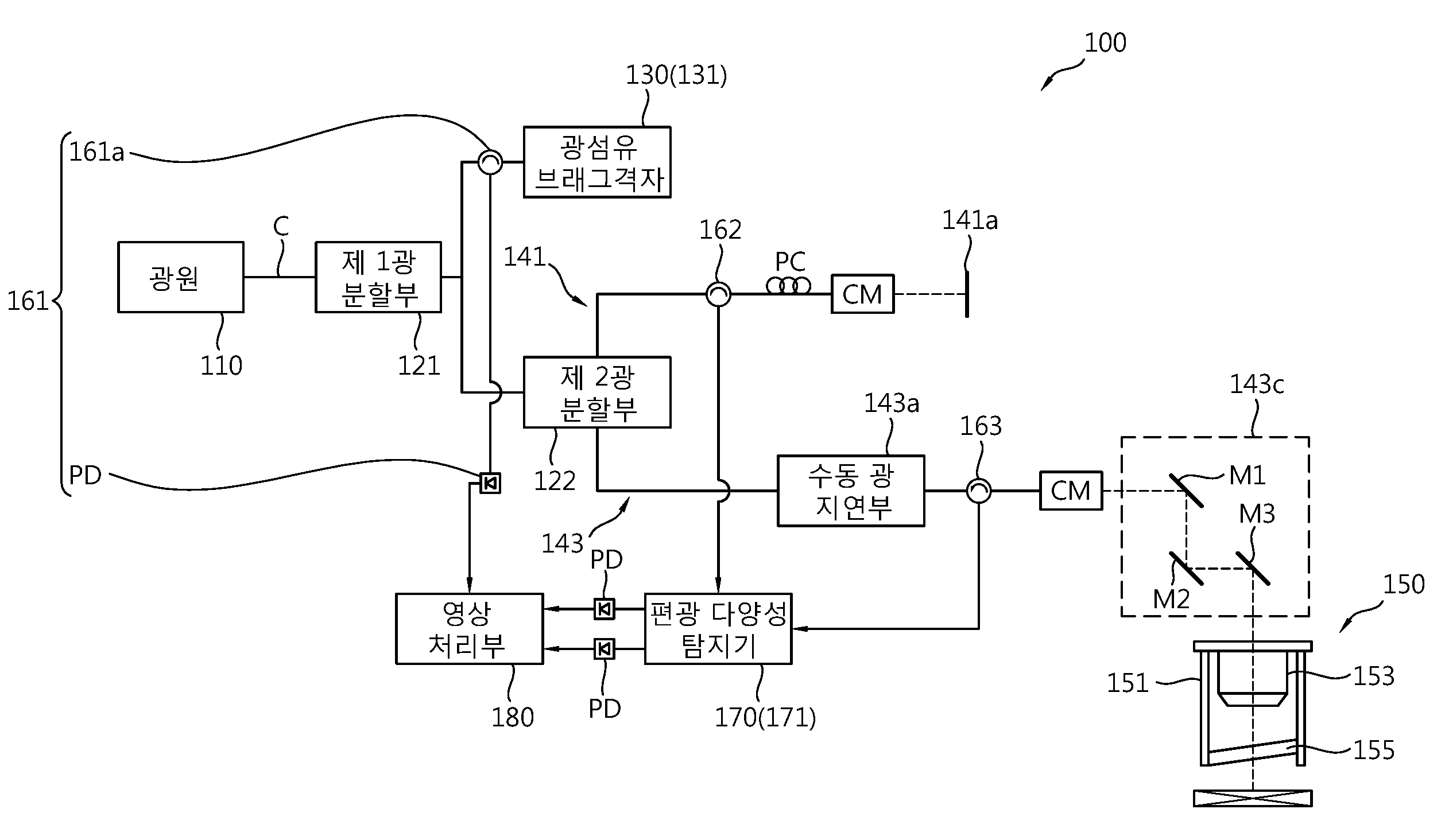
도 1은 본 실시예에 따른 편광 민감 광 간섭 단층영상장치를 나타낸 구성도이다.1 is a block diagram illustrating a polarization-sensitive optical coherent tomography imaging apparatus according to an embodiment of the present invention.
도 1에 도시된 바와 같이, 본 실시예에 따른 편광 민감 광 간섭 단층영상장치(100, 이하, 영상장치라 칭한다.)는 전립선 병변 제거 시 활용될 수 있다. 전립선은 여러 층의 결합조직성 막으로 감싸져 있고, 여러 층의 결합 조직성 막 사이에는 신경이 존재하게 된다. 여기서, 전립선 절제술과 같은 전립선의 병변 제거 시 신경의 보존은 신경을 보존하는 것이 아니라 결합 조직성 막의 제거량에 따라 보존 유무가 결정된다. 이에, 영상장치(100)는 결합조직성 막과 신경을 시각화하여 전립선 병변 제거 시 시술자의 직관적 탐지가 가능하게 할 수 있다. As shown in FIG. 1, the polarization-sensitive optical coherent
이러한 영상장치(100)는 광원(110), 광분할부(120), 트리거(Trigger) 신호 발생부(130), 간섭계(140), 탐지부(150), 신호 전달부(160), 검출부(170) 및 영상 처리부(180)를 포함한다.The
먼저, 광원(110)은 간섭성 길이(Coherence Length)가 충분히 긴 파장가변 레이저로 마련될 수 있다. 이때, 광원(110)으로부터 조사되는 광은 인체에 조사했을 때 유해하지 않은 세기를 갖도록 조사된다. 여기서, 광원(110)으로부터 조사된 광은 광섬유로 마련될 수 있는 광케이블(C)에 의해 제 1광분할부(121)로 전달된다. First, the
제 1광분할부(121)는 광원(110)으로부터 전달된 광이 트리거 신호 발생부(130)와 간섭계(140)로 분할되도록 한다. 여기서, 제 1광분할부(121)는 트리거 신호 발생부(130)로 3~7%의 광세기를 갖는 광량이 제공되도록 하고, 간섭계(140)로 93~97%의 광세기를 갖는 광량이 제공되도록 할 수 있다. 이를 위해 제 1광분할부(121)는 파이버 커플러(FC: Fiber Coupler)로 마련될 수 있으나, 광량을 분할하기 위한 구성이라면 제 1광분할부(121)의 종류는 한정하지 않는다. The first
한편, 제 1광분할부(121)로부터 분할된 3~7%의 광량은 트리거 신호 발생부(130)로 전달된다. 트리거 신호 발생부(130)는 광섬유 브래그 격자(FBG: Fiber Bragg Grating, 131)로 마련될 수 있다. 이러한 광섬유 브래그 격자(131)는 추후 데이터 수집을 위한 외부 트리거(External Trigger) 신호를 발생시키기 위한 것으로, 광섬유 브래그 격자(131)는 A-Line 마다 트리거링하도록 마련되며, 속도는 광원(110)의 스위핑속도에 대응되도록 대략 50k로 설정될 수 있다. On the other hand, the light amount of 3 to 7% divided from the first
한편, 제 1광분할부(121)와 트리거 신호 발생부(130) 사이에는 제 1신호 전달부(161)가 마련된다. 여기서, 제 1신호 전달부(161)는 트리거 신호 발생부(130)로부터의 트리거 신호가 영상 처리부(180)로 제공되도록 한다. 이때, 제 1신호 전달부(161)는 제 1광분할부(121)와 트리거 신호 발생부(130)를 연결하는 광케이블(C)에 마련되는 파이버 서큘레이터(161a)와, 파이버 서큘레이터(161a)와 영상 처리부(180)를 연결하는 광케이블(C)에 마련되는 광 검출기(PD)를 포함할 수 있다. 이에, 트리거 신호 발생부(130)로부터 발생된 트리거 신호는 제 1신호 전달부(161)를 거치며 광검출기(PD)에서 전기적 신호로 변환되어 영상 처리부(180)로 제공된다. A first
한편, 제 1광분할부(121)로부터 분할된 93~97%의 세기를 갖는 광량은 간섭계(140)로 제공된다. 여기서, 간섭계(140)로 제공되는 광은 제 2광분할부(122)에 의해 레퍼런스암(141)과 샘플암(143)으로 분할된다. 여기서, 제 2광분할부(122)는 제공되는 광 중 레퍼런스암(141)으로 15~25%의 세기를 갖는 광량이 제공되도록 하고, 샘플암(143)으로 75~85%의 세기를 갖는 광량이 제공되도록 할 수 있다. 이를 위해, 제 2광분할부(122)는 파이버 커플러로 마련될 수 있으나, 광량을 분할하기 위한 구성이라면 제 2광분할부(122)의 종류는 한정하지 않는다. On the other hand, the amount of light having the intensity of 93 to 97% divided from the first
한편, 레퍼런스암(141)으로 제공되는 광은 제 2광분할부(122)에 연결된 광케이블(C)을 통해 콜리메이터(CM)로 제공되고, 콜리메이터(CM)는 광이 레퍼런스 미러(141a)를 향해 조사되도록 하여 광이 반사되도록 할 수 있다. 여기서, 레퍼런스암(141)은 탐지부(150)를 통해 추후 검출될 전립선의 반사광과의 간섭 신호를 위한 기준광을 발생시키기 위한 것으로, 탐지부(150)로부터 전립선을 향해 조사되는 광의 침투 깊이에 따라 콜리메이터(CM)와 레퍼런스 미러(141a) 사이의 거리가 가변 가능하게 마련될 수 있다. Meanwhile, the light provided to the
그리고 레퍼런스 미러(141a)를 통해 반사된 기준광은 제 2광분할부(122)와 콜리메이터(CM) 사이에서 파이버 서큘레이터로 마련될 수 있는 제 2신호 전달부(162)를 통해 검출부(170)로 제공될 수 있다. The reference light reflected through the
한편, 샘플암(143)으로 제공되는 광은 제 2광분할부(120)에 연결된 광케이블(C)을 통해 수동 광지연부(143a)로 제공된다. The light provided to the
수동 광지연부(143a)는 제 2광분할부(122)로부터 제공되는 광을 분해하여 서로 수직하는 수평 및 수직광으로 광의 상태를 분리시킨다. 여기서, 수동 광지연부(143a)는 편광 빔 스플리터(Polarizing Beam Splitter) 및 쿼터 웨이브 플레이트(Quater Wave Plate) 중 적어도 어느 하나를 포함하도록 마련될 수 있다. 이에, 수동 광지연부(143a)에서 분해된 수평 및 수직광은 추후 탐지부(150)로 제공되고, 공기 중에서 대략 2.25mm의 광경로 차를 가지며 조사될 수 있다. The passive
한편, 수동 광지연부(143a)와 탐지부(150) 사이에는 광케이블(C)과 광 반사경로(143c)가 순차적으로 배치된다. 여기서, 수동 광지연부(143a)와 광 반사경로(143c) 사이의 광케이블(C)에는 파이버 서큘레이터로 마련될 수 있는 제 3신호 전달부(163)가 연결되어, 전립선으로부터 반사된 반사광이 검출부(170)로 제공되도록 할 수 있다. Meanwhile, an optical cable (C) and a light reflecting path (143c) are sequentially disposed between the manual light edge portion (143a) and the detecting portion (150). Here, a third
그리고 광 반사경로(143c)를 살펴보면, 수동 광지연부(143a)로부터 광케이블(C)로 제공되는 수평 및 수직광은 콜리메이터(CM)를 통해 조사되고, 적어도 하나 이상의 미러(M1, M2)를 통해 반사되어 2축 스캐닝미러(2-axis Scanning Mirror, M3)로 제공된다. 여기서, 탐지부(150)는 스캐닝미러(M3)로부터 제공되는 수평 및 수직광이 전립선으로 조사되는 조사경로와, 전립선으로부터 반사된 반사광이 광 반사경로(143c)를 통해 복귀하여 제 3신호 전달부(163)로 제공되도록 하는 반사광의 입사경로를 형성한다. The horizontal and vertical lights supplied from the passive
이러한 탐지부(150)는 탐지부(150)의 외형을 형성하는 본체(151) 내부에 렌즈(153) 및 윈도우(155)가 배치될 수 있다. 여기서, 렌즈(153)는 대물렌즈와 같은 광 집속기로 마련되며, 윈도우(155)는 표면반사가 최소화되도록 렌즈(153)의 수평방향에서 대략 5~10도 기울기를 가질 수 있다. 다만, 본 실시예서는 탐지부(150)가 적출된 조직을 촬영하기 위한 형태로 도시하고 있으나, 이는 본 실시예를 설명하기 위한 일 실시예로 체강 내부로 삽입되기 위한 프로브 형태 등으로 변형될 수 있으므로 탐지부(150)의 형태는 한정하지 않는다. The
한편, 검출부(170)는 제 2 및 제 3광분할부(122, 123)로부터의 기준광과 반사광을 수신한다. 여기서, 검출부(170)는 제 2 및 제 3광분할부(122, 123) 각각에 광케이블(C)에 의해 연결되는 편광 다양성 탐지기(PDD: Polarization Diverse Detector, 171)로 마련될 수 있다. 여기서, 편광 다양성 탐지기(171)는 기준광과 반사광으로부터 간섭신호를 발생하여 광 세기를 기반으로 하는 구조영상과, 전립선으로부터 반사된 수평광과 수직광이 광로차를 가지고 합성됨으로써 발생되는 반사광의 편광변화를 기반으로 하는 복굴절 영상이 처리부에서 출력될 수 있도록 한다. 이때, 검출부(170)와 영상 처리부(180) 사이에는 한 쌍의 광검출기(PD)가 마련되어, 검출부(170)로부터의 구조영상과 복굴절영상의 정보를 담은 신호가 전기적으로 변환되어 영상 처리부(180)로 제공되도록 한다.On the other hand, the
그리고 영상 처리부(180)는 컴퓨터와 같은 디스플레이장치로 마련될 수 있다. 여기서, 영상 처리부(180)는 검출부(170)로부터 제공되는 구조영상과 복굴절영상의 정보를 담은 신호의 전기적 신호를 기반으로 전립선의 구조영상과 복굴절영상이 각각 연산되어 디스플레이되도록 할 수 있다. 이때, 영상 처리부(180)에서 디스플레이되는 전립선의 구조영상과 복굴절영상은 전립선 병변 제거 시 시술자의 직관적 탐지가 가능하도록 한다. The
여기서, 구조영상은 전립선 주변의 그랜드 구조(Gland Structure)와 지방 정보를 제공할 수 있고, 복굴절영상은 신경절(Ganglion)에서 출발하여 방광, 직장, 음경 등으로 향하는 모든 갈래의 신경 다발에 대한 정보를 제공할 수 있다. 특히, 복굴절영상의 경우 음경으로 향하는 발기능과 관련된 음경 해면체의 신경영상 디스플레이가 가능하여 전립선 병변 제거 시 전립선 신경 보존이 용이한 이점이 있다. 또한, 영상 처리부(180)는 트리거 신호 발생부(130)로부터 제공되는 외부 트리거 신호를 기반으로 데이터 수집이 가능한 이점이 있다.Here, the structural image can provide the gland structure and the fat information around the prostate, and the birefringence image can start from the ganglion and provide information on all the nerve bundles that are directed to the bladder, rectum, penis, . In particular, in the case of birefringence images, it is possible to display the nerve image of the cavernous surface of the penis in relation to the foot function toward the penis, which is advantageous in preserving the prostate nerve when the prostate lesion is removed. In addition, the
한편, 본 실시예서는 영상장치(100)가 프로브 타입의 탐지부(150)를 포함하여 탐지부(150)가 체강 내 전립선의 영상을 획득하는 실시예를 설명하고 있다. 다만, 이는 본 실시예를 설명하기 위한 일 실시예로 본 영상장치(100)는 기존 백색광 기반의 내시경에 탑재 가능할 뿐만 아니라 현미경 형태로 마련될 수 있다. Meanwhile, the present embodiment describes an embodiment in which the
한편, 종래의 광 간섭 단층영상시스템과 본 실시예에 따른 영상장치(100)를 비교하면, 종래의 광 간섭 단층영상시스템은 빛의 편광 상태에 관계없이 굴절률이 다른 매질의 계면에서 발생한 산란광의 세기만을 측정하는 바, 매질에서 발생되는 광의 위상 변화는 고려하지 않는다. 즉, 일반적으로 수평성분과 수직성분으로 분리되지 않은 광을 전립선에 조사할 경우 복굴절에 따른 위상 지연이 발생하지만 위상 지연 정도를 분석하기 어려운 문제점이 있었다. In contrast, in the conventional optical coherent tomographic imaging system and the
그러나 본 실시예에 따른 영상장치(100)는 임상적용을 위한 유연성을 고려하며, 편광의 가변성으로 인해 광의 편광상태 유추가 어려워 광을 수직성분과 수평성분으로 분리하여 전립성으로 조사한다. 이에, 편광은 수직성분과 수평성분이 항상 유지되는 성질을 갖기 때문에 영상장치는 전립선으로 조사되는 광과 반사광의 차이를 구분하여 전립선의 관찰이 용이한 이점이 있다. However, the
한편, 이하에서는 본 실시예에 따른 편광 민감 광 간섭 단층 영상시스템을 활용한 단층영상방법에 대해 상세히 설명하도록 한다. 다만, 상술된 구성요소에 대해서는 상세한 생략을 생략하고 동일한 참조부호를 부여하도록 한다. Hereinafter, a tomographic imaging method using the polarization-sensitive optical coherent tomographic imaging system according to the present embodiment will be described in detail. However, the detailed description of the above-described components is omitted, and the same reference numerals are given thereto.
도 2는 본 실시예에 따른 편광 민감 광 간섭 단층영상방법을 나타낸 흐름도이다.2 is a flowchart illustrating a polarization-sensitive optical coherent tomography imaging method according to an embodiment of the present invention.
도 2에 도시된 바와 같이, 본 실시예에 따른 편광 민감 광 간섭 단층영상방법(이하, 영상방법이라 칭한다.)은 전립선 병변 제거 시 전립선의 구조영상과 복굴절영상이 실시간으로 디스플레이되도록 할 수 있다. As shown in FIG. 2, the polarization-sensitive optical coherent tomography (hereinafter, referred to as imaging method) according to the present embodiment can display a structural image and a birefringence image of the prostate in real time when the prostate lesion is removed.
전립선의 병변 제거는 암이 발생한 전립선 전체를 외과적으로 제거하는 전립선 절제술일 수 있으며, 최근 들어 젊은 환자들이 많아짐에 따라 암의 완전 제거뿐만 아니라 삶의 질, 성기능 및 요자제의 보존이 더욱 중요시되고 있다. 이에, 신경 보존을 위한 신경 보존 전립선 절제술이 수행되고 있으며, 신경 보존 전립선 절제술 수행 시 요실금 및 발기부전과 같은 부작용을 최소화할 수 있는 이점이 있다. Prostate lesion removal may be a prostatectomy that surgically removes the entire prostate gland. In recent years, as the number of younger patients increases, the quality of life, sexual function, have. Neurogenic preserved prostatectomy for neurological preservation has been performed, and neuro - conservative prostatectomy has the advantage of minimizing side effects such as urinary incontinence and erectile dysfunction.
전립선 절제술의 종류로는 개복, 복강경 및 로봇수술이 있고, 복강경 및 로봇수술의 경우 최소 침습 수술의 장점이 부각되며 최근 시행횟수가 증가하는 추세이다. 그러나 신경은 기본적으로 주변 조직과의 구분이 어렵고, 복강경을 기반으로 한 최소 침습 수술의 경우 시야각의 제한 및 내시경에 의존해야하기 때문에 신경의 탐지가 어려운 문제점이 있었다. Laparoscopic and robotic surgeries are the most common types of prostatectomy, and the advantages of minimally invasive surgery are increasing in laparoscopic and robotic surgery. However, the nerve is basically difficult to distinguish from the surrounding tissue, and in the case of minimally invasive surgery based on laparoscopy, there is a problem that it is difficult to detect the nerve because of the limitation of the viewing angle and the endoscope.
특히, 종래의 광 간섭 단층영상시스템의 경우, 굴절률이 다른 매질의 계면에서 발생한 산란 신호의 세기 정도에 따른 영상의 대비를 관찰하는 바, 기본적으로 관 형태의 형태학적 구조를 갖는 신경과, 림프관 및 혈관이 유사하게 관찰되어 혼란이 발생될 수 있었다. 또한, 신경은 무수히 많은 신경섬유들이 밀집해 있는 구조로, 지방조직의 지방세포 벌집형 구조와 유사하게 관찰되는 문제점이 있었다. Particularly, in the case of the conventional optical coherent tomographic imaging system, the contrast of the image according to the degree of intensity of the scatter signal generated at the interface of the medium having a different refractive index is observed. Basically, the nerve with a tubular morphology, The blood vessels were observed similarly and confusion could occur. In addition, the nerves have a structure in which a large number of nerve fibers are dense and have similar problems as observed in the adipocyte structure of adipose tissue.
그러나 본 실시예에 따른 영상장치(100)의 경우, 결합 조직성 막과 신경 모두에서 위상지연 현상으로 인한 복굴절 패턴이 관찰되며, 상호 상이한 형태로 관찰이 용이한 이점이 있다. However, in the case of the
한편, 본 실시예에 따른 영상방법에서는 영상장치를 활용한 전립선의 신경영상획득방법을 제공하도록 한다. Meanwhile, in the imaging method according to the present embodiment, a neuroimaging method of the prostate using the imaging device is provided.
먼저, 광원(110)으로부터 조사된 광은 제 1광분할부(121)에 의해 트리거 신호 발생부(130)와 간섭계(140)로 분할된다(S100). 여기서, 트리거 신호 발생부(130)로 제공된 광은 데이터 수집을 위한 외부 트리거 신호를 발생시키기 위한 것으로, 제 1신호 전달부(160)에 의해 영상 처리부(180)로 제공된다.First, the light emitted from the
한편, 간섭계(140)로 제공되는 광은 제 2광분할부(122)에 의해 레퍼런스암(141)과 샘플암(143)으로 분할된다(S200). 여기서, 레퍼런스암(141)으로 제공된 광은 기준광으로 변환되어 검출부(170)로 제공되고, 샘플암(143)으로 제공된 광은 수동 광지연부(143a)를 통해 수평 및 수직광으로 분해되어 광 반사경로(143c)와 탐지부(150)를 통해 전립선으로 조사된다. 이때, 결합조직성 막과 신경 모두에서는 복굴절에 의한 위상지연이 관찰되며, 여기서, 전립선으로부터 반사된 수평 및 수직광은 광로차를 가지며 반사광으로 변환되어 검출부(170)로 제공된다(S300). Meanwhile, the light provided to the interferometer 140 is divided into the
한편, 검출부(170)는 레퍼런스암(141)과 샘플암(143)으로부터 각각 제공되는 기준광과 반사광을 기반으로 전립선의 구조영상신호를 검출하고, 수평 및 수직광에 따른 반사광의 편광변화를 기반으로 하는 전립선의 복굴절영상신호를 검출한다. 이때, 검출된 구조영상신호와 복굴절영상신호는 각각 광검출기(PD)를 거쳐 영상 처리부(180)로 제공된다. On the other hand, the
이때, 영상 처리부(180)는 전립선의 구조영상과 복굴절영상을 디스플레이하여 전립선의 구성 정보뿐만 아니라 조직 특성 정보가 시술자에게 인지되도록 할 수 있다(S400). 또한, 영상 처리부(180)는 트리거 신호 발생부(130)로부터 제공되는 트리거 신호를 기반으로 데이터 수집이 가능할 수 있다. At this time, the
이러한 영상장치와 영상방법을 활용할 경우, 전립선의 결합 조직성 막과 신경이 상호 상이한 형태로 디스플레이된다. 즉, 결합 조직성 막의 경우 넓은 막 형태로 디스플레이되고, 신경의 경우 섬유성 형태로 디스플레이된다. 이에, 시술자는 디스플레이되는 정보에 따라 결합 조직성 막과 신경을 직관적으로 인지할 수 있고, 이를 통해 전립선 병변 제거 성공률 향상과 함께 신경의 보존이 가능하게 할 수 있다.When these imaging devices and imaging methods are used, the connective tissue membranes and nerves of the prostate gland are displayed differently. That is, in the case of the connective tissue membrane, it is displayed in a wide membrane form, and in the case of the nerve, it is displayed in the fibrous form. Thus, the practitioner can intuitively recognize the connective tissue membrane and the nerve according to the displayed information, thereby improving the success rate of prostate lesion removal and preserving the nerve.
한편, 이하에서는 본 실시예에 따른 편광 민감 광 간섭 단층 영상시스템을 활용한 실험 실시예에 대해 살펴보도록 한다. Hereinafter, an experimental example using the polarization-sensitive optical coherent tomographic imaging system according to the present embodiment will be described.
도 3은 본 실시예에 따른 편광 민감 광 간섭 단층영상시스템을 이용하여 동물모델의 전립선과 주변 조직을 촬영한 도면이다. 그리고 도 4는 본 실시예에 따른 편광 민감 광 간섭 단층영상시스템을 이용하여 환자의 전립선과 주변 조직을 촬영한 도면이다. FIG. 3 is a photograph of the prostate and surrounding tissues of an animal model using the polarization-sensitive optical coherent tomography imaging system according to the present embodiment. And FIG. 4 is a photograph of a patient's prostate and surrounding tissues using the polarization-sensitive optical coherent tomography imaging system according to the present embodiment.
도 3 및 도 4에 도시된 바와 같이, 본 실시예에 따른 편광 민감 광 간섭 단층 영상시스템(이하, 영상시스템)을 활용하여 동물모델, 예시로 쥐(Rat)의 전립선 및 주변조직과, 병변 제거 시 환자로부터 적출된 인간 전립선 및 주변조직을 관찰하였다. As shown in FIGS. 3 and 4, the polarized-sensitive optical coherent tomographic imaging system (hereinafter, referred to as an imaging system) according to the present embodiment is used to detect an animal model, for example, a prostate and surrounding tissue of a rat, The human prostate and surrounding tissues were observed from patients at the time of surgery.
도 3과 같이, 본 실시예에 따른 영상시스템을 활용함으로써 동물모델의 구조영상과 복굴절 영상을 획득할 수 있었다. 이때, 구조영상과 복굴절 영상에 의해 음경해면체 신경과, 신경 주위로 그랜드 구조및 지방 정보를 실시간으로 획득할 수 있다는 점이 확인되었다. As shown in FIG. 3, the structure and birefringence images of the animal model can be obtained by utilizing the imaging system according to the present embodiment. At this time, it was confirmed that the structure and the birefringence images can acquire the real time information of the corpus cavernosum, the grand structure and the fat around the nerve.
보다 구체적으로 도 3을 살펴보면, 도 3은 1mm 스케일의 쥐 전립선 신경 생체 이미지이다. 여기서, a 및 b는 X-Y 평면에서 정면 편광 민감 광 간섭 단층영상이고, c 내지 f는 x-z 평면에서 횡단면 편광 민감 광 간섭 단층영상이고, g는 면역형광(Immunofluorescence) 염색 이미지이다. 이때, 도 3의 D1 및 D2는 각각의 c, d와 e, f 단면의 위치를 표지하며 A1는 복굴절 섬유를 표지하고 있다. 그리고 도 3의 C1은 로컬 복굴절 영역을 표지하며, A2는 전립선 영역을 표지하고 있다. 여기서, 핵은 다피(DAPI)에 의해 착색(청색)되었고, 신경은 뉴런특이적 TuJI(neuron-specific β-Ⅲ Tublin) 항체로 착색(녹색)되었다. More specifically, referring to FIG. 3, FIG. 3 is a 1-mm-scale rat prostate gland biopsy image. Where a and b are frontal polarization sensitive optical interference tomographic images in the X-Y plane, c to f are cross-sectional polarization sensitive optical coherent tomographic images in the x-z plane, and g is an immunofluorescence stained image. In this case, D1 and D2 in FIG. 3 mark the positions of the cross sections of c, d, e, and f, respectively, and A1 labels the birefringent fiber. In FIG. 3, C1 denotes the local birefringence region, and A2 denotes the prostate region. Here, the nuclei were colored (blue) by DAPI and the nerves were colored (green) by neuron-specific β-Ⅲ Tublin antibodies.
또한, 도 4와 같이, 본 실시예에 따른 영상시스템을 활용함으로써, 인간모델의 전립선 구조영상과 복굴절 영상을 획득할 수 있었다. 이때, 발기능에 영향을 끼치는 음경해면체를 포함하는 신경혈관 다발(Neurovascular Bundle) 영역을 획득하였다.Also, as shown in FIG. 4, the prostate-structure image and the birefringence image of the human model can be obtained by utilizing the imaging system according to the present embodiment. At this time, a neurovascular bundle region including the penile corpus cavernosum that affects the foot function was obtained.
보다 구체적으로 도 4를 살펴보면, 도 4는 1mm 스케일의 인간 전립선 시편의 이미지이다. 여기서, a 및 b는 X-Y평면에서 정면 편광 민감 광 간섭 단층영상이고, c 내지 f는 X-Y평면에서 횡단면 편광 민감 광 간섭 단층영상이고, g는 면역형광 염색 이미지이다. 이때, 도 4의 D3 및 D4는 각각의 c, d와 e, f 단면의 위치를 표지하며 A3는 복굴절 섬유를, A4는 복굴절 시트 구조를 표지하고 있다. 그리고 C2는 로컬 복굴절 영역을 표지하고, A5는 전립선 주변 지방을 표지하고 있다. 여기서, 핵은 다피(DAPI)에 의해 착색(청색)되었고, 신경은 뉴런특이적 (neuron-specific) 항체로 착색(녹색)되었다. More specifically, referring to FIG. 4, FIG. 4 is an image of a 1 mm scale human prostate specimen. Where a and b are frontal polarization sensitive optical interference tomographic images in the X-Y plane, c to f are cross-sectional polarization sensitive optical interference tomographic images in the X-Y plane, and g is an immunofluorescent stained image. At this time, D3 and D4 in FIG. 4 mark the positions of the cross sections of c, d, e, and f, A3 denotes birefringent fiber, and A4 denotes birefringent sheet structure. C2 marks the local birefringence area, and A5 marks the fat surrounding the prostate. Here, nuclei were colored (blue) by DAPI and nerves were colored (green) by neuron-specific antibodies.
이 결과, 신경혈관 다발과 그 주변의 지방이 관찰되었으며, 본 실시예에 따른 영상시스템을 활용할 때 전립선의 결합 조직성 막과 신경의 실시간 이미징이 가능하여 병변 제거 시 신경의 결합조직성 막과 신경의 위치를 시술자에게 보다 정밀히 인지시킬 수 있는 이점이 있었다. As a result, a neurovascular bundle and its surrounding fat were observed. When using the imaging system according to the present embodiment, real-time imaging of the connective tissue membrane and nerve of the prostate can be performed, There is an advantage that the operator can be more precisely aware of the position of the patient.
이와 같이, 본 실시예에 따른 편광 민감 광 간섭 단층영상시스템은 결합조직성 막과 신경을 시각화하여 시술자에게 실시간 영상을 제공하는 바, 병변 제거 시 신경의 손상을 절감시킬 수 있어 수술 후 기관 기능 저하를 감소시키고 수술의 성공률을 증대시킬 수 있는 효과가 있다. As described above, the polarization-sensitive optical coherent tomographic imaging system according to the present embodiment visualizes the connective tissue membrane and the nerve to provide real-time images to the operator, which can reduce nerve damage during the removal of the lesion, And to increase the success rate of the operation.
앞에서 설명되고, 도면에 도시된 본 발명의 일 실시예는, 본 발명의 기술적 사상을 한정하는 것으로 해석되어서는 안 된다. 본 발명의 보호범위는 청구범위에 기재된 사항에 의하여만 제한되고, 본 발명의 기술분야에서 통상의 지식을 가진 자는 본 발명의 기술적 사상을 다양한 형태로 개량 변경하는 것이 가능하다. 따라서 이러한 개량 및 변경은 통상의 지식을 가진 자에게 자명한 것인 한 본 발명의 보호범위에 속하게 될 것이다.One embodiment of the invention described above and shown in the drawings should not be construed as limiting the technical idea of the present invention. The scope of protection of the present invention is limited only by the matters described in the claims, and those skilled in the art will be able to modify the technical idea of the present invention in various forms. Accordingly, such improvements and modifications will fall within the scope of the present invention as long as they are obvious to those skilled in the art.
110 : 광원
120 : 광분할부
130 : 트리거 신호 발생부
140 : 간섭계
150 : 탐지부
160 : 신호 전달부
170 : 검출부
180 : 영상 처리부
110: Light source
120:
130: Trigger signal generator
140: Interferometer
150:
160:
170:
180:
Claims (14)
상기 광원으로부터 제공되는 광을 기준광과 조사광으로 분할하는 광분할부;
상기 광분할부에 연결되어 상기 기준광의 진행 경로를 형성하는 레퍼런스암;
상기 광분할부로부터 제공되는 상기 조사광이 타겟위치인 전립선 부위로 제공되는 경로를 형성하고, 상기 조사광을 수평성분과 수직성분으로 편광시키는 광학부재를 포함하는 샘플암; 및
상기 레퍼런스암을 통과한 상기 기준광과 상기 샘플암으로부터 반사된 반사광을 수광하여 상기 전립선 부위의 영상 정보를 검출하고, 상기 기준광과 상기 반사광의 간섭신호를 이용하여 상기 전립선 부위의 구조영상 정보를 획득하며 상기 전립선 부위로부터 반사된 상기 수평성분과 상기 수직성분을 이용하여 상기 전립선 부위의 복굴절 영상 정보를 획득하는 검출부를 포함하고,
상기 샘플암으로부터 조사된 상기 수평성분과 상기 수직성분은 상기 전립선 부위로부터 반사되며, 상기 전립선 부위의 복굴절 특성에 기초하여 상기 전립선 부위의 결합 조직성 막과 신경의 조직 특성정보가 검출되도록 하고,
상기 검출부에 연결되는 영상 처리부는 상기 결합 조직성 막과 상기 신경의 복굴절영상 및 구조영상을 각각 디스플레이하며,
상기 결합조직성 막과 상기 신경은 상기 복굴절 영상에서 상호 상이한 형태로 디스플레이되되, 상기 복굴절 영상에서 상기 신경은 상기 결합조직성 막과 구별되도록 상기 결합조직성 막 상에 섬유성 형태로 디스플레이되는 것을 특징으로 하는 편광 민감 광 간섭 단층영상장치.
Light source;
A light splitting unit splitting the light provided from the light source into reference light and irradiation light;
A reference arm connected to the light splitting unit to form a path of the reference light;
A sample arm including an optical member forming a path provided to the portion of the prostate that is a target position and provided by the light dividing unit and polarizing the irradiation light to a horizontal component and a vertical component; And
Receiving the reference light having passed through the reference arm and the reflected light reflected from the sample arm to detect image information of the prostate part and acquiring structural image information of the prostate part using the interference signal of the reference light and the reflected light And a detector for obtaining birefringence image information of the prostate part using the horizontal component and the vertical component reflected from the prostate part,
Wherein the horizontal component and the vertical component irradiated from the sample arm are reflected from the prostate part and tissue characteristic information of the connective tissue membrane and the nerve of the prostate part is detected based on the birefringence characteristic of the prostate part,
Wherein the image processing unit connected to the detection unit displays the birefringent image and the structural image of the connective tissue membrane and the nerve, respectively,
Characterized in that in the birefringence image, the nerve is displayed in a fibrous form on the connective tissue membrane so as to be distinguished from the connective tissue membrane, characterized in that the connective tissue membrane and the nerve are displayed in a mutually different form in the birefringence image, Polarized light interference interference tomographic imaging device.
상기 샘플암은 상기 수평성분과 상기 수직성분이 광로차를 가지고 상기 전립선 부위로 조사되도록 하고,
상기 전립선 부위로부터 반사된 상기 수평성분과 상기 수직성분은 광로차를 가지고 각각 수광되는 것을 특징으로 하는 편광 민감 광 간섭 단층영상장치.
The method according to claim 1,
Wherein the sample arm has the horizontal component and the vertical component having an optical path difference to be irradiated to the prostate part,
Wherein the horizontal component and the vertical component reflected from the prostate part are received with an optical path difference, respectively.
상기 복굴절 영상 정보는 신경절(Ganglion)부터 방광, 직장, 및 음경으로 향하는 갈래의 신경 다발에 대한 조직 특성 정보를 포함하고,
상기 구조 영상 정보는 전립선 주변의 그랜드 구조(Gland Structure)와 지방에 대한 구조 정보를 포함하는 것을 특징으로 하는 편광 민감 광 간섭 단층영상장치.
The method according to claim 1,
The birefringence image information includes tissue characteristic information on the nerve bundles of the fork from the ganglion to the bladder, rectum, and penis,
Wherein the structure image information includes a gland structure around the prostate gland and structural information about fat.
상기 검출부는 상기 반사광으로부터 음경 해면체 신경에 대한 조직 특성 정보를 검출하는 것을 특징으로 하는 편광 민감 광 간섭 단층영상장치.
The method according to claim 1,
Wherein the detection unit detects tissue characteristic information on the penile ganglion nerve from the reflected light.
상기 조사광을 수평성분과 수직성분으로 편광시키는 단계;
상기 수평성분과 상기 수직성분을 타겟위치인 전립선 부위로 조사하는 단계; 및
상기 기준광과, 상기 전립선 부위로부터 반사된 반사광을 수광하여 상기 전립선 부위의 영상 정보를 검출하는 단계를 포함하고,
상기 검출하는 단계는 상기 기준광과 상기 반사광의 간섭신호를 이용하여 상기 전립선 부위의 구조 영상 정보를 획득하며 상기 전립선 부위로부터 반사된 상기 수평성분과 상기 수직성분을 이용하여 상기 전립선 부위의 복굴절 영상 정보를 획득하고, 상기 수평성분과 상기 수직성분이 상기 전립선 부위로부터 반사되며 상기 전립선 부위의 복굴절 특성에 기초하여 상기 전립선 부위의 결합 조직성 막과 신경의 조직 특성정보가 검출되도록 하고,
상기 검출하는 단계 이후에, 상기 결합 조직성 막과 상기 신경의 복굴절영상 및 구조영상을 각각 디스플레이하는 단계를 더 포함하고,
상기 결합조직성 막과 상기 신경은 상기 복굴절 영상에서 상호 상이한 형태로 디스플레이되되, 상기 신경은 상기 복굴절영상에서 상기 결합조직성 막과 구별되도록 상기 결합조직성 막 상에 섬유성 형태로 디스플레이되는 것을 특징으로 하는 편광 민감 광 간섭 단층영상방법.
Dividing the light provided from the light source into a reference light and an irradiation light;
Polarizing the irradiation light to a horizontal component and a vertical component;
Irradiating the horizontal component and the vertical component to a portion of the prostate that is a target position; And
Receiving the reference light and the reflected light reflected from the prostate part and detecting image information of the prostate part,
Wherein the detecting step acquires the structural image information of the prostate region using the interference signal of the reference light and the reflected light and obtains the birefringence image information of the prostate region using the horizontal component and the vertical component reflected from the prostate portion, Wherein the horizontal component and the vertical component are reflected from the portion of the prostate and tissue characteristic information of the connective tissue membrane and the nerve of the prostate portion is detected based on the birefringence characteristic of the portion of the prostate,
Further comprising displaying the birefringent image and the structural image of the connective tissue membrane and the nerve, respectively, after the detecting step,
Characterized in that said connective tissue membrane and said nerve are displayed in a mutually different form in said birefringence image, said nerve being displayed in fibrous form on said connective tissue membrane so as to be distinct from said connective tissue membrane in said birefringence image Polarized light interference coherent tomographic imaging.
상기 조사하는 단계는
상기 수평성분과 상기 수직성분이 광로차를 가지고 상기 전립선 부위로 조사되고,
상기 전립선 부위로부터 반사된 상기 수평성분과 상기 수직성분은 광로차를 가지고 각각 수광되는 것을 특징으로 하는 편광 민감 광 간섭 단층영상방법.
9. The method of claim 8,
The step of examining
Wherein the horizontal component and the vertical component are irradiated to the prostate part with an optical path difference,
Wherein the horizontal component and the vertical component reflected from the prostate part are received with an optical path difference, respectively.
상기 복굴절 영상 정보는 신경절(Ganglion)부터 방광, 직장, 및 음경으로 향하는 갈래의 신경 다발에 대한 조직 특성 정보를 포함하고,
상기 구조 영상 정보는 전립선 주변의 그랜드 구조(Gland Structure)와 지방에 대한 구조 정보를 포함하는 것을 특징으로 하는 편광 민감 광 간섭 단층영상방법.
9. The method of claim 8,
The birefringence image information includes tissue characteristic information on the nerve bundles of the fork from the ganglion to the bladder, rectum, and penis,
Wherein the structure image information includes a gland structure around the prostate gland and structural information about fat.
상기 검출하는 단계는
상기 반사광으로부터 음경 해면체 신경에 대한 조직 특성 정보를 검출하는 것을 특징으로 하는 편광 민감 광 간섭 단층영상방법.
9. The method of claim 8,
The detecting step
And tissue characteristic information on the corpus cavernosal nerve is detected from the reflected light.
Priority Applications (1)
| Application Number | Priority Date | Filing Date | Title |
|---|---|---|---|
| KR1020150167798A KR101803617B1 (en) | 2015-11-27 | 2015-11-27 | Polarization-sensitive optical coherence tomography imaging system |
Applications Claiming Priority (1)
| Application Number | Priority Date | Filing Date | Title |
|---|---|---|---|
| KR1020150167798A KR101803617B1 (en) | 2015-11-27 | 2015-11-27 | Polarization-sensitive optical coherence tomography imaging system |
Publications (2)
| Publication Number | Publication Date |
|---|---|
| KR20170062237A KR20170062237A (en) | 2017-06-07 |
| KR101803617B1 true KR101803617B1 (en) | 2017-12-28 |
Family
ID=59223764
Family Applications (1)
| Application Number | Title | Priority Date | Filing Date |
|---|---|---|---|
| KR1020150167798A Active KR101803617B1 (en) | 2015-11-27 | 2015-11-27 | Polarization-sensitive optical coherence tomography imaging system |
Country Status (1)
| Country | Link |
|---|---|
| KR (1) | KR101803617B1 (en) |
Citations (1)
| Publication number | Priority date | Publication date | Assignee | Title |
|---|---|---|---|---|
| JP2013213844A (en) * | 2003-01-24 | 2013-10-17 | General Hospital Corp | System and method for identifying tissue using low-coherence interferometry |
-
2015
- 2015-11-27 KR KR1020150167798A patent/KR101803617B1/en active Active
Patent Citations (1)
| Publication number | Priority date | Publication date | Assignee | Title |
|---|---|---|---|---|
| JP2013213844A (en) * | 2003-01-24 | 2013-10-17 | General Hospital Corp | System and method for identifying tissue using low-coherence interferometry |
Also Published As
| Publication number | Publication date |
|---|---|
| KR20170062237A (en) | 2017-06-07 |
Similar Documents
| Publication | Publication Date | Title |
|---|---|---|
| CA3012734C (en) | System and method for providing surgical guidance based on polarization-sensitive optical coherence tomography | |
| US9814392B2 (en) | Visual tracking and annotaton of clinically important anatomical landmarks for surgical interventions | |
| US8115934B2 (en) | Device and method for imaging the ear using optical coherence tomography | |
| US9693829B2 (en) | Microscopic surgery system and navigation method guided by optical coherence tomography (OCT) and automated OCT imaging field calibration | |
| JP6350517B2 (en) | Optical tomography apparatus and medical observation apparatus | |
| US20110279821A1 (en) | Optical coherence tomography with multiple sample arms | |
| US20110130652A1 (en) | Apparatus for biomedical imaging | |
| ATE556644T1 (en) | FORWARD SCANING IMAGING LIGHT FIBER PROBE | |
| WO2007038682A3 (en) | Paired angled rotation scanning probes and methods of use | |
| JP2002505890A (en) | Optical coherence tomography apparatus, fiber optic lateral scanner and "in vivo" biopsy | |
| CN116056621A (en) | Depth and contour detection of anatomical objects | |
| EP2785250A1 (en) | System and method useful for sarcomere imaging via objective-based microscopy | |
| RU2016147909A (en) | SURGICAL INSTRUMENTS PERFORMED FOR OCT DIAGNOSTICS AND RELATED WAYS | |
| CN105748040B (en) | Stereochemical structure function imaging system | |
| CN113670852A (en) | Inspection apparatus and inspection method | |
| Steuer et al. | In vivo microstructural investigation of the human tympanic membrane by endoscopic polarization-sensitive optical coherence tomography | |
| JP2022101517A (en) | Visualizing catheter irrigation using schlieren images | |
| Xia et al. | Fiber optic photoacoustic probe with ultrasonic tracking for guiding minimally invasive procedures | |
| KR101803617B1 (en) | Polarization-sensitive optical coherence tomography imaging system | |
| KR20170039784A (en) | Optical coherence tomography device for the skin diagnostic | |
| Han et al. | Intraoperative imaging based on common-path time-domain reflectometry for brain tumor surgery | |
| Zhang et al. | Real-time intraoperative full-range complex FD-OCT guided cerebral blood vessel identification and brain tumor resection in neurosurgery | |
| KR102204426B1 (en) | Image acquisition system and image acquisition method using the same | |
| US20240349997A1 (en) | Fiberscope for stereoscopic imaging and method for acquiring stereoscopic image data | |
| Lüerßen et al. | Optical characterization of vocal folds using optical coherence tomography |
Legal Events
| Date | Code | Title | Description |
|---|---|---|---|
| A201 | Request for examination | ||
| PA0109 | Patent application |
Patent event code: PA01091R01D Comment text: Patent Application Patent event date: 20151127 |
|
| PA0201 | Request for examination | ||
| E902 | Notification of reason for refusal | ||
| PE0902 | Notice of grounds for rejection |
Comment text: Notification of reason for refusal Patent event date: 20161219 Patent event code: PE09021S01D |
|
| PG1501 | Laying open of application | ||
| E90F | Notification of reason for final refusal | ||
| PE0902 | Notice of grounds for rejection |
Comment text: Final Notice of Reason for Refusal Patent event date: 20170702 Patent event code: PE09021S02D |
|
| E701 | Decision to grant or registration of patent right | ||
| PE0701 | Decision of registration |
Patent event code: PE07011S01D Comment text: Decision to Grant Registration Patent event date: 20170921 |
|
| GRNT | Written decision to grant | ||
| PR0701 | Registration of establishment |
Comment text: Registration of Establishment Patent event date: 20171124 Patent event code: PR07011E01D |
|
| PR1002 | Payment of registration fee |
Payment date: 20171124 End annual number: 3 Start annual number: 1 |
|
| PG1601 | Publication of registration | ||
| PR1001 | Payment of annual fee |
Payment date: 20201005 Start annual number: 4 End annual number: 4 |
|
| PR1001 | Payment of annual fee |
Payment date: 20210927 Start annual number: 5 End annual number: 5 |
|
| PR1001 | Payment of annual fee |
Payment date: 20220920 Start annual number: 6 End annual number: 6 |
|
| PR1001 | Payment of annual fee |
Payment date: 20230921 Start annual number: 7 End annual number: 7 |
|
| PR1001 | Payment of annual fee |