KR101796126B1 - Variable volume RF Coil for magnetic resonance imaging - Google Patents
Variable volume RF Coil for magnetic resonance imaging Download PDFInfo
- Publication number
- KR101796126B1 KR101796126B1 KR1020160067658A KR20160067658A KR101796126B1 KR 101796126 B1 KR101796126 B1 KR 101796126B1 KR 1020160067658 A KR1020160067658 A KR 1020160067658A KR 20160067658 A KR20160067658 A KR 20160067658A KR 101796126 B1 KR101796126 B1 KR 101796126B1
- Authority
- KR
- South Korea
- Prior art keywords
- coil
- movable plate
- plate
- fixed
- magnetic resonance
- Prior art date
Links
- 238000002595 magnetic resonance imaging Methods 0.000 title claims description 13
- 230000008878 coupling Effects 0.000 claims abstract description 5
- 238000010168 coupling process Methods 0.000 claims abstract description 5
- 238000005859 coupling reaction Methods 0.000 claims abstract description 5
- 230000005540 biological transmission Effects 0.000 description 3
- 230000014509 gene expression Effects 0.000 description 3
- 230000005415 magnetization Effects 0.000 description 3
- 238000005259 measurement Methods 0.000 description 3
- 239000013598 vector Substances 0.000 description 3
- 210000004556 brain Anatomy 0.000 description 2
- 229910052739 hydrogen Inorganic materials 0.000 description 2
- 239000001257 hydrogen Substances 0.000 description 2
- 239000000463 material Substances 0.000 description 2
- 238000012986 modification Methods 0.000 description 2
- 230000004048 modification Effects 0.000 description 2
- 239000004925 Acrylic resin Substances 0.000 description 1
- 229920000178 Acrylic resin Polymers 0.000 description 1
- OKTJSMMVPCPJKN-UHFFFAOYSA-N Carbon Chemical compound [C] OKTJSMMVPCPJKN-UHFFFAOYSA-N 0.000 description 1
- UFHFLCQGNIYNRP-UHFFFAOYSA-N Hydrogen Chemical compound [H][H] UFHFLCQGNIYNRP-UHFFFAOYSA-N 0.000 description 1
- DGAQECJNVWCQMB-PUAWFVPOSA-M Ilexoside XXIX Chemical compound C[C@@H]1CC[C@@]2(CC[C@@]3(C(=CC[C@H]4[C@]3(CC[C@@H]5[C@@]4(CC[C@@H](C5(C)C)OS(=O)(=O)[O-])C)C)[C@@H]2[C@]1(C)O)C)C(=O)O[C@H]6[C@@H]([C@H]([C@@H]([C@H](O6)CO)O)O)O.[Na+] DGAQECJNVWCQMB-PUAWFVPOSA-M 0.000 description 1
- OAICVXFJPJFONN-UHFFFAOYSA-N Phosphorus Chemical compound [P] OAICVXFJPJFONN-UHFFFAOYSA-N 0.000 description 1
- 229910052799 carbon Inorganic materials 0.000 description 1
- 238000001514 detection method Methods 0.000 description 1
- 230000000694 effects Effects 0.000 description 1
- 230000005284 excitation Effects 0.000 description 1
- 150000002431 hydrogen Chemical class 0.000 description 1
- 210000003127 knee Anatomy 0.000 description 1
- 210000002414 leg Anatomy 0.000 description 1
- 238000004519 manufacturing process Methods 0.000 description 1
- 238000000034 method Methods 0.000 description 1
- 230000000149 penetrating effect Effects 0.000 description 1
- 230000002093 peripheral effect Effects 0.000 description 1
- 229910052698 phosphorus Inorganic materials 0.000 description 1
- 239000011574 phosphorus Substances 0.000 description 1
- 230000008707 rearrangement Effects 0.000 description 1
- 229910052708 sodium Inorganic materials 0.000 description 1
- 239000011734 sodium Substances 0.000 description 1
Images


Classifications
-
- A—HUMAN NECESSITIES
- A61—MEDICAL OR VETERINARY SCIENCE; HYGIENE
- A61B—DIAGNOSIS; SURGERY; IDENTIFICATION
- A61B5/00—Measuring for diagnostic purposes; Identification of persons
- A61B5/05—Detecting, measuring or recording for diagnosis by means of electric currents or magnetic fields; Measuring using microwaves or radio waves
- A61B5/055—Detecting, measuring or recording for diagnosis by means of electric currents or magnetic fields; Measuring using microwaves or radio waves involving electronic [EMR] or nuclear [NMR] magnetic resonance, e.g. magnetic resonance imaging
-
- G—PHYSICS
- G01—MEASURING; TESTING
- G01R—MEASURING ELECTRIC VARIABLES; MEASURING MAGNETIC VARIABLES
- G01R33/00—Arrangements or instruments for measuring magnetic variables
- G01R33/20—Arrangements or instruments for measuring magnetic variables involving magnetic resonance
- G01R33/28—Details of apparatus provided for in groups G01R33/44 - G01R33/64
- G01R33/32—Excitation or detection systems, e.g. using radio frequency signals
- G01R33/34—Constructional details, e.g. resonators, specially adapted to MR
- G01R33/34007—Manufacture of RF coils, e.g. using printed circuit board technology; additional hardware for providing mechanical support to the RF coil assembly or to part thereof, e.g. a support for moving the coil assembly relative to the remainder of the MR system
-
- G—PHYSICS
- G01—MEASURING; TESTING
- G01R—MEASURING ELECTRIC VARIABLES; MEASURING MAGNETIC VARIABLES
- G01R33/00—Arrangements or instruments for measuring magnetic variables
- G01R33/20—Arrangements or instruments for measuring magnetic variables involving magnetic resonance
- G01R33/28—Details of apparatus provided for in groups G01R33/44 - G01R33/64
- G01R33/32—Excitation or detection systems, e.g. using radio frequency signals
- G01R33/34—Constructional details, e.g. resonators, specially adapted to MR
- G01R33/341—Constructional details, e.g. resonators, specially adapted to MR comprising surface coils
-
- G—PHYSICS
- G01—MEASURING; TESTING
- G01R—MEASURING ELECTRIC VARIABLES; MEASURING MAGNETIC VARIABLES
- G01R33/00—Arrangements or instruments for measuring magnetic variables
- G01R33/20—Arrangements or instruments for measuring magnetic variables involving magnetic resonance
- G01R33/44—Arrangements or instruments for measuring magnetic variables involving magnetic resonance using nuclear magnetic resonance [NMR]
- G01R33/48—NMR imaging systems
Landscapes
- Physics & Mathematics (AREA)
- Health & Medical Sciences (AREA)
- Life Sciences & Earth Sciences (AREA)
- Condensed Matter Physics & Semiconductors (AREA)
- General Physics & Mathematics (AREA)
- High Energy & Nuclear Physics (AREA)
- Nuclear Medicine, Radiotherapy & Molecular Imaging (AREA)
- Engineering & Computer Science (AREA)
- Molecular Biology (AREA)
- Pathology (AREA)
- Radiology & Medical Imaging (AREA)
- Biomedical Technology (AREA)
- Heart & Thoracic Surgery (AREA)
- Medical Informatics (AREA)
- Biophysics (AREA)
- Surgery (AREA)
- Animal Behavior & Ethology (AREA)
- General Health & Medical Sciences (AREA)
- Public Health (AREA)
- Veterinary Medicine (AREA)
- Magnetic Resonance Imaging Apparatus (AREA)
Abstract
방사 방향을 따라서 적어도 두 개 이상의 고정홀(h1)이 일정 회전각에 대해 회전 대칭되도록 관통 형성된 원형의 고정판(110); 상기 고정판(110)의 회전 대칭 방향과 대응되어 상기 고정홀(h1)과 체결부재(140)에 의해 조립이 이루어지는 조립홀(h2)이 관통 형성된 복수의 가동판(120); 및 상기 가동판(120) 각각에서 절곡되어 상기 고정판(110)과는 직각을 이루고 최소한 하나 이상의 표면코일 엘리먼트(200)가 구비되는 복수 개의 측판(130);을 포함한다.A circular fixing plate 110 formed so that at least two or more fixing holes h1 are rotationally symmetrical with respect to a predetermined rotation angle along the radial direction; A plurality of movable plates 120 corresponding to the rotational symmetry direction of the fixed plate 110 and having an assembly hole h2 through which the fixed hole h1 and the coupling member 140 are assembled; And a plurality of side plates 130 bent at each of the movable plates 120 and perpendicular to the fixed plate 110 and having at least one surface coil element 200.
Description
본 발명은 체적을 가변할 수 있는 자기공명영상용 RF코일에 관한 것이다.
The present invention relates to an RF coil for magnetic resonance imaging capable of varying the volume.
자기 공명 영상(magnetic resonance imaging, MRI)은 균일한 주자기장(main magnetic field) 내에서 인체 내에 존재하는 핵종(수소, 인, 나트륨, 탄소 등)의 자화벡터(magnetization vector)에 대해 고주파 RF(radiofrequency) 펄스를 인가하여 특정 핵종(수소 등)을 공명시켜 수직평면으로 자화벡터가 재정렬되면서 발생되는 자기공명 신호를 수신하여 컴퓨터를 통해 재구성하여 영상화하는 기술이다.BACKGROUND ART Magnetic resonance imaging (MRI) is a magnetic resonance imaging (MRI) technique that uses a radiofrequency (RF) magnetic field to magnetize a nuclide (hydrogen, phosphorus, sodium, carbon, etc.) in a human body in a homogeneous main magnetic field ) Pulses to resonate a specific nuclide (such as hydrogen) to receive magnetic resonance signals generated by rearrangement of magnetization vectors in a vertical plane, reconstruct them through a computer, and image them.
일반적으로 자화벡터를 공명시키기 위한 펄스 송신과 발생된 자기공명 신호의 수신은 RF코일에 의해 이루어지며, 이때 RF 코일은 자화벡터를 공명시키기 위한 RF 신호를 송신(RF 송신 모드)하는 코일과 자기공명 신호를 수신(RF 수신 모드)하는 코일이 각각 따로 마련될 수 있으며, 또는 하나의 RF코일에 의해 RF 송신 모드와 RF 수신 모드가 같이 수행될 수 있다.Generally, the pulse transmission for resonating the magnetization vector and the reception of the generated magnetic resonance signal are performed by an RF coil, where the RF coil transmits a RF signal for resonating the magnetization vector (RF transmission mode) Each of the coils for receiving a signal (RF receiving mode) may be separately provided, or an RF transmitting mode and an RF receiving mode may be performed simultaneously by one RF coil.
도 1은 종래기술에 따른 RF코일의 일례를 보여주는 도면으로, 새장형(birdcage) 코일을 보여주고 있다.FIG. 1 is a view showing an example of an RF coil according to the prior art, showing a birdcage coil.
일반적인 새장형 코일(10)은 두 개의 전도성 원형 루프인 엔드링(11)과, 두 엔드링(11)을 연결하는 복수 개의 전도성의 레그(12)로 구성된 코일 엘리먼트를 포함하며, 이러한 코일 엘리먼트(11)(12)(13)는 원통형상의 프레임(13)의 외주면에 고정된다.A typical cage-
이와 같이 새장형 코일을 포함한 일반적인 볼륨형 RF코일은 코일 엘리먼트와 함께 이를 고정 지지하기 위하여 단단한 구조의 프레임을 필수 구성으로 하며, 따라서 하나의 프레임에 하나의 코일 엘리먼트가 고정되어 부착되므로 체적이 다른 RF코일을 제작시 프레임의 낭비가 심하며, 특히 RF코일과 인체가 밀착되어 위치하지 못함에 따라서 채움인자가 저하되는 문제점이 있다.In general, a volume RF coil including a cage-type coil has a rigid frame structure in order to fix and support the coil element together with the coil element. Therefore, since one coil element is fixedly attached to one frame, There is a problem that the filling factor is lowered as the RF coil and the human body are not in close contact with each other.
채움인자(filling factor)는 RF코일 내의 측정 대상물이 차지하는 부피비로 표현되는 인자로서, 측정 대상물의 여기신호(RF 신호)와 MR 신호의 검출 효율에 영향을 주어 S/N비(signal to noise ratio)를 좌우하며, 최종적으로는 자기공명영상의 질을 결정하는 중요 인자 중의 하나이다. 채움인자는 RF코일과 조사 대상물(인체)을 최대한 밀착되게 함으로써 높일 수가 있다.The filling factor is a factor expressed as a volume ratio occupied by the measurement object in the RF coil. The filling factor affects the detection efficiency of the excitation signal (RF signal) and the MR signal of the measurement object, and the S / N ratio (signal to noise ratio) And ultimately, it is one of the important factors that determine the quality of magnetic resonance imaging. The filling factor can be increased by making the RF coil and the object to be irradiated (human body) as close as possible to each other.
따라서 채움인자를 높이기 위해서는 측정 대상의 사이즈를 고려하여 그에 적합한 크기의 RF코일을 제작하여 측정하는 것이나, 뇌, 무릎, 팔과 같은 국소부위에 대해 환자의 성별, 연령 등을 모두 고려하여 각 환자에게 맞추어 RF코일을 제작하여 사용한다는 것은 현실적으로 불가능하며, 종래에는 인체의 국소 부위에 대해 일정 사이즈 별로 제작된 RF코일을 사용하고 있는 실정이다.
Therefore, in order to increase the fill factor, it is necessary to take into account the size of the measurement object and make RF coils of suitable size, and to measure the local parts such as the brain, knee, and arm, It is practically impossible to manufacture and use RF coils in accordance with the present invention. In the past, RF coils fabricated to a predetermined size have been used for local parts of the human body.
본 발명은 이러한 종래기술의 문제점을 개선하고자 하는 것으로, 본 발명은 인체와 밀착될 수 있도록 가변 체적형의 자기공명영상용 RF코일을 제공하고자 한다.
SUMMARY OF THE INVENTION It is an object of the present invention to provide a variable volume RF coil for magnetic resonance imaging that can be closely attached to a human body.
이러한 목적을 달성하기 위한 본 발명에 따른 자기공명영상용 RF코일은, 방사 방향을 따라서 적어도 두 개 이상의 고정홀이 일정 회전각에 대해 회전 대칭되도록 관통 형성된 원형의 고정판; 상기 고정판의 회전 대칭 방향과 대응되어 상기 고정홀과 체결부재에 의해 조립이 이루어지는 조립홀이 관통 형성된 복수의 가동판; 및 상기 가동판 각각에서 절곡되어 상기 고정판과는 직각을 이루고 최소한 하나 이상의 표면코일 엘리먼트가 구비되는 복수 개의 측판;을 포함한다.According to an aspect of the present invention, there is provided an RF coil for a magnetic resonance imaging, comprising: a circular fixing plate penetrating through at least two or more fixing holes in a radial direction so as to be rotationally symmetrical with respect to a predetermined rotation angle; A plurality of movable plates corresponding to the rotational symmetry direction of the fixed plate and having an assembly hole through which the fixed hole and the coupling member are assembled; And a plurality of side plates bent at each of the movable plates and perpendicular to the fixed plate and having at least one surface coil element.
바람직하게는, 상기 가동판은 서로 나란한 상부 가동판과 하부 가동판으로 구성되어 상기 고정판은 상기 상부 가동판과 상기 하부 가동판 사이에 삽입되어 고정되는 것을 특징으로 한다.Preferably, the movable plate is composed of an upper movable plate and a lower movable plate arranged side by side, and the fixed plate is inserted and fixed between the upper movable plate and the lower movable plate.
바람직하게는, 회전 대칭 방향에 위치하는 상기 고정홀과 상기 조립홀들 사이의 간격은 등간격인 것을 특징으로 한다.
Preferably, the spacing between the fixing holes located in the rotationally symmetrical direction and the assembly holes is equally spaced.
본 발명에 따른 자기공명영상용 RF코일은, 체적을 가변할 수 있도록 복수 개로 구성된 프레임 요소 각각에 표면코일 엘리먼트가 구비됨으로써, 다양한 사이즈의 인체 부위에 대해 크기 조절이 가능하여 우수한 자기공영영상을 얻을 수 있는 효과가 있다.
In the RF coil for magnetic resonance imaging according to the present invention, since the surface coil element is provided in each of the plurality of frame elements so as to be variable in volume, the size of the human body parts of various sizes can be adjusted, There is an effect that can be.
도 1은 종래기술에 따른 RF코일의 일례를 보여주는 도면,
도 2는 본 발명에 따른 RF코일을 보여주는 사시도,
도 3은 본 발명에 따른 RF코일을 보여주는 분해 사시도,
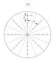
도 4는 본 발명에 따른 RF코일의 고정판의 평면도.
도 5의 (a)(b)는 본 발명에 따른 RF코일의 사용예를 보여주는 평면 구성도.1 is a view showing an example of an RF coil according to the prior art,
2 is a perspective view showing an RF coil according to the present invention,
3 is an exploded perspective view showing an RF coil according to the present invention,
4 is a plan view of a fixing plate of an RF coil according to the present invention.
5 (a) and 5 (b) are planar views showing an example of using an RF coil according to the present invention.
본 발명의 실시예에서 제시되는 특정한 구조 내지 기능적 설명들은 단지 본 발명의 개념에 따른 실시예를 설명하기 위한 목적으로 예시된 것으로, 본 발명의 개념에 따른 실시예들은 다양한 형태로 실시될 수 있다. 또한 본 명세서에 설명된 실시예들에 한정되는 것으로 해석되어서는 아니 되며, 본 발명의 사상 및 기술 범위에 포함되는 모든 변경물, 균등물 내지 대체물을 포함하는 것으로 이해되어야 한다.The specific structure or functional description presented in the embodiment of the present invention is merely illustrative for the purpose of illustrating an embodiment according to the concept of the present invention, and embodiments according to the concept of the present invention can be implemented in various forms. And should not be construed as limited to the embodiments described herein, but should be understood to include all modifications, equivalents, and alternatives falling within the spirit and scope of the invention.
한편, 본 발명에서 제1 및/또는 제2 등의 용어는 다양한 구성 요소들을 설명하는데 사용될 수 있지만, 상기 구성 요소들은 상기 용어들에 한정되지는 않는다. 상기 용어들은 하나의 구성요소를 다른 구성요소들과 구별하는 목적으로만, 예컨대 본 발명의 개념에 따른 권리 범위로부터 벗어나지 않는 범위 내에서, 제1구성요소는 제2구성요소로 명명될 수 있고, 유사하게 제2구성요소는 제1구성요소로도 명명될 수 있다.Meanwhile, in the present invention, the terms first and / or second etc. may be used to describe various components, but the components are not limited to the terms. The terms may be referred to as a second element only for the purpose of distinguishing one element from another, for example, to the extent that it does not depart from the scope of the invention in accordance with the concept of the present invention, Similarly, the second component may also be referred to as the first component.
어떠한 구성요소가 다른 구성요소에 "연결되어"있다거나 "접속되어"있다고 언급된 때에는, 그 다른 구성요소에 직접적으로 연결되어 있거나 접속되어 있을 수도 있지만, 중간에 다른 구성요소가 존재할 수도 있다고 이해되어야 할 것이다. 반면에, 어떠한 구성요소가 다른 구성요소에 "직접 연결되어"있다거나 또는 "직접 접촉되어"있다고 언급된 때에는, 중간에 다른 구성요소가 존재하지 않는 것으로 이해되어야 할 것이다. 구성요소들 간의 관계를 설명하기 위한 다른 표현들, 즉 "~사이에"와 "바로 ~사이에"또는 "~에 인접하는"과 "~에 직접 인접하는"등의 표현도 마찬가지로 해석되어야 한다.Whenever an element is referred to as being "connected" or "connected" to another element, it may be directly connected or connected to the other element, but it should be understood that other elements may be present in between something to do. On the other hand, when it is mentioned that an element is "directly connected" or "directly contacted" to another element, it should be understood that there are no other elements in between. Other expressions for describing the relationship between components, such as "between" and "between" or "adjacent to" and "directly adjacent to" should also be interpreted.
본 명세서에서 사용하는 용어는 단지 특정한 실시예를 설명하기 위해 사용된 것으로서, 본 발명을 한정하려는 의도가 아니다. 단수의 표현은 문맥상 명백하게 다르게 뜻하지 않는 한, 복수의 표현을 포함한다. 본 명세서에서 "포함한다" 또는 "가지다"등의 용어는 실시된 특징, 숫자, 단계, 동작, 구성 요소, 부분품 또는 이들을 조합한 것이 존재함을 지정하려는 것이지, 하나 또는 그 이상의 다른 특징이나 숫자, 단계, 동작, 구성 요소, 부분품 또는 이들을 조합한 것들의 존재 또는 부가 가능성을 미리 배제하지 않는 것으로 이해되어야 한다.
The terminology used herein is for the purpose of describing particular embodiments only and is not intended to be limiting of the invention. The singular expressions include plural expressions unless the context clearly dictates otherwise. It will be further understood that the terms " comprises ", or "having ", and the like in the specification are intended to specify the presence of stated features, integers, But do not preclude the presence or addition of steps, operations, elements, parts, or combinations thereof.
도 2는 본 발명의 바람직한 실시예에 따른 RF코일을 보여주는 사시도이며, 도 3은 본 발명의 바람직한 실시예에 따른 RF코일을 보여주는 분해 사시도로서, 중복되는 동일 구성에 대해서는 하나의 도면부호만을 기재하여 설명한다.FIG. 2 is a perspective view showing an RF coil according to a preferred embodiment of the present invention, FIG. 3 is an exploded perspective view showing an RF coil according to a preferred embodiment of the present invention, Explain.
이하, 본 발명의 실시예를 첨부 도면을 참고하여 상세히 설명하도록 한다.Hereinafter, embodiments of the present invention will be described in detail with reference to the accompanying drawings.
본 발명의 자기공명영상용 RF코일은, 체적을 가변할 수 있는 프레임(110)(120)(130)에 마련된 복수 개의 표면코일 엘리먼트(200)를 포함한다.The RF coil for magnetic resonance imaging of the present invention includes a plurality of
구체적으로, 도 2 및 도 3을 참고하면, 체적 가변형 프레임(110)(120)(130)은, 방사 방향을 따라서 적어도 두 개 이상의 고정홀(h1)이 일정 회전각에 대해 회전 대칭되도록 관통 형성된 원형의 고정판(110); 고정판(110)의 회전 대칭 방향과 대응되어 고정홀(h1)과 체결부재(140)에 의해 조립이 이루어지는 조립홀(h2)이 관통 형성된 복수의 가동판(120)과; 가동판(120) 각각에서 절곡되어 고정판(110)과는 직각을 이루는 복수 개의 측판(130);을 포함한다.2 and 3, the volume-
프레임(110)(120)(130)을 구성하는 고정판(110), 가동판(120) 및 측판(130)은 투명한 재질의 아크릴 수지가 사용될 수 있으며, 부도체이면서 비자성체의 특성을 갖는 범위 내에서 특정한 소재에 한정되지는 않는다.The
각 측판(130)은 적어도 하나 이상의 표면코일 엘리먼트(200)가 고정되며, 각 표면코일 엘리엄트는 케이블(미도시)이 연결된 다채널의 RF 송수신 코일로 사용될 수 있다. Each
도 4를 참고하면, 고정판(110)은 원형의 디스크 형상이며, 방사 방향(radical direction)을 따라서 복수 개의 고정홀(h1)이 일정 회전각(θ)에 대해 회전 대칭(360°/n; n은 2이상의 정수)되도록 관통 형성된다. 본 실시예에서 복수 개의 고정홀(h1)은 45°의 회전각에 대해 회전 대칭되며, 따라서 8개의 회전 대칭 방향을 갖고 각 회전 대칭 방향에 가동판(120)이 고정될 수 있다. 도 4에서 은선은 각 가동판이 위치하는 영역을 나타내고 있다.Referring to FIG. 4, the
인접한 고정홀(h1)들 사이의 간격(d)은 서로 동일하며, 가동판(120)의 조립홀(h2) 역시도 동일한 간격을 갖는다. The distance d between the adjacent fixing holes h1 is equal to each other and the mounting hole h2 of the
도 3에 예시된 것과 같이, 바람직하게는, 가동판(120)은 서로 나란한 상부 가동판(121)과 하부 가동판(122)으로 구성되어 상부 가동판(121)과 하부 가동판(122) 사이에 고정판(110)이 수평 방향으로 삽입 고정된다.3, the
고정판(110)과 가동판(120)은 고정홀(h1)과 조립홀(h2)에 삽입되는 체결부재(140)에 의해 견고히 고정될 수 있으며, 이러한 체결부재(140)는 주지의 볼트, 나사, 또는 핀 등에 의해 제공될 수 있으며, RF 송수신 신호에 영향을 주지 않도록 비전도성이고 비자성체인 재질이 사용됨이 바람직하다.
The
도 5의 (a)(b)는 본 발명에 따른 RF코일의 사용예를 보여주는 평면 구성도로서, 고정판(110)에 하나의 가동판(120)만이 조립된 것을 예시하고 있으며, 조립홀(h2) 중에 검정색으로 채워진 것은 체결부재가 조립된 것을 나타낸다.5 (a) and 5 (b) are plan views showing an example of using the RF coil according to the present invention, in which only one
도 5에 예시된 것과 같이, 고정판(110)에 대해 방사 방향으로 가동판(120)은 전후 위치 이동하여 고정될 수 있으며, 따라서 가동판(120)의 조립 위치에 따라서 RF코일의 체적에 대한 조정이 이루어질 수 있다.5, the
이와 같이 구성된 본 발명의 자기공명영상용 RF코일은 환자의 뇌에 대한 자기공명영상에 효과적일 수 있으며, 환자의 두부 사이즈에 따라서 가동판의 위치를 조정하여 채움인자를 크게 하여 우수한 자기공명영상을 얻을 수 있다.
The RF coil for magnetic resonance imaging according to the present invention can be effectively applied to a magnetic resonance imaging of a patient's brain. By adjusting the position of a movable plate according to a head size of a patient, Can be obtained.
이상에서 설명한 본 발명은 전술한 실시예 및 첨부된 도면에 의해 한정되는 것이 아니고, 본 발명의 기술적 사상을 벗어나지 않는 범위 내에서 여러 가지 치환, 변형 및 변경이 가능함은 본 발명이 속하는 기술분야에서 통상의 지식을 가진 자에게 명백할 것이다.
It will be apparent to those skilled in the art that various modifications and variations can be made in the present invention without departing from the spirit or scope of the inventions. It will be apparent to those of ordinary skill in the art.
110 : 고정판 120 : 가동판
121 : 상부 가동판 122 : 하부 가동판
130 : 측판 140 : 체결부재
200 : 표면코일 엘리먼트 h1 : 고정홀
h2 : 조립홀110: fixed plate 120: movable plate
121: upper movable plate 122: lower movable plate
130: side plate 140: fastening member
200: surface coil element h1: fixed hole
h2: Assembly hole
Claims (3)
상기 고정판의 회전 대칭 방향과 대응되어 상기 고정홀과 체결부재에 의해 조립이 이루어지는 조립홀이 관통 형성된 복수의 가동판; 및
상기 가동판 각각에서 절곡되어 상기 고정판과는 직각을 이루고 최소한 하나 이상의 표면코일 엘리먼트가 구비되는 복수 개의 측판;을 포함하되,
상기 고정홀과 상기 조립홀에 삽입되는 체결부재의 조립 위치에 따라서 상기 가동판은 상기 고정판에 대해 방사 방향으로 고정 위치가 가변될 수 있는 자기공명영상용 RF코일.A circular fixing plate penetratingly formed so that at least two or more fixing holes are rotationally symmetrical with respect to a predetermined rotation angle along a radial direction;
A plurality of movable plates corresponding to the rotational symmetry direction of the fixed plate and having an assembly hole through which the fixed hole and the coupling member are assembled; And
And a plurality of side plates bent at each of the movable plates, the side plates being perpendicular to the fixed plate and having at least one surface coil element,
Wherein the movable plate is capable of varying a fixed position in a radial direction with respect to the fixed plate depending on an assembling position of the fixing hole and the coupling member inserted into the assembly hole.
Priority Applications (1)
| Application Number | Priority Date | Filing Date | Title |
|---|---|---|---|
| KR1020160067658A KR101796126B1 (en) | 2016-05-31 | 2016-05-31 | Variable volume RF Coil for magnetic resonance imaging |
Applications Claiming Priority (1)
| Application Number | Priority Date | Filing Date | Title |
|---|---|---|---|
| KR1020160067658A KR101796126B1 (en) | 2016-05-31 | 2016-05-31 | Variable volume RF Coil for magnetic resonance imaging |
Publications (1)
| Publication Number | Publication Date |
|---|---|
| KR101796126B1 true KR101796126B1 (en) | 2017-11-13 |
Family
ID=60385971
Family Applications (1)
| Application Number | Title | Priority Date | Filing Date |
|---|---|---|---|
| KR1020160067658A KR101796126B1 (en) | 2016-05-31 | 2016-05-31 | Variable volume RF Coil for magnetic resonance imaging |
Country Status (1)
| Country | Link |
|---|---|
| KR (1) | KR101796126B1 (en) |
Cited By (2)
| Publication number | Priority date | Publication date | Assignee | Title |
|---|---|---|---|---|
| CN114264991A (en) * | 2021-11-26 | 2022-04-01 | 深圳市联影高端医疗装备创新研究院 | Mammary gland receiving coil assembly and magnetic resonance imaging equipment |
| CN115317146A (en) * | 2022-09-14 | 2022-11-11 | 杭州佳量医疗科技有限公司 | Coil arrangement for magnetic resonance imaging and magnetic resonance imaging-based system |
Citations (2)
| Publication number | Priority date | Publication date | Assignee | Title |
|---|---|---|---|---|
| US20070103153A1 (en) | 2005-11-08 | 2007-05-10 | Uwe Bottcher | Volume coil for a magnetic resonance tomography apparatus |
| JP5771354B2 (en) | 2009-11-10 | 2015-08-26 | 株式会社日立メディコ | Receiving coil device for magnetic resonance imaging apparatus and magnetic resonance imaging apparatus using the same |
-
2016
- 2016-05-31 KR KR1020160067658A patent/KR101796126B1/en active IP Right Grant
Patent Citations (2)
| Publication number | Priority date | Publication date | Assignee | Title |
|---|---|---|---|---|
| US20070103153A1 (en) | 2005-11-08 | 2007-05-10 | Uwe Bottcher | Volume coil for a magnetic resonance tomography apparatus |
| JP5771354B2 (en) | 2009-11-10 | 2015-08-26 | 株式会社日立メディコ | Receiving coil device for magnetic resonance imaging apparatus and magnetic resonance imaging apparatus using the same |
Cited By (3)
| Publication number | Priority date | Publication date | Assignee | Title |
|---|---|---|---|---|
| CN114264991A (en) * | 2021-11-26 | 2022-04-01 | 深圳市联影高端医疗装备创新研究院 | Mammary gland receiving coil assembly and magnetic resonance imaging equipment |
| CN114264991B (en) * | 2021-11-26 | 2024-05-24 | 深圳市联影高端医疗装备创新研究院 | Mammary gland receiving coil assembly and magnetic resonance imaging equipment |
| CN115317146A (en) * | 2022-09-14 | 2022-11-11 | 杭州佳量医疗科技有限公司 | Coil arrangement for magnetic resonance imaging and magnetic resonance imaging-based system |
Similar Documents
| Publication | Publication Date | Title |
|---|---|---|
| JP5209842B2 (en) | Multi-winding element RF coil array for multi-channel MRI and method of manufacturing an RF coil assembly | |
| JP4733177B2 (en) | Magnetic resonance imaging apparatus and RF coil for magnetic resonance imaging apparatus | |
| US20190154776A1 (en) | Rf coil assembly | |
| US20080197845A1 (en) | Magnetic structure for mri machines and mri machine particularly for orthopedic of rheumatologic applications | |
| JP2009517133A (en) | Cavity resonators for magnetic resonance systems | |
| CN103869269B (en) | Phased array RF coil modules and the MR imaging apparatus for using the module | |
| KR102237827B1 (en) | Radio frequency coil comprising dielectric structure and Magnetic resonance imaging system comprising the radio frequency coil | |
| US7466130B1 (en) | Phased array shoulder coil | |
| KR101796126B1 (en) | Variable volume RF Coil for magnetic resonance imaging | |
| JP5611902B2 (en) | Module MRI phased array antenna | |
| US10698045B2 (en) | Magnetic resonance coil arrangement with adaptive coil spacing layer | |
| JP2006314796A (en) | Three concentric coil array | |
| CN102809735A (en) | Design of shoulder coil having upper components and/or dependent on selection of supporting elements | |
| KR102290276B1 (en) | Radio frequency surface coil and Magnetic resonance imaging system comprising the same | |
| JP5771354B2 (en) | Receiving coil device for magnetic resonance imaging apparatus and magnetic resonance imaging apparatus using the same | |
| KR101856376B1 (en) | Multi- channel Helmholtz coil for magnetic resonance imaging and magnetic resonance imaging system | |
| KR101856375B1 (en) | Dipole antenna for magnetic resonance imaging, radio frequency coil assembly, and magnetic resonance imaging system | |
| KR102564686B1 (en) | RF coil for MRI to measure the molar concentration of a specific nuclide | |
| KR102216541B1 (en) | RF surface coil and magnetic resonance apparatus employing the same | |
| JP5258968B2 (en) | Magnetic resonance measuring device | |
| KR20220072471A (en) | RF coil device with variable shape for MRI | |
| US11125841B2 (en) | Radio frequency coil and magnetic resonance imaging system comprising the same | |
| KR102537482B1 (en) | Wireless RF surface coil with adjustable size | |
| US10481224B2 (en) | RF surface coil unit and magnetic resonance imaging system comprising same | |
| KR102644728B1 (en) | Inductively coupled micro-stripline RF coil for MRI |
Legal Events
| Date | Code | Title | Description |
|---|---|---|---|
| PA0109 | Patent application |
Patent event code: PA01091R01D Comment text: Patent Application Patent event date: 20160531 |
|
| PA0201 | Request for examination | ||
| PE0902 | Notice of grounds for rejection |
Comment text: Notification of reason for refusal Patent event date: 20170605 Patent event code: PE09021S01D |
|
| E701 | Decision to grant or registration of patent right | ||
| PE0701 | Decision of registration |
Patent event code: PE07011S01D Comment text: Decision to Grant Registration Patent event date: 20170919 |
|
| GRNT | Written decision to grant | ||
| PR0701 | Registration of establishment |
Comment text: Registration of Establishment Patent event date: 20171103 Patent event code: PR07011E01D |
|
| PR1002 | Payment of registration fee |
Payment date: 20171103 End annual number: 3 Start annual number: 1 |
|
| PG1601 | Publication of registration | ||
| PR1001 | Payment of annual fee |
Payment date: 20201012 Start annual number: 4 End annual number: 4 |
|
| PR1001 | Payment of annual fee |
Payment date: 20211104 Start annual number: 5 End annual number: 5 |
|
| PR1001 | Payment of annual fee |
Payment date: 20221102 Start annual number: 6 End annual number: 6 |
|
| PR1001 | Payment of annual fee |
Payment date: 20231023 Start annual number: 7 End annual number: 7 |
|
| PR1001 | Payment of annual fee |
Payment date: 20241023 Start annual number: 8 End annual number: 8 |