KR101792501B1 - Method and apparatus for feature-based stereo matching - Google Patents
Method and apparatus for feature-based stereo matching Download PDFInfo
- Publication number
- KR101792501B1 KR101792501B1 KR1020110023400A KR20110023400A KR101792501B1 KR 101792501 B1 KR101792501 B1 KR 101792501B1 KR 1020110023400 A KR1020110023400 A KR 1020110023400A KR 20110023400 A KR20110023400 A KR 20110023400A KR 101792501 B1 KR101792501 B1 KR 101792501B1
- Authority
- KR
- South Korea
- Prior art keywords
- image
- reference image
- points
- feature
- tracking
- Prior art date
- Legal status (The legal status is an assumption and is not a legal conclusion. Google has not performed a legal analysis and makes no representation as to the accuracy of the status listed.)
- Expired - Fee Related
Links
Images


Classifications
-
- H—ELECTRICITY
- H04—ELECTRIC COMMUNICATION TECHNIQUE
- H04N—PICTORIAL COMMUNICATION, e.g. TELEVISION
- H04N13/00—Stereoscopic video systems; Multi-view video systems; Details thereof
- H04N13/20—Image signal generators
- H04N13/271—Image signal generators wherein the generated image signals comprise depth maps or disparity maps
-
- G—PHYSICS
- G06—COMPUTING OR CALCULATING; COUNTING
- G06T—IMAGE DATA PROCESSING OR GENERATION, IN GENERAL
- G06T7/00—Image analysis
- G06T7/50—Depth or shape recovery
- G06T7/55—Depth or shape recovery from multiple images
- G06T7/593—Depth or shape recovery from multiple images from stereo images
-
- G—PHYSICS
- G06—COMPUTING OR CALCULATING; COUNTING
- G06T—IMAGE DATA PROCESSING OR GENERATION, IN GENERAL
- G06T7/00—Image analysis
- G06T7/50—Depth or shape recovery
- G06T7/55—Depth or shape recovery from multiple images
- G06T7/579—Depth or shape recovery from multiple images from motion
-
- H—ELECTRICITY
- H04—ELECTRIC COMMUNICATION TECHNIQUE
- H04N—PICTORIAL COMMUNICATION, e.g. TELEVISION
- H04N13/00—Stereoscopic video systems; Multi-view video systems; Details thereof
- H04N13/20—Image signal generators
- H04N13/204—Image signal generators using stereoscopic image cameras
- H04N13/207—Image signal generators using stereoscopic image cameras using a single 2D image sensor
- H04N13/218—Image signal generators using stereoscopic image cameras using a single 2D image sensor using spatial multiplexing
-
- H—ELECTRICITY
- H04—ELECTRIC COMMUNICATION TECHNIQUE
- H04N—PICTORIAL COMMUNICATION, e.g. TELEVISION
- H04N13/00—Stereoscopic video systems; Multi-view video systems; Details thereof
- H04N13/20—Image signal generators
- H04N13/275—Image signal generators from 3D object models, e.g. computer-generated stereoscopic image signals
-
- H—ELECTRICITY
- H04—ELECTRIC COMMUNICATION TECHNIQUE
- H04N—PICTORIAL COMMUNICATION, e.g. TELEVISION
- H04N13/00—Stereoscopic video systems; Multi-view video systems; Details thereof
- H04N13/20—Image signal generators
- H04N13/282—Image signal generators for generating image signals corresponding to three or more geometrical viewpoints, e.g. multi-view systems
-
- G—PHYSICS
- G06—COMPUTING OR CALCULATING; COUNTING
- G06T—IMAGE DATA PROCESSING OR GENERATION, IN GENERAL
- G06T2207/00—Indexing scheme for image analysis or image enhancement
- G06T2207/10—Image acquisition modality
- G06T2207/10016—Video; Image sequence
- G06T2207/10021—Stereoscopic video; Stereoscopic image sequence
-
- G—PHYSICS
- G06—COMPUTING OR CALCULATING; COUNTING
- G06T—IMAGE DATA PROCESSING OR GENERATION, IN GENERAL
- G06T2207/00—Indexing scheme for image analysis or image enhancement
- G06T2207/30—Subject of image; Context of image processing
- G06T2207/30196—Human being; Person
Landscapes
- Engineering & Computer Science (AREA)
- Computer Vision & Pattern Recognition (AREA)
- Physics & Mathematics (AREA)
- General Physics & Mathematics (AREA)
- Theoretical Computer Science (AREA)
- Multimedia (AREA)
- Signal Processing (AREA)
- Length Measuring Devices By Optical Means (AREA)
- Image Analysis (AREA)
Abstract
본 발명에 따른 특징기반의 스테레오 매칭 방법 및 장치가 개시된다. 본 발명에 따른 스테레오 매칭 방법은 적어도 두 개의 카메라로 동일한 시각에 다른 관점에서 촬영된 레퍼런스 영상과 적어도 하나의 비교 영상에 대하여, 컴퓨터 장치를 이용하여 스테레오 매칭하는 방법으로, 상기 레퍼런스 영상과 상기 적어도 하나의 비교 영상을 수집하는 단계, 상기 레퍼런스 영상에서 특징점들을 추출하는 단계, 광 흐름 기법을 이용하여, 상기 적어도 하나의 비교 영상에서 각각 상기 각 특징점들에 대응되는 점들을 추적하는 대응점 추적단계 및 상기 대응점 추적 결과에 따라 깊이 맵을 생성하는 단계를 포함하여 구성된다. 따라서, 캘리브레이션의 필요 없이, 광흐름 기법을 이용한 특징점 추적을 통하여 양안 영상의 색감이나 밝기에 민감하지 않은 안정적인 고속의 깊이 맵을 생성할 수 있으며, 복수의 카메라의 상대적 위치나 배치 간격과 같은 최소한의 사전 정보를 이용하여 추적 윈도우의 모양이나 크기를 조정함으로써 특징점 추적 속도와 정확도가 개선된 스테레오 매칭을 수행할 수 있다. A feature-based stereo matching method and apparatus according to the present invention is disclosed. A stereo matching method according to the present invention is a stereo matching method for a reference image and at least one comparison image photographed from different viewpoints at the same time with at least two cameras using a computer device, A corresponding point tracking step of tracking points corresponding to each of the minutiae points in the at least one comparison image using an optical flow technique; And generating a depth map according to the tracking result. Therefore, it is possible to generate a stable high-speed depth map that is insensitive to the color or brightness of the binocular image through the feature point tracking using the optical flow technique without the need for calibration, By adjusting the shape and size of the tracking window using the dictionary information, stereo matching can be performed with improved tracking speed and accuracy.
Description
본 발명은 좌측 및 우측 영상의 픽셀간 양안차를 생성하는 스테레오 매칭방법 및 장치에 관한 것이며, 좀더 상세하게는 캘리브레이션을 요구하지 않으면서 고속의 깊이 맵을 형성할 수 있는 특징 기반의 스테레오 매칭 방법 및 장치에 관한 것이다.The present invention relates to a stereo matching method and apparatus for generating a binocular difference between pixels of left and right images, and more particularly, to a feature-based stereo matching method capable of forming a high-speed depth map without requiring calibration, ≪ / RTI >
일반적으로 스테레오 매칭은 인간이 두 개의 눈을 가지고 사물의 거리를 인지하는 방법과 동일한 방식을 이용하여 서로 다른 관점에서 얻어진 두 영상 사이의 대응점간의 변이를 추정하여 정확하고 신뢰성 있는 변이맵(disparity map)을 얻는 것을 말한다. In general, stereo matching is an accurate and reliable disparity map by estimating the variation between the corresponding points of two images obtained from different viewpoints using the same method as that of a human having two eyes and recognizing the distance of objects. .
더 나아가서, 변이맵을 이용하여 깊이 맵(Depth map)을 만들어 냄으로써 깊이감이 있는 3차원 영상을 복원할 수 있다. 이러한 스테레오 매칭 방법은 크게 영역기반(Area-based) 방법과 특징기반(Feature-based) 방법으로 나눌 수 있는데, 특징 기반 방법은 영역기반 방법이 갖는 여러 가지 제약사항에서 비교적 자유로울 수 있으며, 더욱 정확하고 강인한 깊이 맵을 생성할 수는 있다. 그러나 상대적으로 성긴 깊이 맵(sparse depth map)을 생성할 수 밖에 없기 때문에 응용에 따라 다르겠지만 일반적으로는 영상 전체에 걸쳐 촘촘한 깊이 맵(dense depth map)을 생성할 수 있는 영역 기반 방법을 선호한다. Furthermore, by creating a depth map using a variation map, a three-dimensional image with a sense of depth can be restored. This stereo matching method can be roughly classified into area-based method and feature-based method. Feature-based method can be relatively free from various constraints of area-based method, You can create robust depth maps. However, since it is necessary to generate a relatively coarse depth map, it is generally preferable to use a region-based method capable of generating a dense depth map across the entire image, depending on the application.
그러나 영역 기반 방법은 항상 에피폴라 라인(epi-polar)을 일치시키는 캘리브레이션 과정이 필요하며, 영상의 모든 영역에 대해서 깊이값을 계산하기 때문에 특징기반 방법보다 연산 시간이 오래 걸린다. 또한 다음과 같은 조건들을 만족한다는 가정하에 스테레오 매칭이 수행된다는 단점이 있다.However, the area-based method always requires a calibration process that matches the epi-polar, and it requires a longer computation time than the feature-based method because it calculates depth values for all areas of the image. In addition, stereo matching is performed on the assumption that the following conditions are satisfied.
- 광원이 무한대의 거리에서 점 광원일 것.- The light source should be a point light source at an infinite distance.
- 장면안의 물체가 램버시안 표면일 것.- The object in the scene should be a lambertian surface.
- 양안의 색감이나 특징들의 왜곡이 비교적 적을 것.- The color of the eyes and distortion of the features should be relatively small.
스테레오 매칭 외에도 TOF(Time of Flight) 카메라나 IR(infrared ray) 레이저 등을 이용한 액티브 센싱(Active sensing) 기술을 이용하여 사용자의 제스처를 인식하는 기술들도 있다. 그러나 TOF카메라는 너무 고가인데다가 레이저는 사용자의 눈에 부담을 줄 수 있고, 두 가지 모두 얇은 형태의 소형으로 제작하기도 힘들어서 고 정밀의 가공기술이 필요하다는 단점이 있다.In addition to stereo matching, there are technologies for recognizing a user's gesture using active sensing technology using a TOF (Time of Flight) camera or an IR (infrared ray) laser. However, the TOF camera is too expensive, and the laser can put a burden on the user's eyes, and it is difficult to manufacture both of them in the form of a thin shape.
상기와 같은 문제점을 해결하기 위한 본 발명의 목적은, 소형의 저가 장비를 활용하면서도 캘리브레이션이 필요없는 특징기반의 스테레오 매칭 방법을 제공하는데 있다.SUMMARY OF THE INVENTION It is an object of the present invention to solve the above problems and provide a feature-based stereo matching method that does not require calibration while utilizing a small-sized low-cost equipment.
상기와 같은 문제점을 해결하기 위한 본 발명의 목적은, 소형이면서도 저가의 장비를 활용하면서도 캘리브레이션이 필요 없는 특징기반의 스테레오 매칭 장치를 제공하는데 있다.An object of the present invention is to provide a feature-based stereo matching apparatus that does not require calibration while utilizing a small yet inexpensive device.
상기 목적을 달성하기 위한 본 발명의 일 측면은, 다른 관점에서 촬영된 레퍼런스 영상과 적어도 하나의 비교 영상에 대하여, 컴퓨터 장치를 이용하여 스테레오 매칭하는 방법으로, 상기 레퍼런스 영상과 상기 적어도 하나의 비교 영상을 수집하는 단계, 상기 레퍼런스 영상에서 특징점들을 추출하는 단계, 광 흐름 기법을 이용하여, 상기 적어도 하나의 각 비교 영상에서 상기 각 특징점들에 대응되는 점들을 추적하는 대응점 추적단계 및 상기 대응점 추적 결과에 따라 깊이 맵을 생성하는 단계를 포함하는 스테레오 매칭 방법을 제공한다.According to an aspect of the present invention, there is provided a method of stereo matching a reference image and at least one comparison image photographed from different viewpoints using a computer device, the method comprising: A corresponding point tracking step of tracking points corresponding to the respective minutiae points in the at least one comparison image using an optical flow technique; And generating a depth map according to the depth map.
여기서, 상기 레퍼런스 영상과 상기 적어도 하나의 비교 영상 각각에 대하여, 본래의 영상보다 해상도를 일정 단계별로 낮추어서, 다양한 해상도 레벨을 갖는 영상을 생성하되, 본래 영상보다 해상도가 낮은 적어도 하나의 영상을 생성하는 단계를 더 포함하고, 상기 특징점 추출 및 대응점 추적은 해상도가 가장 낮은 레퍼런스 영상과 이에 대응하는 비교 영상에서부터 시작하여, 본래의 해상도를 갖는 레퍼런스 영상과 이에 대응하는 비교 영상에 대해서 최종적으로 수행하는 것을 특징으로 한다.In this case, for each of the reference image and the at least one comparison image, at least one image having a resolution lower than that of the original image is generated by generating an image having various resolution levels by lowering the resolution of the reference image and the at least one comparison image, The feature point extraction and correspondence point tracking are finally performed on the reference image having the original resolution and the corresponding comparison image starting from the reference image having the lowest resolution and the corresponding comparison image, .
여기서, 상기 레퍼런스 영상에서 특징점을 추출하는 방법은, 상기 레퍼런스 영상의 각 위치에서 그레디언트 행렬 G의 고유값을 계산하고, 그 결과로 산출된 두 개의 고유값 중 작은 고유값에 대하여 내림차순으로 각 해당하는 점들을 나열함으로써, 일정순위 내의 점들을 추출하는 것을 특징으로 한다.Here, the method for extracting feature points from the reference image may include calculating an eigenvalue of a gradient matrix G at each position of the reference image, calculating a corresponding eigenvalue of the gradient matrix G in descending order, And extracting points in a certain order by arranging the points.
여기서, 상기 광흐름 기법에 뉴턴-랩슨(Newton-Raphson) 방법을 적용함으로써, 여러 번 반복하여 근접한 대응점을 찾는 것을 특징으로 한다.Here, by applying the Newton-Raphson method to the optical flow technique, it is characterized by repeatedly repeating several times to find a corresponding point.
여기서, 상기 대응점 추적단계는, 상기 레퍼런스 영상에서 상기 특징점에 대응하는 점들을 추적하기 위한, 특징점 추적 윈도우를 구성하는 단계를 포함하고, 상기 특징점 추적 윈도우는 미리 제공된 정보에 따라서, 윈도우의 크기, 모양 및 중심점의 위치가 변경되는 것을 특징으로 한다.The step of tracking the corresponding point may include constructing a feature point tracking window for tracking points corresponding to the feature point in the reference image, wherein the feature point tracking window includes a size, a shape And the position of the center point is changed.
여기서, 상기 미리 제공된 정보는 상기 적어도 두 대의 카메라간의 상대적 위치, 배치 간격 중 적어도 하나를 포함하는 것을 특징으로 한다.Here, the previously provided information includes at least one of a relative position and an arrangement interval between the at least two cameras.
여기서, 상기 레퍼런스 영상과 상기 적어도 하나의 비교 영상의 전경과 배경을 분리시키는 단계를 더 포함하고, 상기 레퍼런스 영상과 상기 적어도 하나의 비교 영상은 각각 적외선 조명을 이용하여 촬영되고, 상기 특징점 추출과 상기 대응점 추적은 각각 상기 레퍼런스 영상의 전경 및 상기 적어도 하나의 비교 영상의 전경에 대해서 수행되는 것을 특징으로 한다.Wherein the reference image and the at least one comparison image are each photographed using infrared illumination, and the feature point extraction and the at least one comparison image are separated from each other, And the corresponding point tracking is performed on the foreground of the reference image and the foreground of the at least one comparison image, respectively.
여기서, 상기 각 영상으로부터 전경과 배경을 분리시키는 방법은 상기 각 영상에서 일정한 밝기 이상의 영역을 전경으로 분리하거나 또는 영상의 일정한 비율을 전경으로 분리하는 것을 특징으로 한다.Here, the method for separating foreground and background from each image is characterized in separating an area having a predetermined brightness or more in each of the images into foreground or separating a certain ratio of the image into foreground.
여기서, 상기 레퍼런스 영상 및 적어도 하나의 비교 영상은 적어도 2개의 카메라로 동일한 시각에 다른 관점에서 촬영된 것을 특징으로 한다.Here, the reference image and the at least one comparison image are photographed by at least two cameras at the same time from different viewpoints.
상기의 목적을 달성하기 위한 본 발명의 다른 측면은, 다른 관점에서 촬영된 레퍼런스 영상과 적어도 하나의 비교영상에 대하여, 컴퓨터 장치를 이용하여 스테레오 매칭하는 방법으로, 상기 레퍼런스 영상과 상기 적어도 하나의 비교영상을 수집하는 단계, 상기 레퍼런스 및 상기 적어도 하나의 비교 영상 각각에 대하여, 본래의 영상보다 해상도를 일정 단계별로 낮추어서, 다양한 해상도 레벨을 갖는 영상을 생성하되, 본래 영상보다 해상도가 낮은 적어도 하나의 영상을 생성하는 단계, 상기 레퍼런스 영상에서 제1특징점들을 추출하는 단계, 광 흐름 기법을 이용하여, 상기 적어도 하나의 각 비교 영상에서, 상기 각 제1 특징점들에 대응되는 제 1 대응점들을 추적하는 단계, 상기 적어도 하나의 각 비교 영상에서 제 2 특징점들을 추출하는 단계, 광 흐름 기법을 이용하여, 상기 레퍼런스 영상에 대하여, 상기 각 제 2 특징점들에 대응되는 제 2 대응점들을 추적하는 단계 및 상기 제 1 및 제 2 대응점 추적 결과를 합성하여 깊이 맵을 생성하는 단계를 포함하고, 상기 제1 및 제2 특징점 추출과 상기 제1 및 제2 대응점 추적은 해상도가 가장 낮은 영상들에 대해서부터 시작하여, 본래의 해상도를 갖는 영상들에 대해서 최종적으로 수행하는 것을 특징으로 하는 스테레오 매칭 방법을 제공한다.According to another aspect of the present invention, there is provided a method of stereo matching a reference image and at least one comparison image photographed from different viewpoints using a computer device, the method comprising: The image processing method according to claim 1, further comprising the steps of: generating an image having a different resolution level by lowering the resolution of each of the reference and the at least one comparison image by a predetermined step, Extracting first feature points from the reference image, tracking first corresponding points corresponding to the first feature points in the at least one comparison image using an optical flow technique, Extracting second feature points from the at least one respective comparison image, Tracking the second corresponding points corresponding to the second feature points with respect to the reference image and generating a depth map by synthesizing the first and second corresponding point tracking results, Wherein the first and second feature point extraction and the first and second corresponding point tracking are finally performed on images having the original resolution starting from the images having the lowest resolution. .
여기서, 상기 제1 및 제2 특징점을 추출하는 방법은, 상기 레퍼런스 영상 및 적어도 하나의 비교 영상의 각 위치에서 그레디언트 행렬 G의 고유값을 계산하고, 그 결과로 산출된 두 개의 고유값 중 작은 고유값에 대하여 내림차순으로 각 해당하는 점들을 나열함으로써, 일정순위 내의 점들을 추출하는 것을 특징으로 한다.Here, the method for extracting the first and second feature points may include calculating an eigenvalue of the gradient matrix G at each position of the reference image and the at least one comparison image, And extracting points in a predetermined order by arranging corresponding points in descending order with respect to the values.
상기 다른 목적을 달성하기 위한 본 발명은 다른 관점에서 촬영된 레퍼런스 영상과 적어도 하나의 비교 영상을 이용하여, 스테레오 매칭하는 장치로, 상기 레퍼런스 영상과 상기 적어도 하나의 비교 영상을 수집하는 영상 수집부, 상기 레퍼런스 영상에서 특징점들을 추출하되, 상기 레퍼런스 영상의 각 위치의 그레디언트 행렬의 고유값을 계산하고, 그 결과로 산출된 두 개의 고유값 중 작은 고유값에 대하여 내림차순으로 각 해당하는 점들을 나열함으로써, 일정순위 내의 점들을 특징점으로 추출하는 특징점 추출부, 광 흐름 기법을 이용하여, 상기 적어도 하나의 비교영상에서 각각 상기 각 특징점들에 대응되는 점들을 추적하는 대응점 추적부 및 상기 대응점들 추적 결과를 이용하여 깊이 맵을 생성하는 깊이 맵 생성부를 포함하는 것을 특징으로 하는 스테레오 매칭 장치를 제공한다.According to another aspect of the present invention, there is provided an apparatus for stereo matching using a reference image and at least one comparison image photographed from different viewpoints, the apparatus comprising: an image collection unit for collecting the reference image and the at least one comparison image; The feature point extraction unit extracts feature points from the reference image, calculates eigenvalues of a gradient matrix at each position of the reference image, and lists corresponding points in descending order of small eigenvalues among the two eigenvalues calculated as a result, A feature point extracting unit for extracting points within a predetermined rank as feature points, an association point tracking unit for tracking points corresponding to the respective feature points in the at least one comparison image using an optical flow technique, And a depth map generating unit for generating a depth map It provides a stereo matching unit.
여기서, 상기 레퍼런스 영상과 적어도 하나의 비교영상 각각에 대하여, 본래의 영상보다 해상도를 일정 단계별로 낮추어서, 다양한 해상도 레벨을 갖는 영상을 생성하되, 본래 영상보다 해상도가 낮은 적어도 하나의 영상을 생성하는 해상도 조정부를 더 포함하고, 상기 특징점 추출 및 대응점 추적은 해상도가 가장 낮은 레퍼런스 영상과 이에 대응하는 비교영상에서부터 시작하여, 본래의 해상도를 갖는 레퍼런스 영상과 이에 대응하는 비교 영상에 대해서 최종적으로 수행하는 것을 특징으로 한다.Here, the resolution of each of the reference image and the at least one comparison image is lower than that of the original image by a predetermined step, thereby generating an image having various resolution levels, and at least one image having a resolution lower than that of the original image The feature point extraction and correspondence point tracking are finally performed on the reference image having the original resolution and the corresponding comparison image starting from the reference image having the lowest resolution and the corresponding comparison image, .
여기서, 상기 대응점 추적부는 특징점 추적 윈도우를 이용하여 상기 레퍼런스 영상에서 상기 특징점에 대응하는 점들을 추적하고, 상기 특징점 추적 윈도우는 상기 적어도 두 대의 카메라간의 상대적 위치, 배치 간격 중 적어도 하나의 정보를 기초로, 윈도우의 크기, 모양 및 중심점의 위치가 변경되는 것을 특징으로 한다.Here, the corresponding point tracking unit tracks points corresponding to the feature points in the reference image using a feature point tracking window, and the feature point tracking window is based on at least one of a relative position and an arrangement interval between the at least two cameras , The size of the window, the shape, and the position of the center point are changed.
여기서, 상기 레퍼런스 영상과 상기 적어도 하나의 영상에서 각각 전경과 배경을 분리하되, 상기 각 영상의 일정한 밝기 이상의 영역 또는 일정한 비율을 전경으로 분리하는 전경/배경 분리부를 더 포함하고, 상기 레퍼런스 영상과 상기 적어도 하나의 비교 영상은 각각 적외선 조명을 이용하여 촬영되고, 상기 특징점 추출과 상기 광흐름 기법을 이용한 대응점 추적은 각각 상기 레퍼런스 영상 및 상기 적어도 하나의 비교 영상의 전경에 대해서 수행되는 것을 특징으로 한다.The apparatus of claim 1, further comprising a foreground / background separator that separates foreground and background from the reference image and the at least one image, respectively, The at least one comparison image is photographed using infrared illumination, and the feature point extraction and the corresponding point tracking using the optical flow technique are performed on the foreground of the reference image and the foreground of the at least one comparison image, respectively.
여기서, 상기 적어도 하나의 비교 영상에서 제 2 특징점들을 추출하는 제 2 특징점 추출부, 광 흐름 기법을 이용하여, 상기 레퍼런스 영상에서, 상기 각 제 2 특징점들에 대응되는 점을 추출하는 제 2 대응점 추적부를 더 포함하고, 상기 깊이 맵 생성부는 상기 대응점 추적 결과에 상기 제2 대응점 추적결과를 합성하여 상기 깊이 맵을 생성하는 것을 특징으로 한다.A second feature point extractor for extracting second feature points from the at least one comparison image; a second correspondence point extractor for extracting points corresponding to the second feature points from the reference image using an optical flow technique; Wherein the depth map generator generates the depth map by combining the second corresponding point tracking result with the corresponding point tracking result.
여기서, 상기 레퍼런스 영상 및 적어도 하나의 비교 영상은 적어도 2개의 카메라로 동일한 시각에 다른 관점에서 촬영된 것을 특징으로 한다.Here, the reference image and the at least one comparison image are photographed by at least two cameras at the same time from different viewpoints.
여기서, 상기 스테레오 매칭 장치는 박막 형태로 제작되어 컴퓨터의 LCD 측에 내장하거나 부착하는 것을 특징으로 한다.Here, the stereo matching device is formed in a thin film form and is built in or attached to the LCD side of a computer.
상기와 같은 본 발명에 따른 특징기반의 스테레오 매칭 방법 및 장치를 이용하면, 캘리브레이션의 필요 없이, 광흐름 기법을 이용한 특징점 추적을 통하여 양안 영상의 색감이나 밝기에 민감하지 않은 안정적인 고속의 깊이 맵을 생성할 수 있다. 또한 복수의 카메라의 상대적 위치나 배치 간격과 같은 최소한의 사전 정보를 이용하여 추적 윈도우의 모양이나 크기를 조정함으로써 특징점 추적 속도와 정확도가 개선된 스테레오 매칭을 수행할 수 있다. Using the feature-based stereo matching method and apparatus according to the present invention, stable high-speed depth maps that are not sensitive to the color or brightness of a binocular image are generated through feature point tracking using an optical flow technique without the need for calibration can do. In addition, stereo matching can be performed with improved feature point tracking speed and accuracy by adjusting the shape and size of the tracking window by using a minimum amount of advance information such as the relative position and arrangement interval of the plurality of cameras.
도 1은 본 발명의 일 실시예에 따른 특징 기반의 스테레오 매칭 과정을 보여주는 시퀀스 차트이다.
도2 는 본 발명의 일 실시예에 따른 다양한 해상도를 갖도록 조정된 영상을 예시하는 개념도이다.
도 3은 본 발명의 일 실시예에 따른 특징 기반의 스테레오 매칭 방법을 이용하여 깊이 맵을 생성한 결과의 일예를 보여주는 개념도이다.
도 4a 및 4b 본 발명의 일 실시예에 따른 특징 기반의 스테레오 매칭 방법을 이용한 사용자와 컴퓨터간의 인터랙션의 일 예를 보여주는 개념도이다.
도 5a 및 5b는 본 발명의 일 실시예에 따른 특징 기반의 스테레오 매칭 방법을 이용하여 깊이맵을 생성한 결과의 다른 예를 보여주는 개념도이다.
도 6은 본 발명의 일 실시예에 따른 특징 기반의 스테레오 매칭 방법을 이용한 사용자와 컴퓨터간의 인터랙션 용용 예를 보여주는 개념도이다.
도 7은 본 발명의 일 실시예에 따른 특징점 추적 윈도우의 구성을 예시하는 개념도이다.
도 8은 역광이 있는 배경의 영향을 받은 영상과 이에 대한 스테레오 매칭결과의 일 예를 보여주는 개념도이다.
도 9는 본 발명의 일 실시예에 따른 적외선 조명이 부착된 카메라를 예시하는 개념도이다.
도 10은 본 발명의 다른 실시예에 따른 대칭방법을 적용한 특징기반의 스테레오 매칭 과정을 보여주는 시퀀스 챠트이다.
도 11는 본 발명의 일 실시예에 따른 특징 기반의 스테레오 매칭 장치를 보여주는 개념도이다.
도 12는 본 발명의 다른 실시예에 따른 대칭방법을 적용한 특징기반의 스테레오 매칭 장치를 보여주는 개념도이다.
도 13은 본 발명의 스테레오 매칭 장치를 박막형태로 제작하여 컴퓨터에 내장한 예를 보여주는 개념도이다.1 is a sequence chart illustrating feature-based stereo matching according to an embodiment of the present invention.
2 is a conceptual diagram illustrating an image adjusted to have various resolutions according to an embodiment of the present invention.
3 is a conceptual diagram illustrating an example of a result of generating a depth map using a feature-based stereo matching method according to an embodiment of the present invention.
4A and 4B are conceptual diagrams illustrating an example of interaction between a user and a computer using a feature-based stereo matching method according to an embodiment of the present invention.
5A and 5B are conceptual diagrams showing another example of a result of generating a depth map using a feature-based stereo matching method according to an embodiment of the present invention.
FIG. 6 is a conceptual diagram illustrating an example of an interaction between a user and a computer using a feature-based stereo matching method according to an embodiment of the present invention.
7 is a conceptual diagram illustrating a configuration of a feature point tracking window according to an embodiment of the present invention.
8 is a conceptual diagram showing an example of a stereo-matching result and a video image affected by a backlit background.
9 is a conceptual diagram illustrating a camera with infrared light according to an embodiment of the present invention.
FIG. 10 is a sequence chart illustrating a feature-based stereo matching process using a symmetry method according to another embodiment of the present invention.
11 is a conceptual diagram illustrating a feature-based stereo matching apparatus according to an embodiment of the present invention.
FIG. 12 is a conceptual diagram showing a feature-based stereo matching apparatus to which a symmetric method according to another embodiment of the present invention is applied.
13 is a conceptual diagram showing an example in which the stereo matching device of the present invention is manufactured in a thin film form and incorporated into a computer.
본 발명은 다양한 변경을 가할 수 있고 여러 가지 실시예를 가질 수 있는 바, 특정 실시예들을 도면에 예시하고 상세한 설명에 상세하게 설명하고자 한다. 그러나, 이는 본 발명을 특정한 실시 형태에 대해 한정하려는 것이 아니며, 본 발명의 사상 및 기술 범위에 포함되는 모든 변경, 균등물 내지 대체물을 포함하는 것으로 이해되어야 한다. 각 도면을 설명하면서 유사한 참조부호를 유사한 구성요소에 대해 사용하였다. While the invention is susceptible to various modifications and alternative forms, specific embodiments thereof are shown by way of example in the drawings and will herein be described in detail. It should be understood, however, that the invention is not intended to be limited to the particular embodiments, but includes all modifications, equivalents, and alternatives falling within the spirit and scope of the invention. Like reference numerals are used for like elements in describing each drawing.
제1, 제2, A, B 등의 용어는 다양한 구성요소들을 설명하는데 사용될 수 있지만, 상기 구성요소들은 상기 용어들에 의해 한정되어서는 안 된다. 상기 용어들은 하나의 구성요소를 다른 구성요소로부터 구별하는 목적으로만 사용된다. 예를 들어, 본 발명의 권리 범위를 벗어나지 않으면서 제1 구성요소는 제2 구성요소로 명명될 수 있고, 유사하게 제2 구성요소도 제1 구성요소로 명명될 수 있다. 및/또는 이라는 용어는 복수의 관련된 기재된 항목들의 조합 또는 복수의 관련된 기재된 항목들 중의 어느 항목을 포함한다. The terms first, second, A, B, etc. may be used to describe various elements, but the elements should not be limited by the terms. The terms are used only for the purpose of distinguishing one component from another. For example, without departing from the scope of the present invention, the first component may be referred to as a second component, and similarly, the second component may also be referred to as a first component. And / or < / RTI > includes any combination of a plurality of related listed items or any of a plurality of related listed items.
어떤 구성요소가 다른 구성요소에 "연결되어" 있다거나 "접속되어" 있다고 언급된 때에는, 그 다른 구성요소에 직접적으로 연결되어 있거나 또는 접속되어 있을 수도 있지만, 중간에 다른 구성요소가 존재할 수도 있다고 이해되어야 할 것이다. 반면에, 어떤 구성요소가 다른 구성요소에 "직접 연결되어" 있다거나 "직접 접속되어" 있다고 언급된 때에는, 중간에 다른 구성요소가 존재하지 않는 것으로 이해되어야 할 것이다. It is to be understood that when an element is referred to as being "connected" or "connected" to another element, it may be directly connected or connected to the other element, . On the other hand, when an element is referred to as being "directly connected" or "directly connected" to another element, it should be understood that there are no other elements in between.
본 출원에서 사용한 용어는 단지 특정한 실시예를 설명하기 위해 사용된 것으로, 본 발명을 한정하려는 의도가 아니다. 단수의 표현은 문맥상 명백하게 다르게 뜻하지 않는 한, 복수의 표현을 포함한다. 본 출원에서, "포함하다" 또는 "가지다" 등의 용어는 명세서상에 기재된 특징, 숫자, 단계, 동작, 구성요소, 부품 또는 이들을 조합한 것이 존재함을 지정하려는 것이지, 하나 또는 그 이상의 다른 특징들이나 숫자, 단계, 동작, 구성요소, 부품 또는 이들을 조합한 것들의 존재 또는 부가 가능성을 미리 배제하지 않는 것으로 이해되어야 한다.The terminology used in this application is used only to describe a specific embodiment and is not intended to limit the invention. The singular expressions include plural expressions unless the context clearly dictates otherwise. In the present application, the terms "comprises" or "having" and the like are used to specify that there is a feature, a number, a step, an operation, an element, a component or a combination thereof described in the specification, But do not preclude the presence or addition of one or more other features, integers, steps, operations, elements, components, or combinations thereof.
다르게 정의되지 않는 한, 기술적이거나 과학적인 용어를 포함해서 여기서 사용되는 모든 용어들은 본 발명이 속하는 기술 분야에서 통상의 지식을 가진 자에 의해 일반적으로 이해되는 것과 동일한 의미를 가지고 있다. 일반적으로 사용되는 사전에 정의되어 있는 것과 같은 용어들은 관련 기술의 문맥 상 가지는 의미와 일치하는 의미를 가지는 것으로 해석되어야 하며, 본 출원에서 명백하게 정의하지 않는 한, 이상적이거나 과도하게 형식적인 의미로 해석되지 않는다.
Unless defined otherwise, all terms used herein, including technical or scientific terms, have the same meaning as commonly understood by one of ordinary skill in the art to which this invention belongs. Terms such as those defined in commonly used dictionaries are to be interpreted as having a meaning consistent with the contextual meaning of the related art and are to be interpreted as either ideal or overly formal in the sense of the present application Do not.
이하, 본 발명에 따른 특징기반의 스테레오 매칭 방법과 장치가 개시된다. 본 발명의 스테레오 매칭 방법은 에피폴라 라인(epipolar line)을 구하지 않는다. 따라서 캘리브레이션을 수행하기 위하여 여러 가지 복잡한 소프트웨어와 하드웨어 조절을 수행하지 않아도 된다. 또한 양안에서 촬영된 영상의 색감이나 밝기 값이 완전히 일치할 필요가 없다. 특징 기반의 방법이기 때문에 성긴 깊이 맵을 생성하나 여러 응용에 충분히 사용될 수 있을만큼의 깊이 맵이 생성되며, 그 속도 또한 실시간으로 이용할 수 있을 정도의 속도로 계산된다.A feature-based stereo matching method and apparatus in accordance with the present invention are disclosed below. The stereo matching method of the present invention does not find an epipolar line. Therefore, it is not necessary to perform various complicated software and hardware adjustments to perform the calibration. Also, the color and brightness values of the images taken in both eyes need not be completely matched. Since it is a feature-based method, it creates a coarse depth map, but generates a depth map enough to be used for various applications, and the speed is also calculated at a rate that can be used in real time.
이러한 캘리브레이션이 필요없는 고속의 스테레오 매칭을 위하여 본 발명은 크게 다음과 같은 두 가지 단계로 이루어진다.For high-speed stereo matching that does not require such calibration, the present invention mainly comprises the following two steps.
1, 영상의 매 프레임에 대하여 추적이 잘 될 수 있는 특징점을 레퍼런스 영상에서 찾는다.1, a feature point that can be tracked with respect to each frame of the image is searched in the reference image.
2. 광흐름(Optical flow) 기법을 이용하여 비교 영상에서 앞서 찾은 특징점에 대응되는 위치를 추적한다.
2. Track the position corresponding to the feature point found in the comparative image using the optical flow technique.
일반적으로 광흐름 기법은 시간차를 갖고 생성된 영상에서 이웃한 프레임간의 영상의 이동 방향을 검출하기 위해서 사용되어왔다. 예를 들어 카메라가 좌측에서 우측으로 움직이는 경우, 촬영된 영상은 우측에서 좌측으로 이동하게 되며, 광흐름 기법을 이용하여 이것을 감지한 뒤, 카메라가 어느 방향으로 움직이고 있는 지 추정할 수 있다. 또한 광흐름 기법이 스테레오 매칭 방법에 사용되어 온 경우도 있지만, 대부분 좌, 우측 각 영상에 시간차 광흐름을 적용한 뒤, 이로부터 얻어지는 정보를 이용하여 스테레오 매칭을 수행하였다.In general, the optical flow technique has been used to detect the moving direction of an image between neighboring frames in a generated image with a time difference. For example, when the camera moves from left to right, the photographed image moves from right to left, and it can be detected using the light flow technique, and then it can be estimated which direction the camera is moving. In some cases, optical flow techniques have been used in stereo matching methods. However, stereo matching has been performed using information obtained from the time difference optical flow in most left and right images.
그러나 본 발명에서는 시간적 순서를 갖는 프레임에 광흐름 기법을 적용하던 것을 공간적 순서에 적용하였다. 기준 영상인 레퍼런스 영상과 레퍼런스 영상에 대비되는 비교 영상들은 동일한 시간에 다른 관점에서 촬영된 영상이며, 이러한 영상들은 상당부분 동일한 물체를 담고 있다. 이것은 물체를 정지시킨 상태에서 하나의 카메라를 이용하여 서로 다른 위치에서 두 번 촬영한 것과 다르지 않다. 또한 물체가 정지되어 있기 때문에 양쪽 영상에 촬영된 물체는 서로간의 모양 변화가 없는 강체(rigid body)로 가정할 수 있다. 따라서 단지 두 영상에서는 대부분의 위치 이동(Translation)과 약간의 아핀변환(Affine transform)이 일어났다고 볼 수 있다. 이제 남은 일은 레퍼런스 영상에서 좋은 특징점을 찾아서 그것을 비교 영상에서 잘 추적하는 일이며, 이는 고속의 스테레오 매칭을 위하여 본 발명에서 제안하는 특징이다.
However, in the present invention, the application of the optical flow technique to the frames having temporal order is applied to the spatial order. The reference image, which is the reference image, and the comparison image, which is compared with the reference image, are images taken from different viewpoints at the same time, and these images contain much the same object. This is not different from shooting two times at different positions using a single camera with the object stopped. Also, since the object is stationary, the objects photographed on both images can be assumed to be a rigid body with no change in shape between each other. Therefore, it can be seen that most of the two images have a translation and a little affine transform. What remains to do is to find good feature points in the reference image and track it well in the comparison image, which is a feature proposed in the present invention for high speed stereo matching.
이하, 본 발명에 따른 바람직한 실시예를 첨부된 도면을 참조하여 상세하게 설명한다.Hereinafter, preferred embodiments according to the present invention will be described in detail with reference to the accompanying drawings.
도 1은 본 발명의 일 실시예에 따른 특징 기반의 스테레오 매칭 과정을 보여주는 시퀀스 차트이다.1 is a sequence chart illustrating feature-based stereo matching according to an embodiment of the present invention.
도 1을 참조하면 본 발명의 일 실시예에 따른 특징 기반의 스테레오 매칭 방법은 영상수집 단계(S110), 영상의 전경/배경 분리단계(S120), 영상의 해상도 조절단계(S130), 특징점 추출 단계(S140), 대응점 추적단계(S150), 깊이 맵 생성단계(S160)를 포함하여 구성될 수 있다.Referring to FIG. 1, a feature-based stereo matching method according to an exemplary embodiment of the present invention includes an image collecting step S110, a foreground / background separating step S120, an image resolution adjusting step S130, (S140), a corresponding point tracking step (S150), and a depth map generating step (S160).
도 1을 참조하면, 본 발명의 일 실시예에 따른 특징 기반의 스테레오 매칭의 각 단계는 다음과 같이 설명될 수 있다.Referring to FIG. 1, each step of feature-based stereo matching according to an embodiment of the present invention can be described as follows.
영상수집 단계(S110)는 복수의 카메라를 이용하여 촬영된 복수개의 영상을 컴퓨터를 이용하여 수집하는 단계이다. 본 발명의 실시예에서는 적어도 두 대의 카메라를 통하여 수집된 적어도 두 개의 영상 중 하나의 레퍼런스 영상과 적어도 하나의 참조 영상을 이용한다. 레퍼런스 영상은 특징점을 추출하기 위한 기준이 되는 영상이며, 참조영상은 레퍼런스 영상에서 추출한 특징점에 대응되는 점을 찾기위한 영상이다.The image collection step S110 is a step of collecting a plurality of images photographed using a plurality of cameras using a computer. In an embodiment of the present invention, at least one reference image and at least one reference image are used from at least two images collected through at least two cameras. The reference image is a reference image for extracting a feature point, and the reference image is an image for searching for a point corresponding to a feature point extracted from a reference image.
영상의 전경/배경 분리단계(S120)는 수집된 복수개의 각 영상에서 전경과 배경을 분리하여 전경에 대해서만 특징점을 추적할 수 있도록함으로써, 역광이나 배경 등에 민감한 영상을 좀 더 정확하게 분석하기 위함이다. 따라서 본 단계는 상황에 따라서 선택적으로 적용할 수 있을 것이다.The foreground / background separating step (S120) of the image is for analyzing the images more sensitive to backlight or background, by separating the foreground and background from each of the plurality of collected images so that the feature points can be tracked only for foreground. Therefore, this step can be selectively applied depending on the situation.
영상의 해상도 조절단계(S130)는 레퍼런스 영상과 비교 영상 각각에 대하여, 본래의 영상보다 해상도를 낮춘 단계별 저해상도 버전의 영상을 생성하는 단계이다. 이는 특징점 추출시 해상도가 가장 낮은 버전의 영상에서부터 수행하도록 하여, 영상간의 변이차가 낮은 상태에서부터 스테레오 매칭을 시작할 수 있도록함으로써 좀 더 정확한 매칭 결과를 얻기 위함이다. 이부분에 대한 좀 더 상세한 설명은 후술하기로 한다. The step of adjusting the resolution of the image (S130) is a step of generating a low-resolution version of the image for each of the reference image and the comparison image, the resolution of which is lower than that of the original image. This is to obtain a more accurate matching result by allowing the stereo matching to be started from a state in which the difference between the images is low, by performing the decoding from the version of the image having the lowest resolution in extracting the feature point. A more detailed description of this part will be given later.
특징점 추출단계(S140)는 레퍼런스 영상에서 추적이 잘될수 있는 특징점을 찾는 단계이다. 레퍼런스 영상은 미리 지정이 될 수도 있고 본 단계에서 임의로 지정하게 할 수도 있을 것이다.The feature point extracting step (S140) is a step of finding feature points that can be tracked in the reference image. The reference image may be designated in advance or may be arbitrarily designated in this step.
대응점 추적단계(S150)는 광흐름(Optical Flow)기법을 이용하여, 레퍼런스 영상 이외의 영상들을 비교영상으로 하여, 앞서 찾은 특징점에 대응하는 점의 위치를 비교영상에서 추적하는 단계이다. 광흐름 기법을 이용하여 특징점을 추적하는 방법은 이하 좀 더 상세한 실시예에서 설명하기로 한다.The correspondent point tracking step (S150) uses the optical flow technique to use images other than the reference image as comparison images, and to track the positions of points corresponding to the previously found feature points in the comparison image. A method for tracking feature points using an optical flow technique will be described in more detail below.
깊이 맵 생성단계(S160)는 특징점에 대응하는 점의 추적 결과에 따라 깊이 맵을 구성하여 3차원 영상을 복원하기 위한 단계로서, 본 발명에 따른 방법은 캘리브레이션을 수행하지 않음으로써 고속의 깊이 맵을 형성할 수 있는 장점이 있다.
The depth map generation step S160 is a step for reconstructing a 3D image by constructing a depth map according to a tracking result of a point corresponding to a minutia point. The method according to the present invention does not perform calibration, There is an advantage that it can be formed.
이하 본 발명에 따른 광흐름 기법을 이용한 스테레오 매칭방법에 대하여 좀 더 자세한 실시예를 통하여 설명하기로 한다. Hereinafter, the stereo matching method using the optical flow technique according to the present invention will be described in more detail with reference to the embodiments.
간단한 실시예를 위하여 평행 카메라 모델을 이용했다고 가정할때, 광흐름 기법에 의하여 추적된 점의 양쪽 영상에서의 거리가 길다면 이것은 상대적으로 카메라와 가까운 곳에 있는 점이며, 이것이 짧다면 상대적으로 먼 곳에 있는 점이다. 그러나 일반적인 광흐름 기법이 항상 정확한 추적을 보장하는 것이 아니다. 예를 들어 카메라를 좌, 우로 놓고 촬영한 경우, 광흐름 기법을 이용시 수직으로 구성된 물체에서는 평행한 방향으로 추적이 진행되기 보다는 위아래 방향으로 추적이 진행되는 경우가 많다. 이러한 경우 광흐름에 사용되는 윈도우의 크기를 너비, 높이 비대칭으로 구성하거나 어느 정도 좌, 우 측으로만 추적되도록 구성하는 방법도 있을 것이다. 그러나 본 발명에서는 더욱 바람직한 실시예를 위하여 아주 강인하고 정확한 방법으로 양안 영상에서의 특징을 추적해 나가는 과정을 설명하고자 한다.Assuming that a parallel camera model is used for a simple example, if the distance from both images of the point traced by the light flow technique is long, this is a point relatively close to the camera, and if it is short, It is a point. However, a common optical flow technique does not always guarantee accurate tracking. For example, when the camera is shot left and right, when the light flow technique is used, tracking is performed in the vertical direction rather than in the parallel direction. In this case, the size of the window used for the optical flow may be configured as asymmetrical in width and height, or may be configured to be tracked only to the left or right side to some extent. However, in the present invention, a description will be given of a process of tracing features in the binocular image in a very robust and accurate manner for a more preferred embodiment.
일반적인 영역기반 스테레오 매칭 방법은 영상의 밝기값을 그대로 사용한다. 이것은 양안 영상의 색감이나 밝기값이 거의 일치해야 하며, 두 영상 사이의 왜곡이 거의 없다는 것을 가정하고 있다. 그러나 동일한 모델의 카메라를 이용하더라도 각 카메라의 특성상 색감이 조금씩 다를 수 있으며 완전히 색감이나 밝기값을 동기화 시키는 데에는 많은 노력이 필요하다. 본 발명에서는 절대적인 밝기값이 아닌, 특징점 주변에서의 그레디언트 분포를 사용하기 때문에 양안에 밝기나 색상의 차이가 조금 나더라도 큰 문제없이 동작할 수 있다.A general region-based stereo matching method uses the brightness value of the image as it is. This assumes that the color and brightness values of the binocular image should be approximately the same and there is little distortion between the two images. However, even if the camera of the same model is used, the color feeling may be slightly different due to the characteristics of each camera, and it takes much effort to completely synchronize the color and brightness values. In the present invention, since the gradient distribution in the vicinity of the feature point is used instead of the absolute brightness value, even if there is a slight difference in brightness or color between both eyes, it can be operated without a great problem.
먼저 I와 J를 각각 앞에서 얘기한 레퍼런스 영상과 비교 영상이라고 하고, ![]()
![]()
![]()
![]()
![]()
![]()
![]()
![]()
![]()
![]()
![]()
![]()
![]()
![]()
![]()
![]()
![]()
![]()
![]()
![]()

e(d)가 최소화 되는 x, y를 찾아야 하기 때문에 다음과 같은 식을 만족하는 점을 찾으면 된다. Since we need to find x, y where e (d) is minimized, we can find a point satisfying the following equation.

위의 수식을 전개하면 다음과 같다.The above formula can be expanded as follows.
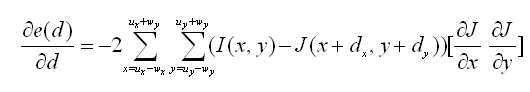
그런데 윈도우 크기에 비해서 d가 아주 작다고 한다면 1차 테일러 전개식에 의해서 다음과 같이 전개할 수 있다.However, if d is very small compared to the window size, it can be expanded as follows by the first Taylor expansion.
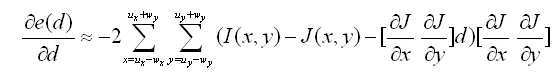
여기서 

또한Also

라고 하면, 수학식 4는 다음과 같이 다시 쓸 수 있다., Equation (4) can be rewritten as follows.

여기서 here
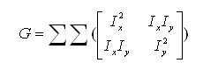
라 하고And

라 하면, 수학식 5는 다음과 같이 쓸 수 있다., Equation (5) can be written as follows.

따라서 수학식 6은 수학식 2에 의해서 다음과 같은 수학식 7로 집약된다.Thus, Equation (6) can be summarized as Equation (7) by Equation (2).
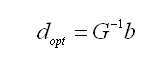
따라서 ![]()
![]()
therefore ![]()
![]()
상기의 문제점을 해결하기 위하여 본 실시예에서는 도2에 도시된 것처럼 영상의 해상도를 단계별로 낮추어서 여러 가지 저 해상도 버전을 만든 다음 가장 해상도가 낮은 영상에서부터 매칭을 진행해 나가는 것을 보여준다.In order to solve the above problem, in this embodiment, as shown in FIG. 2, the resolution of the image is lowered step by step, various low resolution versions are created, and matching from the lowest resolution image is proceeded.
도2 는 본 발명의 일 실시예에 따른 다양한 해상도를 갖도록 조정된 영상을 예시하는 개념도이다. 2 is a conceptual diagram illustrating an image adjusted to have various resolutions according to an embodiment of the present invention.
도 2을 참조하면 한 영상에 대하여 레벨0부터 레벨3까지의 해상도를 갖는 다른 버전의 영상이 생성된 것을 알 수 있다. 예를 들면, 레벨 0은 해상도를 조정하지 않은 초기의 영상이고, 레벨 1은 해상도를 한 단계 낮춘 영상, 레벨 2는 레벨 1에서 해상도를 한 단계 더 낮춘 영상, 레벨 3은 레벨 2에서 해상도를 한 단계 더 낮춘 영상이라고 할 수 있다. Referring to FIG. 2, it can be seen that another version of an image having a resolution ranging from level 0 to level 3 is generated for one image. For example, level 0 is the initial image without adjusting the resolution, level 1 is the image with lower resolution, level 2 is the image with lower resolution at level 1, level 3 is the resolution at level 2 It can be said to be a step-down video.
영상의 해상도를 낮추면 그만큼 영상간 변위d가 작아지는 효과를 가져오기 때문에 광흐름 기법을 이용하여 스테레오 매칭을 수행해도 충분히 원하는 효과를 얻을 수 있다. 또한, 최적의 해를 구하기 위하여 뉴턴-랩슨(Newton-Raphson) 접근법을 적용하여 위에서 표현된 수식들을 여러 번 반복하여 근접한 해를 찾아 나갈 수 있다. 뉴턴-랩슨 방법은 조금 불안정 하기는 하나 수렴이 빠른 것을 장점으로 하는 추정 방법이다.If the resolution of the image is lowered, the displacement d between the images is reduced. Therefore, even if the stereo matching is performed using the optical flow technique, the desired effect can be obtained sufficiently. In addition, we can use the Newton-Raphson approach to find the optimal solution and find the solution close to it by repeating the above expressions several times. The Newton-Raphson method is an estimation method that takes advantage of the fact that it is a little unstable but fast convergence.
또한 일반적으로 특징 기반의 스테레오 매칭 방법은 영상의 특징점 추적을 위하여 모서리, 선 및 코너 등과 관련된 점을 사용하여 왔다. 그러나 이들은 추적이 잘 될 것이라고 기대되는 특징을 가지고 있는 것으로 보이는 것일뿐, 사실상 추적이 잘 되리라는 보장은 없으므로, 추적이 잘되는 특징점을 잡는 것이 중요하다. 위의 식에서 그레디언트 행렬인 G 행렬의 경우, G 행렬의 고유값 중 작은 고유값이 큰 값을 가질수록 추적이 잘 되도록 설계되어 있다. 따라서 앞서 수식을 통하여 설명한 방법을 사용하여 추적이 잘 되는 특징점은 G행렬의 작은 고유값이(일반적으로 고유값은 두개가 존재하며, 그 중 작은 고유값을 일컬음) 큰 위치(x,y)일 것이다. Also, in general, feature-based stereo matching methods have used points related to edges, lines, and corners to track feature points of an image. However, since they seem to have the expected traits to be well tracked, there is no guarantee that tracking will actually work well, so it's important to keep track of well-characterized traits. In the above equation, in the case of the G matrix, which is a gradient matrix, the smaller the eigenvalues of the G matrix are, the larger the value is, the better the tracking is. Therefore, the feature point that is tracked using the method described in the previous equation is the small point (x, y) of the G matrix (usually two eigenvalues exist, will be.
영상의 각 위치에서 고유값을 계산하고, 특징점을 한 뒤, 작은 고유값이 큰 순서대로 원하는 개수의 특징점들을 나열하면 각 점들은 영상에서 고유값이 큰 점들의 집합이 될 것이며, 이러한 점들은 추적이 잘 되는 점이다.
After calculating the eigenvalues at each position of the image and after finding the feature points and arranging the desired number of feature points in the descending order of the small eigenvalues, each point will be a set of points with large eigenvalues in the image, This is a good point.
이하, 도면을 참조하여 위에 설명된 특징기반의 스테레오 매칭방법을 적용한 결과에 대한 다양한 예시 영상들을 살펴보기로 한다. 앞서 기술된 광흐름 기법을 이용한 스테레오 매핑 결과는 도 3내지 도 6에 예시된 영상을 통하여 확인할 수 있다.Hereinafter, various exemplary images of a result of applying the feature-based stereo matching method described above will be described with reference to the drawings. Stereo mapping results using the optical flow technique described above can be confirmed through the images illustrated in FIGS.
도 3은 본 발명의 일 실시예에 따른 특징 기반의 스테레오 매칭 방법을 이용하여 깊이 맵을 생성한 결과의 일 예를 보여주는 개념도이다. 3 is a conceptual diagram illustrating an example of a result of generating a depth map using a feature-based stereo matching method according to an embodiment of the present invention.
도 3을 참조하면 좌측 그림(310)은 원본 영상을 나타내며, 가운데 그림(320)은 원본 그림에서 각 특징점을 추적한 결과를 보여준다. 가운데 그림 (320)에서 검게 표시된 점은 멀리있는 점이며, 밝을수록 가까이 있는 점으로 추적된 것이다. 우측 그림(330)은 이러한 점들을 이용하여 깊이 맵을 구성한 것을 보여준다. 결과가 점들로 이루어져 있어서, 정확하지 않은 것처럼 보일 수 있지만, 이는 에피폴라 라인(epi-polar line)도 맞지 않고 교정(rectification)도 하지 않은 것이며, 어떠한 캘리브레이션도 없고, 서로 색감이나 밝기가 약간씩은 서로 다른 두 대의 카메라로부터 실시간으로 얻어진 것이라는 것을 고려할때 괜찮은 결과라는 것을 알 수 있다.
Referring to FIG. 3, the
도 4a 및 4b 본 발명의 일 실시예에 따른 특징 기반의 스테레오 매칭 방법을 이용한 사용자와 컴퓨터간의 인터랙션의 일 예를 보여주는 개념도이다. 4A and 4B are conceptual diagrams illustrating an example of interaction between a user and a computer using a feature-based stereo matching method according to an embodiment of the present invention.
도4a및 4b는 본 발명에 따른 따른 특징 기반의 스테레오 매칭 방법을 적용하여, 사람의 움직임을 컴퓨터가 인식하면서 상호 인터랙션을 하는 것을 보여준다. 도 4a및 4b의 좌측 그림(411,412,431,432)은 원본 영상이고, 우측 그림(421,422,441,442)은 각 원본 영상에 대하여 본 발명에 따른 광 흐름 기법을 이용하여 깊이 맵을 구성한 것이다. 도 4a를 참조하면 원본 영상(411,412)을 통하여, 사용자가 발차기 동작을 하고 있음을 알 수 있다. 또한 두 원본 영상(411,412) 각각에 대응하여 구성된 깊이 맵(4211,422)을 통해서도 사용자가 발차기 동작을 하고 있음을 인식할 수 있다. 이러한 결과로 볼때, 충분히 사용자와 컴퓨터 간의 인터랙션이 가능한 정확도로 구현되었음을 알수 있다.
FIGS. 4A and 4B illustrate how a stereo matching method according to the present invention is applied to perform a human interaction while interacting with a computer. The
도 5a 및 5b는 본 발명의 일 실시예에 따른 특징 기반의 스테레오 매칭 방법을 이용하여 깊이 맵을 생성한 결과의 다른 예를 보여주는 개념도이다.5A and 5B are conceptual diagrams showing another example of a result of generating a depth map using a feature-based stereo matching method according to an embodiment of the present invention.
도 5a는 카메라로 촬영된 원본 영상을 좌측 그림(510)에서 보여주고 있으며, 뒤에 백색 화살표로 표시된 부분은 원래 직선인데 곡선으로 표시되어 있다. 또한 우측에는 카메라로 촬영된 좌측 및 우측 영상을 겹쳐놓은 그림(520)을 보여주고 있는데, 사용자의 눈 위치의 높이가 다른 것을 볼 수 있다. 이와 같이 상기 영상들은 전혀 캘리브레이션 되지 않았다는 것을 알 수 있다. 도 5b는 이러한 영상에서 광흐름 기법을 이용하여 스테레오 매칭을 수행한 결과를 보여주고 있다. FIG. 5A shows an original image photographed by a camera in a
도 5b의 위쪽 그림들(531,532,533,534,535)은 시간차를 갖는 대응하는 동작을 겹쳐놓은 것처럼 보이지만, 사실은 동시에 공간을 달리하여 촬영한 영상을 겹쳐놓은 것이며, 사용자의 양 손의 위치를 찾아서 붉은색으로 표시해 주고 있다. 또한 이러한 영상들(531,532,533,534,535) 각각에 대하여 본 발명에 따른 광흐름 기법을 이용하여 구성된 깊이 맵이 아래쪽 그림(541,542,543,544,545)에 도시되어 있다. 아래쪽의 깊이 맵들(541,542,543,544,545)은 위쪽 그림(531,532,533,534,535)에 붉은 색으로 표시된 손부분의 위치를 정확하게 표현하고 있음을 알 수 있다.
The upper images (531, 532, 533, 534, 535) of FIG. 5b appear to overlap the corresponding motion with a time difference, but in fact, they overlap images taken at different spatial locations. have. For each of these
도 6은 본 발명의 일 실시예에 따른 특징 기반의 스테레오 매칭 방법을 이용한 사용자와 컴퓨터간의 인터랙션 용용예를 보여주는 개념도이다.FIG. 6 is a conceptual diagram illustrating an example of an interaction between a user and a computer using a feature-based stereo matching method according to an embodiment of the present invention.
도 6에는 사용자가 3D 모션을 이용하여 가상 키보드를 눌러서 아이디와 암호를 입력하는 그림(610), 사용자가 제스처를 이용하여 유투브를 검색하는 그림(620), 인터넷을 검색하는 그림(630)이 도시되어 있다. 또한 동영상이나 뮤직 비디오를 재생하면서 양 손을 이용하여 영상을 앞, 뒤로 움직이는 그림(640), 여러 개의 아이템을 양 손을 이용하여 탐색하는 그림(650), 양 손을 이용하여 자동차 레이싱 게임을 이용하는 그림(660)을 보여준다. 또한 사용자가 몸 전체를 이용하여 격투 게임을 즐기는 그림(670, 680)을 보여주는데, 팔 뿐만이 아니라 다리, 머리를 이용하여 컨텐츠를 가격하고 있는 것을 알 수 있다. 본 발명에 따른 스테레오 매칭방법을 적용하면 이와 같은 좀 더 정교한 인터랙션도 충분히 가능함을 알 수 있다.
FIG. 6 shows a
이상에서 설명된 광흐름 기법을 이용한 스테레오 매칭 방법은 이해를 돕기 위하여 제시된 예시이며 어떠한 광흐름 방법을 사용하여도 무방하다. 다만 기존에 시간차를 갖는 영상에 적용하였던 광흐름 방법을 공간차를 갖는 영상에 대하여 적용하여 스테레오 매칭을 수행하는 것이 본 발명의 특징이다.
The stereo matching method using the optical flow technique described above is an example presented for the sake of understanding and any optical flow method may be used. However, it is a feature of the present invention that an optical flow method applied to an image having a time difference is applied to an image having a spatial difference to perform stereo matching.
이하는 본발명에 따른 특징 기반의 스테레오 매칭을 좀 더 정확하게 수행하기 위하여 선택적으로 구성할 수 있는 기법들에 대해서 설명하기로 한다.
Hereinafter, techniques that can be selectively configured to more accurately perform feature-based stereo matching according to the present invention will be described.
최소한의 정보를 알고 있다면 추적 윈도우의 유연한 구성을 통하여 더욱 정확한 추적이 가능하다. 이하 도면을 참조하여 추적 윈도우를 구성하는 좀 더 상세한 실시예를 설명하기로 한다. If you know the least amount of information, more flexible tracking of the tracking window is possible. A more detailed embodiment of the tracking window will now be described with reference to the drawings.
도 7은 본 발명의 일 실시예에 따른 특징점 추적 윈도우의 구성을 예시하는 개념도이다.7 is a conceptual diagram illustrating a configuration of a feature point tracking window according to an embodiment of the present invention.
도 7의 (a)에 도시된 것처럼, 앞서 언급된 ![]()
![]()
![]()
![]()
그러나 만일 레퍼런스 카메라보다 비교 카메라가 더욱 오른쪽에 있다면 제대로 추적된 결과는 항상 오른쪽으로 추적되어 있어야 할 것이다. 이러한 경우 윈도우의 크기를 결정할 때, 도 7의 (b)와 같이 윈도우의 상하 폭을 줄여서 위쪽이나 아래쪽으로의 탐지 범위를 한정하고, 특징점의 추적 시작위치가 맨 왼쪽이 되어 우측 방향으로만 탐지하도록 윈도우의 중심점의 위치를 조정할 수 있을 것이다.However, if the comparison camera is farther to the right than the reference camera, properly tracked results should always be tracked to the right. In this case, when determining the size of the window, the upper and lower widths of the window are reduced to limit the detection range to the upper or lower side as shown in FIG. 7B, and the tracking start position of the minutiae is detected to the left You can adjust the position of the center point of the window.
또한 두 카메라 사이의 간격을 알고 있다면 휴리스틱하게 추적 거리가 너무 멀어지지 않도록 수식을 수정할 수도 있다. 마찬가지로 비교 카메라가 레퍼런스 카메라보다 조금 위쪽에 설치된 경우에는 추적이 아래쪽으로 진행되지 않도록 도 7의 (c)와 같이 윈도우의 크기와 모양 및 중심점의 위치를 조정할 수 있을 것이다. 즉 카메라의 상대적 위치나 간격과 같은 최소한의 사전 정보를 가지고도 추적 윈도우의 크기, 모양 또는 중심점의 위치를 조정함으로서 최적의 특징 기반 스테레오 매칭 방법을 구현할 수 있다.
Also, if you know the distance between two cameras, you can modify the formula so that the tracking distance is not too far away. Similarly, if the comparison camera is installed slightly above the reference camera, the size, shape, and center point of the window may be adjusted as shown in FIG. 7 (c) so that the tracking does not proceed downward. In other words, the optimal feature-based stereo matching method can be implemented by adjusting the size, shape, or center point of the tracking window even with minimal prior information such as the relative position or interval of the camera.
한편 역광과 같은 배경의 영향이 있는 경우 영상에 나타난 사용자의 모션을 정확하게 인식하기 어려움이 있다. 이를 해결하기 위한 방법으로서, 본 실시예에서는 앞서 제시된 영상의 전경과 배경을 분리하여 영상의 전경에 대해서만 스테레오 매칭을 수행할 수 있도록 하는 방법을 좀 더 자세하게 설명하기로 한다.On the other hand, it is difficult to accurately recognize the motion of the user displayed on the image if the backlight affects the background. As a method for solving this problem, a method of performing stereo matching only on the foreground of an image by separating the foreground and background of the previously presented image will be described in more detail.
도 8은 역광이 있는 배경의 영향을 받은 영상과 이에 대한 스테레오 매칭결과의 일 예를 보여주는 개념도이다.8 is a conceptual diagram showing an example of a stereo-matching result and a video image affected by a backlit background.
도 9는 본 발명의 일 실시예에 따른 적외선 조명이 부착된 카메라를 예시하는 개념도이다.9 is a conceptual diagram illustrating a camera with infrared light according to an embodiment of the present invention.
도 8을 참조하면 좌측 그림(810)은 원본 영상이고 우측 그림(820)은 원본 영상에 대한 깊이 맵을 생성한 결과를 보여준다. 좌측 그림(810)을 참조하면, 사용자가 오른손을 들고 왼손을 뒷짐지고 있는 것을 알 수 있다. 그러나 좌측 그림(810)에 대한 깊이 맵인 우측 그림(820)만으로는 사용자의 실제적인 모션이 무엇인지를 파악하기가 어렵다. 이는 사용자 뒤쪽의 역광으로 인해 사용자의 3D 모션이 제대로 인식되지 못하기 때문이다.Referring to FIG. 8, the
따라서 더욱 강인한 3D 모션의 인식을 위해서 도 9에 도시된 것과 같은 형태의 카메라 구성을 활용할 수 있다. 도 9의 카메라 구성은 적외선(IR LED) 조명을 포함하고 있으며 이를 이용하여 전경과 배경을 분리해 낼 수 있다. 즉, 카메라쪽에 적외선 조명이 부착되어 있으므로 카메라로부터 멀리 있는 영역은 어둡게 표현된다. 이에 따라, 일정 밝기값 이하의 영역을 제거하여 사용자의 모습 즉 전경만을 취할 수 있을 것이다.Therefore, in order to recognize a stronger 3D motion, a camera configuration as shown in FIG. 9 can be utilized. The camera configuration of FIG. 9 includes infrared (IR) LED illumination, which allows the foreground and background to be separated. In other words, since the infrared light is attached to the camera, the area far from the camera is darkened. Accordingly, it is possible to remove a region having a predetermined brightness value or less and to take a view of the user, that is, only the foreground.
여기서 일정 밝기값으로는 각 영역의 그 동안의 밝기 값을 참조하여 결정된 밝기 값을 기준으로 적용할 수 있다. 또는 영역의 일정 비율만을 전경으로 분리하는 등의 방법을 적용할 수도 있을 것이다. 이와 같이, 시간의 흐름에 따라 가변적으로 설정되는 것으로, 자동적으로 정해지도록 할 수 있다. 도 9는 카메라 구성의 예시로서 IEEE 1394 인터페이스의 카메라와 USB 인터페이스의 카메라를 모두 장착했지만, 영상에서 전경/배경을 분리하기 위한 최소한의 기구적 구성은 두 개의 영상 센서 (CCD 나 CMOS 등) 와 적외선 조명(IR LED) 이다.
Here, the predetermined brightness value can be applied based on the brightness value determined by referring to the brightness values of the respective regions. Or a method of separating only a certain percentage of the area into the foreground may be applied. In this way, it is set variably according to the passage of time, and can be automatically determined. FIG. 9 shows an example of the camera configuration in which both the
또한 앞에서 설명한 바와 같이 레퍼런스 영상에서 특징점을 선택한 뒤에 비교영상에서 동일한 위치를 추적하는 비대칭 방법을 사용할 수도 있지만, 이와는 다르게 양쪽 영상에서 모두 특징점을 찾은 뒤 이것을 서로 다른 영상에서 광흐름 기법을 이용하여 추적하는 대칭 방법을 사용할 수도 있다. 이하, 이와 같은 대칭방법을 적용하여 특징점을 추적하는 방법에 대해서 설명하기로 한다. Also, as described above, it is possible to use an asymmetric method of tracking the same position in a reference image after selecting a feature point in a reference image. However, unlike the above method, a feature point is found in both images and then the feature point is tracked using a light flow technique A symmetric method may also be used. Hereinafter, a method of tracking feature points by applying the symmetric method will be described.
도 10은 본 발명의 다른 실시예에 따른 대칭방법을 적용한 특징기반의 스테레오 매칭 과정을 보여주는 시퀀스 챠트이다.FIG. 10 is a sequence chart illustrating a feature-based stereo matching process using a symmetry method according to another embodiment of the present invention.
도 10을 참조하면 본 발명의 대칭방법을 적용한 특징기반의 스테레오 매칭방법은 영상수집 단계(S210), 영상에 대한 해상도 조절단계(S220), 레퍼런스 영상에서 제 1특징점 추출단계 (S230), 비교 영상에서 제 2특징점 추출단계 (S240), 비교 영상에서 제 1대응점 추적단계 (S250), 레퍼런스 영상에서 제 2대응점 추적단계 (S260), 깊이 맵 생성단계(S270)를 포함하여 구성될 수 있다.Referring to FIG. 10, a feature-based stereo matching method using the symmetric method of the present invention includes an image collecting step S210, a resolution adjusting step S220, a first feature point extracting step S230, (S240), a first corresponding point tracking step (S250), a second corresponding point tracking step (S260), and a depth map generating step (S270) in the reference image.
도 10을 참조하면, 본 발명의 다른 실시예에 따른 대칭방법을 적용한 스테레오 매칭 방법의 각 단계는 다음과 같이 설명될 수 있다. Referring to FIG. 10, each step of the stereo matching method using the symmetry method according to another embodiment of the present invention can be described as follows.
영상수집 단계(S110)는 복수의 카메라를 이용하여 촬영된 복수개의 영상을 컴퓨터를 이용하여 수집하는 단계이다. 본 발명의 실시예에서는 두 대의 카메라를 통하여 수집된 영상을 이용한다. The image collection step S110 is a step of collecting a plurality of images photographed using a plurality of cameras using a computer. In the embodiment of the present invention, images collected through two cameras are used.
영상의 해상도 조절단계(S230)는 레퍼런스 영상과 비교 영상 각각에 대하여, 본래의 영상보다 해상도를 낮춘 여러 버전의 영상을 생성하는 단계이다. 이는 특징점 추출시 해상도가 가장 낮은 버전의 영상에서부터 수행하도록 하여, 영상간의 변이차가 낮은 상태에서부터 특징점 추적을 시작함으로써 좀 더 정확한 매칭 결과를 얻기 위함이다. The step of adjusting the resolution of the image (S230) is a step of generating multiple versions of images for each of the reference image and the comparison image, the resolution of which is lower than that of the original image. This is to obtain a more accurate matching result by starting the feature point tracking from the state in which the difference between the images is low, by performing the feature point extraction from the version with the lowest resolution.
레퍼런스 영상에서 제 1특징점 추출단계 (S230)와 비교 영상에서 제 2특징점 추출단계 (S240)는 각각 레퍼런스 영상 및 비교 영상 영상에서 추적이 잘될수 있는 제1 특징점과 제 2 특징점을 찾는 단계이다.The first feature point extraction step (S230) and the second feature point extraction step (S240) in the reference image are a step of finding a first feature point and a second feature point that can be tracked in the reference image and the comparison image, respectively.
비교 영상에서 제 1대응점 추적단계 (S250)는 광흐름(Optical Flow)기법을 이용하여, 앞서 찾은 제1 특징점에 대응하는 제1 대응점의 위치를 비교 영상에서 추적하는 단계이다.The first correspondence point tracking step S250 in the comparison image is a step of tracking the position of the first corresponding point corresponding to the first feature point found in the comparison image using the optical flow technique.
레퍼런스 영상에서 제2대응점 추적단계 (S260)는 광흐름(Optical Flow)기법을 이용하여, 앞서 찾은 제 2특징점에 대응하는 제2 대응점의 위치를 레퍼런스 영상에서 추적하는 단계이다.The second correspondence point tracking step S260 in the reference image is a step of tracking the position of the second corresponding point corresponding to the second feature point found in the reference image using the optical flow technique.
깊이 맵 생성단계(S260)는 앞서 수행된 추적 결과를 이용하여 깊이 맵을 구성하여 3차원 영상을 복원하기 위한 단계이다. The depth map generation step S260 is a step for reconstructing a three-dimensional image by constructing a depth map using the tracking results obtained previously.
본 대칭 방법은 요건에 따라 특징점 추출 및 대응점 추적을 레퍼런스 영상과 비교 영상에 대하여 병행으로 수행 할 수도 있고, 순차적으로 수행 할 수도 있을것이다. 병행으로 수행하면 좀 더 고속의 매칭이 될 것이지만 높은 사양의 장치를 요구할 것이다. 또한 이러한 대칭방법은 좀 더 정교한 깊이 맵을 생성할 수 있을 것이다.
In this symmetric method, feature point extraction and correspondence point tracking may be performed in parallel to the reference image and the comparison image according to requirements, or sequentially. Performing in parallel will be a faster match, but will require a higher specification device. In addition, this symmetric method can generate more sophisticated depth maps.
이하 본 발명에 따른 특징기반의 스테레오 매칭 방법을 수행하는 스테레오 매칭 장치에 대해서 도면을 참조하여 설명하기로 한다.Hereinafter, a stereo matching apparatus for performing a feature-based stereo matching method according to the present invention will be described with reference to the drawings.
도 11는 본 발명의 일 실시예에 따른 특징 기반의 스테레오 매칭 장치를 보여주는 개념도이다. 11 is a conceptual diagram illustrating a feature-based stereo matching apparatus according to an embodiment of the present invention.
도 11을 참조하면, 본 발명의 특징 기반의 스테레오 매칭 장치는 카메라(1110), 영상 획득부(1120), 전경/배경 분리부(1130), 해상도 조정부(1140), 특징점 추출부(1150), 대응점 추적부(1160), 깊이 맵 생성부(1170)를 포함하여 구성된다.11, a stereo matching apparatus based on features of the present invention includes a camera 1110, an
도 11을 참조하면 본 발명의 광흐름 기법을 이용한 스테레오 매칭 장치의 각 구성요소는 다음과 같이 설명될 수 있다.Referring to FIG. 11, the components of the stereo matching apparatus using the optical flow technique of the present invention can be described as follows.
카메라(1110)는 발명에 따른 장치가 수행되는 컴퓨터에 내장되거나 또는 외부에 설치되어 연결되도록 구성될 수 있으며, 적어도 두 개의 카메라가 이용된다. 각 카메라에는 적외선광이 내장되거나 외부에 부착될 수 있다. 본 발명에 따른 복 수의 카메라는 공간적으로 일정한 간격을 갖도록 설치되며, 동시에 촬영되도록 구성된다. The camera 1110 can be configured to be built in or connected externally to a computer in which the apparatus according to the invention is performed, and at least two cameras are used. Each camera can be equipped with infrared light or attached to the outside. The multiple cameras according to the present invention are installed so as to have spatially constant intervals and are configured to be photographed at the same time.
영상 수집부(1120)는 복수의 카메라를 이용하여 촬영된 복수의 영상을 수집한다. 하나의 영상은 레퍼런스 영상(10)으로, 나머지는 참조 영상(20)으로 이용된다. 레퍼런스 영상(10)은 특징점을 추출하기 위한 기준이 되는 영상이며, 참조 영상(20)은 레퍼런스 영상(10)에서 추출한 특징점에 대응되는 점을 찾기위한 영상이다.The
전경/배경 분리부(1130)는 수집된 복수개의 각 영상에서 전경을 배경으로부터 분리한다. 이는 전경에 대해서만 특징점을 추적할 수 있도록함으로써, 역광이나 배경 등에 민감한 영상을 좀 더 정확하게 분석하기 위함이다. The foreground /
해상도 조정부(1140)는 수집된 또는 전경이 분리된 레퍼런스 영상(10)과 참조 영상(20) 각각에 대하여, 본래의 영상보다 해상도를 낮춘 여러 버전의 영상을 생성하는 단계이다. 이는 특징점 추출시 해상도가 가장 낮은 버전의 영상에서부터 수행하도록 하여, 영상간의 변이차가 낮은 상태에서부터 특징점 추적을 시작함으로써 좀 더 정확한 매칭 결과를 얻기 위함이다. The
특징점 추출부(1150)는 레퍼런스 영상(10)에서 추적이 잘될수 있는 특징점을 추출하고, 대응점 추적부(1160)는 광흐름(Optical Flow)기법을 이용하여, 앞서 찾은 특징점에 대응하는 점의 위치를 비교영상(20)에서 추적한다. 이때 도7에 도시된 특징점 추적 윈도우를 이용하여 카메라의 위치나 카메라간의 간격과 같은 미리 주어진 정보에 따라서 대응점 검색범위를 한정하도록 추적 윈도우를 조정함으로써 좀 더 빠르고 정확하게 대응점을 찾을 수 있을 것이다. The feature
깊이 맵 생성부(1170)는 특징점에 대응하는 위치의 추적 결과를 이용하여 깊이 맵을 생성하는데, 이는 캘리브레이션을 수행하지 않기 때문에 고속의 깊이 맵(30)의 형성이 가능하다.
The depth
이번에는 양쪽 영상에서 모두에서 특징점과 대응점을 찾는 대칭방법을 적용한 스테레오 매칭 장치에 대하여 설명하기로 한다. Hereinafter, a stereo matching apparatus to which a symmetric method of finding the minutiae and corresponding points in both images will be described.
도 12는 본 발명의 다른 실시예에 따른 대칭방법을 적용한 특징기반의 스테레오 매칭 장치를 보여주는 개념도이다. FIG. 12 is a conceptual diagram showing a feature-based stereo matching apparatus to which a symmetric method according to another embodiment of the present invention is applied.
도 12를 참조하면, 본 발명에 따른 대칭방법을 적용한 스테레오 매칭 장치는 카메라(1210), 영상 획득부(1220), 해상도 조정부(1230), 제1특징점 추출부(1240), 제2특징점 추출부(1250), 제1대응점 추적부(1260), 제2대응점 추적부(1270), 깊이 맵 생성부(1180)를 포함하여 구성된다.12, a stereo matching apparatus using a symmetric method according to the present invention includes a camera 1210, an
도 12를 참조하면, 본 발명의 따른 대칭방법을 적용한 스테레오 매칭 장치의 각 구성요소는 다음과 같이 설명될 수 있다. Referring to FIG. 12, each component of the stereo matching apparatus applying the symmetry method according to the present invention can be described as follows.
카메라(1210)는 발명에 따른 장치가 수행되는 컴퓨터에 내장되거나 또는 외부에 설치되어 연결되도록 구성될 수 있으며, 본 실시예에서는 두 대의 카메라가 이용되며, 공간적으로 일정한 간격을 갖도록 설치되며, 동시에 촬영되도록 구성된다. The camera 1210 may be built in or connected to a computer in which the apparatus according to the present invention is implemented. In this embodiment, two cameras are used. The camera 1210 is installed so as to have a spatially constant interval, .
영상 수집부(1220)는 두 개 카메라를 이용하여 각각 촬영된 레퍼런스 영상(40)과 비교 영상(50)을 수집한다. The
제1 특징점 추출부(1240)는 레퍼런스 영상에서 추적이 잘 될수 있는 제1 특징점을 찾고, 제2 특징점 추출부(1250)는 비교 영상에서 추적이 잘 될수 있는 제 2 특징점을 찾는다. The first feature point extractor 1240 finds a first feature point that can be tracked in the reference image and the second feature point extractor 1250 finds a second feature point that can be tracked in the comparison image.
제 1대응점 추적부(1260)는 광흐름(Optical Flow)기법을 이용하여, 앞서 찾은 제1 특징점에 대응하는 제1 대응점의 위치를 비교 영상에서 추적한다.The first correspondence point tracking unit 1260 tracks the position of the first corresponding point corresponding to the first feature point found in the comparison image using the optical flow technique.
제2대응점 추적부 (1270)는 광흐름(Optical Flow)기법을 이용하여, 앞서 찾은 제 2특징점에 대응하는 제2 대응점의 위치를 레퍼런스 영상에서 추적한다.The second corresponding point tracking unit 1270 tracks the position of the second corresponding point corresponding to the second feature point found in the reference image using the optical flow technique.
특징점 추출 및 대응점 추적부는 요건에 따라서 제1 특징점 추출 및 대응점 추적이 완료된후 제2 제2 특징점 추출 및 제2 대응점 추적이 수행되도록 순차적으로 동작할 수도 있고, 제1 및 제2 특징점 추출과 대응점 추적이 동시에 수행되도록 동작할 수 도 있다. The feature point extraction and correspondence point tracking unit may operate sequentially so that the second feature point extraction and the second correspondence point tracking are performed after the first feature point extraction and the corresponding point tracking are completed according to the requirements, and the first and second feature point extraction and correspondence point tracking Can be operated simultaneously.
깊이 맵 생성부(1280)는 특징점 추출 및 대응점 추적 결과를 이용하여 깊이 맵을 구성하여 3차원 영상을 복원하게 된다.
The depth
또한 본 발명에 따른 장치는 필요한 기구의 구조상 박막형태로 제작이 가능하기 때문에 도 13에 예시된 것처럼 노트북 LCD측에 부착하여 3D 제스처 인터페이스를 사용할 수 있다.
In addition, since the apparatus according to the present invention can be manufactured in the form of a thin film on the structure of a necessary apparatus, it can be attached to the notebook LCD side and used as a 3D gesture interface as illustrated in FIG.
상기에서는 본 발명의 바람직한 실시예를 참조하여 설명하였지만, 해당 기술 분야의 숙련된 당업자는 하기의 특허 청구의 범위에 기재된 본 발명의 사상 및 영역으로부터 벗어나지 않는 범위 내에서 본 발명을 다양하게 수정 및 변경시킬 수 있음을 이해할 수 있을 것이다.
It will be apparent to those skilled in the art that various modifications and variations can be made in the present invention without departing from the spirit or scope of the present invention as defined by the following claims It can be understood that
Claims (18)
상기 레퍼런스 영상과 상기 적어도 하나의 비교 영상을 수집하는 단계;
상기 레퍼런스 영상에서 특징점들을 추출하는 단계;
광 흐름 기법을 이용하여, 상기 적어도 하나의 각 비교 영상에서 상기 각 특징점들에 대응되는 점들을 추적하는 대응점 추적단계; 및
상기 대응점 추적 결과에 따라 깊이 맵을 생성하는 단계를 포함하고,
상기 레퍼런스 영상에서 특징점들을 추출하는 단계는,
상기 레퍼런스 영상의 각 위치에서 그레디언트 행렬 G의 고유값을 계산하고, 그 결과로 산출된 두 개의 고유값 중 작은 고유값에 대하여 내림차순으로 각 해당하는 점들을 나열함으로써, 일정순위 내의 점들을 추출하는 스테레오 매칭 방법.A method for performing stereo matching on a reference image photographed from another viewpoint and at least one comparison image using a computer device,
Collecting the reference image and the at least one comparison image;
Extracting feature points from the reference image;
A corresponding point tracking step of tracking points corresponding to the respective minutiae points in the at least one comparison image using an optical flow technique; And
Generating a depth map according to the correspondence point tracking result,
Wherein the extracting of the feature points from the reference image comprises:
Extracting points in a certain order by calculating the eigenvalues of the gradient matrix G at each position of the reference image and arranging the corresponding points in descending order of the small eigenvalues among the two eigenvalues calculated as a result, Matching method.
상기 레퍼런스 영상과 상기 적어도 하나의 비교 영상 각각에 대하여, 본래의 영상보다 해상도를 일정 단계별로 낮추어서, 다양한 해상도 레벨을 갖는 영상을 생성하되, 본래 영상보다 해상도가 낮은 적어도 하나의 영상을 생성하는 단계를 더 포함하고, 상기 특징점 추출 및 대응점 추적은 해상도가 가장 낮은 레퍼런스 영상과 이에 대응하는 비교 영상에서부터 시작하여, 본래의 해상도를 갖는 레퍼런스 영상과 이에 대응하는 비교 영상에 대해서 최종적으로 수행하는 것을 특징으로 하는 스테레오 매칭 방법.The method according to claim 1,
Generating at least one image having a different resolution level by lowering the resolution of each of the reference image and the at least one comparison image by a predetermined step than the original image and having a resolution lower than that of the original image; And the feature point extraction and correspondence point tracking are finally performed on the reference image having the original resolution and the corresponding comparison image starting from the reference image having the lowest resolution and the corresponding comparison image, Stereo matching method.
상기 광흐름 기법에 뉴턴-랩슨(Newton-Raphson) 방법을 적용함으로써, 여러 번 반복하여 근접한 대응점을 찾는 것을 특징으로 하는 스테레오 매칭 방법.The method according to claim 1,
And applying the Newton-Raphson method to the optical flow technique to find a corresponding point that is repeated several times.
상기 대응점 추적단계는,
상기 레퍼런스 영상에서 상기 특징점에 대응하는 점들을 추적하기 위한, 특징점 추적 윈도우를 구성하는 단계를 포함하고, 상기 특징점 추적 윈도우는 미리 제공된 정보에 따라서, 윈도우의 크기, 모양 및 중심점의 위치가 변경되는 것을 특징으로 하는 스테레오 매칭 방법.The method according to claim 1,
In the step of tracking the corresponding point,
And a step of constructing a feature point tracking window for tracking points corresponding to the feature point in the reference image, wherein the feature point tracking window is configured to change the position of the window size, shape, and center point according to information provided in advance / RTI >
상기 미리 제공된 정보는 적어도 두 대의 카메라간의 상대적 위치, 배치 간격 중 적어도 하나를 포함하는 것을 특징으로 하는 스테레오 매칭 방법.6. The method of claim 5,
Wherein the pre-provided information includes at least one of a relative position and an arrangement interval between at least two cameras.
상기 레퍼런스 영상과 상기 적어도 하나의 비교 영상의 전경과 배경을 분리시키는 단계를 더 포함하고,
상기 레퍼런스 영상과 상기 적어도 하나의 비교 영상은 각각 적외선 조명을 이용하여 촬영되고, 상기 특징점 추출과 상기 대응점 추적은 각각 상기 레퍼런스 영상의 전경 및 상기 적어도 하나의 비교 영상의 전경에 대해서 수행되는 것을 특징으로 하는 스테레오 매칭 방법.The method according to claim 1,
Further comprising separating foreground and background of the reference image and the at least one comparison image,
Wherein the reference image and the at least one comparison image are respectively photographed using infrared illumination and the feature point extraction and the corresponding point tracking are performed on the foreground of the reference image and the foreground of the at least one comparison image, / RTI >
상기 각 영상으로부터 전경과 배경을 분리시키는 방법은 상기 각 영상에서 일정한 밝기 이상의 영역을 전경으로 분리하거나 또는 영상의 일정한 비율을 전경으로 분리하는 것을 특징으로 하는 스테레오 매칭 방법.8. The method of claim 7,
Wherein the method for separating foreground and background from each image separates an area of a predetermined brightness or more in each of the images into foreground images or separates a predetermined ratio of images into foreground images.
상기 레퍼런스 영상 및 적어도 하나의 비교 영상은 적어도 2개의 카메라로 동일한 시각에 다른 관점에서 촬영된 것을 특징으로 하는 스테레오 매칭 방법.The method according to claim 1,
Wherein the reference image and the at least one comparison image are photographed by at least two cameras at the same time from different viewpoints.
상기 레퍼런스 영상과 상기 적어도 하나의 비교영상을 수집하는 단계;
상기 레퍼런스 및 상기 적어도 하나의 비교 영상 각각에 대하여, 본래의 영상보다 해상도를 일정 단계별로 낮추어서, 다양한 해상도 레벨을 갖는 영상을 생성하되, 본래 영상보다 해상도가 낮은 적어도 하나의 영상을 생성하는 단계;
상기 레퍼런스 영상에서 제1특징점들을 추출하는 단계;
광 흐름 기법을 이용하여, 상기 적어도 하나의 각 비교 영상에서, 상기 각 제1 특징점들에 대응되는 제 1 대응점들을 추적하는 단계;
상기 적어도 하나의 각 비교 영상에서 제 2 특징점들을 추출하는 단계;
광 흐름 기법을 이용하여, 상기 레퍼런스 영상에 대하여, 상기 각 제 2 특징점들에 대응되는 제 2 대응점들을 추적하는 단계; 및
상기 제 1 및 제 2 대응점 추적 결과를 합성하여 깊이 맵을 생성하는 단계를 포함하고,
상기 제1 및 제2 특징점 추출과 상기 제1 및 제2 대응점 추적은 해상도가 가장 낮은 영상들에 대해서부터 시작하여, 본래의 해상도를 갖는 영상들에 대해서 최종적으로 수행하고,
상기 제1 특징점들을 추출하는 단계 및 상기 제2 특징점들을 추출하는 단계는,
상기 레퍼런스 영상 및 적어도 하나의 비교 영상의 각 위치에서 그레디언트 행렬 G의 고유값을 계산하고, 그 결과로 산출된 두 개의 고유값 중 작은 고유값에 대하여 내림차순으로 각 해당하는 점들을 나열함으로써, 일정순위 내의 점들을 추출하는 것을 특징으로 하는 스테레오 매칭 방법.A method for performing stereo matching on a reference image photographed from another viewpoint and at least one comparison image using a computer device,
Collecting the reference image and the at least one comparison image;
Generating at least one image having a different resolution level by lowering the resolution of each of the reference and the at least one comparison image by a predetermined step than the original image and having a resolution lower than that of the original image;
Extracting first feature points from the reference image;
Using light flow techniques to track first corresponding points corresponding to each of the first feature points in the at least one respective comparison image;
Extracting second feature points from the at least one respective comparison image;
Tracking second reference points corresponding to the second reference points with respect to the reference image using an optical flow technique; And
And generating a depth map by synthesizing the first and second corresponding point tracking results,
The first and second feature point extraction and the first and second corresponding point tracking are finally performed on images having the original resolution, starting from the images having the lowest resolution,
Wherein the extracting of the first feature points and the extracting of the second feature points comprise:
By calculating the eigenvalues of the gradient matrix G at the respective positions of the reference image and the at least one comparison image and by listing the corresponding points in descending order of the small eigenvalues among the two eigenvalues calculated as a result, And extracting points within the stereo matching step.
상기 레퍼런스 영상과 상기 적어도 하나의 비교 영상을 수집하는 영상 수집부;
상기 레퍼런스 영상에서 특징점들을 추출하되, 상기 레퍼런스 영상의 각 위치의 그레디언트 행렬의 고유값을 계산하고, 그 결과로 산출된 두 개의 고유값 중 작은 고유값에 대하여 내림차순으로 각 해당하는 점들을 나열함으로써, 일정순위 내의 점들을 특징점으로 추출하는 특징점 추출부;
광 흐름 기법을 이용하여, 상기 적어도 하나의 비교영상에서 각각 상기 각 특징점들에 대응되는 점들을 추적하는 대응점 추적부; 및
상기 대응점들 추적 결과를 이용하여 깊이 맵을 생성하는 깊이 맵 생성부를 포함하는 것을 특징으로 하는 스테레오 매칭 장치.An apparatus for stereo matching using a reference image photographed from another viewpoint and at least one comparison image,
An image collection unit for collecting the reference image and the at least one comparison image;
The feature point extraction unit extracts feature points from the reference image, calculates eigenvalues of a gradient matrix at each position of the reference image, and lists corresponding points in descending order of small eigenvalues among the two eigenvalues calculated as a result, A feature point extracting unit for extracting points within a predetermined order as feature points;
A correspondence point tracking unit for tracking points corresponding to each of the minutiae points in the at least one comparison image using an optical flow technique; And
And a depth map generator for generating a depth map using the correspondence points tracking result.
상기 레퍼런스 영상과 적어도 하나의 비교영상 각각에 대하여, 본래의 영상보다 해상도를 일정 단계별로 낮추어서, 다양한 해상도 레벨을 갖는 영상을 생성하되, 본래 영상보다 해상도가 낮은 적어도 하나의 영상을 생성하는 해상도 조정부를 더 포함하고, 상기 특징점 추출 및 대응점 추적은 해상도가 가장 낮은 레퍼런스 영상과 이에 대응하는 비교영상에서부터 시작하여, 본래의 해상도를 갖는 레퍼런스 영상과 이에 대응하는 비교 영상에 대해서 최종적으로 수행하는 것을 특징으로 하는 스테레오 매칭 장치.13. The method of claim 12,
A resolution adjusting unit for generating an image having various resolution levels by lowering the resolution of each of the reference image and the at least one comparison image by a predetermined step rather than the original image and generating at least one image having a resolution lower than that of the original image; And the feature point extraction and correspondence point tracking are finally performed on the reference image having the original resolution and the corresponding comparison image starting from the reference image having the lowest resolution and the corresponding comparison image, Stereo matching device.
상기 대응점 추적부는 특징점 추적 윈도우를 이용하여 상기 레퍼런스 영상에서 상기 특징점에 대응하는 점들을 추적하고, 상기 특징점 추적 윈도우는
적어도 두 대의 카메라간의 상대적 위치, 배치 간격 중 적어도 하나의 정보를 기초로, 윈도우의 크기, 모양 및 중심점의 위치가 변경되는 것을 특징으로 하는 스테레오 매칭 장치.13. The method of claim 12,
Wherein the corresponding point tracking unit tracks points corresponding to the feature points in the reference image using a feature point tracking window,
Wherein the size, shape, and position of the center point of the window are changed based on at least one of the relative position and the arrangement interval between the at least two cameras.
상기 레퍼런스 영상과 상기 적어도 하나의 영상에서 각각 전경과 배경을 분리하되, 상기 각 영상의 일정한 밝기 이상의 영역 또는 일정한 비율을 전경으로 분리하는 전경/배경 분리부를 더 포함하고, 상기 레퍼런스 영상과 상기 적어도 하나의 비교 영상은 각각 적외선 조명을 이용하여 촬영되고, 상기 특징점 추출과 상기 광흐름 기법을 이용한 대응점 추적은 각각 상기 레퍼런스 영상 및 상기 적어도 하나의 비교 영상의 전경에 대해서 수행되는 것을 특징으로 하는 스테레오 매칭 장치.13. The method of claim 12,
Further comprising a foreground / background separator for separating the foreground and background from the reference image and the at least one image, respectively, wherein the foreground / background separator separates the foreground and background from the reference image and the at least one image, Wherein the comparison images of the reference image and the at least one comparison image are respectively photographed using infrared light illumination and the corresponding point extraction using the optical flow technique is performed for the foreground of the reference image and the at least one comparison image, .
상기 적어도 하나의 비교 영상에서 제 2 특징점들을 추출하는 제 2 특징점 추출부; 및
광 흐름 기법을 이용하여, 상기 레퍼런스 영상에서, 상기 각 제 2 특징점들에 대응되는 점을 추출하는 제 2 대응점 추적부를 더 포함하고,
상기 깊이 맵 생성부는 상기 대응점 추적 결과에 상기 제2 대응점 추적결과를 합성하여 상기 깊이 맵을 생성하는 것을 특징으로 하는 스테레오 매칭 장치.13. The method of claim 12,
A second feature point extractor for extracting second feature points from the at least one comparison image; And
Further comprising a second corresponding point tracking unit for extracting points corresponding to the respective second feature points from the reference image using an optical flow technique,
Wherein the depth map generator generates the depth map by combining the second corresponding point tracking result with the corresponding point tracking result.
상기 레퍼런스 영상 및 적어도 하나의 비교 영상은 적어도 2개의 카메라로 동일한 시각에 다른 관점에서 촬영된 것을 특징으로 하는 스테레오 매칭 장치.13. The method of claim 12,
Wherein the reference image and the at least one comparison image are photographed by at least two cameras at the same time from different viewpoints.
상기 스테레오 매칭 장치는 박막 형태로 제작되어 컴퓨터의 LCD 측에 내장하거나 부착하는 것을 특징으로 하는 스테레오 매칭 장치.
13. The method of claim 12,
Wherein the stereo matching device is fabricated in a thin film form and embedded or affixed to the LCD side of the computer.
Priority Applications (2)
| Application Number | Priority Date | Filing Date | Title |
|---|---|---|---|
| KR1020110023400A KR101792501B1 (en) | 2011-03-16 | 2011-03-16 | Method and apparatus for feature-based stereo matching |
| US13/413,170 US8787656B2 (en) | 2011-03-16 | 2012-03-06 | Method and apparatus for feature-based stereo matching |
Applications Claiming Priority (1)
| Application Number | Priority Date | Filing Date | Title |
|---|---|---|---|
| KR1020110023400A KR101792501B1 (en) | 2011-03-16 | 2011-03-16 | Method and apparatus for feature-based stereo matching |
Publications (2)
| Publication Number | Publication Date |
|---|---|
| KR20120105764A KR20120105764A (en) | 2012-09-26 |
| KR101792501B1 true KR101792501B1 (en) | 2017-11-21 |
Family
ID=46828493
Family Applications (1)
| Application Number | Title | Priority Date | Filing Date |
|---|---|---|---|
| KR1020110023400A Expired - Fee Related KR101792501B1 (en) | 2011-03-16 | 2011-03-16 | Method and apparatus for feature-based stereo matching |
Country Status (2)
| Country | Link |
|---|---|
| US (1) | US8787656B2 (en) |
| KR (1) | KR101792501B1 (en) |
Families Citing this family (90)
| Publication number | Priority date | Publication date | Assignee | Title |
|---|---|---|---|---|
| US8902321B2 (en) | 2008-05-20 | 2014-12-02 | Pelican Imaging Corporation | Capturing and processing of images using monolithic camera array with heterogeneous imagers |
| US11792538B2 (en) | 2008-05-20 | 2023-10-17 | Adeia Imaging Llc | Capturing and processing of images including occlusions focused on an image sensor by a lens stack array |
| US8866920B2 (en) | 2008-05-20 | 2014-10-21 | Pelican Imaging Corporation | Capturing and processing of images using monolithic camera array with heterogeneous imagers |
| WO2011063347A2 (en) | 2009-11-20 | 2011-05-26 | Pelican Imaging Corporation | Capturing and processing of images using monolithic camera array with heterogeneous imagers |
| US8446492B2 (en) * | 2009-12-10 | 2013-05-21 | Honda Motor Co., Ltd. | Image capturing device, method of searching for occlusion region, and program |
| KR101824672B1 (en) | 2010-05-12 | 2018-02-05 | 포토네이션 케이맨 리미티드 | Architectures for imager arrays and array cameras |
| US8878950B2 (en) | 2010-12-14 | 2014-11-04 | Pelican Imaging Corporation | Systems and methods for synthesizing high resolution images using super-resolution processes |
| CN103765864B (en) | 2011-05-11 | 2017-07-04 | 派力肯影像公司 | Systems and methods for transmitting and receiving array camera image data |
| WO2013043751A1 (en) | 2011-09-19 | 2013-03-28 | Pelican Imaging Corporation | Systems and methods for controlling aliasing in images captured by an array camera for use in super resolution processing using pixel apertures |
| US8542933B2 (en) | 2011-09-28 | 2013-09-24 | Pelican Imaging Corporation | Systems and methods for decoding light field image files |
| US9033795B2 (en) * | 2012-02-07 | 2015-05-19 | Krew Game Studios LLC | Interactive music game |
| WO2013126578A1 (en) | 2012-02-21 | 2013-08-29 | Pelican Imaging Corporation | Systems and methods for the manipulation of captured light field image data |
| JP2015534734A (en) | 2012-06-28 | 2015-12-03 | ペリカン イメージング コーポレイション | System and method for detecting defective camera arrays, optical arrays, and sensors |
| US20140002674A1 (en) | 2012-06-30 | 2014-01-02 | Pelican Imaging Corporation | Systems and Methods for Manufacturing Camera Modules Using Active Alignment of Lens Stack Arrays and Sensors |
| WO2014031795A1 (en) | 2012-08-21 | 2014-02-27 | Pelican Imaging Corporation | Systems and methods for parallax detection and correction in images captured using array cameras |
| CN104685513B (en) | 2012-08-23 | 2018-04-27 | 派力肯影像公司 | According to the high-resolution estimation of the feature based of the low-resolution image caught using array source |
| CN103793920B (en) * | 2012-10-26 | 2017-10-13 | 杭州海康威视数字技术股份有限公司 | Retrograde detection method and its system based on video |
| CN103856777A (en) * | 2012-12-04 | 2014-06-11 | 中山大学深圳研究院 | Video coding and decoding method based on optical field rendering |
| US9171373B2 (en) * | 2012-12-26 | 2015-10-27 | Ncku Research And Development Foundation | System of image stereo matching |
| US20140192158A1 (en) * | 2013-01-04 | 2014-07-10 | Microsoft Corporation | Stereo Image Matching |
| CN103974055B (en) * | 2013-02-06 | 2016-06-08 | 城市图像科技有限公司 | 3D photo generation system and method |
| US9462164B2 (en) | 2013-02-21 | 2016-10-04 | Pelican Imaging Corporation | Systems and methods for generating compressed light field representation data using captured light fields, array geometry, and parallax information |
| US9774789B2 (en) | 2013-03-08 | 2017-09-26 | Fotonation Cayman Limited | Systems and methods for high dynamic range imaging using array cameras |
| US8866912B2 (en) | 2013-03-10 | 2014-10-21 | Pelican Imaging Corporation | System and methods for calibration of an array camera using a single captured image |
| US9134114B2 (en) | 2013-03-11 | 2015-09-15 | Texas Instruments Incorporated | Time of flight sensor binning |
| WO2014164550A2 (en) | 2013-03-13 | 2014-10-09 | Pelican Imaging Corporation | System and methods for calibration of an array camera |
| WO2014164909A1 (en) | 2013-03-13 | 2014-10-09 | Pelican Imaging Corporation | Array camera architecture implementing quantum film sensors |
| WO2014159779A1 (en) | 2013-03-14 | 2014-10-02 | Pelican Imaging Corporation | Systems and methods for reducing motion blur in images or video in ultra low light with array cameras |
| WO2014153098A1 (en) | 2013-03-14 | 2014-09-25 | Pelican Imaging Corporation | Photmetric normalization in array cameras |
| US9445003B1 (en) | 2013-03-15 | 2016-09-13 | Pelican Imaging Corporation | Systems and methods for synthesizing high resolution images using image deconvolution based on motion and depth information |
| US9633442B2 (en) * | 2013-03-15 | 2017-04-25 | Fotonation Cayman Limited | Array cameras including an array camera module augmented with a separate camera |
| US9497429B2 (en) | 2013-03-15 | 2016-11-15 | Pelican Imaging Corporation | Extended color processing on pelican array cameras |
| EP2973476B1 (en) | 2013-03-15 | 2025-02-26 | Adeia Imaging LLC | Systems and methods for stereo imaging with camera arrays |
| US10122993B2 (en) | 2013-03-15 | 2018-11-06 | Fotonation Limited | Autofocus system for a conventional camera that uses depth information from an array camera |
| KR101677559B1 (en) | 2013-03-22 | 2016-11-18 | 한국전자통신연구원 | Image registration device and operation method thereof |
| US9384551B2 (en) * | 2013-04-08 | 2016-07-05 | Amazon Technologies, Inc. | Automatic rectification of stereo imaging cameras |
| US10268885B2 (en) | 2013-04-15 | 2019-04-23 | Microsoft Technology Licensing, Llc | Extracting true color from a color and infrared sensor |
| KR20150004989A (en) * | 2013-07-03 | 2015-01-14 | 한국전자통신연구원 | Apparatus for acquiring 3d image and image processing method using the same |
| KR102069269B1 (en) | 2014-01-21 | 2020-01-22 | 한화테크윈 주식회사 | Apparatus and method for stabilizing image |
| US10136063B2 (en) | 2013-07-12 | 2018-11-20 | Hanwha Aerospace Co., Ltd | Image stabilizing method and apparatus |
| WO2015048694A2 (en) | 2013-09-27 | 2015-04-02 | Pelican Imaging Corporation | Systems and methods for depth-assisted perspective distortion correction |
| US10119808B2 (en) | 2013-11-18 | 2018-11-06 | Fotonation Limited | Systems and methods for estimating depth from projected texture using camera arrays |
| WO2015081279A1 (en) | 2013-11-26 | 2015-06-04 | Pelican Imaging Corporation | Array camera configurations incorporating multiple constituent array cameras |
| CN103745458B (en) * | 2013-12-26 | 2015-07-29 | 华中科技大学 | A kind of space target rotating axle based on binocular light flow of robust and mass center estimation method |
| KR20150103507A (en) | 2014-03-03 | 2015-09-11 | 삼성전자주식회사 | Method of unlocking an electronic device based on motion recognitions, motion recognition unlocking system, and electronic device including the same |
| WO2015134996A1 (en) | 2014-03-07 | 2015-09-11 | Pelican Imaging Corporation | System and methods for depth regularization and semiautomatic interactive matting using rgb-d images |
| CN105335952B (en) * | 2014-06-19 | 2018-04-17 | 株式会社理光 | Matching power flow computational methods and device and parallax value calculating method and equipment |
| WO2016054089A1 (en) | 2014-09-29 | 2016-04-07 | Pelican Imaging Corporation | Systems and methods for dynamic calibration of array cameras |
| CN104408743A (en) * | 2014-11-05 | 2015-03-11 | 百度在线网络技术(北京)有限公司 | Image segmentation method and device |
| US9803985B2 (en) * | 2014-12-26 | 2017-10-31 | Here Global B.V. | Selecting feature geometries for localization of a device |
| AT517656A1 (en) * | 2015-08-20 | 2017-03-15 | Ait Austrian Inst Of Tech G M B H | Photometric Stereomatching |
| KR20170040571A (en) | 2015-10-05 | 2017-04-13 | 한국전자통신연구원 | Apparatus and method for generating depth information |
| TW201742001A (en) * | 2016-05-30 | 2017-12-01 | 聯詠科技股份有限公司 | Method and device for image noise estimation and image capture apparatus |
| US10462445B2 (en) | 2016-07-19 | 2019-10-29 | Fotonation Limited | Systems and methods for estimating and refining depth maps |
| US10839535B2 (en) | 2016-07-19 | 2020-11-17 | Fotonation Limited | Systems and methods for providing depth map information |
| CN106327473A (en) * | 2016-08-10 | 2017-01-11 | 北京小米移动软件有限公司 | Method and device for acquiring foreground images |
| EP3500822A4 (en) * | 2016-08-18 | 2019-08-28 | SZ DJI Technology Co., Ltd. | SYSTEMS AND METHODS FOR INCREASED STEREOSCOPIC DISPLAY |
| KR101905813B1 (en) * | 2016-09-09 | 2018-10-08 | 광운대학교 산학협력단 | Device for comparing image files |
| KR102507383B1 (en) * | 2016-11-08 | 2023-03-08 | 한국전자통신연구원 | Method and system for stereo matching by using rectangular window |
| US10755428B2 (en) * | 2017-04-17 | 2020-08-25 | The United States Of America, As Represented By The Secretary Of The Navy | Apparatuses and methods for machine vision system including creation of a point cloud model and/or three dimensional model |
| KR101956198B1 (en) * | 2017-07-27 | 2019-03-11 | 두림야스카와(주) | Method for car type recognition of panting system |
| US10482618B2 (en) | 2017-08-21 | 2019-11-19 | Fotonation Limited | Systems and methods for hybrid depth regularization |
| US11284107B2 (en) * | 2017-08-22 | 2022-03-22 | Google Llc | Co-located reference frame interpolation using optical flow estimation |
| US11917128B2 (en) | 2017-08-22 | 2024-02-27 | Google Llc | Motion field estimation based on motion trajectory derivation |
| US10659788B2 (en) | 2017-11-20 | 2020-05-19 | Google Llc | Block-based optical flow estimation for motion compensated prediction in video coding |
| CN108055510B (en) * | 2017-12-25 | 2018-10-12 | 北京航空航天大学 | A kind of real-time apparatus for correcting of two-way video based on FPGA and method |
| CN108492326B (en) * | 2018-01-31 | 2021-11-23 | 北京大学深圳研究生院 | Stereo matching method and system with gradually refined resolution ratio from low to high |
| US10986325B2 (en) * | 2018-09-12 | 2021-04-20 | Nvidia Corporation | Scene flow estimation using shared features |
| GB2578789A (en) * | 2018-11-09 | 2020-05-27 | Sony Corp | A method, apparatus and computer program for image processing |
| US11223817B2 (en) | 2018-11-12 | 2022-01-11 | Electronics And Telecommunications Research Institute | Dual stereoscopic image display apparatus and method |
| CN109470216A (en) * | 2018-11-19 | 2019-03-15 | 国网四川省电力公司电力科学研究院 | Robot binocular vision feature point location method |
| BR112022004811A2 (en) | 2019-09-17 | 2022-06-21 | Boston Polarimetrics Inc | Systems and methods for surface modeling using polarization indications |
| CN114746717A (en) | 2019-10-07 | 2022-07-12 | 波士顿偏振测定公司 | System and method for surface normal sensing using polarization |
| KR20230116068A (en) | 2019-11-30 | 2023-08-03 | 보스턴 폴라리메트릭스, 인크. | System and method for segmenting transparent objects using polarization signals |
| WO2021154386A1 (en) | 2020-01-29 | 2021-08-05 | Boston Polarimetrics, Inc. | Systems and methods for characterizing object pose detection and measurement systems |
| KR20220133973A (en) | 2020-01-30 | 2022-10-05 | 인트린식 이노베이션 엘엘씨 | Systems and methods for synthesizing data to train statistical models for different imaging modalities, including polarized images |
| CN111504229A (en) * | 2020-04-10 | 2020-08-07 | 武汉理工大学 | Method for dynamically projecting patterns for visual measurement matching on curved plate |
| US11953700B2 (en) | 2020-05-27 | 2024-04-09 | Intrinsic Innovation Llc | Multi-aperture polarization optical systems using beam splitters |
| US12069227B2 (en) | 2021-03-10 | 2024-08-20 | Intrinsic Innovation Llc | Multi-modal and multi-spectral stereo camera arrays |
| US12020455B2 (en) | 2021-03-10 | 2024-06-25 | Intrinsic Innovation Llc | Systems and methods for high dynamic range image reconstruction |
| US11290658B1 (en) | 2021-04-15 | 2022-03-29 | Boston Polarimetrics, Inc. | Systems and methods for camera exposure control |
| US11954886B2 (en) | 2021-04-15 | 2024-04-09 | Intrinsic Innovation Llc | Systems and methods for six-degree of freedom pose estimation of deformable objects |
| US12067746B2 (en) | 2021-05-07 | 2024-08-20 | Intrinsic Innovation Llc | Systems and methods for using computer vision to pick up small objects |
| US12175741B2 (en) | 2021-06-22 | 2024-12-24 | Intrinsic Innovation Llc | Systems and methods for a vision guided end effector |
| US12340538B2 (en) | 2021-06-25 | 2025-06-24 | Intrinsic Innovation Llc | Systems and methods for generating and using visual datasets for training computer vision models |
| US12172310B2 (en) | 2021-06-29 | 2024-12-24 | Intrinsic Innovation Llc | Systems and methods for picking objects using 3-D geometry and segmentation |
| US11689813B2 (en) | 2021-07-01 | 2023-06-27 | Intrinsic Innovation Llc | Systems and methods for high dynamic range imaging using crossed polarizers |
| US12293535B2 (en) | 2021-08-03 | 2025-05-06 | Intrinsic Innovation Llc | Systems and methods for training pose estimators in computer vision |
| KR102860337B1 (en) | 2022-11-01 | 2025-09-16 | 삼성전자주식회사 | Method and apparatus for generating hyperlapse video |
| CN117315033B (en) * | 2023-11-29 | 2024-03-19 | 上海仙工智能科技有限公司 | An identification and positioning method, system and storage medium based on neural network |
Citations (2)
| Publication number | Priority date | Publication date | Assignee | Title |
|---|---|---|---|---|
| JP2001167249A (en) * | 1999-12-06 | 2001-06-22 | Sanyo Electric Co Ltd | Method and device for synthesizing image and recording medium stored with image synthesizing program |
| JP2006527443A (en) * | 2003-06-12 | 2006-11-30 | 本田技研工業株式会社 | Target orientation estimation using depth detection |
Family Cites Families (9)
| Publication number | Priority date | Publication date | Assignee | Title |
|---|---|---|---|---|
| US5764871A (en) * | 1993-10-21 | 1998-06-09 | Eastman Kodak Company | Method and apparatus for constructing intermediate images for a depth image from stereo images using velocity vector fields |
| US6046763A (en) * | 1997-04-11 | 2000-04-04 | Nec Research Institute, Inc. | Maximum flow method for stereo correspondence |
| KR20010084212A (en) | 2000-02-24 | 2001-09-06 | 윤종용 | Method and system of data communication between computer and environmental apparatus |
| US7085409B2 (en) * | 2000-10-18 | 2006-08-01 | Sarnoff Corporation | Method and apparatus for synthesizing new video and/or still imagery from a collection of real video and/or still imagery |
| US6847728B2 (en) * | 2002-12-09 | 2005-01-25 | Sarnoff Corporation | Dynamic depth recovery from multiple synchronized video streams |
| KR100919166B1 (en) | 2007-04-02 | 2009-09-28 | 한국과학기술원 | Stereo Moire Measurement Apparatus and Method |
| KR100899422B1 (en) | 2007-08-06 | 2009-05-27 | 삼성모바일디스플레이주식회사 | Stereo Matching System and Stereo Matching Method Using the Same |
| KR20090055803A (en) | 2007-11-29 | 2009-06-03 | 광주과학기술원 | Method and apparatus for generating multiview depth map and method for generating variance in multiview image |
| KR100951637B1 (en) | 2007-12-17 | 2010-04-09 | 한국전자통신연구원 | Stereo Vision System and Its Image Processing Method |
-
2011
- 2011-03-16 KR KR1020110023400A patent/KR101792501B1/en not_active Expired - Fee Related
-
2012
- 2012-03-06 US US13/413,170 patent/US8787656B2/en not_active Expired - Fee Related
Patent Citations (2)
| Publication number | Priority date | Publication date | Assignee | Title |
|---|---|---|---|---|
| JP2001167249A (en) * | 1999-12-06 | 2001-06-22 | Sanyo Electric Co Ltd | Method and device for synthesizing image and recording medium stored with image synthesizing program |
| JP2006527443A (en) * | 2003-06-12 | 2006-11-30 | 本田技研工業株式会社 | Target orientation estimation using depth detection |
Also Published As
| Publication number | Publication date |
|---|---|
| US8787656B2 (en) | 2014-07-22 |
| KR20120105764A (en) | 2012-09-26 |
| US20120237114A1 (en) | 2012-09-20 |
Similar Documents
| Publication | Publication Date | Title |
|---|---|---|
| KR101792501B1 (en) | Method and apparatus for feature-based stereo matching | |
| KR101733131B1 (en) | 3D motion recognition method and apparatus | |
| US11095869B2 (en) | System and method for generating combined embedded multi-view interactive digital media representations | |
| US9237330B2 (en) | Forming a stereoscopic video | |
| Kong et al. | Intrinsic depth: Improving depth transfer with intrinsic images | |
| WO2021178919A1 (en) | Systems and methods for depth estimation by learning triangulation and densification of sparse points for multi-view stereo | |
| US20140241612A1 (en) | Real time stereo matching | |
| KR100888081B1 (en) | Conversion procedure and device for converting 2D video signal to 3D video signal | |
| CN106896925A (en) | The device that a kind of virtual reality is merged with real scene | |
| CN101180653A (en) | Method and device for three-dimensional rendering | |
| US20180189955A1 (en) | Augumented reality (ar) method and system enhanced through efficient edge detection of image objects | |
| US12261990B2 (en) | System and method for generating combined embedded multi-view interactive digital media representations | |
| Tripathi et al. | A statistical approach to continuous self-calibrating eye gaze tracking for head-mounted virtual reality systems | |
| Li et al. | Robust RGB-D face recognition using Kinect sensor | |
| US20250391158A1 (en) | Generation method, non-transitory computer-readable recording medium, and information processing device | |
| JP2023553914A (en) | Apparatus and method for processing depth maps | |
| CN107016730A (en) | The device that a kind of virtual reality is merged with real scene | |
| KR100799990B1 (en) | 3D image conversion device and method of 2D image | |
| CN116129016B (en) | Digital synchronization method, device and equipment for gesture movement and storage medium | |
| CN110678905B (en) | Apparatus and method for processing depth map | |
| Saxena et al. | 3-d reconstruction from sparse views using monocular vision | |
| CN106981100A (en) | The device that a kind of virtual reality is merged with real scene | |
| KR100560464B1 (en) | How to configure a multiview image display system adaptive to the observer's point of view | |
| KR20150040194A (en) | Apparatus and method for displaying hologram using pupil track based on hybrid camera | |
| Lyubanenko et al. | Multi-camera finger tracking and 3d trajectory reconstruction for hci studies |
Legal Events
| Date | Code | Title | Description |
|---|---|---|---|
| PA0109 | Patent application |
St.27 status event code: A-0-1-A10-A12-nap-PA0109 |
|
| PG1501 | Laying open of application |
St.27 status event code: A-1-1-Q10-Q12-nap-PG1501 |
|
| PN2301 | Change of applicant |
St.27 status event code: A-3-3-R10-R13-asn-PN2301 St.27 status event code: A-3-3-R10-R11-asn-PN2301 |
|
| PA0201 | Request for examination |
St.27 status event code: A-1-2-D10-D11-exm-PA0201 |
|
| P22-X000 | Classification modified |
St.27 status event code: A-2-2-P10-P22-nap-X000 |
|
| P22-X000 | Classification modified |
St.27 status event code: A-2-2-P10-P22-nap-X000 |
|
| D13-X000 | Search requested |
St.27 status event code: A-1-2-D10-D13-srh-X000 |
|
| P22-X000 | Classification modified |
St.27 status event code: A-2-2-P10-P22-nap-X000 |
|
| D14-X000 | Search report completed |
St.27 status event code: A-1-2-D10-D14-srh-X000 |
|
| E902 | Notification of reason for refusal | ||
| PE0902 | Notice of grounds for rejection |
St.27 status event code: A-1-2-D10-D21-exm-PE0902 |
|
| E13-X000 | Pre-grant limitation requested |
St.27 status event code: A-2-3-E10-E13-lim-X000 |
|
| P11-X000 | Amendment of application requested |
St.27 status event code: A-2-2-P10-P11-nap-X000 |
|
| P13-X000 | Application amended |
St.27 status event code: A-2-2-P10-P13-nap-X000 |
|
| E701 | Decision to grant or registration of patent right | ||
| PE0701 | Decision of registration |
St.27 status event code: A-1-2-D10-D22-exm-PE0701 |
|
| GRNT | Written decision to grant | ||
| PR0701 | Registration of establishment |
St.27 status event code: A-2-4-F10-F11-exm-PR0701 |
|
| PR1002 | Payment of registration fee |
St.27 status event code: A-2-2-U10-U11-oth-PR1002 Fee payment year number: 1 |
|
| PG1601 | Publication of registration |
St.27 status event code: A-4-4-Q10-Q13-nap-PG1601 |
|
| P22-X000 | Classification modified |
St.27 status event code: A-4-4-P10-P22-nap-X000 |
|
| P22-X000 | Classification modified |
St.27 status event code: A-4-4-P10-P22-nap-X000 |
|
| PR1001 | Payment of annual fee |
St.27 status event code: A-4-4-U10-U11-oth-PR1001 Fee payment year number: 4 |
|
| PC1903 | Unpaid annual fee |
St.27 status event code: A-4-4-U10-U13-oth-PC1903 Not in force date: 20211027 Payment event data comment text: Termination Category : DEFAULT_OF_REGISTRATION_FEE |
|
| PC1903 | Unpaid annual fee |
St.27 status event code: N-4-6-H10-H13-oth-PC1903 Ip right cessation event data comment text: Termination Category : DEFAULT_OF_REGISTRATION_FEE Not in force date: 20211027 |