KR101785456B1 - Apparatus and system for providing wireless power charge service - Google Patents
Apparatus and system for providing wireless power charge service Download PDFInfo
- Publication number
- KR101785456B1 KR101785456B1 KR1020110038424A KR20110038424A KR101785456B1 KR 101785456 B1 KR101785456 B1 KR 101785456B1 KR 1020110038424 A KR1020110038424 A KR 1020110038424A KR 20110038424 A KR20110038424 A KR 20110038424A KR 101785456 B1 KR101785456 B1 KR 101785456B1
- Authority
- KR
- South Korea
- Prior art keywords
- electronic device
- information
- power
- target electronic
- unit
- Prior art date
- Legal status (The legal status is an assumption and is not a legal conclusion. Google has not performed a legal analysis and makes no representation as to the accuracy of the status listed.)
- Active
Links
Images


Classifications
-
- G—PHYSICS
- G07—CHECKING-DEVICES
- G07F—COIN-FREED OR LIKE APPARATUS
- G07F15/00—Coin-freed apparatus with meter-controlled dispensing of liquid, gas or electricity
- G07F15/003—Coin-freed apparatus with meter-controlled dispensing of liquid, gas or electricity for electricity
- G07F15/006—Coin-freed apparatus with meter-controlled dispensing of liquid, gas or electricity for electricity dispensed for the electrical charging of other devices than vehicles
-
- H—ELECTRICITY
- H02—GENERATION; CONVERSION OR DISTRIBUTION OF ELECTRIC POWER
- H02J—CIRCUIT ARRANGEMENTS OR SYSTEMS FOR SUPPLYING OR DISTRIBUTING ELECTRIC POWER; SYSTEMS FOR STORING ELECTRIC ENERGY
- H02J50/00—Circuit arrangements or systems for wireless supply or distribution of electric power
- H02J50/10—Circuit arrangements or systems for wireless supply or distribution of electric power using inductive coupling
- H02J50/12—Circuit arrangements or systems for wireless supply or distribution of electric power using inductive coupling of the resonant type
-
- H—ELECTRICITY
- H02—GENERATION; CONVERSION OR DISTRIBUTION OF ELECTRIC POWER
- H02J—CIRCUIT ARRANGEMENTS OR SYSTEMS FOR SUPPLYING OR DISTRIBUTING ELECTRIC POWER; SYSTEMS FOR STORING ELECTRIC ENERGY
- H02J50/00—Circuit arrangements or systems for wireless supply or distribution of electric power
- H02J50/80—Circuit arrangements or systems for wireless supply or distribution of electric power involving the exchange of data, concerning supply or distribution of electric power, between transmitting devices and receiving devices
-
- H—ELECTRICITY
- H02—GENERATION; CONVERSION OR DISTRIBUTION OF ELECTRIC POWER
- H02J—CIRCUIT ARRANGEMENTS OR SYSTEMS FOR SUPPLYING OR DISTRIBUTING ELECTRIC POWER; SYSTEMS FOR STORING ELECTRIC ENERGY
- H02J50/00—Circuit arrangements or systems for wireless supply or distribution of electric power
- H02J50/90—Circuit arrangements or systems for wireless supply or distribution of electric power involving detection or optimisation of position, e.g. alignment
-
- H02J7/44—
-
- H02J7/47—
-
- H02J7/485—
-
- H02J7/731—
-
- H02J7/82—
Landscapes
- Engineering & Computer Science (AREA)
- Computer Networks & Wireless Communication (AREA)
- Power Engineering (AREA)
- Physics & Mathematics (AREA)
- General Physics & Mathematics (AREA)
- Charge And Discharge Circuits For Batteries Or The Like (AREA)
Abstract
본 명세서는 인증을 통해 무선 충전 서비스를 제공함으로써, 공용의 무선 충전 장치를 이용하여 무선 충전 서비스를 제공받고자 하는 다수의 전자기기들에 대한 충전 권한을 효율적으로 제어하여 사용자에게 안정적인 무선 충전 서비스를 제공함과 동시에 사업자에게 새로운 이윤 창출 모델을 제시하는 무선 충전 장치 및 시스템에 관한 것이다. 이를 위해 본 명세서에 개시된 일 실시 예에 따른 무선 충전 장치는 서버로부터 대상 전자기기의 인증 결과 정보를 수신하는 무선 통신부; 및 상기 인증 결과 정보가 인증 성공을 나타내는 경우에 상기 대상 전자기기에 무선으로 전력을 송신하는 무선 충전부를 포함하고, 상기 무선 통신부는, 상기 인증 결과 정보가 인증 실패를 나타내는 경우에 상기 대상 전자기기에 상기 인증 결과 정보를 송신한다.The present disclosure provides a wireless charging service for a user by efficiently controlling charging authority for a plurality of electronic devices to receive a wireless charging service by using a public wireless charging device by providing a wireless charging service through authentication And a wireless charging device and system for presenting a new profit generating model to a business entity. To this end, the wireless charging device according to an embodiment disclosed herein may include a wireless communication unit for receiving authentication result information of a target electronic device from a server; And a wireless charging unit that wirelessly transmits power to the target electronic device when the authentication result information indicates authentication success, wherein the wireless communication unit is configured to transmit, when the authentication result information indicates authentication failure, And transmits the authentication result information.
Description
본 명세서는 전자기기에 관한 것으로서, 특히 무선 충전 서비스를 제공하는 무선 충전 장치 및 시스템에 관한 것이다.BACKGROUND OF THE
사용자의 각종 전자 기기들은 휴대성이 강조됨에 따라 점차 보다 배터리의 효율이 중요시되고 있다. 따라서 배터리를 고효율화하고자 하는 다양한 기술들이 제시되었다. 이와 같이 배터리를 고효율화하고자 하는 시도들은 있었으나, 배터리의 충전에 있어서는 큰 진전이 없었다.As the portability of various electronic devices of users is emphasized, the efficiency of the battery gradually becomes more important. Therefore, various technologies for high efficiency of the battery have been suggested. There have been attempts to increase the efficiency of the battery, but there has been no significant progress in charging the battery.
특히, 각 전자 기기의 충전을 위해서는 전원 어댑터를 각기 구비해야 하기 때문에, 사용자에 있어서는 매우 번거로운 노고가 아닐 수 없었다. 최근에는 전자 기기를 무선으로 충전하기 위한 여러 연구들이 진행되고 있다. 상기 무선 충전은 충전을 위한 선을 제거하고, 전자기적으로 에너지를 전달할 수 있는 획기적인 에너지 전달 개념이다.Particularly, since each power supply adapter must be provided for charging each electronic device, it is very troublesome for the user. In recent years, various studies have been conducted to wirelessly charge electronic devices. The wireless charging is an epoch-making energy transfer concept that removes the line for charging and can transfer energy electronically.
본 명세서는 인증을 통해 무선 충전 서비스를 제공함으로써, 공용의 무선 충전 장치를 이용하여 무선 충전 서비스를 제공받고자 하는 다수의 전자기기들에 대한 충전 권한을 효율적으로 제어하여 사용자에게 안정적인 무선 충전 서비스를 제공함과 동시에 사업자에게 새로운 이윤 창출 모델을 제시하는 무선 충전 장치 및 시스템을 제공하는 데 그 목적이 있다.The present disclosure provides a wireless charging service for a user by efficiently controlling charging authority for a plurality of electronic devices to receive a wireless charging service by using a public wireless charging device by providing a wireless charging service through authentication And a wireless charging device and system for presenting a new profit generating model to a business entity.
또한, 본 명세서는 제한된 무선 충전 환경에서 전력 정보를 기준으로 다수의 전자기기들 사이의 충전 우선 순위를 설정함으로써, 무선 충전 서비스를 제공받고자 하는 다수의 전자기기들에 대한 사용자에게 효율적인 무선 충전 서비스를 제공하는 무선 충전 장치 및 시스템을 제공하는 데 그 목적이 있다.In addition, the present specification sets a charge priority among a plurality of electronic devices on the basis of power information in a limited wireless charging environment, thereby providing an efficient wireless charging service to a plurality of electronic devices to receive a wireless charging service The present invention provides a wireless charging device and a system for providing the wireless charging device.
상술한 과제를 실현하기 위한 본 명세서에 개시된 일 실시예에 따른 무선 충전 장치는 서버로부터 대상 전자기기의 인증 결과 정보를 수신하는 무선 통신부; 및 상기 인증 결과 정보가 인증 성공을 나타내는 경우에 상기 대상 전자기기에 무선으로 전력을 송신하는 무선 충전부를 포함하고, 상기 무선 통신부는, 상기 인증 결과 정보가 인증 실패를 나타내는 경우에 상기 대상 전자기기에 상기 인증 결과 정보를 송신한다.The wireless charging apparatus according to an embodiment disclosed herein for realizing the above-mentioned problems includes a wireless communication unit for receiving authentication result information of a target electronic device from a server; And a wireless charging unit that wirelessly transmits power to the target electronic device when the authentication result information indicates authentication success, wherein the wireless communication unit is configured to transmit, when the authentication result information indicates authentication failure, And transmits the authentication result information.
일 실시예에 있어서, 상기 무선 통신부는 상기 대상 전자기기로부터 식별 정보를 수신하고, 상기 식별 정보에 기초하여 상기 서버에 상기 인증 결과 정보를 요청한다.In one embodiment, the wireless communication unit receives the identification information from the target electronic device, and requests the server for the authentication result information based on the identification information.
또한 일 실시예에 있어서, 상기 무선 충전부는 상기 대상 전자기기로부터 식별 정보를 수신하고, 상기 무선 통신부는 상기 식별 정보에 기초하여 상기 서버에 상기 인증 결과 정보를 요청한다.In one embodiment, the wireless charging unit receives identification information from the target electronic device, and the wireless communication unit requests the authentication result information to the server based on the identification information.
또한 일 실시예에 있어서, 상기 무선 통신부는 상기 대상 전자기기에 결제 정보를 요청한다.In one embodiment, the wireless communication unit requests payment information from the target electronic device.
또한 일 실시예에 있어서, 상기 무선 통신부는 상기 대상 전자기기로부터 상기 요청된 결제 정보를 수신하고, 상기 수신한 결제 정보를 상기 서버에 송신한다.In one embodiment, the wireless communication unit receives the requested payment information from the target electronic device, and transmits the received payment information to the server.
또한 일 실시예에 있어서, 상기 무선 통신부는 상기 서버로부터 상기 결제 정보에 대한 승인 정보를 수신하고, 상기 수신한 승인 정보를 상기 대상 전자기기에 송신한다.In one embodiment, the wireless communication unit receives the approval information for the payment information from the server, and transmits the approval information to the target electronic device.
또한 일 실시예에 있어서, 상기 무선 통신부는 상기 서버로부터 상기 대상 전자기기의 과금 정보를 수신하고, 상기 무선 충전부는 상기 수신한 과금 정보에 기초하여 상기 대상 전자기기에 무선으로 전력을 송신한다.In one embodiment, the wireless communication unit receives charging information of the target electronic device from the server, and the wireless charging unit wirelessly transmits power to the target electronic device based on the received charging information.
또한 일 실시예에 있어서, 상기 무선 통신부는 상기 대상 전자기기가 무선으로 전력을 수신할 수 있는 영역에 존재하는 경우에 상기 서버로부터 상기 대상 전자기기의 인증 결과 정보를 수신한다.In one embodiment, the wireless communication unit receives authentication result information of the target electronic device from the server when the target electronic device exists in an area where wireless power can be received.
또한 일 실시예에 있어서, 상기 무선 통신부는 상기 대상 전자기기가 무선으로 전력을 수신할 수 없는 영역에 존재하는 경우에 상기 서버로부터 상기 대상 전자기기의 인증 결과 정보를 수신한다.In one embodiment, the wireless communication unit receives the authentication result information of the target electronic device from the server when the target electronic device exists in an area where wireless power can not be received.
또한 일 실시예에 있어서, 상기 무선 통신부는 상기 대상 전자기기가 무선으로 데이터를 송수신할 수 있는 영역에 존재하는 경우에 상기 서버로부터 상기 대상 전자기기의 인증 결과 정보를 수신한다.In one embodiment, the wireless communication unit receives authentication result information of the target electronic device from the server when the target electronic device exists in an area where data can be wirelessly transmitted and received.
한편, 상술한 과제를 실현하기 위한 본 명세서에 개시된 일 실시예에 따른 무선 충전 장치는 제1 및 제2 전자기기 각각으로부터 전력 정보를 수신하는 무선 통신부; 상기 제1 및 제2 전자기기 각각의 전력 정보에 기초하여 상기 제1 및 제2 전자기기 중 어느 하나를 대상 전자기기로 결정하는 제어부; 및 상기 대상 전자기기에 무선으로 전력을 송신하는 무선 충전부를 포함한다.According to another aspect of the present invention, there is provided a wireless charging apparatus including: a wireless communication unit for receiving power information from a first electronic device and a second electronic device; A control unit for determining any one of the first and second electronic devices as a target electronic device based on the power information of each of the first and second electronic devices; And a wireless charging unit for wirelessly transmitting power to the target electronic device.
일 실시예에 있어서, 상기 전력 정보는 대응하는 전자기기의 전력 상태 정보 및 전력 제어 정보 중 적어도 하나를 포함한다.In one embodiment, the power information includes at least one of power state information and power control information of a corresponding electronic device.
또한 일 실시예에 있어서, 상기 전력 상태 정보는 대응하는 전자기기의 전력 잔량 정보 및 무선 통신을 위한 최소 전력 요구량에 관한 정보를 포함한다.Also, in one embodiment, the power state information includes information on power remaining amount information of a corresponding electronic device and information on a minimum power requirement amount for wireless communication.
또한 일 실시예에 있어서, 상기 전력 상태 정보는 대응하는 전자기기의 무선 데이터 통신량에 관한 정보를 포함한다.In one embodiment, the power status information includes information on a wireless data traffic amount of a corresponding electronic device.
또한 일 실시예에 있어서, 상기 전력 제어 정보는 대응하는 전자기기의 우선 충전 여부에 관한 정보를 더 포함한다.In one embodiment, the power control information further includes information on whether or not the corresponding electronic device is firstly charged.
또한 일 실시예에 있어서, 상기 제어부는 상기 무선 충전부가 상기 대상 전자기기에 무선으로 전력을 송신하는 것을 중단하는지 모니터링하고, 상기 중단이 감지된 경우에 상기 제1 및 제2 전자기기 중 상기 대상 전자기기를 제외한 나머지 하나를 새로운 대상 전자기기로 결정한다.In one embodiment, the controller monitors whether the wireless charger interrupts wirelessly sending power to the target electronic device, and when the suspend is detected, The remaining one is determined as a new target electronic device.
다른 한편, 상술한 과제를 실현하기 위한 본 명세서에 개시된 일 실시예에 따른 무선 충전 시스템은 전력 송신 장치에 전력 채널 또는 데이터 채널을 통해 무선으로 식별 정보를 송신하는 전력 수신 장치; 및 상기 식별 정보에 기초하여 서버에 상기 전력 송신 장치의 인증 요청을 송신하고, 상기 서버로부터 인증 결과 정보를 수신하며, 상기 인증 결과 정보가 인증 성공을 나타내는 경우에 상기 전력 수신 장치에 상기 전력 채널을 통해 무선으로 전력을 송신하고, 상기 인증 결과 정보가 인증 실패를 나타내는 경우에 상기 데이터 채널을 통해 상기 전력 수신 장치에 상기 인증 결과 정보를 송신하는 전력 송신 장치를 포함한다.On the other hand, a wireless charging system according to an embodiment disclosed herein for realizing the above-mentioned problems includes a power receiving device that wirelessly transmits identification information to a power transmitting device through a power channel or a data channel; And a control unit for transmitting the authentication request of the power transmission apparatus to the server based on the identification information, receiving authentication result information from the server, and transmitting the power channel to the power receiving apparatus when the authentication result information indicates authentication success And transmits the authentication result information to the power receiving apparatus via the data channel when the authentication result information indicates authentication failure.
본 명세서에 개시된 무선 충전 장치는 인증된 전자기기에 대하여 무선 충전 서비스를 제공함으로써, 사용자가 안정적으로 무선 충전 서비스를 제공받을 수 있고, 전력 정보에 기초하여 무선 충전 서비스의 우선 순위를 제어함으로써, 사용자가 효율적으로 무선 충전 서비스를 제공받을 수 있다.The wireless charging apparatus disclosed in this specification can provide a wireless charging service to an authenticated electronic device so that a user can be provided with a stable wireless charging service and can control the priority of the wireless charging service based on the power information, The wireless charging service can be efficiently provided.
도 1은 본 명세서에 개시된 실시예들에 따른 무선 충전기 및 전자 기기를 개념적으로 나타낸 예시도이다.
도 2a 및 도 2b는 본 명세서에 개시된 실시 예들에서 채용 가능한 전자기 유도 방식의 충전기(100) 및 전자 기기(200)의 구성을 예시적으로 나타낸 블록도이다.
도 3a 및 도 3b는 본 명세서에 개시된 실시 예들에서 채용 가능한 자기 공명 방식의 충전기(100) 및 전자 기기(200)의 구성을 예시적으로 나타낸 블록도이다.
도 4는 본 명세서에 개시된 제1 실시 예에 따라 다수의 전자 기기를 충전하기 위한 충전기를 예시적으로 나타낸 사시도이다.
도 5는 본 명세서에 개시된 제2 실시 예의 일 태양에 따라 다수의 전자 기기를 충전하기 위해 접이형 구조를 갖는 충전기의 사시도이다.
도 6은 본 명세서에 개시된 제2 실시 예의 다른 태양예 따라 다수의 전자 기기를 충전하기 위해 접이형 구조를 갖는 충전기의 사시도이다.
도 7은 본 명세서에 개시된 제2 실시예의 또 다른 태양예 따라 다수의 전자 기기를 충전하기 위해 접이형 구조를 갖는 충전기의 사시도이다.
도 8은 본 명세서의 제3 실시예에 따라 다수의 전자 기기를 충전하기 위해 슬라이드형 구조를 갖는 충전기의 사시도이다.
도 9는 도 2 내지 도 3에 도시된 구성 외에 추가적인 구성을 더 포함하는 충전기를 나타낸 블록도이다.
도 10은 본 명세서에 개시된 실시예들에 따른 전자 기기(200)가 이동통신 단말기일 경우의 구성을 나타낸 블록도이다.
도 11은 본 명세서에 개시된 실시예들에 따른 전자 기기(200)가 멀티미디어 장치, 예컨대 태블릿에 해당할 경우의 구성을 나타낸 블록도이다.
도 12a는 본 명세서에 개시된 일 실시예에 따른 무선 충전 시스템을 나타내는 개념도이다.
도 12b는 본 명세서에 개시된 다른 일 실시예에 따른 무선 충전 시스템을 나타내는 개념도이다.
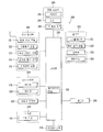
도 13은 본 명세서에 개시된 일 실시 예에 따른 무선 충전 시스템의 동작 제어 과정을 나타내는 흐름도이다.
도 14a 내지 도 14c는 본 명세서에 개시된 일 실시 예에 따른 무선 충전 시스템의 동작 제어 과정을 나타내는 개념도이다.
도 15는 본 명세서에 개시된 다른 일 실시 예에 따른 무선 충전 시스템의 동작 제어 과정을 나타내는 흐름도이다.
도 16a 내지 도 16f는 본 명세서에 개시된 다른 일 실시 예에 따른 무선 충전 시스템의 동작 제어 과정을 나타내는 개념도이다.
도 17은 본 명세서에 개시된 실시예들에 따른 무선 충전 서비스 영역을 설명하기 위한 개념도이다.
도 18은 본 명세서에 개시된 또 다른 일 실시예에 따른 무선 충전 시스템을 나타내는 개념도이다.
도 19는 본 명세서에 개시된 또 다른 일 실시예에 따른 전자기기(200)의 전력 정보를 나타내는 개념도이다.
도 20 본 명세서에 개시된 또 다른 일 실시예에 따른 무선 충전 시스템의 동작 제어 과정을 나타내는 흐름도이다.1 is an exemplary view conceptually showing a wireless charger and an electronic device according to the embodiments disclosed herein.
2A and 2B are block diagrams exemplarily showing configurations of an electromagnetic
Figs. 3A and 3B are block diagrams exemplarily showing configurations of the
4 is a perspective view exemplarily showing a charger for charging a plurality of electronic devices according to the first embodiment disclosed herein.
5 is a perspective view of a charger having a folded structure for charging a plurality of electronic devices according to an aspect of the second embodiment disclosed herein.
6 is a perspective view of a charger having a folded structure for charging a plurality of electronic devices according to another embodiment of the second disclosed embodiment.
7 is a perspective view of a charger having a folded structure for charging a plurality of electronic devices according to another embodiment of the second embodiment disclosed herein.
8 is a perspective view of a charger having a slide-type structure for charging a plurality of electronic apparatuses according to a third embodiment of the present invention.
FIG. 9 is a block diagram showing a charger further including an additional configuration in addition to the configuration shown in FIGS. 2 to 3. FIG.
10 is a block diagram showing a configuration in which the
11 is a block diagram showing a configuration in which the
12A is a conceptual diagram illustrating a wireless charging system in accordance with one embodiment disclosed herein.
12B is a conceptual diagram illustrating a wireless charging system in accordance with another embodiment disclosed herein.
13 is a flowchart illustrating an operation control process of the wireless charging system according to an embodiment disclosed herein.
14A to 14C are conceptual diagrams illustrating a process of controlling the operation of the wireless charging system according to the embodiment disclosed herein.
15 is a flowchart illustrating an operation control process of the wireless charging system according to another embodiment disclosed herein.
16A to 16F are conceptual diagrams illustrating a process of controlling the operation of the wireless charging system according to another embodiment disclosed herein.
17 is a conceptual diagram for explaining a wireless charging service area according to the embodiments disclosed herein.
18 is a conceptual diagram illustrating a wireless charging system in accordance with another embodiment disclosed herein.
19 is a conceptual diagram illustrating power information of the
20 is a flowchart illustrating an operation control process of the wireless charging system according to another embodiment disclosed herein.
본 명세서에서 사용되는 기술적 용어는 단지 특정한 실시 예를 설명하기 위해 사용된 것으로, 본 발명을 한정하려는 의도가 아님을 유의해야 한다. 또한, 본 명세서에서 사용되는 기술적 용어는 본 명세서에서 특별히 다른 의미로 정의되지 않는 한, 본 발명이 속하는 기술 분야에서 통상의 지식을 가진 자에 의해 일반적으로 이해되는 의미로 해석되어야 하며, 과도하게 포괄적인 의미로 해석되거나, 과도하게 축소된 의미로 해석되지 않아야 한다. 또한, 본 명세서에서 사용되는 기술적인 용어가 본 발명의 사상을 정확하게 표현하지 못하는 잘못된 기술적 용어일 때에는, 당업자가 올바르게 이해할 수 있는 기술적 용어로 대체되어 이해되어야 할 것이다. 또한, 본 발명에서 사용되는 일반적인 용어는 사전에 정의되어 있는 바에 따라, 또는 전후 문맥상에 따라 해석되어야 하며, 과도하게 축소된 의미로 해석되지 않아야 한다.It is noted that the technical terms used herein are used only to describe specific embodiments and are not intended to limit the invention. It is also to be understood that the technical terms used herein are to be interpreted in a sense generally understood by a person skilled in the art to which the present invention belongs, Should not be construed to mean, or be interpreted in an excessively reduced sense. Further, when a technical term used herein is an erroneous technical term that does not accurately express the spirit of the present invention, it should be understood that technical terms that can be understood by a person skilled in the art are replaced. In addition, the general terms used in the present invention should be interpreted according to a predefined or prior context, and should not be construed as being excessively reduced.
또한, 본 명세서에서 사용되는 단수의 표현은 문맥상 명백하게 다르게 뜻하지 않는 한, 복수의 표현을 포함한다. 본 출원에서, "구성된다" 또는 "포함한다" 등의 용어는 명세서 상에 기재된 여러 구성 요소들, 또는 여러 단계들을 반드시 모두 포함하는 것으로 해석되지 않아야 하며, 그 중 일부 구성 요소들 또는 일부 단계들은 포함되지 않을 수도 있고, 또는 추가적인 구성 요소 또는 단계들을 더 포함할 수 있는 것으로 해석되어야 한다.Also, the singular forms "as used herein include plural referents unless the context clearly dictates otherwise. In the present application, the term "comprising" or "comprising" or the like should not be construed as necessarily including the various elements or steps described in the specification, Or may be further comprised of additional components or steps.
또한, 또한, 본 명세서에서 사용되는 구성요소에 대한 접미사 "모듈" 및 "부"는 명세서 작성의 용이함만이 고려되어 부여되거나 혼용되는 것으로서, 그 자체로 서로 구별되는 의미 또는 역할을 갖는 것은 아니다.Furthermore, suffixes "module" and " part "for components used in the present specification are given or mixed in consideration of ease of specification, and do not have their own meaning or role.
본 명세서에서 설명되는 전자 기기는 휴대가 가능한 모든 전자 기기, 예컨대 휴대폰, 셀룰러폰, 스마트 폰(smart phone), PDA(Personal Digital Assistants), PMP(Portable Multimedia Player)와, 태블릿, 혹은 멀티미디어 기기 등을 포괄하는 의미로 해석되어야 한다.The electronic device described in this specification can be applied to all portable electronic devices such as a mobile phone, a cellular phone, a smart phone, a PDA (Personal Digital Assistants), a portable multimedia player (PMP), a tablet, And should be interpreted in its entirety.
그러나, 본 명세서에 기재된 실시 예에 따른 구성은 단말에만 적용 가능한 경우를 제외하면, 디지털 TV, 데스크탑 컴퓨터 등과 같은 고정 단말기에도 적용될 수도 있음을 본 기술분야의 당업자라면 쉽게 알 수 있을 것이다.However, it will be apparent to those skilled in the art that the configuration according to the embodiments described herein may be applied to a fixed terminal such as a digital TV, a desktop computer, and the like, unless the terminal is applicable only to a terminal.
또한, 본 명세서에서 사용되는 제1, 제2 등과 같이 서수를 포함하는 용어는 다양한 구성 요소들을 설명하는데 사용될 수 있지만, 상기 구성 요소들은 상기 용어들에 의해 한정되어서는 안 된다. 상기 용어들은 하나의 구성요소를 다른 구성요소로부터 구별하는 목적으로만 사용된다. 예를 들어, 본 발명의 권리 범위를 벗어나지 않으면서 제1 구성요소는 제2 구성 요소로 명명될 수 있고, 유사하게 제2 구성 요소도 제1 구성 요소로 명명될 수 있다. Furthermore, terms including ordinals such as first, second, etc. used in this specification can be used to describe various elements, but the elements should not be limited by the terms. The terms are used only for the purpose of distinguishing one component from another. For example, without departing from the scope of the present invention, the first component may be referred to as a second component, and similarly, the second component may also be referred to as a first component.
이하, 첨부된 도면을 참조하여 본 발명에 따른 바람직한 실시예를 상세히 설명하되, 도면 부호에 관계없이 동일하거나 유사한 구성 요소는 동일한 참조 번호를 부여하고 이에 대한 중복되는 설명은 생략하기로 한다. Hereinafter, exemplary embodiments of the present invention will be described in detail with reference to the accompanying drawings, wherein like reference numerals refer to like or similar elements throughout the several views, and redundant description thereof will be omitted.
또한, 본 발명을 설명함에 있어서 관련된 공지 기술에 대한 구체적인 설명이 본 발명의 요지를 흐릴 수 있다고 판단되는 경우 그 상세한 설명을 생략한다. 또한, 첨부된 도면은 본 발명의 사상을 쉽게 이해할 수 있도록 하기 위한 것일 뿐, 첨부된 도면에 의해 본 발명의 사상이 제한되는 것으로 해석되어서는 아니 됨을 유의해야 한다.In the following description, well-known functions or constructions are not described in detail since they would obscure the invention in unnecessary detail. It is to be noted that the accompanying drawings are only for the purpose of facilitating understanding of the present invention, and should not be construed as limiting the scope of the present invention with reference to the accompanying drawings.
도 1은 본 명세서에 개시된 실시예들에 따른 무선 충전기 및 전자 기기를 개념적으로 나타낸 예시도이다.1 is an exemplary view conceptually showing a wireless charger and an electronic device according to the embodiments disclosed herein.
도 1을 참조하여 알 수 있는 바와 같이, 전자 기기(200)는 무선 충전이 가능한 기기로, 상기 충전기(100)로부터 무선 전력을 수신하여 배터리를 충전할 수 있다.As shown in FIG. 1, the
상기 충전기(100)는 전자기 유도 현상을 이용한 전자기 유도 방식과 특정 주파수에 전력을 실어 보내는 자기 공명 방식 중 하나 이상을 이용할 수 있다.The
유도방식에 의한 무선 충전은 1차 코일 및 2차 코일을 이용하여 전력을 무선으로 전송하는 기술로, 하나의 코일에서 다른 코일 쪽으로 자기장을 통해 전류를 유도하는 전자기 유도 방식의 원리를 이용하는 무선 충전을 말한다.Wireless charging by induction method is a technology to transmit power wirelessly using primary and secondary coils. It uses wireless induction principle that induces current through one magnetic field from one coil to another. It says.
자기 공명 방식에 의한 충전은 충전기의 공진 주파수와 전자 기기에서의 공진 주파수를 일치시켜, 에너지가 충전기에서 전자 기기로 전달될 수 있게 한다. Charging by the magnetic resonance method matches the resonance frequency of the charger with the resonance frequency of the electronic device, so that energy can be transferred from the charger to the electronic device.
한편, 상기 전자 기기(200) 및 충전기(100)는 일정한 거리(d)에 의해 분리될 수 있다. 이와 같이 상기 충전기(100)와 상기 전자 기기(200)는 접점되지 않고, 일정한 거리(d)만큼 서로 떨어져 있을 수 있기 때문에, 종래 기술과 달리 동시에 여러 전자 기기를 충전할 수 있다.Meanwhile, the
이하에서는 전자기 유도 방식을 이용하는 경우, 충전기와 전자 기기의 구성에 대해서 설명하기로 한다. Hereinafter, the configuration of the charger and the electronic device in the case of using the electromagnetic induction method will be described.
도 2A 및 도 2B는 본 명세서에 개시된 실시 예들에서 채용 가능한 전자기 유도 방식의 충전기(100) 및 전자 기기(200)의 구성을 예시적으로 나타낸 블록도이다.2A and 2B are block diagrams exemplarily showing configurations of an electromagnetic
먼저, 도 2A를 참조하면, 상기 충전기(100)는 유도전류를 이용하여 전자 기기(200)의 배터리를 충전할 수 있다. 상기 전자 기기(200)는 후술하는 바와 같이 이동 통신 단말기(예컨대 휴대폰, 셀룰러폰) 또는 멀티미디어 기기일 수 있다. 상기 전자 기기가 이동단말기일 경우에는 도 10을 참조하여 후술하기로 한다.Referring to FIG. 2A, the
상기 충전기(100)는 전자 기기(200)의 배터리를 무선 충전하기 위한 장치로, 상기 배터리 충전에 필요한 전력을 송신하는 전력송신기이다. The
상기 충전기(100)는 전자기 유도 방식의 충전부(110)를 포함할 수 있다. 상기 전자기 유도 방식의 충전부(110)는 1차코일(111), 센서(112), 스위칭부(113), 비교부(114), 충전 제어부(115), 출력부(116)을 포함한다.The
상기 1차코일(111)은 전원이 인가되면 전자기장을 발생시킨다. 상기 1차코일(111)은 솔레노이드로 구현될 수 있다. 또한, 상기 1차코일(111)에서 발생되는 전자기장은 전자 기기(200)의 2차코일(2931)에 자기장을 유도하여 2차코일(2931)에 유도 전류를 발생시킬 수 있다.The
센서(112)는 충전기(100) 위에 전자 기기(200)가 올려지면 전자 기기(200)의 접촉을 감지하고, 충전기(100) 상에 전자 기기(200)의 위치를 확인한다.The
또한, 상기 센서(112)는 상기 전자 기기(200)가 충전기(100) 위에 놓이면 충전효율이 가장 높은 위치에 배치될 수 있도록 도와주는 역할을 한다. 충전기(100) 위에 전자 기기(200)가 놓였을 때, 1차코일(111)의 중심과 상기 2차코일(2931)의 중심이 일직선상에 위치해야 충전효율이 가장 높다.In addition, the
따라서, 상기 충전기(100)의 1차코일(111)과 상기 전자 기기(200)의 2차코일(2931)의 중심이 일직선상에 위치하도록 하기 위해, 1차코일(111)의 중심에 자석을 설치하여 2차코일(2931)의 중심이 1차코일(111)의 중심을 기준으로 소정 반경 내에 들어오면 자력으로 전자 기기를 끌어당겨 1차코일(111)과 2차코일(2931)의 중심이 일직선상에 위치하게 할 수 있다.Therefore, in order for the center of the
여기서, 1차코일(111)과 2차코일(2931)의 중심간의 거리가 허용오차 범위 D를 벗어나면, 충전기(100)는 전자 기기(200)가 정렬조건을 만족하지 않는 것으로 인식하여 무선 충전이 불가능함을 알리는 신호를 전자 기기(200)로 전송할 수 있다.If the distance between the center of the
즉, 충전기(100)는 1차코일(111)과 2차코일(2931)의 중심이 중첩될 때 상기 1차코일(111)과 2차코일(2931)의 중심간의 거리가 정렬조건을 만족하지 않으면 전자 기기(200)의 배터리 무선충전을 허가하지 않는다. 이때, 충전기(100)는 전자 기기(200)의 2차코일(2931)의 중심이 1차코일(111)의 중심을 기준으로 벗어난 방향 및 거리에 대한 정보를 전자 기기(200)로 전송할 수 있다.That is, when the centers of the
스위칭부(113)는 상기 충전 제어부(115)의 제어에 따라 외부에서 공급되는 전원을 상기 1차코일(111)로 공급하거나 차단하는 역할을 수행한다.The
상기 비교부(114)는 충전기(100)의 정상동작 여부를 확인하기 위한 것으로, 외부로부터 공급되는 전원의 전압 또는 전류를 검출하고, 상기 검출된 전압 또는 전류가 임계값을 초과하는지를 확인한다. 상기 비교부(114)는 외부로부터 공급되는 전원의 전압 또는 전류를 검출하기 위한 저항과 상기 검출된 전원의 전압값 또는 전류값과 임계값을 비교하여 그 비교결과를 출력하는 비교기를 포함한다. The
예를 들어, 비교부(114)는 외부로부터 인가되는 전원이 5V를 초과하는지를 확인하여 그 확인결과를 충전 제어부(115)로 출력한다. 상기 충전 제어부(115)는 상기 외부로부터 인가되는 전원이 5V를 초과하면 상기 스위칭부(113)를 제어하여 2차코일(2931)로 인가되는 전원을 차단한다.For example, the
상기 충전 제어부(115)는 상기 비교부(114)로부터 전송받은 확인결과에 따라 상기 스위칭부(113)를 제어한다. 또한, 충전 제어부(115)는 상기 전자 기기(200)와 통신을 수행하며, 그 통신을 통해 배터리의 충전상태를 확인할 수 있다. 예를 들어, 상기 충전 제어부(115)는 블루투스와 같은 근거리 통신을 통해 전자 기기(200)와 통신을 수행하므로 배터리(216)의 충전상태를 확인할 수 있다.The
또한, 상기 충전기(100)는 복수 개의 전자 기기들을 동시에 충전할 수 있다. Also, the
다시 말해서, 충전기(100) 상에 2개 이상의 전자 기기들을 올려놓고 충전이 가능하며, 전자 기기들은 서로 다른 기종일 수도 있다. 예를 들어, 충전기(100)에 휴대폰과 멀티미디어 플레이어, PDA 등을 동시에 올려놓고 무선 충전을 할 수 있다.In other words, it is possible to charge two or more electronic devices on the
상기 출력부(116)는 상기 충전 제어부(115)의 제어에 따라 충전상태를 표시한다. 상기 출력부(116)는 발광소자 및/또는 LCD 등으로 구현될 수 있다.The
한편, 도 2B를 참조하면, 전자 기기(200)는 전원 공급부(290)를 포함한다. 상기 전원 공급부(290)는 배터리(291), 충전부(292), 무선 전력 수신부(293)를 포함한다. Referring to FIG. 2B, the
상기 무선 전력 수신부(293)는 충전기(100)에서 발생하는 유도전류를 수신하는 역할을 한다.The wireless
상기 무선 전력 수신부(293)는 2차코일(2931), 정류기(2932), 컨버터(2933) 및 통신제어부(2934)를 포함한다.The wireless
상기 2차코일(2931)은 충전기(100)의 1차코일(111)에서 발생되는 전자기장의 변화에 따라 유도전류를 생성한다. 즉, 상기 2차코일(2931)은 상기 충전기(100)의 1차코일(111)에서 발생하는 유도전류를 수신하여 유도전류를 발생시킨다.The
상기 정류기(2932)는 상기 2차코일(2931)을 통해 수신되는 유도전류를 직류전원(직류전압 또는 직류전원)으로 변환하는 교류-직류 변환기이다.The
상기 컨버터(2933)는 상기 정류기(2932)에서 출력되는 직류전원을 소정의 전압으로 변환한다. 즉, 컨버터(2933)는 배터리 충전을 위한 적정한 전압으로 상기 직류전원을 변환하는 역할을 한다. 예를 들어, 상기 정류기(2932)를 통해 출력되는 직류전원이 9V이면 컨버터(2933)는 9V를 5V로 변환한다.The
상기 통신제어부(2934)는 충전기(100)와 통신을 수행한다. 상기 통신제어부(2934)는 해당 전자기기가 충전이 가능한 기기인지 상기 충전기(100)에 인증을 요청할 수 있다. 상기 인증 요청시 상기 통신제어부(2934)는 배터리의 장치번호 등과 같은 식별정보를 충전기(100)로 전송한다.The
상기 충전부(292)는 2차코일(2931)을 통해 수신되는 유도전류를 이용하여 배터리(291)를 충전한다. 다시 말해서, 상기 충전부(292)는 충전패드에서 발생되는 전자기장 유도현상에 의해 2차코일(2931)이 생성하는 유도전류를 배터리(292)로 공급한다. 상기 충전부(292)는 배터리 충전을 제어하는 충전회로, 과전류 및 과전압를 방지하기 위한 과전류/과전압 보호회로를 포함할 수 있다.The charging
한편, 이하에서는 도 3을 참조하여 자기 공명 방식에 의한 충전기 및 전자 기기의 구성을 살펴보기로 한다.Hereinafter, the configuration of a charger and an electronic device according to a magnetic resonance method will be described with reference to FIG.
도 3A 및 도 3B는 본 명세서에 개시된 실시 예들에서 채용 가능한 자기 공명 방식의 충전기(100) 및 전자 기기(200)의 구성을 예시적으로 나타낸 블록도이다.3A and 3B are block diagrams exemplarily showing configurations of a
먼저, 공명(resonance)에 대해 간략하게 설명하면 다음과 같다.First, the resonance will be briefly described as follows.
공명(resonance)이란, 진동계가 그 고유진동수와 같은 진동수를 가진 외력을 주기적으로 받아 진폭이 뚜렷하게 증가하는 현상을 말한다. 공명은 역학적 진동 및 전기적 진동 등 모든 진동에서 일어나는 현상인데, 이중에서 전기적 공명일 때는 공진이라고도 한다. 일반적으로 외부에서 진동계에 진동시킬 수 있는 힘을 가했을 때 그 고유진동수와 외부에서 가해주는 힘의 진동수가 같으면 그 진동은 심해지고 진폭도 커진다.Resonance refers to a phenomenon in which the vibration system receives an external force having the same frequency as its natural frequency periodically, and the amplitude increases sharply. Resonance is a phenomenon that occurs in all vibrations, such as mechanical vibration and electrical vibration. In electrical resonance, it is also called resonance. Generally, when a force that can vibrate the vibration system is externally applied, if the natural frequency and the force externally applied are the same, the vibration becomes larger and the amplitude becomes larger.
같은 원리로, 일정 거리 내에서 떨어져 있는 복수의 진동체들이 서로 동일한 주파수로 진동하는 경우, 상기 복수의 진동체들은 상호 공명하며, 이 경우 상기 복수의 진동체들 간에는 저항이 감소하게 된다. 전기회로에서는 코일과 콘덴서를 사용하여 공진기를 만들 수 있다. 공진기는 공명기와 같은 의미로 사용될 때가 많으나, 보통은 전자파 또는 전기진동에 대한 것을 말한다. 전기회로에서는 안테나로 수신한 전파 속에서 특정 주파수를 선택하기 위한 회로로 공진기를 이용할 수도 있다.In the same principle, when a plurality of vibrating bodies spaced within a certain distance oscillate at the same frequency, the plurality of vibrating bodies resonate with each other, and in this case, the resistance between the vibrating bodies decreases. In an electric circuit, a resonator can be made using a coil and a capacitor. A resonator is often used in the same sense as a resonator, but usually refers to electromagnetic waves or electric vibrations. In an electric circuit, a resonator may be used as a circuit for selecting a specific frequency in an electric wave received by an antenna.
따라서, 도 3A 및 도 3B에 도시된 상기 전자 기기(200)는 상기 충전기(100)에서 발생하는 평면파 방사의 커플링을 이용하여 배터리를 충전할 수 있다Therefore, the
구체적으로, 도 3A를 참조하여 알 수 있는 바와 같이, 충전기(100)는 자기 공명 방식의 충전부(120)를 포함할 수 있다. 상기 자기 공명 방식의 충전부(120)는 송신 안테나(121), 센서(122), 매칭부(123), 오실레이터(124) 및 충전 제어부(125)를 포함한다. 또한, 충전기(100)는 출력부(126)를 더 포함할 수도 있다.Specifically, as can be seen with reference to FIG. 3A, the
상기 송신 안테나(121)는 수신 안테나와 동일한 주파수 또는 동일한 주파수 근방에서 공진하도록 동조된다. The
상기 센서(122)는 송신 안테나에 의해 생성된 근접장의 근방에서 활성 수신기들의 존재 또는 부존재를 검출할 수 있다. 예로서, 센서는, 송신 안테나에 의해 생성된 근접장의 근방에서의 활성 수신기들의 존재 또는 부존재에 의해 영향을 받는 전류를 모니터링한다. 이 검출은, 전자 기기(200)와 통신하도록 에너지를 송신하기 위해 오실레이터를 인에이블시킬 지를 판정할 시에 사용하기 위하여 제어부(125)에 의해 모니터링된다.The
상기 매칭부(123)는 오실레이터에 의해 결정된 바와 같은 RF 신호를 유도하고, 전자 기기(200)에 커플링된 디바이스들의 자체-재밍을 방지하기 위한 레벨로 하모닉 방출을 감소시키며, 임피던스(예를 들어, 50옴)를 송신 안테나에 매칭시킨다.The
상기 오실레이터(124)는 원하는 주파수에서 생성하도록 구성되며, 조정 신호에 응답하여 조정될 수도 있다.The
제어부(125)는 송신 페이즈 동안 오실레이터를 인에이블시키고, 오실레이터의 주파수를 조정하며, 이웃한 디바이스들과 상호작용하기 위한 통신 프로토콜을 구현하기 위해 출력 전력 레벨을 조정한다.The
출력부(126)는 상기 충전 제어부의 제어에 따라 충전상태를 표시한다. 상기 출력부는 발광소자 및/또는 LCD 등으로 구현될 수 있다.The
한편, 도 3B를 참조하면, 전자 기기(200)는 전원 공급부(290)를 포함한다. 상기 전원 공급부(290)는 배터리(291), 충전부(292), 무선 전력 수신부(293)를 포함한다. Referring to FIG. 3B, the
상기 무선 전력 수신부(293)는 수신 안테나(2931’), 정류기(2932), 컨버터(2933), 통신제어부(2934)를 포함한다. The wireless
상기 수신 안테나(2931’)는 상기 충전기(100)의 송신 안테나와 동일한 주파수 또는 동일한 주파수 근방에서 공진하도록 동조된다. The receiving antenna 2931 'is tuned to resonate at the same frequency or near the same frequency as the transmitting antenna of the
상기 정류기(2932)는 수신 안테나(2931’)에서 수신된 RF 에너지 신호를 비-교류 전력으로 정류한다. 그리고, 상기 컨버터(2933)는 전자 기기(200)와 호환 가능한 에너지 전위(예를 들어, 전압)로 그 정류된 RF 에너지 신호를 변환시킨다.The
상기 통신제어부(2934)는 충전기(100)와 통신을 수행한다. 상기 통신제어부(2934)는 해당 전자기기가 충전이 가능한 기기인지 상기 충전기(100)에 인증을 요청할 수 있다. 상기 인증 요청시 상기 통신제어부(2934)는 배터리의 장치번호 등과 같은 식별정보를 충전기(100)로 전송한다.The
상기 충전부(292)는 수신 안테나(2931’)를 통해 수신된 RF 에너지 신호를 이용하여 배터리(291)를 충전한다. 다시 말해서, 충전부(292)는 충전기(100)에서 전송되는 RF 에너지 신호를 전자 기기(200)에서 사용 가능한 형태로 변환하여 배터리(291)로 공급한다. 상기 충전부(292)는 배터리 충전을 제어하는 충전회로, 과전류 및 과전압을 방지하기 위한 과전류/과전압 보호회로를 더 포함할 수 있다.The charging
한편, 이하에서는 상기 충전기의 외형 구조에 대해서 도 4를 참조하여 설명하기로 한다.Hereinafter, the external structure of the charger will be described with reference to FIG.
도 4는 본 명세서에 개시된 제1 실시 예에 따라 다수의 전자 기기를 충전하기 위한 충전기를 예시적으로 나타낸 사시도이다.4 is a perspective view exemplarily showing a charger for charging a plurality of electronic devices according to the first embodiment disclosed herein.
도 4(a)를 참조하여 알 수 있는 바와 같이, 다수의 전자 기기를 충전하기 위한 충전기(100)는 패드 형태일 수 있다. As can be seen from FIG. 4 (a), the
그리고, 상기 패드 형태의 충전기는 도시된 바와 같이 바디 윗면이 단이 지게 형성될 수 있다. 단진 부분 중 낮은 부분의 바디는 상기 전자 기기(200)가 놓여지게 된다. 그리고, 상기 낮은 부분의 바디 내부에는 전술한 바와 같이, 상기 전자기 유도 방식의 충전부(110) 또는 상기 자기 공명 방식의 충전부(120)를 수용하여, 외부로부터의 충격 또는 이물질이 접촉되는 것을 보호할 수 있다.As shown in the figure, the pad-type charger may have a body upper surface. The body of the lower part of the vibration reducing part is placed on the
상기 낮은 부분의 바디 상면은 상기 전자 기기와 전기가 도통되어 쇼트가 되는 것을 방지하기 위해 절연 물질, 예컨대 플라스틱으로 이루어질 수 있다. 또는 절연 물질이 코팅될 수 있다.The upper surface of the body of the lower part may be made of an insulating material, for example, plastic, in order to prevent electricity from being electrically conducted to the electronic apparatus. Or an insulating material may be coated.
상기 낮은 부분에는 상기 전자 기기가 놓여졌을 때 상기 윗면에서 이탈되지 않도록, 가이드 부재가 설치될 수 있다. 상기 가이드 부재는 상기 충전기의 상면 테두리를 따라서 설치될 수도 있고, 혹은 상기 충전기의 상면 테두리 일부에 다수 개수가 형성될 수 있다.A guide member may be provided on the lower portion so as not to be detached from the upper surface when the electronic apparatus is placed. The guide member may be provided along an upper surface of the charger, or a plurality of the guide members may be formed on a part of an upper surface of the charger.
상기 단진 부분 중 높은 부분에는 디스플레이부(130)가 장착될 수 있다. 이때, 상기 디스플레이부(130)의 정면이 지면과 수평되지 않도록 상기 단이 진 부분은 경사를 가질 수 있다. 다시 말해서, 상기 디스플레이부(130)의 정면이 지면과 수평되도록 설치되는 경우에는 사용자의 시인성이 문제가 될 수 있으므로, 상기 디스플레이부(130)는 경사를 갖게 설치되는 것이 바람직하다. 이를 위해, 상기 단진 부분 중 높은 부분은 낮은 부분 방향으로 경사지도록 형성될 수도 있다.A
또한, 상기 패드 형태의 충전기 상면에는 다수의 홀이 형성될 수 있고, 상기 다수의 홀의 내측에는 오디오 출력부(140)가 장착되어, 상기 오디오 출력부(140)에서 발생되는 음향이 상기 다수 개의 홀을 통해 외부로 출력될 수 있다.In addition, a plurality of holes may be formed on the upper surface of the pad type charger, and an
대안적으로, 상기 다수개의 홀은 상기 패드 형태의 충전기 측면에 형성될 수 있고, 상기 측면에 형성되는 다수 개의 홀 내측에 상기 오디오 출력부(140)가 장착될 수 있다. Alternatively, the plurality of holes may be formed on the side surface of the pad-shaped charger, and the
또한, 상기 패드 형태의 충전기 상면에는 전술한 출력부(116 또는 126)가 장착될 수 있다. 상기 출력부(116)는 전술한 바와 같이 발광소자일 수 있고, 충전 상태에 따라서 점멸되거나 점등될 수 있다. 또는 충전 상태에 따라서 다른 색상의 빛을 낼 수 있다.In addition, the above-described
또한, 도시되지는 않았으나, 상기 패드 형태의 충전기 측면에는 열을 교환하기 위한 다수개의 홀이 형성될 수도 있다. 또한, 상기 다수 개의 홀은 상기 패드 형태의 상면에도 형성될 수 있다. 또한, 도시되지는 않았으나, 상기 패드 형태의 충전기 저면에는 지면과 마찰력을 갖게 하여, 지면으로부터 쉽게 미끄러지지 않게 하기 위한 지지 부재가 설치될 수 있다. 상기 지지 부재는 고무 재질로 이루어질 수 있다.Also, although not shown, a plurality of holes for exchanging heat may be formed on the side surface of the pad-shaped charger. Also, the plurality of holes may be formed on the pad-shaped upper surface. Also, although not shown, a support member may be provided on the bottom surface of the pad-shaped charger so as to have frictional force with the ground, so as not to slip easily from the ground. The support member may be made of a rubber material.
한편, 도 4(b)에 도시된 바와 같이, 상기 패드 형태의 충전기(100)는 적어도 2개 이상의 전자 기기들을 동시에 충전할 수 있도록, 2개 이상의 전자 기기들의 폭을 합한 것 보다 넓은 폭을 갖게 형성될 수 있다. 4 (b), the pad-
도 5는 본 명세서에 개시된 제2 실시 예의 일 태양에 따라 다수의 전자 기기를 충전하기 위해 접이형 구조를 갖는 충전기의 사시도이고, 도 6은 본 명세서에 개시된 제2 실시예의 다른 태양예 따라 다수의 전자 기기를 충전하기 위해 접이형 구조를 갖는 충전기의 사시도이다.FIG. 5 is a perspective view of a charger having a junction structure for charging a plurality of electronic devices according to an embodiment of the second disclosed embodiment, and FIG. 6 is a perspective view of a plurality of electronic devices according to another embodiment of the second embodiment disclosed herein Fig. 3 is a perspective view of a charger having a folding structure for charging an electronic device. Fig.
도 5 및 도 6을 참조하여 알 수 있는 바와 같이, 상기 충전기는 접이 형태일 수 있다. As can be seen with reference to Figures 5 and 6, the charger may be in the form of a fold.
구체적으로, 도 5(a)를 참조하여 알 수 있는 바와 같이, 충전기의 메인 바디는 힌지 결합되는 덮개형 바디(170)에 의해서 덮혀질 수 있다. 도 5에서는 상기 메인 바디와 덮개 바디(170)의 측면에 힌지 체결 구조가 형성되어, 책(book)과 같이 상기 덮개 바디(170)가 열려지거나 혹은 덮혀지는 것으로 나타내었다. 5 (a), the main body of the charger can be covered by the hinged cover-
그리고, 상기 충전기(100)의 메인 바디 상면은 단이 지게 형성될 수 있다.The upper surface of the main body of the
상기 메인 바디의 내부에는, 상기 전자기 유도 방식의 충전부(110) 또는 상기 자기 공명 방식의 충전부(120)를 수용할 수 있다.In the main body, the electromagnetic induction
상기 덮개형 바디(170)의 상면은 상기 전자 기기와 전기가 도통되어 쇼트가 되는 것을 방지하기 위해 절연 물질, 예컨대 플라스틱으로 이루어질 수 있다. 또는 절연 물질이 코팅될 수 있다.The upper surface of the
상기 덮개형 바디(170)의 상면에는 상기 전자 기기(200)가 놓여졌을 때 상기 상면에서 미끄러져 이탈되지 않도록, 가이드 부재가 설치될 수 있다. 상기 가이드 부재는 상기 충전기의 상면 테두리를 따라서 설치될 수도 있고, 혹은 상기 충전기의 상면 테두리 일부에 다수 개수가 설치될 수 있다.A guide member may be installed on the upper surface of the
상기 덮개형 바디(170)는 상기 메인 바디와는 별도로 상기 전자기 유도 방식의 충전부(110) 또는 상기 자기 공명 방식의 충전부(120)를 추가적으로 수용할 수 있다. 이때, 상기 메인 바디와 상기 덮개형 바디(170)는 서로 동일한 방식의 충전부를 수용할 수도 있고, 혹은 서로 다른 방식의 충전부를 수용할 수도 있다.The cover-
상기 덮개형 바디(170)에 의해서 상기 메인 바디가 덮혀질 경우, 상기 메인 바디 내에 수용된 충전부(110 또는 120)는 동작되지 않도록 제어될 수 있다. 이를 위해, 상기 덮개형 바디의 내측 또는 상기 메인 바디의 상면에는 덮힘과 열림을 감지하기 위한 센서 혹은 덮힘/열림에 의해 on/off되는 스위치가 장착될 수 있다.When the main body is covered by the
한편, 도 5(b)와 같이, 상기 덮개형 바디(170)는 펼쳐져게 되면, 상기 충전기의 메인 바디와 나란하게 될 수 있다. 상기 덮개형 바디(170)의 내측면에는 상기 전자 기기(200)가 올려질 수 있도록 평평하게 형성될 수 있다. 또한, 상기 덮개형 바디(170)의 내측면에는 상기 전자 기기(200)가 놓여졌을 때 상기 상면에서 미끄러져 이탈되지 않도록, 가이드 부재가 설치될 수 있다Meanwhile, as shown in FIG. 5 (b), when the
상기 덮개형 바디(170)는 펼쳐져게 되면, 전술한 센서 또는 스위치에 의해 상기 메인 바디 내에 수용된 충전부(110 또는 120)가 동작하게 된다. 상기 메인 바디 내에 수용된 충전부(110 또는 120)가 동작하게 되면, 상기 충전부(110 또는 120)내의 센서(112 또는 122)가 상기 충전기(100)의 메인 바디 위에 전자 기기(200) 올려져 있는 지를 감지하게 된다. 그리고, 상기 전자 기기(200)가 올려짐을 감지하게 되면, 상기 메인 바디 내의 수용된 충전부(110 또는 120)는 충전을 시작하게 된다.When the cover-
한편, 도 6(a) 및 도 6(b)를 참조하여 알 수 있는 바와 같이, 상기 메인 바디와 덮개 바디(170)의 하단부에 힌지 체결 구조가 형성될 수 있다. 이는, 폭이 좁은 테이블 위에서 공간적으로 효율을 높이기 위한 구조이다. 즉, 상기 덮개 바디(170)가 열려지더라도 장방향으로만 길어지므로, 폭이 좁은 테이블 위에서도 공간 효율이 높아질 수 있다.6 (a) and 6 (b), a hinge fastening structure may be formed at the lower end of the main body and the
도 7는 본 명세서에 개시된 제2 실시예의 또 다른 태양예 따라 다수의 전자 기기를 충전하기 위해 접이형 구조를 갖는 충전기의 사시도이다.7 is a perspective view of a charger having a junction structure for charging a plurality of electronic devices according to another embodiment of the second embodiment disclosed herein.
도 7을 참조하여 알 수 있는 바와 같이, 충전기(100)의 메인 바디에 복수의 덮개형 바디(171, 172)가 힌지 결합될 수 있다. 각각의 덮개형 바디(171, 172)는 전술한 바와 같이 상기 전자기 유도 방식의 충전부(110) 또는 상기 자기 공명 방식의 충전부(120)를 추가적으로 수용할 수 있다. 이와 같이 복수의 덮개형 바디를 구비함으로써, 동시 충전 가능한 전자 기기의 개수를 증대시킬 수 있다. 7, a plurality of lid-
도 8은 본 명세서의 제3 실시예에 따라 다수의 전자 기기를 충전하기 위해 슬라이드형 구조를 갖는 충전기의 사시도이다.8 is a perspective view of a charger having a slide-type structure for charging a plurality of electronic apparatuses according to a third embodiment of the present invention.
도 8(a)에 도시된 바와 같이, 다수의 전자 기기를 충전하기 위한 충전기(100)는 슬라이드 형태일 수 있다. As shown in Fig. 8 (a), the
상기 충전기의 메인 바디의 일 측면에는 슬라이드되는 확장 바디(180)가 수용될 수 있다. 상기 확장 바디(180)는 사용자의 힘 또는 탄성력에 의해 슬라이딩되어 도 8(b)와 같이 외부로 돌출될 수 있다. 도시되지는 않았으나, 상기 확장 바디(180)의 일단에는 걸림부가 형성되어, 상기 확장 바디가 무리한 힘에 의해 당겨지더라도 상기 메인 바디로부터 완전히 이탈되어 분리되는 것을 방지할 수 있다.The
상기 충전기(100)의 메인 바디 상면은 단이 지게 형성될 수 있다.The upper surface of the main body of the
상기 메인 바디의 내부 및 상기 확장 바디는, 상기 전자기 유도 방식의 충전부(110) 또는 상기 자기 공명 방식의 충전부(120)를 수용할 수 있다.The inside of the main body and the extension body can accommodate the electromagnetic induction
또한 상기 메인 바디 및 상기 확장 바디(180)의 상면은 상기 전자 기기와 전기가 도통되어 쇼트가 되는 것을 방지하기 위해 절연 물질, 예컨대 플라스틱으로 이루어질 수 있다. 또는 절연 물질이 코팅될 수 있다.In addition, the main body and the upper surface of the
상기 메인 바디 및 확장 바디(180)의 상면에는 상기 전자 기기(200)가 놓여졌을 때 상기 상면에서 미끄러져 이탈되지 않도록, 가이드 부재가 설치될 수 있다. 상기 가이드 부재는 상기 충전기의 상면 테두리를 따라서 설치될 수도 있고, 혹은 상기 충전기의 상면 테두리 일부에 다수 개수가 설치될 수 있다.A guide member may be installed on the upper surface of the main body and the
도 9는 도 2 내지 도 3에 도시된 구성 외에 추가적인 구성을 더 포함하는 충전기를 나타낸 블록도이다.FIG. 9 is a block diagram showing a charger further including an additional configuration in addition to the configuration shown in FIGS. 2 to 3. FIG.
도 9를 참조하여 알 수 있는 바와 같이, 상기 충전기(100)는 전술한 상기 전자기 유도 방식의 충전부(110) 또는 상기 자기 공명 방식의 충전부(120) 외에, 제어부(160), 디스플레이부(130), 오디오 출력부(140), 통신부(150)를 더 포함할 수 있다.9, the
상기 제어부(160)는 상기 충전부(110 또는 120), 상기 디스플레이부(130), 상기 오디오 출력부(140), 통신부(150)를 제어한다.The
상기 디스플레이부(130)는 액정 디스플레이(liquid crystal display, LCD), 박막 트랜지스터 액정 디스플레이(thin film transistor-liquid crystal display, TFT LCD), 유기 발광 다이오드(organic light-emitting diode, OLED), 플렉시블 디스플레이(flexible display), 3차원 디스플레이(3D display) 중에서 적어도 하나를 포함할 수 있다. The
상기 통신부(150)는 상기 전자 기기(200)와 데이터 통신을 하기 위한, 블루투스TM, 지그비(Zigbee), UWB(Ultra Wide Band), Wireless USB, NFC(Near Field Communication) 중 어느 하나 이상을 위한 전자 부품을 포함할 수 있다.The
한편, 도시되지는 않았으나, 상기 충전기(100)는 마이크를 더 포함할 수 있다. Meanwhile, although not shown, the
그리고, 이하에서는, 상기 전자 기기(200)가 이동통신 단말기일 경우의 구성에 대해서 설명하기로 한다. Hereinafter, the configuration in the case where the
도 10은 본 명세서에 개시된 실시예들에 따른 전자 기기(200)가 이동통신 단말기일 경우의 구성을 나타낸 블록도이다.10 is a block diagram showing a configuration in which the
상기 이동통신 전자기기(200)는 도 2 또는 도 3에 도시된 전원 공급부(290)를 포함한다.The mobile communication
그리고, 상기 전자기기(200)는 무선 통신부(210), A/V(Audio/Video) 입력부(220), 사용자 입력부(230), 센싱부(240), 출력부(250), 메모리(260), 인터페이스부(270), 제어부(280)를 더 포함할 수 있다. 도 10에 도시된 구성요소들이 필수적인 것은 아니어서, 그보다 많은 구성요소들을 갖거나 그보다 적은 구성요소들을 갖는 단말가 구현될 수도 있다.The
이하, 상기 구성요소들에 대해 차례로 살펴본다.Hereinafter, the components will be described in order.
무선 통신부(210)는 전자기기(200)와 무선 통신 시스템 사이, 또는 전자기기(200)와 전자기기(200)가 위치한 네트워크 사이의 무선 통신을 가능하게 하는 하나 이상의 모듈을 포함할 수 있다. 예를 들어, 무선 통신부(210)는 방송 수신 모듈(211), 이동통신 모듈(212), 무선 인터넷 모듈(213), 근거리 통신 모듈(214) 및 위치정보 모듈(215) 등을 포함할 수 있다.The
방송 수신 모듈(211)은 방송 채널을 통하여 외부의 방송 센터로부터 방송 신호 및/또는 방송 관련된 정보를 수신한다.The
상기 방송 채널은 위성 채널 및 지상파 채널을 포함할 수 있다. 상기 방송 센터는, 방송 신호 및/또는 방송 관련 정보를 생성하여 송신하는 서버 또는 기 생성된 방송 신호 및/또는 방송 관련 정보를 제공받아 전자기기(200)에 송신하는 서버를 의미할 수 있다. 상기 방송 신호는, TV 방송 신호, 라디오 방송 신호, 데이터 방송 신호를 포함할 뿐만 아니라, TV 방송 신호 또는 라디오 방송 신호에 데이터 방송 신호가 결합한 형태의 방송 신호도 포함할 수 있다. The broadcast channel may include a satellite channel and a terrestrial channel. The broadcast center may be a server for generating and transmitting broadcast signals and / or broadcast-related information, or a server for receiving broadcast signals and / or broadcast-related information generated in advance and transmitting the broadcast signals and / or broadcast-related information to the
상기 방송 관련 정보는, 방송 채널, 방송 프로그램 또는 방송 서비스 제공자에 관련한 정보를 의미할 수 있다. 상기 방송 관련 정보는, 이동통신망을 통하여도 제공될 수 있다. 이러한 경우에는 상기 이동통신 모듈(212)에 의해 수신될 수 있다.The broadcast-related information may refer to a broadcast channel, a broadcast program, or information related to a broadcast service provider. The broadcast-related information may also be provided through a mobile communication network. In this case, it may be received by the
상기 방송 관련 정보는 다양한 형태로 존재할 수 있다. 예를 들어, DMB(Digital Multimedia Broadcasting)의 EPG(Electronic Program Guide) 또는 DVB-H(Digital Video Broadcast-Handheld)의 ESG(Electronic Service Guide) 등의 형태로 존재할 수 있다.The broadcast-related information may exist in various forms. For example, an EPG (Electronic Program Guide) of DMB (Digital Multimedia Broadcasting) or an ESG (Electronic Service Guide) of Digital Video Broadcast-Handheld (DVB-H).
상기 방송 수신 모듈(211)은, 예를 들어, DMB-T(Digital Multimedia Broadcasting-Terrestrial), DMB-S(Digital Multimedia Broadcasting-Satellite), MediaFLO(Media Forward Link Only), DVB-H(Digital Video Broadcast-Handheld), ISDB-T(Integrated Services Digital Broadcast-Terrestrial) 등의 디지털 방송 시스템을 이용하여 디지털 방송 신호를 수신할 수 있다. 물론, 상기 방송 수신 모듈(211)은, 상술한 디지털 방송 시스템뿐만 아니라 다른 방송 시스템에 적합하도록 구성될 수도 있다.For example, the
방송 수신 모듈(211)을 통해 수신된 방송 신호 및/또는 방송 관련 정보는 메모리(260)에 저장될 수 있다.The broadcast signal and / or broadcast related information received through the
이동통신 모듈(212)은, 이동 통신망 상에서 기지국, 외부의 단말, 서버 중 적어도 하나와 무선 신호를 송수신한다. 상기 무선 신호는, 음성 호 신호, 화상 통화 호 신호 또는 문자/멀티미디어 메시지 송수신에 따른 다양한 형태의 데이터를 포함할 수 있다. The
무선 인터넷 모듈(213)은 무선 인터넷 접속을 위한 모듈을 말하는 것으로, 전자기기(200)에 내장되거나 외장될 수 있다. 무선 인터넷 기술로는 WLAN(Wireless LAN)(Wi-Fi), Wibro(Wireless broadband), Wimax(World Interoperability for Microwave Access), HSDPA(High Speed Downlink Packet Access) 등이 이용될 수 있다. The
근거리 통신 모듈(214)은 근거리 통신을 위한 모듈을 말한다. 무선의 근거리 통신(short range communication) 기술로 블루투스(Bluetooth), RFID(Radio Frequency Identification), 적외선 통신(IrDA, infrared Data Association), UWB(Ultra Wideband), ZigBee 등이 이용될 수 있다. 한편, 유선의 근거리 통신으로는 USB(Universal Serial Bus), IEEE 1394, 인텔사의 썬더볼트 등이 이용될 수 있다.The short
위치정보 모듈(215)은 단말의 위치를 획득하기 위한 모듈로서, 그의 대표적인 예로는 GPS(Global Position System) 모듈이 있다.The
도 10을 참조하면, A/V(Audio/Video) 입력부(220)는 오디오 신호 또는 비디오 신호 입력을 위한 것으로, 이에는 카메라(221)와 마이크(222) 등이 포함될 수 있다. 카메라(221)는 화상 통화모드 또는 촬영 모드에서 이미지 센서에 의해 얻어지는 정지영상 또는 동영상 등의 화상 프레임을 처리한다. 처리된 화상 프레임은 디스플레이부(251)에 표시될 수 있다.Referring to FIG. 10, an A / V (Audio / Video)
카메라(221)에서 처리된 화상 프레임은 메모리(260)에 저장되거나 무선 통신부(210)를 통하여 외부로 전송될 수 있다. 카메라(221)는 사용 환경에 따라 2개 이상이 구비될 수도 있다.The image frame processed by the
마이크(222)는 통화모드 또는 녹음모드, 음성인식 모드 등에서 마이크로폰(Microphone)에 의해 외부의 음향 신호를 입력받아 전기적인 음성 데이터로 처리한다. 처리된 음성 데이터는 통화 모드인 경우 이동통신 모듈(212)을 통하여 이동통신 기지국으로 송신 가능한 형태로 변환되어 출력될 수 있다. 마이크(222)에는 외부의 음향 신호를 입력받는 과정에서 발생되는 잡음(noise)을 제거하기 위한 다양한 잡음 제거 알고리즘이 구현될 수 있다.The
사용자 입력부(230)는 사용자가 전자기기(200)의 동작 제어를 위한 입력 데이터를 발생시킨다. 사용자 입력부(230)는 키 패드(key pad) 돔 스위치 (dome switch), 터치 패드(정압/정전), 조그 휠, 조그 스위치 등으로 구성될 수 있다. The
센싱부(240)는 전자기기(200)의 개폐 상태, 전자기기(200)의 위치, 사용자 접촉 유무, 단말의 방위, 단말의 가속/감속 등과 같이 전자기기(200)의 현 상태를 감지하여 전자기기(200)의 동작을 제어하기 위한 센싱 신호를 발생시킨다. 예를 들어 전자기기(200)가 슬라이드 폰 형태인 경우 슬라이드 폰의 개폐 여부를 센싱할 수 있다. 또한, 전원 공급부(290)의 전원 공급 여부, 인터페이스부(270)의 외부 기기 결합 여부 등을 센싱할 수도 있다. 한편, 상기 센싱부(240)는 근접 센서(241)를 포함할 수 있다. The
출력부(250)는 시각, 청각 또는 촉각 등과 관련된 출력을 발생시키기 위한 것으로, 이에는 디스플레이부(251), 음향 출력 모듈(252), 알람부(253), 및 햅틱 모듈(254) 등이 포함될 수 있다.The
디스플레이부(251)는 전자기기(200)에서 처리되는 정보를 표시(출력)한다. 예를 들어, 단말가 통화 모드인 경우 통화와 관련된 UI(User Interface) 또는 GUI(Graphic User Interface)를 표시한다. 전자기기(200)가 화상 통화 모드 또는 촬영 모드인 경우에는 촬영 또는/및 수신된 영상 또는 UI, GUI를 표시한다. The
디스플레이부(251)는 액정 디스플레이(liquid crystal display, LCD), 박막 트랜지스터 액정 디스플레이(thin film transistor-liquid crystal display, TFT LCD), 유기 발광 다이오드(organic light-emitting diode, OLED), 플렉시블 디스플레이(flexible display), 3차원 디스플레이(3D display) 중에서 적어도 하나를 포함할 수 있다. The
이들 중 일부 디스플레이는 그를 통해 외부를 볼 수 있도록 투명형 또는 광투과형으로 구성될 수 있다. 이는 투명 디스플레이라 호칭될 수 있는데, 상기 투명 디스플레이의 대표적인 예로는 TOLED(Transparant OLED) 등이 있다. 디스플레이부(251)의 후방 구조 또한 광 투과형 구조로 구성될 수 있다. 이러한 구조에 의하여, 사용자는 전자기기 바디의 디스플레이부(251)가 차지하는 영역을 통해 전자기기 바디의 후방에 위치한 사물을 볼 수 있다.Some of these displays may be transparent or light transmissive so that they can be seen through. This can be referred to as a transparent display, and a typical example of the transparent display is TOLED (Transparent OLED) and the like. The rear structure of the
전자기기(200)의 구현 형태에 따라 디스플레이부(251)이 2개 이상 존재할 수 있다. 예를 들어, 전자기기(200)에는 복수의 디스플레이부들이 하나의 면에 이격되거나 일체로 배치될 수 있고, 또한 서로 다른 면에 각각 배치될 수도 있다. There may be two or
디스플레이부(251)와 터치 동작을 감지하는 센서(이하, '터치 센서'라 함)가 상호 레이어 구조를 이루는 경우(이하, '터치 스크린'이라 함)에, 디스플레이부(251)는 출력 장치 이외에 입력 장치로도 사용될 수 있다. 터치 센서는, 예를 들어, 터치 필름, 터치 시트, 터치 패드 등의 형태를 가질 수 있다.(Hereinafter, referred to as a 'touch screen') in which a
터치 센서는 디스플레이부(251)의 특정 부위에 가해진 압력 또는 디스플레이부(251)의 특정 부위에 발생하는 정전 용량 등의 변화를 전기적인 입력신호로 변환하도록 구성될 수 있다. 터치 센서는 터치 되는 위치 및 면적뿐만 아니라, 터치 시의 압력까지도 검출할 수 있도록 구성될 수 있다. The touch sensor may be configured to convert a change in a pressure applied to a specific portion of the
터치 센서에 대한 터치 입력이 있는 경우, 그에 대응하는 신호(들)는 터치 제어기로 보내진다. 터치 제어기는 그 신호(들)를 처리한 다음 대응하는 데이터를 제어부(280)로 전송한다. 이로써, 제어부(280)는 디스플레이부(251)의 어느 영역이 터치 되었는지 여부 등을 알 수 있게 된다.If there is a touch input to the touch sensor, the corresponding signal (s) is sent to the touch controller. The touch controller processes the signal (s) and transmits the corresponding data to the
다시 도 10를 참조하면, 상기 터치스크린에 의해 감싸지는 단말의 내부 영역 또는 상기 터치 스크린의 근처에 근접 센서(241)가 배치될 수 있다. 상기 근접 센서는 소정의 검출면에 접근하는 물체, 혹은 근방에 존재하는 물체의 유무를 전자계의 힘 또는 적외선을 이용하여 기계적 접촉이 없이 검출하는 센서를 말한다. 근접 센서는 접촉식 센서보다는 그 수명이 길며 그 활용도 또한 높다. Referring again to FIG. 10, a
상기 근접 센서의 예로는 투과형 광전 센서, 직접 반사형 광전 센서, 미러 반사형 광전 센서, 고주파 발진형 근접 센서, 정전용량형 근접 센서, 자기형 근접 센서, 적외선 근접 센서 등이 있다. 상기 터치스크린이 정전식인 경우에는 상기 포인터의 근접에 따른 전계의 변화로 상기 포인터의 근접을 검출하도록 구성된다. 이 경우 상기 터치스크린(터치 센서)은 근접 센서로 분류될 수도 있다.Examples of the proximity sensor include a transmission type photoelectric sensor, a direct reflection type photoelectric sensor, a mirror reflection type photoelectric sensor, a high frequency oscillation type proximity sensor, a capacitive proximity sensor, a magnetic proximity sensor, and an infrared proximity sensor. And to detect the proximity of the pointer by the change of the electric field along the proximity of the pointer when the touch screen is electrostatic. In this case, the touch screen (touch sensor) may be classified as a proximity sensor.
이하에서는 설명의 편의를 위해, 상기 터치스크린 상에 포인터가 접촉되지 않으면서 근접되어 상기 포인터가 상기 터치스크린 상에 위치함이 인식되도록 하는 행위를 "근접 터치(proximity touch)"라고 칭하고, 상기 터치스크린 상에 포인터가 실제로 접촉되는 행위를 "접촉 터치(contact touch)"라고 칭한다. 상기 터치스크린 상에서 포인터로 근접 터치가 되는 위치라 함은, 상기 포인터가 근접 터치될 때 상기 포인터가 상기 터치스크린에 대해 수직으로 대응되는 위치를 의미한다.Hereinafter, for convenience of explanation, the act of recognizing that the pointer is positioned on the touch screen while the pointer is not in contact with the touch screen is referred to as "proximity touch & The act of actually touching the pointer on the screen is called "contact touch. &Quot; The position where the pointer is proximately touched on the touch screen means a position where the pointer is vertically corresponding to the touch screen when the pointer is touched.
상기 근접센서는, 근접 터치와, 근접 터치 패턴(예를 들어, 근접 터치 거리, 근접 터치 방향, 근접 터치 속도, 근접 터치 시간, 근접 터치 위치, 근접 터치 이동 상태 등)을 감지한다. 상기 감지된 근접 터치 동작 및 근접 터치 패턴에 상응하는 정보는 터치 스크린상에 출력될 수 있다. The proximity sensor detects a proximity touch and a proximity touch pattern (e.g., a proximity touch distance, a proximity touch direction, a proximity touch speed, a proximity touch time, a proximity touch position, a proximity touch movement state, and the like). Information corresponding to the detected proximity touch operation and the proximity touch pattern may be output on the touch screen.
음향 출력 모듈(252)은 호 신호 수신, 통화모드 또는 녹음 모드, 음성인식 모드, 방송수신 모드 등에서 무선 통신부(210)로부터 수신되거나 메모리(260)에 저장된 오디오 데이터를 출력할 수 있다. 음향 출력 모듈(252)은 전자기기(200)에서 수행되는 기능(예를 들어, 호 신호 수신음, 메시지 수신음 등)과 관련된 음향 신호를 출력하기도 한다. 이러한 음향 출력 모듈(252)에는 리시버(Receiver), 스피커(speaker), 버저(Buzzer) 등이 포함될 수 있다.The
알람부(253)는 전자기기(200)의 이벤트 발생을 알리기 위한 신호를 출력한다. 단말에서 발생 되는 이벤트의 예로는 호 신호 수신, 메시지 수신, 키 신호 입력, 터치 입력 등이 있다. 알람부(253)는 비디오 신호나 오디오 신호 이외에 다른 형태, 예를 들어 진동으로 이벤트 발생을 알리기 위한 신호를 출력할 수도 있다. 상기 비디오 신호나 오디오 신호는 디스플레이부(251)나 음성 출력 모듈(252)을 통해서도 출력될 수 있어서, 그들(251,152)은 알람부(253)의 일부로 분류될 수도 있다.The
햅틱 모듈(haptic module)(254)은 사용자가 느낄 수 있는 다양한 촉각 효과를 발생시킨다. 햅틱 모듈(254)이 발생시키는 촉각 효과의 대표적인 예로는 진동이 있다. 햅택 모듈(254)이 발생하는 진동의 세기와 패턴 등은 제어가능하다. 예를 들어, 서로 다른 진동을 합성하여 출력하거나 순차적으로 출력할 수도 있다. The
햅틱 모듈(254)은, 진동 외에도, 접촉 피부면에 대해 수직 운동하는 핀 배열, 분사구나 흡입구를 통한 공기의 분사력이나 흡입력, 피부 표면에 대한 스침, 전극(eletrode)의 접촉, 정전기력 등의 자극에 의한 효과와, 흡열이나 발열 가능한 소자를 이용한 냉온감 재현에 의한 효과 등 다양한 촉각 효과를 발생시킬 수 있다. In addition to the vibration, the
햅틱 모듈(254)은 직접적인 접촉을 통해 촉각 효과의 전달할 수 있을 뿐만 아니라, 사용자가 손가락이나 팔 등의 근 감각을 통해 촉각 효과를 느낄 수 있도록 구현할 수도 있다. 햅틱 모듈(254)은 전자기기(200)의 구성 태양에 따라 2개 이상이 구비될 수 있다.The
메모리(260)는 제어부(280)의 동작을 위한 프로그램을 저장할 수 있고, 입/출력되는 데이터들(예를 들어, 폰북, 메시지, 정지영상, 동영상 등)을 임시 저장할 수도 있다. 상기 메모리(260)는 상기 터치스크린 상의 터치 입력시 출력되는 다양한 패턴의 진동 및 음향에 관한 데이터를 저장할 수 있다.The
또한, 상기 메모리(260)는 어플리케이션 제공 서버(예: 앱스토어)로부터 다운로드한 무선 충전 어플리케이션(application)을 저장할 수 있다. In addition, the
메모리(260)는 플래시 메모리 타입(flash memory type), 하드디스크 타입(hard disk type), 멀티미디어 카드 마이크로 타입(multimedia card micro type), 카드 타입의 메모리(예를 들어 SD 또는 XD 메모리 등), 램(Random Access Memory, RAM), SRAM(Static Random Access Memory), 롬(Read-Only Memory, ROM), EEPROM(Electrically Erasable Programmable Read-Only Memory), PROM(Programmable Read-Only Memory), 자기 메모리, 자기 디스크, 광디스크 중 적어도 하나의 타입의 저장매체를 포함할 수 있다. 전자기기(200)는 인터넷(internet)상에서 상기 메모리(260)의 저장 기능을 수행하는 웹 스토리지(web storage)와 관련되어 동작할 수도 있다.The
인터페이스부(270)는 전자기기(200)에 연결되는 모든 외부기기와의 통로 역할을 한다. 인터페이스부(270)는 외부 기기로부터 데이터를 전송받거나, 전원을 공급받아 전자기기(200) 내부의 각 구성 요소에 전달하거나, 전자기기(200) 내부의 데이터가 외부 기기로 전송되도록 한다. 예를 들어, 유/무선 헤드셋 포트, 외부 충전기 포트, 유/무선 데이터 포트, 메모리 카드(memory card) 포트, 식별 모듈이 구비된 장치를 연결하는 포트, 오디오 I/O(Input/Output) 포트, 비디오 I/O(Input/Output) 포트, 이어폰 포트 등이 인터페이스부(270)에 포함될 수 있다. The
식별 모듈은 전자기기(200)의 사용 권한을 인증하기 위한 각종 정보를 저장한 칩으로서, 사용자 인증 모듈(User Identify Module, UIM), 가입자 인증 모듈(Subscriber Identify Module, SIM), 범용 사용자 인증 모듈(Universal Subscriber Identity Module, USIM) 등을 포함할 수 있다. 식별 모듈이 구비된 장치(이하 '식별 장치')는, 스마트 카드(smart card) 형식으로 제작될 수 있다. 따라서 식별 장치는 포트를 통하여 전자기기(200)와 연결될 수 있다. The identification module is a chip for storing various information for authenticating the use right of the
상기 인터페이스부는 전자기기(200)가 외부 크래들(cradle)과 연결될 때 상기 크래들로부터의 전원이 상기 전자기기(200)에 공급되는 통로가 되거나, 사용자에 의해 상기 크래들에서 입력되는 각종 명령 신호가 상기 단말로 전달되는 통로가 될 수 있다. 상기 크래들로부터 입력되는 각종 명령 신호 또는 상기 전원은 상기 단말가 상기 크래들에 정확히 장착되었음을 인지하기 위한 신호로 동작될 수도 있다.When the
제어부(controller, 280)는 통상적으로 단말의 전반적인 동작을 제어한다. 예를 들어 음성 통화, 데이터 통신, 화상 통화 등을 위한 관련된 제어 및 처리를 수행한다. 제어부(280)는 멀티 미디어 재생을 위한 멀티미디어 모듈(281)을 구비할 수도 있다. 멀티미디어 모듈(281)은 제어부(280) 내에 구현될 수도 있고, 제어부(280)와 별도로 구현될 수도 있다.The
상기 제어부(280)는 상기 터치스크린 상에서 행해지는 필기 입력 또는 그림 그리기 입력을 각각 문자 및 이미지로 인식할 수 있는 패턴 인식 처리를 행할 수 있다.The
상기 제어부(280)는 사용자 입력 또는 내부 입력에 따라 유선 충전 또는 무선 충전을 수행한다. 여기서, 내부 입력은 전자기기 내부의 2차코일에서 생성되는 유도 전류가 감지되었음을 알리는 신호이다.The
전원 공급부(290)는 제어부(280)의 제어에 의해 외부의 전원, 내부의 전원을 인가받아 각 구성요소들의 동작에 필요한 전원을 공급한다.The
전원공급부(290)는 전자기기(200)의 각 구성요소로 전원을 공급하는 배터리(291)를 구비하며, 상기 배터리(291)를 유선 또는 무선 충전하기 위한 충전부(292)를 포함할 수 있다.The
도 11은 본 명세서에 개시된 실시예들에 따른 전자 기기(200)가 멀티미디어 장치, 예컨대 태블릿에 해당할 경우의 구성을 나타낸 블록도이다.11 is a block diagram showing a configuration in which the
상기 멀티미디어 장치(200’)는 도 2 또는 도 3에 도시된 전원 공급부(290)를 포함한다.The multimedia device 200 'includes a
그리고, 상기 멀티미디어 장치(200’)는 제어부(280)를 포함할 수 있다. 또한, 상기 멀티미디어 장치(200’)는 디스플레이부(251) 및 음향 출력부(252) 중 하나 이상을 더 포함할 수도 있다,In addition, the multimedia device 200 'may include a
그리고, 상기 멀티미디어 장치(200’)는 무선 통신부(210)를 더 포함할 수 있다. 상기 디스플레이부(251), 상기 음향 출력부(252)의 상세한 설명은 도 10의 내용을 준용하기로 한다.In addition, the multimedia device 200 'may further include a
상기 제어부(280)는 상기 디스플레이부(251) 및 음향 출력부(252)를 제어하여, 컨텐츠를 재생한다. 예를 들어, 상기 제어부(280)는 컨텐츠의 재생에 따른 영상을 상기 디스플레이부(251)의 화면에 출력하고, 상기 컨텐츠의 재생에 따른 음향을 상기 음향 출력부(252)를 통해 출력한다. The
상기 데이터 통신부는 근거리 통신을 위한 모듈을 말한다. 무선의 근거리 통신(short range communication) 기술로 블루투스(Bluetooth), RFID(Radio Frequency Identification), 적외선 통신(IrDA, infrared Data Association), UWB(Ultra Wideband), ZigBee 등이 이용될 수 있다. 한편, 유선의 근거리 통신으로는 USB(Universal Serial Bus), IEEE 1394, 인텔사의 썬더볼트 등이 이용될 수 있다.The data communication unit is a module for short-range communication. Bluetooth, Radio Frequency Identification (RFID), infrared data association (IrDA), Ultra Wideband (UWB), ZigBee, etc. can be used as a short range communication technology. Meanwhile, USB (Universal Serial Bus), IEEE 1394, Intel Thunderbolt, or the like can be used as a wired LAN.
이상에서는 상기 멀티미디어 장치(200’)의 구성에 대해서 간략하게 설명하였다. 이하에서는 상기 충전기(100) 및 상기 전자 기기(200)의 동작에 대해서 설명하기로 한다.The configuration of the multimedia device 200 'has been briefly described above. Hereinafter, the operation of the
도 12A는 본 명세서에 개시된 일 실시예에 따른 무선 충전 시스템을 나타내는 개념도이다.12A is a conceptual diagram illustrating a wireless charging system in accordance with one embodiment disclosed herein.
무선 충전 시스템은 충전기(100), 전자기기(200) 및 서버(300)를 포함한다. 서버(300)는 통신부(310), 메모리(320) 및 제어부(330)를 포함한다.The wireless charging system includes a
통신부(310)는 서버(300)와 충전기(100) 사이 또는 서버(300)와 전자기기(200) 사이의 데이터 통신을 가능하게 한다. 본 명세서에 개시된 일 실시 예에 따르면, 통신부(310)는 충전기(100)로부터 전자기기(200)의 식별 정보를 수신한다. 여기에서, 전자기기(200)의 식별 정보는 예를 들어, 전자기기(200)의 장치 식별 번호, MAC(Media Access Control) 어드레스, IP(Internet Protocol) 어드레스, 및 서버(300)에 저장된 전자기기 사용자의 아이디 및 패스워드 중 적어도 하나가 될 수 있다.The
또한, 통신부(310)는 충전기(100)에 전자기기(200)의 인증 결과 정보를 송신한다. 여기에서, 전자기기(200)의 인증 결과 정보는 전자기기(200)의 인증 성공 또는 인증 실패를 나타낼 수 있다.The
메모리(320)는 제어부(330)의 동작을 위한 프로그램을 저장할 수 있고, 입/출력되는 데이터들을 임시 저장할 수도 있다. 본 명세서에 개시된 일 실시 예에 따르면, 메모리(320)는 전자기기(200)의 식별 정보를 저장할 수 있다. The
제어부(330)는 통상적으로 서버(300)의 전반적인 동작을 제어한다. 본 명세서에 개시된 일 실시예에 따르면, 제어부(330)는 충전기(100)로부터 전자기기(200)의 인증 요청을 수신하면, 인증 요청에 포함된 전자기기(200)의 식별 정보가 메모리(320)에 저장되어 있는지 판단하고, 판단 결과에 따라 인증 결과 정보를 생성한다. 예를 들어, 전자기기(200)의 식별 정보가 메모리(320)에 저장되어 있는 경우 인증 성공을 나타내는 인증 결과 정보를 생성하고, 전자기기(200)의 식별 정보가 메모리(320)에 저장되어 있지 않은 경우 인증 실패를 나타내는 인증 결과 정보를 생성한다.The
충전기(100)의 충전부(110)는 전자기기(200)의 전원 공급부(290)와 전력 채널(410)을 통해 연결될 수 있고, 전자기기(200)에 무선으로 전력을 공급하거나, 전자기기(200)와 무선으로 전력을 송신하기 위한 제어 신호를 송수신한다.The charging
충전기(100)의 통신부(150)는 전자기기(200)의 무선 통신부(210)와 데이터 채널(420)을 통해 연결될 수 있고, 전자기기(200)와 무선으로 데이터를 송수신한다.The
한편, 서버(300)는 전자기기(200)와 네트워크를 통해 연결될 수 있다. 이 경우에, 서버(300)는 전자기기(200)로부터 전자기기(200)를 서버에 등록하기 위한 데이터를 수신하고, 등록 결과를 전자기기(200)에 송신할 수 있다. 일 실시 예에서, 전자기기(200)는 서버(300)에 결제 정보를 송신할 수 있고, 서버(300)는 전자기기(200)에 결제 정보에 따른 승인 정보를 송신할 수 있다.Meanwhile, the
도 12B는 본 명세서에 개시된 다른 일 실시예에 따른 무선 충전 시스템을 나타내는 개념도이다.12B is a conceptual diagram illustrating a wireless charging system in accordance with another embodiment disclosed herein.
무선 충전 시스템은 데이터 및 전력 통신기, 전자기기(200) 및 서버(300)를 포함한다. 데이터 및 전력 통신기는 충전기(100) 및 액세스 포인트(500)를 포함한다.The wireless charging system includes a data and power communication device, an
충전기(100)는 도 12A에 도시된 충전기(100)와 동일한 구성 요소를 가질 수 있으나, 전자기기(200) 또는 서버(300)와 데이터를 송수신하기 위한 통신부(150)의 기능이 액세스 포인트(500)로 대체되는 점에서 차이가 있을 수 있다.The function of the
액세스 포인트(500, AP; Access Point)는 Wi-Fi, Bluetooth 또는 이와 연관된 규격을 이용하여 충전기(100)를 전자기기(200) 또는 서버(300)에 연결하는 기능을 수행한다. 액세스 포인트(500)는 도 12A의 충전기(100)의 통신부(150)의 기능을 대체할 수 있다. 액세스 포인트(500)는 통신부(510), 메모리(520) 및 제어부(530)를 포함한다.The
통신부(510)는 전자기기(200)의 무선 통신부(210)와 데이터 채널(420)을 통해 연결될 수 있고, 전자기기(200)와 무선으로 데이터를 송수신한다. 또한, 통신부(510)는 서버(300)의 통신부(310)와 네트워크를 통해 연결될 수 있고, 서버(300)와 데이터를 송수신한다.The
메모리(520)는 SSID(Service Set Identifier) 등 네트워크 상에서 액세스 포인트(500)가 전자기기(200)에서 서버(300)로의 접속을 제공하는데 필요한 정보를 저장할 수 있다.The
제어부(530)는 통신부(510) 및 메모리(520)의 동작을 제어할 수 있다.The
도 13은 본 명세서에 개시된 일 실시 예에 따른 무선 충전 시스템의 동작 제어 과정을 나타내는 흐름도이다.13 is a flowchart illustrating an operation control process of the wireless charging system according to an embodiment disclosed herein.
먼저, 충전기(100)의 충전부(110 또는 120)는 디지털 핑(digital ping)을 실행한다(S111). 즉, 충전기(100)의 충전부(110 또는 120)는 전자기기(200)에 접근이 가능한지 확인하기 위한 메시지를 포함하는 패킷을 송신한다. First, the charging
전자기기(200)의 전원 공급부(290)는 이에 응답하여 전자기기(200)가 존재함을 알리기 위한 메시지를 포함하는 패킷을 충전기(100)에 송신한다(S112).The
또한, 전자기기(200)의 전원 공급부(290)는 전자기기(200)의 식별 정보 및 설정에 관한 정보를 충전기(100)에 송신한다(S113).In addition, the
여기에서, 전자기기(200)의 무선 통신부(210)는 전자기기(200)의 식별 정보를 충전기(100)에 송신할 수 있다(S114). 이 경우에, 충전기(100)의 통신부(150)가 전자기기(200)의 식별 정보를 수신할 수 있다.Here, the
그리고, 충전기(100)의 통신부(150)는 전자기기(200)로부터 수신한 식별 정보를 서버(300)에 송신한다(S115).Then, the
서버(300)의 통신부(310)는 전자기기(200)의 식별 정보를 수신하고, 제어부(330)는 전술한 바와 같이, 메모리(320)에서 전자기기(200)의 식별 정보를 검색하여, 인증 결과 정보를 생성한다.The
또한, 서버(300)의 통신부(310)는 인증 결과 정보를 충전기(100)에 송신한다(S116)Further, the
충전기(100)의 제어부(160)는 인증 결과 정보를 분석하고, 인증 결과 정보가 인증 성공을 나타내는지 인증 실패를 나타내는지 판단한다(S117).The
인증 결과 정보가 인증 성공을 나타내는 경우에, 충전기(100)의 충전부(110 또는 120)는 전자기기(200)에 무선으로 전력을 송신한다(S118).When the authentication result information indicates authentication success, the
그러나, 인증 결과 정보가 인증 실패를 나타내는 경우에, 충전기(100)의 통신부(150)는 전자기기(200)에 인증 결과 정보를 송신한다(S119).However, when the authentication result information indicates authentication failure, the
따라서, 전자기기(200)는 서버(300)에 전자기기(200)의 식별 정보가 저장되어 있는지 여부에 따라, 무선으로 전력을 수신하거나 인증 실패를 나타내는 메시지를 수신할 수 있다.Accordingly, the
한편, 충전기(100)는 서버(300)로부터 전자기기(200)의 과금 정보를 수신할 수 있고, 과금 정보에 더 기초하여 전자기기(200)에 무선으로 전력을 송신할 수 있다. 과금 정보는 전자기기(200)의 사용자가 무선 충전 서비스를 제공받기 위한 요금을 지불하였는지에 관한 정보가 될 수 있으며, 만약 요금을 지불하지 않았다면 충전기(100)는 서버(300)로부터 수신한 인증 결과 정보가 인증 성공을 나타내더라도 바로 전자기기(200)에 무선으로 전력을 송신하지 않을 수 있다. 또한, 충전기(100)는 과금 정보에 따라 지불된 요금에 해당하는 충전량 또는 충전 시간에 따라 전자기기(200)에 무선으로 전력을 송신할 수 있다.On the other hand, the
도 14A 내지 도 14C는 본 명세서에 개시된 일 실시 예에 따른 무선 충전 시스템의 동작 제어 과정을 나타내는 개념도이다.14A to 14C are conceptual diagrams illustrating a process of controlling the operation of a wireless charging system according to an embodiment disclosed herein.
도 14A를 참조하면, 전자기기(200)가 무선 충전 서비스 영역 내에 진입한 경우에(예를 들어, 전자기기(200)가 충전기(100)로부터 전자기기(200)의 존재를 확인하기 위한 메시지를 수신한 경우에), 전자기기(200)는 충전기(100)로부터 식별 정보 요청을 수신하여 식별 정보를 입력할 수 있는 인터페이스를 표시할 수 있다. 무선 충전 서비스 영역은 도 17에서 상세하게 설명될 바와 같이, 전자기기(200)의 전원 공급부(290)가 충전기(100)의 충전부(110 또는 120)로부터 무선으로 전원을 수신하기 위한 메시지를 수신할 수 있는 영역을 의미할 수 있다.14A, when the
전자기기(200)는 사용자 입력부(230)를 통해 사용자의 서버(300)에 저장된 아이디 및 패스워드를 입력할 수 있는 인터페이스를 제공할 수 있다. 전자기기(200)가 사용자 입력부(230)를 통해 사용자의 아이디 및 패스워드를 입력받으면, 전원 공급부(290) 또는 무선 통신부(210)는 입력된 아이디 및 패스워드에 관한 정보를 충전기(100)에 송신한다.The
충전기(100)가 전자기기(200)로부터 아이디 및 패스워드에 관한 정보를 수신하면, 충전기(100)의 통신부(150)는 아이디 및 패스워드에 관한 정보를 포함하는 전자기기(200)에 대한 인증 요청을 서버(300)에 송신한다. 또한, 충전기(100)는 서버로부터 전자기기(200)에 대한 인증 요청에 대한 응답으로 인증 결과 정보를 수신한다.When the
충전기(100)의 제어부(160)는 서버(300)로부터 수신한 인증 결과 정보를 분석하고, 인증 결과 정보가 인증 성공을 나타내는 경우 충전기(100)의 충전부(110 또는 120)가 전자기기(200)에 무선으로 전력을 송신하도록 제어한다. 반면에, 인증 결과 정보가 인증 실패를 나타내는 경우 충전기(100)의 통신부(150)가 전자기기(200)에 인증 결과 정보를 송신하도록 제어한다.The
즉, 도 14B를 참조하면, 충전기(100)로부터 무선으로 전력을 수신하는 경우, 전자기기(200)의 디스플레이부(151)는 전자기기(200)가 충전 중임을 나타내는 인디케이터를 표시할 수 있다. 이와 같은 인디케이터는 전자기기(200)의 충전 상태를 나타낼 수 있는데, 예를 들어 인디케이터는 전자기기(200)의 충전량을 반영할 수 있다.Referring to FIG. 14B, when wirelessly receiving power from the
또한, 도 14C를 참조하면, 충전기(100)로부터 인증 결과 정보를 수신하는 경우, 전자기기(200)의 디스플레이부(151)는 인증 실패를 나타내는 메시지를 표시할 수 있다. 이 경우, 전자기기(200)의 제어부(280)는 서버(300)에 전자기기(200) 또는 전자기기(200)의 사용자를 등록하기 위한 메뉴, 아이디 및 패스워드 중 적어도 하나를 재입력하기 위한 메뉴 등을 제공할 수 있다.Referring to FIG. 14C, when receiving the authentication result information from the
도 15는 본 명세서에 개시된 다른 일 실시 예에 따른 무선 충전 시스템의 동작 제어 과정을 나타내는 흐름도이다.15 is a flowchart illustrating an operation control process of the wireless charging system according to another embodiment disclosed herein.
한편, 충전기(100)의 통신부(150)는 인증 결과 정보를 전자기기(200)에 송신할 때, 전자기기(200)에 결제 정보를 요청할 수 있다(S121). 예를 들어, 서버(300)에 전자기기(200)가 등록되어 있지만, 결제 정보가 없는 경우 충전기(100)의 통신부(150)는 전자기기(200)에 결제 정보를 요청할 수 있다.Meanwhile, when the
이에 응답하여, 전자기기(200)의 무선 통신부(210)는 사용자로부터 입력된 결제 정보를 서버(300)에 송신할 수 있다(S122). 이 경우, 전자기기(200)의 무선 통신부(210)는 충전기(100)(또는 충전기(100)의 통신부(150))를 경유하여 결제 정보를 서버(300)에 송신할 수 있다.In response, the
또한, 서버(300)의 제어부(330)는 전자기기(200)로부터 수신한 결제 정보가 유효한지 판단하고, 서버(300)의 통신부(310)는 결제 승인 정보를 전자기기(200)에 송신할 수 있다(S123). 이 경우, 서버(300)의 통신부(310)는 충전기(100)(또는 충전기(100)의 통신부(150))를 경유하여 결제 승인 정보를 전자기기(200)에 송신할 수 있다.The
여기에서, 결제 승인 정보는 결제 정보가 유효한 경우에 결제 성공을 나타낼 수 있고, 결제 정보가 유효하지 않은 경우에 결제 실패를 나타낼 수 있다. 전자기기(200)의 디스플레이부(251) 는 결제 승인 정보를 표시할 수 있다.Here, the payment approval information may indicate a successful payment if the payment information is valid, and may indicate a payment failure if the payment information is not valid. The
도 16A 내지 도 16F는 본 명세서에 개시된 다른 일 실시 예에 따른 무선 충전 시스템의 동작 제어 과정을 나타내는 개념도이다.16A to 16F are conceptual diagrams illustrating a process of controlling the operation of the wireless charging system according to another embodiment disclosed herein.
도 16A를 참조하면, 서버(300)로부터의 전자기기(200)에 대한 인증 결과 정보가 인증 실패를 나타내는 경우 충전기(100)의 통신부(150)는 전자기기(200)에 인증 결과 정보를 송신하면서 결제 정보를 요청할 수 있다. 이 경우에, 전자기기(200)는 사용자가 결제 정보를 입력할 것인지 선택하는 인터페이스를 제공한다.16A, when the authentication result information on the
도 16B를 참조하면, 사용자가 결제 정보를 입력하는 것으로 선택한 경우에 전자기기(200)는 충전기(100)로부터 무선 충전 서비스의 선택 요청을 수신하여, 무선 충전 서비스를 선택하는 인터페이스를 제공한다.Referring to FIG. 16B, when the user selects to input payment information, the
도 16C를 참조하면, 사용자가 무선 충전 서비스를 선택한 경우에 전자기기(200)는 충전기(100)로부터 결제 방식의 선택 요청을 수신하여, 결제 방식을 선택하는 인터페이스를 제공한다.Referring to FIG. 16C, when the user selects the wireless charging service, the
도 16D를 참조하면, 사용자가 결제 방식을 선택한 경우에 전자기기(200)는 충전기(100)로부터 해당 결제 방식의 상세 정보의 입력 요청을 수신하여, 해당 결제 방식의 상세 정보를 입력할 수 있는 인터페이스를 제공한다.16D, when the user selects the payment method, the
사용자가 해당 결제 방식의 상세 정보를 입력한 경우에 전자기기(200)의 무선 통신부(210)는 입력된 상세 정보를 서버(300)에 송신한다. 서버(300)의 제어부(320)는 결제 정보가 유효한지 판단하고, 판단 결과에 기초하여 결제 승인 정보를 생성한다. 서버(300)의 통신부(310)는 결제 승인 정보를 전자기기(200)에 송신한다.When the user inputs detailed information of the payment method, the
도 16E 및 도 16F를 참조하면, 전자기기(200)의 디스플레이부(251)는 서버(300)로부터 수신한 결제 승인 정보를 표시할 수 있다. 결제 승인 정보가 승인 성공을 나타내는 경우, 도 16E와 같이 결제가 승인되었음을 나타내는 메시지가 디스플레이부(251)에 표시될 수 있다. 결제 승인 정보가 승인 실패를 나타내는 경우, 도 16F와 같이 결제가 승인되지 않았음을 나타내는 메시지가 디스플레이부(251)에 표시될 수 있다.16E and 16F, the
도 17은 본 명세서에 개시된 실시예들에 따른 무선 충전 서비스 영역을 설명하기 위한 개념도이다.17 is a conceptual diagram for explaining a wireless charging service area according to the embodiments disclosed herein.
본 명세서에 개시된 실시예들에 따른 무선 충전 서비스 영역은 충전기(100)의 충전부(110 또는 120) 중심을 기준으로 소정 거리마다 구분되는 영역들(A, B 및 C)을 포함할 수 있다. 여기에서, 영역들(A 및 B)은 무선 충전 서비스 가능 영역이고, 영역(C)은 무선 충전 서비스 불가능 영역이 될 수 있다.The wireless charging service area according to the embodiments disclosed herein may include areas A, B, and C that are separated by a predetermined distance with respect to the center of the charging
영역(C)에 위치한 전자기기(200)는 전원 공급부(290)를 통해 충전기(100)의 충전부(110 또는 120)로부터 패킷을 수신할 수 없다. 그리고, 영역(B)에 위치한 전자기기(200)는 전원 공급부(290)를 통해 충전기(100)의 충전부(110 또는 120)로부터 패킷을 수신할 수 있지만, 무선으로 전력을 수신할 수 없거나 그 효율이 임계값 보다 낮을 수 있다. 그리고, 영역(A)에 위치한 전자기기(200)는 전원 공급부(290) 를 통해 충전기(100)의 충전부(110 또는 120)로부터 패킷을 수신할 수 있고, 무선으로 전력을 수신할 수 있으며 그 효율이 임계값 보다 높을 수 있다.The
도 17(a)를 참조하면, 전자기기(200)가 영역(C)에 위치한 경우에, 충전기(100)의 충전부(110 또는 120)는 전자기기(200)에 디지털 핑을 수행하더라도 응답 패킷이 수신되지 않으므로 전자기기(200)의 존재를 인식할 수 없다.17 (a), when the
다만, 이 경우에, 충전기(100)의 통신부(150)는 전자기기(200)로부터 데이터 채널을 통해 별도의 식별 정보를 수신할 수 있다. 그러나, 전자기기(200)가 무선 충전 서비스 불가능 영역에 위치하는 경우이므로, 충전기(100)는 서버(300)에 전자기기(200)의 인증을 요청하지 않을 수 있다.However, in this case, the
도 17(b)를 참조하면, 전자기기(200)가 영역(B)에 위치한 경우에, 충전기(100)의 충전부(110 또는 120)는 전자기기(200)에 디지털 핑을 수행하여 응답 패킷을 수신하고, 이에 따라 전자기기(200)의 식별 정보 및 설정에 관한 정보를 수신할 수 있다. 이 경우에, 충전기(100)는 서버(300)에 전자기기(200)의 인증을 요청하고 서버(300)로부터 인증 결과 정보를 수신할 수 있다. 그러나, 이 경우에, 인증 결과 정보가 성공을 나타내더라도 영역(B)이 무선으로 전력을 송신할 수 없거나 그 효율이 임계 값보다 낮으므로, 충전기(100)는 전자기기(200)에 무선으로 전력을 송신하지 않는다.17 (b), when the
또한, 이 경우에, 충전기(100)의 통신부(150)는 전자기기(200)로부터 데이터 채널을 통해 별도의 식별 정보를 수신할 수 있고, 전자기기(200)가 무선 충전 서비스 가능 영역에 위치하는 경우이므로, 충전기(100)는 서버(300)에 전자기기(200)의 인증을 요청할 수 있다.In this case, the
도 17(c)를 참조하면, 전자기기(200)가 영역(A)에 위치한 경우에, 충전기(100)의 충전부(110 또는 120)는 전자기기(200)에 디지털 핑을 수행하여 응답 패킷을 수신하고, 이에 따라 전자기기(200)의 식별 정보 및 설정에 관한 정보를 수신할 수 있다. 이 경우에, 충전기(100)는 서버(300)에 전자기기(200)의 인증을 요청하고 서버(300)로부터 인증 결과 정보를 수신할 수 있다. 그리고, 이 경우에, 인증 결과 정보가 성공을 나타내면 영역(A)이 무선으로 전력을 송신할 수 있고 그 효율이 임계 값보다 높으므로, 충전기(100)는 전자기기(200)에 무선으로 전력을 송신한다.17 (c), when the
또한, 이 경우에, 충전기(100)의 통신부(150)는 전자기기(200)로부터 데이터 채널을 통해 별도의 식별 정보를 수신할 수 있고, 전자기기(200)가 무선 충전 서비스 가능 영역에 위치하는 경우이므로, 충전기(100)는 서버(300)에 전자기기(200)의 인증을 요청할 수 있다.In this case, the
도 18은 본 명세서에 개시된 또 다른 일 실시예에 따른 무선 충전 시스템을 나타내는 개념도이다.18 is a conceptual diagram illustrating a wireless charging system in accordance with another embodiment disclosed herein.
본 명세서에 개시된 또 다른 일 실시예에 따른 무선 충전 시스템은 충전기(100), 제1 전자기기(200a) 및 제2 전자기기(200b)를 포함할 수 있다. The wireless charging system according to another embodiment disclosed herein may include the
충전기(100)는 충전부(110 또는 120), 통신부(150) 및 제어부(160)를 포함할 수 있다. The
충전부(110 또는 120)는 전력 채널(612 및 614)을 통해 제1 전자기기(200a) 또는 제2 전자기기(200b)에 무선으로 전력을 송신할 수 있다.The charging
통신부(150)는 데이터 채널(622 및 624)을 통해 제1 전자기기(200a) 및 제2 전자기기(200b) 각각으로부터 전력 정보를 수신할 수 있다. 전력 정보는 대응하는 전자기기의 전력 상태 정보 및 전력 제어 정보 중 적어도 하나를 포함하며, 도 19에서 전력 정보에 대해 상세하게 살펴본다.The
제어부(160)는 제1 전자기기(200a) 및 제2 전자기기(200b) 각각의 전력 정보에 기초하여 제1 전자기기(200a) 및 제2 전자기기(200b) 중 어느 하나를 대상 전자기기로 결정한다. 또한, 제어부(160)는 충전부(110 또는 120)가 대상 전자기기에 무선으로 전력을 송신하도록 제어한다.The
제1 전자기기(200a)의 각 구성요소(210a, 280a 및 290a) 및 제2 전자기기(200b)의 각 구성요소(210b, 280b 및 290b)에 대한 설명은 도 12에 도시된 전자기기(200)의 각 구성요소(210, 280 및 290)에 대한 설명과 동일하므로, 이에 대한 자세한 설명은 생략한다.Description of each
도 19는 본 명세서에 개시된 또 다른 일 실시예에 따른 전자기기(200)의 전력 정보를 나타내는 개념도이다.19 is a conceptual diagram illustrating power information of the
전자기기(200)의 전력 정보는 전술한 바와 같이, 전자기기(200)의 전력 상태 정보 및 전력 제어 정보 중 적어도 하나를 포함할 수 있다. 전자기기(200)의 전력 상태 정보는 전자기기(200)의 전력 잔량 비율 및 무선 데이터 송수신 량 중 적어도 하나를 포함할 수 있다. 또한, 전자기기(200)의 전력 상태 정보는 전자기기(200)가 무선 통신에 필요한 최소 전력 요구량 비율을 더 포함할 수 있다.The power information of the
전자기기(200)의 전력 제어 정보는 전자기기(200)의 충전이 긴급한지 여부를 나타내는 설정 값으로서, 긴급 또는 일반을 나타낼 수 있다. 이와 같은, 전력 제어 정보는 사용자에 의해 전자기기(200)에서 설정될 수 있다.The power control information of the
도 19를 참조하면, 통신부(150)는 제1 전자기기(200a) 및 제2 전자기기(200b) 각각으로부터 전력 정보를 수신할 수 있고, 제어부(160)는 수신한 전력 정보를 기초로 무선으로 전력을 송신할 전자기기를 결정할 수 있다.19, the
예를 들어, 제1 전자기기(200a)가 전력 잔량 비율(현재 충전량/가용한 전체 충전량)이 11%이고, 무선 통신에 필요한 최소 전력 요구량 비율(무선 통신에 필요한 최소 충전량/가용한 전체 충전량)이 10%가 될 수 있다. 또한, 제2 전자기기(200b)가 전력 잔량 비율이 19%이고, 무선 통신에 필요한 최소 전력 요구량 비율이 20%가 될 수 있다. For example, if the first
이 경우에, 제어부(160)는 각 전자기기에 대해 전력 잔량 비율을 무선 통신에 필요한 최소 전력 요구량 비율로 나눈 값을 기준 값으로 하여 충전 우선 순위를 결정할 수 있다. 예에서, 제1 전자기기(200a)는 11/10을 기준 값으로 가지며, 제2 전자기기(200b)는 19/20을 기준 값으로 갖는다. 이 경우에, 제어부(160)는 기준 값이 더 낮은 제2 전자기기(200b)를 대상 전자기기로 결정한다. 다른 예에서, 제1 전자기기(200a) 및 제2 전자기기(200b)의 기준 값이 모두 1보다 큰 경우에, 제어부(160)는 먼저, 무선 충전 서비스 영역에 진입한 전자기기를 대상 전자기기로 결정한다.In this case, the
또한 예를 들어, 제1 전자기기(200a)가 무선 데이터 송수신량(현재를 기준으로 최근의 단위 시간당 무선 데이터 송수신량)이 30mb/일이고, 제2 전자기기(200b)가 무선 데이터 송수신량이 50mb/일이 될 수 있다. For example, if the first
이 경우에, 제어부(160)는 무선 데이터 송수신량을 기준 값으로 하여 충전 우선 순위를 결정할 수 있다. 예에서, 제1 전자기기(200a)는 30을 기준 값으로 가지며, 제2 전자기기(200b)는 50을 기준 값으로 갖는다. 이 경우에, 제어부(160)는 기준 값이 더 높은 제2 전자기기(200b)를 대상 전자기기로 결정한다.In this case, the
또한 예를 들어, 제1 전자기기(200a)가 긴급 충전 여부가 “긴급”이고, 제2 전자기기(200b)가 긴급 충전 여부가 “일반”이 될 수 있다. Also, for example, whether the first
이 경우에, 제어부(160)는 긴급 충전 여부를 기준 값으로 하여 충전 우선 순위를 결정할 수 있다. 예에서, 제어부(160)는 긴급 충전 여부가 “긴급”으로 설정된 제1 전자기기(200a)를 대상 전자기기로 결정한다.In this case, the
도 20 본 명세서에 개시된 또 다른 일 실시예에 따른 무선 충전 시스템의 동작 제어 과정을 나타내는 흐름도이다.20 is a flowchart illustrating an operation control process of the wireless charging system according to another embodiment disclosed herein.
통신부(150)는 제1 전자기기(200a) 및 제2 전자기기(200b) 각각으로부터 전력 정보를 수신한다(S131).The
제어부(160)는 전력 정보에 기초하여 제1 전자기기(200a) 및 제2 전자기기(200b) 중 어느 하나를 대상 전자기기로 결정한다(S132).The
충전부(110 또는 120)는 대상 전자기기에 무선으로 전력을 송신한다(S133).The charging
또한, 제어부(160)는 충전부(110 또는 120)가 대상 전자기기에 무선으로 전력을 송신하는 것이 중단되는지 모니터링한다(S141). 예를 들어, 제어부(160)는 충전부(110 또는 120)가 대상 전자기기로부터 충전이 완료되었음을 나타내는 메시지를 수신하거나 충전부(110 또는 120)가 대상 전자기기로부터 충전에 오류가 발생하였음을 나타내는 메시지를 수신하는지 모니터링한다.In addition, the
제142 단계에서, 제어부(160)는 대상 전자기기에 무선으로 전력을 송신하는 것이 중단된 것으로 판단된 경우에 제어부(160)는 제1 및 제2 전자기기(200a) 및 제2 전자기기(200b) 중 제132 단계에서 대상 전자기기로 결정된 전자기기 이외의 전자기기를 새로운 대상 전자기기로 결정한다(S143).If it is determined in step 142 that the wireless transmission of power to the target electronic device is interrupted, the
충전부(110 또는 120)는 새로운 대상 전자기기에 무선으로 전력을 송신한다(S144).The charging
이상에서 설명한 방법은 예를 들어, 소프트웨어, 하드웨어 또는 이들의 조합된 것을 이용하여 컴퓨터 또는 이와 유사한 장치로 읽을 수 있는 기록매체 내에서 구현될 수 있다.The method described above can be implemented in a recording medium readable by a computer or similar device using, for example, software, hardware, or a combination thereof.
하드웨어적인 구현에 의하면, 지금까지 설명한 방법들은 ASICs (application specific integrated circuits), DSPs (digital signal processors), DSPDs (digital signal processing devices), PLDs (programmable logic devices), FPGAs (field programmable gate arrays, 프로세서(processors), 제어기(controllers), 마이크로 컨트롤러(micro-controllers), 마이크로 프로세서(microprocessors), 기타 기능 수행을 위한 전기적인 유닛 중 적어도 하나를 이용하여 구현될 수 있다. 예를 들어, 상기 방법들은 상기 충전기(100)의 제어부(160)에 구현될수도 있고, 또는 상기 방법들은 상기 이동 전자기기(200) 또는 상기 멀티미디어 장치(200’)의 제어부(280)로 구현될 수 있다.According to a hardware implementation, the methods described so far can be applied to various types of application specific integrated circuits (ASICs), digital signal processors (DSPs), digital signal processing devices (DSPDs), programmable logic devices (PLDs), field programmable gate arrays microprocessors, microprocessors, and other electronic units for performing other functions. For example, the methods may be implemented in a computer system, such as a microprocessor, micro-controllers, microprocessors, microprocessors, Or may be implemented in the
소프트웨어적인 구현에 의하면, 본 명세서에서 설명되는 절차 및 기능과 같은 실시 예들은 별도의 소프트웨어 모듈들로 구현될 수 있다. 상기 소프트웨어 모듈들 각각은 본 명세서에서 설명되는 하나 이상의 기능 및 작동을 수행할 수 있다. 적절한 프로그램 언어로 쓰여진 소프트웨어 어플리케이션으로 소프트웨어 코드가 구현될 수 있다. 상기 소프트웨어 코드는 메모리(260)에 저장되고, 제어부(280)에 의해 실행될 수 있다.According to a software implementation, embodiments such as the procedures and functions described herein may be implemented with separate software modules. Each of the software modules may perform one or more of the functions and operations described herein. Software code can be implemented in a software application written in a suitable programming language. The software code is stored in the
이상에서는 본 발명의 바람직한 실시예를 예시적으로 설명하였으나, 본 발명의 범위는 이와 같은 특정 실시예에만 한정되는 것은 아니므로, 본 발명은 본 발명의 사상 및 특허청구범위에 기재된 범주 내에서 다양한 형태로 수정, 변경, 또는 개선될 수 있다.While the present invention has been described with reference to exemplary embodiments, it is to be understood that the invention is not limited to the disclosed exemplary embodiments, but, on the contrary, May be modified, modified, or improved.
100: 충전기 200: 전자기기
300: 서버100: Charger 200: Electronic device
300: server
Claims (17)
상기 제1 및 제2 전자기기 각각의 전력 정보에 기초하여 상기 제1 및 제2 전자기기 중 어느 하나를 대상 전자기기로 결정하는 제어부; 및
상기 대상 전자기기와 관련된 인증 결과 정보가 인증 성공을 나타내는 경우, 상기 대상 전자기기에 무선으로 전력을 송신하고,
상기 대상 전자기기와 관련된 인증 결과 정보가 인증 실패를 나타내는 경우, 상기 대상 전자기기에 인증 결과 정보를 전송하는 무선 충전부를 포함하고,
상기 전력 정보는 대응하는 전자기기의 전력 제어 정보 및 전력 상태 정보 중 적어도 하나를 포함하고,
상기 전력 상태 정보는 상기 대상 전자기기의 전력 잔량 정보, 무선 통신을 위한 최소 전력 요구량 정보 및 무선 데이터 통신량에 관한 정보 중 적어도 하나를 포함하고,
상기 전력 제어 정보는 대응하는 전자기기의 우선 충전 여부에 관한 정보를 포함하는 것을 특징으로 하고,
상기 전력 잔량 정보는 상기 제1 및 제2 전자기기에 대한 제1 및 제2 전력 잔량 비율을 포함하고, 상기 최소 전력 요구량은 상기 제1 및 제2 전자기기에 대한 제1 및 제2 최소 전력 요구량을 포함하고, 상기 우선 충전 여부와 관련된 우선 충전 순위는 상기 제1 및 제2 전력 잔량 비율을 상기 제1 및 제2 최소 전력 요구량을 나눈 값을 기준 값으로, 상기 기준 값이 더 낮은 전자기기를 상기 대상 전자 기기로 결정하는 무선 충전 장치.A wireless communication unit that receives authentication result information related to a target electronic device from a server, and receives power information from each of the first and second electronic devices;
A control unit for determining any one of the first and second electronic devices as a target electronic device based on the power information of each of the first and second electronic devices; And
When the authentication result information related to the target electronic device indicates authentication success, wirelessly transmits power to the target electronic device,
And a wireless charging unit for transmitting authentication result information to the target electronic device when authentication result information related to the target electronic device indicates authentication failure,
Wherein the power information includes at least one of power control information and power state information of a corresponding electronic device,
Wherein the power status information includes at least one of power remaining amount information of the target electronic device, minimum power requirement amount information for wireless communication, and information on wireless data traffic amount,
Wherein the power control information includes information on whether a corresponding electronic device is firstly charged,
Wherein the power remaining amount information includes first and second power remaining amount ratios for the first and second electronic devices, wherein the minimum power requirement is a first and a second minimum power requirement for the first and second electronic devices Wherein the priority charging order associated with the priority charging is a value obtained by dividing the first and second power remaining amount ratios by the first and second minimum power requirements as a reference value, And determines the electronic device as the target electronic device.
상기 대상 전자기기로부터 식별 정보를 수신하고, 상기 식별 정보에 기초하여 상기 서버에 상기 인증 결과 정보를 요청하는 무선 충전 장치.The wireless communication system according to claim 1,
And receives the identification information from the target electronic device and requests the server for the authentication result information based on the identification information.
상기 대상 전자기기에 결제 정보를 요청하고, 상기 결제 정보의 요청 후, 상기 대상 전자기기로부터, 상기 요청된 결제 정보를 수신하며, 상기 수신한 결제 정보를 상기 서버에 송신하는 무선 충전 장치.The wireless communication system according to claim 1,
And requesting payment information to the target electronic device, receiving the requested payment information from the target electronic device after requesting the payment information, and transmitting the received payment information to the server.
상기 서버로부터 상기 결제 정보에 대한 승인 정보를 수신하고, 상기 수신한 승인 정보를 상기 대상 전자기기에 송신하는 무선 충전 장치.The wireless communication system according to claim 3,
And receives the approval information for the payment information from the server, and transmits the approval information to the target electronic device.
상기 서버로부터 상기 대상 전자기기의 과금 정보를 수신하고,
상기 무선 충전부는,
상기 수신한 과금 정보에 기초하여 상기 대상 전자기기에 무선으로 전력을 송신하는 무선 충전 장치.The wireless communication system according to claim 1,
Receiving charging information of the target electronic device from the server,
The wireless charging unit includes:
And wirelessly transmits power to the target electronic device based on the received charging information.
상기 대상 전자기기가 무선으로 전력을 수신할 수 있는 영역에 존재하는 경우, 상기 대상 전자기기로부터 식별 정보를 수신하고, 상기 식별 정보에 기초하여 상기 서버에 상기 인증 결과 정보를 요청하고, 상기 서버로부터 상기 대상 전자기기의 인증 결과 정보를 수신하여 상기 인증 결과 정보를 상기 대상 전자 기기로 전송하는 무선 충전 장치.The wireless communication system according to claim 1,
When the target electronic device is present in an area capable of wirelessly receiving power, receiving identification information from the target electronic device, requesting the server for the authentication result information based on the identification information, And transmits the authentication result information to the target electronic device by receiving the authentication result information of the target electronic device.
상기 대상 전자기기가 무선으로 전력을 수신할 수 없는 영역으로 이동한 경우, 상기 수신된 인증 결과 정보를 상기 대상 전자기기로 전송하지 않는 무선 충전 장치.The wireless communication system according to claim 6,
And does not transmit the received authentication result information to the target electronic device when the target electronic device moves to an area where wireless power can not be received.
상기 대상 전자기기가 무선으로 전력을 수신할 수 없지만 무선으로 데이터를 송수신할 수 있는 영역에 존재하는 경우, 상기 수신된 인증 결과 정보를 데이터 채널을 통해 상기 대상 전자기기로 전송하는 것인 무선 충전 장치.The wireless communication system according to claim 7,
Wherein the target electronic device transmits the received authentication result information to the target electronic device through a data channel when the target electronic device is present in an area that can not receive power wirelessly but can wirelessly transmit and receive data, .
상기 무선 통신부는
상기 인증 결과 정보가 인증 실패를 나타내는 경우, 상기 대상 전자기기에 결제 정보의 요청 정보가 포함된 특정 정보를 전송하는 것을 특징으로 하는 무선 충전 장치. The method according to claim 1,
The wireless communication unit
And transmits the specific information including the request information of the payment information to the target electronic device if the authentication result information indicates authentication failure.
상기 무선 충전부가 상기 대상 전자기기에 무선으로 전력을 송신하는 것을 중단하는지 모니터링하고, 상기 중단이 감지된 경우에 상기 제1 및 제2 전자기기 중 상기 대상 전자기기를 제외한 나머지 하나를 새로운 대상 전자기기로 결정하는 무선 충전 장치.The apparatus of claim 1,
Wherein the monitoring unit monitors whether the wireless charging unit interrupts wirelessly transmitting power to the target electronic device, and when the interruption is detected, the remaining one of the first and second electronic devices, excluding the target electronic device, To determine a wireless charging device.
Priority Applications (4)
| Application Number | Priority Date | Filing Date | Title |
|---|---|---|---|
| KR1020110038424A KR101785456B1 (en) | 2011-04-25 | 2011-04-25 | Apparatus and system for providing wireless power charge service |
| US13/250,271 US8723642B2 (en) | 2011-04-25 | 2011-09-30 | Apparatus and system for providing wireless charging service |
| DE102011087882.3A DE102011087882B4 (en) | 2011-04-25 | 2011-12-07 | Device and system for providing a wireless charging service |
| CN2012100822933A CN102760332A (en) | 2011-04-25 | 2012-03-26 | Apparatus and system for providing wireless charging service |
Applications Claiming Priority (1)
| Application Number | Priority Date | Filing Date | Title |
|---|---|---|---|
| KR1020110038424A KR101785456B1 (en) | 2011-04-25 | 2011-04-25 | Apparatus and system for providing wireless power charge service |
Publications (2)
| Publication Number | Publication Date |
|---|---|
| KR20120120692A KR20120120692A (en) | 2012-11-02 |
| KR101785456B1 true KR101785456B1 (en) | 2017-11-06 |
Family
ID=46967461
Family Applications (1)
| Application Number | Title | Priority Date | Filing Date |
|---|---|---|---|
| KR1020110038424A Active KR101785456B1 (en) | 2011-04-25 | 2011-04-25 | Apparatus and system for providing wireless power charge service |
Country Status (4)
| Country | Link |
|---|---|
| US (1) | US8723642B2 (en) |
| KR (1) | KR101785456B1 (en) |
| CN (1) | CN102760332A (en) |
| DE (1) | DE102011087882B4 (en) |
Families Citing this family (299)
| Publication number | Priority date | Publication date | Assignee | Title |
|---|---|---|---|---|
| US9124122B2 (en) | 2011-05-18 | 2015-09-01 | Samsung Electronics Co., Ltd. | Wireless power transmission and charging system, and impedance control method thereof |
| US8798537B2 (en) * | 2011-06-27 | 2014-08-05 | Lg Electronics Inc. | Two-way communication in wireless power transfer |
| TWI430684B (en) * | 2011-10-18 | 2014-03-11 | Quanta Comp Inc | Combinatorial mobile hotspot device and network service provision method, network access device and wireless service power supply device thereof |
| IN2014CN03578A (en) * | 2011-10-25 | 2015-10-09 | Seon Seob Kim | |
| BR112014012763A8 (en) * | 2011-11-30 | 2017-06-20 | Koninklijke Philips Nv | inductive power transmitting device, and inductive power transmitting system |
| US9431844B2 (en) | 2012-04-03 | 2016-08-30 | Qualcomm Incorporated | System and method for wireless power control communication using bluetooth low energy |
| DE102012206727A1 (en) * | 2012-04-24 | 2013-10-24 | Robert Bosch Gmbh | Akkuinduktivladevorrichtung |
| JP5747863B2 (en) * | 2012-05-11 | 2015-07-15 | トヨタ自動車株式会社 | Vehicle, power receiving device, power transmitting device, and non-contact power feeding system |
| US9812890B1 (en) | 2013-07-11 | 2017-11-07 | Energous Corporation | Portable wireless charging pad |
| US9252628B2 (en) | 2013-05-10 | 2016-02-02 | Energous Corporation | Laptop computer as a transmitter for wireless charging |
| US10141791B2 (en) | 2014-05-07 | 2018-11-27 | Energous Corporation | Systems and methods for controlling communications during wireless transmission of power using application programming interfaces |
| US9939864B1 (en) | 2014-08-21 | 2018-04-10 | Energous Corporation | System and method to control a wireless power transmission system by configuration of wireless power transmission control parameters |
| US9893555B1 (en) | 2013-10-10 | 2018-02-13 | Energous Corporation | Wireless charging of tools using a toolbox transmitter |
| US9831718B2 (en) | 2013-07-25 | 2017-11-28 | Energous Corporation | TV with integrated wireless power transmitter |
| US9876648B2 (en) | 2014-08-21 | 2018-01-23 | Energous Corporation | System and method to control a wireless power transmission system by configuration of wireless power transmission control parameters |
| US10148097B1 (en) | 2013-11-08 | 2018-12-04 | Energous Corporation | Systems and methods for using a predetermined number of communication channels of a wireless power transmitter to communicate with different wireless power receivers |
| US20140008993A1 (en) | 2012-07-06 | 2014-01-09 | DvineWave Inc. | Methodology for pocket-forming |
| US9853692B1 (en) | 2014-05-23 | 2017-12-26 | Energous Corporation | Systems and methods for wireless power transmission |
| US9899873B2 (en) | 2014-05-23 | 2018-02-20 | Energous Corporation | System and method for generating a power receiver identifier in a wireless power network |
| US9853458B1 (en) | 2014-05-07 | 2017-12-26 | Energous Corporation | Systems and methods for device and power receiver pairing |
| US10103582B2 (en) | 2012-07-06 | 2018-10-16 | Energous Corporation | Transmitters for wireless power transmission |
| US10211680B2 (en) | 2013-07-19 | 2019-02-19 | Energous Corporation | Method for 3 dimensional pocket-forming |
| US10312715B2 (en) | 2015-09-16 | 2019-06-04 | Energous Corporation | Systems and methods for wireless power charging |
| US10205239B1 (en) | 2014-05-07 | 2019-02-12 | Energous Corporation | Compact PIFA antenna |
| US10965164B2 (en) | 2012-07-06 | 2021-03-30 | Energous Corporation | Systems and methods of wirelessly delivering power to a receiver device |
| US9859756B2 (en) | 2012-07-06 | 2018-01-02 | Energous Corporation | Transmittersand methods for adjusting wireless power transmission based on information from receivers |
| US9973021B2 (en) | 2012-07-06 | 2018-05-15 | Energous Corporation | Receivers for wireless power transmission |
| US10224758B2 (en) | 2013-05-10 | 2019-03-05 | Energous Corporation | Wireless powering of electronic devices with selective delivery range |
| US9824815B2 (en) | 2013-05-10 | 2017-11-21 | Energous Corporation | Wireless charging and powering of healthcare gadgets and sensors |
| US9143000B2 (en) | 2012-07-06 | 2015-09-22 | Energous Corporation | Portable wireless charging pad |
| US9954374B1 (en) | 2014-05-23 | 2018-04-24 | Energous Corporation | System and method for self-system analysis for detecting a fault in a wireless power transmission Network |
| US9876394B1 (en) | 2014-05-07 | 2018-01-23 | Energous Corporation | Boost-charger-boost system for enhanced power delivery |
| US9912199B2 (en) | 2012-07-06 | 2018-03-06 | Energous Corporation | Receivers for wireless power transmission |
| US9941754B2 (en) | 2012-07-06 | 2018-04-10 | Energous Corporation | Wireless power transmission with selective range |
| US10263432B1 (en) | 2013-06-25 | 2019-04-16 | Energous Corporation | Multi-mode transmitter with an antenna array for delivering wireless power and providing Wi-Fi access |
| US9899861B1 (en) | 2013-10-10 | 2018-02-20 | Energous Corporation | Wireless charging methods and systems for game controllers, based on pocket-forming |
| US10992185B2 (en) | 2012-07-06 | 2021-04-27 | Energous Corporation | Systems and methods of using electromagnetic waves to wirelessly deliver power to game controllers |
| US10063105B2 (en) | 2013-07-11 | 2018-08-28 | Energous Corporation | Proximity transmitters for wireless power charging systems |
| US10230266B1 (en) | 2014-02-06 | 2019-03-12 | Energous Corporation | Wireless power receivers that communicate status data indicating wireless power transmission effectiveness with a transmitter using a built-in communications component of a mobile device, and methods of use thereof |
| US12057715B2 (en) | 2012-07-06 | 2024-08-06 | Energous Corporation | Systems and methods of wirelessly delivering power to a wireless-power receiver device in response to a change of orientation of the wireless-power receiver device |
| US10270261B2 (en) | 2015-09-16 | 2019-04-23 | Energous Corporation | Systems and methods of object detection in wireless power charging systems |
| US10243414B1 (en) | 2014-05-07 | 2019-03-26 | Energous Corporation | Wearable device with wireless power and payload receiver |
| US10381880B2 (en) | 2014-07-21 | 2019-08-13 | Energous Corporation | Integrated antenna structure arrays for wireless power transmission |
| US9368020B1 (en) | 2013-05-10 | 2016-06-14 | Energous Corporation | Off-premises alert system and method for wireless power receivers in a wireless power network |
| US9887739B2 (en) | 2012-07-06 | 2018-02-06 | Energous Corporation | Systems and methods for wireless power transmission by comparing voltage levels associated with power waves transmitted by antennas of a plurality of antennas of a transmitter to determine appropriate phase adjustments for the power waves |
| US10063106B2 (en) | 2014-05-23 | 2018-08-28 | Energous Corporation | System and method for a self-system analysis in a wireless power transmission network |
| US9438045B1 (en) | 2013-05-10 | 2016-09-06 | Energous Corporation | Methods and systems for maximum power point transfer in receivers |
| US10211682B2 (en) | 2014-05-07 | 2019-02-19 | Energous Corporation | Systems and methods for controlling operation of a transmitter of a wireless power network based on user instructions received from an authenticated computing device powered or charged by a receiver of the wireless power network |
| US10008889B2 (en) | 2014-08-21 | 2018-06-26 | Energous Corporation | Method for automatically testing the operational status of a wireless power receiver in a wireless power transmission system |
| US9900057B2 (en) | 2012-07-06 | 2018-02-20 | Energous Corporation | Systems and methods for assigning groups of antenas of a wireless power transmitter to different wireless power receivers, and determining effective phases to use for wirelessly transmitting power using the assigned groups of antennas |
| US20150326070A1 (en) | 2014-05-07 | 2015-11-12 | Energous Corporation | Methods and Systems for Maximum Power Point Transfer in Receivers |
| US9906065B2 (en) | 2012-07-06 | 2018-02-27 | Energous Corporation | Systems and methods of transmitting power transmission waves based on signals received at first and second subsets of a transmitter's antenna array |
| US9893554B2 (en) | 2014-07-14 | 2018-02-13 | Energous Corporation | System and method for providing health safety in a wireless power transmission system |
| US9923386B1 (en) | 2012-07-06 | 2018-03-20 | Energous Corporation | Systems and methods for wireless power transmission by modifying a number of antenna elements used to transmit power waves to a receiver |
| US10128699B2 (en) | 2014-07-14 | 2018-11-13 | Energous Corporation | Systems and methods of providing wireless power using receiver device sensor inputs |
| US10218227B2 (en) | 2014-05-07 | 2019-02-26 | Energous Corporation | Compact PIFA antenna |
| US9843201B1 (en) | 2012-07-06 | 2017-12-12 | Energous Corporation | Wireless power transmitter that selects antenna sets for transmitting wireless power to a receiver based on location of the receiver, and methods of use thereof |
| US9838083B2 (en) | 2014-07-21 | 2017-12-05 | Energous Corporation | Systems and methods for communication with remote management systems |
| US10050462B1 (en) | 2013-08-06 | 2018-08-14 | Energous Corporation | Social power sharing for mobile devices based on pocket-forming |
| US10063064B1 (en) | 2014-05-23 | 2018-08-28 | Energous Corporation | System and method for generating a power receiver identifier in a wireless power network |
| US10128693B2 (en) | 2014-07-14 | 2018-11-13 | Energous Corporation | System and method for providing health safety in a wireless power transmission system |
| US9124125B2 (en) | 2013-05-10 | 2015-09-01 | Energous Corporation | Wireless power transmission with selective range |
| US10211674B1 (en) | 2013-06-12 | 2019-02-19 | Energous Corporation | Wireless charging using selected reflectors |
| US9893768B2 (en) | 2012-07-06 | 2018-02-13 | Energous Corporation | Methodology for multiple pocket-forming |
| US9871398B1 (en) | 2013-07-01 | 2018-01-16 | Energous Corporation | Hybrid charging method for wireless power transmission based on pocket-forming |
| US10124754B1 (en) | 2013-07-19 | 2018-11-13 | Energous Corporation | Wireless charging and powering of electronic sensors in a vehicle |
| US10186913B2 (en) | 2012-07-06 | 2019-01-22 | Energous Corporation | System and methods for pocket-forming based on constructive and destructive interferences to power one or more wireless power receivers using a wireless power transmitter including a plurality of antennas |
| US9882427B2 (en) | 2013-05-10 | 2018-01-30 | Energous Corporation | Wireless power delivery using a base station to control operations of a plurality of wireless power transmitters |
| US9825674B1 (en) | 2014-05-23 | 2017-11-21 | Energous Corporation | Enhanced transmitter that selects configurations of antenna elements for performing wireless power transmission and receiving functions |
| US10141768B2 (en) | 2013-06-03 | 2018-11-27 | Energous Corporation | Systems and methods for maximizing wireless power transfer efficiency by instructing a user to change a receiver device's position |
| US10224982B1 (en) * | 2013-07-11 | 2019-03-05 | Energous Corporation | Wireless power transmitters for transmitting wireless power and tracking whether wireless power receivers are within authorized locations |
| US9891669B2 (en) | 2014-08-21 | 2018-02-13 | Energous Corporation | Systems and methods for a configuration web service to provide configuration of a wireless power transmitter within a wireless power transmission system |
| US10206185B2 (en) * | 2013-05-10 | 2019-02-12 | Energous Corporation | System and methods for wireless power transmission to an electronic device in accordance with user-defined restrictions |
| US9847677B1 (en) | 2013-10-10 | 2017-12-19 | Energous Corporation | Wireless charging and powering of healthcare gadgets and sensors |
| US10223717B1 (en) | 2014-05-23 | 2019-03-05 | Energous Corporation | Systems and methods for payment-based authorization of wireless power transmission service |
| US10199835B2 (en) | 2015-12-29 | 2019-02-05 | Energous Corporation | Radar motion detection using stepped frequency in wireless power transmission system |
| US9941707B1 (en) | 2013-07-19 | 2018-04-10 | Energous Corporation | Home base station for multiple room coverage with multiple transmitters |
| US9859797B1 (en) | 2014-05-07 | 2018-01-02 | Energous Corporation | Synchronous rectifier design for wireless power receiver |
| US9787103B1 (en) | 2013-08-06 | 2017-10-10 | Energous Corporation | Systems and methods for wirelessly delivering power to electronic devices that are unable to communicate with a transmitter |
| US9876379B1 (en) | 2013-07-11 | 2018-01-23 | Energous Corporation | Wireless charging and powering of electronic devices in a vehicle |
| US10199849B1 (en) | 2014-08-21 | 2019-02-05 | Energous Corporation | Method for automatically testing the operational status of a wireless power receiver in a wireless power transmission system |
| US9941747B2 (en) | 2014-07-14 | 2018-04-10 | Energous Corporation | System and method for manually selecting and deselecting devices to charge in a wireless power network |
| US10090699B1 (en) | 2013-11-01 | 2018-10-02 | Energous Corporation | Wireless powered house |
| US9991741B1 (en) | 2014-07-14 | 2018-06-05 | Energous Corporation | System for tracking and reporting status and usage information in a wireless power management system |
| US9793758B2 (en) | 2014-05-23 | 2017-10-17 | Energous Corporation | Enhanced transmitter using frequency control for wireless power transmission |
| US10090886B1 (en) | 2014-07-14 | 2018-10-02 | Energous Corporation | System and method for enabling automatic charging schedules in a wireless power network to one or more devices |
| US9948135B2 (en) | 2015-09-22 | 2018-04-17 | Energous Corporation | Systems and methods for identifying sensitive objects in a wireless charging transmission field |
| US9843213B2 (en) | 2013-08-06 | 2017-12-12 | Energous Corporation | Social power sharing for mobile devices based on pocket-forming |
| US11502551B2 (en) | 2012-07-06 | 2022-11-15 | Energous Corporation | Wirelessly charging multiple wireless-power receivers using different subsets of an antenna array to focus energy at different locations |
| US10038337B1 (en) | 2013-09-16 | 2018-07-31 | Energous Corporation | Wireless power supply for rescue devices |
| US9882430B1 (en) | 2014-05-07 | 2018-01-30 | Energous Corporation | Cluster management of transmitters in a wireless power transmission system |
| US9847679B2 (en) | 2014-05-07 | 2017-12-19 | Energous Corporation | System and method for controlling communication between wireless power transmitter managers |
| US10992187B2 (en) | 2012-07-06 | 2021-04-27 | Energous Corporation | System and methods of using electromagnetic waves to wirelessly deliver power to electronic devices |
| US10291066B1 (en) | 2014-05-07 | 2019-05-14 | Energous Corporation | Power transmission control systems and methods |
| US10291055B1 (en) | 2014-12-29 | 2019-05-14 | Energous Corporation | Systems and methods for controlling far-field wireless power transmission based on battery power levels of a receiving device |
| US10075008B1 (en) | 2014-07-14 | 2018-09-11 | Energous Corporation | Systems and methods for manually adjusting when receiving electronic devices are scheduled to receive wirelessly delivered power from a wireless power transmitter in a wireless power network |
| US9966765B1 (en) | 2013-06-25 | 2018-05-08 | Energous Corporation | Multi-mode transmitter |
| US10256657B2 (en) | 2015-12-24 | 2019-04-09 | Energous Corporation | Antenna having coaxial structure for near field wireless power charging |
| US10193396B1 (en) | 2014-05-07 | 2019-01-29 | Energous Corporation | Cluster management of transmitters in a wireless power transmission system |
| US9887584B1 (en) | 2014-08-21 | 2018-02-06 | Energous Corporation | Systems and methods for a configuration web service to provide configuration of a wireless power transmitter within a wireless power transmission system |
| US9859757B1 (en) | 2013-07-25 | 2018-01-02 | Energous Corporation | Antenna tile arrangements in electronic device enclosures |
| US9867062B1 (en) | 2014-07-21 | 2018-01-09 | Energous Corporation | System and methods for using a remote server to authorize a receiving device that has requested wireless power and to determine whether another receiving device should request wireless power in a wireless power transmission system |
| US10439448B2 (en) | 2014-08-21 | 2019-10-08 | Energous Corporation | Systems and methods for automatically testing the communication between wireless power transmitter and wireless power receiver |
| US9806564B2 (en) | 2014-05-07 | 2017-10-31 | Energous Corporation | Integrated rectifier and boost converter for wireless power transmission |
| CN104604077B (en) | 2012-09-05 | 2018-10-19 | 瑞萨电子株式会社 | Non-contact charging device and non-contact power supply system using the non-contact charging device |
| KR101807899B1 (en) | 2012-10-19 | 2017-12-11 | 삼성전자주식회사 | Wireless power transmitter, wireless power receiver and method for permitting wireless power receiver of wireless power transmitter in wireless power network |
| KR101969754B1 (en) * | 2012-11-12 | 2019-04-17 | 삼성전자주식회사 | Cordless charging apparatus |
| GB2508157A (en) * | 2012-11-21 | 2014-05-28 | Knightsbridge Portable Comm Sp | Induction charging with secure wireless communication |
| CN102984312B (en) * | 2012-11-22 | 2016-08-17 | 广东欧珀移动通信有限公司 | Mobile terminal of mobile telephone |
| KR102110590B1 (en) * | 2012-12-27 | 2020-05-13 | 전자부품연구원 | Wireless power transmission system for multi-device charging |
| JP6207152B2 (en) * | 2012-12-27 | 2017-10-04 | キヤノン株式会社 | Power supply apparatus, control method, and computer program |
| US9137019B2 (en) * | 2013-01-07 | 2015-09-15 | Nxp, B.V. | Secure wireless charging |
| US9502910B2 (en) * | 2013-03-15 | 2016-11-22 | Samsung Electro-Mechanics Co., Ltd. | Power charging apparatus and battery apparatus |
| CN105493529B (en) * | 2013-04-07 | 2019-03-01 | 华为技术有限公司 | Method, device and RAN device for controlling wireless charging of UE |
| JP6130711B2 (en) * | 2013-04-17 | 2017-05-17 | キヤノン株式会社 | Communication device, control method, and program |
| JP2014212662A (en) | 2013-04-19 | 2014-11-13 | キヤノン株式会社 | Transmission device and control method therefor, power transmission system |
| US9537357B2 (en) | 2013-05-10 | 2017-01-03 | Energous Corporation | Wireless sound charging methods and systems for game controllers, based on pocket-forming |
| US9419443B2 (en) | 2013-05-10 | 2016-08-16 | Energous Corporation | Transducer sound arrangement for pocket-forming |
| US9538382B2 (en) | 2013-05-10 | 2017-01-03 | Energous Corporation | System and method for smart registration of wireless power receivers in a wireless power network |
| US9866279B2 (en) | 2013-05-10 | 2018-01-09 | Energous Corporation | Systems and methods for selecting which power transmitter should deliver wireless power to a receiving device in a wireless power delivery network |
| US9819230B2 (en) | 2014-05-07 | 2017-11-14 | Energous Corporation | Enhanced receiver for wireless power transmission |
| US10103552B1 (en) | 2013-06-03 | 2018-10-16 | Energous Corporation | Protocols for authenticated wireless power transmission |
| US10003211B1 (en) | 2013-06-17 | 2018-06-19 | Energous Corporation | Battery life of portable electronic devices |
| WO2014205070A2 (en) * | 2013-06-18 | 2014-12-24 | Digitecture, Inc. | Modular wireless charging station and assembly |
| GB2518128B (en) * | 2013-06-20 | 2021-02-10 | Nokia Technologies Oy | Charging rechargeable apparatus |
| US9362773B2 (en) * | 2013-06-28 | 2016-06-07 | Nokia Technologies Oy | Method and apparatus for determination of a non-charging operation |
| CN104281802A (en) * | 2013-07-01 | 2015-01-14 | 宏达国际电子股份有限公司 | Wireless charging verification method and related wireless charging system |
| US10021523B2 (en) | 2013-07-11 | 2018-07-10 | Energous Corporation | Proximity transmitters for wireless power charging systems |
| US9979440B1 (en) | 2013-07-25 | 2018-05-22 | Energous Corporation | Antenna tile arrangements configured to operate as one functional unit |
| US9559545B2 (en) * | 2013-08-06 | 2017-01-31 | Microsoft Technology Licensing, Llc | Automated charging |
| CA2858921A1 (en) * | 2013-08-08 | 2015-02-08 | Instavolt Inc. | Method and system for communication with a battery charger |
| US9100943B2 (en) * | 2013-09-23 | 2015-08-04 | Google Technology Holdings LLC | Device auto pairing without touch and tap |
| CN104077619B (en) * | 2013-09-25 | 2018-02-27 | 中北大学 | A combination of devices for increasing the transmission distance of radio frequency identification signals |
| US20150084584A1 (en) * | 2013-09-26 | 2015-03-26 | Motorola Solutions, Inc. | Wireless charging control for multiple electronic devices |
| CN103545881A (en) * | 2013-09-30 | 2014-01-29 | 上海华勤通讯技术有限公司 | Battery-powered wireless communication device and battery charge recognition method |
| CN103546859A (en) * | 2013-10-29 | 2014-01-29 | 大唐移动通信设备有限公司 | Method, device and system for wireless charging during moving |
| CN104638704B (en) * | 2013-11-13 | 2019-06-18 | 深圳富泰宏精密工业有限公司 | Wireless charging device and method of using the same |
| KR102114386B1 (en) * | 2013-11-21 | 2020-05-22 | 현대모비스 주식회사 | Mirrorless System for Vehicle |
| US20150199665A1 (en) * | 2014-01-10 | 2015-07-16 | Htc Corporation | Method of Payment for Wireless Charging Service |
| US10181877B2 (en) * | 2014-01-21 | 2019-01-15 | Ossia Inc. | Systems and methods for wireless power and communication |
| KR102252525B1 (en) * | 2014-06-23 | 2021-05-17 | 에스케이플래닛 주식회사 | Wireless charging equipment, terminal, wireless charging system comprising the same, control method thereof and computer readable medium having computer program recorded therefor |
| KR102178167B1 (en) * | 2014-06-23 | 2020-11-12 | 에스케이플래닛 주식회사 | Wireless charging equipment, terminal, wireless charging system comprising the same, control method thereof and computer readable medium having computer program recorded therefor |
| US9935482B1 (en) | 2014-02-06 | 2018-04-03 | Energous Corporation | Wireless power transmitters that transmit at determined times based on power availability and consumption at a receiving mobile device |
| US10075017B2 (en) | 2014-02-06 | 2018-09-11 | Energous Corporation | External or internal wireless power receiver with spaced-apart antenna elements for charging or powering mobile devices using wirelessly delivered power |
| CN105264710B (en) * | 2014-02-13 | 2019-01-04 | 松下知识产权经营株式会社 | Battery pack and charging device |
| US9847667B2 (en) | 2014-02-26 | 2017-12-19 | Htc Corporation | Method of handling wireless charging authentication |
| US20150244200A1 (en) | 2014-02-26 | 2015-08-27 | Mediatek Inc. | Method for performing wireless charging control of an electronic device with aid of frequency detection, and associated apparatus |
| US9967000B2 (en) * | 2014-04-08 | 2018-05-08 | Htc Corporation | Method of acquiring operation state information of wireless power system |
| WO2015156477A1 (en) * | 2014-04-11 | 2015-10-15 | 에스케이플래닛 주식회사 | Wireless charging apparatus and terminal, wireless charging system comprising same, method for controlling wireless charging system and recording medium having computer program recorded thereon |
| KR102312355B1 (en) * | 2014-06-23 | 2021-10-13 | 에스케이플래닛 주식회사 | Wireless charging equipment, terminal, service providing device, wireless charging system comprising the same, control method thereof and computer readable medium having computer program recorded therefor |
| KR102144021B1 (en) * | 2014-04-11 | 2020-08-12 | 에스케이플래닛 주식회사 | Wireless charging equipment, terminal, wireless charging system comprising the same, control method thereof and computer readable medium having computer program recorded therefor |
| CN103972993A (en) | 2014-04-23 | 2014-08-06 | 北京智谷睿拓技术服务有限公司 | Wireless energy transmission method and wireless energy transmission device |
| CN103944283B (en) * | 2014-04-23 | 2016-10-05 | 北京智谷睿拓技术服务有限公司 | Wireless energy transfer method and wireless energy send equipment |
| US9966784B2 (en) | 2014-06-03 | 2018-05-08 | Energous Corporation | Systems and methods for extending battery life of portable electronic devices charged by sound |
| US10158257B2 (en) | 2014-05-01 | 2018-12-18 | Energous Corporation | System and methods for using sound waves to wirelessly deliver power to electronic devices |
| US9800172B1 (en) | 2014-05-07 | 2017-10-24 | Energous Corporation | Integrated rectifier and boost converter for boosting voltage received from wireless power transmission waves |
| US10170917B1 (en) | 2014-05-07 | 2019-01-01 | Energous Corporation | Systems and methods for managing and controlling a wireless power network by establishing time intervals during which receivers communicate with a transmitter |
| US9973008B1 (en) | 2014-05-07 | 2018-05-15 | Energous Corporation | Wireless power receiver with boost converters directly coupled to a storage element |
| US10153653B1 (en) | 2014-05-07 | 2018-12-11 | Energous Corporation | Systems and methods for using application programming interfaces to control communications between a transmitter and a receiver |
| US10153645B1 (en) | 2014-05-07 | 2018-12-11 | Energous Corporation | Systems and methods for designating a master power transmitter in a cluster of wireless power transmitters |
| US9450424B2 (en) * | 2014-05-21 | 2016-09-20 | Htc Corporation | Power providing equipment, mobile device, operating method of mobile device |
| US9876536B1 (en) | 2014-05-23 | 2018-01-23 | Energous Corporation | Systems and methods for assigning groups of antennas to transmit wireless power to different wireless power receivers |
| JP6381305B2 (en) | 2014-06-10 | 2018-08-29 | キヤノン株式会社 | Electronics |
| US20150365737A1 (en) * | 2014-06-11 | 2015-12-17 | Enovate Medical, Llc | Wireless transfer station with display |
| KR102056491B1 (en) * | 2014-06-13 | 2020-01-22 | 박성훈 | Power Transmission System and Method of Power Recharge via Short-Range Ultrasonic Radio |
| GB2528837A (en) | 2014-07-17 | 2016-02-10 | Jaguar Land Rover Ltd | Cellular telephone charger |
| US10116143B1 (en) | 2014-07-21 | 2018-10-30 | Energous Corporation | Integrated antenna arrays for wireless power transmission |
| US9871301B2 (en) | 2014-07-21 | 2018-01-16 | Energous Corporation | Integrated miniature PIFA with artificial magnetic conductor metamaterials |
| US10068703B1 (en) | 2014-07-21 | 2018-09-04 | Energous Corporation | Integrated miniature PIFA with artificial magnetic conductor metamaterials |
| US9780575B2 (en) | 2014-08-11 | 2017-10-03 | General Electric Company | System and method for contactless exchange of power |
| US9917477B1 (en) | 2014-08-21 | 2018-03-13 | Energous Corporation | Systems and methods for automatically testing the communication between power transmitter and wireless receiver |
| US9965009B1 (en) | 2014-08-21 | 2018-05-08 | Energous Corporation | Systems and methods for assigning a power receiver to individual power transmitters based on location of the power receiver |
| US9825476B2 (en) * | 2014-09-25 | 2017-11-21 | Datalogic IP Tech, S.r.l. | Cradle for handheld machine-readable symbol reader |
| KR20160049293A (en) * | 2014-10-27 | 2016-05-09 | 현대자동차주식회사 | Wireless charging system, wireless charging apparatus and emergency ignition method thereof |
| KR102022707B1 (en) * | 2014-11-03 | 2019-09-19 | 주식회사 위츠 | Non contact type power transmission apparatus, mobile terminal, server and service system based location using the same |
| US10122415B2 (en) | 2014-12-27 | 2018-11-06 | Energous Corporation | Systems and methods for assigning a set of antennas of a wireless power transmitter to a wireless power receiver based on a location of the wireless power receiver |
| US9893535B2 (en) | 2015-02-13 | 2018-02-13 | Energous Corporation | Systems and methods for determining optimal charging positions to maximize efficiency of power received from wirelessly delivered sound wave energy |
| KR20160104996A (en) * | 2015-02-27 | 2016-09-06 | 한국전자통신연구원 | Wireless recharge system and method for controlling recharge permission in wireless recharge system |
| KR20160108144A (en) * | 2015-03-06 | 2016-09-19 | 삼성전자주식회사 | Electronic apparatus for operating powerless sensor and method for controlling therof |
| US10658880B2 (en) | 2015-03-06 | 2020-05-19 | Samsung Electronics Co., Ltd. | Electronic device for operating powerless sensor and control method thereof |
| CN106160253B (en) * | 2015-03-13 | 2020-09-04 | 恩智浦美国有限公司 | Free resonance analog exploration for wireless power transfer |
| KR101697000B1 (en) * | 2015-04-09 | 2017-01-16 | 엘에스산전 주식회사 | Monitoring system for energy storage system |
| US10312720B2 (en) * | 2015-05-29 | 2019-06-04 | Chuang-Lung Chiu | Wireless charging service method and wireless charging device |
| US9774200B2 (en) | 2015-06-05 | 2017-09-26 | Emory Todd | Apparatus, method, and system for securely charging mobile devices |
| US20170366026A1 (en) | 2015-06-05 | 2017-12-21 | Emory Todd | Apparatus, method, and system for securely charging mobile devices |
| CN104993611B (en) * | 2015-06-18 | 2017-08-15 | 广东欧珀移动通信有限公司 | The method for authenticating and device of a kind of wireless charging |
| US20160380454A1 (en) * | 2015-06-25 | 2016-12-29 | Intel Corporation | Wireless charging sleeve for electronic devices |
| US9608475B1 (en) * | 2015-09-08 | 2017-03-28 | Apple Inc. | Wireless charger for an electronic device |
| US12283828B2 (en) | 2015-09-15 | 2025-04-22 | Energous Corporation | Receiver devices configured to determine location within a transmission field |
| US10523033B2 (en) | 2015-09-15 | 2019-12-31 | Energous Corporation | Receiver devices configured to determine location within a transmission field |
| US9906275B2 (en) | 2015-09-15 | 2018-02-27 | Energous Corporation | Identifying receivers in a wireless charging transmission field |
| US10211685B2 (en) | 2015-09-16 | 2019-02-19 | Energous Corporation | Systems and methods for real or near real time wireless communications between a wireless power transmitter and a wireless power receiver |
| US9941752B2 (en) | 2015-09-16 | 2018-04-10 | Energous Corporation | Systems and methods of object detection in wireless power charging systems |
| US9893538B1 (en) | 2015-09-16 | 2018-02-13 | Energous Corporation | Systems and methods of object detection in wireless power charging systems |
| US10008875B1 (en) | 2015-09-16 | 2018-06-26 | Energous Corporation | Wireless power transmitter configured to transmit power waves to a predicted location of a moving wireless power receiver |
| US10199850B2 (en) | 2015-09-16 | 2019-02-05 | Energous Corporation | Systems and methods for wirelessly transmitting power from a transmitter to a receiver by determining refined locations of the receiver in a segmented transmission field associated with the transmitter |
| US10778041B2 (en) | 2015-09-16 | 2020-09-15 | Energous Corporation | Systems and methods for generating power waves in a wireless power transmission system |
| US10158259B1 (en) | 2015-09-16 | 2018-12-18 | Energous Corporation | Systems and methods for identifying receivers in a transmission field by transmitting exploratory power waves towards different segments of a transmission field |
| US11710321B2 (en) | 2015-09-16 | 2023-07-25 | Energous Corporation | Systems and methods of object detection in wireless power charging systems |
| US10186893B2 (en) | 2015-09-16 | 2019-01-22 | Energous Corporation | Systems and methods for real time or near real time wireless communications between a wireless power transmitter and a wireless power receiver |
| US9871387B1 (en) | 2015-09-16 | 2018-01-16 | Energous Corporation | Systems and methods of object detection using one or more video cameras in wireless power charging systems |
| US10050470B1 (en) | 2015-09-22 | 2018-08-14 | Energous Corporation | Wireless power transmission device having antennas oriented in three dimensions |
| US10020678B1 (en) | 2015-09-22 | 2018-07-10 | Energous Corporation | Systems and methods for selecting antennas to generate and transmit power transmission waves |
| US10128686B1 (en) | 2015-09-22 | 2018-11-13 | Energous Corporation | Systems and methods for identifying receiver locations using sensor technologies |
| US10033222B1 (en) | 2015-09-22 | 2018-07-24 | Energous Corporation | Systems and methods for determining and generating a waveform for wireless power transmission waves |
| US10135294B1 (en) | 2015-09-22 | 2018-11-20 | Energous Corporation | Systems and methods for preconfiguring transmission devices for power wave transmissions based on location data of one or more receivers |
| US10135295B2 (en) | 2015-09-22 | 2018-11-20 | Energous Corporation | Systems and methods for nullifying energy levels for wireless power transmission waves |
| US10027168B2 (en) | 2015-09-22 | 2018-07-17 | Energous Corporation | Systems and methods for generating and transmitting wireless power transmission waves using antennas having a spacing that is selected by the transmitter |
| US10153660B1 (en) | 2015-09-22 | 2018-12-11 | Energous Corporation | Systems and methods for preconfiguring sensor data for wireless charging systems |
| US10734717B2 (en) | 2015-10-13 | 2020-08-04 | Energous Corporation | 3D ceramic mold antenna |
| US10333332B1 (en) | 2015-10-13 | 2019-06-25 | Energous Corporation | Cross-polarized dipole antenna |
| US10181760B2 (en) * | 2015-10-19 | 2019-01-15 | Ossia Inc. | Techniques for authenticating devices in wireless power delivery environments |
| US9853485B2 (en) | 2015-10-28 | 2017-12-26 | Energous Corporation | Antenna for wireless charging systems |
| US9899744B1 (en) | 2015-10-28 | 2018-02-20 | Energous Corporation | Antenna for wireless charging systems |
| US10027180B1 (en) | 2015-11-02 | 2018-07-17 | Energous Corporation | 3D triple linear antenna that acts as heat sink |
| US10063108B1 (en) | 2015-11-02 | 2018-08-28 | Energous Corporation | Stamped three-dimensional antenna |
| US10135112B1 (en) | 2015-11-02 | 2018-11-20 | Energous Corporation | 3D antenna mount |
| US10123154B2 (en) | 2015-12-23 | 2018-11-06 | Intel Corporation | Method, system and apparatus for communication through wireless charging network |
| US10038332B1 (en) | 2015-12-24 | 2018-07-31 | Energous Corporation | Systems and methods of wireless power charging through multiple receiving devices |
| US10320446B2 (en) | 2015-12-24 | 2019-06-11 | Energous Corporation | Miniaturized highly-efficient designs for near-field power transfer system |
| US10079515B2 (en) | 2016-12-12 | 2018-09-18 | Energous Corporation | Near-field RF charging pad with multi-band antenna element with adaptive loading to efficiently charge an electronic device at any position on the pad |
| US10141771B1 (en) | 2015-12-24 | 2018-11-27 | Energous Corporation | Near field transmitters with contact points for wireless power charging |
| US10027159B2 (en) | 2015-12-24 | 2018-07-17 | Energous Corporation | Antenna for transmitting wireless power signals |
| WO2018111921A1 (en) | 2016-12-12 | 2018-06-21 | Energous Corporation | Methods of selectively activating antenna zones of a near-field charging pad to maximize wireless power delivered |
| US10256677B2 (en) | 2016-12-12 | 2019-04-09 | Energous Corporation | Near-field RF charging pad with adaptive loading to efficiently charge an electronic device at any position on the pad |
| US11863001B2 (en) | 2015-12-24 | 2024-01-02 | Energous Corporation | Near-field antenna for wireless power transmission with antenna elements that follow meandering patterns |
| US10008886B2 (en) | 2015-12-29 | 2018-06-26 | Energous Corporation | Modular antennas with heat sinks in wireless power transmission systems |
| CN107069840B (en) * | 2016-02-10 | 2022-05-27 | 松下知识产权经营株式会社 | Power storage device, method for controlling power storage device, charging device, method for controlling charging device, and wireless connection setting system |
| EP3433915B1 (en) * | 2016-03-23 | 2020-08-05 | Brightcharger Europe Oy Ltd. | Charger comprising night light |
| US20190036371A1 (en) | 2016-04-02 | 2019-01-31 | Intel Corporation | Wireless charging pad for electronic devices |
| WO2017180110A1 (en) * | 2016-04-12 | 2017-10-19 | Hewlett-Packard Development Company, L.P. | Conferencing system |
| US10536041B2 (en) | 2016-07-13 | 2020-01-14 | Comcast Cable Communications, Llc | System and method for wireless intercommunication and power delivery |
| US9966789B2 (en) * | 2016-10-06 | 2018-05-08 | Newvastek Co., Ltd. | Wireless charging system with protection mechanism |
| TWI699639B (en) * | 2016-10-13 | 2020-07-21 | 原相科技股份有限公司 | Charging system and charging method |
| US10923954B2 (en) | 2016-11-03 | 2021-02-16 | Energous Corporation | Wireless power receiver with a synchronous rectifier |
| CN106786851A (en) * | 2016-11-30 | 2017-05-31 | 上海斐讯数据通信技术有限公司 | Control method and system that a kind of WIFI charges |
| CN106655541A (en) * | 2016-12-20 | 2017-05-10 | 上海斐讯数据通信技术有限公司 | Router wireless charging method and system based on specified authentication code |
| CN106532857B (en) * | 2016-12-26 | 2020-01-14 | Oppo广东移动通信有限公司 | Wireless charging method and wireless charging equipment |
| US20180183278A1 (en) * | 2016-12-28 | 2018-06-28 | Htc Corporation | Charging and policy control for the wireless charging system |
| EP3343727B1 (en) * | 2016-12-30 | 2021-01-20 | HTC Corporation | User privacy protection in wireless charging system |
| US10439442B2 (en) | 2017-01-24 | 2019-10-08 | Energous Corporation | Microstrip antennas for wireless power transmitters |
| US10680319B2 (en) | 2017-01-06 | 2020-06-09 | Energous Corporation | Devices and methods for reducing mutual coupling effects in wireless power transmission systems |
| US10389161B2 (en) | 2017-03-15 | 2019-08-20 | Energous Corporation | Surface mount dielectric antennas for wireless power transmitters |
| CN106849231A (en) * | 2017-01-23 | 2017-06-13 | 斑马信息科技有限公司 | Standby charging system and its charging service method |
| DE102017102353B4 (en) * | 2017-02-07 | 2019-12-05 | Charging Energy Partner Gmbh | Device, system and method for loading a terminal |
| CN108696946A (en) * | 2017-02-24 | 2018-10-23 | 北京小鸟听听科技有限公司 | A kind of data processing method, charging unit and mobile terminal |
| KR101941101B1 (en) * | 2017-03-22 | 2019-04-12 | 강동연 | Magnetic resonance wireless charger, operating method of the magnetic resonace wireless charger, and method of management server including the same |
| WO2018183892A1 (en) | 2017-03-30 | 2018-10-04 | Energous Corporation | Flat antennas having two or more resonant frequencies for use in wireless power transmission systems |
| KR102493515B1 (en) | 2017-05-01 | 2023-02-01 | 엘지전자 주식회사 | Apparatus and method for performing authentication in a wireless power transfer system |
| US11405873B2 (en) | 2017-05-01 | 2022-08-02 | Lg Electronics Inc. | Device and method for performing authentication in wireless power transmission system |
| US10511097B2 (en) | 2017-05-12 | 2019-12-17 | Energous Corporation | Near-field antennas for accumulating energy at a near-field distance with minimal far-field gain |
| US12074460B2 (en) | 2017-05-16 | 2024-08-27 | Wireless Electrical Grid Lan, Wigl Inc. | Rechargeable wireless power bank and method of using |
| US12074452B2 (en) | 2017-05-16 | 2024-08-27 | Wireless Electrical Grid Lan, Wigl Inc. | Networked wireless charging system |
| US11462949B2 (en) | 2017-05-16 | 2022-10-04 | Wireless electrical Grid LAN, WiGL Inc | Wireless charging method and system |
| US10848853B2 (en) | 2017-06-23 | 2020-11-24 | Energous Corporation | Systems, methods, and devices for utilizing a wire of a sound-producing device as an antenna for receipt of wirelessly delivered power |
| CN107153387B (en) * | 2017-06-30 | 2023-11-24 | 深圳市睿立科技有限公司 | A shared power bank |
| US10818392B1 (en) | 2017-08-10 | 2020-10-27 | Enovate Medical, Llc | Battery and workstation monitoring system and display |
| JP6890504B2 (en) * | 2017-08-28 | 2021-06-18 | キヤノン株式会社 | Transmission device, power receiving device, wireless power transmission system and their control method |
| CN107612061A (en) * | 2017-09-12 | 2018-01-19 | 六安市华海电子器材科技有限公司 | A kind of electronic installation automatic charging system |
| KR102507526B1 (en) * | 2017-09-27 | 2023-03-08 | 삼성전자주식회사 | Electronic device and method for controlling wireless charging according to state of external device mounted to electronic device |
| US10122219B1 (en) | 2017-10-10 | 2018-11-06 | Energous Corporation | Systems, methods, and devices for using a battery as a antenna for receiving wirelessly delivered power from radio frequency power waves |
| CN107769306B (en) * | 2017-10-25 | 2021-06-22 | 北京小米移动软件有限公司 | Wireless charging method, transmitter, receiver, power management chip and medium |
| US11342798B2 (en) | 2017-10-30 | 2022-05-24 | Energous Corporation | Systems and methods for managing coexistence of wireless-power signals and data signals operating in a same frequency band |
| KR102406519B1 (en) * | 2017-11-24 | 2022-06-10 | 현대자동차주식회사 | Hi-Pass System and Method for operating thereof |
| TWI659298B (en) * | 2018-01-02 | 2019-05-11 | 廣達電腦股份有限公司 | Computer system and its power adapter having input/output connection interface |
| US10615647B2 (en) | 2018-02-02 | 2020-04-07 | Energous Corporation | Systems and methods for detecting wireless power receivers and other objects at a near-field charging pad |
| DE102018201667A1 (en) * | 2018-02-05 | 2019-08-08 | Robert Bosch Gmbh | Charging device |
| US11159057B2 (en) | 2018-03-14 | 2021-10-26 | Energous Corporation | Loop antennas with selectively-activated feeds to control propagation patterns of wireless power signals |
| DE102018208284B4 (en) * | 2018-05-25 | 2021-12-09 | Volkswagen Aktiengesellschaft | Charging device for charging a mobile electronic terminal, method for operating a charging device and motor vehicle |
| CN110545535A (en) * | 2018-05-28 | 2019-12-06 | 中兴通讯股份有限公司 | authentication method, authentication device and computer readable storage medium |
| US11515732B2 (en) | 2018-06-25 | 2022-11-29 | Energous Corporation | Power wave transmission techniques to focus wirelessly delivered power at a receiving device |
| CN108877062A (en) * | 2018-06-29 | 2018-11-23 | 深圳来电科技有限公司 | A kind of method, mobile terminal and server for renting wireless charging device |
| TW202011338A (en) * | 2018-09-06 | 2020-03-16 | 聯陽半導體股份有限公司 | Charging service method and charging service system |
| US20200144844A1 (en) * | 2018-11-01 | 2020-05-07 | Haifeng Chen | Method and system for delivering controlled content in wireless charging |
| US11437735B2 (en) | 2018-11-14 | 2022-09-06 | Energous Corporation | Systems for receiving electromagnetic energy using antennas that are minimally affected by the presence of the human body |
| WO2020121330A1 (en) * | 2018-12-12 | 2020-06-18 | Westcharge Private Limited | An improved system and method for wireless power charging |
| WO2020160015A1 (en) | 2019-01-28 | 2020-08-06 | Energous Corporation | Systems and methods for miniaturized antenna for wireless power transmissions |
| US11018779B2 (en) | 2019-02-06 | 2021-05-25 | Energous Corporation | Systems and methods of estimating optimal phases to use for individual antennas in an antenna array |
| WO2020210449A1 (en) | 2019-04-09 | 2020-10-15 | Energous Corporation | Asymmetric spiral antennas for wireless power transmission and reception |
| KR102717844B1 (en) * | 2019-04-11 | 2024-10-15 | 삼성전자 주식회사 | Wireless charging device for wirelessly charging a plurality of electronic device and electronic device wirelessly charging using thereof |
| CN110138033A (en) * | 2019-05-17 | 2019-08-16 | 嘉兴佰恩智智能科技有限公司 | A kind of public place wireless charging system management method |
| US11146109B2 (en) | 2019-08-08 | 2021-10-12 | Apple Inc. | Wireless power systems with charging status information |
| AU2020101440B4 (en) | 2019-08-08 | 2021-03-18 | Apple Inc. | Wireless power systems with charging status information |
| WO2021055898A1 (en) | 2019-09-20 | 2021-03-25 | Energous Corporation | Systems and methods for machine learning based foreign object detection for wireless power transmission |
| EP4032169A4 (en) | 2019-09-20 | 2023-12-06 | Energous Corporation | Classifying and detecting foreign objects using a power amplifier controller integrated circuit in wireless power transmission systems |
| US11411441B2 (en) | 2019-09-20 | 2022-08-09 | Energous Corporation | Systems and methods of protecting wireless power receivers using multiple rectifiers and establishing in-band communications using multiple rectifiers |
| US11381118B2 (en) | 2019-09-20 | 2022-07-05 | Energous Corporation | Systems and methods for machine learning based foreign object detection for wireless power transmission |
| WO2021055901A1 (en) | 2019-09-20 | 2021-03-25 | Energous Corporation | Asymmetric spiral antennas with parasitic elements for wireless power transmission |
| US11355966B2 (en) | 2019-12-13 | 2022-06-07 | Energous Corporation | Charging pad with guiding contours to align an electronic device on the charging pad and efficiently transfer near-field radio-frequency energy to the electronic device |
| US10985617B1 (en) | 2019-12-31 | 2021-04-20 | Energous Corporation | System for wirelessly transmitting energy at a near-field distance without using beam-forming control |
| US11799324B2 (en) | 2020-04-13 | 2023-10-24 | Energous Corporation | Wireless-power transmitting device for creating a uniform near-field charging area |
| US11469629B2 (en) | 2020-08-12 | 2022-10-11 | Energous Corporation | Systems and methods for secure wireless transmission of power using unidirectional communication signals from a wireless-power-receiving device |
| KR102518080B1 (en) * | 2020-08-20 | 2023-04-05 | 임송빈 | Remote handheld terminal wireless charging service providing method and wireless charging case |
| CN116325429A (en) * | 2020-09-22 | 2023-06-23 | 米沃奇电动工具公司 | Wireless Charging Pad for Power Tool Battery Packs |
| US12306285B2 (en) | 2020-12-01 | 2025-05-20 | Energous Corporation | Systems and methods for using one or more sensors to detect and classify objects in a keep-out zone of a wireless-power transmission field, and antennas with integrated sensor arrangements |
| CN113472096B (en) * | 2021-08-17 | 2025-06-24 | 维沃移动通信有限公司 | Wireless charging management method, device and electronic device |
| US11916398B2 (en) | 2021-12-29 | 2024-02-27 | Energous Corporation | Small form-factor devices with integrated and modular harvesting receivers, and shelving-mounted wireless-power transmitters for use therewith |
| US12142939B2 (en) | 2022-05-13 | 2024-11-12 | Energous Corporation | Integrated wireless-power-transmission platform designed to operate in multiple bands, and multi-band antennas for use therewith |
| DE102023119696A1 (en) * | 2023-07-25 | 2025-01-30 | Novem Car Interior Design Gmbh | Interior part for a vehicle and method for operating an interior part |
Citations (3)
| Publication number | Priority date | Publication date | Assignee | Title |
|---|---|---|---|---|
| JP2009148151A (en) * | 2007-12-12 | 2009-07-02 | Lg Electronics Inc | Mobile terminal having wireless charging menu providing function and wireless charging method thereof |
| JP2009213295A (en) * | 2008-03-05 | 2009-09-17 | Fujifilm Corp | Contactless charge device and contactless charge method |
| JP2009253762A (en) * | 2008-04-08 | 2009-10-29 | Sony Corp | Radio communication device, wireless communication system, radio communication method and program |
Family Cites Families (13)
| Publication number | Priority date | Publication date | Assignee | Title |
|---|---|---|---|---|
| GB0507285D0 (en) | 2005-04-11 | 2005-05-18 | Innovision Res & Tech Plc | Nfc enabled high-speed data |
| US7720038B2 (en) * | 2006-03-22 | 2010-05-18 | Broadcom Corporation | Cell network selectively applying proxy mode to minimize power |
| US8099140B2 (en) | 2006-11-24 | 2012-01-17 | Semiconductor Energy Laboratory Co., Ltd. | Wireless power supply system and wireless power supply method |
| JP2008278592A (en) * | 2007-04-26 | 2008-11-13 | Ntt Docomo Inc | Charging device for multiple portable devices |
| US7956570B2 (en) * | 2008-01-07 | 2011-06-07 | Coulomb Technologies, Inc. | Network-controlled charging system for electric vehicles |
| US8111042B2 (en) | 2008-08-05 | 2012-02-07 | Broadcom Corporation | Integrated wireless resonant power charging and communication channel |
| US8069100B2 (en) | 2009-01-06 | 2011-11-29 | Access Business Group International Llc | Metered delivery of wireless power |
| JP5566035B2 (en) * | 2009-01-29 | 2014-08-06 | キヤノン株式会社 | Charging apparatus and method |
| US8970180B2 (en) | 2009-04-07 | 2015-03-03 | Qualcomm Incorporated | Wireless power transmission scheduling |
| JP5434330B2 (en) * | 2009-07-22 | 2014-03-05 | ソニー株式会社 | Power receiving device, power transmission system, charging device, and power transmission method |
| US20110062230A1 (en) * | 2009-09-11 | 2011-03-17 | Pom Incorporated | Using A Mobile Device For Vending Payment |
| CN101789638B (en) * | 2010-02-26 | 2012-08-15 | 深圳和而泰智能控制股份有限公司 | Wireless charging receiver capable of extending charging distance and method |
| TWI406471B (en) * | 2010-05-14 | 2013-08-21 | 崇越科技股份有限公司 | Charging system and charging method thereof |
-
2011
- 2011-04-25 KR KR1020110038424A patent/KR101785456B1/en active Active
- 2011-09-30 US US13/250,271 patent/US8723642B2/en active Active
- 2011-12-07 DE DE102011087882.3A patent/DE102011087882B4/en active Active
-
2012
- 2012-03-26 CN CN2012100822933A patent/CN102760332A/en active Pending
Patent Citations (3)
| Publication number | Priority date | Publication date | Assignee | Title |
|---|---|---|---|---|
| JP2009148151A (en) * | 2007-12-12 | 2009-07-02 | Lg Electronics Inc | Mobile terminal having wireless charging menu providing function and wireless charging method thereof |
| JP2009213295A (en) * | 2008-03-05 | 2009-09-17 | Fujifilm Corp | Contactless charge device and contactless charge method |
| JP2009253762A (en) * | 2008-04-08 | 2009-10-29 | Sony Corp | Radio communication device, wireless communication system, radio communication method and program |
Also Published As
| Publication number | Publication date |
|---|---|
| CN102760332A (en) | 2012-10-31 |
| US8723642B2 (en) | 2014-05-13 |
| US20120268238A1 (en) | 2012-10-25 |
| KR20120120692A (en) | 2012-11-02 |
| DE102011087882A1 (en) | 2012-10-25 |
| DE102011087882B4 (en) | 2025-03-27 |
Similar Documents
| Publication | Publication Date | Title |
|---|---|---|
| KR101785456B1 (en) | Apparatus and system for providing wireless power charge service | |
| KR101789540B1 (en) | Method for Wirelessly charging battery, Wireless charger, and electronic device | |
| EP2677628B1 (en) | Device for wireless charging | |
| KR101768588B1 (en) | Cotrol of audio output state dependent on wireless power charge | |
| KR101832331B1 (en) | Wireless power transmission and communication between devices | |
| US9821672B2 (en) | Electronic device, electric vehicle, and wireless electric power transmission device | |
| KR101760750B1 (en) | Wireless power transmitter, wireless power receiver and wireless power charging system | |
| KR101688948B1 (en) | Establishing a data communication connection using a wireless power transmission | |
| KR101977088B1 (en) | Wireless power transmitter | |
| KR102086345B1 (en) | Wireless power transmitting apparatus | |
| US9444276B2 (en) | Mobile terminal capable of being charged in a wired or wireless manner | |
| KR101299549B1 (en) | Electronic device capable of being wirelessly charged | |
| KR101811611B1 (en) | Electronic device capable of being wirelessly charged | |
| KR20130005571A (en) | Wireless power transmitter and wireless power receiver having fuction of resonance frequency control | |
| KR20130003965A (en) | Wireless power transfer for multiple power receivers | |
| KR101246841B1 (en) | Mobile terminal, charging apparatus and controlling method for charging apparatus | |
| KR20150074801A (en) | Wireless power transmitting apparatus and canceler | |
| KR102166686B1 (en) | Wireless power transmitting apparatus | |
| KR101788601B1 (en) | Electronic device capable of being wirelessly charged | |
| KR102121987B1 (en) | WIRELESS POWER TRANSMITTING APPARATUS, WIRELESS CHARGING SYSTEM and CONTROL METHOD THEREOF | |
| KR20100102834A (en) | Wireless internet access method and mobile terminal using the same | |
| KR102087138B1 (en) | Wireless power transmitting apparatus | |
| KR20120126413A (en) | Contents sharing in wireless power transmission environment | |
| KR101748667B1 (en) | Data synchronization for wireless charging system |
Legal Events
| Date | Code | Title | Description |
|---|---|---|---|
| PA0109 | Patent application |
St.27 status event code: A-0-1-A10-A12-nap-PA0109 |
|
| PG1501 | Laying open of application |
St.27 status event code: A-1-1-Q10-Q12-nap-PG1501 |
|
| PN2301 | Change of applicant |
St.27 status event code: A-3-3-R10-R13-asn-PN2301 St.27 status event code: A-3-3-R10-R11-asn-PN2301 |
|
| E13-X000 | Pre-grant limitation requested |
St.27 status event code: A-2-3-E10-E13-lim-X000 |
|
| P11-X000 | Amendment of application requested |
St.27 status event code: A-2-2-P10-P11-nap-X000 |
|
| P13-X000 | Application amended |
St.27 status event code: A-2-2-P10-P13-nap-X000 |
|
| PA0201 | Request for examination |
St.27 status event code: A-1-2-D10-D11-exm-PA0201 |
|
| E902 | Notification of reason for refusal | ||
| PE0902 | Notice of grounds for rejection |
St.27 status event code: A-1-2-D10-D21-exm-PE0902 |
|
| P11-X000 | Amendment of application requested |
St.27 status event code: A-2-2-P10-P11-nap-X000 |
|
| P13-X000 | Application amended |
St.27 status event code: A-2-2-P10-P13-nap-X000 |
|
| PE0701 | Decision of registration |
St.27 status event code: A-1-2-D10-D22-exm-PE0701 |
|
| PR0701 | Registration of establishment |
St.27 status event code: A-2-4-F10-F11-exm-PR0701 |
|
| PR1002 | Payment of registration fee |
St.27 status event code: A-2-2-U10-U11-oth-PR1002 Fee payment year number: 1 |
|
| PG1601 | Publication of registration |
St.27 status event code: A-4-4-Q10-Q13-nap-PG1601 |
|
| P22-X000 | Classification modified |
St.27 status event code: A-4-4-P10-P22-nap-X000 |
|
| P22-X000 | Classification modified |
St.27 status event code: A-4-4-P10-P22-nap-X000 |
|
| PN2301 | Change of applicant |
St.27 status event code: A-5-5-R10-R13-asn-PN2301 St.27 status event code: A-5-5-R10-R11-asn-PN2301 |
|
| PR1001 | Payment of annual fee |
St.27 status event code: A-4-4-U10-U11-oth-PR1001 Fee payment year number: 4 |
|
| P22-X000 | Classification modified |
St.27 status event code: A-4-4-P10-P22-nap-X000 |
|
| PR1001 | Payment of annual fee |
St.27 status event code: A-4-4-U10-U11-oth-PR1001 Fee payment year number: 5 |
|
| PR1001 | Payment of annual fee |
St.27 status event code: A-4-4-U10-U11-oth-PR1001 Fee payment year number: 6 |
|
| PR1001 | Payment of annual fee |
St.27 status event code: A-4-4-U10-U11-oth-PR1001 Fee payment year number: 7 |
|
| P22-X000 | Classification modified |
St.27 status event code: A-4-4-P10-P22-nap-X000 |
|
| PR1001 | Payment of annual fee |
St.27 status event code: A-4-4-U10-U11-oth-PR1001 Fee payment year number: 8 |
|
| PR1001 | Payment of annual fee |
St.27 status event code: A-4-4-U10-U11-oth-PR1001 Fee payment year number: 9 |
|
| U11 | Full renewal or maintenance fee paid |
Free format text: ST27 STATUS EVENT CODE: A-4-4-U10-U11-OTH-PR1001 (AS PROVIDED BY THE NATIONAL OFFICE) Year of fee payment: 9 |
|
| P22-X000 | Classification modified |
St.27 status event code: A-4-4-P10-P22-nap-X000 |