KR101781012B1 - Electrolyzed water production device, electrolyzed water production method, and electrolytic bath - Google Patents
Electrolyzed water production device, electrolyzed water production method, and electrolytic bath Download PDFInfo
- Publication number
- KR101781012B1 KR101781012B1 KR1020157005850A KR20157005850A KR101781012B1 KR 101781012 B1 KR101781012 B1 KR 101781012B1 KR 1020157005850 A KR1020157005850 A KR 1020157005850A KR 20157005850 A KR20157005850 A KR 20157005850A KR 101781012 B1 KR101781012 B1 KR 101781012B1
- Authority
- KR
- South Korea
- Prior art keywords
- electrolytic
- electrolytic bath
- water
- bath
- mounting portion
- Prior art date
- Legal status (The legal status is an assumption and is not a legal conclusion. Google has not performed a legal analysis and makes no representation as to the accuracy of the status listed.)
- Active
Links
Images


Classifications
-
- C—CHEMISTRY; METALLURGY
- C02—TREATMENT OF WATER, WASTE WATER, SEWAGE, OR SLUDGE
- C02F—TREATMENT OF WATER, WASTE WATER, SEWAGE, OR SLUDGE
- C02F1/00—Treatment of water, waste water, or sewage
- C02F1/46—Treatment of water, waste water, or sewage by electrochemical methods
- C02F1/461—Treatment of water, waste water, or sewage by electrochemical methods by electrolysis
- C02F1/46104—Devices therefor; Their operating or servicing
- C02F1/4618—Devices therefor; Their operating or servicing for producing "ionised" acidic or basic water
-
- C—CHEMISTRY; METALLURGY
- C02—TREATMENT OF WATER, WASTE WATER, SEWAGE, OR SLUDGE
- C02F—TREATMENT OF WATER, WASTE WATER, SEWAGE, OR SLUDGE
- C02F1/00—Treatment of water, waste water, or sewage
- C02F1/46—Treatment of water, waste water, or sewage by electrochemical methods
- C02F1/461—Treatment of water, waste water, or sewage by electrochemical methods by electrolysis
- C02F1/46104—Devices therefor; Their operating or servicing
- C02F1/46109—Electrodes
-
- C—CHEMISTRY; METALLURGY
- C02—TREATMENT OF WATER, WASTE WATER, SEWAGE, OR SLUDGE
- C02F—TREATMENT OF WATER, WASTE WATER, SEWAGE, OR SLUDGE
- C02F1/00—Treatment of water, waste water, or sewage
- C02F1/46—Treatment of water, waste water, or sewage by electrochemical methods
- C02F1/461—Treatment of water, waste water, or sewage by electrochemical methods by electrolysis
- C02F1/467—Treatment of water, waste water, or sewage by electrochemical methods by electrolysis by electrochemical disinfection; by electrooxydation or by electroreduction
- C02F1/4672—Treatment of water, waste water, or sewage by electrochemical methods by electrolysis by electrochemical disinfection; by electrooxydation or by electroreduction by electrooxydation
- C02F1/4674—Treatment of water, waste water, or sewage by electrochemical methods by electrolysis by electrochemical disinfection; by electrooxydation or by electroreduction by electrooxydation with halogen or compound of halogens, e.g. chlorine, bromine
-
- C—CHEMISTRY; METALLURGY
- C02—TREATMENT OF WATER, WASTE WATER, SEWAGE, OR SLUDGE
- C02F—TREATMENT OF WATER, WASTE WATER, SEWAGE, OR SLUDGE
- C02F1/00—Treatment of water, waste water, or sewage
- C02F1/72—Treatment of water, waste water, or sewage by oxidation
- C02F1/76—Treatment of water, waste water, or sewage by oxidation with halogens or compounds of halogens
-
- C—CHEMISTRY; METALLURGY
- C25—ELECTROLYTIC OR ELECTROPHORETIC PROCESSES; APPARATUS THEREFOR
- C25B—ELECTROLYTIC OR ELECTROPHORETIC PROCESSES FOR THE PRODUCTION OF COMPOUNDS OR NON-METALS; APPARATUS THEREFOR
- C25B1/00—Electrolytic production of inorganic compounds or non-metals
- C25B1/01—Products
- C25B1/24—Halogens or compounds thereof
- C25B1/26—Chlorine; Compounds thereof
-
- C—CHEMISTRY; METALLURGY
- C25—ELECTROLYTIC OR ELECTROPHORETIC PROCESSES; APPARATUS THEREFOR
- C25B—ELECTROLYTIC OR ELECTROPHORETIC PROCESSES FOR THE PRODUCTION OF COMPOUNDS OR NON-METALS; APPARATUS THEREFOR
- C25B15/00—Operating or servicing cells
- C25B15/02—Process control or regulation
-
- C—CHEMISTRY; METALLURGY
- C25—ELECTROLYTIC OR ELECTROPHORETIC PROCESSES; APPARATUS THEREFOR
- C25B—ELECTROLYTIC OR ELECTROPHORETIC PROCESSES FOR THE PRODUCTION OF COMPOUNDS OR NON-METALS; APPARATUS THEREFOR
- C25B9/00—Cells or assemblies of cells; Constructional parts of cells; Assemblies of constructional parts, e.g. electrode-diaphragm assemblies; Process-related cell features
-
- C—CHEMISTRY; METALLURGY
- C02—TREATMENT OF WATER, WASTE WATER, SEWAGE, OR SLUDGE
- C02F—TREATMENT OF WATER, WASTE WATER, SEWAGE, OR SLUDGE
- C02F1/00—Treatment of water, waste water, or sewage
- C02F1/46—Treatment of water, waste water, or sewage by electrochemical methods
- C02F1/461—Treatment of water, waste water, or sewage by electrochemical methods by electrolysis
- C02F1/46104—Devices therefor; Their operating or servicing
- C02F1/46109—Electrodes
- C02F2001/46152—Electrodes characterised by the shape or form
-
- C—CHEMISTRY; METALLURGY
- C02—TREATMENT OF WATER, WASTE WATER, SEWAGE, OR SLUDGE
- C02F—TREATMENT OF WATER, WASTE WATER, SEWAGE, OR SLUDGE
- C02F1/00—Treatment of water, waste water, or sewage
- C02F1/46—Treatment of water, waste water, or sewage by electrochemical methods
- C02F1/461—Treatment of water, waste water, or sewage by electrochemical methods by electrolysis
- C02F1/46104—Devices therefor; Their operating or servicing
- C02F1/4618—Devices therefor; Their operating or servicing for producing "ionised" acidic or basic water
- C02F2001/46185—Devices therefor; Their operating or servicing for producing "ionised" acidic or basic water only anodic or acidic water, e.g. for oxidizing or sterilizing
-
- C—CHEMISTRY; METALLURGY
- C02—TREATMENT OF WATER, WASTE WATER, SEWAGE, OR SLUDGE
- C02F—TREATMENT OF WATER, WASTE WATER, SEWAGE, OR SLUDGE
- C02F2201/00—Apparatus for treatment of water, waste water or sewage
- C02F2201/46—Apparatus for electrochemical processes
- C02F2201/461—Electrolysis apparatus
- C02F2201/46105—Details relating to the electrolytic devices
- C02F2201/4612—Controlling or monitoring
- C02F2201/4615—Time
-
- C—CHEMISTRY; METALLURGY
- C02—TREATMENT OF WATER, WASTE WATER, SEWAGE, OR SLUDGE
- C02F—TREATMENT OF WATER, WASTE WATER, SEWAGE, OR SLUDGE
- C02F2303/00—Specific treatment goals
- C02F2303/04—Disinfection
-
- C—CHEMISTRY; METALLURGY
- C02—TREATMENT OF WATER, WASTE WATER, SEWAGE, OR SLUDGE
- C02F—TREATMENT OF WATER, WASTE WATER, SEWAGE, OR SLUDGE
- C02F2305/00—Use of specific compounds during water treatment
-
- C—CHEMISTRY; METALLURGY
- C02—TREATMENT OF WATER, WASTE WATER, SEWAGE, OR SLUDGE
- C02F—TREATMENT OF WATER, WASTE WATER, SEWAGE, OR SLUDGE
- C02F2307/00—Location of water treatment or water treatment device
- C02F2307/04—Location of water treatment or water treatment device as part of a pitcher or jug
-
- C—CHEMISTRY; METALLURGY
- C02—TREATMENT OF WATER, WASTE WATER, SEWAGE, OR SLUDGE
- C02F—TREATMENT OF WATER, WASTE WATER, SEWAGE, OR SLUDGE
- C02F2307/00—Location of water treatment or water treatment device
- C02F2307/06—Mounted on or being part of a faucet, shower handle or showerhead
Landscapes
- Chemical & Material Sciences (AREA)
- Engineering & Computer Science (AREA)
- Organic Chemistry (AREA)
- Chemical Kinetics & Catalysis (AREA)
- Electrochemistry (AREA)
- Life Sciences & Earth Sciences (AREA)
- Hydrology & Water Resources (AREA)
- Environmental & Geological Engineering (AREA)
- Water Supply & Treatment (AREA)
- General Chemical & Material Sciences (AREA)
- Metallurgy (AREA)
- Materials Engineering (AREA)
- Automation & Control Theory (AREA)
- Inorganic Chemistry (AREA)
- Water Treatment By Electricity Or Magnetism (AREA)
Abstract
이 전해수 제조 장치(1A)는, 원료수의 전기 분해에 의해 발생한 전해 생성물을 도출구(導出口)(2)로부터 배출시키는 전해조(電解槽)(3)와, 전해 생성물을 희석수와 혼합하여 전해수로 만드는 혼합부(4)와, 도출구(2)와 연결시키는 구멍부(20)가 형성된 연결부(19)를 가지고, 또한 전해조(3)를 착탈(着脫) 가능하게 장착시키는 장착부(6)를 구비한다. 전해조(3) 또는 연결부(6)를 서로 상대적으로 이동시킴으로써, 도출구(2)와 구멍부(20)가 연통되거나, 또는 연통 해제된다. 또한, 전해조(3)는, 이 전해조(3) 내에 소정량의 원료수가 사전에 충전되어 봉지(封止)된 상태 또한 원료수가 그 내부에 추가 불가능하게 된 상태에서 장착부(6)에 장착된다.The electrolytic water production apparatus 1A includes an electrolytic cell 3 for discharging electrolytic products generated by electrolysis of raw water from an outlet 2 and electrolytic products mixed with diluted water A mixing portion 4 made of electrolytic water and a connecting portion 19 formed with a hole portion 20 for connecting the outlet 2 and a mounting portion 6 for attaching the electrolytic bath 3 in a detachable manner . The outlet 2 and the hole 20 are communicated or disconnected by moving the electrolytic bath 3 or the connecting portion 6 relative to each other. The electrolytic bath 3 is mounted on the mounting portion 6 in a state in which a predetermined amount of raw water is pre-filled and sealed in the electrolytic bath 3 and the raw water can not be additionally contained therein.
Description
본 발명은, 원료수를 전기 분해함으로써 전해수를 제조하는 전해수 제조 장치, 전해수의 제조 방법 및 전해조에 관한 것이다.The present invention relates to an electrolytic water producing apparatus for electrolytically producing electrolytic water by electrolyzing raw water, a method for producing electrolytic water, and an electrolytic cell.
본원은, 2012년 9월 28일에 일본에 출원된 특원2012-218855호, 및 2012년 9월28일에 일본에 출원된 특원2012-218856호에 기초하여 우선권을 주장하고, 그 내용을 여기에 원용한다.The present application claims priority based on Japanese Patent Application No. 2012-218855 filed on September 28, 2012, and Japanese Patent Application No. 2012-218856 filed on September 28, 2012, the contents of which are incorporated herein by reference I will.
종래, 염소 이온을 함유하는 원료수를 전해수 제조 장치에 의해 전기 분해하여 얻어지는 전해수는, 저염소 농도의 경우에도 높은 살균 효과를 가지고, 또한 사람에 대해서도 안전성이 높은 등의 유리한 성질을 가지는 것으로 알려져 있다. 이와 같은 전해수는, 식품 관련 분야 등에 있어서, 식품 또는 이것을 가공하는 기기의 살균 등에 널리 사용되고 있다. 최근에는, 식품 또는 식품을 취급하는 사람의 위생 관리에 대한 의식이 높아지고 있으므로, 일반 가정용이나 중소 규모 설비에서의 업무용으로서 간단하게 이용 및 유지보수할 수 있는 전해수 제조 장치의 개발이 기대되고 있다.It has been known that electrolytic water obtained by electrolyzing raw water containing chlorine ions by an electrolytic water production apparatus has a high sterilizing effect even at a low chlorine concentration and has a favorable property such as high safety for human . Such electrolytic water is widely used in sterilization of foods or apparatuses for processing them in food-related fields and the like. In recent years, the awareness of sanitary management of a person handling food or food has increased, and development of an electrolytic water producing apparatus that can be easily used and maintained as a business for general household use or small and medium-sized facilities is expected.
전해수 제조 장치는, 사용 후에 전해조를 유지보수하는 경우나, 전기 분해의 능력을 변경하는 경우 등에 대비하여, 장치 본체로부터 전해조를 착탈(着脫)하여 교환할 수 있도록 구성되어 있다. 전해조를 착탈 가능하게 하는 구성으로서, 예를 들면, 하기 특허 문헌 1∼6에 기재된 구성이 제안되어 있다.The electrolytic water production apparatus is constructed so that the electrolytic cell can be detached and replaced from the apparatus main body in case of maintenance of the electrolytic bath after use, change of the electrolytic ability, or the like. As an arrangement for detachably attaching the electrolytic cell, for example, the configurations described in
특허 문헌 1에 기재된 전해수 제조 장치는, 원료수의 저장조, 혼합기 및 제어 장치에 전해조를 접속하기 위하여, 전해조를 플렉시블 관이나 접속 단자에 접속하는 구성으로 되어 있다. 전해조의 교환은, 전해조 등의 내부의 약액이나 가스가 누출되어 작업자의 신체나 의복에 부착되지 않도록, 각 부재의 내부를 약액으로부터 물로 치환하는 작업을 거친 후에 행해진다.The electrolytic water production apparatus described in
또한, 특허 문헌 2∼4에 기재된 전해수 제조 장치는, 전해조를 장치 본체의 끼워맞춤부에 끼워맞춤시켜, 전해조에 설치된 급수관, 산성수 토출관, 알칼리 이온수 토출관 등을, 각각 급수관 삽입공, 산성수 토출관 삽입공, 알칼리 이온수 토출관 삽입공 등에 삽입하여 접속한다.In the electrolytic water producing apparatus described in
또한, 특허 문헌 5, 6에 기재된 전해수 제조 장치는, 특허 문헌 2∼4에 기재된 전해수 제조 장치와 마찬가지로, 전해조가 장치 본체의 끼워맞춤부에 착탈 가능하게 구성되어 있다. 그러나, 특허 문헌 5, 6에 기재된 전해수 제조 장치는, 전해조의 급수관이 장치 본체의 일부에 끼워맞추어지는 구조를 구비하고 있지 않으며, 급수관의 개구가 장치 본체의 외부에 설치되어 원료수를 수시로 공급 가능하게 되어 있다.In the electrolytic water producing apparatus described in
또한, 최근, 사람이 접촉하는 물건에 대한 살균·제균의 의식이 높아지고 있어, 테이블, 의자, 침구 등의 가구, 천 종류, 화장실, 기타, 일반 가정 또는 점포 등에서 사용되는 다양한 물건을 살균·제균하는 약액, 스프레이 등이 널리 이용되고 있다.In recent years, the consciousness of sterilization / eradication of objects in contact with people has been increasing, and sterilization / sterilization of various objects used in furniture such as table, chair, bedding, cloth, toilet, Chemical fluids, sprays and the like are widely used.
살균수로서는, 알코올을 물로 희석한 액이 일반 가정 등에 널리 보급되어 있고, 그 외에도, 저염소 농도의 경우에도 높은 살균 효과를 가지는 전해수가 알려져 있다. 이 전해수는, 전해수 제조 장치에 의해 제조할 수 있고, 사람에 대해서도 안전성이 높고 식품 또는 식품 가공 기기 외에 많은 용도로 사용할 수 있으므로, 업자 사이에서 널리 사용되고 있다. 또한, 일반 가정 등에도 한층 활용되는 것이 기대되고 있다.As sterilized water, a solution in which alcohol is diluted with water is widely spread in general households, and electrolytic water having a high sterilization effect even in the case of low chlorine concentration is known. This electrolytic water can be produced by an electrolytic water production apparatus, has high safety for humans, and can be used for many purposes other than foods or food processing apparatuses, and thus is widely used among traders. In addition, it is expected to be further utilized in general households.
전해수 제조 장치는, 전해조에 있어서 희염산 등의 원료수를 전기 분해하여 염소 등의 전해 생성물을 생성하고, 이 전해 생성물을 희석수에 의해 희석하여 차아염소산수(전해수)로 만드는 장치이다. 그 방식으로서, 연속식으로 불리는 방식과 배치식(batch type)으로 불리는 방식이 있다.The electrolytic water production apparatus is an apparatus for electrolyzing raw water such as dilute hydrochloric acid in an electrolytic cell to generate an electrolytic product such as chlorine and diluting the electrolytic product with diluted water to produce hypochlorous acid water (electrolytic water). As the method, there is a method called a continuous type and a method called a batch type.
연속식 전해수 제조 장치는, 일정한 농도의 원료수를 전해조의 공급구에 연속적으로 공급하고, 전해 생성물을 도출구(導出口)로부터 연속적으로 인출하는 방법을 이용한 장치이다. 이 방식에서는, 전해조 내에서 일정 농도의 원료수를 전기 분해하므로, 자동 제어가 용이하며, 균일한 농도의 전해수를 대량으로 얻을 수 있다(예를 들면, 하기 특허 문헌 7 참조).The continuous electrolytic water production apparatus is a device that continuously supplies raw water of a constant concentration to a supply port of an electrolytic cell and continuously discharges electrolytic products from an outlet. In this method, electrolytic water of a predetermined concentration is electrolyzed in the electrolytic cell, automatic control is easy, and a large amount of electrolytic water of uniform concentration can be obtained (see, for example, Patent Document 7).
배치식 전해수 제조 장치는, 전해조 내에 소정량 공급된 원료수를 한번에 모두 전기 분해한다. 소정량의 원료를 모두 전기 분해했을 때 얻어지는 전해 생성물의 양을 산정하고, 얻어진 전해 생성물을 소정량의 희석수에 의해 희석하고, 원하는 농도의 전해수를 얻도록 구성되어 있다. 즉, 배치식의 경우에는, 전해조 내의 원료를 모두 분해하는 것에 의해, 얻어지는 전해 생성물의 양을 확정시켜 제조하는 전해수의 농도를 결정한다(예를 들면, 하기 특허 문헌 8 참조).The batch electrolytic water production apparatus electrolyzes the raw water supplied in a predetermined amount into the electrolytic bath at a time. The amount of the electrolytic product obtained when electrolyzing all of the predetermined amount of raw materials is calculated and the obtained electrolytic product is diluted with a predetermined amount of diluted water to obtain electrolytic water of a desired concentration. That is, in the case of the batch type, the concentration of the electrolytic water to be produced is determined by determining the amount of the electrolytic product obtained by decomposing all the raw materials in the electrolytic bath (see, for example, Patent Document 8).
그러나, 특허 문헌 1에 기재된 전해수 제조 장치에서는, 전해조의 교환 시에 전해조 내부를 물로 치환하는 등의 작업을 필요로 한다. 이 작업은, 전해수 제조 장치의 취급 업자에게는 문제가 없지만, 일반 가정 이용이나 중소 규모 설비의 업무 이용의 사용자에게는 번잡하게 될 경우가 있다. 또한, 전해조와 각종 플렉시블 관이나 접속 단자와의 접속이 복잡하고 곤란한 경우가 있다.However, the electrolytic water production apparatus disclosed in
또한, 특허 문헌 2∼6에 기재된 전해수 제조 장치에서는, 전해조와 장치 본체와의 접속 개소(箇所)가 많고, 전해조를 장치 본체에 장착할 때 양자의 위치 어긋남이 생기면 접속 개소가 적절하게 끼워맞추어지지 않고 손상되는 경우가 있다. 또한, 이에 의해, 접속 불량이 생기거나, 고장의 원인이 될 가능성이 있다.In the electrolytic water producing apparatus described in
또한, 전해조의 공급구가 항상 개구되어 있거나 또는 공급구에 커버 부재가 배치되어 있을 뿐이므로, 전해조 취급 시에 사용자가 전해조로부터 액이 누출되지 않도록 항상 유의할 필요가 있다. 따라서, 이와 같은 취급은 전해수 제조 장치의 취급 업자에게는 문제가 없지만, 일반 사용자에게는, 전해조의 취급이 용이하지 않고 번잡하게 되는 경우가 있다.In addition, since the supply port of the electrolytic cell is always open or the cover member is disposed in the supply port, it is necessary to always keep in mind that the user does not leak liquid from the electrolytic cell when handling the electrolytic cell. Accordingly, such a handling does not cause any problem to the operator of the electrolytic water production apparatus, but the handling of the electrolytic bath is difficult for the general user, and it becomes troublesome.
본 발명은, 전술한 사정을 감안하여 이루어진 것이며, 일반 가정용이나 중소 규모 설비에서의 업무용으로서 간단하게 전해조를 교환할 수 있고, 편리성이 높은 전해수 제조 장치를 제공하는 것을 목적으로 한다.SUMMARY OF THE INVENTION The present invention has been made in view of the above circumstances, and an object of the present invention is to provide an electrolytic water producing apparatus which can easily replace an electrolytic cell as a business for a general household or a small and medium sized facility and has high convenience.
또한, 특허 문헌 7에 기재된 연속식 전해수 제조 장치에서는, 업무용으로서는 바람직하지만, 원료수를 모아 두는 대형 저장조, 이 저장조로부터 원료수를 전해조에 공급하기 위한 펌프, 및 제어 기구(機構)가 필요하게 되므로, 장치 전체가 대형이 되므로 일반 가정 등에서는 설치가 곤란하게 되는 경우가 있다. 또한, 장치가 고가이므로 일반 가정 등에서는 채용이 곤란하게 되는 경우가 있다.In the continuous electrolytic water production apparatus described in
또한, 연속식 전해수 제조 장치의 성능은, 비교적 소량 이용의 일반 가정용 등에 사용하기에는 과잉으로 되는 경우가 있다.In addition, the performance of the continuous electrolytic water production apparatus may be excessively high for use in a general household or the like in a relatively small amount.
한편, 특허 문헌 8에 기재된 배치식 전해수 제조 장치에서는, 비교적 소규모 생산에 적합하지만, 전해조에 공급된 원료수 전량을 한번에 연속적으로 전기 분해하여 전해수로 만들기 위하여, 소규모이면서도 가정에서 1회에 사용하는 양 이상의 전해수를 전해조에 모아 둘 필요가 있다. 이 양은 여성이나 아이가 운반하기에 용이한 양을 넘어 그 운반이 곤란하게 되는 경우가 있다. 한편, 1배치로 생성되는 전해 생성물의 양을 소량으로 할 수 있도록, 전해조 내의 원료수의 양을 소량으로 하면, 전기 분해할 때마다 새롭게 원료수를 충전하는 것이 필요하다. 이 작업은, 업무용 전해수 제조 장치를 취급하는 업자에게 있어서는 특히 문제는 없지만, 염산 등의 원료수의 취급에 서투른 일반 사용자에게는 곤란한 경우가 있다. 즉, 종래의 배치식 전해수 제조 장치는, 가정에서의 이용에 적절한 양으로서 소량씩 전해수를 제조할 수 있도록 하면, 원료수의 충전 또는 전해조의 교환이 빈번하게 필요하여 취급이 번잡해지는 경우가 있다. 이에 대하여, 1배치 분의 원료수를 여유있게 하면 생성된 전해수의 저장 스페이스를 많이 차지하거나, 또는 운반이 불편하게 되므로, 일반 가정용으로서 이용하기 곤란한 경우가 있다.On the other hand, in the batch electrolytic water producing apparatus described in
또한, 전해수 제조 장치에 사용되는 전해조의 사양에 의해, 얻어지는 전해수의 양이 고정되어, 1회에 얻어지는 전해수의 양 또는 전해수의 농도를 조정 또는 변경하는 것이 매우 곤란하다.It is also difficult to adjust or change the amount of the electrolytic water obtained at one time or the concentration of the electrolytic water because the amount of electrolytic water obtained is fixed depending on the specification of the electrolytic bath used in the electrolytic water production apparatus.
본 발명은, 전술한 사정을 감안하여 이루어진 것이며, 전해수의 1회의 사용량이 적은 일반 가정 등에 있어서도 사용 편리성이 양호하고, 간단하게 이용 및 유지보수할 수 있는 전해조 및 전해수 제조 장치를 제공하는 것과, 전해수의 제조 방법을 제공하는 것을 목적으로 한다.It is an object of the present invention to provide an electrolytic bath and an electrolytic water producing device which are easy to use and can be easily used and maintained even in general households where the amount of electrolytic water consumed is small, And a method for producing electrolytic water.
본 발명의 제1 태양에 따른 전해수 제조 장치는, 원료수를 전기 분해하여 전해 생성물을 발생시키고 이 전해 생성물을 도출구로부터 배출시키는 전해조와, 상기 전해조에서 얻어진 상기 전해 생성물을 희석수와 혼합하여 전해수로 만드는 혼합부와, 상기 전해조와 상기 혼합부의 사이에 설치되고, 상기 도출구와 연결시키는 구멍부가 형성된 연결부를 가지고, 또한 상기 전해조를 착탈 가능하게 장착시키는 장착부를 구비한다. 상기 전해조 및 상기 장착부는, 상기 전해조 또는 상기 연결부를 서로 상대적으로 이동시킴으로써, 상기 도출구와 상기 구멍부가 연통되거나, 또는 연통 해제되도록 구성되어 있다. 또한, 상기 전해조는, 이 전해조 내에 소정량의 원료수가 사전에 충전되어 봉지된 상태에서, 또한 원료수가 그 내부에 추가 불가능하게 된 상태에서 상기 장착부에 장착되도록 구성되어 있다.An electrolytic water producing apparatus according to a first aspect of the present invention includes an electrolytic bath for electrolyzing raw water to generate an electrolytic product and discharging the electrolytic product from an outlet, and electrolytic water obtained from the electrolytic bath is mixed with diluted water, And a mounting portion provided between the electrolytic bath and the mixing portion and having a connection portion formed with an opening to be connected to the outlet, and a mounting portion for detachably mounting the electrolytic bath. The electrolytic bath and the mounting portion are configured such that the electrolytic bath or the connecting portion is moved relative to each other so that the outlet and the hole are communicated or disconnected. The electrolytic bath is configured such that the electrolytic bath is installed in the electrolytic bath in a state in which a predetermined amount of raw water is pre-filled in the electrolytic bath and the raw water can not be added to the inside of the electrolytic bath.
본 발명의 제1 태양에 따르면, 전해조의 공급구로부터 새로운 원료수가 추가 불가능하게 봉지된 상태에서 전해조가 상기 장착부에 장착된다. 이에 따라, 전해조에서의 액 누출의 우려가 경감되어, 전해조의 장착부로의 장착 시에 사용자가 전해조를 용이하게 취급할 수 있다. 또한, 전해조의 공급구와 장착부와의 연결을 고려할 필요가 없기 때문에, 전해조의 구조가 간략화되는 동시에, 전해조의 장착부로의 장착이 용이하게 된다.According to the first aspect of the present invention, the electrolytic bath is mounted on the mounting portion in a state in which the new raw water is not additionally sealed from the supply port of the electrolytic bath. This alleviates the risk of liquid leakage in the electrolytic cell, and allows the user to easily handle the electrolytic cell at the time of mounting the cell to the mounting portion of the electrolytic cell. Further, since there is no need to consider the connection between the supply port and the mounting portion of the electrolytic cell, the structure of the electrolytic bath is simplified, and the mounting of the electrolytic bath to the mounting portion is facilitated.
본 발명의 제2 태양에서는, 상기 제1 태양에 있어서, 상기 장착부에는, 상기 도출구와 상기 구멍부가 연통되는 연결 위치를 향해 상기 전해조를 유도하는 가이드부가 구비되어 있다. 또한, 상기 도출구와 상기 구멍부가 연통되었을 때 상기 전해조를 상기 장착부에 고정시키는 걸림부가, 상기 전해조 및 상기 장착부 중 적어도 어느 한쪽에 설치되어 있다.According to a second aspect of the present invention, in the first aspect, the mounting portion is provided with a guide portion for guiding the electrolytic bath toward a connection position where the lead-out port and the hole are communicated. Further, a latching portion for fixing the electrolytic bath to the mounting portion when the outlet is communicated with the hole is provided in at least one of the electrolytic bath and the mounting portion.
본 발명의 제2 태양에 따르면, 전해조의 장착부로의 장착을 용이하게 또한 적절하게 행할 수 있다. 또한, 전해조를 장착부에 안정적으로 고정시킬 수 있다.According to the second aspect of the present invention, mounting of the electrolytic bath to the mounting portion can be easily and appropriately performed. Further, the electrolytic bath can be stably fixed to the mounting portion.
본 발명의 제3 태양에서는, 상기 제2 태양에 있어서, 상기 전해조는, 그 하우징의 내부에 복수의 전극판을 구비하고, 이들 복수의 전극판의 한쪽 판면을 일방향을 향해 간격을 두고 배열되고, 상기 복수의 전극판에 있어서 양단에 위치하는 한 쌍의 전극판에 상기 하우징의 외측을 향해 돌출하는 단자가 각각 설치된 복극식 전해조이다. 또한, 상기 가이드부는, 상기 단자를 삽통(揷通)시키고, 또한 이 단자와 접촉하여 상기 전해조에 통전하는 단자 접속부를 구비한 삽통부(揷通部)이다.In the third aspect of the present invention, in the second aspect, the electrolytic bath has a plurality of electrode plates inside the housing, one of the plurality of electrode plates is arranged with a gap toward one direction, And a terminal protruding toward the outside of the housing is provided on a pair of electrode plates located at both ends of the plurality of electrode plates. The guide portion is an insertion portion having a terminal connecting portion for inserting the terminal into contact therewith and for making contact with the terminal and energizing the electrolytic bath.
본 발명의 제3 태양에 따르면, 가이드부는, 상기 단자를 삽통시키고, 또한 이 단자와 접촉하여 상기 전해조에 통전하는 단자 접속부를 구비한 삽통부로 되어 있다. 그러므로, 단자의 가이드부로의 삽통에 의해, 전해조를 상기 연결 위치로 적절하게 유도할 수 있고, 또한 단자를 단자 접속부와 접속시킬 수 있다.According to the third aspect of the present invention, the guide portion is an insertion portion provided with a terminal connection portion through which the terminal is inserted and which is in contact with the terminal and energized to the electrolytic bath. Therefore, by inserting the terminal into the guide portion, the electrolytic bath can be appropriately guided to the connection position, and the terminal can be connected to the terminal connection portion.
본 발명의 제4 태양에서는, 상기 제1∼제3 중 어느 하나의 태양에 있어서, 상기 장착부는, 상기 전해조를 회동(回動) 가능하게 괘지(掛止)시키는 고정 괘지부를 가지고 있다. 또한, 상기 전해조는, 상기 고정 괘지부에 괘지하고, 이 고정 괘지부를 지점(支点)으로 하여 이 전해조를 회동시켜 상기 장착부에 장착시키는 가동 괘지부를 가지고 있다.According to a fourth aspect of the present invention, in any one of the first to third aspects, the mounting portion has a fixed hang portion for hanging the electrolytic bath so as to be rotatable. In addition, the electrolytic bath has a movable flange portion which is mounted on the fixed flange portion and which rotates the electrolytic bath with the fixed flange portion as a fulcrum, and mounts the electrolytic bath on the mounting portion.
본 발명의 제4 태양에 따르면, 전해조를 장착부에 간편하게 장착시킬 수 있다.According to the fourth aspect of the present invention, the electrolytic bath can be easily mounted on the mounting portion.
본 발명의 제5 태양에서는, 상기 제1∼제3 중 어느 하나의 태양에 있어서, 상기 장착부는, 상기 연결부가 고정된 판 스프링을 구비한다. 또한, 상기 연결부는, 상기 판 스프링을 상기 장착부에 장착된 상기 전해조에 접근 또는 이격시킴으로써, 상기 연결부의 구멍부와 상기 도출구를 연통시키거나 또는 연통 해제시키도록 구성되어 있다.According to a fifth aspect of the present invention, in any one of the first to third aspects, the mounting portion includes a leaf spring to which the connecting portion is fixed. The connecting portion is configured to allow the plate spring to approach or separate from the electrolytic bath mounted on the mounting portion so that the hole portion of the connecting portion is communicated with or disconnected from the outlet.
본 발명의 제5 태양에 따르면, 연결부가 고정된 판 스프링을 전해조에 대하여 접근 또는 이격시켜 연결부의 구멍부와 도출구를 용이하게 연통시키는 것이 가능하다.According to the fifth aspect of the present invention, it is possible to easily bring the hole portion of the connecting portion into communication with the outlet through the plate spring with the connecting portion fixed or spaced from the electrolytic bath.
본 발명의 제6 태양에서는, 전해수 제조 장치는, 원료수를 전기 분해하여 전해 생성물을 발생시키고 이 전해 생성물을 도출구로부터 배출시키는 전해조와, 상기 전해조의 동작을 제어하는 제어부와, 상기 전해조에서 얻어진 상기 전해 생성물을 희석수와 혼합하여 전해수로 만드는 혼합부를 구비한다. 상기 전해조는, 내부에 소정량의 상기 원료수가 사전에 충전되고, 그 내부에 원료수가 추가 불가능하게 된 상태에서 상기 혼합부에 연결할 수 있도록 구성되어 있다. 또한, 상기 제어부는, 상기 전해조에 사전에 충전된 상기 소정량의 원료수 중 일부를 전기 분해하기 위해 소정의 단위 시간 동안 일정 전류값의 전류를 상기 전해조에 공급하고, 또한 상기 소정량의 원료수를 복수 회로 나누어 전기 분해하도록 구성되어 있다.According to a sixth aspect of the present invention, an electrolytic water production apparatus includes an electrolytic bath for electrolyzing raw water to generate an electrolytic product and discharging the electrolytic product from the outlet, a control unit for controlling the operation of the electrolytic bath, And a mixing part for mixing the electrolytic product with diluted water to make electrolytic water. The electrolytic bath is configured to be connected to the mixing portion in a state in which a predetermined amount of the raw material water is preliminarily filled therein and the raw water can not be added to the electrolytic bath. The control unit may supply the electrolytic cell with a current having a constant current value for a predetermined unit time to electrolyze a part of the predetermined amount of raw water previously charged in the electrolytic bath, Is divided into a plurality of circuits and electrolyzed.
본 발명의 제7 태양에서는, 상기 제6 태양에서의 전해수 제조 장치가, 상기 도출구와 연통시키는 구멍부가 형성된 연결부를 가지고 또한 상기 전해조가 착탈 가능하게 장착되는 장착부를 더 구비한다. 또한, 상기 전해조 및 상기 장착부는, 상기 전해조 또는 상기 연결부를 서로 상대적으로 이동시킴으로써, 상기 도출구와 상기 구멍부가 연통되거나, 또는 연통 해제되도록 구성되어 있는 제6항에 기재된 전해수 제조 장치.According to a seventh aspect of the present invention, the electrolytic water production apparatus of the sixth aspect further comprises a mounting part having a connecting part formed with an opening for communicating with the outlet, and the electrolytic bath being detachably mounted. The electrolytic water producing apparatus according to
본 발명의 제8 태양에서는, 상기 제7 태양에 있어서, 상기 장착부에는, 상기 도출구와 상기 구멍부가 연통되는 연결 위치를 향해 상기 전해조를 유도하는 가이드부가 구비되어 있다. 또한, 상기 도출구와 상기 구멍부가 연통되었을 때 상기 전해조를 상기 장착부에 고정시키는 걸림부가, 상기 전해조 및 상기 장착부 중 적어도 어느 한쪽에 설치되어 있다.According to an eighth aspect of the present invention, in the seventh aspect, the mounting portion is provided with a guide portion for guiding the electrolytic bath toward a connection position where the lead-out port and the hole communicate with each other. Further, a latching portion for fixing the electrolytic bath to the mounting portion when the outlet is communicated with the hole is provided in at least one of the electrolytic bath and the mounting portion.
본 발명의 제9 태양에서는, 상기 제6∼제8 중 어느 하나의 태양에 있어서, 상기 제어부는, 상기 일정 전류값 및 상기 단위 시간 중 적어도 어느 한쪽을 설정 가능하게 되어 있다. 또한, 상기 제어부는, 상기 일정 전류값 및 상기 단위 시간 중 적어도 어느 한쪽을 설정함으로써, 상기 소정량의 원료수에 대하여 전기 분해를 행하는 횟수를 설정 가능하다.According to a ninth aspect of the present invention, in any one of the sixth to eighth aspects, the control section is capable of setting at least one of the constant current value and the unit time. The control unit may set the number of times electrolysis is performed for the predetermined number of raw materials by setting at least one of the constant current value and the unit time.
본 발명의 제10태양에서는, 상기 제6∼제9 중 어느 하나의 태양에 있어서, 상기 제어부는, 상기 전해조에 대한 전기적인 접속이 해제되었을 때 상기 일정 전류값 또는 상기 단위 시간을 변경 가능하다.In a tenth aspect of the present invention, in any one of the sixth to ninth aspects, the controller may change the constant current value or the unit time when the electrical connection to the electrolytic bath is released.
본 발명의 제11 태양에서는, 상기 제6∼제10 중 어느 하나의 태양에 있어서, 상기 혼합부는, 상기 희석수를 저장하는 용기가 되어 있다. 또한, 상기 용기를 착탈 가능하게 설치하는 설치부가 설치되어 있다.According to an eleventh aspect of the present invention, in any one of the sixth to tenth aspects, the mixing section is a container for storing the diluted water. Further, a mounting portion for detachably mounting the container is provided.
본 발명의 제12 태양에서는, 통전에 의해 내부의 원료수를 전기 분해하여 전해 생성물을 발생하는 전해조는, 상기 전해 생성물이 배출되는 도출구를 가지는 하우징과, 상기 하우징의 내부에 설치된 복수의 전극판과, 이들 복수의 전극판의 한쪽 판면을 일방향을 향해 이들 복수의 전극판을 간격을 두고 배열시키는 스페이서와, 인접하는 전극판의 사이에 형성되고 상기 원료수의 전기 분해가 행해지는 전해실을 구비한다. 상기 하우징은, 소정량의 원료수가 충전된 상태에서 액밀(液密)하게 봉지(封止) 가능하다. 또한, 상기 하우징은, 통전 가능 시에 있어서, 그 내부에 상기 원료수를 추가 불가능하게 한 상태에서 상기 전해 생성물을 상기 도출구로부터 배출하도록 구성되어 있다.In the twelfth aspect of the present invention, the electrolytic cell for electrolyzing the raw material water by electrolysis to generate an electrolytic product comprises: a housing having an outlet through which the electrolytic product is discharged; and a plurality of electrode plates A spacer which arranges one of the plurality of electrode plates and the plurality of electrode plates so as to be spaced apart from each other in one direction and an electrolytic chamber formed between the adjacent electrode plates and in which electrolysis of the raw water is performed do. The housing can be liquid-tightly sealed in a state in which a predetermined amount of the raw material water is filled. In addition, the housing is configured to discharge the electrolytic product from the lead-out opening in a state in which the raw water can not be added to the inside of the housing at the time of energization.
본 발명의 제13 태양에서는, 상기 제12 태양에 있어서, 상기 전해실의 외측에 상기 원료수를 저장하는 공간이 형성되어 있다.According to a thirteenth aspect of the present invention, in the twelfth aspect, a space for storing the raw water is formed outside the electrolytic chamber.
본 발명의 제14 태양에서는, 상기 제13 태양에 있어서, 상기 공간은, 상기 전해실의 측방 및 상방 중 적어도 어느 한쪽에 설치되어 있다.In a fourteenth aspect of the present invention, in the above-mentioned thirteenth aspect, the space is provided on at least one of a lateral side and an upper side of the electrolytic chamber.
본 발명의 제15 태양에서는, 상기 제12∼제14 중 어느 하나의 태양에 있어서, 상기 복수의 전극판과 복수의 상기 스페이서가 교호적(交互的)으로 배치되어 있다.In a fifteenth aspect of the present invention, in any one of the twelfth to fourteenth aspects, the plurality of electrode plates and the plurality of spacers are alternately arranged.
본 발명의 제16 태양에서는, 전해수의 제조 방법은, 소정량의 원료수가 충전된 전해조에, 사전에 설정된 단위 시간 동안 일정 전류값의 전류를 상기 전해조에 공급하여 상기 소정량의 원료수 중 일부의 전기 분해를 행하는 전기 분해 공정, 및 상기 전기 분해 공정에서 발생한 전해 생성물을 희석수와 혼합하여 전해수를 제조하는 혼합 공정을, 원료수를 상기 전해조에 추가하지 않고 복수 회 행함으로써 상기 전해수를 반복적으로 제조하는 제조 공정과, 상기 전기 분해 공정이 복수 회 행해진 후의 전해조를, 소정량의 원료수가 충전된 다른 전해조와 교환하는 교환 공정을 포함한다.According to a sixteenth aspect of the present invention, there is provided a method for producing electrolytic water, comprising the steps of: supplying an electrolytic bath to an electrolytic cell in which a predetermined amount of raw water is charged into an electrolytic bath for a predetermined current value for a predetermined unit time, An electrolysis step of electrolyzing the electrolytic solution and a mixing step of mixing electrolytic products generated in the electrolytic step with dilution water to prepare electrolytic water is repeatedly performed without adding raw water to the electrolytic bath a plurality of times, And an exchange step of exchanging the electrolytic cell after the electrolysis step is performed a plurality of times with another electrolytic cell filled with a predetermined amount of the raw material water.
본 발명의 제17 태양에서는, 상기 제16 태양에서의 전해수의 제조 방법은, 상기 제조 공정 후에, 상기 전해조의 교환 시기를 통지하는 통지 공정을 추가로 구비한다.In a seventeenth aspect of the present invention, the electrolytic water producing method of the sixteenth aspect further comprises a notifying step of notifying the replacing time of the electrolytic bath after the manufacturing step.
본 발명의 제18 태양에서는, 상기 제17 태양에 있어서, 상기 통지 공정에서는, 상기 전해조에 흐르는 전류의 전압값 또는 전류값에 기초하여, 상기 전해조의 교환 시기를 통지한다.According to an eighteenth aspect of the present invention, in the above-mentioned notification step, the notification period of the electrolytic bath is notified based on the voltage value or the current value of the current flowing through the electrolytic bath.
본 발명의 제19 태양에서는, 상기 제17 태양에 있어서, 상기 통지 공정에서는, 행해진 상기 전기 분해 공정의 횟수, 또는 상기 단위 시간의 누계 시간에 기초하여, 상기 전해조의 교환 시기를 통지한다.According to a nineteenth aspect of the present invention, in the notification step, the notification time of the electrolytic bath is notified based on the number of times of the electrolysis process or the cumulative time of the unit time.
본 발명의 제20 태양에서는, 상기 제19 태양에 있어서, 상기 전기 분해 공정에서의 상기 일정 전류값 및 상기 단위 시간 중 적어도 한쪽을 설정하고, 또한 설정된 상기 일정 전류값과 상기 단위 시간에 따라, 상기 전해조의 교환 시기까지의, 전기 분해 공정의 횟수 또는 단위 시간의 누계 시간을 설정한다.According to a 20th aspect of the present invention, in the 19th aspect, at least one of the constant current value and the unit time in the electrolysis step is set, and in accordance with the set constant current value and the unit time, The number of times of the electrolysis process or the cumulative time of the unit time until the exchange time of the electrolytic bath is set.
본 발명의 제21 태양에서는, 상기 제19 또는 제20 태양에서의 전해수의 제조 방법은, 소정량 및 소정 농도의 원료수를, 상기 전해조에 충전하여 봉지하는 봉지 공정을 추가로 구비한다. 또한, 상기 전해조에 충전되어 있는 원료수의 양 및 농도 중 적어도 한쪽에 따라, 상기 전해조의 교환 시기까지의, 전기 분해 공정의 횟수 또는 단위 시간의 누계 시간을 설정한다.According to a twenty-first aspect of the present invention, in the electrolytic water producing method of the nineteenth or twentieth aspect, the electrolytic bath is filled with a predetermined amount and a predetermined concentration of raw water to seal the electrolytic bath. The cumulative number of times of the electrolysis process or the cumulative time of the unit time up to the replacement time of the electrolytic bath is set according to at least one of the amount and the concentration of the raw water filled in the electrolytic bath.
본 발명의 제22 태양에서는, 상기 제16∼제21 중 어느 하나의 태양에 있어서, 상기 전해조의 내부에 설치된 복수의 전극판의 장수에 따라, 상기 전기 분해 공정에서의 단위 시간을 변경한다.According to a twenty-second aspect of the present invention, in any one of the sixteenth to twenty-first aspects, the unit time in the electrolysis step is changed in accordance with the number of electrode plates provided in the electrolytic bath.
본 발명의 제23 태양에서는, 상기 제16∼제22 중 어느 하나의 태양에 있어서, 상기 전해조를 교환한 후의 1회째의 전기 분해 공정에서의 단위 시간은, 2회째 이후의 전기 분해 공정에서의 단위 시간보다 길게 되도록 설정된다.In a twenty-third aspect of the present invention, in any one of the sixteenth to twenty-second aspects, the unit time in the first electrolysis step after the electrolyzer is exchanged is not less than the unit Time is set longer than the time.
본 발명의 제24 태양에서는, 상기 제16∼제23 중 어느 하나의 태양에서의 전해수의 제조 방법은, 상기 전해조에 소정량의 원료수를 충전하여 봉지하는 봉지 공정을 추가로 구비한다. 또한, 상기 교환 공정에서는, 상기 봉지 공정에서 봉지된 전해조를, 상기 전해수 제조 장치에 장착되어 있는 전해조와 교환한다.In a twenty-fourth aspect of the present invention, the electrolytic water producing method according to any one of the sixteenth to twenty-third aspects further includes a sealing step of filling and sealing the electrolytic bath with a predetermined amount of raw water. In the replacement step, the electrolytic cell sealed in the sealing step is exchanged with the electrolytic bath attached to the electrolytic water production apparatus.
본 발명의 제25 태양에서는, 상기 제16∼제24 중 어느 하나의 태양에 있어서, 상기 원료수가, 농도 0.75∼21 질량%의 희염산이다.In a 25th aspect of the present invention, in any one of the 16th to 24th aspects, the raw material water is a dilute hydrochloric acid having a concentration of 0.75 to 21 mass%.
본 발명에 의하면, 전해조의 내부에 원료수가 추가 불가능하게 봉지된 상태에서, 전해조가 장착부에 장착된다. 그러므로, 전해조로부터의 액 누출의 염려가 경감되어 전해조의 장착부로의 장착시에 사용자가 전해조를 용이하게 취급할 수 있다. 또한, 전해조가 장착되는 장착부에, 전해조의 도출구와 연통되는 구멍부를 가지는 연결부가 설치되어 있으므로, 전해조의 구조가 간략화되는 동시에, 전해조의 장착부로의 장착이 용이하게 된다. 또한, 전해조의 장착 시의 각종 접속부의 접속에 문제점이 발생하는 것을 방지할 수 있다.According to the present invention, the electrolytic bath is mounted on the mounting portion in a state in which the raw water is not sealed in the electrolytic bath. Therefore, the concern of liquid leakage from the electrolytic bath is alleviated, and the user can easily handle the electrolytic bath at the time of mounting to the mounting portion of the electrolytic bath. In addition, since the connecting portion having the hole portion communicating with the outlet of the electrolytic bath is provided in the mounting portion where the electrolytic bath is mounted, the structure of the electrolytic bath is simplified and the mounting of the electrolytic bath to the mounting portion is facilitated. Further, it is possible to prevent a problem from occurring in the connection of various connecting portions at the time of mounting the electrolytic bath.
또한, 본 발명에 의하면, 소정량의 원료수가 사전에 충전된 전해조에, 소정의 단위 시간 동안 통전하여 전기 분해를 행하므로, 상기 소정량의 원료수의 일부로부터 원하는 농도의 전해수를 제조하기 위해 필요한 전해 생성물을 소량씩 생성할 수 있다. 따라서, 전해수를 소량씩 나누어서 제조할 수 있다.Further, according to the present invention, electrolysis is performed by energizing the electrolytic cell filled with a predetermined amount of raw material water in advance for a predetermined unit time, so that it is necessary to produce electrolytic water of a desired concentration from a part of the raw water of the predetermined amount Small amounts of electrolytic products can be produced. Therefore, electrolytic water can be produced by dividing by a small amount.
또한, 소정값의 전류를 전해조에 복수 횟수 통전하여, 상기 소정량의 원료수에 대하여 복수 회의 전기 분해를 실시할 수 있으므로, 전기 분해마다 전해조에 원료수를 추가한 전해조를 교환할 필요가 없다. 따라서, 전해조의 교환 빈도를 억제하여 간편하게 전해수를 제조하는 것이 가능하게 된다.In addition, it is not necessary to replace the electrolytic cell in which the raw water is added to the electrolytic cell for each electrolysis, since a predetermined amount of current is supplied to the electrolytic cell a plurality of times and the predetermined number of raw water can be electrolyzed a plurality of times. Therefore, it is possible to easily manufacture the electrolytic water by suppressing the frequency of exchange of the electrolytic bath.
도 1은 본 발명의 제1 실시형태에 따른 전해수 제조 장치의 개략적인 구성도이다.
도 2는 본 발명의 제1 실시형태에 따른 전해수 제조 장치의 사시도이다.
도 3은 본 발명의 제1 실시형태에 따른 전해수 제조 장치의 전해조의 분해사시도이다.
도 4는 본 발명의 제1 실시형태에 따른 전해수 제조 장치의 전해조의 분해사시도이며, 도 3의 반대측로부터 본 사시도이다.
도 5는 본 발명의 제1 실시형태에 따른 전해수 제조 장치의 전해조의 종단면도이다.
도 6은 본 발명의 제1 실시형태에 따른 전해수 제조 장치에서의 전해조의 일부를 파단(破斷)하여 내부를 나타낸 사시도이다.
도 7a는 본 발명의 제1 실시형태에 따른 전해수 제조 장치의 전해조 및 장착부의 일부를 파단한 사시도이다.
도 7b는 도 7a의 일부 확대도이다.
도 8a는 본 발명의 제1 실시형태에 따른 전해수 제조 장치의 전해조 및 장착부의 일부를 파단한 사시도이다.
도 8b는 도 8a의 일부 확대도이다.
도 9는 본 발명의 제1 실시형태에 따른 전해수 제조 장치의 회로도이다.
도 10은 시험예에 있어서 원료수를 전기 분해했을 때의 시간 경과와 전해 전압과의 관계 및 시간 경과와 유효 염소 농도와의 관계를 나타낸 그래프이다.
도 11은 시험예에 있어서 원료수를 전기 분해했을 때의 유효 염소 농도와 전해 전압과의 관계를 나타낸 그래프이다.
도 12는 시험예에 있어서 염산 농도가 상이한 복수의 원료수를 전기 분해했을 때의 시간 경과와 전해 전압과의 관계를 나타낸 그래프이다.
도 13은 시험예에 있어서 전극판 사이의 거리가 상이한 복수의 전해조에 의해 원료수를 전기 분해했을 때의 시간 경과와 전해 전압과의 관계를 나타낸 그래프이다.
도 14는 본 발명의 제1 실시형태에 따른 전해수 제조 장치의 전해조 및 장착부의 변형예를 나타낸 사시도이다.
도 15는 본 발명의 제1 실시형태에 따른 전해수 제조 장치의 전해조 및 장착부의 변형예를 나타낸 사시도이다.
도 16a는 본 발명의 제1 실시형태에 따른 전해수 제조 장치의 전해조 및 장착부의 변형예를 나타낸 일부 파단 사시도이다.
도 16b는 본 발명의 제1 실시형태에 따른 전해수 제조 장치의 전해조 및 장착부의 변형예를 나타낸 일부 파단 사시도이며, 도 16a와는 상이한 방향으로부터 본 사시도이다.
도 17a는 본 발명의 제1 실시형태에 따른 전해수 제조 장치의 전해조 및 장착부의 변형예를 나타낸 일부 파단 사시도이다.
도 17b는 도 17a의 일부 확대도이다.
도 18a는 본 발명의 제1 실시형태에 따른 전해수 제조 장치의 전해조 및 장착부의 변형예를 나타낸 일부 파단 사시도이다.
도 18b는 도 18a의 일부 확대도이다.
도 19a는 본 발명의 제1 실시형태에 따른 전해수 제조 장치의 전해조 및 장착부의 변형예를 나타낸 일부 파단 사시도이다.
도 19b는 도 19a에서의 전해조의 동작 상태를 나타낸 측면도이다.
도 20은 본 발명의 제1 실시형태에 따른 전해수 제조 장치의 전해조 및 장착부의 변형예를 나타낸 일부 파단 사시도이다.
도 21은 본 발명의 제1 실시형태에 따른 전해수 제조 장치의 전해조 및 장착부의 변형예의 동작 상태를 나타낸 측면도이다.
도 22는 본 발명의 제1 실시형태에 따른 전해수 제조 장치의 전해조 및 장착부의 변형예를 나타낸 일부 파단 사시도이다.
도 23은 본 발명의 제1 실시형태에 따른 전해수 제조 장치에서의 전해조 및 장착부의 변형예의 동작 상태를 나타낸 사시도이다.
도 24a는 본 발명의 제1 실시형태에 따른 전해수 제조 장치의 전해조 및 장착부의 변형예를 나타낸 일부 파단 사시도이다.
도 24b는 본 발명의 제1 실시형태에 따른 전해수 제조 장치의 전해조 및 장착부의 변형예를 나타낸 일부 파단 사시도이다.
도 25는 본 발명의 제2 실시형태에 따른 전해수 제조 장치의 일부를 단면(斷面)에서 볼 때의 측면도이다.
도 26은 본 발명의 제3 실시형태에 따른 전해수 제조 장치의 일부를 단면에서 볼 때의 측면도이다.
도 27은 본 발명의 제4 실시형태에 따른 전해수 제조 장치의 일부를 단면에서 볼 때의 측면도이다.
도 28은 본 발명의 제5 실시형태에 따른 전해수 제조 장치의 일부를 파단한 사시도이다.
도 29는 본 발명의 제5 실시형태에 따른 전해수 제조 장치의 적용예를 나타낸 사시도이다.
도 30은 본 발명의 제6 실시형태에 따른 전해수 제조 장치의 일부를 파단한 사시도이다.
도 31은 본 발명의 제1 실시형태에 따른 전해수 제조 장치의 전해조의 접속 구성에서의 변형예를 나타낸 사시도이다.1 is a schematic configuration diagram of an electrolytic water producing apparatus according to a first embodiment of the present invention.
2 is a perspective view of an electrolytic water producing apparatus according to a first embodiment of the present invention.
3 is an exploded perspective view of an electrolytic bath of an electrolytic water producing device according to a first embodiment of the present invention.
4 is an exploded perspective view of the electrolytic bath of the electrolytic water producing device according to the first embodiment of the present invention, and is a perspective view as seen from the opposite side of Fig. 3;
5 is a longitudinal sectional view of an electrolytic bath of an electrolytic water producing device according to a first embodiment of the present invention.
Fig. 6 is a perspective view showing the inside of a part of an electrolytic cell in an electrolytic water production apparatus according to the first embodiment of the present invention. Fig.
FIG. 7A is a perspective view of a part of an electrolytic bath and a mounting portion of an electrolytic water producing device according to the first embodiment of the present invention. FIG.
FIG. 7B is a partial enlarged view of FIG. 7A. FIG.
8A is a perspective view of a portion of an electrolytic bath and a mounting portion of an electrolytic water producing device according to the first embodiment of the present invention.
FIG. 8B is a partial enlarged view of FIG. 8A. FIG.
9 is a circuit diagram of an electrolytic water producing apparatus according to the first embodiment of the present invention.
10 is a graph showing the relationship between the elapsed time and the electrolytic voltage when electrolyzing the raw water in the test example and the relationship between the elapsed time and the effective chlorine concentration.
11 is a graph showing the relationship between the effective chlorine concentration and the electrolytic voltage when electrolyzing the raw water in the test example.
Fig. 12 is a graph showing the relationship between the elapsed time and the electrolytic voltage when a plurality of raw water materials having different concentrations of hydrochloric acid are electrolyzed in the test example. Fig.
13 is a graph showing the relationship between the elapsed time and the electrolytic voltage when the raw water is electrolyzed by a plurality of electrolytic cells having different distances between the electrode plates in the test example.
14 is a perspective view showing a modified example of the electrolytic bath and the mounting portion of the electrolytic water producing device according to the first embodiment of the present invention.
15 is a perspective view showing a modification of the electrolytic bath and the mounting portion of the electrolytic water producing device according to the first embodiment of the present invention.
16A is a partially broken perspective view showing a modified example of the electrolytic bath and the mounting portion of the electrolytic water producing device according to the first embodiment of the present invention.
Fig. 16B is a partially broken perspective view showing a modified example of the electrolytic bath and the mounting portion of the electrolytic water producing device according to the first embodiment of the present invention, and is a perspective view seen from a direction different from Fig. 16A.
17A is a partially broken perspective view showing a modified example of the electrolytic bath and the mounting portion of the electrolytic water producing device according to the first embodiment of the present invention.
17B is a partially enlarged view of Fig. 17A.
18A is a partially broken perspective view showing a modified example of the electrolytic bath and the mounting portion of the electrolytic water producing device according to the first embodiment of the present invention.
18B is a partial enlarged view of Fig. 18A.
19A is a partially broken perspective view showing a modified example of the electrolytic bath and the mounting portion of the electrolytic water producing device according to the first embodiment of the present invention.
Fig. 19B is a side view showing the operation state of the electrolytic bath in Fig. 19A. Fig.
20 is a partially broken perspective view showing a modified example of the electrolytic bath and the mounting portion of the electrolytic water producing device according to the first embodiment of the present invention.
21 is a side view showing an operation state of a modified example of the electrolytic bath and the mounting portion of the electrolytic water producing device according to the first embodiment of the present invention.
22 is a partially broken perspective view showing a modification of the electrolytic bath and the mounting portion of the electrolytic water producing device according to the first embodiment of the present invention.
23 is a perspective view showing an operation state of a modified example of the electrolytic bath and the mounting portion in the electrolytic water producing device according to the first embodiment of the present invention.
24A is a partially broken perspective view showing a modified example of the electrolytic bath and the mounting portion of the electrolytic water producing device according to the first embodiment of the present invention.
24B is a partially broken perspective view showing a modified example of the electrolytic bath and the mounting portion of the electrolytic water producing device according to the first embodiment of the present invention.
25 is a side view of a part of an electrolytic water production apparatus according to a second embodiment of the present invention when viewed from a cross section.
26 is a side view of a part of the electrolytic water production apparatus according to the third embodiment of the present invention when viewed from the cross section.
Fig. 27 is a side view of a part of an electrolytic water production apparatus according to a fourth embodiment of the present invention when viewed in section. Fig.
28 is a perspective view showing a part of an electrolytic water production apparatus according to a fifth embodiment of the present invention.
29 is a perspective view showing an application example of the electrolytic water producing apparatus according to the fifth embodiment of the present invention.
30 is a perspective view of a part of an electrolytic water production apparatus according to a sixth embodiment of the present invention.
31 is a perspective view showing a modification of the electrolytic bath connection structure of the electrolytic water production apparatus according to the first embodiment of the present invention.
<전해수 제조 장치><Electrolyzed water production equipment>
이하에서, 본 발명의 전해수 제조 장치의 제1 실시형태에 대하여, 도 1∼도 9를 참조하여 설명한다. 그리고, 전해조의 하우징 내부의 상세한 것은, 도 3∼도 6, 도 24a, 24b에서만 나타내고, 도 7a∼도 8b, 도 16a∼도 20, 도 22에서는, 동일한 내부의 상세한 것은 생략하고 있다.Hereinafter, a first embodiment of the electrolytic water production apparatus of the present invention will be described with reference to Figs. 1 to 9. Fig. Details of the inside of the housing of the electrolytic cell are shown only in Figs. 3 to 6, Figs. 24A and 24B, and the same internal details are omitted in Figs. 7A to 8B, Figs. 16A to 20 and Fig.
본 발명에 따른 전해수 제조 장치는, 예를 들면, 염화 나트륨 수용액, 염산 수용액 등의 염소 이온을 함유하는 원료수를 전기 분해하고, 전해 산화의 작용에 의해 염소 가스(전해 생성물)를 발생시켜, 발생한 염소 가스를 물 등의 희석수에 용해시켜, 수중에 차아염소산을 생성시킨 전해수를 제조한다. 이하에서 설명하는 각각의 실시형태에 있어서는, 희염산을 원료수로 하여 염소 가스를 생성하고, 염소 가스를 수도수(水道水)에 용해시켜 차아염소산을 생성시키는 전해수 제조 장치를 예로 들어 설명한다.The electrolytic water production apparatus according to the present invention is an electrolytic water production apparatus that electrolyzes raw water containing chlorine ions such as an aqueous sodium chloride solution or an aqueous hydrochloric acid solution to generate chlorine gas (electrolytic product) by the action of electrolytic oxidation, The chlorine gas is dissolved in diluted water such as water to produce electrolytic water in which hypochlorous acid is produced in water. In each of the embodiments described below, an electrolytic water producing apparatus for producing chlorine gas with dilute hydrochloric acid as raw water and dissolving chlorine gas in tap water to produce hypochlorous acid will be described as an example.
도 1, 도 2에 나타낸 바와 같이, 전해수 제조 장치(1A)는, 원료수를 전기 분해하여 전해 생성물을 발생시키고, 또한 이 전해 생성물을 도출구(2)로부터 배출시키는 전해조(3)와, 전해조(3)에서 얻어진 전해 생성물을 희석수와 혼합시켜 전해수로 만드는 탱크(4)(혼합부)와, 전해조(3)와 탱크(4)를 연결시키는 배관(5)과, 전해조(3)를 장착시키는 장착부(6)와, 전해조(3)의 동작을 제어하는 제어부(7)를 구비하고 있다.1 and 2, the electrolytic
도 3, 도 4에 나타낸 바와 같이, 전해조(3)는, 대략 직육면체 형상의 하우징(30)과, 하우징(30)의 내부에 배치된 복수의 전극판(31)과, 중공(中空) 구멍(32)이 형성된 복수의 스페이서(33)를 구비한 복극식 전해조이다. 전해조(3)는, 하우징(30)의 내부에 사전에 원료수(도시하지 않음. 이하 동일함)가 충전된 상태에서 액밀하게 봉지 가능하게 구성되어 있다.3 and 4, the
하우징(30)은, 측판(34A, 34B)과 동체(胴體)(35)를 구비하여 구성되며, 이들은 염화 비닐 수지, 카보네이트 수지, 아크릴 수지 등의 합성 수지에 의해 형성되어 있다.The
측판(34A, 34B)는, 소정의 두께를 가지는 외관 직사각형의 판형체이며, 그 폭 방향(수평 방향)의 중앙부이며 높이 방향(수직 방향)의 중앙보다 약간 아래쪽에, 두께 방향으로 관통하는 전극봉 삽입공(36)이 각각 형성되어 있다.The
도 5는, 조립 상태의 전해조(3)의 종단면도이며, 전극봉 삽입공(36)의 중심을 지나는 수직면에서의 단면을 나타내고 있다.5 is a vertical cross-sectional view of the
동체(35)는, 단면에서 볼 때 직사각형이며, 스페이서(33)보다 높이 치수(수직 방향에서의 길이)가 크게 형성된 통형의 부재이며, 그 일단부측(동체의 중심축 방향에서의 일단측)에 측판(34A)이 고정되고, 타단부 측에 측판(34B)이 고정되어 있다.The moving
도 3에 나타낸 바와 같이, 전극봉 삽입공(36, 36)이 형성된 측판(34A, 34B) 과 직교하는 동체(35)의 한쪽의 측부(35a)(측벽)에는, 대략 원통형상의 돌출 벽부(37)가 형성되어 있다. 돌출 벽부(37)의 내부 공동(空洞)에 의해, 동체(35)의 공간 S와 연통되는 도출구(2)가 형성되어 있다. 측부(35a)에는, 돌출 벽부(37)를 에워싸도록 홈(38)이 형성되어 있고, 그 홈(38) 내에는 O(오) 링(39)이 배치되어 있다.3, a substantially cylindrical projecting
도 7a, 7b에 나타낸 바와 같이, 도출구(2)(돌출 벽부(37)의 내부)에는, 체크 밸브(27)가 설치되어 있다. 체크 밸브(27)는, 환형으로 형성되고 돌출 벽부(37)의 선단으로부터 그 기단측(基端側)을 향해 돌출된 돌조(突條)(환형의 돌출부)로 이루어지는 밸브 시트(27A)와, 돌출 벽부(37)의 기단측으로부터 밸브 시트(27A)에 접촉하여 도출구(2)를 액밀하게 봉지하는 밸브체(27B)와, 밸브체(27B)를 밸브 시트(27A)를 향해 가압시키는 스프링(27C)를 구비하고 있다.7A and 7B, a
또한, 도 4에 나타낸 바와 같이, 측부(35a)에 대향하는 측부(35b)에는, 손잡이(40)가 설치되어 있다.4, a
각각의 전극판(31)은, 티탄 합금 등의 금속제의 판체이며, 직사각형(정사각형)으로 형성되어 있다.Each of the
복수의 전극판(31)은, 소정 간격을 두고 대향하는 측판(34A, 34B) 사이에, 각각의 한쪽 판면을 측판(34A, 34B)이 서로 대향하는 방향(동체(35)의 중심축 방향)의 일방향을 향해 나란히 배열되어 있다. 즉, 복수의 전극판(31)은, 측판(34A, 34B)과 평행하게 배치되어 있다. 복수의 전극판(31) 중, 상기 대향하는 방향에서의 양단에 배치되는 한 쌍의 전극판(31)에는, 그 대략 중앙부에 금속제의 전극봉(45)(단자)이 각각 고정되어 있다.Each of the plurality of
도 5에 나타낸 바와 같이, 전극봉(45)에는, 그 일단부에 헤드부(46)가 형성되고, 타단부의 외면에 수나사부(47)가 형성되어 있다. 헤드부(46)가 전극판(31)의 중앙부에 고정되어 있다. 즉, 전극봉(45)은, 전극판(31)에 전기적으로 접속되어 있다.5, a
도 3에 나타낸 바와 같이, 스페이서(33)는, 염화 비닐 수지, 카보네이트 수지 등의 합성 수지에 의해 형성된 판형의 부재이다. 도 5, 도 6에 나타낸 바와 같이, 스페이서(33)는, 하우징(30) 내의 상부에 공간 S1을 남기고 수납되는 높이 치수로 형성되어 있다. 스페이서(33)를 하우징(30) 내에 수납함으로써 형성되는 공간 S1은, 돌출 벽부(37)의 도출구(2)와 연통되어 있고, 공간 S1에서 수집한 전해 생성물을 도출구(2)로부터 배출할 수 있도록 구성되어 있다.3, the
도 3, 도 4에 나타낸 바와 같이, 스페이서(33)의 중앙부에는, 스페이서(33)의 판면이 서로 대향하는 방향(두께 방향)으로 관통하는 중공 구멍(32)이 형성되어 있다. 중공 구멍(32)은, 그 윤곽이 직사각형(정사각형)이며, 전극판(31)보다 각 변의 치수가 약간 작아지도록 형성되어 있다.3 and 4, a
스페이서(33)의 한쪽 판면(33a)에는, 그 두께 방향으로 오목한 스텝부(50)가 형성되어 있다. 스텝부(50)는, 일정한 폭 치수를 가지고 중공 구멍(32)의 각 변을 따라 오목하게 되어 있고, 이 스텝부(50) 내에는, 도 5에 나타낸 바와 같이 전극판(31)이 끼워맞추어진다.On one of the plate surfaces 33a of the
스텝부(50)의 외측 각 변의 치수는, 전극판(31)의 각 변보다 약간 큰 치수로 되어 있다. 이 때문에, 이 스텝부(50) 내에 전극판(31)이 큰 간극없이 끼워맞추어지고, 전극판(31)이 스페이서(33)의 판면을 따른 방향으로 크게 움직이는 것이 방지되어 있다.The dimensions of the outer sides of the
또한, 스텝부(50)의 상기 두께 방향의 깊이는, 전극판(31)의 두께와 대략 동일한 치수로 되어 있다. 이 때문에, 전극판(31)이 스텝부(50)에 끼워맞추어졌을 때, 전극판(31)의 판면(스텝부(50)와 반대측의 판면)과 스페이서(33)의 판면(33a)이 면 일치로 된다.The thickness of the
도 3, 도 4에 나타낸 바와 같이, 스페이서(33)의 한쪽 판면(33a)에는, 스페이서(33)의 서로 대향하는 한 쌍의 코너부 근방에 끼워맞춤 볼록부(51, 51)가 형성되어 있다. 스페이서(33)의 다른 쪽 판면(33b)에는, 한 쌍의 끼워맞춤 볼록부(51, 51)와 대응하는 위치에 끼워맞춤 오목부(52, 52)가 형성되어 있다. 이들 끼워맞춤 볼록부(51), 끼워맞춤 오목부(52)는, 인접하는 스페이서(33, 33)끼리를 결합시키기 위해 사용된다. 인접하는 스페이서(33, 33)에 있어서, 한쪽 스페이서(33)의 끼워맞춤 오목부(52, 52)에 다른 쪽 스페이서(33)의 끼워맞춤 볼록부(51, 51)를 끼워맞춤으로써, 이들 스페이서(33)가 상대적으로 위치 결정된다.As shown in Figs. 3 and 4, on one
그리고, 복수의 스페이서(33) 중, 측판(34B)에 가장 가까운 스페이서(33)의 끼워맞춤 볼록부(51)는, 측판(34B)에 형성된 도시하지 않은 끼워맞춤 오목부에 끼워맞추어진다. 한편, 측판(34A)에 가장 가까운 스페이서(33)의 끼워맞춤 오목부(52)에는, 측판(34A)에 형성된 도시하지 않은 끼워맞춤 볼록부가 끼워맞추어진다.The fitting
끼워맞춤 볼록부(51)는, 스페이서(33)의 판면(33a)으로부터 돌출하는 원기둥형의 부분이며, 그 선단 둘레부는 모따기가 행해져 있다. 끼워맞춤 오목부(52)는, 끼워맞춤 볼록부(51)가 큰 간극없이 끼워맞추어지도록 판면(33b)에 형성된, 평면에서 볼 때 원형의 구멍이다.The fitting
도 3에 나타낸 바와 같이, 스페이서(33)에는, 중공 구멍(32)의 하변의 하방이며, 이 하변의 좌우 방향 중앙부에 대응하는 위치에 하방 절결(切缺)(53)이 형성되어 있다.3, a
하방 절결(53)은, 스페이서(33)를 판면(33a, 33b)이 대향하는 방향(스페이서(33)의 판 두께 방향)으로 관통하고 있다. 이 하방 절결(53)과 중공 구멍(32)의 사이는, 판면(33b)에 형성된 하방 유로(53a)에 의해 접속되어 있고, 후술하는 바와 같이 하방 절결(53) 내를 유동하는 원료수가 하방 유로(53a)를 통하여 중공 구멍(32) 내로 안내된다.The
하방 유로(53a)는, 하방 절결(53)로부터 중공 구멍(32)을 향해 3 갈래로 분기되어 있다.The
또한, 스페이서(33)에는, 중공 구멍(32)의 상변의 상방이며, 이 상변의 좌우 방향 중앙부에 대응하는 위치에 스페이서(33)의 판면(33a, 33b)이 대향하는 방향(상기 판 두께 방향)으로 관통하는 상방 절결(54)이 형성되어 있다. 이 상방 절결(54)과 중공 구멍(32)의 사이도 판면(33b)에 형성된 상방 유로(54a)에 의해 접속되어 있고, 후술하는 바와 같이 중공 구멍(32)으로부터 상방 유로(54a)로 안내된 전해 생성물은 상방 절결(54) 내에 진입할 수 있다.The
상방 유로(54a)도, 하방 유로(53a)와 동일하게 구성되며, 상방 절결(54)로부터 중공 구멍(32)을 향해 3 갈래로 분기되어 있다.The
또한, 스페이서(33)에는, 중공 구멍(32)의 좌우 양쪽이며, 중공 구멍(32)의 양 측변의 상하 방향 중앙부에 대응하는 위치에 측방 절결(55, 55)이 형성되어 있다.The
측방 절결(55)도, 전술한 하방 절결(53), 상방 절결(54)과 마찬가지로 스페이서(33)의 판면(33a, 33b)이 대향하는 방향(상기 판 두께 방향)으로 관통하고 있다. 이 측방 절결(55)과 중공 구멍(32)의 사이도 판면(33b)에 형성된 측방 유로(55a)에 의해 접속되어 있다.The
측방 유로(55a)도, 하방 유로(53a), 상방 유로(54a)와 동일한 구성이며, 측방 절결(55)로부터 중공 구멍(32)을 향해 3 갈래로 분기되어 있다.The
상기한 각각의 구성 요소로 이루어지는 전해조(3)는, 도 5, 도 6에 나타낸 바와 같이, 하우징(30) 내에 전극판(31), 스페이서(33)를 배치하여 조립되어 있다.The
즉, 전해조(3)는, 전극판(31)을 스페이서(33)의 스텝부(50)에 끼워맞춤시켜, 이 스텝부(50)에 배치된 전극판(31)의 끝둘레를 덮도록, 다른 스페이서(33)를 맞닿게 한 상태에서 이들 전극판(31) 및 스페이서(33)를 동체(35) 내에 배치하고 있다. 또한, 동체(35)의 개구 양단을 측판(34A, 34B)에 끼우고, 동체(35)를 액밀하게 봉지하고 있다.That is, the
동체(35)의 측판(34A, 34B)에 의한 봉지는, 측판(34A)에 가장 가까운 전극판(31)에 고정된 전극봉(45)을 측판(34A)의 전극봉 삽입공(36)에 삽통시키고, 측판(34B)에 가장 가까운 전극판(31)에 고정된 전극봉(45)을 측판(34B)의 전극봉 삽입공(36)에 삽통시키고, 각각의 전극봉(45)의 수나사부(47)에, 와셔(48A), 원통 스페이서(48C), 와셔(48A), 및 스프링 와셔(48B)를 순차적으로 개재(介在)시킨 상태에서, 너트(49)를 체결함으로써 행하고 있다. 이에 따라, 전극봉 삽입공(36)은 액밀하게 봉지되어 있다.The sealing by the
이 경우에, 도 4에 나타낸 각 스페이서(33)의 끼워맞춤 볼록부(51)는, 도 3에 나타낸 인접하는 스페이서(33)의 끼워맞춤 오목부(52)에 끼워맞추어져 있다. 도 5에 나타낸 측판(34B)에 가장 가까운 스페이서(33)의 끼워맞춤 볼록부(51)는, 측판(34B)의 도시하지 않은 끼워맞춤 오목부에 끼워맞추어지고, 측판(34A)에 가장 가까운 스페이서(33)의 끼워맞춤 오목부(52)에는, 측판(34A)의 도시하지 않은 끼워맞춤 볼록부가 끼워맞추어져 있다. 복수의 스페이서(33)는, 상기한 끼워맞춤 볼록부(51), 끼워맞춤 오목부(52)의 끼워맞춤에 의해 판면끼리 서로 조밀하게 접하고 있다.In this case, the fitting
또한, 도 5에 나타낸 바와 같이, 각각의 전극판(31)은, 스페이서(33)의 스텝부(50) 내에 끼워맞추어져 있고, 상기한 바와 같이 인접하는 스페이서(33, 33)끼리의 판면이 조밀하게 접하고 있다. 그러므로, 각각의 전극판(31)의 주변 부분이 그 전극판(31)이 끼워맞추어지는 스텝부(50)와 인접하는 스페이서(33)에 의해 협지(挾持)되어, 전극판(31)은 스텝부(50) 내를 이동 불가능하게 유지되어 있다.5, each of the
그리고, 측판(34A)에 가장 가까운 전극판(31)은, 측판(34A)의 스텝부(56) 내에 끼워맞추어져 있다(도 5 참조).The
이상의 구성에 있어서, 각 스페이서(33)의 중공 구멍(32)은, 인접하는 2장의 전극판(31)에 의해 구획되고, 이들 전극판(31, 31) 끼리 간격을 두고 배열되는 것에 의해 형성된 공간이, 원료수를 전기 분해하는 전해실 C를 구성하고 있다. 즉, 전해실 C는 인접하는 전극판(31, 31) 사이에 형성되어 있다. 전해실 C 내에는 원료수가 유지되어 있다.In the above-described configuration, the
또한, 각 스페이서(33)의 하방 유로(53a) 및 상방 유로(54a)는, 모두 전극판(31) 및 인접하는 스페이서(33)에 의해 덮혀져 있다. 이에 따라, 하방 유로(53a) 및 상방 유로(54a)는, 하방 절결(53)과 전해실 C의 사이, 및 상방 절결(54)과 전해실 C의 사이를 각각 연통시키는 유체 통로로서 구성되어 있다. 서로 인접하는 스페이서(33, 33)의 하방 절결(53) 및 상방 절결(54)이 각각 연통되어 있으므로, 인접하는 전해실 C는, 하방 유로(53a) 및 하방 절결(53) 및 상방 유로(54a) 및 상방 절결(54)를 통하여 서로 연통되어 있다.The
또한, 각 스페이서(33)의 측방 유로(55a)는, 각각 전극판(31) 및 인접하는 스페이서(33)에 의해 덮히고, 측방 절결(55)과 전해실 C를 연통시키는 유체 통로로서 구성되어 있다.The
또한, 서로 인접하는 스페이서(33, 33)의 측방 절결(55)이 연통되어 있으므로, 각 스페이서(33)의 전해실 C는, 측방 유로(55a) 및 측방 절결(55)을 통하여 서로 연통되어 있다.The electrolytic chambers C of the
또한, 상방 절결(54)은, 동체(35)의 상부의 공간 S1을 향해 개구되고, 공간 S1이 도출구(2)와 연통되어 있으므로, 전해실 C에서 생성된 전해 생성물은 공간 S1에 수집된 후, 도출구(2)로부터 하우징(30)의 외부로 도출된다.The
전해조(3)는, 하우징(30) 내의 상부의 공간 S1에 연통된 도출구(2)에서만 개구 가능하며, 그 외의 개소에 있어서는 항상 액밀하게 봉지되어 있다.The
이와 같이 하여 조립 전해조(3)의 하우징(30)의 내부에는, 그 내부의 공기를 뽑으면서 원료수를 도출구(2)의 선단(先端)으로부터 충전하는 전용 지그(도시하지 않음)에 의해, 사전에 소정량의 원료수가 충전되어 있다. 이 경우에, 도출구(2)는 원료수의 공급구로서 사용되고 있다. 이 전해조(3)는, 하우징(30) 내에 원료수가 충전된 후, 장착부(6)에 설치되기 전에, 도출구(2)가 도 7a, 도 7b에 나타낸 체크 밸브(27)에 의해 액밀하게 봉지되어 있다. 이에 따라, 전해조(3)(하우징(30))로부터의 원료수의 액 누출을 방지할 수 있다. 또한, 전해조(3)(하우징(30))는, 전해조(3)의 장착부(6)로의 장착 시에 체크 밸브(27)가 열리고, 하우징(30)으로의 통전 가능 시에 전해 생성물이 도출구(2)로부터 배출 가능하게 되어 있다. 그러므로, 장착부(6)에 전해조(3)를 간단하게 장착할 수 있다.The interior of the
따라서, 이 전해조(3)에 의하면, 업자가 사전에 원료수를 전해조(3) 내에 충전해 두고 도출구(2)를 액밀하게 봉지하여 일반 가정 등에 유통시킬 수 있다. 그러므로, 원료수의 취급이 서툰 일반 가정 등의 사용자라도 전해조(3)를 간편하게 취급할 수 있다.Therefore, according to this
이 구성에 있어서, 전해조(3)를 장착부(6)에 장착했을 때, 돌출 벽부(37)가 연결부(19)(도 7a, 7b 참조)의 끼움장착부(25)에 끼움 장착되면, 도출구(2)는 전해 생성물을 외부로 배출하기 위해 사용된다. 또한, 이 상태에서는 새로운 원료수를 하우징 내부에 공급시키기 위한 배관 등을 도출구(2)에 접속할 수 없으므로, 도출구(2)를 원료수의 공급구로서 사용할 수는 없다. 또한, 하우징(30)에 있어서 도출구(2)의 다른 개소는 항상 봉지되어 있다. 따라서, 하우징(30)은, 장착부(6)로의 장착 시(통전 가능 시)에, 원료수를 그 내부에 추가 불가능하게 구성되어 있다.In this configuration, when the
또한, 상기한 바와 같이 구성되지 않아도, 원료수의 공급구를 도출구(2)와는 별도로 하우징(30)에 형성하고, 소정량의 원료수가 하우징(30) 내에 충전된 후에 커버 부재 등으로 상기 공급구를 폐색하도록 구성될 수도 있다. 이 경우에는, 사용자가 공급구가 쉽게 열리지 않도록, 자물쇠를 가진 캡 등의 개구 제한 수단을 공급구에 설치할 수도 있다.The supply port of the raw water may be formed in the
전해조(3)를 장착부(6)에 장착했을 때는, 전해조(3)의 표면 중 적어도 일부가 장착부(6)에 의해 덮힌다. 예를 들면, 전해조(3)의 장착부(6)에 의해 덮히는 개소에 원료수의 공급구를 형성한 경우, 전해조(3)를 장착부(6)에 장착한 상태에서는 공급구가 외부로 노출되지 않고, 즉 새로운 원료수를 공급시키는 배관 등을 상기 공급구에 접속할 수는 없다. 이와 같은 구성을 사용하여, 하우징(30)을, 장착부(6)로의 장착 시(통전 가능시)에 있어서, 원료수가 추가 불가능하게 구성할 수도 있다. At least a part of the surface of the
본 실시형태에서는 도 8a에 나타낸 바와 같이, 장착부(6)에 장착된 전해조(3)의 하우징(30)은, 손잡이(40)가 설치된 측부(35b) 만이 외부로 노출되어 있고, 다른 면은 장착부(6)에 덮혀져 있다. 이 측부(35b) 이외의 면 중 어느 하나에 원료수의 공급구를 설치하면, 전해조(3)를 장착부(6)에 장착한 상태에서는 새로운 원료수가 그 내부로 추가 불가능하게 된다.8A, in the
그리고, 원료수의 공급구를 도출구(2)와는 별도로 하우징에 설치한 경우, 도출구(2)를 공급구로부터의 원료수의 공급 시의 공기 빼기 구멍으로서 사용할 수도 있고, 또는 도출구(2)와는 별도로 원료수의 공급 시에만 개구시키는 공기 빼기 구멍이 하우징에 설치될 수도 있다.When the raw water supply port is provided in the housing separately from the
전해조(3) 내에 충전된 희염산의 농도는, 원하는 전해수의 농도(유효 염소 농도), 전해수의 양, 전기 분해의 횟수, 전류값, 전압의 효율 등에 감안하여 소정 범위 내로 설정되어 있다.The concentration of the diluted hydrochloric acid charged in the
스페이서(33)에는, 하방 절결(53), 측방 절결(55), 하방 유로(53a), 및 측방 유로(55a)가 형성되어 있으므로, 복수의 전해실 C는 이들 절결 및 유로를 통하여 서로 연통되어 있다. 따라서, 복수의 전해실 C 사이에서 원료수의 분량이 상이해도, 도 5, 도 6에 나타낸 바와 같이 전해조(3)를 적절한 자세로 정지시키면, 복수의 전해실 C 사이에서 원료수가 유동하여 원료수의 수위(분량)가 균일하게 된다.Since the
본 실시형태에서는, 전해조(3)가 장착부(6)에 설치되었을 때, 체크 밸브(27)가 밸브 개방되어 도출구(2)가 개구된다. 이 상태에서, 전극봉(45)을 통하여 전극판(31)에 통전하면, 전기 분해에 의해 전해실 C에서 염소 가스(전해 생성물)가 생성되고, 이 염소 가스는 도출구(2)로부터 인출된다.In the present embodiment, when the
도 7a에 나타낸 바와 같이, 장착부(6)는, 전해조(3)를 장착시켜 고정하는 대략 상자형의 부재이다. 장착부(6)는, 전해조(3)를 탑재시키는 바닥벽(10), 전해조(3)를 삽입 방향(도 7a, 도 8a에서의 X-Y 방향)을 향해 가이드하는 천장벽(9), 바닥벽(10)과 천장벽(9)을 서로 접속하는 측벽(11, 11), 및 전해조(3)를 삽입 방향에서 위치 결정하는 후단벽(장착부(6)의 후단측, 즉 화살표 Y 방향 측에 위치하는 벽)(12)을 구비하고 있다. 장착부(6)의 전단측(화살표 X 방향 측)은 전해조(3) 삽입을 위한 개구부(14)(도 8a 참조)로 되어 있다.As shown in Fig. 7A, the mounting
도 8a에 나타낸 바와 같이, 측벽(11, 11)의 높이 방향 중앙부에는, 전해조(3)의 전극봉(45, 45)을 삽통시키는 삽통부(13, 13)가 전해조(3)의 삽입 방향을 따라 형성되어 있다.8A,
삽통부(13)는, 장착부(6)의 개구부(14)로부터 측벽(11)의 폭 방향(X-Y 방향)의 대략 중앙부까지 연장되어 형성된 슬릿이다. 삽통부(13)의 수직 방향에서의 폭은, 상기 중앙부로부터 개구부(14) 근방의 위치까지는 전극봉(45)의 직경보다 약간 큰 일정 치수로 설정되고, 상기 위치로부터 개구부(14)를 향함에 따라 점차 넓어지도록 절결되어 형성되어 있다.The
도 8b에 나타낸 바와 같이, 삽통부(13)에는, 도전성이 있는 금속의 판재로 이루어지는 단자 접속부(15)가 배치되어 있다. 단자 접속부(15)는, 삽통부(13)를 형성하는 측벽(11)의 상하 방향에서 서로 대향하는 벽면(11a, 11b)을 따라 대략 U자형으로 절곡되어 있다. 단자 접속부(15)는, 삽통부(13)에서의 개구부(14)와 반대측의 단부에서 절곡되어 있다. 단자 접속부(15)는 탄성을 가지는 부재(판 스프링)로 형성될 수도 있다. 단자 접속부(15)는, 전극봉(45)을 삽통부(13)에 삽통시켰을 때 상하로부터 이 전극봉(45)과 맞닿는다. 또한, 단자 접속부(15)의 절곡부에는, 측벽(11)의 외측으로 돌출하는 돌출편(15p)이 형성되어 있다. 단자 접속부(15)와 돌출편(15p)은 동일한 금속 판재로 구성되어 있다.As shown in Fig. 8B, a
상기한 천장벽(9), 바닥벽(10), 측벽(11), 삽통부(13)는, 전해조(3)를 장착부(6) 내에서 이동시키고, 돌출 벽부(37)가 끼움장착부(25)에 끼워넣는 위치(연결 위치)까지 유도하기 위한 가이드부 G를 구성하고 있다.The
천장벽(9)의 전단부(前端部)와 이에 대향하는 바닥벽(10)의 전단부에는 전방으로 돌출되도록 걸림부(16A, 16B)가 설치되어 있다. 걸림부(16A, 16B)는, 천장벽(9) 및 바닥벽(10)의 각각의 에지부로부터 그 중앙측을 향해 연장되도록 형성된 한 쌍의 슬릿(17, 17)에 의해 형성되어 있다. 걸림부(16A, 16B)는 상하 방향으로 탄성 변형 가능하게 형성되어 있다.The front end portion of the
걸림부(16A)의 하면, 및 걸림부(16B)의 상면에는, 천장벽(9)의 전단(前端) 및 바닥벽(10)의 전단 근방에 클로우부(claw portion)(18)가 각각 설치되어 있다.A
클로우부(18)는, 전해조(3)를 장착부(6)에서의 장착 위치에 고정시키기 위해 사용된다. 클로우부(18)는, 후방(화살표 Y 방향)을 향함에 따라 장착부(6)의 상하 방향에서의 중앙을 향해 점차 경사지는 경사면과, 이 경사면의 Y 방향단(端)에 접속되는 수직면을 가지고 있다. 전해조(3)의 장착부(6)로의 삽입 시에는, 전해조(3)가 상기 경사면을 슬라이드 이동하면서 걸림부(16A, 16B)가 벌어지도록 함으로써 그 삽입이 가능하게 된다. 전해조(3)의 삽입이 완료한 시점에서, 걸림부(16A, 16B)는 그 통상의 형상으로 탄성 복귀하고 상기 수직면이 전해조(3)의 측부(35b)에 걸려, 이 전해조(3)의 장착부(6)로부터의 이탈을 방지하여 고정시킨다. 그리고, 이 걸림부(16A, 16B)의 한쪽만이, 천장벽(9) 또는 바닥벽(10)에 형성되어 있어도 된다.The claw portion (18) is used to fix the electrolytic bath (3) to the mounting position in the mounting portion (6). The
본 실시형태에서는, 전해조(3)를 장착부(6)에 고정시키기 위한 걸림부(16A, 16B)를 장착부(6)에 설치하고 있지만, 이와 같은 걸림부를 전해조(3)에 설치할 수도 있다.In the present embodiment, the latching
도 7a에 나타낸 바와 같이, 장착부(6)의 후단벽(12)의 상단부에는, 후방(화살표 Y 방향)으로 돌출된 연결부(19)가 형성되어 있다. 연결부(19)는, 배관(5)과의 접속부(5T)를 향해 개구된 관통공(20)(구멍부)을 가지고 있다. 접속부(5T)에서는, 배관(5)이 관통공(20)에 기밀(氣密) 상태에서 끼워맞추어져 있다.7A, a connecting
연결부(19)의 내부에는, 후단벽(12)의 내면으로부터 연결부(19)의 돌출 방향(화살표 Y 방향)으로 오목하고, 전해조(3)의 돌출 벽부(37)를 끼워서 장착시키는 끼움장착부(25)가 형성되어 있다. 끼움장착부(25) 내에는, 화살표 X 방향으로 돌출하는 접속관(28)이 설치되어 있다. 접속관(28)의 내부 공동(空洞)인 관통공(26)(구멍부)의 기단측(Y방향 측)은, 관통공(20)과 연통되어 있다. 접속관(28)의 관통공(26)의 선단측(X방향 측)은 끼움장착부(25) 내에 개구되어 있다. 또한, 접속관(28)의 선단 개구부를 형성하는 주위벽에는 X-Y 방향으로 연장되도록 절결된 절결(28a)이 형성되어 있다.A fitting portion 25 (not shown) which is recessed in the protruding direction (direction of the arrow Y) of the connecting
이상의 구성 하에, 장착부(6)는, 전해조(3)가 개구부(14)로부터 장착부(6)내에 삽입될(즉, 전해조(3)를 연결부(19)에 대하여 상대적으로 이동시킬) 때, 천장벽(9), 바닥벽(10), 측벽(11, 11) 및 삽통부(13, 13)에 의해 전해조(3)를 가이드하고, 돌출 벽부(37)를 끼움장착부(25)에 삽입시키도록 구성되어 있다. 또한, 장착부(6)는, 돌출 벽부(37)를 끼움장착부(25)에 삽입시켰을 때, 접속관(28)을 체크 밸브(27)의 밸브체(27B)에 맞닿게 하고, 접속관(28)에 의해 밸브체(27B)를 도출구(2)의 기단측(화살표 X 방향)를 향해 밀어넣고 체크 밸브(27)를 열고, 접속관(28)의 절결(28a)를 통하여 도출구(2)와 접속관(28)의 관통공(26)을 연통시키고, 결과적으로 도출구(2)와 관통공(20, 26)을 연통시키도록 구성되어 있다.The mounting
또한, 전해조(3)를 장착부(6)로부터 인출할(즉, 전해조(3)를 연결부(19)에 대하여 상대적으로 이동시킬) 때는, 천장벽(9), 바닥벽(10), 측벽(11, 11) 및 삽통부(13, 13)가 전해조(3)를 가이드하여, 돌출 벽부(37)가 끼움장착부(25)로부터 화살표 X 방향으로 인출되고, 밸브체(27B)로부터 접속관(28)이 이격되는 것에 의해 밸브체(27B)가 밸브 시트(27A)에 다시 접촉하여 체크 밸브(27)를 닫고, 도출구(2)와 관통공(20, 26)과의 연통을 해제한다.When the
그리고, 전해조(3)에는, 도출구(2)를 액밀하게 봉지하는 봉지 부재를 구비하는 것이 바람직하고, 이와 같은 봉지 부재에 의해 전해조(3) 내의 원료수가 도출구(2)로부터 액이 누출하는 것을 방지할 수 있다. 전술한 도 7b에 나타낸 체크 밸브(27)는, 이와 같은 봉지 부재의 일례이다.It is preferable that the
봉지 부재의 다른 예로서는, 도출구(2)를 덮는 막형의 실링 부재(sealing member)를 들 수 있다. 이와 같은 실링 부재를 도출구(2)를 덮도록 도출구(2)에 장착하면, 실링 부재에 의해 도출구(2)로부터의 원료수의 액 누출을 방지할 수 있다. 전해조(3)를 장착부(6)에 장착할 때는, 전해조(3)를 장착부(6)의 개구부(14)에 삽입하고, 또한 도출구(2)를 덮는 실링 부재에 접속관(28)을 맞당게 하여, 전해조(3)를 장착부(6)에 더욱 삽입해 감으로써 접속관(28)이 도출구(2)의 기단측(화살표 X 방향)을 향해 상대적으로 밀어넣어지고, 접속관(28)의 선단에 의해 실링 부재를 파단(破斷)한다. 접속관(28)이 실링 부재를 파단하면, 접속관(28)을 통하여 도출구(2)와 관통공(20)이 연통된다.As another example of the sealing member, there may be mentioned a sealing member of a film type which covers the lead-out
그리고, 봉지 부재로서 실링 부재를 사용하는 경우에는, 전해조(3)의 도출구(2)는 상 방향으로 개구되는 것이 바람직하다. 즉, 도 6에 있어서는 전해조(3)의 도출구(2)는, 수평 방향으로 개구되어 있지만, 이 도출구(2)를 전해조(3)의 하우징(30)의 상벽부에 설치하고, 전해조(3)의 상 방향을 향해 개구되도록 구성할 수도 있다. 한편, 장착부(6)는, 개구부(14)가 아래를 향하도록 구성한다. 이 경우, 전해조(3)를 상방향으로 이동시켜 장착부(6)의 개구부(14)에 삽입하여 장착하고, 하방향으로 이동시켜 장착부(6)보다 분리한다. 이와 같은 구성이면 전해조(3)를 장착부(6)로부터 분리할 때 도출구(2)로부터 내부의 액이 망가짐 어려워진다. 그리고, 후술하는 제1 실시형태의 변형예 7이나 변형예 8(도 20∼도 23 참조)에서는, 그 도출구가 상 방향으로 개구되어 있으므로, 상기 실링 부재를 바람직하게 사용할 수 있다.When the sealing member is used as the sealing member, the
도 1, 도 2에 나타낸 바와 같이, 탱크(4)는, 전해수 제조 시에 희석수 W를 저장하고, 전해 생성물을 희석수 W에 혼합시켜 제조된 전해수를 유지하는 용기이며, 설치부(4J)에 착탈 가능하게 설치되어 있다. 설치부(4J)의 하부에는, 배관(5)을 통하여 염소 가스(전해 생성물)를 탱크(4)에 도입하는 도입구(8)가 설치되어 있다. 탱크(4) 내에 펌프(57)를 설치하고, 펌프(57)의 동작에 의해 희석수 W와 전해 생성물을 교반·혼합할 수도 있다.1 and 2, the
탱크(4)는, 도 2에 나타낸 바와 같이, PET 등의 수지제 보틀이며, 전해수 제조 후에 설치부(4J)로부터 분리하여 운반할 수 있도록 구성되어 있다.As shown in Fig. 2, the
배관(5)은, 그 일단이 도입구(8)에 착탈 가능하게 접속되고, 타단이 장착부(6)에 접속되어 있다. 배관(5)은, 경질의 수지관 또는 금속관일 수도 있고, 수지제 또는 금속제의 플렉시블 관일 수도 있다. 그리고, 배관(5)은, 경질의 수지관 또는 수지제의 플렉시블 관인 것이 바람직하다.One end of the
제어부(7)는, 도 1에 나타낸 바와 같이, 정전류 장치(41) 및 타이머(42)를 가지고 있다. 이들 정전류 장치(41) 및 타이머(42) 등을 별개의 장치로 구성하고 이들 장치를 조합하여 제어부(7)를 구성할 수도 있지만, 시퀀서나 컴퓨터 등에 이들 기능을 모두 구비시키고 제어부(7)를 단일 장치로 구성할 수도 있다. 다만, 정전류 장치(41) 및 타이머(42)를 별개의 장치에 의해 구성하고, 필요한 경우 램프 등의 표시 수단(43a)을 추가하도록 하여, 가능한 한 간단한 부품으로 구성하면 유지보수 등의 면에서 바람직한 경우도 있다.The
도 9에 나타낸 바와 같이, 전해조(3)는 제어부(7)를 통하여 전원 P와 접속되어 있다. 즉, 전원 P에 전원 스위치 SW를 통하여 타이머(42)가 접속되고, 타이머(42)의 출력측에 정전류 장치(41)가 접속되고, 정전류 장치(41)의 출력측에 전해조(3)가 접속되어 있다. 또한, 펌프(57)는, 전원 스위치 SW를 통하여 전원 P에 접속되어 있다.As shown in Fig. 9, the
타이머(42)는, 전원 스위치 SW가 ON되어 정전류 장치(41)로부터 전해조(3)에 전력의 공급이 개시된 후 소정의 단위 시간(즉 연속적으로 통전되는 1회의 전기 분해의 시간)을 측정하고, 이 소정의 단위 시간이 경과했을 때 통전을 자동적으로 정지한다.The
또한, 정전류 장치(41)는, 전원 P로부터 공급되는 전력을 직류 전류로 변환하여, 전류값이 일정하게 되도록 제어된 전류(일정 전류값의 전류)를 전해조(3)에 공급한다.Further, the constant
전해조(3)에 공급되는 전류값은, 전해조(3)와 정전류 장치(41)의 사이에 설치된 전류계 A에 의해 계측된다. 전해조(3)에 일정 전류값의 전류(정전류(定電流)라고도 함)를 공급하기 위하여, 전해조(3)에 흐르는 전류의 전류값이, 사전에 설정된 값(정전류값이라고도 함)으로 유지되도록, 정전류 장치(41)가 전류계 A의 계측 결과를 참조하면서 전해조(3)에 인가되는 전압(전해 전압이라도 함)을 제어한다. 본 실시형태에 있어서, 전류계 A에 의해 측정되는 값이, 전해조(3)에 흐르는 전류값이다.The current value supplied to the
도 9에 나타낸 바와 같이, 타이머(42)에 카운터(43)의 기능을 겸용시킨 경우에는, 단위 시간 동안 행해지는 전기 분해가 전해조(3)에서 실시된 횟수를, 타이머(42)가 작동한 횟수로서 카운터(43)의 기능에 의해 카운트하고, 소정의 횟수에 도달한 시점에서 전해조(3)의 교환 시기로 판단할 수 있다.9, when the function of the
타이머(42)(제어부(7))는, 전해조(3)에 사전에 충전된 소정량의 원료수를 모두 전기 분해하기 위해 필요한 시간을 소정의 단위 시간마다 나누고, 상기 소정량의 원료수를 전기 분해하는 횟수를 복수회로 설정하고, 또한 전해조(3)에단위 시간마다 일정 전류값의 전류를 통전하도록 구성되어 있다.The timer 42 (the control unit 7) divides the time required for electrolyzing the predetermined number of raw materials pre-charged in the
또는, 전해조(3)와 정전류 장치(41)의 사이에 설치된 전류계 A에 카운터(43)의 기능을 겸용시킨 경우에는, 단위 시간 동안 흐르는 전류가 전해조(3)에 공급된 횟수를 카운트하고, 소정의 횟수에 도달한 시점에서 전해조(3)의 교환 시기로 판단할 수도 있다.Alternatively, when the function of the
일정한 전류값 및 단위 시간은, 원하는 전해수의 염소 농도(유효 염소 농도) 및 전해수의 양에 따라, 염산(반응 원료)으로부터 생성되는 필요한 전해 생성물(염소 가스)의 양을 산정하고, 이 양을 생성하는 데 필요한 전기량 Q를 산정함으로써 적절하게 설정할 수 있다. 이에 따라, 정전류 장치(41)와 타이머(42)는, 각각 전류값과 단위 시간의 길이를 원하는 유효 염소 농도 및 전해수의 양에 따라 변경할 수 있다.The constant current value and the unit time are calculated by calculating the amount of necessary electrolytic product (chlorine gas) generated from hydrochloric acid (reaction raw material) according to the chlorine concentration (effective chlorine concentration) of the desired electrolytic water and the amount of electrolytic water, The amount of electricity Q required to make the air-fuel ratio constant. Accordingly, the constant
구체적으로 설명하면, 예를 들면, 3 L(리터)의 물을 유효 염소 농도 20 ppm의 차아염소산수로 만들려면, 다음과 같이 하여 필요한 전기량을 산정할 수 있고, 그 결과에 따라 전류값과 단위 시간을 설정할 수 있다.Specifically, for example, in order to make 3 L (liters) of water a hypochlorous acid water having an effective chlorine concentration of 20 ppm, the required electricity quantity can be calculated as follows, You can set the time.
즉, 패러데이의 법칙에 의해, 전기 분해에 있어서 전해조(3) 내를 이동하는 전기량 Q(단위: 쿨롬)는, 전류 I(단위: 암페어)를 흐르게 한 시간을 t(단위: 초)로 하면, Q=I·t이며, 전자 1 몰의 전기량은 약 96500쿨롬이다.That is, assuming that a time (t) (unit: second) in which the current I (unit: amperes) flows is the electric quantity Q (unit: Coulomb) moving in the
희염산을 충전한 전해조(3)에 1 암페어의 전류를 1초 통전하면 전기량은 1쿨롬이 되므로, 1쿨롬의 전기량으로 얻어지는 염소 양은, 35.5(염소 가스(Cl2)의 2분의 1의 분자량)×1/패러데이 상수=약 0.368 mg이 된다.The amount of chlorine to be obtained in an electricity amount of 1 Coulomb is 35.5 (a molecular weight of one-half of chlorine gas (Cl 2 )) because electricity becomes 1 Coulomb when a current of 1 ampere is applied to the
따라서, 3 L(리터)의 물을 유효 염소 농도 20 ppm의 전해수로 만들려면, 20×3/0.368=163이 되어, 약 163쿨롬의 전기량이 필요하게 된다. Q=I·t이므로, 제어부(7)는, 상기한 바와 같이 전기량 Q를 산정하고, 전극판(31)의 장수 및 전류 효율을 고려하여, 전류값(I) 및 단위 시간(t)을 결정하고, 전해조(3)에 흐르게 할 수 있는 횟수가 결정된다.Therefore, in order to make 3 L (liters) of water electrolytic water having an effective chlorine concentration of 20 ppm, 20 x 3 / 0.368 = 163 is required, and an electricity quantity of about 163 culm is required. The
표시 수단(43a)은, 단위 시간마다 통전(전기 분해)이 실시된 횟수를 표시할 수 있다. 전해조(3)를 교환한 직후에는 원하는 유효 염소 농도를 가지는 전해수를 얻을 수 없는 경우가 있으므로, 표시 수단(43a)의 표시를 확인함으로써, 원하는 유효 염소 농도를 얻을 수 있을 때까지의 수회의 전기 분해에서의 희석수(전해수)를 폐기할 수도 있다.The display means 43a can display the number of times the electrification (electrolysis) has been performed per unit time. The electrolytic water having the desired effective chlorine concentration may not be obtained immediately after the
또한, 표시 수단(43a)은, 산정된 횟수에 통전 횟수가 도달한 시점에서 원하는 유효 염소 농도를 가지는 전해수를 얻을 수 없게 된 것을 사용자에 알려서, 전해조(3)의 교환 시기를 인식시킬 수 있다.Further, the display means 43a can notify the user that the electrolytic water having the desired effective chlorine concentration can not be obtained at the time when the energized number of times reaches the calculated number of times, so that the replacement time of the
통전을 1회 행하여 원료수를 전기 분해했을 때 발생하는 전해 생성물의 양은, 정전류의 전류값과 단위 시간의 곱으로 표시되는 전기량과 상관 관계가 있다. 따라서, 얻고자 하는 전해수의 농도(유효 염소 농도) 및 전해수의 양에 따라, 필요한 전해 생성물(염소 가스)의 양을 산정하고, 이 전해 생성물의 양을 생성하는 데 필요한 전기량에 기초하여, 정전류의 전류값 및 단위 시간을 설정할 수 있다.The amount of the electrolytic product generated when electrolytic electrolysis of the raw water is performed once is correlated with the electricity quantity expressed by the product of the current value of the constant current and the unit time. Therefore, the amount of the electrolytic product (chlorine gas) required is calculated according to the concentration of the electrolytic water to be obtained (effective chlorine concentration) and the amount of the electrolytic water, and based on the electric quantity required to generate the electrolytic product amount, Current value and unit time can be set.
그러므로, 정전류 장치(41)와 타이머(42)는, 각각 전류값과 단위 시간의 길이를 원하는 값으로 설정할 수 있고, 또한 필요에 따라 이들을 변경할 수 있다. 즉, 제어부(7)는, 전류값(일정 전류값) 및 단위 시간 중 적어도 한쪽을 설정 가능하게 구성되어 있다.Therefore, the constant
구체적으로 설명하면, 예를 들면, 3 L(리터)의 물(희석수)을 유효 염소 농도 20 ppm의 차아염소산수(전해수)로 만들려면, 다음과 같이 하여 필요한 전기량을 산정할 수 있고, 그 결과에 따라 전류값과 단위 시간을 설정할 수 있다.Specifically, for example, in order to make water (diluted water) of 3 L (liters) to hypochlorous acid water (electrolytic water) having an effective chlorine concentration of 20 ppm, the required electricity quantity can be calculated as follows, The current value and unit time can be set according to the result.
즉, 패러데이의 법칙에 의해, 전기 분해에 있어서 전해조(3) 내를 이동하는 전기량 Q(단위: 쿨롬)는, 전류 I(단위: 암페어)를 흐르게 한 시간을 t(단위: 초)로 하면, Q=I·t이다. 1가 이온 1 몰을 전기 분해하는 데 필요한 전기량(전자 1 몰의 전기량(전하))은 패러데이 상수 F(단위: 쿨롬/몰)로 표시되고, 약 96500쿨롬이다.That is, assuming that a time (t) (unit: second) in which the current I (unit: amperes) flows is the electric quantity Q (unit: Coulomb) moving in the
희염산을 충전한 전해조(3)에 1 암페어의 전류가 1초 통전되었을 때의 전기량은 1쿨롬이 되고, 1쿨롬의 전기량으로 얻어지는 염소(Cl)의 양은, 35.5(염소 가스(Cl2)의 2분의 1의 분자량)×1/F= 약 0.368 mg이 된다.The amount of chlorine (Cl) to be obtained in an electric quantity of 1 Coulomb is 35.5 (the amount of chlorine gas (Cl 2 ) is 2 1 / F = about 0.368 mg).
따라서, 3 L(리터)의 물을 유효 염소 농도 20 ppm의 전해수로 만들려면, 20×3/0.368=163이 되어, 약 163쿨롬의 전기량이 필요하게 된다. Q=I·t이므로, 제어부(7)는, 상기한 바와 같이 필요한 전기량 Q를 산정하고, 전극판(31)의 장수 및 전류 효율을 고려하여, 통전하는 정전류의 전류값(I) 및 단위 시간(t)을 설정할 수 있다. 전류 효율이란, 전해조(3)에 흐른 전류 중, 목적으로 하는 전극 반응에 이용된 전류를 백분율로 나타낸 비로서, 염소의 이론 발생량에 대한, 양극 측에서 실제로 발생한 염소 양의 비로 정의된다. 전류 효율은 실측값에 기초한 값이며, 동일 구성의 전해조(3)(전극판)에 있어서는 동일한 값으로 된다.Therefore, in order to make 3 L (liters) of water electrolytic water having an effective chlorine concentration of 20 ppm, 20 x 3 / 0.368 = 163 is required, and an electricity quantity of about 163 culm is required. Q = I · t, the
또한, 1회의 통전으로 원료수에 흐르는 전기량으로부터, 1회의 통전으로 소비되는 염소 양을 알 수 있으므로, 1회째의 통전 개시 전의 전해조(3) 내의 원료수의 염소 농도와, 1회의 통전으로 소비되는 염소 양으로부터, 전해조(3)에통전할 수 있는 최대 횟수를 결정할 수 있다.In addition, since the amount of chlorine consumed by one current supply can be known from the amount of electricity flowing in the raw water by one current supply, the chlorine concentration of the raw water in the
종래의 배치식 전해조에 있어서, 인가 전압을 일정하게 하여 전기 분해를 행하는 정전압 전기 분해에서의 염소 가스의 발생량은, 시간의 경과와 함께 감소하는 것을 알 수 있다. 한편, 전해조(3)에 흐르는 전류값이 일정하게 되도록 전압을 인가하여 전기 분해를 행하는 정전류 전기 분해의 경우의 염소 가스의 발생량에 대해서는 알려지지 않았었다.In the conventional batch type electrolytic cell, it is found that the amount of chlorine gas generated in the constant-voltage electrolysis, in which the applied voltage is kept constant and electrolysis is performed, decreases with the lapse of time. On the other hand, the generation amount of chlorine gas in the case of constant current electrolysis in which a voltage is applied so that the current flowing through the
이에, 본 발명자들은, 정전류 전기 분해에서의 염소 발생량의 시간 경과의 변화를 조사하기 위하여, 하기 시험예 1∼3을 행하였다.Thus, the inventors of the present invention conducted the following Test Examples 1 to 3 in order to investigate the change of the amount of chlorine generation in the constant current electrolysis over time.
시험예 1∼3에 있어서는, 소정량의 희염산(원료수)이 봉입(封入)된 전해조(3)에, 전원으로서 직류 안정화 전원(기쿠스이 전자공업사 제조, 제품명: PAS60-6)을 사용하여, 정전류를 통전하여 전기 분해하고, 발생한 염소 가스를 매분 4리터의 유량으로 흐르는 물(희석수) 중에 연속적으로 공급하고 혼합하여 전해수를 제조하였다. 통전을 개시하고 나서 최초 1분간은 15초마다 전해수를 100 mL 채취하고, 그 후에는 1분마다 전해수를 100 mL 채취하여, 채취한 전해수의 유효 염소 농도를 조사하였다.In Examples 1 to 3, a DC stabilizing power source (manufactured by Kikusui Electronics Co., Ltd., product name: PAS60-6) was used as a power source in an
유효 염소 농도의 측정은, 염소계(시바타화학사 제조, 제품명: 핸디 수질계 AQ-102)를 사용하여, 이하의 수순으로 행하였다. 먼저, 샘플 셀(용기)에, 채취한 전해수의 샘플 10 mL를 넣는다. 이어서, 상기 염소계에서의 계측용 셀 홀더에 샘플 셀을 세팅하고, 제로점 조정을 행한다. 다음으로, 샘플 셀을 인출하여 발색 시약(시판품)을 넣고 혼합한다. 계측용의 셀 홀더에 샘플 셀을 세팅하고, 농도를 측정한다.The measurement of the effective chlorine concentration was carried out by the following procedure using a chlorine system (manufactured by Shibata Chemical Co., Ltd., product name: Handy water quality system AQ-102). First, add 10 mL of sample of electrolytic water to the sample cell (container). Then, the sample cell is set in the measurement cell holder in the chlorine system, and zero point adjustment is performed. Next, the sample cell is drawn out and a coloring reagent (commercially available product) is added and mixed. The sample cell is set in the cell holder for measurement, and the concentration is measured.
<시험예 1>≪ Test Example 1 >
본 예에서 사용한 전해조(3)는, 전극판(31)의 판면 치수가 50 ㎜×50 ㎜이며, 인접하는 전극판(31, 31) 사이의 거리가 3 ㎜, 셀(전해실)의 수가 9, 전류 효율은 50%이다. 전해조 내의 희염산(원료수)의 양은 52 ml, 이 희염산(원료수)의 통전 개시 전의 염산 농도는 6 질량%, 전해조에 공급되는 정전류값은 1.0 A로 하였다.The
통전을 개시하고 나서의 시간 경과(전해 시간)와 정전류를 전해조에 공급하고 있을 때의 전압(전해 전압)과의 관계 및 시간 경과와 제조된 전해수의 유효 염소 농도와의 관계를 도 10에 나타낸다.Fig. 10 shows the relationship between the elapsed time (electrolysis time) after the start of energization and the voltage (electrolysis voltage) at the time of supplying the constant current to the electrolytic cell and the relationship between the elapsed time and the effective chlorine concentration of the produced electrolytic water.
도 10에 나타낸 바와 같이, 통전의 개시 직후의, 원료수의 염산 농도가 높은 상태에서는, 전류가 흐르기 쉬우므로(저항이 낮으므로) 전해 전압이 12.5 V로 낮고, 유효 염소 농도는 20 ppm 이하로 낮다. 그 후, 전해 전압은 서서히 상승하고, 유효 염소 농도는 전기 분해의 초기(전기 분해 개시 후 2분까지)에 있어서 급격히 상승한다.As shown in Fig. 10, the electrolysis voltage is low at 12.5 V and the effective chlorine concentration is 20 ppm or less because current easily flows (resistance is low) immediately after the start of energization in a state where the concentration of hydrochloric acid in raw water is high low. Thereafter, the electrolytic voltage gradually rises, and the effective chlorine concentration rises sharply at the initial stage of electrolysis (up to two minutes after the start of electrolysis).
원료수 중의 염산이 어느 정도 소비되기까지 전압의 변화가 적고, 염소 가스는 일정한 범위 내에서 생성된다. 즉, 전기 분해 개시 후 2분부터 개시 후 18분까지는, 유효 염소 농도는 서서히 상승한다. 전기 분해 개시 후 18 분의 시점에서 유효 염소 농도가 피크에 도달한 후, 염산(반응 성분)이 부족함에 따라 유효 염소 농도가 급격하게 하강한다.The change of the voltage is small until the amount of hydrochloric acid in the raw material water is consumed to some extent, and the chlorine gas is generated within a certain range. That is, from 2 minutes after the start of electrolysis to 18 minutes after the start of the electrolysis, the effective chlorine concentration gradually rises. After the effective chlorine concentration reaches the peak at 18 minutes after the start of electrolysis, the effective chlorine concentration sharply drops as the hydrochloric acid (the reaction component) becomes insufficient.
이 경우의 전해 전압과 유효 염소 농도와의 관계를 도 11에 나타낸다. 도 11에 나타낸 바와 같이, 유효 염소 농도는, 전해 전압이 17 V∼18 V 부근에서 최대값을 나타내고, 그보다 전해 전압이 큰 범위에서는, 전해 전압이 증대함에 따라 유효 염소 농도가 저하된다. 유효 염소 농도의 최대값(43 ppm)의 70% 이상(30 ppm∼43 ppm)을 얻을 수 있는 전압의 범위는 약 13∼24 V(인접하는 전극간 전압: 약 1.44 V∼2.67 V) 정도이며, 유효 염소 농도의 최대값의 80% 이상(34 ppm∼43 ppm)을 얻을 수 있는 전압의 범위는 약 14∼22 V(인접하는 전극간 전압: 약 1.56 V∼2.44 V) 정도이다. 따라서, 전해 전압이 13 V∼24 V의 범위이면 염소 가스(전해 생성물)를 효율적으로 생성할 수 있고, 14 V∼22 V의 범위이면 염소 가스(전해 생성물)를 효율적으로 생성할 수 있는 동시에 유효 염소 농도의 시간 경과 변동을 더욱 작게 할 수 있다.The relationship between the electrolytic voltage and the effective chlorine concentration in this case is shown in Fig. As shown in Fig. 11, the effective chlorine concentration shows the maximum value in the vicinity of the electrolytic voltage of 17 V to 18 V, and in the range where the electrolytic voltage is larger, the effective chlorine concentration decreases as the electrolytic voltage increases. The voltage range of about 13 to 24 V (voltage between adjacent electrodes: about 1.44 V to 2.67 V) is more than 70% of the maximum effective chlorine concentration (43 ppm) (30 ppm to 43 ppm) , The range of the voltage that can attain 80% or more of the maximum value of the effective chlorine concentration (34 ppm to 43 ppm) is about 14 to 22 V (adjacent electrode voltage: about 1.56 V to 2.44 V). Therefore, chlorine gas (electrolytic product) can be efficiently produced when the electrolytic voltage is in the range of 13 V to 24 V, and chlorine gas (electrolytic product) can be efficiently produced in the range of 14 V to 22 V, It is possible to further reduce the time-course fluctuation of the chlorine concentration.
<시험예 2>≪ Test Example 2 &
시험예 1에서의 희염산(원료수)의 통전 개시 전의 염산 농도를 0.75 질량%, 1.5 질량%, 3 질량%, 6 질량%, 9 질량%, 또는 21 질량%로, 정전류값을 1.5 A로 변경하였다.The concentration of hydrochloric acid in the diluted hydrochloric acid (raw water) in Test Example 1 was changed to 0.75 mass%, 1.5 mass%, 3 mass%, 6 mass%, 9 mass%, or 21 mass% Respectively.
도 12는, 이 시험예 2의 시험 결과를 나타내고, 통전 개시 전의 염산 농도가 상이한 복수의 원료수(희염산)를 전기 분해한 경우의 시간 경과와 전해 전압과의 관계를 나타내고 있다.Fig. 12 shows the test results of this Test Example 2, showing the relationship between the elapsed time and the electrolytic voltage in the case of electrolyzing a plurality of raw water (diluted hydrochloric acid) having different hydrochloric acid concentrations before the start of power application.
도 12에 의하면, 염산 농도가 0.75∼21 질량% 중 어떤 값을 가지더라도, 상기 염소 가스(전해 생성물)가 효율적으로 생성하는 데 바람직한 전해 전압(약 13 V∼24 V)을 얻을 수 있는 것을 알 수 있다. 또한, 바람직한 전해 전압(약 13 V∼24 V, 전극간 전압 1.44 V∼2.67 V)을 얻을 수 있는 시간이 긴 관점에서는, 염산 농도는 1.5 질량% 이상이 바람직하고, 6 질량% 이상이 더욱 바람직하다. 한편, 염산 농도가 지나치게 높으면, 통전 직후의 전압이 낮아짐으로써 염소 가스의 생성 효율이 낮고, 상기 바람직한 전해 전압에 도달할 때까지의 시간이 길어지는 경우가 있다. 그러므로, 염산 농도는 9 질량% 이하가 바람직하다.According to Fig. 12, it is understood that an electrolytic voltage (about 13 V to 24 V) desirable for efficiently producing the chlorine gas (electrolytic product) can be obtained even if the hydrochloric acid concentration has any value between 0.75 and 21 mass% . In view of a long time to obtain a preferable electrolytic voltage (about 13 V to 24 V, inter-electrode voltage 1.44 V to 2.67 V), the hydrochloric acid concentration is preferably 1.5% by mass or more, more preferably 6% Do. On the other hand, if the concentration of hydrochloric acid is too high, the voltage immediately after the energization is lowered, so that the production efficiency of the chlorine gas is low, and the time until the desired electrolytic voltage is reached may be prolonged. Therefore, the hydrochloric acid concentration is preferably 9 mass% or less.
<시험예 3>≪ Test Example 3 >
본 예에서 사용한 전해조(3)는, 전극판(31)의 판면 치수를 50 ㎜×50 ㎜로 하고, 인접하는 전극판(31, 31) 사이의 거리를 3 ㎜, 6 ㎜, 9 ㎜, 또는 12 ㎜로 하고, 3개의 전해실 C(셀)를 설치하였다. 전류 효율은 50%이다. 전해조(3) 내의 희염산(원료수)의 양은 각각 17 ml, 35 ml, 52 ml, 또는 70 ml, 이 희염산(원료수)의 통전 개시 전의 염산 농도는 9 질량%, 정전류값은 2.5 A로 하였다.The
도 13은, 이 시험예 3의 시험 결과를 나타내고, 인접하는 전극판(31, 31) 사이의 거리가 상이한 복수의 전해조에 의해 전기 분해한 경우의 시간 경과와 전해 전압과의 관계를 나타내고 있다.Fig. 13 shows the test results of this Test Example 3, showing the relationship between the elapsed time and the electrolytic voltage when electrolysis was performed by a plurality of electrolytic cells having different distances between
도 13에 의하면, 인접하는 전극판(31, 31) 사이의 거리가 작을수록, 전해 전압의 시간 경과 상승률이 크고, 상기 바람직한 전해 전압에 도달할 때까지의 시간이 짧다.According to Fig. 13, the smaller the distance between the
따라서, 인접하는 전극판 사이의 거리를 변경함으로써, 염소 가스를 효율적으로 생성하는 전해 전압에 도달할 때까지의 시간을 조정할 수 있다.Therefore, by changing the distance between adjacent electrode plates, it is possible to adjust the time until reaching the electrolytic voltage for efficiently producing chlorine gas.
이상의 구성을 가지는 전해수 제조 장치(1A)에 있어서, 전해조(3)를 장착부(6)에 장착하는 경우에는, 도 7a, 도 8a에 나타낸 바와 같이, 사용자는 하우징(30) 내에 사전에 희염산을 봉입시킨 전해조(3)의 손잡이(40)를 잡고, 돌출 벽부(37)를 장착부(6) 내의 후단벽(12)에 대향시키고 전해조(3)를 장착부(6)의 개구부(14)에 삽입한다. 도 8a에 나타낸 바와 같이, 전해조(3)의 하우징(30)의 상벽부와 하벽부가 각각 걸림부(16A, 16B)의 클로우부(18, 18)와 맞닿고, 걸림부(16A, 16B)를 상하로 탄성 변형시켜 벌림으로써, 전해조(3)의 장착부(6) 내로의 삽입이 가능하게 된다. 전해조(3)는, 장착부(6)의 천장벽(9), 바닥벽(10) 및 양 측벽(11, 11)에 가이드되면서 장착부(6)의 후단벽(12)을 향해 똑바로(X-Y 방향을 따라) 삽입된다.7A and 8A, when the
이 때, 전극봉(45, 45)은, 삽통부(13, 13) 내에 진입하여 단자 접속부(15, 15)에 슬라이드 접촉하면서 화살표 Y 방향으로 진행한다.At this time, the
전해조(3)가 장착부(6)의 후단벽(12)과 맞닿으면, 도 7a에 나타낸 바와 같이 O(오)링(39)이 후단벽(12)의 내면에 조밀하게 맞닿고, 또한 전해조(3)의 돌출 벽부(37)가 끼움장착부(25)에 끼움 장착된다. 접속관(28)이 돌출 벽부(37)내로 삽입됨으로써, 도 7b에 나타낸 체크 밸브(27)가 열리고, 절결(28a)을 통하여 관통공(20, 26)과 도출구(2)가 연통되고, 전해조(3)의 내부의 염소 가스(전해 생성물)가 전해조(3)로부터 도출 가능하게 된다. 또한, 돌출 벽부(37)가 끼움장착부(25)에 끼움 장착됨으로써, 도출구(2)가 원료수의 공급구로서는 사용할 수 없게 되고, 새로운 원료수가 전해조(3) 내에 추가 불가능한 상태로 된다. 한편, 전해조(3)의 돌출 벽부(37)가 끼움장착부(25)에 끼움 장착되고 관통공(20, 26)과 도출구(2)가 기밀 상태에서 연통될 때, 전해조(3)의 상벽부 및 하벽부가 클로우부(18)의 설치 위치를 통과하여 전해조(3) 전체가 장착부(6) 내에 수납되면, 걸림부(16A, 16B)는 통상의 형상으로 탄성 복귀하고, 클로우부(18)가 전해조(3)의 전단면(측부(35b))에 걸어맞추어져 이 전해조(3)를 걸게 된다.When the
<전해수의 제조 방법>≪ Preparation of electrolytic water >
다음으로, 전해수 제조 장치(1A)를 사용한 전해수의 제조 방법에 대하여 설명한다. Next, a method of producing electrolytic water using the electrolytic
먼저 도 5에 나타낸 전해조(3)를 준비한다. 구체적으로는, 전해조(3)에 소정량의 원료수(소정 농도의 희염산)를 충전하여 봉지한다(봉지 공정).First, the
전해수 제조 장치(1A)를 운전하려면, 도 8a에 나타낸 바와 같이 전해조(3)를 장착부(6)에 장착시키고, 도 8b에 나타낸 바와 같이 전해조(3)의 전극봉(45, 45)을 단자 접속부(15, 15)에 접속하고, 전해조(3)에 통전 가능한 상태로 한다(전해조 장착 공정).8A, the
또한, 도 1에 나타낸 바와 같이 탱크(4)에 소정량의 희석수 W를 충전하여 설치부(4J)에 설치한다.Further, as shown in Fig. 1, the
이어서, 전해조(3)에 일정 전류값의 전류(정전류)를, 사전에 설정된 단위 시간 동안 통전하여 원료수(희염산)의 전기 분해를 행한다(전기 분해 공정). 이 단위 시간(1회당 통전 시간)은, 전해조(3) 내에 사전에 충전된 소정량의 원료수(희염산) 중의 반응 성분의 일부가 전기 분해에 의해 소비되는 시간이다. 또한, 전해조(3)에 원료수를 추가 공급하지 않고, 이 전기 분해 공정을 복수 회 행한다.Subsequently, electrolysis of the raw water (dilute acid) is carried out by electrolysis of a current (constant current) of a constant current value to the
본 실시형태에 있어서, 전기 분해 공정을 복수 회 행할 때의 1회당의 통전 시간(단위 시간)은 일정하게 하고, 실시된 전기 분해 공정의 횟수를 계측한다. 이 때, 타이머(42)가 카운터(43)의 기능을 가진다.In the present embodiment, the energization time per unit time (unit time) when the electrolysis step is performed a plurality of times is made constant, and the number of times of the electrolysis step performed is measured. At this time, the
즉, 도 1, 도 9에 나타낸 바와 같이, 먼저, 제어부(7)의 정전류 장치(41)의 전류값 및 타이머(42)의 단위 시간을 설정한 후에 전원 스위치 SW를 켜고 전해조(3)에 정전류를 통전하기 시작한다.1 and 9, after setting the current value of the constant
이렇게 되면, 타이머(42)(카운터(43))가 작동하고, 1회째의 통전을 카운트한다.In this case, the timer 42 (counter 43) is activated, and the first energization is counted.
타이머(42)는, 통전되는 것에 의해 단위 시간의 계측을 개시하고, 또한 정전류 장치(41)에 전력을 공급하고, 정전류 장치(41)는, 일정 전류값의 직류 전류를 전해조(3)에 통전한다. 전해조(3)의 전극봉(45, 45)을 통하여 복수의 전극판(31)에 상기 직류 전류가 흐르면, 사전에 하우징(30) 내에 봉입된 희염산이 전기 분해되어 염소 가스(전해 생성물)가 발생한다. 이 전해 생성물은, 도 5에 나타낸 각 전해실 C의 상방을 향해 유동하고, 전해조(3) 내의 공기를 공간 S1 및 도출구(2)로 밀어내면서 전해조(3) 내에 충만한다.The
전해조(3) 내의 기체는, 또한 생성되는 염소 가스(전해 생성물)에 의해 복수의 스페이서(33) 사이에 형성된 상방 유로(54a) 및 도출구(2)를 향해 밀어내어지고, 장착부(6)의 연결부(19)에 형성된 관통공(26) 및 관통공(20)을 통하여 배관(5)으로 유동한다.The gas in the
전해조(3) 내에서 발생한 전해 생성물은, 배관(5)을 통하여 전해조(3)와 연결된 탱크(4) 내에 공급되고, 펌프(57)에 의해 탱크(4) 내의 희석수 W에 교반되고, 혼합되고 용해하여, 전해수가 생성된다(혼합 공정).The electrolytic products generated in the
정전류 장치(41)의 전원을 넣고 전력이 공급되기 시작한 후에 소정의 단위 시간이 경과하면, 타이머(42)에 의해 정전류 장치(41)의 전원이 자동적으로 꺼진다(전력 공급이 종료된다). 즉, 1회째의 전기 분해(전해수의 제조)가 종료된다. 전원이 꺼진 후, 탱크(4)를 분리하고, 탱크(4) 내의 전해수를 원하는 용도에 사용한다.The power of the constant
이어서, 새로운 소정량의 희석수 W가 충전된 탱크(4)를 설치부(4J)에 설치하여, 상기와 동일하게 하여 전기 분해 공정 및 혼합 공정을 행함으로써, 2회째의 전해수 제조를 행할 수 있다.Subsequently, the
즉, 소정량의 희석수 W가 충전된 탱크(4)를 설치부(4J)에 설치하고, 정전류 장치(41)의 전원을 다시 넣으면, 상기와 마찬가지로 펌프(57), 타이머(42)(카운터(43))가 작동하고, 소정의 단위 시간 동안, 전회와 같은 전류값의 직류 전류가 전해조(3)에 통전되어 전해 생성물이 발생한다(전기 분해 공정). 생성된 전해 생성물은, 1회째의 전기 분해로 전해조(3) 내에 충만하고 있던 전해 생성물과 함께 전해조(3) 내에 충만하고, 순차적으로 생성되는 전해 생성물에 의해 복수의 스페이서(33) 사이에 형성된 상방 유로(54a), 도출구(2)를 향해 밀어내어지고, 도 7a에 나타낸 장착부(6)의 연결부(19)에 형성된 관통공(26) 및 관통공(20)을 통하여 배관(5)으로 유동한다.That is, when the
전해조(3) 내에서 발생한 전해 생성물은, 배관(5)을 통하여 전해조(3)와 연결된 탱크(4) 내에 공급되고, 펌프(57)에 의해 탱크(4) 내의 희석수 W에 교반, 혼합되어 용해되어, 전해수가 생성된다(혼합 공정).The electrolytic products generated in the
또한, 탱크(4)를, 새로운 소정량의 희석수 W가 충전된 다른 탱크(4)로 교환하고(희석수의 교환), 전기 분해 공정 및 혼합 공정을 반복함으로써, 전해조(3)를 전해수의 제조마다 교환하지 않고, 즉 전해수의 제조마다 원료수를 추가 공급하지 않고, 전해수의 제조를 반복적으로 행할 수 있다(제조 공정).The
전해조 장착 공정에 있어서 전해조(3)를 장착부(6)에 장착한 후, 처음으로 전기 분해를 행할 때는, 전해조(3) 내의 공간 S1 및 도출구(2)에 존재하는 기체는 전해 생성물이 아닌 통상의 공기일 가능성이 높다. 따라서, 1회째의 단위 시간(전기 분해)에서는, 전해조(3)로부터 탱크(4)에 공기만이 공급되어, 탱크(4) 내의 희석수 W는 전해수로 되어 있지 않은 경우가 있다. 또는, 1회째의 단위 시간(전기 분해)에서는, 전해조(3)로부터 탱크(4)에, 공기와 전해 생성물이 공급되고, 농도(유효 염소 농도)가 원하는 값보다 낮은 전해수가 제조되는 경우가 있다. 따라서, 이러한 경우에는, 1회째의 전기 분해에서의 단위 시간이 경과하여 정전류 장치(41)로의 전력 공급이 타이머(42)에 의해 종료된 후에, 탱크(4)를 분리하여 그 희석수 W 또는 저농도의 전해수를 폐기할 수도 있다. 또는, 1회째의 전기 분해 종료 후에 희석수 W를 교환하지 않고, 1회 이상의 단위 시간의 통전을 추가적으로 행하고, 전기 분해의 개시 직후에 탱크(4)에 전해 생성물이 공급될 때까지 복수 회 연속하여 운전을 행할 수도 있다.The gas present in the space S1 and the
원하는 농도의 전해수를 얻기 위해 몇회의 전기 분해가 필요한지는, 실제 제조 시와 동일 조건 하에서, 전해수의 농도(유효 염소 농도)를 측정하면서 행하는 시험적인 전기 분해를 사전에 행함으로써 알 수 있다.Whether electrolysis is required several times in order to obtain the electrolytic water of a desired concentration can be found by performing a preliminary electrolysis in which electrolytic water is electrolyzed while measuring the electrolytic water concentration (effective chlorine concentration) under the same conditions as in actual production.
전해수 제조 장치(1A)에 의하면, 원료수의 공급구와 전해 생성물의 도출구(2)가 공통화되어도 출구(2)로부터 하우징(30) 내에 사전에 희염산이 봉입되어 있다. 따라서, 전해조(3)와 희염산의 공급부와의 접속이 불필요하므로, 전해조(3)의 착탈 시에, 전해조(3)와 장착부(6)와의 접속 개소를 최소한으로 억제하여 전해조(3) 및 장착부(6)의 구성을 간략화할 수 있다. 또한, 전해조(3) 및 장착부(6)의 구성이 간략화됨으로써, 가정 등에서 일반 사용자가 전해조(3)를 장착부(6)에 용이하게 장착할 수 있다.According to the electrolytic
또한, 도 7a, 도 8a에 나타낸 바와 같이, 장착부(6)의 천장벽(9), 바닥벽(10) 및 측벽(11, 11) 및 삽통부(13, 13) 및 전극봉(45, 45)이, 전해조(3)를 장착부(6)에 삽입할 때의 가이드부 G가 된다. 그러므로, 전해조(3)가 적절한 자세로 유지되므로, 전해조(3)의 돌출 벽부(37)를 장착부(6)의 끼움장착부(25)에 정확하게 대향시켜 용이하게 삽입할 수 있어, 접속관(28)을 도출구(2)에 적절하게 삽입하여 도출구(2)를 개구시킬 수 있다. 따라서, 전해조(3)의 돌출 벽부(37), 장착부(6)에 형성된 끼움장착부(25) 및 접속관(28)의 손상을 회피할 수 있다. 또한, 전해조(3)의 장착부(6)로의 용이한 장착이 가능해지는 동시에, 전해조(3)의 전극봉(45, 45)과 단자 접속부(15, 15)와의 전기적인 접속을 행할 수 있다. 즉, 전해조(3)의 장착부(6)로의 장착에 의해, 전해조(3)와 장착부(6)와의 필요한 접속을 동시에 행할 수 있다.7A and 8A, the
그리고, 본 실시형태에서는 매회의 단위 시간이 일정하지만, 반드시 일정하지 않아도 된다. 예를 들면, 새로운 전해조(3)를 장착부(6)에 장착한 직후의, 1회째의 전기 분해 공정에서의 통전 시간을 2회째 이후의 전기 분해보다 길게 함으로써, 1회째의 전기 분해 공정에서 원하는 농도의 전해수를 얻을 수 있도록 할 수도 있다.In the present embodiment, the unit time of each time is constant, but it is not necessarily constant. For example, by setting the energization time in the first electrolysis step immediately after the new
[전해조의 교환 시기의 통지][Notification of exchange time of electrolyzer]
상기한 바와 같이 단위 시간마다 전기 분해를 반복하면, 전해조(3)에 사전에 충전된 원료수 중의 반응 성분은 점차 소모되므로, 전해조(3)의 교환이 필요하다. 따라서, 전해수를 반복적으로 제조하는 공정(제조 공정) 후에, 전해조(3)의 교환 시기를 사용자에 통지하는 공정(통지 공정)을 가지는 것이 바람직하다.As described above, when the electrolysis is repeated every unit time, the reaction components in the raw water pre-charged in the
전해조(3)의 교환 시기는, 예를 들면, 실시된 전기 분해 공정의 횟수 또는 전해조(3)로의 통전 시간의 누계를 참조함으로써 검지할 수 있다. 바람직하게는 하기와 같이 하여 검지할 수 있다.The replacing time of the
즉, 전술한 바와 같이 전기 분해 반응에 있어서는, 원료수에 통전된 전기량 1쿨롬당 1/F 몰의 염소(Cl)가 소비되고, 1/2F몰의 염소 가스(Cl2)가 생성된다. 따라서, 통전 개시 전의 원료수 중에 존재하는 Cl의 양과 단위 시간에 원료수에 흐르는 전기량으로부터, 전해조(3)를 교환하지 않고 행할 수 있는 전기 분해 공정의 최대 횟수를 구할 수 있다.That is, in the electrolytic reaction as described above, 1 / F mol of chlorine (Cl) is consumed and 1 / 2F mol of chlorine gas (Cl 2 ) is generated per 1 coulomb of electric power supplied to the raw water. Therefore, the maximum number of electrolysis steps which can be carried out without exchanging the
단위 시간에 원료수에 흐르는 전기량은, 전해조(3)의 구성(전해조(3)의 구조, 원료수(희염산)의 양 및 농도)이 일정하면, 전해조(3)에 통전되는 전류값(정전류값)과 통전 시간 중 적어도 한쪽이 변경되는 것에 의해 변경된다.The amount of electricity flowing in the raw water in a unit time is a value of current flowing through the
전해조(3)의 구조, 원료수(희염산)의 양 및 농도가 정해져 있을 때, 1회의 단위 시간의 전기 분해에서 얻고자 전해수의 양 및 농도(유효 염소 농도)에 따라, 1회의 전기 분해 공정에서 통전되는 전류값(정전류값)과 통전 시간(단위 시간)이 설정되면, 이들 설정값에 따라, 전기 분해 공정의 최대 횟수가 산출된다. 이 최대 횟수 이하의 범위에서, 전해조(3)의 교환 시기까지의 전기 분해 공정의 횟수의 임계값 N을 설정한다. 또는, 상기 전류값과 통전 시간의 설정값에 따라, 전기 분해 공정의 최대 횟수에 상당하는 통전 시간의 누계의 최대값이 산출된다. 이 통전 시간의 누계의 최대값 이하의 범위에서, 전해조(3)의 교환 시기까지의 전기 분해 공정의 통전 시간의 누계의 임계값 T를 설정한다.When the structure of the
제어부(7)에 있어서, 전기 분해 공정의 횟수 또는 통전 시간의 누계를 계측하고, 상기 전기 분해 공정의 횟수가 임계값 N에 도달한 것, 또는 통전 시간의 누계가 임계값 T에 도달한 것을 검지한 경우, 표시용 램프를 점등시키는 등에 의해, 사용자에게 전해조(3)가 그 교환 시기에 도달한 것을 통지한다(통지 공정).The
전해수 제조 장치(1A)는, 전해조(3)의 구성, 전기 분해 공정에서의 전류값(정전류값) 및 통전 시간(단위 시간)이 사전에 결정되어 있어 변경할 수 없도록 구성될 수도 있고, 이들을 변경할 수 있도록 구성될 수도 있다.The electrolytic
전기 분해 공정에서의 전류값(정전류값)과 단위 시간 중 적어도 한쪽을 변경하여 설정 가능하게 구성되어 있는 경우에는, 상기 전류값 또는 단위 시간이 변경되면, 변경 후의 설정값에 따라, 전해조(3)의 교환 시기까지의, 전기 분해 공정의 횟수의 임계값 N 또는 통전 시간의 누계의 임계값 T가 새롭게 설정된다.When the current value or the unit time is changed, when the
전해조(3)의 용량과 희염산(원료수)의 농도에 의해, 전해조(3)에 충전된 소정량의 원료수로부터 얻어지는 염소 가스(전해 생성물)의 총생성량(전기 분해 공정의 최대 횟수)이 정해진다.The total amount of chlorine gas (electrolytic product) produced (the maximum number of electrolytic steps) obtained from the predetermined amount of raw material water filled in the
따라서, 전해조(3)의 구성이 변경되어, 원료수의 양과 농도 중 적어도 한쪽이 변경되었을 때는, 변경 후의 값에 따라, 전해조(3)의 교환 시기까지의, 전기 분해 공정의 횟수의 임계값 N 또는 통전 시간의 누계의 임계값 T가 새롭게 설정된다.Therefore, when the configuration of the
또한, 전해조(3) 내의 전극판의 장수에 의해 전해 효율이 변화한다. 따라서, 얻고자 하는 전해수의 유효 염소 농도가 일정하면, 전해조(3) 내의 전극판의 장수를 변경함으로써, 상기 유효 염소 농도를 얻기 위한 전해 시간(단위 시간)을 변경할 수 있다.In addition, the electrolytic efficiency varies depending on the number of electrode plates in the
또는, 전해조(3)의 교환 시기를, 전해조(3)에 정전류가 통전될 때의 전압값, 또는 전류값을 계측함으로써 검지할 수도 있다.Alternatively, the replacement time of the
즉, 단위 시간의 전기 분해를 반복함으로써 원료수 중에 존재하는 반응 성분의 양이 적어지면, 전류는 흐르기 어려워지고, 정전류를 전해조(3)에 공급하기 위해 필요로 하는 전압값이 상승한다. 따라서, 전해조(3)에 정전류를 공급하기 위해 인가되는 전압값이 사전에 설정된 임계값보다 높게 된 것을 검지한 경우, 또는 전류값이 사전에 설정된 임계값보다 낮아진 것을 검지한 경우에, 표시용 램프를 점등시킴으로써, 사용자에 전해조(3)가 그 교환 시기에 도달한 것을 통지한다. 상기 전압값의 임계값은, 예를 들면, 상기 시험예 1의 결과를 참조하면, 인접하는 전극간 전압으로 2.7 V 이상이 바람직하고, 2.4 V 이상이 더욱 바람직하다.That is, if the amount of the reaction component present in the raw water is decreased by repeating the electrolysis in the unit time, the current hardly flows, and the voltage value required for supplying the constant current to the
그리고, 전해조의 교환 시기를 통지하는 수단·방법으로서는, 이상에서 언급된 수단·방법 외에, 생성하는 전해수의 유효 염소 농도나 pH 등을 측정하거나 또는 검지하는 등의 수단·방법을 채용할 수도 있다.As means and method for notifying the replacement time of the electrolytic cell, besides the means and method described above, measures or methods such as measuring or detecting the effective chlorine concentration and pH of the generated electrolytic water may be adopted.
전해조(3)의 교환은, 장착부(6)의 걸림부(16A, 16B)를 벌려 전해조(3)에 대한 걸림을 해제하고, 전해조(3)의 손잡이(40)를 파지(把持)하여 전해조(3)를 장착부(6)로부터 인출하고, 원료수(희염산)가 충전된 다른 전해조(3)로 교환한다(교환 공정). 다른 전해조(3)를 장착부(6)에 장착시켜 배관(5)을 통하여 탱크(4)와 연결함으로써, 전해수를 다시 제조하는 것이 가능하게 된다.The replacement of the
본 실시형태에 의하면, 전해조(3) 내의 원료수의 전량을 한번에 연속하여 전기 분해하여 전해수를 제조하는 것이 아니라, 전해조(3)에 정전류를 소정의 단위 시간 동안 통전하는 것을 복수 회 수행하는 것에 의해, 원료수를 전해조에 추가 공급하지 않고, 소정량의 전해수의 제조를 반복적으로 행할 수 있다. 따라서, 전해수의 사용량이 적고 다량의 전해수를 한번에 제조할 필요가 없는 일반 가정 등에서도, 전기 분해 시마다 전해조(3)를 교환하지 않고 원하는 양의 전해수를 반복적으로 제조할 수 있다.According to the present embodiment, electrolytic water is not produced by continuously electrolyzing all of the raw water in the
또한, 사전에 원료수가 충전된 상태의 전해조(3)가 장착부(6)에 착탈 가능하며, 소정 횟수로 전기 분해한 후에 새로운 원료수가 충전된 전해조(3)에, 용이하게 교환할 수 있다.The
또한, 탱크(4)가 착탈 가능하도록 되어 있으므로, 전해수의 제조 후에 탱크(4)를 설치부(4J)로부터 분리하여 원하는 장소에 자유롭게 운반하여 전해수를 이용할 수 있다. 또한, 원하는 형상 및 용량을 가지는 탱크를 설치부(4J)에 설치 또는 접속하여, 이 탱크에 제조한 전해수를 직접 저장할 수 있다.In addition, since the
또한, 봉입된 희염산의 농도 또는 양이 상이한 전해조(3)를 선택하여 장착부(6)에 장착함으로써, 전해조(3)에서 제조할 수 있는 전해수의 농도, 제조 횟수 등을 용이하게 변경할 수 있다. 따라서, 가정 등에서의 전해수 제조 장치의 사용이 현저하게 편리하게 된다.In addition, by selecting the
또한, 본 실시형태의 전해수 제조 장치(1A)에 의하면, 전해조(3)가 착탈 가능하게 설치되도록 구성되지만, 전해조(3)에 사전에 희염산이 봉입되고, 전해조(3)와 희염산의 공급부와의 접속이 불필요하므로, 전해조(3) 착탈 시에, 전해조(3)와 장착부(6)와의 접속 개소를 최소한으로 억제할 수 있다.According to the electrolytic
또한, 도출구(2)에는 봉지 부재로서 체크 밸브(27)가 형성되어 있고, 전해조(3)를 장착부(6)에 장착했을 때에만 도출구(2)가 개구된다. 따라서, 사용자는 전해조(3)로부터 원료수가 액 누출하는 것을 염려하지 않고, 또한 도출구(2)가 개구되는 방향에 관계없이, 용이하게 전해조(3)를 취급할 수 있다.A
또한, 장착부(6)의 천장벽(9), 바닥벽(10), 측벽(11, 11) 및 삽통부(13, 13)가 전해조(3)를 장착부(6)에 삽입할 때의 가이드부 G가 되므로, 전해조(3)를 적절한 자세로 유지하여, 용이하게 전해조(3)의 돌출 벽부(37)를 장착부(6)의 끼움장착부(25)에 정확하게 대향시켜 삽입할 수 있다. 따라서, 전해조(3)의 돌출 벽부(37) 또는 장착부(6)에 형성된 끼움장착부(25)의 손상을 회피할 수 있다.The
또한, 도 1에 나타낸 탱크(4)가 착탈 가능하게 되어 있으므로, 전해수의 제조 후에 탱크(4)를 설치부(4J)로부터 분리하여 자유롭게 운반하여 전해수를 이용할 수 있다. 또한, 원하는 형상 및 용량을 가지는 탱크를 설치부(4J)에 설치 또는 접속하여, 이 탱크에 제조한 전해수를 직접 저장할 수 있다.Since the
또한, 전해수 제조 장치(1A)에 의하면, 봉입된 희염산의 농도 또는 양이 상이한 전해조(3)를 선택하여 장착부(6)에 장착함으로써, 전해조(3)에서 제조할 수 있는 전해수의 농도, 제조 횟수 등을 용이하게 변경할 수 있다. 따라서, 가정 등에서의 전해수 제조 장치의 사용이 현저하게 편리하게 된다.According to the electrolytic
또한, 타이머(42)에 의해 정전류 장치(41)의 통전 시간을 자동적으로 제어할 수 있으므로, 제조되는 전해수의 농도를 일정하게 하는 것이 용이해지는 동시에, 1개의 전해조(3)에서 전기 분해할 수 있고 횟수를 산정된 대로 설정할 수 있다.In addition, since the energization time of the constant
또한, 카운터(43)에 의해 1개의 전해조(3)에서 단위 시간마다 전기 분해된 횟수를 카운트하고, 이 횟수를 사용자가 알 수 있다. 그러므로, 전해조(3)에서의 첫회의 전기 분해 후의 탱크(4) 내의 희석수가, 원하는 염소 농도의 전해수로 되어 있지 않은 것을 사용자는 인식할 수 있다. 또한, 전해조(3) 내에 반응 원료(염산)가 없어지기 전의 적절한 타이밍에서 전해조(3)를 교환할 수 있다.Further, the
또한, 도 7a, 7b, 도 8a에 나타낸 바와 같이, 전해조(3)의 측부(35a)가 장착부(6)의 후단벽(12)의 내면과 맞닿았을 때, 전해조(3)의 돌출 벽부(37)가 끼움장착부(25)에 확실하게 끼움 장착된다. 또한 이 시점에서, 장착부(6)의 전단에 설치된 상하의 걸림부(16A, 16B)가 전해조(3)에 걸린다. 따라서, 장착부(6)는, 장착된 전해조(3)를 확실하게 고정시킬 수 있다. 또한, 걸림부(16A, 16B)가 상하로 탄성 변형 가능하게 되어 있고, 전해조(3)의 삽입 시에는 탄성 변형되어 벌어지고, 장입(裝入) 완료 시에 통상의 형상으로 탄성 복귀하여 전해조(3)에 걸린다. 그러므로, 전해조(3)가 장착부(6)에 확실하게 장착된 것을 사용자가 확인하기 쉽다.7A, 7B and 8A, when the
또한, 단자 접속부(15)가 삽통부(13)에 배치되어 있고, 전해조(3)의 장착부(6)로의 장착에 있어서, 전극봉(45, 45)이 삽통부(13, 13)에 삽통되고 전극봉(45)와 단자 접속부(15)가 접속된다. 따라서, 전해조(3)의 착탈에 있어서 전극봉(45)과 단자 접속부(15)와의 접속 작업을 생략할 수 있다.The
전해수 제조 장치(1A)에 의하면, 전해조(3)를 걸림부(16A, 16B)와 걸 때까지 장착부(6)에 삽입하는 것만으로, 전기 분해에 필요한 접속, 즉 전해조(3)와 탱크(4)에 접속된 배관(5)과의 접속 및 전극봉(45)과 단자 접속부(15)와의 전기적 접속을 동시에 행할 수 있다.According to the electrolytic
<변형예><Modifications>
다음으로, 상기 제1 실시형태의 변형예 1∼9에 대하여 설명한다. 이들 변형예의 설명에 있어서는, 전술한 제1 실시형태의 전해수 제조 장치(1A)와 다른 점에 대해서만 설명하고, 동일한 구성에 대해서는 동일한 부호를 부여하여 그 설명을 생략한다.Next,
도 14에 나타낸 바와 같이, 변형예 1은, 전해조(3)를 장착부(6a)에 삽입 완료하고 소정의 설치 위치에 배치했을 때의 전해조(3)의 걸림 및 고정 방법에 있어서, 제1 실시형태의 전해수 제조 장치(1A)와 상이하다.As shown in Fig. 14, in the method for fastening and fixing the
본 변형예 1의 걸림부로서는, 도 8a에 나타낸 걸림부(16A, 16B) 대신, 장착부(6a)의 천장벽(9)과 바닥벽(10)의 사이에 걸쳐 배치되는 슬라이드 커버(60)가 사용된다. 슬라이드 커버(60)는, 전해조(3)를 장착부(6a) 내에 유지하여 고정시킨다. 또한, 전해조(3)로서, 도 4에 나타낸 손잡이(40)를 가지고 있지 않은 전해조가 사용된다.The slide cover 60 disposed between the
슬라이드 커버(60)는, 천장벽(9)의 상면과 맞닿는 상벽부(61)와, 상벽부(61)에 대하여 수직으로 접속되고 바닥벽(10)까지 연장되는 측벽부(62)와, 측벽부(62)에 대하여 수직으로 접속되고 상벽부(61)에 대향하는 하벽부(63)를 구비하고 있다. 상벽부(61) 및 하벽부(63)의 선단부는, 서로 근접하는 방향으로 연장되는 걸어맞춤 클로우(61a, 63a)를 각각 구비하고 있다.The
한편, 장착부(6a)의 천장벽(9)의 상면과 바닥벽(10)의 하면에는, 홈(64, 64)이 각각 형성되어 있다. 홈(64, 64)에 걸어맞춤 클로우(61a, 63a)가 삽통된 상태에서, 슬라이드 커버(60)를 장착부(6a)의 전후 X-Y 방향에 대하여 직교하는 수평 방향으로 슬라이드시켜, 측벽부(62)를 천장벽(9) 및 바닥벽(10)의 전단에 맞닿게 한다.
이상의 구성 하에, 본 변형예 1에 있어서는, 전해조(3)를 장착부(6a)에 삽입한 후에, 슬라이드 커버(60)를 장착부(6a)의 개구부(14)에 장착시켜, 전해조(3)를 장착부(6a)에 용이하게 또한 확실하게 고정시킬 수 있다.In the first modification, after the
다음으로, 제1 실시형태의 전해수 제조 장치(1A)의 변형예 2에 대하여 설명한다.Next, a
도 15에 나타낸 바와 같이, 변형예 2는, 전해조(3)를 장착부(6b) 내의 소정의 설치 위치에 배치했을 때 전해조(3)를 걸림 및 고정시키는 방법에 있어서, 제1 실시형태의 전해수 제조 장치(1A)와 상이하다.As shown in Fig. 15, the second variation is a method for catching and fixing the
변형예 2의 걸림부는, 바닥벽(10)의 전단부 근방의 수평축 주위에 회동 가능하게 된 회동 커버(70)로 이루어진다. 회동 커버(70)는, 전해조(3)를 장착부(6b) 내에 유지하여 고정시킨다.The latching portion of Modification Example 2 is composed of a
이 회동 커버(70)는, 베어링부(71)와, 이 베어링부(71)를 지점(支点)으로 하여 회동하고 개구부(14)의 상하 방향에 걸쳐 전해조(3)를 유지하는 유지 고정부(72)와, 장착부(6b)의 천장벽(9)에 걸어서 회동 커버(70)를 장착부(6b)에 고정시키는 걸림 클로우부(73)를 가지고 있다.The
베어링부(71)는, 바닥벽(10)의 전단 하면 근방에 고정되어 있고, 바닥벽(10)에 지지되고 수평 방향으로 연장되는 축체(74)를 중심으로 하여 회동 가능하게 되어 있다.The bearing
유지 고정부(72)는, 전해조(3)의 손잡이(40)를 사이에 끼우고 개구부(14)의 상하 방향에 걸친 한 쌍의 밴드형체로 이루어지는 평판의 판형체이며, 전해조(3)와 맞닿게 하고 이것을 장착부(6b) 내에 유지하여 고정시킨다.The holding and fixing
걸림 클로우부(73)는, 회동 커버(70)가 개구부(14)를 닫은 상태에 있어서 유지 고정부(72)의 단부(상측의 단부)로부터 전방 X 방향으로 연장된 후, 측면에서 볼 때 U자형으로 절곡하여 후방 Y 방향으로 연장되어 형성되어 있다. 걸림 클로우부(73)는, Y 방향으로 연장되어 있는 평판부(73a)의 하면에, 천장벽(9)에 걸림 가능한 클로우부(73b)를 가지고 있다.The
한편, 장착부(6b)의 천장벽(9)의 상면 전단측에는, 걸림 클로우부(73)를 그 상방에 위치시켰을 때 걸림 클로우부(73b)를 걸리게 하기 위한 오목부(9t)가 형성되어 있다.On the other hand, a
이러한 구성 하에, 변형예 2에 있어서는, 전해조(3)를 장착부(6b)에 삽입할 때, 회동 커버(70)를 바닥벽(10)의 하방으로 이동시켜 개구부(14)를 개구시킨다. 전해조(3)를 개구부(14)로부터 장착부(6b) 내로 삽입한 후에, 베어링부(71)를 지점으로 하여 유지 고정부(72) 및 걸림 클로우부(73)를 회동시켜 상방으로 이동시키고, 천장벽(9)의 오목부(9t)의 전단 에지에 걸림 클로우부(73)를 걸리게 한다. 이 조작에 의해 전해조(3)를 장착부(6b)에 용이하게 또한 확실하게 고정시킬 수 있다.Under such a configuration, in the modified example 2, when the
다음으로, 제1 실시형태의 전해수 제조 장치(1A)의 변형예 3에 대하여 설명한다.Next, a
도 16a, 도 16b에 나타낸 바와 같이, 변형예 3은, 전해조(3)를 장착부(6c) 내의 소정의 설치 위치에 배치했을 때 전해조(3)를 걸림 및 고정시키는 방법에 있어서, 제1 실시형태의 전해수 제조 장치(1A)와 상이하다.As shown in Figs. 16A and 16B,
도 16a에 나타낸 바와 같이, 변형예 3의 걸림부는, 장착부(6c)에 설치된 플랜지(80)의 개구부(81)에 나사 결합 가능한 원판 형상의 커버(82)가 된다. 커버(82)는, 전해조(3)를 장착부(6c) 내에 유지하여 고정시킨다.16A, the latching portion of
장착부(6c)의 전단부에는, 장착부(6c)의 천장벽(9), 바닥벽(10) 및 양 측벽(11, 11)의 각각의 전단부가 외측으로 돌출된 플랜지(80)가 설치되어 있다. 플랜지(80)의 내측은, 전해조(3)가 그 삽입 방향으로 통과 가능한 크기의 원형의 개구부(81)로 되어 있다. 개구부(81)에는, 화살표 X 방향을 향해 소경공(小徑孔)(83)과 대경공(大徑孔)(84)이 순차적으로 형성되어 있다. 대경공(84)의 내주면에는, 암나사부(85)가 형성되어 있다.A
장착부(6c) 내에 전해조(3)를 삽입한 후에, 플랜지(80)의 개구부(81)에 원판형의 커버(82)를 나사 삽입함으로써, 전해조(3)를 장착부(6c) 내에 고정할 수 있다.The
커버(82)는, 대경부(大徑部)(86)와 소경부(小徑部)(87)에 의해 구성되어 있다. 대경부(86)의 외주면에는 수나사부(88)가 형성되어 있다. 소경부(87)의 외주면에는 전체 주위에 걸쳐 홈(89)이 형성되고, 이 홈(89)에 O링(90)이 장착되어 있다.The
또한, 도 16b에 나타낸 바와 같이, 커버(82)의 외측의 판면(82a)에는, 원형의 오목부(91)와 이 오목부(91)의 중심을 지나는 직선형의 파지부(92)가 형성되어 있다. 또한, 커버(82)의 내측의 판면(82b)에는, 오목부(93)가 형성되어 있다. 커버(82)에 오목부(93)가 형성되어 있으므로, 커버(82)를 개구부(81)에 나사 삽입하고 있을 때는 전해조(3)의 손잡이(40)가 판면(82b)과 맞닿아서 마찰되거나 양자가 마모되는 것을 회피할 수 있고, 나사 삽입이 완료하는 시점에서는 오목부(93)의 내면이 손잡이(40)와 맞닿게 하여 전해조(3)를 간편하게 고정할 수 있다.16B, a
다음으로, 제1 실시형태의 전해수 제조 장치(1A)의 변형예 4에 대하여 설명한다.Next, a
도 17a, 도 17b에 나타낸 바와 같이, 변형예 4는, 장착부(6d)에 설치된 단자 접속부(100)와 전해조(3)에 설치된 단자(104)에 있어서, 제1 실시형태의 전해수 제조 장치(1A)와 상이하다.As shown in Figs. 17A and 17B, the fourth modified example is a configuration in which the
변형예 4의 단자 접속부(100)은, 장착부(6d)의 천장벽(9)의 하면에 전후 X-Y 방향으로 연장되어 형성된 홈(101) 내를 따르도록 배치되어 있다. 이 단자 접속부(100)는, 그 후단부(102)가 천장벽(9)의 상방으로 돌출되도록 대략 수직으로 절곡되어 있고, 그 전단부(103)가 전방으로 향함에 따라 상방으로 경사지도록 절곡되어 있다. 단자 접속부(100)는, 홈(101)의 천정면(101a)(아래쪽에 대향하는 면)에 고정되어 있다.The
한편, 전해조(3)의 상면에는, 도시하지 않은 전극봉에 리드선 등을 통하여 전기적으로 접속된 단자(104)가 돌출되어 설치되어 있다. 단자(104)는 스프링성을 가지는 금속제의 판재에 의해 형성되어 있고, 그 중앙부가 상방으로 팽출(膨出)하도록 절곡되어 있다. 단자(104)는, 전해조(3)가 장착부(6d)에 삽입되었을 때 단자 접속부(100)에 슬라이드 접촉 단자 접속부(100)와의 전기적 통전을 확보한다.On the upper surface of the
단자 접속부(100)와 단자(104)를 상기한 구성으로 함으로써, 전해조(3)의 장착부(6d)로의 삽입과 동시에 전해조(3)와 도 1에 나타낸 제어부(7)와의 전기적 통전을 적절하게 확보할 수 있다. 따라서, 도시하지 않은 전극봉과 제어부(7)의 사이를 배선 등으로 접속하는 수고를 줄일 수 있다.The
그리고, 단자 접속부(100)와 단자(104)를, 바닥벽(10) 측 또는 측벽(11) 측에 상기와 동일한 구성으로 설치할 수도 있으며, 이 경우에도 동일한 효과를 얻을 수 있다.The
다음으로, 제1 실시형태의 전해수 제조 장치(1A)의 변형예 5에 대하여 설명한다.Next, a
도 18a, 도 18b에 나타낸 바와 같이, 변형예 5는, 장착부(6e)에 설치된 단자 접속부(110)와 전해조(3)에 설치된 단자(114)에 있어서, 제1 실시형태의 전해수 제조 장치(1A)와 상이하다.As shown in Figs. 18A and 18B, in the fifth modification, in the
변형예 5의 단자 접속부(110)는, 밴드형의 금속제 판 부재를 사용하여 형성되어 있다. 단자 접속부(110)에 있어서, 평탄하게 형성된 본체부(110a)의 일단부(110b)는 본체부(110a)에 대하여 수직으로 절곡되고, 그 타단부(110c)에는 단자 협지부(挾持部)(111)가 용접되어 있다. 단자 접속부(110)의 본체부(110a)는, 장착부(6e)의 후단벽(12)의 내부에 매설되어 있다. 일단부(110b)가 후단벽(12)의 외측(장착부(6e)의 외측)으로 돌출되어 있다. 또한, 단자 접속부(110)의 단자 협지부(111)는, 장착부(6 e)의 내측으로 돌출되어 있다.The
단자 협지부(111)는, 도전성을 가지는 밴드형의 금속제 판 부재를 대략 통형으로 절곡하고, 서로 대향하는 한 쌍의 금속 단의 근방을 절곡하여 잘록한 부분을 형성하고, 이 잘록한 부분의 금속판 사이에 간극(112)을 설치하고, 상기 한 쌍의 금속 단을 서로 이격되도록 벌려서 구성되어 있다. 대략 통형으로 절곡된 통부(113)가 본체부(110a)의 타단부(110c)에 용접되어 있다.The
한편, 전해조(3)의 단자(114)는, 도전성이 있는 금속 부재에 의해 판형으로 형성되고, 단자 협지부(111)의 간극(112)에 삽입 가능한 위치 및 방향으로, 하우징(30)의 측부(35a)로부터 돌출되도록 고정되어 있다. 이 단자(114)는, 도시하지 않은 리드선 등에 의해 전극봉(45)과 전기적으로 접속되어 있다.On the other hand, the
이상의 구성 하에, 변형예 5에 있어서는, 전해조(3)를 장착부(6e)의 소정 위치까지 삽입함으로써, 단자 접속부(110)의 단자 협지부(111)의 간극(112)에 전해조(3)의 단자(114)를 끼움 장착시켜 서로 전기적으로 접속할 수 있다. 그러므로, 전극봉(45)과 도 1에 나타낸 제어부(7)의 사이를 배선 등으로 접속하는 수고를 줄일 수 있다. 또한, 전해조(3)가 장착부(6e)의 소정 위치까지 삽입되지 않는 이상, 즉, 전해조(3)의 돌출 벽부(37)가 장착부(6e)의 끼움장착부(25)에 적절하게 끼움 장착되지 않는 한, 단자(114)는 단자 접속부(110)에 접속되지 않는다. 그러므로, 전해조(3)가 확실하게 장착되어 있지 않은 상태에서 통전되는 것을 회피하여, 오동작을 방지할 수 있다.In the modified example 5, by inserting the
다음으로, 제1 실시형태의 전해수 제조 장치(1A)의 변형예 6에 대하여 설명한다.Next, a
도 19a, 도 19b에 나타낸 바와 같이, 변형예 6은, 전해조(3)의 장착부(6f)로의 장착 방법에 있어서 전해수 제조 장치(1A)와 상이하다. 즉, 장착부(6f)는, 전해조(3)를 회동 가능하게 괘지시키는 고정 괘지부(120)를 가지고 있다. 한편, 전해조(3)는, 고정 괘지부(120)에 괘지되는 가동 괘지부(121)을 가지고 있고, 고정 괘지부(120)를 지점으로 하여 회동하여 장착부(6f)에 장착된다.19A and 19B, the modified example 6 is different from the electrolytic
고정 괘지부(120)는, 장착부(6f)의 후단벽(12)의 상단으로부터 상승하고, 후방 Y 방향으로 절곡되어 있다. 이 고정 괘지부(120)는, X-Y 방향에 대하여 직교하는 수평 방향으로 소정 길이로 연장되어 있다.The fixed holding
장착부(6f)는, 전해조(3)를 상방으로부터 삽입하여 끼움 장착시키도록 구성되어 있으므로, 천장벽(9)을 가지고 있지 않다. 또한, 도 19b에 나타낸 바와 같이, 측벽(11, 11)에는, 금속제의 단자 접속부(123)를 구비한 삽통부(124)가 각각 형성되어 있다. 삽통부(124)는, 가동 괘지부(121)의 선단부를 고정 괘지부(120)의 선단부에 괘지시킨 상태에서, 가동 괘지부(121)의 선단을 중심으로 하여 전해조(3)를 회동시킬 때의 전극봉(45)의 회동 궤적 상에 배치되어 있다.The mounting
또한, 바닥벽(10)에는, 도 8a에 나타낸 전해수 제조 장치(1A)의 클로우부(18)와 동일한 구성을 가지는 클로우부(125)가 형성되어 있다.The
가동 괘지부(121)는, 장착부(6f)에 장착된 상태의 전해조(3)의 후단측에서의 상면으로부터 상승한 후, Y 방향으로 절곡되고, 또한 고정 괘지부(120)의 선단부에 권취되도록 하방으로 절곡되어 있다.The
이러한 구성 하에, 변형예 6에 있어서는, 고정 괘지부(120)에 가동 괘지부(121)를 괘지시키고 고정 괘지부(120)를 지점으로 하여 전해조(3)를 하방으로 회동시키는 것만으로, 전극봉(45)이 단자 접속부(123)와 전기적으로 접속된다. 또한, 측벽(11, 11) 및 삽통부(124)가 전해조(3)를 장착부(6f)의 소정 위치를 향해 확실하게 유도할 수 있다. 또한, 전해조(3)가 바닥벽(10) 및 후단벽(12)과 맞닿았을 때, 돌출 벽부(37)와 끼움 장착부(25)를 기밀 형태로 끼움 장착시킬 수 있고, 또한 클로우부(125)에 의해 전해조(3)를 상하 방향으로 이동시키지 않고 확실하게 유지하여 고정시킬 수 있다. 따라서, 변형예 6에 의하면, 전해조(3)를 간편하게 또한 확실하게 장착부(6f)에 배치할 수 있을 뿐만 아니라, 전해조(3)를 장착부(6f)에 설치하는 것만으로 간단하게 또한 확실하게 필요한 접속을 완료할 수 있다.With this configuration, in the modified example 6, only by putting the
다음으로, 제1 실시형태의 전해수 제조 장치(1A)의 변형예 7에 대하여 설명하는Next, a modified example 7 of the electrolytic
도 20에 나타낸 바와 같이, 변형예 7은, 전해조(3)의 도출구(130)와 장착부(6g)의 연결부(131)에 있어서 제1 실시형태의 전해수 제조 장치(1A)와 상이하다.As shown in Fig. 20, the seventh modification is different from the electrolytic
전해조(3)의 도출구(130)는, 수평 방향을 향해 형성되는 도 6에 나타낸 공간 S1으로부터 수직 방향 상 방향으로 연장되도록 형성되고, 하우징(30)의 상벽부에 하방으로 오목하게 형성되는 끼움 장착 오목부(132) 내(바닥부)에서 개구되어 있다. 또한, 하우징(30)의 전단 상측에는, X-Y 방향에 대하여 직교하는 가상 축선 L1의 주위에 주위면을 형성하도록 팽출한 팽출부(139)가 형성되어 있다. 축선 L1은, X-Y 방향에 대하여 직교한 수평 방향으로 연장되어 있다. 이 팽출부(139)는, 장착부(6g)의 후술하는 판 스프링(137)을 거는 걸림부를 구성하고 있다.The lead-out
한편, 장착부(6g)는, 전해조(3)와 연결된 상태에 있어서 하방을 향해 돌출하는 돌출 벽부(133)를 구비한 연결부(131)를 가지고 있다. 연결부(131)가 엘보(134)의 일단에 접속되고, 엘보(134)의 타단에 플렉시블 관(135)이 접속되어 있다.On the other hand, the mounting
연결부(131)는, 그 내부에 관통공(131R)(구멍부)을 가지고 있다. 후단벽(12)에 설치된 베어링부(136)에 판 스프링(137)이 회동 가능하게 장착되어 있다. 연결부(131)는, 판 스프링(137)에 고정되어 있다.The connecting
판 스프링(137)은, 전해조(3)와 연결된 상태에 있어서 베어링부(136)로부터 전방 X 방향을 향해 연장되고, 그 선단부에 있어서 원호를 그리도록 만곡된 후에 다시 화살표 X 방향으로 연장되고 있다. 판 스프링(137)의 선단부는, 전해조(3)를 고정시키는 피(被)걸림부(138)를 구성하고 있다.The
이 구성 하에, 도 21에 나타낸 바와 같이, 연결부(131)는, 엘보(134) 및 플렉시블 관(135)과 함께, 판 스프링(137)이 회동함에 따라 이동한다. 판 스프링(137)을 회동시켜 전해조(3)에 근접시킴으로써, 연결부(131)는 전해조(3)의 끼움 장착 오목부(132)에 간편하게 끼움 장착하고, 판 스프링(137)을 회동시켜 전해조(3)로부터 이격시킴으로써, 연결부(131)는 끼움 장착 오목부(132)로부터 이탈한다.21, the connecting
전해조(3)를 장착부(6g)에 장착하고, 전해조(3)의 도출구(130)와 연결부(131)의 관통공(131R)을 기밀하게 연통시킬 때는, 판 스프링(137)을 들어올려 장착부(6g)를 개구한 상태에서 전해조(3)를 설치한다. 그 후, 판 스프링(137)을 하강시켜 전해조(3)의 끼움 장착 오목부(132)에 돌출 벽부(133)를 끼움 장착시키고, 또한 피걸림부(138)를 팽출부(139)에 걸리게 한다. 즉, 연결부(131)를 전해조(3)에 대하여 상대적으로 이동시킴으로써, 전해조(3)의 도출구(130)와 연결부(131)의 관통공(131R)이 연통되거나, 또는 연통 해제된다. 이 변형예에 의해서도, 전해조(3)를 장착부(6)에 간편하게 장착할 수 있다.When the
다음으로, 제1 실시형태의 전해수 제조 장치(1A)의 변형예 8에 대하여 설명한다.Next, a
도 22에 나타낸 바와 같이, 변형예 8은, 전해조(3)의 하우징(140)이 원기둥형으로 형성되고, 장착부(6h)가 하우징(140)의 외부 형상에 맞추어 형성된 천장벽(141)과 측벽(142)을 구비하고 있다.22, the
전해조(3)의 하우징(140)의 상벽부에는, 대략 원기둥 형상의 돌출 벽부(143)가 형성되어 있다. 돌출 벽부(143)는, 그 중심 축선 및 하우징(140)의 중심 축선이 공통의 축선 L2가 되도록 배치되어 있다. 돌출 벽부(143)에는, 도시하지 않은 유로와 연통되는 도출구(144)가 형성되어 있다.In the upper wall of the
또한, 돌출 벽부(143)의 외주면 상에는, 수나사부(143a)가 형성되어 있다.A
도 22, 도 23에 나타낸 바와 같이, 전해조(3)의 하벽부에는, 전해조(3)를 축선 L2를 중심으로 하여 회전시키기 위하여, 손가락을 걸어서 하벽부를 파지하기 위한 복수의 오목부(153)가 형성되어 있다.22 and 23, in order to rotate the
또한, 전해조(3)의 하벽부의 중심 부분에는 원형의 도전성 금속판으로 이루어지는 단자(151)가 배치되어 있고, 상기 하벽부의 둘레부에는 링형의 도전성 금속판으로 이루어지는 단자(152)가 배치되어 있다. 이들 단자(151 및 152)는, 전해조(3) 내부의 한 쌍의 전극에 각각 결선(結線)되어 있다.A terminal 151 made of a circular conductive metal plate is disposed at the center of the lower wall of the
도 22에 나타낸 바와 같이, 장착부(6h)의 천장벽(141)에는, 상방으로 돌출하는 연결부(145)가 설치되어 있다.As shown in Fig. 22, a connecting
연결부(145)에는, 돌출 벽부(143)을 끼움 장착시키는 끼움장착부(146)가 형성되어 있고, 돌출 벽부(143)를 나사 결합시키기 위한 암나사부(147)가 끼움장착부(146)의 내주면에 형성되어 있다.A
암나사부(147)의 상부에는 도출구(144)와 연통되는 관통공(148)(구멍부)이 형성되고, 연결부(145)에 연결된 배관(5)에 관통공(148)을 통하여 염소 가스(전해 생성물)를 유동시킬 수 있다.A through
도 23에 나타낸 바와 같이, 측벽(142)의 하단부에는, 도 8a, 도 8b에 나타낸 걸림부(16A, 16B)와 동일한 걸림부(149, 149)가 형성되고, 이 걸림부(149, 149)에 의해 전해조(3)를 유지할 수 있다. 또한, 걸림부(149, 149)가 대향하는 방향에 대하여 직교하는 방향으로는, 도 15에 나타낸 회동 커버(70)와 마찬가지로 형성된 회동 커버 (150)가 설치되고, 이 회동 커버(150)는 전해조(3)를 더욱 확실하게 유지할 수 있다.As shown in Fig. 23, the lower ends of the
이 회동 커버(150)에는, 원기둥 형상의 단자 접속부(150a 및 150b)가 관통하여 형성되어 있고, 이 단자 접속부(150a 및 150b)는 도시하지 않은 리드선에 의해 제어부(7)(도 1 참조)에 접속되어 있다.The
이상의 구성 하에, 변형예 8에 있어서, 전해조(3)를 장착부(6h)에 장착하는 경우에는, 회동 커버(150)을 하방으로 회동시켜 장착부(6h)를 개구하고, 전해조(3)를 측벽(142)의 내부에 삽입한다. 돌출 벽부(143)가 끼움장착부(146)의 개구부와 맞닿았을 때, 전해조(3)의 하벽부의 오목부(153)에 사용자의 손가락을 넣어 이 하벽부를 파지하고, 전해조(3)를 축선 L2 주위에 회전시켜 돌출 벽부(143)를 끼움장착부(146)에 나사 삽입시킨다. 돌출 벽부(143)가 확실하게 끼움장착부(146)에 나사 삽입되면, 전해조(3) 전체가 장착부(6h) 내로 들어가고, 걸림부(149, 149)가 전해조(3)에 걸어맞추어져 고정된다. 이어서, 회동 커버(150)를 상방을 향해 회동시켜, 측벽(142)에 걸리게 하여 전해조(3)의 고정을 완료시킨다.In the
회동 커버(150)을 측벽(142)에 걸리게 하면 회동 커버(150)를 관통하여 설치되어 있는 단자 접속부(150a)는, 전해조(3)의 하벽부의 원형의 단자(151)에 접촉하고, 또한 단자 접속부(150b)는, 전해조(3)의 하벽부의 링형의 단자(152)에 접촉한다. 그 후, 단자(151, 152)는 단자 접속부(150a, 150b)를 통하여 통전된다.The
이와 같이 구성함으로써, 전해조(3)를 장착부(6h)의 측벽(142)을 가이드부로 하여 용이하게 이 장착부(6h) 내에 장착할 수 있다. 또한, 전해조(3)를 일방향으로 회전시키는 것만으로 돌출 벽부(143)가 끼움장착부(146)에 나사 결합하고, 축선 L2를 공통의 축선으로 하여 전해조(3)를 장착부(6h)에 확실하게 끼움 장착 및 고정시킬 수 있다.With this configuration, the
또한, 걸림부(149) 및 회동 커버(150)에 의해 전해조(3)를 더욱 확실하게 유지할 수 있다.Further, it is possible to more reliably hold the
다음으로, 제1 실시형태의 전해수 제조 장치(1A)의 변형예 9에 대하여 설명한다.Next, a
도 24a에 나타낸 바와 같이, 변형예 9에 있어서는, 전기 분해의 대상이 되는 원료수를 저장시키는 저장 스페이스 M(공간)이, 전해조(3i)의 하우징(30i) 내에 형성되어 있다. 저장 스페이스 M은, 하우징(30i) 내에 설치된 복수의 전극판(31) 및 복수의 스페이서(33)를 교호적으로 배치하여 형성되는 복수의 전해실 C(도 5 참조. 이하 동일함)의 밖에 배치되어 있다.As shown in Fig. 24A, in the modified example 9, a storage space M (space) for storing the number of raw materials to be subjected to electrolysis is formed in the
본 변형예에 있어서, 저장 스페이스 M은, 전극판(31)을 스텝부(50)(도 4 참조)에 끼워맞춤시킨 복수의 스페이서(33)를 측판(34B) 측으로 근접시키고 하우징(30i) 내에 서로 인접하여 배치시킨 상태에서, 이들 복수의 스페이서(33) 중 측단(측판(34A)의 가장 근처)에 위치하는 스페이서(33)와 측판(34A)의 사이에 형성되어 있다.In this modified example, the storage space M is formed in such a manner that a plurality of
전해조(3i)에는, 각 전해실 C와 저장 스페이스 M에 대략 균일한 농도의 원료수가 충전되어 있다.In the
전해조(3i)에 통전한 경우에는, 전해실 C 내의 반응 성분이 전기 분해에 의해 감소한다. 이에 따라, 저장 스페이스 M 내의 반응 성분이, 하방 절결(53)(도 3 참조. 이하 동일함) 및 하방 유로(53a) 및 측방 절결(55, 55) 및 측방 유로(55a, 55a)를 통하여 전해실 C 내에 확산시켜 유동한다. 따라서, 본 변형예에 의하면, 내부에 저장 스페이스 M을 가지고 있지 않은 전해조보다, 장시간 전기 분해하여 보다 많은 전해 생성물을 생성할 수 있다. 즉, 전해조(3i)를 교환할 때까지의 사용 기간을 장기화시켜, 더 한층 교환 빈도를 저감시키면서도, 전해수를 소량씩 제조할 수 있다.When the
그리고, 본 변형예에서는, 저장 스페이스 M을 측단에 위치하는 스페이서(33)의 측방에 설치하였으나, 저장 스페이스 M은, 복수의 스페이서(33)의 상방에 설치되어도 된다. 저장 스페이스 M이 스페이서(33)의 상방에 설치된 경우에는, 염산 등과 같이, 물보다 비중이 무겁고, 물의 하방으로 침하하는 반응 성분을 포함한 원료수를 전해조에 충전하면 전해실 C 내의 반응 성분이 전기 분해됨에 따라 저장 스페이스 M 내의 반응 성분을 하방의 전해실 C에 침하시킬 수 있다. 따라서, 펌프 등을 사용하지 않고 반응 성분을 전해실 C 내에 바람직하게 이동시킬 수 있다.In this modification, the storage space M is provided on the side of the
또한, 저장 스페이스 M은, 측단에 위치하는 스페이서(33)의 측방 및 상방의 양쪽에 설치되어 있어도 된다. 또는, 저장 스페이스 M은, 복수의 스페이서(33)를 하우징(30i)의 측판(34A, 34B)의 양쪽으로부터 이격된 위치에 배치시키고, 이들 양단에 위치하는 스페이서(33, 33)의 양쪽에 설치해도 된다. 이 경우에, 저장 스페이스 M은, 상기 양단에 위치하는 스페이서(33, 33)의 양쪽 및 상방에 설치되어도 된다. 상기 어느 경우라도, 전해조(3)는, 상기한 효과와 동일한 효과를 얻을 수 있다.Further, the storage space M may be provided on both sides of the
그리고, 하우징(30)에 있어서, 전극판(31)을 끼워맞춤시킨 복수의 스페이서(33)를 인접하여 배치하는 공간 S와, 저장 스페이스 M의 사이는, 도 24b에 나타낸 바와 같이, 개구부(250A)를 구비한 칸막이판(30R)에 의해 구분될 수도 있다. 또는, 복수의 스페이서(33)를 설치하는 공간 S와 저장 스페이스 M이, 적어도 1개의 개구부(250A)를 통하여 내부 공간을 연통시킨 2 이상의 하우징(30B, 30A) 내에 각각 설치되어 있어도 된다. 후자의 태양이라도, 하우징(30A, 30B)에 사전에 원료수가 충전되어 하우징(30A, 30B)에 새로운 원료수가 추가 불가능하게 공급구가 봉지된 상태에서, 하우징(30A)과 하우징(30B)이 일체로 착탈하여 교환되면 된다.As shown in Fig. 24B, between the space S in which the plurality of
그리고, 이 경우에, 생성된 전해 생성물은 원료수 내에서 부상(浮上)하므로, 전해 생성물을 도출하기 위한 도출구(2)는 전해조(3)에 있어서 가능한 한 높은 위치에 개구되어 있는 것이 바람직하다. 예를 들면, 하우징(30A)의 최상부에 도출구(2)를개구시킬 수 있다.In this case, since the produced electrolytic product floats in the raw water, it is preferable that the
다음으로, 본 발명의 제2 실시형태로서 전해수 제조 장치(1B)에 대하여 설명한다. 본 실시형태의 설명에 있어서는, 제1 실시형태의 전해수 제조 장치(1A)와 다른 점에 대해서만 설명하고, 동일한 구성에 대해서는 동일한 부호를 부여하여 그 설명을 생략한다.Next, an electrolytic
도 25에 나타낸 바와 같이, 전해수 제조 장치(1B)에서는, 희석수를 저장하는 탱크(4)가, 배관(5)을 통하여 전해조(3)의 상방으로 착탈 불가능하게 설치되고, 탱크(4)의 바닥부에 연결된 취수구(取水口)(160)로부터 전해액이 인출 가능하도록 되어 있다.25, in the electrolytic
탱크(4)의 상부에는, 개폐 가능한 커버부(162)가 장착되어 있고, 이 커버부(162)를 개방하여 희석수를 탱크(4) 내에 주입할 수 있다. 탱크(4)의 내부에는, 수위 센서(161)가 설치되어 있고, 수위 센서(161)에서 검지되는 수위가 소정의 임계값 이하가 되었을 경우에 제어부(도시하지 않음)에 의해 전해조(3)의 구동이 규제된다. 따라서, 탱크(4) 내의 희석수가 적은 상태 또는 없는 상태에서 전해 생성물이 탱크(4) 내에 공급되어, 원하는 농도 이상의 전해수가 제조되거나, 탱크(4) 내에 전해 생성물만이 충만하는 것을 방지할 수 있다.A
다음으로, 본 발명의 제3 실시형태로서 전해수 제조 장치(1C)에 대하여 설명한다. 본 실시형태의 설명에 있어서는, 제1 실시형태의 전해수 제조 장치(1A)와 다른 점에 대해서만 설명하고, 동일한 구성에 대해서는 동일한 부호를 부여하여 그 설명을 생략한다.Next, an electrolytic
도 26에 나타낸 바와 같이, 전해수 제조 장치(1C)는, 희석수를 저장하고 희석수의 공급원이 되는 저장부(170)와, 전해조(3)를 착탈시키는 장착부(6)와, 저장부(170) 내의 희석수 및 전해조(3)로부터의 전해 생성물이 공급되는 배관(5)(혼합부)과, 도시하지 않은 제어부와, 상기 전해 생성물과 희석수를 혼합시켜 이루어지는 전해수를 수용하는 포트(171)와, 저장부(170), 전해조(3), 장착부(6) 및 배관(5)을 내부에 수용하고, 포트(171)를 착탈 가능하게 탑재시키는 시트(172)를 가지는 하우징(173)을 구비하고 있다.26, the electrolytic
저장부(170)는, 직육면체 형상의 조(槽)이며, 내부에 희석수를 빨아올리는 펌프(174)와 수위 센서(175)를 구비하고 있다.The
배관(5)의 일단부(5a)가 펌프(174)를 통하여 저장부(170)에 접속되어 있다. 배관(5)은, 그 중심 축선이 상하 방향으로 연장되도록 배치되고, 그 상단에 있어서 절곡하여 수평 방향으로 연장되어 있다.One
배관(5)의 일단부(5a)와 타단부(5b)의 사이에는, 분기관(5G)이 설치되어 있다. 이 분기관(5G)에 전해조(3)의 돌출 벽부(37)가 접속되어 있다.A
포트(171)는, 바닥판부(171a)와, 바닥판부(171a)의 주위로부터 상승하는 주벽부(周璧部)(171b)와, 주벽부(171b)의 상부 개구를 덮도록 설치되는 커버부(171c)와, 주벽부(171b)의 상단에 접속되는 손잡이(171d)와, 손잡이(171d)의 반대측에서의 주벽부(171b)의 상단으로부터 돌출하는 전해수의 주입·주출구(171e)를 구비한다.The
하우징(173)은, 저장부(170)를 수용하는 시트부(173A)와, 배관(5), 도시하지 않은 제어부, 전해조(3) 및 장착부(6)를 수용하는 구동 기구부(173B)를 구비하고 있다. 시트부(173A)의 상부가, 시트(172)로서 구성되어 있다.The
상기한 구성 하에, 전해수 제조 장치(1C)의 사용 시에는, 도시하지 않은 전원을 켜서 펌프(174), 도시하지 않은 제어부 및 전해조(3)를 작동시켜, 펌프(174)에 의해 빨아 올려진 희석수와 전해조(3)로부터의 전해 생성물을 배관(5) 내에서 합류시켜, 희석수 및 전해 생성물을 배관(5)의 타단부(5b)로부터 포트(171)의 내부에 낙하시키면서 주입할 수 있다.Under the above-described configuration, when the electrolytic
따라서, 전해수 제조 장치(1C)는, 희석수의 1회의 공급량에 따라, 전해 생성물의 양을 결정하고, 또한 전해조(3)에 통전하는 단위 시간 및 전류값을 설정한다. 희석수를 배관(5) 내를 상방을 향해 유동시켜, 배관(5)의 도중에 전해 생성물과 합류시킨 후에, 희석수 및 전해 생성물을 포트(171)에 낙하시키면서 주입할 수 있다. 따라서, 이와 같이 주입함으로써 희석수와 전해 생성물을 포트(171) 내에 있어서 확실하게 혼합시킬 수 있다.Therefore, the electrolytic
다음으로, 본 발명의 제4 실시형태로서 전해수 제조 장치(1D)에 대하여 설명한다.Next, an electrolytic
제4 실시형태에 따른 전해수 제조 장치는, 원료수를 전기 분해하여 전해 생성물을 발생시키고 이 전해 생성물을 도출구로부터 배출시키는 전해조와, 이 전해조를 장착시키는 장착부와, 이 전해조의 동작을 제어하는 제어부와, 상기 전해조와 연결되고 이 전해조에서 얻어진 상기 전해 생성물을 희석수와 혼합하여 전해수로 만드는 혼합부와, 이 혼합부에 저장된 상기 희석수를 흡수하는 흡수 배관과, 흡수 배관에 구비된 펌프와, 상기 흡수 배관에 의해 흡수된 상기 희석수와 상기 전해조로부터 도출된 상기 전해 생성물을 합류시키고 상기 혼합부에 도출하는 도출 배관을 구비한다.The electrolytic water production apparatus according to the fourth embodiment comprises an electrolytic bath for electrolyzing raw water to generate an electrolytic product and discharging the electrolytic product from the outlet, a mounting part for mounting the electrolytic bath, a control part for controlling the operation of the electrolytic bath, A mixing part connected to the electrolytic bath and mixing the electrolytic product obtained in the electrolytic bath with dilution water to make electrolytic water; an absorption pipe for absorbing the dilution water stored in the mixing part; And an outlet pipe for connecting the diluted water absorbed by the absorptive pipe and the electrolytic product derived from the electrolytic bath to the mixing unit.
상기 전해조와, 상기 펌프와, 상기 도출 배관은 케이싱 내에 고정되어 있다.The electrolytic bath, the pump, and the derived pipe are fixed in a casing.
이 케이싱은, 상기 혼합부에 착탈 가능하게 설치된다. 이 케이싱은, 상기 혼합부에 장착되었을 때, 상기 흡수 배관의 관로(管路)와 상기 도출 배관의 관로가 각각 상기 혼합부 내와 연통되고, 이들 흡수 배관과 도출 배관에 의해 상기 혼합부 내에 저장된 상기 희석수를 흡수 및 도출 가능하도록 되어 있다.The casing is detachably installed in the mixing portion. The casing is configured such that, when the mixing section is mounted on the mixing section, the pipeline of the absorption pipe and the pipeline of the extraction pipeline communicate with each other within the mixing section, So that the dilution water can be absorbed and derived.
또한, 상기 전해조는, 이 전해조에 형성된 상기 원료수의 공급구로부터 내부에 소정량의 상기 원료수가 사전에 충전된 상태에서 상기 도출 배관에 접속되고, 상기 공급구로부터 새로운 원료수가 추가 불가능하게 되도록 구성된다. 상기 제어부는, 상기 사전에 충전된 원료수를 전기 분해하기 위해 필요한 시간을 소정의 단위 시간마다 나누고, 상기 사전에 충전된 원료수를 전기 분해하는 횟수를 복수회로 설정하는 동시에, 상기 전해조에 상기 단위 시간마다 일정 전류값의 전류를 통전하도록 구성되어 있다. 즉, 상기 제어부는, 상기 전해조에 사전에 충전된 원료수 중 일부를 전기 분해하기 위해 소정의 단위 시간 동안 일정 전류값의 전류를 상기 전해조에 공급하고, 또한 상기 사전에 충전된 원료수를 복수 회로 나누어 전기 분해하도록 구성되어 있다.The electrolytic cell is connected to the lead-out pipe in a state in which a predetermined amount of the raw material water is preliminarily charged from the supply port of the raw water formed in the electrolytic cell, do. Wherein the control unit divides the time required for electrolyzing the pre-charged raw water by a predetermined unit time, sets a plurality of times of electrolysis of the pre-charged raw water, And is configured to energize a current having a constant current value every time. That is, the control unit supplies a current of a constant current value to the electrolytic cell for a predetermined unit time to electrolytose a part of the raw water pre-charged in the electrolytic bath, and supplies the pre- So as to divide and electrolyze.
구체적으로는, 전해수 제조 장치(1D)는, 도 27에 나타낸 바와 같이, 전해조(3)와, 이 전해조(3)를 장착시키는 장착부(6)와, 제어부(7)와, 포트(182)(혼합부)와, 희석수를 흡수하는 흡수 배관(5B)과, 흡수 배관(5B)에 구비된 펌프(180)와, 흡수 배관(5B)에 의해 흡수된 희석수를 포트(182)로 되돌리는 도출 배관(5A)를 구비한다. 전해조(3)가 장착되는 장착부(6), 제어부(7), 펌프(180), 도출 배관(5A), 및 흡수 배관(5B)은, 케이싱(181) 내에 고정되어 있다. 케이싱(181)이, 희석수를 저장한 포트(182)의 상부에 착탈 가능하게 설치되어 있다. 도출 배관(5A), 흡수 배관(5B)과 각각 접속된 배관(5D, 5C)이, 케이싱(181)의 바닥부로부터 아래쪽으로 돌출되어 포트(182) 내에 삽입되어 있다. 도출 배관(5A)의 상단과 흡수 배관(5B)의 상단이 서로 접속되어, 배관(5)이 구성되어 있다. 또한, 희석수가 사전에 포트(182) 내에 저장되어 있다.27, the electrolytic
케이싱(181)은, 천정판부(181a)와, 천정판부(181a)의 주위로부터 하방으로 연장되는 측판부(181b)와, 측판부(181b)의 하단에 접속되는 바닥판부(181c)를 구비하고 있다. 바닥판부(181c)의 일부에는 개구가 형성되어 있다. 이 케이싱(181)에, 전해조(3), 펌프(180), 도출 배관(5A) 및 흡수 배관(5B)이 적절하게 고정되어 있다. 케이싱(181)의 하단에는, 포트(182)에 걸어맞추어지는 피걸어맞춤부(도시하지 않음)가 설치되어 있다.The
전해조(3)의 도출구(2)에는, 도출 배관(5A)의 상단이 접속되어 있다. 이 도출 배관(5A) 내에, 전해조(3)에서 생성된 전해 생성물을 도출할 수 있다.The lead-out
펌프(180)는, 흡수 배관(5B)에 설치되어 있다. 흡수 배관(5B)은, 전해조(3)에 접속된 도출 배관(5A)에 접속되어 있다. 펌프(180)의 작동에 의해 포트(182) 내의 희석수 W가 빨아 올려지고, 흡수 배관(5B) 내에서 상방을 향해 유동하고, 도출 배관(5A) 내에 유입된다. 흡수 배관(5B)으로부터 유입된 희석수 W와 전해조(3)에서 얻어진 전해 생성물이 도출 배관(5A)에서 합류하고, 희석수 W 및 전해 생성물이 도출 배관(5A)으로부터 포트(182) 내에 향해 도출된다. 또한, 펌프(180)는, 흡수의 유무를 검출하는 검출부(도시하지 않음)를 구비하고 있고, 검출 결과를 제어부(7)에 송신한다.The
제어부(7)는, 펌프(180)에 의해 흡수가 검지된 경우에는 전해조(3)에 통전하고, 펌프(180)에 의해 흡수가 검지되지 않은 경우에는 전해조(3)에 통전하지 않도록 설정되어 있다.The
포트(182)는, 상부가 개구부(182k)로 된 용기부(186)와, 용기부(186)의 개구부(182k)에 착탈 가능하게 설치되는 커버부(187)를 구비하고 있다. 용기부(186)는, 바닥판부(182a)와, 바닥판부(182a)의 주위로부터 상승하는 측판부(182b)를 구비하고 있다.The
용기부(186)은, 전해조(3)에 적어도 1회 통전하여 소정 농도의 전해수를 제조하기 위해 사용되는 희석수를 저장할 수 있는 내용적(內容積)을 가지고 있다. 용기부(186)는, 그 상단의 일부에, 제조된 전해수를 외부로 주수(注水)하기 위한 주수구(188)를 구비하고 있다.The
커버부(187)에는, 연결부(189a, 189b)가 설치되어 있다. 커버부(187)는, 연결부(189a)에 고정된 배관(5C)과 연결부(189b)에 고정된 배관(5D)을 구비하고 있다.The
커버부(187)의 상면은, 케이싱(181)을 착탈 가능하게 하는 장착부(187a)로 되어 있다. 케이싱(181)의 포트(182)로의 장착 시에, 연결부(189a)를 통하여 배관(5C)과 흡수 배관(5B)이 접속되고, 양쪽의 관로가 연통하고, 또한 연결부(189b)를 통하여 배관(5D)과 도출 배관(5A)이 접속되고, 양쪽의 관로가 연통된다. 또한, 장착부(187a)에는, 케이싱(181)을 확실하게 고정시키는 걸어맞춤부(도시하지 않음)가 설치되어 있다. 이 구성 하에, 전해조(3)를 구비한 케이싱(181)은, 그 장착이 가능하도록 전용으로 구성된 포트(182)에 안정적으로 장착되어, 바람직하게 사용할 수 있다.The upper surface of the
배관(5C)은, 그 선단(하단)이 포트(182) 내의 소정의 높이에 위치하도록 설치되고, 상기 높이까지 희석수 W가 저장되어 있지 않은 경우에 희석수 W를 흡수할 수 없도록 구성되어 있다.The piping 5C is provided so that its tip (lower end) is located at a predetermined height in the
한편, 배관(5D)은, 그 일단부(5a)에 있어서 절곡하고, 도출 배관(5A) 및 배관(5D) 내에서 하방을 향해 유동하는 희석수 W와 전해 생성물이 일단부(5a)의 내벽에 충돌하고, 난류를 일으키는 것에 의해 효율적으로 혼합되도록 구성되어 있다. 그리고, 배관(5D)(또는 도출 배관(5A))은, 일단부(5a) 이외에서도 굴곡된 부분을 가지고, 희석수 W와 전해 생성물을 내벽에 충돌시켜 보다 양호하게 혼합시킬 수 있도록 구성될 수도 있다.On the other hand, the piping 5D bends at the one
또한, 배관(5D)은, 그 일단부(5a)가 포트(182) 내의 하부에 위치하도록 설치되고, 희석수 W와 전해 생성물을 포트(182)에 저장되어 있는 희석수 W 내로 방출함으로써 포트(182) 내의 희석수를 교반할 수 있다.The
상기한 전해수 제조 장치(1D)에 의해 전해수를 제조하는 경우, 포트(182) 내에 소정의 높이까지, 즉 소정량의 희석수 W를 저장하고, 케이싱(181)을 포트(182)에 장착하고, 전원 스위치(도시하지 않음)를 넣고 펌프(180) 및 전해조(3)를 구동시킨다. 이렇게 하면, 펌프(180)가 배관(5C)의 선단으로부터 희석수 W를 흡수하고, 희석수 W가 흡수 배관(5B) 내를 도출 배관(5A)과의 접속부를 향해 유동한다.When the electrolytic water is produced by the electrolytic
한편, 전해조(3)는, 일정 전류값의 전류가 소정 시간(단위 시간) 통전되는 것에 의해 전해 생성물을 생성하고, 이 전해 생성물을 순차적으로 도출 배관(5A)에 도출한다. 상기 빨아 올려진 희석수 W와 상기 전해 생성물이 도출 배관(5A)에 있어서 혼합되어 도출 배관(5A) 및 배관(5D) 내를 배관(5D)의 선단을 향해 유동하고, 일단부(5a)에 있어서 배관(5D)의 내벽에 충돌하여 난류를 일으켜 더욱 혼합된다. 그 후, 혼합된 희석수 W와 전해 생성물은, 배관(5D)의 선단으로부터 포트(182) 내의 하부로 방출된다. 혼합된 희석수 W 및 전해 생성물이 배관(5D)으로부터 포트(182)의 희석수 W 내에 소정 시간 연속적으로 방출되면, 포트(182)의 희석수 W에 수류가 형성되어 교반되고, 방출된 희석수 W 및 전해 생성물이 포트(182)의 희석수 W 전체에 분산되어, 점차 소정 농도의 전해 생성물을 포함하는 전해수가 제조된다.On the other hand, in the
한편, 포트(182) 내에 소정의 높이까지 희석수 W가 저장되어 있지 않은 경우에는, 펌프(180)가 희석수 W를 흡수하고 있지 않은 것을 검출하여 제어부(7)에 그 취지를 나타낸 신호를 보내고, 제어부(7)에 의해 전해조(3)의 작동이 규제된다.On the other hand, when the diluted water W is not stored in the
이상의 구성에 의해, 전해수 제조 장치(1D)에 의하면, 케이싱(181)을 전용 포트(182)의 장착부(187a)에 장착하고 고정하는 것만으로, 포트(182)에서의 전해수의 제조 준비를 용이하게 완료할 수 있다.According to the electrolytic
펌프(180)에 접속된 배관(5C)의 선단으로부터 희석수 W를 흡수할 수 있었던 경우에만 제어부(7)가 전해조(3)에 통전하고, 또한 제어부(7)는 포트(182) 내에 배관(5C)의 선단 위치에 대응하는 높이 이하까지 밖에 희석수 W가 저장되어 있지 않은 경우에 소정량의 희석수가 채워져 있지 않은 것으로 판단하여 전해조(3)의 작동을 규제할 수 있다. 따라서, 소정 농도 이상의 전해수를 생성하거나, 포트(182) 내에 전해 생성물만을 공급하는 것을 방지하여, 간단하게 또한 적절하게 전해수를 제조할 수 있다.The
또한, 케이싱(181)이 포트(182)에 착탈 가능하게 구성되어 있는 것에 의해, 전해조(3) 내의 원료수가 이미 사용된 경우에, 새로운 원료수를 충전시킨 전해조(3)를 케이싱(181)과 함께 교환하는 사양으로 할 수 있다. 따라서, 사용자에게 전해조(3)만을 교환시키는 것을 회피하여, 케이싱(181)의 교환 작업을 간편하고 또한 안전하게 행할 수 있다.Since the
그리고, 상기 실시형태에 있어서, 도출 배관(5A)과 배관(5D)은 일체로 형성되어 있어도 되고, 흡수 배관(5B)과 배관(5C)이 일체로 형성되어 있어도 된다.In the above embodiment, the
또한, 전해조(3) 내의 원료수가 이미 사용된 경우에, 케이싱(181)을 분리하여 전해조(3)만을 교환 가능하도록 구성되어 있어도 된다.Further, when the number of raw materials in the
이상, 제1∼제4 실시형태 및 그 변형예 1∼9에 있어서는, 희석수 W는 사전에 수도 등으로부터 탱크(4)에 공급해 두도록 구성되어 있다. 그리고, 도 28에 있어서, 제5 실시형태로서 나타낸 바와 같이, 전해수 제조 장치(1E)는, 수도 등으로부터 희석수 W를 장치 내부에 공급하는 배관(190a)과, 희석수 W와 전해 생성물을 합류시켜 이루어지는 전해수를 저장시키는 탱크(도시하지 않음)에 희석수 W 및 전해 생성물을 도출하는 배관(190b)과, 배관(190a, 190b)의 사이에 설치되어 희석수 W 및 전해 생성물을 상기 탱크에 송출하는 펌프(191)를 구비할 수도 있다. 이 경우, 배관(190b)에는 분기관(192)이 설치되고, 전해조(3)에 접속된 배관(5)이 분기관(192)에 접속되어, 직접 염소 가스를 배관(190b)에 공급할 수 있다. 또한, 펌프(191)에는, 흡수한 것을 검지하여 그 취지를 제어부(7)에 통지하는 검지 수단이 설치되어 있고, 흡수를 검지했을 때 제어부(7)가 소정의 전류값(일정 전류값)의 전류를 단위 시간 동안 전해조(3)에 통전하고, 전해 생성물을 생성한다.As described above, in the first to fourth embodiments and
이와 같이 구성함으로써, 플렉시블 관 등을 통하여 배관(190a)을 수도에 접속하고, 외부 전원을 장치(1E)에 접속할 수 있는 환경이면, 전해수 제조 장치(1E)를 임의의 장소에 운반하여 전해수를 제조할 수 있다. 예를 들면, 도 29에 나타낸 바와 같이, 욕조 등의 임의의 탱크(4)에 용이하게 전해수를 제조하여 저장시킬 수 있다.With this configuration, if the
또한, 도 30에 있어서 제6 실시형태로서 나타낸 바와 같이, 전해수 제조 장치(1F)가, 수도꼭지(200)의 토수구(201)에 착탈 가능하게 장착되도록 구성될 수도 있다.30, the electrolytic
이 경우에, 전해조(3) 및 제어부(7)는, 수도수(水道水)의 토수관(吐水管)(202)의 하방 등의, 토수구(201)로부터의 취수를 방해하지 않는 위치에 배치되는 것이 바람직하다. 제어부(7)는, 건전지 등의 배터리 및 전원 스위치(도시하지 않음)를 구비하고 있다. 제어부(7)는 배선 등을 사용하여 외부 전원에 접속되어도 되고, 배터리 대신 상기 외부 전원으로부터 제어부(7)에 급전되어도 된다.In this case, the
배관(203)은, 토수구(201)에 접속된 수도수의 공급구(204)와, 전해수를 토출하는 토출구(205)와, 전해조(3)의 도출구(2)가 연결된 연결부(206)를 향해 수도수를 유동시키고, 또한 도출구(2)로부터 도출되는 염소 가스(전해 생성물)와 수도수를 합류시켜 혼합하면서 토출구(205)로 안내하는 유로(207R)(혼합부)를 구비하고 있다. 이 경우에, 배관(203)에는 도시하지 않은 흡수 검지 수단이 설치되어 있고, 흡수를 검지했을 때 제어부(7)에 신호를 송신하고, 제어부(7)가 전해조(3)에 소정의 전류값의 전류를 단위 시간에 통전하여 전해 생성물을 생성한다.The piping 203 has a
이 전해수 제조 장치(1F)는, 소정의 용적을 가지는 용기(도시하지 않음)를 토출구(205)의 하방에 설치하고, 이 용기에 소정량의 물(전해수)이 저장되기까지 유수(流水)를 중단시키지 않고 전해 생성물을 포함한 물을 토출시켜 사용할 수 있다. 그리고, 전해조(3)에 의한 전기 분해의 단위 시간은, 용기에 저장되는 전해수의 양이나 전해수의 농도에 따라 설정된다. 이와 같은 구성으로 함으로써, 수도수에 간편하게 전해수 제조 장치(1F)를 장착하고, 예를 들면, 손을 씻을 때 등, 임의의 시기에 도시하지 않은 전원 스위치를 넣음으로써 간편하게 전해수를 제조하여 사용할 수 있다.The electrolytic
또한, 제1∼제6 실시형태, 그 변형예 1∼9 및 전술한 그 외의 예에서의 전해조(3)는, 전해실 C의 용량이나 전극판(31, 31) 사이의 거리가 변경 가능하도록 되어 있어도 된다. 이 변경을 행하기 위하여, 하우징(30)의 크기를 변경하거나, 전극판(31)을 유지하여 인접하는 스페이서(33, 33)의 사이에 전극판(31)을 가지고 있지 않은 스페이서를 배치해도 된다.The
이와 같이 구성함으로써, 전해조(3) 내에 유지할 수 있는 희염산(원료수)의 양을 변경할 수 있으므로, 1개의 전해조(3)를 사용하여 제조할 수 있는 전해수의 제조 횟수를 용이하게 변경할 수 있다.With this configuration, the amount of dilute acid (raw water) that can be held in the
제1∼제6 실시형태, 그 변형예 1∼9 및 전술한 그 외의 예에서의 전해수 제조 장치(1A) 등은, 일정 전류값(정전류의 전류값) 및 단위 시간의 적어도 어느 한쪽을 선택적으로 변경할 수 있도록 하여, 전해수의 제조 시간이나 전해수의 농도를 적절하게 조정할 수 있도록 구성되는 것이 바람직하다.The electrolytic
이 경우에, 일정 전류값 또는 단위 시간의 변경, 즉 제어부(7)의 정전류 장치(41) 및 타이머(42)의 설정 변경 및 카운터(43)의 리셋은, 전해조(3)의 교환 시, 즉 전해조(3)의 전극봉(45, 45)과 장착부(6)의 단자 접속부(15, 15) 등이 이격되어 전기적인 접속이 해제되었을 때 실시할 수 있는 것이 바람직하다. 구체적으로는, 전해조(3)의 교환 시 이외에서는 설정의 변경 또는 선택이 방지되고, 전해조(3)의 교환 시에 일정 전류값 또는 단위 시간의 변경 또는 선택이 가능하도록 구성되어 있는 것이 바람직하다.In this case, the change of the constant current value or the unit time, that is, the change of the setting of the constant
이와 같이 구성함으로써, 사전에 설정한 횟수로 전해조(3)에 통전이 종료되기 전에 전류값이나 단위 시간이 변경되는 것에 의해, 설정되어 있던 횟수의 전기 분해를 행할 수 없게 되거나 단위 시간에 얻어지는 전해 생성물의 양이 갑자기 변동되어 원하는 염소 농도의 전해수를 얻을 수 없게 되는 것을 방지할 수 있다.By such a constitution, the current value or the unit time is changed before the energization to the
상기한 제1∼제6 실시형태 및 그 변형예 1∼9에 있어서, 전해조(3)에 설치된 돌출 벽부(37), 끼움 장착 오목부(132), 또는 돌출 벽부(143)에는, 전해조(3)로부터의 액 누출을 방지하기 위해 액체의 통과를 방지하고 기체만을 투과시키는 기체 투과성 겸 소수성(疏水性) 필터가 설치되어 있어도 된다. 또는, 돌출 벽부(37, 143), 끼움 장착 오목부(132)의 개구부는, 실링 부재 등에 의해 폐색되고, 전해조(3)의 장착부(장착부(6) 등)로의 장착 시에 상기 실링 부재가 제거되어 상기 개구부와 장착부의 구멍부(관통공(20, 26) 등)를 연통 가능하도록 구성되어 있어도 된다.The protruding
이러한 구성으로 함으로써, 전해조(3)에 있어서 액 누출이 일어나기 어려워지므로, 일반 사용자가 전해조(3)로부터의 액 누출을 고려하지 않고 간편하게 전해조(3)를 취급할 수 있다.With such a configuration, liquid leakage in the
또한, 전해조(3)에 원료수를 공급하는 공급구는, 도출구(2)와는 별도로 설치될 수도 있다. 이 경우에, 공급구로부터 소정량의 원료수가 충전된 후, 액밀하게 봉지하여 용이하게 개구할 수 없게 하기 위하여, 공급구에 나사 등을 체결하여 폐색할 수도 있고, 전용의 지그에 의해서만 공급구를 개폐할 수 있도록 구성할 수도 있다.The supply port for supplying the raw water to the
전술한 바와 같이 구성한 경우라도, 전해조(3)의 장착부(6)로의 끼움 장착 구조가 간략화된다. 또한, 일반 사용자는 상기 공급구의 개폐를 행하지 않으므로 일반 사용자가 전해조(3)의 공급구의 개폐를 고려할 필요가 없어져, 사용자에 있어서 전해조(3)의 취급이 용이하게 된다.The structure for fitting the
또한, 제1∼제6 실시형태 및 그 변형예1∼9에 있어서, 전해조(3)의 돌출 벽부(37), 143의 선단면에 실링 부재를 접착하여 둠과 동시에, 장착부(6)의 연결부(19)내에 상기 실링 부재를 파단 가능한 선단부를 가지는 접속관(28)을 설치해도 된다. 이와 같은 구성으로 함으로써, 전해조(3)의 장착전에 전해조(3)로부터 액 누출하는 것을 방지할 수 있고, 장착시에는 접속관(28)이 실링 부재를 파단하여 도출구(2, 144)와 관통공(20, 148)을 용이하게 연통시킬 수 있다.In the first to sixth embodiments and its
그리고, 제1∼제6 실시형태 및 그 변형예1∼9에 있어서는, 전해조(3)를 전해수 제조 장치에 용이하게 장착하기 위해 장착부(6)를 설치한 구성으로 하였다. 그러나, 예를 들면, 도 31에 나타낸 바와 같이, 전해조(3)는 제1 실시형태의 전해조(3)와 동일한 구성으로 하고, 장착부(6)를 이용하지 않는 구성이라도 된다. 이 경우에, 전해조(3)의 장착 시에는, 전해조(3)의 전극봉(45, 45)을 제어부(7)의 단자 접속부(15, 15)에 접속하고, 또한 배관(5)을 전해조(3)의 도출구(2)에 직접 연결한다.In the first to sixth embodiments and
이와 같은 구성이라도, 전해조(3)를 전해수 제조 장치에 용이하게 장착할 수 있는 효과를 제외하고, 전해수 제조 장치(1A)와 동일한 효과를 얻을 수 있다.Even in such a configuration, the same effect as that of the electrolytic
그리고, 상기한 변형예 1∼8의 장착부(6a∼6h)는, 적절하게 조합하여 사용하는 것도 가능하다.The mounting
예를 들면, 도 8a, 도 8b, 도 17a, 도 17b, 도 18a, 도 18b 등에 나타내는 단자의 걸어맞춤 구조는, 각각 제1 실시형태에 적용할 수 있고, 또한 제2∼제6 실시형태에 대해서도 적절하게 적용할 수 있다.For example, the engagement structure of the terminals shown in Figs. 8A, 8B, 17A, 17B, 18A, 18B and the like can be applied to the first embodiment and the second to sixth embodiments Can be appropriately applied.
[실시예][Example]
이하에서, 실시예에 의해, 본 발명을 구체적으로 설명한다. 그리고, 실시예 1에서는 도 2에 나타낸 장치를 사용하고, 마찬가지로 실시예 2에서는 도 1에 나타낸 장치를, 실시예 3에서는 도 29에 나타낸 장치를, 실시예 4∼9에서는 도 1에 나타낸 장치를 각각 사용하였다.Hereinafter, the present invention will be described in detail by way of examples. 2 is used in
실시예 1∼3에서는, 소정 조건으로 전해조(3)에 정전류를 통전시켰을 경우, 실제로 얻어지는 유효 염소 농도를 이론상 산출되는 유효 염소 농도로부터 추정할 수 있는가를 검증했다. 또한, 실시예 4∼9에서는, 희염산이 봉입된 1개의 전해조(3)를 사용하여, 3리터의 미(微)산성 전해수를 몇회 제조할 수 있는지를 조사하였다.In Examples 1 to 3, it was verified whether the effective chlorine concentration actually obtained can be estimated from theoretically calculated effective chlorine concentration when a constant current is supplied to the
유효 염소 농도는, 관보 제3378호(헤이세이 14년 6월 10일) 「차아염소산수의 성분 규격」에 나타낸 측정 방법에 의해 측정하였다. 그리고, 유효 염소 농도는, 요오드 적정법(사단법인 일본 수도 협회, 「상수 시험 방법 1993년판」, 218∼219 페이지, 헤이세이 5년 11월 15일)에 의해서도 측정할 수 있다.The effective chlorine concentration was measured by the measurement method shown in "Specification of Hypochlorous Acid Water", published by the Ministry of Internal Affairs No. 3378 (June 10, 2002). The effective chlorine concentration can also be measured by the iodine titration method (the "Japan Waterworks Association," 1993 edition of "Constant Test Methods", pages 218 to 219, November 15, 1993).
[실시예 1][Example 1]
(전해수 제조 장치)(Electrolytic water production apparatus)
실시예 1에 있어서는, 전해조(3)로서, 용량이 52 ml이며, 10장의 전극판(31)에 의해 구획된 9개의 전해실 C를 가지는 조를 사용하였다. 탱크(4)로서는, 2리터 용량의 패트병을 사용하였다. 희염산(원료수)으로서는, 3%의 염산을 전해조(3)에 봉입하였다. 전해조(3)의 전류 효율은 50%이다. 전류값은, 0.8 A, 1.6 A, 2.4 A로부터 선택적으로 설정할 수 있도록 구성하였다.In Example 1, as the
(전기 분해 방법)(Electrolysis method)
3%의 희염산이 충전되고 봉지된 전해조(3)를 장착부(6)에 장착하였다. 패트병에 2리터의 수도수를 넣고 그 개구부에 역류 방지 밸브를 장착하여 설치부(4J)에 설치하였다. 이 상태에서, 소정의 전류값의 정전류를 전해조(3)에 통전하고, 희염산을 15초간 전기 분해하고, 역류 방지 밸브를 제거하였다. 전류값[A]=(필요 유효 염소 농도[ppm]×필요 제조량[L]/(35.5/96500×1000×전해 시간[sec]×셀수×전류 효율[%]/100)이므로, 10 ppm의 전해수를 얻기 위해서는 0.805 A, 20 ppm의 전해수를 얻기 위해서는 1.610 A, 30 ppm의 전해수를 얻기 위해서는, 2.416 A의 전류를 전해조(3)에 흐르게 할 필요가 있다.An
총 염소량의 이론값은, 총 염소량[mg]=전해 전류값[A]×35.5/96500×1000×셀수×전해 시간[sec]에 의해 구해진다.The theoretical value of the total chlorine amount is obtained by the total chlorine amount [mg] = electrolytic current value [A] x 35.5 / 96500 x 1000 x number of times x electrolysis time [sec].
[표 1][Table 1]

(결과)(result)
전기 분해의 결과는, 표 1에 나타낸 바와 같이, 전류값이 0.8 A인 경우, 총 염소량의 이론값이 39.7 mg, 전류 효율을 고려한 유효 염소 농도의 이론값이 9.9 ppm일 때, 실제로 측정된 유효 염소 농도는, 9.6 ppm이였다.As shown in Table 1, the results of electrolysis show that when the current value is 0.8 A, the theoretical value of the total chlorine amount is 39.7 mg and the theoretical value of the effective chlorine concentration in consideration of the current efficiency is 9.9 ppm, The chlorine concentration was 9.6 ppm.
또한, 전류값이 1.6 A인 경우, 총 염소량의 이론값이 79.5 mg, 전류 효율을 고려한 유효 염소 농도의 이론값이 19.9 ppm일 때, 실제로 측정된 유효 염소 농도는, 17.9 ppm이였다.Also, when the current value is 1.6 A, the theoretical value of the total chlorine amount is 79.5 mg, and when the theoretical value of the effective chlorine concentration considering the current efficiency is 19.9 ppm, the effective chlorine concentration actually measured is 17.9 ppm.
또한, 전류값이 2.4 A인 경우, 총 염소량의 이론값이 119.2 mg, 전류 효율을 고려한 유효 염소 농도의 이론값이 29.8 ppm일 때, 실제로 측정된 유효 염소 농도는, 33.6 ppm이였다.Also, when the current value is 2.4 A, the theoretical value of the total chlorine amount is 119.2 mg, and when the theoretical value of the effective chlorine concentration considering the current efficiency is 29.8 ppm, the effective chlorine concentration actually measured is 33.6 ppm.
전술한 바와 같이, 어느 경우에도, 대략 이론값으로부터 상정되는 범위의 유효 염소 농도의 전해수를 얻을 수 있었다.As described above, in any case, electrolytic water having an effective chlorine concentration within a range estimated from a theoretical value could be obtained.
[실시예 2][Example 2]
(전해수 제조 장치)(Electrolytic water production apparatus)
본 예에 있어서는, 전해조(3)로서, 용량이 35 ml이며, 7장의 전극판(31)에 의해 구획된 6개의 전해실 C를 가지는 조를 사용하였다. 탱크(4)로서는, 3리터 용량의 탱크를 사용하였다. 희염산(원료수)으로서는, 6%의 염산을 전해조(3)에 봉입하였다. 전류값은, 2.5 A로 하고, 단위 시간(전해 전압 인가 시간)은, 10초, 20초, 30초부터 선택적으로 설정할 수 있도록 구성하였다.In this example, as the
(전기 분해 방법)(Electrolysis method)
6%의 희염산이 충전되고 봉지된 전해조(3)를 장착부(6)에 장착하였다. 탱크에 3리터의 수도수를 넣고 수중 펌프로 교반을 개시하였다. 전류값 2.5 A를 소정의 단위 시간 동안 흐르게 하여 희염산을 전기 분해하였다. 전해 시간(초)=(필요 유효 염소 농도[ppm]×필요 제조량[L]/(35.5/96500×1000×전류값[A]×셀수×전류 효율[%]/100)이므로, 10 ppm의 전해수를 얻기 위해서는 10.9초, 20 ppm의 전해수를 얻기 위해서는 21.7초, 30 ppm의 전해수를 얻기 위해서는, 30.6초 동안 전류를 전해조(3)에 흐르게 할 필요가 있다.The sealed
[표 2][Table 2]

(결과)(result)
전기 분해의 결과는, 표 2에 나타낸 바와 같이, 단위 시간이 10초인 경우, 총 염소량의 이론값이 55.2 mg, 전류 효율을 고려한 유효 염소 농도의 이론값이 9.2 ppm일 때, 실제로 측정된 유효 염소 농도는, 13.3 ppm이였다.As shown in Table 2, when the unit time was 10 seconds, the theoretical value of the total chlorine amount was 55.2 mg, and the theoretical value of the effective chlorine concentration in consideration of the current efficiency was 9.2 ppm, The concentration was 13.3 ppm.
또한, 단위 시간이 20초인 경우, 총 염소량의 이론값이 110.4 mg, 전류 효율을 고려한 유효 염소 농도의 이론값이 18.4 ppm일 때, 실제로 측정된 유효 염소 농도는, 22.8 ppm이였다.Also, when the unit time was 20 seconds, the theoretical value of total chlorine amount was 110.4 mg, and when the theoretical value of effective chlorine concentration considering current efficiency was 18.4 ppm, the effective chlorine concentration actually measured was 22.8 ppm.
또한, 단위 시간이 30초인 경우, 총 염소량의 이론값이 165.6 mg, 전류 효율을 고려한 유효 염소 농도의 이론값이 27.6 ppm일 때, 실제로 측정된 유효 염소 농도는, 31.5 ppm이였다.Also, when the unit time was 30 seconds, the theoretical value of total chlorine amount was 165.6 mg, and the effective chlorine concentration actually measured was 31.5 ppm when the theoretical value of effective chlorine concentration considering current efficiency was 27.6 ppm.
전술한 바와 같이, 어느 경우에도, 대략 이론값으로부터 상정되는 범위의 유효 염소 농도의 전해 살균수를 제조할 수 있다.As described above, in any case, an electrolytic sterilizing water having an effective chlorine concentration within a range estimated from a theoretical value can be produced.
[실시예 3][Example 3]
(전해수 제조 장치)(Electrolytic water production apparatus)
실시예 3에 있어서는, 전해조(3)로서, 용량이 140 ml이며, 25장의 전극판(31)에 의해 구획된 24개의 전해실 C를 가지는 조를 사용하였다. 탱크(4)로서는, 400리터 용량(내 치수 1000×850×500 ㎜)의 수조를 사용한(만수일 때 약 400 L의 수조에 8할의 수위에서 사용). 희염산(원료수)으로서는, 6%의 염산을 전해조(3)에 봉입하였다. 전류값은, 2.5 A로 하고, 단위 시간(전해 전압 인가 시간)은 150초로 하였다.In Example 3, as the
(전기 분해 방법)(Electrolysis method)
6%의 희염산이 충전되고 봉지된 전해조(3)를 전해수 제조 장치(1E)에 설치하였다. 수조에 깊이 400 ㎜(약 340리터)의 수도수를 넣고 수중 펌프로 교반을 개시하였다. 전류값 2.5 A를 150초 흐르게 하여 희염산을 전기 분해하였다. 전기 분해 후, 수중 펌프를 사용하여 수조 내를 1분간 교반하여 종료하였다. 전해조를 교환하지 않고, 탱크(4)로서의 수조를 교환하여 다시 동일한 전기 분해를 행하였다. 이 조작을 반복하여 합계 3회의 전기 분해를 행하였다.An
24 셀의 전해조에 2.5 A의 전류를 1초 흐르게 하면, 총 염소량(이론값)은 2.5×35.5/96500×1000×24×1=22.08 mg이 된다. 340 L의 물을 5 ppm의 전해수로 만들려면, 5×340=1700 mg의 염소가 필요하다.When an electric current of 2.5 A flows for 1 second to an electrolytic cell of 24 cells, the total chlorine amount (theoretical value) becomes 2.5 x 35.5 / 96500 x 1000 x 24 x 1 = 22.08 mg. To make 340 L of water to 5 ppm of electrolytic water, 5 x 340 = 1700 mg of chlorine is required.
[표 3][Table 3]

(결과)(result)
전기 분해의 결과는, 표 3에 나타낸 바와 같이, 단위 시간을 150초로 하여 전기 분해를 행하고, 수조의 수도수에 염소를 용해시켰을 경우, 총 염소량의 이론값이 3312 mg, 전류 효율을 고려한 유효 염소 농도의 이론값이 4.9 ppm일 때, 1회째의 전기 분해로 실제로 측정된 유효 염소 농도는, 5.8 ppm이였다.As a result of the electrolysis, as shown in Table 3, electrolysis was performed with a unit time of 150 seconds, and when chlorine was dissolved in tap water of the water tank, the theoretical value of the total chlorine amount was 3312 mg, the effective chlorine When the theoretical value of the concentration was 4.9 ppm, the effective chlorine concentration actually measured by the first electrolysis was 5.8 ppm.
또한, 수조 내의 전해수를 폐기하고 새롭게 수도수를 저장하여, 상기한 바와 동일한 조건 하에서 2회째의 전기 분해를 행한 바, 실제로 측정된 유효 염소 농도는, 6.7 ppm이였다.In addition, electrolytic water in the water tank was discarded, the water was newly stored, and the second electrolysis was carried out under the same conditions as described above, and the effective chlorine concentration actually measured was 6.7 ppm.
또한, 동일하게 행하여 3회째의 전기 분해를 행한 바, 실제로 측정된 유효 염소 농도는, 6.2 ppm이였다.Further, the same electrolysis was carried out for the third time, and the effective chlorine concentration actually measured was 6.2 ppm.
전술한 바와 같이, 어느 경우에도, 대략 이론값으로부터 상정되는 범위의 유효 염소 농도의 전해 살균수를 제조할 수 있다.As described above, in any case, an electrolytic sterilizing water having an effective chlorine concentration within a range estimated from a theoretical value can be produced.
[실시예 4∼9][Examples 4 to 9]
(전해수 제조 장치)(Electrolytic water production apparatus)
실시예 4∼9에서는, 희염산이 봉입된 1개의 전해조(3)를 사용하여, 3리터의 전해수(미산성 전해수)를 몇회 제조할 수 있는지를 조사하였다. 실시예 4∼9의 전해조(3), 전류값[A], 단위 시간[초], 염산 농도[%]의 조건을 표 4에 나타내었다.In Examples 4 to 9, it was examined how many liters of electrolytic water (acidic electrolytic water) could be produced using one
[표 4][Table 4]
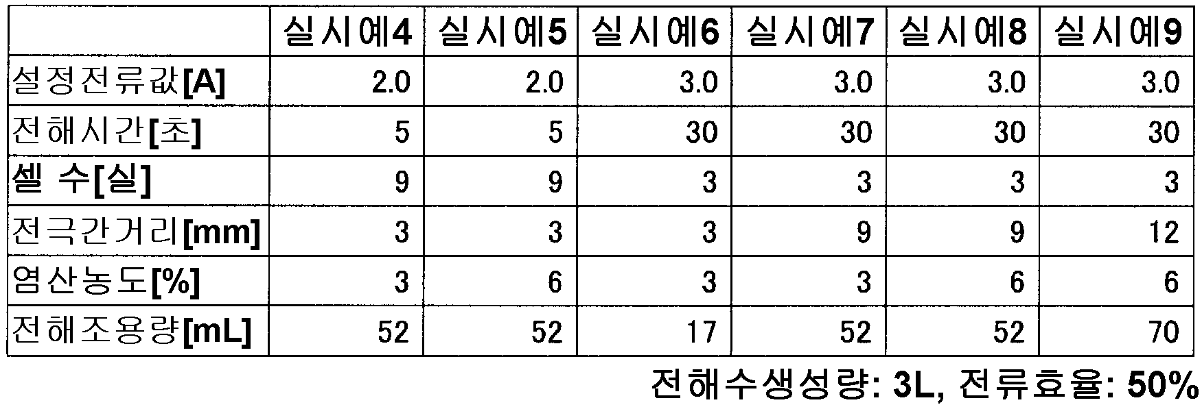
(전기 분해 방법)(Electrolysis method)
3리터의 탱크(4)에 수도수를 저장시키고, 전해수 제조 장치의 본체에 탱크(4)를 설치하고, 수중 펌프로 탱크(4) 내의 교반을 개시하였다. 소정의 전류값으로 소정의 단위 시간 동안 전기 분해하였다. 전기 분해 후, 수중 펌프를 사용하여 탱크(4) 내를 10초간 교반하여 종료하였다. 그 후, 탱크(4)의 전해수(차아염소산수)를 패트병 등의 다른 용기로 옮기고 비웠다. 상기한 수순을 반복하고, 정전류를 유지할 수 없게 된 시점에서 전해조(3)의 사용을 종료하였다.The tap water was stored in the 3-
[표 5][Table 5]

(결과)(result)
표 5에 나타낸 바와 같이, 각각의 실시예에 있어서, 사전에 희염산이 충전된 1개의 전해조(3)를 사용하는 것만으로, 복수 회의 전기 분해가 가능하고, 또한 일정 범위의 유효 염소 농도의 전해수를 생성할 수 있는 것을 확인할 수 있었다.As shown in Table 5, electrolytic water can be electrolyzed a plurality of times and electrolytic water of a certain effective concentration of chlorine can be supplied to the
또한, 전류값과 단위 시간의 조정에 의하여, 제조되는 전해수의 염소 농도를 조정할 수 있는 것을 알았다. 구체적으로 예를 들면, pH 4.0∼7.5(바람직하게는 pH 4.0∼7.5), 염소 농도 1∼60 ppm(바람직하게는 10∼30 ppm, 특히 바람직하게는 10∼20 ppm)의 차아염소산수가 탱크(4)에 생성할 수 있는 것을 알 수 있었다.It has also been found that the chlorine concentration of the produced electrolytic water can be adjusted by adjusting the current value and the unit time. Concretely, for example, a hypochlorous acid water tank (for example, water) having a pH of 4.0 to 7.5 (preferably pH 4.0 to 7.5) and a chlorine concentration of 1 to 60 ppm (preferably 10 to 30 ppm, particularly preferably 10 to 20 ppm) 4). ≪ / RTI >
[산업상 이용가능성][Industrial applicability]
본 발명은, 원료수를 전기 분해함으로써 전해수를 제조하는 전해수 제조 장치, 전해수의 제조 방법 및 전해조에 적용할 수 있다.The present invention can be applied to an electrolytic water production apparatus for producing electrolytic water by electrolyzing raw material water, a production method of electrolytic water, and an electrolytic cell.
1A, 1B, 1C, 1D, 1E, 1F: 전해수 제조 장치
2, 130, 144: 도출구
3: 전해조
4: 탱크(혼합부, 용기)
4J: 설치부
5: 배관(혼합부)
6, 6a, 6b, 6c, 6d, 6e, 6f, 6g, 6h: 장착부
7: 제어부
9: 천장벽(가이드부)
10: 바닥벽(가이드부)
11: 측벽(가이드부)
13, 124: 삽통부(가이드부)
15, 123: 단자 접속부
16A, 16B, 70, 82, 125, 139, 149: 걸림부
19, 131, 145, 106: 연결부
20: 관통공(구멍부)
30, 30i: 하우징
31: 전극판
33: 스페이서
45: 전극봉(단자)
120: 고정 괘지부
121: 가동 괘지부
131R: 관통공(구멍부)
137: 판 스프링
148: 관통공(구멍부)
182: 포트(혼합부)
207R: 유로(혼합부)
C: 전해실
G: 가이드부
M: 저장 스페이스(공간)1A, 1B, 1C, 1D, 1E, 1F: electrolytic water production apparatus
2, 130, 144:
3: electrolytic bath
4: tank (mixing part, container)
4J: Installation section
5: Piping (mixing part)
6, 6a, 6b, 6c, 6d, 6e, 6f, 6g, 6h:
7:
9: Thick barrier (guide part)
10: bottom wall (guide portion)
11: Side wall (guide portion)
13, 124: insertion portion (guide portion)
15, 123: Terminal connection part
16A, 16B, 70, 82, 125, 139, 149:
19, 131, 145, and 106:
20: Through hole (hole)
30, 30i: housing
31: Electrode plate
33: Spacer
45: Electrode (terminal)
120: Fixed hanging part
121:
131R: Through hole (hole part)
137: leaf spring
148: Through hole (hole)
182: Port (mixed portion)
207R: flow path (mixed portion)
C: electrolytic chamber
G: Guide section
M: Storage space (space)
Claims (25)
상기 전해조에서 얻어진 상기 전해 생성물을 희석수와 혼합하여 전해수로 만드는 혼합부; 및
상기 전해조와 상기 혼합부의 사이에 설치되고, 상기 도출구와 연결시키는 구멍부가 형성된 연결부를 가지고, 또한 상기 전해조를 착탈(着脫) 가능하게 장착시키는 장착부
를 포함하고,
상기 전해조 및 상기 장착부는, 상기 전해조 또는 상기 연결부를 서로 상대적으로 이동시킴으로써, 상기 도출구와 상기 구멍부가 연통되거나 또는 연통 해제되도록 구성되며,
상기 도출구에는, 상기 전해조로부터의 액 누출을 방지하기 위해 액체의 통과를 방지하고 기체만을 투과시키는 기체 투과성 겸 소수성(疏水性) 필터가 설치되고,
상기 전해조는, 상기 도출구 이외가 봉지됨으로써 상기 전해조 내에 소정량의 원료수가 사전에 충전되고 봉지(封止)된 상태에서 또한 원료수가 그 내부에 추가 불가능하게 된 상태에서 상기 장착부에 장착되도록 구성되어 있는, 전해수 제조 장치.An electrolytic cell (electrolytic bath) for electrolyzing raw water to generate an electrolytic product and discharging the electrolytic product from an outlet;
A mixing unit for mixing the electrolytic product obtained from the electrolytic bath with dilution water to make electrolytic water; And
And a connecting portion provided between the electrolytic bath and the mixing portion and having an opening formed therein for connecting to the outlet and being detachably attached to the electrolytic bath,
Lt; / RTI >
The electrolytic bath and the mounting portion are configured such that the outlet and the hole are communicated or released by relatively moving the electrolytic bath or the connecting portion with each other,
The outlet is provided with a gas-permeable and hydrophobic filter which prevents passage of liquid and permeates only gas to prevent liquid leakage from the electrolytic bath,
The electrolytic cell is configured to be mounted on the mounting portion in a state where a predetermined amount of raw material water is pre-filled and sealed in the electrolytic bath by sealing other than the lead-out port, The electrolytic water producing device.
상기 장착부에는, 상기 도출구와 상기 구멍부가 연통되는 연결 위치를 향해 상기 전해조를 유도하는 가이드부가 구비되고,
상기 도출구와 상기 구멍부가 연통되었을 때 상기 전해조를 상기 장착부에 고정시키는 걸림부가, 상기 전해조 및 상기 장착부 중 적어도 어느 한쪽에 설치되어 있는, 전해수 제조 장치.The method according to claim 1,
Wherein the mounting portion is provided with a guide portion for guiding the electrolytic bath toward a connection position where the outlet and the hole are communicated,
And a latching portion for fixing the electrolytic bath to the mounting portion when the lead-out port and the hole are communicated, is provided in at least one of the electrolytic bath and the mounting portion.
상기 전해조는, 그 하우징의 내부에 복수의 전극판을 구비하고, 상기 복수의 전극판의 한쪽 판면을 일방향을 향해 간격을 두고 배열되고, 상기 복수의 전극판에 있어서 양단(兩端)에 위치하는 한 쌍의 전극판에 상기 하우징의 외측을 향해 돌출하는 단자가 각각 설치된 복극식 전해조이며,
상기 가이드부는, 상기 단자를 삽통(揷通)시키고, 또한 상기 단자와 접촉하여 상기 전해조에 통전(通電)하는 단자 접속부를 구비한 삽통부인, 전해수 제조 장치.3. The method of claim 2,
Wherein the electrolytic bath has a plurality of electrode plates inside the housing, one plate surface of the plurality of electrode plates is arranged with a gap toward one direction, and the electrolytic bath is disposed at both ends of the plurality of electrode plates A double electrode type electrolytic cell comprising a pair of electrode plates each having a terminal protruding toward the outside of the housing,
Wherein the guide portion is an insertion portion having a terminal connecting portion for allowing the terminal to pass therethrough and being in contact with the terminal to energize the electrolytic bath.
상기 장착부는, 상기 전해조를 회동(回動) 가능하게 괘지(掛止)시키는 고정 괘지부를 가지고,
상기 전해조는, 상기 고정 괘지부에 괘지하고, 이 고정 괘지부를 지점(支点)으로 하여 상기 전해조를 회동시켜 상기 장착부에 장착시키는 가동 괘지부를 가지고 있는, 전해수 제조 장치.4. The method according to any one of claims 1 to 3,
The mounting portion has a fixed hook portion for hanging the electrolytic bath so as to be rotatable,
Wherein the electrolytic bath has a movable hook portion which is mounted on the fixed hook portion and which rotates the electrolytic bath with the fixed hoop portion as a fulcrum to be mounted on the mounting portion.
상기 장착부는, 상기 연결부가 고정된 판 스프링을 구비하고,
상기 연결부는, 상기 판 스프링을 상기 장착부에 장착된 상기 전해조에 접근 또는 이격시킴으로써, 상기 연결부의 구멍부와 상기 도출구를 연통시키거나 또는 연통 해제시키도록 구성되어 있는, 전해수 제조 장치.4. The method according to any one of claims 1 to 3,
Wherein the mounting portion includes a leaf spring to which the connecting portion is fixed,
Wherein the connecting portion is configured to bring the plate spring into or out of contact with the electrolytic cell mounted on the mounting portion so that the hole portion of the connecting portion is communicated with or disconnected from the outlet.
상기 전해조의 동작을 제어하는 제어부; 및
상기 전해조에서 얻어진 상기 전해 생성물을 희석수와 혼합하여 전해수로 만드는 혼합부
를 포함하고,
상기 도출구에는, 상기 전해조로부터의 액 누출을 방지하기 위해 액체의 통과를 방지하고 기체만을 투과시키는 기체 투과성 겸 소수성 필터가 설치되고,
상기 전해조는 내부에 소정량의 상기 원료수가 사전에 충전되고, 상기 도출구 이외가 봉지됨으로써, 상기 내부에 원료수가 추가 불가능하게 된 상태에서 상기 혼합부에 연결할 수 있도록 구성되며,
상기 제어부는, 상기 전해조에 사전에 충전된 상기 소정량의 원료수 중 일부를 전기 분해하기 위해 소정의 단위 시간 동안 일정 전류값의 전류를 상기 전해조에 공급하고, 또한 상기 소정량의 원료수를 복수 회로 나누어 전기 분해하도록 구성되어 있는, 전해수 제조 장치.An electrolytic bath for electrolyzing raw water to generate an electrolytic product and discharging the electrolytic product from an outlet;
A control unit for controlling the operation of the electrolytic bath; And
A mixing part for mixing the electrolytic product obtained in the electrolytic bath with dilution water to make electrolytic water;
Lt; / RTI >
The outlet is provided with a gas permeable and hydrophobic filter which prevents liquid from passing therethrough and permeates only the gas to prevent liquid leakage from the electrolytic bath,
Wherein the electrolytic cell is configured to be connected to the mixing unit in a state in which a predetermined amount of the raw material water is preliminarily filled in the electrolytic cell and the water other than the lead-out port is sealed,
The control unit supplies a current of a constant current value to the electrolytic cell for a predetermined unit time in order to electrolyze a part of the predetermined amount of raw water previously filled in the electrolytic bath and further supplies a predetermined number of And electrolytically dissociating the electrolytic water.
상기 도출구와 연통시키는 구멍부가 형성된 연결부를 가지고, 또한 상기 전해조가 착탈 가능하게 장착되는 장착부를 더 포함하고,
상기 전해조 및 상기 장착부는, 상기 전해조 또는 상기 연결부를 서로 상대적으로 이동시킴으로써, 상기 도출구와 상기 구멍부가 연통되거나 또는 연통 해제되도록 구성되어 있는, 전해수 제조 장치.The method according to claim 6,
Further comprising a connecting portion having a hole portion for communicating with the outlet, and a mounting portion to which the electrolytic bath is detachably mounted,
Wherein the electrolytic bath and the mounting portion are configured such that the electrolytic bath or the connecting portion is relatively moved with respect to each other so that the outlet is communicated with or disconnected from the hole.
상기 장착부에는, 상기 도출구와 상기 구멍부가 연통되는 연결 위치를 향해 상기 전해조를 유도하는 가이드부가 구비되고,
상기 도출구와 상기 구멍부가 연통되었을 때 상기 전해조를 상기 장착부에 고정시키는 걸림부가, 상기 전해조 및 상기 장착부 중 적어도 어느 한쪽에 설치되어 있는, 전해수 제조 장치.8. The method of claim 7,
Wherein the mounting portion is provided with a guide portion for guiding the electrolytic bath toward a connection position where the outlet and the hole are communicated,
And a latching portion for fixing the electrolytic bath to the mounting portion when the lead-out port and the hole are communicated, is provided in at least one of the electrolytic bath and the mounting portion.
상기 제어부는, 상기 일정 전류값 및 상기 단위 시간 중 적어도 어느 한쪽을 설정 가능하고,
상기 제어부는, 상기 일정 전류값 및 상기 단위 시간 중 적어도 어느 한쪽을 설정함으로써, 상기 소정량의 원료수에 대하여 전기 분해를 행하는 횟수를 설정 가능한, 전해수 제조 장치.9. The method according to any one of claims 6 to 8,
Wherein the control unit is capable of setting at least one of the constant current value and the unit time,
Wherein the control unit sets the number of times electrolysis is performed for the predetermined number of raw materials by setting at least one of the constant current value and the unit time.
상기 제어부는, 상기 전해조에 대한 전기적인 접속이 해제되었을 때 상기 일정 전류값 또는 상기 단위 시간을 변경 가능한, 전해수 제조 장치.9. The method according to any one of claims 6 to 8,
Wherein the control unit is capable of changing the constant current value or the unit time when the electrical connection to the electrolytic cell is released.
상기 혼합부는, 상기 희석수를 저장하는 용기가 되고,
상기 용기를 착탈 가능하게 설치하는 설치부가 설치되어 있는, 전해수 제조 장치.9. The method according to any one of claims 6 to 8,
Wherein the mixing portion serves as a container for storing the diluted water,
And an installation section for detachably mounting the container is provided.
상기 전해 생성물이 배출되는 도출구를 가지는 하우징;
상기 하우징의 내부에 설치된 복수의 전극판;
상기 복수의 전극판의 한쪽 판면을 일방향을 향해 상기 복수의 전극판을 간격을 두고 배열시키는 스페이서; 및
인접하는 전극판의 사이에 형성되고 상기 원료수의 전기 분해가 행해지는 전해실
을 포함하고,
상기 도출구에는, 상기 전해조로부터의 액 누출을 방지하기 위해 액체의 통과를 방지하고 기체만을 투과시키는 기체 투과성 겸 소수성 필터가 설치되고,
상기 하우징은, 소정량의 원료수가 충전된 상태에서 상기 도출구 이외를 봉지함으로써 액밀하게 봉지 가능하며,
상기 하우징은, 통전 가능 시에 있어서, 그 내부에 상기 원료수를 추가 불가능하게 한 상태에서 상기 전해 생성물을 상기 도출구로부터 배출하도록 구성되어 있는, 전해조.An electrolytic cell for electrolytically decomposing raw material water to generate an electrolytic product by energization,
A housing having an outlet through which the electrolytic product is discharged;
A plurality of electrode plates provided inside the housing;
A spacer arranged on one of the plurality of electrode plates so that the plurality of electrode plates are spaced apart from each other in one direction; And
An electrolytic chamber formed between adjacent electrode plates and electrolyzing the raw water
/ RTI >
The outlet is provided with a gas permeable and hydrophobic filter which prevents liquid from passing therethrough and permeates only the gas to prevent liquid leakage from the electrolytic bath,
The housing is capable of sealing liquid-tightly by sealing other than the lead-out port in a state where a predetermined amount of raw material is filled,
Wherein the housing is configured to discharge the electrolytic product from the outlet when the electrolytic current is available and the water of the raw material can not be added to the inside of the housing.
상기 전해실의 외측에 상기 원료수를 저장하는 공간이 형성되어 있는, 전해조.13. The method of claim 12,
And a space for storing the raw water is formed outside the electrolytic chamber.
상기 공간은, 상기 전해실의 측방 및 상방 중 적어도 어느 한쪽에 설치되어 있는, 전해조.14. The method of claim 13,
Wherein the space is provided on at least one of a side and an upper side of the electrolytic chamber.
상기 복수의 전극판과 상기 복수의 스페이서가 교호적(交互的)으로 배치되어 있는, 전해조.15. The method according to any one of claims 12 to 14,
Wherein the plurality of electrode plates and the plurality of spacers are arranged alternately.
원료수를 전기 분해하여 전해 생성물을 발생시키고 상기 전해 생성물을 배출시키는 도출구를 가지고, 상기 도출구에는 전해조로부터의 액 누출을 방지하기 위해 액체의 통과를 방지하고 기체만을 투과시키는 기체 투과성 겸 소수성 필터가 설치되는 동시에 상기 도출구 이외가 봉지됨에 따라 소정량의 원료수가 추가 불가능하도록 충전된 전해조에, 사전에 설정된 단위 시간 동안 일정 전류값의 전류를 상기 전해조에 공급하여 상기 소정량의 원료수 중 일부의 전기 분해를 행하는 전기 분해 공정과, 상기 전기 분해 공정에서 발생한 전해 생성물을 희석수와 혼합하여 전해수를 제조하는 혼합 공정을, 원료수를 상기 전해조에 추가하지 않고 복수 회 행함으로써 상기 전해수를 반복적으로 제조하는 제조 공정; 및
상기 전기 분해 공정이 복수 회 행해진 후의 전해조를, 소정량의 원료수가 충전된 다른 전해조와 교환하는 교환 공정
을 포함하는
전해수의 제조 방법.As a method for producing electrolytic water,
And an outlet for electrolyzing the raw water to generate an electrolytic product and discharging the electrolytic product, wherein the outlet is provided with a gas-permeable and hydrophobic filter for preventing passage of liquid to prevent liquid leakage from the electrolytic bath, And a current of a constant current value is supplied to the electrolytic cell charged to an electrolytic cell charged so that a predetermined amount of raw material can not be added due to sealing other than the lead-out port, for a predetermined unit time, An electrolytic step of electrolyzing the electrolytic solution produced in the electrolytic step and mixing the electrolytic products produced in the electrolytic step with dilution water to prepare electrolytic water by repeating the mixing step a plurality of times without adding the raw water to the electrolytic bath, Manufacturing processes to manufacture; And
An electrolytic process in which the electrolytic process is performed a plurality of times by the electrolysis process is replaced with another electrolytic cell filled with a predetermined amount of the raw material water
Containing
A method for producing electrolytic water.
상기 제조 공정 후에, 상기 전해조의 교환 시기를 통지하는 통지 공정을 추가로 포함하는 전해수의 제조 방법.17. The method of claim 16,
Further comprising a notification step of notifying the replacement time of the electrolytic bath after the manufacturing step.
상기 통지 공정에서는, 상기 전해조에 흐르는 전류의 전압값 또는 전류값에 기초하여, 상기 전해조의 교환 시기를 통지하는, 전해수의 제조 방법.18. The method of claim 17,
Wherein the notification step notifies the replacement time of the electrolytic bath based on a voltage value or a current value of a current flowing in the electrolytic bath.
상기 통지 공정에서는, 행해진 상기 전기 분해 공정의 횟수, 또는 상기 단위 시간의 누계 시간에 기초하여, 상기 전해조의 교환 시기를 통지하는, 전해수의 제조 방법.18. The method of claim 17,
Wherein the notifying step notifies the replacing time of the electrolytic bath based on the number of times of the electrolysis step or the cumulative time of the unit time performed.
상기 전기 분해 공정에서의 상기 일정 전류값 및 상기 단위 시간 중 적어도 한쪽을 설정하고, 또한 설정된 상기 일정 전류값과 상기 단위 시간에 따라, 상기 전해조의 교환 시기까지의, 전기 분해 공정의 횟수 또는 단위 시간의 누계 시간을 설정하는, 전해수의 제조 방법.20. The method of claim 19,
Wherein the electrolytic process includes a step of setting at least one of the constant current value and the unit time in the electrolysis step and setting the number of times of the electrolytic process or the unit time until the exchange time of the electrolytic bath in accordance with the set constant current value and the unit time Of the electrolytic water is set.
소정량 및 소정 농도의 원료수를, 상기 전해조에 충전하고 봉지하는 봉지 공정을 더 포함하고,
상기 전해조에 충전되어 있는 원료수의 양 및 농도 중 적어도 한쪽에 따라, 상기 전해조의 교환 시기까지의, 전기 분해 공정의 횟수 또는 단위 시간의 누계 시간을 설정하는, 전해수의 제조 방법.21. The method according to claim 19 or 20,
Further comprising an encapsulating step of filling and sealing the predetermined amount and the predetermined amount of raw water in the electrolytic cell,
Wherein the total number of times of the electrolysis process or the cumulative time of the unit time up to the replacement time of the electrolytic bath is set according to at least one of the amount and the concentration of the raw water filled in the electrolytic bath.
상기 전해조의 내부에 설치된 복수의 전극판의 장수에 따라, 상기 전기 분해 공정에서의 단위 시간을 변경하는, 전해수의 제조 방법.21. The method according to any one of claims 16 to 20,
Wherein a unit time in the electrolysis step is changed according to the number of electrode plates provided in the electrolytic cell.
상기 전해조를 교환한 후의 1회째의 전기 분해 공정에서의 단위 시간은, 2회째 이후의 전기 분해 공정에서의 단위 시간보다 길게 되도록 설정되는, 전해수의 제조 방법.21. The method according to any one of claims 16 to 20,
Wherein the unit time in the first electrolysis step after the electrolyzer is changed is set to be longer than the unit time in the second electrolysis step and the subsequent electrolysis step.
상기 전해조에 소정량의 원료수를 충전하고 봉지하는 봉지 공정을 더 포함하고,
상기 교환 공정에서는, 상기 봉지 공정에서 봉지된 전해조를, 전해수 제조 장치에 장착되어 있는 전해조와 교환하는, 전해수의 제조 방법.21. The method according to any one of claims 16 to 20,
Further comprising a sealing step of filling and sealing the electrolytic bath with a predetermined amount of raw water,
In the replacing step, the electrolytic cell sealed in the sealing step is exchanged with the electrolytic bath attached to the electrolytic water producing apparatus.
상기 원료수가, 농도 0.75∼21 질량%의 희염산인, 전해수의 제조 방법.21. The method according to any one of claims 16 to 20,
Wherein the raw material water is a dilute hydrochloric acid at a concentration of 0.75 to 21 mass%.
Applications Claiming Priority (5)
| Application Number | Priority Date | Filing Date | Title |
|---|---|---|---|
| JPJP-P-2012-218855 | 2012-09-28 | ||
| JPJP-P-2012-218856 | 2012-09-28 | ||
| JP2012218856A JP5836243B2 (en) | 2012-09-28 | 2012-09-28 | Electrolyzed water production equipment |
| JP2012218855A JP5871766B2 (en) | 2012-09-28 | 2012-09-28 | Electrolytic layer, electrolyzed water production apparatus, and electrolyzed water production method |
| PCT/JP2013/075865 WO2014050865A1 (en) | 2012-09-28 | 2013-09-25 | Electrolyzed water production device, electrolyzed water production method, and electrolytic bath |
Publications (2)
| Publication Number | Publication Date |
|---|---|
| KR20150038613A KR20150038613A (en) | 2015-04-08 |
| KR101781012B1 true KR101781012B1 (en) | 2017-09-25 |
Family
ID=50388262
Family Applications (1)
| Application Number | Title | Priority Date | Filing Date |
|---|---|---|---|
| KR1020157005850A Active KR101781012B1 (en) | 2012-09-28 | 2013-09-25 | Electrolyzed water production device, electrolyzed water production method, and electrolytic bath |
Country Status (7)
| Country | Link |
|---|---|
| US (2) | US20150259223A1 (en) |
| EP (1) | EP2902532A4 (en) |
| KR (1) | KR101781012B1 (en) |
| CN (1) | CN104662205B (en) |
| HK (1) | HK1210506A1 (en) |
| TW (1) | TWI485291B (en) |
| WO (1) | WO2014050865A1 (en) |
Families Citing this family (11)
| Publication number | Priority date | Publication date | Assignee | Title |
|---|---|---|---|---|
| JP6031489B2 (en) * | 2014-11-11 | 2016-11-24 | 森永乳業株式会社 | Embedded device and method for controlling embedded device |
| JP6578181B2 (en) * | 2015-10-08 | 2019-09-18 | モレックス エルエルシー | Electrolyzed water production equipment |
| JP6209255B1 (en) * | 2016-07-21 | 2017-10-04 | 株式会社日本トリム | Electrolyzed water generator |
| JP6853049B2 (en) * | 2017-01-18 | 2021-03-31 | 株式会社日本トリム | Electrolyzed water generator |
| JP6875133B2 (en) * | 2017-01-18 | 2021-05-19 | 株式会社日本トリム | Electrolyzed water generator |
| JP6870992B2 (en) * | 2017-01-18 | 2021-05-12 | 株式会社日本トリム | Electrolyzed water generator |
| CN108344772B (en) * | 2017-12-29 | 2023-07-11 | 宁波欧琳科技股份有限公司 | Method and system for detecting purified water tank electrolyte sheet |
| CN110195236A (en) * | 2018-02-24 | 2019-09-03 | 苏州倍爱尼生物技术有限公司 | A kind of coupling type electrolytic water generating device |
| CN112263196B (en) * | 2020-10-23 | 2022-02-25 | 珠海格力电器股份有限公司 | Electrolysis control method and device, electrolysis equipment and readable storage medium |
| JP6917553B1 (en) * | 2020-10-30 | 2021-08-11 | パナソニックIpマネジメント株式会社 | Space purification device and space purification system using it |
| CN115849514A (en) * | 2022-11-29 | 2023-03-28 | 合肥荣事达电子电器集团有限公司 | Subacid brineelectrolysis generates device |
Citations (5)
| Publication number | Priority date | Publication date | Assignee | Title |
|---|---|---|---|---|
| JP2000005757A (en) * | 1998-06-19 | 2000-01-11 | Morinaga Milk Ind Co Ltd | Economical method for producing electrolytic sterilized water |
| US20040211676A1 (en) * | 2001-07-16 | 2004-10-28 | Miox Corporation | Electrolytic cell for surface and point of use disinfection |
| JP2009262116A (en) * | 2008-04-23 | 2009-11-12 | Hokuetsu:Kk | Batch type electrolysis |
| JP2010058052A (en) * | 2008-09-03 | 2010-03-18 | Morinaga Milk Ind Co Ltd | Bipolar electrolytic cell and spacer used therefor |
| WO2011157812A1 (en) * | 2010-06-17 | 2011-12-22 | Industrie De Nora S.P.A. | System for electrochemical generation of hypochlorite |
Family Cites Families (24)
| Publication number | Priority date | Publication date | Assignee | Title |
|---|---|---|---|---|
| US4085028A (en) * | 1974-11-21 | 1978-04-18 | Electro-Chlor Corporation | Electrolytic chlorination device |
| JPS5847982Y2 (en) | 1979-07-24 | 1983-11-01 | 松下電器産業株式会社 | alkaline water maker |
| JPS56152787A (en) * | 1980-04-30 | 1981-11-26 | Miyakawa Seisakusho:Kk | Water ionizer |
| JPS56152783A (en) * | 1980-04-30 | 1981-11-26 | Miyakawa Seisakusho:Kk | Water ionizer |
| JPS56152786A (en) * | 1980-04-30 | 1981-11-26 | Miyakawa Seisakusho:Kk | Water ionizer |
| JPH027673Y2 (en) | 1985-11-26 | 1990-02-23 | ||
| JPH01169856A (en) | 1987-12-25 | 1989-07-05 | Hitachi Ltd | Getter device for cathode-ray tube |
| US5133848A (en) * | 1991-08-05 | 1992-07-28 | Oxi Generators, Inc. | On-site oxidant generator |
| JP3228435B2 (en) * | 1992-05-28 | 2001-11-12 | 船井電機株式会社 | Ion water generator |
| US5836479A (en) * | 1994-07-25 | 1998-11-17 | Sprayex L.L.C. | Rechargeable containers and dispensers |
| US5925240A (en) * | 1997-05-20 | 1999-07-20 | United States Filter Corporation | Water treatment system having dosing control |
| US6736966B2 (en) * | 1999-05-25 | 2004-05-18 | Miox Corporation | Portable water disinfection system |
| CN1315738C (en) * | 2000-12-12 | 2007-05-16 | 沃特皮克公司 | Device and method for generating and applying ozonated water |
| GB2393737B (en) * | 2002-10-03 | 2005-08-17 | Sterilox Tech Int Ltd | Electronic treatment of an aqueous salt solution |
| JP2006205144A (en) * | 2005-01-25 | 2006-08-10 | Hokuetsu:Kk | Batch-type electrolytic hypochlorous acid-containing sterilization water generator |
| JP2006239674A (en) * | 2005-03-02 | 2006-09-14 | Hokuetsu:Kk | Electrolyzed water generator |
| JP2006346650A (en) * | 2005-06-20 | 2006-12-28 | Sawada Kinji | Apparatus and method for producing alkali sterilization water |
| JP4950547B2 (en) * | 2006-04-13 | 2012-06-13 | ヒロセ電機株式会社 | Slightly acidic water generator |
| JP4668884B2 (en) * | 2006-11-06 | 2011-04-13 | ヒロセ電機株式会社 | Slightly acidic water generator |
| FR2955842B1 (en) * | 2010-02-04 | 2012-03-16 | Thea Lab | FLUID FOR PACKAGING A LIQUID WITH A DROP-IN DISTRIBUTION HEAD |
| JP5156792B2 (en) * | 2010-05-31 | 2013-03-06 | 森永乳業株式会社 | Electrolyzed water production equipment |
| JP5156793B2 (en) * | 2010-05-31 | 2013-03-06 | 森永乳業株式会社 | Electrolyzed water production equipment |
| CN103080019B (en) * | 2010-06-14 | 2014-07-23 | 株式会社微酸性电解水研究所 | Electrolysis device and method for producing slightly acidic electrolyzed water |
| JP5772102B2 (en) * | 2011-03-17 | 2015-09-02 | セントラル硝子株式会社 | Electrode for fluorine compound electrosynthesis |
-
2013
- 2013-09-25 CN CN201380050499.0A patent/CN104662205B/en active Active
- 2013-09-25 WO PCT/JP2013/075865 patent/WO2014050865A1/en not_active Ceased
- 2013-09-25 EP EP13842250.6A patent/EP2902532A4/en not_active Withdrawn
- 2013-09-25 KR KR1020157005850A patent/KR101781012B1/en active Active
- 2013-09-25 TW TW102134551A patent/TWI485291B/en active
- 2013-09-25 US US14/431,551 patent/US20150259223A1/en not_active Abandoned
- 2013-09-25 HK HK15111156.0A patent/HK1210506A1/en unknown
-
2018
- 2018-04-03 US US15/943,933 patent/US20180222775A1/en not_active Abandoned
Patent Citations (5)
| Publication number | Priority date | Publication date | Assignee | Title |
|---|---|---|---|---|
| JP2000005757A (en) * | 1998-06-19 | 2000-01-11 | Morinaga Milk Ind Co Ltd | Economical method for producing electrolytic sterilized water |
| US20040211676A1 (en) * | 2001-07-16 | 2004-10-28 | Miox Corporation | Electrolytic cell for surface and point of use disinfection |
| JP2009262116A (en) * | 2008-04-23 | 2009-11-12 | Hokuetsu:Kk | Batch type electrolysis |
| JP2010058052A (en) * | 2008-09-03 | 2010-03-18 | Morinaga Milk Ind Co Ltd | Bipolar electrolytic cell and spacer used therefor |
| WO2011157812A1 (en) * | 2010-06-17 | 2011-12-22 | Industrie De Nora S.P.A. | System for electrochemical generation of hypochlorite |
Also Published As
| Publication number | Publication date |
|---|---|
| US20180222775A1 (en) | 2018-08-09 |
| EP2902532A1 (en) | 2015-08-05 |
| HK1210506A1 (en) | 2016-04-22 |
| US20150259223A1 (en) | 2015-09-17 |
| CN104662205B (en) | 2017-10-24 |
| TWI485291B (en) | 2015-05-21 |
| TW201418522A (en) | 2014-05-16 |
| EP2902532A4 (en) | 2016-05-25 |
| CN104662205A (en) | 2015-05-27 |
| WO2014050865A1 (en) | 2014-04-03 |
| KR20150038613A (en) | 2015-04-08 |
Similar Documents
| Publication | Publication Date | Title |
|---|---|---|
| KR101781012B1 (en) | Electrolyzed water production device, electrolyzed water production method, and electrolytic bath | |
| EP2100623B1 (en) | Spray dispenser | |
| MX2010014391A (en) | Electrolysis de-scaling method with constant output. | |
| JP6609489B2 (en) | Electrolyte analyzer | |
| WO2008035868A1 (en) | Apparatus for producing antiseptic solution including chlorine | |
| KR20020005433A (en) | Electrolytic liquid and apparatus for producing same | |
| JP2013169505A (en) | Device and method for producing sterile water | |
| TWI437129B (en) | Electrolyzed water production apparatus | |
| JP5836243B2 (en) | Electrolyzed water production equipment | |
| JP5871766B2 (en) | Electrolytic layer, electrolyzed water production apparatus, and electrolyzed water production method | |
| JP6143968B2 (en) | Electrolyzed water generator and electrode unit | |
| CN210582268U (en) | Cleaning assembly and fruit and vegetable cleaning machine | |
| KR100756030B1 (en) | Portable Electrolytic Disinfection Water Generator | |
| TWM555856U (en) | Hydrogen generator, and hydrogen gas inhaler including the same | |
| CN218899371U (en) | Cleaning equipment with disinfection function | |
| JP2011218001A (en) | Hand washer | |
| KR100904682B1 (en) | Sodium hypochlorite generator | |
| JP6391659B2 (en) | Hydrogen water generator | |
| CN213963276U (en) | Water tank mounting structure and dish washing machine | |
| CN214387392U (en) | Dispenser installation structure, dishwasher | |
| CN112120641B (en) | Water tank installation structure, dishwasher | |
| CN112137553B (en) | Water tank sealing installation structure and dish washer | |
| CN112168107B (en) | Dispenser mounting structure and dish washer | |
| CN115919225B (en) | A cleaning device with disinfection function | |
| CN114468925B (en) | Dispensers and dishwashers |
Legal Events
| Date | Code | Title | Description |
|---|---|---|---|
| A201 | Request for examination | ||
| PA0105 | International application |
St.27 status event code: A-0-1-A10-A15-nap-PA0105 |
|
| PA0201 | Request for examination |
St.27 status event code: A-1-2-D10-D11-exm-PA0201 |
|
| PG1501 | Laying open of application |
St.27 status event code: A-1-1-Q10-Q12-nap-PG1501 |
|
| D13-X000 | Search requested |
St.27 status event code: A-1-2-D10-D13-srh-X000 |
|
| D14-X000 | Search report completed |
St.27 status event code: A-1-2-D10-D14-srh-X000 |
|
| E902 | Notification of reason for refusal | ||
| PE0902 | Notice of grounds for rejection |
St.27 status event code: A-1-2-D10-D21-exm-PE0902 |
|
| AMND | Amendment | ||
| P11-X000 | Amendment of application requested |
St.27 status event code: A-2-2-P10-P11-nap-X000 |
|
| P13-X000 | Application amended |
St.27 status event code: A-2-2-P10-P13-nap-X000 |
|
| E601 | Decision to refuse application | ||
| PE0601 | Decision on rejection of patent |
St.27 status event code: N-2-6-B10-B15-exm-PE0601 |
|
| T11-X000 | Administrative time limit extension requested |
St.27 status event code: U-3-3-T10-T11-oth-X000 |
|
| T13-X000 | Administrative time limit extension granted |
St.27 status event code: U-3-3-T10-T13-oth-X000 |
|
| AMND | Amendment | ||
| P11-X000 | Amendment of application requested |
St.27 status event code: A-2-2-P10-P11-nap-X000 |
|
| P13-X000 | Application amended |
St.27 status event code: A-2-2-P10-P13-nap-X000 |
|
| PX0901 | Re-examination |
St.27 status event code: A-2-3-E10-E12-rex-PX0901 |
|
| E902 | Notification of reason for refusal | ||
| PE0902 | Notice of grounds for rejection |
St.27 status event code: A-1-2-D10-D21-exm-PE0902 |
|
| AMND | Amendment | ||
| P11-X000 | Amendment of application requested |
St.27 status event code: A-2-2-P10-P11-nap-X000 |
|
| P13-X000 | Application amended |
St.27 status event code: A-2-2-P10-P13-nap-X000 |
|
| PX0701 | Decision of registration after re-examination |
St.27 status event code: A-3-4-F10-F13-rex-PX0701 |
|
| X701 | Decision to grant (after re-examination) | ||
| GRNT | Written decision to grant | ||
| PR0701 | Registration of establishment |
St.27 status event code: A-2-4-F10-F11-exm-PR0701 |
|
| PR1002 | Payment of registration fee |
St.27 status event code: A-2-2-U10-U12-oth-PR1002 Fee payment year number: 1 |
|
| PG1601 | Publication of registration |
St.27 status event code: A-4-4-Q10-Q13-nap-PG1601 |
|
| P22-X000 | Classification modified |
St.27 status event code: A-4-4-P10-P22-nap-X000 |
|
| PR1001 | Payment of annual fee |
St.27 status event code: A-4-4-U10-U11-oth-PR1001 Fee payment year number: 4 |
|
| PR1001 | Payment of annual fee |
St.27 status event code: A-4-4-U10-U11-oth-PR1001 Fee payment year number: 5 |
|
| PR1001 | Payment of annual fee |
St.27 status event code: A-4-4-U10-U11-oth-PR1001 Fee payment year number: 6 |
|
| PR1001 | Payment of annual fee |
St.27 status event code: A-4-4-U10-U11-oth-PR1001 Fee payment year number: 7 |
|
| PR1001 | Payment of annual fee |
St.27 status event code: A-4-4-U10-U11-oth-PR1001 Fee payment year number: 8 |
|
| R18-X000 | Changes to party contact information recorded |
St.27 status event code: A-5-5-R10-R18-oth-X000 |
|
| PR1001 | Payment of annual fee |
St.27 status event code: A-4-4-U10-U11-oth-PR1001 Fee payment year number: 9 |
|
| U11 | Full renewal or maintenance fee paid |
Free format text: ST27 STATUS EVENT CODE: A-4-4-U10-U11-OTH-PR1001 (AS PROVIDED BY THE NATIONAL OFFICE) Year of fee payment: 9 |