KR101765457B1 - Security system and method using wireless transmitter-receiver - Google Patents
Security system and method using wireless transmitter-receiver Download PDFInfo
- Publication number
- KR101765457B1 KR101765457B1 KR1020120039188A KR20120039188A KR101765457B1 KR 101765457 B1 KR101765457 B1 KR 101765457B1 KR 1020120039188 A KR1020120039188 A KR 1020120039188A KR 20120039188 A KR20120039188 A KR 20120039188A KR 101765457 B1 KR101765457 B1 KR 101765457B1
- Authority
- KR
- South Korea
- Prior art keywords
- wireless transceiver
- wireless
- portable terminal
- transceivers
- delete delete
- Prior art date
- Legal status (The legal status is an assumption and is not a legal conclusion. Google has not performed a legal analysis and makes no representation as to the accuracy of the status listed.)
- Active
Links
Images


Classifications
-
- H—ELECTRICITY
- H04—ELECTRIC COMMUNICATION TECHNIQUE
- H04W—WIRELESS COMMUNICATION NETWORKS
- H04W64/00—Locating users or terminals or network equipment for network management purposes, e.g. mobility management
-
- G—PHYSICS
- G01—MEASURING; TESTING
- G01S—RADIO DIRECTION-FINDING; RADIO NAVIGATION; DETERMINING DISTANCE OR VELOCITY BY USE OF RADIO WAVES; LOCATING OR PRESENCE-DETECTING BY USE OF THE REFLECTION OR RERADIATION OF RADIO WAVES; ANALOGOUS ARRANGEMENTS USING OTHER WAVES
- G01S5/00—Position-fixing by co-ordinating two or more direction or position line determinations; Position-fixing by co-ordinating two or more distance determinations
- G01S5/02—Position-fixing by co-ordinating two or more direction or position line determinations; Position-fixing by co-ordinating two or more distance determinations using radio waves
- G01S5/0252—Radio frequency fingerprinting
-
- G—PHYSICS
- G01—MEASURING; TESTING
- G01S—RADIO DIRECTION-FINDING; RADIO NAVIGATION; DETERMINING DISTANCE OR VELOCITY BY USE OF RADIO WAVES; LOCATING OR PRESENCE-DETECTING BY USE OF THE REFLECTION OR RERADIATION OF RADIO WAVES; ANALOGOUS ARRANGEMENTS USING OTHER WAVES
- G01S5/00—Position-fixing by co-ordinating two or more direction or position line determinations; Position-fixing by co-ordinating two or more distance determinations
- G01S5/02—Position-fixing by co-ordinating two or more direction or position line determinations; Position-fixing by co-ordinating two or more distance determinations using radio waves
- G01S5/10—Position of receiver fixed by co-ordinating a plurality of position lines defined by path-difference measurements, e.g. omega or decca systems
-
- H—ELECTRICITY
- H04—ELECTRIC COMMUNICATION TECHNIQUE
- H04W—WIRELESS COMMUNICATION NETWORKS
- H04W4/00—Services specially adapted for wireless communication networks; Facilities therefor
- H04W4/02—Services making use of location information
- H04W4/029—Location-based management or tracking services
-
- H—ELECTRICITY
- H04—ELECTRIC COMMUNICATION TECHNIQUE
- H04W—WIRELESS COMMUNICATION NETWORKS
- H04W4/00—Services specially adapted for wireless communication networks; Facilities therefor
- H04W4/90—Services for handling of emergency or hazardous situations, e.g. earthquake and tsunami warning systems [ETWS]
-
- G—PHYSICS
- G01—MEASURING; TESTING
- G01S—RADIO DIRECTION-FINDING; RADIO NAVIGATION; DETERMINING DISTANCE OR VELOCITY BY USE OF RADIO WAVES; LOCATING OR PRESENCE-DETECTING BY USE OF THE REFLECTION OR RERADIATION OF RADIO WAVES; ANALOGOUS ARRANGEMENTS USING OTHER WAVES
- G01S2205/00—Position-fixing by co-ordinating two or more direction or position line determinations; Position-fixing by co-ordinating two or more distance determinations
- G01S2205/001—Transmission of position information to remote stations
- G01S2205/006—Transmission of position information to remote stations for emergency situations
Landscapes
- Engineering & Computer Science (AREA)
- Computer Networks & Wireless Communication (AREA)
- Signal Processing (AREA)
- General Physics & Mathematics (AREA)
- Physics & Mathematics (AREA)
- Radar, Positioning & Navigation (AREA)
- Remote Sensing (AREA)
- Environmental & Geological Engineering (AREA)
- Public Health (AREA)
- Emergency Management (AREA)
- Health & Medical Sciences (AREA)
- Business, Economics & Management (AREA)
- Alarm Systems (AREA)
- Mobile Radio Communication Systems (AREA)
Abstract
건물과 같은 공간에서 발생한 화재 등의 위급 상황 시에도 건물의 전원 상태에 구애받지 않고 건물 내부의 사람들의 위치 추적 정보를 실시간으로 클라우드망을 통해 외부 공공기관과 공유할 수 있도록 하는 무선 송수신기를 이용한 보안 시스템 및 방법이 제공된다. 상기 무선 송수신기를 이용한 보안 시스템은 단위 공간 내에 존재하는 휴대용 단말기; 상기 단위 공간 내에서 상기 휴대용 단말기의 전파 강도를 감지하는 무선 송수신기; 및 상기 무선 송수신기로부터 제공받은 상기 휴대용 단말기의 전파 강도 및 상기 무선 송수신기의 위치정보를 통해 상기 휴대용 단말기의 위치를 파악하는 중앙 제어 서버를 포함한다. Security using a wireless transceiver that allows people in the building to share location tracking information in real-time with external public institutions in a cloud environment, regardless of the power state of the building, even in an emergency such as a fire in a space like a building A system and method are provided. The security system using the wireless transceiver includes a portable terminal existing in a unit space; A wireless transceiver for sensing a radio wave intensity of the portable terminal in the unit space; And a central control server for determining the position of the portable terminal through the field intensity of the portable terminal and the position information of the wireless transceiver provided from the wireless transceiver.
Description
본 발명은 무선 송수신기를 이용한 보안 시스템 및 방법에 관한 것으로서, 보다 구체적으로는 건물과 같은 공간에서 발생한 화재 등의 위급 상황 시에도 건물의 전원 상태에 구애받지 않고 건물 내부의 사람들의 위치 추적 정보를 실시간으로 클라우드망을 통해 외부 공공기관과 공유할 수 있도록 하는 무선 송수신기를 이용한 보안 시스템 및 방법에 대한 것이다. The present invention relates to a security system and method using a wireless transceiver, and more particularly, to a security system and method using a wireless transceiver, and more particularly, To a security system and method using a wireless transceiver that enables a user to share with an external public entity through a cloud network.
종래의 건물 보안 시스템에서는, 감시가 필요한 장소에 카메라를 설치하여 감시 가능을 수행하거나 출입 통제를 위해 RFID(Radio Frequency Identification) 카드 등을 발급하여 제한된 장소를 출입할 수 있는 권한을 부여했다. In a conventional building security system, a camera is installed in a place where monitoring is required to perform monitoring, or an RFID (Radio Frequency Identification) card is issued for access control to allow access to a restricted place.
또한, 카메라에 의해 촬영된 영상으로부터 일정 공간 내부에 사람이 존재하는지 여부를 분석하여 기본적인 감시 기능을 수행하고, 경우에 따라서 이 영상 정보를 이용하여 건물의 전력 제어, 냉난방 제어 등의 스마트 기능을 수행하기도 한다. In addition, a basic monitoring function is performed by analyzing whether a person exists in a certain space from the image photographed by the camera, and if necessary, smart functions such as power control of the building, cooling and heating control are performed using the image information It is also said.
이렇게 종래의 보안 시스템은 영상 감시 영역 내에 존재하는 사람들에 한정하여 감시가 이루어지기 때문에 만약 화재나 정전과 같은 위급 상황 발생시에는 대처하기 어렵다는 문제가 있다. The conventional security system has a problem that it is difficult to cope with an emergency situation such as a fire or a power outage because the security system is limited to the people in the video surveillance area.
보다 구체적으로, 감시 영역 내에 존재하는 사람들에 대한 촬영만 이루어지기 때문에, 감시 영역 밖에 존재하는 사람에 대해서는 이들의 이동 상황, 존재 여부에 대한 파악과 같은 일체의 실시간 감시 가능을 수행할 수 없게 된다. 또한, 건물 내부에 존재하는 소수의 사람들이나 침입자를 찾아내기가 곤란하고 건물 전체가 정전이 될 경우 감시 시스템이 무용지물이 될 수도 있다. More specifically, since only the people in the surveillance area are photographed, it is impossible to perform all the real-time surveillance such as identification of the presence or absence of those persons who are outside the surveillance area. Also, if it is difficult to find a small number of persons or intruders in the building and the entire building is blacked out, the surveillance system may become useless.
한편, 종래의 보안 시스템의 위치 추적 기술에는 삼각 측량 기술, 적외선을 이용한 인식 기술, 초음파를 이용한 위치 인식 기술 등이 존재하지만, 이러한 기술을 적용한 위치 추적 장치는 반드시 밀폐된 공간에서 어떠한 형태로든 안정된 전원을 지속적으로 공급할 수 있는 고정식 장치가 필수적으로 설치되어야 한다. Meanwhile, there is a triangulation technology, a recognition technology using infrared rays, a location recognition technology using ultrasonic waves, and the like. However, a location tracking device using such a technology is not necessarily a stable power source A fixed device capable of constantly supplying a continuous supply of the product is required.
그러나, 밀폐 공간에서 화재 등과 같은 긴급 재해 발생시에는 위치 추적을 위한 고정식 장치의 안정적 동작을 보장할 수가 없다. 이로 인하여, 화재 진압이나 인명 구조를 위해 투입되는 소방관뿐만 아니라 터널, 또는 지하에서 작업하는 근로자들의 위치를 추적하는 목적에 사용하기에는 적합하지 못하다는 문제점이 있다. However, in case of an emergency such as a fire in a closed space, stable operation of the stationary device for tracking the position can not be guaranteed. This has the problem that it is not suitable for use in the purpose of tracking the location of workers working in tunnels or underground as well as firefighters injected for fire suppression or life saving.
[선행기술문헌][Prior Art Literature]
한국공개공보 2004-0011672호Korean Laid-Open Publication No. 2004-0011672
본 발명이 해결하려는 과제는, 화재나 정전과 같이 보안 시스템이 동작하지 않는 긴급 상황 또는 긴급 재해 발생시에도 건물 내부의 사람들의 위치를 실시간으로 획득하는 것이 가능한 무선 송수신기를 이용한 보안 시스템 및 방법을 제공하는 것이다. A problem to be solved by the present invention is to provide a security system and method using a wireless transceiver capable of acquiring the location of people in a building in real time even in emergency or emergency disaster where security system does not operate such as fire or power failure will be.
본 발명이 해결하려는 과제들은 이상에서 언급한 과제들로 제한되지 않으며, 언급되지 않은 또 다른 과제들은 아래의 기재로부터 당업자에게 명확하게 이해될 수 있을 것이다.The problems to be solved by the present invention are not limited to the above-mentioned problems, and other matters not mentioned can be clearly understood by those skilled in the art from the following description.
상기 과제를 해결하기 위한 본 발명의 무선 송수신기를 이용한 보안 시스템의 일 태양은 단위 공간 내에 존재하는 휴대용 단말기; 상기 단위 공간 내에서 상기 휴대용 단말기의 전파 강도를 감지하는 무선 송수신기; 및 상기 무선 송수신기로부터 제공되는 상기 휴대용 단말기의 전파 강도 및 상기 무선 송수신기의 위치정보를 통해 상기 휴대용 단말기의 위치를 파악하는 중앙 제어 서버를 포함할 수 있다. According to an aspect of the present invention, there is provided a security system using a wireless transceiver, comprising: a portable terminal existing in a unit space; A wireless transceiver for sensing a radio wave intensity of the portable terminal in the unit space; And a central control server for locating the portable terminal through the field strength of the portable terminal and the location information of the wireless transceiver provided from the wireless transceiver.
상기 과제를 해결하기 위한 본 발명의 무선 송수신기를 이용한 보안 방법의 일 태양은 단위 공간 내에 존재하는 무선 송수신기가 상기 단위 공간 내에 존재하는 휴대용 단말기의 전파 강도를 감지하는 단계; 중앙 제어 서버가 상기 무선 송수신기로부터 상기 휴대용 단말기의 전파 강도 정보를 제공받는 단계; 상기 무선 송수신기의 위치정보와 상기 제공받은 상기 전파 강도 정보를 통해 상기 휴대용 단말기의 위치를 파악하는 단계를 포함 수 있다. According to another aspect of the present invention, there is provided a security method using a wireless transceiver, including: sensing a radio wave strength of a portable terminal existing in a unit space of a wireless transceiver existing in a unit space; Receiving a radio wave intensity information of the portable terminal from the radio transceiver; And determining the location of the portable terminal through the location information of the radio transceiver and the received radio wave intensity information.
더 나아가, 특정 조건 상황 발생 시 상기 단위 공간 내의 내부 전원을 차단하고 외부 전원 공급 모드로 전환하는 단계를 더 포함할 수 있다. Further, the method may further include switching off the internal power supply in the unit space and switching to the external power supply mode when a specific condition occurs.
본 발명의 기타 구체적인 사항들은 상세한 설명 및 도면들에 포함되어 있다.Other specific details of the invention are included in the detailed description and drawings.
본 발명의 실시예들에 따른 무선 송수신기를 이용한 보안 시스템 및 방법에 따르면, 건물의 화재나 정전과 같은 위급 상황 발생시에도 감시 영역에 대한 제한 없이 건물 내부의 모든 사람에 대한 위치를 추적할 수 있으며, 이에 따라 건물 내부 사람들의 위치 정보가 외부 기관에 실시간으로 공유될 수 있게 됨으로써 비상 상황에 대한 신속한 대처가 가능하다.According to the security system and method using the wireless transceiver according to the embodiments of the present invention, even when an emergency occurs such as a fire or a power failure of a building, As a result, the location information of the people inside the building can be shared with external organizations in real time, so that the emergency situation can be dealt with promptly.
도 1은 본 발명의 실시예들에 따른 무선 송수신기를 이용한 보안 시스템이 적용되는 건물 내부 모습의 측면 개략도이다.
도 2는 본 발명의 실시예들에 따른 무선 송수신기를 이용한 보안 시스템이 적용되는 건물 내부 모습의 평면 개략도이다.
도 3은 본 발명의 실시예들에 따른 무선 송수신기를 이용한 보안 시스템의 전체 구성도이다.
도 4은 다수의 무선 송수신기가 방형으로 위치하는 모습을 보여주는 그림이다.
도 5는 도 4과 같이 방형으로 위치한 다수의 무선 송수신기를 통해 휴대용 단말기의 위치를 파악하는 방법을 설명하기 위한 개략도이다.
도 6 내지 도 8은 다수의 무선 송수신기가 방형으로 위치하지 않을 경우에 휴대용 단말기의 위치를 파악하는 방법을 설명하기 위한 개략도이다.
도 9는 본 발명의 실시예들에 따른 무선 송수신기를 이용한 보안 방법의 순서도이다.FIG. 1 is a side schematic view of a building interior to which a security system using a wireless transceiver according to embodiments of the present invention is applied.
FIG. 2 is a schematic plan view of a building interior to which a security system using a wireless transceiver according to embodiments of the present invention is applied.
3 is an overall configuration diagram of a security system using a wireless transceiver according to embodiments of the present invention.
FIG. 4 is a diagram showing a plurality of wireless transceivers positioned in a square shape.
FIG. 5 is a schematic view illustrating a method of locating a portable terminal through a plurality of wireless transceivers positioned in a square as shown in FIG.
6 to 8 are schematic views for explaining a method of locating a portable terminal when a plurality of radio transceivers are not positioned in a square shape.
9 is a flowchart of a security method using a wireless transceiver according to embodiments of the present invention.
이하, 첨부된 도면을 참조하여 본 발명의 바람직한 실시예를 상세히 설명한다. 본 발명의 이점 및 특징, 그리고 그것들을 달성하는 방법은 첨부되는 도면과 함께 상세하게 후술되어 있는 실시 예들을 참조하면 명확해질 것이다. 그러나 본 발명은 이하에서 게시되는 실시 예들에 한정되는 것이 아니라 서로 다른 다양한 형태로 구현될 수 있으며, 단지 본 실시 예들은 본 발명의 게시가 완전하도록 하고, 본 발명이 속하는 기술분야에서 통상의 지식을 가진 자에게 발명의 범주를 완전하게 알려주기 위해 제공되는 것이며, 본 발명은 청구항의 범주에 의해 정의될 뿐이다. 명세서 전체에 걸쳐 동일 참조 부호는 동일 구성 요소를 지칭한다.Hereinafter, preferred embodiments of the present invention will be described in detail with reference to the accompanying drawings. BRIEF DESCRIPTION OF THE DRAWINGS The advantages and features of the present invention and the manner of achieving them will become apparent with reference to the embodiments described in detail below with reference to the accompanying drawings. The present invention may, however, be embodied in many different forms and should not be construed as limited to the embodiments set forth herein. Rather, these embodiments are provided so that this disclosure will be thorough and complete, and will fully convey the scope of the invention to those skilled in the art. Is provided to fully convey the scope of the invention to those skilled in the art, and the invention is only defined by the scope of the claims. Like reference numerals refer to like elements throughout the specification.
다른 정의가 없다면, 본 명세서에서 사용되는 모든 용어(기술 및 과학적 용어를 포함)는 본 발명이 속하는 기술분야에서 통상의 지식을 가진 자에게 공통적으로 이해될 수 있는 의미로 사용될 수 있을 것이다. 또 일반적으로 사용되는 사전에 정의되어 있는 용어들은 명백하게 특별히 정의되어 있지 않는 한 이상적으로 또는 과도하게 해석되지 않는다. Unless defined otherwise, all terms (including technical and scientific terms) used herein may be used in a sense commonly understood by one of ordinary skill in the art to which this invention belongs. Also, commonly used predefined terms are not ideally or excessively interpreted unless explicitly defined otherwise.
도 1은 본 발명의 실시예들에 따른 무선 송수신기를 이용한 보안 시스템이 적용되는 건물 내부 모습의 측면 개략도이고, 도 2는 본 발명의 실시예들에 따른 무선 송수신기를 이용한 보안 시스템이 적용되는 건물 내부 모습의 평면 개략도이며, 도 3은 본 발명의 실시예들에 따른 무선 송수신기를 이용한 보안 시스템의 전체 구성도이다.FIG. 1 is a side schematic view of a building interior to which a security system using a wireless transceiver according to embodiments of the present invention is applied. FIG. 2 is a perspective view of a building inside a building to which a security system using a wireless transceiver according to embodiments of the present invention is applied FIG. 3 is an overall configuration diagram of a security system using a wireless transceiver according to embodiments of the present invention. Referring to FIG.
우선, 도 1 내지 도 3을 참조하면, 본 발명의 실시예들에 따른 무선 송수신기를 이용한 보안 시스템은 휴대용 단말기(이하, 도 5 내지 도 8의 P), 무선 송수신기(200), 및 중앙 제어 서버(310 및/또는 320)를 포함할 수 있다. 1 to 3, a security system using a wireless transceiver according to embodiments of the present invention includes a portable terminal (hereinafter, referred to as P in FIGS. 5 to 8), a
우선 무선 송수신기(200)는 단위 공간 내에서 휴대용 단말기의 전파 강도를 감지한다. First, the
단위 공간은 하나 이상의 무선 송수신기(200)가 그 공간 내에 존재하고 있는 휴대용 단말기의 전파 수신 강도를 모두 수집할 수 있는 공간을 의미하는 것으로 한다. 예를 들어 도 2 전체와 같이 하나의 건물 내 한 층 전체가 하나의 단위 공간이 될 수도 있고, 한 층의 일부(도 2의 A 내지 E)일 수도 있을 것이다. The unit space means a space in which at least one
무선 송수신기는 휴대폰 전파 안테나(201), 무선랜 라우터(203), 블루투스 송수신기(205), NFC(Near Field Communication) 송수신기 중 적어도 어느 하나가 사용될 수 있으나, 상기 나열된 것 이외에 다른 종류의 송수신기도 무방하다. At least one of the mobile
휴대폰 전파 안테나(201) 또는 무선랜 라우터(203)는 건물의 한 층에 적어도 한 개 이상 설치되어 각각 장거리 및 중거리 정보를 송수신하는 것이 목적이다. 블루투스 송수신기(205)는 각 층에서 필요한 구역마다 설치되며 10미터 이내의 단거리 정보를 송수신하는 것이 목적이고, NFC 송수신기(207)는 각 층에서 필요한 구역 또는 구역간 이동 경계부에 설치되어 초단거리 정보를 송수신한다. The cellular
이러한 무선 송수신기들은 도 1 또는 도 2와 같이 단위 공간 내에 여러 종류들이 함께 설치되어 있어도 무방하고, 필요에 따라 한 가지 종류만 설치되어 있더라도 무방하다. As shown in FIG. 1 or FIG. 2, these wireless transceivers may be installed in the unit space together with a plurality of types, and only one type may be provided if necessary.
다만, 각 종류의 무선 송수신기의 전파 수신 가능 범위가 서로 다르기 때문에 어떠한 종류의 무선 송수신기를 사용하느냐에 따라 단위 공간의 크기 또한 달라진다. However, because the radio receivable ranges of the respective types of radio transceivers are different from each other, the size of the unit space varies depending on what kind of radio transceiver is used.
예를 들어 휴대폰 전파 안테나(201) 또는 무선랜 라우터(203)를 사용하는 경우에는 단위 공간이 건물 내 하나의 층 전체가 될 수 있다. 또한 만약 블루투스 송수신기(205)를 사용하는 경우라면 도 2에처럼 층 내부에서 구획된 공간(A 내지 E) 중 하나를 담당하거나 또는 구획된 두 개 이상의 공간에 존재하는 블루투스 송수신기(205)들이 상기 두 개 이상의 공간을 함께 커버할 수도 있을 것이다. For example, when the
휴대용 단말기는 단위 공간 내에 존재하는 사람(10)이 휴대할 수 있는 무선 송수신 단말기로서, 휴대용 단말기는 단위 공간 내에 존재하는 무선 송수신기(200)와 무선 통신이 가능하며, 이에 따라 휴대용 단말기가 송신하는 신호 전파의 강도를 무선 송수신기(200)가 감지한다. A portable terminal is a wireless transmitting / receiving terminal that can be carried by a
휴대용 단말기는 사람(10)이 항상 휴대하는 것을 전제로 하며, 이로써 화재와 같은 비상 상황 발생시 휴대용 단말기에 대한 위치 추적을 통해 휴대용 단말기를 휴대한 사람(10)에 대한 위치 추적이 가능해진다. The portable terminal is assumed to be always carried by the
휴대용 단말기는 무선 송수신기(200)의 종류에 따라 무선 송수신기(200)가 수신할 수 있는 전파를 송신하는 기능을 갖춘 것이면 어떠한 종류라도 무관하다. 예를 들어, 개개인이 거의 모두 휴대하고 있는 통신 기기인 휴대폰일 수 있는데, 이 경우 무선 송수신기(200)는 휴대폰 전파 안테나(201)가 될 수 있을 것이다. 또한 블루투스 통신 기능 또는 NFC 통신 기능이 가능한 휴대폰일 경우라면 무선 송수신기(200)로서 블루투스 송수신기(205) 또는 NFC 송수신기(207)가 별개로 또는 함께 사용될 수 있을 것이다. The portable terminal may be of any type as long as it has a function of transmitting radio waves that the
또는 휴대폰 이외에 무선 송수신기(200)와 무선 통신 기능을 갖춘 별도로 제작된 단말이어도 무관하다. 이하에서는 설명의 편의를 위해 휴대폰을 휴대용 단말기로, 휴대폰 전파 안테나(201), 블루투스 송수신기(205), NFC 송수신기(207) 등을 무선 송수신기(200)로 가정하여 설명할 것이나, 이미 설명한 바와 같이 본 발명에서 휴대용 단말기 및 무선 송수신기는 이에 한정하지 않는다. Or may be a separately manufactured terminal having a wireless communication function with the
본 발명의 실시예들에 따른 무선 송수신기를 이용한 보안 시스템에 따르면 휴대폰을 지닌 사람이 건물 내로 진입하면 건물 내부의 무선 송수신기를 통해 건물 진입 상태임을 알리는 신호를 휴대폰으로 송신한다. 그러면 휴대폰은 미리 정해진 어플리케이션을 자동 실행하거나 건물 진입 상태임을 알 수 있는 모드로 자동 전환된다. 이 모드에서는 건물 내부의 다양한 전파 송수신 장비들과 정보 교환이 가능하지며, 이에 따라 휴대폰을 지닌 사람에 대한 실시간 위치가 파악된다. According to the security system using the wireless transceiver according to the embodiments of the present invention, when a person with a cellular phone enters a building, a signal indicating that the building is in the building is transmitted to the cellular phone through a wireless transceiver inside the building. Then, the mobile phone automatically switches to a mode in which the predetermined application is automatically executed or the building enters the building. In this mode, information can be exchanged with various radio transmission / reception devices inside the building, thereby realizing the position of the person having the mobile phone in real time.
예를 들어 건물에 출근하는 출근자의 경우 출근과 동시에 자동으로 휴대폰이 출근 모드로 전환되고, 각 출입문이나 각 구역 출입구를 통과할 경우 휴대폰의 NFC 기능을 이용하여 출입 여부를 확인할 수 있다. For example, in case of a worker arriving at a building, the mobile phone automatically switches to the work mode at the same time as the worker arrives. If the worker passes through each doorway or each area entrance,
방문자의 경우, 사전에 방문 시스템에 등록된 방문자 정보와 휴대폰 내부의 신상 정보를 자동으로 검색 및 비교하여 신분을 확인한 후 건물 방문 모드로 자동 전환할 수 있다. In the case of a visitor, the visitor information registered in the visiting system and the personal information inside the mobile phone can be automatically searched and compared in advance, and after confirming the identity, the user can automatically switch to the building visiting mode.
도 4는 다수의 무선 송수신기가 방형으로 위치하는 모습을 보여주는 그림이고, 도 5는 도 4과 같이 방형으로 위치한 다수의 무선 송수신기를 통해 휴대용 단말기의 위치를 파악하는 방법을 설명하기 위한 개략도이다.FIG. 4 is a diagram illustrating a plurality of wireless transceivers positioned in a square shape, and FIG. 5 is a schematic diagram illustrating a method of locating a portable terminal through a plurality of wireless transceivers positioned in a square as shown in FIG.
본 발명의 실시예들에 따른 무선 송수신기를 이용한 보안 시스템에 따르면 무선 송수신기가 다수개 존재할 수 있는데, 특히 적어도 세 개 이상 존재할 수 있다. 이는 하나의 층 또는 한 층 내부의 일부 구획된 공간을 2차원 평면이라고 할 때, 휴대폰을 지닌 각 개개인들의 위치를 정확히 파악해 내기 위함이다 According to the security system using the wireless transceiver according to the embodiments of the present invention, there may be a plurality of wireless transceivers, and at least three wireless transceivers may exist. This is to accurately identify the location of each individual cell phone when one or several compartmentalized spaces inside one floor are referred to as a two-dimensional plane
도 2에서 볼 수 있는 바와 같이 특정 종류의 무선 송수신기가 마치 방형의 꼭지점 위치에 배치되는 경우를 고려할 수 있다. 즉, 도 2에서 도시된 바와 같이 휴대폰 전파 안테나(201) 또는 무선랜 라우터(203)는 건물의 한 층의 네 모서리 부분에 위치할 수 있다. 또한, 블루투스 송수신기(205)는 구획된 각 공간(A 내지 D)의 각 모서리에 위치할 수 있다. As shown in FIG. 2, it can be considered that a specific type of radio transceiver is disposed at a vertex position of a square shape. That is, as shown in FIG. 2, the
어떤 종류의 무선 송수신기이든 이렇게 방형의 네 꼭지점의 위치에 적어도 세 개의 무선 송수신기가 위치하고 있는 경우를 도 4와 같이 표현한다. 도 4에서 S1 내지 S4는 복수의 무선 송수신기 각각을 의미하고 원형은 각 무선 송수신기가 커버하는 무선 통신 영역을 나타낸다. A case in which at least three radio transceivers are located at the positions of four square vertices of any type of radio transceiver is shown in FIG. In FIG. 4, S1 to S4 represent each of a plurality of radio transceivers, and a circle represents a radio communication area covered by each radio transceiver.
본 발명의 일 실시예에 따른 무선 송수신기를 이용한 보안 시스템에서는 적어도 세 개의 무선 송수신기를 통해 감지된 휴대폰의 전파 강도를 이용하여 휴대폰의 위치를 파악한다. In the security system using the wireless transceiver according to an embodiment of the present invention, the position of the mobile phone is determined by using the field intensity of the mobile phone detected through at least three wireless transceivers.
예를 들어, 도 5의 P(x, y)에 휴대폰을 지닌 사람이 위치하고 있다고 할 경우, 적어도 세 개의 무선 송수신기(S1 내지 S3)는 휴대폰이 송신하는 전파 강도를 감지한다. For example, if a person with a mobile phone is located at P (x, y) in FIG. 5, at least three radio transceivers S1 to S3 sense the strength of the radio waves transmitted by the mobile phone.
감지된 휴대폰의 전파 강도에 대한 정보는 중앙 제어 서버(310 또는 320)에 전달되며, 중앙 제어 서버는 상기 감지된 휴대폰의 전파 강도에 대한 정보와 이미 저장되어 있는 다수의 무선 송수신기의 위치 정보를 토대로 휴대폰의 위치(도 5의 P(x, y))를 파악한다. Information on the detected radio wave strength of the mobile phone is transmitted to the
먼저 S1과 S2에 대해 휴대폰의 X 축상의 위치를 Px(a) 라고 하고 S1에서 수신한 휴대폰의 전파 신호 강도를 i1, S2에서 수신한 휴대폰의 전파 신호 강도를 i2라고 하면, 휴대폰의 X 축상이 위치는 S1과 S2를 상기 신호 강도의 역수의 비율인 ( 1/(i1): 1/(i2) ), 다시 말해 (i2: i1)의 비율로 내분하는 점이라 할 수 있다. 따라서, X 축상의 휴대폰의 위치 Px(a)는 다음과 같이 계산된다. First, the position on the X axis of the mobile phone is referred to as Px (a) for S1 and S2, and the intensity of the radio wave signal of the mobile phone received at S1 is denoted by i1 and the received signal strength of the mobile phone received at S2 is denoted by i2. The position can be said to divide S1 and S2 into a ratio of the reciprocal of the signal intensity (1 / (i1): 1 / (i2)), that is, a ratio of (i2: i1). Therefore, the position Px (a) of the mobile phone on the X axis is calculated as follows.
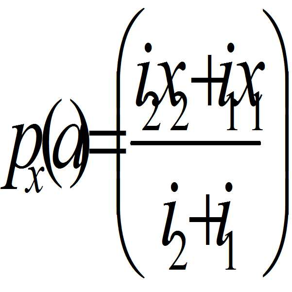
다음으로, S1과 S3에 대해 휴대폰의 Y 축상의 위치를 Py(d) 라고 하고 S1에서 수신한 휴대폰의 전파 신호 강도를 j1, S3에서 수신한 휴대폰의 전파 신호 강도를 j3라고 하면, 휴대폰의 Y 축상이 위치는 S1과 S3를 상기 신호 강도의 역수의 비율인 ( 1/(j1): 1/(j3) ), 다시 말해 (j3: j1)의 비율로 내분하는 점이라 할 수 있다. 따라서, Y 축상의 휴대폰의 위치 Py(d)는 다음과 같이 계산된다.Next, let Py (d) be the position on the Y-axis of the mobile phone with respect to S1 and S3, j1 be the strength of the cell signal received from S1, and j3 be the cell signal strength of the cell received from S3. The position on the axis can be regarded as a point dividing S1 and S3 into a ratio of (1 / (j1): 1 / (j3)), that is, a ratio of the reciprocal of the signal intensity to the ratio (j3: j1). Therefore, the position Py (d) of the mobile phone on the Y axis is calculated as follows.

결국, 휴대폰(사람)의 위치 P(x, y)는 다음과 같다. After all, the position P (x, y) of the mobile phone (person) is as follows.

이와 같은 방법을 통해 단위 공간 내의 휴대폰을 지닌 사람의 위치를 파악한다. 또한, 이렇게 무선 송수신기가 방형의 형태로 배치되어 있는 경우가 아니라고 하더라도 휴대폰(사람)의 위치를 구할 수 있다. Through such a method, the position of a person having a cell phone in the unit space is grasped. Further, even if the wireless transceiver is not arranged in a square shape, the position of the cellular phone (person) can be obtained.
도 6 내지 도 8은 다수의 무선 송수신기가 방형으로 위치하지 않을 경우에 휴대용 단말기의 위치를 파악하는 방법을 설명하기 위한 개략도이다.6 to 8 are schematic views for explaining a method of locating a portable terminal when a plurality of radio transceivers are not positioned in a square shape.
도 6 내지 도 8과 같이 세 개의 무선 송수신기가 방형이 아닌 형태로 배치되어 있는 경우에 중앙 제어 서버가 휴대폰의 위치를 파악하는 방법은 다음과 같을 수 있다. As shown in FIGS. 6 to 8, when the three radio transceivers are arranged in a non-square form, a method for the central control server to grasp the position of the mobile phone may be as follows.
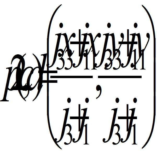
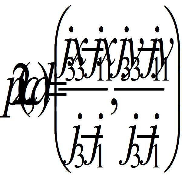
도 6에서와 같이 휴대폰이 위치하고 있는 경우의 휴대폰의 위치 좌표를 P(x, y)라고 하고, S1과 S2의 좌표를 각각 S1(x1, y1)과 S2(x2, y2)라 하며, S1에서 수신한 휴대폰의 전파 신호 강도를 i1, S2에서 수신한 휴대폰의 전파 신호 강도를 i2라고 하면, S1과 S2를 연결하는 직선상에서 상기 신호 강도의 역수의 비율인 ( 1/(i1): 1/(i2) ), 다시 말해 (i2: i1)의 비율로 내분하는 점은 P1(a, b)이다. 여기에서 P1(a, b)는 다음과 같이 계산된다. The coordinates of S1 and S2 are S1 (x1, y1) and S2 (x2, y2), respectively, and the coordinates of S1 and S2 are S1 (1 / (i1): 1 / ((1 / (i1)), which is the ratio of the reciprocal of the signal intensity on a straight line connecting S1 and S2, i2), i. e., i2: i1, is P1 (a, b). Here, P1 (a, b) is calculated as follows.

또한, S1과 S3에 대해 휴대폰의 위치 좌표를 P(x, y)라고 하고, S1에서 수신한 휴대폰의 전파 신호 강도를 j1, S3에서 수신한 휴대폰의 전파 신호 강도를 j3라고 하면, S1과 S3을 연결하는 직선 상에서 상기 신호 강도의 역수의 비율인 ( 1/(j1): 1/(j3) ), 다시 말해 (j3: j1)의 비율로 내분하는 점은 P2(c, d)이다. 여기에서 P2(c, d)는 다음과 같이 계산된다. Supposing that the position coordinate of the mobile phone with respect to S1 and S3 is P (x, y), the intensity of the radio wave signal of the mobile phone received at S1 is j1 and the intensity of the radio wave signal of the mobile phone received at S3 is j3, (C, d), which is the ratio of the reciprocal of the signal intensity on the straight line connecting the signal strengths (1 / (j1): 1 / (j3)), i.e. j3: j1. Here, P2 (c, d) is calculated as follows.

이후, S1과 S2를 연결하는 직선과 수직이면서 P1(a, b)을 지나는 직선(1)과 S1과 S3를 연결하는 직선과 수직이면서 P2(c, d)을 지나는 직선(2)의 교점을 구하고, 이를 휴대폰을 지닌 사람의 위치로 파악한다. Thereafter, the intersection of a straight line (1) passing through P1 (a, b) and a straight line connecting S1 and S3 and a straight line (2) passing through P2 (c, d) perpendicular to the straight line connecting S1 and S2 And finds it as the position of a person with a mobile phone.
도 7에서와 같이 휴대폰이 위치하고 있는 경우에도, 위와 유사한 과정을 통해 구할 수 있다. 도 6과 동일한 내용에 대한 설명은 생략하고 다른 점만 설명하면, S1과 S2를 연결하는 직선의 연장선상에 위치한 P1(a, b)는 도 6과는 달리 다음과 같이 계산된다. Even in the case where the mobile phone is located as shown in FIG. 7, it can be obtained through a process similar to the above. 6, P1 (a, b) located on an extension line of a straight line connecting S1 and S2 is calculated as follows, unlike FIG.

또한, S1과 S3을 연결하는 직선 상에서 P2(c, d)는 다음과 같다. On the straight line connecting S1 and S3, P2 (c, d) is as follows.
이후, S1과 S2를 연결하는 직선의 연장선과 수직이면서 P1(a, b)을 지나는 직선(3)과 S1과 S3를 연결하는 직선과 수직이면서 P2(c, d)을 지나는 직선(4)의 교점을 구하고, 이를 휴대폰을 지닌 사람의 위치로 파악한다.Then, a straight line 3 passing through P1 (a, b) and a
도 8에서와 같이 휴대폰이 위치하고 있는 경우에도, 위와 유사한 과정을 통해 구할 수 있다. 우선, S1과 S2를 연결하는 직선의 연장선상에 위치한 P1(a, b)는 도 6과는 달리 다음과 같이 계산된다. Even in the case where the mobile phone is located as shown in FIG. 8, it can be obtained through a process similar to the above. First, P1 (a, b) located on the extension line of the straight line connecting S1 and S2 is calculated as follows, unlike FIG.

또한, S1과 S3을 연결하는 직선의 연장선상에 위치한 P2(c, d)는 다음과 같다. In addition, P2 (c, d) located on the extension line of the straight line connecting S1 and S3 is as follows.
이후, S1과 S2를 연결하는 직선의 연장선과 수직이면서 P1(a, b)을 지나는 직선(5)과 S1과 S3를 연결하는 직선의 연장선과 수직이면서 P2(c, d)을 지나는 직선(6)의 교점을 구하고, 이를 휴대폰을 지닌 사람의 위치로 파악한다.Thereafter, a
위와 같은 방법을 통해 단위 공간 내부의 모든 사람(휴대폰)에 대한 위치 정보를 알아낼 수 있다. In this way, location information of all persons (mobile phones) inside the unit space can be obtained.
다시, 도 3으로 돌아와서, 위와 같이 구한 휴대폰의 위치 정보는 외부 관공서(소방서, 경찰서 등)로 통신망이나 클라우드를 이용하여 전송하고 실시간으로 갱신한다. 3, the location information of the mobile phone obtained as described above is transmitted to an external government office (a fire department, a police station, etc.) using a communication network or a cloud and updated in real time.
중앙 제어 서버(310 또는 320)는 건물의 내부에 위치하거나 또는 외부에 위치할 수 있고 또는 모두 위치할 수도 있다. 건물의 외부에만 위치한 경우라면(서버 2), 중앙 제어 서버 2(320)를 통해 수집된 정보를 관공서에서 직접 받아볼 수 있게 될 것이나, 건물의 내부에도 위치할 경우(서버1, 310)에는 위에서 설명했듯이 외부 서버(서버 2)와 서로 정보를 공유하는 것이 바람직하다. The
만약 화재나 전력 공급 중단 등과 같은 비상 상황이 발생한 경우 중앙 제어 서버(310, 320)는 단위 공간 내에 존재하는 모든 휴대용 단말기로 비상 메시지를 문자메시지, 경고음, 음성 등을 통해 전송하여 위급 상황이 발생했음을 알린다. 또한 현재의 상황이 정전인지 화재인지와 적절한 대피로에 대한 정보도 휴대용 단말기로 전송한다. If there is an emergency such as a fire or an interruption of power supply, the
만약, 건물 내부의 정전이나 화재로 인해 모든 장비가 사용 불가능 상태라면 외부 전원 공급 모드로 전환한다. 이로써, 평상시에 내부 전원(410)에 의해 공급되는 전력을 외부 전원(420)에 의해 공급하게 함으로써 무선 송수신기(200)의 지속적인 동작을 보장받는다. 또한, 휴대용 단말기의 경우 휴대폰과 같이 자체 베터리로 구동하기 때문에, 비상 상황시에 베터리가 모두 방전되지 않는 한 중앙 제어 서버가 각 휴대용 단말기의 위치를 지속적으로 파악할 수 있다. If all equipment is unavailable due to power failure or fire inside the building, switch to external power supply mode. Thus, the power supplied by the
결국, 비상 상황시 출동한 소방관이나 경찰관 등이 중앙 제어 서버를 통해 제공받은 사람(휴대용 단말기)의 위치를 실시간으로 수신하고, 휴대용 단말기를 통해 대피 정보등을 실시간으로 전송함으로써 비상 상황에 대한 신속한 대처가 가능하다.As a result, a firefighter or a police officer who is dispatched in an emergency situation receives the location of the person (portable terminal) provided through the central control server in real time, and transmits evacuation information in real time through the portable terminal, Is possible.
도 9는 본 발명의 실시예들에 따른 무선 송수신기를 이용한 보안 방법의 순서도이다.9 is a flowchart of a security method using a wireless transceiver according to embodiments of the present invention.
도 9를 참고하면, 본 발명의 실시예들에 따른 무선 송수신기를 이용한 보안 방법은 단위 공간 내에 존재하는 무선 수신기가 상기 단위 공간 내에 존재하는 휴대용 단말기의 전파 강도를 감지하는 단계(S910), 중앙 제어 서버가 상기 무선 수신기로부터 상기 휴대용 단말기의 전파 강도 정보를 제공받는 단계(S920), 상기 무선 수신기위 위치정보와 상기 제공받은 상기 전파 강도 정보를 통해 상기 휴대용 단말기의 위치를 파악하는 단계(S930)를 포함할 수 있고, 더 나아가, 특정 조건 상황 발생 시 상기 단위 공간 내의 내부 전원을 차단하고 외부 전원 공급 모드로 전환하는 단계(S940)를 더 포함할 수 있다. 9, a security method using a wireless transceiver according to embodiments of the present invention includes a step S910 of detecting a radio wave intensity of a portable terminal existing in a unit space of a wireless receiver existing in a unit space, The server receives the radio wave strength information of the portable terminal from the radio receiver in operation S920, and determines the location of the portable terminal through the radio receiver location information and the received radio wave intensity information in operation S930. And may further include a step S940 of turning off the internal power supply in the unit space and switching to the external power supply mode when a specific condition condition occurs.
S910 내지 S930 단계에 대해서는 도 4 내지 도 8 및 해당되는 설명 부분과 동일하므로 이를 통해 이해할 수 있으며, S940은 도 3을 통해 설명된 무선 송수신기를 이용한 보안 시스템의 내용과 거의 동일하므로 여기에서는 설명을 생략하도록 한다. Since steps S910 to S930 are the same as those of FIGS. 4 to 8 and corresponding description, it can be understood from this. S940 is substantially the same as the content of the security system using the wireless transceiver described with reference to FIG. 3, .
이상 첨부된 도면을 참조하여 본 발명의 실시예를 설명하였지만, 본 발명이 속하는 기술분야에서 통상의 지식을 가진 자는 본 발명이 그 기술적 사상이나 필수적인 특징을 변경하지 않고서 다른 구체적인 형태로 실시될 수 있다는 것을 이해할 수 있을 것이다. 그러므로 이상에서 기술한 실시예들은 모든 면에서 예시적인 것이며 한정적이 아닌 것으로 이해해야만 한다. While the present invention has been described in connection with what is presently considered to be practical exemplary embodiments, it is to be understood that the invention is not limited to the disclosed embodiments, but, on the contrary, You will understand. It is therefore to be understood that the above-described embodiments are illustrative in all aspects and not restrictive.
P: 휴대용 단말기
200: 무선 송수신기
310, 320: 중앙 제어 서버 P: Portable terminal
200: wireless transceiver
310, 320: Central control server
Claims (14)
상기 단위 공간 내에서 상기 제1 휴대용 단말기의 전파 강도를 감지하는 무선 송수신기; 및
상기 무선 송수신기로부터 제공되는 상기 제1 휴대용 단말기의 전파 강도 및 상기 무선 송수신기의 위치정보를 통해 상기 제1 휴대용 단말기의 위치를 파악하는 중앙 제어 서버를 포함하고
상기 무선 송수신기는 제1 내지 제3 무선 송수신기를 포함하고,
상기 중앙 제어 서버는,
상기 제1 및 제2 무선 송수신기의 각 위치 좌표값에 대하여, 상기 제1 및 제2 무선 송수신기가 각각 수신한 상기 제1 휴대용 단말기의 전파 강도의 역수의 비율로 내분한 점을 지나면서 상기 제1 무선 송수신기의 위치와 상기 제2 무선 송수신기의 위치를 연결한 선에 수직인 제1 직선과,
상기 제2 및 제3 무선 송수신기의 각 위치 좌표값에 대하여, 상기 제2 및 제3 무선 송수신기가 각각 수신한 상기 제1 휴대용 단말기의 전파 강도의 역수의 비율로 내분한 점을 지나면서 상기 제2 무선 송수신기의 위치와 상기 제3 무선 송수신기의 위치를 연결한 선에 수직인 제2 직선의 교점을 상기 제1 휴대용 단말기의 위치로 파악하는 무선 송수신기를 이용한 보안 시스템.A first portable terminal existing in a unit space;
A wireless transceiver for sensing a field strength of the first portable terminal within the unit space; And
And a central control server for determining the position of the first portable terminal through the field intensity of the first portable terminal and the position information of the wireless transceiver provided from the wireless transceiver
Wherein the wireless transceiver includes first through third wireless transceivers,
The central control server,
Wherein the first and second wireless transceivers transmit the position coordinates of the first and second wireless transceivers to the first and second wireless transceivers via the first and second wireless transceivers, A first straight line perpendicular to the line connecting the location of the wireless transceiver and the location of the second wireless transceiver,
Wherein the first and second wireless transceivers are connected to the second wireless transceiver and the second wireless transceiver, respectively, for each position coordinate value of the second and third wireless transceivers, And recognizes an intersection of a second straight line perpendicular to a line connecting the position of the wireless transceiver and the position of the third wireless transceiver as the position of the first portable terminal.
상기 단위 공간 내에 존재하는 제2 휴대용 단말기 더 포함하고,
상기 제1 내지 제3 무선 송수신기는 상기 제2 휴대용 단말기의 전파 강도를 감지하고,
상기 중앙 제어 서버는,
상기 제1 및 제2 무선 송수신기의 각 위치 좌표값에 대하여, 상기 제1 및 제2 무선 송수신기가 각각 수신한 상기 제2 휴대용 단말기의 전파 강도의 역수의 비율로 외분한 점을 지나면서 상기 제1 무선 송수신기의 위치와 상기 제2 무선 송수신기의 위치를 연결한 선에 수직인 제3 직선과,
상기 제2 및 제3 무선 송수신기의 각 위치 좌표값에 대하여, 상기 제2 및 제3 무선 송수신기가 각각 수신한 상기 제2 휴대용 단말기의 전파 강도의 역수의 비율로 외분한 점을 지나면서 상기 제2 무선 송수신기의 위치와 상기 제3 무선 송수신기의 위치를 연결한 선에 수직인 제4 직선의 교점을 상기 제2 휴대용 단말기의 위치로 파악하는 무선 송수신기를 이용한 보안 시스템.The method according to claim 1,
And a second portable terminal existing in the unit space,
The first to third radio transceivers sense the radio wave intensity of the second portable terminal,
The central control server,
Wherein the first and second wireless transceivers transmit the position coordinates of the first and second wireless transceivers to the first and second wireless transceivers via the first and second wireless transceivers, A third straight line perpendicular to the line connecting the position of the wireless transceiver and the position of the second wireless transceiver,
Wherein the second and third wireless transceivers transmit the position coordinates of the second and third wireless transceivers to the first wireless transceiver and the second wireless transceiver, And recognizes the intersection of a fourth straight line perpendicular to the line connecting the position of the wireless transceiver and the position of the third wireless transceiver as the position of the second portable terminal.
상기 중앙 제어 서버는 특정 조건 상황 발생 시 상기 단위 공간 내의 내부 전원을 차단하고 외부 전원 공급 모드로 전환하며,
상기 제1 및 제2 무선 송수신기는 특정 조건 상황 발생 시 상기 외부 전원 공급 모드에 의해 외부 전원을 공급받고,
상기 제1 휴대용 단말기는 특정 조건 상황 발생 여부와 무관하게 자체 베터리로 구동되는 무선 송수신기를 이용한 보안 시스템.The method according to claim 1,
Wherein the central control server interrupts the internal power supply in the unit space and switches to an external power supply mode when a specific condition occurs,
Wherein the first and second radio transceivers are supplied with external power by the external power supply mode when a specific condition occurs,
Wherein the first portable terminal is driven by its own battery irrespective of whether a specific condition condition occurs or not.
Priority Applications (1)
| Application Number | Priority Date | Filing Date | Title |
|---|---|---|---|
| KR1020120039188A KR101765457B1 (en) | 2012-04-16 | 2012-04-16 | Security system and method using wireless transmitter-receiver |
Applications Claiming Priority (1)
| Application Number | Priority Date | Filing Date | Title |
|---|---|---|---|
| KR1020120039188A KR101765457B1 (en) | 2012-04-16 | 2012-04-16 | Security system and method using wireless transmitter-receiver |
Publications (2)
| Publication Number | Publication Date |
|---|---|
| KR20130116627A KR20130116627A (en) | 2013-10-24 |
| KR101765457B1 true KR101765457B1 (en) | 2017-08-07 |
Family
ID=49635655
Family Applications (1)
| Application Number | Title | Priority Date | Filing Date |
|---|---|---|---|
| KR1020120039188A Active KR101765457B1 (en) | 2012-04-16 | 2012-04-16 | Security system and method using wireless transmitter-receiver |
Country Status (1)
| Country | Link |
|---|---|
| KR (1) | KR101765457B1 (en) |
Families Citing this family (1)
| Publication number | Priority date | Publication date | Assignee | Title |
|---|---|---|---|---|
| KR101489484B1 (en) * | 2014-04-15 | 2015-02-12 | 주식회사 디오엔지니어링 | Fire disaster prevention system using mobile cloud server |
-
2012
- 2012-04-16 KR KR1020120039188A patent/KR101765457B1/en active Active
Also Published As
| Publication number | Publication date |
|---|---|
| KR20130116627A (en) | 2013-10-24 |
Similar Documents
| Publication | Publication Date | Title |
|---|---|---|
| US10200879B2 (en) | Tactical rescue wireless base station | |
| Zhang et al. | A construction accident prevention system based on the Internet of Things (IoT) | |
| US10685103B2 (en) | Challenge and response system for identifying non-credentialed occupants and method | |
| WO2016063454A1 (en) | Information processing device and information processing method | |
| US9405948B2 (en) | Method for monitoring the functioning of an RFID-based radio communication network in a spatially extensive area | |
| JP2021002875A (en) | Radio communication equipment, radio communication terminal, radio communication system, radio communication method and recording medium | |
| Giuliano et al. | Indoor localization system for first responders in emergency scenario | |
| US12327455B2 (en) | Methods and devices for physical access control systems | |
| KR101057707B1 (en) | Logistics management system and logistics management method using iTAG | |
| KR101850610B1 (en) | Integrated Control System for Safety, Security and Tracking with RTLS | |
| Chen et al. | VIPS: A video-based indoor positioning system with centimeter-grade accuracy for the IoT | |
| KR20070110574A (en) | Traffic information service system using near field communication and its method | |
| US10735933B2 (en) | Communication management and communicating between a mobile communication device and another device | |
| KR101765457B1 (en) | Security system and method using wireless transmitter-receiver | |
| CN204349971U (en) | The supervisory control system of Minitype digital marker and fast lookup moving target | |
| US20210374366A1 (en) | Location system and method for tracking infected individuals | |
| Cil et al. | A comparative analysis of indoor positioning technologies in shipyard digitalization context | |
| KR20110042596A (en) | Mia tracking system and location tracking method | |
| KR102908918B1 (en) | A system providing location information of field personnel in an accident ship using UWB and RFID based on Public Safety LTE communication network and controlling method for the same | |
| CN108512750A (en) | Luggage control device based on Internet of Things and method | |
| KR102022503B1 (en) | Method for tracking position of things using local area wireless communication | |
| EP2833684B1 (en) | Sensors network for indoor tracking of mobile units | |
| CN109541536A (en) | A kind of location tracking system | |
| US10547980B1 (en) | Device movement correlations | |
| KR101092779B1 (en) | System and method for pursuit of a lost child |
Legal Events
| Date | Code | Title | Description |
|---|---|---|---|
| PA0109 | Patent application |
Patent event code: PA01091R01D Comment text: Patent Application Patent event date: 20120416 |
|
| PG1501 | Laying open of application | ||
| A201 | Request for examination | ||
| PA0201 | Request for examination |
Patent event code: PA02012R01D Patent event date: 20151104 Comment text: Request for Examination of Application Patent event code: PA02011R01I Patent event date: 20120416 Comment text: Patent Application |
|
| E902 | Notification of reason for refusal | ||
| PE0902 | Notice of grounds for rejection |
Comment text: Notification of reason for refusal Patent event date: 20170127 Patent event code: PE09021S01D |
|
| E701 | Decision to grant or registration of patent right | ||
| PE0701 | Decision of registration |
Patent event code: PE07011S01D Comment text: Decision to Grant Registration Patent event date: 20170721 |
|
| GRNT | Written decision to grant | ||
| PR0701 | Registration of establishment |
Comment text: Registration of Establishment Patent event date: 20170801 Patent event code: PR07011E01D |
|
| PR1002 | Payment of registration fee |
Payment date: 20170802 End annual number: 3 Start annual number: 1 |
|
| PG1601 | Publication of registration | ||
| PR1001 | Payment of annual fee |
Payment date: 20200728 Start annual number: 4 End annual number: 4 |
|
| PR1001 | Payment of annual fee |
Payment date: 20210727 Start annual number: 5 End annual number: 5 |
|
| PR1001 | Payment of annual fee |
Payment date: 20230801 Start annual number: 7 End annual number: 7 |
|
| PR1001 | Payment of annual fee |
Payment date: 20240724 Start annual number: 8 End annual number: 8 |