KR101748517B1 - Apparatus and method for selecting one of a first encoding algorithm and a second encoding algorithm using harmonics reduction - Google Patents
Apparatus and method for selecting one of a first encoding algorithm and a second encoding algorithm using harmonics reduction Download PDFInfo
- Publication number
- KR101748517B1 KR101748517B1 KR1020157032911A KR20157032911A KR101748517B1 KR 101748517 B1 KR101748517 B1 KR 101748517B1 KR 1020157032911 A KR1020157032911 A KR 1020157032911A KR 20157032911 A KR20157032911 A KR 20157032911A KR 101748517 B1 KR101748517 B1 KR 101748517B1
- Authority
- KR
- South Korea
- Prior art keywords
- audio signal
- encoding algorithm
- encoding
- algorithm
- quality measure
- Prior art date
- Legal status (The legal status is an assumption and is not a legal conclusion. Google has not performed a legal analysis and makes no representation as to the accuracy of the status listed.)
- Active
Links
Images


Classifications
-
- G—PHYSICS
- G10—MUSICAL INSTRUMENTS; ACOUSTICS
- G10L—SPEECH ANALYSIS TECHNIQUES OR SPEECH SYNTHESIS; SPEECH RECOGNITION; SPEECH OR VOICE PROCESSING TECHNIQUES; SPEECH OR AUDIO CODING OR DECODING
- G10L19/00—Speech or audio signals analysis-synthesis techniques for redundancy reduction, e.g. in vocoders; Coding or decoding of speech or audio signals, using source filter models or psychoacoustic analysis
- G10L19/04—Speech or audio signals analysis-synthesis techniques for redundancy reduction, e.g. in vocoders; Coding or decoding of speech or audio signals, using source filter models or psychoacoustic analysis using predictive techniques
- G10L19/16—Vocoder architecture
- G10L19/18—Vocoders using multiple modes
- G10L19/22—Mode decision, i.e. based on audio signal content versus external parameters
-
- G—PHYSICS
- G10—MUSICAL INSTRUMENTS; ACOUSTICS
- G10L—SPEECH ANALYSIS TECHNIQUES OR SPEECH SYNTHESIS; SPEECH RECOGNITION; SPEECH OR VOICE PROCESSING TECHNIQUES; SPEECH OR AUDIO CODING OR DECODING
- G10L19/00—Speech or audio signals analysis-synthesis techniques for redundancy reduction, e.g. in vocoders; Coding or decoding of speech or audio signals, using source filter models or psychoacoustic analysis
- G10L19/008—Multichannel audio signal coding or decoding using interchannel correlation to reduce redundancy, e.g. joint-stereo, intensity-coding or matrixing
-
- G—PHYSICS
- G10—MUSICAL INSTRUMENTS; ACOUSTICS
- G10L—SPEECH ANALYSIS TECHNIQUES OR SPEECH SYNTHESIS; SPEECH RECOGNITION; SPEECH OR VOICE PROCESSING TECHNIQUES; SPEECH OR AUDIO CODING OR DECODING
- G10L19/00—Speech or audio signals analysis-synthesis techniques for redundancy reduction, e.g. in vocoders; Coding or decoding of speech or audio signals, using source filter models or psychoacoustic analysis
- G10L19/02—Speech or audio signals analysis-synthesis techniques for redundancy reduction, e.g. in vocoders; Coding or decoding of speech or audio signals, using source filter models or psychoacoustic analysis using spectral analysis, e.g. transform vocoders or subband vocoders
- G10L19/032—Quantisation or dequantisation of spectral components
- G10L19/035—Scalar quantisation
-
- G—PHYSICS
- G10—MUSICAL INSTRUMENTS; ACOUSTICS
- G10L—SPEECH ANALYSIS TECHNIQUES OR SPEECH SYNTHESIS; SPEECH RECOGNITION; SPEECH OR VOICE PROCESSING TECHNIQUES; SPEECH OR AUDIO CODING OR DECODING
- G10L19/00—Speech or audio signals analysis-synthesis techniques for redundancy reduction, e.g. in vocoders; Coding or decoding of speech or audio signals, using source filter models or psychoacoustic analysis
- G10L19/04—Speech or audio signals analysis-synthesis techniques for redundancy reduction, e.g. in vocoders; Coding or decoding of speech or audio signals, using source filter models or psychoacoustic analysis using predictive techniques
- G10L19/08—Determination or coding of the excitation function; Determination or coding of the long-term prediction parameters
- G10L19/09—Long term prediction, i.e. removing periodical redundancies, e.g. by using adaptive codebook or pitch predictor
-
- G—PHYSICS
- G10—MUSICAL INSTRUMENTS; ACOUSTICS
- G10L—SPEECH ANALYSIS TECHNIQUES OR SPEECH SYNTHESIS; SPEECH RECOGNITION; SPEECH OR VOICE PROCESSING TECHNIQUES; SPEECH OR AUDIO CODING OR DECODING
- G10L19/00—Speech or audio signals analysis-synthesis techniques for redundancy reduction, e.g. in vocoders; Coding or decoding of speech or audio signals, using source filter models or psychoacoustic analysis
- G10L19/04—Speech or audio signals analysis-synthesis techniques for redundancy reduction, e.g. in vocoders; Coding or decoding of speech or audio signals, using source filter models or psychoacoustic analysis using predictive techniques
- G10L19/08—Determination or coding of the excitation function; Determination or coding of the long-term prediction parameters
- G10L19/12—Determination or coding of the excitation function; Determination or coding of the long-term prediction parameters the excitation function being a code excitation, e.g. in code excited linear prediction [CELP] vocoders
-
- G—PHYSICS
- G10—MUSICAL INSTRUMENTS; ACOUSTICS
- G10L—SPEECH ANALYSIS TECHNIQUES OR SPEECH SYNTHESIS; SPEECH RECOGNITION; SPEECH OR VOICE PROCESSING TECHNIQUES; SPEECH OR AUDIO CODING OR DECODING
- G10L19/00—Speech or audio signals analysis-synthesis techniques for redundancy reduction, e.g. in vocoders; Coding or decoding of speech or audio signals, using source filter models or psychoacoustic analysis
- G10L19/04—Speech or audio signals analysis-synthesis techniques for redundancy reduction, e.g. in vocoders; Coding or decoding of speech or audio signals, using source filter models or psychoacoustic analysis using predictive techniques
- G10L19/26—Pre-filtering or post-filtering
- G10L19/265—Pre-filtering, e.g. high frequency emphasis prior to encoding
-
- G—PHYSICS
- G10—MUSICAL INSTRUMENTS; ACOUSTICS
- G10L—SPEECH ANALYSIS TECHNIQUES OR SPEECH SYNTHESIS; SPEECH RECOGNITION; SPEECH OR VOICE PROCESSING TECHNIQUES; SPEECH OR AUDIO CODING OR DECODING
- G10L25/00—Speech or voice analysis techniques not restricted to a single one of groups G10L15/00 - G10L21/00
- G10L25/90—Pitch determination of speech signals
-
- G—PHYSICS
- G10—MUSICAL INSTRUMENTS; ACOUSTICS
- G10L—SPEECH ANALYSIS TECHNIQUES OR SPEECH SYNTHESIS; SPEECH RECOGNITION; SPEECH OR VOICE PROCESSING TECHNIQUES; SPEECH OR AUDIO CODING OR DECODING
- G10L19/00—Speech or audio signals analysis-synthesis techniques for redundancy reduction, e.g. in vocoders; Coding or decoding of speech or audio signals, using source filter models or psychoacoustic analysis
- G10L19/02—Speech or audio signals analysis-synthesis techniques for redundancy reduction, e.g. in vocoders; Coding or decoding of speech or audio signals, using source filter models or psychoacoustic analysis using spectral analysis, e.g. transform vocoders or subband vocoders
- G10L19/0212—Speech or audio signals analysis-synthesis techniques for redundancy reduction, e.g. in vocoders; Coding or decoding of speech or audio signals, using source filter models or psychoacoustic analysis using spectral analysis, e.g. transform vocoders or subband vocoders using orthogonal transformation
-
- G—PHYSICS
- G10—MUSICAL INSTRUMENTS; ACOUSTICS
- G10L—SPEECH ANALYSIS TECHNIQUES OR SPEECH SYNTHESIS; SPEECH RECOGNITION; SPEECH OR VOICE PROCESSING TECHNIQUES; SPEECH OR AUDIO CODING OR DECODING
- G10L19/00—Speech or audio signals analysis-synthesis techniques for redundancy reduction, e.g. in vocoders; Coding or decoding of speech or audio signals, using source filter models or psychoacoustic analysis
- G10L19/04—Speech or audio signals analysis-synthesis techniques for redundancy reduction, e.g. in vocoders; Coding or decoding of speech or audio signals, using source filter models or psychoacoustic analysis using predictive techniques
- G10L19/08—Determination or coding of the excitation function; Determination or coding of the long-term prediction parameters
-
- G—PHYSICS
- G10—MUSICAL INSTRUMENTS; ACOUSTICS
- G10L—SPEECH ANALYSIS TECHNIQUES OR SPEECH SYNTHESIS; SPEECH RECOGNITION; SPEECH OR VOICE PROCESSING TECHNIQUES; SPEECH OR AUDIO CODING OR DECODING
- G10L19/00—Speech or audio signals analysis-synthesis techniques for redundancy reduction, e.g. in vocoders; Coding or decoding of speech or audio signals, using source filter models or psychoacoustic analysis
- G10L2019/0001—Codebooks
- G10L2019/0002—Codebook adaptations
-
- G—PHYSICS
- G10—MUSICAL INSTRUMENTS; ACOUSTICS
- G10L—SPEECH ANALYSIS TECHNIQUES OR SPEECH SYNTHESIS; SPEECH RECOGNITION; SPEECH OR VOICE PROCESSING TECHNIQUES; SPEECH OR AUDIO CODING OR DECODING
- G10L19/00—Speech or audio signals analysis-synthesis techniques for redundancy reduction, e.g. in vocoders; Coding or decoding of speech or audio signals, using source filter models or psychoacoustic analysis
- G10L2019/0001—Codebooks
- G10L2019/0011—Long term prediction filters, i.e. pitch estimation
Landscapes
- Engineering & Computer Science (AREA)
- Physics & Mathematics (AREA)
- Computational Linguistics (AREA)
- Signal Processing (AREA)
- Health & Medical Sciences (AREA)
- Audiology, Speech & Language Pathology (AREA)
- Human Computer Interaction (AREA)
- Acoustics & Sound (AREA)
- Multimedia (AREA)
- Spectroscopy & Molecular Physics (AREA)
- Compression, Expansion, Code Conversion, And Decoders (AREA)
- Mathematical Physics (AREA)
Abstract
오디오 신호의 부분의 인코딩된 버전을 획득하도록 오디오 신호의 부분을 인코딩하기 위해 제 1 특성을 갖는 제 1 인코딩 알고리즘 및 제 2 특성을 갖는 제 2 인코딩 알고리즘 중 하나를 선택하기 위한 장치는 오디오 신호를 수신하고, 오디오 신호의 고조파의 진폭을 감소시키며, 오디오 신호의 필터링된 버전을 출력하도록 구성된 필터를 포함한다. 제 1 추정기는 제 1 인코딩 알고리즘을 사용하여 오디오 신호의 부분을 실제로 인코딩 및 디코딩하지 않고 제 1 인코딩 알고리즘과 관련되는 오디오 신호의 부분에 대한 제 1 품질 측정치로서 오디오 신호의 부분의 SNR(신호 대 잡음비) 또는 세그먼트 SNR을 추정할 시에 오디오 신호의 필터링된 버전을 사용하기 위해 제공된다. 제 2 추정기는 제 2 인코딩 알고리즘을 사용하여 오디오 신호의 부분을 실제로 인코딩 및 디코딩하지 않고 제 2 인코딩 알고리즘과 관련되는 오디오 신호의 부분에 대한 제 2 품질 측정치로서 SNR 또는 세그먼트 SNR을 추정하기 위해 제공된다. 장치는 제 1 품질 측정치와 제 2 품질 측정치 사이의 비교에 기초하여 제 1 인코딩 알고리즘 또는 제 2 인코딩 알고리즘을 선택하기 위한 제어기를 포함한다.An apparatus for selecting one of a first encoding algorithm having a first characteristic and a second encoding algorithm having a second characteristic to encode a portion of an audio signal to obtain an encoded version of a portion of the audio signal, And a filter configured to reduce the amplitude of harmonics of the audio signal and output a filtered version of the audio signal. The first estimator uses the first encoding algorithm to obtain the SNR of the portion of the audio signal as a first quality measure for the portion of the audio signal associated with the first encoding algorithm without actually encoding and decoding the portion of the audio signal ) Or to use a filtered version of the audio signal in estimating the segment SNR. The second estimator is provided to estimate the SNR or segment SNR as a second quality measure for a portion of the audio signal that is associated with the second encoding algorithm without actually encoding and decoding portions of the audio signal using a second encoding algorithm . The apparatus includes a controller for selecting a first encoding algorithm or a second encoding algorithm based on a comparison between the first quality measure and the second quality measure.
Description
본 발명은 오디오 코딩에 관한 것으로서, 특히 오디오 신호의 서로 다른 부분에 대해 인코딩된 신호가 서로 다른 인코딩 알고리즘을 이용하여 생성되는 스위칭된 오디오 코딩에 관한 것이다.The present invention relates to audio coding, and more particularly to switched audio coding in which encoded signals for different portions of an audio signal are generated using different encoding algorithms.
오디오 신호의 서로 다른 부분에 대해 서로 다른 인코딩 알고리즘을 결정하는 스위칭된 오디오 코더는 알려져 있다.일반적으로, 스위칭된 오디오 코더는 ACELP(Algebraic Code Excited Linear Prediction) 및 TCX(Transform Coded Excitation)과 같은 2개의 서로 다른 모드, 즉 알고리즘 사이에서 스위칭하기 위해 제공한다. Switching audio coders are known which determine different encoding algorithms for different parts of an audio signal. In general, a switched audio coder has two (2), such as Algebraic Code Excited Linear Prediction (ACELP) and Transform Coded Excitation To provide switching between different modes, i.e., between algorithms.
MPEG USAC(MPEG Unified Speech Audio Coding)의 LPD 모드는 2개의 서로 다른 모드 ACELP 및 TCX에 기초한다. ACELP는 음성형 및 과도형(transient-like) 신호에 더 좋은 품질을 제공한다. TCX는 음악형 및 잡음형 신호에 더 좋은 품질을 제공한다. 인코더는 프레임 단위(frame-by-frame basis)로 사용하기 위한 어떤 모드를 결정한다. 인코더에 의해 행해진 결정은 코덱 품질에 중요하다. 하나의 잘못된 결정은 특히 낮은 비트레이트에서 강한 아티팩트(artifact)를 생성할 수 있다.The LPD mode of MPEG USAC (MPEG Unified Speech Audio Coding) is based on two different modes ACELP and TCX. ACELP provides better quality for both negative and transient-like signals. TCX provides better quality for musical type and noise type signals. The encoder decides which mode to use on a frame-by-frame basis. Decisions made by the encoder are important to codec quality. One erroneous decision can produce strong artifacts, especially at low bit rates.
사용하기 위해 어떤 모드를 결정하기 위한 가장 간단한 접근 방식은 두 모드의 완전한 인코딩/디코딩을 수행하여, 오디오 신호와 코딩/디코딩된 오디오 신호에 기초하여 두 모드에 대한 선택 기준(예를 들어 세그먼트(segmental) SNR)을 계산하고, 최종으로 선택 기준에 기초하여 모드를 선택하기 위한 폐루프 모드 선택이다. 이러한 접근 방식은일반적으로 안정하고 강력한 결정을 생성한다. 그러나, 두 모드가 각각의 프레임에서 실행해야 하기 때문에 그것은 또한 상당량의 복잡도를 필요로한다.The simplest approach for determining which mode to use is to perform a complete encoding / decoding of the two modes to determine the selection criteria for both modes based on the audio signal and the coded / decoded audio signal (e.g., ) ≪ / RTI > SNR), and finally a closed loop mode selection for selecting a mode based on the selection criteria. This approach generally produces stable and robust crystals. However, it also requires a significant amount of complexity because both modes must be performed in each frame.
복잡도를 줄이기 위해, 대안적 접근 방식은 개방 루프 모드 선택이다. 개방 루프 선택은 두 모드의 완전한 인코딩/디코딩을 수행하지 않고, 대신에 낮은 복잡도로 계산되는 선택 기준을 사용하여 하나의 모드를 선택하는 것으로 이루어진다. 그 후, 최악의 복잡도는 최소 복잡 모드(보통 TCX)의 복잡도, 마이너스 선택 기준을 계산하는데 필요한 복잡도만큼 감소된다. 코덱 최악의 복잡도가 제한될 때 이런 종류의 접근 방식을 매력적이게 하는 복잡도의 절약(save)은 보통 중요하다.To reduce complexity, an alternative approach is open loop mode selection. The open-loop selection consists of not performing the complete encoding / decoding of the two modes, but instead choosing one mode using a selection criterion calculated with low complexity. Then, the worst complexity is reduced by the complexity of the least complex mode (usually TCX), and the complexity needed to compute the minus selection criterion. It is usually important to save the complexity that makes this kind of approach attractive when the worst-case complexity of the codec is limited.
(국제 표준 3GPP TS 26.290 V6.1.0 2004-12에서 정의된) AMR-WB+ 표준은 80ms 프레임에서 ACELP/TCX20/TCX40/TCX80의 모든 조합 사이에 결정하는데 사용되는 개방 루프 모드 선택을 포함한다. 이것은 3GPP TS 26.290의 섹션 5.2.4에 설명되어 있다. 이것은 또한 학회 논문(conference paper) “Low Complex Audio Encoding for Mobile, Multimedia, VTC 2006, Makinen et al.”에 설명되어 있고, 미국 7,747,430 B2 및 미국 7,739,120 B2는 이러한 회의 논문의 저자에게 돌아간다.The AMR-WB + standard (defined in International Standard 3GPP TS 26.290 V6.1.0 2004-12) includes an open loop mode selection used to determine between any combination of ACELP / TCX20 / TCX40 / TCX80 in 80ms frame. This is described in section 5.2.4 of 3GPP TS 26.290. This is also described in the conference paper "Low Complex Audio Encoding for Mobile, Multimedia, VTC 2006, Makinen et al." US 7,747,430 B2 and US 7,739,120 B2 go to the authors of these conference papers.
US 7,747,430 B2는 장기 예측 파라미터의 분석에 기초하여 개방 루프 모드 선택을 개시한다. US 7,739,120 B2는 오디오 신호의 각각의 섹션에서 오디오 콘텐츠의 타입을 나타내는 신호 특성에 기초하여 개방 루프 모드 선택을 개시하며, 이러한 선택이 실행 가능하지 않으면, 선택은 각각의 이웃한 섹션에 대해 실행되는 통계적 평가에 더 기초한다.US 7,747,430 B2 initiates an open loop mode selection based on an analysis of long term prediction parameters. US 7,739,120 B2 initiates an open-loop mode selection based on signal characteristics indicating the type of audio content in each section of the audio signal, and if such selection is not feasible, the selection is statistically performed for each neighboring section It is further based on evaluation.
AMR-WB+의 개방 루프 모드 선택은 두 주요 단계로 설명될 수 있다. 제 1 주요 단계에서, 여러 특징은 에너지 레벨의 표준 편차, 저주파/고주파 에너지 관계, 총 에너지, ISP(immittance spectral pair) 거리, 피치 지연(pitch-lag) 및 이득, 스펙트럼 경사와 같은 오디오 신호 상에서 계산된다. 그 후, 이러한 특징은 단순한 임계값 기반 분류기를 사용하여 ACELP 및 TCX 사이에서 선택하는데 사용된다. TCX가 제 1 주요 단계에서 선택되는 경우, 제 2 주요 단계는 폐루프 방식으로 TCX20/TCX40/TCX80의 가능한 조합 사이에서 결정한다.The open-loop mode selection of the AMR-WB + can be described in two main steps. In the first major step, several features are calculated on an audio signal such as standard deviation of energy levels, low frequency / high frequency energy relationship, total energy, ISP (immittance spectral pair) distance, pitch-lag and gain, do. This feature is then used to select between ACELP and TCX using a simple threshold-based classifier. When the TCX is selected in the first main step, the second main step determines between the possible combinations of TCX20 / TCX40 / TCX80 in a closed loop manner.
WO 2012/110448 A1은 과도(transient) 검출 결과 및 오디오 신호의 품질 결과에 기초하여 서로 다른 특성을 갖는 2개의 인코딩 알고리즘 간에 결정하기 위한 접근 방식을 개시한다. 게다가, 히스테리시스(hysteresis)를 적용하는 것이 개시되며, 히스테리시스는 오디오 신호의 이전의 부분에 대해 과거에 행해진 선택에 의존한다.WO 2012/110448 A1 discloses an approach for determining between two encoding algorithms having different characteristics based on the transient detection result and the quality result of the audio signal. In addition, it is disclosed to apply hysteresis, which hysteresis depends on the selection made in the past for the previous part of the audio signal.
학회 논문 "Low Complex Audio Encoding for Mobile, Multimedia, VTC 2006, Makinen et al."에서, AMR-WB+의 폐루프 및 개방 루프 모드 선택은 비교된다. 주관적인 청취 테스트는 개방 루프 모드 선택이 폐루프 모드 선택보다 상당히 더 나쁘게 수행하는 것을 나타낸다. 그러나 또한 개방 루프 모드 선택이 40%만큼 최악의 복잡도를 감소시킨다는 것을 보여준다.In the conference paper "Low Complex Audio Encoding for Mobile, Multimedia, VTC 2006, Makinen et al.", The closed loop and open loop mode choices of AMR-WB + are compared. Subjective listening tests indicate that open loop mode selection performs significantly worse than closed loop mode selection. However, it also shows that open-loop mode selection reduces the worst-case complexity by 40%.
본 발명의 목적은 양호한 성능 및 감소된 복잡도로 제 1 인코딩 알고리즘과 제 2 인코딩 알고리즘 사이의 선택을 위해 허용하는 개선된 접근 방식을 제공하는 것이다.It is an object of the present invention to provide an improved approach which allows for a choice between a first encoding algorithm and a second encoding algorithm with good performance and reduced complexity.
이러한 목적은 제 1 항에 따른 장치, 제 18 항에 따른 방법, 및 제 19 항에 따른 컴퓨터 프로그램에 의해 달성된다.This object is achieved by a device according to
본 발명의 실시예는 오디오 신호의 부분의 인코딩된 버전을 획득하도록 오디오 신호의 부분을 인코딩하기 위해 제 1 특성을 갖는 제 1 인코딩 알고리즘 및 제 2 특성을 갖는 제 2 인코딩 알고리즘 중 하나를 선택하기 위한 장치를 제공하며, 이러한 장치는An embodiment of the present invention is directed to a method for selecting a first encoding algorithm having a first characteristic and a second encoding algorithm having a second characteristic to encode a portion of an audio signal to obtain an encoded version of a portion of an audio signal Device, which device
오디오 신호를 수신하고, 오디오 신호의 고조파의 진폭을 감소시키며, 오디오 신호의 필터링된 버전을 출력하도록 구성된 필터;A filter configured to receive the audio signal, reduce the amplitude of the harmonics of the audio signal, and output a filtered version of the audio signal;
제 1 인코딩 알고리즘을 사용하여 오디오 신호의 부분을 실제로 인코딩 및 디코딩하지 않고 제 1 인코딩 알고리즘과 관련되는 오디오 신호의 부분에 대한 제 1 품질 측정치로서 오디오 신호의 부분의 SNR(신호 대 잡음비) 또는 세그먼트 SNR을 추정할 시에 오디오 신호의 필터링된 버전을 사용하기 위한 제 1 추정기;To-noise ratio (SNR) or segment SNR of the portion of the audio signal as a first quality measure for a portion of the audio signal associated with the first encoding algorithm without actually encoding and decoding the portion of the audio signal using the first encoding algorithm A first estimator for using a filtered version of the audio signal in estimating the audio signal;
제 2 인코딩 알고리즘을 사용하여 오디오 신호의 부분을 실제로 인코딩 및 디코딩하지 않고 제 2 인코딩 알고리즘과 관련되는 오디오 신호의 부분에 대한 제 2 품질 측정치로서 SNR 또는 세그먼트 SNR을 추정하기 위한 제 2 추정기; 및A second estimator for estimating an SNR or segment SNR as a second quality measure for a portion of the audio signal associated with the second encoding algorithm without actually encoding and decoding the portion of the audio signal using the second encoding algorithm; And
제 1 품질 측정치와 제 2 품질 측정치 사이의 비교에 기초하여 제 1 인코딩 알고리즘 또는 제 2 인코딩 알고리즘을 선택하기 위한 제어기를 포함한다.And a controller for selecting a first encoding algorithm or a second encoding algorithm based on a comparison between the first quality measure and the second quality measure.
본 발명의 실시예는 오디오 신호의 부분의 인코딩된 버전을 획득하도록 오디오 신호의 부분을 인코딩하기 위해 제 1 특성을 갖는 제 1 인코딩 알고리즘 및 제 2 특성을 갖는 제 2 인코딩 알고리즘 중 하나를 선택하기 위한 방법을 제공하며, 이러한 방법은An embodiment of the present invention is directed to a method for selecting a first encoding algorithm having a first characteristic and a second encoding algorithm having a second characteristic to encode a portion of an audio signal to obtain an encoded version of a portion of an audio signal Method, which method comprises
오디오 신호의 고조파의 진폭을 감소시키고 오디오 신호의 필터링된 버전을 출력하기 위해 오디오 신호를 필터링하는 단계;Filtering the audio signal to reduce the amplitude of harmonics of the audio signal and output a filtered version of the audio signal;
제 1 인코딩 알고리즘을 사용하여 오디오 신호의 부분을 실제로 인코딩 및 디코딩하지 않고 제 1 인코딩 알고리즘과 관련되는 오디오 신호의 부분에 대한 제 1 품질 측정치로서 SNR또는 오디오 신호의 부분의 세그먼트 SNR을 추정할 시에 오디오 신호의 필터링된 버전을 사용하는 단계;When estimating the SNR or the segment SNR of the portion of the audio signal as a first quality measure for a portion of the audio signal associated with the first encoding algorithm without actually encoding and decoding the portion of the audio signal using the first encoding algorithm Using a filtered version of the audio signal;
제 2 인코딩 알고리즘을 사용하여 오디오 신호의 부분을 실제로 인코딩 및 디코딩하지 않고 제 2 인코딩 알고리즘과 관련되는 오디오 신호의 부분에 대한 제 2 품질 측정치를 추정하는 단계; 및Estimating a second quality measure for a portion of the audio signal associated with the second encoding algorithm without actually encoding and decoding the portion of the audio signal using the second encoding algorithm; And
제 1 품질 측정치와 제 2 품질 측정치 사이의 비교에 기초하여 제 1 인코딩 알고리즘 또는 제 2 인코딩 알고리즘을 선택하는 단계를 포함한다.Selecting a first encoding algorithm or a second encoding algorithm based on a comparison between the first quality measure and the second quality measure.
본 발명의 실시예는 개선된 성능을 갖는 개방 루프 선택이 제 1 및 제 2 인코딩 알고리즘의 각각에 대한 품질 측정치를 추정하고, 제 1 및 제 2 품질 측정치 사이의 비교에 기초하여 인코딩 알고리즘 중 하나를 선택함으로써 구현될 수 있다는 인식에 기초한다. 품질 측정치는 추정되며, 즉 오디오 신호는 실제로 품질 측정을 획득하기 위해 실제로 인코딩 및 디코딩되지 않는다. 따라서, 품질 측정치는 감소된 복잡도로 획득될 수 있다. 그 후, 모드 선택은 폐루프 모드 선택에 비교할만한 추정된 품질 측정치를 이용하여 수행될 수 있다. 더욱이, 본 발명은 제 1 품질 측정치의 추정이 오디오 신호의 비필터링된 버전에 비해 고조파가 감소되는 오디오 신호의 부분의 필터링된 버전을 사용하는 경우에 개선된 모드 선택이 획득될 수 있다는 인식에 기초한다.Embodiments of the present invention provide a method and apparatus for estimating quality of an encoding algorithm in which an open loop selection with improved performance estimates quality measurements for each of the first and second encoding algorithms and determines one of the encoding algorithms based on a comparison between the first and second quality measurements ≪ / RTI > The quality measure is estimated, i. E. The audio signal is not actually encoded and decoded to actually obtain the quality measure. Thus, the quality measure can be obtained with reduced complexity. The mode selection can then be performed using estimated quality measurements comparable to the closed loop mode selection. Moreover, the present invention is based on the recognition that an improved mode selection can be obtained when the estimation of the first quality measure uses a filtered version of the portion of the audio signal whose harmonics are reduced compared to the unfiltered version of the audio signal do.
본 발명의 실시예에서, ACELP 및 TCX의 세그먼트 SNR이 먼저 낮은 복잡도로 추정되는 개방 루프 모드 선택이 구현된다. 그 다음 모드 선택은 폐루프 모드 선택에서처럼, 이러한 추정된 세그먼트 SNR 값을 이용하여 수행된다.In an embodiment of the present invention, an open loop mode selection is implemented in which the segment SNRs of ACELP and TCX are first estimated with low complexity. The mode selection is then performed using this estimated segment SNR value, as in the closed loop mode selection.
본 발명의 실시예는 AMR-WB+의 개방 루프 모드 선택에서 행해지는 것처럼 고전적 특징 + 분류 접근 방식(classical features+classifier approach)을 채용하지 않는다. 대신에, 본 발명의 실시예는 각각의 모드의 품질 측정치를 추정하고 최상의 품질을 제공하는 모드를 선택하려고한다.Embodiments of the present invention do not employ the classical features + classifier approach as done in the open loop mode selection of AMR-WB +. Instead, embodiments of the present invention attempt to select a mode that estimates the quality measure of each mode and provides the best quality.
본 발명의 실시예는 이제 첨부된 도면을 참조로 더욱 상세히 설명될 것이다.
도 1은 제 1 인코딩 알고리즘 및 제 2 인코딩 알고리즘 중 하나를 선택하기 위한 장치의일 실시예의 개략도를 도시한다.
도 2는 오디오 신호를 인코딩하기 위한 장치의일 실시예의 개략도를 도시한다.
도 3은 제 1 인코딩 알고리즘 및 제 2 인코딩 알고리즘 중 하나를 선택하기 위한 장치의일 실시예의 개략도를 도시한다.;
도 4a 및 4b는 SNR 및 세그먼트 SNR의 가능한 표현을 도시한다.Embodiments of the present invention will now be described in more detail with reference to the accompanying drawings.
Figure 1 shows a schematic diagram of an embodiment of an apparatus for selecting one of a first encoding algorithm and a second encoding algorithm.
Figure 2 shows a schematic diagram of an embodiment of an apparatus for encoding an audio signal.
Figure 3 shows a schematic diagram of an embodiment of an apparatus for selecting one of a first encoding algorithm and a second encoding algorithm;
Figures 4A and 4B show possible representations of SNR and segment SNR.
다음의 설명에서, 서로 다른 도면에서의 유사한 요소/단계는 동일한 참조 부호로 지칭된다. 도면에서, 본 발명을 이해하는데 필요하지 않은 신호 접속 등과 같은 특징은 생략되었다는 것을 주목하여야한다.In the following description, like elements / steps in different drawings are referred to by like reference numerals. It should be noted that, in the drawings, features such as signal connections and the like which are not necessary for understanding the present invention are omitted.
도 1은 오디오 신호의 부분을 인코딩하기 위한 인코더로서 TCX 알고리즘과 같은 제 1 인코딩 알고리즘 및 ACELP 알고리즘과 같은 제 2 인코딩 알고리즘 중 하나를 선택하기 위한 장치(10)를 도시한다. 장치(10)는 신호 부분에 대한 제 1 품질 측정치가 제공될 때 SNR 또는 오디오 신호의 부분의 세그먼트 SNR을 추정하기 위한 제 1 추정기(12)를 포함한다. 제 1 품질 측정치는 제 1 인코딩 알고리즘과 관련된다. 장치(10)는 오디오 신호를 수신하고, 오디오 신호의 고조파의 진폭을 감소시키며, 오디오 신호의 필터링된 버전을 출력하도록 구성된 필터(2)를 포함한다. 도 1에 도시한 바와 같이 필터(2)는 제 1 추정기(12) 내부에 있을 수 있거나, 제 1 추정기(12) 외부에 있을 수 있다. 제 1 추정기(12)는 제 1 품질 측정치를 추정할 시에 오디오 신호의 필터링된 버전을 사용한다. 다시 말하면, 제 1 추정기(12)는 제 1 인코딩 알고리즘을 사용하여 오디오 신호의 부분을 실제로 인코딩 및 디코딩하지 않고 제 1 인코딩 알고리즘을 이용하여 인코딩 및 디코딩될 경우에 오디오 신호의 부분이 갖는 제 1 품질 측정치를 추정한다. 장치(10)는 신호 부분에 대한 제 2 품질 측정치를 추정하기 위한 제 2 추정기(14)를 포함한다. 제 2 품질 측정치는 제 2 인코딩 알고리즘과 관련되어 있다. 다시 말하면, 제 2 추정기(14)는 제 2 인코딩 알고리즘을 사용하여 오디오 신호의 부분을 실제로 인코딩 및 디코딩하지 않고 제 2 인코딩 알고리즘을 이용하여 인코딩 및 디코딩될 경우에 오디오 신호의 부분이 갖는 제 2 품질 측정치를 추정한다. 더욱이, 장치(10)는 제 1 품질 측정치와 제 2 품질 측정치 사이의 비교에 기초하여 제 1 인코딩 알고리즘 또는 제 2 인코딩 알고리즘을 선택하기 위한 제어기(16)를 포함한다. 제어기는 선택된 인코딩 알고리즘을 나타내는 출력(18)을 포함할 수 있다.Figure 1 shows an
다음의 명세서에서, 제 1 추정기는 오디오 신호의 필터링된 버전, 즉 명시적으로 나타내지 않을지라도 고조파의 진폭을 감소시키도록 구성된 필터(2)가 제공되고 활성화되지 않을 경우 제 1 품질 측정치를 추정할 시에 오디오 신호의 부분의 필터링된 버전을 이용한다. In the following description, the first estimator is a filter version of the audio signal, i. E. A
실시예에서, 제 1 인코딩 알고리즘과 관련된 제 1 특성은 음악형 및 잡음형 신호에 더 적절하며, 제 2 인코딩 알고리즘과 관련된 제 2 인코딩 특성은 음성형 및 과도형(transient-like) 신호에 더 적절하다. 본 발명의 실시예에서, 제 1 인코딩 알고리즘은 변환 코딩 알고리즘과 같은 오디오 코딩 알고리즘, 예를 들어 TCX(변환 코딩 여기(transform coding excitation)) 코딩 알고리즘과 같은 MDCT(수정된 이산 코사인 변환) 인코딩 알고리즘이다. 다른 변환 코딩 알고리즘은 FFT 변환 또는 임의의 다른 변환 또는 필터뱅크에 기초할 수 있다. 본 발명의 실시예에서, 제 2 인코딩 알고리즘은 ACELP(대수 코드 여기 선형 예측(algebraic code excited linear prediction)) 코딩 알고리즘과 같은 CELP(코드 여기 선형 예측) 코딩 알고리즘과 같은 음성 인코딩 알고리즘이다.In an embodiment, the first characteristic associated with the first encoding algorithm is more suitable for musical type and noise type signals, and the second encoding characteristic associated with the second encoding algorithm is more suitable for speech type and transient-like signals Do. In an embodiment of the present invention, the first encoding algorithm is an MDCT (Modified Discrete Cosine Transform) encoding algorithm, such as an audio coding algorithm such as a transform coding algorithm, for example TCX (transform coding excitation) . Other transform coding algorithms may be based on FFT transforms or any other transform or filter bank. In an embodiment of the present invention, the second encoding algorithm is a speech encoding algorithm such as a CELP (Code Excited Linear Prediction) coding algorithm such as ACELP (algebraic code excited linear prediction) coding algorithm.
실시예에서, 품질 측정치는 지각적 품질 측정치를 나타낸다. 제 1 코딩 알고리즘의 주관적 품질을 추정하는 단일 값 및 제 2 코딩 알고리즘의 주관적 품질을 추정하는 단일 값이 계산될 수 있다. 최상의 추정된 주관적 품질을 제공하는 인코딩 알고리즘은 단지 이러한 두 값의 비교에 기초하여 선택될 수 있다. 이것은 신호의 서로 다른 특성을 나타내는 많은 특징이 계산되는 AMR-WB+ 표준에서 행해지는 것과 상이하며, 그 후, 분류기는 선택하기 위해 어떤 알고리즘을 결정하기 위해 적용된다.In an embodiment, the quality measure represents a perceptual quality measure. A single value that estimates the subjective quality of the first coding algorithm and a single value that estimates the subjective quality of the second coding algorithm may be computed. An encoding algorithm that provides the best estimated subjective quality can only be selected based on a comparison of these two values. This differs from what is done in the AMR-WB + standard, where many features representing different characteristics of the signal are computed, and then the classifier is applied to determine which algorithm to select.
실시예에서, 각각의 품질 측정치는 가중된 오디오 신호의 부분, 즉 오디오 신호의 가중된 버전에 기초하여 추정된다. 실시예에서, 가중된 오디오 신호는 가중 함수에 의해 필터링된 오디오 신호로서 정의될 수 있으며, 여기서 가중 함수는 LPC 필터 A(z)로 가중된 LPC 필터A(Z/g)이고, g는 0.68과 같이 0과 1 사이의 가중치이다. 지각적 품질의 양호한 측정치는 이러한 방식으로 획득될 수 있다는 것이 밝혀졌다. LPC 필터 A(z) 및 가중된 LPC 필터 A(Z/g)는 사전 처리 단계에서 결정되고, 또한 두 인코딩 알고리즘에 사용된다는 것을 주목한다. 다른 실시예에서, 가중 함수는 선형 필터, FIR 필터 또는 선형 예측 필터일 수 있다.In an embodiment, each quality measure is estimated based on a weighted version of the audio signal, i.e., a weighted version of the audio signal. In an embodiment, the weighted audio signal may be defined as an audio signal filtered by a weighting function, where the weighting function is an LPC filter A (Z / g) weighted with LPC filter A (z) Likewise, weights between 0 and 1. It has been found that good measures of perceptual quality can be obtained in this way. It is noted that the LPC filter A (z) and the weighted LPC filter A (Z / g) are determined in the preprocessing step and are also used in the two encoding algorithms. In another embodiment, the weighting function may be a linear filter, an FIR filter, or a linear prediction filter.
실시예에서, 품질 측정치는 가중된 신호 도메인에서의 세그먼트 SNR(신호 대 잡음 비)이다. 가중된 신호 도메인에서의 세그먼트 SNR은 지각적 품질의 양호한 측정치를 나타내는 것임을 밝혔으며, 따라서, 유익한 방식으로 품질 측정치로서 사용될 수 있다. 이것은 또한 인코딩 파라미터를 추정하기 위해 ACELP 및 TCX 인코딩 알고리즘 모두에 사용되는 품질 측정치이다.In an embodiment, the quality measure is a segment SNR (signal to noise ratio) in the weighted signal domain. The segment SNR in the weighted signal domain has been shown to represent a good measure of perceptual quality and can therefore be used as a quality measure in a beneficial manner. It is also a quality measure used in both the ACELP and TCX encoding algorithms to estimate the encoding parameters.
다른 품질 측정치는 가중된 신호 영역에서의 SNR일 수 있다. 다른 품질 측정치는 세그먼트 SNR, (가중된) LPC 계수에 의해 필터링되지 않는 비가중된 신호 도메인에서의 오디오 신호의 대응하는 부분의 SNR일 수 있다. Other quality measures may be SNR in the weighted signal region. The other quality measure may be the segment SNR, the SNR of the corresponding portion of the audio signal in the unadjusted signal domain that is not filtered by the (weighted) LPC coefficients.
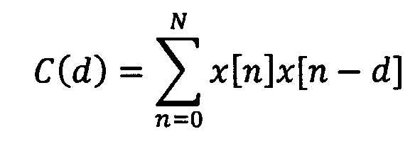
일반적으로, SNR은 샘플씩 (오디오 신호와 같은) 원래의 오디오 신호와 처리된 오디오 신호를 비교한다. 이의 목표는 입력 파형을 재생하는 파형 코더의 왜곡을 측정하는 것이다. 도 5a에 도시된 바와 같이 SNR이 계산될 수 있으며, 여기서 x(i) 및 y(i)는 i에 의해 인덱싱되는 원래의 샘플 및 처리된 샘플이고, N은 샘플의 총수이다. 전체 신호에서 작업하는 대신에 세그먼트 SNR은 5ms와 같이 1ms 내지 10ms와 같은 짧은 세그먼트의 SNR 값의 평균을 계산한다. 도 5b에 도시된 바와 같이 SNR이 계산될 수 있으며, 여기서 N 및 M은 각각 세그먼트 길이 및 세그먼트의 수이다B.Generally, the SNR compares the processed audio signal with the original audio signal (such as an audio signal), one sample at a time. Its goal is to measure the distortion of the waveform coder that reproduces the input waveform. As shown in FIG. 5A, the SNR can be computed, where x (i) and y (i) are the original and processed samples indexed by i and N is the total number of samples. Instead of working on the whole signal, the segment SNR computes the average of the SNR values of the short segments such as 1 ms to 10 ms, such as 5 ms. As shown in FIG. 5B, the SNR can be calculated, where N and M are the segment length and the number of segments, respectively.
본 발명의 실시예에서, 오디오 신호의 부분은 오디오 신호를 윈도잉함으로써 획득되는 오디오 신호의 프레임을 나타내고, 적절한 인코딩 알고리즘의 선택은 오디오 신호를 윈도잉함으로써 획득되는 복수의 연속 프레임에 대해 수행된다. 다음의 명세서에서, 오디오 신호와 관련하여, 용어 "부분" 및 "프레임"은 교환 가능한 방식으로 사용된다. 실시예에서, 각각의 프레임은 서브프레임으로 분할되고, 세그먼트 SNR은 각각의 서브프레임에 대한 SNR을 계산함으로써 각각의 프레임에 대하여 추정되고, dB로 변환되며, dB의 서브프레임 SNR의 평균을 계산한다.In an embodiment of the invention, the portion of the audio signal represents a frame of the audio signal obtained by windowing the audio signal, and the selection of a suitable encoding algorithm is performed for a plurality of consecutive frames obtained by windowing the audio signal. In the following specification, in relation to an audio signal, the terms "part" and "frame" are used in an interchangeable manner. In an embodiment, each frame is divided into sub-frames, and the segment SNR is estimated for each frame by calculating the SNR for each sub-frame, converted to dB, and the average of the sub-frame SNRs in dB is calculated .
따라서, 실시예에서, 입력 오디오 신호와 디코딩된 오디오 신호 사이에는 추정되는 (세그먼트) SNR이 없지만, 가중된 입력 오디오 신호와 가중된 디코딩된 오디오 신호 사이의 (세그먼트) SNR은 추정된다. 이러한 (세그먼트) SNR이 관계되는 한, AMR-WB+ 표준(국제 표준 3GPP TS 26.290 V6.1.0 2004-12)의 챕터 5.2.3에 대한 참조가 행해질 수 있다.Thus, in the embodiment, there is no estimated (segment) SNR between the input audio signal and the decoded audio signal, but the (segment) SNR between the weighted input audio signal and the weighted decoded audio signal is estimated. A reference to Chapter 5.2.3 of the AMR-WB + standard (international standard 3GPP TS 26.290 V6.1.0 2004-12) can be made so long as this (segment) SNR is concerned.
본 발명의 실시예에서, 각각의 품질 측정치는 가중된 오디오 신호의 부분의 에너지와 각각의 알고리즘에 의해 신호 부분을 인코딩할 때 도입되는 추정된 왜곡에 기초하여 추정되며, 제 1 및 제 2 추정기는 가중된 오디오 신호의 에너지에 따라 추정된 왜곡을 결정하도록 구성된다. In an embodiment of the present invention, each quality measure is estimated based on the energy of the portion of the weighted audio signal and the estimated distortion introduced when encoding the signal portion by each algorithm, and the first and second estimators And to determine the estimated distortion according to the energy of the weighted audio signal.
본 발명의 실시예에서, 오디오 신호의 부분을 양자화할 때 제 1 인코딩 알고리즘에 사용되는 양자화기에 의해 도입되는 추정된 양자화 왜곡은 결정되고, 제 1 품질 측정치는 가중된 오디오 신호의 부분의 에너지와 추정된 양자화 왜곡에 기초하여 결정된다. 이러한 실시예에서, 오디오 신호의 부분은 제 1 인코딩 알고리즘에 사용된 엔트로피 인코더 및 양자화기로 인코딩될 때 주어진 타겟 비트레이트를 생성하도록 오디오 신호의 부분에 대한 글로벌 이득은 추정될 수 있고, 추정된 양자화 왜곡은 추정된 글로벌 이득에 기초하여 결정된다. 이러한 실시예에서, 추정된 양자화 왜곡은 추정된 이득의 전력에 기초하여 결정될 수 있다. 제 1 인코딩 알고리즘에 사용된 양자화가 균일한 스칼라 양자화기인 경우, 제 1 추정기는 식 D = G*G/12를 사용하여 추정된 양자화 왜곡을 결정하도록 구성될 수 있으며, 여기서 D는 추정된 양자화 왜곡이고, G는 추정된 글로벌 이득이다. 제 1 인코딩 알고리즘이 다른 양자화기를 이용하는 경우에, 양자화 왜곡은 서로 다른 방식으로 글로벌 이득으로부터 결정할 수 있다.In an embodiment of the invention, the estimated quantization distortion introduced by the quantizer used in the first encoding algorithm when quantizing the portion of the audio signal is determined, and the first quality measure is estimated with the energy of the portion of the weighted audio signal Based quantization distortion. In this embodiment, the global gain for a portion of the audio signal can be estimated to produce a given target bit rate when the portion of the audio signal is encoded into the entropy encoder and quantizer used in the first encoding algorithm, and the estimated quantization distortion Is determined based on the estimated global gain. In this embodiment, the estimated quantization distortion can be determined based on the estimated power of the gain. If the quantization used in the first encoding algorithm is a uniform scalar quantizer, the first estimator may be configured to determine the estimated quantization distortion using the equation D = G * G / 12, where D is the estimated quantization distortion And G is the estimated global gain. In the case where the first encoding algorithm uses a different quantizer, the quantization distortion can be determined from the global gain in a different way.
발명자는 TCX 알고리즘과 같은 제 1 인코딩 알고리즘을 사용하여 오디오 신호의 부분을 인코딩 및 디코딩할 경우에 획득될 수 있는 세그먼트 SNR과 같은 품질 측정치가 이의 임의의 조합으로 상술한 특징을 이용하여 적절한 방식으로 추정될 수 있다는 것을 인식하였다. The inventors have found that quality measurements, such as segment SNR, which can be obtained when encoding and decoding portions of an audio signal using a first encoding algorithm, such as the TCX algorithm, are estimated in an appropriate manner using any of the above- .
본 발명의 실시예에서, 제 1 품질 측정치는 세그먼트 SNR이고, 세그먼트 SNR은 가중된 오디오 신호의 대응하는 서브 부분의 에너지와 추정된 양자화 왜곡에 기초하여 오디오 신호의 부분의 복수의 서브 부분의 각각과 관련되는 추정된 SNR을 계산하고, 가중된 오디오 신호의 부분에 대한 추정된 세그먼트 SNR을 획득하기 위해 가중된 오디오 신호의 부분의 서브 부분과 관련된 SNR의 평균을 계산함으로써 추정된다.In an embodiment of the present invention, the first quality measurement is a segment SNR, and the segment SNR is based on the energy of the corresponding sub-portion of the weighted audio signal and the estimated quantization distortion, Is estimated by calculating the associated estimated SNR and calculating an average of the SNR associated with the sub-portion of the portion of the weighted audio signal to obtain an estimated segment SNR for the portion of the weighted audio signal.
본 발명의 실시예에서, 오디오 신호의 부분을 인코딩하기 위해 적응 코드북을 사용할 때 제 2 인코딩 알고리즘에 사용된 적응 코드북에 의해 도입되는 추정된 적응 코드북 왜곡은 결정되고, 제 2 품질 측정치는 가중된 오디오 신호의 부분의 에너지 및 추정된 적응 코드북 왜곡에 기초하여 추정된다.In an embodiment of the present invention, the estimated adaptive codebook distortion introduced by the adaptive codebook used in the second encoding algorithm when using the adaptive codebook to encode a portion of the audio signal is determined, and the second quality measure is weighted audio Is estimated based on the energy of the portion of the signal and the estimated adaptive codebook distortion.
이러한 실시예에서, 오디오 신호의 부분의 복수의 서브 부분의 각각에 대해, 적응 코드북은 전처리 스테이지에서 결정된 피치 지연에 의해 과거로 시프트되는 가중된 오디오 신호의 서브 부분의 버전에 기초하여 근사화될 수 있고, 적응 코드북 이득은 가중된 오디오 신호의 부분의 서브 부분과 근사화된 적응 코드북 사이의 에러가 최소화되도록 추정될 수 있으며, 추정된 적응 코드북 왜곡은 가중된 오디오 신호의 부분의 서브 부분과 적응 코드북 이득에 의해 스케일링된 근사화된 적응 코드북 사이의 에러의 에너지에 기초하여 결정될 수 있다.In this embodiment, for each of the plurality of sub-portions of the portion of the audio signal, the adaptive codebook may be approximated based on the version of the sub-portion of the weighted audio signal shifted in the past by the pitch delay determined in the preprocessing stage , The adaptive codebook gain can be estimated such that the error between the sub-portion of the portion of the weighted audio signal and the approximated adaptive codebook is minimized, and the estimated adaptive codebook distortion can be estimated from the sub- Lt; / RTI > can be determined based on the energy of the error between the approximated adaptive codebooks scaled by the approximated adaptive codebook.
본 발명의 실시예에서, 오디오 신호의 부분의 각각의 서브 부분에 대해 결정되는 추정된 적응 코드북 왜곡은 제 2 인코딩 알고리즘에서 혁신적인 코드북에 의해 달성되는 왜곡의 감소를 고려하기 위해 일정한 인수만큼 감소될 수 있다.In an embodiment of the present invention, the estimated adaptive codebook distortion determined for each sub-portion of the portion of the audio signal may be reduced by a factor of a factor to account for the reduction in distortion achieved by the innovative codebook in the second encoding algorithm have.
본 발명의 실시예에서, 제 2 품질 측정치는 세그먼트 SNR이고, 세그먼트 SNR은 가중된 오디오 신호의 대응하는 서브 부분의 에너지와 추정된 적응 코드북 왜곡에 기초하여 각각의 서브 부분과 관련되는 추정된 SNR을 계산하고, 추정된 세그먼트 SNR을 획득하기 위해 서브 부분과 관련된 SNR의 평균을 계산함으로써 추정된다.In an embodiment of the invention, the second quality measure is a segment SNR, and the segment SNR is the estimated SNR associated with each sub-portion based on the energy of the corresponding sub-portion of the weighted audio signal and the estimated adaptive codebook distortion And calculating an average of SNRs associated with the sub-portion to obtain an estimated segment SNR.
본 발명의 실시예에서, 적응 코드북은 전처리 스테이지에서 결정된 피치 지연에 의해 과거로 시프트되는 가중된 오디오 신호의 부분의 버전에 기초하여 근사화될 수 있고, 적응 코드북 이득은 가중된 오디오 신호의 부분과 근사화된 적응 코드북 사이의 에러가 최소화되도록 추정되며, 추정된 적응 코드북 왜곡은 가중된 오디오 신호의 부분 적응 코드북 이득에 의해 스케일링되는 근사화된 적응 코드북 사이의 에너지에 기초하여 결정된다. 따라서, 추정된 적응 코드북 왜곡은 낮은 복잡도로 결정될 수 있다.In an embodiment of the present invention, the adaptive codebook may be approximated based on the version of the portion of the weighted audio signal shifted in the past by the pitch delay determined in the preprocessing stage, and the adaptive codebook gain may be approximated to the portion of the weighted audio signal And the estimated adaptive codebook distortion is determined based on the energy between the approximated adaptive codebook scaled by the partial adaptive codebook gain of the weighted audio signal. Thus, the estimated adaptive codebook distortion can be determined to have a low complexity.
발명자는 ACELP 알고리즘과 같은 제 2 인코딩 알고리즘을 사용하여 오디오 신호의 부분을 인코딩 및 디코딩할 경우에 획득될 수 있는 세그먼트 SNR과 같은 품질 측정치가 이의 임의의 조합으로 상술한 특징을 이용하여 적절한 방식으로 추정될 수 있다는 것을 인식하였다. The inventors have found that quality measurements, such as segment SNR, which can be obtained when encoding and decoding portions of an audio signal using a second encoding algorithm, such as the ACELP algorithm, are estimated in an appropriate manner using any of the above- .
본 발명의 실시예에서, 히스테리시스 메커니즘은 추정된 품질 측정치를 비교할 시에 사용된다. 이것은 어떤 알고리즘이 보다 안정적으로 사용될 수 있는지를 결정할 수 있다. 히스테리시스 메커니즘은 추정된 품질 측정치(예를 들어 이 사이의 차이)와, 이전의 결정에 대한 통계, 시간적 고정 프레임의 수, 프레임 내의 과도 프레임과 같은 다른 파라미터에 의존할 수 있다. 이러한 히스테리시스 메커니즘이 관계하는 한, 예를 들어, WO 2012/110448 A1에 대한 참조가 행해질 수 있다.In an embodiment of the invention, the hysteresis mechanism is used to compare the estimated quality measurements. This can determine which algorithms can be used more reliably. The hysteresis mechanism may depend on the estimated quality measurements (e.g., the difference between them) and other parameters such as statistics for previous decisions, the number of temporal fixed frames, and transient frames within a frame. As far as this hysteresis mechanism is concerned, for example, a reference to WO 2012/110448 A1 can be made.
본 발명의 실시예에서, 오디오 신호를 코딩하기 위한 인코더는 장치(10), 제 1 인코딩 알고리즘을 수행하기 위한 스테이지 및 제 2 인코딩 알고리즘을 수행하기 위한 스테이지를 포함하며, 인코더는 제어기(16)에 의한 선택에 따라 제 1 인코딩 알고리즘 또는 제 2 인코딩 알고리즘을 이용하여 오디오 신호의 부분을 인코딩하도록 구성된다. 본 발명의 실시예에서, 인코딩 및 디코딩하기 위한 시스템은 오디오 신호의 부분의 인코딩된 버전과, 지시된 알고리즘을 이용하여 오디오 신호의 부분을 인코딩하고 오디오 신호의 부분의 인코딩된 버전을 디코딩하는데 사용되는 알고리즘의 지시를 수신하도록 구성된 인코더 및 디코더를 포함한다. In an embodiment of the present invention, an encoder for coding an audio signal includes a
도 1에 도시되고 (필터(2)를 제외하고) 상술한 바와 같은 개방 루프 모드 선택은 이전의 출원 PCT/EP2014/051557에 설명되어 있다. 이러한 알고리즘은 프레임 단위로 ACELP 및 TCX와 같은 두 모드 사이에서 선택하는데 사용된다. 이러한 선택은 ACELP 및 TCX의 모두의 세그먼트 SNR의 추정에 기초할 수 있다. 최고 추정되는 세그먼트 SNR을 가진 모드가 선택된다. 선택적으로, 히스테리시스 메커니즘은 보다 강력한 선택을 제공하기 위해 사용될 수 있다. ACELP의 세그먼트 SNR은 적응 코드북 왜곡의 근사치와 혁신적인 코드북 왜곡의 근사치를 이용하여 추정될 수 있다.The open loop mode selection shown in FIG. 1 (except for filter 2) as described above is described in the prior application PCT / EP2014 / 051557. These algorithms are used to select between two modes, such as ACELP and TCX, on a frame-by-frame basis. This selection may be based on an estimate of the segment SNR of both ACELP and TCX. The mode with the highest estimated segment SNR is selected. Optionally, the hysteresis mechanism may be used to provide a more robust selection. The segment SNR of the ACELP can be estimated using an approximation of the adaptive codebook distortion and an approximation of the innovative codebook distortion.
적응 코드북은 피치 분석 알고리즘에 의해 추정된 피치 지연을 이용하여 가중된 신호 도메인에서 근사화될 수 있다. 왜곡은 최적의 이득을 추정하는 가중된 신호 도메인에서 계산될 수 있다. 그 후, 왜곡은 일정한 인수만큼 감소되어, 혁신적인 코드북 왜곡에 근사화할 수 있다. TCX의 세그먼트 SNR은 실제 TCX 인코더의 간소화된 버전을 사용하여 추정될 수 있다. 입력 신호는 먼저 MDCT로 변형되고, 그 다음 가중된 LPC 필터를 사용하여 형성할 수 있다. 마지막으로, 왜곡은 글로벌 이득 및 글로벌 이득 추정기를 사용하여 가중된 MDCT 도메인에서 추정될 수 있다.The adaptive codebook can be approximated in the weighted signal domain using the pitch delay estimated by the pitch analysis algorithm. The distortion can be computed in the weighted signal domain that estimates the optimal gain. Then, the distortion is reduced by a constant factor, which can approximate the innovative codebook distortion. The segment SNR of the TCX can be estimated using a simplified version of the actual TCX encoder. The input signal may first be transformed to MDCT, and then formed using a weighted LPC filter. Finally, the distortion can be estimated in the weighted MDCT domain using the global gain and global gain estimator.
이전의 출원에서 설명된 바와 같은 이러한 개방 루프 모드 선택 알고리즘은 시간의 대부분을 예상된 결정에 제공하고, 음성형 및 과도형 신호에서 ACELP를 선택하며, 음악형 및 잡음형 신호에서 TCX를 선택한다는 것이 밝혀졌다. 그러나, 발명자는 ACELP이 때때로 일부 고조파 음악 신호에사 선택되는 경우가 발생할 수 있다는 것을 인식하였다. 이러한 신호에서 적응 코드북은 일반적으로 고조파 신호의 높은 예측 가능성으로 인해 높은 예측 이득을 가지고, 낮은 왜곡을 생성시켜 TCX보다 더 높은 세그먼트 SNR을 생성시킨다. 그러나, TCX는 대부분 고조파 음악 신호에서 더 나은 소리를 내며, 그래서 TCX는 이러한 경우에 바람직하다.This open-loop mode selection algorithm as described in the prior application provides most of the time to the expected decision, chooses ACELP in the speech and transient signals, and chooses TCX in the musical and noise-like signals It turned out. However, the inventors have recognized that ACELP may occasionally be selected for some harmonic music signals. In such a signal, the adaptive codebook generally has a high prediction gain due to the high predictability of the harmonic signal and produces a low distortion, resulting in a higher segment SNR than the TCX. However, TCX mostly sounds better in harmonic music signals, so TCX is preferable in this case.
따라서, 본 발명은 고조파를 감소시키기 위해 필터링되는 입력 신호의 버전을 사용하여 제 1 품질 측정치로서 SNR 또는 세그먼트 SNR의 추정을 수행하도록 제안한다. 따라서, 고조파 음악 신호에 대한 개선된 모드 선택이 획득될 수 있다.Accordingly, the present invention proposes to perform an estimate of SNR or segment SNR as a first quality measure using a version of the input signal that is filtered to reduce harmonics. Thus, an improved mode selection for the harmonic music signal can be obtained.
일반적으로, 고조파를 감소시키기 위한 임의의 적절한 필터가 사용될 수 있다. 본 발명의 실시예에서, 필터는 장기 예측 필터이다. 장기 예측 필터의 간단한 일례는 다음과 같다.In general, any suitable filter for reducing harmonics can be used. In an embodiment of the present invention, the filter is a long term prediction filter. A simple example of the long term prediction filter is as follows.
F(z) = 1 - g ·z-T F (z) = 1 - gz-T
여기서 필터 파라미터는 오디오 신호로부터 결정되는 이득 "g" 및 피치 지연 "T"이다. Where the filter parameters are the gain "g" and the pitch delay "T" determined from the audio signal.
본 발명의 실시예는 TCX 세그먼트 SNR 추정에서 MDCT 분석 전에 오디오 신호에 적용되는 장기 예측 필터에 기초한다. 장기 예측 필터는 MDCT 분석 전에 입력 신호의 고조파의 진폭을 감소시킨다. 결과적으로 가중된 MDCT 도메인에서의 왜곡은 감소된다. TCX의 추정된 세그먼트 SNR은 증가되고, 마지막으로 TCX는 고조파 음악 신호에 더 자주 선택된다.Embodiments of the present invention are based on long term prediction filters applied to audio signals prior to MDCT analysis in TCX segment SNR estimation. The long term prediction filter reduces the amplitude of the harmonics of the input signal before MDCT analysis. As a result, the distortion in the weighted MDCT domain is reduced. The estimated segment SNR of the TCX is increased, and finally the TCX is selected more often for the harmonic music signal.
본 발명의 실시예에서, 장기 예측 필터의 전달 함수는 피치 지연의 정수 부분과 피치 지연의 소수 부분에 따른 다중 탭 필터를 포함한다. 이것은 정수 부분이 정상 샘플링 레이트 프레임워크(z-Tint)에만 사용되기 때문에 효율적인 구현을 허용한다. 동시에, 다중 탭 필터의 소수 부분의 사용으로 인한 높은 정밀도가 달성될 수 있다. 다중 탭 필터의 소수 부분을 고려함으로써, 고조파의 에너지의 제거는 고조파에 가까운 부분의 에너지의 제거가 회피될 동안에 달성될 수 있다.In an embodiment of the invention, the transfer function of the long term prediction filter comprises a multi-tap filter according to the integer part of the pitch delay and the fractional part of the pitch delay. This allows efficient implementation because the integer part is only used for the normal sampling rate framework (z -Tint ). At the same time, high precision due to the use of the fractional part of the multi-tap filter can be achieved. By considering the fractional part of the multi-tap filter, the elimination of the harmonic energy can be achieved while the elimination of the energy near the harmonic is avoided.
본 발명의 실시예에서, 장기 예측 필터는 다음과 같이 설명된다:In an embodiment of the present invention, the long term prediction filter is described as follows:
P(z) = 1 - βgB(z, Tfr)z-Tint P (z) = 1 -? GB (z, T fr ) z -Tint
여기서, Tint 및 Tfr은 피치 지연의 정수 및 소수 부분이고, g는 이득이고, β는 장기 예측 필터의 강도를 제어하는 가중치이며, B(z, Tfr)는 계수가 피치 지연의 소수 부분에 의존하는 FIR 저역 통과 필터이다. 이러한 장기 예측 필터의 실시예에 대한 더 상세한 사항은 아래에서 설명될 것이다. Here, T int and T fr is the integer and fractional part of the pitch delay, g is the gain, and, β is a weight for controlling the intensity of the long term prediction filter, B (z, T fr) is the fractional part of the coefficient of the pitch lag Lt; RTI ID = 0.0 > FIR < / RTI > Further details of embodiments of such long term prediction filters will be described below.
피치 지연 및 이득은 프레임 단위로 추정될 수 있다.The pitch delay and gain can be estimated on a frame-by-frame basis.
예측 필터는 하나 이상의 조화도 측정치(예를 들어 정규화 상관 관계 또는 예측 이득) 및/또는 하나 이상의 시간적 구조 측정치(예를 들어 시간적 평탄도 측정치 또는 에너지 변화)의 조합에 기초하여 비활성화될 수 있다(이득=0).The prediction filter may be deactivated based on a combination of one or more harmonic measurements (e.g., normalized correlation or predictive gain) and / or one or more temporal structural measurements (e.g., temporal flatness measure or energy change) = 0).
필터는 프레임 단위로 입력 오디오 신호에 적용될 수 있다. 필터 파라미터가한 프레임에서 다음 프레임으로 변경하는 경우, 불연속성은 두 프레임 사이의 경계에서 도입될 수 있다. 실시예에서, 장치는 필터에 의해 생성된 오디오 신호의 불연속성을 제거하기 위한 유닛을 더 포함한다. 가능한 불연속성을 제거하기 위해, 임의의 기술은 US5012517, EP0732687A2, US5999899A 또는 US7353168B2에 기재된 것과 유사한 기술과 같이 사용될 수 있다. 가능한 불연속성을 제거하기 위한 다른 기술은 아래에 설명된다.The filter may be applied to the input audio signal on a frame-by-frame basis. If the filter parameter changes from one frame to the next, discontinuity can be introduced at the boundary between two frames. In an embodiment, the apparatus further comprises a unit for eliminating the discontinuity of the audio signal produced by the filter. To eliminate possible discontinuities, any technique may be used such as a technique similar to that described in US5012517, EP0732687A2, US5999899A or US7353168B2. Other techniques for eliminating possible discontinuities are described below.
도 3을 상세히 참조하여 제 1 추정기(12) 및 제 2 추정기(14)의 실시예를 설명하기 전에, 인코더(20)의 실시예는 도 2를 참조하여 설명한다.Before describing an embodiment of the
인코더(20)는 제 1 추정기(12), 제 2 추정기(14), 제어기(16), 전처리 유닛(22), 스위치(24), TCX 알고리즘을 수행하도록 구성된 제 1 인코더 스테이지(26), ACELP 알고리즘을 수행하도록 구성된 제 2 인코더 스테이지(28), 및 출력 인터페이스(30)를 포함한다. 전처리 유닛(22)은 공통 USAC 인코더의 부분일 수 있고, LPC 계수, 가중된 LPC 계수, 가중된 오디오 신호, 및 피치 지연의 세트를 출력하도록 구성될 수 있다. 이러한 파라미터의 모두는 두 인코딩 알고리즘, 즉 TCX 알고리즘 및 ACELP 알고리즘에 사용되는 것이 주목되어야 한다. 따라서, 이러한 파라미터는 추가적으로 개방 루프 모드 결정을 위해 계산될 필요가 없다. 개방 루프 모드 결정에서 이미 계산된 파라미터를 사용하는 이점은 복잡도를 절약한다.The
도 2에 도시된 바와 같이, 장치는 고조파 감소 필터(2)를 포함한다. 장치는 하나 이상의 조화도 측정치(예를 들어 정규화 상관 관계 또는 예측 이득) 및/또는 하나 이상의 시간적 구조 측정치(예를 들어 시간적 평탄도 측정치 또는 에너지 변화)의 조합에 기초하여 고조파 감소 필터(2)를 비활성화하기 위한 선택적 비활성화 유닛(4)을 더 포함한다. 장치는 오디오 신호의 필터링된 버전으로부터 불연속성을 제거하기 위한 선택적 불연속성 제거 유닛(6)을 포함한다. 게다가, 장치는 선택적으로 고조파 감소 필터(2)의 필터 파라미터를 추정하기 위한 유닛(8)을 포함한다. 도 2에서, 이러한 구성 요소(2, 4, 6 및 8)는 제 1 추정기(12)의 부분인 것으로서 도시된다. 이러한 구성 요소는 제 1 추정기에서 외부 또는 별개로 구현될 수 있고, 오디오 신호의 필터링된 버전을 제 1 추정기에 제공하도록 구성될 수 있다는 것은 말할 것도 없다.As shown in FIG. 2, the apparatus includes a
입력 오디오 신호(40)는 입력 라인 상에 제공된다. 입력 오디오 신호(40)는 제 1 추정기(12), 전처리 유닛(22) 및 두 인코더 스테이지(26, 28)에 인가된다. 제 1 추정기(12)에서, 입력 오디오 신호(40)는 필터(2)에 인가되고, 입력 오디오 신호의 필터링된 버전은 제 1 품질 측정치를 추정하는데 사용된다. 필터가 비활성화 유닛(4)에 의해 비활성화되는 경우에, 입력 오디오 신호(40)는 입력 오디오 신호의 필터링된 버전보다는 제 1 품질 측정치를 추정하는데 사용된다. 전처리 유닛(22)은 LPC 계수와 가중된 LPC 계수(42)를 유도하고, 가중된 오디오 신호(44)를 획득하기 위해 가중된 LPC 계수(42)로 오디오 신호(40)를 필터링하도록 통상적인 방식으로 입력 오디오 신호를 처리한다. 전처리 유닛(22)은 가중된 LPC 계수(42), 가중된 오디오 신호(44) 및 피치 지연(48)의 세트를 출력한다. 당업자에 의해 이해되는 바와 같이, 가중된 LPC 계수(42) 및 가중된 오디오 신호(44)는 프레임 또는 서브프레임으로 세그먼트될 수 있다. 세그멘테이션은 적절한 방식으로 오디오 신호를 윈도잉함으로써 획득될 수 있다.An
대안적 실시예에서, 오디오 신호의 필터링된 버전에 기초하여 가중된 LPC 계수 및 가중된 오디오 신호를 생성하도록 구성되는 전처리기가 제공될 수 있다. 그 후, 오디오 신호의 필터링된 버전에 기초하는 가중된 LPC 계수 및 가중된 오디오 신호는 가중된 LPC 계수(42) 및 가중된 오디오 신호(44)보다는 제 1 품질 측정치를 추정하기 위해 제 1 추정기에 인가된다.In an alternative embodiment, a preprocessor may be provided that is configured to generate a weighted LPC coefficient and a weighted audio signal based on a filtered version of the audio signal. The weighted LPC coefficients and the weighted audio signal, which are based on the filtered version of the audio signal, are then fed to a first estimator to estimate a first quality measure rather than a
본 발명의 실시예에서, 양자화된 LPC 계수 또는 양자화된 가중된 LPC 계수가 사용될 수 있다. 따라서, 용어 "LPC 계수"는 또한 "양자화된 LPC 계수"를 포함하도록 의도되고, 용어 "가중된 LPC 계수"는 또한 "가중된 양자화된 LPC 계수"를 포함하도록 의도되는 것으로 이해되어야 한다. 이런 점에서, USAC의 TCX 알고리즘은 MCDT 스펙트럼을 형성하기 위해 양자화된 가중된 LPC 계수를 사용한다는 점을 주목할 필요가 있다.In an embodiment of the present invention, a quantized LPC coefficient or a quantized weighted LPC coefficient may be used. Thus, the term "LPC coefficient" is also intended to include "quantized LPC coefficients ", and the term" weighted LPC coefficients "is also intended to include" weighted quantized LPC coefficients. In this regard, it should be noted that USAC's TCX algorithm uses quantized weighted LPC coefficients to form the MCDT spectrum.
제 1 추정기(12)는 오디오 신호(40), 가중된 LPC 계수(42) 및 가중된 오디오 신호(44)를 수신하고, 이에 기초하여 제 1 품질 측정치(46)를 추정하며, 제 1 품질 측정치를 제어기(16)로 출력한다. 제 2 추정기(14)는 가중된 오디오 신호(44) 및 피치 지연(48)의 세트를 수신하고, 이에 기초하여 제 2 품질 측정치(50)를 추정하며, 제 2 품질 측정치(50)를 제어기(16)로 출력한다. 당업자에게는 알려져 있는 바와 같이, 가중된 LPC 계수(42), 가중된 오디오 신호(44) 및 피치 지연(48)의 세트는 이미 이전의 모듈(즉 전처리 유닛(22))에서 계산되며, 따라서 비용 없이 이용 가능하다.The
제어기는 수신된 품질 측정치의 비교에 기초하여 TCX 알고리즘 또는 ACELP 알고리즘을 선택하도록 결정한다. 상술한 바와 같이, 제어기는 어떤 알고리즘을 사용할지를 결정할 시에 히스테리시스 메커니즘을 사용할 수 있다. 제 1 인코더 스테이지(26) 또는 제 2 인코더 스테이지(28)의 선택은 제어기(16)에 의해 출력되는 제어 신호(52)에 의해 제어되는 스위치(24)에 의해 도 2에 개략적으로 도시된다. 제어 신호(52)는 제 1 인코더 스테이지(26)가 사용되는지 제 2 인코더 스테이지(28)가 사용되는지를 나타낸다. 제어 신호(52)에 기초하여, 도 2에서 화살표(54)로 개략적으로 나타내고, 적어도 LPC 계수, 가중된 LPC 계수, 오디오 신호, 가중된 오디오 신호, 피치 지연의 세트를 포함하는 필요한 신호는 제 1 인코더 스테이지(26) 또는 제 2 인코더 스테이지(28)에 인가된다. 선택된 인코더 스테이지는 관련된 인코딩 알고리즘을 적용하고, 인코딩된 표현(56)을 출력 인터페이스(30)로 출력한다. 출력 인터페이스(30)는 다른 데이터 중에서 인코딩된 표현(56 또는 58), LPC 계수 또는 가중된 LPC 계수, 선택된 인코딩 알고리즘에 대한 파라미터 밀 선택된 인코딩 알고리즘에 관한 정보를 포함할 수 있는 인코딩된 오디오 신호(60)를 출력하도록 구성될 수 있다.The controller decides to select the TCX algorithm or the ACELP algorithm based on the comparison of the received quality measures. As described above, the controller can use a hysteresis mechanism in determining which algorithm to use. The selection of either the
제 1 및 제 2 품질 측정치가 가중된 신호 영역에서의 세그먼트 SNR인 제 1 및 제 2 품질 측정치를 추정하기 위한 특정 실시예는 이제 도 3을 참조하여 설명된다. 도 3은 제 1 추정기(12) 및 제 2 추정기(14)와, 각각의 추정 단계별을 나타내는 흐름도의 형태로 이의 기능을 도시한다.A specific embodiment for estimating the first and second quality measurements where the first and second quality measurements are segment SNRs in the weighted signal region is now described with reference to FIG. FIG. 3 shows the functions of the
TCXTCX 의 of 세그먼트Segment SNRSNR 의 추정Estimation of
제 1(TCX) 추정기는 오디오 신호(40)(입력 신호), 가중된 LPC 계수(42) 및 가중된 오디오 신호(44)를 입력으로서 수신한다. 오디오 신호(40)의 필터링된 버전은 단계(98)에서 생성된다. 오디오 신호(40)의 필터링된 버전에서, 고조파는 감소되거나 억제된다.The first (TCX) estimator receives as inputs the audio signal 40 (input signal), the
오디오 신호(40)는 하나 이상의 조화도 측정치(예를 들어 정규화 상관 관계 또는 예측 이득) 및/또는 하나 이상의 시간적 구조 측정치(예를 들어 시간적 평탄도 측정치 또는 에너지 변화)를 결정하기 위해 분석될 수 있다. 이러한 측정치 중 하나 또는 이러한 측정치의 조합에 기초하여 필터(2) 및 따라서 필터링(98)이 비활성화될 수 있다. 필터링(98)이 비활성화되면, 제 1 품질 측정치의 추정은 이의 필터링된 버전보다는 오디오 신호(40)를 사용하여 수행된다.The
본 발명의 실시예에서, (도 3에 도시되지 않은) 불연속성을 제거하는 단계는 필터링(98)으로부터 생성할 수 있는 오디오 신호의 불연속성을 제거하기 위해 필터링(98)을 따를 수 있다.In an embodiment of the present invention, removing the discontinuity (not shown in FIG. 3) may follow filtering 98 to remove the discontinuity of the audio signal that may be generated from the
단계(100)에서, 오디오 신호(40)의 필터링된 버전은 윈도잉된다. 윈도잉은 10ms의 낮은 오버랩 사인 윈도우로 발생할 수 있다. 과거 프레임이 ACELP인 경우, 블록의 크기는 5ms만큼 증가될 수 있고, 윈도우의 좌측은 직사각형일 수 있고, ACELP 합성 필터의 윈도잉된 제로 임펄스 응답은 윈도잉된 입력 신호로부터 제거될 수 있다. 이것은 TCX 알고리즘에서 행해지는 것과 유사하다. 오디오 신호의 부분을 나타내는 오디오 신호(40)의 필터링된 버전의 프레임은 단계(100)로부터 출력된다.At
단계(102)에서, 윈도잉된 오디오 신호, 즉 생성된 프레임은 MDCT(수정된 이산 코사인 변환)로 변환된다. 단계(104)에서 스펙트럼 형상화(spectrum shaping)는 가중된 LPC 계수로 MDCT 스펙트럼를 형상화함으로써 수행된다.In
단계(106)에서, 글로벌 이득 G는 이득 G로 양자화되는 가중된 스펙트럼이 엔트로피 코더, 예를 들어 산술 코더로 인코딩될 때 주어진 타겟 R을 생성하도록 추정된다. 용어 "글로벌 이득"은 하나의 이득이 전체 프레임에 대해 결정되기 때문에 사용된다.At
글로벌 이득 추정의 구현의 일례가 이제 설명된다. 이러한 글로벌 이득 추정은 TCX 인코딩 알고리즘이 산술 인코더를 가진 스칼라 양자화기를 사용하는 실시예에 적절하다는 것이 주목되어야 한다. 산술 인코더를 가진 이러한 스칼라 양자화기는 MPEG USAC 표준에서 추정된다.An example of an implementation of global gain estimation is now described. It should be noted that this global gain estimation is appropriate for embodiments in which the TCX encoding algorithm uses a scalar quantizer with an arithmetic encoder. Such scalar quantizers with arithmetic encoders are estimated in the MPEG USAC standard.
초기화reset
첫째로, 이득 추정에 사용된 변수는 다음에 의해 초기화된다.First, the variable used for gain estimation is initialized by
1. Set en[i] = 9.0 + 10.0*log10(c[4*i+0] + c[4*i+1] + c[4*i+2] + c[4*i+3]), 1) + c [4 * i + 2] + c [4 * i + 3] ,
여기서, 0<=i<L/4, c[] 는 양자화하기 위한 계수의 벡터이고, L은 c[]의 길이이다. Where 0 <= i <L / 4, c [] is a vector of coefficients for quantization, and L is the length of c [].
2. Set fac = 128, offset = fac 및 target = 임의의 값(예를 들어 1000)2. Set fac = 128, offset = fac and target = any value (for example 1000)
반복repeat
그 후, 연산의 다음의 블록은 NITER 번 수행된다(예를 들어 여기서, NITER = 10).The next block of the operation is then performed NITER times (e.g., where NITER = 10).
1. fac = fac/21. fac = fac / 2
2. offset = offset - fac2. offset = offset - fac
3. ener = 03. ener = 0
4. 모든 i에 대해, 0<=i<L/4은 다음을 수행한다:4. For all i, 0 <= i <L / 4 does the following:
en[i]-offset > 3.0이면, ener = ener + en[i]-offset If en [i] -offset> 3.0, ener = ener + en [i] -offset
5. ener > target이면, offset = offset + fac5. If ener> target, offset = offset + fac
반복의 결과치는 오프셋 값이다. 반복 후, 글로벌 이득은 G = 10^(offset/20)으로 추정된다.The result of the iteration is an offset value. After iteration, the global gain is estimated to be G = 10 ^ (offset / 20).
글로벌 이득이 추정되는 특정 방식은 양자화기 및 사용된 엔트로피 코더에 따라 달라질 수 있다. MPEG USAC 표준에서는, 산술 인코더를 가진 스칼라 양자화기가 추정된다. 다른 TCX 접근 방식은 서로 다른 양자화기를 사용할 수 있고, 이러한 서로 다른 양자화기에 대한 글로벌 이득을 추정하는 방법을 당업자는 이해한다. 예를 들면, AMR-WB+ 표준은 RE8 격자 양자화기가 사용되는 것으로 추정한다. 이러한 양자화기에 대해, 3GPP TS 26.290 V6.1.0 2004-12의 페이지 34에서 챕터 5.3.5.7에 기재된 바와 같이 글로벌 이득의 추정법이 추정될 수 있으며, 여기서 고정된 타겟 비트레이트가 추정된다.The particular way in which the global gain is estimated may vary depending on the quantizer and the entropy coders used. In the MPEG USAC standard, a scalar quantizer with an arithmetic encoder is estimated. Other TCX approaches may use different quantizers, and those skilled in the art understand how to estimate the global gain for these different quantizers. For example, the AMR-WB + standard assumes that a RE8 lattice quantizer is used. For this quantizer, an estimate of the global gain can be estimated as described in chapter 5.3.5.7 on page 34 of 3GPP TS 26.290 V6.1.0 2004-12, where a fixed target bit rate is estimated.
단계(106)에서 글로벌 이득을 추정한 후, 왜곡 추정은 단계(108)에서 일어난다. 특히, 양자화 왜곡은 추정된 글로벌 이득에 기초하여 근사화된다. 본 실시예에서, 균일한 스칼라 양자화기가 사용되는 것으로 추정된다. 따라서, 양자화 왜곡은 간단한 식 D = G*G/12로 결정되며, 여기서 D는 결정된 양자화 왜곡을 나타내고, G는 추정된 글로벌 이득을 나타낸다. 이것은 균일한 스칼라 양자화 왜곡의 높은 레이트의 근사치에 대응한다.After estimating the global gain in
결정된 양자화 왜곡에 기초하여, 세그먼트 SNR 계산은 단계(110)에서 수행된다. 프레임의 각각의 서브프레임의 SNR은 가중된 오디오 신호의 에너지와 서브프레임에서 일정한 것으로 추정되는 왜곡 D의 비율로서 계산된다. 예를 들면, 프레임은 4개의 연속 서브프레임으로 분할된다(도 4 참조). 세그먼트 SNR은 4개의 서브프레임의 SNR의 평균이고, dB로 나타낼 수 있다.Based on the determined quantization distortion, the segment SNR calculation is performed in
이러한 접근 방식은 TCX 알고리즘을 사용하여 대상 프레임을 실제로 인코딩 및 디코딩할 때, 그러나 실제로는 오디오 신호를 인코딩 및 디코딩할 필요가 없이, 따라서 상당히 감소된 복잡도 및 감소된 계산 시간으로 획득되는 제 1 세그먼트 SNR의 추정을 허용한다. This approach is particularly advantageous when using the TCX algorithm to actually encode and decode the object frame, but in practice it is not necessary to encode and decode the audio signal, and thus the first segment SNR, which is obtained with significantly reduced complexity and reduced computation time . ≪ / RTI >
ACELPACELP 의 of 세그먼트Segment SNRSNR 의 추정Estimation of
제 2 추정기(14)는 가중된 오디오 신호(44)와, 이미 전처리 유닛(22)에서 계산되는 피치 지연(48)의 세트를 수신한다. The
단계(112)에 도시된 바와 같이, 각각의 서브프레임에서, 적응 코드북은 단순히 가중된 오디오 신호 및 피치 지연 T를 사용함으로써 근사화된다. 적응 코드북은 다음에 의해 근사화된다.As shown in
xw(n-T), n = 0, ..., N xw (n-T), n = 0, ..., N
여기서, xw는 가중된 오디오 신호이고, T는 대응하는 서브프레임의 피치 지연이고, N은 서브프레임의 길이이다. 따라서, 적응 코드북은 T에 의해 과거로 시프트되는 서브프레임의 버전을 사용함으로써 근사화된다. 따라서, 본 발명의 실시예에서, 적응 코드북은 매우 간단한 방식으로 근사화된다.Where xw is the weighted audio signal, T is the pitch delay of the corresponding subframe, and N is the length of the subframe. Thus, the adaptive codebook is approximated by using a version of the subframe that is shifted past by T. Thus, in an embodiment of the present invention, the adaptive codebook is approximated in a very simple manner.
단계(114)에서, 각각의 서브프레임에 대한 적응 코드북 이득이 결정된다. 특히, 각각의 서브프레임에서, 코드북 이득 G는 가중된 오디오 신호와 근사화된 적응 코드북 사이의 에러를 최소화하도록 추정된다. 이것은 각각의 샘플에 대해 두 신호 사이의 차이를 간단히 비교하고, 이러한 차이의 합이 최소화되도록 이득을 찾음으로써 행해질 수 있다.In
단계(116)에서, 각각의 서브프레임에 대한 적응 코드북 왜곡이 결정된다. 각각의 서브프레임에서, 적응 코드북에 의해 도입된 왜곡 D는 단순히 가중된 오디오 신호와 이득 G에 의해 스케일링되는 근사화된 적응 코드북 사이의 에러의 에너지이다. In
단계(116)에서 결정된 왜곡은 혁신적인 코드북을 고려하기 위해 선택적인 단계(118)에서 조정될 수 있다. ACELP 알고리즘에 사용된 혁신적인 코드북의 왜곡은 상수 값으로 간단히 추정될 수 있다. 본 발명의 설명된 실시예에서, 혁신적인 코드북은 일정한 인수만큼 왜곡 D를 감소시킨다는 것이 간단히 추정된다. 따라서, 각각의 서브프레임에 대한 단계(116)에서 획득된 왜곡은 단계(118)에서 0 내지 1의 정도의 일정한 인수, 예컨대 0.055와 곱해질 수 있다.The distortion determined in
단계(120)에서, 세그먼트 SNR의 계산이 일어난다. 각각의 서브프레임에서, SNR은 가중된 오디오 신호의 에너지와 왜곡 D의 비율로서 계산된다. 그 후, 세그먼트 SNR은 4개의 서브프레임의 SNR의 평균이고, dB로 나타낼 수 있다.In
이러한 접근 방식은 ACELP 알고리즘을 사용하여 대상 프레임을 실제로 인코딩 및 디코딩할 때, 그러나 실제로는 오디오 신호를 인코딩 및 디코딩할 필요가 없이, 따라서 상당히 감소된 복잡도 및 감소된 계산 시간으로 획득되는 제 2 세그먼트 SNR의 추정을 허용한다. This approach is particularly advantageous when using the ACELP algorithm to actually encode and decode the object frame, but in practice it is not necessary to encode and decode the audio signal, and thus the second segment SNR, which is obtained with significantly reduced complexity and reduced computation time . ≪ / RTI >
제 1 및 제 2 추정기(12 및 14)는 추정된 세그먼트 SNR(46,50)을 제어기(16)로 출력하고, 제어기(16)는 추정된 세그먼트 SNR(46,50)에 기초하여 오디오 신호의 관련된 부분에 어떤 알고리즘이 사용되는지를 결정한다. 제어기는 선택적으로 결정을 보다 안정하게 하기 위해 히스테리시스 메커니즘을 사용할 수 있다. 예를 들면, 폐루프 결정과 동일한 히스테리시스 메커니즘은 약간 서로 다른 튜닝(tuning) 파라미터로 사용될 수 있다. 이러한 히스테리시스 메커니즘은 추정된 세그먼트 SNR에 의존할 수 있는 값 "dsnr"(예컨대, 이 사이의 차이)과, 이전의 결정에 대한 통계, 시간적 고정 프레임의 수 및 프레임의 과도 프레임과 같은 다른 파라미터를 계산할 수 있다.The first and
히스테리시스 메커니즘없이, 제어기는 더 높은 추정된 SNR을 갖는 인코딩 알고리즘을 선택할 수 있으며, 즉 ACELP는 제 2 추정된 SNR이 제 1 추정된 SNR보다 더 높지 않을 경우에 선택되고, TCX는 제 1 추정된 SNR이 제 2 추정된 SNR보다 높을 경우에 선택된다. 히스테리시스 메커니즘에 의해, 제어기는 다음의 결정 규칙에 따라 인코딩 알고리즘을 선택할 수 있으며, acelp_snr은 제 2 추정된 SNR이고, tcx_snr은 제 1 추정된 SNR이다. Without a hysteresis mechanism, the controller can select an encoding algorithm with a higher estimated SNR, i.e., ACELP is selected if the second estimated SNR is not higher than the first estimated SNR, and TCX is the first estimated SNR Is higher than the second estimated SNR. By the hysteresis mechanism, the controller can select the encoding algorithm according to the following decision rule, acelp_snr is the second estimated SNR, and tcx_snr is the first estimated SNR.
acelp_snr + dsnr> tcx_snr이면, ACELP를 선택하고, 그렇지 않은 경우는 TCX를 선택한다.If acelp_snr + dsnr> tcx_snr, select ACELP; otherwise, select TCX.
고조파의 진폭을 감소시키기 위한 필터의 파라미터의 결정Determination of the parameters of the filter to reduce the amplitude of harmonics
고조파의 진폭을 감소시키기 위해 필터의 파라미터를 결정하기 위한 실시예가 이제 설명된다. 필터 파라미터는 유닛(8)에서와 같이 인코더측에서 추정될 수 있다.An embodiment for determining the parameters of the filter to reduce the amplitude of harmonics is now described. The filter parameters can be estimated on the encoder side as in
피치 추정Pitch estimation
프레임 당 하나의 피치 지연(정수 부분 + 소수 부분)은 추정된다(프레임 크기, 예를 들어 20ms). 이것은 복잡도을 감소시키고 추정 정확도를 향상시키기 위해 3 단계로 수행된다.One pitch delay per frame (integer part + fractional part) is estimated (frame size, for example 20 ms). This is done in three steps to reduce complexity and improve estimation accuracy.
a) 먼저 피치 지연의 정수 부분의 추정a) first estimate the integer part of the pitch delay
평활한 피치 에볼루션 윤곽(smooth pitch evolution contour)을 생성하는 피치 분석 알고리즘(예를 들어 REC. ITU-T G.718, sec. 6.6에서 설명된 개방 루프 피치 분석)이 이용된다. 이러한 분석은 일반적으로 서브프레임 단위(서브프레임 크기, 예를 들어 10ms)에서 수행되고, 서브프레임 당 하나의 피치 지연 추정을 생성한다. 이러한 피치 지연 추정치는 임의의 소수 부분을 갖지 않고 일반적으로 다운샘플링된 신호(샘플링 레이트, 예를 들어 6400Hz) 상에서 추정된다는 것을 주목한다. 사용된 신호는 임의의 오디오 신호, 예를 들어 REC. ITU-T G.718, sec. 6.5에서 설명된 바와 같은 LPC 가중된 오디오 신호일 수 있다.A pitch analysis algorithm (for example, the open-loop pitch analysis described in REC. ITU-T G.718, sec. 6.6) is used to create a smooth pitch evolution contour. This analysis is typically performed in subframe units (subframe size, e.g. 10 ms) and produces one pitch delay estimate per subframe. Note that this pitch delay estimate has no arbitrary fractional part and is typically estimated on a downsampled signal (sampling rate, e.g., 6400 Hz). The used signal may be any audio signal, e.g. REC. ITU-T G.718, sec. It may be an LPC weighted audio signal as described in 6.5.
b) 피치 지연의 정수 부분의 Tint의 세분할(refinement)b) refinement of the T int of the integer part of the pitch delay.
피치 지연의 최종 정수 부분은 a) (예를 들어 12.8kHz, 16kHz, 32kHz...)에 사용된 다운샘플링된 신호의 샘플링 레이트보다 일반적으로 높은 코어 인코더 샘플링 레이트로 실행하는 오디오 신호 x[n]에서 추정된다. 신호 x[n]은 임의의 오디오 신호, 예를 들어 LPC 가중된 오디오 신호일 수 있다.The final integer portion of the pitch delay is the audio signal x [n] running at a core encoder sampling rate that is generally higher than the sampling rate of the downsampled signal used for a) (e.g., 12.8 kHz, 16 kHz, 32 kHz ...) Respectively. The signal x [n] may be any audio signal, for example an LPC weighted audio signal.
그 후, 피치 지연의 정수 부분 Tint은 자기 상관 함수를 최대화하는 지연이고Then, the integer portion T int of the pitch delay is a delay maximizing the autocorrelation function
피치 지연 T 주위의 d는 (a)에서 추정된다.The d around the pitch delay T is estimated at (a).
T - δ1≤ d ≤ T + δ2 T -? 1 ? D? T +? 2
c) 피치 지연의 소수 부분 Tfr의 추정c) Estimation of the fractional part T fr of the pitch delay
소수 부분 Tfr은 단계 b)에서 계산된 자기 상관 함수 C(d))를 보간하고, 보간된 자기 상관 함수를 최대화하는 소수 피치 지연을 선택함으로써 발견된다. 보간은 예를 들어 REC. ITU-T G.718, sec. 6.6.7에서 설명된 바와 같이 저역 통과 FIR 필터를 사용하여 수행될 수 있다.The fraction T fr is found by interpolating the autocorrelation function C (d) calculated in step b) and selecting a fractional pitch delay to maximize the interpolated autocorrelation function. The interpolation is for example REC. ITU-T G.718, sec. Can be performed using a low-pass FIR filter as described in 6.6.7.
이득 추정 및 양자화Gain estimation and quantization
이득은 일반적으로 코어 인코더 샘플링 레이트로 입력 오디오 신호 상에서 추정되고, 또한 LPC 가중된 오디오 신호와 같은 임의의 오디오 신호일 수 있다. 이러한 신호는 y[n]으로 언급되고, x[n]과 동일하거나 상이할 수 있다.The gain is generally estimated on the input audio signal at the core encoder sampling rate, and may be any audio signal, such as an LPC weighted audio signal. This signal is referred to as y [n], and may be the same as or different from x [n].
y[n]의 예측 yp[n]은 먼저 다음의 필터로 y[n]을 필터링함으로써 발견된다The prediction y p [n] of y [n] is first found by filtering y [n] with the following filter
P(z) = B(z, Tfr)z-Tint P (z) = B (z, T fr ) zT int
Tint는 (b에서 추정되는) 피치 지연의 정수 부분이고, B(z, Tfr)는 계수가 (c에서 추정되는) 피치 지연 Tfr의 소수 부분에 의존하는 저역 통과 FIR 필터이다.T int is the integer part of the pitch delay (estimated in b), and B (z, T fr ) is a low-pass FIR filter whose coefficients depend on the fractional part of the pitch delay T fr (estimated at c).
피치 지연 해상도가 ¼일 때의 B(z)의 일례:An example of B (z) when the pitch delay resolution is ¼:
Tfr = 0/4 B(z) = 0.0000z-2 + 0.2325z-1 + 0.5349z0 + 0.2325z1 T fr = 0/4 B (z) = 0.0000z -2 + 0.2325z -1 + 0.5349z 0 + 0.2325z 1
Tfr = 1/4 B(z) = 0.0152z-2 + 0.3400z-1 + 0.5094z0 + 0.1353z1 T fr = 1/4 B (z) = 0.0152z -2 + 0.3400z -1 + 0.5094z 0 + 0.1353z 1
Tfr = 2/4 B(z) = 0.0609z-2 + 0.4391z-1 + 0.4391z0 + 0.0609z1 T fr = 2/4 B (z) = 0.0609z -2 + 0.4391z -1 + 0.4391z 0 + 0.0609z 1
Tfr = 3/4 B(z) = 0.1353z-2 + 0.5094z-1 + 0.3400z0 + 0.0152z1 T fr = 3/4 B (z) = 0.1353z -2 + 0.5094z -1 + 0.3400z 0 + 0.0152z 1
그리고 나서, 이득 g는 다음과 같이 계산된다:Then, the gain g is calculated as follows:
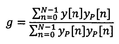
이는 0과 1 사이로 제한된다.This is limited to between 0 and 1.
마지막으로, 이득 g는 예를 들어 균일한 양자화를 이용하여 예를 들어 2 비트에서 양자화된다.Finally, the gain g is quantized, for example, in 2 bits using a uniform quantization, for example.
β는 필터의 세기를 제어하는데 사용된다. 1과 동일한 β는 전체 효과를 생성한다. 0과 동일한 β는 필터를 비활성화한다. 따라서, 본 발명의 실시예에서, 필터는 ß를 0의 값으로 설정함으로써 비활성화될 수 있다, 본 발명의 실시예에서, 필터가 활성화되면, ß는 0.5와 0.75 사이의 값으로 설정될 수 있다. 본 발명의 실시예에서, 필터가 활성화되면, ß는 0.625의 값으로 설정될 수 있다. B(z,Tfr)의 예는 위에 제공되어 있다. B(z,Tfr)의 순서 및 계수는 또한 비트레이트 및 출력 샘플링 레이트에 의존할 수 있다. 서로 다른 주파수 응답은 비트레이트 및 출력 샘플링 레이트의 각각의 조합을 위해 설계되고 튜닝될 수 있다.β is used to control the intensity of the filter. The same β as 1 produces the full effect. The same β as 0 disables the filter. Thus, in an embodiment of the invention, the filter can be deactivated by setting b to a value of zero. In an embodiment of the present invention, when the filter is activated, b can be set to a value between 0.5 and 0.75. In an embodiment of the present invention, when the filter is activated, b can be set to a value of 0.625. An example of B (z, T fr ) is provided above. The order and coefficients of B (z, T fr ) may also depend on the bit rate and the output sampling rate. Different frequency responses may be designed and tuned for each combination of bit rate and output sampling rate.
필터의 비활성화Disabling filters
필터는 하나 이상의 조화도(harmonicity) 측정치 및/또는 하나 이상의 시간적 구조 측정치의 조합에 기초하여 비활성화될 수 있다. 이러한 측정치의 예는 아래에서 설명된다:The filter may be deactivated based on a combination of one or more harmonicity measurements and / or one or more temporal structural measurements. Examples of such measurements are described below:
i) 정수 피치 지연에서의 정규화된 상관 관계와 같은 조화도 측정치는 단계 b에서 추정된다.i) Harmonization measure such as normalized correlation at constant pitch delay is estimated at step b.

정규화된 상관 관계는 입력 신호가 정수 피치 지연에 의해 완벽하게 예측 가능한 경우에는 1이고, 전혀 예측할 수 없는 경우에는 0이다. 그 후, (1에 가까운) 높은 값은 고조파 신호를 나타낸다. 더욱 강력한 결정을 위해, 과거 프레임의 정규화된 상관 관계는 또한 다음의 결정 시에 사용될 수 있다:The normalized correlation is 1 if the input signal is perfectly predictable by the integer pitch delay and 0 if it is unpredictable at all. Thereafter, a high value (close to 1) indicates a harmonic signal. For a more robust determination, the normalized correlation of the past frame can also be used in the following determination:
예를 들어 (norm.corr(curr.)*norm.corr.(prev.))>0.25인 경우, 필터는 비활성화되지 않는다.For example, if (norm.corr (curr.) * Norm.corr. (Prev.))> 0.25, the filter is not deactivated.
ⅱ) 예를 들어 에너지 샘플에 기초하여 계산되는 시간적 구조 측정치는 또한 과도 검출(예를 들어 시간적 평탄도 측정치, 에너지 변화)을 위한 과도 검출기에 의해 사용된다:Ii) For example, the temporal structural measurement calculated on the basis of the energy sample is also used by the transient detector for transient detection (for example, temporal flatness measurement, energy variation)
예를 들어 (시간적 평탄도 측정치 > 3.5 이상의 에너지 변화 > 3.5)이면, 필터는 비활성화된다.For example, if the temporal flatness measure> 3.5 energy change> 3.5, then the filter is deactivated.
하나 이상의 조화도 측정치의 결정에 관한 더 상세한 사항은 아래에서 설명된다.More details regarding the determination of one or more harmonic measurements are described below.
조화도의 측정치는 예를 들어 오디오 신호 또는 피치 지연에서나 주위에서의 이의 사전 수정된 버전의 정규화된 상관 관계에 의해 계산된다. 피치 지연은 심지어 제 1 스테이지 및 제 2 스테이지를 포함하는 스테이지에서 결정될 수 있으며, 제 1 스테이지 내에서, 피치 지연의 예비 추정은 제 1 샘플 레이트의 다운샘플링된 도메인에서 결정되고, 제 2 스테이지 내에서, 피치 지연의 예비 추정은 제 1 샘플 레이트보다 높은 제 2 샘플 레이트에서 세분할된다. 피치 지연은 예를 들어 자기 상관 관계를 이용하여 결정된다. 적어도 하나의 시간적 구조 측정치는 예를 들어 피치 정보에 따라 시간적으로 배치되는 시간적 영역 내에서 결정된다. 시간적 영역의 시간적 과거 헤드 엔드(past-heading end)는 예를 들어 피치 정보에 따라 배치된다. 시간적 영역의 시간적 과거 헤드 엔드는 시간적 영역의 시간적 과거 헤드 엔드가 피치 정보의 증가에 따라 단조롭게 증가하는 시간 량만큼 과거 방향으로 변위되도록 배치될 수 있다. 시간적 영역의 시간적 미래 헤드 엔드(future-heading end)는 시간적 영역 또는, 시간적 구조 측정치의 결정으로의 높은 영향의 영역의 시간적 과거 헤드 엔드로부터 현재 프레임의 시간적 미래 헤드 엔드로 연장하는 시간적 후보 영역 내에서 오디오 신호의 시간적 구조에 따라 위치될 수 있다. 시간적 후보 영역 내의 최대 에너지와 최소 에너지 샘플 사이의 진폭 또는 비율은 이것을 위해 사용될 수 있다. 예를 들면, 적어도 하나의 시간적 구조 측정치는 시간적 영역 내에서 오디오 신호의 평균 또는 최대 에너지 변화를 측정할 수 있고, 적어도 하나의 시간적 구조 측정치가 미리 정해진 제 1 임계값보다 작고, 조화도의 측정치가 현재 프레임 및/또는 이전의 프레임에 대해 제 2 임계값 위에 있을 경우에 비활성화의 조건은 충족될 수 있다. 조화도의 측정치가 현재 프레임에 대해 제 3 임계값 위에 있고, 조화도의 측정치가 현재 프레임 및/또는 이전의 프레임에 대해 피치 지연의 증가에 따라 감소하는 제 4 임계값 위에 있을 경우에 이러한 조건은 또한 충족된다.The measure of the degree of harmonization is calculated, for example, by the normalized correlation of the audio signal or a pre-modified version thereof at the pitch delay or around it. The pitch delay may even be determined in a stage comprising a first stage and a second stage wherein in a first stage a preliminary estimate of the pitch delay is determined in a downsampled domain of a first sample rate and in a second stage , The preliminary estimate of the pitch delay is subdivided at a second sample rate higher than the first sample rate. The pitch delay is determined using, for example, autocorrelation. The at least one temporal structural measurement is determined, for example, in a temporal region temporally arranged according to the pitch information. The temporal past-heading end of the temporal domain is arranged, for example, in accordance with the pitch information. The temporal past head end of the temporal region may be arranged such that the temporal past head end of the temporal region is displaced in the past direction by a time amount monotonically increasing with increasing pitch information. The temporal future head-end of the temporal domain is a temporal domain or a temporal domain within a temporal candidate region extending from the temporal past head end of the region of high impact to the determination of the temporal structure measurement to the temporal future head end of the current frame Can be positioned according to the temporal structure of the audio signal. The amplitude or ratio between the maximum energy and the minimum energy sample in the temporal candidate region can be used for this. For example, the at least one temporal structural measurement may measure an average or maximum energy change of the audio signal within the temporal region, and wherein the at least one temporal structural measurement is less than a predetermined first threshold, The condition of deactivation may be satisfied if it is above the second threshold for the current frame and / or previous frame. If the measure of the degree of coherence is above the third threshold for the current frame and the measure of the coherence is above a fourth threshold that decreases with increasing pitch delay for the current frame and / It is also satisfied.
측정치를 결정하기 위한 구체적인 실시예의 단계별 설명이 이제 제시된다.A step-by-step description of a specific embodiment for determining measurements is now presented.
단계 1. 과도 검출 및 시간적 측정치
입력 신호 SHP(n)는 시간 도메인 과도 검출기에 대한 입력이다. 입력 신호 SHP(n)는 고역 통과 필터링된다. 과도 검출의 HP 필터의 전달 함수는 다음에 의해 주어진다.The input signal S HP (n) is the input to the time domain transient detector. The input signal S HP (n) is high-pass filtered. The transfer function of the HP filter for transient detection is given by
HTD(z) = 0.375 - 0.5z-1 + 0.125z-2 (1)H TD (z) = 0.375 - 0.5z - 1 + 0.125z - 2 (1)
과도 검출의 HP 필터에 의해 필터링된 신호는 STD(n)로 표시된다. HP 필터링된 신호 STD(n)는 동일한 길이의 8개의 연속 세그먼트로 세그먼트된다. 각각의 세그먼트에 대한 HP 필터링된 신호 STD(n)의 에너지는 다음과 같이 계산된다:The signal filtered by the HP filter of transient detection is denoted by S TD (n). The HP filtered signal S TD (n) is segmented into eight consecutive segments of equal length. The energy of the HP filtered signal S TD (n) for each segment is calculated as:
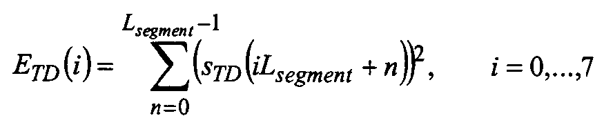
여기서, Lsegment = 
축적된 에너지를 다음 식을 이용하여 계산된다:The accumulated energy is calculated using the following equation:
EAcc = max(ETD(i-1),0.8125EAcc) (3)E Acc = max (E TD (i-1), 0.8125E Acc ) (3)
어택(attack)은 세그먼트 ETD(i)의 에너지가 일정 인수 attackRatio = 8.5만큼 축적된 에너지를 초과하고, attackIndex은 i로 설정될 경우에 검출된다:The attack is detected when the energy of the segment E TD (i) exceeds the energy accumulated by a certain factor attackRatio = 8.5 and the attackIndex is set to i:
ETD(i)> attackRatio·EAcc (4)E TD (i) > attackRatio E ACC (4)
위의 기준에 기초하여 어떤 어택도 검출되지 않지만, 강한 에너지 증가가 세그먼트 i에서 검출되면, attackIndex는 어택의 존재를 나타내지 않고 i로 설정된다. attackIndex는 기본적으로 어떤 추가적인 제한을 가진 프레임에서 마지막 어택의 위치로 설정된다.No attack is detected based on the above criteria, but if a strong energy increase is detected in segment i, attackIndex is set to i without indicating the presence of an attack. The attackIndex is basically set to the position of the last attack in the frame with some additional restrictions.
각각의 세그먼트에 대한 에너지 변화는 다음과 같이 계산된다:The energy change for each segment is calculated as:
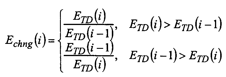
시간적 평탄도 측정치는 다음과 같이 계산된다:The temporal flatness measurement is calculated as follows:
최대 에너지 변화는 다음과 같이 계산된다:The maximum energy change is calculated as:
![]()
![]()
Echng(i) 또는 ETD(i)의 인덱스가 음이면, 그것은 현재 프레임에 대해 세그먼트 인덱싱한 이전의 세그먼트로부터의 값을 나타낸다.If the index of E chng (i) or E TD (i) is negative, it represents the value from the previous segment segment indexed for the current frame.
Npast는 과거 프레임으로부터의 세그먼트의 수이다. 그것은 시간적 평탄도 측정치가 ACELP/TCX 결정의 사용에 대해 계산되는 경우에 0과 동일하다. 시간적 평탄도 측정치가 TCX LTP 결정에 대해 계산될 경우, 그것은 다음과 동일하다:N past is the number of segments from the past frame. It is equal to 0 when the temporal flatness measure is calculated for use of ACELP / TCX crystals. When a temporal flatness measure is calculated for a TCX LTP determination, it is the same as:

Nnew는 현재 프레임으로부터의 세그먼트의 수이다. 그것은 비과도 프레임에 대해 8과 동일하다. 과도 프레임에 대해, 먼저 최대 및 최소의 에너지를 갖는 세그먼트의 위치가 발견된다:N new is the number of segments from the current frame. It is equal to 8 for non-transient frames. For a transient frame, first the position of a segment with maximum and minimum energy is found:
![]()
![]()
![]()
![]()
ETD(imin)>0.375ETD(imax)이면, Nnew는 imax-3로 설정되고, 그렇지 않으면, Nnew는 8로 설정된다.If E TD (i min ) > 0.375E TD (i max ) then N new is set to i max -3, otherwise N new is set to 8.
단계 2. 변환 블록 길이 스위칭
TCX의 오버랩 길이 및 변환 블록 길이는 과도 및 이의 위치의 존재에 의존한다.The overlap length and transform block length of the TCX depend on the presence of transient and its location.
표 1: 과도 위치에 기초한 오버랩 및 변환 길이의 코딩Table 1: Coding of overlap and transform lengths based on transient locations
윈도우와의 오버랩
The first frame of the next frame
Overlap with window
상술한 과도 검출기는 기본적으로 다수의 과도가 있는 경우 MINIMAL 오버랩은 FULL 오버랩보다 선호하는 HALF 오버랩보다 선호한다는 제한을 가진 마지막 어택의 인덱스를 반환한다. 2 또는 6에서의 어택이 충분히 강하지 않으면, MINIMAL 오버랩 대신에 HALF 오버랩이 선택된다.The transient detector described above basically returns the index of the last attack with the restriction that MINIMAL overlap is preferable to HALF overlap preferred over FULL overlap when there are multiple transitions. If the attack at 2 or 6 is not strong enough, a HALF overlap is selected instead of a MINIMAL overlap.
단계 3. 피치 추정Step 3. Pitch Estimation
프레임 당 하나의 피치 지연(정수 부분 + 소수 부분)은 복잡도를 감소시키고 추정 정확도를 향상시키기 위해 추정된다(3 단계 a) 내지 c)에서 상술한 바와 같은 프레임 크기, 예를 들어 20ms).One pitch delay per frame (integer part plus fractional part) is estimated to reduce complexity and improve estimation accuracy (frame sizes as described above in steps a) through c), e.g. 20 ms.
단계 4. 결정 비트
입력 오디오 신호가 임의의 고조파 콘텐츠를 포함하지 않거나 예측 기반 기술이 시간 구조의 왜곡(예를 들어 짧은 과도의 반복)을 도입하는 경우, 필터가 비활성화되는 결정이 취해진다.If the input audio signal does not contain any harmonic content or if the prediction-based technique introduces distortion of the time structure (e. G., Short transient repetition), a decision is taken that the filter is inactive.
결정은 정수 피치 지연 및 시간적 구조 측정치의 정규화된 상관 관계와 같은 다수의 파라미터에 기초하여 행해진다.The decision is made based on a number of parameters such as the integer pitch delay and the normalized correlation of the temporal structure measurement.
상술한 바와 같이 정수 피치 지연에서의 정규화된 상관 관계 norm_corr가 추정된다. 정규화된 상관 관계는 입력 신호가 정수 피치 지연에 의해 완벽하게 예측되는 경우에는 1이고, 전혀 예측할 수없는 경우에는 0이다. (1에 가까운) 높은 값은 고조파 신호를 나타낸다. 더욱 강력한 결정을 위해, 현재 프레임에 대한 정규화된 상관 관계(norm_corr(curr))와 비교하면, 과거 프레임의 정규화된 상관 관계(norm_corr(prev))는 또한 다음의 결정에서 이용될 수 있다. 예를 들면:The normalized correlation norm_corr at an integer pitch delay is estimated as described above. The normalized correlation is 1 if the input signal is perfectly predicted by the integer pitch delay and 0 if it is unpredictable at all. A high value (close to 1) indicates a harmonic signal. For a more robust determination, the normalized correlation (norm_corr (prev)) of the past frame can also be used in the next determination, as compared to the normalized correlation (norm_corr (curr)) for the current frame. For example:
(norm_corr(curr)*norm_corr(prev))> 0.25(norm_corr (curr) * norm_corr (prev)) > 0.25
또는or
max(norm_corr(curr),norm_corr(prev))> 0.5이면,max (norm_corr (curr), norm_corr (prev)) > 0.5,
현재 프레임은 몇몇 고조파 콘텐츠를 포함한다.The current frame contains some harmonic content.
시간적 구조 측정치는 강한 과도 또는 큰 시간 변화를 포함하는 신호에서 필터를 활성화하는 것을 방지하기 위해 과도 검출기(예를 들어 시간적 평탄도 측정치(식 (6)) 및 최대 에너지 변화 식(7))에 의해 계산될 수 있다. 시간적 특징은 현재 프레임(Nnew 세그먼트)와 피치 지연까지의 과거 프레임(Npast 세그먼트)을 포함하는 신호에서 계산된다. 천천히 감쇠하는 과도와 같은 단계의 경우, 특징의 모두 또는 일부는 LTP 필터링에 의해 도입된 스펙트럼의 비고조파 부분에서의 왜곡이 강한 오래 지속 과도(예를 들어 크래쉬 심벌(crash cymbal))의 마스킹에 의해 억제될 수 있기 때문에 과도(imax-3)의 위치까지만 계산된다. The time-resolved measurements are measured by a transient detector (e.g., temporal flatness measure (Eq. (6)) and a maximum energy change equation (7)) to prevent the filter from activating in a signal that includes a strong transient or a large transient Can be calculated. The temporal feature is computed in the signal comprising the current frame (N new segment) and the past frame up to the pitch delay (N past segment). In the case of stages such as slowly attenuating transients, all or part of the features may be distorted by non-harmonic portions of the spectrum introduced by LTP filtering by masking of strong long-term transients (e.g., crash cymbal) It is calculated only up to the position of the transient (i max -3) since it can be suppressed.
낮은 피치 신호에 대한 펄스 트레인은 과도 검출기에 의한 과도로서 검출될 수 있다. 따라서, 낮은 피치를 가진 신호에 대해, 과도 검출기로부터의 특징은 무시되고, 대신에 예를 들어 다음의 피치 지연에 의존하는 정규화된 상관 관계에 대한 추가적인 임계값이 있다:The pulse train for the low pitch signal can be detected as a transient by the transient detector. Thus, for a signal with a low pitch, the characteristics from the transient detector are ignored, and instead there is an additional threshold for a normalized correlation that depends, for example, on the following pitch delay:
norm_corr<= 1.2-Tint/L이면, 필터를 활성화하지 않는다.If norm_corr <= 1.2-T int / L, the filter is not activated.
일례의 결정이 아래에 보여지며, 여기서 b1은 약간의 비트레이트, 예를 들어 48 kbps이고, TCX_20은 프레임이 단일의 긴 블록을 이용하여 코딩되는 것을 나타내고, TCX_10은 프레임이 2,3,4 이상의 짧은 블록을 이용하여 코딩되는 것을 나타내며, TCX_20/TCX_10 결정은 상술한 과도 검출기의 출력에 기초한다. tempFlatness은 (6)에서 정의된 바와 같은 시간적 평탄도 측정치이고, maxEnergyChange는 (7)에서 정의된 바와 같은 최대 에너지 변화이다. 조건 norm_corr(curr)> 1.2-Tint/L은 또한 (1.2-norm_corr(curr))*L<Tint로서 기록될 수 있다.An example determination is shown below where b1 is a bit rate, e.g., 48 kbps, TCX_20 indicates that the frame is coded using a single long block, and TCX_10 indicates that the frame is 2, And the TCX_20 / TCX_10 decision is based on the output of the transient detector described above. tempFlatness is the temporal flatness measure as defined in (6), and maxEnergyChange is the maximum energy change as defined in (7). The condition norm_corr (curr)> 1.2-T int / L can also be written as (1.2-norm_corr (curr)) * L <T int .

그것은 장기 예측을 위한 결정 메커니즘이 사용되고, 신호의 어떤 부분이 결정에 이용되는 측정을 위해 사용되는 과도의 검출이 영향을 미치고, 장기 예측 필터의 비활성화를 직접 트리거하는 것이 아니라는 것을 위의 예로부터 명백해진다. It is clear from the above example that a decision mechanism for long term prediction is used and that the detection of the transient used for the measurement in which part of the signal is used for the determination is influential and does not directly trigger the inactivation of the long term prediction filter .
변환 길이 결정에 사용되는 시간적 측정치는 LTP 필터의 결정에 사용되는 시간적 측정치와 완전히 상이할 수 있거나, 오버랩하거나 정확하게 동일하지만 서로 다른 영역에서 계산될 수 있다. 낮은 피치 신호에 대해, 피치 지연에 의존하는 정규화된 상관 관계에 대한 임계값이 도달될 경우에 과도의 검출은 완전히 무시될 수 있다.The temporal measure used to determine the transform length may be completely different from the temporal measure used to determine the LTP filter, or overlap or exactly the same, but may be calculated in different regions. For a low pitch signal, the detection of the transient can be completely ignored if a threshold for a normalized correlation that depends on the pitch delay is reached.
가능한 불연속성을 제거하기 위한 기술Techniques to eliminate possible discontinuities
한 프레임씩 선형 필터 H(z)를 적용함으로써 발생되는 불연속성을 제거하기 위한 가능한 기술이 이제 설명된다. 선형 필터는 설명된 LTP 필터일 수 있다. 선형 필터는 FIR(유한 임펄스 응답) 필터 또는 IIR(무한 임펄스 응답) 필터일 수 있다. 제안된 접근 방식은 과거 프레임의 필터 파라미터로 현재 프레임의 부분을 필터링하지 않으며, 따라서 알려진 접근 방식의 가능한 문제를 방지한다. 제안된 접근 방식은 불연속성을 제거하기 위해 LPC 필터를 사용한다. 이러한 LPC 필터는 (선형 시불변 필터 H(z)에 의해 필터링되거나 필터링되지 않는) 오디오 신호에서 추정되며, 따라서 (H(z)에 의해 필터링되거나 필터링되지 않는) 오디오 신호의 스펙트럼 형상의 양호한 모델이다. 그 후, 오디오 신호의 스펙트럼 형상이 불연속성을 마스크하도록 LPC 필터가 이용된다.A possible technique for eliminating the discontinuities generated by applying the linear filter H (z) one frame at a time is now described. The linear filter may be the LTP filter described. The linear filter may be an FIR (finite impulse response) filter or an IIR (infinite impulse response) filter. The proposed approach does not filter parts of the current frame with filter parameters of past frames, thus avoiding possible problems with known approaches. The proposed approach uses an LPC filter to remove discontinuities. This LPC filter is a good model of the spectral shape of the audio signal (which is filtered or not filtered by H (z) . Thereafter, an LPC filter is used so that the spectral shape of the audio signal masks the discontinuity.
LPC 필터는 다양한 방식으로 추정될 수 있다. 그것은 예를 들어 오디오 신호(현재 및/또는 과거 프레임)과 Levinson-Durbin 알고리즘을 이용하여 추정될 수 있다. 그것은 또한 Levinson-Durbin 알고리즘을 이용하여 과거 필터링된 프레임 신호에서 계산될 수 있다.The LPC filter can be estimated in various ways. It can be estimated, for example, using an audio signal (current and / or past frame) and the Levinson-Durbin algorithm. It can also be computed from past filtered frame signals using the Levinson-Durbin algorithm.
H(z)가 오디오 코덱에 사용되고, 오디오 코덱이 이미 예를 들어 변환 기반의 오디오 코덱에서 양자화 잡음을 형성하기 위해 (양자화되거나 양자화되지 않은) LPC 필터를 사용하면, 이러한 LPC 필터는 새로운 LPC 필터를 추정하는데 필요한 추가적인 복잡도없이 불연속성을 평활화하는데 직접 사용될 수 있다.If H (z) is used in an audio codec and the audio codec already uses an LPC filter (quantized or unquantized) to form quantization noise, for example, in a transform-based audio codec, It can be used directly to smooth discontinuities without the additional complexity needed to estimate.
FIR 필터 케이스 및 IIR 필터 케이스에 대한 현재 프레임의 처리에 대해서는 아래에서 설명된다. 과거 프레임은 이미 처리되는 것으로 추정된다.The processing of the current frame for the FIR filter case and the IIR filter case is described below. It is assumed that the past frame has already been processed.
FIR 필터 케이스:FIR filter case:
1. 현재 프레임을 현재 프레임의 필터 파라미터로 필터링하고, 필터링된 현재 프레임을 생성한다.1. Filter the current frame with the filter parameters of the current frame, and generate a filtered current frame.
2. 순서 M으로 (양자화되거나 양자화되지 않은) LPC 필터를 고려하고. (필터링되거나 필터링되지 않은) 오디오 신호 상에서 추정된다.2. Consider an LPC filter (quantized or unquantized) in order M. (Filtered or unfiltered) audio signal.
3. 과거 프레임의 M 마지막 샘플은 필터 H(z) 및 현재 프레임의 계수로 필터링되고, 필터링된 신호의 제 1 부분을 생성한다.3. The M last sample of the previous frame is filtered with the filter H (z) and the coefficients of the current frame, and generates the first part of the filtered signal.
4. 그리고 나서, 필터링된 과거 프레임의 M 마지막 샘플은 필터링된 신호의 제 1 부분으로부터 감산되고, 필터링된 신호의 제 2 부분을 생성한다.4. The M last sample of the filtered past frame is then subtracted from the first portion of the filtered signal and generates a second portion of the filtered signal.
5. 그리고 나서, LPC 필터의 제로 임펄스 응답(ZIR)은 LPC 필터 및 필터링된 신호의 제 2 부분과 동일한 초기 상태로 제로 샘플의 프레임을 필터링함으로써 생성된다.5. The zero impulse response (ZIR) of the LPC filter is then generated by filtering the frame of zero samples in the same initial state as the LPC filter and the second portion of the filtered signal.
6. ZIR은 선택적으로 진폭이 0으로 빠르게 진행하도록 윈도잉될 수 있다.6. The ZIR can optionally be windowed to advance the amplitude to zero.
7. ZIR의 시작 부분은 필터링된 현재 프레임의 대응하는 시작 부분으로부터 감산된다.7. The beginning of the ZIR is subtracted from the corresponding beginning of the filtered current frame.
IIR 필터 케이스:IIR filter case:
1. 순서 M으로 (양자화되거나 양자화되지 않은) LPC 필터를 고려하고. (필터링되거나 필터링되지 않은) 오디오 신호 상에서 추정된다.1. Consider an LPC filter (quantized or unquantized) in order M. (Filtered or unfiltered) audio signal.
2. 과거 프레임의 M 마지막 샘플은 필터 H(z) 및 현재 프레임의 계수로 필터링되고, 필터링된 신호의 제 1 부분을 생성한다.2. The M last sample of the previous frame is filtered with the filter H (z) and the coefficients of the current frame and generates the first part of the filtered signal.
3. 그리고 나서, 필터링된 과거 프레임의 M 마지막 샘플은 필터링된 신호의 제 1 부분으로부터 감산되고, 필터링된 신호의 제 2 부분을 생성한다.3. The M last sample of the filtered past frame is then subtracted from the first portion of the filtered signal and generates a second portion of the filtered signal.
4. 그리고 나서, LPC 필터의 제로 임펄스 응답(ZIR)은 LPC 필터 및 필터링된 신호의 제 2 부분과 동일한 초기 상태로 제로 샘플의 프레임을 필터링함으로써 생성된다.4. The Zero Impulse Response (ZIR) of the LPC filter is then generated by filtering the frame of zero samples to the same initial state as the LPC filter and the second portion of the filtered signal.
5. ZIR은 선택적으로 진폭이 0으로 빠르게 진행하도록 윈도잉될 수 있다.5. The ZIR may optionally be windowed such that the amplitude rapidly advances to zero.
6. 그리고 나서, 현재 프레임의 시작 부분은 현재 프레임의 제 1 샘플로 시작하는 샘플마다 처리된다.6. The beginning of the current frame is then processed for each sample starting with the first sample of the current frame.
7. 샘플은 필터 H(z) 및 현재 프레임 파라미터로 필터링되고, 제 1 필터링된 샘플을 생성한다.7. The sample is filtered with the filter H (z) and the current frame parameter, and generates a first filtered sample.
8. 그리고 나서, ZIR의 대응하는 샘플은 제 1 필터링된 샘플로부터 감산되고, 필터링된 현재 프레임의 대응하는 샘플을 생성한다. 8. The corresponding sample of the ZIR is then subtracted from the first filtered sample and generates a corresponding sample of the filtered current frame.
9. 다음 샘플로 이동한다.9. Go to the next sample.
10. 현재 프레임의 시작 부분의 마지막 샘플이 처리될 때까지 9 내지 12를 반복한다. 10. Repeat 9 through 12 until the last sample at the beginning of the current frame is processed.
11. 현재 프레임의 필터 파라미터로 현재 프레임의 나머지 샘플을 필터링한다.11. Filter the remaining samples of the current frame with the filter parameters of the current frame.
따라서, 본 발명의 실시예는 간단하고 정확한 방식으로 세그먼트 SNR의 추정과 적절한 인코딩 알고리즘의 선택을 허용한다. 특히, 본 발명의 실시예는 적절한 코딩 알고리즘의 개방 루프 선택을 허용하며, 고조파를 갖는 오디오 신호의 경우에 코딩 알고리즘의 부적절한 선택은 회피된다.Thus, embodiments of the present invention allow estimation of the segment SNR and selection of an appropriate encoding algorithm in a simple and accurate manner. In particular, embodiments of the present invention allow open loop selection of a suitable coding algorithm, and in the case of an audio signal with harmonics, improper selection of the coding algorithm is avoided.
위의 실시예에서, 세그먼트 SNR은 각각의 서브프레임에 대해 추정된 SNR의 평균을 계산함으로써 추정된다. 대안적 실시예에서, 전체 프레임의 SNR은 프레임을 서브프레임으로 분할하지 않고 추정될 수 있다.In the above embodiment, the segment SNR is estimated by calculating an average of the estimated SNRs for each subframe. In an alternative embodiment, the SNR of the entire frame may be estimated without dividing the frame into subframes.
본 발명의 실시예는 폐루프 선택에 필요한 다수의 단계가 생략되므로 폐루프 선택에 비해 계산 시간의 상당한 감소를 허용한다.Embodiments of the present invention allow a significant reduction in computation time over closed loop selection since a number of steps required for closed loop selection are omitted.
따라서, 다수의 단계 및 이와 관련된 계산 시간은 여전히 양호한 성능을 가진 적절한 인코딩 알고리즘의 선택을 허용하면서 본 발명의 접근 방식에 의해 절약될 수 있다.Thus, the number of steps and the computation time associated therewith can still be saved by the approach of the present invention, allowing for the selection of an appropriate encoding algorithm with good performance.
일부 양태가 장치의 맥락에서 설명되었지만, 이러한 양태는 또한 대응하는 방법의 설명을 나타내는 것이 명백하여, 여기서 블록 또는 장치는 방법 단계 또는 방법 단계의 특징에 대응한다. 유사하게, 방법 단계의 맥락에서 설명된 양태는 또한 대응하는 블록 또는 항목의 설명 또는 대응하는 장치의 특징을 나타낸다. While some aspects have been described in the context of a device, it is also evident that such aspects also represent a description of a corresponding method, wherein the block or device corresponds to a feature of a method step or method step. Similarly, aspects described in the context of a method step also represent a description of a corresponding block or item or a feature of a corresponding device.
본 명세서에서 설명된 장치의 실시예 및 이의 특징은 컴퓨터, 하나 이상의 프로세서, 하나 이상의 마이크로프로세서, 필드 프로그램 가능한 게이트 어레이(FPGA), 주문형 집적 회로(ASIC) 등 또는 이들의 조합에 의해 구현될 수 있으며, 이들은 설명된 기능을 제공하기 위해 구성되거나 프로그래밍된다.Embodiments of the apparatus and the features described herein may be implemented by a computer, one or more processors, one or more microprocessors, a field programmable gate array (FPGA), an application specific integrated circuit (ASIC) , They are configured or programmed to provide the described functionality.
방법 단계의 일부 또는 모두는 예를 들어 마이크로프로세서, 프로그램 가능한 컴퓨터 또는 전자 회로와 같은 하드웨어 장치에 의해(또는 이용하여) 실행될 수 있다. 일부 실시예에서, 가장 중요한 방법 단계 중일부의 하나 이상은 이러한 장치에 의해 실행될 수 있다.Some or all of the method steps may be performed by (or using) a hardware device such as, for example, a microprocessor, a programmable computer or an electronic circuit. In some embodiments, one or more of the most important method steps may be performed by such an apparatus.
어떤 구현 요구 사항에 따라, 본 발명의 실시예는 하드웨어 또는 소프트웨어로 구현될 수 있다. 이러한 구현은 디지털 저장 매체와 같은 비일시적 저장 매체, 예를 들어 플로피 디스크, DVD, Blu-Ray, CD, ROM, PROM, EPROM, EEPROM 또는 FLASH 메모리를 이용하여 수행될 수 있으며, 이러한 매체는 각각의 방법이 수행되도록 프로그램 가능한 컴퓨터 시스템과 협력하는(또는 협력할 수 있는) 전자적으로 판독 가능한 제어 신호를 저장한다. 그래서, 디지털 저장 매체는 컴퓨터 판독 가능할 수 있다.According to certain implementation requirements, embodiments of the present invention may be implemented in hardware or software. Such implementations may be performed using non-volatile storage media such as digital storage media, such as floppy disks, DVD, Blu-Ray, CD, ROM, PROM, EPROM, EEPROM or FLASH memory, Readable < / RTI > control signals that cooperate (or cooperate) with the programmable computer system to perform the method. Thus, the digital storage medium may be computer readable.
본 발명에 따른 일부 실시예는 본 명세서에서 설명된 방법 중 하나가 수행되도록 프로그램 가능한 컴퓨터 시스템과 협력할 수 있는 전자적으로 판독 가능한 제어 신호를 갖는 데이터 캐리어를 포함한다. Some embodiments in accordance with the present invention include a data carrier having an electronically readable control signal that can cooperate with a programmable computer system to perform one of the methods described herein.
일반적으로, 본 발명의 실시예는 프로그램 코드를 가진 컴퓨터 프로그램 제품으로 구현될 수 있으며, 프로그램 코드는 컴퓨터 프로그램 제품이 컴퓨터 상에서 실행될 때 방법 중 하나를 수행하기 위해 동작한다. 프로그램 코드는 예를 들어 기계 판독 가능한 캐리어 상에 저장될 수 있다. In general, embodiments of the invention may be implemented as a computer program product with program code, the program code being operative to perform one of the methods when the computer program product is run on a computer. The program code may be stored, for example, on a machine readable carrier.
다른 실시예는 본 명세서에서 설명되고, 기계 판독 가능 캐리어 상에 저장된 방법 중 하나를 수행하기 위한 컴퓨터 프로그램을 포함한다. Other embodiments include a computer program for performing one of the methods described herein and stored on a machine-readable carrier.
그래서, 다시 말하면, 본 발명의 방법의 실시예는 컴퓨터 프로그램이 컴퓨터 상에서 실행될 때 본 명세서에 설명된 방법 중 하나를 수행하기 위해 프로그램 코드를 갖는 컴퓨터 프로그램이다. Thus, in other words, an embodiment of the method of the present invention is a computer program having program code for performing one of the methods described herein when the computer program is run on a computer.
그래서, 본 발명의 방법의 추가의 실시예는 데이터 캐리어(또는 디지털 저장 매체, 또는 컴퓨터 판독 가능한 매체)이며, 이러한 데이터 캐리어는 본 명세서에서 설명된 방법 중 하나를 수행하기 위한 컴퓨터 프로그램을 기록하고 포함한다. 데이터 캐리어, 디지털 저장 매체 또는 기록된 매체는 전형적으로 유형(tangible) 및/또는 비일시적이다.Thus, a further embodiment of the method of the present invention is a data carrier (or digital storage medium, or computer readable medium) that records and includes a computer program for performing one of the methods described herein do. Data carriers, digital storage media or recorded media are typically tangible and / or non-volatile.
그래서, 본 발명의 방법의 추가의 실시예는 본 명세서에서 설명된 방법 중 하나를 수행하기 위한 컴퓨터 프로그램을 나타내는 데이터 스트림 또는 신호의 시퀀스이다. 데이터 스트림 또는 신호의 시퀀스는 예를 들어 데이터 통신 접속, 예를 들어 인터넷을 통해 전송되도록 구성될 수 있다. Thus, a further embodiment of the method of the present invention is a sequence of data streams or signals representing a computer program for performing one of the methods described herein. The data stream or sequence of signals may be configured to be transmitted, for example, over a data communication connection, e.g., over the Internet.
추가의 실시예는 본 명세서에서 설명된 방법 중 하나를 수행하도록 구성되거나 적응되는 처리 수단, 예를 들어 컴퓨터 또는 프로그램 가능한 논리 장치를 포함한다. Additional embodiments include processing means, e.g., a computer or programmable logic device, configured or adapted to perform one of the methods described herein.
추가의 실시예는 본 명세서에서 설명된 방법 중 하나를 수행하기 위한 컴퓨터 프로그램을 설치한 컴퓨터를 포함한다. Additional embodiments include a computer having a computer program installed thereon for performing one of the methods described herein.
본 발명에 따른 추가의 실시예는 본 명세서에서 설명된 방법 중 하나를 수행하기 위한 컴퓨터 프로그램을 수신기로(예를 들어, 전자적 또는 광학적으로) 전송하도록 구성되는 장치 또는 시스템을 포함한다. 수신기는 예를 들어 컴퓨터, 모바일 장치, 메모리 장치 등일 수 있다. 장치 또는 시스템은 예를 들어 컴퓨터 프로그램을 수신기로 전송하기 위한 파일 서버를 포함할 수 있다.Additional embodiments in accordance with the present invention include an apparatus or system configured to transmit (e.g., electronically or optically) a computer program to a receiver for performing one of the methods described herein. The receiver may be, for example, a computer, a mobile device, a memory device, or the like. A device or system may include, for example, a file server for transmitting a computer program to a receiver.
일부 실시예에서, 프로그램 가능한 논리 장치(예를 들어, 필드 프로그램 가능한 게이트 어레이)는 본 명세서에서 설명된 방법의 기능의 일부 또는 모두를 수행하기 위해 이용될 수 있다. 일부 실시예에서, 필드 프로그램 가능한 게이트 어레이는 본 명세서에서 설명된 방법 중 하나를 수행하기 위해 마이크로 프로세서와 협력할 수 있다. 일반적으로, 이러한 방법은 바람직하게는 임의의 하드웨어 장치에 의해 수행된다. In some embodiments, a programmable logic device (e.g., a field programmable gate array) may be utilized to perform some or all of the functions of the method described herein. In some embodiments, the field programmable gate array may cooperate with the microprocessor to perform one of the methods described herein. Generally, this method is preferably performed by any hardware device.
상술한 실시예는 단지 본 발명의 원리에 대한 예시이다. 본 명세서에서 설명된 배치의 수정 및 변형과 상세 사항은 당업자에게는 자명할 것으로 이해된다. 따라서, 본 명세서에서 실시예의 설명에 의해 제시된 특정 상세 사항에 의해서가 아니라 첨부된 청구 범위에 의해서만 제한되는 것으로 의도된다.The above-described embodiments are merely illustrative of the principles of the present invention. Modifications and variations of the arrangements and details described herein will be apparent to those skilled in the art. Accordingly, it is intended that the invention not be limited by the specific details presented herein, but only by the appended claims.
Claims (15)
상기 오디오 신호를 수신하고, 상기 오디오 신호의 고조파의 진폭을 감소시키며, 상기 오디오 신호의 필터링된 버전을 출력하도록 구성된 장기 예측 필터;
상기 오디오 신호의 부분에 대한 제 1 품질 측정치로 상기 오디오 신호의 부분의 SNR(신호 대 잡음비) 또는 세그먼트 SNR을 추정할 시에 상기 오디오 신호의 필터링된 버전을 사용하기 위한 제 1 추정기(12)로서, 상기 제 1 품질 측정치는 상기 제 1 인코딩 알고리즘과 관련되고, 상기 제 1 품질 측정치를 추정하는 것은 상기 제 1 인코딩 알고리즘의 왜곡 추정치를 획득하고, 상기 제 1 인코딩 알고리즘을 사용하여 상기 오디오 신호의 부분을 실제로 인코딩 및 디코딩하지 않고 상기 오디오 신호의 부분 및 상기 제 1 인코딩 알고리즘의 왜곡 추정치에 기초하여 상기 제 1 품질 측정치를 추정하기 위해 상기 제 1 인코딩 알고리즘의 근사화를 수행하는 것을 포함하는 상기 제 1 추정기(12);
상기 오디오 신호의 부분에 대한 제 2 품질 측정치로 SNR 또는 세그먼트 SNR을 추정하기 위한 제 2 추정기(14)로서, 상기 제 2 품질 측정치는 상기 제 2 인코딩 알고리즘과 관련되고, 상기 제 2 품질 측정치를 추정하는 것은 상기 제 2 인코딩 알고리즘의 왜곡 추정치를 획득하고, 상기 제 2 인코딩 알고리즘을 사용하여 상기 오디오 신호의 부분을 실제로 인코딩 및 디코딩하지 않고 상기 오디오 신호의 부분 및 상기 제 2 인코딩 알고리즘의 왜곡 추정치를 이용하여 상기 제 2 품질 측정치를 추정하기 위해 상기 제 2 인코딩 알고리즘의 근사화를 수행하는 것을 포함하는 상기 제 2 추정기(14); 및
상기 제 1 품질 측정치와 상기 제 2 품질 측정치 사이의 비교에 기초하여 상기 제 1 인코딩 알고리즘 또는 상기 제 2 인코딩 알고리즘을 선택하기 위한 제어기(16)를 포함하며,
상기 제 1 인코딩 알고리즘은 변환 코딩 알고리즘, MDCT(수정된 이산 코사인 변환) 기반의 코딩 알고리즘 또는 TCX(변환 코딩 여기) 코딩 알고리즘이고, 상기 제 2 인코딩 알고리즘은 CELP(코드 여기 선형 예측) 코딩 알고리즘 또는 ACELP(대수 코드 여기 선형 예측) 코딩 알고리즘인 장치.Selecting one of a first encoding algorithm having a first characteristic and a second encoding algorithm having a second characteristic to encode a portion of the audio signal (40) to obtain an encoded version of the portion of the audio signal (40) (10), comprising:
A long term prediction filter configured to receive the audio signal, reduce the amplitude of harmonics of the audio signal, and output a filtered version of the audio signal;
As a first estimator (12) for using a filtered version of the audio signal in estimating a SNR (signal-to-noise ratio) or a segment SNR of a portion of the audio signal with a first quality measure for the portion of the audio signal Wherein the first quality measure is associated with the first encoding algorithm; estimating the first quality measure comprises obtaining a distortion estimate of the first encoding algorithm; and using the first encoding algorithm, And performing an approximation of the first encoding algorithm to estimate the first quality measure based on a distortion estimate of the first encoding algorithm and a portion of the audio signal without actually encoding and decoding the first estimate, (12);
A second estimator (14) for estimating an SNR or segment SNR with a second quality measure for a portion of the audio signal, the second quality measure being associated with the second encoding algorithm, the second quality measure being estimated Of the second encoding algorithm is used to obtain a distortion estimate of the second encoding algorithm and to use the distortion estimate of the second encoding algorithm and the portion of the audio signal without actually encoding and decoding the portion of the audio signal using the second encoding algorithm The second estimator (14) comprising performing an approximation of the second encoding algorithm to estimate the second quality measure; And
And a controller (16) for selecting the first encoding algorithm or the second encoding algorithm based on a comparison between the first quality measure and the second quality measure,
Wherein the first encoding algorithm is a transform coding algorithm, a MDCT (Modified Discrete Cosine Transform) based coding algorithm or a TCX (Transform Coding Excitation) coding algorithm and the second encoding algorithm is a CELP (Code Excited Linear Prediction) (Algebraic Code Excitation Linear Prediction) coding algorithm.
상기 장기 예측 필터의 전달 함수는 피치 지연의 정수 부분과 상기 피치 지연의 소수 부분에 따른 다중 탭 필터를 포함하는 장치. The method according to claim 1,
Wherein the transfer function of the long term prediction filter comprises a multi-tap filter according to an integer part of the pitch delay and a fractional part of the pitch delay.
상기 장기 예측 필터는 다음과 같은 전달 함수를 가지며:
P(z) = 1 - βgB(z, Tfr)z-Tint
Tint 및 Tfr은 피치 지연의 정수 및 소수 부분이고, g는 이득이고, β는 상기 장기 예측 필터의 강도를 제어하는 가중치이며, B(z, Tfr)는 계수가 상기 피치 지연의 소수 부분에 의존하는 FIR 저역 통과 필터인 장치. The method according to claim 1,
Wherein the long term prediction filter has the following transfer function:
P (z) = 1 -? GB (z, T fr ) z -Tint
T int and T fr are integers and fractional parts of the pitch delay, g is the gain, beta is the weight controlling the strength of the long term prediction filter, and B (z, T fr ) / RTI > is a FIR low-pass filter that is dependent on the input signal.
하나 이상의 조화도 측정치 및/또는 하나 이상의 시간적 구조 측정치의 조합에 기초하여 상기 필터를 비활성화하기 위한 비활성화 유닛을 더 포함하는 장치.The method according to claim 1,
Further comprising an inactivation unit for deactivating the filter based on a combination of one or more degree of harmonization measurements and / or one or more temporal structure measurements.
상기 하나 이상의 조화도 측정치는 정규화된 상관 관계 또는 예측 이득 중 적어도 하나를 포함하고, 상기 하나 이상의 시간적 구조 측정치는 시간적 평탄도 측정치 또는 에너지 변화 중 적어도 하나를 포함하는 장치.5. The method of claim 4,
Wherein the one or more degrees of coherence measurements comprise at least one of a normalized correlation or a predicted gain and wherein the one or more temporal structure measurements comprise at least one of a temporal flatness measure or an energy change.
상기 필터는 프레임 단위로 상기 오디오 신호에 적용되고, 상기 장치는 상기 필터에 의해 생성된 상기 오디오 신호의 불연속성을 제거하기 위한 유닛을 더 포함하는 장치.The method according to claim 1,
Wherein the filter is applied to the audio signal on a frame-by-frame basis, the apparatus further comprising: a unit for eliminating the discontinuity of the audio signal produced by the filter.
상기 제 1 및 제 2 추정기는 상기 오디오 신호의 가중된 버전의 부분의 SNR 또는 세그먼트 SNR을 추정하도록 구성되는 장치.The method according to claim 1,
Wherein the first and second estimators are configured to estimate an SNR or a segment SNR of a portion of a weighted version of the audio signal.
상기 제 1 추정기(12)는 상기 오디오 신호의 부분을 양자화할 때 상기 제 1 인코딩 알고리즘에 사용되는 양자화기가 도입하는 추정된 양자화 왜곡은 결정하고, 상기 오디오 신호의 가중된 버전의 부분의 에너지와 상기 추정된 양자화 왜곡에 기초하여 상기 제 1 품질 측정치를 추정하도록 구성되고, 상기 제 1 추정기(12)는 상기 오디오 신호의 부분이 상기 제 1 인코딩 알고리즘에 사용된 엔트로피 인코더 및 양자화기로 인코딩될 때 주어진 타겟 비트레이트를 생성하도록 상기 오디오 신호의 부분에 대한 글로벌 이득은 추정하도록 구성되며, 상기 제 1 추정기(12)는 상기 추정된 글로벌 이득에 기초하여 상기 추정된 양자화 왜곡을 결정하도록 더 구성되는 장치. The method according to claim 1,
Wherein the first estimator (12) determines an estimated quantization distortion introduced by a quantizer used in the first encoding algorithm when quantizing the portion of the audio signal, and wherein the energy of the portion of the weighted version of the audio signal Wherein the first estimator (12) is configured to estimate the first quality measure based on the estimated quantization distortion, wherein the first estimator (12) is configured to estimate the first quantization distortion based on the quantization distortion of a given target when the portion of the audio signal is encoded into an entropy encoder and a quantizer used in the first encoding algorithm Wherein the global estimator is configured to estimate a global gain for a portion of the audio signal to produce a bit rate, and wherein the first estimator (12) is further configured to determine the estimated quantization distortion based on the estimated global gain.
상기 제 2 추정기(14)는 상기 오디오 신호의 부분을 인코딩하기 위해 적응 코드북을 사용할 때 상기 제 2 인코딩 알고리즘에 사용된 상기 적응 코드북이 도입하는 추정된 적응 코드북 왜곡을 결정하도록 구성되고, 상기 제 2 추정기(14)는 상기 오디오 신호의 가중된 버전의 부분의 에너지 및 상기 추정된 적응 코드북 왜곡에 기초하여 상기 제 2 품질 측정치를 추정하도록 구성되고, 상기 오디오 신호의 부분의 복수의 서브 부분의 각각에 대해, 상기 제 2 추정기(14)는 전처리 스테이지에서 결정된 피치 지연에 의해 과거로 시프트되는 가중된 오디오 신호의 서브 부분의 버전에 기초하여 상기 적응 코드북을 근사화하고, 상기 가중된 오디오 신호의 부분의 서브 부분과 근사화된 적응 코드북 사이의 에러가 최소화되도록 적응 코드북 이득을 추정하며, 상기 가중된 오디오 신호의 부분의 서브 부분과 적응 코드북 이득에 의해 스케일링된 근사화된 적응 코드북 사이의 에러의 에너지에 기초하여 추정된 적응 코드북 왜곡을 결정하도록 구성되는 장치.The method according to claim 1,
Wherein the second estimator (14) is configured to determine an estimated adaptive codebook distortion introduced by the adaptive codebook used in the second encoding algorithm when using an adaptive codebook to encode a portion of the audio signal, The estimator 14 is configured to estimate the second quality measure based on the energy of the portion of the weighted version of the audio signal and the estimated adaptive codebook distortion and wherein each of the plurality of sub- The second estimator 14 approximates the adaptive codebook based on the version of the sub-portion of the weighted audio signal shifted in the past by the determined pitch delay in the preprocessing stage, Estimates an adaptive codebook gain such that errors between the portion and the approximated adaptive codebook are minimized, And to determine an estimated adaptive codebook distortion based on the energy of the error between the sub-portion of the portion of the intermediate audio signal and the approximated adaptive codebook scaled by the adaptive codebook gain.
상기 제 2 추정기(14)는 상기 오디오 신호의 부분의 각각의 서브 부분에 대해 결정되는 상기 추정된 적응 코드북 왜곡을 일정한 인수만큼 감소시키도록 더 구성되는 장치. 10. The method of claim 9,
Wherein the second estimator (14) is further configured to reduce the estimated adaptive codebook distortion determined for each sub-portion of the portion of the audio signal by a constant factor.
상기 제 2 추정기(14)는 상기 제 2 인코딩 알고리즘에 사용되는 적응 코드북이 상기 오디오 신호의 부분을 인코딩하기 위해 상기 적응 코드북을 이용할 때에 도입하는 추정된 적응 코드북 왜곡은 결정하도록 구성되고, 상기 제 2 추정기(14)는 상기 오디오 신호의 가중된 버전의 부분의 에너지 및 상기 추정된 적응 코드북 왜곡에 기초하여 상기 제 2 품질 측정치를 추정하도록 구성되고, 상기 제 2 추정기(14)는 전처리 스테이지에서 결정된 피치 지연에 의해 과거로 시프트되는 가중된 오디오 신호의 부분의 버전에 기초하여 상기 적응 코드북을 근사화하고, 상기 가중된 오디오 신호의 부분과 근사화된 적응 코드북 사이의 에러가 최소화되도록 적응 코드북 이득을 추정하며, 상기 가중된 오디오 신호의 부분과 적응 코드북 이득에 의해 스케일링된 근사화된 적응 코드북 사이의 에러의 에너지에 기초하여 추정된 적응 코드북 왜곡을 결정하도록 구성되는 장치.The method according to claim 1,
Wherein the second estimator (14) is configured to determine an estimated adaptive codebook distortion introduced by an adaptive codebook used in the second encoding algorithm when utilizing the adaptive codebook to encode a portion of the audio signal, The estimator (14) is configured to estimate the second quality measure based on the energy of the portion of the weighted version of the audio signal and the estimated adaptive codebook distortion, and the second estimator (14) Approximating the adaptive codebook based on a version of the portion of the weighted audio signal that is shifted past by delay and estimating an adaptive codebook gain such that errors between the portion of the weighted audio signal and the approximated adaptive codebook are minimized, The weighted audio signal is weighted by an adaptive codebook gain, And determine an estimated adaptive codebook distortion based on the energy of the error between the adaptive codebook.
제 1 항 내지 제 11 항 중 어느 한 항에 따른 장치(10), 상기 제 1 인코딩 알고리즘을 수행하기 위한 제 1 인코더 스테이지(26) 및 제 2 인코딩 알고리즘을 수행하기 위한 제 2 인코더 스테이지(28)를 포함하며,
상기 인코딩 장치(20)는 상기 제어기(16)에 의한 선택에 따라 상기 제 1 인코딩 알고리즘 또는 상기 제 2 인코딩 알고리즘을 이용하여 상기 오디오 신호의 부분을 인코딩하도록 구성되는 인코딩 장치.An apparatus (20) for encoding a portion of an audio signal,
12. A device (10) according to any one of the preceding claims, a first encoder stage (26) for performing said first encoding algorithm and a second encoder stage (28) for performing a second encoding algorithm, / RTI >
Wherein the encoding device (20) is configured to encode a portion of the audio signal using the first encoding algorithm or the second encoding algorithm in accordance with the selection by the controller (16).
제 12 항에 따른 인코딩 장치(20)로서 오디오 신호의 부분의 인코딩된 버전을 출력하는 인코딩 장치(20); 및
상기 오디오 신호의 부분의 인코딩된 버전 및 상기 오디오 신호의 부분을 인코딩하는데 사용되는 알고리즘의 지시를 수신하고, 지시된 알고리즘을 이용하여 상기 오디오 신호의 부분의 인코딩된 버전을 디코딩하는 디코더;를 포함하는 인코딩 및 디코딩 시스템.An encoding and decoding system,
An encoding device (20) according to claim 12 for encoding an encoded version of a portion of an audio signal (20); And
And a decoder to receive an encoded version of the portion of the audio signal and an indication of an algorithm used to encode the portion of the audio signal and to decode an encoded version of the portion of the audio signal using the indicated algorithm Encoding and decoding system.
상기 오디오 신호의 고조파의 진폭을 감소시키고, 상기 오디오 신호의 필터링된 버전을 출력하기 위해 장기 예측 필터를 이용하여 상기 오디오 신호를 필터링하는 단계;
상기 오디오 신호의 부분에 대한 제 1 품질 측정치로 상기 오디오 신호의 부분의 SNR 또는 세그먼트 SNR을 추정할 시에 상기 오디오 신호의 필터링된 버전을 사용하는 단계로서, 상기 제 1 품질 측정치는 상기 제 1 인코딩 알고리즘과 관련되고, 상기 제 1 품질 측정치를 추정하는 것은 상기 제 1 인코딩 알고리즘의 왜곡 추정치를 획득하고, 상기 제 1 인코딩 알고리즘을 사용하여 상기 오디오 신호의 부분을 실제로 인코딩 및 디코딩하지 않고 상기 오디오 신호의 부분 및 상기 제 1 인코딩 알고리즘의 왜곡 추정치에 기초하여 상기 제 1 품질 측정치를 추정하기 위해 상기 제 1 인코딩 알고리즘의 근사화를 수행하는 것을 포함하는 상기 사용하는 단계;
상기 오디오 신호의 부분에 대한 제 2 품질 측정치로 SNR 또는 세그먼트 SNR을 추정하는 단계로서, 상기 제 2 품질 측정치는 상기 제 2 인코딩 알고리즘과 관련되고, 상기 제 2 품질 측정치를 추정하는 것은 상기 제 2 인코딩 알고리즘의 왜곡 추정치를 획득하고, 상기 제 2 인코딩 알고리즘을 사용하여 상기 오디오 신호의 부분을 실제로 인코딩 및 디코딩하지 않고 상기 오디오 신호의 부분 및 상기 제 2 인코딩 알고리즘의 왜곡 추정치를 이용하여 상기 제 2 품질 측정치를 추정하기 위해 상기 제 2 인코딩 알고리즘의 근사화를 수행하는 것을 포함하는 상기 추정하는 단계; 및
상기 제 1 품질 측정치와 상기 제 2 품질 측정치 사이의 비교에 기초하여 상기 제 1 인코딩 알고리즘 또는 상기 제 2 인코딩 알고리즘을 선택하는 단계를 포함하며,
상기 제 1 인코딩 알고리즘은 변환 코딩 알고리즘, MDCT(수정된 이산 코사인 변환) 기반의 코딩 알고리즘 또는 TCX(변환 코딩 여기) 코딩 알고리즘이고, 상기 제 2 인코딩 알고리즘은 CELP(코드 여기 선형 예측) 코딩 알고리즘 또는 ACELP(대수 코드 여기 선형 예측) 코딩 알고리즘인 방법.A method for selecting one of a first encoding algorithm having a first characteristic and a second encoding algorithm having a second characteristic to encode a portion of the audio signal to obtain an encoded version of the portion of the audio signal,
Filtering the audio signal using a long term prediction filter to reduce the amplitude of harmonics of the audio signal and output a filtered version of the audio signal;
Using a filtered version of the audio signal to estimate a SNR or segment SNR of a portion of the audio signal with a first quality measure for the portion of the audio signal, Wherein estimating the first quality measure comprises obtaining a distortion estimate of the first encoding algorithm and using the first encoding algorithm to estimate a first quality measure of the audio signal without actually encoding and decoding the portion of the audio signal using the first encoding algorithm. And performing an approximation of the first encoding algorithm to estimate the first quality measure based on the distortion estimate of the first encoding algorithm;
Estimating an SNR or a segment SNR with a second quality measure for a portion of the audio signal, wherein the second quality measure is associated with the second encoding algorithm, and estimating the second quality measure comprises: Obtaining a distortion estimate of the algorithm and using the distortion estimate of the second encoding algorithm and a portion of the audio signal without actually encoding and decoding the portion of the audio signal using the second encoding algorithm, Performing an approximation of the second encoding algorithm to estimate a second encoding algorithm; And
Selecting the first encoding algorithm or the second encoding algorithm based on a comparison between the first quality measure and the second quality measure,
Wherein the first encoding algorithm is a transform coding algorithm, a MDCT (Modified Discrete Cosine Transform) based coding algorithm or a TCX (Transform Coding Excitation) coding algorithm and the second encoding algorithm is a CELP (Code Excited Linear Prediction) (Algebraic Code Excitation Linear Prediction) coding algorithm.
Applications Claiming Priority (3)
| Application Number | Priority Date | Filing Date | Title |
|---|---|---|---|
| EP14178809.1 | 2014-07-28 | ||
| EP14178809 | 2014-07-28 | ||
| PCT/EP2015/066677 WO2016016053A1 (en) | 2014-07-28 | 2015-07-21 | Apparatus and method for selecting one of a first encoding algorithm and a second encoding algorithm using harmonics reduction |
Publications (2)
| Publication Number | Publication Date |
|---|---|
| KR20160030477A KR20160030477A (en) | 2016-03-18 |
| KR101748517B1 true KR101748517B1 (en) | 2017-06-16 |
Family
ID=51224872
Family Applications (1)
| Application Number | Title | Priority Date | Filing Date |
|---|---|---|---|
| KR1020157032911A Active KR101748517B1 (en) | 2014-07-28 | 2015-07-21 | Apparatus and method for selecting one of a first encoding algorithm and a second encoding algorithm using harmonics reduction |
Country Status (18)
| Country | Link |
|---|---|
| US (3) | US9818421B2 (en) |
| EP (1) | EP3000110B1 (en) |
| JP (1) | JP6086999B2 (en) |
| KR (1) | KR101748517B1 (en) |
| CN (2) | CN105451842B (en) |
| AR (1) | AR101347A1 (en) |
| AU (1) | AU2015258241B2 (en) |
| BR (1) | BR112015029172B1 (en) |
| ES (1) | ES2614358T3 (en) |
| MX (1) | MX349256B (en) |
| MY (1) | MY174028A (en) |
| PL (1) | PL3000110T3 (en) |
| PT (1) | PT3000110T (en) |
| RU (1) | RU2632151C2 (en) |
| SG (1) | SG11201509526SA (en) |
| TW (1) | TWI582758B (en) |
| WO (1) | WO2016016053A1 (en) |
| ZA (1) | ZA201508541B (en) |
Families Citing this family (12)
| Publication number | Priority date | Publication date | Assignee | Title |
|---|---|---|---|---|
| RU2618848C2 (en) | 2013-01-29 | 2017-05-12 | Фраунхофер-Гезелльшафт Цур Фердерунг Дер Ангевандтен Форшунг Е.Ф. | The device and method for selecting one of the first audio encoding algorithm and the second audio encoding algorithm |
| EP2980798A1 (en) * | 2014-07-28 | 2016-02-03 | Fraunhofer-Gesellschaft zur Förderung der angewandten Forschung e.V. | Harmonicity-dependent controlling of a harmonic filter tool |
| KR101748517B1 (en) | 2014-07-28 | 2017-06-16 | 프라운호퍼 게젤샤프트 쭈르 푀르데룽 데어 안겐반텐 포르슝 에. 베. | Apparatus and method for selecting one of a first encoding algorithm and a second encoding algorithm using harmonics reduction |
| EP3483884A1 (en) | 2017-11-10 | 2019-05-15 | Fraunhofer-Gesellschaft zur Förderung der angewandten Forschung e.V. | Signal filtering |
| EP3483878A1 (en) | 2017-11-10 | 2019-05-15 | Fraunhofer-Gesellschaft zur Förderung der angewandten Forschung e.V. | Audio decoder supporting a set of different loss concealment tools |
| EP3483882A1 (en) | 2017-11-10 | 2019-05-15 | Fraunhofer-Gesellschaft zur Förderung der angewandten Forschung e.V. | Controlling bandwidth in encoders and/or decoders |
| WO2019091576A1 (en) | 2017-11-10 | 2019-05-16 | Fraunhofer-Gesellschaft zur Förderung der angewandten Forschung e.V. | Audio encoders, audio decoders, methods and computer programs adapting an encoding and decoding of least significant bits |
| EP3483886A1 (en) * | 2017-11-10 | 2019-05-15 | Fraunhofer-Gesellschaft zur Förderung der angewandten Forschung e.V. | Selecting pitch lag |
| EP3483883A1 (en) | 2017-11-10 | 2019-05-15 | Fraunhofer-Gesellschaft zur Förderung der angewandten Forschung e.V. | Audio coding and decoding with selective postfiltering |
| EP3483879A1 (en) | 2017-11-10 | 2019-05-15 | Fraunhofer-Gesellschaft zur Förderung der angewandten Forschung e.V. | Analysis/synthesis windowing function for modulated lapped transformation |
| US10896674B2 (en) * | 2018-04-12 | 2021-01-19 | Kaam Llc | Adaptive enhancement of speech signals |
| EP4416722A1 (en) * | 2021-10-14 | 2024-08-21 | Qualcomm Incorporated | Audio coding using combination of machine learning based time-varying filter and linear predictive coding filter |
Citations (2)
| Publication number | Priority date | Publication date | Assignee | Title |
|---|---|---|---|---|
| US20080312914A1 (en) | 2007-06-13 | 2008-12-18 | Qualcomm Incorporated | Systems, methods, and apparatus for signal encoding using pitch-regularizing and non-pitch-regularizing coding |
| WO2012110448A1 (en) | 2011-02-14 | 2012-08-23 | Fraunhofer-Gesellschaft zur Förderung der angewandten Forschung e.V. | Apparatus and method for coding a portion of an audio signal using a transient detection and a quality result |
Family Cites Families (50)
| Publication number | Priority date | Publication date | Assignee | Title |
|---|---|---|---|---|
| US2899013A (en) * | 1956-04-09 | 1959-08-11 | Nat Tank Co | Apparatus for recovery of petroleum vapors from run tanks |
| US5012517A (en) | 1989-04-18 | 1991-04-30 | Pacific Communication Science, Inc. | Adaptive transform coder having long term predictor |
| US5533052A (en) * | 1993-10-15 | 1996-07-02 | Comsat Corporation | Adaptive predictive coding with transform domain quantization based on block size adaptation, backward adaptive power gain control, split bit-allocation and zero input response compensation |
| DE69619284T3 (en) | 1995-03-13 | 2006-04-27 | Matsushita Electric Industrial Co., Ltd., Kadoma | Device for expanding the voice bandwidth |
| GB2326572A (en) | 1997-06-19 | 1998-12-23 | Softsound Limited | Low bit rate audio coder and decoder |
| JP4622164B2 (en) * | 2001-06-15 | 2011-02-02 | ソニー株式会社 | Acoustic signal encoding method and apparatus |
| US7353168B2 (en) | 2001-10-03 | 2008-04-01 | Broadcom Corporation | Method and apparatus to eliminate discontinuities in adaptively filtered signals |
| US7536305B2 (en) * | 2002-09-04 | 2009-05-19 | Microsoft Corporation | Mixed lossless audio compression |
| US7191136B2 (en) * | 2002-10-01 | 2007-03-13 | Ibiquity Digital Corporation | Efficient coding of high frequency signal information in a signal using a linear/non-linear prediction model based on a low pass baseband |
| US7133521B2 (en) * | 2002-10-25 | 2006-11-07 | Dilithium Networks Pty Ltd. | Method and apparatus for DTMF detection and voice mixing in the CELP parameter domain |
| US7478040B2 (en) * | 2003-10-24 | 2009-01-13 | Broadcom Corporation | Method for adaptive filtering |
| CA2457988A1 (en) * | 2004-02-18 | 2005-08-18 | Voiceage Corporation | Methods and devices for audio compression based on acelp/tcx coding and multi-rate lattice vector quantization |
| FI118835B (en) | 2004-02-23 | 2008-03-31 | Nokia Corp | Select end of a coding model |
| GB0408856D0 (en) * | 2004-04-21 | 2004-05-26 | Nokia Corp | Signal encoding |
| US7739120B2 (en) | 2004-05-17 | 2010-06-15 | Nokia Corporation | Selection of coding models for encoding an audio signal |
| US7716046B2 (en) * | 2004-10-26 | 2010-05-11 | Qnx Software Systems (Wavemakers), Inc. | Advanced periodic signal enhancement |
| CN101069232A (en) * | 2004-11-30 | 2007-11-07 | 松下电器产业株式会社 | Stereo encoding device, stereo decoding device and method thereof |
| CN100592389C (en) * | 2008-01-18 | 2010-02-24 | 华为技术有限公司 | Synthesis filter status update method and device |
| US7720677B2 (en) * | 2005-11-03 | 2010-05-18 | Coding Technologies Ab | Time warped modified transform coding of audio signals |
| US8090573B2 (en) * | 2006-01-20 | 2012-01-03 | Qualcomm Incorporated | Selection of encoding modes and/or encoding rates for speech compression with open loop re-decision |
| US7873511B2 (en) * | 2006-06-30 | 2011-01-18 | Fraunhofer-Gesellschaft Zur Foerderung Der Angewandten Forschung E.V. | Audio encoder, audio decoder and audio processor having a dynamically variable warping characteristic |
| US8682652B2 (en) * | 2006-06-30 | 2014-03-25 | Fraunhofer-Gesellschaft Zur Foerderung Der Angewandten Forschung E.V. | Audio encoder, audio decoder and audio processor having a dynamically variable warping characteristic |
| GB0705328D0 (en) * | 2007-03-20 | 2007-04-25 | Skype Ltd | Method of transmitting data in a communication system |
| MY146431A (en) * | 2007-06-11 | 2012-08-15 | Fraunhofer Ges Forschung | Audio encoder for encoding an audio signal having an impulse-like portion and stationary portion, encoding methods, decoder, decoding method, and encoded audio signal |
| EP2015293A1 (en) * | 2007-06-14 | 2009-01-14 | Deutsche Thomson OHG | Method and apparatus for encoding and decoding an audio signal using adaptively switched temporal resolution in the spectral domain |
| ATE518224T1 (en) * | 2008-01-04 | 2011-08-15 | Dolby Int Ab | AUDIO ENCODERS AND DECODERS |
| FR2929466A1 (en) * | 2008-03-28 | 2009-10-02 | France Telecom | DISSIMULATION OF TRANSMISSION ERROR IN A DIGITAL SIGNAL IN A HIERARCHICAL DECODING STRUCTURE |
| US8060042B2 (en) * | 2008-05-23 | 2011-11-15 | Lg Electronics Inc. | Method and an apparatus for processing an audio signal |
| AU2009267531B2 (en) * | 2008-07-11 | 2013-01-10 | Fraunhofer-Gesellschaft Zur Foerderung Der Angewandten Forschung E.V. | An apparatus and a method for decoding an encoded audio signal |
| PT2410522T (en) | 2008-07-11 | 2018-01-09 | Fraunhofer Ges Forschung | Audio signal encoder, method for encoding an audio signal and computer program |
| WO2010003574A1 (en) * | 2008-07-11 | 2010-01-14 | Fraunhofer-Gesellschaft zur Förderung der angewandten Forschung e.V. | Method for encoding a symbol, method for decoding a symbol, method for transmitting a symbol from a transmitter to a receiver, encoder, decoder and system for transmitting a symbol from a transmitter to a receiver |
| EP2144230A1 (en) * | 2008-07-11 | 2010-01-13 | Fraunhofer-Gesellschaft zur Förderung der angewandten Forschung e.V. | Low bitrate audio encoding/decoding scheme having cascaded switches |
| CA2730204C (en) * | 2008-07-11 | 2016-02-16 | Jeremie Lecomte | Audio encoder and decoder for encoding and decoding audio samples |
| PT2146344T (en) * | 2008-07-17 | 2016-10-13 | Fraunhofer Ges Forschung | Audio encoding/decoding scheme having a switchable bypass |
| EP2148528A1 (en) * | 2008-07-24 | 2010-01-27 | Oticon A/S | Adaptive long-term prediction filter for adaptive whitening |
| KR101649376B1 (en) * | 2008-10-13 | 2016-08-31 | 한국전자통신연구원 | Encoding and decoding apparatus for linear predictive coder residual signal of modified discrete cosine transform based unified speech and audio coding |
| US8140342B2 (en) * | 2008-12-29 | 2012-03-20 | Motorola Mobility, Inc. | Selective scaling mask computation based on peak detection |
| WO2011042464A1 (en) * | 2009-10-08 | 2011-04-14 | Fraunhofer-Gesellschaft zur Förderung der angewandten Forschung e.V. | Multi-mode audio signal decoder, multi-mode audio signal encoder, methods and computer program using a linear-prediction-coding based noise shaping |
| MY164399A (en) * | 2009-10-20 | 2017-12-15 | Fraunhofer Ges Forschung | Multi-mode audio codec and celp coding adapted therefore |
| BR112012009447B1 (en) * | 2009-10-20 | 2021-10-13 | Voiceage Corporation | AUDIO SIGNAL ENCODER, STNAI, AUDIO DECODER, METHOD FOR ENCODING OR DECODING AN AUDIO SIGNAL USING AN ALIASING CANCEL |
| BR112012029132B1 (en) | 2011-02-14 | 2021-10-05 | Fraunhofer - Gesellschaft Zur Förderung Der Angewandten Forschung E.V | REPRESENTATION OF INFORMATION SIGNAL USING OVERLAY TRANSFORMED |
| WO2012110447A1 (en) * | 2011-02-14 | 2012-08-23 | Fraunhofer-Gesellschaft zur Förderung der angewandten Forschung e.V. | Apparatus and method for error concealment in low-delay unified speech and audio coding (usac) |
| EP2676265B1 (en) * | 2011-02-14 | 2019-04-10 | Fraunhofer-Gesellschaft zur Förderung der angewandten Forschung e.V. | Apparatus and method for encoding an audio signal using an aligned look-ahead portion |
| JP2013057792A (en) * | 2011-09-08 | 2013-03-28 | Panasonic Corp | Speech coding device and speech coding method |
| US9043201B2 (en) * | 2012-01-03 | 2015-05-26 | Google Technology Holdings LLC | Method and apparatus for processing audio frames to transition between different codecs |
| CN109448745B (en) * | 2013-01-07 | 2021-09-07 | 中兴通讯股份有限公司 | A coding mode switching method and device, and a decoding mode switching method and device |
| CN103137135B (en) * | 2013-01-22 | 2015-05-06 | 深圳广晟信源技术有限公司 | LPC coefficient quantization method and device and multi-coding-core audio coding method and device |
| RU2618848C2 (en) * | 2013-01-29 | 2017-05-12 | Фраунхофер-Гезелльшафт Цур Фердерунг Дер Ангевандтен Форшунг Е.Ф. | The device and method for selecting one of the first audio encoding algorithm and the second audio encoding algorithm |
| KR101748517B1 (en) * | 2014-07-28 | 2017-06-16 | 프라운호퍼 게젤샤프트 쭈르 푀르데룽 데어 안겐반텐 포르슝 에. 베. | Apparatus and method for selecting one of a first encoding algorithm and a second encoding algorithm using harmonics reduction |
| EP2980799A1 (en) * | 2014-07-28 | 2016-02-03 | Fraunhofer-Gesellschaft zur Förderung der angewandten Forschung e.V. | Apparatus and method for processing an audio signal using a harmonic post-filter |
-
2015
- 2015-07-21 KR KR1020157032911A patent/KR101748517B1/en active Active
- 2015-07-21 WO PCT/EP2015/066677 patent/WO2016016053A1/en not_active Ceased
- 2015-07-21 PL PL15739590T patent/PL3000110T3/en unknown
- 2015-07-21 PT PT157395906T patent/PT3000110T/en unknown
- 2015-07-21 SG SG11201509526SA patent/SG11201509526SA/en unknown
- 2015-07-21 RU RU2015149810A patent/RU2632151C2/en active
- 2015-07-21 CN CN201580000798.2A patent/CN105451842B/en active Active
- 2015-07-21 CN CN201910295456.8A patent/CN110444219B/en active Active
- 2015-07-21 ES ES15739590.6T patent/ES2614358T3/en active Active
- 2015-07-21 BR BR112015029172-4A patent/BR112015029172B1/en active IP Right Grant
- 2015-07-21 MY MYPI2015002775A patent/MY174028A/en unknown
- 2015-07-21 EP EP15739590.6A patent/EP3000110B1/en active Active
- 2015-07-21 AU AU2015258241A patent/AU2015258241B2/en active Active
- 2015-07-21 JP JP2015563151A patent/JP6086999B2/en active Active
- 2015-07-21 MX MX2015015684A patent/MX349256B/en active IP Right Grant
- 2015-07-24 TW TW104124171A patent/TWI582758B/en active
- 2015-07-28 AR ARP150102402A patent/AR101347A1/en active IP Right Grant
- 2015-11-19 ZA ZA2015/08541A patent/ZA201508541B/en unknown
- 2015-11-20 US US14/947,746 patent/US9818421B2/en active Active
-
2017
- 2017-07-07 US US15/644,040 patent/US10224052B2/en active Active
-
2019
- 2019-01-24 US US16/256,937 patent/US10706865B2/en active Active
Patent Citations (2)
| Publication number | Priority date | Publication date | Assignee | Title |
|---|---|---|---|---|
| US20080312914A1 (en) | 2007-06-13 | 2008-12-18 | Qualcomm Incorporated | Systems, methods, and apparatus for signal encoding using pitch-regularizing and non-pitch-regularizing coding |
| WO2012110448A1 (en) | 2011-02-14 | 2012-08-23 | Fraunhofer-Gesellschaft zur Förderung der angewandten Forschung e.V. | Apparatus and method for coding a portion of an audio signal using a transient detection and a quality result |
Non-Patent Citations (1)
| Title |
|---|
| ISO/IEC FDIS 23003-3:2011(E), Information technology - MPEG audio technologies - Part 3: Unified speech and audio coding. ISO/IEC JTC 1/SC 29/WG 11. 2011.09.20. |
Also Published As
Similar Documents
| Publication | Publication Date | Title |
|---|---|---|
| KR101748517B1 (en) | Apparatus and method for selecting one of a first encoding algorithm and a second encoding algorithm using harmonics reduction | |
| KR101698905B1 (en) | Apparatus and method for encoding and decoding an audio signal using an aligned look-ahead portion | |
| CN106575509B (en) | Harmony Dependent Control of Harmonic Filter Tool | |
| JP6148810B2 (en) | Apparatus and method for selecting one of a first encoding algorithm and a second encoding algorithm | |
| CA2910878C (en) | Apparatus and method for selecting one of a first encoding algorithm and a second encoding algorithm using harmonics reduction | |
| HK1222943B (en) | Selection of one of a first encoding algorithm and a second encoding algorithm using harmonics reduction | |
| HK1218461B (en) | Apparatus and method for selecting one of a first audio encoding algorithm and a second audio encoding algorithm | |
| HK1232663A1 (en) | Harmonicity-dependent controlling of a harmonic filter tool | |
| HK1232663B (en) | Harmonicity-dependent controlling of a harmonic filter tool |
Legal Events
| Date | Code | Title | Description |
|---|---|---|---|
| A201 | Request for examination | ||
| PA0105 | International application |
Patent event date: 20151118 Patent event code: PA01051R01D Comment text: International Patent Application |
|
| PA0201 | Request for examination | ||
| PG1501 | Laying open of application | ||
| E902 | Notification of reason for refusal | ||
| PE0902 | Notice of grounds for rejection |
Comment text: Notification of reason for refusal Patent event date: 20160922 Patent event code: PE09021S01D |
|
| E701 | Decision to grant or registration of patent right | ||
| PE0701 | Decision of registration |
Patent event code: PE07011S01D Comment text: Decision to Grant Registration Patent event date: 20170316 |
|
| GRNT | Written decision to grant | ||
| PR0701 | Registration of establishment |
Comment text: Registration of Establishment Patent event date: 20170612 Patent event code: PR07011E01D |
|
| PR1002 | Payment of registration fee |
Payment date: 20170612 End annual number: 3 Start annual number: 1 |
|
| PG1601 | Publication of registration | ||
| PR1001 | Payment of annual fee |
Payment date: 20200527 Start annual number: 4 End annual number: 4 |
|
| PR1001 | Payment of annual fee |
Payment date: 20210603 Start annual number: 5 End annual number: 5 |