KR101742240B1 - Tactile sensor and method for manufacturing the same - Google Patents
Tactile sensor and method for manufacturing the same Download PDFInfo
- Publication number
- KR101742240B1 KR101742240B1 KR1020150122502A KR20150122502A KR101742240B1 KR 101742240 B1 KR101742240 B1 KR 101742240B1 KR 1020150122502 A KR1020150122502 A KR 1020150122502A KR 20150122502 A KR20150122502 A KR 20150122502A KR 101742240 B1 KR101742240 B1 KR 101742240B1
- Authority
- KR
- South Korea
- Prior art keywords
- active layer
- electrode
- ions
- tactile sensor
- ionic
- Prior art date
- Legal status (The legal status is an assumption and is not a legal conclusion. Google has not performed a legal analysis and makes no representation as to the accuracy of the status listed.)
- Active
Links
Images


Classifications
-
- G—PHYSICS
- G01—MEASURING; TESTING
- G01L—MEASURING FORCE, STRESS, TORQUE, WORK, MECHANICAL POWER, MECHANICAL EFFICIENCY, OR FLUID PRESSURE
- G01L1/00—Measuring force or stress, in general
- G01L1/14—Measuring force or stress, in general by measuring variations in capacitance or inductance of electrical elements, e.g. by measuring variations of frequency of electrical oscillators
- G01L1/142—Measuring force or stress, in general by measuring variations in capacitance or inductance of electrical elements, e.g. by measuring variations of frequency of electrical oscillators using capacitors
-
- G—PHYSICS
- G01—MEASURING; TESTING
- G01L—MEASURING FORCE, STRESS, TORQUE, WORK, MECHANICAL POWER, MECHANICAL EFFICIENCY, OR FLUID PRESSURE
- G01L1/00—Measuring force or stress, in general
- G01L1/14—Measuring force or stress, in general by measuring variations in capacitance or inductance of electrical elements, e.g. by measuring variations of frequency of electrical oscillators
-
- G—PHYSICS
- G06—COMPUTING OR CALCULATING; COUNTING
- G06F—ELECTRIC DIGITAL DATA PROCESSING
- G06F3/00—Input arrangements for transferring data to be processed into a form capable of being handled by the computer; Output arrangements for transferring data from processing unit to output unit, e.g. interface arrangements
- G06F3/01—Input arrangements or combined input and output arrangements for interaction between user and computer
- G06F3/03—Arrangements for converting the position or the displacement of a member into a coded form
- G06F3/041—Digitisers, e.g. for touch screens or touch pads, characterised by the transducing means
- G06F3/044—Digitisers, e.g. for touch screens or touch pads, characterised by the transducing means by capacitive means
-
- G—PHYSICS
- G01—MEASURING; TESTING
- G01L—MEASURING FORCE, STRESS, TORQUE, WORK, MECHANICAL POWER, MECHANICAL EFFICIENCY, OR FLUID PRESSURE
- G01L5/00—Apparatus for, or methods of, measuring force, work, mechanical power, or torque, specially adapted for specific purposes
-
- G—PHYSICS
- G06—COMPUTING OR CALCULATING; COUNTING
- G06F—ELECTRIC DIGITAL DATA PROCESSING
- G06F3/00—Input arrangements for transferring data to be processed into a form capable of being handled by the computer; Output arrangements for transferring data from processing unit to output unit, e.g. interface arrangements
- G06F3/01—Input arrangements or combined input and output arrangements for interaction between user and computer
- G06F3/03—Arrangements for converting the position or the displacement of a member into a coded form
- G06F3/041—Digitisers, e.g. for touch screens or touch pads, characterised by the transducing means
- G06F3/0416—Control or interface arrangements specially adapted for digitisers
-
- H—ELECTRICITY
- H03—ELECTRONIC CIRCUITRY
- H03K—PULSE TECHNIQUE
- H03K17/00—Electronic switching or gating, i.e. not by contact-making and –breaking
- H03K17/94—Electronic switching or gating, i.e. not by contact-making and –breaking characterised by the way in which the control signals are generated
- H03K17/96—Touch switches
- H03K17/962—Capacitive touch switches
-
- G—PHYSICS
- G06—COMPUTING OR CALCULATING; COUNTING
- G06F—ELECTRIC DIGITAL DATA PROCESSING
- G06F2203/00—Indexing scheme relating to G06F3/00 - G06F3/048
- G06F2203/041—Indexing scheme relating to G06F3/041 - G06F3/045
- G06F2203/04102—Flexible digitiser, i.e. constructional details for allowing the whole digitising part of a device to be flexed or rolled like a sheet of paper
-
- G—PHYSICS
- G06—COMPUTING OR CALCULATING; COUNTING
- G06F—ELECTRIC DIGITAL DATA PROCESSING
- G06F2203/00—Indexing scheme relating to G06F3/00 - G06F3/048
- G06F2203/041—Indexing scheme relating to G06F3/041 - G06F3/045
- G06F2203/04103—Manufacturing, i.e. details related to manufacturing processes specially suited for touch sensitive devices
-
- G—PHYSICS
- G06—COMPUTING OR CALCULATING; COUNTING
- G06F—ELECTRIC DIGITAL DATA PROCESSING
- G06F2203/00—Indexing scheme relating to G06F3/00 - G06F3/048
- G06F2203/041—Indexing scheme relating to G06F3/041 - G06F3/045
- G06F2203/04105—Pressure sensors for measuring the pressure or force exerted on the touch surface without providing the touch position
Landscapes
- Engineering & Computer Science (AREA)
- Physics & Mathematics (AREA)
- General Physics & Mathematics (AREA)
- General Engineering & Computer Science (AREA)
- Theoretical Computer Science (AREA)
- Human Computer Interaction (AREA)
- Power Engineering (AREA)
- Force Measurement Appropriate To Specific Purposes (AREA)
- Pressure Sensors (AREA)
Abstract
본 발명의 커패시터형 촉각센서는 제 1 전극, 제 1 전극의 상부면에 형성된 활성층, 및 활성층의 상부면에 형성된 제 2 전극을 포함한다. 이때, 활성층은 이온성 탄성중합체로 이루어진 것이고, 외부 압력에 의하여 표면의 유효 이온의 농도가 조절된다.The capacitive tactile sensor of the present invention includes a first electrode, an active layer formed on the upper surface of the first electrode, and a second electrode formed on the upper surface of the active layer. At this time, the active layer is made of an ionic elastomer, and the concentration of the effective ions on the surface is controlled by external pressure.
Description
본 발명은 이온성 탄성중합체 기반의 커패시터형 촉각센서 및 이를 제조하는 방법에 관한 것이다.The present invention relates to an ionic elastomer-based capacitor tactile sensor and a method of manufacturing the same.
최근 전자정보 소자의 급속한 발전으로 휴대용 정보통신 및 스마트 기기의 보급이 활성화되고 있다. 미래 전자시스템은 단순 휴대형에서 벗어나 사람의 몸에 부착하거나 인체 내부에 삽입이 가능한 형태로 까지 발전될 것으로 예상된다. 특히, 최근 구부리거나 늘릴 수 있으면서 사람의 피부나 몸 또는 관절부위와 같은 굴곡진 부분에 부착이 가능한 인공전자피부나 촉각 센서에 대한 관심이 증가하고 있다.BACKGROUND ART [0002] With the recent rapid development of electronic information devices, the spread of portable information communication devices and smart devices is being promoted. It is expected that the future electronic system will develop from a simple portable type to a form that can be attached to a human body or inserted into a human body. Particularly, interest in artificial electronic skin and tactile sensors capable of attaching to curved parts such as skin, body or joint parts of a person, which can bend or stretch recently, is increasing.
한편, 촉각센서에는 변형에 따른 저항변화(압저항 현상)를 이용한 센서와, 외부 압력에 의해 전극간의 간극의 변화에 의한 정전용량 변화를 이용한 센서가 있다. 일반적으로 촉각 센서는 실리콘 반도체 공정에 의해 제작되었다. 실리콘 반도체 공정은 미세한 채널을 제조 할 수 있어, 높은 공간분해능을 구현할 수 있으며, 센서 성능이 상대적으로 우수한 장점이 있다. 더욱이 잘 확립된 반도체 CMOS 기술을 같이 이용하면 증폭기와 디코더 등을 촉각 센서에 내장시킴으로써 복잡한 신호처리 문제를 해결할 수 있다. 이러한 장점에도 불구하고 실리콘 재료는 내구성이 약하고, 유연하지 않은 특성을 갖기 때문에 곡면에 부착이 불가능한 단점이 있다.On the other hand, a tactile sensor includes a sensor using a resistance change due to deformation (a pressure resistance phenomenon) and a sensor using a change in capacitance due to a change in gap between the electrodes due to an external pressure. Generally, the tactile sensor is fabricated by a silicon semiconductor process. The silicon semiconductor process can produce a fine channel, can realize a high spatial resolution, and has an advantage of relatively superior sensor performance. Moreover, using well-established semiconductor CMOS technology can solve complex signal processing problems by integrating amplifiers, decoders, etc. in tactile sensors. Despite these advantages, the silicon material has a weak durability and has a non-flexible property, which makes it impossible to attach to a curved surface.
전술한 문제점을 해결하고자, 다양한 소재를 도입하여 내구성을 높이고, 매우 미세한 압력 및 스트레인을 인식할 수 있는 소재에 대한 연구가 활발히 진행되고 있다. 이러한 소재의 개발은 인공전자피부, 촉각센서, 인공보철, 로보틱스, 의료용 기기 분야에 응용할 수 있는 핵심적인 기술로 자리 잡고 있다. In order to solve the above-mentioned problems, researches have been actively conducted on materials that can introduce various materials to enhance durability and recognize very fine pressure and strain. The development of these materials is becoming a key technology that can be applied to artificial electronic skin, tactile sensor, prosthetic prosthesis, robotics, and medical equipment.
이와 관련하여 국제공개특허 WO 2013/044226 호(발명의 명칭: 인공 피부 및 탄성 스트레인 센서)는 지지 구조의 모션을 검출 및 추적할 수 있도록 스트레인 축과 2개 이상의 채널을 구비한 탄성 재료와 전극을 가지며, 탄성 재료에 압력을 가했을 때, 채널들의 단면이 변형되며 이때의 변화된 전기 저항을 검출하는 기술을 개시하고 있다.International Publication WO 2013/044226 (entitled Artificial Skin and Elastic Strain Sensor) discloses an elastic material having an elastic shaft and two or more channels and an electrode for detecting and tracking the motion of the supporting structure. And when a pressure is applied to the elastic material, the cross-section of the channels is deformed and the changed electrical resistance at this time is detected.
하지만, 이와 같은 인공 피부는 외부 압력에 의하여 발생된 탄성 재료의 변형만을 측정하기 때문에, 제한된 압력 범위 내에서만 민감하게 전기 저항을 검출한다. 따라서, 모든 압력범위를 인지하기 위해서는 각 압력범위에 대하여 소자구조를 변경하여 사용해야 하기때문에,소자 직접화에 한계가 있다.However, since such artificial skin only measures deformation of elastic material generated by external pressure, it detects the electric resistance sensitively only within a limited pressure range. Therefore, in order to recognize all the pressure ranges, it is necessary to change the device structure for each pressure range, so there is a limit to directing the devices.
본 발명의 일부 실시예는 인간의 머켈 셀(merkel cell)을 모사하여, 하나의 센서가 모든 압력 범위를 민감하게 인지 할 수 있는 이온성 탄성중합체 기반의 커패시터형 촉각 센서를 제공하는 것을 목적으로 한다.Some embodiments of the present invention aim to provide an ionic elastomer-based, capacitor-type tactile sensor capable of simulating a merkel cell of a human and allowing one sensor to sensitively perceive the entire pressure range .
상술한 기술적 과제를 달성하기 위한 기술적 수단으로서, 본 발명의 제 1 측면에 따른 커패시터형 촉각센서는 제 1 전극, 제 1 전극의 상부면에 형성된 활성층, 및 활성층의 상부면에 형성된 제 2 전극을 포함한다. 이때, 활성층은 이온성 탄성중합체로 이루어진 것이고, 외부 압력에 의하여 전극과 활성층 표면의 유효 이온의 농도가 조절된다.According to a first aspect of the present invention, there is provided a capacitive tactile sensor including a first electrode, an active layer formed on an upper surface of the first electrode, and a second electrode formed on an upper surface of the active layer, . At this time, the active layer is made of an ionic elastomer, and the concentration of the effective ions on the surface of the electrode and the active layer is controlled by external pressure.
본 발명의 제 2 측면에 따른 커패시터형 촉각센서의 제작 방법은 제 1 기판의 상부면에 제 1 전극을 형성하는 단계, 제 1 전극의 상부면에 활성층을 형성하는 단계, 활성층의 상부면에 제 2 전극을 형성하는 단계, 및 제 2 전극의 상부면에 제 2 기판을 배치하는 단계를 포함한다. 이때, 활성층은 이온성 탄성중합체로 이루어진 것이고, 외부 압력에 의하여 전극과 활성층 표면의 유효 이온의 농도가 조절된다.A method of manufacturing a capacitor-type tactile sensor according to a second aspect of the present invention includes the steps of forming a first electrode on an upper surface of a first substrate, forming an active layer on an upper surface of the first electrode, Forming a second electrode, and disposing a second substrate on an upper surface of the second electrode. At this time, the active layer is made of an ionic elastomer, and the concentration of the effective ions on the surface of the electrode and the active layer is controlled by external pressure.
본 발명에서 제안하는 커패시터형 촉각센서는 머켈 셀의 생체모사를 구현하는 효과가 있다. The capacitor-type tactile sensor proposed in the present invention has an effect of realizing a living body simulation of a Merck cell.
또한, 본 발명에서 제안하는 커패시터형 촉각센서는, 하나의 센서가 모든 압력 범위에 대하여 민감하게 반응하기 때문에 햅틱 디스플레이, 및 전자피부 등의 다양한 분야에 적용될 수 있다. In addition, the capacitor-type tactile sensor proposed by the present invention can be applied to various fields such as a haptic display, an electronic skin, and the like because one sensor is sensitive to all the pressure ranges.
도 1은 본 발명의 일 실시예에 의한 커패시터형 촉각센서와 머켈 셀에서의 이온교환 원리를 비교한 개념도이다.
도 2는 본 발명의 일 실시예에서 고려되는 열가소성 폴리 우레탄 및 이온성 액체에 포함되는 이온의 일례를 도시하고 있다.
도 3은 본 발명의 일 실시예에 따른 커패시터형 촉각센서의 구동원리를 도시한 개념도이다.
도 4는 본 발명의 다른 실시예에 따른 커패시터형 촉각센서의 구동원리를 도시한 개념도이다.
도 5는 본 발명의 일 실시예에 따른 커패시터형 촉각센서의 제조 방법을 도시한 순서도이다.
도 6은 본 발명의 다른 실시예에 따른 필러 구조의 활성층을 제조하는 방법을 도시한 개념도이다.
도 7은 본 발명의 일 실시예에 따른 커패시터형 촉각센서의 압력에 따른 커패시턴스의 변화를 측정한 그래프이다.
도 8은 본 발명의 일 실시예에 따른 커패시터형 촉각센서의 성능을 테스트한 그래프이다.
도 9는 본 발명의 일 실시예에 따른 커패시터형 촉각센서를 이용하여 외부의 다양한 압력을 측정한 결과 그래프이다.BRIEF DESCRIPTION OF THE DRAWINGS FIG. 1 is a conceptual diagram comparing a principle of ion exchange in a capacitive tactile sensor and a Merkel cell according to an embodiment of the present invention. FIG.
Figure 2 shows an example of ions included in the thermoplastic polyurethane and ionic liquid considered in one embodiment of the present invention.
3 is a conceptual diagram illustrating a driving principle of a capacitive tactile sensor according to an embodiment of the present invention.
4 is a conceptual diagram illustrating a driving principle of a capacitive tactile sensor according to another embodiment of the present invention.
5 is a flowchart illustrating a method of manufacturing a capacitive tactile sensor according to an embodiment of the present invention.
6 is a conceptual diagram showing a method of manufacturing an active layer of a filler structure according to another embodiment of the present invention.
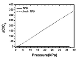
7 is a graph illustrating a change in capacitance of a capacitive tactile sensor according to an embodiment of the present invention.
8 is a graph illustrating a performance test of a capacitive tactile sensor according to an embodiment of the present invention.
9 is a graph illustrating a result of measuring various external pressures using a capacitive tactile sensor according to an embodiment of the present invention.
아래에서는 첨부한 도면을 참조하여 본 발명이 속하는 기술 분야에서 통상의 지식을 가진 자가 용이하게 실시할 수 있도록 본 발명의 실시예를 상세히 설명한다. 그러나 본 발명은 여러 가지 상이한 형태로 구현될 수 있으며 여기에서 설명하는 실시예에 한정되지 않는다. 그리고 도면에서 본 발명을 명확하게 설명하기 위해서 설명과 관계없는 부분은 생략하였으며, 명세서 전체를 통하여 유사한 부분에 대해서는 유사한 도면 부호를 붙였다.Hereinafter, embodiments of the present invention will be described in detail with reference to the accompanying drawings, which will be readily apparent to those skilled in the art. The present invention may, however, be embodied in many different forms and should not be construed as limited to the embodiments set forth herein. In order to clearly illustrate the present invention, parts not related to the description are omitted, and similar parts are denoted by like reference characters throughout the specification.
명세서 전체에서, 어떤 부분이 다른 부분과 "연결"되어 있다고 할 때, 이는 "직접적으로 연결"되어 있는 경우뿐 아니라, 그 중간에 다른 소자를 사이에 두고 "전기적으로 연결"되어 있는 경우도 포함한다. 또한 어떤 부분이 어떤 구성요소를 "포함"한다고 할 때, 이는 특별히 반대되는 기재가 없는 한 다른 구성요소를 제외하는 것이 아니라 다른 구성요소를 더 포함할 수 있는 것을 의미한다.Throughout the specification, when a part is referred to as being "connected" to another part, it includes not only "directly connected" but also "electrically connected" with another part in between . Also, when an element is referred to as "comprising ", it means that it can include other elements as well, without departing from the other elements unless specifically stated otherwise.
일반적으로, 사람 손끝의 피부는 10-40kPa의 압력 수준에서, 약 40μm의 공간 분해능으로 표면의 질감 및 온도를 동시에 감지한다. 따라서, 사람의 손끝의 면적이 약 1cm X 1cm라고 하면, 압력을 감지하는 센서의 개수는 62,500개로 각각의 센서가 압력을 실시간으로 측정하여 뇌로 전송하게 된다.Generally, at the pressure level of 10-40 kPa, the skin of a human fingertip simultaneously senses the texture and temperature of the surface with a spatial resolution of about 40 mu m. Therefore, when the area of the human fingertip is about 1
사람의 피부는 0.1 mm∼0.3 mm 두께의 표피(epidermis), 표피의 아래에 존재하는 진피(dermis), 및 피하지방으로 구성되어 있다. 이러한, 표피 및 진피에는 각종 물리량을 감지할 수 있는 수용기(receptor)들이 존재한다. 따라서, 외부와 신체의 여러 부위에서 일어나는 자극들은 이러한 수용기를 통해 감지되며, 수용기는 화학, 광학에너지를 전기신호로 바꾸어 감각신경을 통해 중추신경계로 전달한다. 이때, 수용기는 종류에 따라감지할 수 있는 감각들이 다르다. Human skin consists of epidermis with a thickness of 0.1 mm to 0.3 mm, dermis existing under the epidermis, and subcutaneous fat. These epidermis and dermis contain receptors capable of detecting various physical quantities. Thus, stimuli that occur in the outside and in various parts of the body are sensed through these receptors, and the receptors turn chemical, optical energy into electrical signals and transmit them to the central nervous system through the sensory nerves. At this time, receptors have different senses that can be detected depending on the kind.
일례로, 촉각을 감지하는 대표적인 수용기로 마이소너(Meissner) 소체, 머켈(Merkel) 수용기, 파시닌(Pacinian), 및 루피니(Ruffini) 소체 등이 있다. 마이소너(Meissner) 소체는 피부 움직임을 가장 잘 감지하며 피부의 표피와 진피 사이에 존재하는 머켈(Merkel) 수용기는 피부를 누르는 감각에 가장 잘 반응하고 진동에 대한 인식 기능을 일부 담당한다. 한편 파시닌(Pacinian) 소체는 피부의 가장 깊은 곳에 위치하고, 운동감과 미세한 접촉, 진동을 인식한다. 또한, 루피니(Ruffini) 소체도 피부의 깊은 곳에 위치하며 방추형 구조로 압력과 온도변화를 감지한다. For example, representative receptors for sensing tactile sensation include Meissner bodies, Merkel receptors, Pacinian, and Ruffini bodies. The Meissner organelles are the best detectable skin movements, and the Merkel receptors between the epidermis and the dermis of the skin respond best to the sensation of pressing the skin and are part of the perception of vibration. On the other hand, the Pacinian body is located deepest in the skin and recognizes motion, fine contact, and vibration. In addition, the Ruffini bodies are located deep in the skin, and the pressure and temperature changes are detected by the fusiform structure.
촉각센서의 관점에서 보면 사람의 피부는 각각의 물리량을 측정하는 능동형 센서(수용기, 뉴런)들이 점탄성을 갖는 물질(진피)에 박혀있는 형태이다.From the point of view of tactile sensors, human skin is a form in which active sensors (receptors, neurons) that measure each physical quantity are embedded in viscoelastic material (dermis).
따라서, 본 발명의 일 실시예는 사람의 피부에 존재하는 다양한 수용기 중 촉각이 예민한 부위에 발달되어 있는 머켈 셀을 모사하여, 모든 압력 범위를 민감하게 인지할 수 있는 탄성중합체 기반의 커패시터형 촉각센서를 제공하고자 한다. 이하, 도면을 참조하여 머켈 셀을 모사한 커패시터형 촉각센서에 대해 상세히 설명하도록 한다.Therefore, one embodiment of the present invention is an elastic polymer-based capacitor-type tactile sensor capable of sensitively recognizing all the pressure ranges by simulating a Merkel cell in which various tactile senses among the various receptors existing in human skin are developed. ≪ / RTI > Hereinafter, a capacitor type tactile sensor in which a Merkel cell is simulated will be described in detail with reference to the drawings.
도 1은 본 발명의 일 실시예에 의한 커패시터형 촉각센서와 머켈 셀에서의 이온교환 원리를 비교한 개념도이다. BRIEF DESCRIPTION OF THE DRAWINGS FIG. 1 is a conceptual diagram comparing a principle of ion exchange in a capacitive tactile sensor and a Merkel cell according to an embodiment of the present invention. FIG.
도 1의 (a)는 인간의 피부의 진피층을 도시한 도면이고, (b)는 외부 자극이 있기 전의 진피층 내의 머켈 셀의 상태를 도시한 도면이다. (c)는 외부에서 자극을 받았을 때의 머켈 셀의 내외부의 이온농도의 변화를 도시한 도면이다. FIG. 1 (a) is a view showing the dermis layer of human skin, and FIG. 1 (b) is a diagram showing the state of the Merkel cells in the dermal layer before external stimulation. (c) are diagrams showing changes in ion concentration in the inside and outside of the Merkel cell when they are stimulated externally.
도 1에 도시된 바와 같이, 외부의 물리인 자극에 의해, 머켈 셀 내부의 닫혀있던 채널이 열리게 되며, 이에 따라 외부에서 내부로 이온의 스퀴징(Squeezing)이 일어난다. As shown in FIG. 1, a closed channel inside the Merkel cell is opened by an external physical stimulus, thereby causing squeezing of ions from the outside to the inside.
이때, 머켈 셀 내부에 존재하는 채널은 피에조 타입의 기계수용 이온채널(Piezo-type mechanosensitive ion channel component 2, Piezo2)이며, 세포막의 물리적 자극에 의해 활성화되는 채널이다. 따라서, 기계적 자극에 의해 기계수용 이온채널이 활성화하면 양이온의 투과성이 높아져 막탈분극이 발생한다. 따라서, 물리적 자극은 수용기전위로 변환되며 중추에 신호가 전달된다. In this case, the channel inside the cell is a piezo-type mechanosensitive ion channel component 2 (Piezo 2), which is activated by physical stimulation of the cell membrane. Therefore, activation of the mechanical acceptance ion channel by mechanical stimulation increases the permeability of cations and leads to membrane depolarization. Thus, the physical stimulus is converted to the receptor potential and the signal is transmitted to the center.
도 1의 (d) 내지 (f)는 본 발명의 일 실시예에 따른 커패시터형 촉각센서의 개념도이다. 도 1의 (d)를 참조하면, 본 발명의 일 실시예에 따른 커패시터형 촉각센서는 활성층(300), 활성층(300)의 하부에 형성된 제 1 전극(200), 및 활성층(300)의 상부에 형성된 제 2 전극(400)을 포함한다. 이때, 활성층(300)으로서 이온성 탄성중합체로 형성된다. 이때, 활성층(300)의 형태의 제한은 없으며, 사각의 형상을 띨 수도 있고 도면의 가운데 및 오른쪽처럼 반구형일 수도 있다. 1 (d) to 1 (f) are conceptual diagrams of a capacitor-type tactile sensor according to an embodiment of the present invention. 1D, a capacitor-type tactile sensor according to an embodiment of the present invention includes an
도 1의 (e)는 반구형의 활성층(300)을 도시하고 있으며, 자극이 가해지기 전의 활성층(300) 및 제 2 전극(400)의 상태를 도시하고 있다. 더욱 상세하게, 활성층(300)은 양이온, 음이온, 하드 세그먼트(hard segment, 310), 및 소프트 세그먼트(soft segment, 320)를 포함하고 있다. 이때, 세그먼트들은 활성층(300) 내부에서 구역을 구획하고, 이온들을 격리할 수 있다. 또한, 자극이 가해지기 전, 활성층(300)의 상부에 형성된 제 2 전극(400)은 음전하를 띠고 있다.FIG. 1 (e) shows a hemispherical
본 발명의 일 실시예 따른 활성층(300)은 열가소성 폴리 우레탄과 이온성 액체의 매트릭스(IL/TPU)용액을 이용하여 형성될 수 있다. The
도 2는 본 발명의 일 실시예에서 고려되는 열가소성 폴리 우레탄 및 이온성 액체에 포함되는 이온의 일례를 도시하고 있다. 구체적으로, 도 2의 (a)는 열가소성 폴리 우레탄 구조를 도시하고 있으며, 도 2의 (b) 및 (c)는 이온성 액체에 포함되는 이온의 일례를 도시하고 있다. 도 2에 도시된 X는 할로겐(halogen) 원소를 나타내며, R은 알킬기(alkyl)를 나타낸다.Figure 2 shows an example of ions included in the thermoplastic polyurethane and ionic liquid considered in one embodiment of the present invention. Specifically, FIG. 2 (a) shows a thermoplastic polyurethane structure, and FIGS. 2 (b) and 2 (c) show examples of ions contained in an ionic liquid. X shown in Fig. 2 represents a halogen element, and R represents an alkyl group.
도 2에 도시된 바와 같이, 일반적으로, 열가소성 폴리 우레탄은 경직한 분자쇄인 하드 세그먼트와 유연한 구조의 소프트 세그먼트로 이루어진 세그먼티드 블럭 코폴리머(segmented block copolymer)로 구성된다.As shown in Fig. 2, in general, the thermoplastic polyurethane is composed of a segmented block copolymer composed of a hard segment which is a rigid molecular chain and a soft segment of a flexible structure.
하드 세그먼트는 상온보다 높은 유리전이온도(Tg)를 가진다. 따라서, 유리질(glassy)한 성질을 나타내는 하드 세그먼트간에 결정형성이나, 수소 결합, 또는 반데르발스 힘 등의 결합으로 인하여 물리적인 가교점을 형성한다. 반면, 소프트 세그먼트는 상온보다 낮은 유리전이온도를 가진다. 따라서, 러버(rubber)한 성질을 나타내는 탄성체가 나타내야 할 중요한 성질들, 즉 높은 연신비, 높은 탄성률, 높은 탄성 회복률 등을 부여하는 역할을 한다. 이러한 세그먼트들은 외력을 받으면 세그먼트의 배향뿐만 아니라 구조의 변화를 일으킬 수 있다.The hard segment has a glass transition temperature (Tg) higher than room temperature. Therefore, a physical crosslinking point is formed due to crystal formation, hydrogen bonding, van der Waals force or the like between hard segments showing glassy properties. On the other hand, the soft segment has a glass transition temperature lower than room temperature. Therefore, the elastomer exhibiting rubber properties plays a role in giving important properties to be exhibited, that is, high stretch ratio, high elastic modulus, high elastic recovery rate, and the like. These segments can cause structural changes as well as orientation of the segments upon receiving an external force.
다시 도 1의 (f)를 참조하면, 외부에서 제 2 전극(400)에서 활성층(300)의 방향으로 자극(압력)이 가해졌을때, 유연한 이온성 탄성중합체로 이루어진 활성층(300)은 외부의 자극에 의해서 모양이 변형된다. 또한, 반구형의 활성층(300)의 상단이 제 2 전극(400)과 접촉하면서 압력을 받아 모양이 변형된 것을 확인할 수 있다.Referring to FIG. 1F, when a stimulus (pressure) is applied from the
이때, 반구형의 활성층(300)의 상단이 제 2 전극(400)과 접촉하면서, 음전하를 띄고 있는 제 2 전극(400)의 주변으로 활성층(300) 내부의 양전하가 이동하게 된다. 또한, 활성층(300) 내부를 구획하고 있는 세그먼트들의 형상이 바뀌면서 세그먼트 내부에 격리되어 있던 이온들이 외부로 방출되게 된다. 이러한 현상은 도 1의 (c)에서 자극을 받았을 때 Piezo2 채널이 열리며 이온이 채널 안으로 스퀴징 되는 현상과 유사하다. At this time, the upper end of the hemispherical
도 3은 본 발명의 일 실시예에 따른 커패시터형 촉각센서의 구성 및 구동원리를 개략적으로 도시한 도면이다.FIG. 3 is a view schematically showing a configuration and a driving principle of a capacitor-type tactile sensor according to an embodiment of the present invention.
도 3 의 (a)와 (b)는 활성층이 사각 형상일 때의 압력 전, 후의 모습을 도시하고 있다.3 (a) and 3 (b) show the state before and after the pressure when the active layer has a rectangular shape.
먼저 도 3의 (a)를 참조하면, 본 발명의 일 실시예에 따른 커패시터형 촉각센서는 제 1 기판(100), 제 1 전극(200), 활성층(300), 제 2 전극(400), 및 제 2 기판(500)을 포함한다. 또한, 도시되어 있지는 않지만, 제 1 전극(200) 및 제 2 전극(400) 사이에 형성되는 커패시턴스를 검출하고, 커패시턴스에 따라 외부 압력을 감지하는 제어부를 더 포함할 수 있다.3 (a), a capacitor-type tactile sensor according to an exemplary embodiment of the present invention includes a
사용자의 목적에 따라서, 활성층(300)과 제 2 전극(400)의 사이는 처음부터 접촉이 되어 있을 수도 있고, 접촉되지 않은 상태로 소정의 간격을 두고 이격될 수도 있다.Depending on the purpose of the user, the
도 1의 (e)에서 전술한 바와 같이 활성층(300)은 세그먼트들을 포함하여, 세그먼트들이 활성층(300) 내부에서 구역을 구획하고, 일정 농도의 이온을 포획할 수 있다. As described above with reference to FIG. 1 (e), the
활성층(300)은 탄성을 가지고 있기 때문에 압력을 가해줌에 따라, 도시된 바와 같이 수축하게 된다. 외부 압력에 의하여 활성층(300)이 수축되면, 활성층(300)내의 세그먼트들의 모양이 변화하게 되고, 세그먼트들 내에 포획된 이온들이 세그먼트에서 활성층(300)으로 방출되게 된다. 따라서, 활성층(300)내에서의 커패시턴스 값에 유효한 유효 이온의 농도가 증가 된다.Since the
도 4는 본 발명의 다른 실시예에 따른 커패시터형 촉각센서의 구성 및 구동원리를 도시한 개념도이다.4 is a conceptual diagram showing a configuration and a driving principle of a capacitive tactile sensor according to another embodiment of the present invention.
도 4의 (a) 및 (b)는 필라 구조의 유닛 한 개에서 일어나는 현상을 도시하고 있다.Figures 4 (a) and 4 (b) show the phenomenon taking place in one unit of the pillared structure.
도 4를 참조하면, 활성층(300)이 반구형의 필라 구조의 커패시터형 촉각센서는, 외부의 압력의 세기에 따라서 접촉되는 면을 조절할 수 있으므로 사용자의 목적에 맞게 반구형의 모양을 설계할 수도 있다. 즉, 활성층(300)은 반구형의 필라 구조뿐 아니라 외부 압력에 따라 제 2 전극(500)과의 접촉면을 증가시킬 수 있는 요철 구조라면 어떤 형태든지 가능하다. Referring to FIG. 4, the capacitor-type tactile sensor having the hemispherical pillar structure of the
만약, 제 2 전극(400)에서 활성층(300)의 방향으로 외부의 압력이 가해지면, 가해진 압력의 크기에 따라, (b)와 같이 반구형의 필라 구조인 활성층(300)은 제 2 전극(400)과 일정부분이 접촉하게 된다.If an external pressure is applied in the direction of the
한편, 도 4의 (c)에 도시된 바와 같이, 상술한 유닛 한 개의 필라 구조는 어레이 형태로 배열될 수도 있다.On the other hand, as shown in Fig. 4 (c), the above-described unit pillar structure may be arranged in an array form.
도 4의 (d)는 본 발명의 다른 실시예에 따른 반구형의 필라 구조 유닛이 어레이 형태로 배열된 활성층을 포함하는 커패시터형 촉각센서의 단면을 도시하고 있다. 도 4의 (d)를 참조하면, 활성층(300)이 복수의 필라 구조가 어레이로 배치되어 구현된 경우, 외부에서 압력에 의해, 복수의 필라 구조의 활성층(300)이 변형될 수 있다. FIG. 4 (d) shows a cross section of a capacitor-type tactile sensor including an active layer in which hemispherical pillar structural units according to another embodiment of the present invention are arranged in an array form. Referring to FIG. 4 (d), when the
한편, 도 5를 함께 참조하여 본 발명의 일 실시예에 따른 커패시터형 촉각센서를 제조하는 방법과 각각의 구성이 갖는 기능에 대해서 보다 자세히 설명하도록 한다.5, a method of manufacturing a capacitor-type tactile sensor according to an embodiment of the present invention and functions of the respective structures will be described in detail.
도 5는 본 발명의 일 실시예에 따른 커패시터형 촉각센서의 제조 방법을 도시한 순서도이다.5 is a flowchart illustrating a method of manufacturing a capacitive tactile sensor according to an embodiment of the present invention.
도 5를 참조하면, 본 발명의 일 실시예에 따른 커패시터형 촉각센서를 제조하는 방법은 제 1 기판(100)의 상부면에 제 1 전극(200)을 형성하는 단계(S410), 제 1 전극(200)의 상부면에 활성층(300)을 형성하는 단계(S420), 활성층(300)의 상부면에 제 2 전극(400)을 형성하는 단계(S430), 및 제 2 전극의 상부면에 제 2 기판(500)을 배치하는 단계(S440)를 포함한다. Referring to FIG. 5, a method of manufacturing a capacitive tactile sensor according to an embodiment of the present invention includes forming a
경우에 따라, 활성층(300)과 제 2 전극(400)이 접촉되지 않은 경우에는 단계(S420)까지는 동일하게 공정을 한 후, 제 2 전극(400)과 제 2 기판(500)은 별도로 형성할 수 있다. 즉, 상술한 도5의 제 2 전극(400)을 형성하는 단계(S430), 및 제 2 전극의 상부면에 제 2 기판(500)을 배치하는 단계(S440)를 수행하는 순서는 도 5에 도시된 순서에 제한되지 않으며, 단계(s410) 내지 단계(s420)와 병렬로 이루어 질 수 있다.If the
참고로, 제 1 기판(100), 및 제 2 기판(500)은 커패시터형 촉각센서의 맨 아래층에 위치하는 구성요소로써, 유리, 세라믹, 실리콘, 고무 및 플라스틱 중 어느 하나로 이루어 질 수 있으나 이에 한정되는 것은 아니다. 이때, 제 1 기판(100), 및 제 2 기판(500)의 두께, 크기 및 형상은 다양하게 설정할 수 있다. 또한, 필요에 따라 생략할 수도 있다. 제 1 기판(100), 및 제 2 기판(500)은 각각 제 1 전극(200) 및 제 2 전극(400)과 접촉하여 지지하는 역할을 한다.The
먼저, 제 1 전극(200)을 형성하는 단계(S410)에서, 제 1 전극(200)이 일반적으로 반도체공정에서 수행되는 포토리소그래피 공정에 의하여 형성될 수 있다.First, in step S410 of forming the
더욱 상세하게, 제 1 기판(100)의 상부면에 열 증착법(thermal evaporation), 전자빔 증착법(e-beam evaporation), 및 스퍼터링 증착법(sputtering) 중 어느 한 증착법에 의하여 제 1 전극(200)을 형성하기 위한 물질이 형성될 수 있다. 이때, 제 1 전극(200)을 형성하기 위한 물질의 형성 방법은 상술한 방법에 한정되지는 않으며, 전사 혹은 조건에 따라 스프레이 코팅이나 베큠 필터레이션(Vacuum filteration), 및 전기방사도 가능하다. More specifically, the
제 1 전극(200)을 형성하는 물질은 금속, 전도성 산화 금속, 전도성 폴리머, 전도성 카본, 전도성 나노 입자 및 유기 물질이나 전도성 물질 사이에 삽입된 나노 입자에서 선택된 전극 물질일 수 있다. The material forming the
이이서, 원하는 모양의 전극을 제조하기 위해, 감광제를 코팅하고 마스크를 이용하여 특정 부분을 노광한 후, 패턴을 현상할 수 있다. 이후, 건식 또는 습식 식각 공정을 수행함으로써 원하는 형상의 전극을 형성할 수 있다. Then, in order to produce electrodes of a desired shape, a photosensitive agent may be coated and a specific portion may be exposed using a mask, and then the pattern may be developed. Thereafter, a dry or wet etching process is performed to form an electrode having a desired shape.
이어서, 단계 (S420)에서, 제 1 전극(200)의 상부면에 활성층(300)이 형성될 수 있다. 활성층(300)을 형성하는 방법은 일반적으로 몰딩법, 식각 공정, 스핀코팅 중 어느 한가지 방법으로도 가능하나, 이에 한정하지는 않는다. 본 발명의 일 실시예에 따른 활성층은 이온성 탄성중합체를 스핀코팅하여 간단히 제조할 수 있지만, 반구형과 같은 요철 구조로 활성층을 제조할 경우에는, 원하는 모양의 몰드(mold)에 액상의 이온성 탄성중합체를 경화시키는 방법을 이용하기도 한다. 이하, 도 6을 참조하여 활성층을 제조하는 방법을 예를 들어 상세히 설명하도록 한다. Then, in step S420, the
도 6은 본 발명의 다른 실시예에 따른 필러 구조의 활성층을 제조하는 방법을 도시한 개념도이다.6 is a conceptual diagram showing a method of manufacturing an active layer of a filler structure according to another embodiment of the present invention.
먼저, 도 6의 (a)와 같이, 액상의 이온성 탄성중합체를 준비한다. 본 발명의 일 실시예에 따른 활성층을 제조하는 방법은 열가소성 폴리 우레탄과 이온성 액체의 매트릭스(IL/TPU)용액을 이온성 탄성중합체로 사용하였다. 다음으로, 요철 구조의 몰드(mold)를 준비하고, 액상의 이온성 탄성중합체를 요철 구조의 몰드에 주입한다(b). 다음으로, 액상의 이온성 탄성중합체를 경화시키고, 경화된 이온성 탄성중합체를 몰드로부터 분리하면(c), 도 5의 (d)와 같이, 반구형의 필라 구조인 활성층(300)이 생성되게 된다.First, as shown in Fig. 6 (a), a liquid ionic elastomer is prepared. A method of producing an active layer according to an embodiment of the present invention uses a matrix (IL / TPU) solution of a thermoplastic polyurethane and an ionic liquid as an ionic elastomer. Next, a mold having a concave-convex structure is prepared, and a liquid ionic elastomer is injected into a mold having a concave-convex structure (b). Next, when the liquid ionomeric elastomer is cured and the cured ionic elastomer is separated from the mold (c), the
참고로, 이온성 액체는 상온에서 액체 상태로 존재하는 염으로 물질 자체가 이온들로만 구성되어 있어, 대략 10mS/cm의 높은 전도도와 4V이상의 넓은 전기화학창을 비롯하여 매우 낮은 휘발성을 갖는다. 이때, 이온성 액체의 점도는 물과 유사하다. 한편, TPU의 경우 투명하고, 탄성을 가지며, 이온성 액체와 블랜딩이 잘되고, 높은 이온전도도의 특성을 보유하고 있다.For reference, an ionic liquid is a salt present in a liquid state at room temperature. Since the material itself is composed of only ions, it has very high volatility including a high electroconductivity of about 10 mS / cm and a wide electrochemical window of 4V or more. At this time, the viscosity of the ionic liquid is similar to that of water. On the other hand, TPU is transparent, elastic, blends well with ionic liquids, and has high ionic conductivity.
따라서, 액상의 이온성 탄성중합체를 이용하여, 활성층(300)을 형성하였다. 이때, 활성층(300)은 세그먼트들이 포함되고, 세그먼트들은 하드 세그먼트 및 소프트 세그먼트를 포함한다. 이러한 세그먼트들은 활성층(300) 내부에서 구역을 구획하고, 일정한 농도의 이온들을 포획하는 역할을 한다. 따라서, 외부 압력이 가해지면, 세그먼트들의 구획된 영역이 변형되면서 이온을 활성층(300)으로 출납시킬 수 있다. 여기서, 이온이 출납되는 것은 머켈 셀의 세포막에서 이온이 스퀴징 되는 원리를 모사하였다.위와 같이, 외부 압력에 따라 활성층(300)내에서의 유효 이온의 농도가 조절되고, 그에 따라 커패시터형 촉각센서의 커패시턴스 값이 조절된다.다시 도 5를 참조하면, 제 1 전극(200)의 상부면에 활성층(300)을 형성한 후, 활성층(300)의 상부면에 제 2 전극(400)을 형성할 수 있다(S430). 이때, 활성층(300)의 상부면에 제 2 전극(400)을 형성하는 방법은 전술한 제 1 전극(200)의 제조 방법과 동일하다.Thus, the
한편, 활성층(300)의 상부 및 하부에 형성된 제 1 전극(200) 및 제 2 전극(400)은 제어부(미도시)로부터 전기 신호를 입력 받고, 이로 인해 전위차가 인가되어 나타나는 커패시턴스의 변화를 측정하거나 저항을 측정할 수 있다. 마지막으로, 단계 (S440)에서, 제 2 전극의 상부면에 제 2 기판(500)을 배치한다. 제 2 기반(500)에 대한 설명은 전술한 제 1 기판과 동일하므로 생략하기로 한다. 전술한 바와 같이, 도 5의 제 2 전극(400)을 형성하는 단계(S430)는 병렬로 이루어 질 수 있다. 따라서, 제 2 전극(400)과 제 2 기판(500)을 별도로 형성하여 활성층(300)의 상부에 배치시킬 수 있다. The
도 7은 본 발명의 일 실시예에 따른 커패시터형 촉각센서의 압력에 따른 커패시턴스의 변화를 측정한 그래프이다.7 is a graph illustrating a change in capacitance of a capacitive tactile sensor according to an embodiment of the present invention.
TPU와 이온성 TPU를 비교하였을 때, 본 발명의 일 실시예에 의한 이온성 TPU는 압력이 증가될수록 커패시턴스의 값이 증가되는 것을 확인하였으나, 기존 TPU는 커패시턴스의 변화가 거의 없는 것을 확인하였다.When comparing the TPU with the ionic TPU, it was confirmed that the capacitance of the ionic TPU according to an embodiment of the present invention increases as the pressure is increased. However, it is confirmed that the capacitance of the conventional TPU hardly changes.
이는 활성층(300)으로 사용된 이온성 TPU에 압력이 가해지면, 내부의 세그먼트들의 변형이 일어나 포획되어 있는 이온이 방출되게 되고, 활성층(300)의 표면의 유효 이온의 농도가 증가되어, 표면의 이온수가 증가되기 때문이다. 이때, 증가된 표면의 이온수는 정전 용량을 증가시켜 전기적 신호로 전달되게 된다.When the pressure is applied to the ionic TPU used as the
또한, 도 7의 그래프를 통해, 본 발명의 일 실시예에 따른 커패시터형 촉각센서가 설정한 측정 범위의 압력 영역에서 측정가능 하다는 것을 확인하였다.Also, it is confirmed through the graph of FIG. 7 that the capacitor-type tactile sensor according to an embodiment of the present invention can measure in the pressure range of the measurement range set.
도 8은 본 발명의 일 실시예에 따른 커패시터형 촉각센서의 성능을 테스트한 그래프이다.8 is a graph illustrating a performance test of a capacitive tactile sensor according to an embodiment of the present invention.
도 8의 (a)와 (b)는 본 발명의 일 실시예에 따른 커패시터형 촉각센서의 특정 압력에 대한 응답성을 나타내고 있다. (a)의 경우, 100Pa, 1kPa, 및 10kPa의 압력으로 일정 주기 반복해서 자극을 주었을 때의 커패시턴스의 변화이다. 그래프를 참조하면, 100Pa의 경우에는 1kPa 이나 10kPa 보다는 변화가 미약하기는 하나 일정한 그래프 개형을 보인다. 1kPa 정도의 압력을 가했을 경우, 10kPa의 압력을 가했을 경우에 비하여 약 3배 큰 커패시턴스의 변화를 보이고, 각각은 자극에 대해 일정한 변화폭을 가진다. 이로 인해, 반복적인 힘을 가해주었을 때도 본 발명의 일 실시예에 따른 커패시터형 촉각센서의 신뢰성이 확보된다는 것을 알 수 있다.8 (a) and 8 (b) show the responsiveness of the capacitor-type tactile sensor according to an embodiment of the present invention to a specific pressure. (a) is a change in capacitance when a stimulus is applied repeatedly at a constant pressure of 100 Pa, 1 kPa, and 10 kPa. Referring to the graph, the change of 100 Pa is smaller than that of 1 kPa or 10 kPa, but shows a constant graph shape. When a pressure of about 1 kPa is applied, the capacitance change is about three times larger than that when a pressure of 10 kPa is applied, and each of the capacitances changes with respect to the stimulation. Accordingly, it can be seen that the reliability of the capacitor-type tactile sensor according to the embodiment of the present invention is assured even when repetitive force is applied.
더욱이, 도 8의 (b)는 본 발명의 일 실시예에 따른 커패시터형 촉각센서의 반복 응답성을 확인한 그래프이다. 1N의 힘으로 360초 동안 일정 주기 반복해서 외력을 가했을 때의 커패시턴스의 변화 값이 일정한 것을 확인하였다.8 (b) is a graph showing the repeatability of the capacitor-type tactile sensor according to an embodiment of the present invention. It was confirmed that the change value of the capacitance when the external force was applied repeatedly for a predetermined period of 360 seconds with a force of 1 N was constant.
또한, 도 8의 (c)는 본 발명의 일 실시예에 따른 커패시터형 촉각센서의 활성층(300)이 반구형 필라구조로 패턴된 TPU인 경우(Patterned TPU, 빨간색), 반구형 필라구조이면서 이온성 TPU인 경우(Patterned Ionic TPU, 파란색), 필라구조가 아닌 TPU인 경우(Pristine TPU, 검은색), 및 필라구조가 아니고 이온성 TPU인 경우(Pristine Ionic, 녹색)에 압력에 따른 커패시턴스의 변화를 측정한 그래프이다.8C shows a case where the
도 8의 (c)에서는 본 발명의 일 실시예에 따른 이온성 TPU를 활성층(300)으로 사용한 경우(파란색, 녹색)가 압력에 따른 커패시턴스의 변화가 크게 나타났으며, 필라구조의 여부에 상관없이 이온성이 아닌 일반 TPU를 활성층(300)으로 사용한 경우(빨간색, 검은색)에는 압력에 따른 커패시턴스의 변화가 거의 없었다.In FIG. 8 (c), when the ionic TPU according to an embodiment of the present invention is used as the active layer 300 (blue, green), a change in the capacitance depending on the pressure is significant, , There was almost no change in the capacitance depending on the pressure when the general TPU which is not ionic was used as the active layer 300 (red, black).
또한, 이온성 TPU를 활성층(300)으로 사용하면서, 필라구조의 여부에 따라서 필라구조가 있는 경우(파란색)의 압력에 따른 커패시턴스의 변화가 크게 나타나는 것을 알 수 있다.In addition, it can be seen that, when the ionic TPU is used as the
도 9는 본 발명의 일 실시예에 따른 커패시터형 촉각센서를 이용하여 외부의 다양한 압력을 측정한 결과 그래프이다.9 is a graph illustrating a result of measuring various external pressures using a capacitive tactile sensor according to an embodiment of the present invention.
도 9의 (a)는 스피커를 이용하여, ‘도’음(좌) 또는 아리랑(우)을 들려주었을 때, 본 발명의 일 실시예에 따른 커패시터형 촉각센서에서 측정된 커패시턴스값의 변화를 보여준다. 이를 통해, 커패시터형 촉각센서를 향후 인공고막으로 활용할 수 있는 가능성을 확인할 수 있었다. 또한, (b)는 핸드폰의 수화기의 진동을 통해 ‘You raise me up’을 들려주었을 때의 결과이고, 이를 통해, 인공성대로서 활용할 수 있을 것이다. (c)는 커패시터형 촉각센서를 사람의 관자놀이에 부착하여, 맥박을 측정한 결과 그래프이고, (d)는 손가락에 부착하여 키보드를 타이핑한 결과를 보여준다. 이를 통해, 본 발명의 일 실시예에 따른 커패시터형 촉각센서가 다양한 외부의 압력을 측정할 수 있는 것을 확인하였다.9A shows a change in capacitance value measured by a capacitive tactile sensor according to an embodiment of the present invention when a speaker is used to listen to 'T' (left) or Arirang (right) . As a result, it was confirmed that the capacitor type tactile sensor could be utilized as a artificial eardrum in the future. In addition, (b) is a result of 'You raise me up' through the vibration of the handset, so that it can be utilized as an artificial vocal cords. (c) shows a result obtained by attaching a capacitor type tactile sensor to a human temple, and FIG. 10 (d) shows a result of typing a keyboard attached to a finger. Accordingly, it has been confirmed that the capacitor-type tactile sensor according to an embodiment of the present invention can measure various external pressures.
또한, 도면에 나타내지는 않았지만 본 발명의 일 실시예에 따른 커패시터형 촉각센서는 최소 10.33Pa의 압력인지 한계를 갖고 있다. 이것은 커패시터의 변화를 측정하였을 때, 측정 가능한 최소한의 압력이다.Also, although not shown in the drawings, the capacitive tactile sensor according to an embodiment of the present invention has a pressure limit of at least 10.33 Pa. This is the minimum measurable pressure when measuring changes in the capacitor.
전술한 본 발명의 설명은 예시를 위한 것이며, 본 발명이 속하는 기술분야의 통상의 지식을 가진 자는 본 발명의 기술적 사상이나 필수적인 특징을 변경하지 않고서 다른 구체적인 형태로 쉽게 변형이 가능하다는 것을 이해할 수 있을 것이다. 그러므로 이상에서 기술한 실시예들은 모든 면에서 예시적인 것이며 한정적이 아닌 것으로 이해해야만 한다. 예를 들어, 단일형으로 설명되어 있는 각 구성 요소는 분산되어 실시될 수도 있으며, 마찬가지로 분산된 것으로 설명되어 있는 구성 요소들도 결합된 형태로 실시될 수 있다.It will be understood by those skilled in the art that the foregoing description of the present invention is for illustrative purposes only and that those of ordinary skill in the art can readily understand that various changes and modifications may be made without departing from the spirit or essential characteristics of the present invention. will be. It is therefore to be understood that the above-described embodiments are illustrative in all aspects and not restrictive. For example, each component described as a single entity may be distributed and implemented, and components described as being distributed may also be implemented in a combined form.
본 발명의 범위는 상기 상세한 설명보다는 후술하는 특허청구범위에 의하여 나타내어지며, 특허청구범위의 의미 및 범위 그리고 그 균등 개념으로부터 도출되는 모든 변경 또는 변형된 형태가 본 발명의 범위에 포함되는 것으로 해석되어야 한다.The scope of the present invention is defined by the appended claims rather than the detailed description and all changes or modifications derived from the meaning and scope of the claims and their equivalents are to be construed as being included within the scope of the present invention do.
100: 제 1 기판
200: 제 1 전극
300: 활성층
400: 제 2 전극
500: 제 2 기판100: first substrate
200: first electrode
300: active layer
400: second electrode
500: second substrate
Claims (13)
제 1 전극;
상기 제 1 전극의 상부면에 형성된 활성층; 및
상기 활성층의 상부면에 형성된 제 2 전극을 포함하되,
상기 활성층은 탄성중합체와 이온성 액체를 포함하여 이루어진 이온성 탄성중합체로 이루어진 것이고,
상기 활성층은 그 내부에 상기 활성층을 구획하고, 일정한 농도의 이온들을 격리하는 세그먼트들을 포함하고, 외부 압력에 의하여 압력이 가해진 활성층 표면에서의 유효 이온의 농도가 조절되는 것이되,
상기 세그먼트들은 상기 외부 압력에 따라 상기 구획된 영역이 변형되어 상기 격리된 이온들을 상기 활성층으로 출납하고, 출납된 이온에 의하여 정전용량이 증가하는 것인 커패시터형 촉각센서.In a capacitive tactile sensor,
A first electrode;
An active layer formed on an upper surface of the first electrode; And
And a second electrode formed on an upper surface of the active layer,
Wherein the active layer is made of an ionic elastomer comprising an elastomer and an ionic liquid,
The active layer includes segments for partitioning the active layer into the active layer and isolating a predetermined concentration of ions. The concentration of effective ions on the surface of the active layer, to which the external pressure is applied, is controlled.
Wherein the segments are deformed in accordance with the external pressure to deposit the isolated ions into and out of the active layer, and the electrostatic capacity is increased by the introduced ions.
상기 외부 압력에 따라
상기 유효 이온의 농도가 조절되고, 상기 유효 이온의 농도의 조절에 따라 상기 커패시터형 촉각센서의 커패시터 값이 조절되는 것인 커패시터형 촉각센서. The method according to claim 1,
Depending on the external pressure
Wherein the concentration of the effective ions is adjusted and the value of the capacitor of the capacitor-type tactile sensor is adjusted according to the adjustment of the concentration of the effective ions.
상기 활성층의 상부면은 요철 구조로 형성된 것이고,
상기 외부 압력에 따라 상기 제 2 전극과의 접촉면이 증가되며, 상기 접촉면의 증가에 따라 유효 이온의 농도가 증가되는 것을 포함하는 커패시터형 촉각센서.The method according to claim 1,
The upper surface of the active layer is formed in a concavo-convex structure,
Wherein the contact surface with the second electrode is increased according to the external pressure, and the concentration of the effective ions is increased as the contact surface is increased.
상기 활성층의 상부면에 형성되고,
반구형의 구조물이 복수개 배치된 커패시터형 촉각센서.The method according to claim 1,
A first electrode formed on the upper surface of the active layer,
A capacitor-type tactile sensor comprising a plurality of hemispherical structures.
상기 세그먼트들은
하드 세그먼트(hard segment), 및 소프트 세그먼트(soft segment)를 포함하고,
상기 외부 압력에 따라 상기 세그먼트들은 머켈 셀(Merkel cell)의 세포막에서 이온이 스퀴징(squeezing)되는 원리를 모사하여 이온을 출납시키는 것을 포함하는 커패시터형 촉각센서.The method according to claim 1,
The segments
A hard segment, and a soft segment,
And wherein said segments according to said external pressure simulate the principle that ions are squeezed in the cell membrane of a Merkel cell to deposit and withdraw ions.
상기 활성층으로 사용된 이온성 탄성 중합체는
열가소성 폴리 우레탄과 이온성 액체의 매트릭스(IL/TPU)용액을 포함하는 커패시터형 촉각센서.The method according to claim 1,
The ionic elastomer used as the active layer
A capacitive tactile sensor comprising a thermoplastic polyurethane and a matrix (IL / TPU) solution of an ionic liquid.
상기 제 1 전극과 접촉하는 제 1 기판; 및
상기 제 2 전극과 접촉하는 제 2 기판을 더 포함하는 커패시터형 촉각센서.The method according to claim 1,
A first substrate in contact with the first electrode; And
And a second substrate in contact with the second electrode.
상기 제 1 전극 및 제 2 전극 사이에 형성되는 커패시턴스를 검출하고, 상기 커패시턴스에 따라 외부 압력을 감지하는 제어부를 더 포함하는 커패시터형 촉각센서.The method according to claim 1,
And a control unit for detecting a capacitance formed between the first electrode and the second electrode and sensing an external pressure according to the capacitance.
제 1 기판의 상부면에 제 1 전극을 형성하는 단계;
상기 제 1 전극의 상부면에 활성층을 형성하는 단계;
상기 활성층의 상부면에 제 2 전극을 형성하는 단계; 및
상기 제 2 전극의 상부면에 제 2 기판을 배치하는 단계를 포함하되,
상기 활성층은 탄성중합체와 이온성 액체를 포함하여 이루어진 이온성 탄성중합체로 이루어진 것이고, 상기 활성층은 그 내부에 상기 활성층을 구획하고, 일정한 농도의 이온들을 격리하는 세그먼트들을 포함하고, 외부 압력에 의하여 압력이 가해진 활성층 표면에서의 유효 이온의 농도가 조절되는 것이고, 상기 세그먼트들은 상기 외부 압력에 따라 상기 구획된 영역이 변형되어 상기 격리된 이온들을 상기 활성층으로 출납하고, 출납된 이온에 의하여 정전용량이 증가하는 커패시터형 촉각센서의 제작 방법.A method of manufacturing a capacitive tactile sensor,
Forming a first electrode on an upper surface of the first substrate;
Forming an active layer on a top surface of the first electrode;
Forming a second electrode on an upper surface of the active layer; And
And disposing a second substrate on an upper surface of the second electrode,
Wherein the active layer is comprised of an ionic elastomer comprising an elastomer and an ionic liquid, the active layer includes segments therein for isolating the active layer and isolating ions of a constant concentration, The segments are subjected to deformation of the segmented region according to the external pressure to deposit and discharge the isolated ions into the active layer and to increase the capacitance by the introduced ions Wherein said capacitor-type tactile sensor comprises:
상기 활성층을 형성하는 단계는
액상의 이온성 탄성중합체를 요철 구조의 몰드(mold)에 주입하는 단계;
상기 액상의 이온성 탄성중합체를 경화하는 단계; 및
상기 경화된 이온성 탄성중합체를 몰드로부터 분리하는 단계를 포함하는 커패시터형 촉각센서의 제작 방법.11. The method of claim 10,
The step of forming the active layer
Injecting a liquid ionic elastomer into a mold of a concave-convex structure;
Curing the liquid ionic elastomer; And
And separating the cured ionic elastomer from the mold.
상기 요철 구조의 몰드는 반구형의 구조물의 형성을 위한 홈을 포함하는 커패시터형 촉각센서의 제작 방법.12. The method of claim 11,
Wherein the mold of the concave-convex structure includes a groove for forming a hemispherical structure.
상기 요철 구조의 몰드는 반구형의 구조물이 어레이 형태로 배치되도록 형성된 복수의 홈을 포함하는 것인 커패시터형 촉각센서의 제작 방법.12. The method of claim 11,
Wherein the mold of the concave-convex structure includes a plurality of grooves formed such that hemispherical structures are arranged in an array form.
Priority Applications (4)
| Application Number | Priority Date | Filing Date | Title |
|---|---|---|---|
| KR1020150122502A KR101742240B1 (en) | 2015-08-31 | 2015-08-31 | Tactile sensor and method for manufacturing the same |
| CN201610739566.5A CN106484201B (en) | 2015-08-31 | 2016-08-26 | Tactile sensor and method for manufacturing the same |
| EP16185887.3A EP3139255A1 (en) | 2015-08-31 | 2016-08-26 | Tactile sensor and method for manufacturing the same |
| US15/249,592 US10164632B2 (en) | 2015-08-31 | 2016-08-29 | Ionic elastomer based capacitor type tactile sensor and method for manufacturing the same |
Applications Claiming Priority (1)
| Application Number | Priority Date | Filing Date | Title |
|---|---|---|---|
| KR1020150122502A KR101742240B1 (en) | 2015-08-31 | 2015-08-31 | Tactile sensor and method for manufacturing the same |
Publications (2)
| Publication Number | Publication Date |
|---|---|
| KR20170025694A KR20170025694A (en) | 2017-03-08 |
| KR101742240B1 true KR101742240B1 (en) | 2017-06-01 |
Family
ID=56896343
Family Applications (1)
| Application Number | Title | Priority Date | Filing Date |
|---|---|---|---|
| KR1020150122502A Active KR101742240B1 (en) | 2015-08-31 | 2015-08-31 | Tactile sensor and method for manufacturing the same |
Country Status (4)
| Country | Link |
|---|---|
| US (1) | US10164632B2 (en) |
| EP (1) | EP3139255A1 (en) |
| KR (1) | KR101742240B1 (en) |
| CN (1) | CN106484201B (en) |
Cited By (3)
| Publication number | Priority date | Publication date | Assignee | Title |
|---|---|---|---|---|
| KR102352961B1 (en) | 2020-08-14 | 2022-01-20 | 한국생산기술연구원 | Physical sensor using polymer composite layered structure mixed with carbon nanotubes and method for manufacturing same |
| KR20220077811A (en) * | 2020-12-02 | 2022-06-09 | 포항공과대학교 산학협력단 | Stretchable sensor for sensing multimodal temperature and strain, electronic skin, and method of fabricating same |
| KR20250123447A (en) | 2024-02-08 | 2025-08-18 | 고려대학교 산학협력단 | Biological skin-mimicking multimodal integrated tactile sensor and integrated tactile system with the same |
Families Citing this family (20)
| Publication number | Priority date | Publication date | Assignee | Title |
|---|---|---|---|---|
| WO2017049007A1 (en) * | 2015-09-15 | 2017-03-23 | Interlink Electronics, Inc. | Multi-modal vehicle door handle |
| KR101876438B1 (en) * | 2017-08-10 | 2018-07-10 | 숭실대학교산학협력단 | Capacitor type tactile sensor based on viscoporoelastic elastomer |
| KR102042856B1 (en) * | 2018-04-27 | 2019-11-11 | 경희대학교 산학협력단 | Nanofiber web piezocapacitive sensor and fabricating method of the same |
| CN108613757B (en) * | 2018-05-07 | 2021-05-25 | 吉林大学 | A flexible capacitive tactile sensor based on biomaterial chitosan film and preparation method thereof |
| KR102476615B1 (en) * | 2018-10-22 | 2022-12-09 | 한양대학교 산학협력단 | Capacitor-type pressure sensor and method for fabricating the same |
| CN109323782B (en) * | 2018-10-26 | 2023-09-08 | 河北工业大学 | A non-array supercapacitive tactile sensor and its application |
| WO2020133416A1 (en) * | 2018-12-29 | 2020-07-02 | 钛深科技(深圳)有限公司 | Ionic rubber elastomer and preparation method therefor, and iontronic electronic skin |
| CN114026440A (en) * | 2019-06-14 | 2022-02-08 | 乔伊森安全系统收购有限责任公司 | Apparatus and method for producing sensing substrate |
| US11001167B2 (en) | 2019-06-14 | 2021-05-11 | Joyson Safety Systems Acquisition Llc | Apparatus and method of producing a sensing substrate |
| CN111504521B (en) * | 2020-05-07 | 2021-09-03 | 腾讯科技(深圳)有限公司 | Flexible capacitor array, preparation method thereof and capacitor array detection system |
| CN112729662B (en) * | 2020-12-10 | 2023-01-06 | 中国科学院深圳先进技术研究院 | Underwater tactile sensor and its preparation method |
| WO2022120795A1 (en) * | 2020-12-11 | 2022-06-16 | 中国科学院深圳先进技术研究院 | Three-dimensional force tactile sensor |
| KR102458295B1 (en) * | 2021-01-13 | 2022-10-24 | 한국과학기술원 | Biomimetic tactile sensor and manufacturing method thereof |
| KR20220118086A (en) * | 2021-02-18 | 2022-08-25 | 한국과학기술원 | Pressure sensing device for large area pressure sensing |
| CN113696391B (en) * | 2021-09-09 | 2022-07-05 | 天津工业大学 | Preparation method of microneedle ionic gel pressure sensing device |
| CN113965193B (en) * | 2021-10-20 | 2025-11-25 | 维沃移动通信有限公司 | Buttons and electronic devices |
| CN114112119A (en) * | 2021-11-19 | 2022-03-01 | 河北工业大学 | Microstructured touch sensor based on pseudo-capacitance principle and preparation method thereof |
| WO2023108424A1 (en) * | 2021-12-14 | 2023-06-22 | 中国科学院深圳先进技术研究院 | Integrated sensor for monitoring underwater contact pressure and depth of water |
| CN114690906A (en) * | 2022-04-12 | 2022-07-01 | 深圳市松果体机器人科技有限公司 | Controller based on touch |
| CN119666203B (en) * | 2025-02-20 | 2025-04-22 | 吉林大学 | Linear interval adjustable off-type flexible pressure sensor and preparation method thereof |
Citations (2)
| Publication number | Priority date | Publication date | Assignee | Title |
|---|---|---|---|---|
| JP2007037867A (en) | 2005-08-05 | 2007-02-15 | Asahi Kasei Corp | Fibroblast removal filter |
| WO2010005992A1 (en) * | 2008-07-07 | 2010-01-14 | Biomimedica, Inc. | Hydrophilic interpenetrating polymer networks derived from hydrophobic polymers |
Family Cites Families (15)
| Publication number | Priority date | Publication date | Assignee | Title |
|---|---|---|---|---|
| JPH0750689Y2 (en) | 1991-10-18 | 1995-11-15 | イナバゴム株式会社 | Pressure sensor |
| US6809462B2 (en) * | 2000-04-05 | 2004-10-26 | Sri International | Electroactive polymer sensors |
| EP1437584A1 (en) * | 2003-01-07 | 2004-07-14 | IEE INTERNATIONAL ELECTRONICS & ENGINEERING S.A. | Pressure transducer with elastic sensor layer, the surface of which is micro structured |
| ES2398525T3 (en) * | 2003-09-03 | 2013-03-19 | Sri International | Electroactive polymer transducers for surface deformation |
| US20100288635A1 (en) * | 2008-01-28 | 2010-11-18 | Kuraray Co., Ltd. | Flexible deformation sensor |
| EP2239793A1 (en) * | 2009-04-11 | 2010-10-13 | Bayer MaterialScience AG | Electrically switchable polymer film structure and use thereof |
| KR101423856B1 (en) * | 2010-10-13 | 2014-07-25 | 도카이 고무 고교 가부시키가이샤 | Flexible conductive material and transducer, flexible circuit board, and electromagnetic shield using said flexible conductive material |
| KR20130022544A (en) * | 2011-08-25 | 2013-03-07 | 삼성전기주식회사 | Capacitive pressure sensor and input device including thereof |
| KR102046377B1 (en) | 2011-09-24 | 2019-11-19 | 프레지던트 앤드 펠로우즈 오브 하바드 칼리지 | Artificial skin and elastic strain sensor |
| US9235265B2 (en) * | 2012-05-17 | 2016-01-12 | Sharp Kabushiki Kaisha | Touch-screen device including tactile feedback actuator |
| JP5497222B2 (en) * | 2012-09-28 | 2014-05-21 | バンドー化学株式会社 | Capacitance type sensor sheet and method for manufacturing capacitance type sensor sheet |
| WO2014169119A1 (en) * | 2013-04-10 | 2014-10-16 | President And Fellows Of Harvard College | Stretchable ionics for transparent sensors and actuators |
| JP2015088332A (en) * | 2013-10-30 | 2015-05-07 | パナソニックIpマネジメント株式会社 | Pressure-sensitive switch and manufacturing method thereof, touch panel including pressure-sensitive switch and manufacturing method thereof |
| US10126191B2 (en) * | 2015-08-28 | 2018-11-13 | The Regents Of The University Of California | Capacitive pressure sensing using ionic film sensors |
| US10401241B2 (en) * | 2016-06-08 | 2019-09-03 | The University Of British Columbia | Surface sensor arrays using ionically conducting material |
-
2015
- 2015-08-31 KR KR1020150122502A patent/KR101742240B1/en active Active
-
2016
- 2016-08-26 EP EP16185887.3A patent/EP3139255A1/en not_active Ceased
- 2016-08-26 CN CN201610739566.5A patent/CN106484201B/en active Active
- 2016-08-29 US US15/249,592 patent/US10164632B2/en active Active
Patent Citations (2)
| Publication number | Priority date | Publication date | Assignee | Title |
|---|---|---|---|---|
| JP2007037867A (en) | 2005-08-05 | 2007-02-15 | Asahi Kasei Corp | Fibroblast removal filter |
| WO2010005992A1 (en) * | 2008-07-07 | 2010-01-14 | Biomimedica, Inc. | Hydrophilic interpenetrating polymer networks derived from hydrophobic polymers |
Cited By (4)
| Publication number | Priority date | Publication date | Assignee | Title |
|---|---|---|---|---|
| KR102352961B1 (en) | 2020-08-14 | 2022-01-20 | 한국생산기술연구원 | Physical sensor using polymer composite layered structure mixed with carbon nanotubes and method for manufacturing same |
| KR20220077811A (en) * | 2020-12-02 | 2022-06-09 | 포항공과대학교 산학협력단 | Stretchable sensor for sensing multimodal temperature and strain, electronic skin, and method of fabricating same |
| KR102504686B1 (en) | 2020-12-02 | 2023-03-02 | 포항공과대학교 산학협력단 | Stretchable sensor for sensing multimodal temperature and strain, electronic skin, and method of fabricating same |
| KR20250123447A (en) | 2024-02-08 | 2025-08-18 | 고려대학교 산학협력단 | Biological skin-mimicking multimodal integrated tactile sensor and integrated tactile system with the same |
Also Published As
| Publication number | Publication date |
|---|---|
| EP3139255A1 (en) | 2017-03-08 |
| CN106484201A (en) | 2017-03-08 |
| US10164632B2 (en) | 2018-12-25 |
| KR20170025694A (en) | 2017-03-08 |
| US20170059417A1 (en) | 2017-03-02 |
| CN106484201B (en) | 2020-03-20 |
Similar Documents
| Publication | Publication Date | Title |
|---|---|---|
| KR101742240B1 (en) | Tactile sensor and method for manufacturing the same | |
| KR101876438B1 (en) | Capacitor type tactile sensor based on viscoporoelastic elastomer | |
| Amoli et al. | Biomimetics for high-performance flexible tactile sensors and advanced artificial sensory systems | |
| US7673528B2 (en) | Flexible modular sensor systems | |
| US10357201B2 (en) | Appendage mountable electronic devices conformable to surfaces | |
| CN108139282B (en) | Method and apparatus relating to a sensitive force sensor | |
| US12196626B2 (en) | Sensor apparatus for normal and shear force differentiation | |
| US12492955B2 (en) | Devices and methods involving sensing in response to an applied touch or other force | |
| Han et al. | Sensitive, stretchable, and breathable pressure sensors based on medical gauze integrated with silver nanowires and elastomers | |
| CN111352525A (en) | A low pressure capacitive tactile sensor and preparation method thereof | |
| CN104897317B (en) | Flexible contact pressing based on biomimetic features feels sensor | |
| JP2023511020A (en) | FLEXIBLE CAPACITOR ARRAY AND MANUFACTURING METHOD THEREOF, CAPACITOR ARRAY DETECTION SYSTEM AND ROBOT | |
| Huang et al. | A bioinspired MXene-based flexible sensory neuron for tactile near-sensor computing | |
| CN110487450B (en) | A kind of flexible tactile sensor and its preparation method and application | |
| KR102557279B1 (en) | Tactile sensor | |
| US20210313529A1 (en) | Internal-ion gated electrochemical transistors | |
| Ma et al. | Soft, multifunctional, robust film sensor using a ferroelectret with significant longitudinal and transverse piezoelectric activity for biomechanical monitoring | |
| Choi et al. | Bio-inspired ionic sensors: Transforming natural mechanisms into sensory technologies | |
| Chen et al. | Microstructured polyfluoroacrylate elastomeric dielectric layer for highly stretchable wide-range capacitive pressure sensors | |
| Jiang et al. | Triboelectric and iontronic dual-responsive bioinspired ionic skin for human–like dexterous robotic manipulation | |
| Gong et al. | Bioinspired adaptive sensors: a review on current developments in theory and application | |
| US11885141B2 (en) | Sensory flooring system and a sensory floor comprising a sensory flooring system | |
| CN115112268A (en) | Tactile sensor and method for manufacturing same | |
| Jiang et al. | Tactile sensor array with tertiary leaf-vein structures and position-encoded capacity | |
| KR102795193B1 (en) | Transistor simulating tactile function and method for manufacturing the same, artificial tactile system |
Legal Events
| Date | Code | Title | Description |
|---|---|---|---|
| A201 | Request for examination | ||
| PA0109 | Patent application |
Patent event code: PA01091R01D Comment text: Patent Application Patent event date: 20150831 |
|
| PA0201 | Request for examination | ||
| E902 | Notification of reason for refusal | ||
| PE0902 | Notice of grounds for rejection |
Comment text: Notification of reason for refusal Patent event date: 20160923 Patent event code: PE09021S01D |
|
| PG1501 | Laying open of application | ||
| E701 | Decision to grant or registration of patent right | ||
| PE0701 | Decision of registration |
Patent event code: PE07011S01D Comment text: Decision to Grant Registration Patent event date: 20170428 |
|
| GRNT | Written decision to grant | ||
| PR0701 | Registration of establishment |
Comment text: Registration of Establishment Patent event date: 20170525 Patent event code: PR07011E01D |
|
| PR1002 | Payment of registration fee |
Payment date: 20170526 End annual number: 3 Start annual number: 1 |
|
| PG1601 | Publication of registration | ||
| PR1001 | Payment of annual fee |
Payment date: 20200423 Start annual number: 4 End annual number: 4 |
|
| PR1001 | Payment of annual fee |
Payment date: 20210329 Start annual number: 5 End annual number: 5 |
|
| PR1001 | Payment of annual fee |
Payment date: 20230321 Start annual number: 7 End annual number: 7 |
|
| PR1001 | Payment of annual fee |
Payment date: 20240403 Start annual number: 8 End annual number: 8 |
|
| PR1001 | Payment of annual fee |
Payment date: 20250324 Start annual number: 9 End annual number: 9 |