KR101728921B1 - Methods and system for multi-path mitigation in tracking objects using reduced attenuation rf technology - Google Patents
Methods and system for multi-path mitigation in tracking objects using reduced attenuation rf technology Download PDFInfo
- Publication number
- KR101728921B1 KR101728921B1 KR1020117008061A KR20117008061A KR101728921B1 KR 101728921 B1 KR101728921 B1 KR 101728921B1 KR 1020117008061 A KR1020117008061 A KR 1020117008061A KR 20117008061 A KR20117008061 A KR 20117008061A KR 101728921 B1 KR101728921 B1 KR 101728921B1
- Authority
- KR
- South Korea
- Prior art keywords
- ranging signal
- signal
- tag
- master unit
- frequency
- Prior art date
- Legal status (The legal status is an assumption and is not a legal conclusion. Google has not performed a legal analysis and makes no representation as to the accuracy of the status listed.)
- Expired - Fee Related
Links
Images


Classifications
-
- G—PHYSICS
- G01—MEASURING; TESTING
- G01S—RADIO DIRECTION-FINDING; RADIO NAVIGATION; DETERMINING DISTANCE OR VELOCITY BY USE OF RADIO WAVES; LOCATING OR PRESENCE-DETECTING BY USE OF THE REFLECTION OR RERADIATION OF RADIO WAVES; ANALOGOUS ARRANGEMENTS USING OTHER WAVES
- G01S13/00—Systems using the reflection or reradiation of radio waves, e.g. radar systems; Analogous systems using reflection or reradiation of waves whose nature or wavelength is irrelevant or unspecified
- G01S13/74—Systems using reradiation of radio waves, e.g. secondary radar systems; Analogous systems
- G01S13/76—Systems using reradiation of radio waves, e.g. secondary radar systems; Analogous systems wherein pulse-type signals are transmitted
- G01S13/767—Responders; Transponders
-
- G—PHYSICS
- G01—MEASURING; TESTING
- G01S—RADIO DIRECTION-FINDING; RADIO NAVIGATION; DETERMINING DISTANCE OR VELOCITY BY USE OF RADIO WAVES; LOCATING OR PRESENCE-DETECTING BY USE OF THE REFLECTION OR RERADIATION OF RADIO WAVES; ANALOGOUS ARRANGEMENTS USING OTHER WAVES
- G01S13/00—Systems using the reflection or reradiation of radio waves, e.g. radar systems; Analogous systems using reflection or reradiation of waves whose nature or wavelength is irrelevant or unspecified
- G01S13/02—Systems using reflection of radio waves, e.g. primary radar systems; Analogous systems
- G01S13/06—Systems determining position data of a target
- G01S13/46—Indirect determination of position data
- G01S2013/466—Indirect determination of position data by Trilateration, i.e. two antennas or two sensors determine separately the distance to a target, whereby with the knowledge of the baseline length, i.e. the distance between the antennas or sensors, the position data of the target is determined
-
- G—PHYSICS
- G01—MEASURING; TESTING
- G01S—RADIO DIRECTION-FINDING; RADIO NAVIGATION; DETERMINING DISTANCE OR VELOCITY BY USE OF RADIO WAVES; LOCATING OR PRESENCE-DETECTING BY USE OF THE REFLECTION OR RERADIATION OF RADIO WAVES; ANALOGOUS ARRANGEMENTS USING OTHER WAVES
- G01S13/00—Systems using the reflection or reradiation of radio waves, e.g. radar systems; Analogous systems using reflection or reradiation of waves whose nature or wavelength is irrelevant or unspecified
- G01S13/02—Systems using reflection of radio waves, e.g. primary radar systems; Analogous systems
- G01S13/06—Systems determining position data of a target
- G01S13/46—Indirect determination of position data
- G01S2013/468—Indirect determination of position data by Triangulation, i.e. two antennas or two sensors determine separately the bearing, direction or angle to a target, whereby with the knowledge of the baseline length, the position data of the target is determined
Landscapes
- Engineering & Computer Science (AREA)
- Radar, Positioning & Navigation (AREA)
- Remote Sensing (AREA)
- Computer Networks & Wireless Communication (AREA)
- Physics & Mathematics (AREA)
- General Physics & Mathematics (AREA)
- Radar Systems Or Details Thereof (AREA)
Abstract
본 발명은 물체의 무선 주파수(RF) 기반 식별, 추적 및 위치 찾기를 위한 방법과 시스템에 관한 것이며, 예를 들어, 관련 분야의 단점들을 극복하는 실시간 위치 찾기 서비스(RTLS)를 포함한다. 본 발명의 방법과 시스템은 협대역 레인징 위치찾기 신호를 이용한다. 예시적 실시예에서, RF 기반 추적 및 위치 찾기가 VHF 대역에서 구현되지만, 이보다 더 낮은 대역(HF, LF 및 VLF)뿐 아니라 UHF 대역 및 그 이상의 주파수에서도 구현될 수 있다. 본 발명의 시스템 및 방법은 다중경로 완화 방법을 이용한다. 제안된 시스템은 소프트웨어에 의해 구현되는 디지털 신호 프로세싱 및 소프트웨어 정의 라디오 기법을 이용할 수 있다. 디지털 신호 프로세싱도 이용될 수 있다. The present invention relates to methods and systems for radio frequency (RF) -based identification, tracking and positioning of objects, including, for example, real-time location services (RTLS) that overcome the disadvantages of the related art. The method and system of the present invention utilizes a narrowband ranging locating signal. In the exemplary embodiment, RF-based tracking and location are implemented in the VHF band, but may be implemented in the UHF band and above, as well as lower bands (HF, LF, and VLF). The systems and methods of the present invention utilize multipath mitigation methods. The proposed system can utilize digital signal processing and software defined radio techniques implemented by software. Digital signal processing may also be used.

Description
본 발명은 실시간 위치 찾기 서비스(RTLS: Real Time Locating Service) 등의 물체의 무선 주파수(RF)-기반 식별, 추적 및 위치 찾기를 위한 방법과 시스템에 관한 것이다. The present invention relates to a method and system for radio frequency (RF) -based identification, tracking and location of objects such as Real Time Locating Service (RTLS).
물체의 상대적, 또는 지리적 위치를 결정하기 위한 RF-기반 식별 및 위치 찾기 시스템은, 하나의 물체 또는 물체 그룹을 추적하기 위해서뿐 아니라, 개인을 추적하기 위해서도 일반적으로 사용된다. 종래의 위치 찾기 시스템은 개방된 실외 환경에서 위치 결정을 위해 사용되었었다. 통상, RF-기반의 GPS(Global Positioning System)와 보조 GPS가 사용된다. 그러나 종래의 위치 찾기 시스템은 폐쇄된(즉, 실내) 환경에서뿐 아니라 실외에서도 물체를 찾을 때 피할 수 없는 부정확성을 겪는다. An RF-based identification and location system for determining the relative or geographic location of an object is commonly used to track individuals as well as to track an object or group of objects. Conventional locating systems have been used for positioning in open outdoor environments. Typically, RF-based Global Positioning System (GPS) and assisted GPS are used. Conventional location systems, however, experience inevitable inaccuracies when searching for objects in a closed (ie, indoor) environment as well as outdoors.
실내 및 실외 위치의 부정확성은 주로 RF 전파의 물리적 현상 때문인데, 구체적으로, RF 신호의 손실/감쇠, 신호 산란 및 반사 때문이다. 손실/감쇠 및 산란 문제는, 협대역 레인징 신호(narrow-band ranging signal)를 이용하고 저 RF 주파수(가령, VHF 범위나 그 이하)에서 동작시킴으로써, 해결될 수 있다(함께 출원된 미국 특허 11/670,595 참조). Inaccuracies in indoor and outdoor locations are mainly due to the physical phenomenon of RF propagation, specifically loss / attenuation of RF signals, signal scattering, and reflection. Loss / attenuation and scattering problems can be solved by using a narrow-band ranging signal and operating at low RF frequencies (e.g., in the VHF range or below) / 670,595).
VHF 이하의 주파수에서의 다중 경로 현상(가령, RF 에너지 반사)이, UHF 이상의 주파에서보다 덜 심하다 하더라도, 다중 경로 현상이 위치 찾기의 정확성에 영향을 미침으로써, 위치 결정치의 신뢰도와 정확성이, 산업에서 요구되는 것보다 낮아진다. 따라서, 협대역 레인징 신호를 이용하는 RF-기반 식별 및 위치 찾기 시스템에서, RF 에너지 반사(즉, 다중 경로 현상)의 영향을 누그러뜨리는 방법과 시스템이 필요하다.Although multipath phenomena at frequencies below VHF (eg, RF energy reflections) are less severe than frequencies above UHF, the multipath phenomenon affects the accuracy of locating, Lt; / RTI > Thus, there is a need for a method and system that mitigates the effects of RF energy reflection (i.e., multipath phenomena) in RF-based identification and location systems using narrowband ranging signals.
일반적으로, 종래의 RF-기반 식별 및 위치 찾기 시스템은 넓은 대역폭 레인징 신호를 이용함으로써 다중 경로를 완화한다, 가령, 광대역 신호 속성을 활용하여, 다중경로를 완화한다(S. Salous, "Indoor and Outdoor UHF Measurements with a 90㎒ Bandwidth", IEEE Colloquium on Propagation Characteristics and Related System Techniques for Beyond Line-of-Sight Radio, 1997, pp. 8/1-8/6 참조). 덧붙여, 일부 경우, 공간 다이버시티(spatial diversity) 및/또는 안테나 다이버시티(antenna diversity) 기법이 사용된다. In general, conventional RF-based identification and location systems mitigate multipath by using a wide bandwidth ranging signal, e.g., utilizing broadband signal attributes to mitigate multipath (S. Salous, "Indoor and Outdoor UHF Measurements with a 90 MHz Bandwidth ", IEEE Colloquium on Propagation Characteristics and Related System Techniques for Beyond Line-of-Sight Radio, 1997, pp. 8 / 1-8 / 6). In addition, in some cases, spatial diversity and / or antenna diversity techniques are used.
그러나 공간 다이버시티는 요구되는 인프라구조를 증가시키기 때문에, 많은 추적-위치 찾기 적용예에서 공간 다이버시티가 선택사항이 아닐 수 있다. 마찬가지로, 낮은 동작 주파수, 가령, VHF에서, 안테나 서브시스템의 물리적 크기가 너무 커지기 때문에, 안테나 다이버시티의 가치도 제한적이다. 해당 경우가 미국 특허 제6,788,199호이며, 여기서, 물체, 사람, 애완동물 및 개인 물품의 위치를 찾기 위한 시스템과 방법은 기재되어 있다. Space diversity, however, may not be an option in many tracking-locating applications because space diversity increases the required infrastructure. Similarly, at low operating frequencies, e.g., VHF, the physical size of the antenna subsystem is too large, so the value of antenna diversity is also limited. Such is the case in U.S. Patent No. 6,788,199, wherein systems and methods for locating objects, people, pets, and personal items are described.
상기 제안된 시스템은 다중경로를 완화하기 위해 안테나 어레이를 이용한다. 상기 시스템은 902 - 926㎒ 주파수 대역 내 UHF에서 동작한다. 안테나의 길이가 동작 주파수의 파장 길이에 비례한다는 것이 잘 알려져 있다. 또한, 안테나 어레이에서 안테나들은 파장 길이의 ¼ 또는 ½만큼씩 이격되어 있기 때문에, 안테나 어레이의 면적은 길이 비(linear dimension ratio)의 제곱에 비례하며, 체적은 세제곱에 비례한다. 따라서 VHF 이하의 주파수에서, 안테나 어레이의 크기는 장치 휴대성에 상당한 영향을 미칠 것이다. The proposed system uses an antenna array to mitigate multipath. The system operates in UHF within the 902-926 MHz frequency band. It is well known that the length of the antenna is proportional to the wavelength length of the operating frequency. Also, since the antennas in the antenna array are separated by ¼ or ½ of the wavelength length, the area of the antenna array is proportional to the square of the linear dimension ratio, and the volume is proportional to the cube. Therefore, at frequencies below VHF, the size of the antenna array will have a significant impact on device portability.
다른 한편으로는, 매우 제한적인 주파수 스펙트럼 때문에, 협대역 레인징 신호는, 종래의 RF-기반 식별 및 위치 찾기 시스템이 현재 사용하는 다중경로 완화 기법에 적합하지 않다. 왜냐하면, 다중경로에 의해 유도되는 레인징 신호 왜곡(즉, 신호 변경)이, 노이즈의 존재 하에 신뢰할 만한 검출/프로세싱을 하기엔 너무 작기 때문이다. 또한, 제한된 대역폭 때문에, 협대역 수신기는, 레인징 신호의 DLOS(Direct Line-Of-Sight) 경로와 딜레이된 레인징 신호 경로가 작은 딜레이만큼만 떨어져 있을 때 이들 경로들을 서로 구별할 수 없는데, 이는 협대역 수신기가 요구되는 시간 분해능(time resolution)을 갖지 않기 때문이다. 시간 분해능은 수신기의 대역폭에 비례한다(가령, 협대역은 인입 신호(incoming signal)에 통합적 영향을 미친다).On the other hand, due to the very limited frequency spectrum, the narrowband ranging signal is not suitable for multipath mitigation techniques currently used by conventional RF-based identification and location systems. This is because the ranging signal distortion (i.e., signal change) induced by the multipath is too small for reliable detection / processing in the presence of noise. Also, because of the limited bandwidth, narrowband receivers can not distinguish between these paths when the delayed ranging signal path and the DLOS (Direct Line-Of-Sight) path of the ranging signal are only as small as delays, Band receiver does not have the required time resolution. The time resolution is proportional to the bandwidth of the receiver (e.g., the narrowband has an integrated effect on the incoming signal).
따라서, 협대역 레인징 신호를 이용하며, VHF 이하 주파수는 물론 UHF 주파수 이상에서도 동작하는 물체 식별과 위치 찾기를 위한 다중경로 완화 방법 및 시스템이 필요하다. Therefore, there is a need for a multi-path mitigation method and system for object identification and location detection using a narrowband ranging signal and operating over UHF frequencies as well as frequencies below VHF.
본 발명은 물체의 무선 주파수(RF) 기반 식별, 추적 및 위치 찾기를 위한 방법과 시스템에 관한 것이며, 예를 들어, 관련 분야의 단점들을 극복하는 실시간 위치 찾기 서비스(RTLS)를 포함한다. 본 발명의 방법과 시스템은 협대역 레인징 위치찾기 신호를 이용한다. 예시적 실시예에서, RF 기반 추적 및 위치 찾기가 VHF 대역에서 구현되지만, 이보다 더 낮은 대역(HF, LF 및 VLF)뿐 아니라 UHF 대역 및 그 이상의 주파수에서도 구현될 수 있다. 본 발명의 시스템 및 방법은 다중경로 완화 방법을 이용한다. 제안된 시스템은 소프트웨어에 의해 구현되는 디지털 신호 프로세싱 및 소프트웨어 정의 라디오 기법을 이용할 수 있다. 디지털 신호 프로세싱도 이용될 수 있다. The present invention relates to methods and systems for radio frequency (RF) -based identification, tracking and positioning of objects, including, for example, real-time location services (RTLS) that overcome the disadvantages of the related art. The method and system of the present invention utilizes a narrowband ranging locating signal. In the exemplary embodiment, RF-based tracking and location are implemented in the VHF band, but may be implemented in the UHF band and above, as well as lower bands (HF, LF, and VLF). The systems and methods of the present invention utilize multipath mitigation methods. The proposed system can utilize digital signal processing and software defined radio techniques implemented by software. Digital signal processing may also be used.
본 발명의 바람직한 실시예의 시스템은, 약간의 비용 추가로, 표준 FPGA 및 표준 신호 프로세싱 하드웨어 및 소프트웨어를 이용하여 구축될 수 있다. 동시에 협대역 레인징 신호를 이용하는 RF 기반 식별 및 위치찾기 시스템의 정확도가 크게 개선된다. The system of the preferred embodiment of the present invention may be constructed using standard FPGA and standard signal processing hardware and software, with some additional cost. At the same time, the accuracy of RF based identification and location systems using narrowband ranging signals is greatly improved.
협대역 레인징/위치찾기 신호의 송신기 및 수신기는, 가령 VHF에 있어서, 사람이나 물체의 위치를 식별하기 위해 사용된다. DSP 및 SDR 기법이 사용되어, 협대역 레인징 신호를 수신 및 처리할 뿐 아니라 다중경로 완화를 수행할 수 있다. 협대역 레인징 신호는 반이중, 전이중 또는 단방향 동작 모드에서 사람이나 물체를 식별, 위치 찾기 및 추적할 수 있다. DSP 및SDR 기법이 다중경로 완화 프로세서에서 사용되어, 다중경로 완화 알고리즘을 구현할 수 있다.
The transmitter and receiver of the narrowband ranging / position finding signal are used, for example, in VHF to identify the position of a person or an object. DSP and SDR techniques can be used to perform multipath mitigation as well as receive and process narrowband ranging signals. Narrowband ranging signals can identify, locate, and track people or objects in half-duplex, full-duplex, or unidirectional modes of operation. DSP and SDR techniques can be used in a multipath mitigation processor to implement a multipath mitigation algorithm.
도 1 및 도 1A는 본 발명의 실시예에 따르는 협대역 레인징 신호 주파수 성분을 도시한다.
도 2는 광대역 레인징 신호 주파수 성분을 도시한다.
도 3A, 도 3B 및 3C는 본 발명의 예시적 실시예에 따르는 RF 모바일 추적 및 위치찾기 시스템의 마스터 유닛과 슬레이브 유닛의 블록도이다.
도 4는 합성된 광대역 기저대역 레인징 신호를 도시한다.
도 5는 본 발명의 실시예에 따르는 소거에 의한 신호 프리커서의 제거를 도시한다.
도 6은 본 발명의 실시예에 따르는 더 적은 개수의 반송파를 이용하는 프리커서 소거를 도시한다.
도 7은 단방향 전달 함수의 위상을 도시한다. 1 and 1A show a narrowband ranging signal frequency component according to an embodiment of the present invention.
2 shows a wideband ranging signal frequency component.
Figures 3A, 3B, and 3C are block diagrams of a master unit and a slave unit of an RF mobile tracking and location system in accordance with an exemplary embodiment of the present invention.
4 shows a synthesized wideband baseband ranging signal.
Figure 5 shows the elimination of signal precursors by erasing in accordance with an embodiment of the present invention.
Figure 6 illustrates precursor erasure using fewer carriers in accordance with an embodiment of the present invention.
Figure 7 shows the phase of the unidirectional transfer function.
이하에서, 본 발명의 바람직한 실시예들이 첨부된 도면을 참조하여 상세히 설명될 것이다. Hereinafter, preferred embodiments of the present invention will be described in detail with reference to the accompanying drawings.
본 발명은 실시간 위치 찾기 서비스(RTLS: Real Time Locating Service) 등의 물체의 RF-기반 식별, 추적 및 위치 찾기를 위한 방법 및 시스템에 관한 것이다. 바람직한 실시예에 따르면, 본 발명의 방법과 시스템은 협대역 레인징 신호(narrow bandwidth ranging signal)를 이용한다. 예시적 실시예는 VHF 대역에서 동작하지만, HF, LF 및 VLF 대역뿐 아니라 UHF 이상의 대역에서도 사용될 수 있다. 상기 예시적 실시예에서, 다중경로 완화 프로세서가 사용된다. 다중경로 완화 프로세서를 사용함으로써, 시스템에 의해 구현되는 추적 및 위치찾기의 정확도가 높아진다. The present invention relates to a method and system for RF-based identification, tracking and location of objects such as Real Time Locating Service (RTLS). According to a preferred embodiment, the method and system of the present invention utilizes a narrow bandwidth ranging signal. The exemplary embodiment operates in the VHF band, but can be used in the HF, LF, and VLF bands as well as in UHF and higher bands. In this exemplary embodiment, a multipath mitigation processor is used. By using a multipath mitigation processor, the accuracy of tracking and locating implemented by the system is enhanced.
예시적 실시예는 사용자가 복수의 사람과 물체를 추적하고, 위치를 찾으며 모니터링할 수 있게 해주는 작고 고휴대성의 베이스 유닛을 포함한다. 각각의 유닛은 고유의 ID를 가진다. 각각의 유닛은 자신의 ID와 함께 RF 신호를 브로드캐스팅하며, 각각의 유닛은, 자신의 ID, 음성, 데이터 및 추가 정보가 포함될 수 있는 반환 신호(return signal)를 다시 전송할 수 있다. 각각의 유닛은 자신 외 다른 유닛으로부터 반환된 신호를 처리하고, 삼각측량(triangulation) 또는 삼변측량(trilateralization) 및/또는 그 밖의 다른 방법에 따라, 자신의 상대적 및/또는 실제 위치를 계속 결정한다. 또한 바람직한 실시예는 GPS 장치, 스마트 폰, 양방향 라디오 및 PDA 등의 제품과 쉽게 통합될 수 있다. 최종 제품은 자립형 장치의 모든 기능들을 가지면서, 기존 디스플레이와 센서(가령, 고도계, GPS, 가속도계 및 나침반)를 강화하며, 호스트의 용량을 처리한다. 예를 들어, 본원에서 설명되는 장치 기법을 이용하는 GPS 장치는 지도 상의 사용자 위치를 제공할 수 있고, 그룹의 나머지 구성원의 위치를 지도로 나타낼 수 있을 것이다. An exemplary embodiment includes a small, high-portability base unit that allows a user to track, locate, and monitor a plurality of people and objects. Each unit has a unique ID. Each unit broadcasts an RF signal with its own ID, and each unit can retransmit a return signal, which may include its ID, voice, data and additional information. Each unit processes the signal returned from its other unit and continues to determine its relative and / or actual position according to triangulation or trilateralization and / or other methods. Also, the preferred embodiments can be easily integrated with products such as GPS devices, smart phones, two-way radios and PDAs. The final product has all the functions of a stand-alone device, enhancing existing displays and sensors (such as altimeter, GPS, accelerometer and compass) and handling host capacity. For example, a GPS device using the device techniques described herein may provide a user location on a map and map the location of the remaining members of the group.
FPGA 구현을 기초로 하는 바람직한 실시예의 크기는 약 2×4×1인치 내지 2×2×0.5인치이거나, 집적 회로 기술이 발전함에 따라 이보다 더 작아진다. 사용되는 주파수에 따라, 안테나는 장치와 일체 구성되거나, 장치 외장(enclosure)을 통과하는 돌출형일 것이다. ASIC(Application Specific Integrated Circuit) 기반 버전의 장치가 FPGA의 기능과 대부분의 그 밖의 다른 전자 부품을 유닛이나 태그(Tag)로 포함시킬 수 있다. ASIC-기반 자립형 버전의 제품이 1×0.5×0.5인치 이하의 크기를 갖는 장치를 도출할 것이다. 사용되는 주파수에 의해 안테나 크기가 결정될 것이고, 안테나의 일부분이 외장과 일체로 구성될 수 있다. ASIC-기반 실시예는 칩셋으로만 구성될 수 있는 제품과 일체로 구성될 수 있다. 마스터(Master) 유닛과 태그(Tag) 유닛 간에 어떠한 실질적인 물리적 크기 차이도 존재하지 않는다. The size of a preferred embodiment based on an FPGA implementation is about 2 x 4 x 1 inch to 2 x 2 x 0.5 inch or smaller as the integrated circuit technology evolves. Depending on the frequency used, the antenna may be integral with the device or it may be of a protruding type that passes through the device enclosure. Application Specific Integrated Circuit (ASIC) -based devices can include FPGA functionality and most other electronic components as units or tags. An ASIC-based standalone version of the product will yield a device with a size of less than 1 x 0.5 x 0.5 inches. The antenna size will be determined by the frequency used, and a portion of the antenna may be constructed integrally with the enclosure. The ASIC-based embodiment may be constructed integrally with an article that can be configured only as a chipset. There is no substantial physical size difference between the Master unit and the Tag unit.
장치는 다중경로 완화 알고리즘의 프로세싱을 위해 다중 주파수 범위(대역)에서 동작하는 표준 시스템 부품(기성 부품)을 이용할 수 있다. 디지털 신호 프로세싱과 소프트웨어 정의 무선(software-defined radio)을 위한 소프트웨어가 사용될 수 있다. 최소한의 하드웨어와 결합되는 신호 프로세싱 소프트웨어에 의해, 소프트웨어에 의해 정의된 송수신 파형을 갖는 무선 신호의 조합(assembling)이 가능해진다. The device may utilize standard system components (ready-made components) operating in multiple frequency ranges (bands) for processing of multipath mitigation algorithms. Software for digital signal processing and software-defined radio can be used. Signal processing software combined with minimal hardware enables the assembling of radio signals with transmission and reception waveforms defined by software.
함께 출원된 출원번호 제11/670,595호는 협대역 레인징 신호 시스템을 기재하며, 이러한 시스템에 의해, 가령, 단지 수 킬로헤르츠 폭의 음성 채널을 이용하여, 협대역 레인징 신호가 협대역 채널에 꼭 맞도록 설계된다(저대역들 중 일부를 통해, 채널은 수십 킬로헤르츠로 확장될 수 있다). 이는 수백 킬로헤르츠 내지 수십 메가헤르츠 폭의 채널을 이용하는 종래의 위치 찾기 시스템과 대비되는 것이다. No. 11 / 670,595, filed on even date herewith, describes a narrowband ranging signaling system in which a narrowband ranging signal is transmitted over a narrowband channel, for example, using a voice channel of only a few kilohertz width (Through some of the low bands, the channel can be extended to several tens of kilohertz). This is in contrast to conventional positioning systems that use channels from several hundred kilohertz to tens of megahertz wide.
이러한 협대역 레인징 신호 시스템의 이점은 다음과 같다. 1) 낮은 동작 주파수/대역에서, 종래의 위치 찾기 시스템의 레인징 신호 대역폭은 반송 (동작) 주파수 값을 초과한다. 따라서 이러한 시스템은 LF/VLF 및 이 외 다른 저주파수 대역(가령 HF)에서 활용될 수 없다. 종래의 위치 찾기 시스템과 달리, 함께 출원된 출원번호 제11/670,595호에 기재된 협대역 레인징 시스템의 레인징 신호의 대역폭이 반송 주파수 값보다 훨씬 낮기 때문에, 상기 시스템은 LF, VLF 및 그 밖의 다른 대역에서 성공적으로 활용될 수 있다. 2) FCC 가 가용 채널 대역폭(12-25㎑)을 심하게 제한하고, 이로 인해, 종래의 레인징 신호를 사용하는 것이 불가능하기 때문에, RF 스펙트럼의 하단(일부 VLF, LF, HF 및 VHF 대역) 가령 UHF 대역까지에서 종래의 위치 찾기 시스템은 사용될 수 없다. 종래의 위치 찾기 시스템과 달리, 협대역 레인징 신호 시스템의 레인징 신호 대역폭은 FCC 규정 및 그 밖의 다른 국제 스펙트럼 조정 기구 규정에 완전히 부합한다. 3) 동작 주파수/대역에 관계없이, 협대역 신호는 내재적으로, 광대역 신호에 비교할 때, 더 높은 SNR(Signal-to-Noise-Ratio)을 갖는다는 사실은 잘 알려져 있다(MRI: the basics, by Ray H. Hashemi, William G. Bradley ... -2003 참조). 이는, 협대역 레인징 신호 위치 찾기 시스템이 동작하는 주파수/대역(가령, UHF 대역)에 관계없이, 상기 시스템의 동작 범위를 증가시킨다. The advantages of such a narrowband ranging signaling system are as follows. 1) At low operating frequencies / bands, the ranging signal bandwidth of conventional locating systems exceeds the return (operation) frequency value. Therefore, such a system can not be utilized in LF / VLF and other low frequency bands (such as HF). Unlike conventional locating systems, because the bandwidth of the ranging signal of the narrowband ranging system described in co-pending application Serial No. 11 / 670,595 is much lower than the carrier frequency value, the system is able to detect LF, VLF and other Band can be successfully utilized. 2) The lower end of the RF spectrum (some VLF, LF, HF, and VHF bands), such as the FCC, can not be used because the FCC severely restricts the available channel bandwidth (12-25 kHz) Conventional positioning systems up to the UHF band can not be used. Unlike conventional locating systems, the ranging signal bandwidth of the narrowband ranging signal system is fully compliant with the FCC regulations and other international spectrum adjuster provisions. 3) Regardless of the operating frequency / band, it is well known that narrowband signals have inherently higher signal-to-noise-ratio (SNR) when compared to broadband signals (MRI: the basics, Ray H. Hashemi, William G. Bradley ... -2003). This increases the operating range of the system regardless of the frequency / band (e.g., UHF band) over which the narrowband ranging signal locating system operates.
따라서 종래의 위치 찾기 시스템과 달리, 협대역 레인징 신호 위치 찾기 시스템은, 다중경로 현상이 덜 두드러지는 RF 스펙트럼의 하단, 예를 들어, VHF 및 이보다 낮은 주파수 대역(LF/VLF 대역까지)에서 활용될 수 있다. 동시에, 협대역 레인징 위치 찾기 시스템은 UHF 대역과 그 이상의 대역에서 활용될 수 있으며, 레인징 신호의 SNR을 개선함으로써, 위치 찾기 시스템의 동작 범위가 증가된다. Thus, unlike conventional locating systems, the narrowband ranging signal locating system is utilized at the lower end of the RF spectrum where multipath phenomenon is less noticeable, for example, in the VHF and lower frequency bands (up to the LF / VLF band) . At the same time, the narrowband ranging locating system can be utilized in the UHF band and above, and the operating range of the locating system is increased by improving the SNR of the ranging signal.
다중경로, 가령, RF 에너지 반사를 최소화하기 위해, VLF/LF 대역에서 동작하는 것이 바람직하다. 그러나 이들 주파수에서, 휴대용/이동형 안테나의 효율은 매우 낮다(RF 파의 길이에 비해, 안테나 길이(크기)가 작기 때문에, 안테나 효율은 약 0.1% 또는 그 이하). 덧붙이자면, 이들 저주파수에서의, 자연적 원인과 인공적 원인에 따른 노이즈 레벨은 고주파수/대역, 가령, VHF에서보다 훨씬 더 높다. 이들 두 가지 현상은 함께, 위치 찾기 시스템의 적용 가능성을, 가령, 동작 범위 및/또는 이동성/휴대성 측면에서 제한할 수 있다. 따라서 동작 범위 및/또는 이동성/휴대성이 아주 중요한 특정 적용예에서, 더 높은 RF 주파수/대역(가령, HF, VHF, UHF 및 UWB)이 사용될 수 있다. In order to minimize multipath, e.g., RF energy reflection, it is desirable to operate in the VLF / LF band. At these frequencies, however, the efficiency of portable / mobile antennas is very low (antenna efficiency is about 0.1% or less, since the antenna length (size) is small compared to the length of the RF wave). In addition, at these low frequencies, the noise level due to natural causes and artifacts is much higher than at high frequencies / bands, such as VHF. Together, these two phenomena can limit the applicability of the location system, for example, in terms of operating range and / or portability / portability. Thus, in certain applications where operating range and / or mobility / portability are critical, higher RF frequencies / bands (e.g., HF, VHF, UHF, and UWB) may be used.
VHF 및 UHF 대역에서의, 자연적 원인과 인공적 원인에 의한 노이즈 레벨은, VLF, LF 및 HF 대역에 비교할 때, 상당히 더 낮으며, VHF 및 HF 주파수에서, 다중 경로 현상(가령, RF 에너지 반사)이 UHF 및 그 이상의 주파수에서보다 덜 심하다. 또한, VHF에서의 안테나 효율이 HF 및 그 이하의 주파수에서보다 상당히 더 나으며, VHF에서의 RF 투과 능력(RF penetration capability)이 UHFdptjqhek 훨씬 더 낫다. 따라서, VHF 대역은 이동/휴대 경우에 바람직한 절충안을 제공한다. 다른 한편으로는, 일부 특수 경우에서, 예를 들어, VHF 주파수(또는 그 이하의 주파수)가 전리층을 투과할 수 없는(또는 VHF 주파수가 편향/반사되는) GPS의 경우, UHF가 바람직한 선택이 될 수 있다. 그러나 임의의 경우에서(그리고 모든 경우/적용예에서), 협대역 레인징 신호 시스템은 종래의 광대역 레인징 신호 위치 찾기 시스템보다 더 유리할 것이다.Noise levels due to natural causes and artifacts in the VHF and UHF bands are considerably lower when compared to the VLF, LF and HF bands, and at the VHF and HF frequencies, multipath phenomena (e.g., RF energy reflections) UHF and higher frequencies. Also, the antenna efficiency at VHF is significantly better than at HF and lower frequencies, and the RF penetration capability at VHF is much better than UHFdptjqhek. Therefore, the VHF band provides a desirable compromise in the case of mobile / portable. On the other hand, in some special cases, for example, in the case of a GPS where the VHF frequency (or frequencies below) can not penetrate the ionosphere (or the VHF frequency is deflected / reflected), UHF is the preferred choice . However, in any case (and in all cases / applications), the narrowband ranging signaling system will be more advantageous than the conventional wideband ranging signaling location system.
실제 적용예에서, 정확한 기술적 세부사항(가령, 전력, 방출, 대역폭 및 동작 주파수/대역)이 결정될 것이다. 협대역 레인징은, FCC에서 제공하는 가장 엄중한 협대역폭: 6.25㎑, 11.25㎑, 12.5㎑, 25㎑ 및 50㎑을 포함하여, 여러 가지 대역폭/주파수에서 동작하는 것을 가능하게 하고, 적정 섹션을 위한 기술적 요구조건과 부합하기 때문에, 협대역 레인징에 의해, 사용자는 라이센스를 수신하거나 라이센스 면제권을 수신하거나, FCC에서 제공하는 비-라이센스 대역을 이용할 수 있다. 따라서 복수의 FCC 섹션과 이들 섹션 내 면제권이 적용될 것이다. 적용가능한 주요한 FCC 규칙으로는, 47 CFR Part 90-Private Land Mobile Radio Services, 47 CFR Part 94 Personal Radio Services, 47 CFR Part 15-Radio Frequency Devices가 있다. (비교하자면, 이 맥락에서 광역 신호는 수백 ㎑ 내지 최대 10-20㎒이다.)In practical applications, the exact technical details (e.g., power, emissions, bandwidth and operating frequency / band) will be determined. Narrowband ranging makes it possible to operate at various bandwidths / frequencies including the most severe narrow bandwidths provided by the FCC: 6.25 kHz, 11.25 kHz, 12.5 kHz, 25 kHz and 50 kHz, , The narrowband ranging allows the user to receive licenses, receive license exclusions, or use the non-licensed bands provided by the FCC. Accordingly, multiple FCC sections and immunity within these sections will apply. Major FCC rules applicable include 47 CFR Part 90-Private Land Mobile Radio Services, 47 CFR Part 94 Personal Radio Services, and 47 CFR Part 15-Radio Frequency Devices. (In comparison, the wide-band signal in this context is several hundred kHz to a maximum of 10-20 MHz.)
통상적으로, Part 90과 Part 94에 대하여, VHF 구현예에 의해, 사용자는 특정 면제권 하에서, 장치를 최대 100㎽까지 동작시킬 수 있다(Low Power Radio Service가 그 예가 되겠다). 특정 적용예를 위해, VHF 대역에서 허용 가능한 전력은 2 내지 5 와트이다. 900㎒(UHF 대역)에 대하여, 이용 가능한 전력은 1W이다. 160㎑ 내지 190㎑ 주파수(LF 대역)에서 허용 가능한 송전 전력은 1와트이다.Typically, for Part 90 and Part 94, the VHF implementation allows a user to operate the device up to 100 mW under a specific exemption (Low Power Radio Service is an example). For a specific application, the allowable power in the VHF band is 2 to 5 watts. For 900 MHz (UHF band), the available power is 1W. The permissible transmission power at the frequency of 160 kHz to 190 kHz (LF band) is 1 watt.
협대역 레인징은 전부는 아닐지라도, 꽤 많은 여러 다른 스펙트럼 허용치에 부합할 수 있으며, 가장 엄격한 조정 요구사항에 부합하면서, 정확한 레인징을 가능하게 한다. 이는 FCC만을 위해서만 적용되는 것은 아니며, 유럽, 일본 및 한국 등을 포함하는 전 세계에 걸친 스펙트럼의 사용을 규정하는 그 밖의 다른 국제 기구에 대해서도 적용된다. Narrowband ranging can meet quite a lot of different spectral tolerances, if not all, and allows accurate ranging, meeting the most stringent tuning requirements. This applies not only to the FCC but also to other international organizations that regulate the use of spectrum across the globe, including Europe, Japan and Korea.
다음의 목록은, 일반적으로 사용되는 주파수와, 통상적인 전력 사용량과, 실세계 환경에서, 태그가 또 다른 판독기와 통신할 수 있는 거리의 목록이다(Indoor Propagation and Wavelength Dan Dobkin, WJ Communications, V 1.47/10/02 참조)The following list is a list of commonly used frequencies, typical power usage, and the distance a tag can communicate with another reader in a real-world environment (Indoor Propagation and Wavelength Dan Dobkin, WJ Communications, V 1.47 / 10/02)
915㎒ 100㎽ 150피트(feet)915
2.4㎓ 100㎽ 100피트2.4
5.6㎓ 100㎽ 75피트5.6
제안된 시스템은 VHF 주파수에서 동작하고, RF 신호를 전송하고 처리하기 위해 사설(proprietary) 방법을 이용한다. 구체적으로, 상기 시스템은 DSP 기법 및 소프트웨어 정의 라디오(SDR: software-defined radio)를 이용하여, VHF 주파수에서 협대역 요구사항의 제한을 극복할 수 있다. The proposed system operates at the VHF frequency and uses a proprietary method to transmit and process RF signals. Specifically, the system can overcome the limitations of narrowband requirements at VHF frequencies, using DSP techniques and software-defined radio (SDR).
저주파수(VHF)에서 동작하는 것이, 산란(scatter)을 감소시키고, 훨씬 더 바람직한 벽 투과(wall penetration)를 제공한다. 최종 결과는 일반적으로 사용되는 주파수를 통한 범위의 대략 10배 증가이다. 예를 들어, 기본형(prototype)의 측정된 범위를, 앞의 목록에서 제공된 RFID 기법의 측정된 거리와 비교해 보자:Operating at low frequency (VHF) reduces scatter and provides a much more desirable wall penetration. The end result is approximately a 10-fold increase in range over the commonly used frequencies. For example, let's compare the measured range of the prototype to the measured distance of the RFID technique provided in the previous list:
216㎒ 100㎽ 700피트216
협대역 레인징 기법, 일반적으로 사용되는 주파수의 범위, 통상의 전력 사용량 및 거리를 이용할 때, 또 다른 판독기와 통신할 수 있을 태그 통신 범위가 상당히 증가할 것이다:Using a narrowband ranging technique, a range of commonly used frequencies, conventional power usage and distance, the tag communication range that will be able to communicate with another reader will increase significantly:
전: 후: Before: After:
915㎒ 100㎽ 150피트 500피트915
2.4㎓ 100㎽ 100피트 450피트2.4
5.6㎓ 100㎽ 75피트 400피트5.6
배터리 소모량은 장치의 설계, 송전 전력 및 듀티 사이클(2개의 연속하는 거리(위치) 측정 간 시간 간격)의 함수이다. 많은 적용예에서, 듀티 사이클은 긴 10X 내지 1000X이다. 긴 듀티 사이클, 가령, 100X을 갖는 적용예에서, 100㎽의 전력을 송전하는 FPGA 버전이 약 3주의 실제 작업 시간을 가질 것이다. ASIC 기반 버전은 실제 작업 시간을 10X만큼 증가시킬 것으로 예상된다. 또한, ASIC은 본질적으로 낮은 노이즈 레벨을 가진다. 따라서 ASIC 기반 버전은 약 40%까지 동작 범위를 증가시킬 수 있다. Battery consumption is a function of the design of the device, the transmission power and the duty cycle (time interval between two consecutive distance (position) measurements). In many applications, the duty cycle is long 10X to 1000X. In applications with a long duty cycle, say, 100X, an FPGA version that transmits 100 mW of power will have about three weeks of actual working time. The ASIC-based version is expected to increase the actual working time by 10X. Also, the ASIC has inherently low noise levels. Thus, the ASIC-based version can increase the operating range to about 40%.
해당업계 종사자라면, 예시적 실시예들이 험난한 RF 환경(가령, 건물, 도시회랑(都市回廊) 등)에서, 위치 찾기의 정확도를 상당히 증가시키면서, 시스템의 긴 동작 범위를 위태롭게 하지 않음을 알 것이다. Those skilled in the art will appreciate that the exemplary embodiments do not jeopardize the long operating range of the system, while significantly increasing the accuracy of locating, in harsh RF environments (e.g., buildings, urban corridors, etc.).
통상적으로, 추적 및 위치 찾기 시스템은 Track-Locate-Navigate 방법을 채용한다. 이들 방법은 TOA(Time-Of-Arrival), DTOA(Differential-Time-Of-Arrival) 및 상기 TOA와 DTOA의 조합을 포함한다. 거리 측정 기법으로서의 TOA(Time-Of-Arrival)가 미국 특허 제5,525,967호에 대략적으로 기재되어 있다. TOA/DTOA-기반 시스템은 RF 레인징 신호 DLOS(Direct-Line-Of-Site) time-of-flight(이동거리 시간차), 가령 time-delay(시간 딜레이)를 측정하며, 그 후, 이는 거리 범위로 변환된다.Traditionally, the tracking and location system employs a Track-Locate-Navigate method. These methods include Time-Of-Arrival (TOA), Differential-Time-Of-Arrival (DTOA), and combinations of TOA and DTOA. Time-Of-Arrival (TOA) as a distance measurement technique is described generally in U.S. Patent No. 5,525,967. The TOA / DTOA-based system measures the RF ranging signal, the direct-line-of-site (DLOS) time-of-flight, and thus the time-delay, .
RF 반사(가령, 다중 경로)의 경우, RF 레인징 신호의, 다양한 딜레이 시간을 갖는 복수의 복제본이 DLOS RF 레인징 신호로 중첩된다. 협대역 레인징 신호를 이용하는 추적-위치찾기(track-locate) 시스템은, 다중경로 완화 없이는, DLOS 신호와 반사된 신호를 구별할 수 없다. 따라서 이들 반사된 신호는 추정된 레인징 신호 DLOS time-of-flight에 오류를 유도하며, 이러한 오류는 거리 추정의 정확도에 영향을 미친다. In the case of RF reflection (e.g., multipath), multiple replicas of the RF ranging signal with various delay times are superimposed on the DLOS RF ranging signal. A track-locate system that uses a narrowband ranging signal can not distinguish a DLOS signal from a reflected signal without multipath mitigation. Therefore, these reflected signals induce errors in the estimated ranging signal DLOS time-of-flight, which affects the accuracy of distance estimation.
예시적 실시예에서, DLOS 신호 및 반사된 신호를 분리하기 위해, 다중 경로 완화 프로세서를 이용하는 것이 바람직하다. 따라서 상기 예시적 실시예에서, 추정된 레인징 신호 DLOS time-of-flight의 오류가 상당히 낮아진다. 제안된 다중 경로 완화 방법이 모든 RF 대역에서 사용될 수 있다. 또한 상기 방법은 광대역 레인징 신호 위치 찾기 시스템과 함께 사용될 수도 있다. 가령 DSS(Direct Spread Spectrum) 및 FH(Frequency Hopping) 등의 확산 스펙트럼(Spread Spectrum) 기법을 포함하여 다양한 변조/복조 기법을 지원할 수 있다.In an exemplary embodiment, it is desirable to use a multipath mitigation processor to separate the DLOS signal and the reflected signal. Thus, in the illustrative embodiment, the error of the estimated ranging signal DLOS time-of-flight is significantly reduced. The proposed multipath mitigation method can be used in all RF bands. The method may also be used with a wideband ranging signal locating system. It can support various modulation / demodulation techniques including Spread Spectrum techniques such as DSS (Direct Spread Spectrum) and FH (Frequency Hopping).
덧붙이자면, 상기 방법의 정확도를 더 개선하기 위해 노이즈 감소법이 적용될 수 있다. 이러한 노이즈 감소법의 예로는, 코히런트 합산(coherent summing), 넌-코히런트 합산(non-coherent summing), 정합 필터링(Matched filtering), 시간 다이버시티(temporal diversity) 기법 등이 있다(그러나 이에 국한되는 것은 아니다). 가령, 최대 공산법(maximum likelihood)(Vitterbi Algorithm), 칼만 필터링(Kalman Algorithm) 등의 후-프로세싱(post-processing) 기법을 적용함으로써, 나머지 다중 경로 간섭 오류가 추가로 감소될 수 있다. In addition, a noise reduction method can be applied to further improve the accuracy of the method. Examples of such noise reduction techniques include coherent summing, non-coherent summing, matched filtering, temporal diversity techniques, and the like . By applying post-processing techniques such as maximum likelihood (Vitterbi Algorithm), Kalman filtering (Kalman Algorithm), etc., the remaining multipath interference errors can be further reduced.
예시적 실시예는, 단방향(simplex), 반이중(half duplex) 및 전이중(full duplex) 동작 모드를 갖는 시스템에서 사용될 수 있다. 전이중(full duplex) 동작은 복잡도, 비용 및 RF 트랜시버의 관리의 측면에서, 매우 까다로우며, 이는 휴대용/이동형 장치 구현예에서 시스템 동작 범위를 제한한다. 반이중(half duplex) 모드 동작에서, 판독기(종종 "마스터"라고도 지칭됨)와 태그(종종, "슬레이브"나 "표적"이라고도 지칭됨)가, 상기 마스터 또는 슬레이브가 임의의 특정 때에만 전송하도록 허용되는 프로토콜에 의해 제어된다.The exemplary embodiment may be used in a system having simplex, half duplex and full duplex modes of operation. Full duplex operation is very tricky in terms of complexity, cost and management of the RF transceiver, which limits the system operating range in portable / mobile device implementations. In a half duplex mode of operation, a reader (sometimes referred to as a " master ") and a tag (sometimes referred to as a" slave ≪ / RTI >
전송과 수신을 교대함으로써, 거리 측정 시, 하나의 단일 주파수가 사용될 수 있다. 이러한 배열은 전이중 시스템에 비교할 때, 시스템의 비용과 복잡도를 감소시킨다. 단방향(simplex) 모드 동작은 개념적으로 더 간단하지만, 마스터와 표적 유닛 간 더 엄격한 이벤트 동기화(가령, 레인징 신호 시퀀스의 시작 동기화)를 필요로 한다. By alternating transmission and reception, one single frequency can be used for distance measurements. This arrangement reduces the cost and complexity of the system when compared to full duplex systems. The simplex mode operation is conceptually simpler, but requires more stringent event synchronization between the master and the target unit (e.g., synchronization of the start of the ranging signal sequence).
본 발명에서, 협대역 레인징 신호 다중 경로 완화 프로세서는 레인징 신호 대역폭을 증가시키지 않는다. 협대역 레인징 신호의 전파를 가능하게 하도록, 상기 프로세서가 여러 다른 주파수 성분을 이용하는 것이 바람직하다. 덧붙여, 레인징 신호 프로세싱은, 슈퍼 분해능 스펙트럼 추정 알고리즘(MUSIC, rootMUSIC, ESPRIT) 및/또는 정적 알고리즘(가령, RELAX)을 이용하여 주파수 영역에서, 또는 비교적 큰 대역폭을 갖는 합성 레인징 신호를 조합하고 이 신호에 추가적인 프로세싱을 적용함으로써 시간 영역에서 수행될 수 있다. 협대역 레인징 신호의 서로 다른 주파수 성분은 의사 랜덤(pseudo random) 방식으로 선택될 수 있으며, 인접하거나 떨어져 있는 주파수일 수 있으며, 균일한 및/또는 불균일한 주파수 공간을 가질 수 있다. In the present invention, the narrowband ranging signal multipath mitigation processor does not increase the ranging signal bandwidth. In order to enable the propagation of the narrowband ranging signal, it is desirable for the processor to use several different frequency components. In addition, the ranging signal processing may be performed in the frequency domain using a super resolution spectral estimation algorithm (MUSIC, rootMUSIC, ESPRIT) and / or a static algorithm (e.g., RELAX), or by combining a composite ranging signal having a relatively large bandwidth Can be performed in the time domain by applying additional processing to this signal. The different frequency components of the narrowband ranging signal may be selected in a pseudo-random manner, may be adjacent or spaced apart, and may have uniform and / or non-uniform frequency spacing.
실시예는 다중 경로 완화 기법을 확장한다. 협대역 레인징을 위한 신호 모델은 (본원의 다른 부분에서도 언급되겠지만) 복소 지수 함수이며, 상기 복소 지수 함수의 주파수는, 다중 경로와 관련된 시간 딜레이에 의해 정의되는 딜레이를 갖는 유사한 항목에 의해 정의되는 딜레이(delay)와 정비례한다. 상기 모델은 실제 구현되는 신호 구조(가령, 계단형 주파수, 선형 주파수 변조 등)와 무관하다. Embodiments extend the multipath mitigation technique. The signal model for narrowband ranging is a complex exponential function (as will be mentioned elsewhere herein), and the frequency of the complex exponential function is defined by a similar item with a delay defined by the time delay associated with the multipath It is directly proportional to the delay. The model is independent of the actual implemented signal structure (e.g., stepped frequency, linear frequency modulation, etc.).
직접 경로와 다중 경로 간 주파수 분리 간격은 겉보기에 매우 작으며, 보통의 주파수 영역 프로세싱은 직접 경로 범위를 추정하기에 충분하지 않다. 예를 들어, 100㎑ 스테핑 레이트(stepping rate) 오버 5㎒와 30미터의 범위(100.07나노초 딜레이)에서의 계단형 주파수 레인징 신호에 의해, 0.062875라디안/초(radians/sec)가 도출된다. 35미터의 경로 길이를 갖는 다중 경로 반사는 0.073355의 주파수를 도출할 것이다. 분리 간격은 0.0104792이다. 50 샘플 관측치(observable)의 주파수 분해능이 0.12566㎐의 원시 주파수 분해능을 가진다. 결과적으로, 직접 경로를 반사된 경로로부터 분리하기 위해, 그리고 직접 경로 범위를 정확하게 추정하기 위해, 종래의 주파수 추정 기법을 사용하는 것이 불가능하다. The frequency separation interval between the direct path and the multipath is seemingly very small, and normal frequency domain processing is not sufficient to estimate the direct path range. For example, a stepped frequency ranging signal at a 100 kHz stepping rate over a range of 5 MHz and 30 meters (100.07 nanosecond delay) yields 0.062875 radians / sec. Multipath reflections with a path length of 35 meters will derive a frequency of 0.073355. The separation interval is 0.0104792. The frequency resolution of 50 sample observables has a raw frequency resolution of 0.12566 Hz. As a result, it is impossible to use conventional frequency estimation techniques to separate the direct path from the reflected path, and to accurately estimate the direct path range.
이러한 한계를 극복하기 위해, 본 발명은 부분공간 분해 고 분해능 스펙트럼 추정 방법의 구현과, 멀티모드 클러스터 분석(multimodal cluster analysis)를 고유하게 조합한 것을 이용한다. 부분공간 분해(subspace decomposition) 기법은 관측된 데이터의 추정된 공분산 행렬을 2개의 직교하는 부분공간, 노이즈 부분공간, 신호 부분공간으로 분할하는 것에 따른다. 부분공간 분해 방법의 배경 이론은, 노이즈 부분공간으로의 관측치(observable)의 투사(project)는 단지 노이즈로만 구성되며, 신호 부분공간으로의 관측치의 투사는 단지 신호로만 구성된다는 것이다. To overcome this limitation, the present invention utilizes a unique combination of implementation of the subspace decomposed high resolution spectrum estimation method and multimodal cluster analysis. The subspace decomposition technique is followed by dividing the estimated covariance matrix of the observed data into two orthogonal subspaces, noise subspaces, and signal subspaces. The background theory of the subspatial decomposition method is that the project of the observable into the noise subspaces consists solely of noise and the projection of the observations into the signal subspaces consists solely of the signal.
슈퍼 분해능 스펙트럼 추정 알고리즘 및 RELAX 알고리즘은 노이즈가 존재하는 경우 스펙트럼 내 가까이 위치하는 주파수들(정현파)을 구별할 수 있다. 주파수들은 고조파 관계일 필요는 없으며, DFT(Digital Fourier Transform)와 달리, 신호 모델은 어떠한 인공적인 주기성(periodicity)도 유도하지 않는다. 특정 대역폭에 대하여, 이들 알고리즘은 푸리에 변환(Fourier Transform)보다 상당히 더 높은 분해능을 제공한다. 따라서 신뢰할만한 수준으로, 높은 정확도를 갖고, DLOS(Direct Line Of Sight)가 그 밖의 다른 다중경로(MP)와 구별될 수 있다. 마찬가지로, 인공적으로 생산된 합성 광대역 레인징 신호에 임계법(thresholded method)(추후 설명됨)을 적용함으로써, DLOS를 그 밖의 다른 경로로부터 신뢰성 있게 높은 정확도를 갖고 구별하는 것이 가능해진다. The super resolution spectral estimation algorithm and the RELAX algorithm can distinguish frequencies (sine waves) located near the spectrum in the presence of noise. The frequencies need not be harmonics, and unlike DFT (Digital Fourier Transform), the signal model does not induce any artificial periodicity. For certain bandwidths, these algorithms provide significantly higher resolution than Fourier transforms. Thus, with a reliable level of accuracy, Direct Line Of Sight (DLOS) can be distinguished from other multipath (MP). Likewise, by applying a thresholded method (described later) to an artificially produced synthetic wideband ranging signal, it becomes possible to reliably distinguish DLOS from other paths with high accuracy.
예시적 실시예에 따라, DLOS를 그 밖의 다른 MP 경로와 신뢰할만하게 구별하기 위해, DSP(Digital signal processing)가 다중 경로 완화 프로세서에 의해 사용될 수 있다. 스펙트럼 분석(스펙트럼 추정) 기법에 다양한 슈퍼 분해능 알고리즘/기법이 존재한다. 예를 들면, 부분공간(subspace) 기반 방법으로서, MUSIC(MUltiple SIgnal Characterization) 알고리즘 또는 root-MUSIC 알고리즘, ESPRIT(Estimation of Signal Parameters via Rotational Invariance Techniques) 알고리즘, PHD(Pisarenko Harmonic Decomposition) 알고리즘, RELAX 알고리즘 등이 있다. In accordance with the illustrative embodiment, digital signal processing (DSP) can be used by the multipath mitigation processor to reliably differentiate the DLOS from other MP paths. There are various super resolution algorithms / techniques in the spectrum analysis (spectrum estimation) technique. For example, as a subspace-based method, a MUSIC (Mulitiple SIgnal Characterization) algorithm or a root-MUSIC algorithm, an Estimation of Signal Parameters via Rotational Invariance Techniques (ESPRIT) algorithm, a PHS (Pisarenko Harmonic Decomposition) .
앞서 언급된 모든 슈퍼 분해능 알고리즘에서, 인입 신호(즉, 수신된 신호)는 복소 지수 함수 및 이들의 주파수의 복소 진폭의 선형 조합으로서 모델링된다. 다중 경로의 경우, 수신된 신호는 다음의 수학식 1과 같을 것이다:In all the super resolution algorithms mentioned above, the incoming signal (i. E., The received signal) is modeled as a linear combination of the complex exponential function and the complex amplitude of these frequencies. For a multipath, the received signal would be: < RTI ID = 0.0 >

이때, ![]()
![]()
![]()
![]()
![]()
![]()
![]()
![]()
![]()
![]()
![]()
![]()
![]()
![]()
![]()
![]()
![]()
![]()
![]()
![]()
![]()
![]()
매개변수 ![]()
![]()
![]()
![]()
이러한 모든 매개변수는 무선 신호 특징, 가령, 송신 및 반사 계수와 관련이 있기 때문에, 주파수 종속적이다. 그러나 예시적 실시예에서, 동작 주파수는 거의 변하지 않는다. 따라서 앞서 언급된 매개변수가 주파수 독립적이라고 가정될 수 있다. All of these parameters are frequency dependent, as they relate to wireless signal characteristics, e.g., transmission and reflection coefficients. However, in the exemplary embodiment, the operating frequency is almost unchanged. Therefore, it can be assumed that the above-mentioned parameters are frequency-independent.
상기 수학식 1은 주파수 영역에서 다음의 수학식 2와 같이 표현될 수 있다:Equation (1) can be expressed in the frequency domain as: < EMI ID = 2.0 >

여기서, ![]()
![]()
![]()
![]()
![]()
![]()
![]()
![]()
수학식 2에서, ![]()
![]()
![]()
![]()
![]()
![]()
![]()
![]()

이때, ![]()
![]()
![]()
![]()
수학식 3에서, ![]()
![]()
![]()
![]()
일부 경우에서, 실제 신호 데이터, 가령, ![]()
![]()
![]()
![]()
![]()
![]()
이들 낮은 "주파수"는 힐버트 변환(또는 그 밖의 다른 방법) 구현예에서 문제를 일으킨다. 덧붙여, 진폭 값(가령, ![]()
![]()
![]()
![]()
다중 경로가 존재할 때, 복소 진폭![]()
![]()
반이중 모드 동작에서, 판독기(종종, "마스터"라고 지칭됨)와 태그(종종, "슬레이브" 또는 "표적"이라고 지칭됨)는, 마스터 또는 슬레이브가 특정 시간에만 전송할 것을 허용하는 프로토콜에 의해 제어된다. 이러한 동작 모드에서, 태그(표적 장치)는 트랜스폰더(transponder)로서 기능한다. 태그는 판독기(마스터 장치)로부터 레인징 신호(ranging signal)를 수신하고, 이를 메모리에 저장하며, 특정 시간(딜레이) 후에, 상기 신호를 마스터로 다시 재전송한다. In half-duplex mode operation, a reader (sometimes referred to as a "master") and a tag (often referred to as a "slave" or "target") are controlled by a protocol that allows the master or slave to transmit only at a particular time . In this mode of operation, the tag (target device) functions as a transponder. The tag receives a ranging signal from a reader (master device), stores it in memory, and retransmits the signal back to the master after a certain amount of time (delay).
레인징 신호의 예가 도 1과 도 1A에 도시되어 있다. 예시적 레인징 신호는 인접한 여러 다른 주파수 성분을 이용한다. 레인징 신호 대역폭이 협대역을 유지하는 동안, 의사 랜덤, 또는 주파수 및/또는 시간에서의 공백, 또는 직교 등의 그 밖의 다른 파형이 또한 사용될 수 있다. 도 1에서, 모든 주파수 성분에 대한 시간 지속시간 ![]()
![]()
여러 다른 주파수 성분을 갖는 레인징 신호의 또 하나의 변형예가 도 2에서 도시된다. 이러한 변형예는 개별 주파수들을 협대역으로 만들기 위한 긴 시간 주기 동안 송신되는 복수의 주파수(f1, f2, f3, f4, fn)를 포함한다. 이러한 신호는 더 효율적이지만, 광대역폭을 점유하며, 광대역 레인징 신호는 SNR에 영향을 미치고, 이는, 동작 범위를 감소시킨다. 또한, 이러한 광대역 레인징 신호는 VHF 대역 또는 이 이하의 주파수 대역에 관한 FCC 요구사항을 위반할 것이다. Another variation of the ranging signal having several different frequency components is shown in Fig. Such modification includes a plurality of
마스터 장치와 태그 장치가 서로 동일하며, 마스터 모드 또는 트랜스폰더 모드로 동작할 수 있다. 모든 장치는 데이터/원격 제어 통신 채널을 포함한다. 상기 장치는 정보를 교환할 수 있으며, 마스터 장치는 태그 장치를 원격으로 제어할 수 있다. 도 1에서 도시된 이 예시에서, 마스터(즉, 판독기)의 동작 동안, 다중 경로 완화 프로세서는 레인징 신호를 태그로 발생시키며, 특정 딜레이 후, 마스터/판독기가 태그로부터 반복되는 레인징 신호를 수신하다. The master device and the tag device are identical to each other and can operate in a master mode or a transponder mode. All devices include a data / remote control communication channel. The device can exchange information, and the master device can remotely control the tag device. In this example shown in Figure 1, during operation of the master (i.e., reader), the multipath mitigation processor generates the ranging signal as a tag and, after a certain delay, the master / reader receives the repeated ranging signal from the tag Do.
그 후, 마스터의 다중 경로 완화 프로세서가 수신된 레인징 신호를, 마스터로부터 원래 전송된 신호와 비교하고, 모든 주파수 성분 ![]()
![]()
![]()
![]()
![]()
![]()
![]()
![]()
복소 진폭과 위상 값을 추정하기 위한 많은 기법들이 있으며, 가령, ![]()
![]()
![]()
![]()
![]()
![]()
![]()
![]()
![]()
![]()
![]()
![]()
예시적 실시예에서, 레인징 기저대역 신호는 도 1에 도시된 것과 동일하다. 그러나 단순성을 위해, 본원에서, 레인징 기저대역 신호가 단 2개의 주파수 성분만으로 구성되며, 각각의 주파수 성분은, 서로 다른 주파수(![]()
![]()
![]()
![]()
![]()
![]()
![]()
![]()
![]()
![]()
![]()
![]()
![]()
![]()
도 3A, 3B 및 3C는 RF 모바일 추적 및 위치 찾기 시스템의 마스터 또는 슬레이브 유닛(태그)의 블록도를 도시한다. ![]()
![]()
바람직한 실시예에서, 상기 장치는 RF 프론트-엔드(front-end), RF 백-엔드(back-end), 기저대역 및 다중경로 완화 프로세서로 구성된다. RF 백-엔드, 기저대역 및 다중경로 완화 프로세서는 FPGA(150)로 구현된다(도 3B 및 3C 참조). 시스템 클록 발생기(20)(도 3A 참조)가 ![]()
![]()
![]()
![]()
![]()
![]()
![]()
![]()
20㎒ ![]()
![]()
두 유닛(마스터와 태그)의 전자적 구성이 서로 동일하며, 서로 다른 동작 모드가 소프트웨어적으로 프로그래밍될 수 있다. 마스터의 FPGA(150)에 의해 기저대역 레인징 신호가 디지털 포맷으로 발생한다(블록(155-180), 도 2B). 상기 신호는 2개의 주파수 성분으로 구성되며, 상기 각각의 주파수 성분은 서로 다른 주파수의 코사인 또는 사인 파의 복수의 주기를 포함한다. 시작에서, 즉, ![]()
![]()
![]()
![]()
![]()
![]()
![]()
![]()
![]()
![]()
수정 발진기의 주파수는 20㎒와 다를 수 있다. FPGA에 의해 발생된 실제 주파수가 ![]()
![]()
![]()
![]()
![]()
![]()
![]()
![]()
![]()
![]()
![]()
![]()
![]()
![]()
![]()
![]()
![]()
![]()
![]()
![]()
![]()
![]()
![]()
![]()
![]()
![]()
시스템의 수정 발진기(20)의 클록으로부터 모든 주파수가 발생되기 때문에, 마스터의 기저 대역 I/Q DAC(s)(120 및 125) 출력은 다음과 같다: ![]()
![]()
![]()
![]()
![]()
![]()
![]()
![]()
마스터(M)와 트랜스폰더(AM)는 반이중 모드로 동작한다. 마스터의 RF 프론 트-엔드가, 직교위상 업-컨버터(즉, 믹서)(50)를 이용하여, 다중 경로 완화 프로세서에 의해 발생하는 기저 대역 레인징 신호를 상향-변환(up-convert)하고, 이러한 상향-변환된 신호를 송신한다. 기저대역 신호가 송신된 후, 마스터는 RF 프론트-엔드 TX/RX 스위치(15)를 이용하여 TX에서 RX 모드로 스위칭한다. 트랜스폰더는 수신하고, RF 프론트-엔드 믹서(85)(제 1 IF를 발생)와 ADC(140)(제 2 IF를 발생)를 이용하여, 수신된 신호를 다시 하향-변환(down-convert)한다. Master (M) and transponder (AM) operate in half-duplex mode. The RF front-end of the master uses a quadrature up-converter (i.e., mixer) 50 to up-convert the baseband ranging signal generated by the multipath mitigation processor, And transmits this up-converted signal. After the baseband signal is transmitted, the master switches from TX to RX mode using the RF front-end TX /
그 후, 트랜스폰더 RF 백-엔드 프로세서에서 디지털 필터(190)를 이용하여 이러한 제 2 IF 신호가 디지털 방식으로 필터링되고, RF 백-엔드 직교위상 믹서(200), 디지털 I/Q 필터(210 및 230), 디지털 직교위상 오실레이터(220) 및 합산기(summer, 270)를 이용하여, 기저대역 레인징 신호가 되도록 추가로 하향-변환된다. 램 데이터 버스 제어기(Ram Data Bus Controller, 195)와 제어 로직(180)을 이용하여, 이러한 기저대역 레인징 신호가 트랜스폰더의 메모리(170)에 저장된다. This second IF signal is then digitally filtered using a
그 후, RF 프론트-엔드 스위치(15)를 이용하여 트랜스폰더가 RX 모드에서 TX 모드로 스위칭되며, 특정 딜레이(![]()
![]()
![]()
![]()
그 후, 마스터는, 다중경로 완화 프로세서의 아크탄젠트 블록(250)과 위상 비교 블록(255)을 이용하여, 수신된(즉, 복원된) 기저대역 신호에서 ![]()
![]()
![]()
![]()
추정 정확도를 개선하기 위해, 블록(240)으로부터의 진폭 추정치와 블록(255)으로부터의 위상차 추정치의 SNR을 개선하는 것이 항상 바람직하다. 바람직한 실시예에서, 다중경로 완화 프로세서는 레인징 신호 주파수 성분 지속시간(![]()
![]()
![]()
![]()
SNR 개선에 대한 또 하나의 접근법은, 특정 시간 주기 동안 정합 필터 기법을 적용함으로써, 진폭 및 위상차 값을 결정하는 것이다. 또 다른 접근법으로는, 수신된(즉, 반복된) 기저대역 레인징 신호 주파수 성분을 샘플링하고, I/Q 형태인 원본(즉, 마스터/판독기에 의해 전송된 것) 기저대역 레인징 신호 주파수 성분에 대해 주기 ![]()
![]()
![]()
![]()
![]()
![]()
t=0에서 마스터의 다중경로 프로세서 제어 하에서, 마스터 기저대역 프로세서(FPGA(150) 내 둘 모두)가 기저대역 레인징 시퀀스를 시작한다. Under the master's multipath processor control at t = 0, the master baseband processor (both in FPGA 150) starts the baseband ranging sequence.
![]()
![]()
![]()
![]()
이때, ![]()
![]()
마스터의 DAC(120 및 125)는, 시스템 클럭에 종속적이지 않은 내부 전파 딜레이(internal propagation delay) ![]()
![]()
마찬가지로, 송신기 회로 구성요소(15, 30, 40 및 50)가, 시스템 클럭에 종속적이지 않은 추가적인 딜레이 ![]()
![]()
따라서, 마스터에 의해 송신된 RF 신호의 위상은, Thus, the phase of the RF signal transmitted by the master,

와 같이 계산될 수 있다. Can be calculated as follows.
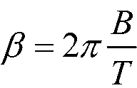
마스터(M)로부터의 RF 신호는, 마스터와 태그 사이의 다중경로 현상을 기초로 하는 위상 편이(![]()
![]()
![]()
![]()
![]()
![]()
![]()
![]()
AM(트랜스폰더) 수신기에서, 제 1 다운 컨버터(down converter)(요소(85))의 출력(가령, 제 1 IF)에서, 신호의 위상은 다음의 수학식을 따른다:In an AM transponder receiver, at the output of a first down converter (element 85) (e.g., the first IF), the phase of the signal follows the formula:

수신기의 RF 섹션(요소(15 및 60-85))에서 전파 딜레이 ![]()
![]()

FPGA(150)에서, (ADC 출력으로부터의) 제 2 IF 신호가 RF 백-엔드 디지털 필터(190)에 의해 필터링되고, 제 3 다운-컨버터(즉, 직교위상 믹서(200), 디지털 필터(230 및 210), 디지털 직교위상 오실레이터(220))에 의해 추가로 기저대역 레인징 신호로 다시 하향-변환(down-convert)되고, 합산기(270)에서 합산되어, 메모리(170)에 저장된다. 제 3 다운-컨버터의 출력단(즉, 직교위상 믹서)에서 다음과 같다:In the

FIR 섹션(190)에서 전파 딜레이![]()
![]()
RX->TX 딜레이 후, (메모리(170)에) 저장된 마스터(M)로부터의 기저대역 레인징 신호가 재전송된다. RX->TX 딜레이 ![]()
![]()
트랜스폰더로부터의 신호가 마스터(M)의 수신기 안테나에 도달하는 시간에 의해, 트랜스폰더(AM)로부터의 RF 신호는, 다중 경로의 함수인 또 다른 위상 편이(![]()
![]()

마스터 수신기에서, 트랜스폰더로부터의 신호는, 트랜스폰더 수신기에서와 동일한 하향 변환 프로세스를 겪는다. 결과물은 복원된 기저대역 레인징 신호(마스터가 본래 전송했던 신호)이다. At the master receiver, the signal from the transponder undergoes the same down conversion process as at the transponder receiver. The result is a reconstructed baseband ranging signal (the signal that the master originally transmitted).
제 1 주파수 성분 F1에 대하여:For the first frequency component F 1 :

제 2 주파수 성분 F2에 대하여: For the second frequency component F 2 :

치환:substitution:
![]()
![]()
이때, ![]()
![]()

이때, ![]()
![]()
또한, ![]()
![]()
제 1 주파수 성분 F1:First frequency component F 1 :

계속해서, 제 1 주파수 성분 F1:Subsequently, the first frequency component F 1 :
제 2 주파수 성분 F2:Second frequency component F 2 :

계속해서, 제 2 주파수 성분 F2:Subsequently, the second frequency component F 2 :
추가로 치환하면:Further substitution:

이때, ![]()
![]()
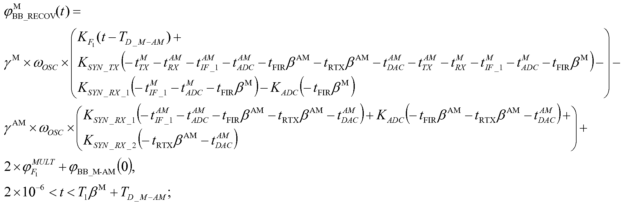
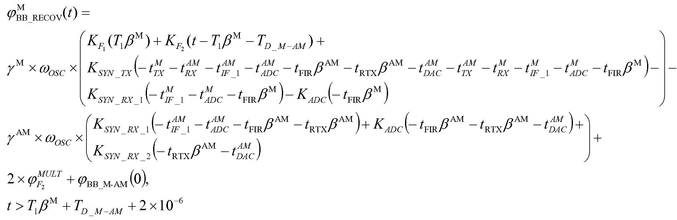
그 후, 최종적인 위상 수식이 수학식 5와 같다. Then, the final phase equation is as shown in Equation (5).
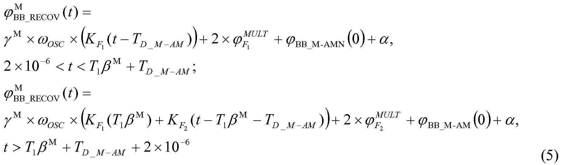
상기 수학식 5에서:In the above equation (5)

이때, i=2, 3, 4, ............이고, ![]()
![]()
![]()
![]()
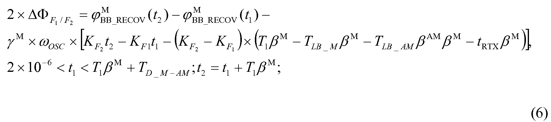
예를 들어, 시간 t1과 t2에서의 차이 ![]()
![]()

![]()
![]()
![]()
![]()

이때, ![]()
![]()
![]()
![]()
![]()
![]()
![]()
![]()
![]()
![]()
앞의 수학식들과 ![]()
![]()
![]()
![]()
![]()
![]()

또는, ![]()
![]()
[수학식 6a][Equation 6a]

수학식 6으로부터, 동작 주파수에서의 레인징 신호의 복소 진폭 값이 반환된 기저대역 레인징 신호를 처리하는 것으로부터 밝혀질 수 있다.From Equation (6), it can be seen that the complex amplitude value of the ranging signal at the operating frequency processes the returned baseband ranging signal.
부분공간 알고리즘이 정위상 오프셋(constant phase offset)에 민감하지 않기 때문에, 초기 위상 값 ![]()
![]()
![]()
![]()
![]()
![]()
![]()
![]()
![]()
![]()
![]()
![]()
바람직한 실시예에서, 다중경로 프로세서의 아크탄젠트 블록(250)에 의해, 반환된 기저대역 레인징 신호의 위상 값 ![]()
![]()
![]()
![]()
![]()
![]()
수학식 5 및 6으로부터, 복원된(즉, 수신된) 기저대역 레인징 신호는, 마스터에 의해 전송되었던 원본 기저대역 신호와 동일한 주파수를 가진다. 따라서 마스터(M)와 트랜스폰더(AM)의 시스템 클록이 서로 상이할 수 있다는 사실에도 불구하고, 어떠한 주파수 변환(frequency translation)도 없다. 기저대역 신호는 몇 가지 주파수 성분으로 구성되며, 각각의 성분은 정현파의 복수의 주기로 구성되기 때문에, 원본(즉, 마스터에 의해 전송된) 기저대역 신호의 개별 주파수 성분으로, 상기 원본에 대응하는 수신된 기저대역 신호의 개별 성분 주파수를 샘플링하고, 주기 ![]()
![]()
이러한 작업은, 수신된 레인징 신호의 복소 진폭 값 ![]()
![]()
![]()
![]()
![]()
![]()
![]()
![]()
샘플링하는 과정과, ![]()
![]()
![]()
![]()
![]()
![]()
레인징 신호의 대역폭이 협대역이지만, 주파수 차이(![]()
![]()
![]()
![]()
바람직한 실시예에서, 단 2개의 협대역 디지털 필터만 사용되는데, 하나는 항상 ![]()
![]()
![]()
![]()
![]()
![]()
주파수 합성기(frequency synthesizer)를 조정함으로써(가령, ![]()
![]()
앞의 수학식에서 사용되는 실제 ![]()
![]()
![]()
![]()
![]()
![]()
![]()
![]()
![]()
![]()
![]()
![]()
![]()
![]()
![]()
![]()
위상 추정 에러(수학식 7)가 정확도에 영향을 미친다. 따라서 이러한 에러를 최소화할 필요가 있다. ![]()
![]()
![]()
![]()
바람직한 실시예에서, 마스터와 트랜스폰더 유닛(장치)은, 임의의 장치와 클럭을 동기화시킬 수 있다. 예를 들어, 마스터 장치가 기준으로서 기능할 수 있다. 원격 제어 통신 채널을 이용함으로써, 클럭 동기화가 이뤄지고, 이로 인해, FPGA(150) 제어 하에서, 온도 보상형 수정 발진기(TCXO)(20)의 주파수가 조정된다. 선택된 트랜스폰더 장치가 반송파 신호(carrier signal)를 송신하는 동안, 마스터 장치의 합산기(270)의 출력에서 주파수 차이가 측정된다. In a preferred embodiment, the master and transponder unit (device) can synchronize the clock with any device. For example, a master device may function as a reference. By using the remote control communication channel, clock synchronization is achieved, and under this control of the
그 후, 마스터는 트랜스폰더에게 TCXO의 주파수를 증가/감소시키라는 명령어(command)를 전송한다. 이 절차는 여러 번 반복되어, 합산기(270)의 출력에서의 주파수를 최소화시킴으로써, 더 정확한 주파수가 얻어질 수 있다. 이상적인 경우에서, 합산기(270) 출력에서의 주파수는 0이 되어야 한다. 대안적 방법으로는, 주파수 차이를 측정하고, 트랜스폰더의 TCXO 주파수를 조정하지 않고 추정된 위상을 교정하는 것이 있다. The master then sends a command to the transponder to increase / decrease the frequency of the TCXO. This procedure is repeated a number of times so that a more accurate frequency can be obtained by minimizing the frequency at the output of the
![]()
![]()
![]()
![]()
상용화된(기성품인) TCXO 구성요소는 높은 정확도와 안정성을 가진다. 특히 GPS의 상업적 적용예를 위한 TCXO 구성요소는 매우 정확하다. 이들 장치를 이용하여, 빈번한 클럭 동기화가 필요 없이, 위치 찾기 정확도에 영향을 미치는 위상 오류가 1미터 이하가 될 수 있다. Commercial (ready-made) TCXO components have high accuracy and stability. Especially the TCXO component for commercial applications of GPS is very accurate. With these devices, there is no need for frequent clock synchronization, and phase errors that affect positioning accuracy can be less than 1 meter.
협대역 레인징 신호 다중경로 완화 프로세서가 반환된 협대역 레인징 신호 복소 진폭 ![]()
![]()
슈퍼-분해능 알고리즘은 ![]()
![]()
![]()
![]()
![]()
![]()
레인징 신호의 협대역 요구치가 다소 완화되는 특정 경우에서, (시간적으로) 연속인 처프(chirp)를 이용함으로써, DLOS 경로가 MP 경로로부터 분리될 수 있다. 바람직한 실시예에서, 이러한 연속 처프는 선형 주파수 변조(LFM: Linear Frequency Modulation)이다. 그러나 그 밖의 다른 처프 파형도 사용될 수 있다. In certain cases where the narrowband requirement of the ranging signal is somewhat mitigated, the DLOS path can be separated from the MP path by using a chirp that is continuous (temporally). In a preferred embodiment, this continuous chirp is linear frequency modulation (LFM). However, other chirp waveforms may be used.
다중경로 완화 프로세서 제어 하에서, 대역폭 ![]()
![]()
![]()
![]()
다중경로 프로세서에서, 반환된 처프가 관심 영역의 중심부로부터 오도록 각각 수신된 단일 처프가 정렬된다.In a multipath processor, each received chirp is aligned such that the returned chirp is from the center of the region of interest.
처프 파형 수학식은, The chirp wave formulas,
![]()
![]()
![]()
![]()
![]()
![]()
단일 딜레이 왕복 ![]()
![]()
![]()
![]()
그 후, 다중경로 완화 프로세서가, 송신된 원본 처프와의 복소 켤레 혼합을 수행함으로써, ![]()
![]()
![]()
![]()
여기서, ![]()
![]()
![]()
![]()
![]()
![]()
다중경로의 경우, 복합 디램프된 신호(composite deramped signal)는, 다음의 수학식 9와 같이 복수의 복소 정현파형이다: In the case of multipath, the composite deramped signal is of a plurality of complex sinusoidal forms as: < RTI ID = 0.0 >

이때, L은 DLOS 경로를 포함한 레인징 신호 경로의 개수이며, ![]()
![]()
복수의 처프가 송신되고 처리된다. 각각의 처프는 개별적으로, 앞서 언급된 방식대로 취급/처리된다. 그 후, 다중경로 완화 프로세서가 수학식 10에 따라 개별 처프 처리의 결과를 조합(assemble)한다:A plurality of chirps are transmitted and processed. Each chirp is individually handled / handled in the manner previously mentioned. The multipath mitigation processor then assemble the results of the individual chirp processing according to equation (10): < EMI ID =
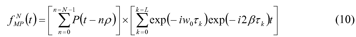
이때, N은 처프의 개수이며, 
![]()
![]()
![]()
![]()
![]()
![]()
수학식 10에서, ![]()
![]()
![]()
![]()
따라서 샘플의 개수는 N의 배수일 수 있다. 가령, ![]()
![]()
수학식 10으로부터, 다중경로 완화 프로세서가, 추가 프로세싱(즉, 슈퍼-분해능 알고리즘의 실행)에서 사용되는 시간 영역에서 ![]()
![]()
슈퍼-분해능 알고리즘이 ![]()
![]()
![]()
![]()
![]()
![]()
슈퍼-분해능 알고리즘의 대안이 되는 "임계 기법(threshold technique)"이라고 일컬어지는 특수 프로세싱 방법에 대한 설명이 제공될 예정이다. 즉, 인공적으로 생성된 합성 광대역 레인징 신호를 이용하여 DLOS 경로를 다른 MP 경로와 구별할 때 신뢰도와 정확도를 증가시키기 위해 사용된다. A description of the special processing method, referred to as the " threshold technique ", which is an alternative to the super-resolution algorithm, will be provided. That is, it is used to increase the reliability and accuracy when distinguishing the DLOS path from other MP paths using an artificially generated synthetic wideband ranging signal.
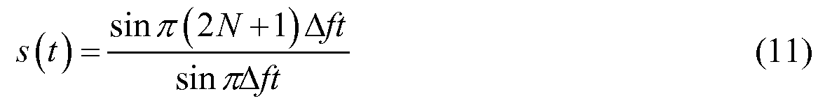
다음의 수학식 11에 따라, 도 1 및 도 1A에 나타난 주파수 영역 기반-대역 레인징 신호가 시간 영역 기반-대역 신호 ![]()
![]()
![]()
![]()
![]()
![]()
![]()
![]()
도 4는 N=11이고, ![]()
![]()
![]()
![]()
![]()
![]()
![]()
![]()
바람직한 실시예에서 사용되는 임계 방법의 기본 아이디어는, DLOS 경로를 MP 경로로부터 구별할 때 인공적으로 발생된 합성 광대역 레인징의 신뢰도와 정확도를 높이는 것이다. 상기 임계 방법은 광대역 펄스의 앞 가장자리(leading edge)의 시작점이 수신기에 도달할 때를 검출한다. 송신기와 수신기에서의 필터링 때문에, 상기 앞 가장자리는 순간적으로 상승(rise)하는 것이 아니라, 매끄럽게 증가하는 경사를 갖고 노이즈없이 상승한다. 앞 가장자리가 지정 임계값 ![]()
![]()
작은 임계값은 더 빨리 교차되고, 펄스의 시작 시각과 임계값 교차 시각 간의 에러 딜레이 ![]()
![]()
![]()
![]()
![]()
![]()
![]()
![]()
도 4에 도시된 2.75㎒ 폭의 신호가 꽤 넓은 대역폭을 가질지라도, 앞서 언급된 방법에 의해 거리(range)를 측정하는 것이 적합하지 않다. 상기 방법은 각각의 송신된 펄스가 0-신호 프리커서(zero-signal precursor)를 가질 것을 요구한다. 그러나 펄스들 사이에 정현파형이 실질적으로 상쇄되도록 신호를 수정함으로써 이러한 목표를 이루는 것이 가능하다. 바람직한 실시예에서, 이는, 높은(tall) 펄스들 간 선택된 구간에서 신호에 근사하는 파형을 구축하고, 원본 신호에서 이를 뺌으로써, 이뤄진다. Although the 2.75 MHz wide signal shown in FIG. 4 has a fairly wide bandwidth, it is not suitable to measure the range by the above-mentioned method. The method requires each transmitted pulse to have a zero-signal precursor. However, it is possible to achieve this goal by modifying the signal so that the sinusoidal waveform between the pulses is substantially canceled. In a preferred embodiment, this is accomplished by building a waveform that approximates the signal at selected intervals between high (tall) pulses and subtracting it from the original signal.
상기 기법은 도 1의 신호에 대입하여 설명될 수 있다. 파형 상에 보이는 2개의 검은 점은, 처음 2개의 펄스들 사이에서 중앙에 위치하는 구간 I의 종단점들이다. 구간 I의 좌 종단점과 우 종단점은, 최상의 결과를 제공하기 위해 실험적으로 결정되었으며, 각각 다음의 수학식 12에 따른다:The above technique can be explained by substituting into the signal of FIG. The two black dots on the waveform are the end points of the interval I centered between the first two pulses. The left and right endpoints of interval I have been experimentally determined to provide the best results, and are each according to: < RTI ID = 0.0 >

이 구간에서 신호 ![]()
![]()
![]()
![]()
![]()
![]()
![]()
![]()
![]()
![]()
![]()
![]()
![]()
![]()
![]()
![]()

![]()
![]()

이때, At this time,
![]()
![]()
그리고, 계수 ![]()
![]()

![]()
![]()
![]()
![]()
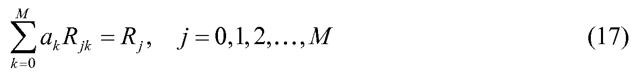
상기 수학식 17은 ![]()
![]()

이다. to be.
그 후, After that,
수학식 12에 의해 제공되는 함수 ![]()
![]()

![]()
![]()
![]()
![]()
![]()
![]()
![]()
![]()
![]()
![]()

여기서, here,

수학식 17로부터, 희망 신호![]()
![]()
![]()
![]()
![]()
![]()
![]()
![]()
![]()
![]()
앞서 언급된 ![]()
![]()
1. 수학식 14에서 나타나는 바와 같이, 최저 주파수는 0㎐이며, 최고 주파수는 ![]()
![]()
![]()
![]()
2. 주파수 ![]()
![]()
![]()
![]()
3. 원본 신호 ![]()
![]()
![]()
![]()
![]()
![]()
![]()
![]()
![]()
![]()
![]()
![]()
![]()
![]()
![]()
![]()
이는 소거 함수 ![]()
![]()
![]()
![]()
![]()
![]()
![]()
![]()
![]()
![]()
![]()
![]()
![]()
![]()
4. ![]()
![]()
![]()
![]()
![]()
![]()
![]()
![]()
5. ![]()
![]()
![]()
![]()
![]()
![]()
6. 다음의 (a)및 (b)를 이용하여, 큰 프로세싱 이득이 얻어진다: (a) ![]()
![]()
![]()
![]()
![]()
![]()
도 5에서 도시된 신호 ![]()
![]()
![]()
![]()
![]()
![]()
![]()
![]()
더 적은 개수의 반송파를 이용하는 것이 도 6에 도시되어 있으며, 여기서 단지 총 2N+3=0개의 반송파에 대해![]()
![]()
![]()
![]()
![]()
![]()
![]()
![]()
그러나 더 적은 개수의 반송파가 사용되기 때문에, 메인 피크의 진폭은 예상되는 가외() 프로세싱 이득을 소거하도록 의도된 이전 것의 약 1/3배이다. 또한, 0-신호 프리커서 세그먼트의 길이가, 약 0.8마이크로초 또는 240미터로 더 짧아진다. 이는 다중경로로 인한 ![]()
![]()
![]()
![]()
RF 주파수에서의 송신: 지금까지 간단 명료성을 위해 ![]()
![]()
![]()
![]()
![]()
![]()
![]()
![]()
![]()
![]()
![]()
![]()
![]()
![]()
![]()
![]()
![]()
![]()
![]()
![]()
송신기와 수신기는 주파수 동기화된다고 가정된다. 매개변수 ![]()
![]()
![]()
![]()
![]()
![]()
![]()
![]()
![]()
![]()
![]()
![]()
![]()
![]()
도 1과 도 1A에서 순차 반송파 송신(sequential carrier transmission) 및 신호 재구성(signal reconstruction)이 도시된다. 송신기와 수신기는 시간 동기 및 주파수 동기된다고 가정되며, 2N+3개의 송신되는 반송파는 동시에 송신될 필요는 없다고 가정된다. 예를 들어, 도 1A 및 도 6에 도시된 기저대역 표현을 갖는 신호의 송신을 가정하자. Sequential carrier transmission and signal reconstruction are shown in FIGS. 1 and 1A. It is assumed that the transmitter and the receiver are assumed to be time synchronous and frequency synchronized, and that 2N + 3 transmitted carriers need not be transmitted simultaneously. For example, assume the transmission of a signal having the baseband representation shown in Figs. 1A and 6.
도 6에서, N=3이고, 9개의 주파수 성분 각각이 1밀리초(millisecond) 동안 순차적으로 송신된다고 가정하자. 각각의 주파수 송신에 대한 시작 시각과 종료 시각이 수신기에 알려짐으로써, 수신기는 각각의 주파수 성분의 수신을 각각의 수신 시각에서 시작하고 종료할 수 있다. 신호 전파 시간은 1밀리초에 비교할 때 매우 짧기 때문에(의도된 적용예에서 수 마이크로초보다 짧은 것이 일반적일 것), 각각의 수신된 주파수 성분의 작은 부분은 무시되어야 하며, 수신기는 이를 손쉽게 지울 수 있다. In FIG. 6, assume that N = 3, and each of the nine frequency components is sequentially transmitted for 1 millisecond. The start and end times for each frequency transmission are known to the receiver so that the receiver can start and end the reception of each frequency component at each reception time. Since the signal propagation time is very short compared to one millisecond (it is common to be fewer than a few microseconds in the intended application), a small portion of each received frequency component should be ignored and the receiver can easily erase it have.
프로세싱 이득을 증가시키기 위해, 9개의 주파수 성분을 수신하는 전체 프로세스는 추가 수신의 9-밀리초 블록에서 반복될 수 있다. 총 수신 시간의 절반 동안, 프로세싱 이득을 위해 이용 가능한 이러한 9-밀리초 블록이 약 111개 존재하 것이다. 덧붙여, 각각의 블록 내에서, ![]()
![]()
일반적으로 신호 재구성은 매우 경제적으로 이뤄질 수 있으며, 본질적으로 모든 가능한 프로세싱 이득을 가능하게 할 것이라는 점을 주목할 만하다. 2N+3개의 수신된 주파수 각각에 대하여: 1. 상기 각각의 주파수의 각각의 1-밀리초 수신의 위상과 진폭을 측정하여, 상기 주파수에 대응하는 저장된 벡터(페이서(phasor))의 시퀀스를 형성하고, 2. 상기 각각의 주파수에 대해 저장된 벡터의 평균을 구하며, 3. 마지막으로, 2N+3개의 주파수에 대해 2N+3개의 벡터 평균 값을 이용하여, 지속시간 ![]()
![]()
이 방법은 1-밀리초 송신으로 제한되는 것은 아니며, 송신의 길이는 이보다 길거나 짧을 수 있다. 그러나 모든 송신에 대한 총 시간은, 수신기 또는 송신기의 어떠한 동작도 동결(freeze)시키기에 충분할 정도로 짧아야 한다. This method is not limited to 1-millisecond transmissions, and the length of the transmission may be longer or shorter. However, the total time for all transmissions should be short enough to freeze any operation of the receiver or transmitter.
![]()
![]()
![]()
![]()
![]()
![]()
![]()
![]()
![]()
![]()
![]()
![]()
![]()
![]()
수신기에서의 계수 가중: 바람직하다면, 수학식 21에서 계수 ![]()
![]()
![]()
![]()
![]()
![]()
![]()
![]()
![]()
![]()
![]()
![]()
![]()
![]()
![]()
![]()
![]()
![]()
![]()
![]()
![]()
![]()
그 후 송신기가 모든 주파수를 동일한 진폭을 갖고 송신할 수 있으며, 이는 설계를 간단하게 해준다. 이 방법은 또한 각각의 주파수에서의 노이즈로 가중하며, 이로 인한 영향도 고려해야 한다. 이용가능한 메인 피크의 2배를 얻기 위해 ![]()
![]()
채널에서 중앙 주파수로의 ![]()
![]()
![]()
![]()
![]()
![]()
![]()
![]()
거리 측정 기능을 수행하는 것에 추가로 이뤄지는, 임의의 무선 주파수(RF)-기반의 식별, 추적 및 위치 찾기 시스템에 있어서, 마스터 유닛과 태그 유닛 모두, 음성, 데이터 및 제어 통신 기능도 수행한다. 마찬가지로, 바람직한 실시예에서, 마스터 유닛과 태그 유닛 모두, 거리 측정 기능에 추가로, 음성, 데이터 및 제어 통신 기능을 수행한다. In any radio frequency (RF) -based identification, tracking and locating system, in addition to performing a distance measurement function, both the master unit and the tag unit also perform voice, data and control communication functions. Likewise, in the preferred embodiment, both the master unit and the tag unit perform voice, data and control communication functions in addition to the distance measurement function.
바람직한 실시예에서, 하나 이상의 레인징 신호가, 다중경로 완화를 포함하여 광범위한 정교한 신호 프로세싱 기법의 대상이 된다. 그러나 이들 기법은 음성, 데이터 제어 신호에 적합하지 않을 수 있다. 따라서, 제안된 시스템(및 그 밖의 다른 기존 시스템)의 동작 범위는, 상기 시스템의 거리를 신뢰할만하고 정확하게 측정하는 기능에 의해서가 아니라, 음성 및/또는 데이터 및/또는 제어 통신 동안 범위를 벗어나는 것에 의해, 제한될 수 있다. In a preferred embodiment, one or more ranging signals are subject to a wide range of sophisticated signal processing techniques, including multipath mitigation. However, these techniques may not be suitable for voice and data control signals. Thus, the range of motion of the proposed system (and other existing systems) is not limited by the ability to reliably and accurately measure the distance of the system, but rather to the extent that it is out of range during voice and / or data and / , ≪ / RTI >
그 밖의 다른 무선 주파수(RF)-기반 식별, 추적 및 위치찾기 시스템에서, 거리 측정 기능이 음성, 데이터 및 제어 통신 기능과 분리된다. 이 실시예에서, 별도의 RF 트랜시버가 음성, 데이터 및 제어 통신 기능을 수행하기 위해 사용된다. 이러한 접근법의 단점은 시스템의 증가되는 비용, 복잡도, 크기 등이다. In other radio frequency (RF) -based identification, tracking and location systems, the distance measurement function is separated from the voice, data and control communication functions. In this embodiment, a separate RF transceiver is used to perform voice, data, and control communications functions. A disadvantage of this approach is the increased cost, complexity, and size of the system.
앞서 언급된 단점을 피하기 위해, 바람직한 실시예에서, 협대역 레인징 신호, 또는 기저대역 협대역 레인징 신호의 복수 개의 개별 주파수 성분이, 동일한 데이터/제어 신호를 이용해 변조되고, 음성의 경우, 디지털화된 음성 패킷 데이터로 변조된다. "보팅(voting)", 또는 그 밖의 다른 정보 가외성(information redundancy)을 이용하는 신호 프로세싱 기법을 수행함으로써, 수신기에서, 가장 높은 신호 강도를 갖는 개별 주파수 성분이 복조되고, 획득된 정보 신뢰도가 추가로 강화될 수 있다. In order to avoid the aforementioned disadvantages, in a preferred embodiment, a plurality of discrete frequency components of a narrowband ranging signal, or a baseband narrowband ranging signal, are modulated using the same data / control signal, And is then modulated into voice packet data. By performing signal processing techniques that utilize "voting" or other information redundancy, at the receiver, individual frequency components with the highest signal strength are demodulated, and the obtained information reliability is further enhanced .
이 방법에 의해, 다중 경로로부터의 유입 RF 신호가 DLOS 경로와, 그리고 서로 서로 파괴적으로(destructively) 결합하여, 수신된 신호 강도 및 이와 연계된 SNR을 상당히 감소시키는 "널(null)" 현상이 피해질 수 있다. 덧붙여, 이러한 방법에 의해, 다중 경로로부터의 유입 신호가 DLOS 경로와, 그리고 서로 서로 건설적으로(constructively) 결합하여, 수신된 신호 강도 및 이와 연계된 SNR이 증가하는, 주파수 세트가 발견될 수 있다. With this method, the incoming RF signals from the multipaths destructively combine with the DLOS path and with each other, thereby avoiding "null" phenomena that significantly reduce the received signal strength and associated SNR Can be. In addition, with this method, a set of frequencies can be found in which the incoming signals from the multipaths constructively combine with the DLOS path and with each other, such that the received signal strength and the associated SNR increase.
앞서 언급된 바와 같이, 스펙트럼 추정치-기반 슈퍼-분해능 알고리즘은 동일한 모델(즉, 주파수의 복소 지수 함수 및 이들의 복소 진폭의 선형 조합)을 이용하는 것이 일반적이다. 이러한 복소 진폭은 수학식 3에 의해 제공된다. As noted above, it is common for the spectral estimate-based super-resolution algorithms to use the same model (i.e., a linear exponential function of the frequency and a linear combination of their complex amplitudes). This complex amplitude is provided by Equation (3).
모든 스펙트럼 추정-기반 슈퍼-분해능 알고리즘은, 복소 지수 함수의 개수, 즉, 다중경로의 개수에 대한 선험적 지식을 필요로 한다. 이러한 복소 지수 함수의 개수는 모델 크기라고 지칭되며, 수학식 1-3에서 나타난 것과 같이, 다중경로 성분 L의 개수로 결정된다. 그러나 RF 추적-위치찾기 적용예의 경우 경로 딜레이를 추정할 때, 이러한 정보는 이용 가능하지 않다. 이는 또 다른 크기, 즉, 모델 크기 추정치를, 슈퍼-분해능 알고리즘을 통해 스펙트럼 추정 프로세스에 추가한다. All spectral estimation-based super-resolution algorithms require a priori knowledge of the number of complex exponential functions, i. E., The number of multipaths. The number of such complex exponential functions is referred to as the model size and is determined by the number of multipath components L, as shown in Equations 1-3. However, in the case of the RF tracking-location application, this information is not available when estimating path delays. This adds another size, i.e., the model size estimate, to the spectral estimation process via a super-resolution algorithm.
모델 크기의 과소추정(underestimation)의 경우 주파수 추정치의 정확도가 중요하며 모델 크기가 과대추정된 경우 알고리즘은 스푸리어스(spurious), 즉, 존재하지 않는 주파수를 발생한다고 알려져 있다(Kei Sakaguchi 외 다수, Influence of the Model Order Estimation Error in the ESPRIT Based High Resolution Techniques 참조). 모델 크기 추정을 위한 기존의 방법, 가령, AIC(Akaikes Information Criterion), MDL(Minimum Description Length) 등은 신호들(복소 지수 함수) 간의 상관관계(correlation)에 대한 높은 민감도를 가진다. 그러나 RF 다중경로의 경우, 이는 항상 해당된다. 심지어, 순방향-역방향 스무딩 알고리즘(Forward-Backward smoothing algorithm)이 적용된 후, 항상 잔존 상관관계가 존재할 것이다. In case of underestimation of the model size, the accuracy of the frequency estimate is important. If the model size is overestimated, the algorithm is known to generate spurious, ie, nonexistent frequencies (Kei Sakaguchi et al. Influence of the Model Order Estimation Error in the ESPRIT Based High Resolution Techniques. Conventional methods for model size estimation, such as Akaikes Information Criterion (AIC) and Minimum Description Length (MDL), have a high sensitivity to correlation between signals (complex exponential functions). However, in the case of RF multipath, this is always the case. Even after a forward-backward smoothing algorithm is applied, there will always be a residual correlation.
Sakaguchi의 논문에서, 이들 신호 파워(진폭)를 추정하고, 매우 낮은 파워를 갖는 신호를 거절함으로써, 스푸리어스 주파수(신호)로부터 과대추정된 모델 및 차별화된 실제 주파수(신호)를 이용하는 것이 제안되었다. 이 방법이 기존 방법에 비해 개선된 것이지만, 보장되지는 않는다. 본 발명의 발명자는 Kei Sakaguchi 외 다수의 방법을 구현했고, 더 큰 모델 크기의 더 복잡한 경우에 대해 시뮬레이션을 구동했었다. 일부 경우에서, 스푸리어스 신호가 실제 신호 진폭에 매우 가까운 진폭을 가질 수 있음이 관찰되었다. In Sakaguchi's paper, it has been proposed to use these overestimated models and differentiated actual frequencies (signals) from spurious frequencies (signals) by estimating these signal powers (amplitudes) and rejecting signals with very low powers . Although this method is improved compared to the existing method, it is not guaranteed. The inventor of the present invention implements Kei Sakaguchi et al.'S method and has driven the simulation for more complex cases of larger model sizes. In some cases it has been observed that the spurious signal can have an amplitude very close to the actual signal amplitude.
모든 스펙트럼 추정-기반 슈터-분해능 알고리즘은, 유입 신호 복소 진폭 데이터를 2개의 부분 공간(즉, 노이즈 부분공간과 신호 부분공간)으로 나눔으로써, 기능한다. 부분공간이 적정하게 형성(서로 분리)된 경우, 모델 크기는 신호 부분공간 크기와 동일하다.All spectral estimation-based shooter-resolution algorithms function by dividing the incoming signal complex amplitude data into two subspaces (i.e., noise subspaces and signal subspaces). When the subspaces are properly formed (separated from each other), the model size is the same as the signal subspace size.
본 발명의 하나의 실시예에서, 모델 크기 추정은 "F" 통계치를 이용하여 이뤄진다. 예를 들어, ESPRIT 알고리즘에 있어서, (순방향/역방향 상관 스무딩을 이용한) 공분산 행렬의 추정의 특이 값 분해(singular value decomposition)가 오름차순으로 정렬된다. 그 후, (n+1)개의 고유값(eigenvalue)이 n번째 고유값에 의해 나눠지는분할이 이뤄진다. 이러한 비는 "F" 랜덤 변수이다. 최악의 경우(worst case)는 (1,1) 자유도의 "F" 랜덤 변수이다. (1,1) 자유도를 갖는 "F" 랜덤 변수에 대한 95% 신뢰 구간은 161이다. 상기 값을 임계치로서 설정함으로써, 모델 크기가 결정된다. 노이즈 부분공간에 있어서, 고유 값은 노이즈 파워의 추정치를 나타낸다. In one embodiment of the present invention, model size estimation is accomplished using "F" statistics. For example, in the ESPRIT algorithm, the singular value decomposition of the estimate of the covariance matrix (using forward / backward correlation smoothing) is sorted in ascending order. Thereafter, division is performed in which (n + 1) eigenvalues are divided by the n-th eigenvalue. This ratio is the "F" random variable. The worst case is the random variable "F" of (1, 1) degrees of freedom. The 95% confidence interval for the "F" random variable with (1,1) degrees of freedom is 161. By setting the value as a threshold value, the model size is determined. In the noise subspace, the eigenvalue represents an estimate of the noise power.
"F" 통계치를 고유 값들의 비에 적용하는 이러한 방법은 모델 크기를 추정하는 더 정확한 방법이다. "F" 통계치에서 그 밖의 다른 자유도가 임계치 계산을 위해, 그리고 결과적으로는 모델 크기 추정을 위해 사용될 수 있다. This method of applying the "F" statistic to the ratio of eigenvalues is a more accurate method of estimating the model size. Other degrees of freedom in the "F" statistics can be used for threshold calculation, and consequently for model size estimation.
그럼에도 불구하고, 일부 경우, 실세계 측정의 결함 때문에, 둘 이상의 (시간상으로) 매우 가까이 이격된 신호들이 하나의 신호로 변질될 수 있다. 따라서 앞서 언급된 방법은 신호의 개수, 즉 모델 크기를 과소추정할 것이다. 모델 크기의 과소추정은 주파수 추정치의 정확도를 감소시키기 때문에, 특정 개수를 추가함으로써, 모델 크기를 증가시키는 것 바람직하다. 이러한 개수는 실험적으로 및/또는 시뮬레이션을 통해 결정될 수 있다 그러나 신호가 너무 가까이 위치하는 것이 아닐 때, 모델 크기는 과대추정될 것이다. Nevertheless, in some cases, due to a defect in real-world measurements, signals that are separated by more than one (in time) can be transformed into a single signal. Therefore, the above-mentioned method will underestimate the number of signals, that is, the size of the model. Since underestimation of the model size reduces the accuracy of the frequency estimate, it is desirable to increase the model size by adding a specific number. This number can be determined experimentally and / or through simulation. However, when the signal is not located too close, the model size will be overestimated.
이러한 경우, 스푸리어스, 즉, 존재하지 않는 주파수가 나타날 수 있다. 앞서 언급한 바와 같이, 스푸리어스 신호 검출을 위해 신호 진폭을 이용하는 것이 항상, 효과가 있는 것은 아니다. 왜냐하면 일부 경우 스푸리어스 신호가 실제 신호 진폭과 매우 유사한 진폭을 갖는다고 관측되었기 때문이다. 따라서 진폭 감별에 추가로, 스푸리어스 주파수 제거 확률을 개선하기 위한 필터가 구현될 수 있다. In this case, a spurious, i.e., non-existent frequency may appear. As mentioned earlier, it is not always effective to use the signal amplitude for spurious signal detection. This is because in some cases it has been observed that the spurious signal has an amplitude very similar to the actual signal amplitude. Thus, in addition to amplitude discrimination, a filter may be implemented to improve the spurious frequency rejection probability.
슈퍼-분해능 알고리즘에 의해 추정된 주파수는 인공 주파수(artificial frequency)(수학식 2)이다. 실제로, 이들 주파수는 다중경로 환경의 개별 경로 딜레이이다. 따라서 어떠한 음의 주파수(negative frequency)도 존재하지 않아야 하고, 슈퍼-분해능 알고리즘에 의해 생성되는 모든 음의 주파수는 거절되어야 할 스푸리어스 주파수이다. The frequency estimated by the super-resolution algorithm is the artificial frequency (Equation 2). In practice, these frequencies are individual path delays in a multipath environment. Therefore, no negative frequency should be present, and all negative frequencies generated by the super-resolution algorithm are spurious frequencies that should be rejected.
덧붙여, 슈퍼 분해능 방법과 상이한 방법을 이용한 측정 동안 복수 진폭 값![]()
![]()
![]()

![]()
![]()
![]()
예시적 실시예에서, 레인징 신호가 왕복(round-trip)한다. 다시 말하자면, 상기 레인징 신호가 양 방향으로(마스터/판독기에서 표적/슬레이브로, 그리고 표적/슬레이브에서 다시 마스터/판독기로) 이동한다는 것이다. In an exemplary embodiment, the ranging signal is round-tripped. In other words, the ranging signal travels in both directions (from the master / reader to the target / slave, and again from the target / slave to the master / reader).
마스터는 톤(tone), ![]()
![]()
![]()
![]()
![]()
![]()
표적의 수신기에서, 수신된 신호(단방향, one way)가 다음 수학식 25에 따른다:At the target's receiver, the received signal (unidirectional) is given by:

이때, N은 다중경로 환경에서의 신호 경로의 개수이며, K0 및 ![]()
![]()
![]()
![]()
![]()
![]()

여기서, ![]()
![]()
![]()
![]()
표적은 수신된 신호를 재송신(retransmit)한다:The target retransmits the received signal:
![]()
![]()
마스터 수신기에서, 왕복(round-trip) 신호는 수학식 28과 같다:At the master receiver, the round-trip signal is: < RTI ID = 0.0 >

다른 한편으로는 수학식 26 및 28으로부터 수학식 29가 도출된다: On the other hand, Equation 29 is derived from Equations 26 and 28: < RTI ID = 0.0 >
이때, 
수학식 29에 따르면, 왕복 다중경로 채널은, 단방향 채널 다중경로보다 더 많은 개수의 경로를 가진다. 왜냐하면, ![]()

![]()
![]()
![]()
![]()
![]()
이들 조합은 신호(복소 지수 함수)의 개수를 크게 증가시킨다. 따라서 (시간상으로) 매우 가까이 이격되어 있는 신호들의 출현 확률도 증가할 것이고, 이는 유의미한 모델 크기 과소추정을 초래할 수 있다. 따라서 단방향 다중경로 RF 채널전달 함수를 획득하는 것이 바람직하다. These combinations greatly increase the number of signals (complex exponential functions). Thus, the likelihood of appearance of signals that are very closely spaced (in time) will increase, which may result in significant model size and underestimation. It is therefore desirable to obtain a unidirectional multipath RF channel transfer function.
바람직한 실시예에서, 표적/슬레이브 장치로부터 단방향 진폭 값![]()
![]()
![]()
![]()

그러나 ![]()
![]()
![]()
![]()
![]()
![]()
이러한 모호함을 해결하는 것에 대한 자세한 설명이 이하에서 제공된다. 레인징 신호의 서로 다른 주파수 성분이 서로 유사한 경우, 대부분에 있어서, 왕복 위상을 2로 나눔으로써, 단방향 위상이 밝혀질 수 있다. 예외는, "널(null)"에 가까운 영역일 것이며, 여기서 위상은 작은 주파수 스텝에도 상당한 변화를 겪을 수 있기 때문이다. 주의할 것은, "널" 현상은, 복수 위상으로부터의 유입 RF 신호가 DLOS 경로와, 그리고 서로서로 파괴적으로 조합되는 곳에서 발생하고, 따라서 수신된 신호 강도와 이와 연계된 SNR을 상당히 감소시킨다는 점이다. A detailed description of resolving this ambiguity is provided below. When the frequency components of the ranging signal are similar to each other, in most cases, by dividing the reciprocating phase by 2, the unidirectional phase can be revealed. The exception would be a region close to "null ", where the phase may undergo significant changes even at small frequency steps. Note that the "null " phenomenon occurs where the incoming RF signals from multiple phases are combined destructively with the DLOS path and with each other, thus significantly reducing the received signal strength and the associated SNR .
![]()
![]()

이때, ![]()
![]()
![]()
![]()
![]()
![]()
여기서, ![]()
![]()
![]()
![]()
![]()
![]()
![]()
![]()
![]()
![]()
![]()
![]()
![]()
![]()
양방향 전달 함수의 크기가 단방향 크기의 제곱이기 때문에, 다음의 수학식 32가 명백하다:Since the size of the bidirectional transfer function is the square of the unidirectional magnitude, the following equation 32 is evident:
![]()
![]()
그러나, ![]()
![]()
![]()
![]()
![]()
![]()

각각의 서로 다른 주파수 ![]()
![]()
임의의 단방향 전달 함수가 모든 주파수에서 연속이라고 가정하는 다음에 제시되는 정리가 이러한 상황을 해결하는 데 도움이 된다.The following theorem, which assumes that any unidirectional transfer function is continuous at all frequencies, helps to solve this situation.
정리 1: ![]()
![]()
![]()
![]()
![]()
![]()
![]()
![]()
![]()
![]()
![]()
![]()
![]()
![]()
![]()
![]()
![]()
![]()
![]()
![]()
증명: 단방향 전달 함수의 해들 중 하나가, ![]()
![]()
![]()
![]()
![]()
![]()
![]()
![]()
![]()
![]()
![]()
![]()
![]()
![]()
![]()
![]()
![]()
![]()

![]()
![]()
![]()
![]()
![]()
![]()
![]()
![]()
![]()
![]()
![]()
![]()
![]()
![]()
![]()
![]()
![]()
![]()
![]()
![]()
![]()
![]()
![]()
![]()
![]()
![]()
![]()
![]()
![]()
![]()
![]()
![]()
이러한 정리는 전달 함수 ![]()
![]()
![]()
![]()
![]()
![]()
![]()
![]()
![]()
![]()
![]()
![]()
![]()
![]()
단방향 해를 찾기 위한 또 다른 절차가 다음의 정리를 기초로 한다. Another procedure for finding a unidirectional solution is based on the following theorem.
정리 2: ![]()
![]()
![]()
![]()
![]()
![]()
![]()
![]()
![]()
![]()
![]()
![]()
증명: ![]()
![]()
![]()
![]()
![]()
![]()
![]()
![]()
![]()
![]()
![]()
![]()
![]()
![]()
![]()
![]()
![]()
![]()
![]()
![]()
![]()
![]()
![]()
![]()
![]()
![]()
![]()
![]()
![]()
![]()
![]()
![]()
![]()
![]()
![]()
![]()
정리 3: ![]()
![]()
![]()
![]()
![]()
![]()
![]()
![]()
![]()
![]()
![]()
![]()
![]()
![]()
![]()
![]()
![]()
![]()
![]()
![]()
![]()
![]()
![]()
![]()
증명: 이 증명은 정리 1의 증명과 유사하다. 단방향 전달 함수의 해들 중 하나가 함수 ![]()
![]()
![]()
![]()
![]()
![]()
![]()
![]()
![]()
![]()
![]()
![]()
![]()
![]()

가설에 의해, ![]()
![]()
![]()
![]()
![]()
![]()
![]()
![]()
![]()
![]()
![]()
![]()
![]()
![]()
![]()
![]()
![]()
![]()
![]()
![]()
![]()
![]()
![]()
![]()
![]()
![]()
![]()
![]()
![]()
![]()
![]()
![]()
![]()
![]()
![]()
![]()
정리 3은 전달 함수 ![]()
![]()
![]()
![]()
![]()
![]()
![]()
![]()
![]()
![]()
![]()
![]()
![]()
![]()
앞의 정리들이 양방향 함수![]()
![]()
![]()
![]()
![]()
![]()
![]()
![]()
![]()
![]()
![]()
![]()
![]()
![]()
![]()
![]()
![]()
![]()
![]()
![]()
![]()
![]()
![]()
![]()
![]()
![]()
![]()
![]()
![]()
![]()
![]()
![]()
![]()
![]()
![]()
![]()
![]()
![]()
![]()
![]()
![]()
![]()
![]()
![]()
![]()
![]()
![]()
![]()
![]()
![]()
![]()
![]()
처음 2개의 이웃한 개방 부분구간 ![]()
![]()
![]()
![]()
![]()
![]()
![]()
![]()
![]()
![]()
![]()
![]()
![]()
![]()
![]()
![]()
![]()
![]()
![]()
![]()
![]()
![]()
![]()
![]()
![]()
![]()
![]()
![]()
![]()
![]()
![]()
![]()
![]()
![]()
![]()
![]()
![]()
![]()
![]()
![]()
![]()
![]()
![]()
![]()
![]()
![]()
![]()
![]()
![]()
![]()
![]()
![]()
부분구간 ![]()
![]()
![]()
![]()
![]()
![]()
![]()
![]()
![]()
![]()
앞의 재구성 절차에서는, 노이즈가 존재하는 환경에서는 정확하게 계산하기 어렵기 때문에 ![]()
![]()
![]()
![]()
![]()
![]()
실제 구현에서, 양방향 전달 함수 ![]()
![]()
![]()
![]()
RF-기반 거리 측정에 있어서, 선험적으로 알고 있는 형상을 이용하여, 레인징 신호의 서로 가까이 이격되어 있고 겹쳐 있으며 노이즈를 갖는 에코(echo)의 알려지지 않은 개수를 해결하는 것이 필수이다. 주파수 영역에서 레인징 신호가 협대역 신호라고 가정하고, 이러한 RF 현상은 복수의 사인 파들의 합계로서 설명(모델링)될 수 있으며, 이때, 각각의 사인 파는 다중경로 성분당 하나씩이며, 경로의 복소 감쇠 및 전파 딜레이를 가진다. In RF-based distance measurements it is necessary to solve an unknown number of echoes that are closely spaced and overlapping and have noise in the ranging signal using a priori known shape. Assuming that the ranging signal is a narrowband signal in the frequency domain, this RF phenomenon can be described (modeled) as the sum of a plurality of sine waves, where each sine wave is one per multipath component, And a propagation delay.
앞서 언급된 합계의 푸리에 변환을 취함으로써, 이러한 다중경로 모델이 시간 영역으로 표현될 것이다. 이러한 시간 영역 표현식에서 시간 변수와 주파수 변수의 역할을 서로 바꿈으로써, 이러한 다중경로 모델은, 경로의 전파 딜레이가 고조파 신호로 변환되어 있는 고조파 신호 스펙트럼이 될 것이다. By taking the Fourier transform of the sum mentioned above, this multipath model will be represented in the time domain. By changing the roles of time and frequency variables in these time-domain expressions, this multi-path model will be a harmonic signal spectrum in which the propagation delay of the path is transformed into a harmonic signal.
슈퍼(하이) 분해능 스펙트럼 추정 방법은 스펙트럼에서 가까이 위치하는 주파수들을 구별하도록 설계되며, 복수의 고조파 신호들의 개별 주파수, 가령 경로 딜레이를 추정하도록 사용된다. 따라서 경로 딜레이는 정확하게 추정될 수 있다. The super (high) resolution spectral estimation method is designed to distinguish nearby frequencies in the spectrum and is used to estimate the individual frequencies of a plurality of harmonic signals, e.g., path delays. Therefore, the path delay can be accurately estimated.
슈퍼 분해능 스펙트럼 추정은 기저대역 레인징 신호 샘플의 공분산 행렬의 고유-구조(eigen-structure)와 공분산 행렬의 내재 속성을 이용하여, 개별 주파수, 가령, 경로 딜레이의 기본 추정(underlying estimation)에 대한 해를 제공할 수 있다. 고유-구조 속성들 중 하나는 고유값은 조합되고 결과적으로 서로 직교하는 노이즈와 신호 고유벡터(eigenvector)(다른 말로는 부분공간(subspace))로 나뉜다는 것이다. 또 하나의 고유-구조 속성은 회전-불변(rotation-invariant) 신호 부분공간 속성이다. The superresolution spectrum estimation uses the eigen-structure of the covariance matrix of the baseband ranging signal samples and the implicit properties of the covariance matrix to obtain a solution for the underlying estimate of the individual frequency, Can be provided. One of the eigen-structure properties is that the eigenvalues are combined and the result is a noise that is orthogonal to each other and a signal eigenvector (in other words, a subspace). Another inherent-structure property is the rotation-invariant signal subspace property.
부분공간 분해 기법(MUSIC, rootMUSIC, ESPRIT 등)이 관측된 데이터의 추정 공분산 행렬을 2개의 서로 직교하는 부분공간(즉, 노이즈 부분공간과 신호 부분공간)으로 나누는 것을 기초로 한다. 부분공간 분해법의 바탕 이론은, 노이즈 서브공간으로의 관측치의 투사(projection)는 단지 노이즈로만 구성되고, 신호 부분공간으로의 관측치의 투사는 신호로만 구성된다는 것이다. The subspatial decomposition techniques (MUSIC, rootMUSIC, ESPRIT, etc.) are based on dividing the estimated covariance matrix of the observed data into two mutually orthogonal subspaces (i.e., noise subspaces and signal subspaces). The basic theory of subspace decomposition is that the projection of the observation into the noise subspace consists solely of noise and the projection of the observation into the signal subspaces consists only of the signal.
스펙트럼 추정 방법은 신호가 협대역이며, 고조파 신호의 개수도 알려져 있다고, 즉, 신호 부분공간의 크기는 알고 있을 필요가 있다고 가정한다. 신호 부분공간의 크기를 모델 크기라고 지칭한다. 일반적으로, 환경이 변화할 때, 어떠한 세부사항도 알 수 없으며 빠르게 변할 수 있다(특히, 실내에서). 임의의 부분공간 분해 알고리즘을 적용할 때 가장 난해하고 까다로운 문제 중 하나가 신호 부분공간의 크기이며, 이러한 크기는 존재하는 주파수 성분의 개수로서 취해질 수 있고, 다중경로 반사의 개수와 직접 경로의 개수의 합이다. 실세계 측정의 불완전성 때문에, 모델 크기 측정 시 오류가 항상 있을 것이며, 이러한 오류는 다시, 주파수 추정치, 즉, 거리의 정확도의 손실을 초래할 것이다. The spectral estimation method assumes that the signal is narrowband and the number of harmonic signals is known, that is, the size of the signal subspace needs to be known. The size of the signal subspace is referred to as the model size. In general, when the environment changes, no details are known and can change quickly (especially indoors). One of the most difficult and challenging problems when applying an arbitrary subspace decomposition algorithm is the size of the signal subspace, which can be taken as the number of frequency components present, and the number of multipath reflections and the number of direct paths It is sum. Because of the incompleteness of real-world measurements, there will always be an error in measuring the model size, which again will result in a loss of frequency estimate, i.e., accuracy of distance.
거리 측정 정확도를 개선하기 위해, 본 발명의 하나의 실시예는 종래의 부분공간 분해 하이(high) 분해능 추정에 비해 진보된 6가지 특징을 포함한다. 서로 다른 고유-구조 속성을 이용함으로써, 개별 주파수를 추정하는 둘 이상의 알고리즘을 조합하는 것이 포함되며, 이는 딜레이 경로 결정 모호성을 감소시킨다. To improve distance measurement accuracy, one embodiment of the present invention includes six advanced features compared to conventional subspace-resolved high resolution estimation. Combining two or more algorithms that estimate individual frequencies, by using different inherent-structure attributes, reduces the ambiguity of the delay path determination.
rootMUSIC이 관측치가 노이즈 부분공간에 투사될 때 투사의 에너지를 최소화하는 개별 주파수를 찾는다. ESPRIT 알고리즘이 회전 조작자(rotation operator)로부터 개별 주파수를 결정한다. 그리고 이러한 동작은, 관측치가 신호 부분공간으로 투사될 때 투사의 에너지를 최대화하는 MUSIC과 켤레(conjugate) 관계이다. rootMUSIC Finds an individual frequency that minimizes the projection energy when this observation is projected into the noise subspace. The ESPRIT algorithm determines the individual frequency from the rotation operator. And this operation is a MUSIC and conjugate relationship that maximizes the projection energy when the observation is projected into the signal subspaces.
모델 크기가 이 둘 알고리즘 모두에 있어서 핵심이며, 실제로, 복합적인 신호 환경(가령, 실내 레인징 환경)에서, MUSIC과 ESPRIT에서 최상의 성능을 제공하는 모델 크기는 동일하지 않은 것이 일반적인데, 그 이유는 이하에서 설명될 것이다. Model sizes are key to both algorithms and indeed in a complex signal environment (such as an indoor ranging environment), it is common that the model sizes that provide the best performance in MUSIC and ESPRIT are not the same, Will be described below.
MUSIC에 있어서, 분해의 기본 요소를 "신호 고유값(signal eigen value)"(Type 1 Error)라고 식별한다. 이는 노이즈 부분공간으로 투사되는 신호 에너지의 크기를 최소화하고 정확도를 개선할 것이다. ESPRIT에 있어서, (반대로 적용됨), 분해의 기본 요소를 "노이즈 고유값(noise eigenvalue)"이라고 식별한다. 이도 역시 Type 1 Error이다. 이는 신호 부분공간에 투사되는 에너지에 미치는 노이즈의 영향을 최소화할 것이다. 따라서 일반적으로, MUSIC에 대한 모델 크기는, ESPRIT에 대한 모델 크기보다 다소 더 클 것이다. For MUSIC, the basic element of decomposition is identified as "signal eigen value" (
둘째, 복합 신호 환경에서, 강력한 반사가 존재하여, 직접 경로가 다중경로 반사들 중 일부보다 훨씬 더 약할 가능성이 있는 경우가 발생하며, 여기서 충분한 통계적 신뢰도를 갖고 모델 크기를 추정하기 어렵다. 이 문제는 MUSIC과 ESPRIT 모두에 대해 "기본(base)" 모델 크기를 추정하고, 상기 기본 모델 크기에 의해 MUSIC과 ESPRIT에 대해 각각 정의된 모델 크기의 윈도우(window)에서 MUSIC과 ESPRIT을 이용하여 관측치 데이터를 처리함으로써 해결된다. 이는 각각의 측정에 대해 복수의 측정치를 도출시킨다. Second, in a complex signal environment, there is a strong reflex, where the direct path is likely to be much weaker than some of the multipath reflections, where it is difficult to estimate the model size with sufficient statistical confidence. This problem is solved by estimating the "base" model size for both MUSIC and ESPRIT and using MUSIC and ESPRIT in the window of the model size defined for MUSIC and ESPRIT, respectively, Is solved by processing the data. This leads to a plurality of measurements for each measurement.
본 발명의 실시예의 첫 번째 특징은, (앞서 설명된 바와 같이) 모델 크기를 추정하기 위해 F-통계치(f-statistic)를 이용하는 것이다. 두 번째 특징은 MUSIC과 ESPRIT를 위한 F-통계치에 있어서 서로 다른 Type 1 Error 확률을 이용하는 것이다. 이는 앞서 언급된 바와 같이 MIUSIC과 ESPRIT 간 Type 1 Error 차이를 구현한다. 세 번째 특징은, 직접 경로를 검출하는 확률을 최대화하기 위해 기본(base) 모델 크기와 윈도우를 이용하는 것이다. A first feature of an embodiment of the present invention is the use of an F-statistic to estimate the model size (as described above). The second feature is the use of
빠르게 변화하는 물리적 및 전자적 환경으로 인해서, 모든 측정이 강건한 대답을 제공하지는 않을 것이다. 이는 복수 측정치에 대해 클러스터 분석(cluster analysis)을 이용함으로써 해결되어, 강건한 범위 추정치가 제공될 수 있다. 본 발명의 실시예의 네 번째 특징은 복수 측정을 이용하는 것이다. Due to the rapidly changing physical and electronic environment, not all measurements will provide a robust answer. This is solved by using cluster analysis for multiple measurements, so a robust range estimate can be provided. A fourth feature of an embodiment of the present invention is the use of multiple measurements.
복수의 신호가 존재하기 때문에, MUSIC과 ESPRIT 구현예에서 각각 복수의 모델 크기를 이용하는 복수의 측정으로부터 도출되는 복수의 대답의 확률 분포가 다모드(multimodal)일 것이다. 종래의 클러스터 분석이 이러한 적용예에 충분할 것이다. 다섯 번째 특징은 직접 범위 및 반사된 다중경로 성분의 이에 대응하는 범위를 추정하기 위해 다모드 클러스터 분석를 실시하는 것이다. 여섯 번째 특징은 클러스터 분석에 의해 제공되는 범위 추정치(통계적으로 동일한 범위와 표준 편차 및 이들의 조합 추정치)의 통계적 분석이다. 이는 더 정확한 범위 추정을 도출한다. Because there are multiple signals, the probability distributions of multiple responses derived from multiple measurements using multiple model sizes, respectively, in the MUSIC and ESPRIT implementations will be multimodal. Conventional cluster analysis will suffice for this application. The fifth feature is to perform multimode cluster analysis to estimate the corresponding range of direct range and reflected multipath components. The sixth feature is a statistical analysis of the range estimates (statistically the same range and standard deviation and their combined estimates) provided by the cluster analysis. This leads to a more accurate range estimate.
앞서 언급된 방법은 또한 광대역 레인징 신호 위치 찾기 시스템에서도 사용될 수 있다. The aforementioned method can also be used in broadband ranging signal positioning systems.
본 발명의 시스템과 방법의 여러 다른 실시예가 기재되었으며, 해당업계 종사자라면 이들 기재된 방법과 장치의 특정 이점이 취해질 수 있음을 알 것이다. 특히, 해당업계 종사자라면, 물체를 추적하고 위치찾기 위한 시스템이 FPGA 또는 ASIC을 이용하여 조합될 수 있으며, 표준 신호 처리 소프트웨어/하드웨어 조합도 약간의 비용 추가로 가능하다. 이러한 시스템은 다양한 적용예, 가령, 실내, 또는 또는 실외 환경, 근한의 환경에서 사람의 위치를 찾는 경우에서 유용하다. 부표: 임계 방법에서 ![]()
![]()
수학식 20으로 시작하여, Beginning with equation (20)

를 얻었으며, 여기서, 삼각함수 정의 ![]()
![]()
![]()
![]()
![]()
![]()
![]()
![]()
![]()
![]()
![]()
![]()
![]()
![]()
![]()
![]()
![]()
![]()
![]()
![]()

이제, 첫 번째 합산식에서 ![]()
![]()
![]()
![]()
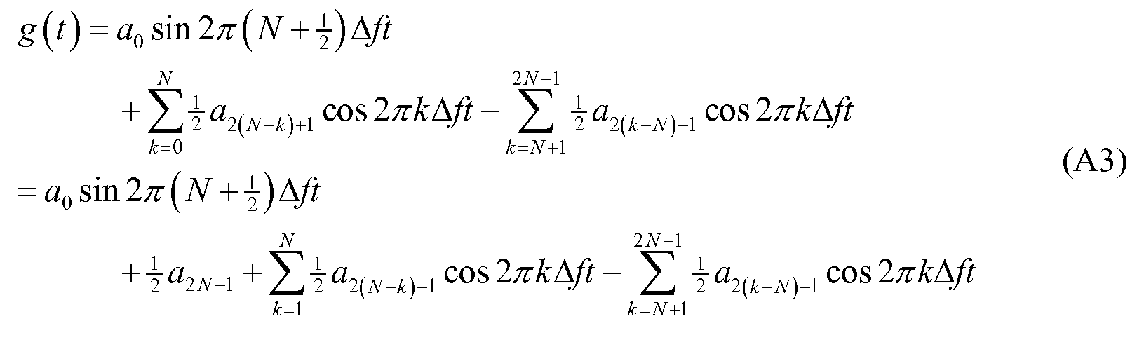
를 얻는다. .
s(t)에서 g(t)를 뺌으로써, By subtracting g (t) from s (t)
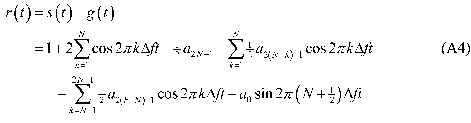
를 얻고, 이제, And now,
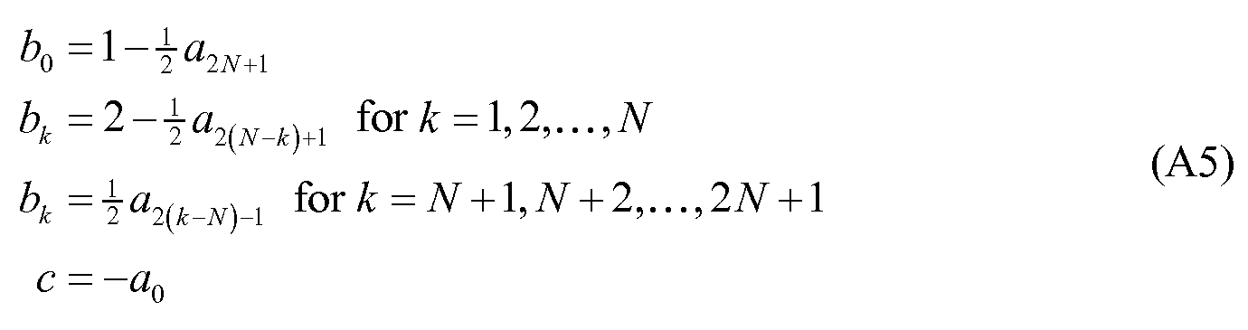
라고 둔다. "He says.
그럼, (A4)가 아래와 같이 쓰여질 수 있다:Then, (A4) can be written as:

Claims (44)
RF 트랜시버를 갖는 마스터 유닛과,
RF 트랜시버를 가지며, 상기 마스터 유닛과 인터페이싱하는 태그
를 포함하며,
상기 마스터 유닛은 태그와 인터페이싱하여, 태그까지의 거리를 측정하고,
마스터 유닛의 RF 트랜시버와 태그의 RF 트랜시버는 레인징 신호(ranging signal)를 송신하고 수신하도록 구성되고,
마스터 유닛의 RF 트랜시버는 레인징 신호를 송신하도록 구성되며,
태그의 RF 트랜시버는 레인징 신호를 수신하도록 구성되며,
상기 레인징 신호는 서로 다른 주파수의 복수의 펄스를 포함하고,
상기 레인징 신호는 마스터 유닛과 태그 사이의 거리를 측정하도록 사용되며,
하이-분해능 스펙트럼 추정 분석(high-resolution spectrum estimation analysis)이 사용되어서 거리 측정에서의 공간 모호성(spatial ambiguity)을 감소시키기 위해, 복수의 다중경로 주파수 성분에 대해 모델 크기를 추정하고, 모델 크기를 사용하여 직접 경로 신호를 결정하고, 상기 직접 경로 신호에 기초하여 거리를 계산하는 것을 특징으로 하는 RF-기반의 물체의 추적 및 위치찾기를 위한 시스템.A system for tracking and locating RF-based objects, the system comprising:
A master unit having an RF transceiver,
An RF transceiver, a tag for interfacing with the master unit,
/ RTI >
The master unit interfaces with the tag to measure the distance to the tag,
The RF transceiver of the master unit and the RF transceiver of the tag are configured to transmit and receive a ranging signal,
The RF transceiver of the master unit is configured to transmit a ranging signal,
The RF transceiver of the tag is configured to receive the ranging signal,
Wherein the ranging signal includes a plurality of pulses of different frequencies,
The ranging signal is used to measure the distance between the master unit and the tag,
A high-resolution spectrum estimation analysis is used to estimate the model size for a plurality of multipath frequency components to reduce the spatial ambiguity in the distance measurement and to use the model size To determine a direct path signal and to calculate a distance based on the direct path signal.
복수의 반환된 레인징 신호 및 기저대역 레인징 신호 개별 주파수 성분 샘플의 복소 진폭 샘플들의 평균이 구해져서, 신호 대 노이즈 비를 증가시킴으로써, 복소 진폭 결정 정확도가 개선되는 것을 특징으로 하는 RF-기반의 물체의 추적 및 위치찾기를 위한 시스템. 7. The method of claim 6, wherein the master and the tag receiver determine a complex amplitude of the returned ranging signal and the baseband ranging signal,
Characterized in that the complex amplitude determination accuracy is improved by averaging the complex amplitude samples of the plurality of returned ranging signals and the baseband ranging signal individual frequency component samples to increase the signal to noise ratio. A system for tracking and locating objects.
각각의 레인징 신호 시퀀스는, 태그에 의해 따로 따로 처리되어, 거리 측정 동안의 시간 딜레이가 결정되고, 각각의 태그는 각각의 레인징 신호에 대해 이동시간 차이(time of flight)를 계산하는 것을 특징으로 하는 RF-기반의 물체의 추적 및 위치찾기를 위한 시스템. 35. The method of claim 34, wherein each tag receives a first and a second ranging signal sequence, wherein a first ranging signal sequence is generated by a calling master unit and a second ranging signal sequence is generated by a satellite master unit Retransmitted,
Each ranging signal sequence is processed separately by the tag to determine a time delay during distance measurement and each tag calculates a time of flight for each ranging signal A system for tracking and locating RF-based objects.
DTOA(Differential Time of Arrival)를 이용하여, 또는 DTOA, 가상 삼각측량법 및 역-가상 삼각측량법의 조합을 이용하여, 마스터 유닛과 태그 간 거리 측정과 마스터 유닛과 마스터 유닛 간 거리 측정이 수행되는 것을 특징으로 하는 RF-기반의 물체의 추적 및 위치찾기를 위한 시스템. 36. The method of claim 35, wherein a time of flight of the first ranging signal and the second ranging signal is used to determine a position of the tag relative to the master unit,
The distance between the master unit and the tag and the distance between the master unit and the master unit are measured using a DTOA (Differential Time of Arrival) or a combination of DTOA, virtual triangulation and inverse virtual triangulation A system for tracking and locating RF-based objects.
상기 공분산 행렬은 경로 딜레이를 나타내는 개별 주파수의 추정치를 제공하고,
고유값은 직교하는 노이즈 고유벡터와 신호 고유벡터(부분공간)으로 분리되고, 개별 주파수는, 반환 신호의 관측치를 노이즈 공간으로 투사하고, 투사 에너지를 최소화함으로써 얻어지며,
회전-불변 신호 부분공간 속성으로부터 회전 조작자(rotation operator)가 결정되고, 개별 주파수는 상기 회전 조작자로부터 추정되는 것을 특징으로 하는 RF-기반의 물체의 추적 및 위치찾기를 위한 시스템. 3. The method of claim 1, wherein the high-resolution spectral estimation analysis uses an eigenvalue of a covariance matrix of the baseband ranging signal samples,
The covariance matrix provides an estimate of the individual frequency indicative of the path delay,
The eigenvalues are separated into orthogonal noise eigenvectors and signal eigenvectors (subspaces), the individual frequencies being obtained by projecting observations of the return signal to the noise space and minimizing the projection energy,
Wherein a rotation operator is determined from the rotation-invariant signal subspace property and an individual frequency is estimated from the rotation operator.
RF 트랜시버를 갖는 마스터 유닛과,
RF 트랜시버를 가지며, 상기 마스터 유닛과 인터페이싱하는 태그
를 포함하며,
상기 마스터 유닛은 태그와 인터페이싱하여, 태그까지의 거리를 측정하고,
마스터 유닛의 RF 트랜시버와 태그의 RF 트랜시버는 UHF 대역에서 협대역 레인징 신호(narrow bandwidth ranging signal)를 송신하고 수신하도록 구성되고,
마스터 유닛의 RF 트랜시버는 UHF 대역에서 협대역 레인징 신호를 송신하도록 구성되며,
태그의 RF 트랜시버는 UHF 대역에서 협대역 레인징 신호를 수신하도록 구성되며,
상기 협대역 레인징 신호는 서로 다른 주파수의 복수의 펄스를 포함하고,
상기 협대역 레인징 신호는 동일한 주파수의 복수의 펄스를 포함하고,
상기 레인징 신호는 (a) 복수의 주파수에서 하나의 펄스, 또는 (b) 하나의 주파수에서 복수의 펄스, 또는 (c) 여러 다른 주파수에서 복수의 펄스를 포함하고,
하이-분해능 스펙트럼 추정 분석이 사용되어서 거리 측정에서의 공간 모호성을 감소시키기 위해, 복수의 다중경로 주파수 성분에 대해 모델 크기를 추정하고, 모델 크기를 사용하여 직접 경로 신호를 결정하는 것을 특징으로 하는 RF-기반의 물체의 추적 및 위치찾기를 위한 시스템. A system for tracking and locating RF-based objects, the system comprising:
A master unit having an RF transceiver,
An RF transceiver, a tag for interfacing with the master unit,
/ RTI >
The master unit interfaces with the tag to measure the distance to the tag,
The RF transceiver of the master unit and the RF transceiver of the tag are configured to transmit and receive a narrow bandwidth ranging signal in the UHF band,
The RF transceiver of the master unit is configured to transmit a narrowband ranging signal in the UHF band,
The tag's RF transceiver is configured to receive a narrowband ranging signal in the UHF band,
Wherein the narrowband ranging signal includes a plurality of pulses of different frequencies,
Wherein the narrowband ranging signal comprises a plurality of pulses of the same frequency,
The ranging signal includes (a) one pulse at a plurality of frequencies, (b) a plurality of pulses at one frequency, or (c) a plurality of pulses at different frequencies,
Characterized in that a high-resolution spectral estimation analysis is used to estimate the model magnitude for a plurality of multipath frequency components and to determine a direct path signal using the model magnitude to reduce spatial ambiguity in the distance measurement - A system for tracking and locating objects based on the object.
RF 트랜시버를 갖는 마스터 유닛과,
RF 트랜시버를 가지며, 상기 마스터 유닛과 인터페이싱하는 태그
를 포함하며,
상기 마스터 유닛은 태그와 인터페이싱하여, 태그까지의 거리를 측정하고,
마스터 유닛의 RF 트랜시버와 태그의 RF 트랜시버는 레인징 신호(ranging signal)를 송신하고 수신하도록 구성되고,
마스터 유닛의 RF 트랜시버는 레인징 신호를 송신하도록 구성되며,
태그의 RF 트랜시버는 레인징 신호를 수신하도록 구성되며,
상기 레인징 신호는 (a) 복수의 주파수에서 하나의 펄스, 또는 (b) 하나의 주파수에서 복수의 펄스, 또는 (c) 여러 다른 주파수에서 복수의 펄스를 포함하고,
하이-분해능 스펙트럼 추정 분석이 사용되어서 거리 측정에서의 공간 모호성을 감소시키기 위해, 복수의 다중경로 주파수 성분에 대해 모델 크기를 추정하고, 모델 크기를 사용하여 직접 경로 신호를 결정하고, 상기 직접 경로 신호에 기초하여 거리를 계산하는 것을 특징으로 하는 RF-기반의 물체의 추적 및 위치찾기를 위한 시스템.A system for tracking and locating RF-based objects, the system comprising:
A master unit having an RF transceiver,
An RF transceiver, a tag for interfacing with the master unit,
/ RTI >
The master unit interfaces with the tag to measure the distance to the tag,
The RF transceiver of the master unit and the RF transceiver of the tag are configured to transmit and receive a ranging signal,
The RF transceiver of the master unit is configured to transmit a ranging signal,
The RF transceiver of the tag is configured to receive the ranging signal,
The ranging signal includes (a) one pulse at a plurality of frequencies, (b) a plurality of pulses at one frequency, or (c) a plurality of pulses at different frequencies,
A high-resolution spectral estimation analysis is used to estimate the model magnitude for a plurality of multipath frequency components to reduce spatial ambiguity in the distance measurement, determine the direct path signal using the model magnitude, Wherein the distance is calculated on the basis of the position of the object.
RF 트랜시버를 갖는 마스터 유닛과,
RF 트랜시버를 가지며, 상기 마스터 유닛과 인터페이싱하는 태그
를 포함하며,
상기 마스터 유닛은 태그 또는 또 다른 마스터 유닛과 인터페이싱하여, 태그 또는 또 다른 마스터 유닛까지의 거리를 측정하고,
마스터 유닛의 RF 트랜시버와 태그의 RF 트랜시버는 레인징 신호(ranging signal)를 송신하고 수신하도록 구성되고,
마스터 유닛의 RF 트랜시버는 레인징 신호를 송신하도록 구성되며,
태그의 RF 트랜시버는 레인징 신호를 수신하도록 구성되며,
상기 레인징 신호는 (a) 복수의 주파수에서 하나의 펄스, 또는 (b) 하나의 주파수에서 복수의 펄스, 또는 (c) 여러 다른 주파수에서 복수의 펄스를 포함하고,
레인징 신호는 마스터 유닛과 태그 유닛 간의 거리를 측정하기 위해 사용되고,
레인징 신호가 복수의 마스터 유닛들 간의 거리를 측정하기 위해 사용되며,
시스템은 수신된 레인징 신호의 복소 진폭을 계산하여, 마스터 유닛과 태그 간 거리 또는 마스터 유닛들 간 거리를 결정하고,
하이-분해능 스펙트럼 추정 분석이 사용되어서 거리 측정에서의 공간 모호성을 감소시키기 위해, 복수의 다중경로 주파수 성분에 대해 모델 크기를 추정하고, 모델 크기를 사용하여 직접 경로 신호를 결정하는 것을 특징으로 하는 RF-기반의 물체의 추적 및 위치찾기를 위한 시스템. A system for tracking and locating RF-based objects, the system comprising:
A master unit having an RF transceiver,
An RF transceiver, a tag for interfacing with the master unit,
/ RTI >
The master unit interfaces with the tag or another master unit to measure the distance to the tag or another master unit,
The RF transceiver of the master unit and the RF transceiver of the tag are configured to transmit and receive a ranging signal,
The RF transceiver of the master unit is configured to transmit a ranging signal,
The RF transceiver of the tag is configured to receive the ranging signal,
The ranging signal includes (a) one pulse at a plurality of frequencies, (b) a plurality of pulses at one frequency, or (c) a plurality of pulses at different frequencies,
The ranging signal is used to measure the distance between the master unit and the tag unit,
A ranging signal is used to measure the distance between the plurality of master units,
The system calculates the complex amplitude of the received ranging signal to determine the distance between the master unit and the tag or the distance between the master units,
Characterized in that a high-resolution spectral estimation analysis is used to estimate the model magnitude for a plurality of multipath frequency components and to determine a direct path signal using the model magnitude to reduce spatial ambiguity in the distance measurement - A system for tracking and locating objects based on the object.
RF 트랜시버를 갖는 마스터 유닛과,
RF 트랜시버를 가지며, 상기 마스터 유닛과 인터페이싱하는 태그
를 포함하며,
상기 마스터 유닛은 태그와 인터페이싱하여, 태그까지의 거리를 측정하고,
마스터 유닛의 RF 트랜시버와 태그의 RF 트랜시버는 레인징 신호(ranging signal)를 송신하고 수신하도록 구성되고,
마스터 유닛의 RF 트랜시버는 레인징 신호를 송신하도록 구성되며,
태그의 RF 트랜시버는 레인징 신호를 수신하도록 구성되며,
레인징 신호와 기저대역 레인징 신호의 서로 다른 주파수 성분이 의사랜덤 방식으로 선택되며,
(a) 이러한 성분들의 주파수는 연속(contiguous) 또는 이격되어 있거나, (b) 이러한 성분들은 동시에 또는 시간상 떨어져서 발생되거나, (c) (a)와 (b) 모두이고,
하이-분해능 스펙트럼 추정 분석이 사용되어서 거리 측정에서의 공간 모호성을 감소시키기 위해, 복수의 다중경로 주파수 성분에 대해 모델 크기를 추정하고, 모델 크기를 사용하여 직접 경로 신호를 결정하는 것을 특징으로 하는 RF-기반의 물체의 추적 및 위치찾기를 위한 시스템.
A system for tracking and locating RF-based objects, the system comprising:
A master unit having an RF transceiver,
An RF transceiver, a tag for interfacing with the master unit,
/ RTI >
The master unit interfaces with the tag to measure the distance to the tag,
The RF transceiver of the master unit and the RF transceiver of the tag are configured to transmit and receive a ranging signal,
The RF transceiver of the master unit is configured to transmit a ranging signal,
The RF transceiver of the tag is configured to receive the ranging signal,
The different frequency components of the ranging signal and the baseband ranging signal are selected in a pseudo-random manner,
(a) the frequencies of these components are contiguous or spaced, (b) these components occur simultaneously or in time, (c) both (a) and (b)
Characterized in that a high-resolution spectral estimation analysis is used to estimate the model magnitude for a plurality of multipath frequency components and to determine a direct path signal using the model magnitude to reduce spatial ambiguity in the distance measurement - A system for tracking and locating objects based on the object.
Applications Claiming Priority (5)
| Application Number | Priority Date | Filing Date | Title |
|---|---|---|---|
| US10327008P | 2008-10-07 | 2008-10-07 | |
| US61/103,270 | 2008-10-07 | ||
| US12/502,809 | 2009-07-14 | ||
| US12/502,809 US7872583B1 (en) | 2005-12-15 | 2009-07-14 | Methods and system for multi-path mitigation in tracking objects using reduced attenuation RF technology |
| PCT/US2009/059472 WO2010134933A1 (en) | 2008-10-07 | 2009-10-05 | Methods and system for multi-path mitigation in tracking objects using reduced attenuation rf technology |
Publications (2)
| Publication Number | Publication Date |
|---|---|
| KR20110067120A KR20110067120A (en) | 2011-06-21 |
| KR101728921B1 true KR101728921B1 (en) | 2017-04-20 |
Family
ID=43126423
Family Applications (1)
| Application Number | Title | Priority Date | Filing Date |
|---|---|---|---|
| KR1020117008061A Expired - Fee Related KR101728921B1 (en) | 2008-10-07 | 2009-10-05 | Methods and system for multi-path mitigation in tracking objects using reduced attenuation rf technology |
Country Status (6)
| Country | Link |
|---|---|
| US (1) | US7872583B1 (en) |
| EP (1) | EP2347280B1 (en) |
| JP (1) | JP5631320B2 (en) |
| KR (1) | KR101728921B1 (en) |
| CN (1) | CN102203634B (en) |
| WO (1) | WO2010134933A1 (en) |
Families Citing this family (71)
| Publication number | Priority date | Publication date | Assignee | Title |
|---|---|---|---|---|
| US9699607B2 (en) | 2005-12-15 | 2017-07-04 | Polte Corporation | Multi-path mitigation in rangefinding and tracking objects using reduced attenuation RF technology |
| US10091616B2 (en) | 2005-12-15 | 2018-10-02 | Polte Corporation | Angle of arrival (AOA) positioning method and system for positional finding and tracking objects using reduced attenuation RF technology |
| US9813867B2 (en) | 2005-12-15 | 2017-11-07 | Polte Corporation | Angle of arrival (AOA) positioning method and system for positional finding and tracking objects using reduced attenuation RF technology |
| US7969311B2 (en) | 2005-12-15 | 2011-06-28 | Invisitrack, Inc. | Multi-path mitigation in rangefinding and tracking objects using reduced attenuation RF technology |
| US9288623B2 (en) | 2005-12-15 | 2016-03-15 | Invisitrack, Inc. | Multi-path mitigation in rangefinding and tracking objects using reduced attenuation RF technology |
| US10281557B2 (en) | 2005-12-15 | 2019-05-07 | Polte Corporation | Partially synchronized multilateration/trilateration method and system for positional finding using RF |
| US10834531B2 (en) | 2005-12-15 | 2020-11-10 | Polte Corporation | Multi-path mitigation in rangefinding and tracking objects using reduced attenuation RF technology |
| US9913244B2 (en) | 2005-12-15 | 2018-03-06 | Polte Corporation | Partially synchronized multilateration or trilateration method and system for positional finding using RF |
| US8406280B2 (en) | 2008-03-18 | 2013-03-26 | Argon St, Inc. | System and method for mitigating severe multipath interference for geolocation and navigation |
| US8988284B2 (en) | 2008-08-14 | 2015-03-24 | Barry Brucker | System and method for tracking lost subjects |
| US9035829B2 (en) | 2008-09-10 | 2015-05-19 | Nextnav, Llc | Wide area positioning systems and methods |
| US9057606B2 (en) | 2009-09-10 | 2015-06-16 | Nextnav, Llc | Wide area positioning system |
| CA2736768A1 (en) | 2008-09-10 | 2010-03-18 | Commlabs, Inc. | Wide area positioning system |
| US9119165B2 (en) | 2009-09-10 | 2015-08-25 | Nextnav, Llc | Coding in a wide area positioning system (WAPS) |
| US8799345B1 (en) * | 2009-08-24 | 2014-08-05 | The United States Of America As Represented By The Secretary Of The Air Force | Low order multiple signal classification (MUSIC) method for high spectral resolution signal detection |
| US9291712B2 (en) | 2009-09-10 | 2016-03-22 | Nextnav, Llc | Cell organization and transmission schemes in a wide area positioning system (WAPS) |
| US9372266B2 (en) | 2009-09-10 | 2016-06-21 | Nextnav, Llc | Cell organization and transmission schemes in a wide area positioning system (WAPS) |
| US8779901B2 (en) * | 2010-04-13 | 2014-07-15 | Sunrise Micro Devices, Inc. | Asymmetric RTT ranging with multipath correction |
| WO2011128464A1 (en) * | 2010-04-16 | 2011-10-20 | Universitat Politècnica De Catalunya | Process and system for calculating distances between wireless nodes |
| US9753128B2 (en) * | 2010-07-23 | 2017-09-05 | Heptagon Micro Optics Pte. Ltd. | Multi-path compensation using multiple modulation frequencies in time of flight sensor |
| US9176217B2 (en) | 2011-08-02 | 2015-11-03 | Nextnav, Llc | Cell organization and transmission schemes in a wide area positioning system (WAPS) |
| JP6166260B2 (en) * | 2011-08-03 | 2017-07-19 | ポルテ・コーポレイションPoLTE Corporation | Multipath mitigation in object ranging and tracking using RF techniques with reduced attenuation |
| US11835639B2 (en) | 2011-08-03 | 2023-12-05 | Qualcomm Technologies, Inc. | Partially synchronized multilateration or trilateration method and system for positional finding using RF |
| US11125850B2 (en) | 2011-08-03 | 2021-09-21 | Polte Corporation | Systems and methods for determining a timing offset of emitter antennas in a wireless network |
| US8937554B2 (en) | 2011-09-28 | 2015-01-20 | Silverplus, Inc. | Low power location-tracking device with combined short-range and wide-area wireless and location capabilities |
| KR20150024880A (en) | 2012-06-05 | 2015-03-09 | 넥스트나브, 엘엘씨 | Systems and methods for location positioning of user device |
| CN102778872B (en) * | 2012-07-05 | 2014-07-23 | 北京交通大学 | Real-time correction method for dynamic displacement of track circuit reader signal carrier frequency |
| US10440512B2 (en) | 2012-08-03 | 2019-10-08 | Polte Corporation | Angle of arrival (AOA) positioning method and system for positional finding and tracking objects using reduced attenuation RF technology |
| US10863313B2 (en) | 2014-08-01 | 2020-12-08 | Polte Corporation | Network architecture and methods for location services |
| US10845453B2 (en) | 2012-08-03 | 2020-11-24 | Polte Corporation | Network architecture and methods for location services |
| US9390279B2 (en) | 2012-09-11 | 2016-07-12 | Nextnav, Llc | Systems and methods for providing conditional access to transmitted information |
| US9286490B2 (en) | 2013-09-10 | 2016-03-15 | Nextnav, Llc | Systems and methods for providing conditional access to transmitted information |
| US10735298B2 (en) | 2012-12-05 | 2020-08-04 | Origin Wireless, Inc. | Method, apparatus, server and system for vital sign detection and monitoring |
| US11012285B2 (en) | 2012-12-05 | 2021-05-18 | Origin Wireless, Inc. | Methods, apparatus, servers, and systems for vital signs detection and monitoring |
| US10495725B2 (en) | 2012-12-05 | 2019-12-03 | Origin Wireless, Inc. | Method, apparatus, server and system for real-time vital sign detection and monitoring |
| KR101360663B1 (en) * | 2012-09-24 | 2014-02-10 | 재단법인대구경북과학기술원 | High precision pulse doppler radar and method for detecting target thereof |
| US8824272B2 (en) * | 2012-10-09 | 2014-09-02 | The Aerospace Corporation | Resolving co-channel interference between overlapping users using rank selection |
| CN110895326B (en) * | 2012-12-12 | 2024-03-22 | 高通科技公司 | Method for determining the position of a user equipment in a wireless system |
| JP6639237B2 (en) | 2013-03-07 | 2020-02-05 | テルコム・ベンチャーズ・エルエルシー | Method, location network center, and location network receiver |
| US10203397B2 (en) | 2013-03-15 | 2019-02-12 | Nextnav, Llc | Methods and apparatus for improving time of arrival determination |
| IL227285A0 (en) * | 2013-07-01 | 2013-12-31 | Rami Goldreich | Mitigation of multipath distortions for tdoa-based geolocation |
| EP3349032A1 (en) | 2014-10-24 | 2018-07-18 | Polte Corporation | Partially synchronized multilateration or trilateration method and system for positional finding using rf |
| US20160179748A1 (en) * | 2014-12-18 | 2016-06-23 | Lawrence R. Weill | Method and apparatus for estimating waveform onset time |
| WO2016131184A1 (en) * | 2015-02-16 | 2016-08-25 | 华为技术有限公司 | Distance measuring method and device |
| CN105139047B (en) * | 2015-08-19 | 2018-07-31 | 南京理工大学 | The chipless RFID system of polarization |
| JP2018538515A (en) | 2015-10-08 | 2018-12-27 | ポルテ・コーポレイションPoLTE Corporation | Angle-of-arrival positioning system for object tracking |
| US9721582B1 (en) * | 2016-02-03 | 2017-08-01 | Google Inc. | Globally optimized least-squares post-filtering for speech enhancement |
| EP3414599B1 (en) * | 2016-02-08 | 2019-12-18 | Denso Corporation | Time-of-flight distance measuring device and method for detecting multipath error |
| JP6900390B2 (en) * | 2016-03-11 | 2021-07-07 | オリジン ワイヤレス, インコーポレイテッドOrigin Wireless, Inc. | Methods, devices, servers and systems for detecting and monitoring vital signs |
| US10206193B2 (en) | 2016-08-31 | 2019-02-12 | At&T Intellectual Property, L.P. | Mobile device location based on detection of radiation sources |
| EP3293547B1 (en) * | 2016-09-13 | 2023-07-05 | Centre National d'Etudes Spatiales | Cepstrum-based multipath mitigation of a spread spectrum radiocommunication signal |
| US10345438B2 (en) * | 2016-09-19 | 2019-07-09 | Commscope Technologies Llc | Determining distance to source of passive intermodulation product (PIM) in a distributed base station |
| CN107994920B (en) * | 2017-11-22 | 2019-10-18 | 南京理工大学 | A coherent signal forwarding method for a cube satellite measurement and control transponder |
| US10679173B2 (en) | 2018-02-19 | 2020-06-09 | Rpmanetworks Holdings | End to end logistic chain tracking and control of shipping containers |
| US11255945B2 (en) | 2018-03-27 | 2022-02-22 | Polte Corporation | Multi-path mitigation in tracking objects using compressed RF data |
| EP3668197B1 (en) | 2018-12-12 | 2021-11-03 | Rohde & Schwarz GmbH & Co. KG | Method and radio for setting the transmission power of a radio transmission |
| JP7357217B2 (en) * | 2018-12-28 | 2023-10-06 | パナソニックIpマネジメント株式会社 | Estimation method, estimation device, and program |
| CN110673097B (en) * | 2019-10-24 | 2022-01-18 | 浙江工商大学 | Method for positioning sounding object in space by using audio arrival time difference |
| WO2021117298A1 (en) * | 2019-12-12 | 2021-06-17 | コニカミノルタ株式会社 | Collating device, learning devcie, and program |
| EP3839562B1 (en) | 2019-12-20 | 2024-09-18 | Stichting IMEC Nederland | Method for distance determination |
| CN111812581B (en) * | 2020-06-16 | 2023-11-14 | 重庆大学 | Spherical array sound source direction-of-arrival estimation method based on atomic norms |
| EP3929620B1 (en) | 2020-06-26 | 2024-07-24 | Stichting IMEC Nederland | Ranging method |
| JP7434130B2 (en) | 2020-09-24 | 2024-02-20 | 株式会社東芝 | Distance measuring device and method |
| US11815616B2 (en) * | 2020-11-02 | 2023-11-14 | Apple Inc. | Announcing UWB / NBA-UWB-MMS ranging rounds via narrowband-based advertisements |
| US11635505B2 (en) * | 2021-02-09 | 2023-04-25 | Qualcomm Incorporated | UE passive RF sensing with cellular-based bistatic/multistatic radar |
| US11950567B2 (en) | 2021-03-04 | 2024-04-09 | Sky View Environmental Service Llc | Condor monitoring systems and related methods |
| US20230124956A1 (en) * | 2021-10-20 | 2023-04-20 | AyDeeKay LLC dba Indie Semiconductor | Signal-Adaptive and Time-Dependent Analog-to-Digital Conversion Rate in a Ranging Receiver |
| KR102516903B1 (en) * | 2021-11-11 | 2023-04-03 | 한국전자통신연구원 | Method and apparatus for simultaneous power estimation of multiple signal sources in communication system |
| US12160298B2 (en) | 2022-05-24 | 2024-12-03 | Samsung Electronics Co., Ltd. | Multi-antenna WiFi based breathing rate estimation |
| CN115189781B (en) * | 2022-06-02 | 2024-04-09 | 中国信息通信研究院 | System and method for calibrating bandwidth occupied by instrument and meter |
| JPWO2024147248A1 (en) * | 2023-01-05 | 2024-07-11 |
Citations (2)
| Publication number | Priority date | Publication date | Assignee | Title |
|---|---|---|---|---|
| US6812824B1 (en) | 1996-10-17 | 2004-11-02 | Rf Technologies, Inc. | Method and apparatus combining a tracking system and a wireless communication system |
| US20060244661A1 (en) * | 2004-09-10 | 2006-11-02 | Worcester Polytechnic Institute | Methods and apparatus for high resolution positioning |
Family Cites Families (14)
| Publication number | Priority date | Publication date | Assignee | Title |
|---|---|---|---|---|
| US4455556A (en) * | 1980-05-19 | 1984-06-19 | Nippon Electric Co., Ltd. | Distance measuring equipment |
| DK0467036T3 (en) * | 1990-06-15 | 1996-03-11 | Savi Techn Inc | Radio identification and tracking method and apparatus |
| US5774876A (en) * | 1996-06-26 | 1998-06-30 | Par Government Systems Corporation | Managing assets with active electronic tags |
| US6211818B1 (en) * | 1999-07-01 | 2001-04-03 | Howard L. Zach, Sr. | Automatic moving vehicle alert |
| WO2002023218A2 (en) * | 2000-09-14 | 2002-03-21 | Time Domain Corporation | System and method for detecting an intruder using impulse radio technology |
| US6788199B2 (en) * | 2001-03-12 | 2004-09-07 | Eureka Technology Partners, Llc | Article locator system |
| DE10231597A1 (en) * | 2002-07-12 | 2004-01-29 | Robert Bosch Gmbh | Method and radar system for determining the directional angle of radar objects |
| KR20050014051A (en) * | 2003-07-29 | 2005-02-07 | 안희태 | Distance Measuring Method and Device by Frequency Separation with Ultrasonic |
| US6977612B1 (en) * | 2004-06-29 | 2005-12-20 | Electronic Data Systems Corporation | System and method for wireless asset tracking |
| JP2008509869A (en) * | 2004-08-12 | 2008-04-03 | ウェアネット・コープ | System and method for tracking containers in grounded marine terminal operations |
| US7649491B2 (en) * | 2005-03-09 | 2010-01-19 | Omron Corporation | Distance measuring apparatus, distance measuring method, reflector and communication system |
| US7561048B2 (en) * | 2005-12-15 | 2009-07-14 | Invisitrack, Inc. | Methods and system for reduced attenuation in tracking objects using RF technology |
| JP5247056B2 (en) * | 2006-04-03 | 2013-07-24 | 三菱電機株式会社 | Propagation delay time measuring apparatus and radar apparatus |
| US7518502B2 (en) * | 2007-05-24 | 2009-04-14 | Smith & Nephew, Inc. | System and method for tracking surgical assets |
-
2009
- 2009-07-14 US US12/502,809 patent/US7872583B1/en active Active
- 2009-10-05 JP JP2011530285A patent/JP5631320B2/en not_active Expired - Fee Related
- 2009-10-05 WO PCT/US2009/059472 patent/WO2010134933A1/en not_active Ceased
- 2009-10-05 CN CN2009801391033A patent/CN102203634B/en active Active
- 2009-10-05 KR KR1020117008061A patent/KR101728921B1/en not_active Expired - Fee Related
- 2009-10-05 EP EP09845044.8A patent/EP2347280B1/en active Active
Patent Citations (2)
| Publication number | Priority date | Publication date | Assignee | Title |
|---|---|---|---|---|
| US6812824B1 (en) | 1996-10-17 | 2004-11-02 | Rf Technologies, Inc. | Method and apparatus combining a tracking system and a wireless communication system |
| US20060244661A1 (en) * | 2004-09-10 | 2006-11-02 | Worcester Polytechnic Institute | Methods and apparatus for high resolution positioning |
Also Published As
| Publication number | Publication date |
|---|---|
| EP2347280A1 (en) | 2011-07-27 |
| JP2012513014A (en) | 2012-06-07 |
| US7872583B1 (en) | 2011-01-18 |
| EP2347280A4 (en) | 2014-04-23 |
| WO2010134933A1 (en) | 2010-11-25 |
| JP5631320B2 (en) | 2014-11-26 |
| CN102203634B (en) | 2013-10-30 |
| CN102203634A (en) | 2011-09-28 |
| KR20110067120A (en) | 2011-06-21 |
| EP2347280B1 (en) | 2017-06-14 |
Similar Documents
| Publication | Publication Date | Title |
|---|---|---|
| KR101728921B1 (en) | Methods and system for multi-path mitigation in tracking objects using reduced attenuation rf technology | |
| US7969311B2 (en) | Multi-path mitigation in rangefinding and tracking objects using reduced attenuation RF technology | |
| US11722840B2 (en) | Angle of arrival (AOA) positioning method and system for positional finding and tracking objects using reduced attenuation RF technology | |
| JP6970720B2 (en) | Arrival angle positioning system for tracking objects | |
| US10433111B2 (en) | Angle of arrival (AOA) positioning method and system for positional finding and tracking objects using reduced attenuation RF technology | |
| US9813867B2 (en) | Angle of arrival (AOA) positioning method and system for positional finding and tracking objects using reduced attenuation RF technology | |
| KR102145095B1 (en) | Partially synchronized multilateration or trilateration method and system for positional finding using rf | |
| KR101995213B1 (en) | Multi-path mitigation in rangefinding and tracking objects using reduced attenuation rf technology | |
| KR102278860B1 (en) | Multi-path mitigation in rangefinding and tracking objects using reduced attenuation rf technology | |
| Hou et al. | Indoor localization for Bluetooth low energy using wavelet and smoothing filter | |
| Tian et al. | Passive localization via on-the-air LTE signals | |
| HK1160224B (en) | Methods and system for multi-path mitigation in tracking objects using reduced attenuation rf technology | |
| HK1160224A (en) | Methods and system for multi-path mitigation in tracking objects using reduced attenuation rf technology | |
| Marx et al. | Time synchronization for Real Time Localization Systems with multi path mitigation | |
| Reggiani et al. | An algorithm for mapping the positions of point scatterers | |
| Jemai et al. | An advanced IEEE 802.1 IB channel sounder based on PN correlation and high resolution algorithms | |
| Marx | System issues for time synchronization in Real Time Localization Systems with multi path mitigation | |
| Marx et al. | High Resolution Delay Locked Loop for time synchronization with multi path mitigation |
Legal Events
| Date | Code | Title | Description |
|---|---|---|---|
| PA0105 | International application |
St.27 status event code: A-0-1-A10-A15-nap-PA0105 |
|
| PG1501 | Laying open of application |
St.27 status event code: A-1-1-Q10-Q12-nap-PG1501 |
|
| R18-X000 | Changes to party contact information recorded |
St.27 status event code: A-3-3-R10-R18-oth-X000 |
|
| A201 | Request for examination | ||
| PA0201 | Request for examination |
St.27 status event code: A-1-2-D10-D11-exm-PA0201 |
|
| R17-X000 | Change to representative recorded |
St.27 status event code: A-3-3-R10-R17-oth-X000 |
|
| E902 | Notification of reason for refusal | ||
| PE0902 | Notice of grounds for rejection |
St.27 status event code: A-1-2-D10-D21-exm-PE0902 |
|
| R18-X000 | Changes to party contact information recorded |
St.27 status event code: A-3-3-R10-R18-oth-X000 |
|
| T11-X000 | Administrative time limit extension requested |
St.27 status event code: U-3-3-T10-T11-oth-X000 |
|
| T11-X000 | Administrative time limit extension requested |
St.27 status event code: U-3-3-T10-T11-oth-X000 |
|
| T11-X000 | Administrative time limit extension requested |
St.27 status event code: U-3-3-T10-T11-oth-X000 |
|
| P11-X000 | Amendment of application requested |
St.27 status event code: A-2-2-P10-P11-nap-X000 |
|
| P13-X000 | Application amended |
St.27 status event code: A-2-2-P10-P13-nap-X000 |
|
| E902 | Notification of reason for refusal | ||
| PE0902 | Notice of grounds for rejection |
St.27 status event code: A-1-2-D10-D21-exm-PE0902 |
|
| P11-X000 | Amendment of application requested |
St.27 status event code: A-2-2-P10-P11-nap-X000 |
|
| P13-X000 | Application amended |
St.27 status event code: A-2-2-P10-P13-nap-X000 |
|
| E701 | Decision to grant or registration of patent right | ||
| PE0701 | Decision of registration |
St.27 status event code: A-1-2-D10-D22-exm-PE0701 |
|
| R18-X000 | Changes to party contact information recorded |
St.27 status event code: A-3-3-R10-R18-oth-X000 |
|
| PR0701 | Registration of establishment |
St.27 status event code: A-2-4-F10-F11-exm-PR0701 |
|
| PR1002 | Payment of registration fee |
St.27 status event code: A-2-2-U10-U12-oth-PR1002 Fee payment year number: 1 |
|
| PG1601 | Publication of registration |
St.27 status event code: A-4-4-Q10-Q13-nap-PG1601 |
|
| R18-X000 | Changes to party contact information recorded |
St.27 status event code: A-5-5-R10-R18-oth-X000 |
|
| PR1001 | Payment of annual fee |
St.27 status event code: A-4-4-U10-U11-oth-PR1001 Fee payment year number: 4 |
|
| PR1001 | Payment of annual fee |
St.27 status event code: A-4-4-U10-U11-oth-PR1001 Fee payment year number: 5 |
|
| PR1001 | Payment of annual fee |
St.27 status event code: A-4-4-U10-U11-oth-PR1001 Fee payment year number: 6 |
|
| R18-X000 | Changes to party contact information recorded |
St.27 status event code: A-5-5-R10-R18-oth-X000 |
|
| PN2301 | Change of applicant |
St.27 status event code: A-5-5-R10-R11-asn-PN2301 |
|
| PN2301 | Change of applicant |
St.27 status event code: A-5-5-R10-R14-asn-PN2301 |
|
| PR1001 | Payment of annual fee |
St.27 status event code: A-4-4-U10-U11-oth-PR1001 Fee payment year number: 7 |
|
| PR1001 | Payment of annual fee |
St.27 status event code: A-4-4-U10-U11-oth-PR1001 Fee payment year number: 8 |
|
| PN2301 | Change of applicant |
St.27 status event code: A-5-5-R10-R11-asn-PN2301 |
|
| PN2301 | Change of applicant |
St.27 status event code: A-5-5-R10-R14-asn-PN2301 |
|
| PC1903 | Unpaid annual fee |
St.27 status event code: A-4-4-U10-U13-oth-PC1903 Not in force date: 20250415 Payment event data comment text: Termination Category : DEFAULT_OF_REGISTRATION_FEE |
|
| PC1903 | Unpaid annual fee |
St.27 status event code: N-4-6-H10-H13-oth-PC1903 Ip right cessation event data comment text: Termination Category : DEFAULT_OF_REGISTRATION_FEE Not in force date: 20250415 |