KR101702589B1 - Different form of display device having hole - Google Patents
Different form of display device having hole Download PDFInfo
- Publication number
- KR101702589B1 KR101702589B1 KR1020150169191A KR20150169191A KR101702589B1 KR 101702589 B1 KR101702589 B1 KR 101702589B1 KR 1020150169191 A KR1020150169191 A KR 1020150169191A KR 20150169191 A KR20150169191 A KR 20150169191A KR 101702589 B1 KR101702589 B1 KR 101702589B1
- Authority
- KR
- South Korea
- Prior art keywords
- hole
- liquid crystal
- lower cover
- crystal panel
- guide plate
- Prior art date
- Legal status (The legal status is an assumption and is not a legal conclusion. Google has not performed a legal analysis and makes no representation as to the accuracy of the status listed.)
- Active
Links
Images


Classifications
-
- G—PHYSICS
- G02—OPTICS
- G02F—OPTICAL DEVICES OR ARRANGEMENTS FOR THE CONTROL OF LIGHT BY MODIFICATION OF THE OPTICAL PROPERTIES OF THE MEDIA OF THE ELEMENTS INVOLVED THEREIN; NON-LINEAR OPTICS; FREQUENCY-CHANGING OF LIGHT; OPTICAL LOGIC ELEMENTS; OPTICAL ANALOGUE/DIGITAL CONVERTERS
- G02F1/00—Devices or arrangements for the control of the intensity, colour, phase, polarisation or direction of light arriving from an independent light source, e.g. switching, gating or modulating; Non-linear optics
- G02F1/01—Devices or arrangements for the control of the intensity, colour, phase, polarisation or direction of light arriving from an independent light source, e.g. switching, gating or modulating; Non-linear optics for the control of the intensity, phase, polarisation or colour
- G02F1/13—Devices or arrangements for the control of the intensity, colour, phase, polarisation or direction of light arriving from an independent light source, e.g. switching, gating or modulating; Non-linear optics for the control of the intensity, phase, polarisation or colour based on liquid crystals, e.g. single liquid crystal display cells
- G02F1/133—Constructional arrangements; Operation of liquid crystal cells; Circuit arrangements
- G02F1/1333—Constructional arrangements; Manufacturing methods
- G02F1/133308—Support structures for LCD panels, e.g. frames or bezels
-
- G—PHYSICS
- G02—OPTICS
- G02B—OPTICAL ELEMENTS, SYSTEMS OR APPARATUS
- G02B6/00—Light guides; Structural details of arrangements comprising light guides and other optical elements, e.g. couplings
- G02B6/0001—Light guides; Structural details of arrangements comprising light guides and other optical elements, e.g. couplings specially adapted for lighting devices or systems
- G02B6/0011—Light guides; Structural details of arrangements comprising light guides and other optical elements, e.g. couplings specially adapted for lighting devices or systems the light guides being planar or of plate-like form
- G02B6/0033—Means for improving the coupling-out of light from the light guide
- G02B6/005—Means for improving the coupling-out of light from the light guide provided by one optical element, or plurality thereof, placed on the light output side of the light guide
- G02B6/0055—Reflecting element, sheet or layer
-
- G—PHYSICS
- G02—OPTICS
- G02B—OPTICAL ELEMENTS, SYSTEMS OR APPARATUS
- G02B6/00—Light guides; Structural details of arrangements comprising light guides and other optical elements, e.g. couplings
- G02B6/0001—Light guides; Structural details of arrangements comprising light guides and other optical elements, e.g. couplings specially adapted for lighting devices or systems
- G02B6/0011—Light guides; Structural details of arrangements comprising light guides and other optical elements, e.g. couplings specially adapted for lighting devices or systems the light guides being planar or of plate-like form
- G02B6/0081—Mechanical or electrical aspects of the light guide and light source in the lighting device peculiar to the adaptation to planar light guides, e.g. concerning packaging
- G02B6/0086—Positioning aspects
- G02B6/0088—Positioning aspects of the light guide or other optical sheets in the package
-
- G—PHYSICS
- G02—OPTICS
- G02B—OPTICAL ELEMENTS, SYSTEMS OR APPARATUS
- G02B6/00—Light guides; Structural details of arrangements comprising light guides and other optical elements, e.g. couplings
- G02B6/0001—Light guides; Structural details of arrangements comprising light guides and other optical elements, e.g. couplings specially adapted for lighting devices or systems
- G02B6/0011—Light guides; Structural details of arrangements comprising light guides and other optical elements, e.g. couplings specially adapted for lighting devices or systems the light guides being planar or of plate-like form
- G02B6/0081—Mechanical or electrical aspects of the light guide and light source in the lighting device peculiar to the adaptation to planar light guides, e.g. concerning packaging
- G02B6/0086—Positioning aspects
- G02B6/0091—Positioning aspects of the light source relative to the light guide
-
- G—PHYSICS
- G02—OPTICS
- G02F—OPTICAL DEVICES OR ARRANGEMENTS FOR THE CONTROL OF LIGHT BY MODIFICATION OF THE OPTICAL PROPERTIES OF THE MEDIA OF THE ELEMENTS INVOLVED THEREIN; NON-LINEAR OPTICS; FREQUENCY-CHANGING OF LIGHT; OPTICAL LOGIC ELEMENTS; OPTICAL ANALOGUE/DIGITAL CONVERTERS
- G02F1/00—Devices or arrangements for the control of the intensity, colour, phase, polarisation or direction of light arriving from an independent light source, e.g. switching, gating or modulating; Non-linear optics
- G02F1/01—Devices or arrangements for the control of the intensity, colour, phase, polarisation or direction of light arriving from an independent light source, e.g. switching, gating or modulating; Non-linear optics for the control of the intensity, phase, polarisation or colour
- G02F1/13—Devices or arrangements for the control of the intensity, colour, phase, polarisation or direction of light arriving from an independent light source, e.g. switching, gating or modulating; Non-linear optics for the control of the intensity, phase, polarisation or colour based on liquid crystals, e.g. single liquid crystal display cells
- G02F1/133—Constructional arrangements; Operation of liquid crystal cells; Circuit arrangements
- G02F1/1333—Constructional arrangements; Manufacturing methods
- G02F1/1335—Structural association of cells with optical devices, e.g. polarisers or reflectors
- G02F1/1336—Illuminating devices
- G02F1/133602—Direct backlight
- G02F1/133608—Direct backlight including particular frames or supporting means
-
- G—PHYSICS
- G02—OPTICS
- G02F—OPTICAL DEVICES OR ARRANGEMENTS FOR THE CONTROL OF LIGHT BY MODIFICATION OF THE OPTICAL PROPERTIES OF THE MEDIA OF THE ELEMENTS INVOLVED THEREIN; NON-LINEAR OPTICS; FREQUENCY-CHANGING OF LIGHT; OPTICAL LOGIC ELEMENTS; OPTICAL ANALOGUE/DIGITAL CONVERTERS
- G02F1/00—Devices or arrangements for the control of the intensity, colour, phase, polarisation or direction of light arriving from an independent light source, e.g. switching, gating or modulating; Non-linear optics
- G02F1/01—Devices or arrangements for the control of the intensity, colour, phase, polarisation or direction of light arriving from an independent light source, e.g. switching, gating or modulating; Non-linear optics for the control of the intensity, phase, polarisation or colour
- G02F1/13—Devices or arrangements for the control of the intensity, colour, phase, polarisation or direction of light arriving from an independent light source, e.g. switching, gating or modulating; Non-linear optics for the control of the intensity, phase, polarisation or colour based on liquid crystals, e.g. single liquid crystal display cells
- G02F1/133—Constructional arrangements; Operation of liquid crystal cells; Circuit arrangements
- G02F1/1333—Constructional arrangements; Manufacturing methods
- G02F1/1335—Structural association of cells with optical devices, e.g. polarisers or reflectors
- G02F1/1336—Illuminating devices
- G02F1/133615—Edge-illuminating devices, i.e. illuminating from the side
-
- G—PHYSICS
- G02—OPTICS
- G02F—OPTICAL DEVICES OR ARRANGEMENTS FOR THE CONTROL OF LIGHT BY MODIFICATION OF THE OPTICAL PROPERTIES OF THE MEDIA OF THE ELEMENTS INVOLVED THEREIN; NON-LINEAR OPTICS; FREQUENCY-CHANGING OF LIGHT; OPTICAL LOGIC ELEMENTS; OPTICAL ANALOGUE/DIGITAL CONVERTERS
- G02F1/00—Devices or arrangements for the control of the intensity, colour, phase, polarisation or direction of light arriving from an independent light source, e.g. switching, gating or modulating; Non-linear optics
- G02F1/01—Devices or arrangements for the control of the intensity, colour, phase, polarisation or direction of light arriving from an independent light source, e.g. switching, gating or modulating; Non-linear optics for the control of the intensity, phase, polarisation or colour
- G02F1/13—Devices or arrangements for the control of the intensity, colour, phase, polarisation or direction of light arriving from an independent light source, e.g. switching, gating or modulating; Non-linear optics for the control of the intensity, phase, polarisation or colour based on liquid crystals, e.g. single liquid crystal display cells
- G02F1/133—Constructional arrangements; Operation of liquid crystal cells; Circuit arrangements
- G02F1/1333—Constructional arrangements; Manufacturing methods
- G02F1/1339—Gaskets; Spacers; Sealing of cells
-
- G—PHYSICS
- G02—OPTICS
- G02B—OPTICAL ELEMENTS, SYSTEMS OR APPARATUS
- G02B6/00—Light guides; Structural details of arrangements comprising light guides and other optical elements, e.g. couplings
- G02B6/0001—Light guides; Structural details of arrangements comprising light guides and other optical elements, e.g. couplings specially adapted for lighting devices or systems
- G02B6/0011—Light guides; Structural details of arrangements comprising light guides and other optical elements, e.g. couplings specially adapted for lighting devices or systems the light guides being planar or of plate-like form
- G02B6/0081—Mechanical or electrical aspects of the light guide and light source in the lighting device peculiar to the adaptation to planar light guides, e.g. concerning packaging
- G02B6/0083—Details of electrical connections of light sources to drivers, circuit boards, or the like
-
- G—PHYSICS
- G02—OPTICS
- G02F—OPTICAL DEVICES OR ARRANGEMENTS FOR THE CONTROL OF LIGHT BY MODIFICATION OF THE OPTICAL PROPERTIES OF THE MEDIA OF THE ELEMENTS INVOLVED THEREIN; NON-LINEAR OPTICS; FREQUENCY-CHANGING OF LIGHT; OPTICAL LOGIC ELEMENTS; OPTICAL ANALOGUE/DIGITAL CONVERTERS
- G02F1/00—Devices or arrangements for the control of the intensity, colour, phase, polarisation or direction of light arriving from an independent light source, e.g. switching, gating or modulating; Non-linear optics
- G02F1/01—Devices or arrangements for the control of the intensity, colour, phase, polarisation or direction of light arriving from an independent light source, e.g. switching, gating or modulating; Non-linear optics for the control of the intensity, phase, polarisation or colour
- G02F1/13—Devices or arrangements for the control of the intensity, colour, phase, polarisation or direction of light arriving from an independent light source, e.g. switching, gating or modulating; Non-linear optics for the control of the intensity, phase, polarisation or colour based on liquid crystals, e.g. single liquid crystal display cells
- G02F1/133—Constructional arrangements; Operation of liquid crystal cells; Circuit arrangements
- G02F1/1333—Constructional arrangements; Manufacturing methods
- G02F1/133308—Support structures for LCD panels, e.g. frames or bezels
- G02F1/133314—Back frames
-
- G—PHYSICS
- G02—OPTICS
- G02F—OPTICAL DEVICES OR ARRANGEMENTS FOR THE CONTROL OF LIGHT BY MODIFICATION OF THE OPTICAL PROPERTIES OF THE MEDIA OF THE ELEMENTS INVOLVED THEREIN; NON-LINEAR OPTICS; FREQUENCY-CHANGING OF LIGHT; OPTICAL LOGIC ELEMENTS; OPTICAL ANALOGUE/DIGITAL CONVERTERS
- G02F1/00—Devices or arrangements for the control of the intensity, colour, phase, polarisation or direction of light arriving from an independent light source, e.g. switching, gating or modulating; Non-linear optics
- G02F1/01—Devices or arrangements for the control of the intensity, colour, phase, polarisation or direction of light arriving from an independent light source, e.g. switching, gating or modulating; Non-linear optics for the control of the intensity, phase, polarisation or colour
- G02F1/13—Devices or arrangements for the control of the intensity, colour, phase, polarisation or direction of light arriving from an independent light source, e.g. switching, gating or modulating; Non-linear optics for the control of the intensity, phase, polarisation or colour based on liquid crystals, e.g. single liquid crystal display cells
- G02F1/133—Constructional arrangements; Operation of liquid crystal cells; Circuit arrangements
- G02F1/1333—Constructional arrangements; Manufacturing methods
- G02F1/133308—Support structures for LCD panels, e.g. frames or bezels
- G02F1/13332—Front frames
-
- G—PHYSICS
- G02—OPTICS
- G02F—OPTICAL DEVICES OR ARRANGEMENTS FOR THE CONTROL OF LIGHT BY MODIFICATION OF THE OPTICAL PROPERTIES OF THE MEDIA OF THE ELEMENTS INVOLVED THEREIN; NON-LINEAR OPTICS; FREQUENCY-CHANGING OF LIGHT; OPTICAL LOGIC ELEMENTS; OPTICAL ANALOGUE/DIGITAL CONVERTERS
- G02F1/00—Devices or arrangements for the control of the intensity, colour, phase, polarisation or direction of light arriving from an independent light source, e.g. switching, gating or modulating; Non-linear optics
- G02F1/01—Devices or arrangements for the control of the intensity, colour, phase, polarisation or direction of light arriving from an independent light source, e.g. switching, gating or modulating; Non-linear optics for the control of the intensity, phase, polarisation or colour
- G02F1/13—Devices or arrangements for the control of the intensity, colour, phase, polarisation or direction of light arriving from an independent light source, e.g. switching, gating or modulating; Non-linear optics for the control of the intensity, phase, polarisation or colour based on liquid crystals, e.g. single liquid crystal display cells
- G02F1/133—Constructional arrangements; Operation of liquid crystal cells; Circuit arrangements
- G02F1/1333—Constructional arrangements; Manufacturing methods
- G02F1/133308—Support structures for LCD panels, e.g. frames or bezels
- G02F1/133322—Mechanical guidance or alignment of LCD panel support components
-
- G—PHYSICS
- G02—OPTICS
- G02F—OPTICAL DEVICES OR ARRANGEMENTS FOR THE CONTROL OF LIGHT BY MODIFICATION OF THE OPTICAL PROPERTIES OF THE MEDIA OF THE ELEMENTS INVOLVED THEREIN; NON-LINEAR OPTICS; FREQUENCY-CHANGING OF LIGHT; OPTICAL LOGIC ELEMENTS; OPTICAL ANALOGUE/DIGITAL CONVERTERS
- G02F2201/00—Constructional arrangements not provided for in groups G02F1/00 - G02F7/00
- G02F2201/46—Fixing elements
-
- G—PHYSICS
- G02—OPTICS
- G02F—OPTICAL DEVICES OR ARRANGEMENTS FOR THE CONTROL OF LIGHT BY MODIFICATION OF THE OPTICAL PROPERTIES OF THE MEDIA OF THE ELEMENTS INVOLVED THEREIN; NON-LINEAR OPTICS; FREQUENCY-CHANGING OF LIGHT; OPTICAL LOGIC ELEMENTS; OPTICAL ANALOGUE/DIGITAL CONVERTERS
- G02F2201/00—Constructional arrangements not provided for in groups G02F1/00 - G02F7/00
- G02F2201/56—Substrates having a particular shape, e.g. non-rectangular
Landscapes
- Physics & Mathematics (AREA)
- Nonlinear Science (AREA)
- General Physics & Mathematics (AREA)
- Optics & Photonics (AREA)
- Mathematical Physics (AREA)
- Chemical & Material Sciences (AREA)
- Crystallography & Structural Chemistry (AREA)
- Liquid Crystal (AREA)
- Devices For Indicating Variable Information By Combining Individual Elements (AREA)
- Indicating Measured Values (AREA)
- Instrument Panels (AREA)
Abstract
본 발명의 홀을 구비한 이형(異形) 디스플레이는 홀 영역에 실린더 형태의 가이드 수단을 적용하여 가이드 수단과 하부 커버 사이의 체결성을 확보함으로써 내로우 베젤을 구현하는 것을 특징으로 한다.
또한, 본 발명은 홀 영역의 하부 커버 돌출부에 고정 홀을 형성하여 광학시트들을 끼워 고정하는 것을 특징으로 한다. 이에 의하면, 광학시트들의 유동 및 탈착이 방지되어 광학시트들의 갈림과 빛샘 및 유동에 의한 노이즈(rattle noise)가 방지되며, 광학시트 고정용 몰드의 삭제로 비용이 절감되는 효과를 제공한다.The deformed display having a hole according to the present invention is characterized by realizing a narrow bezel by securing the fastening between the guide means and the lower cover by applying a cylindrical guide means to the hole region.
Further, the present invention is characterized in that a fixing hole is formed in the lower cover projection portion of the hole region to fix the optical sheets therebetween. According to this, the flow and detachment of the optical sheets are prevented, so that the optical sheets are prevented from cracking, rattle noise due to light leakage and flow, and the cost is reduced by eliminating the optical sheet fixing mold.
Description
본 발명은 이형 디스플레이에 관한 것으로, 보다 상세하게는 홀을 구비한 이형 디스플레이에 관한 것이다.BACKGROUND OF THE
최근의 정보화 사회에서 디스플레이(또는, 표시장치(display device))는 시각정보 전달매체로서 그 중요성이 더 한층 강조되고 있으며, 향후 주요한 위치를 점하기 위해서는 저소비전력화, 박형화, 경량화, 고화질화 등의 요건을 충족시켜야 한다.In recent information society, display (or display device) is becoming more important as a visual information delivery medium, and in order to take a major position in the future, it is necessary to reduce the power consumption, thinning, lightening, It must meet.
디스플레이는 자체가 빛을 내는 브라운관(Cathode Ray Tube; CRT), 전계발광소자(Electro Luminescence; EL), 발광소자(Light Emitting Diode; LED), 진공형광표시장치(Vacuum Fluorescent Display; VFD), 전계방출디스플레이(Field Emission Display; FED), 플라즈마디스플레이패널(Plasma Display Panel; PDP) 등의 발광형과 액정표시장치(Liquid Crystal Display; LCD)와 같이 자체가 빛을 내지 못하는 비발광형으로 나눌 수 있다.The display includes a cathode ray tube (CRT), an electroluminescence (EL), a light emitting diode (LED), a vacuum fluorescent display (VFD) A light emitting type such as a field emission display (FED), a plasma display panel (PDP) or the like, and a non-light emitting type such as a liquid crystal display (LCD)
액정표시장치는 액정의 광학적 이방성을 이용하여 이미지를 표현하는 장치로서, 기존의 브라운관에 비해 시인성이 우수하고 평균소비전력도 같은 화면크기의 브라운관에 비해 작을 뿐만 아니라 방열량도 작기 때문에 디스플레이로서 각광받고 있다.The liquid crystal display device is an apparatus for displaying an image using the optical anisotropy of a liquid crystal and has a better visibility than a conventional cathode-ray tube and has a smaller average heat dissipation than a cathode-ray tube of the same screen size, .
이하, 일반적인 액정표시장치에 대해서 상세히 설명한다.Hereinafter, a typical liquid crystal display device will be described in detail.
일반적으로, 액정표시장치는 매트릭스(matrix) 형태로 배열된 화소들에 화상정보에 따른 데이터신호를 개별적으로 공급하여, 화소들의 광투과율을 조절함으로써 원하는 화상을 표시할 수 있다.In general, a liquid crystal display device can display a desired image by individually supplying data signals according to image information to pixels arranged in a matrix form, and adjusting light transmittance of pixels.
따라서, 액정표시장치에는 화소들이 매트릭스 형태로 배열되는 액정패널과, 화소들을 구동하기 위한 구동부 및 액정패널에 광을 공급하는 백라이트 유닛이 구비된다.Accordingly, a liquid crystal display device is provided with a liquid crystal panel in which pixels are arranged in a matrix form, a driver for driving the pixels, and a backlight unit for supplying light to the liquid crystal panel.
도 1은 일반적인 액정표시장치의 구조를 개략적으로 보여주는 분해사시도이다.1 is an exploded perspective view schematically showing a structure of a general liquid crystal display device.
그리고, 도 2는 도 1에 도시된 일반적인 액정표시장치의 A-A'선에 따른 단면을 개략적으로 보여주는 도면이다.FIG. 2 is a schematic cross-sectional view taken along the line A-A 'of the general LCD shown in FIG. 1. Referring to FIG.
도 3은 도 1에 도시된 일반적인 액정표시장치의 B-B'선에 따른 단면을 개략적으로 보여주는 도면이다. 이때, 도 3은 LED 어레이가 위치하는 액정표시장치의 하부 단면을 개략적으로 보여주고 있다.FIG. 3 is a schematic cross-sectional view taken along the line B-B 'of the conventional liquid crystal display device shown in FIG. FIG. 3 schematically shows a lower section of a liquid crystal display in which the LED array is located.
도 1 내지 도 3을 참조하면, 일반적인 액정표시장치는 화소들이 매트릭스 형태로 배열되어 영상을 출력하는 액정패널(10), 화소들을 구동하기 위한 구동부(미도시), 액정패널(10)의 후면에 설치되어 액정패널(10)의 전면에 걸쳐 빛을 방출하는 백라이트 유닛(40) 및 액정패널(10)과 백라이트 유닛(40)을 수납하여 고정시키는 하부 커버(50)로 구성된다.1 to 3, a typical liquid crystal display device includes a
액정패널(10)은 서로 대향하여 균일한 셀 갭이 유지되도록 합착된 컬러필터 기판(5)과, 어레이 기판(15) 및 컬러필터 기판(5)과 어레이 기판(15) 사이의 셀 갭에 형성된 액정층(미도시)으로 이루어져 있다.The
액정패널(10)의 외측에는 각각 상, 하부 편광판(1, 11)이 부착되어 있으며, 이때 하부 편광판(11)은 백라이트 유닛(40)을 경유한 빛을 편광 시키며, 상부 편광판(1)은 액정패널(10)을 경유한 빛을 편광 시킨다.Upper and
백라이트 유닛(40)을 구체적으로 설명하면, 도광판(light guide plate)(42)의 일측에 빛을 발생시키는 발광 다이오드(Light Emitting Diode; LED) 어셈블리(30)가 설치되며, 도광판(42)의 배면에는 반사판(reflector)(41)이 설치된다.A light emitting diode (LED)
이때, LED 어셈블리(30)는 LED 어레이(31)와, LED 어레이(31)를 구동하는 LED 어레이 인쇄회로기판(Printed Circuit Board; PCB)(미도시) 및 하우징(32)으로 이루어진다.The
LED 어레이(31)에서 발광된 빛은 투명한 재질의 도광판(42) 측면으로 입사되고, 도광판(42)의 배면에 배치된 반사판(41)은 도광판(42)의 배면으로 투과되는 빛을 도광판(42) 상면의 광학시트(43)들 쪽으로 반사시켜 빛의 손실을 줄이고 균일도를 향상시킨다.The light emitted from the
이와 같이 구성된 백라이트 유닛(40)의 상부에는 컬러필터 기판(5)과 어레이 기판(15)으로 이루어진 액정패널(10)이 가이드 패널(45)을 통해 안착되며, 하부에는 하부 커버(50)가 결합되어 액정표시장치를 구성하게 된다.The
즉, 액정패널(10)은 접착 테이프(46)를 통해 가이드 패널(45)의 안착부(45a, 45b) 위에 안착되고, 하부 커버(50)는 외측의 후크(hook)(51)를 통해 가이드 패널(45) 측면의 체결부(45')와 결합한다.The
이때, 원형 같이 기존의 네모난 디자인을 벗어난 제품을 이형 디스플레이라고 하는데, 이형(異形)은 글자 그대로 사물의 성질이나 모양 형식 등이 기존의 것과 다르다는 의미이다. 즉, 이형 디스플레이는 기존의 사각형 디스플레이에서 벗어나 원형이나 마름모형과 같이 형태를 다양하게 변형시킨 디스플레이를 말한다.At this time, a product that is out of the conventional square design like a circle is called a release display, and the shape of the object is different from that of the conventional art. In other words, the mold release display is a display which is deformed in various forms such as a circular shape or a rhombus shape from a conventional rectangular display.
이형 디스플레이는 기존의 사각형 디스플레이와 달리 다양한 형태로 제작되다 보니 제조공정이 중요하다. 또한, 종전의 제품보다 더 트랜디(trendy)하고 슬림(slim)하면서 사용자의 편의를 만족시킬 수 있는 아주 얇은 베젤을 사용해야 한다.Unlike conventional square displays, this type of display is manufactured in various forms, so the manufacturing process is important. Also, you should use a very thin bezel that is more trendy and slimmer than the previous product and can satisfy the user's convenience.
이때, 몰드로 이루어진 가이드 패널(45)을 적용할 때, 최소 0.6mm ~ 0.8mm의 성형 두께가 필요하여 1.5mm 이하의 내로우 베젤(narrow bezel) 구조를 적용하는데 제한적이다.At this time, when a
또한, 전술한 하부 커버(50) 외측에 후크(51)를 적용하거나, 또는 가이드 패널(45) 내측에 후크를 적용한 구조에서는 성형 및 치수관리가 더욱 제한적이다.Further, in the structure in which the
즉, 일반적인 광학시트의 고정 구조는 X, Y 방향으로 구속을 위해 가이드 패널(45)의 안착부(45a, 45b)와 광학시트(43)들간의 물림 량(또는, 중첩 폭)(b, c)이 최소 1.0mm가 필요하다. 또한, Z 방향으로 구속을 위해 입광부 가이드 패널(45)의 안착부(45b)와 광학시트(43)들간 최소 0.05mm 중첩된다. 따라서, 최소 5.0mm의 베젤 폭(a)이 필요하여 1.5mm 이하의 내로우 베젤 구조를 적용하는데 제한적이다. 이 경우 가이드 패널(45)과 광학시트(43)들간의 물림 량이 최대 0.1mm이기 때문에 X, Y 방향으로의 구속이 불가능하다.That is, the fixing structure of a general optical sheet is a structure in which the amount of engagement (or overlapping width) (b, c) between the
또한, 내로우 베젤 구조의 이형 디스플레이의 경우 가이드 패널(45)의 베젤이 협소하여 백라이트 유닛의 내부부품을 고정시키기에는 제한적이다. 일 예로, 가이드 패널(45)의 베젤이 협소하여 광학시트(43)들을 고정해 주지 못할 경우 이송간 광학시트(43)들의 탈착 및 유동에 의한 노이즈(rattle noise)가 발행되며, 광학시트(43)들의 갈림 및 빛샘이 발생한다.Further, in the case of the mold-release display having the low-bezel structure, the bezel of the
또한, 최근에는 디스플레이의 활용도가 점차 높아지면서 여러 분야에 사용됨에 따라 적용분야에 따른 디스플레이의 개발이 필요하다. 일 예로, 디스플레이의 화면 영역 안에 물리적 버튼이나 초침과, 분침, 시침 등의 기구물이 관통할 수 있는 하나 이상의 홀을 갖는 경우도 고려할 필요가 있다.In recent years, as the utilization of the display gradually increases, it is used in various fields and it is necessary to develop a display according to application fields. As an example, it is also necessary to consider the case where a physical button or a small hand, a minute hand, an hour hand, or the like has at least one hole through which the equipment can pass.
본 발명은 상기한 문제를 해결하기 위한 것으로, 디스플레이의 화면 영역 안에 하나 이상의 홀을 구비한 이형 디스플레이를 제공하는데 목적이 있다.SUMMARY OF THE INVENTION It is an object of the present invention to provide a disparate display having one or more holes in a screen area of a display.
본 발명의 다른 목적은 홀을 구비한 내로우 베젤 구조의 이형 디스플레이에 있어, 액정패널과 백라이트 유닛간 체결성을 확보하며, 광학시트들의 유동 및 탈착을 방지한 이형 디스플레이를 제공하는데 있다.Another object of the present invention is to provide a release display in which the fastening property between the liquid crystal panel and the backlight unit is ensured and the flow and detachment of the optical sheets are prevented in an unillustrated bezel structure having a hole.
기타, 본 발명의 다른 목적 및 특징들은 후술되는 발명의 구성 및 특허청구범위에서 설명될 것이다.Other objects and features of the present invention will be described in the following description of the invention and the claims.
상기한 목적을 달성하기 위하여, 본 발명의 일 실시예에 따른 이형 디스플레이는 액정패널 하부에 위치하며, 광학시트를 포함하는 백라이트 유닛, 상기 액정패널과 상기 백라이트 유닛을 수납하는 하부 커버, 상기 액정패널과, 상기 광학시트 및 상기 하부 커버의 소정 영역에 구비되어 기구물이 관통하는 적어도 하나의 홀 및 상기 액정패널과 상기 하부 커버 사이의 상기 홀에 구비되어 상기 하부 커버에 체결되는 가이드 수단을 포함하여 구성될 수 있다.According to an aspect of the present invention, there is provided a mold release display comprising: a backlight unit disposed below a liquid crystal panel and including an optical sheet; a lower cover for accommodating the liquid crystal panel and the backlight unit; And at least one hole provided in a predetermined region of the optical sheet and the lower cover and through which the mechanism passes, and guide means provided in the hole between the liquid crystal panel and the lower cover and fastened to the lower cover .
이때, 상기 하부 커버는 상기 홀을 통해 상기 액정패널 방향으로 돌출한 돌출부를 구비하여, 상기 돌출부의 측면에 구비된 고정 홀에 상기 광학시트의 내측에 구비된 돌기가 끼워져 고정되는 것을 특징으로 한다.In this case, the lower cover includes protrusions protruding in the direction of the liquid crystal panel through the holes, and protrusions provided on the inner side of the optical sheet are fixed to fixing holes provided on the side surfaces of the protrusions.
이때, 상기 백라이트 유닛은, 도광판의 일측에 위치하는 광원 유닛과, 상기 도광판의 배면에 배치되는 반사판 및 상기 도광판의 상면에 배치되는 상기 광학시트를 포함하여 구성될 수 있다.The backlight unit may include a light source unit disposed on one side of the light guide plate, a reflective plate disposed on the back surface of the light guide plate, and the optical sheet disposed on the upper surface of the light guide plate.
이때, 상기 액정패널, 상기 광학시트, 상기 도광판, 상기 반사판 및 상기 하부 커버는 외곽이 곡선 형태, 또는 다각의 형태를 가지거나, 또는 곡선과 다각이 혼합된 형태를 가질 수 있다.At this time, the liquid crystal panel, the optical sheet, the light guide plate, the reflection plate, and the lower cover may have a curved shape, a polygonal shape, or a curved shape and a polygonal shape.
상기 홀은, 상기 액정패널에 구비된 제 1 홀, 상기 광학시트에 구비된 제 2 홀, 상기 도광판에 구비된 제 3 홀, 상기 반사판에 구비된 제 4 홀 및 상기 하부 커버에 구비된 제 5 홀을 포함할 수 있다.The hole may include a first hole provided in the liquid crystal panel, a second hole provided in the optical sheet, a third hole provided in the light guide plate, a fourth hole provided in the reflector, and a fifth hole provided in the lower cover. Holes.
이때, 상기 제 1 홀 내지 제 5 홀은 곡선 형태, 또는 다각의 형태를 가지거나, 또는 곡선과 다각이 혼합된 형태를 가질 수 있다.At this time, the first through fifth holes may have a curved shape, a polygonal shape, or a curved shape and a polygonal shape.
상기 제 1 홀은 상기 제 2 홀과, 상기 제 3 홀 및 상기 제 4 홀보다 더 큰 직경을 가지며, 상기 제 2 홀과, 상기 제 3 홀 및 상기 제 4 홀은 상기 제 5 홀보다 더 큰 직경을 가질 수 있다.Wherein the first hole has a larger diameter than the second hole, the third hole, and the fourth hole, and the second hole, the third hole, and the fourth hole are larger than the fifth hole Diameter.
상기 하부 커버는 상기 제 5 홀의 가장자리로부터 상기 액정패널을 향해 돌출된 상기 돌출부를 구비할 수 있다.The lower cover may include the protrusion protruding from the edge of the fifth hole towards the liquid crystal panel.
이때, 상기 하부 커버의 돌출부는 상기 제 2 홀과, 상기 제 3 홀 및 상기 제 4 홀을 관통하여 상기 광학시트와, 상기 도광판 및 상기 반사판을 상기 하부 커버 내에 수납할 수 있다.At this time, the projecting portion of the lower cover passes through the second hole, the third hole, and the fourth hole, so that the optical sheet, the light guide plate, and the reflection plate can be received in the lower cover.
상기 돌기는 상기 제 2 홀 주변의 상기 광학시트 내측에 상기 제 2 홀의 중심을 향하여 돌출 되어 상기 고정 홀에 끼워질 수 있다.The protrusion may protrude toward the center of the second hole in the optical sheet around the second hole and may be fitted in the fixing hole.
고정 홀은 상기 돌기를 포함하는 상기 광학시트의 두께와 동일하거나 더 큰 높이를 가질 수 있다.The fixing hole may have a height equal to or greater than the thickness of the optical sheet including the protrusion.
이때, 상기 고정 홀은 상기 돌기의 폭과 동일하거나 더 큰 폭을 가질 수 있다.At this time, the fixing hole may have a width equal to or greater than the width of the projection.
상기 가이드 수단은, 상기 제 1 홀을 통해 상기 액정패널이 끼워지는 실린더 형태의 몸체, 상기 몸체의 외주면으로부터 바깥방향으로 연장되어 상기 제 1 홀 주변의 상기 액정패널의 가장자리가 안착되는 지지부 및 상기 지지부의 내측 가장자리로부터 아래로 연장되어 상기 하부 커버의 돌출부에 체결되는 체결부를 포함하여 구성될 수 있다.Wherein the guide means comprises: a cylinder-shaped body into which the liquid crystal panel is inserted through the first hole; a support portion extending outward from the outer circumferential surface of the body to receive the edge of the liquid crystal panel around the first hole; And a fastening portion extending downward from an inner edge of the lower cover and fastened to the protrusion of the lower cover.
이때, 상기 가이드 수단은 상기 돌출부의 내측에 끼워지는 상기 체결부의 외측에 상기 돌출부의 나사산에 대응하는 나사산을 구비할 수 있다.At this time, the guide means may have a thread corresponding to the thread of the protrusion on the outer side of the fastening portion fitted in the protrusion.
상술한 바와 같이, 본 발명의 일 실시예에 따른 홀을 구비한 이형 디스플레이는 가이드 수단과 하부 커버 사이의 체결성을 확보함으로써 내로우 베젤을 구현하는 것을 특징으로 한다.As described above, the mold-release display having the holes according to the embodiment of the present invention realizes the narrow bezel by ensuring the fastening property between the guide means and the lower cover.
또한, 본 발명의 일 실시예에 따른 홀을 구비한 이형 디스플레이는 광학시트들을 X와, Y 및 Z 방향으로 구속함으로써 광학시트들의 유동 및 이송간 탈착을 방지하는 것을 특징으로 한다. 이에 의하면, 광학시트들의 갈림과 빛샘 및 유동에 의한 노이즈(rattle noise)가 방지되어 신뢰성이 향상되며, 광학시트 고정용 몰드의 삭제로 비용(~ 0.2$)이 절감되는 효과를 제공한다.Further, the mold-release display with holes according to an embodiment of the present invention is characterized in that the optical sheets are constrained in the X and Y and Z directions to prevent the flow and separation of the optical sheets from each other. According to this, rattle of optical sheets and rattle noise due to light leakage and flow are prevented, reliability is improved, and the cost (~ 0.2 $) is saved by eliminating the mold for fixing the optical sheet.
도 1은 일반적인 액정표시장치의 구조를 개략적으로 보여주는 분해사시도.
도 2는 도 1에 도시된 일반적인 액정표시장치의 A-A'선에 따른 단면을 개략적으로 보여주는 도면.
도 3은 도 1에 도시된 일반적인 액정표시장치의 B-B'선에 따른 단면을 개략적으로 보여주는 도면.
도 4는 본 발명의 제 1 실시예에 따른 이형 디스플레이를 예로 들어 보여주는 평면도.
도 5는 도 4에 도시된 본 발명의 제 1 실시예에 따른 이형 디스플레이의 구조를 개략적으로 보여주는 분해사시도.
도 6은 도 5에 도시된 본 발명의 제 1 실시예에 따른 이형 디스플레이에 있어, 하부 커버의 구조를 개략적으로 보여주는 사시도.
도 7은 도 5에 도시된 본 발명의 제 1 실시예에 따른 이형 디스플레이에 있어, 광학시트의 구조를 개략적으로 보여주는 사시도.
도 8은 도 5에 도시된 본 발명의 제 1 실시예에 따른 이형 디스플레이에 있어, 가이드 수단의 구조를 개략적으로 보여주는 사시도.
도 9는 도 5에 도시된 본 발명의 제 1 실시예에 따른 이형 디스플레이에 있어, C-C'선에 따른 단면을 개략적으로 보여주는 도면.
도 10은 도 5에 도시된 본 발명의 제 1 실시예에 따른 이형 디스플레이에 있어, D-D'선에 따른 단면을 개략적으로 보여주는 도면.
도 11은 본 발명의 제 2 실시예에 따른 이형 디스플레이의 일부 단면을 개략적으로 보여주는 도면.
도 12는 본 발명의 제 2 실시예에 따른 이형 디스플레이의 다른 일부 단면을 개략적으로 보여주는 도면.
도 13a 및 도 13b는 도 11에 도시된 본 발명의 제 2 실시예에 따른 하부 커버 및 가이드 수단을 개략적으로 보여주는 단면도.
도 14는 본 발명의 제 3 실시예에 따른 이형 디스플레이를 예로 들어 보여주는 평면도.
도 15는 도 14에 도시된 본 발명의 제 3 실시예에 따른 이형 디스플레이의 구조를 개략적으로 보여주는 분해사시도.1 is an exploded perspective view schematically showing a structure of a general liquid crystal display device.
FIG. 2 is a schematic cross-sectional view taken along line A-A 'of the general LCD shown in FIG. 1; FIG.
FIG. 3 is a schematic cross-sectional view taken along line B-B 'of the general LCD shown in FIG. 1; FIG.
4 is a plan view showing an example of a variant display according to the first embodiment of the present invention.
FIG. 5 is an exploded perspective view schematically showing a structure of a mold-release display according to a first embodiment of the present invention shown in FIG.
FIG. 6 is a perspective view schematically showing a structure of a lower cover in the mold release display according to the first embodiment of the present invention shown in FIG. 5; FIG.
FIG. 7 is a perspective view schematically showing the structure of an optical sheet in a mold-release display according to a first embodiment of the present invention shown in FIG. 5; FIG.
FIG. 8 is a perspective view schematically showing the structure of the guide means in the mold release display according to the first embodiment of the present invention shown in FIG. 5; FIG.
FIG. 9 is a cross-sectional view taken along the line C-C 'in the mold release display according to the first embodiment of the present invention shown in FIG. 5; FIG.
FIG. 10 is a schematic cross-sectional view taken along the line D-D 'in the mold release display according to the first embodiment of the present invention shown in FIG. 5; FIG.
11 is a schematic view showing a partial cross-section of a mold-release display according to a second embodiment of the present invention.
12 schematically shows another partial cross-section of a mold-release display according to a second embodiment of the present invention.
13A and 13B are cross-sectional views schematically showing a lower cover and guide means according to a second embodiment of the present invention shown in Fig.
14 is a plan view showing an example of a heterostructure display according to the third embodiment of the present invention.
FIG. 15 is an exploded perspective view schematically showing the structure of a mold-release display according to a third embodiment of the present invention shown in FIG. 14; FIG.
이하, 첨부한 도면을 참조하여 본 발명에 따른 홀을 구비한 이형 디스플레이의 바람직한 실시예를 본 발명이 속하는 기술분야에서 통상의 지식을 가진 자가 용이하게 실시할 수 있도록 상세히 설명한다.DETAILED DESCRIPTION OF THE PREFERRED EMBODIMENTS Hereinafter, preferred embodiments of a mold-release display according to the present invention will be described in detail with reference to the accompanying drawings so that those skilled in the art can easily carry out the present invention.
본 발명의 이점 및 특징, 그리고 그것들을 달성하는 방법은 첨부되는 도면과 함께 상세하게 후술되어 있는 실시예들을 참조하면 명확해질 것이다. 그러나, 본 발명은 이하에서 개시되는 실시예들에 한정되는 것이 아니라 서로 다른 다양한 형태로 구현될 것이며, 단지 본 실시예들은 본 발명의 개시가 완전하도록 하며, 본 발명이 속하는 기술분야에서 통상의 지식을 가진 자에게 발명의 범주를 완전하게 알려주기 위해 제공되는 것이며, 본 발명은 청구항의 범주에 의해 정의될 뿐이다. 명세서 전체에 걸쳐 동일 참조 부호는 동일 구성요소를 지칭한다. 도면에서 층 및 영역들의 크기 및 상대적인 크기는 설명의 명료성을 위해 과장될 수 있다.BRIEF DESCRIPTION OF THE DRAWINGS The advantages and features of the present invention, and the manner of achieving them, will be apparent from and elucidated with reference to the embodiments described hereinafter in conjunction with the accompanying drawings. It should be understood, however, that the invention is not limited to the disclosed embodiments, but is capable of many different forms and should not be construed as limited to the embodiments set forth herein. Rather, these embodiments are provided so that this disclosure will be thorough and complete, To fully disclose the scope of the invention to those skilled in the art, and the invention is only defined by the scope of the claims. Like reference numerals refer to like elements throughout the specification. The dimensions and relative sizes of the layers and regions in the figures may be exaggerated for clarity of illustration.
소자(element) 또는 층이 다른 소자 또는 "위(on)" 또는 "상(on)"으로 지칭되는 것은 다른 소자 또는 층의 바로 위뿐만 아니라 중간에 다른 층 또는 다른 소자를 개재한 경우를 모두 포함한다. 반면, 소자가 "직접 위(directly on)" 또는 "바로 위"로 지칭되는 것은 중간에 다른 소자 또는 층을 개재하지 않는 것을 나타낸다.It will be understood that when an element or layer is referred to as being another element or "on" or "on ", it includes both intervening layers or other elements in the middle, do. On the other hand, when a device is referred to as "directly on" or "directly above ", it does not intervene another device or layer in the middle.
공간적으로 상대적인 용어인 "아래(below, beneath)", "하부(lower)", "위(above)", "상부(upper)" 등은 도면에 도시되어 있는 바와 같이 하나의 소자 또는 구성 요소들과 다른 소자 또는 구성 요소들과의 상관관계를 용이하게 기술하기 위해 사용될 수 있다. 공간적으로 상대적인 용어는 도면에 도시되어 있는 방향에 더하여 사용 시, 또는 동작 시 소자의 서로 다른 방향을 포함하는 용어로 이해되어야 한다. 예를 들면, 도면에 도시되어 있는 소자를 뒤집을 경우, 다른 소자의 "아래(below)" 또는 "아래(beneath)"로 기술된 소자는 다른 소자의 "위(above)"에 놓여질 수 있다. 따라서, 예시적인 용어인 "아래"는 아래와 위의 방향을 모두 포함할 수 있다.The terms spatially relative, "below," "lower," "above," "upper," and the like, And may be used to easily describe the correlation with other elements or components. Spatially relative terms should be understood to include, in addition to the directions shown in the drawings, terms that include the different directions of the elements in use, or in operation. For example, when inverting an element shown in the figures, an element described as "below" or "beneath" of another element may be placed "above" another element. Thus, the exemplary term "below" can include both downward and upward directions.
본 명세서에서 사용된 용어는 실시예들을 설명하기 위한 것이며, 따라서 본 발명을 제한하고자 하는 것은 아니다. 본 명세서에서, 단수형은 문구에서 특별히 언급하지 않는 한 복수형도 포함한다. 명세서에서 사용되는 "포함한다(comprise)" 및/또는 "포함하는(comprising)"은 언급된 구성요소, 단계, 동작 및/또는 소자는 하나 이상의 다른 구성요소, 단계, 동작 및/또는 소자의 존재 또는 추가를 배제하지 않는다.The terminology used herein is for the purpose of describing embodiments only and is not intended to be limiting of the invention. In the present specification, the singular form includes plural forms unless otherwise specified in the specification. &Quot; comprise "and / or" comprising ", as used in the specification, means that the presence of stated elements, Or additions.
도 4는 본 발명의 제 1 실시예에 따른 이형 디스플레이를 예로 들어 보여주는 평면도이다.4 is a plan view showing an example of a display according to the first embodiment of the present invention.
본 발명에서 지칭하는 이형 디스플레이는 기존의 사각형 디스플레이에서 벗어나 원형이나 마름모형 또는 타원형과 같이 형태를 다양하게 변형시키거나, 또는 여러 형태가 혼합된 디스플레이를 말하며, 본 발명의 이형 디스플레이는 사용자의 편의를 만족시키기 위해 1.5mm 이하의 내로우 베젤 구조를 적용하는 것을 특징으로 한다.The mold release display referred to in the present invention refers to a display in which various shapes are deformed, such as a circle, a rhombus, or an ellipse out of a conventional rectangular display, or a mixture of various shapes. A narrow bezel structure of 1.5 mm or less is applied.
또한, 본 발명은 이러한 이형 디스플레이의 화면 영역 안에 물리적 버튼이나 초침과, 분침, 시침의 표시침, 계기판의 바늘(또는 포인터) 등의 기구물이 관통할 수 있는 하나 이상의 홀을 갖는 것을 특징으로 한다.Further, the present invention is characterized in that the display area of such a mold-release display has at least one hole through which a physical button, a second hand, a minute hand, a display needle of an hour hand, and a needle (or pointer)
다만, 본 발명이 기존의 사각형 디스플레이를 제외하는 것은 아니며, 사각형 디스플레이의 화면 영역 안에 하나 이상의 홀을 갖는 경우에도 적용 가능하다. 즉, 본 발명의 디스플레이는 원형이나 타원형 등의 곡선(curve) 형태, 또는 직사각형이나 마름모와 같은 다각의 형태를 가지거나, 또는 여러 형태가 혼합된 형태를 가질 수 있다.However, the present invention does not exclude a conventional rectangular display, and the present invention is also applicable to a case where one or more holes are provided in a screen area of a rectangular display. That is, the display of the present invention may have a curved shape such as a circle or an ellipse, a polygonal shape such as a rectangle or a rhombus, or a mixed shape of various shapes.
홀 역시, 원형이나 타원형 등의 곡선 형태, 또는 직사각형이나 마름모와 같은 다각의 형태를 가지거나, 또는 여러 형태가 혼합된 형태를 가질 수 있다.The holes may also have a curved shape such as a circular shape or an elliptical shape, a polygonal shape such as a rectangle or a rhombus, or a mixed shape of various shapes.
이때, 도 4에 도시된 본 발명의 제 1 실시예에 따른 이형 디스플레이는 차량 계기판을 예로 들고 있으나, 본 발명이 이에 한정되는 것은 아니다.In this case, the mold release display according to the first embodiment of the present invention shown in FIG. 4 is an example of a vehicle instrument panel, but the present invention is not limited thereto.
도 4를 참조하면, 클러스터 게이지(cluster gauge)라고 불리는 차량 계기판(100)은 운전자에게 차량의 전반적인 주행상태를 알릴 수 있도록 하는 계기판으로서, 운전자는 전방을 주시하는 중에 수시로 차량 계기판을 보고 주행 상태를 판단한다.Referring to FIG. 4, a
본 발명의 제 1 실시예에 따른 이형 디스플레이, 즉 차량 계기판(100)은 타코미터(Tachometer)(121), 속도계(122), 냉각수온계(123) 및 유량계(124) 등을 구비하고, 감지센서(미도시)를 통해 감지된 차량의 엔진 회전속도, 차량의 속도, 냉각수온도 및 유량상태 정보를 바늘(또는, 포인터)(125)의 움직임의 변화를 통해 나타낼 수 있다. The
이때, 일 예로 타코미터(121)는 차량 계기판(100)의 좌측에 위치할 수 있고, 바늘(125)에 의해 엔지의 회전수, 즉 RPM(revolution per minute)을 나타낸다.At this time, for example, the
속도계(122)는 차량 계기판(100)의 우측에 위치할 수 있고, 바늘(125)에 의해 차량의 속도를 나타낸다.The
이에, 운전자는 바늘(125)이 가리키는 숫자를 읽어내어 운행중인 차량의 상태 정보를 파악하고 그 정보를 참고하여 차량 운행 중에 속도를 조절하는 등의 동작을 취할 수 있게 된다.Accordingly, the driver can read the number indicated by the
즉, 차량 주행 중에 운전자는 속도계(122)를 확인하여 주행 중인 차량의 속도를 인지할 수 있고, 타코미터(121)를 통해 엔진의 분당 회전수를 인지할 수 있다.That is, the driver can recognize the speed of the vehicle while driving by confirming the
또한, 유량계(124)는 연료 잔류량이 설정치 이하로 낮아지는 경우에 경고등이 점등되므로 운전자가 연료 보충시기를 인지할 수 있도록 한다.Further, the
냉각수온계(123)는 엔진의 냉각수 온도를 운전자가 인지하여 과열에 의한 오작동 및 파손을 예방할 수 있도록 한다.The cooling
이와 같이 타코미터(121), 속도계(122), 냉각수온계(123) 및 유량계(124) 등의 게이지에는 눈금이 표시되고, 각각의 게이지에서 표시하는 대상 값의 변화에 따라 눈금을 따라 이동되는 바늘(125)이 설치된다. 따라서, 운전자는 바늘(125)이 위치되는 부위의 눈금을 읽어 각각의 게이지에서 표시하는 대상 값을 확인할 수 있게 된다.A scale is displayed on the gauges such as the
이때, 본 발명의 제 1 실시예에 따른 차량 계기판(100)은 전술한 차량의 엔진 회전속도, 차량의 속도, 냉각수온도 및 유량상태 정보 등을 표시하는 디스플레이 부(120)를 구비하며, 이러한 디스플레이 부(120)는 일 예로 액정패널을 통해 출력되는 영상으로 구현되는 것을 특징으로 한다.The
디스플레이 부(120)는 차량 계기판(100)의 외관 형태와 실질적으로 동일한 직선과 곡선 등 여러 형태가 혼합된 형태를 가지며, 일 예로 타코미터(121)와 속도계(122)의 바늘(125)이 관통하는 홀(미도시)을 제외한 부분이 디스플레이 영역이 될 수 있다.The
따라서, 이러한 차량 계기판(100)은 디스플레이 부(120)에 일정 각도의 부채꼴 또는 원형의 타코미터(121), 속도계(122), 냉각수온계(123) 및 유량계(124), 또한 기타 정보의 문자판(126, 127)을 디스플레이하고, 눈금에 따라 일정 숫자가 표시되어 바늘(125)이 홀을 중심으로 회전하면서 RPM, 속도, 냉각수온 및 유량 등의 수치를 알 수 있도록 한다.The
도 5는 도 4에 도시된 본 발명의 제 1 실시예에 따른 이형 디스플레이의 구조를 개략적으로 보여주는 분해사시도이다.FIG. 5 is an exploded perspective view schematically showing the structure of a mold-release display according to a first embodiment of the present invention shown in FIG.
도 6은 도 5에 도시된 본 발명의 제 1 실시예에 따른 이형 디스플레이에 있어, 하부 커버의 구조를 개략적으로 보여주는 사시도이다.FIG. 6 is a perspective view schematically showing the structure of the lower cover in the mold-release display according to the first embodiment of the present invention shown in FIG.
도 7은 도 5에 도시된 본 발명의 제 1 실시예에 따른 이형 디스플레이에 있어, 광학시트의 구조를 개략적으로 보여주는 사시도이다.FIG. 7 is a perspective view schematically showing the structure of the optical sheet in the mold-release display according to the first embodiment of the present invention shown in FIG.
도 8은 도 5에 도시된 본 발명의 제 1 실시예에 따른 이형 디스플레이에 있어, 가이드 수단의 구조를 개략적으로 보여주는 사시도이다.FIG. 8 is a perspective view schematically showing the structure of the guide means in the mold-release display according to the first embodiment of the present invention shown in FIG.
도 9는 도 5에 도시된 본 발명의 제 1 실시예에 따른 이형 디스플레이에 있어, C-C'선에 따른 단면을 개략적으로 보여주는 도면이다.FIG. 9 is a schematic cross-sectional view taken along the line C-C 'in the mold release display according to the first embodiment of the present invention shown in FIG.
그리고, 도 10은 도 5에 도시된 본 발명의 제 1 실시예에 따른 이형 디스플레이에 있어, D-D'선에 따른 단면을 개략적으로 보여주는 도면이다.FIG. 10 is a schematic cross-sectional view taken along a line D-D 'in the mold release display according to the first embodiment of the present invention shown in FIG.
이때, 도 9는 홀 주변의 단면을 예로 들어 보여주고 있으며, 도 10은 가장자리 부분의 단면을 예로 들어 보여주고 있다.9 shows an example of a cross-section of a hole, and FIG. 10 shows an example of a cross-section of an edge portion.
도 5 내지 도 10을 참조하면, 본 발명의 제 1 실시예에 따른 이형 디스플레이(100)는 크게 컬러필터 기판(105)과 어레이 기판(115) 사이에 액정이 주입되어 영상을 출력하는 액정패널(110)과, 액정패널(110)의 배면에 설치되어 액정패널(110)의 전면에 걸쳐 빛을 방출하는 백라이트 유닛(140) 및 액정패널(110)과 백라이트 유닛(140)을 수납하여 고정하는 하부 커버(150)를 포함하여 구성될 수 있다.5 to 10, a mold-
액정패널(110)은 화소들이 매트릭스 형태로 배열되어 영상을 출력하며, 서로 대향하여 균일한 셀 갭이 유지되도록 합착된 컬러필터 기판(105)과, 어레이 기판(115) 및 컬러필터 기판(105)과 어레이 기판(115) 사이의 셀 갭에 형성된 액정층으로 이루어져 있다.The
자세히 도시하지 않았지만, 컬러필터 기판(105)과 어레이 기판(115)이 합착된 액정패널(110)에는 공통전극과 화소전극이 형성되어 액정층에 전계를 인가하며, 공통전극에 전압이 인가된 상태에서 화소전극에 인가되는 데이터신호의 전압을 제어하게 되면, 액정층의 액정은 공통전극과 화소전극 사이의 전계에 따라 유전 이방성에 의해 회전함으로써 화소별로 빛을 투과시키거나 차단시켜 문자나 화상을 표시하게 된다.Although not shown in detail, a common electrode and a pixel electrode are formed on the
이때, 화소전극에 인가되는 데이터신호의 전압을 화소별로 제어하기 위해서 박막 트랜지스터(Thin Film Transistor; TFT)와 같은 스위칭소자가 화소들에 개별적으로 구비된다.At this time, a switching element such as a thin film transistor (TFT) is separately provided in the pixels to control the voltage of the data signal applied to the pixel electrode on a pixel-by-pixel basis.
즉, 어레이 기판(115)에는 종횡으로 배열되어 화소영역을 정의하는 게이트라인과 데이터라인이 형성되어 있으며, 게이트라인과 데이터라인의 교차영역에는 스위칭소자인 박막 트랜지스터가 형성되어 있다.That is, a gate line and a data line are vertically and horizontally arranged on the
박막 트랜지스터는 게이트라인에 연결된 게이트전극과, 데이터라인에 연결된 소오스전극 및 화소전극에 연결된 드레인전극으로 구성된다.The thin film transistor includes a gate electrode connected to the gate line, a source electrode connected to the data line, and a drain electrode connected to the pixel electrode.
컬러필터 기판(105)은 적과, 녹 및 청의 색상을 구현하는 다수의 서브-컬러필터로 구성된 컬러필터와, 서브-컬러필터 사이를 구분하고 액정층을 투과하는 광을 차단하는 블랙매트릭스, 그리고 컬러필터와 블랙매트릭스 위에 형성된 오버코트층으로 이루어질 수 있다.The
컬러필터 기판(105)과 어레이 기판(115)의 외측에는 각각 편광판(101, 111)이 부착되며, 이때 하부 편광판(111)은 백라이트 유닛(140)을 경유한 빛을 편광 시키며, 상부 편광판(101)은 액정패널(110)을 경유한 빛을 편광 시킨다.Polarizing
이때, 컬러필터 기판(105)과 어레이 기판(115)이 합착된 액정패널(110)의 가장자리 측면은 사이드 실링(side sealing)을 통해 실링재(148)로 밀봉될 수 있다. 다만, 본 발명이 이에 한정되는 것은 아니다. 또한, 도 10에 도시된 바와 같이 상부 편광판(101)이 실링재(148)의 일부를 덮도록 부착될 수 있으나, 본 발명이 이에 한정되는 것은 아니다.At this time, the edge side of the
본 발명의 제 1 실시예에 따른 백라이트 유닛(140)을 구체적으로 설명하면, 도광판(142)의 일측에 빛을 발생시키는 광원(132)을 포함하는 광원 유닛(130)이 설치되며, 도광판(142)의 배면에는 반사판(141)이 설치될 수 있다.A
또한, 도광판(142)의 상면에는 도광판(142)으로부터 출사되는 광의 효율을 향상시켜 액정패널(110)에 조사하는 다수의 광학시트(143)들이 배치될 수 있다.A plurality of
다만, 본 발명이 전술한 백라이트 유닛(140)의 구조에 한정되는 것은 아니며, 어떠한 구조의 백라이트 유닛(140)이라도 본 발명에 따른 이형 디스플레이(100)에 적용될 수 있다.However, the present invention is not limited to the structure of the above-described
도광판(142)은 광원(132)으로부터 광을 제공받고, 이 광을 액정패널(110) 측으로 안내한다. 이때, 광원(132)으로부터 제공된 광은 도광판(142)의 입사면으로 제공된다. 이 입사면은 하부 커버(150)의 측면부(150a)들 중 일 측면부(150a)를 마주본다. 즉, 하부 커버(150)의 일 측면부(150a)에는 광원(132)이 위치하고 있는 바, 도광판(142)의 입사면은 광원(132)의 광 출사면을 마주본다.The
도광판(142)은 PMMA(polymethyl methacrylate)나 PC(polycarbonate)의 플라스틱으로 이루어질 수 있다.The
반사판(141)은 하부 커버(150)와 도광판(142)의 배면 사이에 위치한다. 이 반사판(141)은 광원(132)으로부터의 광 및 도광판(142)으로부터의 광을 액정패널(110) 측으로 반사하는 역할을 한다. 이때, 도 9 및 도 10에는 반사판(141)이 제 5 홀(150') 주변을 포함하여 도광판(142)의 가장자리 측면을 감싸는 형태로 형성된 경우를 예로 들고 있으나, 본 발명이 이에 한정되는 것은 아니다.The
그리고, 광원(132)은 광을 출사하는 수단으로, 예를 들어 CCFL(Cold Cathode Fluorescence Lamp), HCFL(Hot Cathode Fluorescence Lamp) 또는 EEFL(External Electrode Fluorescence Lamp)이나 LED(Light Emitting Diode) 중 어느 하나를 선택하여 사용할 수 있으나, 이에 한정되지 않는다. 이하에서는 설명의 편의를 위해 광원(132)으로 LED 어레이를 사용한 경우를 예로 든다.The
LED 어레이는 적어도 하나의 LED가 구비된 발광패키지로 이루어질 수 있다. 이 발광패키지는 서로 다른 색상, 예를 들어 적색 발광다이오드, 녹색 발광다이오드 및 청색 발광다이오드를 구비한 발광패키지가 될 수 있다.The LED array may comprise a light emitting package having at least one LED. The light emitting package may be a light emitting package having different colors, for example, a red light emitting diode, a green light emitting diode, and a blue light emitting diode.
LED 어레이는 광 출사면이 도광판(142)의 입사면을 바라보도록 연성회로기판(Flexible Printed Circuit Board; FPCB)(131)에 설치된다. 즉, 광원 유닛(130)은 연성회로기판(131)과 연성회로기판(131)의 일측 면에 실장되는 LED 어레이와 같은 다수의 광원(132)을 포함하여 구성될 수 있다. 연성회로기판(131)은 복잡한 회로를 유연한 절연필름 위에 형성한 회로기판으로써 연성재료인 폴리에스테르(polyester) 또는 PI(polyimide)와 같은 내열성 플라스틱 필름을 사용하는 기판이다.The LED array is mounted on a flexible printed circuit board (FPCB) 131 so that the light exit surface faces the incident surface of the
광원(132)은 인버터에 연결되어 전원을 공급받아 빛을 출사할 수 있다.The
광원(132)에서 출사된 빛은 투명한 재질의 도광판(142) 측면으로 입사되고, 도광판(142)의 배면에 배치된 반사판(141)은 도광판(142)의 배면으로 투과되는 빛을 도광판(142) 상면의 광학시트(143)들 쪽으로 반사시켜 빛의 손실을 줄이고 균일도를 향상시키게 된다.The light emitted from the
이때, 광학시트(143)들은 확산시트(143a)와 프리즘시트(143b)를 포함하며, DBEF(Dual Brightness Enhancement Film)와 같은 휘도강화 필름(143c) 및 보호시트가 추가될 수 있다.At this time, the
광학시트(143)들은 도광판(142)의 상면과 액정패널(110)의 후면 사이에 구비될 수 있다. 프리즘시트(143b)는 도광판(142)으로부터의 광을 집광하며, 확산시트(143a)는 프리즘시트(143b)로부터의 광을 확산하며, 보호시트는 이들 휘도강화 필름(143c)과, 프리즘시트(143b) 및 확산시트(143a)를 보호하는 역할을 한다. 보호시트를 통과한 광은 액정패널(110) 측으로 제공된다.The
이와 같은 구조의 백라이트 유닛(140)은 하부 커버(150) 내에 수납된다.The
하부 커버(150)는 바닥으로부터 수직하게 연장된 다수의 측면부(150a)들을 포함할 수 있다. 측면부(150a)들은 하부 커버(150)의 각 모서리로부터 소정 높이를 갖도록 수직하게 연장될 수 있다. 서로 인접한 측면부(150a)들의 가장자리는 서로 연결될 수 있다.The
각 측면부(150a)들은 이형 디스플레이(100)의 중심을 향해 절곡되어 소정 폭을 가진 안착부(150a')를 구성하며, 안착부(150a')들 위에 액정패널(110)이 안착될 수 있다.Each
측면부(150a)들 및 안착부(150a')들에 의해 둘러싸인 공간은 백라이트 유닛(140)이 수납되는 수납공간을 이룬다. 즉, 측면부(150a)들 및 안착부(150a')들은 하부 커버(150)의 바닥으로부터 'ㄷ'자 형태로 구부러진 것을 알 수 있다. 따라서, 하부 커버(150)의 내부에 반사판(141)과, 도광판(142) 및 광학시트(143)들이 수납되며, 도광판(142) 및 광학시트(143)들은 'ㄷ'자 형태로 구부러진 하부 커버(150)의 측면부(150a)들 및 안착부(150a')들에 의해 하부 커버(150) 내부에 고정될 수 있다.The space surrounded by the
이때, 광원 유닛(130)과 대응되는 하부 커버(150)의 내부 일측에는 다수의 광원(132)과 연성회로기판(131)이 수납되는 수용 홈이 형성될 수 있다.At this time, an accommodating groove for accommodating the plurality of
또한, 이와 같은 구조의 백라이트 유닛(140) 상부에는 소정의 차광 테이프(146a, 146b)가 구비될 수 있다.In addition, predetermined
제 1 차광 테이프(146a)는 백라이트 유닛(140)의 광원 유닛(130)과 대응되는 영역과 하부 커버(150)의 가장자리와 대응될 수 있으며, 제 2 차광 테이프(146b)는 제 1 홀(110') 주변의 가이드 수단(145)의 지지부(145c)와 대응될 수 있으며, 액정패널(110)을 하부 커버(150) 및/또는 가이드 수단(145)에 고정하는 역할을 할 수 있다. 다만, 본 발명이 이에 한정되는 것은 아니며, 제 1 차광 테이프(146a) 및/또는 제 2 차광 테이프(146b)를 구비하지 않을 수도 있다.The first light-shielding
또한, 전체가 검정색으로 이루어져 백라이트 유닛(140)으로부터 출사된 광이 외부로 새어나가는 것을 방지하는 역할을 할 수 있다.In addition, the entire body is made of black so as to prevent light emitted from the
이와 같이 구성되는 본 발명의 제 1 실시예에 따른 이형 디스플레이(100)에 있어, 액정패널(110)은 디스플레이 면을 기준으로 이형 디스플레이(100), 일 예로 차량 계기판의 외곽 형태에 대응되는 형태를 가질 수 있다. 뿐만 아니라, 백라이트 유닛(140)의 기구와 광학부품, 즉 광학시트(143)들, 도광판(142), 반사판(131) 및 하부 커버(150)는 전체가 이형 디스플레이(100)의 외곽 형태에 대응되는 형태를 가질 수 있다. 다만, 본 발명이 이에 한정되는 것은 아니며, 전술한 바와 같이 원형이나 타원형 등의 곡선 형태, 또는 직사각형이나 마름모와 같은 다각의 형태를 가지거나, 또는 여러 형태가 혼합된 형태를 가질 수 있다.In the mold-
또한, 액정패널(110), 광학시트(143)들, 도광판(142), 반사판(131) 및 하부 커버(150)의 좌, 우측 소정 영역에는 원 형상의 제 1 홀(110'), 제 2 홀(143a', 143b', 143c')들, 제 3 홀(142'), 제 4 홀(141') 및 제 5 홀(150')이 형성될 수 있다. 다만, 본 발명이 이에 한정되는 것은 아니며, 제 1 홀(110'), 제 2 홀(143a', 143b', 143c')들, 제 3 홀(142'), 제 4 홀(141') 및 제 5 홀(150') 역시, 원형이나 타원형 등의 곡선 형태, 또는 직사각형이나 마름모와 같은 다각의 형태를 가지거나, 또는 여러 형태가 혼합된 형태를 가질 수 있다.The first and second circular holes 110 'and 110' are formed in predetermined left and right regions of the
이러한 제 1 홀(110'), 제 2 홀(143a', 143b', 143c')들, 제 3 홀(142'), 제 4 홀(141') 및 제 5 홀(150')은 이형 디스플레이(100)로 차량 계기판을 적용하는 경우, 타코미터와 속도계 등의 바늘이 관통하는 홀이 될 수 있다.The first hole 110 ', the
액정패널(110)은 실제 디스플레이 시에 제 1 홀(110')을 제외한 영역에서 영상이 디스플레이 될 수 있다.The
일 예로, 제 1 홀(110')은 제 2 홀(143a', 143b', 143c')들과, 제 3 홀(142') 및 제 4 홀(141')보다 더 큰 직경을 가질 수 있으며, 또한 제 2 홀(143a', 143b', 143c')들과, 제 3 홀(142') 및 제 4 홀(141')은 제 5 홀(150')보다 더 큰 직경을 가질 수 있다.For example, the first hole 110 'may have a larger diameter than the
전술한 바와 같이 하부 커버(150)의 좌, 우측 소정 영역에는 원 형상의 제 5 홀(150')이 형성될 수 있으며, 제 5 홀(150')의 가장자리를 따라 돌출된 돌출부(150b)를 가질 수 있다.As described above, a circular fifth hole 150 'may be formed in a left and right predetermined region of the
돌출부(150b)는 제 5 홀(150')의 가장자리로부터 액정패널(110) 방향으로 돌출된 구조로 이루어질 수 있다.The
돌출부(150b)는 하부 커버(150)의 내부 면을 기준으로 돌출부(150b)의 높이는 반사판(141)과, 도광판(142) 및 광학시트(143)들의 두께를 합친 두께와 동일하거나 더 클 수 있다.The
돌출부(150b)의 측면에는 광학시트(143a, 143b, 143c)들과, 도광판(142) 및 반사판(141)의 제 2 홀(143a', 143b', 143c')들과, 제 3 홀(142') 및 제 4 홀(141')과 대응되는 측면이 접촉하거나, 또는 인접하게 위치할 수 있다. 즉, 하부 커버(150)의 돌출부(150b)는 제 2 홀(143a', 143b', 143c')들과, 제 3 홀(142') 및 제 4 홀(141')을 관통하여 광학시트(143a, 143b, 143c)들과, 도광판(142) 및 반사판(141)을 하부 커버(150) 내에 수납한다.143b 'and 143c' of the
그리고, 그 위로 가이드 수단(145)이 위치하는데, 본 발명의 제 1 실시예에 따른 가이드 수단(145)은 기존의 가이드 패널의 역할을 하면서 좌, 우측 홀 영역에만 부분적으로 설치되는 것을 특징으로 한다.The guide means 145 according to the first embodiment of the present invention is partially installed only in the left and right hole regions while serving as a conventional guide panel .
즉, 본 발명은 기존과 같이 디스플레이의 가장자리를 감싸는 사각 틀 형태의 가이드 패널이 아닌, 홀 영역에만 부분적으로 설치된 부분(partial) 가이드 수단(145)을 구비하는 것을 특징으로 한다.That is, according to the present invention, not only a guide panel in the form of a rectangular frame surrounding the edge of the display as in the prior art, but also a partial guide means 145 partially provided only in the hole region.
본 발명의 제 1 실시예에 따른 가이드 수단(145)은 하부 커버(150)의 돌출부(150b), 일 예로 돌출부(150b)의 제 5 홀(150')에 끼워진 상태로 돌출부(150b) 위에 놓여진다.The guiding means 145 according to the first embodiment of the present invention is placed on the
가이드 수단(145)은 액정패널(110)을 지지하는 역할을 하는 바, 이를 위해 가이드 수단(145)은 액정패널(110)이 끼워지는 실린더 형태의 몸체(145a)와, 몸체(145a)의 외주면으로부터 바깥방향으로 연장되어 액정패널(110)의 가장자리가 안착되어 지지되는 지지부(145c) 및 지지부(145c)의 내측 가장자리로부터 아래로 연장되어 하부 커버(150)의 돌출부(150b)에 체결되는 체결부(145b)를 포함하여 구성될 수 있다.The guide means 145 serves to support the
몸체(145a)는 실린더 형태를 가지며, 액정패널(110)의 제 1 홀(110')에 끼워질 수 있다.The
지지부(145c)는 납작한 실린더 형태를 가지며, 몸체(145a)의 외주면으로부터 바깥방향으로 소정 폭으로 연장되어 제 1 홀(110') 주변의 액정패널(110)의 가장자리가 안착될 수 있다. 이때, 제 2 접착 테이프(146b)를 통해 액정패널(110), 즉 하부 편광판(111)이 지지부(145c) 위에 안착될 수 있다.The
그리고, 지지부(145c)의 내측 가장자리는 아래로 연장되어 실린더 형태의 체결부(145b)를 구성하며, 체결부(145b)의 외경(external diameter)과 내경(internal diameter)은 몸체(145a)의 외경과 내경에 비해 더 작은 크기를 가질 수 있다.The outer diameter and the internal diameter of the
이러한 체결부(145b)는 하부 커버(150)의 돌출부(150b)에 끼워져 체결되며, 이에 따라 X와, Y 및 Z 방향으로 구속될 수 있다. 본 발명은 체결부(145b)와 돌출부(150b)에 나사산을 형성하여 체결하는 경우 가이드 수단(145)과 하부 커버(150)간 체결을 보다 강화시킬 수도 있다.These
이와 같이 본 발명은 홀 영역에 실린더 형태의 부분 가이드 수단(145)을 적용하여 가이드 수단(145)과 하부 커버(150) 사이를 체결함으로써 기존과 같이 하부 커버의 외측에 후크를 형성하거나 가이드 패널을 구비하여 그 측면에 후크를 형성할 필요가 없다. 따라서, 1.5mm 이하의 내로우 베젤 구조를 구현할 수 있는 효과를 제공한다.As described above, according to the present invention, the
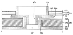
또한, 본 발명은 홀 영역의 하부 커버(150) 돌출부(150b)에 고정 홀(H)을 형성하여 광학시트(143)들을 끼워 고정하는 것을 특징으로 한다. 즉, 본 발명은 하부 커버(150)의 돌출부(150b) 측면에 고정 홀(H)을 형성하고, 이에 대응하는 제 2 홀(143a', 143b', 143c')들 주변의 광학시트(143a, 143b, 143c)들 내측에 돌기(144)를 형성하여 고정 홀(H)에 끼워 고정하는 것을 특징으로 한다.Further, the present invention is characterized in that a fixing hole (H) is formed in a protrusion (150b) of a lower cover (150) of a hole area to fix the optical sheets (143) therebetween. That is, in the present invention, the fixing hole H is formed on the side of the
돌기(144)는 제 2 홀(143a', 143b', 143c')들 주변의 광학시트(143a, 143b, 143c)들 내측에 제 2 홀(143a', 143b', 143c')들의 중심을 향하여 돌출할 수 있다.The
고정 홀(H)과 돌기(144)는 직사각형이나 정사각형의 사각형 형태뿐만 아니라 다른 형태도 가능하며, 돌기(144)가 고정 홀(H)에 고정되기만 하면 고정 홀(H)을 관통할 필요는 없다.The fixing holes H and the
고정 홀(H)과 돌기(144)는 소정영역에 하나씩 형성될 수 있으나, 본 발명이 이에 한정되는 것은 아니다.The fixing hole H and the
고정 홀(H)은 돌기(144)를 포함하는 광학시트(143)들의 총 두께와 동일하거나 더 큰 높이를 가지도록 형성될 수 있다. 고정 홀(H)은 돌기(144)의 폭과 동일하거나 더 큰 폭을 가지도록 형성될 수 있다.The fixing hole H may be formed to have a height equal to or greater than the total thickness of the
이에 의하면, 광학시트(143)들이 X와, Y 및 Z 방향으로 구속됨에 따라 유동 및 탈착이 방지되어 광학시트(143)들의 갈림과 빛샘 및 유동에 의한 노이즈(rattle noise)가 방지되는 효과를 제공한다. 또한, 돌출부(150b)의 고정 홀(H)과 광학시트(143)들의 돌기(144)는 광학시트(143)들을 조립하는데 가이드 역할을 할뿐만 아니라 기존의 광학시트 고정용 몰드를 삭제할 수 있어 약 0.2$의 비용이 절감되는 효과를 제공한다.According to this, since the
전술한 바와 같이 본 발명은 체결부와 돌출부에 나사산을 형성하여 가이드 수단과 하부 커버간 체결을 보다 강화시키는 경우도 가능하며, 이를 다음의 본 발명의 제 2 실시예를 통해 상세히 설명한다.As described above, according to the present invention, it is possible to further strengthen the fastening between the guide means and the lower cover by forming a thread on the fastening portion and the protruding portion, which will be described in detail through the following second embodiment of the present invention.
도 11은 본 발명의 제 2 실시예에 따른 이형 디스플레이의 일부 단면을 개략적으로 보여주는 도면이다.11 is a schematic view showing a partial cross-section of a mold-release display according to a second embodiment of the present invention.
도 12는 본 발명의 제 2 실시예에 따른 이형 디스플레이의 다른 일부 단면을 개략적으로 보여주는 도면이다. 즉, 도 11은 홀 주변의 단면을 예로 들어 보여주고 있으며, 도 12는 가장자리 부분의 단면을 예로 들어 보여주고 있다.12 is a schematic view showing another partial cross-section of a mold-release display according to a second embodiment of the present invention. That is, FIG. 11 shows an example of a section around the hole, and FIG. 12 shows an edge of the edge as an example.
이때, 도 11 및 도 12에 도시된 본 발명의 제 2 실시예에 따른 이형 디스플레이는 가이드 수단과 하부 커버간 체결구조를 제외하고는 전술한 본 발명의 제 1 실시예와 실질적으로 동일한 구성으로 이루어져 있다.11 and 12, the mold release display according to the second embodiment of the present invention has substantially the same structure as that of the first embodiment of the present invention except for the guiding means and the fastening structure between the lower cover have.
그리고, 도 13a 및 도 13b는 도 11에 도시된 본 발명의 제 2 실시예에 따른 하부 커버 및 가이드 수단을 개략적으로 보여주는 단면도이다.13A and 13B are cross-sectional views schematically showing a lower cover and guide means according to a second embodiment of the present invention shown in FIG.
도 11과, 도 12 및 도 13a, 13b를 참조하면, 본 발명의 제 2 실시예에 따른 이형 디스플레이는 컬러필터 기판(205)과 어레이 기판(215) 사이에 액정이 주입되어 영상을 출력하는 액정패널(210)과, 액정패널(210)의 배면에 설치되어 액정패널(210)의 전면에 걸쳐 빛을 방출하는 백라이트 유닛(240) 및 액정패널(210)과 백라이트 유닛(240)을 수납하여 고정하는 하부 커버(250)를 포함하여 구성될 수 있다.11, 12 and 13A and 13B, a display according to a second embodiment of the present invention includes a
전술한 바와 같이 액정패널(210)은 화소들이 매트릭스 형태로 배열되어 영상을 출력하며, 서로 대향하여 균일한 셀 갭이 유지되도록 합착된 컬러필터 기판(205)과, 어레이 기판(215) 및 컬러필터 기판(205)과 어레이 기판(215) 사이의 셀 갭에 형성된 액정층으로 이루어져 있다.As described above, the
컬러필터 기판(205)과 어레이 기판(215)의 외측에는 각각 편광판(201, 211)이 부착되며, 이때 하부 편광판(211)은 백라이트 유닛(240)을 경유한 빛을 편광 시키며, 상부 편광판(201)은 액정패널(210)을 경유한 빛을 편광 시킨다.Polarizing
이때, 컬러필터 기판(205)과 어레이 기판(215)이 합착된 액정패널(210)의 가장자리 측면은 사이드 실링을 통해 실링재(248)로 밀봉될 수 있다. 다만, 본 발명이 이에 한정되는 것은 아니다. 또한, 도 12에 도시된 바와 같이 상부 편광판(201)이 실링재(248)의 일부를 덮도록 부착될 수 있으나, 본 발명이 이에 한정되는 것은 아니다.At this time, the edge side of the
본 발명의 제 2 실시예에 따른 백라이트 유닛(240)을 구체적으로 설명하면, 도광판(242)의 일측에 빛을 발생시키는 광원을 포함하는 광원 유닛(미도시)이 설치되며, 도광판(242)의 배면에는 반사판(241)이 설치될 수 있다.A light source unit (not shown) including a light source for generating light is provided on one side of the
또한, 도광판(242)의 상면에는 도광판(242)으로부터 출사되는 광의 효율을 향상시켜 액정패널(210)에 조사하는 다수의 광학시트(243)들이 배치될 수 있다.A plurality of
다만, 본 발명이 전술한 백라이트 유닛(240)의 구조에 한정되는 것은 아니며, 어떠한 구조의 백라이트 유닛(240)이라도 본 발명에 따른 이형 디스플레이에 적용될 수 있다.However, the present invention is not limited to the structure of the above-described
도광판(242)은 광원으로부터 광을 제공받고, 이 광을 액정패널(210) 측으로 안내한다.The
도광판(242)은 PMMA나 PC의 플라스틱으로 이루어질 수 있다.The
반사판(241)은 하부 커버(250)와 도광판(242)의 배면 사이에 위치한다. 이 반사판(241)은 광원으로부터의 광 및 도광판(242)으로부터의 광을 액정패널(210) 측으로 반사하는 역할을 한다. 이때, 도 11 및 도 12에는 반사판(241)이 도광판(242)의 가장자리 측면을 감싸는 형태로 형성된 경우를 예로 들고 있으나, 본 발명이 이에 한정되는 것은 아니다.The
그리고, 광원은 광을 출사하는 수단으로, 예를 들어 CCFL, HCFL 또는 EEFL이나 LED 중 어느 하나를 선택하여 사용할 수 있으나, 이에 한정되지 않는다. 이하에서는 설명의 편의를 위해 광원으로 LED 어레이를 사용한 경우를 예로 든다.The light source is a means for emitting light, for example, CCFL, HCFL, EEFL or LED, but the present invention is not limited thereto. Hereinafter, an LED array is used as a light source for convenience of explanation.
LED 어레이는 광 출사면이 도광판(242)의 입사면을 바라보도록 연성회로기판에 설치된다. 즉, 광원 유닛은 연성회로기판과 연성회로기판의 일측 면에 실장되는 LED 어레이와 같은 다수의 광원을 포함할 수 있다.The LED array is installed on the flexible circuit board so that the light exit surface faces the incident surface of the
광원은 인버터에 연결되어 전원을 공급받아 빛을 출사할 수 있다.The light source is connected to the inverter and can receive power and emit light.
광원에서 출사된 빛은 투명한 재질의 도광판(242) 측면으로 입사되고, 도광판(242)의 배면에 배치된 반사판(241)은 도광판(242)의 배면으로 투과되는 빛을 도광판(242) 상면의 광학시트(243)들 쪽으로 반사시켜 빛의 손실을 줄이고 균일도를 향상시키게 된다.The light emitted from the light source is incident on the side surface of the
이때, 자세히 도시하지 않았지만, 광학시트(243)들은 확산시트와 프리즘시트를 포함하며, DBEF와 같은 휘도강화 필름 및 보호시트가 추가될 수 있다.At this time, although not shown in detail, the
광학시트(243)들은 도광판(242)의 상면과 액정패널(210)의 후면 사이에 구비될 수 있다.The
이와 같은 구조의 백라이트 유닛(240)은 하부 커버(250) 내에 수납된다.The
하부 커버(250)는 바닥으로부터 수직하게 연장된 다수의 측면부(250a)들을 포함할 수 있다. 측면부(250a)들은 하부 커버(250)의 각 모서리로부터 소정 높이를 갖도록 수직하게 연장될 수 있다. 서로 인접한 측면부(250a)들의 가장자리는 서로 연결될 수 있다.The
각 측면부(250a)들은 이형 디스플레이의 중심을 향해 절곡되어 소정 폭을 가진 안착부(250a')를 구성하며, 안착부(250a')들 위에 액정패널(210)이 안착될 수 있다.Each
측면부(250a)들 및 안착부(250a')들에 의해 둘러싸인 공간은 백라이트 유닛(240)이 수납되는 수납공간을 이룬다. 즉, 측면부(250a)들 및 안착부(250a')들은 하부 커버(250)의 바닥으로부터 'ㄷ'자 형태로 구부러진 것을 알 수 있다. 따라서, 하부 커버(250)의 내부에 반사판(241)과, 도광판(242) 및 광학시트(243)들이 수납되며, 도광판(242) 및 광학시트(243)들은 'ㄷ'자 형태로 구부러진 하부 커버(250)의 측면부(250a)들 및 안착부(250a')들에 의해 하부 커버(250) 내부에 고정될 수 있다.The space surrounded by the
이때, 광원 유닛과 대응되는 하부 커버(250)의 내부 일측에는 다수의 광원과 연성회로기판이 수납되는 수용 홈이 형성될 수 있다.At this time, an accommodating groove for accommodating the plurality of light sources and the flexible circuit board may be formed on the inner side of the
또한, 이와 같은 구조의 백라이트 유닛(240) 상부에는 소정의 차광 테이프(246a, 246b)가 구비될 수 있다.In addition, predetermined
제 1 차광 테이프(246a)는 백라이트 유닛(240)의 광원 유닛과 대응되는 영역과 하부 커버(250)의 가장자리와 대응될 수 있으며, 제 2 차광 테이프(246b)는 제 1 홀 주변의 가이드 수단(245)의 지지부(245c)와 대응될 수 있으며, 액정패널(210)을 하부 커버(250) 및/또는 가이드 수단(245)에 고정하는 역할을 할 수 있다. 다만, 본 발명이 이에 한정되는 것은 아니며, 제 1 차광 테이프(246a) 및/또는 제 2 차광 테이프(246b)를 구비하지 않을 수도 있다.The first light-shielding
또한, 전체가 검정색으로 이루어져 백라이트 유닛(240)으로부터 출사된 광이 외부로 새어나가는 것을 방지하는 역할을 할 수 있다.In addition, the entirety is made of black so that the light emitted from the
이와 같이 구성되는 본 발명의 제 2 실시예에 따른 이형 디스플레이에 있어, 액정패널(210)은 디스플레이 면을 기준으로 이형 디스플레이, 일 예로 차량 계기판의 외곽 형태에 대응되는 형태를 가질 수 있다. 뿐만 아니라, 백라이트 유닛의 기구와 광학부품, 즉 광학시트(243)들, 도광판(242), 반사판(231) 및 하부 커버(250)는 전체가 이형 디스플레이의 외곽 형태에 대응되는 형태를 가질 수 있다. 다만, 본 발명이 이에 한정되는 것은 아니며, 전술한 바와 같이 원형이나 타원형 등의 곡선 형태, 또는 직사각형이나 마름모와 같은 다각의 형태를 가지거나, 또는 여러 형태가 혼합된 형태를 가질 수 있다.In the mold release display according to the second embodiment of the present invention configured as described above, the
또한, 전술한 바와 같이 액정패널(210), 광학시트(243)들, 도광판(242), 반사판(231) 및 하부 커버(250)의 좌, 우측 소정 영역에는 원 형상의 제 1 홀, 제 2 홀들, 제 3 홀, 제 4 홀 및 제 5 홀(250')이 형성될 수 있다. 다만, 본 발명이 이에 한정되는 것은 아니며, 제 1 홀, 제 2 홀들, 제 3 홀, 제 4 홀 및 제 5 홀(250') 역시, 원형이나 타원형 등의 곡선 형태, 또는 직사각형이나 마름모와 같은 다각의 형태를 가지거나, 또는 여러 형태가 혼합된 형태를 가질 수 있다.In the predetermined left and right regions of the
이러한 제 1 홀, 제 2 홀들, 제 3 홀, 제 4 홀 및 제 5 홀(250')은 이형 디스플레이로 차량 계기판을 적용하는 경우, 타코미터와 속도계 등의 바늘이 관통하는 홀이 될 수 있다.The first hole, the second hole, the third hole, the fourth hole and the fifth hole 250 'may be a hole through which a needle such as a tachometer, a speedometer or the like penetrates when a vehicle instrument panel is applied to the mold release display.
액정패널(210)은 실제 디스플레이 시에 제 1 홀을 제외한 영역에서 영상이 디스플레이 될 수 있다.The
일 예로, 제 1 홀은 제 2 홀들과, 제 3 홀 및 제 4 홀보다 더 큰 직경을 가질 수 있으며, 또한 제 2 홀들과, 제 3 홀 및 제 4 홀은 제 5 홀(250')보다 더 큰 직경을 가질 수 있다.For example, the first hole may have a larger diameter than the second holes and the third and fourth holes, and the second holes and the third and fourth holes may have a diameter larger than that of the fifth hole 250 ' It can have a larger diameter.
전술한 바와 같이 하부 커버(250)의 좌, 우측 소정 영역에는 원 형상의 제 5 홀(250')이 형성될 수 있으며, 제 5 홀(250')의 가장자리를 따라 돌출된 돌출부(250b)를 가질 수 있다.As described above, a circular fifth hole 250 'may be formed in predetermined left and right regions of the
돌출부(250b)는 제 5 홀(250')의 가장자리로부터 액정패널(210) 방향으로 돌출된 구조로 이루어지며, 본 발명의 제 2 실시예에 따른 돌출부(250b)의 내측에는 소정의 암 나사산(250b')이 형성될 수 있다. 다만, 본 발명이 이에 한정되는 것은 아니며, 돌출부(250b)의 내측에 수 나사산이 형성될 수 있으며, 또한 돌출부(250b)의 외측에 암 나사산이나 수 나사산이 형성될 수도 있다. 암 나사산(250b')은 돌출부(250b)의 상단으로부터 일정 깊이로 형성될 수 있다.The
돌출부(250b)는 하부 커버(250)의 내부 면을 기준으로 돌출부(250b)의 높이는 반사판(241)과, 도광판(242) 및 광학시트(243)들의 두께를 합친 두께와 동일하거나 더 클 수 있다.The height of the
돌출부(250b)의 측면에는 광학시트(243)들과, 도광판(242) 및 반사판(241)의 제 2 홀들과, 제 3 홀 및 제 4 홀과 대응되는 측면이 접촉하거나, 또는 인접하게 위치할 수 있다. 즉, 하부 커버(250)의 돌출부(250b)는 제 2 홀들과, 제 3 홀 및 제 4 홀을 관통하여 광학시트(243)들과, 도광판(242) 및 반사판(241)을 하부 커버(250) 내에 수납한다.The
그리고, 그 위로 가이드 수단(245)이 위치하는데, 본 발명의 제 2 실시예에 따른 가이드 수단(245)은 기존의 가이드 패널의 역할을 하면서 좌, 우측 홀 영역에만 부분적으로 설치되는 것을 특징으로 한다.The guide means 245 according to the second embodiment of the present invention is partly installed only in the left and right hole regions while acting as a conventional guide panel .
즉, 본 발명은 기존과 같이 디스플레이의 가장자리를 감싸는 사각 틀 형태의 가이드 수단이 아닌, 홀 영역에만 부분적으로 설치된 부분 가이드 수단(245)을 구비하는 것을 특징으로 한다.That is, the present invention is characterized not in a guiding means in the form of a square frame that surrounds the edge of the display as in the prior art, but a part guiding means 245 partially provided only in the hole region.
본 발명의 제 2 실시예에 따른 가이드 수단(245)은 하부 커버(250)의 돌출부(250b), 일 예로 돌출부(250b)에 끼워진 상태로 돌출부(250b) 위에 놓여진다. 따라서, 가이드 수단(245)은 돌출부(250b)에 끼워지는 외측에 돌출부(250b)의 암 나사산(250b')에 대응하는 수 나사산(245b')이 형성될 수 있다.The guide means 245 according to the second embodiment of the present invention is placed on the
가이드 수단(245)은 액정패널(210)을 지지하는 역할을 하는 바, 이를 위해 가이드 수단(245)은 액정패널(210)이 끼워지는 실린더 형태의 몸체(245a)와, 몸체(245a)의 외주면으로부터 바깥방향으로 연장되어 액정패널(210)의 가장자리가 안착되어 지지되는 지지부(245c) 및 지지부(245c)의 내측 가장자리로부터 아래로 연장되어 하부 커버(250)의 돌출부(250b)에 체결되는 체결부(245b)를 포함하여 구성될 수 있다.The guide means 245 serves to support the
몸체(245a)는 실린더 형태를 가지며, 액정패널(210)의 제 1 홀에 끼워질 수 있다.The
지지부(245c)는 납작한 실린더 형태를 가지며, 몸체(245a)의 외주면으로부터 바깥방향으로 소정 폭으로 연장되어 제 1 홀 주변의 액정패널(210)의 가장자리가 안착될 수 있다. 이때, 제 2 접착 테이프(246b)를 통해 액정패널(210), 즉 하부 편광판(211)이 지지부(245c) 위에 안착될 수도 있다.The supporting
그리고, 지지부(245c)의 내측 가장자리는 아래로 연장되어 실린더 형태의 체결부(245b)를 구성하며, 체결부(245b)의 외경과 내경은 몸체(245a)의 외경과 내경에 비해 더 작은 크기를 가질 수 있다.The inner edge of the
이러한 체결부(245b)는 하부 커버(250)의 돌출부(250b)에 끼워져 체결되며, 이에 따라 X와, Y 및 Z 방향으로 구속되는데, 이를 위해 체결부(245b)의 외측에 돌출부(250b)의 암 나사산(250b')에 대응하는 수 나사산(245b')이 형성될 수 있다. 다만, 본 발명이 이에 한정되는 것은 아니며, 전술한 바와 같이 돌출부(250b)의 내측에 수 나사산이 형성될 경우, 체결부(245b)의 외측에는 돌출부(250b)의 수 나사산에 대응하는 암 나사산이 형성될 수 있다. 이 경우 가이드 수단(245)을 회전시키며 체결부(245b)를 하부 커버(250)의 돌출부(250b)에 끼워 체결하게 된다.The
또한, 돌출부(250b)의 외측에 암 나사산이나 수 나사산이 형성될 경우, 체결부(245b)의 내측에는 돌출부(250b)의 암 나사산이나 수 나사산에 각각 대응하는 수 나사산이나 암 나사산이 형성될 수 있다. 이 경우 돌출부(250b)는 체결부(245b)의 내측에 끼워져 체결될 수 있다.When female threads or male threads are formed on the outer side of the
암 나사산(245b')은 체결부(245b)의 하단으로부터 일정 깊이만큼 형성될 수 있다.The
이와 같이 본 발명의 제 2 실시예는 홀 영역에 실린더 형태의 부분 가이드 수단(245)을 적용하는 동시에 나사산(245b', 250b')을 통해 가이드 수단(245)과 하부 커버(250) 사이를 체결함으로써 기존과 같이 하부 커버의 외측에 후크를 형성하거나 가이드 패널을 구비하여 그 측면에 후크를 형성할 필요가 없게된다. 따라서, 1.5mm 이하의 내로우 베젤 구조를 구현할 수 있는 효과를 제공한다.As described above, the second embodiment of the present invention applies the cylinder-shaped part guide means 245 to the hole area and also tightens the guide means 245 and the
또한, 본 발명의 제 2 실시예는 전술한 본 발명의 제 1 실시예와 동일하게 홀 영역의 하부 커버(250) 돌출부(250b)에 고정 홀(H)을 형성하여 광학시트(243)들을 끼워 고정하는 것을 특징으로 한다. 즉, 본 발명의 제 2 실시예는 하부 커버(250)의 돌출부(250b) 측면에 고정 홀(H)을 형성하고, 이에 대응하는 제 2 홀들 주변의 광학시트(243)들 내측에 돌기(244)를 형성하여 고정 홀(H)에 끼워 고정하는 것을 특징으로 한다.The second embodiment of the present invention is similar to the first embodiment of the present invention in that a fixing hole H is formed in the
돌기(244)는 제 2 홀들 주변의 광학시트(243)들 내측에 제 2 홀들의 중심을 향하여 돌출할 수 있다.The
고정 홀(H)과 돌기(244)는 직사각형이나 정사각형의 사각형 형태뿐만 아니라 다른 형태도 가능하며, 돌기(244)가 고정 홀(H)에 고정되기만 하면 고정 홀(H)을 관통할 필요는 없다.The fixing hole H and the
고정 홀(H)과 돌기(244)는 소정영역에 하나씩 형성될 수 있으나, 본 발명이 이에 한정되는 것은 아니다.The fixing holes H and the
고정 홀(H)은 돌기(244)를 포함하는 광학시트(243)들의 총 두께와 동일하거나 더 큰 높이를 가지도록 형성될 수 있다. 고정 홀(H)은 돌기(244)의 폭과 동일하거나 더 큰 폭을 가지도록 형성될 수 있다.The fixing hole H may be formed to have a height equal to or greater than the total thickness of the
이에 의하면, 광학시트(243)들이 X와, Y 및 Z 방향으로 구속됨에 따라 유동 및 탈착이 방지되어 광학시트(243)들의 갈림과 빛샘 및 유동에 의한 노이즈가 방지되는 효과를 제공한다. 또한, 돌출부(250b)의 고정 홀(H)과 광학시트(243)들의 돌기(244)는 광학시트(243)들을 조립하는데 가이드 역할을 할뿐만 아니라 기존의 광학시트 고정용 몰드를 삭제할 수 있어 약 0.2$의 비용이 절감되는 효과를 제공한다.This prevents flow and detachment of the
한편, 전술한 바와 같이 본 발명은 디스플레이 부가 원형인 원형 디스플레이에도 적용 가능하며, 다음의 본 발명의 제 3 실시예를 통해 상세히 설명한다.As described above, the present invention is also applicable to a circular display having a circular display portion, which will be described in detail through the following third embodiment of the present invention.
도 14는 본 발명의 제 3 실시예에 따른 이형 디스플레이를 예로 들어 보여주는 평면도이다.14 is a plan view showing an example of a display according to a third embodiment of the present invention.
그리고, 도 15는 도 14에 도시된 본 발명의 제 3 실시예에 따른 이형 디스플레이의 구조를 개략적으로 보여주는 분해사시도이다.15 is an exploded perspective view schematically showing the structure of a display according to a third embodiment of the present invention shown in FIG.
디스플레이 부가 원형인 이형 디스플레이를 원형 디스플레이라 지칭하며, 여기서 원형이라는 의미는 실질적으로 원형의 형태를 갖는다는 의미를 포함한다.The differential display in which the display section is circular is referred to as a circular display, wherein the meaning of the circle includes a substantially circular shape.
원형 디스플레이가 적용된 웨어러블 와치(wearable watch)는 리얼 원형을 구현한다. TFT 설계에서부터 디스플레이 외부의 베젤 디자인까지 완벽한 원형으로 디자인해 개발되고 있다. 이는 동일 사이즈의 정사각형 디스플레이보다 화면 면적이 57% 이상 넓어진다. 이를 통해 원형 제품은 화면 전체를 디스플레이 해 사용자 편의성을 높일 수 있고, 또한 두께는 얇으면서도 화면 전체 터치가 가능하도록 할 수 있다.A wearable watch with a circular display implements real prototypes. From TFT design to bezel design on the outside of the display, it is being developed as a perfect circular design. This widens the screen area by more than 57% compared to a square display of the same size. Thus, the circular product can display the entire screen to enhance the convenience of the user, and the touch screen can be made thin even though the thickness is thin.
이때, 도 14 및 도 15에 도시된 본 발명의 제 3 실시예에 따른 이형 디스플레이는 웨어러블 와치를 예로 들고 있으나, 본 발명이 이에 한정되는 것은 아니다.14 and 15 illustrate a wearable wristwatch according to a third embodiment of the present invention, the present invention is not limited thereto.
단말기(terminal)는 이동 가능 여부에 따라 이동 단말기(mobile/portable terminal) 및 고정 단말기(stationary terminal)로 나뉠 수 있으며, 웨어러블 와치는 이동 단말기에 속한다. 다시 이동 단말기는 사용자의 직접 휴대 가능 여부에 따라 휴대형 단말기(handheld terminal) 및 거치형 단말기(vehicle mount terminal)로 나뉠 수 있다.A terminal can be divided into a mobile / portable terminal and a stationary terminal depending on whether the terminal is movable, and the wearable watch belongs to a mobile terminal. The mobile terminal can be divided into a handheld terminal and a vehicle mount terminal according to whether the user can directly carry the mobile terminal.
이와 같은 단말기는 기능이 다양화됨에 따라, 예를 들어 사진이나 동영상의 촬영, 음악이나 동영상 파일의 재생, 게임. 방송의 수신 등의 복합적인 기능들을 갖춘 멀티미디어 기기 형태로 구현되고 있다. 나아가 단말기의 기능지지 및 증대를 위해 단말기의 구조적인 부분 및 소프트웨어적인 부분을 개량하는 것이 고려될 수 있다.As the functions of such terminals are diversified, for example, photographing or video shooting, music or video file playback, games. Reception of broadcasts, and the like. Further, it may be considered to improve the structural and software parts of the terminal to support and enhance the functions of the terminal.
이러한 개량에 힘입어 최근 이동 단말기는 다양한 형태의 디자인으로 진화하고 있으며, 사용자의 신체에 고정될 수 있는 웨어러블 와치 타입의 이동 단말기가 개발되고 있다.Recently, mobile terminals have evolved into various types of designs due to such improvements, and wearable watch type mobile terminals that can be fixed to the user's body have been developed.
도 14를 참조하면, 와치 타입의 이동 단말기(300)는 디스플레이 부(360)를 구비하는 본체(361) 및 본체(361)에 연결되어 손목에 착용 가능하도록 구성되는 밴드(362)를 포함할 수 있다.14, a watch-type
본체(361)는 외관을 형성하는 케이스를 포함한다. 케이스는 각종 전자부품들을 수용하는 내부 공간을 마련하는 다수의 케이스를 포함할 수 있다. 다만, 본 발명은 이에 한정되는 것은 아니고, 하나의 케이스가 내부 공간을 마련하도록 구성되어 유니 바디의 이동 단말기(300)가 구현될 수도 있다.The
이와 같은 케이스들은 합성수지를 사출하여 형성되거나, 금속 재질, 예를 들어 스테인레스스틸(STS) 또는 티타늄(Ti) 등과 같은 금속 재질을 갖도록 형성될 수도 있다.Such cases may be formed by injection molding of a synthetic resin, or may be formed of a metal material, for example, a metal material such as stainless steel (STS) or titanium (Ti).
와치 타입의 이동 단말기(300)는 무선 통신이 가능하도록 구성되며, 본체(361)에는 무선 통신을 위한 안테나가 설치될 수 있다. 한편, 안테나는 케이스를 이용하여 그 성능을 확장시킬 수 있다. 예를 들어, 도전성 재질을 포함하는 케이스가 안테나와 전기적으로 연결되어 그라운드 영역 또는 방사 영역을 확장시키도록 구성될 수 있다.The watch-type
본체(361)의 일면에는 디스플레이 부(360)가 노출되게 배치될 수 있다.The
일 예로, 본체(361)의 전면에는 디스플레이 부(360)가 배치되어 정보를 출력할 수 있으며, 디스플레이 부(360)에는 터치센서가 구비되어 터치 스크린으로 구현될 수 있다.For example, the
일 예로, 액정패널에 의해 구현되는 디스플레이 부(360)는 시간을 나타내는 숫자(1 내지 12)가 출력되며, 시간의 흐름에 따라 시에 해당되는 숫자를 가리키는 시침 및 시간의 흐름에 따라 분/초에 해당하는 숫자를 가르치는 분침/초침으로 구성되는 표시침(365)에 의해 현재 시간을 확인할 수 있다.For example, the
본체(361)에는 음향 출력부, 카메라, 마이크로폰, 사용자 입력부 등이 구비될 수 있다. 디스플레이 부(360)가 터치 스크린으로 구현되는 경우, 사용자 입력부로 기능할 수 있으며, 이에 따라 본체(361)에 별도의 키가 구비되지 않을 수 있다.The
밴드(362)는 손목에 착용되어 손목을 감싸도록 이루어지며, 착용이 용이하도록 플렉서블 재질로 형성될 수 있다. 그러한 예로서, 밴드(362)는 가죽, 고무, 실리콘, 합성수지 재질 등으로 형성될 수 있다. 또한, 밴드(362)는 본체(361)에 착탈 가능하게 구성되어, 사용자가 취향에 따라 다양한 형태의 밴드로 교체 가능하게 구성 될 수 있다.The
한편, 밴드(362)는 안테나의 성능을 확장시키는 데에 이용될 수 있다. 예를 들어, 밴드에는 안테나와 전기적으로 연결되어 그라운드 영역을 확장시키는 그라운드 확장부가 내장될 수 있다.On the other hand, the
밴드(362)에는 파스너(fastener)가 구비될 수 있다. 파스너는 버클(buckle), 스냅-핏(snap-fit)이 가능한 후크 구조, 또는 벌크로(velcro; 상표명) 등에 의하여 구현될 수 있으며, 신축성이 있는 구간 또는 재질을 포함할 수 있다.The
이상에서와 같은 본 발명의 제 3 실시예에 따른 이형 디스플레이는 디스플레이 부를 기준으로 도넛 형태의 구조로 이루어져 도넛 형태의 영역을 디스플레이하기 위한 전자기기에 이용될 수 있다.As described above, the mold release display according to the third embodiment of the present invention can be used for an electronic device for displaying a donut-shaped area having a donut-shaped structure based on a display unit.
일 예로, 본 발명의 이형 디스플레이는 웨어러블 워치에 적용될 수 있다. 여기서, 시계의 시침과, 분침 및 초침 등의 기구물들은 홀을 관통하여 액정패널의 상부 면에 위치할 수 있다.As an example, the mold release display of the present invention can be applied to a wearable watch. Here, the hour, minute, second, and other mechanisms of the watch may be positioned on the upper surface of the liquid crystal panel through the holes.
즉, 본 발명의 이형 디스플레이는 전체가 원 형상의 구조를 가지며, 기구물이 관통될 수 있도록 홀이 형성되어 워치 등과 같은 도넛 형태의 영역을 디스플레이하기 위한 전자기기에 적용될 수 있다.That is, the mold-release display of the present invention has a circular structure as a whole and can be applied to an electronic device for displaying a donut-shaped area such as a watch or the like by forming a hole so that an instrument can be penetrated.
도 15를 참조하면, 본 발명의 제 3 실시예에 따른 이형 디스플레이는 컬러필터 기판(305)과 어레이 기판(315) 사이에 액정이 주입되어 영상을 출력하는 액정패널(310)과, 액정패널(310)의 배면에 설치되어 액정패널(310)의 전면에 걸쳐 빛을 방출하는 백라이트 유닛 및 액정패널(310)과 백라이트 유닛을 수납하여 고정하는 하부 커버(350)를 포함하여 구성될 수 있다.15, a mold release display according to a third embodiment of the present invention includes a
전술한 바와 같이 액정패널(310)은 화소들이 매트릭스 형태로 배열되어 영상을 출력하며, 서로 대향하여 균일한 셀 갭이 유지되도록 합착된 컬러필터 기판(305)과, 어레이 기판(315) 및 컬러필터 기판(305)과 어레이 기판(315) 사이의 셀 갭에 형성된 액정층으로 이루어져 있다.As described above, the
본 발명의 제 3 실시예에 따른 백라이트 유닛을 구체적으로 설명하면, 도광판(342)의 일측에 빛을 발생시키는 광원을 포함하는 광원 유닛(미도시)이 설치되며, 도광판(342)의 배면에는 반사판(341)이 설치될 수 있다.A light source unit (not shown) including a light source for generating light is provided on one side of the
또한, 도광판(342)의 상면에는 도광판(342)으로부터 출사되는 광의 효율을 향상시켜 액정패널(310)에 조사하는 다수의 광학시트(343)들이 배치될 수 있다.A plurality of
다만, 본 발명이 전술한 백라이트 유닛의 구조에 한정되는 것은 아니며, 어떠한 구조의 백라이트 유닛이라도 본 발명에 따른 이형 디스플레이에 적용될 수 있다.However, the present invention is not limited to the structure of the above-described backlight unit, and any backlight unit of any structure can be applied to the display of the present invention.
도광판(342)은 광원으로부터 광을 제공받고, 이 광을 액정패널(310) 측으로 안내한다.The
도광판(342)은 PMMA나 PC의 플라스틱으로 이루어질 수 있다.The
반사판(341)은 하부 커버(350)와 도광판(342)의 배면 사이에 위치한다. 이 반사판(341)은 광원으로부터의 광 및 도광판(342)으로부터의 광을 액정패널(310) 측으로 반사하는 역할을 한다.The
광원에서 출사된 빛은 투명한 재질의 도광판(342) 측면으로 입사되고, 도광판(342)의 배면에 배치된 반사판(341)은 도광판(342)의 배면으로 투과되는 빛을 도광판(342) 상면의 광학시트(343)들 쪽으로 반사시켜 빛의 손실을 줄이고 균일도를 향상시키게 된다.The light emitted from the light source is incident on the side surface of the
이때, 광학시트(343)들은 확산시트(343a)와 프리즘시트(343b)를 포함하며, DBEF와 같은 휘도강화 필름(343c) 및 보호시트가 추가될 수 있다.At this time, the
광학시트(343)들은 도광판(342)의 상면과 액정패널(310)의 후면 사이에 구비될 수 있다.The
이와 같은 구조의 백라이트 유닛은 하부 커버(350) 내에 수납된다.The backlight unit having such a structure is accommodated in the
하부 커버(350)는 바닥으로부터 수직하게 연장된 다수의 측면부(350a)들을 포함할 수 있다. 측면부(350a)들은 하부 커버(350)의 가장자리로부터 소정 높이를 갖도록 수직하게 연장될 수 있다.The
측면부(350a)는 이형 디스플레이의 중심을 향해 절곡되어 소정 폭을 가진 안착부(350a')를 구성하며, 안착부(350a') 위에 액정패널(310)이 안착될 수 있다.The
측면부(350a) 및 안착부(350a')에 의해 둘러싸인 공간은 백라이트 유닛이 수납되는 수납공간을 이룬다. 즉, 측면부(350a) 및 안착부(350a')는 하부 커버(350)의 바닥으로부터 'ㄷ'자 형태로 구부러진 것을 알 수 있다. 따라서, 하부 커버(350)의 내부에 반사판(341)과, 도광판(342) 및 광학시트(343)들이 수납되며, 도광판(342) 및 광학시트(343)들은 'ㄷ'자 형태로 구부러진 하부 커버(350)의 측면부(350a) 및 안착부(350a')에 의해 하부 커버(350) 내부에 고정될 수 있다.The space enclosed by the
이때, 광원 유닛과 대응되는 하부 커버(350)의 일측에는 다수의 광원과 연성회로기판이 수납되는 수용 부(351)가 형성될 수 있다.At this time, a receiving
이와 같이 구성되는 본 발명의 제 3 실시예에 따른 이형 디스플레이에 있어, 액정패널(310)은 디스플레이 면을 기준으로 원형 디스플레이, 일 예로 웨어러블 워치의 외곽 형태에 대응되는 원 형상을 가질 수 있다. 뿐만 아니라, 백라이트 유닛의 기구와 광학부품, 즉 광학시트(343)들, 도광판(342), 반사판(331) 및 하부 커버(350)는 전체가 이형 디스플레이의 외곽 형태에 대응되는 원 형상을 가질 수 있다. 다만, 본 발명이 이에 한정되는 것은 아니다.In the mold release display according to the third embodiment of the present invention configured as described above, the
또한, 전술한 바와 같이 액정패널(310), 광학시트(343)들, 도광판(342), 반사판(331) 및 하부 커버(350)의 중앙에는 원 형상의 제 1 홀(310'), 제 2 홀(343a', 343b', 343c')들, 제 3 홀(342'), 제 4 홀(341') 및 제 5 홀(350')이 형성될 수 있다. 다만, 본 발명이 이에 한정되는 것은 아니다.As described above, in the center of the
이러한 제 1 홀(310'), 제 2 홀(343a', 343b', 343c')들, 제 3 홀(342'), 제 4 홀(341') 및 제 5 홀(350')은 이형 디스플레이로 웨어러블 워치를 적용하는 경우, 시침과, 분침 및 초침 등의 표시침이 관통하는 홀이 될 수 있다.The first hole 310 ', the
액정패널(310)은 실제 디스플레이 시에 제 1 홀(310')을 제외한 영역에서 영상이 디스플레이 될 수 있다.The
일 예로, 제 1 홀(310')은 제 2 홀(343a', 343b', 343c')들과, 제 3 홀(342') 및 제 4 홀(341')보다 더 큰 직경을 가질 수 있으며, 또한 제 2 홀(343a', 343b', 343c')들과, 제 3 홀(342') 및 제 4 홀(341')은 제 5 홀(350')보다 더 큰 직경을 가질 수 있다.For example, the first hole 310 'may have a larger diameter than the
전술한 바와 같이 하부 커버(350)의 중앙에는 원 형상의 제 5 홀(350')이 형성될 수 있으며, 제 5 홀(350')의 가장자리를 따라 돌출된 돌출부(350b)를 가질 수 있다.As described above, a circular fifth hole 350 'may be formed in the center of the
돌출부(350b)는 제 5 홀(350')의 가장자리로부터 액정패널(310) 방향으로 돌출된 구조로 이루어지며, 본 발명의 제 3 실시예에 따른 돌출부(350b)의 내측에는 소정의 암 나사산(350b')이 형성될 수 있다. 다만, 본 발명이 이에 한정되는 것은 아니며, 돌출부(350b)의 내측에 수 나사산이 형성될 수 있으며, 또한 돌출부(350b)의 외측에 암 나사산이나 수 나사산이 형성될 수도 있다. 물론 본 발명은 전술한 본 발명의 제 1 실시예처럼, 돌출부(350b)의 내측이나 외측에 어떠한 나사산이 형성되지 않은 경우에도 적용 가능하다. 암 나사산(350b')은 돌출부(350b)의 상단으로부터 일정 깊이로 형성될 수 있다.The
돌출부(350b)는 하부 커버(350)의 내부 면을 기준으로 돌출부(350b)의 높이는 반사판(341)과, 도광판(342) 및 광학시트(343)들의 두께를 합친 두께와 동일하거나 더 클 수 있다.The
돌출부(350b)의 측면에는 광학시트(343a, 343b, 343c)들과, 도광판(342) 및 반사판(341)의 제 2 홀(343a', 343b', 343c')들과, 제 3 홀(342') 및 제 4 홀(341')과 대응되는 측면이 접촉하거나, 또는 인접하게 위치할 수 있다. 즉, 하부 커버(350)의 돌출부(350b)는 제 2 홀(343a', 343b', 343c')들과, 제 3 홀(342') 및 제 4 홀(341')을 관통하여 광학시트(343a, 343b, 343c)들과, 도광판(342) 및 반사판(341)을 하부 커버(350) 내에 수납한다.The
그리고, 그 위로 가이드 수단(345)이 위치하는데, 본 발명의 제 3 실시예에 따른 가이드 수단(345)은 중앙에만 부분적으로 설치되는 것을 특징으로 한다.The guide means 345 according to the third embodiment of the present invention is characterized in that the guide means 345 is partially installed only at the center.
본 발명의 제 3 실시예에 따른 가이드 수단(345)은 하부 커버(350)의 돌출부(350b), 일 예로 돌출부(350b)의 제 5 홀(350')에 끼워진 상태로 돌출부(350b) 위에 놓여진다. 따라서, 가이드 수단(345)은 돌출부(350b)에 끼워지는 외측에 돌출부(350b)의 암 나사산에 대응하는 수 나사산이 형성될 수 있다.The guide means 345 according to the third embodiment of the present invention is placed on the protruding
자세히 도시하지 않았지만, 전술한 본 발명의 제 1, 제 2 실시예와 실질적으로 동일하게 가이드 수단(345)은 액정패널(310)을 지지하는 역할을 하는 바, 이를 위해 가이드 수단(345)은 액정패널(310)이 끼워지는 실린더 형태의 몸체와, 몸체의 외주면으로부터 바깥방향으로 연장되어 액정패널(310)의 가장자리가 안착되어 지지되는 지지부 및 지지부의 내측 가장자리로부터 아래로 연장되어 하부 커버(350)의 돌출부(350b)에 체결되는 체결부를 포함하여 구성될 수 있다.Although not shown in detail, the guide means 345 serves to support the
또한, 본 발명의 제 3 실시예는 전술한 본 발명의 제 1, 제 2 실시예와 동일하게 홀 영역의 하부 커버(350) 돌출부(350b)에 고정 홀(H)을 형성하여 광학시트(343)들을 끼워 고정하는 것을 특징으로 한다. 즉, 본 발명의 제 3 실시예는 하부 커버(350)의 돌출부(350b) 측면에 고정 홀(H)을 형성하고, 이에 대응하는 제 2 홀(343a', 343b', 343c')들 주변의 광학시트(343a, 343b, 343c)들 내측에 돌기(344)를 형성하여 고정 홀(H)에 끼워 고정하는 것을 특징으로 한다.The third embodiment of the present invention is similar to the first and second embodiments of the present invention in that the fixing hole H is formed in the projecting
돌기(344)는 제 2 홀(343a', 343b', 343c')들 주변의 광학시트(343a, 343b, 343c)들 내측에 제 2 홀(343a', 343b', 343c')들의 중심을 향하여 돌출할 수 있다.The
고정 홀(H)과 돌기(344)는 직사각형이나 정사각형의 사각형 형태뿐만 아니라 다른 형태도 가능하며, 돌기(344)가 고정 홀(H)에 고정되기만 하면 고정 홀(H)을 관통할 필요는 없다.The fixing hole H and the
고정 홀(H)과 돌기(344)는 소정영역에 하나씩 형성될 수 있으나, 본 발명이 이에 한정되는 것은 아니다.The fixing hole H and the
고정 홀(H)은 돌기(344)를 포함하는 광학시트(343)들의 총 두께와 동일하거나 더 큰 높이를 가지도록 형성될 수 있다. 고정 홀(H)은 돌기(344)의 폭과 동일하거나 더 큰 폭을 가지도록 형성될 수 있다.The fixing hole H may be formed to have a height equal to or greater than the total thickness of the
상기한 설명에 많은 사항이 구체적으로 기재되어 있으나 이것은 발명의 범위를 한정하는 것이라기보다 바람직한 실시예의 예시로서 해석되어야 한다. 따라서 발명은 설명된 실시예에 의하여 정할 것이 아니고 특허청구범위와 특허청구범위에 균등한 것에 의하여 정하여져야 한다.While a great many are described in the foregoing description, it should be construed as an example of preferred embodiments rather than limiting the scope of the invention. Therefore, the invention should not be construed as limited to the embodiments described, but should be determined by equivalents to the appended claims and the claims.
110,210,310 : 액정패널 110',310' : 제 1 홀
141,241,341 : 반사판 141',341' : 제 4 홀
142,242,342 : 도광판 142',342' : 제 3 홀
143,243,343 : 광학시트
143a',343a', 143b',343b', 143c',343c' : 제 2 홀
144,244,344 : 돌기 145,245,345 : 가이드 수단
145a,245a : 몸체 145b,245b : 체결부
145c,245c : 지지부 150,250,350 : 하부 커버
150',250',350' : 제 5 홀 150a,250a,350a : 측면부
150a',250a',350a' : 안착부 150b,250b,350b : 돌출부
H : 고정 홀110, 210, 310: liquid crystal panel 110 ', 310': first hole
141, 241, 341: reflector 141 ', 341': fourth hole
142, 242, 342: light guide plate 142 ', 342': third hole
143, 243, 343:
143a ', 343a', 143b ', 343b', 143c ', and 343c'
144, 244, 344:
145a, 245a:
145c and 245c:
150 ', 250', 350 ':
150a ', 250a', 350a ': seating
H: Fixing hole
Claims (15)
상기 액정패널과 상기 백라이트 유닛을 수납하는 하부 커버;
상기 액정패널과, 상기 광학시트 및 상기 하부 커버의 소정 영역에 구비되어 기구물이 관통하는 적어도 하나의 홀; 및
상기 액정패널과 상기 하부 커버 사이의 상기 홀에 구비되어 상기 하부 커버에 체결되는 가이드 수단을 포함하며,
상기 하부 커버는 상기 홀을 통해 상기 액정패널 방향으로 돌출한 돌출부를 구비하여,
상기 돌출부의 측면에 구비된 고정 홀에 상기 광학시트의 내측에 구비된 돌기가 끼워져 고정되는 이형 디스플레이.A backlight unit disposed under the liquid crystal panel and including an optical sheet;
A lower cover for accommodating the liquid crystal panel and the backlight unit;
At least one hole provided in a predetermined region of the optical sheet and the lower cover and through which the instrument passes; And
And guiding means provided in the hole between the liquid crystal panel and the lower cover and fastened to the lower cover,
Wherein the lower cover has a protrusion protruding in the direction of the liquid crystal panel through the hole,
And a protrusion provided on the inner side of the optical sheet is fitted and fixed to a fixing hole provided on a side surface of the protrusion.
도광판의 일측에 위치하는 광원 유닛;
상기 도광판의 배면에 배치되는 반사판; 및
상기 도광판의 상면에 배치되는 상기 광학시트를 포함하여 구성되는 이형 디스플레이.The backlight unit according to claim 1,
A light source unit located at one side of the light guide plate;
A reflection plate disposed on a back surface of the light guide plate; And
And the optical sheet disposed on the upper surface of the light guide plate.
상기 액정패널에 구비된 제 1 홀;
상기 광학시트에 구비된 제 2 홀;
상기 도광판에 구비된 제 3 홀;
상기 반사판에 구비된 제 4 홀; 및
상기 하부 커버에 구비된 제 5 홀을 포함하는 이형 디스플레이.3. The apparatus of claim 2,
A first hole provided in the liquid crystal panel;
A second hole provided in the optical sheet;
A third hole provided in the light guide plate;
A fourth hole provided in the reflection plate; And
And a fifth hole provided in the lower cover.
상기 제 1 홀을 통해 상기 액정패널이 끼워지는 실린더 형태의 몸체;
상기 몸체의 외주면으로부터 바깥방향으로 연장되어 상기 제 1 홀 주변의 상기 액정패널의 가장자리가 안착되는 지지부; 및
상기 지지부의 내측 가장자리로부터 아래로 연장되어 상기 하부 커버의 돌출부에 체결되는 체결부를 포함하여 구성되는 이형 디스플레이.5. The apparatus according to claim 4,
A cylinder-shaped body into which the liquid crystal panel is inserted through the first hole;
A supporting portion extending outwardly from an outer circumferential surface of the body and having an edge of the liquid crystal panel around the first hole; And
And a fastening portion extending downward from an inner edge of the support portion and fastened to a protrusion of the lower cover.
Priority Applications (6)
| Application Number | Priority Date | Filing Date | Title |
|---|---|---|---|
| KR1020150169191A KR101702589B1 (en) | 2015-11-30 | 2015-11-30 | Different form of display device having hole |
| US15/280,318 US10371973B2 (en) | 2015-11-30 | 2016-09-29 | Irregular shape display device having hole |
| DE102016123028.6A DE102016123028B4 (en) | 2015-11-30 | 2016-11-29 | Display device with hole |
| JP2016231967A JP6441884B2 (en) | 2015-11-30 | 2016-11-30 | display |
| CN201611087479.2A CN106873214B (en) | 2015-11-30 | 2016-11-30 | display screen |
| GB1620262.4A GB2544896B (en) | 2015-11-30 | 2016-11-30 | Display device having hole |
Applications Claiming Priority (1)
| Application Number | Priority Date | Filing Date | Title |
|---|---|---|---|
| KR1020150169191A KR101702589B1 (en) | 2015-11-30 | 2015-11-30 | Different form of display device having hole |
Publications (1)
| Publication Number | Publication Date |
|---|---|
| KR101702589B1 true KR101702589B1 (en) | 2017-02-03 |
Family
ID=58073327
Family Applications (1)
| Application Number | Title | Priority Date | Filing Date |
|---|---|---|---|
| KR1020150169191A Active KR101702589B1 (en) | 2015-11-30 | 2015-11-30 | Different form of display device having hole |
Country Status (6)
| Country | Link |
|---|---|
| US (1) | US10371973B2 (en) |
| JP (1) | JP6441884B2 (en) |
| KR (1) | KR101702589B1 (en) |
| CN (1) | CN106873214B (en) |
| DE (1) | DE102016123028B4 (en) |
| GB (1) | GB2544896B (en) |
Cited By (1)
| Publication number | Priority date | Publication date | Assignee | Title |
|---|---|---|---|---|
| US11329116B2 (en) | 2018-11-29 | 2022-05-10 | Samsung Display Co., Ltd. | Display device and manufacturing method thereof |
Families Citing this family (16)
| Publication number | Priority date | Publication date | Assignee | Title |
|---|---|---|---|---|
| WO2015178299A1 (en) * | 2014-05-23 | 2015-11-26 | シャープ株式会社 | Illumination device and display device |
| JP6619619B2 (en) | 2015-11-04 | 2019-12-11 | 日東電工株式会社 | Polarizer, polarizing plate, and method for producing polarizer |
| CN108802891B (en) * | 2018-05-11 | 2020-10-02 | 深圳市帝显电子有限公司 | Instrument panel |
| CN108614320B (en) * | 2018-05-11 | 2020-08-11 | 深圳市帝显电子有限公司 | Vehicle-mounted display |
| CN108761625B (en) * | 2018-05-11 | 2020-08-11 | 深圳市帝显电子有限公司 | Light guide plate and backlight module |
| JP7240111B2 (en) * | 2018-08-09 | 2023-03-15 | Tianma Japan株式会社 | Display device |
| US11366348B2 (en) | 2018-08-27 | 2022-06-21 | Lg Display Co., Ltd. | Display device |
| KR102672833B1 (en) | 2018-08-27 | 2024-06-05 | 엘지디스플레이 주식회사 | Display device |
| DE102018215988A1 (en) * | 2018-09-19 | 2020-03-19 | Volkswagen Aktiengesellschaft | Light module, in particular for use in a lighting device for a motor vehicle |
| JP7257821B2 (en) * | 2019-03-11 | 2023-04-14 | 株式会社ジャパンディスプレイ | electro-optical devices and electronics |
| CN111929934A (en) * | 2019-05-13 | 2020-11-13 | 鸿富泰精密电子(烟台)有限公司 | Liquid crystal display module and manufacturing method thereof |
| CN111007679A (en) * | 2019-10-31 | 2020-04-14 | 深圳市德仓科技有限公司 | Backlight module frame, backlight module and terminal |
| KR102362710B1 (en) * | 2020-05-22 | 2022-02-14 | 주식회사 토비스 | Light guide panel and display module with transmission part, and game unit with the same |
| JP7419321B2 (en) * | 2021-10-11 | 2024-01-22 | 矢崎総業株式会社 | display device |
| US12292633B2 (en) | 2022-05-10 | 2025-05-06 | Beijing Boe Display Technology Co., Ltd. | Display device |
| KR20240068408A (en) * | 2022-11-10 | 2024-05-17 | 엘지디스플레이 주식회사 | Display apparatus |
Citations (3)
| Publication number | Priority date | Publication date | Assignee | Title |
|---|---|---|---|---|
| KR20100038921A (en) * | 2008-10-07 | 2010-04-15 | 엘지디스플레이 주식회사 | Backlight unit and liquid crystal display device having the same |
| JP2014191114A (en) * | 2013-03-26 | 2014-10-06 | Japan Display Inc | Display device, electronic equipment, and manufacturing method of display device |
| WO2015029704A1 (en) * | 2013-08-29 | 2015-03-05 | シャープ株式会社 | Display panel |
Family Cites Families (17)
| Publication number | Priority date | Publication date | Assignee | Title |
|---|---|---|---|---|
| JP2001249324A (en) | 2000-03-03 | 2001-09-14 | Hitachi Ltd | Liquid crystal display |
| CN101331357B (en) | 2005-12-27 | 2010-09-08 | 昭和电工株式会社 | Planar light source device and display device |
| DE102006029219A1 (en) * | 2006-06-26 | 2007-12-27 | Robert Bosch Gmbh | Display instrument for use in motor vehicle, has transparent disk with reduction unit for reducing light transmission through transparent disk, where transparent disk is arranged in inner side of rear wall, cover plate and tube body |
| JP4939893B2 (en) | 2006-10-13 | 2012-05-30 | 株式会社 日立ディスプレイズ | Liquid crystal display |
| US7740394B2 (en) * | 2007-11-08 | 2010-06-22 | Entire Technology Co., Ltd. | Backlight module having two optical sheets |
| CN101266361B (en) * | 2008-04-30 | 2011-05-25 | 友达光电(上海)有限公司 | Backlight module and its frame and fixing elements |
| US20110134342A1 (en) * | 2008-07-24 | 2011-06-09 | Sharp Kabushiki Kaisha | Lighting device, display device and television receiver |
| WO2010044314A1 (en) * | 2008-10-14 | 2010-04-22 | シャープ株式会社 | Support unit, backlight unit, display device, and television receiver |
| WO2013018619A1 (en) | 2011-08-02 | 2013-02-07 | シャープ株式会社 | Lcd panel, electronic device, and method for producing lcd panel |
| US20130215356A1 (en) * | 2012-02-16 | 2013-08-22 | Yajun Yu | Connecting Piece for Backlight Module, Backlight Module and LCD Device |
| US9042105B2 (en) * | 2012-06-21 | 2015-05-26 | Apple Inc. | Electronic devices with printed circuit boards having padded openings |
| CN202647452U (en) * | 2012-06-27 | 2013-01-02 | Tcl光电科技(惠州)有限公司 | Direct type backlight module and liquid crystal display device |
| KR101630342B1 (en) * | 2012-09-28 | 2016-06-14 | 엘지디스플레이 주식회사 | Liquid crystal display device and mathod for manufacturing the same |
| JP2014153483A (en) * | 2013-02-06 | 2014-08-25 | Japan Display Inc | Display device and electronic apparatus |
| CN103969893A (en) * | 2014-05-15 | 2014-08-06 | 友达光电股份有限公司 | A partition device and a direct-lit backlight module comprising the same |
| WO2015178299A1 (en) | 2014-05-23 | 2015-11-26 | シャープ株式会社 | Illumination device and display device |
| JP6054583B2 (en) | 2014-05-23 | 2016-12-27 | シャープ株式会社 | Lighting device and display device |
-
2015
- 2015-11-30 KR KR1020150169191A patent/KR101702589B1/en active Active
-
2016
- 2016-09-29 US US15/280,318 patent/US10371973B2/en active Active
- 2016-11-29 DE DE102016123028.6A patent/DE102016123028B4/en active Active
- 2016-11-30 JP JP2016231967A patent/JP6441884B2/en active Active
- 2016-11-30 CN CN201611087479.2A patent/CN106873214B/en active Active
- 2016-11-30 GB GB1620262.4A patent/GB2544896B/en active Active
Patent Citations (3)
| Publication number | Priority date | Publication date | Assignee | Title |
|---|---|---|---|---|
| KR20100038921A (en) * | 2008-10-07 | 2010-04-15 | 엘지디스플레이 주식회사 | Backlight unit and liquid crystal display device having the same |
| JP2014191114A (en) * | 2013-03-26 | 2014-10-06 | Japan Display Inc | Display device, electronic equipment, and manufacturing method of display device |
| WO2015029704A1 (en) * | 2013-08-29 | 2015-03-05 | シャープ株式会社 | Display panel |
Cited By (2)
| Publication number | Priority date | Publication date | Assignee | Title |
|---|---|---|---|---|
| US11329116B2 (en) | 2018-11-29 | 2022-05-10 | Samsung Display Co., Ltd. | Display device and manufacturing method thereof |
| US11765934B2 (en) | 2018-11-29 | 2023-09-19 | Samsung Display Co., Ltd. | Display device and manufacturing method thereof |
Also Published As
| Publication number | Publication date |
|---|---|
| CN106873214A (en) | 2017-06-20 |
| GB2544896B (en) | 2020-05-27 |
| DE102016123028A1 (en) | 2017-06-01 |
| US10371973B2 (en) | 2019-08-06 |
| JP6441884B2 (en) | 2018-12-19 |
| CN106873214B (en) | 2020-07-24 |
| GB201620262D0 (en) | 2017-01-11 |
| US20170153485A1 (en) | 2017-06-01 |
| DE102016123028B4 (en) | 2020-11-26 |
| JP2017102451A (en) | 2017-06-08 |
| GB2544896A (en) | 2017-05-31 |
Similar Documents
| Publication | Publication Date | Title |
|---|---|---|
| KR101702589B1 (en) | Different form of display device having hole | |
| KR101786884B1 (en) | Different form of display device having hole | |
| KR101717655B1 (en) | Different form of display device having hole | |
| EP2746841B1 (en) | Liquid crystal display device | |
| KR101385204B1 (en) | Backlight assembly and liquid crystal display having the same | |
| US8704964B2 (en) | Liquid crystal display device | |
| US10048524B2 (en) | Top case having outsert molding member and display device having the same | |
| KR102459047B1 (en) | Liquid crystal display device attached touch panel | |
| US20080080209A1 (en) | Lamp assembly, backlight assembly including the same and liquid crystal display including the backlight assembly | |
| KR101782018B1 (en) | Display device | |
| US20050140850A1 (en) | Edge backlight module and liquid crystal display utilizing the same | |
| KR101716393B1 (en) | Display divce | |
| KR101333267B1 (en) | Liquid crystal display device | |
| KR20190068877A (en) | Liquid Crystal Display device | |
| US10620473B2 (en) | Display device | |
| KR20080068414A (en) | Liquid crystal display and manufacturing method thereof | |
| KR102262569B1 (en) | Backlight Unit and Liquid Crystal Display Device having the same | |
| KR102243943B1 (en) | Backlight Unit and Liquid Crystal Display Device having the same | |
| KR101808562B1 (en) | Light guide plate and liquid crystal display device |
Legal Events
| Date | Code | Title | Description |
|---|---|---|---|
| A201 | Request for examination | ||
| PA0109 | Patent application |
Patent event code: PA01091R01D Comment text: Patent Application Patent event date: 20151130 |
|
| PA0201 | Request for examination | ||
| PE0902 | Notice of grounds for rejection |
Comment text: Notification of reason for refusal Patent event date: 20160923 Patent event code: PE09021S01D |
|
| PE0701 | Decision of registration |
Patent event code: PE07011S01D Comment text: Decision to Grant Registration Patent event date: 20170124 |
|
| PR0701 | Registration of establishment |
Comment text: Registration of Establishment Patent event date: 20170126 Patent event code: PR07011E01D |
|
| PR1002 | Payment of registration fee |
Payment date: 20170131 End annual number: 3 Start annual number: 1 |
|
| PG1601 | Publication of registration | ||
| FPAY | Annual fee payment |
Payment date: 20191212 Year of fee payment: 4 |
|
| PR1001 | Payment of annual fee |
Payment date: 20191212 Start annual number: 4 End annual number: 4 |
|
| PR1001 | Payment of annual fee |
Payment date: 20201222 Start annual number: 5 End annual number: 5 |
|
| PR1001 | Payment of annual fee |
Payment date: 20211216 Start annual number: 6 End annual number: 6 |
|
| PR1001 | Payment of annual fee |
Payment date: 20241216 Start annual number: 9 End annual number: 9 |