KR101687977B1 - Interspinous process implant and fusion cage spacer - Google Patents
Interspinous process implant and fusion cage spacer Download PDFInfo
- Publication number
- KR101687977B1 KR101687977B1 KR1020117024039A KR20117024039A KR101687977B1 KR 101687977 B1 KR101687977 B1 KR 101687977B1 KR 1020117024039 A KR1020117024039 A KR 1020117024039A KR 20117024039 A KR20117024039 A KR 20117024039A KR 101687977 B1 KR101687977 B1 KR 101687977B1
- Authority
- KR
- South Korea
- Prior art keywords
- implant
- adjacent
- anchor
- distal
- proximal
- Prior art date
- Legal status (The legal status is an assumption and is not a legal conclusion. Google has not performed a legal analysis and makes no representation as to the accuracy of the status listed.)
- Active
Links
Images


Classifications
-
- A—HUMAN NECESSITIES
- A61—MEDICAL OR VETERINARY SCIENCE; HYGIENE
- A61B—DIAGNOSIS; SURGERY; IDENTIFICATION
- A61B17/00—Surgical instruments, devices or methods
- A61B17/56—Surgical instruments or methods for treatment of bones or joints; Devices specially adapted therefor
- A61B17/58—Surgical instruments or methods for treatment of bones or joints; Devices specially adapted therefor for osteosynthesis, e.g. bone plates, screws or setting implements
- A61B17/68—Internal fixation devices, including fasteners and spinal fixators, even if a part thereof projects from the skin
- A61B17/70—Spinal positioners or stabilisers, e.g. stabilisers comprising fluid filler in an implant
- A61B17/7071—Implants for expanding or repairing the vertebral arch or wedged between laminae or pedicles; Tools therefor
-
- A—HUMAN NECESSITIES
- A61—MEDICAL OR VETERINARY SCIENCE; HYGIENE
- A61B—DIAGNOSIS; SURGERY; IDENTIFICATION
- A61B17/00—Surgical instruments, devices or methods
- A61B17/00234—Surgical instruments, devices or methods for minimally invasive surgery
-
- A—HUMAN NECESSITIES
- A61—MEDICAL OR VETERINARY SCIENCE; HYGIENE
- A61B—DIAGNOSIS; SURGERY; IDENTIFICATION
- A61B17/00—Surgical instruments, devices or methods
- A61B17/56—Surgical instruments or methods for treatment of bones or joints; Devices specially adapted therefor
- A61B17/58—Surgical instruments or methods for treatment of bones or joints; Devices specially adapted therefor for osteosynthesis, e.g. bone plates, screws or setting implements
- A61B17/68—Internal fixation devices, including fasteners and spinal fixators, even if a part thereof projects from the skin
- A61B17/70—Spinal positioners or stabilisers, e.g. stabilisers comprising fluid filler in an implant
- A61B17/7062—Devices acting on, attached to, or simulating the effect of, vertebral processes, vertebral facets or ribs ; Tools for such devices
- A61B17/7065—Devices with changeable shape, e.g. collapsible or having retractable arms to aid implantation; Tools therefor
-
- A—HUMAN NECESSITIES
- A61—MEDICAL OR VETERINARY SCIENCE; HYGIENE
- A61B—DIAGNOSIS; SURGERY; IDENTIFICATION
- A61B17/00—Surgical instruments, devices or methods
- A61B17/56—Surgical instruments or methods for treatment of bones or joints; Devices specially adapted therefor
- A61B17/58—Surgical instruments or methods for treatment of bones or joints; Devices specially adapted therefor for osteosynthesis, e.g. bone plates, screws or setting implements
- A61B17/68—Internal fixation devices, including fasteners and spinal fixators, even if a part thereof projects from the skin
- A61B17/70—Spinal positioners or stabilisers, e.g. stabilisers comprising fluid filler in an implant
- A61B17/7062—Devices acting on, attached to, or simulating the effect of, vertebral processes, vertebral facets or ribs ; Tools for such devices
- A61B17/7067—Devices bearing against one or more spinous processes and also attached to another part of the spine; Tools therefor
-
- A—HUMAN NECESSITIES
- A61—MEDICAL OR VETERINARY SCIENCE; HYGIENE
- A61B—DIAGNOSIS; SURGERY; IDENTIFICATION
- A61B17/00—Surgical instruments, devices or methods
- A61B17/56—Surgical instruments or methods for treatment of bones or joints; Devices specially adapted therefor
- A61B17/58—Surgical instruments or methods for treatment of bones or joints; Devices specially adapted therefor for osteosynthesis, e.g. bone plates, screws or setting implements
- A61B17/68—Internal fixation devices, including fasteners and spinal fixators, even if a part thereof projects from the skin
- A61B17/70—Spinal positioners or stabilisers, e.g. stabilisers comprising fluid filler in an implant
- A61B17/7062—Devices acting on, attached to, or simulating the effect of, vertebral processes, vertebral facets or ribs ; Tools for such devices
- A61B17/7068—Devices comprising separate rigid parts, assembled in situ, to bear on each side of spinous processes; Tools therefor
-
- A—HUMAN NECESSITIES
- A61—MEDICAL OR VETERINARY SCIENCE; HYGIENE
- A61B—DIAGNOSIS; SURGERY; IDENTIFICATION
- A61B17/00—Surgical instruments, devices or methods
- A61B17/56—Surgical instruments or methods for treatment of bones or joints; Devices specially adapted therefor
- A61B17/58—Surgical instruments or methods for treatment of bones or joints; Devices specially adapted therefor for osteosynthesis, e.g. bone plates, screws or setting implements
- A61B17/68—Internal fixation devices, including fasteners and spinal fixators, even if a part thereof projects from the skin
- A61B17/70—Spinal positioners or stabilisers, e.g. stabilisers comprising fluid filler in an implant
- A61B17/7074—Tools specially adapted for spinal fixation operations other than for bone removal or filler handling
-
- A—HUMAN NECESSITIES
- A61—MEDICAL OR VETERINARY SCIENCE; HYGIENE
- A61B—DIAGNOSIS; SURGERY; IDENTIFICATION
- A61B17/00—Surgical instruments, devices or methods
- A61B17/56—Surgical instruments or methods for treatment of bones or joints; Devices specially adapted therefor
- A61B17/58—Surgical instruments or methods for treatment of bones or joints; Devices specially adapted therefor for osteosynthesis, e.g. bone plates, screws or setting implements
- A61B17/88—Osteosynthesis instruments; Methods or means for implanting or extracting internal or external fixation devices
-
- A—HUMAN NECESSITIES
- A61—MEDICAL OR VETERINARY SCIENCE; HYGIENE
- A61F—FILTERS IMPLANTABLE INTO BLOOD VESSELS; PROSTHESES; DEVICES PROVIDING PATENCY TO, OR PREVENTING COLLAPSING OF, TUBULAR STRUCTURES OF THE BODY, e.g. STENTS; ORTHOPAEDIC, NURSING OR CONTRACEPTIVE DEVICES; FOMENTATION; TREATMENT OR PROTECTION OF EYES OR EARS; BANDAGES, DRESSINGS OR ABSORBENT PADS; FIRST-AID KITS
- A61F2/00—Filters implantable into blood vessels; Prostheses, i.e. artificial substitutes or replacements for parts of the body; Appliances for connecting them with the body; Devices providing patency to, or preventing collapsing of, tubular structures of the body, e.g. stents
- A61F2/02—Prostheses implantable into the body
- A61F2/30—Joints
- A61F2/44—Joints for the spine, e.g. vertebrae, spinal discs
- A61F2/4455—Joints for the spine, e.g. vertebrae, spinal discs for the fusion of spinal bodies, e.g. intervertebral fusion of adjacent spinal bodies, e.g. fusion cages
- A61F2/4465—Joints for the spine, e.g. vertebrae, spinal discs for the fusion of spinal bodies, e.g. intervertebral fusion of adjacent spinal bodies, e.g. fusion cages having a circular or kidney shaped cross-section substantially perpendicular to the axis of the spine
-
- A—HUMAN NECESSITIES
- A61—MEDICAL OR VETERINARY SCIENCE; HYGIENE
- A61B—DIAGNOSIS; SURGERY; IDENTIFICATION
- A61B17/00—Surgical instruments, devices or methods
- A61B17/56—Surgical instruments or methods for treatment of bones or joints; Devices specially adapted therefor
- A61B2017/564—Methods for bone or joint treatment
Landscapes
- Health & Medical Sciences (AREA)
- Orthopedic Medicine & Surgery (AREA)
- Life Sciences & Earth Sciences (AREA)
- Surgery (AREA)
- Neurology (AREA)
- Engineering & Computer Science (AREA)
- Biomedical Technology (AREA)
- General Health & Medical Sciences (AREA)
- Veterinary Medicine (AREA)
- Heart & Thoracic Surgery (AREA)
- Public Health (AREA)
- Animal Behavior & Ethology (AREA)
- Molecular Biology (AREA)
- Medical Informatics (AREA)
- Nuclear Medicine, Radiotherapy & Molecular Imaging (AREA)
- Cardiology (AREA)
- Oral & Maxillofacial Surgery (AREA)
- Transplantation (AREA)
- Vascular Medicine (AREA)
- Prostheses (AREA)
- Surgical Instruments (AREA)
Abstract
척추 임플란트는 2개의 인접한 극돌기(381a, 381b)들 사이에서 목표 극돌기간 공간 내의 배치를 위한 이격기로 작용하도록 치수 및 구조를 갖는 신장된 몸체(12, 112, 212)와, 몸체의 원위 단부와 연계된 원위 앵커(20, 120, 220)와, 원위 앵커와 공동으로 2개의 인접한 극돌기를 압축하기 위하여 원위 앵커와 인접한 제 2 위치와 원위 앵커로부터 이격된 제 1 위치 사이에서 몸체를 따라 종방향 움직임을 위해 장착된 근위 앵커(30, 130, 230)를 포함한다.The vertebral implant includes an elongate body 12, 112, 212 having dimensions and structure to act as spacers for placement within the interspinous space between the two adjacent spins 381a, 381b, Longitudinal motion along the body between a second position adjacent to the distal anchor and a first position spaced apart from the distal anchor for compressing two adjacent extensors in cooperation with the distal anchor, 130 and 230 mounted to the proximal anchor.
Description
본 출원은 2009년 3월 13일에 출원된 미국 특허 출원 번호 제61/209,997호와 2009년 9월 7일에 출원된 미국 특허 출원 번호 제12/554,922호를 우선권 주장하며, 이 문헌들은 그 전체가 본원에 참고로 인용된다.This application claims priority to U.S. Patent Application No. 61 / 209,997, filed March 13, 2009, and U.S. Patent Application No. 12 / 554,922, filed September 7, 2009, Quot; is hereby incorporated by reference.
본 발명은 척추 임플란트에 관한 것으로서, 보다 구체적으로는, 또한 요추협착증(lumbar spinal stenosis)을 치료하기 위한 융합 케이지 이격기로서 제공될 수 있으며, 목표 극돌기간 공간 내에 경피적 배치를 위하여, 척추 안정화를 위한 극돌기간 임플란트에 관한 것이다.
The present invention relates to a spinal implant, and more particularly also to a fusion cage spacer for treating lumbar spinal stenosis, which can be used for percutaneous placement within the target intercostal space, for spinal stabilization To-implant interlabial implant.
척추는 두개골로부터 둔부까지 연장되는 24개의 추골의 칼럼으로 구성된다. 연조직의 디스크가 인접한 추골들 사이에 배치된다. 추골은 머리와 신체에 대한 지지부를 제공하고, 디스크는 완충부로 작용한다. 추가로, 척추는 척추관이라 불리는, 척수 주위의 골질 채널(bony channel)을 형성하고, 척수를 둘러싸고 보호한다. 척수 및 척수와 연계된 신경이 사이에 끼여 압박되지 않도록 통상적으로 척추관의 경계와 척수 사이에 공간이 존재한다.The vertebrae consists of a column of 24 vertebrae extending from the skull to the buttocks. A disk of soft tissue is placed between adjacent vertebrae. The vertebra provides support for the head and body, and the disk acts as a cushion. In addition, the vertebrae form a bony channel around the spinal cord, called the spinal canal, which surrounds and protects the spinal cord. There is usually a space between the spinal column boundary and the spinal cord such that the spinal cord and spinal cord-associated nerves are not pressed together.
시간이 지남에 따라, 척추관을 둘러싸는 인대와 뼈가 두꺼워지고 경화되어, 척추관이 좁아지고 척수 또는 신경근이 압박된다. 이러한 상태를 척추 협착이라 지칭하며, 이는 등과 다리의 통증 및 저림, 약화 및 또는 균형 상실을 초래한다. 이들 증상은 소정 기간 동안 서있거나 걸어다닌 후 증가하는 경우가 많다.Over time, ligaments and bones surrounding the spinal canal thicken and harden, narrowing the spinal canal, and compressing the spinal cord or nerve root. This condition is referred to as spinal stenosis, which results in back and leg pain and numbness, weakness and / or loss of balance. These symptoms often increase after standing or walking for a certain period of time.
수많은 비 수술적 척추 협착 치료가 존재한다. 이들은 부기 및 고통을 감소시키는 비스테로이드성 소염제와, 부기를 감소시키고 급성 통증을 치료하기 위한 코르티코스테로이드 주사(corticosteroid injection)를 포함한다. 일부 환자들은 이러한 치료시 척추 협착의 증상이 경감되는 것을 경험할 수 있지만, 많은 환자들은 그렇지 못하기 때문에 수술적 치료로 전향한다. 척추 협착을 치료하기 위한 대부분의 일반적인 외과 시술은 추골의 일부를 제거하는 것을 포함하는 감압고리판절제술(decompressive laminectomy)이다. 시술의 목적은 척추관의 영역을 증가시킴으로써 척수 및 신경상의 압력을 경감하는 것이다.Numerous non-operative spinal stenosis therapies exist. These include non-steroidal anti-inflammatory agents that reduce swelling and pain, and corticosteroid injections to reduce swelling and treat acute pain. Some patients may experience alleviation of symptoms of spinal stenosis during this treatment, but many patients turn to surgical treatment because they do not. Most common surgical procedures for treating spinal stenosis are decompressive laminectomy involving removal of a portion of the vertebra. The purpose of the procedure is to relieve pressure on the spinal cord and nerves by increasing the area of the spinal canal.
극돌기간 감압술(interspinous decompression, IPD)은 척추 협착을 치료하기 위한 덜 침습적인 외과 시술이다. IPD 수술에 있어서, 뼈 또는 연조직은 제거되지 않는다. 대신에, 임플란트 또는 이격기 장치가 하배부(lower back)의 추골로부터 돌출한 극돌기 사이의 척수 뒤에 배치된다. IPD 수술을 수행하는데 사용되는 공지된 임플란트는, 본 명세서에 그 전체가 참고로 인용된, 미국 특허 제6,419,676호에 기술된 X-STOP® 장치이다. 그러나, X-STOP® 장치의 이식은 여전히 X-STOP® 장치를 전개하기 위한 척주 접근을 위해 절개를 필요로 한다.Interspinous decompression (IPD) is a less invasive surgical procedure for treating spinal stenosis. In IPD surgery, bone or soft tissues are not removed. Instead, an implant or spacer device is placed behind the spinal cord between the extensor protruding from the vertebrae of the lower back. A known implant used to perform IPD surgery is the X-STOP® device described in US Pat. No. 6,419,676, which is incorporated herein by reference in its entirety. However, implantation of an X-STOP® device still requires an incision for the spinal approach to deploy the X-STOP® device.
최소 침습 외과 시술 시에 배치되는 극돌기간 임플란트는, 또한 본 명세서에 그 전체가 참고로 인용된, 미국 특허 출원 공보 제2008/0243250호에 개시되어 있다. 이 임플란트는 인접한 극돌기(spinous process)들 사이의 이격기로서 작용하지만 극돌기를 안정화시키기 위해 설계되지 않으며, 시간이 지남에 따라 이동될 수 있다.Interplanar implants deployed in minimally invasive surgical procedures are also disclosed in U.S. Patent Application Publication No. 2008/0243250, which is incorporated herein by reference in its entirety. This implant acts as a spacer between adjacent spinous processes, but is not designed to stabilize the spinous process and can be moved over time.
신연시키거나 또는 신연을 유지시키고, 인접한 극돌기, 이에 따라 인접한 추골을 충분히 안정시킴으로써 허리뼈관협착증을 효과적으로 치료하기 위해 극돌기간 공간으로 경피 삽입될 수 있는 IPD 시술을 수행하기 위한 임플란트를 제공하는 것이 유리할 것이다.
It would be advantageous to provide an implant for performing IPD procedures that can be percutaneously inserted into interspinous spaces to effectively treat waistbone stenosis by stunning or maintaining distraction and sufficiently stabilizing the adjacent epicardium and thus the adjacent vertebrae .
일 양태에 따라서, 본 발명은 2개의 인접한 극돌기들 사이에서 목표 극돌기간 공간 내의 배치를 위한 이격기로 작용하도록 치수 및 구조를 갖는 신장된 몸체와, 몸체의 원위 단부와 연계된 원위 앵커와, 원위 앵커와 공동으로 2개의 인접한 극돌기를 압축하기 위하여 원위 앵커와 인접한 제 2 위치와 원위 앵커로부터 이격된 제 1 위치 사이에서 몸체를 따라 종방향 움직임을 위해 장착된 근위 앵커를 갖는 척추 임플란트에 관한 것이다.
According to one aspect, the present invention provides an elongated body having an elongated body having a dimension and structure to act as a spacer for placement in a target interdental space between two adjacent translators, a distal anchor associated with a distal end of the body, And a proximal anchor mounted for longitudinal movement along the body between a second position adjacent the distal anchor and a first position spaced from the distal anchor to compress two adjacent pulleys.
근위 앵커는 축방향으로 미끄럼가능한 플레이트를 포함할 수 있다.The proximal anchor may include an axially slidable plate.
신장된 몸체는 골질의 해부조직 구조물과 계합을 돕기 위해 적어도 원위 부분에 나사산이 제공될 수 있다.The elongated body may be threaded at least in the distal portion to aid engagement with the anatomy of the bony anatomy.
근위 앵커는 원위 앵커와 근위 앵커가 인접할 때 극돌기와 계합을 위한 복수의 원주방향으로 이격된 원위 방향을 향하는 스파이크를 포함할 수 있다.The proximal anchor may include a plurality of circumferentially spaced distal spaced spikes for engagement with the wrist when the distal anchor and the proximal anchor are adjacent.
몸체와 근위 앵커는 제 1 위치와 제 2 위치 사이에서 몸체를 따라 근위 앵커의 종방향 움직임을 돕기 위해 서로 나사산 연계될 수 있다.The body and the proximal anchor can be threaded together to aid longitudinal movement of the proximal anchor along the body between the first and second locations.
몸체는 적어도 부분적으로 중공 구조이며 조직 내성장을 허용하기 위한 복수의 개구를 포함할 수 있다.The body is at least partially hollow and may include a plurality of openings to allow for intra-tissue growth.
몸체는 2개의 인접한 극돌기 사이에 삽입 중에 2개의 인접한 극돌기를 점진적으로 신연시키도록 구성된 테이퍼구성된 헤드 부분이 제공될 수 있다. 유사하게, 몸체의 형태에 따라 개별적인 기구 또는 기구들에 의한 신연 이후 인접한 극돌기들 사이에 임플란트가 용이하게 삽입될 수 있다. The body may be provided with a tapered head portion configured to progressively stretch two adjacent transporters during insertion between two adjacent transporters. Similarly, depending on the shape of the body, the implant can be easily inserted between adjacent translators after the elongation by an individual instrument or instruments.
원위 앵커는 인접한 극돌기들을 계합시키기 위한 복수의 반경방향으로 전개가능한 블레이드를 포함할 수 있다. 몸체는 내측 챔버가 제공될 수 있으며, 이 내측 챔버 내에서 복수의 반경방향으로 전개가능한 블레이드가 전개에 앞서 집어넣어진다. 복수의 반경방향으로 전개가능한 블레이드는 공통 환형 피벗 부재에 의해 힌지연결될 수 있다. 대안으로, 복수의 반경방향으로 전개가능한 블레이드는 공통 선형 피벗 부재에 의해 힌지연결될 수 있다. 척추 임플란트는 캐밍 기구(camming mechanism)에 의해 복수의 반경방향으로 전개가능한 블레이드를 전개하기 위한 내측 플런저를 추가로 포함할 수 있다.The distal anchor may include a plurality of radially expandable blades for engaging adjacent radial runners. The body may be provided with an inner chamber in which a plurality of radially expandable blades are inserted prior to deployment. The plurality of radially expandable blades may be hinged by a common annular pivot member. Alternatively, the plurality of radially expandable blades may be hinged by a common linear pivot member. The spinal implant may further include an inner plunger for deploying a plurality of radially deployable blades by a camming mechanism.
본 발명에 따라서, 원위 앵커는 통상적으로 팽창되거나 또는 이와는 달리 전개된 상태로 제공될 수 있거나, 또는 대안으로 통상 들어가거나(ontract) 또는 이와는 달리 집어넣어 진 상태(stowed condition)로 제공될 수 있다. 용어 "통상적으로"는 외부적으로 가해진 힘이 없는 임플란트가 이 상태로 유지되는 것을 의미한다.In accordance with the present invention, the distal anchor may be normally deployed or otherwise deployed, or alternatively may be provided as an ontract or otherwise stowed condition. The term "normally" means that an implant without externally applied force remains in this state.
원위 앵커는 테이퍼구성된 헤드를 포함하고, 테이퍼구성된 헤드는 이의 중립 상태에서 신장된 몸체의 직경보다 큰 최대 직경을 갖는다. 테이퍼구성된 헤드는 원위 앵커와 근위 앵커가 상호 인접할 때 극돌기를 계합시키기 위한 복수의 원주방향으로 이격된 근위 방향을 향하는 스파이크를 가질 수 있다. 테이퍼구성된 헤드는 헤드가 2개의 인접한 극돌기들 사이에 삽입됨에 따라 반경방향으로 압축된 상태와 반경방향으로 팽창된 상태 사이에서 움직임을 위해 구성된 트레일링 스커트 섹션을 가질 수 있다. 헤드의 트레일링 스커트 섹션은 상기 반경방향으로 팽창된 상태로 편향되는 복수의 원주 방향으로 이격된 힌지연결식 플리트를 포함할 수 있다. 대안으로, 이러한 플리트는 스프링 요소에 의해 편향될 수 있다.The distal anchor comprises a tapered head and the tapered head has a maximum diameter greater than the diameter of the elongated body in its neutral state. The tapered head may have a plurality of circumferentially spaced proximal spikes for engaging the pulleys when the distal anchor and the proximal anchor are adjacent to each other. The tapered head may have a trailing skirt section configured for movement between a radially compressed state and a radially expanded state as the head is inserted between two adjacent transverse peripheries. The trailing skirt section of the head may include a plurality of circumferentially spaced apart hinge-connected pleats that are deflected in the radially expanded state. Alternatively, such a pleat may be deflected by a spring element.
또 다른 양태에 따라서, 본 발명은 척추 임플란트에 관한 것으로, 이 척추 임플란트는 2개의 인접한 극돌기들 사이에서 목표 극돌기간 공간 내의 배치를 위한 이격기로 작용하도록 치수 및 구조를 갖는 신장된 몸체를 포함하고, 몸체는 2개의 인접한 극돌기 사이에 삽입 중에 2개의 인접한 극돌기를 점진적으로 신연시키도록 구성된 테이퍼구성된 헤드 부분을 가지며, 몸체의 원위 단부와 연계된 원위 앵커를 포함하고, 원위 앵커는 2개의 인접한 극돌기의 제 1 측면과 계합되는 복수의 전개가능한 블레이드를 가지며, 2개의 인접한 극돌기의 제 2 측면과 계합시키기 위해 원위 앵커와 인접한 제 2 위치와 원위 앵커로부터 이격된 제 1 위치 사이에서 몸체를 따라 종방향 움직임을 위해 장착된 근위 앵커를 포함한다. 대안으로, 몸체는 임플란트의 삽입에 앞서 또 다른 기구에 의해 수행된 신연을 유지시킬 수 있다.According to yet another aspect, the present invention relates to a vertebral implant comprising an elongated body having dimensions and structure such that it acts as a spacer for placement in a target interdental space between two adjacent transudals, The body has a tapered head portion configured to progressively stretch two adjacent transporters during insertion between two adjacent transporters and includes a distal anchor associated with the distal end of the body, A longitudinal movement along the body between a second position adjacent the distal anchor and a first position spaced apart from the distal anchor for engagement with a second side of two adjacent transverse perforations, Lt; RTI ID = 0.0 > anchor < / RTI > Alternatively, the body can maintain the distraction performed by another instrument prior to implantation of the implant.
또 다른 양태에 따라서, 본 발명은 극돌기간 감압술을 경피적으로 시행하기 위한 방법에 관한 것으로, 이 방법은 2개의 인접한 극돌기들 사이에서 목표 극돌기간 공간 내의 배치를 위한 이격기로 작용하도록 치수 및 구조를 갖는 신장된 몸체, 몸체의 원위 단부와 연계된 원위 앵커 및 원위 앵커와 공동으로 2개의 인접한 극돌기를 압축하기 위하여 원위 앵커와 인접한 제 2 위치와 원위 앵커로부터 이격된 제 1 위치 사이에서 몸체를 따라 종방향 움직임을 위해 장착된 근위 앵커를 갖는 척추 임플란트를 제공하는 단계와, 임플란트가 배치되는 목표 극돌기간 공간으로부터 횡방향으로 환자의 피부에 절개부를 형성하는 단계와, 삽입 경로를 형성하기 위하여 내부 영상 기술을 사용하여 목표 극돌기간 공간에 대해 횡방향으로 절개부를 통해 스타일릿을 삽입하는 단계와, 목표 극돌기간 공간과 절개부 사이에서 연조직을 확장시키기 위하여 삽입 경로를 따라 하나 이상의 확장기를 삽입하는 단계와, 삽입 경로를 통해 슬리브를 삽입하는 단계와, 소정의 극돌기간 신연을 위해 적합한 크기를 갖는 임플란트를 선택하는 단계와, 슬리브를 통해 최대 목표 극돌기간 공간까지 삽입 장치에 의해 고정된 임플란트를 삽입하는 단계와, 극돌기간 공간 내에서 임플란트를 전진시키는 단계를 포함한다.According to yet another aspect, the present invention relates to a method for performing percutaneous transdermal decompression, the method comprising the steps of: And a second position adjacent to the distal anchor and a first position spaced from the distal anchor to compress two adjacent transverse joints in cooperation with the elongated body, a distal anchor associated with the distal end of the body, and a distal anchor, Providing a spinal implant having a proximal anchor mounted for movement; forming an incision in the skin of the patient transversely from a target interdental space in which the implant is deployed; Use the cutter to insert the stylet through the incision in the transverse direction with respect to the interspinous interspace. Inserting at least one expander along an insertion path to expand the soft tissue between the target interdental space and the incision; inserting the sleeve through the insertion path; Inserting an implant fixed by an inserting device to a space between the maximal target interdental space through the sleeve, and advancing the implant in the interdental space.
본 발명에 따라서, 슬리브를 삽입하는 단계 이후, 탭이 사용될 수 있다. 탭은 점진적으로 변화되는 유형의 탭(graduated-type tap))일 수 있고, 이 탭의 직경은 근위 단부를 향하여 증가된다. 이러한 탭이 회전하는 동안에, 나사산이 인접한 극돌기 내로 절단된다. 탭이 점진적으로 변화된다면, 인접한 극돌기들은 탭이 전진하는 동안 점진적으로 상호 신연된다. 게다가, 거리에 의존하여 탭은 목표 극돌기간 공간을 통해 전진하고, 의사는 삽입을 위해 임플란트의 크기를 측정할 수 있다. 이러한 배열에서, 본 임플란트는 탭에 의해 수행된 신연을 유지시키며, 신연을 수행할 필요가 없다.According to the present invention, after the step of inserting the sleeve, a tab can be used. The tab may be a graduated-type tap), and the diameter of the tab is increased toward the proximal end. While these tabs are rotating, the threads are cut into the adjacent pulleys. If the tabs change progressively, adjacent proximal threads progressively mutually stretch while the tabs are advanced. In addition, depending on the distance, the tabs advance through the interspaces between the target spans and the physician can measure the size of the implant for insertion. In this arrangement, the present implants maintain the distraction performed by the taps and do not need to perform distraction.
전진 단계는 외측 표면에 형성된 나사산에 의해 임플란트의 축방향 전진을 수행하기 위하여 종방향 축을 따라 임플란트를 회전시키는 단계를 포함할 수 있다.
The advancing step may include rotating the implant along a longitudinal axis to perform axial advancement of the implant by a thread formed on the outer surface.
따라서, 본 발명이 속한 당업자들은 상당한 경험 없이도 본 발명의 극돌기간 임플란트를 제조하고 사용하는 방법을 쉽사리 이해할 것이며, 이 임플란트의 실시예들이 특정 도면에 따라 하기에서 상세히 기술될 것이다.
Accordingly, those skilled in the art will readily understand how to make and use the interlabial implant of the present invention without substantial experience, and embodiments of the implant will be described in detail below with reference to specific figures.
도 1은 본 발명의 제 1 예시적인 실시예에 따르는 극돌기간 임플란트의 사시도.
도 2는 임플란트의 부품들을 도시하는, 도 1의 임플란트의 분해도.
도 3은 임플란트의 원위 단부 부분을 압축하기에 앞서, 목표 극돌기간 공간 내로 삽입 중인 임플란트를 도시하는, 도 1 및 도 2의 임플란트의 배면도(후면도).
도 4는 임플란트의 원위 단부 부분을 압축하는 동안, 목표 극돌기간 공간 내로 삽입 중인 임플란트를 도시하는, 도 1 및 도 2의 임플란트의 배면도.
도 5는 원위 방향으로 가압된 근위 앵커가 인접한 극돌기의 근위 표면과 계합되며, 근위 단부 부분이 인접한 극돌기의 원위 표면과 계합하며, 목표 극돌기간 공간 내의 최종 위치에 있는 임플란트를 도시하는, 도 1 및 도 2의 임플란트의 배면도.
도 6은 임플란트의 원위 단부 부분의 세부사항을 도시하는, 도 1의 선 6-6을 따라 절단된, 도 1의 임플란트의 단면도.
도 7은 집어넣어진 위치에 있는 원위 앵커 요소를 도시하는, 본 발명의 제 2 예시적인 실시예에 따르는 극돌기간 임플란트의 사시도.
도 8은 전개된 상태에 있는 원위 앵커 요소를 도시하는, 도 7의 임플란트의 사시도.
도 9는 임플란트의 부품들을 도시하는, 도 7 및 도 8의 임플란트의 분해도.
도 10은 목표 극돌기간 공간 내로 삽입 중에 있는 임플란트를 도시하는 도 7 내지 도 9의 임플란트의 배면도(후면도).
도 11은 전개를 위해, 원위 앵커 요소가 조직에 의해 차단되지 않는 위치로 전진하고, 삽입 중에 있는 임플란트를 도시하는 도 7 내지 도 9의 임플란트의 배면도.
도 12는 원위 앵커 요소가 전개된 상태에 있으며, 삽입 중의 임플란트를 도시하는, 도 7 내지 도 9의 임플란트의 배면도.
도 13은 근위 앵커 요소가 원위 방향으로 가압되어 임플란트가 인접한 극돌기와 계합되는, 임플란트를 도시한 도 7 내지 도 9의 임플란트의 배면도.
도 14는 집어넣어진 위치에 있는 원위 앵커 요소를 도시하는, 본 발명의 제 3 예시적인 실시예에 따른 극돌기간 임플란트의 사시도.
도 15는 전개된 상태에 있는 원위 앵커 요소를 도시하는, 도 14의 임플란트의 사시도.
도 16은 도 14 및 도 15의 임플란트의 후방 분해도.
도 17은 도 14 및 도 15의 임플란트의 전방 분해도.
도 18은 원위 앵커 요소가 집어넣어진 위치에 있는, 도 14의 선 18-18을 따라 절단한 도 14 및 도 15의 임플란트의 단면도.
도 19는 원위 앵커 요소가 전개된 위치에 있는, 도 15의 선 19-19을 따라 절단한 도 14 및 도 15의 임플란트의 단면도.
도 20은 도 14 및 도 15의 임플란트가 등에 장착될 준비가 되지만 본 발명의 모든 실시예에 적용가능한, 임플란트를 도시한 사시도.
도 21은 도 14 및 도 15의 임플란트가 도시되지만 본 발명의 모든 실시예에 적용가능한, 횡방향 삽입 중의 삽입기 내에 있는 임플란트의 배면도.
도 22는 임플란트가 목표 극돌기간 공간 내로 나사체결되는 것을 도시하는, 도 14 및 도 15의 임플란트를 도시한 배면도.
도 23은 내측 플런저가 원위 방향으로 가압되어 원위 앵커 요소를 전개시키는, 임플란트를 도시한, 도 14 및 도 15의 임플란트를 도시하는 배면도.
도 24는 근위 앵커 요소가 원위 방향으로 가압되어 인접한 극돌기와 계합되는, 도 14 및 도 15의 임플란트를 도시한 배면도.1 is a perspective view of an interplanetary implant according to a first exemplary embodiment of the present invention;
2 is an exploded view of the implant of Fig. 1 showing parts of the implant. Fig.
Fig. 3 is a rear view (rear view) of the implant of Figs. 1 and 2 showing the implant being inserted into the interspinous space between the proximal interphytes prior to compressing the distal end portion of the implant. Fig.
Fig. 4 is a rear view of the implant of Figs. 1 and 2 showing the implant being inserted into the interspinous space during the compression of the distal end portion of the implant; Fig.
FIG. 5 is a cross-sectional view of the implant shown in FIGS. 1 and 2, showing the implant in engagement with the proximal surface of the proximal plunger, the proximal end portion of which engages the distal surface of the proximal plunger, 2 is a rear view of the implant. Fig.
Figure 6 is a cross-sectional view of the implant of Figure 1, taken along line 6-6 of Figure 1, showing the details of the distal end portion of the implant.
Figure 7 is a perspective view of a transdermal interlabial implant according to a second exemplary embodiment of the present invention showing a distal anchor element in a retracted position.
Figure 8 is a perspective view of the implant of Figure 7 showing the distal anchor element in a deployed state;
9 is an exploded view of the implant of Figs. 7 and 8 showing parts of the implant. Fig.
Fig. 10 is a rear view (rear view) of the implant of Figs. 7 to 9 showing the implant being inserted into the interspinous space between the target sprockets; Fig.
11 is a rear view of the implant of Figs. 7 to 9 showing the implant being advanced during insertion, with the distal anchor element advancing to a position where it is not blocked by tissue for deployment; Fig.
Figure 12 is a rear view of the implant of Figures 7 to 9 showing the implant during insertion with the distal anchor element deployed;
Figure 13 is a rear view of the implant of Figures 7 to 9 showing an implant in which a proximal anchor element is pressed in a distal direction so that the implant is engaged with an adjacent prodrug.
Figure 14 is a perspective view of a transdermal implant according to a third exemplary embodiment of the present invention showing a distal anchor element in a retracted position.
Figure 15 is a perspective view of the implant of Figure 14 showing the distal anchor element in a deployed state;
16 is a rear exploded view of the implant of Figs. 14 and 15. Fig.
17 is a front exploded view of the implant of Figs. 14 and 15. Fig.
Figure 18 is a cross-sectional view of the implant of Figures 14 and 15 taken along line 18-18 of Figure 14, with the distal anchor element in the retracted position.
FIG. 19 is a cross-sectional view of the implant of FIGS. 14 and 15 taken along line 19-19 of FIG. 15, in a deployed position of the distal anchor element;
FIG. 20 is a perspective view of an implant, ready to be mounted on the implant of FIGS. 14 and 15 but applicable to all embodiments of the present invention; FIG.
Figure 21 is a rear view of an implant in an inserter during lateral insertion, although the implants of Figures 14 and 15 are shown but applicable to all embodiments of the present invention.
Fig. 22 is a rear view showing the implant of Figs. 14 and 15 showing that the implant is screwed into the interspinous space between the target sprockets; Fig.
Fig. 23 is a rear view of the implant of Figs. 14 and 15 showing the implant, in which the inner plunger is pushed in a distal direction to deploy the distal anchor element; Fig.
Fig. 24 is a rear view of the implant of Figs. 14 and 15, in which a proximal anchor element is pressed in a distal direction and engaged with an adjacent wrist. Fig.
도 1 내지 도 6을 참조하면, 본 발명의 선호되는 실시예와 따라 구성된 극돌기간 임플란트(interspinous implant)가 일반적으로 도면 부호 10에 의해 지시되어 도시된다. 임플란트(10)는 예를 들어, 극돌기간 감압술(IPD)을 포함하는 척추 협착증을 치료하기 위한 최소 침습 외과 시술(minimally invasive surgical procedure)에 사용하기에 특히 적합하다.Referring to Figures 1-6, an interspinous implant constructed in accordance with a preferred embodiment of the present invention is generally indicated by
그러나, 본 발명의 임플란트(10)는 척추 융합술(spinal fusion procedure)에 대한 보조구뿐만 아니라 척추 안정화 장치를 포함할 수 있지만 이에 제한되지는 않는 다른 척추 시술에도 사용될 수 있다. 당업자라면 본 발명의 극돌기간 임플란트가 경피 삽입에 잘 맞아서, IPD 시술에 현재 사용되고 있는 기존의 장치의 많은 결함을 극복한다는 것을 쉽게 이해할 것이다. 즉, 하기에서 더 상세히 기술되는 바와 같이, 임플란트(10)는 조직의 축소를 포함하는 개방 외과 시술에서가 아니라 작은 피부 절개(small skin incision)를 통한 도입 및 배치가 가능한 치수 및 구성을 갖는다.However, the
극돌기간 임플란트(10)는 속이 꽉 찬 요소로 구성될 수 있거나 또는 대안으로 적어도 부분적으로 중공 구조일 수 있는 신장된 나사산 몸체 부분(12)을 포함하고, 탈회골(demineralized bone) 또는 또 다른 유형의 골형성-촉진 물질 또는 융합 보조 물질의 유입을 허용할 수 있는 복수의 종방향 개구(14)를 포함할 수 있으며, 또한 골 내성장을 촉진시킨다. 임플란트(10)는 몸체 부분(12)의 원위 단부와 연계되는 테이퍼 구성된 또는 원뿔형 헤드 부분(16)을 추가로 포함한다. 헤드 부분(16)은 임플란트(10)가 인접한 극돌기들 사이에서 전진함에 따라 2개의 인접한 극돌기(381a, 381b)를 점진적으로 신연시키도록 치수 및 구성을 가질 수 있다. 그러나, 헤드 부분(16)은 개별적인 기구에 의해 초기에 신연이 수행될 때 임플란트의 삽입을 돕는 것으로 이해된다. 또한, 신장된 몸체 부분(12)은 본 발명의 대안의 양태에 따라 대안으로 나사산이 없이 제공될 수 있다는 것으로 이해된다.The
본 명세서에 기술된 그 외의 다른 실시예에 따라서, 헤드 부분(16)은 임플란트(10)의 종방향 축에 대해 약 5˚ 내지 약 65˚의 각도로 축방향의 내측을 향하여 테이퍼구성된다. 본 발명의 일 양태에 따라서, 이 각도는 약 15˚ 내지 약 45˚이다. 본 발명의 또 다른 양태에 따라서, 이 각도는 약 25˚ 내지 약 35˚이다. 본 발명의 또 다른 양태에 따라서, 이 각도는 약 30˚이다. 그러나, 이 각도는 전술된 범위로 한정되지 않는 것으로 이해된다.According to another embodiment described herein, the
헤드 부분(16)은 기계적 체결구, 기계적 인터로크, 용접 또는 이와 유사한 것을 포함하는 임의의 적합한 방식으로 몸체 부분에 부착될 수 있다. 예시된 실시예에서, 예를 들어, 내부 나사산 연결부가 제공될 수 있을지라도, 축방향 나사 요소가 제공된다.The
임플란트(10)의 테이퍼 구성된 헤드(16)는 트레일링 스커트 섹션(trailing skirt section, 18)으로서 구성된 원위 앵커 부분(distal anchor portion)을 포함한다. 구성된 바와 같이, 스커트 섹션(18)은 복수의 원주방향으로 이격된 플리트(20)로부터 형성된 동적 구조물이다. 이 플리트(20)는 힌지연결될 수 있으며, 일반적으로 아치 형상일 수 있다. 힌지연결은 "리빙 힌지(living hinge)"를 형성하기 위하여 재료 내에 형성된 취약선에 의해 수행될 수 있거나, 또는 대안으로 개별 피벗을 포함한 통상적인 힌지일 수 있다. 여전히 대안으로, 플리트(20)의 필요한 편향은 형성된 힌지 없이 단지 이의 길이를 따라 플리트(20)의 누적적인 굽힘을 사용하여 수행될 수 있다. 게다가, 플리트(20)는 예컨대 일반적으로 직육면체와 같은 아치형 형상을 갖는 것들 이외의 형태로 구성될 수 있다.The tapered
선호되는 일 양태에 따라서, 헤드 부분(16)과 트레일링 스커트 섹션(18)은 삽입 중에 2개의 인접한 골질 극돌기(381a, 381b)들 사이에서 스커트 섹션(18)과 헤드 부분(16)의 용이한 점진적인 전진을 위해 나선형 나사산(22)을 갖는다. 삽입 중에 회전력이 가해질 때, 나사산(22)은 인접한 극돌기(381a, 381b)에 의해 형성된 극돌기간 공간(382) 내로 임플란트(10)를 밀어넣기 위해 제공된다. 나선형 나사산(22)은 예컨대, 커팅 나사산 또는 박스 나사산과 같은 임의의 다수의 적합한 형상일 수 있다는 것이 고찰된다. 그러나, 또한 본 명세서의 범위 내에서 테이퍼 구성된 헤드 부분(16)과 스커트 섹션(18)은 임의의 나사산이 제공되지 않을 수 있다는 것이 고찰된다. 게다가, 통합 탭 챔퍼(integral tap chamfer)는 나사산 내로 일체구성될 수 있으며, 요구 시 나사산이 제공되지 않는 실시예에서, 임플란트(10)의 헤드 부분(16)은 통상적으로 축방향의 힘을 가함으로써 2개의 인접한 극돌기(381a, 381b) 사이에서 전진할 수 있다.According to a preferred embodiment, the
도 6에 가장 잘 도시된 바와 같이, 스커트 섹션(18)의 각각의 아치형 플리트(20)는 코일형 편향 스트링(25)에 의해 도 1에 도시된 반경방향의 팽창된 상태로 편향된다. 코일형 편향 스프링(25)은 헤드(28)에 의해 몸체 부분(12) 내에 보유되는 가이드 핀(26) 상에 지지된다. 가이드 핀(26)의 헤드(28)는 스커트 섹션(18)의 아치형 플리트(20)가 신장될 수 있는 정도를 한정하도록 작용한다. 대안의 편향 기구가 예컨대, 탄성중합체와 같은 탄성 재료의 제공을 포함하지만 이로 한정되지 않는 팽창된 상태로 플리트(20)를 편향시키는데 사용될 수 있다. 이러한 재료는 예를 들어, 생체-적합성 실리콘일 수 있다. 하기에서 더 상세히 설명된 바와 같이, 플리트(20)는 예를 들어, 도 4에 도시된 (제 2) 반경방향으로 압축된 상태와 도 1 내지 도 3 및 도 5에 도시된 (제 1) 반경방향으로 팽창된 상태 사이에서 움직이도록 채택되고 구성된다. 요구 시, 시스(sheath)(도시되지 않음)는 플리트들 사이에 유연성을 허용하는 동시에 연속적인 표면을 유지시키기 위하여 생체적합성 탄성중합체의 박층과 같이 헤드 부분(16)의 구조물 위에 제공될 수 있다. 대안으로, 웨브 또는 이와 유사한 요소가 인접한 플리트(20)들 사이에 제공될 수 있다. As best shown in FIG. 6, each
임플란트 장치(10)는 헤드 부분(16)으로부터 이격된 제 1 위치(예를 들어, 도 3)와 헤드 부분(16)과 근접한 제 2 위치(예를 들어, 도 5) 사이에서 몸체(12)의 길이를 따라 앵커 부분(30)의 종방향 움직임을 허용하는 방식으로 나사산 몸체(12)와 작동가능하게 연계된 근위 앵커 부분(30)을 추가로 포함한다. 근위 앵커(30)와 몸체 부분(12) 사이의 작동가능한 연결은 하나 이상의 상호작용하는 평평한 영역(17a, 17b)을 제공함으로써 몸체 부분(12)의 축 주위에서 회전하지 않고 근위 앵커(30)가 나사산 몸체 부분(12)을 따라 종방향으로 병진운동할 수 있게 하는 포획된 나사산 너트를 사용하거나 또는 몸체(12)와 근위 앵커(30) 사이의 직접적인 나사산 계합을 포함하는 다양한 방식으로 달성될 수 있다는 것이 고찰된다. The
도 1 내지 도 6을 참조하면, 트레일링 스커트 섹션(18)의 아치형 플리트(20)의 근위 표면은 헤드 부분(16)과 앵커 부분(30)이 극돌기(381a, 381b) 주위에 상호 근접할 때 극돌기(381a, 381b)의 골질 조직과 계합되도록 구성되고 적합한 근위 방향으로 향하는 스파이크(24)가 제공될 수 있다. 유사하게, 근위 앵커(30)의 원위 표면은, 헤드 부분(16)과 앵커 부분(30)이 도 5에 도시된 위치로 상호 근접할 때 골질 극돌기(381a, 381b)와 계합되도록 복수의 원주 방향으로 이격되고 원위 방향으로 대향한 스파이크(34)를 포함할 수 있다. 본 발명에 따라, 본 명세서에 기술된 스파이크(34), 또는 임의의 스파이크는 임의의 특정 형태로 한정되지 않지만 일반적으로 예를 들어, 원뿔형, 피라미드형 또는 사면체형일 수 있다. 대안으로, 스파이크는 이러한 형태의 절두형 형태일 수 있다.Referring to Figures 1-6, the proximal surface of the
사용 중, 헤드 부분(16)이 도 4에 도시된 바와 같이 2개의 인접한 극돌기(381a, 381b)들 사이에 삽입됨에 따라, 스커트 섹션(18)의 플리트(20)는 코일형 스프링(25) 또는 대안의 편향 요소의 편향에 대해 압축된 상태로 가압된다. 본 발명에 따라서, 플리트(20)는 필요 시 몸체(12)의 직경을 초과하여 연장되지 않도록 압축될 수 있다. 스커트 섹션(18)이 신연된 극돌기(381a, 381b)를 초과한다면, 플리트(20)는 스프링(25)의 편향 하에서 통상적으로 팽창된 위치로 재차 가압된다. 대안으로, 임플란트(10)는 탭 또는 신연기와 같은 분리 기구의 삽입 이후 삽입될 수 있거나 또는 이 경우 임플란트(10)는 신연된 상태를 유지시키기보다 삽입 중에 신연을 유지시킬 필요가 없다.In use, the
본 발명의 또 다른 양태에 따라서, 헤드 부분(16)은 압괴된 상태(collapsed state)로 제공 및 삽입될 수 있으며, 임플란트(10)가 요구된 위치 내에 배치 시 팽창될 수 있다. 헤드 부분(16)의 팽창은 하기에 기술된 실시예 따라 언급된 바와 같이 내측 캠 기구에 의해 구현될 수 있다. 이러한 배열에서, 외측을 향하는 편향 부재가 제거될 수 있는 동시에 가이드 핀(26)의 헤드(28)는 예를 들어, 내측 이동식 캠을 따른다. 헤드 부분(16)의 구조물이 단독으로 헤드 부분(16)의 압괴된 상태를 유지시키기에 충분하지 못하다면, 이러한 배열에서 내측을 향하는 편향 요소(예를 들어, 핀 헤드(28)와 몸체(12) 사이의 몸체(12) 내에 위치된 스프링)를 제공하는 것이 선호될 수 있다. 본 발명에 따라 구성된 임의의 임플란트는 통상적으로 전개된 상태, 또는 통상적으로 압괴된 상태로 제공될 수 있음이 읽는 사람에게 자명할 것이다.In accordance with another aspect of the present invention, the
그 뒤, 도 5에 도시된 바와 같이 근위 앵커(30)는 헤드 부분(16)과 인접하게 이동된다. 인접해진다면, 플리트(20)로 구성된 원위 앵커를 갖는, 헤드 부분(16)과 근위 앵커(30)는 이들 사이에서 극돌기(381a, 381b)를 압축시키며, 각각의 부품상의 스파이크(24, 34)는 의도되지 않은 이동에 대해 임플란트(10)를 고정시킨다. 결과적인 구조물은 목표 극돌기간 공간(382)의 극돌기(381a, 381b)를 안정화시키기 위해 제공되며, 동시에 몸체 부분(12)은 각각의 인접한 추골들 사이에 있는 조직의 압력을 줄이기 위해 극돌기(381a, 381b) 사이의 이격기로서 작용한다.The
본 명세서에 기술된 임의의 그 외의 다른 실시예에 따라서, 몸체(12)는 하기의 치수(이 치수에 한정되지 않음)가 제공될 수 있다. 몸체 부분(12)은 증상을 보이는 디스크 높이의 극돌기들 사이에 나사산 배치를 위한 치수 및 구성을 갖는다. 이에 대해, 임플란트(10)의 외측 치수는 약 8.0 mm 내지 약 16.0 mm의 범위일 수 있으며, 나사산 깊이는 약 1.0 mm이다. 임플란트(10)의 몸체 부분(12)에서 나사산은, 후술된 바와 같이 임플란트가 극돌기간 공간 내로 임플란트의 용이한 삽입을 위해 자체-태핑(self- tapping)되도록 구성될 수 있다. 전술된 바와 같이, 본 발명에 따르는 임의의 임플란트와 같이, 임플란트(10)는 요구 또는 필요에 따라 나사산이 제공되거나 또는 제공되지 않을 수 있다.According to any other embodiment described herein, the
임플란트(10)의 부품, 또는 본 발명에 따라 구성된 임의의 임플란트는 서로 유사하거나 또는 동일한 재료로 형성될 수 있다. 예를 들어, PEEK와 같은 중합체성 재료, 티타늄 합금과 같은 합금 또는 니티놀, 세라믹 및/또는 복합 재료와 같은 형상-기억 합금이 요구 또는 필요에 따라 사용될 수 있다. 그러나, 특히, 임플란트(10)의 부품들은 서로 상이한 재료로 형성될 수 있음이 고찰된다. 예를 들어, 몸체(12)는 PEEK와 같은 중합체성 재료로 형성될 수 있는 반면 헤드 부분은 티타늄 합금과 같은 합금 또는 니티놀과 같은 형상-기억 합금으로 형성될 수 있다. 세라믹 및/또는 복합 재료가 요구 또는 필요에 따라 추가로 또는 대안으로 사용될 수 있다.The components of the
이제, 도 7 내지 도 13을 참조하면, 일반적으로 도면 부호(100)로 지정된, 본 발명의 임플란트의 또 다른 실시예가 도시된다. 임플란트(100)는 신장된 나사산 몸체 부분(112), 몸체 부분(112)의 원위 단부에 있는 테이퍼구성된 헤드 부분(116) 및 헤드 부분(116)으로부터 이격된 제 1 위치와 헤드 부분(116)과 인접한 제 2 위치 사이에서 몸체 부분(112)의 길이를 따라 종방향 움직임을 위한 근위 앵커 부분(130)을 포함한다는 점에서 전술된 임플란트(10)와 유사하다.Referring now to FIGS. 7-13, another embodiment of an implant of the present invention, generally designated by
임플란트(100)는 이의 근위 단부 부분이 인접한 조직(극돌기(381a, 381b))과 계합된다는 점에서 임플란트(10)와 상이하다. 일 양태에 따라서, 원위 앵커 부분으로서 복수의 외측을 향하여 편향된 플리트(20)를 갖는 대신에 헤드 부분(116)은 임플란트(100)의 보어(150) 내에서 피벗 링(123) 주위에서 피벗회전 움직임을 위해 장착되는 복수의 원주방향으로 이격된 전개가능한 블레이드(120)를 포함한다. 특히, 블레이드(120)는 헤드 부분(116) 내에서 인입된, 도 7에 도시된 제 1 집어넣은 위치(stowed position)와 헤드 부분(116)으로부터 외측을 향하여 반경방향으로 돌출된, 도 8에 도시된 제 2 전개된 위치(deployed position) 사이에 움직임을 위해 장착된다. 임플란트(110)의 몸체(112)는 제공된 각각의 블레이드(120)에 대응하는 구멍(115)이 제공된다.The
인입된 위치와 전개된 위치 사이에서 블레이드(120)의 움직임은 적어도 부분적으로 내측 플런저(126)에 의한 작동을 통해 수행된다. 보다 특히, 플런저(126)의 헤드(128)의 표면은 캠으로서 작용하고, 각각의 블레이드(120) 상에 형성된 내측 캡 표면(140)과 협력한다. 플런저 헤드(128)가 원위 방향으로 이동함에 따라, 블레이드(120)의 캡 표면(140)은 플런저 헤드(128)의 외측 표면을 따르며, 블레이드(120)를 외측의 반경방향으로 가압한다. Movement of the
도시된 바와 같이, 예를 들어, 총 1개, 2개, 3개, 4개, 5개, 6개, 7개, 8개, 9개 또는 10개의 블레이드(120)를 포함하지만 이로 한정되지 않는 이의 임의의 실제 사용가능한 개수가 제공될 수 있지만 4개의 직교 블레이드(120)가 제공된다.But is not limited to, for example, a total of one, two, three, four, five, six, seven, eight, nine or ten
블레이드(120) 및 이의 환형 피벗 링(123)은 몸체(112)의 보어(150) 내에 상호 연결되어 이에 따라 하위조립체(119)를 형성한다. 하위조립체(119)는 임플란트(100)의 종방향 축을 따라 축방향의 정해진 위치에 제공될 수 있거나, 또는 대안으로 하위조립체(119)의 제한된 축방향 움직임을 허용하도록 구성될 수 있다.The
일 양태에서, 블레이드(120)는 차례로 보어(150)의 내측 벽(152)에 위치적으로 구속되거나 또는 대안으로 이와 일체로 형성되는 피벗 링(123)에 끼워맞춤된다. 벽(152)으로의 피벗 링(123)의 축방향 위치의 고정은 정확한 재료 선택에 의존될 수 있는 임의의 적합한 방식으로 용이해질 수 있다. 예를 들어, 이의 스냅 또는 억지 끼워맞춤을 위해, 기계적 연결부가 사용될 수 있다. 예를 들어, 돌출부의 형태의 하나 이상의 스톱 또는 대안으로 요홈(154)이 보어(150) 내에 제공될 수 있다. 이러한 특징부들에 따라, 피벗 링(123)은 포획될 수 있고 이의 축방향 위치가 고정될 수 있으며, 이에 대해 피벗 링(123)은 "분할 링(split ring)" 또는 이와는 달리 원주 방향으로 압축가능한 부재로서 구성될 수 있다. 이와 같이, 하위조립체(119)는 보어(150)를 통해 몸체(112)의 근위 단부(117)로부터 축방향으로 삽입될 수 있고, 임플란트(100)의 원위 단부를 향하여 이동될 수 있다. 이러한 계합은 이의 정확한 실시에 의존하여 영구적이거나 또는 순간적일 수 있다. 대안으로 또는 추가로, 영구적인 위치설정을 구현하기 위하여, 링(123)은 적합한 재료가 사용되는 보어(150)의 내측 벽(152)에 용접에 의해 영구적으로 부착될 수 있다. In one aspect, the
하위조립체(119)의 재배치가능성이 요구된다면, 돌출부 및/또는 요홈의 상대적인 크기 및 형상은, 피벗 링(123)이 이러한 특징부(예를 들어, 요홈(154))에 의해 분리가능하게 포착되고 충분한 힘이 가해졌을 때 이로부터 제거될 수 있도록, 형성될 수 있다. 이에 대해, 피벗 링(123)은, 사용된 재료에 의존하여, 탄성 또는 강성(즉, 스프링 레이트(spring rate)), 마찰 특성 및 이와 유사한 것을 포함한 고유의 기계적 특성을 포함한다. 적절하게 치수가 형성되고 실시된다면, 블레이드(120)와 피벗 링(123)을 포함하는 하위조립체(119)는 이러한 특징부에 의해 임의의 단계에서 축방향으로 위치될 수 있다. The relative size and shape of the protrusions and / or recesses is such that the
도 7에 도시된 바와 같이, 블레이드(120)는 임플란트(100)의 배치에 앞서 집어 넣어질 수 있다. 삽입 공정에 방해될 수 있는, 피벗 링(123) 주위에서 블레이드(120)의 예상치 못한 피벗회전을 방지하기 위하여, 하위조립체(119)의 집어넣은 형상에 따라 이의 반경방향 외측 단부(132)는 구멍(115)을 통해 내측을 향하여 그리고 임플란트(100)의 보어(150) 내로 회전할 수 있다. 하위조립체(119)는 그 뒤 근위방향으로 이동할 수 있어서 블레이드(120)는 보어(150) 내부로 완전히 보내지고, 이의 반경방향 외측 단부(132)는 보어(150) 내에 포획된다. 예를 들어, 요홈(예를 들어, 154)과 같은 위치설정 특징부는 이 집어넣은 위치와 일치되며, 블레이드(120)의 전개가 요구될 때까지 하위조립체(119)의 축방향 위치를 유지시킨다. 이때, 플런저(126)는 원위 방향으로 가압될 수 있어서 하위조립체(119)는 블레이드(120)가 피벗 링(123) 주위에서 구멍(115)을 통해 자유롭게 회전하는 축방향 위치로 가압되며, 이는 전술된 바와 같이 블레이드(120)의 캡 표면(140)에 대한 플런저(126)의 움직임에 의해 수행될 수 있다. As shown in FIG. 7, the
선택적으로, 하위조립체(119)는 블레이드(120)의 외측 표면이 보어(150)의 내측 단부 면(152)과 접하는 위치에서 보어(150)의 원위 단부에 대해 축방향으로 이동하도록 구성될 수 있다. 이러한 위치설정은 바람직하게는 블레이드가 목표 극돌기(381a, 381b)(예를 들어, 도 10 내지 도 13)와 계합되도록 구성되는 전개된 위치로부터 블레이드(120)의 뒤집힘(eversion) 또는 과도신장(overextension)을 방지한다.The
블레이드(120)의 하위조립체(119)와 피벗 링(123)이 축방향으로 이동가능한 형상에서, 플런저(126)의 헤드(128)는 피벗 링(123)의 내측 직경보다 큰 외측 직경을 포함하도록 나타내질 수 있으며, 이에 따라 플런저(126)의 작동은 단순히 이를 누름고 그 뒤 블레이드(120)를 외측을 향하여 반경방향으로 회전시킴으로써 하위조립체(119)의 원위 축방향 병진운동을 발생시킨다.The
본 발명에 따라서, 하나 이상의 선형 피벗이 피벗 링(123) 대신에 제공될 수 있다. 이러한 선형 피벗은 몸체(112)에 또는 이를 통해 고정된 고정 요소로서 제공될 수 있거나, 또는 대안으로 몸체(112)에 대한 축방향 움직임을 위해 장착될 수 있다. 이러한 선형 피벗은 몸체(112)에 대해 접선방향 또는 횡방향으로 장착될 있거나 또는 중심에 장착될 수 있다(예를 들어, 몸체(112)의 종방향 축을 교차하고 이에 대해 횡방향).In accordance with the present invention, one or more linear pivots may be provided instead of the
플런저(126)는 자체적으로 이의 작동 및 이의 확고한 위치설정을 허용하기 위한 특징부를 포함하는 다양한 특징부가 제공될 수 있다. 예를 들어, 도 9에 가장 잘 도시된 바와 같이, 원위 둥근 헤드(128)에 추가로 플런저(126)는 근위 내측 리세스(121)를 갖는 근위 헤드(125) 및 근위 방향으로부터 각각 가해진 원위 방향으로의 가압 및 근위 방향으로의 가압을 돕기 위한 비스듬한 원위 표면을 포함할 수 있다. 플런저(126)는 또한, 탄성 캐치(resilient catch, 127)와의 확고한 계합을 위한 리세스(129)를 포함할 수 있다. 캐치(127)는 환형 요홈 또는 리세스와 같이 몸체(112)의 내측 표면 특징부와 플런저(126) 사이를 접촉시키도록 구성된다. 기술된 바와 같이, 탄성 캐치(127)에 따라 플런저(126)가 고정되는 정해진 위치에서 몸체(112)의 전술된 내측 표면 특징부와 함께 플런저(126)의 축방향 움직임이 허용되어 이로부터의 의도되지 않은 움직임이 방지된다. 캐치(127)는 탄성중합체와 같은 탄성 재료, 또는 토로이달 금속 코일과 같은 탄성 구조물 또는 이들의 조합과 같은 임의의 적합한 재료 또는 형상으로부터 형성될 수 있으며, 예를 들어, 도 9, 도 12 및 도 13에 가장 잘 도시된 바와 같이 도시된 실시예에서 플런저(126)는 탄성 중합체 재료로 오버몰딩된다. 일련의 실시예에서, 이 실시예에 이 형상이 동등하게 적용될 수 있는 더 구체적인 요소가 제공된다.The
도 7 내지 도 13에 도시된 바와 같이, 임플란트(100)는 또한, 근위 앵커(130)의 원위 표면이 목표 극돌기간 공간(382)(도 10 내지 도 13)에 인접한 극돌기(381a, 381b)의 일 측면과 계합되도록 복수의 원위 방향으로 대향한 스파이크(134)를 포함할 수 있다. 유사한 방식으로, 블레이드(120)의 근위 방향으로 대향한 표면은 극돌기(381a, 381b)의 그 외의 다른 측면과 계합되도록 스파이크(124)가 제공될 수 있다.As shown in Figures 7-13, the
도 10 내지 도 13은 임플란트(100)의 삽입 및 배치 동안의 다양한 단계를 도시한다. 도 10은 목표 극돌기간 공간(382) 내로 삽입 동안 임플란트를 도시하는 임플란트(100)의 배면(후면)도이다. 도 11은 삽입 중 원위 앵커 요소 또는 블레이드(120)가 조직에 의해 차단되지 않아서 이의 전개가 허용되는 위치로 전진하는 임플란트(100)를 도시하는, 임플란트(100)의 배면도이다. 도 12는 원위 앵커 요소(120)가 전개된 상태에서 삽입 중의 임플란트(100)를 도시하는, 임플란트(100)의 배면도이다. 도 13은 근위 앵커(130)가 원위 방향으로 가압되어 임플란트(100)가 인접한 극돌기(381a, 381b)와 계합되는, 임플란트(100)를 도시한 임플란트(100)의 배면도이다. Figs. 10-13 illustrate various steps during insertion and placement of the
본 발명에 따라서, 도 1 내지 도 6의 실시예에 따라 전술된 바와 같이, 임플란트(100)는 블레이드(120)가 이미 전개된 상태에서 목표 극돌기간 공간(382) 내로 삽입될 수 있으며, 몸체(112)로부터 외측을 향하여 연장된다. 예를 들어, 이러한 응용예에서, 플런저(126)는 블레이드(120)가 전개되는 원위 위치에 배열된다. 플런저(126)는 부분적으로 신장된(중간) 위치, 또는 완전히 신장된 위치에 배열될 수 있다. 부분적으로 신장된 위치에서, 블레이드(120)의 반경방향의 내측을 향하는 가압에 따라 플런저(126)가 근위 방향으로 가압된다. 이에 따라, 플런저(126)는 스톱이 제공될 수 있거나 또는 원위 또는 중간 위치로 스프링-편향될 수 있다. 원위 방향으로 스프링-편향된다면, 플런저(126)는 그 뒤 방해가 없다면 블레이드(120)를 외측을 향하여 가압을 시도할 것이다. 여전히 대안으로, 임플란트(100)는, 피벗 링(123), 또는 그 외의 다른 피벗 장치로 인해 플런저(126)가 이의 완전히 신장된 위치에 배치될지라도 블레이드(120)의 내측을 향하는 가압을 허용하도록 구성될 수 있다. 이러한 배열에서, 블레이드(120)는, 블레이드(120)의 단부(132)가 내측을 향하여 이동될 수 있도록 피벗 링(123)이 만곡됨에 따라, 플런저(126)의 헤드(128) 주위에서 피벗회전한다. In accordance with the present invention, the
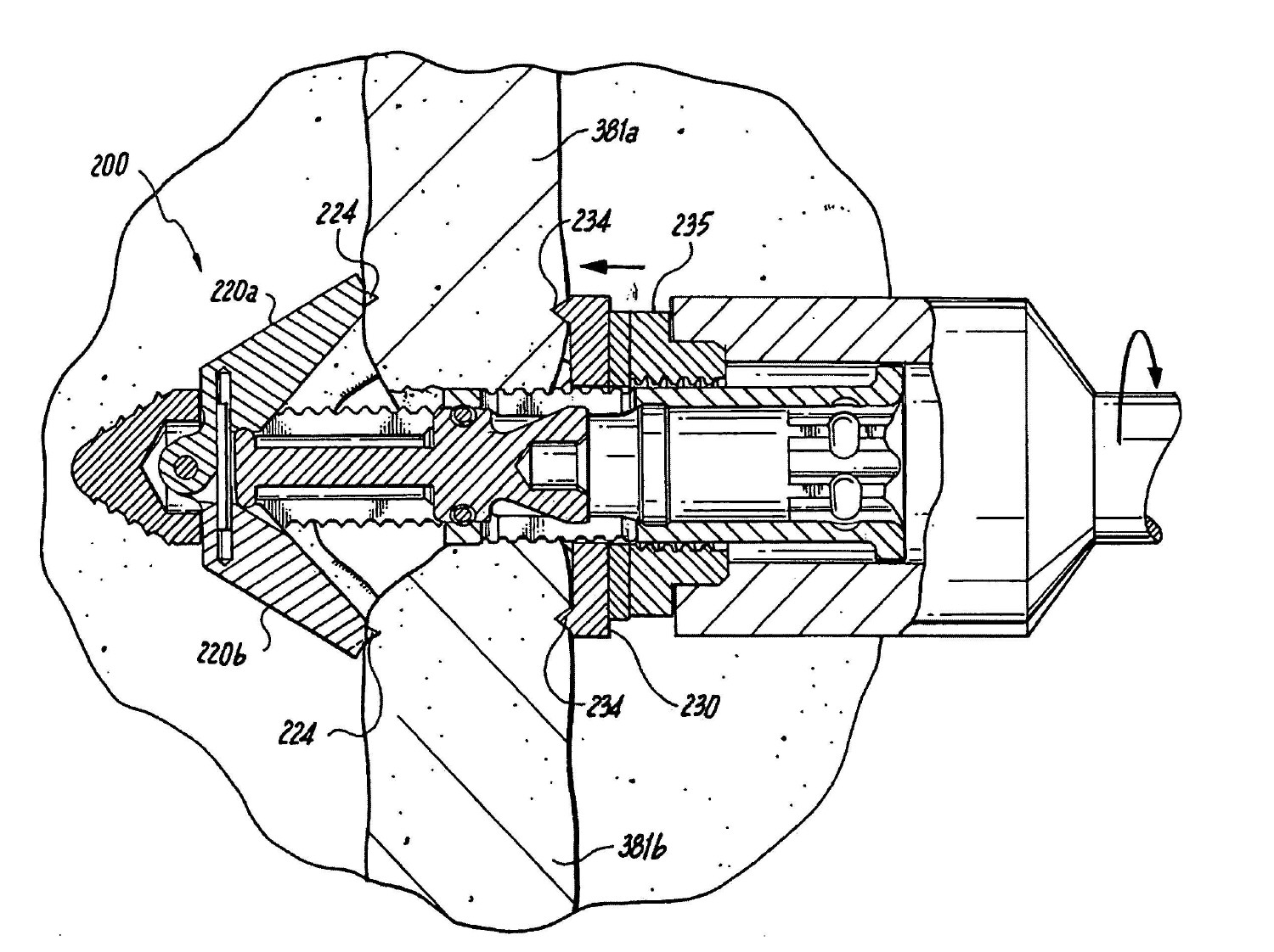
도 14 내지 도 24는 본 발명의 추가 양태에 따르는 극돌기간 임플란트(200)를 도시한다. 임플란트(200)는, 유사한 요소가 상기 사용된 바와 같이 유사한 도면부호로 지정되는, 전술된 실시예의 특정의 특징부를 포함한다. 임플란트(200)는 임플란트(200)에 대한 전체 구조물을 제공하는, 몸체(212)를 포함한다. 도시된 바와 같이, 몸체(212)는 도 20 내지 도 24에 따라 하기에서 더 상세하게 기술되는 바와 같이 목표 극돌기간 공간(382) 내로 임플란트(200)의 삽입을 돕고(도 20 내지 도 24) 뿐만 아니라 목표 극돌기간 공간(382) 내의 환자의 조직과 추가적인 계합을 제공하기 위한 나사산(222)이 제공된다. 추가로, 나사산(222)에 따라, 목표 극돌기간 공간(382)에 인접한 극돌기(381a, 381b)와 임플란트(200)를 확고히 계합시키기 위해 제공된 근위 너트(235)와 몸체(212) 사이에 회전식 계합이 허용된다. 대안으로, 이 임플란트(200) 및 본 발명의 그 외의 다른 임플란트(10, 100)는 이에 나사산이 제공되지 않을 수 있거나 또는 전술된 기능들 중 한 기능을 위해 이의 단지 일부분에만 나사산이 제공될 수 있다. 즉, 요구 시, 나사산(222)은 원위 부분에서가 아니라 나사산(235)과 계합하기 위해, 또는 역으로 계합하기 위해 몸체(112)의 근위 단부 상에서만 제공될 수 있다.Figs. 14-24 illustrate an
전술된 실시예에 따라서, 원위 앵커 부분이 제공되며, 이 실시예에서 2개의 마주보는 전개가능한 블레이드(220)(220a, 220b)와 같이 구성된다. 블레이드(220)는 이를 통과할 뿐만 아니라 몸체(212)를 통과하는 핀(259)에 의해 형성된 공통 피벗(common pivot)이 제공된다. 공통 피벗을 사용함에 따라, 바람직하게는 정확한 형상으로부터의 변형이 가능할지라도 집어넣은 상태에서 몸체(212) 내의 모든 요소를 수용하기 위해 필요한 공간이 최소화된다. 예를 들어, 2개의 개별 피벗은 여전히 본 발명을 보조하는데 있어서 각각의 블레이드(220a, 220b)에 대해 제공될 수 있다. 도시된 바와 같이, 블레이드(220)는 극돌기(381a, 381b)와 같이 상대적으로 인접한 골질 조직과 계합하기 위한 근위 방향으로 향하는 스파이크(224)가 제공된다. 블레이드(220)는 대안으로 스파이크(224)가 없이 제공될 수 있다.According to the described embodiment, a distal anchor portion is provided, which in this embodiment is configured as two opposing deployable blades 220 (220a, 220b). The blade 220 is provided with a common pivot formed by the
블레이드(220a, 220b)는 핀(259)과 계합하기 위한 힌지 부분(223a, 223b)이 각각 제공된다. 도시된 실시예에서, 하나의 힌지 부분(223a)은 U자형 고리(clevis)와 같이 형태가 형성되는 반면 그 외의 다른 힌지 부분(223b)은 U자형 고리 형태의 힌지 부분(223a) 내에 끼워맞춤되도록 형태가 형성된다. The
도시된 실시예에서, 플런저(226)가 제공되며, 플런저는 전술된 바와 같이 각각의 블레이드(220a, 220b) 상에 형성된 내측 캠 표면(240)과 협력하고 캠과 같이 작용하도록 형태 및 구조를 갖는 헤드 부분(228)을 포함한다. 플런저 헤드(228)가 원위 방향으로 이동함에 따라, 블레이드(220a, 200b)의 캠 표면(240)은 플런저 헤드(228)의 외측 표면을 따르며 블레이드(220a, 220b)를 외측을 향하여 반경방향으로 가압한다. 추가로, 전술된 바와 같이 플런저는 근위 내측 리세스(221)를 갖는 근위 헤드(225) 및 근위 방향으로부터 각각 가해진 원위 방향으로의 가압 및 근위 방향으로의 가압을 돕기 위한 비스듬한 원위 표면을 포함할 수 있다. 플런저(226)는 또한, 탄성 캐치(resilient catch, 227)와의 확고한 계합을 위한 리세스(229)를 포함할 수 있다. 캐치(227)는 환형 요홈 또는 리세스(254)와 같이 몸체(212)의 내측 표면 특징부와 플런저(226) 사이를 접촉시키도록 구성된다. 기술된 바와 같이, 탄성 캐치(227)에 따라 플런저(226)가 고정되는 정해진 위치에서 몸체(212)의 전술된 내측 표면 특징부와 함께 플런저(226)의 축방향 움직임이 허용되어 이로부터의 의도되지 않은 움직임이 방지된다. 캐치(227)는 예를 들어, 탄성중합체와 같은 탄성 재료, 또는 토로이달 금속 코일과 같은 탄성 구조물 또는 이들의 조합과 같은 임의의 적합한 재료 또는 형상으로부터 형성될 수 있다. 캐치(227)는 본 발명에 따라서 미국, 캘리포니아주, 푸실 랜치 소재의 발 실 엔지니어링, 인코포레이티드(Bal Seal Engineering, Inc)로부터 입수가능한 발 래치(Bal Latch™)와 같은 캔티드 코일(canted coil)일 수 있다.In the illustrated embodiment, a
전개 시, 블레이드(220)는 임플란트(200)의 길이를 따라 축방향으로 이동할 수 있는 근위 앵커 부분(230)과 협력하도록 작용한다. 너트(235)는 이의 내측 표면 상에 몸체(212)의 외측 표면상에 제공된 나사산(222)과 계합하는 나사산을 포함한다. 따라서, 너트(235)의 회전 움직임은 이의 축방향 움직임을 생성한다. 축방향 움직임이 원위 방향일 때, 너트(235)는 목표 극돌기간 공간(382)을 둘러싸는 골질 구조물(예를 들어, 극돌기(381a, 381b))과 접할 때까지 근위 앵커 부분(230)을 가압한다. 제공 시, 근위 앵커 부분 상의 돌출부 또는 스파이크(234)는 골과의 계합을 돕고, 이에 따라 전체 추골-임플란트 구조물이 안정화된다.In deployment, the blade 220 serves to cooperate with a
도시된 바와 같이, 상측 및 하측 평평한 부분(217a, 217b)을 포함하는 마주보는 평평한 부분(217)은 축방향 움직임은 허용되지만 너트(235)가 움직이는 동안 회전 움직임은 방지되도록 근위 앵커(230)의 대응하는 형태(예를 들어, 평평한)의 부분(237)을 각각 안내한다. 블레이드(220a, 220b)의 식립 및 전개 이후 너트(235)의 의도되지 않은 풀림을 방지하기 위해 로크 와셔(lock washer, 233) 또는 균등한 특징부가 제공될 수 있다.As shown, opposing flattened portions 217, including upper and lower flattened
도 18 내지 도 19의 횡단면도를 참조하면, 도시된 실시예에서, 블레이드(220)는 각각의 블레이드(220a, 220b) 내의 각각의 리세스들 사이에 걸쳐있는 내측 스프링 요소(281)가 제공될 수 있다. 스프링 요소(281)는 통상적으로 블레이드(220a, 220b)를 전개된 상태(개방 상태)로 유지시키기 위해 직선형으로 제공되거나 또는 대안으로 통상적으로 블레이드(220a, 220b)를 집어넣어진 상태(들어간 상태)로 유지시키기 위해 만곡된 형태로 제공될 수 있다. 일 양태에 따라서, 스프링 요소(281)는 만곡되어 제공되며, 식립 이전에 및 식립 중에 집어넣어진 위치를 향하여 내측으로 블레이드(220a, 220b)를 가압한다. 따라서, 플런저(226)에 관하여 스프링(281)은 블레이드(220)의 위치를 유지시키기 위해 제공된다. 도시된 바와 같이, 플런저(226)가 완전히 신장 시, 이의 헤드 부분(228)은 블레이드(220a, 220b)의 프로파일(240) 내에서 대응하는 디텐트(detent, 249)와 계합된다. 헤드 부분(228)에 의한 디텐트(249)의 계합은 블레이드(220a, 220b)의 확고한 전개를 추가로 보장한다.Referring to the cross-sectional views of Figures 18-19, in the illustrated embodiment, the blade 220 may be provided with an
본 발명에 따라서, 스프링 요소(281)는 대안으로 식립 이전, 식립 동안 및 식립 이후 블레이드(220a, 220b)를 전개된 위치를 향하여 외측으로 가압하도록 통상적으로 직선형으로 제공될 수 있다. 그러나, 식립 중에 스프링 요소(281)는 블레이드(220a, 220b)의 내측을 향하는 회전을 허용하여 공정 중에 스프링 요소(281)를 일시적으로 만곡시킨다. 따라서, 식립 중에 스프링(281)은 외측을 향하여 가해진 힘에 대해 블레이드(220a, 220b)의 위치를 유지시키기 위하여 제공된다. 목표 극돌기간 공간(382)에 배치 시, 플런저(226)는 전개된 위치에 블레이드(220a, 220b)를 고정시키기 위하여 원위 방향으로 가압될 수 있다. 플런저(226)의 헤드 부분(228)에 의한 디텐트(249)의 계합에 따라 이 위치의 유지가 추가로 보장된다. 몸체(212)는 이의 근위 단부에 근위 앵커(230)와 너트(235)의 이동을 위한 최근위 한정부를 형성하는 팽창된 직경의 부분(213)을 포함한다. 또한, 보어(250) 내에 형성된 근위 단부 부분에는 삽입 공구와의 계합을 위한 형성된 소켓(251)이 있다. 도시된 바와 같이, 소켓(251)은 규칙적으로 각을 형성하는 간격으로 형성된 평평한 부분을 포함하는 실질적으로 육각형이다. 도시된 정확한 형상으로부터의 실시가능한 변형이 가능하다. 형성된 소켓(251)에 따라 임플란트(200)와 삽입 공구 사이의 상호 회전식 계합이 용이해진다. 또한, 소켓(251)에 대해 횡방향 요홈(253)이 제공되며, 이 횡방향 요홈은 삽입 공구상의 대응하는 요소와 공동으로 이들 간의 의도되지 않은 상호 축방향 이동을 방지시킨다. 삽입 공구상의 대응하는 요소는 예를 들어, 삽입 공구로부터 횡방향(즉, 반경방향)으로 연장된 탄성적으로 및 선택적으로 고정가능한 돌출부일 수 있다. 고정가능한 돌출부는 예를 들어, 고정식 스프링-장착된 구형 요소일 수 있다. In accordance with the present invention, the
전술된 실시예에 따라, 임플란트(200)는 탈회골과 같이 내성장 및/또는 융합을 촉진시키기 위한 골생성-촉진 물질로 보어(250) 내에서 임플란트의 패킹을 허용하기 위하여 하나 이상의 구멍(214)이 제공될 수 있다. In accordance with the foregoing embodiment, the
도 20 내지 도 24는 목표 극돌기간 공간(382) 내로 임플란트(200)의 삽입 및 배치 동안의 다양한 단계를 도시한다. 요약하면, 도 20은, 환자의 피부(388)를 통해 형성된 절개부(389)를 통하여 삽입되는, 만곡된 삽입기 튜브(curved introducer tube, 387)를 통해 등에 장착될 준비 중에 있는 임플란트(200)의 사시도이다. 도 21은 횡방향 삽입 동안에 삽입기 튜브(397)의 루멘 내에서 신장된 삽입 공구(392)에 의해 고정된, 임플란트(200)의 배면도(후면도)이다. 도 22는 몸체(212) 상에 제공된 나사산(222)의 덕택으로 삽입 공구(392)에 의해 가해진 회전력의 적용 하에서 목표 극돌기간 공간(382)으로 횡방향으로 전진하는, 임플란트(200)를 도시하는 배면도이다. 도 23은, 내측 플런저(226)가 원위 방향으로 가압된 상태에서, 원위 앵커 요소-이 경우 블레이드(220a, 220b)를 전개시키는, 임플란트(200)를 도시하는 배면도이다. 그 뒤, 너트(235)가 체결되고, 이에 따라 몸체(212)는 근위 방향으로 가압되며, 또한, 이에 따라 블레이드(220)는 인접한 골질 구조물에 대해 더 확고히 가압되어 도 24에 도시된 바와 같이 극돌기(381a, 381b)가 이들 사이에서 접촉하며, 도 24는 근위 앵커 요소(230)가 인접한 극돌기(381a, 381b)와 계합되는 나사(235)에 의해 원위 방향으로 가압된 상태에 있는 임플란트(200)를 도시하는 배면도이다. Figs. 20-24 illustrate various stages during insertion and placement of
더 구체적으로, 도 20에 도시된 바와 같이, 삽입을 돕기 위해 슬리브(sleeve, 387)가 제공된다. 삽입 방법은 하기에서 더 상세히 기술되는 바와 같이 슬리브(387)를 위한 경로를 형성하고 접근부를 획득하기 위해 스타일릿(stylet), 확장기(dilator) 등의 사용을 포함할 수 있다. 그러나, 본원에 그 전체가 참조로 인용된, 2008년 1월 30일에 출원된 미국특허출원번호 제12/011,905호(미국 공보번호 제2009/0054988호)에 기술된 것과 같이 배면 삽입술(dorsal insertion)이 구현될 수 있다.More specifically, as shown in FIG. 20, a
도시된 바와 같이, 도 20에서, 임플란트(10)로 표시되어 있는 대상 임플란트의 배면 삽입술은 서로 인접한 척추 돌기(vertebral process)(381a, 381b)들 사이에 형성된, 목표 극돌기간 공간(382)에 상응하는 높이에서, 환자의 피부(388)를 통해 절개부(389)를 형성함으로써 시술될 수 있다. As shown, in FIG. 20, the back implantation of the subject implant, indicated by
도 20에 도시된 배면 삽입술에 따라, 임플란트(200), 따라서 또한 슬리브(387)를 가로지르는 경로는 목표 극돌기간 공간(382)과 임플란트(200) 및 상기 경로를 정렬하기 위하여 만곡된다.20, a path that traverses the
대조적으로, 도 21은 목표 극돌기간 공간(382) 내로의 임플란트(200)의 직접적인 횡방향 삽입(direct lateral insertion)을 도시한다. 이 배열에서, 환자의 피부(388) 내에 절개부(399)가 형성되어, 궁극적으로는 슬리브(397)는 조직을 통해 목표 극돌기간 공간(382)으로 전진하며, 이 슬리브를 통해 상기 임플란트(200)가 전진하여, 삽입 장치(392)에 연결된다. 명확함을 위해 슬리브(397)가 없이 예시된 도 22 내지 도 24에 도시된 바와 같이, 임플란트(200)는 삽입 장치(392)에 의해 축방향으로 회전되어서 이에 따라서 임플란트(200)가 목표 극돌기간 공간(382) 내로 맞물리며, 인접한 극돌기(381a, 381b)들이 신연되고, 극돌기(381a, 381b)에 대해 일반적으로 중심에 위치된 최종 위치로 임플란트(200)가 전진된다. 전술된 바와 같이, 개별 도구에 의해 미리 신연이 수행될 수 있으며, 이러한 신연 이후, 이를 유지시키면서 임플란트가 삽입된다. 임플란트(200)가 회전하는 동안, 임플란트(200)와 삽입 장치(392) 사이의 상대적인 축방향 병진운동과 회전은 바람직하게는, 전술된 특징부에 의해 방지된다. 제 위치에 있을 때, 앵커링 블레이드(220a, 220b)는 도 23에 도시된 바와 같이 전개될 수 있다. 그 뒤, 너트(235)가 체결될 수 있으며, 고정 근위 앵커(230)는 극돌기(381a, 381b)와 계합되도록 원위 방향으로 전진한다. In contrast, FIG. 21 shows the direct lateral insertion of the
그 뒤, 요구 시에, 골 내성장 및/또는 척추 융합술(spinal fusion)을 촉진시키기 위해 하나 이상의 골형성 촉진 물질이 임플란트(200) 주위에 및/또는 내에 채워질 수 있다(packed).Thereafter, one or more bone formation enhancing materials may be packed around and / or within the
임플란트(200)를 삽입하기 전에 목표 극돌기간 공간(382) 내에서 개별적인 탭(tap)이 사용될 수 있거나, 또는 전술된 바와 같이 임플란트(200)는 자체-태핑 기능을 제공하는 특징부들이 제공될 수 있다. Individual taps may be used within the target
목표 극돌기간 공간(382) 내로의 척추 임플란트(200)의 횡방향 삽입 방법은, 절개부(399)를 형성하고 난 후, 바람직하게는 형광투시법(fluoroscopy)과 같은 내부 영상 기술(internal imaging technique)을 사용하여, 절개부(399)를 통해 스타일릿(도시되지 않음)을 목표 극돌기간 공간(382)에 횡방향으로 삽입하는 단계를 포함한다. The transverse insertion of the
스타일릿을 삽입함에 따라 삽입 경로가 형성되며, 이 삽입 경로를 따라 하나 이상의 확장기가 순차적으로 전진할 수 있어서 목표 극돌기간 공간(382)과 절개부 사이의 연조직들이 확장될 수 있다. 그 뒤, 슬리브(397)는 상기 삽입 경로를 통해 전진할 수 있다. 슬리브(397)를 삽입한 뒤, 인접한 극돌기(381a, 381b)를 태핑하고 점진적으로 신연시키며 및/또는 삽입되는 임플란트의 적합한 크기의 측정을 돕기 위해 탭(예를 들어, 점진적으로 변화되는 탭)일 수 있는 신연기가 그 뒤 극돌기간 공간(382) 내로 삽입되고 전진될 수 있다.An insertion path is formed by inserting the stylet and one or more expanders can be advanced sequentially along the insertion path so that the soft tissues between the target
요구된 크기의 극돌기간 신연을 위해 적합한 크기를 갖는 임플란트(200)를 선택한 후, 삽입 장치(392)에 의해 고정된 임플란트(200)가 삽입될 수 있으며, 슬리브(397)를 통해 최대 목표 극돌기간 공간(382)까지 전진된 후, 상기 임플란트(200)는 목표 극돌기간 공간(382) 내로 삽입될 수 있다. 나사산 임플란트의 경우, 임플란트(200)를 전진시키고 이미 신연되어 있지 않는 경우 인접한 극돌기(381a, 381b)를 신연시키기 위해 회전 운동이 제공된다. 비-나사산 임플란트의 경우, 임플란트(300)가 원하는 위치에 있을 때까지 횡방향의 압력이 제공될 수 있으며, 그 뒤, 임의의 근위 및/또는 원위 계합 요소가 전개될 수 있다.The
본 명세서에 기술된 임플란트 장치의 다수의 주요 구조적 부품들은 바람직하게는, 예를 들어, 폴리에테르에테르케톤 열가소성 플라스틱(PEEK), 기계가공된 골(machined bone), 티타늄 합금 또는 스테인리스 합금과 같이 골의 탄성계수와 실질적으로 유사한 탄성계수를 갖도록 선택될 수 있는 금속, 세라믹, 중합성 및/또는 복합 재료를 포함한 생물학적 및/또는 생체적합성 재료로부터 형성된다.The major structural components of the implant device described herein are preferably made of a material such as, for example, polyetheretherketone thermoplastic (PEEK), machined bone, titanium alloy or stainless steel alloy, Ceramics, polymeric and / or composite materials that can be selected to have a modulus of elasticity that is substantially similar to the modulus of elasticity of the material.
본 발명의 장치들과 방법들이 선호되는 실시예에 따라 예시되고 기술될지라도, 일 실시예에 따라 기술된 임의의 특징들이 바람직하게는 이러한 특징(들)이 이러한 실시예의 그 외의 다른 특징과 상호 모순되지 않는다면, 심지어 이에 관해 명확히 기술되지 않을지라도 본 발명의 그 외의 다른 실시예에 적용될 수 있다. 그럼에도 불구하고, 본 발명의 사상과 범위로부터 벗어나지 않고 본 발명의 장치 및 방법에 대한 추가 수정 또는 변경이 구현될 수 있음을 용이하게 이해할 것이다.While the apparatuses and methods of the present invention have been illustrated and described in accordance with preferred embodiments, it is to be understood that any feature described in accordance with one embodiment is preferably such that such feature (s) contradicts other features of this embodiment The present invention can be applied to other embodiments of the present invention even if not explicitly described. Nevertheless, it will be readily appreciated that further modifications or changes to the apparatus and method of the present invention may be implemented without departing from the spirit and scope of the invention.
Claims (21)
a) 2개의 인접한 극돌기들(381a,381b) 사이에서 목표 극돌기간 공간(382) 내에 배열하기 위해 이격기로 작용하기 위한 치수 및 구조를 가지고 종 방향 축을 가진 신장된 몸체(212)를 포함하고, 상기 몸체(212)의 외부 표면에 나사산(222)이 형성되며,
b) 상기 몸체(212)의 원위 단부와 연결되고 상기 극돌기들과 연결되며 반경 방향으로 전개되는 두 개의 블레이드(220a, 220b)들을 포함하는 원위 앵커를 포함하고, 상기 두 개의 블레이드들은 상기 몸체(212)의 종 방향 축에 정렬되는 집어 넣어진 위치 및 상기 종 방향 축에 대해 각을 이루며 상기 몸체(212)로부터 반경 방향을 따라 외측으로 돌출하는 전개된 위치사이에서 상기 몸체(212)의 종 방향 축에 대해 횡 방향으로 연장되는 공통의 피봇 축 주위에서 회전하도록 장착되며, 각각의 블레이드(220a, 220b)들은 근위 방향을 향하는 스파이크(224)들을 가지고,
c) 상기 원위 앵커와 함께 상기 두 개의 인접한 극돌기들(381a,381b)을 압축하기 위해 상기 몸체(212)의 원위 단부와 이격된 제1 위치 및 상기 몸체(212)의 원위 단부와 인접한 제2 위치 사이에서 상기 몸체(212)를 따라 종 방향으로 운동하도록 장착된 근위 앵커(230)를 포함하며, 상기 근위 앵커(230)는 축 방향으로 미끄럼 운동하는 플레이트 및 상기 몸체의 나사산 외부 표면과 나사 연결되는 나사산 너트(235)를 포함하여 상기 나사산 너트(235)의 회전운동에 의해 상기 근위 앵커(230)는 축 방향으로 운동하고, 상기 플레이트는 상기 나사산 너트 및 상기 원위 앵커사이에서 축 방향으로 배열되며, 상기 플레이트와 상기 몸체의 상대 회전운동을 방지하기 위해 상기 몸체의 외부 표면은 한 개이상의 평평한 부분(217a, 217b)을 포함하고 상기 평평한 영역은 상기 플레이트의 대응하는 평평한 부분(237)과 연결되는 것을 특징으로 하는 척추 임플란트.
As a spinal implant,
a) an elongate body (212) having a longitudinal axis with dimensions and structure for acting as spacers for arranging in a target interdental space (382) between two adjacent transporters (381a, 381b) A thread 222 is formed on the outer surface of the body 212,
b) a distal anchor comprising two blades (220a, 220b) connected to the distal end of the body (212) and connected to the pulleys and deployed in a radial direction, the two blades being connected to the body And a deployed position projecting outwardly along the radial direction from the body 212 at an angle to the longitudinal axis, the longitudinal axis of the body 212, And each blade 220a, 220b has proximal facing spikes 224, and the blades 220a,
c) a first position spaced apart from the distal end of the body (212) to compress the two adjacent wedges (381a, 381b) with the distal anchor, and a second position adjacent the distal end of the body And a proximal anchor 230 mounted to move longitudinally along the body 212 between the proximal anchor 230 and the proximal anchor 230. The proximal anchor 230 includes an axially slidable plate and a threaded outer surface of the body The proximal anchor 230 is axially moved by rotational movement of the threaded nut 235 including a threaded nut 235 and the plate is axially arranged between the threaded nut and the distal anchor, The outer surface of the body may include one or more flattened portions 217a, 217b to prevent relative rotational movement of the plate and the body, Spinal implant, characterized in that connected to the corresponding flat portion 237.
The vertebral implant of claim 1, wherein the plate comprises a plurality of distal-facing spikes (234) circumferentially spaced and engaged with the puller when the distal anchor is adjacent to the proximal anchor.
2. The spinal implant of claim 1, wherein the body is at least partially hollow and comprises a plurality of openings for tissue ingrowth.
The vertebral implant of claim 1, wherein the body has a tapered head portion that stretches two adjacent transporters while being inserted between two adjacent transporters.
2. The spinal implant of claim 1, wherein the distal anchor has an expanded or deployed state.
The spinal implant of claim 1, wherein the distal anchor has a collapsed or implanted condition.
The vertebral implant of claim 1, wherein the body has an inner chamber and the blades are inserted into the inner chamber before a plurality of radially deployed blades are deployed.
The vertebral implant of claim 1, further comprising an inner plunger (226) for deploying the blades by a camming mechanism.
a) 2개의 인접한 극돌기들(381a,381b) 사이에서 목표 극돌기간 공간(382) 내에 배열하기 위해 이격기로서 작용하기 위한 치수 및 구조를 가지고 종 방향 축을 가진 신장된 몸체(212)를 포함하고, 상기 몸체는 2개의 인접한 극돌기 사이에 삽입되는 동안 두 개의 인접한 극돌기들을 신연시키는 테이퍼구조의 헤드 부분을 가지고, 상기 테이퍼구조의 헤드 부분을 포함한 상기 몸체(212)의 외부 표면에 나사산(222)이 형성되며,
b) 상기 몸체(212)의 원위 단부와 연결되는 원위 앵커를 포함하고, 상기 원위 앵커는 상기 극돌기들의 제1 측부와 연결되며 반경 방향으로 전개되는 두 개의 블레이드(220a, 220b)들을 포함하며, 상기 두 개의 블레이드들은 상기 몸체(212)의 종 방향 축에 정렬되는 집어 넣어진 위치 및 상기 종 방향 축에 대해 각을 이루며 상기 몸체(212)로부터 반경 방향을 따라 외측으로 돌출하는 전개된 위치사이에서 상기 몸체(212)의 종 방향 축에 대해 횡 방향으로 연장되는 공통의 피봇 축 주위에서 회전하도록 장착되며, 각각의 블레이드(220a, 220b)들은 근위 방향을 향하는 스파이크(224)들을 가지고,
c) 상기 테이퍼구조의 헤드 부분으로부터 이격된 제1 위치 및 상기 테이퍼구조의 헤드 부분과 근접한 제2 위치사이에서 상기 몸체(212)를 따라 종 방향으로 운동하도록 장착되고 상기 두 개의 인접한 극돌기(381a,381b)의 제2 측부와 연결되는 근위 앵커(230)를 포함하며, 상기 근위 앵커(230)는 축 방향으로 미끄럼 운동하는 플레이트 및 상기 몸체(212)의 나사산 외부 표면과 나사 연결되는 나사산 너트(235)를 포함하여 상기 나사산 너트(235)의 회전운동에 의해 상기 근위 앵커(230)는 축 방향으로 운동하고, 상기 플레이트는 상기 나사산 너트 및 상기 원위 앵커사이에서 축 방향으로 배열되며, 상기 플레이트와 상기 몸체의 상대 회전운동을 방지하기 위해 상기 몸체의 외부 표면은 한 개이상의 평평한 부분(217a, 217b)을 포함하고 상기 평평한 부분은 상기 플레이트의 대응하는 평평한 부분(237)과 연결되는 것을 특징으로 하는 척추 임플란트.As a spinal implant,
a) includes an elongated body (212) having a longitudinal axis with dimensions and structure for acting as spacers for arranging in a target interdental space (382) between two adjacent transporters (381a, 381b) The body has a tapered head portion that stretches two adjacent transverse rollers while being inserted between two adjacent transporters, and a threaded portion 222 is formed on the outer surface of the body 212 including the head portion of the tapered structure And,
b) a distal anchor connected to a distal end of the body (212), the distal anchor having two blades (220a, 220b) connected to a first side of the pulleys and deployed in a radial direction, The two blades are spaced apart from each other between a deployed position that is angled relative to the longitudinal axis and that is aligned with the longitudinal axis of the body 212 and that protrudes outwardly along the radial direction from the body 212 Each blade 220a, 220b being mounted for rotation about a common pivot axis extending transversely with respect to the longitudinal axis of the body 212, each blade having proximal facing spikes 224,
c) mounted to move longitudinally along the body (212) between a first position spaced from the head portion of the tapered structure and a second position adjacent the head portion of the tapered structure, the two adjacent wings (381a, And a proximal anchor 230 connected to the second side of the body 212. The proximal anchor 230 includes an axially slidable plate and a threaded nut 235 Wherein the proximal anchor 230 is axially moved by rotational movement of the threaded nut 235 and the plate is axially disposed between the threaded nut and the distal anchor, To prevent relative rotational movement of the body, the outer surface of the body includes one or more flattened portions 217a, 217b, Is connected to a corresponding flat portion (237).
Applications Claiming Priority (5)
| Application Number | Priority Date | Filing Date | Title |
|---|---|---|---|
| US20999709P | 2009-03-13 | 2009-03-13 | |
| US61/209,997 | 2009-03-13 | ||
| US12/554,922 | 2009-09-07 | ||
| US12/554,922 US8945184B2 (en) | 2009-03-13 | 2009-09-07 | Interspinous process implant and fusion cage spacer |
| PCT/US2009/006742 WO2010104496A1 (en) | 2009-03-13 | 2009-12-30 | Interspinous process implant and fusion cage spacer |
Publications (2)
| Publication Number | Publication Date |
|---|---|
| KR20120001759A KR20120001759A (en) | 2012-01-04 |
| KR101687977B1 true KR101687977B1 (en) | 2017-01-02 |
Family
ID=41683475
Family Applications (1)
| Application Number | Title | Priority Date | Filing Date |
|---|---|---|---|
| KR1020117024039A Active KR101687977B1 (en) | 2009-03-13 | 2009-12-30 | Interspinous process implant and fusion cage spacer |
Country Status (11)
| Country | Link |
|---|---|
| US (3) | US8945184B2 (en) |
| EP (1) | EP2405836B1 (en) |
| JP (1) | JP5548709B2 (en) |
| KR (1) | KR101687977B1 (en) |
| CN (1) | CN102438536B (en) |
| AU (1) | AU2009341811B2 (en) |
| CA (1) | CA2755431C (en) |
| IL (2) | IL215006A (en) |
| MX (1) | MX2011009399A (en) |
| WO (1) | WO2010104496A1 (en) |
| ZA (1) | ZA201106825B (en) |
Cited By (1)
| Publication number | Priority date | Publication date | Assignee | Title |
|---|---|---|---|---|
| US12133664B2 (en) | 2022-12-13 | 2024-11-05 | Spinal Simplicity, Llc | Medical implant |
Families Citing this family (108)
| Publication number | Priority date | Publication date | Assignee | Title |
|---|---|---|---|---|
| US8152837B2 (en) | 2004-10-20 | 2012-04-10 | The Board Of Trustees Of The Leland Stanford Junior University | Systems and methods for posterior dynamic stabilization of the spine |
| US8409282B2 (en) | 2004-10-20 | 2013-04-02 | Vertiflex, Inc. | Systems and methods for posterior dynamic stabilization of the spine |
| US9023084B2 (en) | 2004-10-20 | 2015-05-05 | The Board Of Trustees Of The Leland Stanford Junior University | Systems and methods for stabilizing the motion or adjusting the position of the spine |
| US8292922B2 (en) | 2004-10-20 | 2012-10-23 | Vertiflex, Inc. | Interspinous spacer |
| US8128662B2 (en) | 2004-10-20 | 2012-03-06 | Vertiflex, Inc. | Minimally invasive tooling for delivery of interspinous spacer |
| US9119680B2 (en) | 2004-10-20 | 2015-09-01 | Vertiflex, Inc. | Interspinous spacer |
| US8317864B2 (en) | 2004-10-20 | 2012-11-27 | The Board Of Trustees Of The Leland Stanford Junior University | Systems and methods for posterior dynamic stabilization of the spine |
| US8425559B2 (en) | 2004-10-20 | 2013-04-23 | Vertiflex, Inc. | Systems and methods for posterior dynamic stabilization of the spine |
| US8123807B2 (en) | 2004-10-20 | 2012-02-28 | Vertiflex, Inc. | Systems and methods for posterior dynamic stabilization of the spine |
| US8167944B2 (en) | 2004-10-20 | 2012-05-01 | The Board Of Trustees Of The Leland Stanford Junior University | Systems and methods for posterior dynamic stabilization of the spine |
| US7763074B2 (en) | 2004-10-20 | 2010-07-27 | The Board Of Trustees Of The Leland Stanford Junior University | Systems and methods for posterior dynamic stabilization of the spine |
| US9161783B2 (en) | 2004-10-20 | 2015-10-20 | Vertiflex, Inc. | Interspinous spacer |
| US8273108B2 (en) | 2004-10-20 | 2012-09-25 | Vertiflex, Inc. | Interspinous spacer |
| US8172855B2 (en) | 2004-11-24 | 2012-05-08 | Abdou M S | Devices and methods for inter-vertebral orthopedic device placement |
| WO2009086010A2 (en) | 2004-12-06 | 2009-07-09 | Vertiflex, Inc. | Spacer insertion instrument |
| US8845726B2 (en) | 2006-10-18 | 2014-09-30 | Vertiflex, Inc. | Dilator |
| US9750544B2 (en) * | 2007-11-02 | 2017-09-05 | Zimmer Biomet Spine, Inc. | Interspinous implants with deployable wing |
| EP2244670B1 (en) | 2008-01-15 | 2017-09-13 | Vertiflex, Inc. | Interspinous spacer |
| US8192466B2 (en) * | 2008-08-27 | 2012-06-05 | Alphatec Spine, Inc. | Conical interspinous apparatus and a method of performing interspinous distraction |
| US12279964B2 (en) | 2008-12-18 | 2025-04-22 | 4Web, Llc | Implants having bone growth promoting agents and methods of using such implants to repair bone structures |
| US9757164B2 (en) * | 2013-01-07 | 2017-09-12 | Spinal Simplicity Llc | Interspinous process implant having deployable anchor blades |
| US8945184B2 (en) * | 2009-03-13 | 2015-02-03 | Spinal Simplicity Llc. | Interspinous process implant and fusion cage spacer |
| US9861399B2 (en) | 2009-03-13 | 2018-01-09 | Spinal Simplicity, Llc | Interspinous process implant having a body with a removable end portion |
| US9179944B2 (en) * | 2009-09-11 | 2015-11-10 | Globus Medical, Inc. | Spinous process fusion devices |
| US8795335B1 (en) | 2009-11-06 | 2014-08-05 | Samy Abdou | Spinal fixation devices and methods of use |
| JP2013509959A (en) * | 2009-11-06 | 2013-03-21 | ジンテス ゲゼルシャフト ミット ベシュレンクテル ハフツング | Minimally invasive interspinous spacer implant and method |
| US8764806B2 (en) | 2009-12-07 | 2014-07-01 | Samy Abdou | Devices and methods for minimally invasive spinal stabilization and instrumentation |
| EP2512357B1 (en) | 2009-12-15 | 2016-07-13 | Vertiflex, Inc. | Spinal spacer for cervical and other vertebra, and associated systems |
| JP5272279B2 (en) * | 2010-03-09 | 2013-08-28 | 国立大学法人神戸大学 | Interspinous process implant |
| WO2012037285A2 (en) * | 2010-09-14 | 2012-03-22 | Joule Unlimited Technologies, Inc. | Methods and compositions for targeting heterologous integral membrane proteins to the cyanobacterial plasma membrane |
| WO2012040477A2 (en) * | 2010-09-23 | 2012-03-29 | Alphatec Spine, Inc. | Clamping interspinous spacer apparatus and methods of use |
| US8876866B2 (en) * | 2010-12-13 | 2014-11-04 | Globus Medical, Inc. | Spinous process fusion devices and methods thereof |
| US8906092B2 (en) * | 2011-01-24 | 2014-12-09 | Samy Abdou | Spinous process fixation devices and methods of use |
| US20120215262A1 (en) * | 2011-02-16 | 2012-08-23 | Interventional Spine, Inc. | Spinous process spacer and implantation procedure |
| US9149306B2 (en) | 2011-06-21 | 2015-10-06 | Seaspine, Inc. | Spinous process device |
| US8845728B1 (en) | 2011-09-23 | 2014-09-30 | Samy Abdou | Spinal fixation devices and methods of use |
| EP2763614B1 (en) * | 2011-10-03 | 2017-04-26 | In Queue Innovations, LLC | Interspinous process fusion device |
| CA2856259A1 (en) * | 2011-11-17 | 2013-05-23 | Howmedica Osteonics Corp. | Interspinous spacers and associated methods of use and manufacture |
| US20130226240A1 (en) | 2012-02-22 | 2013-08-29 | Samy Abdou | Spinous process fixation devices and methods of use |
| US9693876B1 (en) | 2012-03-30 | 2017-07-04 | Ali H. MESIWALA | Spinal fusion implant and related methods |
| US9198767B2 (en) | 2012-08-28 | 2015-12-01 | Samy Abdou | Devices and methods for spinal stabilization and instrumentation |
| US12115071B2 (en) | 2012-09-25 | 2024-10-15 | 4Web, Llc | Programmable intramedullary implants and methods of using programmable intramedullary implants to repair bone structures |
| US9320617B2 (en) | 2012-10-22 | 2016-04-26 | Cogent Spine, LLC | Devices and methods for spinal stabilization and instrumentation |
| US12193948B2 (en) | 2013-03-13 | 2025-01-14 | Life Spine, Inc. | Expandable implant assembly |
| US10426632B2 (en) | 2013-03-13 | 2019-10-01 | Life Spine, Inc. | Expandable spinal interbody assembly |
| US9675303B2 (en) | 2013-03-15 | 2017-06-13 | Vertiflex, Inc. | Visualization systems, instruments and methods of using the same in spinal decompression procedures |
| EP2967873B1 (en) * | 2013-03-15 | 2024-09-25 | 4-web, Inc. | Traumatic bone fracture repair systems |
| CN104116579B (en) * | 2013-04-28 | 2016-08-03 | 苏州海欧斯医疗器械有限公司 | Implantation unit is strutted between a kind of Via Posterior Spinal Approach ridge |
| JP6500013B2 (en) | 2013-05-29 | 2019-04-10 | スパイナル シンプリシティ エルエルシーSpinal Simplicity LLC | Instrument for inserting an interspinous implant |
| US11801075B2 (en) * | 2013-05-29 | 2023-10-31 | Spinal Simplicity, Llc | Instrument for inserting an interspinous process implant |
| CN103431902B (en) * | 2013-08-30 | 2015-05-06 | 常州鼎健医疗器械有限公司 | Vertebral body fusion device |
| US10631901B2 (en) | 2014-03-26 | 2020-04-28 | Medacta International Sa | Device for implanting a surgical screw |
| EP3139848A4 (en) | 2014-05-07 | 2018-06-13 | Vertiflex, Inc. | Spinal nerve decompression systems, dilation systems, and methods of using the same |
| USD764054S1 (en) | 2014-05-29 | 2016-08-16 | Spinal Simplicity Llc. | Insertion instrument |
| JP6781170B2 (en) * | 2015-05-22 | 2020-11-04 | スパイナル シンプリシティ エルエルシーSpinal Simplicity LLC | Interspinous process graft with body with removable ends |
| US10857003B1 (en) | 2015-10-14 | 2020-12-08 | Samy Abdou | Devices and methods for vertebral stabilization |
| US9937054B2 (en) * | 2016-01-28 | 2018-04-10 | Warsaw Orthopedic, Inc. | Expandable implant and insertion tool |
| CN105605058A (en) * | 2016-03-25 | 2016-05-25 | 张子豹 | V-shaped universal expansion bolt |
| CN105662565B (en) * | 2016-03-29 | 2018-03-02 | 苏州点合医疗科技有限公司 | Support meanss between the two-way expansion type vertebra of a kind of X-axis, Y-axis |
| US20220226027A1 (en) * | 2016-04-14 | 2022-07-21 | Spinal Simplicity, Llc | Interspinous implant insertion instrument with wing actuation tool |
| US10420591B2 (en) | 2016-04-14 | 2019-09-24 | Spinal Simplicity, Llc | Interspinous implant insertion instrument with staggered path implant deployment mechanism |
| US11510710B2 (en) * | 2016-04-14 | 2022-11-29 | Spinal Simplicity, Llc | Locking system for interspinous implant insertion instrument |
| ES2870603T3 (en) | 2016-09-07 | 2021-10-27 | Vertos Medical Inc | Percutaneous lateral recess resection instruments |
| US10973648B1 (en) | 2016-10-25 | 2021-04-13 | Samy Abdou | Devices and methods for vertebral bone realignment |
| US10744000B1 (en) | 2016-10-25 | 2020-08-18 | Samy Abdou | Devices and methods for vertebral bone realignment |
| CN108236525A (en) * | 2016-12-27 | 2018-07-03 | 重庆润泽医药有限公司 | A kind of bone surgery tantalum bar system |
| CN108236530A (en) * | 2016-12-27 | 2018-07-03 | 重庆润泽医药有限公司 | Bone surgery tantalum bar system |
| US10041518B1 (en) * | 2017-01-09 | 2018-08-07 | Heartland Precision Fasteners, Inc. | Captive screw |
| EP3570719B1 (en) | 2017-01-18 | 2021-04-21 | Boston Scientific Scimed, Inc. | Medical systems, devices, and related methods |
| US20200113558A1 (en) * | 2017-03-16 | 2020-04-16 | Cannuflow, Inc. | System And Method For Fixing Sheet-Like Materials To A Target Tissue |
| US11896494B2 (en) | 2017-07-10 | 2024-02-13 | Life Spine, Inc. | Expandable implant assembly |
| US11135069B2 (en) * | 2018-03-06 | 2021-10-05 | Eit Emerging Implant Technologies Gmbh | Intervertebral cages with deployable anchors |
| IT201800003973A1 (en) * | 2018-03-23 | 2019-09-23 | Techlamed S R L | DEVICE FOR INTERSPINUS FUSION |
| US11179248B2 (en) | 2018-10-02 | 2021-11-23 | Samy Abdou | Devices and methods for spinal implantation |
| US11123122B2 (en) | 2019-02-27 | 2021-09-21 | Warsaw Orthopedic, Inc. | Anatomy buttressing adaptor |
| CN112343914A (en) * | 2019-03-04 | 2021-02-09 | 李吴军 | Self-locking screw suitable for blind hole implantation |
| US11382764B2 (en) | 2019-06-10 | 2022-07-12 | Life Spine, Inc. | Expandable implant assembly with compression features |
| US12042395B2 (en) | 2019-06-11 | 2024-07-23 | Life Spine, Inc. | Expandable implant assembly |
| AU2020385014B2 (en) | 2019-11-15 | 2025-07-31 | 4Web, Inc. | Piezoelectric coated implants and methods of using piezoelectric coated implants to repair bone structures |
| CN110848223A (en) * | 2019-11-22 | 2020-02-28 | 国唐汽车有限公司 | Locking device |
| EP4132392B1 (en) * | 2020-04-08 | 2024-08-28 | Diametros Medical S.r.l. | Interspinous vertebral distractor |
| WO2021205211A1 (en) * | 2020-04-08 | 2021-10-14 | Diametros Medical S.R.L. | Interspinous vertebral distraction method |
| US12396762B2 (en) | 2020-04-08 | 2025-08-26 | Diametros Medical S.R.L. | Interspinous vertebral distractor |
| US11857432B2 (en) | 2020-04-13 | 2024-01-02 | Life Spine, Inc. | Expandable implant assembly |
| US11602439B2 (en) | 2020-04-16 | 2023-03-14 | Life Spine, Inc. | Expandable implant assembly |
| US12336917B2 (en) | 2020-05-15 | 2025-06-24 | Life Spine, Inc. | Steerable implant assembly |
| US11723778B1 (en) | 2021-09-23 | 2023-08-15 | Nofusco Corporation | Vertebral implant system and methods of use |
| US11883300B2 (en) | 2020-06-15 | 2024-01-30 | Nofusco Corporation | Orthopedic implant system and methods of use |
| EP4164524A4 (en) | 2020-06-15 | 2024-07-17 | Foundation Surgical Group, Inc. | INTRAVERTEBRAL IMPLANT SYSTEM AND METHOD OF USE |
| US12144742B2 (en) | 2020-06-15 | 2024-11-19 | Foundation Surgical Group, Inc. | Implant system and methods of use |
| US11602440B2 (en) | 2020-06-25 | 2023-03-14 | Life Spine, Inc. | Expandable implant assembly |
| US12201531B2 (en) | 2020-07-08 | 2025-01-21 | 4Web, Llc | Implants having bone growth promoting agents contained within biodegradable materials |
| US11311388B2 (en) * | 2020-08-20 | 2022-04-26 | Spinal Simplicity, Llc | Interspinous process implant |
| US11534310B2 (en) | 2020-08-20 | 2022-12-27 | Spinal Simplicity, Llc | Interspinous process implant |
| US11554020B2 (en) | 2020-09-08 | 2023-01-17 | Life Spine, Inc. | Expandable implant with pivoting control assembly |
| US11571221B2 (en) | 2020-10-22 | 2023-02-07 | Spinal Simplicity, Llc | Combined bone tap and rasp |
| EP4426216B1 (en) | 2022-02-15 | 2025-06-04 | Boston Scientific Neuromodulation Corporation | Interspinous spacer and systems utilizing the interspinous spacer |
| WO2023196535A1 (en) | 2022-04-08 | 2023-10-12 | Spinal Simplicity, Llc | Interspinous implant insertion instrument with wing actuation tool |
| US11766280B1 (en) * | 2022-04-08 | 2023-09-26 | Spinal Simplicity, Llc | Interspinous implant insertion instrument with wing actuation tool |
| US11672572B1 (en) | 2022-04-08 | 2023-06-13 | Spinal Simplicity, Llc | Disposable interspinous implant insertion instrument |
| WO2023245144A1 (en) | 2022-06-16 | 2023-12-21 | Vertos Medical, Inc. | Integrated instrument assembly |
| US11849975B1 (en) | 2022-11-09 | 2023-12-26 | Spinal Simplicity, Llc | Methods for single incision anterior and posterior spinal fusion procedure |
| US12186199B2 (en) | 2022-11-15 | 2025-01-07 | Spinal Simplicity, Llc | Shield for spinal defect |
| US11992410B1 (en) | 2022-12-13 | 2024-05-28 | Spinal Simplicity, Llc | Sacroiliac joint fusion implants, insertion instruments, and methods |
| US12433646B2 (en) | 2023-02-21 | 2025-10-07 | Boston Scientific Neuromodulation Corporation | Interspinous spacer with actuator locking arrangements and methods and systems |
| US12390340B2 (en) | 2023-03-15 | 2025-08-19 | Boston Scientific Neuromodulation Corporation | Interspinous spacer with a range of deployment positions and methods and systems |
| CN116549082A (en) * | 2023-05-04 | 2023-08-08 | 北京市春立正达医疗器械股份有限公司 | Vertebral body anchor distraction device |
| CN117442317A (en) * | 2023-11-28 | 2024-01-26 | 北京市春立正达医疗器械股份有限公司 | Interspinous process stabilizing device |
Citations (3)
| Publication number | Priority date | Publication date | Assignee | Title |
|---|---|---|---|---|
| US20070032790A1 (en) * | 2005-08-05 | 2007-02-08 | Felix Aschmann | Apparatus for treating spinal stenosis |
| WO2008088613A2 (en) * | 2007-01-11 | 2008-07-24 | Lanx, Inc. | Spinous process implants and associated methods |
| JP2008532730A (en) * | 2005-03-21 | 2008-08-21 | セント フランシス メディカル テクノロジーズ インコーポレイテッド | Interspinous process implants with deployable wings and implantation methods |
Family Cites Families (213)
| Publication number | Priority date | Publication date | Assignee | Title |
|---|---|---|---|---|
| US624969A (en) * | 1899-05-16 | Peter peterson | ||
| US1195013A (en) * | 1916-08-15 | Leak-stopper | ||
| US1112622A (en) * | 1912-03-04 | 1914-10-06 | George D Jones | Outlet-valve for irrigating devices. |
| US1153797A (en) * | 1915-04-29 | 1915-09-14 | Jules Emile Kegreisz | Expansion-anchor. |
| US1346578A (en) * | 1920-02-28 | 1920-07-13 | Walter E Windsor | Bolt-fastening |
| US2077804A (en) * | 1936-05-19 | 1937-04-20 | Morrison Gordon Monroe | Device for treating fractures of the neck of the femur |
| US2771259A (en) * | 1952-04-10 | 1956-11-20 | Faries Mfg Co | Wall mirror mounting |
| US3921334A (en) * | 1974-02-06 | 1975-11-25 | Sr William R Black | Window guard apparatus |
| US4116104A (en) | 1977-04-15 | 1978-09-26 | Arvest Gethner Kennedy | Toggle bolt wing nut retainer |
| EP0002654B1 (en) * | 1977-12-24 | 1982-01-20 | Heinrich Liebig | Fastening device with a dowel positively locking in a undercut bore |
| US4530630A (en) * | 1982-07-14 | 1985-07-23 | Brown Russell L | Expanding anchor fastener |
| US4519100A (en) * | 1982-09-30 | 1985-05-28 | Orthopedic Equipment Co. Inc. | Distal locking intramedullary nail |
| US4822226A (en) * | 1983-08-08 | 1989-04-18 | Kennedy Arvest G | Wing nut retainer and extractor |
| US4573844A (en) * | 1983-11-25 | 1986-03-04 | Smith Gareth J | Anchoring bolt device |
| US4721103A (en) * | 1985-01-31 | 1988-01-26 | Yosef Freedland | Orthopedic device |
| US4632101A (en) * | 1985-01-31 | 1986-12-30 | Yosef Freedland | Orthopedic fastener |
| US4599086A (en) * | 1985-06-07 | 1986-07-08 | Doty James R | Spine stabilization device and method |
| GB8718708D0 (en) * | 1987-08-07 | 1987-09-16 | Mehdian S M H | Apparatus for treatment of spinal disorders |
| US5098433A (en) * | 1989-04-12 | 1992-03-24 | Yosef Freedland | Winged compression bolt orthopedic fastener |
| US5209621A (en) * | 1991-08-27 | 1993-05-11 | Burbidge Myron L | Toggle bolt stabilizer |
| IT1257908B (en) * | 1992-07-10 | 1996-02-16 | Mini Ricerca Scient Tecnolog | PROCEDURE FOR THE PRODUCTION OF ITTRIO-90 AND ITTRIO-90 GENERATOR |
| US5514180A (en) * | 1994-01-14 | 1996-05-07 | Heggeness; Michael H. | Prosthetic intervertebral devices |
| US6093207A (en) * | 1994-03-18 | 2000-07-25 | Pisharodi; Madhavan | Middle expanded, removable intervertebral disk stabilizer disk |
| FR2722980B1 (en) * | 1994-07-26 | 1996-09-27 | Samani Jacques | INTERTEPINOUS VERTEBRAL IMPLANT |
| US5782919A (en) * | 1995-03-27 | 1998-07-21 | Sdgi Holdings, Inc. | Interbody fusion device and method for restoration of normal spinal anatomy |
| US6077265A (en) * | 1995-04-21 | 2000-06-20 | Werding; Gerd | Nail for fixing the position and shape of broken long bones |
| DE19603887C2 (en) * | 1996-02-03 | 1998-07-02 | Lerch Karl Dieter | Arrangement for fixing a piece of bone that has been removed from the skull capsule for the purpose of the surgical intervention to the remaining skull leg |
| US5700264A (en) * | 1996-07-01 | 1997-12-23 | Zucherman; James F. | Apparatus and method for preparing a site for an interbody fusion implant |
| US5849004A (en) * | 1996-07-17 | 1998-12-15 | Bramlet; Dale G. | Surgical anchor |
| US5968098A (en) | 1996-10-22 | 1999-10-19 | Surgical Dynamics, Inc. | Apparatus for fusing adjacent bone structures |
| US6632224B2 (en) * | 1996-11-12 | 2003-10-14 | Triage Medical, Inc. | Bone fixation system |
| US6648890B2 (en) * | 1996-11-12 | 2003-11-18 | Triage Medical, Inc. | Bone fixation system with radially extendable anchor |
| US5893850A (en) * | 1996-11-12 | 1999-04-13 | Cachia; Victor V. | Bone fixation device |
| US6027504A (en) * | 1996-12-06 | 2000-02-22 | Mcguire; David A. | Device and method for producing osteotomies |
| US7201751B2 (en) * | 1997-01-02 | 2007-04-10 | St. Francis Medical Technologies, Inc. | Supplemental spine fixation device |
| US7306628B2 (en) | 2002-10-29 | 2007-12-11 | St. Francis Medical Technologies | Interspinous process apparatus and method with a selectably expandable spacer |
| US6902566B2 (en) * | 1997-01-02 | 2005-06-07 | St. Francis Medical Technologies, Inc. | Spinal implants, insertion instruments, and methods of use |
| US20050245937A1 (en) * | 2004-04-28 | 2005-11-03 | St. Francis Medical Technologies, Inc. | System and method for insertion of an interspinous process implant that is rotatable in order to retain the implant relative to the spinous processes |
| US5860977A (en) * | 1997-01-02 | 1999-01-19 | Saint Francis Medical Technologies, Llc | Spine distraction implant and method |
| US6156038A (en) | 1997-01-02 | 2000-12-05 | St. Francis Medical Technologies, Inc. | Spine distraction implant and method |
| US5836948A (en) | 1997-01-02 | 1998-11-17 | Saint Francis Medical Technologies, Llc | Spine distraction implant and method |
| US6712819B2 (en) * | 1998-10-20 | 2004-03-30 | St. Francis Medical Technologies, Inc. | Mating insertion instruments for spinal implants and methods of use |
| US7101375B2 (en) | 1997-01-02 | 2006-09-05 | St. Francis Medical Technologies, Inc. | Spine distraction implant |
| US6695842B2 (en) * | 1997-10-27 | 2004-02-24 | St. Francis Medical Technologies, Inc. | Interspinous process distraction system and method with positionable wing and method |
| US6514256B2 (en) * | 1997-01-02 | 2003-02-04 | St. Francis Medical Technologies, Inc. | Spine distraction implant and method |
| US6068630A (en) * | 1997-01-02 | 2000-05-30 | St. Francis Medical Technologies, Inc. | Spine distraction implant |
| US6451019B1 (en) * | 1998-10-20 | 2002-09-17 | St. Francis Medical Technologies, Inc. | Supplemental spine fixation device and method |
| US7959652B2 (en) | 2005-04-18 | 2011-06-14 | Kyphon Sarl | Interspinous process implant having deployable wings and method of implantation |
| US6796983B1 (en) * | 1997-01-02 | 2004-09-28 | St. Francis Medical Technologies, Inc. | Spine distraction implant and method |
| US5704746A (en) * | 1997-01-30 | 1998-01-06 | Illinois Tool Works Inc. | Plastic fastener for threaded blind aperture |
| US5876457A (en) * | 1997-05-20 | 1999-03-02 | George J. Picha | Spinal implant |
| US5919194A (en) * | 1997-07-21 | 1999-07-06 | Anderson; David L. | Orthopaedic implant |
| US6264677B1 (en) * | 1997-10-15 | 2001-07-24 | Applied Biological Concepts, Inc. | Wedge screw suture anchor |
| JP4158339B2 (en) * | 1997-10-27 | 2008-10-01 | メドトロニック スパイン エルエルシー | Spinal distraction implant |
| FR2775183B1 (en) * | 1998-02-20 | 2000-08-04 | Jean Taylor | INTER-SPINOUS PROSTHESIS |
| US6045552A (en) * | 1998-03-18 | 2000-04-04 | St. Francis Medical Technologies, Inc. | Spine fixation plate system |
| US6099527A (en) * | 1998-04-30 | 2000-08-08 | Spinal Concepts, Inc. | Bone protector and method |
| DE19822802C2 (en) * | 1998-05-20 | 2001-11-08 | Medicon Eg Chirurgiemechaniker | Device for distraction of bone segments, especially in the jaw area |
| US6017342A (en) * | 1998-08-05 | 2000-01-25 | Beere Precision Medical Instrumnets, Inc. | Compression and distraction instrument |
| US6235058B1 (en) * | 1998-10-19 | 2001-05-22 | Douglas B. Huene | Bone plug anchoring device and methods for anchoring one or more tendons or other grafts using the bone plug anchoring device |
| US7029473B2 (en) * | 1998-10-20 | 2006-04-18 | St. Francis Medical Technologies, Inc. | Deflectable spacer for use as an interspinous process implant and method |
| US6652527B2 (en) | 1998-10-20 | 2003-11-25 | St. Francis Medical Technologies, Inc. | Supplemental spine fixation device and method |
| US7189234B2 (en) * | 1998-10-20 | 2007-03-13 | St. Francis Medical Technologies, Inc. | Interspinous process implant sizer and distractor with a split head and size indicator and method |
| US6652534B2 (en) | 1998-10-20 | 2003-11-25 | St. Francis Medical Technologies, Inc. | Apparatus and method for determining implant size |
| US6183517B1 (en) * | 1998-12-16 | 2001-02-06 | Loubert Suddaby | Expandable intervertebral fusion implant and applicator |
| WO2000045753A1 (en) * | 1999-02-04 | 2000-08-10 | Sdgi Holdings, Inc. | Improved interbody fusion device with anti-rotation features |
| AU2999900A (en) * | 1999-02-18 | 2000-09-04 | Ken Y. Hsu | Hair used as a biologic disk, replacement, and/or structure and method |
| US6245108B1 (en) * | 1999-02-25 | 2001-06-12 | Spineco | Spinal fusion implant |
| AU4988700A (en) * | 1999-05-05 | 2000-11-17 | Gary K. Michelson | Spinal fusion implants with opposed locking screws |
| US6770096B2 (en) * | 1999-07-01 | 2004-08-03 | Spinevision S.A. | Interbody spinal stabilization cage and spinal stabilization method |
| US6783546B2 (en) * | 1999-09-13 | 2004-08-31 | Keraplast Technologies, Ltd. | Implantable prosthetic or tissue expanding device |
| US6203260B1 (en) * | 1999-09-15 | 2001-03-20 | Charles Henline | Toggle bolt assembly with bolt centering spacer |
| US6379363B1 (en) * | 1999-09-24 | 2002-04-30 | Walter Lorenz Surgical, Inc. | Method and apparatus for reattachment of a cranial flap using a cranial clamp |
| FR2799640B1 (en) * | 1999-10-15 | 2002-01-25 | Spine Next Sa | IMPLANT INTERVETEBRAL |
| ATE285207T1 (en) | 1999-10-22 | 2005-01-15 | Archus Orthopedics Inc | FACET ARTHROPLASTY DEVICES |
| US6435789B2 (en) * | 1999-12-21 | 2002-08-20 | Powers Fasteners | Self drilling swivel toggle anchor |
| JP4509308B2 (en) * | 2000-01-28 | 2010-07-21 | 若井産業株式会社 | Rotating nut |
| US6402750B1 (en) * | 2000-04-04 | 2002-06-11 | Spinlabs, Llc | Devices and methods for the treatment of spinal disorders |
| US7963966B2 (en) * | 2000-06-06 | 2011-06-21 | Cole J Dean | Bone fixation system and method of use |
| FR2811540B1 (en) * | 2000-07-12 | 2003-04-25 | Spine Next Sa | IMPORTING INTERVERTEBRAL IMPLANT |
| BR0112701B1 (en) * | 2000-07-27 | 2011-10-18 | cranial flap retainer. | |
| JP3734146B2 (en) * | 2000-08-07 | 2006-01-11 | 光洋器材株式会社 | Board anchor |
| AU1312402A (en) * | 2000-10-11 | 2002-04-22 | Michael D Mason | Graftless spinal fusion device |
| FR2818530B1 (en) | 2000-12-22 | 2003-10-31 | Spine Next Sa | INTERVERTEBRAL IMPLANT WITH DEFORMABLE SHIM |
| US6779316B2 (en) * | 2001-01-31 | 2004-08-24 | Kenneth Carroll | Safety anchor |
| US6673113B2 (en) * | 2001-10-18 | 2004-01-06 | Spinecore, Inc. | Intervertebral spacer device having arch shaped spring elements |
| US6849093B2 (en) * | 2001-03-09 | 2005-02-01 | Gary K. Michelson | Expansion constraining member adapted for use with an expandable interbody spinal fusion implant and method for use thereof |
| US7686807B2 (en) * | 2001-03-22 | 2010-03-30 | Interventional Spine, Inc. | Tool for bone fixation device |
| US7128760B2 (en) * | 2001-03-27 | 2006-10-31 | Warsaw Orthopedic, Inc. | Radially expanding interbody spinal fusion implants, instrumentation, and methods of insertion |
| TWI229138B (en) * | 2001-06-12 | 2005-03-11 | Unaxis Balzers Ag | Magnetron-sputtering source |
| US6926728B2 (en) * | 2001-07-18 | 2005-08-09 | St. Francis Medical Technologies, Inc. | Curved dilator and method |
| FR2828398B1 (en) | 2001-08-08 | 2003-09-19 | Jean Taylor | VERTEBRA STABILIZATION ASSEMBLY |
| US20040024463A1 (en) * | 2001-08-27 | 2004-02-05 | Thomas James C. | Expandable implant for partial disc replacement and reinforcement of a disc partially removed in a discectomy and for reduction and maintenance of alignment of cancellous bone fractures and methods and apparatuses for same |
| US6669699B2 (en) * | 2001-11-30 | 2003-12-30 | Spinecore, Inc. | Distraction instrument for use in anterior cervical fixation surgery |
| US6689135B2 (en) * | 2002-01-25 | 2004-02-10 | Albert Enayati | Expandable bone fastener and installation tool |
| US6733534B2 (en) * | 2002-01-29 | 2004-05-11 | Sdgi Holdings, Inc. | System and method for spine spacing |
| AR038680A1 (en) * | 2002-02-19 | 2005-01-26 | Synthes Ag | INTERVERTEBRAL IMPLANT |
| EP1346708A1 (en) * | 2002-03-20 | 2003-09-24 | A-Spine Holding Group Corp. | Three-hooked device for fixing spinal column |
| US6932834B2 (en) * | 2002-06-27 | 2005-08-23 | Ethicon, Inc. | Suture anchor |
| US6682564B1 (en) * | 2002-07-02 | 2004-01-27 | Luis Duarte | Intervertebral support device and related methods |
| DE60330010D1 (en) | 2002-07-19 | 2009-12-24 | Interventional Spine Inc | DEVICE FOR SPINAL FUSING |
| US7089234B2 (en) * | 2002-07-31 | 2006-08-08 | International Business Machines Corporation | Communicating state information in a network employing extended queries and extended responses |
| US6709212B1 (en) * | 2002-09-05 | 2004-03-23 | Hewlett-Packard Development Company, L.P. | Toggling fastening device |
| US6719509B1 (en) * | 2002-10-04 | 2004-04-13 | Joker Ind Co Ltd | Expansion screw |
| FR2845741B1 (en) * | 2002-10-11 | 2005-01-21 | Itw De France | RIVET WITH ELASTIC LEGS |
| US7125425B2 (en) | 2002-10-21 | 2006-10-24 | Sdgi Holdings, Inc. | Systems and techniques for restoring and maintaining intervertebral anatomy |
| US7497859B2 (en) * | 2002-10-29 | 2009-03-03 | Kyphon Sarl | Tools for implanting an artificial vertebral disk |
| US8048117B2 (en) * | 2003-05-22 | 2011-11-01 | Kyphon Sarl | Interspinous process implant and method of implantation |
| US7083649B2 (en) * | 2002-10-29 | 2006-08-01 | St. Francis Medical Technologies, Inc. | Artificial vertebral disk replacement implant with translating pivot point |
| US7749252B2 (en) * | 2005-03-21 | 2010-07-06 | Kyphon Sarl | Interspinous process implant having deployable wing and method of implantation |
| US8221463B2 (en) * | 2002-10-29 | 2012-07-17 | Kyphon Sarl | Interspinous process implants and methods of use |
| US8070778B2 (en) | 2003-05-22 | 2011-12-06 | Kyphon Sarl | Interspinous process implant with slide-in distraction piece and method of implantation |
| US7909853B2 (en) * | 2004-09-23 | 2011-03-22 | Kyphon Sarl | Interspinous process implant including a binder and method of implantation |
| US20060271194A1 (en) | 2005-03-22 | 2006-11-30 | St. Francis Medical Technologies, Inc. | Interspinous process implant having deployable wing as an adjunct to spinal fusion and method of implantation |
| US20060264939A1 (en) | 2003-05-22 | 2006-11-23 | St. Francis Medical Technologies, Inc. | Interspinous process implant with slide-in distraction piece and method of implantation |
| US8147548B2 (en) * | 2005-03-21 | 2012-04-03 | Kyphon Sarl | Interspinous process implant having a thread-shaped wing and method of implantation |
| US20060064165A1 (en) * | 2004-09-23 | 2006-03-23 | St. Francis Medical Technologies, Inc. | Interspinous process implant including a binder and method of implantation |
| US7118572B2 (en) * | 2003-02-03 | 2006-10-10 | Orthopedic Designs, Inc. | Femoral neck compression screw system with ortho-biologic material delivery capability |
| US20050049590A1 (en) * | 2003-03-07 | 2005-03-03 | Neville Alleyne | Spinal implant with securement spikes |
| JP3532559B1 (en) * | 2003-04-04 | 2004-05-31 | 光洋器材株式会社 | Blind bolts and blind nuts |
| US20040208722A1 (en) * | 2003-04-17 | 2004-10-21 | Pop-In Pop-Out, Inc. | Fastener adapted for use with a structural member |
| US6951561B2 (en) * | 2003-05-06 | 2005-10-04 | Triage Medical, Inc. | Spinal stabilization device |
| ATE442110T1 (en) | 2003-07-23 | 2009-09-15 | Ebi Llc | EXPANDABLE INTERVERBEL IMPLANT |
| US6884012B2 (en) * | 2003-09-04 | 2005-04-26 | Illinois Tool Works Inc. | Heavy duty toggle bolt fastener assembly, and method of installing and removing the same |
| US7320707B2 (en) * | 2003-11-05 | 2008-01-22 | St. Francis Medical Technologies, Inc. | Method of laterally inserting an artificial vertebral disk replacement implant with crossbar spacer |
| US7503935B2 (en) * | 2003-12-02 | 2009-03-17 | Kyphon Sarl | Method of laterally inserting an artificial vertebral disk replacement with translating pivot point |
| US20050209603A1 (en) * | 2003-12-02 | 2005-09-22 | St. Francis Medical Technologies, Inc. | Method for remediation of intervertebral disks |
| US7217291B2 (en) * | 2003-12-08 | 2007-05-15 | St. Francis Medical Technologies, Inc. | System and method for replacing degenerated spinal disks |
| US20050129482A1 (en) * | 2003-12-16 | 2005-06-16 | Wang San S. | Retention device |
| US7763073B2 (en) * | 2004-03-09 | 2010-07-27 | Depuy Spine, Inc. | Posterior process dynamic spacer |
| US8764364B2 (en) * | 2004-03-24 | 2014-07-01 | Illinois Tool Works Inc. | System and methods for wall and ceiling fastening |
| US7465318B2 (en) | 2004-04-15 | 2008-12-16 | Soteira, Inc. | Cement-directing orthopedic implants |
| US7524324B2 (en) | 2004-04-28 | 2009-04-28 | Kyphon Sarl | System and method for an interspinous process implant as a supplement to a spine stabilization implant |
| US20060036258A1 (en) * | 2004-06-08 | 2006-02-16 | St. Francis Medical Technologies, Inc. | Sizing distractor and method for implanting an interspinous implant between adjacent spinous processes |
| JP4578875B2 (en) | 2004-07-16 | 2010-11-10 | 株式会社荏原製作所 | Mapping electron microscope |
| US8016835B2 (en) * | 2004-08-06 | 2011-09-13 | Depuy Spine, Inc. | Rigidly guided implant placement with control assist |
| US7481840B2 (en) * | 2004-09-29 | 2009-01-27 | Kyphon Sarl | Multi-piece artificial spinal disk replacement device with selectably positioning articulating element |
| US8152837B2 (en) * | 2004-10-20 | 2012-04-10 | The Board Of Trustees Of The Leland Stanford Junior University | Systems and methods for posterior dynamic stabilization of the spine |
| US8123807B2 (en) * | 2004-10-20 | 2012-02-28 | Vertiflex, Inc. | Systems and methods for posterior dynamic stabilization of the spine |
| US8012207B2 (en) * | 2004-10-20 | 2011-09-06 | Vertiflex, Inc. | Systems and methods for posterior dynamic stabilization of the spine |
| WO2006047562A2 (en) | 2004-10-25 | 2006-05-04 | Lins Robert E | Interspinous distraction devices and associated methods of insertion |
| US7918875B2 (en) | 2004-10-25 | 2011-04-05 | Lanx, Inc. | Interspinous distraction devices and associated methods of insertion |
| US9055981B2 (en) * | 2004-10-25 | 2015-06-16 | Lanx, Inc. | Spinal implants and methods |
| US7144415B2 (en) * | 2004-11-16 | 2006-12-05 | The Anspach Effort, Inc. | Anchor/suture used for medical procedures |
| WO2006064356A1 (en) | 2004-12-16 | 2006-06-22 | Doellinger Horst | Implant for the treatment of lumbar spinal canal stenosis |
| US7988709B2 (en) | 2005-02-17 | 2011-08-02 | Kyphon Sarl | Percutaneous spinal implants and methods |
| US20060195102A1 (en) * | 2005-02-17 | 2006-08-31 | Malandain Hugues F | Apparatus and method for treatment of spinal conditions |
| US20070088358A1 (en) * | 2005-03-22 | 2007-04-19 | Hansen Yuan | Minimally Invasive Spine Restoration Systems, Devices, Methods and Kits |
| AU2006230512A1 (en) * | 2005-03-31 | 2006-10-05 | Life Spine, Inc | Expandable spinal interbody and intravertebral body devices |
| US7727233B2 (en) * | 2005-04-29 | 2010-06-01 | Warsaw Orthopedic, Inc. | Spinous process stabilization devices and methods |
| US8162992B2 (en) | 2005-04-30 | 2012-04-24 | Warsaw Orthopedic, Inc. | Spinal fusion with osteogenic material and migration barrier |
| US20060247634A1 (en) | 2005-05-02 | 2006-11-02 | Warner Kenneth D | Spinous Process Spacer Implant and Technique |
| KR20080016586A (en) * | 2005-05-02 | 2008-02-21 | 키네틱 스파인 테크놀로지스 인크. | Spinal Stabilization Implants |
| JP4797174B2 (en) * | 2005-08-11 | 2011-10-19 | 国立大学法人神戸大学 | A minimally invasive implant for the purpose of enlargement between spinous processes and a method for percutaneously expanding between spinous processes using the same |
| US20130296939A1 (en) * | 2005-11-22 | 2013-11-07 | Richard Perkins | Adjustable spinous process spacer device and method of treating spinal disorders |
| US7226261B1 (en) * | 2005-12-08 | 2007-06-05 | Bristol Steven L | Toggle assembly |
| US8430911B2 (en) * | 2005-12-14 | 2013-04-30 | Spinefrontier Inc | Spinous process fixation implant |
| US7585313B2 (en) * | 2005-12-22 | 2009-09-08 | Depuy Spine, Inc. | Rotatable interspinous spacer |
| US20070185490A1 (en) * | 2006-01-31 | 2007-08-09 | Dante Implicito | Percutaneous interspinous distraction device and method |
| US8500778B2 (en) * | 2006-02-01 | 2013-08-06 | DePuy Synthes Products, LLC | Interspinous process spacer |
| US7871426B2 (en) * | 2006-03-21 | 2011-01-18 | Spinefrontier, LLS | Spinous process fixation device |
| GB2436292B (en) * | 2006-03-24 | 2011-03-16 | Galley Geoffrey H | Expandable spacing means for insertion between spinous processes of adjacent vertebrae |
| US20080080948A1 (en) * | 2006-09-13 | 2008-04-03 | Tracrac, Inc. | Rail to truck panel attachment mount |
| EP2086420A1 (en) * | 2006-09-28 | 2009-08-12 | Ogen Innovative Medical Devices Ltd. | Orthopedic bone fixation |
| US7857840B2 (en) * | 2006-10-02 | 2010-12-28 | The Cleveland Clinic Foundation | Fastener assembly |
| US8097019B2 (en) * | 2006-10-24 | 2012-01-17 | Kyphon Sarl | Systems and methods for in situ assembly of an interspinous process distraction implant |
| US20080108990A1 (en) * | 2006-11-02 | 2008-05-08 | St. Francis Medical Technologies, Inc. | Interspinous process implant having a fixed wing and a deployable wing and method of implantation |
| US20080114455A1 (en) * | 2006-11-15 | 2008-05-15 | Warsaw Orthopedic, Inc. | Rotating Interspinous Process Devices and Methods of Use |
| AU2007323566A1 (en) * | 2006-11-22 | 2008-05-29 | Sonoma Orthopedic Products, Inc. | Fracture fixation device, tools and methods |
| US8372118B2 (en) * | 2006-12-12 | 2013-02-12 | Spinefrontier Inc | Spinous process fixation implant |
| US7955392B2 (en) * | 2006-12-14 | 2011-06-07 | Warsaw Orthopedic, Inc. | Interspinous process devices and methods |
| US20080177312A1 (en) * | 2006-12-28 | 2008-07-24 | Mi4Spine, Llc | Interspinous Process Spacer Device |
| US7879039B2 (en) * | 2006-12-28 | 2011-02-01 | Mi4Spine, Llc | Minimally invasive interspinous process spacer insertion device |
| US20140207191A1 (en) * | 2007-01-05 | 2014-07-24 | Ezriel Kornel | System and Method for Performing Spinal Stabilization |
| US8568453B2 (en) | 2007-01-29 | 2013-10-29 | Samy Abdou | Spinal stabilization systems and methods of use |
| US20080183218A1 (en) * | 2007-01-31 | 2008-07-31 | Nuvasive, Inc. | System and Methods for Spinous Process Fusion |
| US9545267B2 (en) * | 2007-03-26 | 2017-01-17 | Globus Medical, Inc. | Lateral spinous process spacer |
| US8500739B2 (en) * | 2007-04-06 | 2013-08-06 | DePuy Synthes Products, LLC | Securing device to secure fixation devices to bone portions |
| US8075593B2 (en) | 2007-05-01 | 2011-12-13 | Spinal Simplicity Llc | Interspinous implants and methods for implanting same |
| US8142479B2 (en) * | 2007-05-01 | 2012-03-27 | Spinal Simplicity Llc | Interspinous process implants having deployable engagement arms |
| US20090164020A1 (en) * | 2007-11-28 | 2009-06-25 | Pioneer Surgical Technology, Inc. | Device for Securing an Implant to Tissue |
| ITPI20080010A1 (en) * | 2008-02-07 | 2009-08-08 | Giuseppe Calvosa | INTERSTEIN VERTEBRAL DISTRACTOR FOR PERCUTANEOUS INSERTION |
| EP2249730A1 (en) * | 2008-03-06 | 2010-11-17 | Synthes GmbH | Facet interference screw |
| TW200938157A (en) * | 2008-03-11 | 2009-09-16 | Fong-Ying Chuang | Interspinous spine fixing device |
| US8343190B1 (en) * | 2008-03-26 | 2013-01-01 | Nuvasive, Inc. | Systems and methods for spinous process fixation |
| US8523910B2 (en) * | 2008-04-22 | 2013-09-03 | Globus Medical, Inc. | Lateral spinous process spacer |
| US8308769B2 (en) | 2008-05-07 | 2012-11-13 | Innovative Spine LLC. | Implant device and method for interspinous distraction |
| EP2323574B1 (en) * | 2008-08-13 | 2012-02-15 | Synthes GmbH | Interspinous spacer assembly |
| US8172878B2 (en) | 2008-08-27 | 2012-05-08 | Yue James J | Conical interspinous apparatus and a method of performing interspinous distraction |
| US8192466B2 (en) * | 2008-08-27 | 2012-06-05 | Alphatec Spine, Inc. | Conical interspinous apparatus and a method of performing interspinous distraction |
| EP2352450A2 (en) * | 2008-08-28 | 2011-08-10 | Synthes GmbH | Bone-derived interspinous spacer |
| US8623056B2 (en) * | 2008-10-23 | 2014-01-07 | Linares Medical Devices, Llc | Support insert associated with spinal vertebrae |
| US8114131B2 (en) | 2008-11-05 | 2012-02-14 | Kyphon Sarl | Extension limiting devices and methods of use for the spine |
| US8021393B2 (en) * | 2008-12-12 | 2011-09-20 | Globus Medical, Inc. | Lateral spinous process spacer with deployable wings |
| EP2378990B1 (en) * | 2008-12-22 | 2018-05-16 | Synthes GmbH | Expandable interspinous process spacer |
| US8945184B2 (en) * | 2009-03-13 | 2015-02-03 | Spinal Simplicity Llc. | Interspinous process implant and fusion cage spacer |
| US8641766B2 (en) * | 2009-04-15 | 2014-02-04 | DePuy Synthes Products, LLC | Arcuate fixation member |
| US8157842B2 (en) * | 2009-06-12 | 2012-04-17 | Kyphon Sarl | Interspinous implant and methods of use |
| CN105342683B (en) * | 2009-07-06 | 2018-02-13 | 斯恩蒂斯有限公司 | Expandable fixation assemblies |
| US8998954B2 (en) * | 2009-08-03 | 2015-04-07 | Life Spine, Inc. | Spinous process spacer |
| US9179944B2 (en) * | 2009-09-11 | 2015-11-10 | Globus Medical, Inc. | Spinous process fusion devices |
| US9402656B2 (en) * | 2009-09-11 | 2016-08-02 | Globus Medical, Inc. | Spinous process fusion devices |
| US20110071568A1 (en) * | 2009-09-24 | 2011-03-24 | Ginn Richard S | Spacer Devices Having Retainers And Systems For The Treatment Of Spinal Stenosis And Methods For Using The Same |
| US20110077686A1 (en) * | 2009-09-29 | 2011-03-31 | Kyphon Sarl | Interspinous process implant having a compliant spacer |
| US9149305B2 (en) * | 2009-10-14 | 2015-10-06 | Latitude Holdings, Llc | Spinous process fixation plate and minimally invasive method for placement |
| US8771317B2 (en) * | 2009-10-28 | 2014-07-08 | Warsaw Orthopedic, Inc. | Interspinous process implant and method of implantation |
| JP2013509959A (en) * | 2009-11-06 | 2013-03-21 | ジンテス ゲゼルシャフト ミット ベシュレンクテル ハフツング | Minimally invasive interspinous spacer implant and method |
| US8262697B2 (en) * | 2010-01-14 | 2012-09-11 | X-Spine Systems, Inc. | Modular interspinous fixation system and method |
| US20110184468A1 (en) * | 2010-01-28 | 2011-07-28 | Warsaw Orthopedic, Inc., An Indiana Corporation | Spinous process fusion plate with osteointegration insert |
| US8882805B1 (en) * | 2011-08-02 | 2014-11-11 | Lawrence Maccree | Spinal fixation system |
| US20130184751A1 (en) * | 2012-01-17 | 2013-07-18 | Warsaw Orthopedic, Inc. | Spinous process implant with plate moveable by gear nut |
| US20130190820A1 (en) * | 2012-01-25 | 2013-07-25 | Warsaw Orthopedic, Inc. | Spinous process implant with gear teeth |
| US9517091B2 (en) * | 2013-03-15 | 2016-12-13 | Warsaw Orthopediac, Inc. | Locking mechanism |
-
2009
- 2009-09-07 US US12/554,922 patent/US8945184B2/en active Active
- 2009-12-30 EP EP09798981.8A patent/EP2405836B1/en active Active
- 2009-12-30 CA CA2755431A patent/CA2755431C/en active Active
- 2009-12-30 KR KR1020117024039A patent/KR101687977B1/en active Active
- 2009-12-30 WO PCT/US2009/006742 patent/WO2010104496A1/en not_active Ceased
- 2009-12-30 MX MX2011009399A patent/MX2011009399A/en active IP Right Grant
- 2009-12-30 CN CN200980159194.7A patent/CN102438536B/en not_active Expired - Fee Related
- 2009-12-30 AU AU2009341811A patent/AU2009341811B2/en active Active
- 2009-12-30 JP JP2011554022A patent/JP5548709B2/en active Active
-
2011
- 2011-09-06 IL IL215006A patent/IL215006A/en not_active IP Right Cessation
- 2011-09-19 ZA ZA2011/06825A patent/ZA201106825B/en unknown
-
2014
- 2014-06-22 IL IL233289A patent/IL233289A/en active IP Right Grant
- 2014-12-04 US US14/560,006 patent/US9314276B2/en active Active
-
2016
- 2016-03-30 US US15/085,687 patent/US9907581B2/en active Active
Patent Citations (3)
| Publication number | Priority date | Publication date | Assignee | Title |
|---|---|---|---|---|
| JP2008532730A (en) * | 2005-03-21 | 2008-08-21 | セント フランシス メディカル テクノロジーズ インコーポレイテッド | Interspinous process implants with deployable wings and implantation methods |
| US20070032790A1 (en) * | 2005-08-05 | 2007-02-08 | Felix Aschmann | Apparatus for treating spinal stenosis |
| WO2008088613A2 (en) * | 2007-01-11 | 2008-07-24 | Lanx, Inc. | Spinous process implants and associated methods |
Cited By (1)
| Publication number | Priority date | Publication date | Assignee | Title |
|---|---|---|---|---|
| US12133664B2 (en) | 2022-12-13 | 2024-11-05 | Spinal Simplicity, Llc | Medical implant |
Also Published As
| Publication number | Publication date |
|---|---|
| US9314276B2 (en) | 2016-04-19 |
| EP2405836B1 (en) | 2016-09-07 |
| IL215006A (en) | 2014-07-31 |
| EP2405836A1 (en) | 2012-01-18 |
| AU2009341811A1 (en) | 2011-10-06 |
| CN102438536B (en) | 2015-05-20 |
| JP2012520120A (en) | 2012-09-06 |
| US20150112387A1 (en) | 2015-04-23 |
| CA2755431C (en) | 2016-04-26 |
| US8945184B2 (en) | 2015-02-03 |
| IL233289A0 (en) | 2014-08-31 |
| JP5548709B2 (en) | 2014-07-16 |
| US9907581B2 (en) | 2018-03-06 |
| IL233289A (en) | 2015-05-31 |
| IL215006A0 (en) | 2011-11-30 |
| AU2009341811B2 (en) | 2015-11-12 |
| US20160206352A1 (en) | 2016-07-21 |
| CN102438536A (en) | 2012-05-02 |
| ZA201106825B (en) | 2012-08-28 |
| WO2010104496A1 (en) | 2010-09-16 |
| MX2011009399A (en) | 2012-01-12 |
| CA2755431A1 (en) | 2010-09-16 |
| KR20120001759A (en) | 2012-01-04 |
| US20100234889A1 (en) | 2010-09-16 |
| HK1170140A1 (en) | 2013-02-22 |
Similar Documents
| Publication | Publication Date | Title |
|---|---|---|
| KR101687977B1 (en) | Interspinous process implant and fusion cage spacer | |
| US9861399B2 (en) | Interspinous process implant having a body with a removable end portion | |
| US10420591B2 (en) | Interspinous implant insertion instrument with staggered path implant deployment mechanism | |
| JP6500013B2 (en) | Instrument for inserting an interspinous implant | |
| KR101713347B1 (en) | Interspinous process implants having deployable engagement arms | |
| RU2497476C2 (en) | Apparatus for restoration of spine bones and methods of application | |
| US8114131B2 (en) | Extension limiting devices and methods of use for the spine | |
| EP1982664A1 (en) | Interspinous spacer | |
| US20250009395A1 (en) | Medical implant | |
| CA2986612C (en) | Interspinous process implant having a body with a removable end portion | |
| HK1170140B (en) | Interspinous process implant and fusion cage spacer |
Legal Events
| Date | Code | Title | Description |
|---|---|---|---|
| PA0105 | International application |
St.27 status event code: A-0-1-A10-A15-nap-PA0105 |
|
| PG1501 | Laying open of application |
St.27 status event code: A-1-1-Q10-Q12-nap-PG1501 |
|
| PA0201 | Request for examination |
St.27 status event code: A-1-2-D10-D11-exm-PA0201 |
|
| R17-X000 | Change to representative recorded |
St.27 status event code: A-3-3-R10-R17-oth-X000 |
|
| E902 | Notification of reason for refusal | ||
| PE0902 | Notice of grounds for rejection |
St.27 status event code: A-1-2-D10-D21-exm-PE0902 |
|
| P22-X000 | Classification modified |
St.27 status event code: A-2-2-P10-P22-nap-X000 |
|
| T11-X000 | Administrative time limit extension requested |
St.27 status event code: U-3-3-T10-T11-oth-X000 |
|
| T11-X000 | Administrative time limit extension requested |
St.27 status event code: U-3-3-T10-T11-oth-X000 |
|
| E13-X000 | Pre-grant limitation requested |
St.27 status event code: A-2-3-E10-E13-lim-X000 |
|
| P11-X000 | Amendment of application requested |
St.27 status event code: A-2-2-P10-P11-nap-X000 |
|
| P13-X000 | Application amended |
St.27 status event code: A-2-2-P10-P13-nap-X000 |
|
| E701 | Decision to grant or registration of patent right | ||
| PE0701 | Decision of registration |
St.27 status event code: A-1-2-D10-D22-exm-PE0701 |
|
| PR0701 | Registration of establishment |
St.27 status event code: A-2-4-F10-F11-exm-PR0701 |
|
| PR1002 | Payment of registration fee |
St.27 status event code: A-2-2-U10-U12-oth-PR1002 Fee payment year number: 1 |
|
| PG1601 | Publication of registration |
St.27 status event code: A-4-4-Q10-Q13-nap-PG1601 |
|
| FPAY | Annual fee payment |
Payment date: 20191219 Year of fee payment: 4 |
|
| PR1001 | Payment of annual fee |
St.27 status event code: A-4-4-U10-U11-oth-PR1001 Fee payment year number: 4 |
|
| PR1001 | Payment of annual fee |
St.27 status event code: A-4-4-U10-U11-oth-PR1001 Fee payment year number: 5 |
|
| PR1001 | Payment of annual fee |
St.27 status event code: A-4-4-U10-U11-oth-PR1001 Fee payment year number: 6 |
|
| PR1001 | Payment of annual fee |
St.27 status event code: A-4-4-U10-U11-oth-PR1001 Fee payment year number: 7 |
|
| PR1001 | Payment of annual fee |
St.27 status event code: A-4-4-U10-U11-oth-PR1001 Fee payment year number: 8 |
|
| PR1001 | Payment of annual fee |
St.27 status event code: A-4-4-U10-U11-oth-PR1001 Fee payment year number: 9 |
|
| PR1001 | Payment of annual fee |
St.27 status event code: A-4-4-U10-U11-oth-PR1001 Fee payment year number: 10 |
|
| U11 | Full renewal or maintenance fee paid |
Free format text: ST27 STATUS EVENT CODE: A-4-4-U10-U11-OTH-PR1001 (AS PROVIDED BY THE NATIONAL OFFICE) Year of fee payment: 10 |