KR101675309B1 - Replaceable antenna for vehicle and vehicle having the same - Google Patents
Replaceable antenna for vehicle and vehicle having the same Download PDFInfo
- Publication number
- KR101675309B1 KR101675309B1 KR1020150097141A KR20150097141A KR101675309B1 KR 101675309 B1 KR101675309 B1 KR 101675309B1 KR 1020150097141 A KR1020150097141 A KR 1020150097141A KR 20150097141 A KR20150097141 A KR 20150097141A KR 101675309 B1 KR101675309 B1 KR 101675309B1
- Authority
- KR
- South Korea
- Prior art keywords
- antenna
- gain control
- automatic gain
- identification pin
- vehicle
- Prior art date
- Legal status (The legal status is an assumption and is not a legal conclusion. Google has not performed a legal analysis and makes no representation as to the accuracy of the status listed.)
- Active
Links
Images


Classifications
-
- H—ELECTRICITY
- H01—ELECTRIC ELEMENTS
- H01Q—ANTENNAS, i.e. RADIO AERIALS
- H01Q1/00—Details of, or arrangements associated with, antennas
- H01Q1/27—Adaptation for use in or on movable bodies
- H01Q1/32—Adaptation for use in or on road or rail vehicles
- H01Q1/325—Adaptation for use in or on road or rail vehicles characterised by the location of the antenna on the vehicle
- H01Q1/3275—Adaptation for use in or on road or rail vehicles characterised by the location of the antenna on the vehicle mounted on a horizontal surface of the vehicle, e.g. on roof, hood, trunk
-
- H—ELECTRICITY
- H01—ELECTRIC ELEMENTS
- H01Q—ANTENNAS, i.e. RADIO AERIALS
- H01Q1/00—Details of, or arrangements associated with, antennas
- H01Q1/12—Supports; Mounting means
- H01Q1/22—Supports; Mounting means by structural association with other equipment or articles
-
- H—ELECTRICITY
- H01—ELECTRIC ELEMENTS
- H01Q—ANTENNAS, i.e. RADIO AERIALS
- H01Q5/00—Arrangements for simultaneous operation of antennas on two or more different wavebands, e.g. dual-band or multi-band arrangements
- H01Q5/30—Arrangements for providing operation on different wavebands
- H01Q5/307—Individual or coupled radiating elements, each element being fed in an unspecified way
- H01Q5/314—Individual or coupled radiating elements, each element being fed in an unspecified way using frequency dependent circuits or components, e.g. trap circuits or capacitors
- H01Q5/335—Individual or coupled radiating elements, each element being fed in an unspecified way using frequency dependent circuits or components, e.g. trap circuits or capacitors at the feed, e.g. for impedance matching
Landscapes
- Engineering & Computer Science (AREA)
- Remote Sensing (AREA)
- Variable-Direction Aerials And Aerial Arrays (AREA)
Abstract
개시된 발명은 차량용 교체형 안테나 및 이를 구비하는 차량에 관한 것으로서, 안테나 케이스와 결합되는 장착면이 형성된 공용 베이스; 장착면에 형성된 식별 핀 체결부; 및 식별 핀 체결부에 식별 핀이 체결되는지 여부에 따라 안테나 타입을 판단하여 판단된 안테나 타입에 대응되는 임피던스의 이득으로 자동 제어하는 수신 회로부;를 포함할 수 있다.The present invention relates to an interchangeable antenna for a vehicle and a vehicle having the same, the antenna comprising: a common base having a mounting surface coupled to the antenna case; An identification pin fastening portion formed on the mounting surface; And a receiving circuit unit for judging the antenna type according to whether or not the identification pin is fastened to the identification pin coupling part and automatically controlling the antenna type according to the gain of the impedance corresponding to the determined antenna type.
Description
차량용 교체형 안테나 및 이를 구비하는 차량에 관한 것이다.And a vehicle equipped with the same.
현재, 차량에 장착되는 차량용 통합 안테나는 외관상 샤크핀 형상과 마이크로폴 형상으로 구분된다. At present, an integrated antenna for a vehicle mounted on a vehicle is divided into a shark fin shape and a micro pole shape.
또한, 차량용 통합 안테나는 지역, 사양, 통신사, 법규 등에 따라 세부 사양이 다양하게 구분된다. 위치정보수신 파트는 GPS, Glonass, Galileo, Baidu 등으로 구분되며, 지상파 방송의 경우 DMB, DAB 등으로, 북미의 경우 위성 라디오 SXM 사양이 추가되며, 러시아, 유럽의 경우 eCall(Emergency Call) 안테나를 더 포함한다. 또한, 3G, LTE 등의 이동통신의 경우, 국가 및 통신사에 따라 주파수 밴드가 서로 상이하다. 또한, 샤크핀 형상과 마이크로폴 형상의 안테나는 차량에 장착되는 특성으로 인해 지상파 라디오(AM/FM) 신호를 수신하기 위한 사양이 추가된다.Further, the integrated antenna for a vehicle is divided into various specifications in accordance with the area, specifications, communication company, and regulations. The location information reception part is divided into GPS, Glonass, Galileo and Baidu. In case of terrestrial broadcasting, DMB and DAB are added. In North America, satellite radio SXM specification is added. In Russia and Europe, eCall (Emergency Call) . Further, in the case of mobile communication such as 3G and LTE, frequency bands differ from each other depending on the country and the communication company. In addition, the shark fin shape and the micro pole antenna are additionally provided with specifications for receiving a terrestrial radio (AM / FM) signal due to the characteristics mounted on the vehicle.
상술한 바와 같이, 차량용 루프 통합 안테나는 다양한 사양 및 서로 다른 형상을 가지고 있어 제작 및 조립 시 혼선을 유발할 수 있다.As described above, the vehicle loop integrated antenna may have various specifications and different shapes, which may cause crosstalk during manufacture and assembly.
예를 들어, 샤크핀 형상 안테나와 마이크로폴 형상 안테나의 베이스 프레임은 디자인과 접속 포인트 배치가 상이하며, 신호 처리를 위한 회로 설계가 서로 상이하기 때문에, 각각을 별도로 제작해야 한다.For example, since the base frame of the shark fin shaped antenna and the micro pole shaped antenna are different in design and connection point arrangement, and the circuit designs for signal processing are different from each other, they must be produced separately.
개시된 발명은 다양한 타입의 안테나를 수용할 수 있는 공용 베이스와 회로가 적용된 차량용 교체형 안테나 및 이를 구비하는 차량을 제공하기 위한 것이다.SUMMARY OF THE INVENTION The disclosed invention is directed to providing a vehicle-replaceable antenna with a common base and circuitry that can accommodate various types of antennas, and a vehicle having the same.
일 측면의 차량용 교체형 안테나는, 안테나 케이스와 결합되는 장착면이 형성된 공용 베이스; 상기 장착면에 형성된 식별 핀 체결부; 및 상기 식별 핀 체결부에 식별 핀이 체결되는지 여부에 따라 안테나 타입을 판단하여 판단된 안테나 타입에 대응되는 임피던스의 이득으로 자동 제어하는 수신 회로부;를 포함할 수 있다.A vehicular replaceable antenna on one side includes a common base on which a mounting surface to be coupled with the antenna case is formed; An identification pin fastening portion formed on the mounting surface; And a receiving circuit part for automatically determining the antenna type according to whether the identification pin is fastened to the identification pin coupling part and automatically controlling the antenna type according to the gain of the impedance corresponding to the determined antenna type.
또한, 상기 안테나 타입은 서로 다른 이득제어(Gain Control) 특성을 가지는 제1 안테나 및 제2 안테나 중 어느 하나일 수 있다.In addition, the antenna type may be any one of a first antenna and a second antenna having different gain control characteristics.
또한, 상기 수신 회로부는, 상기 제1 안테나에 대응되는 임피던스의 이득으로 자동 제어하기 위한 제1 자동이득제어부; 상기 제1 자동이득제어부와 병렬로 연결되어, 상기 제2 안테나에 대응되는 임피던스의 이득으로 자동 제어하기 위한 제2 자동이득제어부; 및 상기 식별 핀 체결부에 상기 식별 핀이 체결되는지 여부에 따라 상기 제1 자동이득제어부 및 상기 제2 자동이득제어부 중 어느 하나를 온(On) 시키는 스위치;를 포함할 수 있다.The receiving circuit unit may further include: a first automatic gain controller for automatically controlling the gain of the impedance corresponding to the first antenna; A second automatic gain control unit connected in parallel with the first automatic gain control unit to automatically control a gain of the impedance corresponding to the second antenna; And a switch for turning on any one of the first automatic gain control unit and the second automatic gain control unit depending on whether or not the identification pin is fastened to the identification pin fastening unit.
또한, 상기 식별 핀이 제1 안테나용 식별 핀인 경우, 상기 식별 핀 체결부에 상기 식별 핀이 체결되면, 상기 스위치는 상기 제1 자동이득제어부를 온(On) 시킬 수 있다.In addition, when the identification pin is the identification pin for the first antenna, the switch can turn on the first automatic gain control unit when the identification pin is coupled to the identification pin coupling unit.
또한, 상기 식별 핀이 제2 안테나용 식별 핀인 경우, 상기 식별 핀 체결부에 상기 식별 핀이 체결되면, 상기 스위치는 상기 제2 자동이득제어부를 온(On) 시킬 수 있다.In addition, when the identification pin is a second antenna identification pin, the switch can turn on the second automatic gain control unit when the identification pin is coupled to the identification pin coupling unit.
또한, 상기 스위치는 상기 제1 자동이득제어부와 상기 제2 자동이득제어부의 병렬회로의 선단과 후단에 각각 직렬 연결된 제1 스위치와 제2 스위치를 포함할 수 있다.In addition, the switch may include a first switch and a second switch connected in series to a front end and a rear end of the parallel circuit of the first automatic gain control unit and the second automatic gain control unit, respectively.
또한, 상기 스위치는 SPDT(Single Pole Double Throw) 스위치일 수 있다.Also, the switch may be a single pole double throw (SPDT) switch.
또한, 상기 수신 회로부는, 안테나 급전점을 통해 수신된 신호를 필터링하기 위한 필터부; 상기 필터부와 직렬로 연결되어 임피던스 정합과 매칭을 수행하기 위한 임피던스 정합 회로; 및 상기 임피던스 정합 회로와 직렬로 연결되어 신호를 증폭하기 위한 증폭부;를 더 포함할 수 있다.The receiving circuit unit may further include: a filter unit for filtering a signal received through the antenna feed point; An impedance matching circuit connected in series with the filter unit to perform impedance matching and matching; And an amplifier connected in series with the impedance matching circuit to amplify a signal.
또한, 상기 임피던스 정합 회로와 상기 증폭부의 직렬 회로는 상기 제1 자동이득제어부와 상기 제2 자동이득제어부 각각과 병렬로 연결될 수 있다.The series circuit of the impedance matching circuit and the amplifying unit may be connected in parallel with the first automatic gain control unit and the second automatic gain control unit, respectively.
또한, 상기 필터부는 대역 차단 필터(Band Reject Filter)로 이루어질 수 있다.In addition, the filter unit may be a band reject filter.
또한, 상기 안테나 급전점은 상기 제1 안테나의 RF 신호 또는 상기 제2 안테나의 RF 신호를 공통으로 수신할 수 있다.The antenna feed point may receive the RF signal of the first antenna or the RF signal of the second antenna in common.
또한, 상기 수신 회로부는, RF 수신 회로일 수 있다.In addition, the receiving circuit unit may be an RF receiving circuit.
또한, 상기 제1 안테나의 케이스 및 상기 제2 안테나의 케이스는 상기 공용 베이스의 장착면과 체결되는 영역이 서로 동일한 형상으로 이루어질 수 있다.In addition, the case of the first antenna and the case of the second antenna may be formed in the same shape with the mounting surface of the common base.
일 측면에 의한 차량용 교체형 안테나를 구비하는 차량은, 차량용 교체형 안테나를 구비하는 차량에 있어서, 상기 차량용 교체형 안테나는, 안테나 케이스와 결합되는 장착면이 형성된 공용 베이스; 상기 장착면에 형성된 식별 핀 체결부; 및 상기 식별 핀 체결부에 식별 핀이 체결되는지 여부에 따라 안테나 타입을 판단하여 판단된 안테나 타입에 대응되는 임피던스의 이득으로 자동 제어하는 수신 회로부;를 포함할 수 있다.A vehicle having a vehicle replaceable antenna according to one aspect of the present invention is a vehicle having a replaceable antenna for a vehicle, the vehicle replaceable antenna including: a common base having a mounting surface to be coupled with the antenna case; An identification pin fastening portion formed on the mounting surface; And a receiving circuit part for automatically determining the antenna type according to whether the identification pin is fastened to the identification pin coupling part and automatically controlling the antenna type according to the gain of the impedance corresponding to the determined antenna type.
또한, 상기 안테나 타입은 서로 다른 이득제어(Gain Control) 특성을 가지는 제1 안테나 및 제2 안테나 중 어느 하나일 수 있다.In addition, the antenna type may be any one of a first antenna and a second antenna having different gain control characteristics.
또한, 상기 수신 회로부는, 상기 제1 안테나에 대응되는 임피던스의 이득으로 자동 제어하기 위한 제1 자동이득제어부; 상기 제1 자동이득제어부와 병렬로 연결되어, 상기 제2 안테나에 대응되는 임피던스의 이득으로 자동 제어하기 위한 제2 자동이득제어부; 및 상기 식별 핀 체결부에 상기 식별 핀이 체결되는지 여부에 따라 상기 제1 자동이득제어부 및 상기 제2 자동이득제어부 중 어느 하나를 온(On) 시키는 스위치;를 포함할 수 있다.The receiving circuit unit may further include: a first automatic gain controller for automatically controlling the gain of the impedance corresponding to the first antenna; A second automatic gain control unit connected in parallel with the first automatic gain control unit to automatically control a gain of the impedance corresponding to the second antenna; And a switch for turning on any one of the first automatic gain control unit and the second automatic gain control unit depending on whether or not the identification pin is fastened to the identification pin fastening unit.
또한, 상기 식별 핀이 제1 안테나용 식별 핀인 경우, 상기 식별 핀 체결부에 상기 식별 핀이 체결되면, 상기 스위치는 상기 제1 자동이득제어부를 온(On) 시킬 수 있다.In addition, when the identification pin is the identification pin for the first antenna, the switch can turn on the first automatic gain control unit when the identification pin is coupled to the identification pin coupling unit.
또한, 상기 식별 핀이 제2 안테나용 식별 핀인 경우, 상기 식별 핀 체결부에 상기 식별 핀이 체결되면, 상기 스위치는 상기 제2 자동이득제어부를 온(On) 시킬 수 있다.In addition, when the identification pin is a second antenna identification pin, the switch can turn on the second automatic gain control unit when the identification pin is coupled to the identification pin coupling unit.
또한, 상기 스위치는 상기 제1 자동이득제어부와 상기 제2 자동이득제어부의 병렬회로의 선단과 후단에 각각 직렬 연결된 제1 스위치와 제2 스위치를 포함할 수 있다.In addition, the switch may include a first switch and a second switch connected in series to a front end and a rear end of the parallel circuit of the first automatic gain control unit and the second automatic gain control unit, respectively.
또한, 상기 수신 회로부는, 안테나 급전점을 통해 수신된 신호를 필터링하기 위한 필터부; 상기 필터부와 직렬로 연결되어 임피던스 정합과 매칭을 수행하기 위한 임피던스 정합 회로; 및 상기 임피던스 정합 회로와 직렬로 연결되어 신호를 증폭하기 위한 증폭부;를 더 포함할 수 있다.The receiving circuit unit may further include: a filter unit for filtering a signal received through the antenna feed point; An impedance matching circuit connected in series with the filter unit to perform impedance matching and matching; And an amplifier connected in series with the impedance matching circuit to amplify a signal.
다른 측면의 차량용 교체형 안테나는, 안테나 급전점을 통해 수신된 신호를 필터링하기 위한 필터부, 임피던스 정합과 매칭을 수행하기 위한 임피던스 정합 회로, 신호를 증폭하기 위한 증폭부, 서로 다른 이득제어 특성을 가지는 제1 안테나 및 제2 안테나 중 어느 하나를 식별하기 위한 식별 신호가 발생함에 따라 제1 자동이득제어부 및 제2 자동이득제어부 중 어느 하나를 온(On)시키는 스위치, 제1 안테나에 대응되는 임피던스의 이득으로 자동 제어하기 위한 제1 자동이득제어부, 및 제2 안테나에 대응되는 임피던스의 이득으로 자동 제어하기 위한 제2 자동이득제어부를 포함하는 수신 회로부를 포함할 수 있다.The antenna for vehicle use on the other side includes a filter portion for filtering a signal received through an antenna feeding point, an impedance matching circuit for performing impedance matching and matching, an amplifying portion for amplifying a signal, A switch for turning on any one of the first automatic gain control unit and the second automatic gain control unit as an identification signal for identifying any one of the first antenna and the second antenna is generated, And a second automatic gain control unit for automatically controlling the gain of the second antenna according to the gain of the second antenna.
또한, 상기 제1 자동이득제어부와 상기 제2 자동이득제어부는 상기 임피던스 정합 회로와 상기 증폭부의 직렬회로에 각각 병렬로 연결될 수 있다.The first automatic gain control unit and the second automatic gain control unit may be connected in parallel to the impedance matching circuit and the series circuit of the amplification unit, respectively.
개시된 발명은 장착되는 식별 핀의 접속여부에 따라 안테나의 타입을 파악하고, 파악된 안테나 타입에 대응되는 임피던스 이득으로 자동 제어할 수 있기 때문에, 하나의 공용 베이스를 이용하여 다양한 안테나 타입을 적용할 수 있다는 효과를 기대할 수 있다.Since the disclosed invention can determine the type of the antenna according to whether the identification pin to be mounted is connected or not, and can automatically control the impedance gain corresponding to the identified antenna type, various types of antennas can be applied using one common base The effect can be expected.
도 1은 마이크로폴 안테나가 장착된 차량의 외관을 도시하는 도면이다.
도 2는 샤크핀 안테나가 장착된 차량의 외관을 도시하는 도면이다.
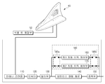
도 3은 샤크핀 안테나와 마이크로폴 안테나가 장착되는 공용 베이스 프레임을 설명하기 위한 도면이다.
도 4는 샤크핀 안테나의 세부 구성을 나타내는 도면이다.
도 5는 차량용 교체형 안테나의 세부 구성을 나타내는 도면이다.
도 6 및 도 7은 안테나 타입별 자동 이득제어를 수행하는 방법을 설명하기 위한 회로도이다.
도 8은 샤크핀 안테나가 장착된 경우의 차량용 교체형 안테나의 신호 처리 방법을 설명하기 위한 도면이다.
도 9는 마이크로폴 안테나가 장착된 경우의 차량용 교체형 안테나의 신호 처리 방법을 설명하기 위한 도면이다.1 is a view showing the appearance of a vehicle equipped with a micropole antenna.
2 is a view showing an appearance of a vehicle equipped with a shark pin antenna.
3 is a view for explaining a common base frame on which a shakepin antenna and a micropole antenna are mounted.
4 is a view showing a detailed configuration of a shark pin antenna.
5 is a view showing a detailed configuration of a vehicle-use replaceable antenna.
6 and 7 are circuit diagrams for explaining a method of performing automatic gain control for each antenna type.
Fig. 8 is a diagram for explaining a signal processing method of a vehicle replaceable antenna when a shakepin antenna is mounted. Fig.
Fig. 9 is a view for explaining a signal processing method of a vehicle replaceable antenna when a micropole antenna is mounted. Fig.
본 발명의 목적, 특정한 장점들 및 신규한 특징들은 첨부된 도면들과 연관되는 이하의 상세한 설명과 바람직한 실시예들로부터 더욱 명백해질 것이다. 본 명세서에서 각 도면의 구성요소들에 참조번호를 부가함에 있어서, 동일한 구성 요소들에 한해서는 비록 다른 도면상에 표시되더라도 가능한 한 동일한 번호를 가지도록 하고 있음에 유의하여야 한다. 또한, 본 발명을 설명함에 있어서, 관련된 공지 기술에 대한 구체적인 설명이 본 발명의 요지를 불필요하게 흐릴 수 있다고 판단되는 경우 그 상세한 설명은 생략한다. 본 명세서에서, 제1, 제2 등의 용어는 하나의 구성요소를 다른 구성요소로부터 구별하기 위해 사용되는 것으로, 구성요소가 상기 용어들에 의해 제한되는 것은 아니다.BRIEF DESCRIPTION OF THE DRAWINGS The objectives, specific advantages, and novel features of the present invention will become more apparent from the following detailed description taken in conjunction with the accompanying drawings, in which: FIG. It should be noted that, in the present specification, the reference numerals are added to the constituent elements of the drawings, and the same constituent elements are assigned the same number as much as possible even if they are displayed on different drawings. In the following description, well-known functions or constructions are not described in detail since they would obscure the invention in unnecessary detail. In this specification, the terms first, second, etc. are used to distinguish one element from another, and the element is not limited by the terms.
이하, 첨부된 도면을 참조하여 본 발명의 바람직한 실시형태를 상세히 설명하기로 한다.Hereinafter, preferred embodiments of the present invention will be described in detail with reference to the accompanying drawings.
도 1은 마이크로폴 안테나가 장착된 차량의 외관을 도시하는 도면이고, 도 2는 샤크핀 안테나가 장착된 차량의 외관을 도시하는 도면이다.Fig. 1 is a view showing the appearance of a vehicle equipped with a micropole antenna, and Fig. 2 is a view showing the appearance of a vehicle equipped with a shark pin antenna.
이하에서는, 샤크핀 안테나와 마이크로폴 안테나가 장착되는 공용 베이스 프레임을 설명하기 위한 도 3 및 샤크핀 안테나의 세부 구성을 나타내는 도 4를 참조하여 설명하기로 한다.Hereinafter, FIG. 3 for explaining a common base frame to which the shark pin antenna and the micropole antenna are mounted, and the shark pin antenna will be described with reference to FIG. 4 showing the detailed structure of the antenna.
또한, 설명의 편의를 위해 마이크로폴 안테나를 제1 안테나라고 하고, 샤크핀 안테나를 제2 안테나로 칭하기로 한다.For convenience of explanation, the micropole antenna will be referred to as a first antenna and the shark pin antenna will be referred to as a second antenna.
도 1 및 도 2를 참조하면, 차량(1)의 외관은 차량(1)의 외관을 형성하는 본체(10), 운전자에게 차량(1) 전방의 시야를 제공하는 윈드 스크린(windscreen)(11), 운전자에게 차량(1) 후방의 시야를 제공하는 사이드 미러(12), 차량(1) 내부를 외부로부터 차폐시키는 도어(13) 및 차량의 전방에 위치하는 앞바퀴(21), 차량의 후방에 위치하는 뒷바퀴(22)를 포함하여 차량(1)을 이동시키기 위한 바퀴를 포함할 수 있다.1 and 2, an appearance of a
윈드 스크린(11)은 본체(10)의 전방 상측에 마련되어 차량(1) 내부의 운전자가 차량(1) 전방의 시각 정보를 획득할 수 있도록 한다. 또한, 사이드 미러(12)는 본체(10)의 좌측에 마련되는 좌측 사이드 미러 및 우측에 마련되는 우측 사이드 미러를 포함하며, 차량(1) 내부의 운전자가 차량(1) 측면 및 후방의 시각 정보를 획득할 수 있도록 한다.The
도어(13)는 본체(10)의 좌측 및 우측에 회동 가능하게 마련되어 개방 시에 운전자가 차량(1)의 내부에 탑승할 수 있도록 하며, 폐쇄 시에 차량(1)의 내부를 외부로부터 차폐시킬 수 있다. The
또한, 차량(1)은 루프 상에 안테나를 장착할 수 있다. 이때, 안테나는 마이크로폴 안테나(Micropole Antenna)인 제1 안테나(도 1의 30), 샤크핀 안테나(Shark Fin Type Antenna)인 제2 안테나(도 2의 40)일 수 있다.Further, the
개시되는 발명의 안테나는 차량용 교체형 안테나로, 하나의 공용 베이스(50) 상에 제1 안테나(30)와 제2 안테나(40)를 교체하여 사용할 수 있다. 이를 위해, 공용 베이스(50)에 장착된 안테나의 타입을 판단하고, 판단된 안테나의 임피던스에 최적화된 이득 제어(Gain Control)를 수행할 수 있도록 하는 수신 회로부를 구비할 수 있으며, 이에 대한 상세 내용은 후술하기로 한다.The antenna of the disclosed invention is a vehicle-replaceable antenna, and the
제1 및 제2 안테나(30, 40)는 차량(1) 내 구비되어 운전자의 조작 명령에 따라 경로 안내 정보를 비롯하여 오디오 기능, 비디오 기능 및 TV 기능 등을 제공하기 위한 AVN 장치(25)와 연결될 수 있다.The first and
도 3에서 도시하는 바와 같이, 제1 안테나(30)는 FM 헤리컬(FM Helical), LTE/V2X 헤리컬(LTE/V2X Helical)과 공용화된 피딩(feeding) 구조가 케이스와 일체형으로 조립된 구조이다.3, the
또한, 제2 안테나(40)는 FM/LTE/V2X 안테나 패턴과 공용화된 피딩(feeding) 구조가 케이스와 일체형으로 조립된 구조이다.In addition, the
상술한 제1 및 제2 안테나(30, 40)는 AM/FM 신호, DBM 신호, LTE/3G 신호, GPS 신호, SXM 신호, DAB 신호, eCall 신호, GNSS 신호 및 Baidu 신호 중 적어도 하나 이상을 수신할 수 있다.The first and
공용 베이스(50)는 LNA(Low Noise Amplifier) 모듈단과 급전부를 형성하여 케이스와 일체형인 상술한 제1 안테나(30)와 제2 안테나(40)만을 결합함에 따라 다양한 형태의 안테나를 구현할 수 있도록 하는 것이다. The
이때, 공용 베이스(50)는 위성항법안테나인 GNSS(Global Navigation Satellite System) 패치 안테나, 위성방송안테나인 SXM 패치 안테나, AM/FM/GNSS/SXM의 LNA, 제1 안테나(30)와 제2 안테나(40)를 교체하여 공용으로 급전할 수 있는 구조를 탑재한다.At this time, the
도 3에서 개시하는 바와 같이, 동일한 공용 베이스(50)에 제1 안테나(30)와 제2 안테나(40)가 모두 장착되는 것이 가능하다. 이를 위해, 공용 베이스(50)의 장착면의 형상은 마이크폴 안테나 타입의 제1 안테나(30)의 케이스와 샤크핀 안테나 타입의 제2 안테나(40)의 케이스에 대응되는 형상으로 이루어질 수 있다.It is possible to mount both the
또한, 제1 안테나(30)와 제2 안테나(40)의 케이스 중 공용 베이스(50)에 장착되는 부분은 서로 동일한 형상으로 이루어질 수 있다.In addition, the
샤크핀 안테나를 예로 들은 도 4를 참조하면, 제2 안테나(40)는 상어 등지느러미를 연상시키는 형상의 안테나 케이스(41), 특정 주파수 대역의 신호를 수신하기 위한 안테나 유닛(43), 회로기판(45), 제2 안테나임을 식별하기 위한 식별 핀(ID Pin)(46) 및 RF 핀(47)을 포함할 수 있다.4, which illustrates a shark pin antenna, the
이때, 안테나 유닛(43)은 거치대와 거치대 외면을 권회하는 코일로 구성되어 회로기판(45)과 결합되어 공용 베이스(60)에 장착될 수 있다. 예를 들어, 안테나 유닛(43)은 라디오 주파수 대역의 신호를 수신하기 위한 것일 수 있다.At this time, the
식별 핀(46)과 RF 핀(47)은 공용 베이스(50)에 구비된 식별 핀 체결부(53)와 RF 핀 체결부(55)를 통해 각각 체결될 수 있다. 이때, 식별 핀(46)은 제2 안테나(40)를 검출(Detecting)하기 위한 핀을 의미하고, RF 핀(47)은 안테나의 RF 신호의 피딩 핀(Feeding Pin)을 의미한다. The
상기 RF 핀(47)은 제2 안테나(40)뿐만 아니라 제1 안테나(30)에도 구비되어 있어, 제1 안테나(30) 장착시 동일하게 RF 핀 체결부(55)에 체결될 수 있다.The
한편, 식별 핀(46)은 제2 안테나(40)를 검출하기 위한 것이 아니라, 제1 안테나(30)를 검출하기 위한 핀으로 제1 안테나(30)에 구비되는 것도 가능하다 할 것이다. 이러한 경우, 제2 안테나(40)에는 식별 핀(46)이 생략된다. The
도 5는 차량용 교체형 안테나의 세부 구성을 나타내는 도면이다.5 is a view showing a detailed configuration of a vehicle-use replaceable antenna.
이하에서는, 샤크핀 안테나의 세부 구성을 나타내는 도 4, 안테나 타입별 자동 이득제어를 수행하는 방법을 설명하기 위한 회로도인 도 6 및 도 7를 참조하여 설명하기로 한다.Hereinafter, FIG. 4 illustrating a detailed configuration of the shakepin antenna, and a circuit diagram for explaining a method of performing automatic gain control for each antenna type will be described with reference to FIGS. 6 and 7. FIG.
또한, 샤크핀 안테나가 장착된 경우의 차량용 교체형 안테나의 신호 처리 방법을 설명하기 위한 도 8, 마이크로폴 안테나가 장착된 경우의 차량용 교체형 안테나의 신호 처리 방법을 설명하기 위한 도 9를 참조하여 설명하기로 한다.8 for describing a signal processing method of a vehicle replaceable antenna when a shakepin antenna is mounted, and Fig. 9 for explaining a signal processing method of a vehicle replaceable antenna in a case where a micropole antenna is mounted I will explain.
도 4 및 도 5에서 도시하는 바와 같이, 차량용 교체형 안테나는 안테나 케이스(41)와 결합되는 장착면(51)이 형성된 공용 베이스(50), 장착면(51)에 형성된 식별 핀 체결부(53) 및 식별 핀 체결부(53)에 식별 핀이 체결되는지 여부에 따라 안테나 타입을 판단하여 판단된 안테나 타입에 대응되는 임피던스의 이득으로 자동 제어하는 수신 회로부(100)를 포함할 수 있다.4 and 5, the vehicle replaceable antenna includes a
상기 안테나 타입은 서로 다른 이득제어(Gain Control) 특성을 가지는 제1 안테나 및 제2 안테나 중 어느 하나일 수 있다.The antenna type may be any one of a first antenna and a second antenna having different gain control characteristics.
예를 들어, 제1 안테나(30)는 마이크로폴 안테나이고, 제2 안테나(40)는 샤크핀 안테나일 수 있다.For example, the
도 3에서 도시하는 바와 같이, 제1 안테나(30)의 케이스 및 제2 안테나(40)의 케이스는 공용 베이스(50)의 장착면(51)과 체결되는 영역이 서로 동일한 형상으로 이루어질 수 있다. 이러한 구조로 인해, 동일한 공유 베이스(50)에 제1 안테나(30) 및 제2 안테나(40)를 교체하여 장착할 수 있는 것이다.3, the case of the
상술한 수신 회로부(100)는 안테나 급전점(110), 인덕터(120), 필터부(130), 임피던스 정합 회로(140), 증폭부(150), 제1 자동이득제어부(160), 제2 자동이득제어부(170) 및 스위치(180)를 포함할 수 있다. 이때, 수신 회로부(100)는 RF 수신 회로이다.The receiving
필터부(130)는 안테나 급전점(110)을 통해 수신된 신호를 필터링하기 위한 구성일 수 있다. 이때, 필터부(130)는 대역 차단 필터(Band Reject Filter)로 이루어질 수 있다.The
또한, 안테나 급전점(110)은 제1 안테나(30)의 RF 신호 또는 제2 안테나(40)의 RF 신호를 공통으로 수신할 수 있다. 즉, 공용 베이스(50)에 제1 안테나(30)가 장착되거나, 또는 제2 안테나(40)가 장착되는 경우에도 RF 신호는 안테나 급전점(110)으로 급전된다는 것이다.The
임피던스 정합 회로(140)는 필터부(130)와 직렬로 연결되어 임피던스 정합과 매칭을 수행하기 위한 구성일 수 있다.The
증폭부(150)는 임피던스 정합 회로(140)와 직렬로 연결되어 신호를 증폭하기 위한 구성일 수 있다.The amplifying
도 5에서 도시하는 바와 같이, 임피던스 정합 회로(140)와 증폭부(150)의 직렬 회로는 제1 자동이득제어부(160)와 제2 자동이득제어부(170) 각각과 병렬로 연결된다.5, the series circuit of the
제1 자동이득제어부(160)는 제1 안테나(30)에 대응되는 임피던스의 이득으로 자동 제어하기 위한 구성일 수 있다.The first automatic
제2 자동이득제어부(170)는 제1 자동이득제어부(160)와 병렬로 연결되어, 제2 안테나(40)에 대응되는 임피던스의 이득으로 자동 제어하기 위한 구성일 수 있다.The second automatic
제2 자동이제어부(160)는 AM/FM 신호 및 CMMB(China Mobile Multimedia Broadcasting) 신호를 비롯한 복수의 신호 중 적어도 하나의 신호의 세기에 기초하여 이득을 자동으로 제어할 수 있다.The second
샤크핀 타입 안테나의 라디오 패시브(Passive) 성능은 마이크로폴 타입 안테나의 라디오 패시브(Passive) 성능 보다 낮아 서로 다른 이득제어(gain control) 회로가 적용되어야 하는데, 개시된 발명에서는 공용 베이스(50)에 장착되는 안테나 타입을 판단하는 것이 가능하기 때문에, 장착된 안테나 타입에 대응되는 자동이득제어가 이루어질 수 있는 것이다. 이에, 하나의 공용 베이스(50)에 다양한 타입의 안테나를 교체 적용할 수 있는 것이다.The passive performance of the shank pin type antenna is lower than the passive performance of the micropole type antenna, so that a different gain control circuit should be applied. In the disclosed invention, Since it is possible to determine the antenna type, automatic gain control corresponding to the mounted antenna type can be performed. Accordingly, various types of antennas can be alternatively applied to one
스위치(180)는 식별 핀 체결부(53)에 식별 핀(46)이 체결되는지 여부에 따라 제1 자동이득제어부(160) 및 제2 자동이득제어부(170) 중 어느 하나를 온(On) 시키는 구성일 수 있다.The
만약, 식별 핀(46)이 제1 안테나용 식별 핀인 경우, 식별 핀 체결부(53)에 식별 핀이 체결되면, 스위치(180)는 제1 자동이득제어부(160)를 온(On) 시킬 수 있다.If the
또한, 식별 핀(46)이 제2 안테나용 식별 핀인 경우, 식별 핀 체결부(53)에 식별 핀이 체결되면, 스위치(180)는 제2 자동이득제어부(170)를 온(On) 시킬 수 있다. When the
즉, 안테나 타입을 판단하기 위한 식별 핀(46)은 특정 사양의 안테나에 설치되는 것에 한정되지 않고, 복수의 안테나 중 각각을 구분하기 위해 운용자의 필요에 따라 특정 안테나에 설치될 수 있다. 이때, 식별 핀을 통한 안테나 타입 파악 결과에 따라, 스위치(180)가 해당 자동이득제어부를 온(On) 시키도록 회로 설계를 구성함은 당연하다 할 것이다.That is, the
도 6은 도 5의 스위치(180)와 제1 및 제2 자동이득제어부(160, 170)의 구조를 보다 상세하게 나타내는 도면이다.6 is a diagram illustrating the structure of the
도 5 및 도 6에서 도시하는 바와 같이, 스위치(180)는 제1 자동이득제어부(160)와 제2 자동이득제어부(170)의 병렬회로의 선단과 후단에 각각 직렬 연결된 제1 스위치(180a)와 제2 스위치(180b)를 포함할 수 있다.5 and 6, the
도 6에서 도시하는 바와 같이, 스위치(180)는 SPDT(Single Pole Double Throw) 스위치일 수 있다. 이러한 스위치가 적용됨에 따라, 도 7의 식별 핀 체결부(53)에 식별 핀(46)이 체결되는지 여부에 따라, 스위치(180)가 구동하는 것이다.As shown in FIG. 6, the
도 7을 참조하면, 식별 핀 체결부(53)에 식별 핀(46)이 체결되면, V1은 로우(Low, L), V2는 하이(High, H)로 전환함에 따라, 도 6의 스위치(180a, 180b)가 제2 선로(J2)를 연결시켜 제2 자동이득제어부(170)를 동작시킬 수 있다. 이때, 식별 핀(46)은 샤크핀 안테나 형태의 제2 안테나(40)를 검출하기 위한 경우일 수 있다.Referring to FIG. 7, when the
만약, 식별 핀 체결부(53)에 식별 핀(46)이 체결되지 않은 경우, V1은 하이(High, H)로, V2는 로우(Low, L)로 전환하고, 도 6의 스위치(180)는 제1 선로(J1)를 연결시켜 제1 자동이득제어부(160)를 동작시킬 수 있다.If the
표 1 및 표 2는 제1 안테나(30)가 마이크로폴 안테나이고, 제2 안테나(40)가 샤크핀 안테나이며, 식별 핀(46)이 샤크핀 안테나를 식별하기 위해 샤크핀 안테나에 장착된 경우를 예로 들어 나타내는 것이다. Tables 1 and 2 show the case where the
도 9와 같이, 공용 베이스(50)에 마이크로폴 안테나가 장착된 경우, 식별 핀 체결부(53)는 스위치의 오픈(Open)된 상태와 같아 V1은 하이(High, H), V2는 로우(Low, L) 상태(표1 참조)가 되어, 제1 선로(Com-J1)가 연결상태로 전환(표2 참조)함에 따라 마이크폴 안테나의 임피던스에 최적화된 자동이득경로로 연결(제1 자동이득제어부(160) 연결)되는 것이다.9, when the micropole antenna is mounted on the
도 8과 같이, 공용 베이스(50)에 샤크핀 안테나가 장착된 경우, 식별 핀 체결부(53)는 스위치의 닫힌(Close) 상태와 같아 V1은 로우(Low, L), V2는 하이(High, H) 상태(표1 참조)가 되어, 제2 선로(Com-J2)가 연결상태로 전환(표2 참조)함에 따라 샤크핀 안테나의 임피던스에 최적화된 자동이득경로로 연결(제2 자동이득제어부(170) 연결)되는 것이다.8, when the shank pin antenna is mounted on the
상술한 바와 같이, 개시되는 발명은 공용 베이스에 장착되는 안테나 타입을 능동적으로 파악할 수 있기 때문에, 각각의 안테나 타입에 따른 임피던스에 최적화된 이득 제어를 수행할 수 있다는 효과를 기대할 수 있다. 또한, 안테나 케이스와 공용 베이스의 장착 부분을 서로 동일한 형상으로 형성하여, 하나의 공용 베이스를 이용하여 다양한 안테나를 교체 사용할 수 있다.As described above, since the disclosed invention can actively grasp the antenna type mounted on the common base, it is expected that the gain control optimized for the impedance according to each antenna type can be performed. Further, the antenna case and the mounting portion of the common base may be formed in the same shape so that various antennas can be used by using one common base.
이상 본 발명을 구체적인 실시예를 통하여 상세히 설명하였으나, 이는 본 발명을 구체적으로 설명하기 위한 것으로, 본 발명은 이에 한정되지 않으며, 본 발명의 기술적 사상 내에서 당 분야의 통상의 지식을 가진 자에 의해 그 변형이나 개량이 가능함이 명백하다.While the present invention has been particularly shown and described with reference to exemplary embodiments thereof, it is to be understood that the same is by way of illustration and example only and is not to be construed as limiting the present invention. It is obvious that the modification or improvement is possible.
본 발명의 단순한 변형 내지 변경은 모두 본 발명의 영역에 속하는 것으로 본 발명의 구체적인 보호 범위는 첨부된 특허청구범위에 의하여 명확해질 것이다.It will be understood by those skilled in the art that various changes in form and details may be made therein without departing from the spirit and scope of the invention as defined by the appended claims.
1 : 차량
30 : 제1 안테나
40 : 제2 안테나
50 : 공용 베이스
100 : 수신 회로부
110 : 안테나 급전점
120 : 인덕터
130 : 필터부
140 : 임피던스 정합 회로
150 : 증폭부
160 : 제1 자동이득제어부
170 : 제2 자동이득제어부
180, 180a, 180b : 스위치1: vehicle
30: first antenna
40: second antenna
50: common base
100: receiving circuit
110: antenna feed point
120: inductor
130:
140: Impedance matching circuit
150:
160: first automatic gain control section
170: second automatic gain control section
180, 180a, 180b: switch
Claims (22)
상기 장착면에 형성된 식별 핀 체결부; 및
상기 식별 핀 체결부에 식별 핀이 체결되는지 여부에 따라 안테나 타입을 판단하여 판단된 안테나 타입에 대응되는 임피던스의 이득으로 자동 제어하는 수신 회로부;
를 포함하는 차량용 교체형 안테나.
A common base formed with a mounting surface to be coupled to the antenna case;
An identification pin fastening portion formed on the mounting surface; And
A reception circuit for automatically determining the antenna type according to whether or not the identification pin is fastened to the identification pin fastening part, and automatically controlling the antenna type according to the gain of the impedance corresponding to the determined antenna type;
And an antenna for a vehicle.
상기 안테나 타입은 서로 다른 이득제어(Gain Control) 특성을 가지는 제1 안테나 및 제2 안테나 중 어느 하나인 차량용 교체형 안테나.
The method according to claim 1,
Wherein the antenna type is any one of a first antenna and a second antenna having different gain control characteristics.
상기 수신 회로부는,
상기 제1 안테나에 대응되는 임피던스의 이득으로 자동 제어하기 위한 제1 자동이득제어부;
상기 제1 자동이득제어부와 병렬로 연결되어, 상기 제2 안테나에 대응되는 임피던스의 이득으로 자동 제어하기 위한 제2 자동이득제어부; 및
상기 식별 핀 체결부에 상기 식별 핀이 체결되는지 여부에 따라 상기 제1 자동이득제어부 및 상기 제2 자동이득제어부 중 어느 하나를 온(On) 시키는 스위치;
를 포함하는 차량용 교체형 안테나.
3. The method of claim 2,
The receiving circuit unit,
A first automatic gain controller for automatically controlling the gain of the impedance corresponding to the first antenna;
A second automatic gain control unit connected in parallel with the first automatic gain control unit to automatically control a gain of the impedance corresponding to the second antenna; And
A switch for turning on either the first automatic gain control unit or the second automatic gain control unit depending on whether the identification pin is fastened to the identification pin coupling unit;
And an antenna for a vehicle.
상기 식별 핀이 제1 안테나용 식별 핀인 경우,
상기 식별 핀 체결부에 상기 식별 핀이 체결되면, 상기 스위치는 상기 제1 자동이득제어부를 온(On) 시키는 차량용 교체형 안테나.
The method of claim 3,
When the identification pin is the identification pin for the first antenna,
And the switch turns on the first automatic gain control unit when the identification pin is coupled to the identification pin coupling unit.
상기 식별 핀이 제2 안테나용 식별 핀인 경우,
상기 식별 핀 체결부에 상기 식별 핀이 체결되면, 상기 스위치는 상기 제2 자동이득제어부를 온(On) 시키는 차량용 교체형 안테나.
The method of claim 3,
When the identification pin is the identification pin for the second antenna,
And the switch turns on the second automatic gain control unit when the identification pin is coupled to the identification pin locking unit.
상기 스위치는 상기 제1 자동이득제어부와 상기 제2 자동이득제어부의 병렬회로의 선단과 후단에 각각 직렬 연결된 제1 스위치와 제2 스위치를 포함하는 차량용 교체형 안테나.
The method of claim 3,
Wherein the switch includes a first switch and a second switch connected in series at the front end and the rear end of the parallel circuit of the first automatic gain control section and the second automatic gain control section, respectively.
상기 스위치는 SPDT(Single Pole Double Throw) 스위치인 차량용 교체형 안테나.
The method of claim 3,
Wherein the switch is a single pole double throw (SPDT) switch.
상기 수신 회로부는,
안테나 급전점을 통해 수신된 신호를 필터링하기 위한 필터부;
상기 필터부와 직렬로 연결되어 임피던스 정합과 매칭을 수행하기 위한 임피던스 정합 회로; 및
상기 임피던스 정합 회로와 직렬로 연결되어 신호를 증폭하기 위한 증폭부;
를 더 포함하는 차량용 교체형 안테나.
The method of claim 3,
The receiving circuit unit,
A filter unit for filtering a signal received through the antenna feed point;
An impedance matching circuit connected in series with the filter unit to perform impedance matching and matching; And
An amplifier connected in series with the impedance matching circuit to amplify a signal;
Further comprising: an antenna for a vehicle.
상기 임피던스 정합 회로와 상기 증폭부의 직렬 회로는 상기 제1 자동이득제어부와 상기 제2 자동이득제어부 각각과 병렬로 연결된 차량용 교체형 안테나.
9. The method of claim 8,
And the series circuit of the impedance matching circuit and the amplifying unit is connected in parallel with the first automatic gain control unit and the second automatic gain control unit, respectively.
상기 필터부는 대역 차단 필터(Band Reject Filter)로 이루어진 차량용 교체형 안테나.
9. The method of claim 8,
Wherein the filter unit comprises a band reject filter.
상기 안테나 급전점은 상기 제1 안테나의 RF 신호 또는 상기 제2 안테나의 RF 신호를 공통으로 수신하는 차량용 교체형 안테나.
9. The method of claim 8,
Wherein the antenna feed point commonly receives the RF signal of the first antenna or the RF signal of the second antenna.
상기 수신 회로부는, RF 수신 회로인 차량용 교체형 안테나.
The method of claim 3,
Wherein the receiving circuit unit is an RF receiving circuit.
상기 제1 안테나의 케이스 및 상기 제2 안테나의 케이스는 상기 공용 베이스의 장착면과 체결되는 영역이 서로 동일한 형상으로 이루어진 차량용 교체형 안테나.
3. The method of claim 2,
Wherein the case of the first antenna and the case of the second antenna have the same shape in the region where the mounting surface of the common base is fastened.
상기 차량용 교체형 안테나는,
안테나 케이스와 결합되는 장착면이 형성된 공용 베이스;
상기 장착면에 형성된 식별 핀 체결부; 및
상기 식별 핀 체결부에 식별 핀이 체결되는지 여부에 따라 안테나 타입을 판단하여 판단된 안테나 타입에 대응되는 임피던스의 이득으로 자동 제어하는 수신 회로부;
를 포함하는 차량용 교체형 안테나를 구비하는 차량.
In a vehicle having a vehicle-mounted antenna,
The vehicle replaceable antenna includes:
A common base formed with a mounting surface to be coupled to the antenna case;
An identification pin fastening portion formed on the mounting surface; And
A reception circuit for automatically determining the antenna type according to whether or not the identification pin is fastened to the identification pin fastening part, and automatically controlling the antenna type according to the gain of the impedance corresponding to the determined antenna type;
And a vehicle-mounted antenna.
상기 안테나 타입은 서로 다른 이득제어(Gain Control) 특성을 가지는 제1 안테나 및 제2 안테나 중 어느 하나인 차량용 교체형 안테나를 구비하는 차량.
15. The method of claim 14,
Wherein the antenna type comprises a vehicle-replaceable antenna that is one of a first antenna and a second antenna having different gain control characteristics.
상기 수신 회로부는,
상기 제1 안테나에 대응되는 임피던스의 이득으로 자동 제어하기 위한 제1 자동이득제어부;
상기 제1 자동이득제어부와 병렬로 연결되어, 상기 제2 안테나에 대응되는 임피던스의 이득으로 자동 제어하기 위한 제2 자동이득제어부; 및
상기 식별 핀 체결부에 상기 식별 핀이 체결되는지 여부에 따라 상기 제1 자동이득제어부 및 상기 제2 자동이득제어부 중 어느 하나를 온(On) 시키는 스위치;
를 포함하는 차량용 교체형 안테나를 구비하는 차량.
16. The method of claim 15,
The receiving circuit unit,
A first automatic gain controller for automatically controlling the gain of the impedance corresponding to the first antenna;
A second automatic gain control unit connected in parallel with the first automatic gain control unit to automatically control a gain of the impedance corresponding to the second antenna; And
A switch for turning on either the first automatic gain control unit or the second automatic gain control unit depending on whether the identification pin is fastened to the identification pin coupling unit;
And a vehicle-mounted antenna.
상기 식별 핀이 제1 안테나용 식별 핀인 경우,
상기 식별 핀 체결부에 상기 식별 핀이 체결되면, 상기 스위치는 상기 제1 자동이득제어부를 온(On) 시키는 차량용 교체형 안테나를 구비하는 차량.
17. The method of claim 16,
When the identification pin is the identification pin for the first antenna,
And a switchable antenna for a vehicle that turns on the first automatic gain control unit when the identification pin is fastened to the identification pin locking unit.
상기 식별 핀이 제2 안테나용 식별 핀인 경우,
상기 식별 핀 체결부에 상기 식별 핀이 체결되면, 상기 스위치는 상기 제2 자동이득제어부를 온(On) 시키는 차량용 교체형 안테나를 구비하는 차량.
17. The method of claim 16,
When the identification pin is the identification pin for the second antenna,
And a switchable antenna for a vehicle which turns on the second automatic gain control section when the identification pin is fastened to the identification pin coupling section.
상기 스위치는 상기 제1 자동이득제어부와 상기 제2 자동이득제어부의 병렬회로의 선단과 후단에 각각 직렬 연결된 제1 스위치와 제2 스위치를 포함하는 차량용 교체형 안테나를 구비하는 차량.
17. The method of claim 16,
Wherein the switch includes a vehicle-replaceable antenna including a first switch and a second switch connected in series at the front end and the rear end of the parallel circuit of the first automatic gain control section and the second automatic gain control section, respectively.
상기 수신 회로부는,
안테나 급전점을 통해 수신된 신호를 필터링하기 위한 필터부;
상기 필터부와 직렬로 연결되어 임피던스 정합과 매칭을 수행하기 위한 임피던스 정합 회로; 및
상기 임피던스 정합 회로와 직렬로 연결되어 신호를 증폭하기 위한 증폭부;
를 더 포함하는 차량용 교체형 안테나를 구비하는 차량.
17. The method of claim 16,
The receiving circuit unit,
A filter unit for filtering a signal received through the antenna feed point;
An impedance matching circuit connected in series with the filter unit to perform impedance matching and matching; And
An amplifier connected in series with the impedance matching circuit to amplify a signal;
Further comprising a vehicle interchangeable antenna.
임피던스 정합과 매칭을 수행하기 위한 임피던스 정합 회로,
신호를 증폭하기 위한 증폭부,
서로 다른 이득제어 특성을 가지는 제1 안테나 및 제2 안테나 중 어느 하나를 식별하기 위한 식별 신호가 발생함에 따라 제1 자동이득제어부 및 제2 자동이득제어부 중 어느 하나를 온(On)시키는 스위치,
제1 안테나에 대응되는 임피던스의 이득으로 자동 제어하기 위한 제1 자동이득제어부, 및
제2 안테나에 대응되는 임피던스의 이득으로 자동 제어하기 위한 제2 자동이득제어부를 포함하는 수신 회로부를 포함하고,
상기 제1 자동이득제어부와 상기 제2 자동이득제어부는 상기 임피던스 정합 회로와 상기 증폭부의 직렬회로에 각각 병렬로 연결되는 차량용 교체형 안테나.A filter unit for filtering the signal received through the antenna feed point,
An impedance matching circuit for performing impedance matching and matching,
An amplifier for amplifying the signal,
A switch for turning on any one of the first automatic gain control unit and the second automatic gain control unit as an identification signal for identifying any one of the first antenna and the second antenna having different gain control characteristics is generated,
A first automatic gain control section for automatically controlling the gain of the impedance corresponding to the first antenna,
And a second automatic gain control section for automatically controlling the gain of the impedance corresponding to the second antenna,
Wherein the first automatic gain control unit and the second automatic gain control unit are connected in parallel to the impedance matching circuit and the series circuit of the amplifying unit, respectively.
Priority Applications (1)
| Application Number | Priority Date | Filing Date | Title |
|---|---|---|---|
| KR1020150097141A KR101675309B1 (en) | 2015-07-08 | 2015-07-08 | Replaceable antenna for vehicle and vehicle having the same |
Applications Claiming Priority (1)
| Application Number | Priority Date | Filing Date | Title |
|---|---|---|---|
| KR1020150097141A KR101675309B1 (en) | 2015-07-08 | 2015-07-08 | Replaceable antenna for vehicle and vehicle having the same |
Publications (1)
| Publication Number | Publication Date |
|---|---|
| KR101675309B1 true KR101675309B1 (en) | 2016-11-11 |
Family
ID=57527698
Family Applications (1)
| Application Number | Title | Priority Date | Filing Date |
|---|---|---|---|
| KR1020150097141A Active KR101675309B1 (en) | 2015-07-08 | 2015-07-08 | Replaceable antenna for vehicle and vehicle having the same |
Country Status (1)
| Country | Link |
|---|---|
| KR (1) | KR101675309B1 (en) |
Citations (4)
| Publication number | Priority date | Publication date | Assignee | Title |
|---|---|---|---|---|
| JP2004363747A (en) * | 2003-06-03 | 2004-12-24 | Mitsumi Electric Co Ltd | Antenna device |
| KR20100122846A (en) * | 2008-03-12 | 2010-11-23 | 가부시키가이샤 비트 소닉 | Substitute antenna |
| KR20130065485A (en) * | 2011-12-09 | 2013-06-19 | 엘지이노텍 주식회사 | Reveiver with lna and input signal processing method thereof |
| JP2014057126A (en) * | 2012-09-11 | 2014-03-27 | Beat Sonic:Kk | Replacement antenna for vehicle |
-
2015
- 2015-07-08 KR KR1020150097141A patent/KR101675309B1/en active Active
Patent Citations (4)
| Publication number | Priority date | Publication date | Assignee | Title |
|---|---|---|---|---|
| JP2004363747A (en) * | 2003-06-03 | 2004-12-24 | Mitsumi Electric Co Ltd | Antenna device |
| KR20100122846A (en) * | 2008-03-12 | 2010-11-23 | 가부시키가이샤 비트 소닉 | Substitute antenna |
| KR20130065485A (en) * | 2011-12-09 | 2013-06-19 | 엘지이노텍 주식회사 | Reveiver with lna and input signal processing method thereof |
| JP2014057126A (en) * | 2012-09-11 | 2014-03-27 | Beat Sonic:Kk | Replacement antenna for vehicle |
Similar Documents
| Publication | Publication Date | Title |
|---|---|---|
| US8294625B2 (en) | Antenna diversity system | |
| US5973648A (en) | Radio antenna arrangement with a patch antenna for mounting on or adjacent to the windshield of a vehicle | |
| EP3270460B1 (en) | Shark fin antenna comprising vehicle-type v2x communication system | |
| US8483749B2 (en) | Mobile terminal device for receiving dual band signal using multiple resonance antenna | |
| US7609216B2 (en) | Vehicle mirror housing antenna assembly | |
| WO2002075942A3 (en) | Concurrent dual-band receiver architecture | |
| US20070182626A1 (en) | Combined Antenna Module with Single Output | |
| US20100033398A1 (en) | Modular active antenna for receiving multiple broadcasting signals | |
| US6989785B2 (en) | Low-profile, multi-band antenna module | |
| CN107171758A (en) | Vehicular communication system | |
| KR102038558B1 (en) | Antenna device for vehicle | |
| KR101675309B1 (en) | Replaceable antenna for vehicle and vehicle having the same | |
| WO2008076496A2 (en) | Multi-frequency antenna assemblies with dc switching | |
| KR101108143B1 (en) | Car audio system with integrated module of tuner and active antenna | |
| JP4466750B2 (en) | Vehicle antenna device | |
| US20080090514A1 (en) | Method and system for processing GPS and satellite digital radio signals using a shared LNA | |
| KR20180042744A (en) | Module Integrated Antenna System For Vehicle | |
| KR20100003075U (en) | Rear View Camera-Mounted Vehicle Exterior Antenna Unit | |
| US20090080559A1 (en) | Antenna diversity by means of its through connection for receivers of digital radio signals | |
| EP3840120A1 (en) | Antenna apparatus for vehicles, and method of receiving broadcasting by using the antenna apparatus | |
| JP2001102836A5 (en) | ||
| CN110730016A (en) | Satellite signal retransmission device | |
| JP2004048376A (en) | Glass antenna device for automobile | |
| US20060116071A1 (en) | Receiver integrated satellite digital audio radio antenna system | |
| KR20180109544A (en) | Internal intergrated antenna apparatus for vehicle |
Legal Events
| Date | Code | Title | Description |
|---|---|---|---|
| PA0109 | Patent application |
St.27 status event code: A-0-1-A10-A12-nap-PA0109 |
|
| PA0201 | Request for examination |
St.27 status event code: A-1-2-D10-D11-exm-PA0201 |
|
| R18-X000 | Changes to party contact information recorded |
St.27 status event code: A-3-3-R10-R18-oth-X000 |
|
| PE0902 | Notice of grounds for rejection |
St.27 status event code: A-1-2-D10-D21-exm-PE0902 |
|
| E13-X000 | Pre-grant limitation requested |
St.27 status event code: A-2-3-E10-E13-lim-X000 |
|
| P11-X000 | Amendment of application requested |
St.27 status event code: A-2-2-P10-P11-nap-X000 |
|
| P13-X000 | Application amended |
St.27 status event code: A-2-2-P10-P13-nap-X000 |
|
| P22-X000 | Classification modified |
St.27 status event code: A-2-2-P10-P22-nap-X000 |
|
| E701 | Decision to grant or registration of patent right | ||
| PE0701 | Decision of registration |
St.27 status event code: A-1-2-D10-D22-exm-PE0701 |
|
| GRNT | Written decision to grant | ||
| PR0701 | Registration of establishment |
St.27 status event code: A-2-4-F10-F11-exm-PR0701 |
|
| PR1002 | Payment of registration fee |
St.27 status event code: A-2-2-U10-U11-oth-PR1002 Fee payment year number: 1 |
|
| PG1601 | Publication of registration |
St.27 status event code: A-4-4-Q10-Q13-nap-PG1601 |
|
| P22-X000 | Classification modified |
St.27 status event code: A-4-4-P10-P22-nap-X000 |
|
| R18-X000 | Changes to party contact information recorded |
St.27 status event code: A-5-5-R10-R18-oth-X000 |
|
| PR1001 | Payment of annual fee |
St.27 status event code: A-4-4-U10-U11-oth-PR1001 Fee payment year number: 4 |
|
| PR1001 | Payment of annual fee |
St.27 status event code: A-4-4-U10-U11-oth-PR1001 Fee payment year number: 5 |
|
| PR1001 | Payment of annual fee |
St.27 status event code: A-4-4-U10-U11-oth-PR1001 Fee payment year number: 6 |
|
| PR1001 | Payment of annual fee |
St.27 status event code: A-4-4-U10-U11-oth-PR1001 Fee payment year number: 7 |
|
| PR1001 | Payment of annual fee |
St.27 status event code: A-4-4-U10-U11-oth-PR1001 Fee payment year number: 8 |
|
| PR1001 | Payment of annual fee |
St.27 status event code: A-4-4-U10-U11-oth-PR1001 Fee payment year number: 9 |
|
| PR1001 | Payment of annual fee |
St.27 status event code: A-4-4-U10-U11-oth-PR1001 Fee payment year number: 10 |
|
| U11 | Full renewal or maintenance fee paid |
Free format text: ST27 STATUS EVENT CODE: A-4-4-U10-U11-OTH-PR1001 (AS PROVIDED BY THE NATIONAL OFFICE) Year of fee payment: 10 |