KR101673000B1 - System for improvement of subject outline using 3-lens stereo image - Google Patents
System for improvement of subject outline using 3-lens stereo image Download PDFInfo
- Publication number
- KR101673000B1 KR101673000B1 KR1020150157834A KR20150157834A KR101673000B1 KR 101673000 B1 KR101673000 B1 KR 101673000B1 KR 1020150157834 A KR1020150157834 A KR 1020150157834A KR 20150157834 A KR20150157834 A KR 20150157834A KR 101673000 B1 KR101673000 B1 KR 101673000B1
- Authority
- KR
- South Korea
- Prior art keywords
- camera module
- depth map
- camera
- subject
- image
- Prior art date
- Legal status (The legal status is an assumption and is not a legal conclusion. Google has not performed a legal analysis and makes no representation as to the accuracy of the status listed.)
- Active
Links
Images


Classifications
-
- H04N13/0239—
-
- H04N13/0217—
-
- H04N13/0271—
-
- H04N5/359—
Landscapes
- Testing, Inspecting, Measuring Of Stereoscopic Televisions And Televisions (AREA)
- Studio Devices (AREA)
Abstract
본 발명은 폐색영역을 보정하는 스테레오 카메라에 관한 것으로, 동일선 상에 나란히 설치되며 중앙에 배치되는 2번 카메라 모듈을 기준으로 상기 2번 카메라 모듈의 좌측 편에 설치되는 1번 카메라 모듈과 상기 2번 카메라 모듈의 우측 편에 설치되는 3번 카메라 모듈; 상기 2번 카메라 모듈의 영상을 기준으로 상기 2번 카메라 모듈과 상기 3번 카메라 모듈의 영상을 매칭하여 제1 깊이지도를 생성하는 제1 깊이지도 생성부와, 상기 2번 카메라 모듈의 영상을 기준으로 상기 2번 카메라 모듈과 상기 1번 카메라 모듈의 영상을 매칭하여 제2 깊이지도를 생성하는 제2 깊이지도 생성부로 구성된 깊이지도 생성부; 및 상기 제1 깊이지도에서 상기 3번 카메라 모듈에 의해 피사체의 좌측 윤곽선 쪽으로 폐색영역이 생기는 경우 상기 제2 깊이지도의 정보를 이용하여 보정하고, 상기 제2 깊이지도에서 상기 1번 카메라 모듈에 의해 피사체의 우측 윤곽선 쪽으로 폐색영역이 생기는 경우 상기 제1 깊이지도의 정보를 이용하여 보정하는 폐색영역 보정부;를 포함하는 3안 스테레오 이미지를 이용한 피사체 윤곽선 개선 시스템을 제시한다.The present invention relates to a stereo camera for correcting an occlusion area, comprising: a first camera module installed side by side on a same line, a first camera module installed on the left side of the second camera module on the basis of a second camera module disposed in the center, Camera module 3 installed on the right side of the camera module; A first depth map generation unit for generating a first depth map by matching images of the second camera module and the third camera module based on the image of the second camera module; A depth map generation unit configured to generate a second depth map by matching images of the camera module # 2 and the camera module # 1; And correcting the first depth map using the information of the second depth map when an obstruction area is generated from the camera module No. 3 toward the left contour of the subject by the camera module No. 3, And a blocked area correcting unit correcting the blocked area by using information of the first depth map when a blocked area is formed on the right contour of the subject.
Description
본 발명은 측량 기술분야 중 스테레오 카메라에 관한 것으로 보다 자세하게는 세 개의 카메라 모듈을 사용하여 두 개의 깊이지도를 생성하고 각각의 깊이지도에서 발생하는 폐색영역에 대해 두 개의 깊이지도를 상호 보완적으로 사용함으로써 보정하는 3안 스테레오 이미지를 이용한 피사체 윤곽선 개선 시스템에 관한 것이다.The present invention relates to a stereo camera in the field of surveying technology, more specifically to a method of generating two depth maps using three camera modules and using two depth maps for complementary use of occlusion regions occurring in each depth map To a subject contour improvement system using a 3-bin stereo image.
3차원 입체 영상이라 함은 2차원 영상이 가질 수 없는 깊이 및 공간 형성 정보를 더해서 영상 내의 사물에 입체감을 표현할 수 있는 이미지를 의미한다. 여기서, 입체감은 인간의 두 눈이 받아들이는 좌, 우 영상의 차이로 인해 나타나며, 두뇌의 합성과정을 통해 3차원 입체 영상으로 인식하게 된다. 이러한 3차원 입체형상을 촬영하기 위해서는 서로 연동되는 2개의 카메라가 장착된 스테레오 카메라가 필요하다.Dimensional stereoscopic image refers to an image that can express a stereoscopic effect on an object in the image by adding depth and space forming information that a two-dimensional image can not have. Here, the stereoscopic effect appears due to the difference between the left and right images accepted by two human eyes, and is recognized as a three-dimensional stereoscopic image through the synthesis process of the brain. In order to capture such a three-dimensional solid shape, a stereo camera equipped with two cameras that are interlocked with each other is required.
일반적으로 스테레오 카메라 장치는 입체 영상을 생성하기 위한 장치를 의미하며, 입체 영상은 사람의 양안, 즉 우측눈과 좌측눈의 시각 차이를 이용하여 생성된다. 인간의 두 눈은 약간의 거리를 두고 위치해 있으며, 양안 시차는 인간의 좌측 눈의 시각에 따른 이미지와 우측 눈의 시각에 따른 이미지가 서로 다르기 때문에 발생한다. 따라서 사람의 눈을 통해 생성되는 것과 유사한 입체감을 가지는 영상을 생성하기 위해서는 사람의 눈과 같이 약간의 거리를 두고 위치한 좌, 우 두개의 카메라를 필요로 한다. 따라서 스테레오 카메라 장치는 적어도 두 개의 좌, 우 카메라를 포함하여 구성되고, 이러한 서로 다른 위치에서 이미지를 촬영하는 좌, 우 카메라를 이용하여 사람의 양안 시차로부터 생성되는 입체 영상과 비슷한 입체 영상을 생성한다. In general, a stereo camera device refers to a device for generating a stereoscopic image, and a stereoscopic image is generated by using a difference between the binocular vision of a person, i.e., a right eye and a left eye. The two eyes of the human being are located with a slight distance, and the binocular parallax occurs because the image according to the time of the left eye of the human being and the image according to the time of the right eye are different from each other. Therefore, in order to generate a stereoscopic image similar to that produced through the human eye, two cameras, left and right, located at a certain distance, such as the human eye, are required. Accordingly, the stereo camera apparatus includes at least two left and right cameras, and generates a stereoscopic image similar to a stereoscopic image generated from the binocular disparity of a person using left and right cameras that photograph images at the different positions .
여기서, 두 개의 좌,우 카메라는 일정한 간격(baseline)을 두고 이격되고 이러한 위치 차이에 따른 양안 시차 즉, 각각의 카메라를 통해 촬영된 좌, 우 영상을 비교하여 동일한 지점을 찾고 그 지점의 좌, 우 시차를 이용하여 깊이 값을 계산하게 되는데, 일반적으로 카메라를 통해 촬영되는 영상에는 배경을 포함하여 배경 앞쪽으로 피사체 즉 전경이 위치하게 된다. In this case, the two left and right cameras are spaced apart with a certain interval, and the binocular disparity according to the difference in position is compared with the left and right images captured through the respective cameras to find the same point, The depth value is calculated using the right parallax. In general, the image taken through the camera includes the background, and the subject or foreground is positioned in front of the background.
이때, 카메라의 촬영 관점에서 보면 전경이 되는 피사체에 의해 후방의 배경이 가려지게 되는데, 전술한대로 두 개의 좌,우 카메라는 정해진 베이스라인만큼 이격되어 있어 어느 한쪽의 카메라에서는 촬영되는 배경이 다른 한쪽의 카메라에서는 피사체에 의해 가려져 촬영되지 않는 영역이 발생하게 되고, 그 결과 그 영역에 대해서는 좌, 우 영상의 동일 지점을 찾을 수 없어 깊이 값을 계산할 수 없게 되는 오류 즉, 폐색영역이 생기는 단점이 있다.At this time, the background behind the subject is obscured by the subject as the foreground in the viewpoint of the camera. As described above, the two left and right cameras are spaced apart from each other by a predetermined base line. In the camera, there is a region that is not photographed because it is covered by the subject, and as a result, the same point of the left and right images can not be found for the region, so that an error that the depth value can not be calculated, that is, a clogging region is generated.
본 발명은 상기의 문제점을 해결하기 위하여 창안된 것으로, 세 개의 카메라 모듈을 사용하여 두 개의 깊이지도를 생성함으로써 전경의 피사체에 의해 배경이 가려지는 부분이 있더라도 이로 인해 발생하는 폐색영역을 보정할 수 있는 3안 스테레오 이미지를 이용한 피사체 윤곽선 개선 시스템을 제공하는 것을 발명의 목적으로 한다.It is an object of the present invention to solve the above-mentioned problems. It is an object of the present invention to provide a digital camera capable of correcting an occlusion area caused by a subject in a foreground, It is an object of the present invention to provide a subject contour improvement system using a three-binaural stereo image.
상기와 같은 목적을 달성하기 위하여 창안된 본 발명은 동일선 상에 나란히 설치되며 중앙에 배치되는 2번 카메라 모듈을 기준으로 상기 2번 카메라 모듈의 좌측 편에 설치되는 1번 카메라 모듈과 상기 2번 카메라 모듈의 우측 편에 설치되는 3번 카메라 모듈; 상기 2번 카메라 모듈의 영상을 기준으로 상기 2번 카메라 모듈과 상기 3번 카메라 모듈의 영상을 매칭하여 제1 깊이지도를 생성하는 제1 깊이지도 생성부와, 상기 2번 카메라 모듈의 영상을 기준으로 상기 2번 카메라 모듈과 상기 1번 카메라 모듈의 영상을 매칭하여 제2 깊이지도를 생성하는 제2 깊이지도 생성부로 구성된 깊이지도 생성부; 및 상기 제1 깊이지도에서 상기 3번 카메라 모듈에 의해 피사체의 좌측 윤곽선 쪽으로 폐색영역이 생기는 경우 상기 제2 깊이지도의 정보를 이용하여 보정하고, 상기 제2 깊이지도에서 상기 1번 카메라 모듈에 의해 피사체의 우측 윤곽선 쪽으로 폐색영역이 생기는 경우 상기 제1 깊이지도의 정보를 이용하여 보정하는 폐색영역 보정부;를 포함하는 3안 스테레오 이미지를 이용한 피사체 윤곽선 개선 시스템을 제공한다.According to an aspect of the present invention, there is provided a camera module including a first camera module installed on the left side of the second camera module and a second camera module installed on the left side of the second camera module, Camera module 3 installed on the right side of the module; A first depth map generation unit for generating a first depth map by matching images of the second camera module and the third camera module based on the image of the second camera module; A depth map generation unit configured to generate a second depth map by matching images of the camera module # 2 and the
본 발명의 3안 스테레오 이미지를 이용한 피사체 윤곽선 개선 시스템에 따르면, 기존의 스테레오 카메라 시스템에서 필연적으로 발생하는 폐색영역을 복잡한 연산없이 용이하게 보정함으써 높은 정확도의 3D영상을 생성할 수 있다.According to the object contour enhancement system using the three-view stereo image of the present invention, a highly accurate 3D image can be generated by easily correcting the occlusion area necessarily generated in the conventional stereo camera system without complicated operations.
도 1은 본 발명에 따른 3안 스테레오 이미지를 이용한 피사체 윤곽선 개선 시스템을 개략적으로 나타낸 블록도이다.
도 2는 본 발명에 포함된 1번 내지 3번 카메라 모듈의 촬영 모식도이다.
도 3은 본 발명에서 생성되는 제1 깊이지도에서의 폐색영역을 설명하기 위한 도면이다.
도 4는 본 발명에서 생성되는 제2 깊이지도에서의 폐색영역을 설명하기 위한 도면이다.
도 5는 피사체가 포함된 백그라운드 영상을 나타낸 도면이다.
도 6은 도 5의 깊이지도를 나타낸 도면이다.
도 7은 본 발명에 포함된 1번 카메라 모듈의 촬영 영상을 나타낸 도면이다.
도 8은 본 발명에 포함된 2번 카메라 모듈의 촬영 영상을 나타낸 도면이다.
도 9는 본 발명에 포함된 3번 카메라 모듈의 촬영 영상을 나타낸 도면이다.
도 10은 본 발명에 포함된 2,3번 카메라 모듈 쌍에 의한 제1 깊이지도를 나타낸 도면이다.
도 11은 본 발명에 포함된 2,1번 카메라 모듈 쌍에 의한 제2 깊이지도를 나타낸 도면이다.
도 12는 본 발명에 따라 생성되는 윤곽선이 보정된 최종 상태의 깊이지도를 나타낸 도면이다.
도 13은 본 발명의 일 실시예에 따라 다섯 개로 구성된 카메라 모듈의 촬영 영역의 나타낸 도면이다.
도 14는 도 13에서 1번 카메라 모듈과 2번 카메라 모듈의 촬영 영역만을 나타낸 도면이다.
도 15는 도 13에서 1번 카메라 모듈과 3번 카메라 모듈의 촬영 영역만을 나타낸 도면이다.1 is a block diagram schematically illustrating a subject contour improvement system using a three-view stereo image according to the present invention.
FIG. 2 is a photographing schematic diagram of the
3 is a view for explaining an occlusion area in the first depth map generated in the present invention.
4 is a view for explaining an occlusion area in the second depth map generated in the present invention.
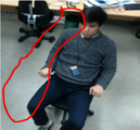
5 is a view showing a background image including a subject.
Fig. 6 is a view showing the depth map of Fig. 5;
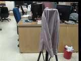
7 is a view showing an image taken by the camera module No. 1 included in the present invention.
8 is a view showing an image taken by the camera module No. 2 included in the present invention.
9 is a view showing an image taken by the camera module No. 3 included in the present invention.
10 is a view showing a first depth map by a pair of camera modules 2 and 3 included in the present invention.
11 is a view showing a second depth map by a pair of camera modules # 2 and # 1 included in the present invention.
12 is a diagram showing a depth map of a final state in which contour lines generated according to the present invention are corrected.
13 is a view of a photographing area of a five-camera module according to an embodiment of the present invention.
FIG. 14 is a view showing only the photographing area of the camera module No. 1 and the camera module No. 2 in FIG.
FIG. 15 is a view showing only the photographing area of the camera module No. 1 and the camera module No. 3 in FIG.
본 발명의 이점 및 특징, 그리고 그것들을 달성하는 기술 등은 첨부되는 도면들과 함께 상세하게 후술되어 있는 실시 예를 참조하면 명확해질 것이다. 그러나 본 발명은 이하에서 개시되는 실시 예에 한정되는 것이 아니라 서로 다른 다양한 형태로 구현될 수 있다. 본 실시 예는 본 발명의 개시가 완전하도록 함과 더불어, 본 발명이 속하는 기술분야에서 통상의 지식을 가진 자에게 발명의 범주를 완전하게 알려주기 위해 제공될 수 있다. The advantages and features of the present invention and the techniques for achieving them will be apparent from the following detailed description taken in conjunction with the accompanying drawings. The present invention may, however, be embodied in many different forms and should not be construed as limited to the embodiments set forth herein. The present embodiments are provided so that the disclosure of the present invention is not only limited thereto, but also may enable others skilled in the art to fully understand the scope of the invention.
본 명세서에서 사용된 용어들은 실시 예를 설명하기 위한 것이며 본 발명을 제한하고자 하는 것은 아니다. 본 명세서에서, 단수형은 문구에서 특별히 언급하지 않는 한 다수형도 포함한다. 또한, 본 명세서에서 언급된 구성요소, 단계, 동작은 하나 이상의 다른 구성요소, 단계, 동작의 존재 또는 추가를 배제하지 않는다.The terms used herein are intended to illustrate the embodiments and are not intended to limit the invention. In this specification, the singular forms include plural forms unless otherwise specified in the text. Furthermore, the components, steps, and operations referred to herein do not preclude the presence or addition of one or more other components, steps, or operations.
한편, 도면의 구성요소는 반드시 축척에 따라 그려진 것은 아니고, 예컨대, 본 발명의 이해를 돕기 위해 도면의 일부 구성요소의 크기는 다른 구성요소에 비해 과장될 수 있다. 또한, 각 도면에 걸쳐 표시된 동일 참조 부호는 동일 구성 요소를 지칭하고, 도시의 간략화 및 명료화를 위해, 도면은 일반적 구성 방식을 도시하고 있다, 또한, 본 발명의 설명된 실시 예의 논의를 불필요하게 불명료하도록 하는 것을 피하기 위해 공지된 특징 및 기술의 상세한 설명은 생략될 수 있다.On the other hand, the constituent elements of the drawings are not necessarily drawn to scale, and for example, the sizes of some constituent elements of the drawings may be exaggerated relative to other constituent elements to facilitate understanding of the present invention. In addition, the same reference numerals denote the same elements throughout the drawings, and for simplicity and clarity of illustration, the drawings show a general constructional method, and the discussion of the described embodiments of the present invention is unnecessarily obscure The detailed description of known features and techniques may be omitted.
이하에서는 본 발명을 구현하기 위한 구체적인 실시예에 대하여 도면을 참조하여 상세히 설명하기로 한다.Hereinafter, embodiments of the present invention will be described in detail with reference to the drawings.
도 1은 본 발명에 따른 3안 스테레오 이미지를 이용한 피사체 윤곽선 개선 시스템을 개략적으로 나타낸 블록도이다.1 is a block diagram schematically illustrating a subject contour improvement system using a three-view stereo image according to the present invention.
도 1을 참조하면, 본 발명에 따른 3안 스테레오 이미지를 이용한 피사체 윤곽선 개선 시스템(100)은 크게 세 개의 카메라 모듈(101,102,103)과 깊이지도 생성부(110), 그리고 폐색영역 보정부(120)를 포함한다.Referring to FIG. 1, a subject
상기 세 개의 카메라 모듈(101,102,103)은 3차원 깊이지도를 생성하기 위한 스테레오 이미지를 촬영하는 카메라로서 동일선 상에 기설정된 베이스라인(baseline)에 따라 이격되어 설치된다. 여기서, 중앙에 배치되는 카메라 모듈을 임의상 2 카메라 모듈(102)로 칭하고, 상기 2번 카메라 모듈(102)을 기준으로 그 좌측 편에 설치되는 카메라 모듈은 1번 카메라 모듈(101), 그리고 2번 카메라 모듈(102)의 우측 편에 설치되는 카메라 모듈은 3번 카메라 모듈(103)로 칭하기로 한다. 물론, 이러한 카메라 모듈의 순번은 발명의 이해를 돕기 위해 임의적으로 부여한 것일 뿐이며 순번에 큰 의미가 있는 것은 아님을 밝혀 둔다.The three
상기 1번 내지 3번 카메라 모듈(103)은 각각 개별 렌즈와 이미지 센서가 구비된 디지털 카메라 혹은 아날로그 카메라가 될 수 있으며, 각각의 위치에서 광축이 서로 평행하도록 배치되어 입체 영상이 생성되는 영역을 공유한다. 다시 말해서, 예컨대 1번 카메라 모듈(101)과 2번 카메라 모듈(102)에서 촬영한 영상 중에서 같은 점이 몇 픽셀 떨어져 있는지 즉, 공유 영상에서 각 카메라모듈의 시차를 계산함으로써 촬영 대상과의 깊이 값을 판단하고 이를 통해 3차원의 깊이지도를 생성하게 된다.The first through
깊이지도를 생성하기 위한 일련의 데이터 처리 과정은 깊이지도 생성부(110)에서 이루어지며, 보다 구체적으로 상기 깊이지도 생성부(110)는 2번 카메라 모듈(102)의 영상을 기준으로 2번 카메라 모듈(102)과 3번 카메라 모듈(103)의 영상을 매칭하여 제1 깊이지도를 생성하는 제1 깊이지도 생성부(111)와, 2번 카메라 모듈(102)의 영상을 기준으로 2번 카메라 모듈(102)과 1번 카메라 모듈(101)의 영상을 매칭하여 제2 깊이지도를 생성하는 제2 깊이지도 생성부(112)로 구성된다. 즉, 제1 깊이지도는 2번 카메라 모듈(102)에서 촬영된 영상 중에서 3번 카메라 모듈(103)에서 촬영된 영상과 공유하는 영역의 시차에 따라 깊이 값이 계산되고, 마찬가지로 제2 깊이지도는 2번 카메라 모듈(102)에서 촬영된 영상 중에서 1번 카메라 모듈(101)에서 촬영된 영상과 공유하는 영역의 시차에 따라 깊이 값이 계산된다. The depth
이처럼 본 발명의 3안 스테레오 이미지를 이용한 피사체 윤곽선 개선 시스템(100)은 기존의 스테레오 카메라와 달리 제1 깊이지도 생성부(111)와 제2 깊이지도 생성부(112)를 통해 두 개의 깊이지도를 생성하는데, 각각의 깊이지도 즉 2,3번 카메라 모듈(102,103) 쌍에 의한 제1 깊이지도와 2,1번 카메라 모듈(101) 쌍에 의한 제2 깊이지도는 각각의 깊이지도에서 발생하는 폐색영역(Occlusion)을 보정함에 있어 상호 보완적으로 사용된다.As described above, in the subject
이하에서는 제1 및 제2 깊이지도에서 발생하는 폐색영역과 폐색영역을 보정하는 과정에 대해 자세히 살펴보기로 한다.Hereinafter, the process of correcting the occlusion area and the occlusion area occurring in the first and second depth maps will be described in detail.
카메라의 촬영 방향을 기준으로 후방에 위치하는 백그라운드(background)와 전방에 위치하는 피사체 즉 전경(foreground, 이하에서 '피사체'는 전경과 같은 의미로 사용)을 촬영한다고 가정하였을 때, 2번 카메라 모듈(102)에서는 촬영되나 3번 카메라 모듈(103)에서는 전방에 위치하는 피사체로 인하여 촬영되지 않는 백그라운드 영역이 생기고 이는 제1 깊이지도에서 폐색영역이 된다. 마찬가지로, 2번 카메라 모듈(102)에서는 촬영되나 1번 카메라 모듈(101)에서는 전방의 피사체로 인하여 촬영되지 않는 백그라운드 영역이 생기고 이는 제2 깊이지도에서 폐색영역이 된다.Assuming that a background located in the back and a foreground (foreground, hereinafter referred to as " subject " is used in the same meaning as foreground) based on the photographing direction of the camera, The
도 2는 1번 내지 3번 카메라 모듈(101,102103)의 촬영 모식도이고, 도 3은 제1 깊이지도에서의 폐색영역을 설명하기 위한 도면, 그리고 도 4는 제2 깊이지도에서의 폐색영역을 설명하기 위한 도면이다.FIG. 3 is a view for explaining the occlusion region in the first depth map, and FIG. 4 is a view for explaining the occlusion region in the second depth map. Fig.
도 2 내지 도 4를 참조하면, 3번 카메라 모듈(103)은 2번 카메라 모듈(102)의 우측 편에 설치됨으로써 전방에 위치하는 피사체의 좌측 편 백그라운드 일부가 피사체에 의해 가려지게 되고, 따라서 3번 카메라 모듈(103)과 피사체의 좌측 가장자리를 연결한 가상의 선이 백그라운드와 만나는 지점에서부터 2번 카메라 모듈(102)과 피사체의 좌측 가장자리를 연결한 가상의 선이 백그라운드와 만나는 지점까지의 영역은 3번 카메라 모듈(103)에서 촬영되지 않고 제1 깊이지도 생성 시 폐색영역(A)으로 남게 된다(도 3). 2 through 4, the
마찬가지로, 1번 카메라 모듈(101)은 2번 카메라 모듈(102)의 좌측 편에 설치됨으로써 전방에 위치하는 피사체의 우측 편 백그라운드 일부가 피사체에 의해 가려지게 되고, 따라서 1번 카메라 모듈(101)에서 피사체의 우측 가장자리를 연결한 가상의 선이 백그라운드와 만나는 지점에서부터 2번 카메라 모듈(102)과 피사체의 우측 가장자리를 연결한 가상의 선이 백그라운드와 만나는 지점까지의 영역은 1번 카메라 모듈(101)에서 촬영되지 않고 제2 깊이지도 생성 시 폐색영역(B)으로 남게 된다(도 4).Likewise, the
도 5는 피사체가 포함된 백그라운드 영상을 나타낸 도면이고, 도 6은 도 5의 깊이지도로서 폐색영역을 설명하기 위한 도면이다. 여기서, 도 6은 2,3번 카메라 모듈(102,103) 쌍에 의한 제1 깊이지도이고 촬영 대상과의 깊이 값 즉 거리에 따라 색이 구분된다. FIG. 5 is a view showing a background image including a subject, and FIG. 6 is a view for explaining a closed area as a depth map of FIG. Here, FIG. 6 is a first depth map by pairs of
전술한대로 제1 깊이지도에서는 피사체의 왼쪽 편으로 폐색영역(A)이 발생하므로, 도 5의 빨간색 영역에 대응되는 도 6의 빨간색 영역에서 보듯이 피사체(사람)의 좌측 윤곽선이 우측 윤곽선에 비해 매끈하지 못하고 백그라운드와 색상이 명확히 구분되지 않음을 확인할 수 있다.As described above, since the occlusion area A is generated on the left side of the subject in the first depth map, the left contour of the subject (person) is smooth compared to the right contour, as shown in the red area of Fig. 6 corresponding to the red area of Fig. And the background and color are not clearly distinguished.
상기 폐색영역 보정부(120)는 이러한 폐색영역에 대해 보정을 가하는 기능을 수행한다. 구체적으로, 2,3번 카메라 모듈(102,103) 쌍에 의한 제1 깊이지도에서 발생하는 폐색영역(A)에 대해서는 2,1번 카메라 모듈(101) 쌍에 의한 제2 깊이지도의 정보를 이용하여 보정하고, 반대로 2,1번 카메라 모듈(101) 쌍에 의한 제2 깊이지도에서 발생하는 폐색영역(B)에 대해서는 2,3번 카메라 모듈(102,103) 쌍에 의한 제1 깊이지도의 정보를 이용하여 보정한다.The occluding
도 2를 보면 3번 카메라 모듈(103)에서 촬영되지 않는 폐색영역(A)는 1번 카메라 모듈(101)에서 촬영되므로 2,1번 카메라 모듈(101) 쌍에 의한 제2 깊이지도에서는 피사체의 왼쪽 윤곽선이 백그라운드와 명확하게 구분되고, 따라서 제2 깊이지도에서 제1 깊이지도의 폐색영역(A)에 매칭되는 영역을 제1 깊이지도와 합성하면 제1 깊이지도에서의 폐색영역(A)는 보정된다. Referring to FIG. 2, since the occlusion area A not photographed by the
마찬가지로, 도 2를 보면 1번 카메라 모듈(101)에 의해 촬영되지 않는 폐색영역(B)는 3번 카메라 모듈(103)에서 촬영되므로 2,3번 카메라 모듈(102,103) 쌍에 의한 제1 깊이지도에서는 피사체의 오른쪽 윤곽선이 백그라운드와 명확하게 구분되고, 따라서 제1 깊이지도에서 제2 깊이지도의 폐색영역(B)에 매칭되는 영역을 제2 깊이지도와 합성하면 제2 깊이지도에서의 폐색영역(B)는 보정된다.Likewise, as shown in FIG. 2, since the closed area B not photographed by the camera module No. 1 is photographed by the
도 7 내지 도 9는 각각 1번 카메라 모듈(101), 2번 카메라 모듈(102), 3번 카메라 모듈(103)의 촬영 영상을 나타낸 도면이고, 도 10은 2,3번 카메라 모듈(102,103) 쌍에 의한 제1 깊이지도를 나타낸 도면, 도 11은 2,1번 카메라 모듈(101) 쌍에 의한 제2 깊이지도를 나타낸 도면, 그리고 도 12는 윤곽선이 보정된 최종 상태의 깊이지도를 나타낸 도면이다.FIGS. 7 to 9 are views showing photographed images of the
깊이지도 생성 시 기준이 되는 도 8의 촬영 이미지 즉, 2번 카메라 모듈(102)의 촬영 영상과 비교하면 1번 카메라의 촬영 영상(도 7)에서는 전방에 위치하는 피사체의 우측 백그라운드 일부가 피사체에 가려지고, 3번 카메라의 촬영 영상(도 9)에서는 피사체의 좌측 백그라운드 일부가 피사체에 가려져 있다. 이에 따라 2,3번 카메라 모듈(102,103) 쌍에 의한 제1 깊이지도에서는 전술한 폐색영역(A)에 의해 피사체의 좌측 윤곽선이 백그라운드와 명확하게 구분되지 못하고 있으며(도 10), 2,1번 카메라 모듈(101) 쌍에 의한 제2 깊이지도에서는 전술한 폐색영역(B)에 의해 피사체의 우측 윤곽선이 백그라운드와 명확하게 구분되지 않는다(도 11). 다만, 반대로 제1 깊이지도에서는 피사체의 우측 윤곽선이 백그라운드와 명확하게 구분되고 있으며 제2 깊이지도에서는 피사체의 좌측 윤곽선이 백그라운드와 명확하게 구분되고 있으므로, 상기 폐색영역 보정부(120)에 의해 제1 깊이지도와 제2 깊이지도가 상호 보완되어 각각의 폐색영역이 보정되면 최종 완성되는 깊이지도에서의 피사체는 도 12에 도시된 것처럼 윤곽선 전체가 백그라운드와 명확하게 구분된다.8, which is a reference for generating the depth map, that is, the captured image of the
지금까지 세 개의 카메라 모듈을 예시로 설명하였으나, 본 발명은 세 개 이상의 카메라 모듈에서도 상기와 같은 방식으로 폐색영역을 보정할 수 있다.Although three camera modules have been described by way of example, the present invention can correct the occlusion area in three or more camera modules in the same manner as described above.
예컨대, 도 13은 다섯 개로 구성된 카메라 모듈의 촬영 모식도로서, 이 경우 촬영 영역이 중복되는 카메라의 조합에 따라 복수의 깊이지도를 생성할 수 있다. 즉, 서로 인접한 한 쌍의 카메라 모듈 예컨대, 도 14에 도시된 것처럼 1,2번 카메라 모듈 쌍에 의한 깊이지도 뿐만 아니라 도 15에 도시된 것처럼 1번 카메라 모듈의 촬영 영역과 3번 카메라 모듈의 촬영 영역이 중복되므로 1,3번 카메라 모듈 쌍에 의한 깊이지도도 생성될 수 있으며, 이와 같이 카메라 모듈의 조합에 의한 복수의 깊이지도에서 발생한 폐색영역에 대해서는 해당 폐색영역이 발생하지 않은 다른 깊이지도의 정보를 이용하여 보정하게 된다.For example, FIG. 13 is a photographing schematic diagram of a camera module composed of five cameras. In this case, a plurality of depth maps can be generated according to a combination of cameras with overlapping shooting regions. That is, not only a depth map of a pair of camera modules adjacent to each other, for example, a pair of
이때, 스테레오 이미지 즉, 깊이지도를 생성하는데 사용되는 두 카메라 모듈의 거리(baseline)에 따라 측정할 수 있는 최소거리가 달라지고, 이하의 수학식 1에 따라 거리 정확도가 달라지기 때문에 촬영 대상이 되는 피사체와의 거리에 따라 가까운 피사체에 대해서는 짧은 베이스라인의 카메라 모듈 쌍(예컨대, 도 14의 1,2번 카메라 모듈 쌍)을 사용하고, 먼 거리의 피사체에 대해서는 긴 베이스라인의 의 카메라 모듈 쌍(예컨대, 도 15의 1,3번 카메라 모듈 쌍)을 사용하는 것이 바람직하다.At this time, since the minimum distance that can be measured depends on the distance of the two camera modules used to generate the stereo image, that is, the depth map, and the distance accuracy is changed according to the following expression (1) (For example, a pair of

(여기서, Disparity는 동일 지점에 대한 두 카메라 모듈의 시차 값, Focallength는 카메라모듈에 포함된 렌즈와 이미지센서 간의 거리, Pixelsize는 카메라 모듈에 사용되는 이미지센서의 픽셀 크기)(Where, Disparity is the parallax value of the two camera modules at the same point, Focallength is the distance between the lens and the image sensor included in the camera module, and Pixelsize is the pixel size of the image sensor used in the camera module)
이상의 상세한 설명은 본 발명을 예시하는 것이다. 또한, 전술한 내용은 본 발명의 바람직한 실시 형태를 나타내고 설명하는 것에 불과하며, 본 발명은 다양한 다른 조합, 변경 및 환경에서 사용할 수 있다. 즉, 본 명세서에 개시된 발명의 개념의 범위, 저술한 개시 내용과 균등한 범위 및/또는 당업계의 기술 또는 지식의 범위 내에서 변경 또는 수정이 가능하다. 전술한 실시 예들은 본 발명을 실시하는데 있어 최선의 상태를 설명하기 위한 것이며, 본 발명과 같은 다른 발명을 이용하는데 당업계에 알려진 다른 상태로의 실시, 그리고 발명의 구체적인 적용 분야 및 용도에서 요구되는 다양한 변경도 가능하다. 따라서, 이상의 발명의 상세한 설명은 개시된 실시 상태로 본 발명을 제한하려는 의도가 아니다. 또한, 첨부된 청구범위는 다른 실시 상태도 포함하는 것으로 해석되어야 한다.The foregoing detailed description is illustrative of the present invention. In addition, the foregoing is merely illustrative and illustrative of preferred embodiments of the invention, and the invention may be used in various other combinations, modifications and environments. That is, it is possible to make changes or modifications within the scope of the concept of the invention disclosed in this specification, the disclosure and the equivalents of the disclosure and / or the scope of the art or knowledge of the present invention. The foregoing embodiments are intended to illustrate the best mode contemplated for carrying out the invention and are not intended to limit the scope of the present invention to other modes of operation known in the art for utilizing other inventions such as the present invention, Various changes are possible. Accordingly, the foregoing description of the invention is not intended to limit the invention to the precise embodiments disclosed. In addition, the appended claims should be construed to include other embodiments.
100: 3안 스테레오 이미지를 이용한 피사체 윤곽선 개선 시스템
101: 1번 카메라 모듈 102: 1번 카메라 모듈
103: 3번 카메라 모듈 110: 깊이지도 생성부
111: 제1 깊이지도 생성부 112: 제2 깊이지도 생성부
120: 폐색영역 보정부100: 3-Stereo Image Contour Enhancement System
101: camera module No. 1 102: camera module No. 1
103: camera module 3, 110: depth map generator
111: first depth map generating unit 112: second depth map generating unit
120: closed area correction unit
Claims (1)
상기 2번 카메라 모듈이 단독 촬영한 영상을 기준으로 상기 2번 카메라 모듈과 상기 3번 카메라 모듈이 동시 촬영한 영상을 매칭하여 제1 깊이지도를 생성하는 제1 깊이지도 생성부와, 상기 2번 카메라 모듈이 단독 촬영한 영상을 기준으로 상기 2번 카메라 모듈과 상기 1번 카메라 모듈이 동시 촬영한 영상을 매칭하여 제2 깊이지도를 생성하는 제2 깊이지도 생성부로 구성된 깊이지도 생성부; 및
상기 제1 깊이지도에서 상기 3번 카메라 모듈에 의해 피사체의 좌측 윤곽선 쪽으로 폐색영역이 생기는 경우 상기 제2 깊이지도의 정보를 이용하여 보정하고, 상기 제2 깊이지도에서 상기 1번 카메라 모듈에 의해 피사체의 우측 윤곽선 쪽으로 폐색영역이 생기는 경우 상기 제1 깊이지도의 정보를 이용하여 보정하는 폐색영역 보정부;를 포함하되,
상기 깊이지도생성부는 상기 1번과 2번 카메라 모듈쌍, 상기 2번과 3번 카메라 모듈쌍이 각각 깊이지도를 생성하는데 있어서 측정할 수 있는 최소거리는 하기의 수학식 1 에 의하여 계산하는 것을 특징으로 하는 3안 스테레오 이미지를 이용한 피사체 윤곽선 개선 시스템.
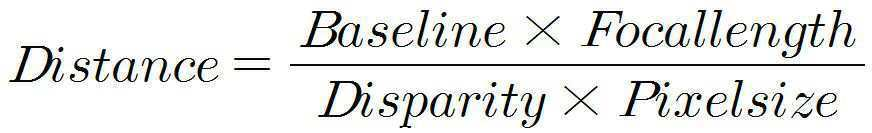
Baseline은 두 카메라 모듈의 거리
Disparity는 동일 지점에 대한 두 카메라 모듈의 시차 값,
Focallength는 카메라모듈에 포함된 렌즈와 이미지센서 간의 거리,
Pixelsize는 카메라 모듈에 사용되는 이미지센서의 픽셀 크기.
A first camera module installed on the left side of the second camera module and a third camera module installed on the right side of the second camera module based on the second camera module installed side by side on the same line Wherein the first to third camera modules are arranged such that the optical axes thereof are parallel to each other at respective positions to calculate a parallax of each of the camera modules to determine a depth value of the camera module;
A first depth map generating unit for generating a first depth map by matching the images captured by the camera module 2 and the camera module 3 simultaneously based on the image captured by the camera module 2, A depth map generation unit configured to generate a second depth map by matching an image captured by the camera module # 2 and the camera module # 1 simultaneously on the basis of an image shot by the camera module; And
Correcting the first depth map by using the information of the second depth map when the third camera module generates a blocked area toward the left contour of the subject by using the camera module No. 3, And an occlusion region correcting unit for correcting the occlusion region using the information of the first depth map when the occlusion region occurs on the right contour of the first depth map,
The depth map generator calculates a minimum distance that can be measured when the pair of camera modules 1 and 2 and the pair of camera modules 2 and 3 respectively generate depth maps by the following Equation 1: Object Contour Enhancement System Using Three - Eye Stereo Images.
Baseline is the distance between two camera modules
Disparity is the time difference of two camera modules for the same point,
Focallength is the distance between the lens included in the camera module and the image sensor,
Pixelsize is the pixel size of the image sensor used in the camera module.
Priority Applications (1)
| Application Number | Priority Date | Filing Date | Title |
|---|---|---|---|
| KR1020150157834A KR101673000B1 (en) | 2015-11-11 | 2015-11-11 | System for improvement of subject outline using 3-lens stereo image |
Applications Claiming Priority (1)
| Application Number | Priority Date | Filing Date | Title |
|---|---|---|---|
| KR1020150157834A KR101673000B1 (en) | 2015-11-11 | 2015-11-11 | System for improvement of subject outline using 3-lens stereo image |
Publications (1)
| Publication Number | Publication Date |
|---|---|
| KR101673000B1 true KR101673000B1 (en) | 2016-11-07 |
Family
ID=57529841
Family Applications (1)
| Application Number | Title | Priority Date | Filing Date |
|---|---|---|---|
| KR1020150157834A Active KR101673000B1 (en) | 2015-11-11 | 2015-11-11 | System for improvement of subject outline using 3-lens stereo image |
Country Status (1)
| Country | Link |
|---|---|
| KR (1) | KR101673000B1 (en) |
Cited By (1)
| Publication number | Priority date | Publication date | Assignee | Title |
|---|---|---|---|---|
| CN112804515A (en) * | 2019-11-14 | 2021-05-14 | 南京深视光点科技有限公司 | Omnidirectional stereoscopic vision camera configuration system and camera configuration method |
Citations (2)
| Publication number | Priority date | Publication date | Assignee | Title |
|---|---|---|---|---|
| KR20140061089A (en) | 2012-11-13 | 2014-05-21 | 재단법인대구경북과학기술원 | Stereo camera control device and method thereof |
| KR20150029897A (en) * | 2013-09-11 | 2015-03-19 | 엘지전자 주식회사 | Photographing device and operating method thereof |
-
2015
- 2015-11-11 KR KR1020150157834A patent/KR101673000B1/en active Active
Patent Citations (2)
| Publication number | Priority date | Publication date | Assignee | Title |
|---|---|---|---|---|
| KR20140061089A (en) | 2012-11-13 | 2014-05-21 | 재단법인대구경북과학기술원 | Stereo camera control device and method thereof |
| KR20150029897A (en) * | 2013-09-11 | 2015-03-19 | 엘지전자 주식회사 | Photographing device and operating method thereof |
Cited By (1)
| Publication number | Priority date | Publication date | Assignee | Title |
|---|---|---|---|---|
| CN112804515A (en) * | 2019-11-14 | 2021-05-14 | 南京深视光点科技有限公司 | Omnidirectional stereoscopic vision camera configuration system and camera configuration method |
Similar Documents
| Publication | Publication Date | Title |
|---|---|---|
| JP5432365B2 (en) | Stereo imaging device and stereo imaging method | |
| CN102957937B (en) | System and method for processing three-dimensional stereo images | |
| JP5444452B2 (en) | Stereo imaging device and stereo imaging method | |
| JP5491617B2 (en) | Stereo imaging device and stereo imaging method | |
| US9253470B2 (en) | 3D camera | |
| KR20120053536A (en) | Image display device and image display method | |
| KR20120030005A (en) | Image processing device and method, and stereoscopic image display device | |
| JP4432462B2 (en) | Imaging apparatus and method, imaging system | |
| CN105230013A (en) | There is multiview three-dimensional display system and the method for the view of location sensing and adaptive quantity | |
| JP5929037B2 (en) | Imaging device | |
| KR102147133B1 (en) | Stereo Camera | |
| JP2011141381A (en) | Stereoscopic image display device and stereoscopic image display method | |
| WO2011070774A1 (en) | 3-d video processing device and 3-d video processing method | |
| JP2009048033A (en) | Stereo imaging device | |
| EP2804379A1 (en) | System and method for providing 3-dimensional images | |
| US20130286164A1 (en) | Glassless 3d image display apparatus and method thereof | |
| KR101673000B1 (en) | System for improvement of subject outline using 3-lens stereo image | |
| KR101994472B1 (en) | Method, apparatus and recording medium for generating mask and both-eye images for three-dimensional image | |
| JP2018205008A (en) | Camera calibration apparatus and camera calibration method | |
| US20160065941A1 (en) | Three-dimensional image capturing apparatus and storage medium storing three-dimensional image capturing program | |
| KR20160042694A (en) | Alignment device for stereoscopic camera and method thereof | |
| JP5689693B2 (en) | Drawing processor | |
| JP2007288229A (en) | Image shooting device | |
| JP5981460B2 (en) | Device and method for managing the position of a focal plane in a stereoscopic scene | |
| KR101680882B1 (en) | Camera arrangement for recording super multi-view image array |
Legal Events
| Date | Code | Title | Description |
|---|---|---|---|
| A201 | Request for examination | ||
| PA0109 | Patent application |
St.27 status event code: A-0-1-A10-A12-nap-PA0109 |
|
| PA0201 | Request for examination |
St.27 status event code: A-1-2-D10-D11-exm-PA0201 |
|
| PA0302 | Request for accelerated examination |
St.27 status event code: A-1-2-D10-D17-exm-PA0302 St.27 status event code: A-1-2-D10-D16-exm-PA0302 |
|
| PE0902 | Notice of grounds for rejection |
St.27 status event code: A-1-2-D10-D21-exm-PE0902 |
|
| T11-X000 | Administrative time limit extension requested |
St.27 status event code: U-3-3-T10-T11-oth-X000 |
|
| T11-X000 | Administrative time limit extension requested |
St.27 status event code: U-3-3-T10-T11-oth-X000 |
|
| P11-X000 | Amendment of application requested |
St.27 status event code: A-2-2-P10-P11-nap-X000 |
|
| P13-X000 | Application amended |
St.27 status event code: A-2-2-P10-P13-nap-X000 |
|
| PE0902 | Notice of grounds for rejection |
St.27 status event code: A-1-2-D10-D21-exm-PE0902 |
|
| P22-X000 | Classification modified |
St.27 status event code: A-2-2-P10-P22-nap-X000 |
|
| P11-X000 | Amendment of application requested |
St.27 status event code: A-2-2-P10-P11-nap-X000 |
|
| P13-X000 | Application amended |
St.27 status event code: A-2-2-P10-P13-nap-X000 |
|
| PE0701 | Decision of registration |
St.27 status event code: A-1-2-D10-D22-exm-PE0701 |
|
| PR0701 | Registration of establishment |
St.27 status event code: A-2-4-F10-F11-exm-PR0701 |
|
| PR1002 | Payment of registration fee |
St.27 status event code: A-2-2-U10-U11-oth-PR1002 Fee payment year number: 1 |
|
| PG1601 | Publication of registration |
St.27 status event code: A-4-4-Q10-Q13-nap-PG1601 |
|
| P22-X000 | Classification modified |
St.27 status event code: A-4-4-P10-P22-nap-X000 |
|
| P22-X000 | Classification modified |
St.27 status event code: A-4-4-P10-P22-nap-X000 |
|
| P22-X000 | Classification modified |
St.27 status event code: A-4-4-P10-P22-nap-X000 |
|
| FPAY | Annual fee payment |
Payment date: 20191014 Year of fee payment: 4 |
|
| PR1001 | Payment of annual fee |
St.27 status event code: A-4-4-U10-U11-oth-PR1001 Fee payment year number: 4 |
|
| PR1001 | Payment of annual fee |
St.27 status event code: A-4-4-U10-U11-oth-PR1001 Fee payment year number: 5 |
|
| P22-X000 | Classification modified |
St.27 status event code: A-4-4-P10-P22-nap-X000 |
|
| PR1001 | Payment of annual fee |
St.27 status event code: A-4-4-U10-U11-oth-PR1001 Fee payment year number: 6 |
|
| PR1001 | Payment of annual fee |
St.27 status event code: A-4-4-U10-U11-oth-PR1001 Fee payment year number: 7 |
|
| P22-X000 | Classification modified |
St.27 status event code: A-4-4-P10-P22-nap-X000 |
|
| P22-X000 | Classification modified |
St.27 status event code: A-4-4-P10-P22-nap-X000 |
|
| PR1001 | Payment of annual fee |
St.27 status event code: A-4-4-U10-U11-oth-PR1001 Fee payment year number: 8 |
|
| PR1001 | Payment of annual fee |
St.27 status event code: A-4-4-U10-U11-oth-PR1001 Fee payment year number: 9 |
|
| P22-X000 | Classification modified |
St.27 status event code: A-4-4-P10-P22-nap-X000 |
|
| PN2301 | Change of applicant |
St.27 status event code: A-5-5-R10-R13-asn-PN2301 St.27 status event code: A-5-5-R10-R11-asn-PN2301 |
|
| PR1001 | Payment of annual fee |
St.27 status event code: A-4-4-U10-U11-oth-PR1001 Fee payment year number: 10 |
|
| U11 | Full renewal or maintenance fee paid |
Free format text: ST27 STATUS EVENT CODE: A-4-4-U10-U11-OTH-PR1001 (AS PROVIDED BY THE NATIONAL OFFICE) Year of fee payment: 10 |