KR101636891B1 - Micro power generator and power generation method using liquid droplet - Google Patents
Micro power generator and power generation method using liquid droplet Download PDFInfo
- Publication number
- KR101636891B1 KR101636891B1 KR1020130049090A KR20130049090A KR101636891B1 KR 101636891 B1 KR101636891 B1 KR 101636891B1 KR 1020130049090 A KR1020130049090 A KR 1020130049090A KR 20130049090 A KR20130049090 A KR 20130049090A KR 101636891 B1 KR101636891 B1 KR 101636891B1
- Authority
- KR
- South Korea
- Prior art keywords
- electrode plate
- liquid droplet
- contact
- casing
- delete delete
- Prior art date
- Legal status (The legal status is an assumption and is not a legal conclusion. Google has not performed a legal analysis and makes no representation as to the accuracy of the status listed.)
- Expired - Fee Related
Links
Images


Classifications
-
- H—ELECTRICITY
- H01—ELECTRIC ELEMENTS
- H01G—CAPACITORS; CAPACITORS, RECTIFIERS, DETECTORS, SWITCHING DEVICES, LIGHT-SENSITIVE OR TEMPERATURE-SENSITIVE DEVICES OF THE ELECTROLYTIC TYPE
- H01G5/00—Capacitors in which the capacitance is varied by mechanical means, e.g. by turning a shaft; Processes of their manufacture
- H01G5/04—Capacitors in which the capacitance is varied by mechanical means, e.g. by turning a shaft; Processes of their manufacture using variation of effective area of electrode
-
- H—ELECTRICITY
- H02—GENERATION; CONVERSION OR DISTRIBUTION OF ELECTRIC POWER
- H02N—ELECTRIC MACHINES NOT OTHERWISE PROVIDED FOR
- H02N1/00—Electrostatic generators or motors using a solid moving electrostatic charge carrier
- H02N1/06—Influence generators
- H02N1/08—Influence generators with conductive charge carrier, i.e. capacitor machines
-
- H—ELECTRICITY
- H02—GENERATION; CONVERSION OR DISTRIBUTION OF ELECTRIC POWER
- H02N—ELECTRIC MACHINES NOT OTHERWISE PROVIDED FOR
- H02N11/00—Generators or motors not provided for elsewhere; Alleged perpetua mobilia obtained by electric or magnetic means
Landscapes
- Engineering & Computer Science (AREA)
- Power Engineering (AREA)
- Microelectronics & Electronic Packaging (AREA)
- Physical Or Chemical Processes And Apparatus (AREA)
Abstract
본 발명은 진동에 의한 전극판과 액체방울 사이의 접촉면적 변화에 의해 유도되는 교류전압을 이용하여 전기를 생산하는 액체방울을 이용한 초소형 발전기 및 발전방법으로서, 본 발명에 의한 초소형 발전기의 경우, 서로 인접하여 마주보고 위치하는 제1전극판 및 제2전극판과, 제1전극판 및 제2전극판 사이에 위치하는 이온이 포함되어 있는 액체방울과, 제1전극판 및 제2전극판 중 적어도 하나가 진동됨에 따라 제1전극판 및 제2전극판 각각에 대한 액체방울의 접촉면적이 시간에 따라 변하면서 제1전극판 및 제2전극판 사이에 발생되는 교류전압을 이용하여 전기를 생산하는 발전부를 포함하여 구성되며, 제1전극판 및 제2전극판 중 적어도 어느 하나는 액체방울과 접촉하는 면에 소수성(hydrophobic)과 친수성(hydrophilic) 중 적어도 어느 한 특성이 부가된 것을 특징으로 한다. The present invention relates to a micro-generator and a power generation method using a liquid droplet for generating electricity by using an AC voltage induced by a change in contact area between an electrode plate and a liquid drop due to vibration. In the case of the micro- A first electrode plate and a second electrode plate positioned adjacent to each other, a liquid droplet containing ions positioned between the first electrode plate and the second electrode plate, and at least one of the first electrode plate and the second electrode plate As one vibrates, the contact area of the liquid droplets with respect to each of the first electrode plate and the second electrode plate changes with time, and electricity is generated using the alternating voltage generated between the first electrode plate and the second electrode plate Wherein at least one of the first electrode plate and the second electrode plate has at least one of a hydrophobic property and a hydrophilic property added to a surface in contact with the liquid droplet, The features.
Description
본 발명은 초소형 발전기에 관한 것으로, 특히 액체방울을 진동시켜 전기를 생산하는 액체방울을 이용한 초소형 발전기 및 발전방법에 관한 것이다.
BACKGROUND OF THE INVENTION 1. Field of the Invention The present invention relates to a micro-generator, and more particularly, to a micro-generator and a power generation method using liquid droplets that generate electricity by vibrating liquid droplets.
각종 휴대용 전자기기로부터 각종 센서 등의 전력원으로 많이 사용되는 전지 방식은 보관이 까다롭게 자체 수명에 대한 한계를 갖고 있다. 일예로, 타이어 공기압 감지 시스템(Tire Pressure Monitoring System : TPMS)에서 이용되는 지능형 무선 압력센서에서부터 가스 감지 센서등 각종 센서 등에 많이 사용되는 리튬전지의 경우 전자자체의 제한된 수명과 함께 보관이 까다로운데, 동작 온도가 올라가면 자연방전이 증가하여 수명이 더욱 줄어든다. BACKGROUND ART [0002] A battery system widely used as a power source for various sensors from various portable electronic devices has a strict limit on its life span. For example, lithium batteries, which are widely used in intelligent wireless pressure sensors used in tire pressure monitoring systems (TPMS), gas sensors, etc., As the temperature rises, the natural discharge increases, further reducing the life span.
한편, 전지 방식에서 벗어난 대체 에너지원으로 한국공개특허 2013-0017343, 한국공개특허 2013-0005445, 한국공개특허 2009-0006250, 한국공개특허 2007-0014328, 한국공개특허 2011-0110444, 일본공개특허 2012-234925, 일본공개특허 2012-175890 등에 개시된 것처럼 최근 압전(Piezoelectric) 현상을 널리 이용하고 있다. 압전 현상은 석영, 전기석과 같은 결정에 일정한 방향에서 압력을 가할 때 그 외력에 비례해서 양전하 또는 음전하가 나타나는 현상이다. 또한 전압을 가할 때 변형이 일어나는 역현상도 있다. 이러한 압전 현상 혹은 역현상은 기계적 변형과 전기적 에너지의 변환에 관한 것이기 때문에 이것을 응용한 마이크나 축음기에 응용되었다. 이러한 압전 현상의 응용 분야는 상기 내용에 국한되지 않고 전자기기에 많이 사용되는 수정 진동자로부터, 최근에는 필름 체적파 공진기(Film Bulk Acoustic Resonator : FBAR)나 표면 탄성파 공진기(Surface Acoustic Wave : SAW)를 이용하여 무선통신용 고성능 필터에까지 응용되어 지고 있다. 게다가 최근 친환경적인 에너지에 대한 관심과 함께, 압전 후막을 이용한 자가 발전기 등이 선을 보였다.On the other hand, as an alternative energy source deviating from the battery system, Korean Patent Publication Nos. 2013-0017343, 2013-0005445, 2009-0006250, Korean Patent Publication 2007-0014328, Korean Patent Publication 2011-0110444, 234925, Japanese Laid-Open Patent Publication No. 2012-175890, and the like. Recently, piezoelectric phenomenon is widely used. Piezoelectric phenomenon is a phenomenon in which a positive or negative charge appears in proportion to an external force when a pressure is applied to a crystal such as quartz or tourmaline in a certain direction. There is also a reverse phenomenon where deformation occurs when a voltage is applied. These piezoelectric phenomena or reverse phenomena are related to the mechanical deformation and the conversion of electrical energy, so they have been applied to microphones and phonographs. The application of such a piezoelectric phenomenon is not limited to the above-mentioned contents. For example, a film bulk acoustic resonator (FBAR) or a surface acoustic wave (SAW) And is applied to high-performance filters for wireless communication. In addition, with the recent interest in environmentally friendly energy, a self-generator using a piezoelectric thick film was shown.
이와 같이 최근 전지 방식에서 벗어난 대체 에너지원의 연구가 계속적으로 진행되는 추세에 있으며, 각종 휴대용 전자기기가 활성화됨에 따라 그에 적합한 새로운 방식의 초소형 발전기를 개발할 필요성은 더욱 더 커지고 있다고 할 수 있다. 하지만 앞서 설명된 것처럼 압전 현상을 이용하는 방식을 제외하면 휴대용 전자기기 등에 사용할 수 있도록 실용화와 발전 효율 측면에서 높은 잠재력을 가진 발전 방식이 거의 없다는 문제점이 있었다.
As such, research on alternative energy sources deviating from the recent battery type is ongoing, and as various portable electronic devices are activated, there is a growing need to develop a new type of miniature generator suitable for the portable electronic devices. However, as described above, there is a problem that there is almost no power generation method having high potential in terms of practical use and power generation efficiency for use in portable electronic devices, except for a method using piezoelectric phenomenon.
본 발명은 상기와 같이 요구되는 에너지원을 해결하기 위해 안출한 것으로서, 진동에 의한 전극판과 액체방울 사이의 접촉면적 변화에 의해 유도되는 교류 전원을 이용하여 전기를 생산하는 액체방울을 이용한 초소형 발전기 및 발전방법을 제공하는데 그 목적이 있다.
The present invention has been made in order to solve the above-mentioned energy source, and it is an object of the present invention to provide a micro generator using liquid droplets for generating electricity using an AC power source induced by a change in contact area between an electrode plate and a liquid drop due to vibration And a method of generating electricity.
상기와 같은 목적을 달성하기 위하여 본 발명의 기술적 사상에 의한 액체방울을 이용한 초소형 발전기는, 서로 인접하여 마주보고 위치하는 제1전극판 및 제2전극판과, 상기 제1전극판 및 제2전극판 사이에 위치하는 이온이 포함되어 있는 액체방울과, 상기 제1전극판 및 제2전극판 중 적어도 하나가 진동됨에 따라 상기 제1전극판 및 제2전극판 각각에 대한 액체방울의 접촉면적이 시간에 따라 변하면서 상기 제1전극판 및 제2전극판 사이에 발생되는 교류전압을 이용하여 전기를 생산하는 발전부를 포함하여 구성되며, 상기 제1전극판 및 제2전극판 중 적어도 어느 하나는 액체방울과 접촉하는 면에 소수성(hydrophobic) 특성이 부가된 것을 그 기술적 구성상의 특징으로 한다. According to an aspect of the present invention, there is provided a micro-generator using a droplet according to the present invention, including a first electrode plate and a second electrode plate facing each other, A liquid droplet containing ions positioned between the first electrode plate and the second electrode plate and a contact area of the liquid droplet with respect to each of the first electrode plate and the second electrode plate as the first electrode plate and the second electrode plate oscillate And at least one of the first electrode plate and the second electrode plate includes a first electrode plate and a second electrode plate, the first electrode plate and the second electrode plate being electrically connected to the first electrode plate and the second electrode plate, The hydrophobic property is added to the surface which is in contact with the liquid droplet.
여기서, 상기 제1전극판 및 제2전극판 중 적어도 어느 하나는 액체방울과 접촉하는 면이 소수성 물질로 코팅된 것을 특징으로 할 수 있다.Here, at least one of the first electrode plate and the second electrode plate may be coated with a hydrophobic material on a surface contacting the liquid droplet.
또한, 상기 제1전극판 및 제2전극판 중 적어도 어느 하나는 액체방울과 접촉하는 면이 소수성을 갖는 형상으로 형성된 것을 특징으로 할 수 있다.At least one of the first electrode plate and the second electrode plate may be formed in a shape having a hydrophobic surface in contact with the liquid droplet.
또한, 상기 제1전극판 및 제2전극판 중 적어도 어느 하나는 액체방울과 접촉하는 면에 요철부가 형성되어 상기 액체방울과 접촉 가능한 표면적을 넓힐 수 있도록 한 것을 특징으로 할 수 있다.At least one of the first electrode plate and the second electrode plate may have a concavo-convex portion on a surface contacting the liquid droplet so that a surface area capable of contacting the liquid droplet can be widened.
또한, 상기 제1전극판 및 제2전극판 중 적어도 어느 하나는 액체방울과 접촉하는 면에 다수의 미세돌기가 형성되어 상기 액체방울과 접촉 가능한 표면적을 넓힐 수 있도록 한 것을 것을 특징으로 할 수 있다.At least one of the first electrode plate and the second electrode plate may have a plurality of fine protrusions formed on a surface of the first electrode plate and the second electrode plate which are in contact with the liquid droplet so that the surface area capable of contacting the liquid droplet can be widened .
또한, 상기 제1전극판 및 제2전극판 중 적어도 어느 하나는 액체방울과 접촉하는 면에 다수의 미세홈이 형성되어 상기 액체방울과 접촉 가능한 표면적을 넓힐 수 있도록 한 것을 특징으로 할 수 있다.At least one of the first electrode plate and the second electrode plate may have a plurality of fine grooves formed on a surface thereof in contact with the liquid droplet so that the surface area capable of contacting the liquid droplet can be widened.
또한, 상기 제1전극판 및 제2전극판 중 적어도 어느 하나는 액체방울과 접촉하는 면이 소수성의 소재로 이루어진 것을 특징으로 할 수 있다.At least one of the first electrode plate and the second electrode plate may be made of a material having a hydrophobic surface in contact with the liquid droplet.
또한, 상기 제1전극판 및 제2전극판 중 어느 하나의 액체방울이 접촉하는 면에는 소수성 특성이 부가되고, 나머지 하나의 액체방울이 접촉하는 면에는 친수성 특성이 부가되는 것을 특징으로 할 수 있다.In addition, a hydrophobic property may be added to a surface of the first electrode plate and / or a second electrode plate that is in contact with the liquid droplet, and a hydrophilic property may be added to a surface of the other electrode.
또한, 상기 제1전극판의 액체방울이 접촉하는 면에는 소수성 특성이 부가되고, 상기 제2전극판의 액체방울이 접촉하는 면에는 친수성 특성이 부가되되, 상기 제1전극판은 제2전극판에 대하여 상측에 위치하는 것을 특징으로 할 수 있다.A hydrophobic property is added to the surface of the first electrode plate which is in contact with the liquid droplet, and a hydrophilic property is added to a surface of the second electrode plate on which the liquid droplet contacts, And is located on the upper side.
또한, 상기 제2전극판의 액체방울이 접촉하는 면에는 액체방울이 위치할 수 있도록 포지션 통공을 구비한 다공 레이어가 더 형성되고, 상기 레이어는 소수성 물질로 이루어진 것을 특징으로 할 수 있다.In addition, a porous layer having a position hole may be formed on a surface of the second electrode plate on which the liquid droplet contacts, and the layer may be formed of a hydrophobic material.
또한, 상기 제2전극판의 액체방울이 접촉하는 면에는 상기 다공 레이어의 포지션 통공과 대응하여 액체방울이 위치하도록 포지션 홈이 더 형성되는 것을 특징으로 할 수 있다.In addition, a position groove may be formed on a surface of the second electrode plate on which the liquid droplet makes contact so that the liquid droplet is positioned corresponding to the position hole of the porous layer.
또한, 상기 액체방울이 위치하는 제1전극판과 제2전극판 사이의 영역은 밀봉되어 있는 것을 특징으로 할 수 있다.The area between the first electrode plate and the second electrode plate where the liquid droplet is located may be sealed.
또한, 상기 제1전극판과 제2전극판 사이의 밀봉된 영역은 액체방울의 증발을 적어도 부분적으로 억제하도록 수분이 포함된 것을 특징으로 할 수 있다.In addition, the sealed region between the first electrode plate and the second electrode plate may be characterized in that water is contained so as to at least partially suppress the evaporation of the droplet.
또한, 상기 제1전극판 및 제2전극판 및 그 사이의 영역을 밀봉되게 감쌀 수 있도록, 상기 제1전극판에 결합되는 제1케이싱과, 상기 제2전극판에 결합되는 제2케이싱과, 상기 제1케이싱과 제2케이싱의 둘레부 사이에 설치되어 상기 제1케이싱과 제2케이싱 사이의 영역을 밀봉하고 상기 제1전극판 및 제2전극판 사이의 거리 변화에 대응할 수 있도록 신축 가능한 소재로 이루어진 실링부재를 구비하는 것을 특징으로 할 수 있다. A first casing coupled to the first electrode plate, a second casing coupled to the second electrode plate, and a second casing coupled to the second electrode plate so as to seal the first and second electrode plates and the area between the first and second electrode plates, And a flexible material which is provided between the first casing and the second casing so as to seal the area between the first casing and the second casing and to correspond to a change in distance between the first and second electrode plates, And a sealing member made of a metal material.
또한, 본 발명은 서로 인접하여 마주보고 위치하는 제1전극판 및 제2전극판과, 상기 제1전극판 및 제2전극판 사이에 위치하는 이온이 포함되어 있는 액체방울과, 상기 제1전극판 및 제2전극판 중 적어도 하나가 진동됨에 따라 상기 제1전극판 및 제2전극판 각각에 대한 액체방울의 접촉면적이 시간에 따라 변하면서 상기 제1전극판 및 제2전극판 사이에 발생되는 교류전압을 이용하여 전기를 생산하는 발전부를 포함하여 구성되며, 상기 제1전극판 및 제2전극판 중 적어도 어느 하나는 액체방울과 접촉하는 면에 표면적을 넓히는 표면처리가 된 것을 그 기술적 구성상의 특징으로 할 수 있다. According to another aspect of the present invention, there is provided a plasma display panel comprising a first electrode plate and a second electrode plate facing each other and facing each other, a liquid droplet containing ions positioned between the first electrode plate and the second electrode plate, As the at least one of the plate and the second electrode plate is vibrated, the contact area of the liquid droplet with respect to each of the first electrode plate and the second electrode plate changes with time and occurs between the first electrode plate and the second electrode plate And at least one of the first electrode plate and the second electrode plate is subjected to a surface treatment for widening the surface area on the side in contact with the liquid droplet, .
한편, 본 발명에 의한 액체방울을 이용한 발전방법은 서로 인접하여 마주보는 제1전극판 및 제2전극판 사이에 이온이 포함된 액체방울을 위치시킨 상태에서, 상기 제1전극판과 제2전극판 중 적어도 하나에 진동을 가하여 상기 제1전극판 및 제2전극판 각각에 대한 액체방울의 접촉면적을 시간에 따라 변화시킴으로써 이때 상기 제1전극판 및 제2전극판 사이에 발생되는 교류전압을 이용하여 전기를 생산하는 것을 그 기술적 구성상의 특징으로 할 수 있으며, 위 언급된 특징들이 부가될 수 있다.
Meanwhile, in a method of generating electricity using a droplet according to the present invention, in a state where a liquid droplet containing ions is positioned between a first electrode plate and a second electrode plate which are adjacent to each other, the first electrode plate and the second electrode At least one of the plates is vibrated to change the contact area of the liquid droplets with respect to the first electrode plate and the second electrode plate with time so that an AC voltage generated between the first electrode plate and the second electrode plate at this time It is a technical feature of the present invention to produce electricity using the above-mentioned characteristics, and the above-mentioned characteristics can be added.
이상에서 설명한 바와 같은 본 발명에 따른 액체방울을 이용한 초소형 발전기 및 발전방법은, 작은 진동수에서도 발전이 가능하여 사용자의 생활 진동을 비롯한 다양한 근원에서 얻을 수 있는 진동을 이용하여 발전함으로써 친환경 발전 시스템으로의 개발에 적용할 수 있다.As described above, the micro-generator and the power generation method using the liquid droplet according to the present invention can generate power even at a small frequency and can generate electricity using vibrations obtained from various sources including the user's life vibrations, It can be applied to development.
또한, 본 발명은 생활 진동을 이용하는 경우 소형 전자기기에 적용하여 자가 발전하는 초소형 발전기로 쉽게 응용할 수 있다. In addition, the present invention can be easily applied to a small-sized generator that is self-generated when applied to small-sized electronic devices when living vibration is used.
또한, 본 발명은 제1전극판 및 제2전극판 중 적어도 어느 하나에 소수성(hydrophobic)과 친수성(hydrophilic) 중 적어도 어느 한 특성을 부가한 구성에 의해 제1전극판과 제2전극판에 각각에 대한 액체방울의 접촉각, 접촉면적 등의 요인들에 변화를 주고 이를 통해 더 높은 발전 효율을 모색할 수 있다. According to the present invention, at least any one of hydrophobic and hydrophilic properties is added to at least one of the first electrode plate and the second electrode plate, The contact angle of the liquid droplet with respect to the contact angle of the liquid droplet, the contact area, and the like, and thereby, a higher power generation efficiency can be sought.
또한, 본 발명은 제1전극판 및 제2전극판 중 적어도 어느 하나에 대하여 액체방울과 접촉하는 면을 표면처리하여 요철부, 미세돌기, 미세홈 등을 형성하는 구성에 의해 액체방울과 접촉 가능한 표면적을 극대화함으로써 발전효과를 높일 수 있다.
In addition, the present invention is characterized in that at least one of the first electrode plate and the second electrode plate is surface-treated with a surface in contact with the liquid droplets to form irregularities, fine projections, fine grooves, By maximizing the surface area, the power generating effect can be enhanced.
도 1은 본 발명의 실시예에 의한 액체방울을 이용한 초소형 발전기의 구조를 나타낸 구성도
도 2 및 도 3은 본 발명의 실시예에 의한 액체방울을 이용한 초소형 발전기에서 발생되는 전기 이중층을 설명하기 위한 참조도
도 4는 본 발명의 실시예에 의한 초소형 발전기에서 발전되는 교류전압을 나타낸 그래프
도 5 는 본 발명의 실시예에 의한 액체방울을 이용한 초소형 발전기가 다수개의 액체방울을 이용한 구조를 나타낸 구성도
도 6은 본 발명의 제1변형실시예에 의한 액체방울을 이용한 초소형 발전기의 구성을 설명하기 위한 부분 구성도
도 7은 본 발명의 제2변형실시예에 의한 액체방울을 이용한 초소형 발전기의 구성을 설명하기 위한 부분 구성도
도 8은 본 발명의 제3변형실시예에 의한 액체방울을 이용한 초소형 발전기의 구성을 설명하기 위한 부분 구성도
도 9는 본 발명의 제4변형실시예에 의한 액체방울을 이용한 초소형 발전기의 구성을 설명하기 위한 부분 구성도
도 10은 본 발명의 제5변형실시예에 의한 액체방울을 이용한 초소형 발전기의 구성을 설명하기 위한 부분 구성도
도 11은 본 발명의 제6변형실시예에 의한 액체방울을 이용한 초소형 발전기의 구성을 설명하기 위한 부분 구성도
도 12는 본 발명의 제6변형실시예에 의한 액체방울을 이용한 초소형 발전기에 진동이 가해질 때의 동작 및 변화를 설명하기 위한 참조동작도
도 13은 본 발명의 제7변형실시예에 의한 액체방울을 이용한 초소형 발전기의 더욱 구체화한 세부 구성도
도 14는 본 발명의 제8변형실시예에 의한 액체방울을 이용한 초소형 발전기의 구성을 설명하기 위한 제2전극판의 단면도
도 15는 본 발명의 제8변형실시예에 따른 제2전극판의 사시도 1 is a block diagram showing a structure of a micro generator using liquid droplets according to an embodiment of the present invention;
2 and 3 are views for explaining an electric double layer generated in a micro-generator using liquid droplets according to an embodiment of the present invention.
4 is a graph showing an AC voltage generated in the micro-generator according to the embodiment of the present invention
5 is a diagram showing a structure of a micro-generator using liquid droplets according to an embodiment of the present invention using a plurality of liquid droplets
6 is a partial structural diagram for explaining a configuration of a micro generator using liquid droplets according to a first modified example of the present invention
7 is a partial structural diagram for explaining a configuration of a micro generator using a liquid droplet according to a second modified embodiment of the present invention
8 is a partial structural diagram for explaining a configuration of a micro generator using a droplet according to a third modified embodiment of the present invention
9 is a partial structural diagram for explaining a configuration of a micro generator using a liquid droplet according to a fourth modified embodiment of the present invention
10 is a partial structural diagram for explaining a configuration of a micro generator using liquid droplets according to a fifth modified embodiment of the present invention
11 is a partial structural diagram for explaining a configuration of a micro generator using liquid droplets according to a sixth modified embodiment of the present invention
12 is a reference operation diagram for explaining an operation and a change when vibration is applied to a micro generator using a liquid drop according to a sixth modified embodiment of the present invention
13 is a more detailed detailed configuration diagram of a micro-generator using a droplet according to a seventh modified embodiment of the present invention
14 is a sectional view of a second electrode plate for explaining the structure of a micro generator using a droplet according to an eighth modified embodiment of the present invention
15 is a perspective view of a second electrode plate according to an eighth modified embodiment of the present invention.
첨부한 도면을 참조하여 본 발명의 실시예들에 의한 액체방울을 이용한 초소형 발전기 및 발전방법에 대하여 초소형 발전기를 중심으로 상세히 설명한다. 본 발명은 다양한 변경을 가할 수 있고 여러 가지 형태를 가질 수 있는바, 특정 실시예들을 도면에 예시하고 본문에 상세하게 설명하고자 한다. 그러나 이는 본 발명을 특정한 개시 형태에 대해 한정하려는 것이 아니며, 본 발명의 사상 및 기술 범위에 포함되는 모든 변경, 균등물 내지 대체물을 포함하는 것으로 이해되어야 한다. 각 도면을 설명하면서 유사한 참조부호를 유사한 구성요소에 대해 사용하였다. 첨부된 도면에 있어서, 구조물들의 치수는 본 발명의 명확성을 기하기 위하여 실제보다 확대하거나, 개략적인 구성을 이해하기 위하여 실제보다 축소하여 도시한 것이다.The micro-generator and the power generation method using the liquid droplet according to the embodiments of the present invention will be described in detail with reference to the attached drawings, focusing on the micro-generator. The present invention is capable of various modifications and various forms, and specific embodiments are illustrated in the drawings and described in detail in the text. It is to be understood, however, that the invention is not intended to be limited to the particular forms disclosed, but on the contrary, is intended to cover all modifications, equivalents, and alternatives falling within the spirit and scope of the invention. Like reference numerals are used for like elements in describing each drawing. In the accompanying drawings, the dimensions of the structures are enlarged to illustrate the present invention, and are actually shown in a smaller scale than the actual dimensions in order to understand the schematic structure.
또한, 제1 및 제2 등의 용어는 다양한 구성요소들을 설명하는데 사용될 수 있지만, 상기 구성요소들은 상기 용어들에 의해 한정되어서는 안 된다. 상기 용어들은 하나의 구성요소를 다른 구성요소로부터 구별하는 목적으로만 사용된다. 예를 들어, 본 발명의 권리 범위를 벗어나지 않으면서 제1 구성요소는 제2 구성요소로 명명될 수 있고, 유사하게 제2 구성요소도 제1 구성요소로 명명될 수 있다. 한편, 다르게 정의되지 않는 한, 기술적이거나 과학적인 용어를 포함해서 여기서 사용되는 모든 용어들은 본 발명이 속하는 기술분야에서 통상의 지식을 가진 자에 의해 일반적으로 이해되는 것과 동일한 의미를 가지고 있다. 일반적으로 사용되는 사전에 정의되어 있는 것과 같은 용어들은 관련 기술의 문맥 상 가지는 의미와 일치하는 의미를 가지는 것으로 해석되어야 하며, 본 출원에서 명백하게 정의하지 않는 한, 이상적이거나 과도하게 형식적인 의미로 해석되지 않는다.
Also, the terms first and second, etc. may be used to describe various components, but the components should not be limited by the terms. The terms are used only for the purpose of distinguishing one component from another. For example, without departing from the scope of the present invention, the first component may be referred to as a second component, and similarly, the second component may also be referred to as a first component. On the other hand, unless otherwise defined, all terms used herein, including technical or scientific terms, have the same meaning as commonly understood by one of ordinary skill in the art to which this invention belongs. Terms such as those defined in commonly used dictionaries are to be interpreted as having a meaning consistent with the contextual meaning of the related art and are to be interpreted as either ideal or overly formal in the sense of the present application Do not.
도 1은 본 발명의 실시예에 의한 액체방울을 이용한 초소형 발전기의 구조를 나타낸 구성도이고, 도 2 및 도 3은 본 발명의 실시예에 의한 액체방울을 이용한 초소형 발전기에서 발생되는 전기 이중층을 설명하기 위한 참조도이다. FIG. 1 is a configuration diagram illustrating a structure of a micro-generator using a liquid droplet according to an embodiment of the present invention, and FIGS. 2 and 3 illustrate an electric double layer generated in a micro-generator using a liquid droplet according to an embodiment of the present invention Fig.
도 1과 같이, 초소형 발전기는 서로 인접하여 마주보고 위치하는 제 1전극판(10) 및 제2전극판(20)과, 상기 제1전극판(10) 및 제2전극판(20) 사이에 위치하는 이온이 포함되어 있는 액체방울(30)과, 진동을 통해 상기 제1전극판(10) 및 제2전극판(20) 사이에 발생되는 교류전압을 이용하여 전기를 생산하는 발전부(40)를 포함하여 구성된다. 상기 액체방울(30)은 순수한 물로 이루어져도 무방하며, 염화나트륨(NaCl)과 같은 이온결합화합물이 용해되어 있는 전해질용액으로 이루어지는 것도 가능하다. 1, the micro-generator includes a
여기서, 상기 제1전극판(10) 및 제2전극판(20) 사이에서 교류전압은 다음과 같은 방식으로 발생된다. 즉, 상기 제1전극판(10) 및 제2전극판(20) 중 적어도 하나가 진동됨에 따라 제1전극판(10) 및 제2전극판(20) 사이의 거리 변화가 야기되고 이로써 제1전극판(10) 및 제2전극판(20)과 액체방울(30)이 접하는 면적이 시간에 따라 변하게 된다. 이때, 상기 제1전극판(10) 및 제2전극판(20)과 액체방울(30)이 접하는 면적의 변화는 전기 이중층에서 전기용량의 변화를 가져온다. 즉, 도 2와 같이, 전극이 용액 중에 침지되면 전극과 용액 사이에는 콘덴서와 같은 +와 -로 대전되는 현상이 일어난다. 이때, 제1전극판(10) 및 제2전극판(20)에 전극이 -로 대전되면 액체방울(30)의 용액 측에서는 +로 대전되며, 제1전극판(10) 및 제2전극판(20)에 전극이 +로 대전되면 액체방울(30)의 용액은 -로 대전된다. 이에 따라 도 3에 도시된 것처럼 전극과 용액 사이에 콘덴서와 같은 전기적 구조인 전기 이중층(electrical double layer)이 나타난다. 일반적으로 조성이 서로 다른 2상의 접촉계면에서, 계면의 한 쪽 측에는 여분의 + 전하가, 다른 측에는 여분의 - 전하가 연속적으로 분포하며, 전체적으로 전기적 중성의 조건을 만족하도록 하는 경계층을 일컫는다. 일반적으로 이종의 물질이 접촉하면, 계면 가까운 전하분포가 변화하거나, 계면을 통하여 하전(荷電)입자의 이동차 때문에 분극이 일어나는데, 이것을 전기 이중층이라고 한다. 이온을 함유한 액체가 고체와 접촉할 때에는 액상 중에 전하의 일부는 계면에 집중되어 고착상(헬므호르쯔층(Helmholz's Layer))을 형성하고, 나머지는 액상 중에 확산적으로 분포하여 확산 이중층을 형성한다고 하는 O. Stern의 이론이 일반적으로 인정받고 있다. 콜로이드 이온의 분위기도 이것과 닮은 구조이다.Here, the AC voltage between the
이에 따라, 상기 제1전극판(10) 및 제2전극판(20)이 진동하면 시간에 따라 면적이 변화해서 전기 이중층 전기용량이 시간에 따라 변화하게 되고, 제1전극판(10)과 제2전극판(20) 사이에 전위차가 시간에 따라 바뀌면서 교류전압이 발생하게 된다. 이때, 상기 제1전극판(10) 및 제2전극판(20)의 진동은 사용자의 직접적인 움직임 또는 핸드폰 등과 같이 사용자의 움직임을 통해 함께 움직임을 갖는 간접적인 움직임은 물론, 자동차, 자전거 등과 같은 이동 수단에 의한 움직임 등과 같은 생활 진동을 이용하여 발생되도록 할 수 있다. 이 외에도 다른 실시예로서, 일정한 주기로 진동을 발생시키는 진동장치(50)를 추가로 구성하고, 구성된 진동장치(50)를 이용하여 진동을 발생시킬 수도 있다.Accordingly, when the
그리고 상기 발전부(40)는 상기 제1전극판(10)과 제2전극판(20) 사이에서 발생되는 교류전압을 이용하여 전기를 생산한다. 이 과정에서 상기 발전부(40)는 저항 값에 따라 생성되는 전압의 크기를 적절한 수준으로 조절하게 된다.The
이때, 상기 제1전극판(10) 및 제2전극판(20)은 진동 중 시간에 따라 액체방울과 접촉면적 변화가 큰 표면성질을 갖는 물질을 코팅하여 전극판과 액체방울(30)이 접하는 면적의 변화를 조절할 수 있다. 즉, 액체방울(30)과 접촉하는 면에 소수성(hydrophobic) 또는 친수성(hydrophilic) 물질(60)을 코팅하여 전극판과 액체방울(30)이 접하는 면적의 변화를 조절할 수 있다. 참고로 소수성 또는 친수성 물질(60)은 상기 제1전극판(10) 및 제2전극판(20)에 동일한 물질(소수성 물질 또는 친수성 물질 중 하나)로 동일하게 코팅될 수도 있고, 서로 상이한 물질 즉, 제1전극판(10)에는 소수성 물질이 코팅되고, 제2전극판(20)에는 친수성 물질이 코팅되거나, 또는 제1전극판(10)에는 친수성 물질이 코팅되고, 제2전극판(20)에는 소수성 물질이 코팅될 수도 있다. 이에 대해서는 차후에 상세히 설명하기로 한다. At this time, the
또한 액체방울(30)은 상기 제1전극판(10) 및 제2전극판(20) 사이에서 밀봉되어 전극판 외부로 누수되지 않아야 한다. 이와 관련된 보다 구체적인 구성에 대해서는 차후에 설명하기로 한다. Also, the
도 4는 40마이크로미터(μl)의 양을 갖는 액체방울(30)을 5Hz로 진동시켰을 때 초소형 발전기에서 발전되는 교류전압을 그래프로 나타낸 것이다. 도 4와 같이, 본 발명의 초소형 발전기는 진동에 의해 제1전극판(10) 및 제2전극판(20)과 액체방울(30) 사이의 면적 변화가 발생되며, 이 면적 변화에 의해 교류전압이 유도되는 것을 확인할 수 있다. Fig. 4 is a graphical representation of the alternating voltage generated in the micro-generator when the
도 5 는 본 발명의 실시예에 의한 액체방울을 이용한 초소형 발전기가 다수개의 액체방울을 이용하는 구조를 나타낸 구성도이다. 5 is a configuration diagram showing a structure in which a micro-generator using liquid droplets according to an embodiment of the present invention uses a plurality of liquid droplets.
도 5에 도시된 것처럼 상기 제1전극판(10) 및 제2전극판(20) 사이의 영역에서 형성되는 액체방울(30)은 다수개의 액체방울(30)로 구성되는 것이 바람직하다. 이처럼 다수개의 액체방울(30)로 구성되는 경우 발전부(40)에서 생성되는 교류전압의 전력량 및 효율을 증가시킬 수 있기 때문이다. As shown in FIG. 5, the
한편, 본 발명은 앞서 잠깐 언급되었듯이 상기 제1전극판(10) 및 제2전극판(20) 중 적어도 어느 하나에 소수성(hydrophobic)과 친수성(hydrophilic) 중 적어도 어느 한 특성이 부가되도록 하여 액체방울(30)이 접촉하는 면적의 변화속도를 조절할 수 있다. 또한 상기 제1전극판(10) 및 제2전극판(20) 중 적어도 어느 하나에 대하여 액체방울(30)이 접촉 가능한 표면적을 극대화하는 구성도 가능하다. 아래에서는 이같은 두 가지 부면에 초점을 맞추어 구성된 다양한 변형실시예에 대해 설명하기로 한다.
In the meantime, the present invention is characterized in that at least one of hydrophobic and hydrophilic properties is added to at least one of the
도 6은 본 발명의 제1변형실시예에 의한 액체방울을 이용한 초소형 발전기의 구성을 설명하기 위한 부분 구성도이다. 6 is a partial structural diagram for explaining a configuration of a micro generator using liquid droplets according to a first modified example of the present invention.
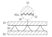
도시된 바와 같이, 본 발명의 제1변형실시예에서는 상측에 위치한 제1전극판(10)이 액체방울(30)과 접촉하는 면에 요철부(11)가 형성된 것을 특징으로 한다. 이같은 제1변형실시예의 구성에 따르면 상측에 위치하기 때문에 제2전극판(20)에 비해 액체방울(30)과의 접촉면적 변화가 더 활발하게 이루어지는 제1전극판(10)이 액체방울(30)과 접촉 가능한 표면적을 더 넓게 확보함에 따라 더 높은 발전 효과를 기대할 수 있다. As shown in the drawings, the first modified embodiment of the present invention is characterized in that the
또한, 상기 제1전극판(10)은 요철부(11)가 형성됨에 따라 표면적의 증가뿐만 아니라 소수성이나 친수성의 특성을 갖는 효과도 기대할 수 있다. 이는 상기 제1전극판(10)의 소재나 상기 요철부(11)의 크기 및 형태에 따라 달라질 수 있지만 상기 요철부(11)의 저부와 산부 크기가 나노미터에 속할 정도로 작아지면 일반적으로 소수성의 특성을 갖게 될 가능성이 높고 반대로 요철부(11)의 저부와 산부 크기가 커지면 친수성 특성을 갖게 될 가능성이 높다.
In addition, the
도 7은 본 발명의 제2변형실시예에 의한 액체방울을 이용한 초소형 발전기의 구성을 설명하기 위한 부분 구성도이다. 7 is a partial structural diagram for explaining a configuration of a micro generator using a liquid droplet according to a second modification of the present invention.
도시된 바와 같이, 본 발명의 제2변형실시예에서는 상측에 위치한 제1전극판(10)이 액체방울(30)과 접촉하는 면에 다수의 미세돌기(12)가 형성된 것을 특징으로 한다. 이같은 제2변형실시예의 구성에 따르면 제1변형실시에와 마찬가지로 하측에 위치하는 제2전극판(20)에 비해 액체방울(30)과의 접촉면적 변화가 더 활발하게 이루어지는 제1전극판(10)이 액체방울(30)과 접촉 가능한 표면적을 더 넓게 확보함에 따라 더 높은 발전 효과를 기대할 수 있다. As shown in the drawing, the second modification of the present invention is characterized in that a plurality of
이 경우에도 상기 미세돌기(12)의 크기 및 촘촘한 정도에 따라 소수성이나 친수성의 특성을 갖는 효과도 기대할 수 있다.
Also in this case, the effect of having a hydrophobic property or a hydrophilic property can be expected depending on the size and the close degree of the
도 8은 본 발명의 제3변형실시예에 의한 액체방울을 이용한 초소형 발전기의 구성을 설명하기 위한 부분 구성도이다. 8 is a partial structural diagram for explaining a configuration of a micro generator using a droplet according to a third modified embodiment of the present invention.
도시된 바와 같이, 본 발명의 제3변형실시예에서는 상측에 위치한 제1전극판(10)이 액체방울(30)과 접촉하는 면에 다수의 미세홈(13)이 형성된 것을 특징으로 한다. 이같은 제3변형실시예의 구성에 따르면 제1변형실시에와 마찬가지로 하측에 위치하는 제2전극판(20)에 비해 액체방울(30)과의 접촉면적 변화가 더 활발하게 이루어지는 제1전극판(10)이 액체방울(30)과 접촉 가능한 표면적을 더 넓게 확보함에 따라 더 높은 발전 효과를 기대할 수 있다. As shown in the figure, in the third modification of the present invention, a plurality of
이 경우에도 상기 미세홈(13)의 크기 및 촘촘한 정도에 따라 소수성이나 친수성의 특성을 갖는 효과도 기대할 수 있다.
Also in this case, the hydrophobic property and the hydrophilic property can be expected depending on the size and the close degree of the
도 9는 본 발명의 제4변형실시예에 의한 액체방울을 이용한 초소형 발전기의 구성을 설명하기 위한 부분 구성도이다. 9 is a partial structural diagram for explaining a configuration of a micro generator using a liquid drop according to a fourth modified embodiment of the present invention.
도시된 바와 같이, 본 발명의 제4변형실시예에서는 상측에 위치한 제1전극판(10)이 액체방울(30)과 접촉하는 면에 요철부(11)가 형성되고, 그 표면에 소수성 코팅 레이어(60a)가 형성되어 소수성 특성이 부가된 것을 특징으로 한다. 예컨대, 제1전극판(10)은 ITO([Indium Tin Oxide) 소재로 구비하여 상기 요철부(11)를 형성하고, 그 표면에 PTFE (Polytetrafluoroethylene)를 소수성 물질로 코팅하여 소수성 코팅 레이어(60a)를 형성할 수 있다. As shown in the drawing, in the fourth modified embodiment of the present invention, the
이같은 제4변형실시예에 따르면 제2전극판(20)에 비해 액체방울(30)과의 접촉면적 변화속도가 높은 제1전극판(10)이 액체방울(30)과 접촉 가능한 표면적을 더 넓게 확보하는 동시에 그 표면에 소수성 특성이 부가됨에 따라 상기 제1전극판(10)과 액체방울(30)과의 접촉면적 변화가 매우 원활하게 이루이지게 되며, 이로써 더 높은 발전효과를 기대할 수 있다. According to the fourth modified embodiment, the surface area at which the
이처럼 상측에 위치하여 진동시 액체방울(30)과의 접촉면적 변화속도가 제2전극판(20)에 비해 높은 제1전극판(10)에 액체방울(30)과 접촉 가능한 표면적을 더 넓게 확보하는 동시에 소수성 특성을 부가함으로써 발전효과를 극대화하고, 진동시 제1전극판(10)에 비해 액체방울(30)과의 접촉면적 변화속도가 상대적으로 낮은 제2전극판(20)의 경우에는 액체방울(30)과 접촉 가능한 표면적은 넓게 확보하면서 친수성 특성을 부가함으로써 액체방울(30)의 포지션을 안정적으로 유지하는 것이 가장 이상적인 형태에 가까운 것으로 여겨진다. 다만, 제1전극판(10) 및 제2전극판(20)에 대한 액체방울(30)의 접촉면적, 접촉각 및 부착력 등의 다양한 요인들이 발전효과에 변수들로 작용하기 때문에 상기와 같이 이상적으로 여겨지는 형태만이 최고의 발전효율을 얻을 수 있다고 단정할 수는 없다.The surface area at which the contact area change rate of the contact with the
한편, 전술된 제1변형실시 내지 제4변형실시예는 액체방울(30)과의 접촉 가능한 표면적을 넓히기 위한 구성과 소수성 또는 친수성 특성을 갖도록 한 구성을 주로 상측에 위치한 제1전극판(10)에만 적용하는 것으로 설명하였으나, 하측에 위치한 제2전극판(20)에도 동일한 방식으로 적용할 수 있다. 이에 대한 일부 사례들을 계속되는 변형실시예를 통하여 살펴보기로 한다. The first to fourth modified examples described above are different from the first to fourth modified examples in that a structure for widening the surface area capable of contacting with the
도 10은 본 발명의 제5변형실시예에 의한 액체방울을 이용한 초소형 발전기의 구성을 설명하기 위한 부분 구성도이다. 10 is a partial structural diagram for explaining a configuration of a micro generator using liquid droplets according to a fifth modified embodiment of the present invention.
도시된 바와 같이, 본 발명의 제5변형실시예는 상측에 위치한 제1전극판(10)과 하측에 위치한 제2전극판(20) 모두에 표면적을 극대화하기 위한 요철부(11)(21)를 동일하게 형성시키되, 제1전극판(10)에는 액체방울(30)과 접촉하는 면에 소수성 특성이 부가되도록 하고, 제2전극판(20)에는 액체방울(30)과 접촉하는 면에 친수성 특성이 부가되도록 하여 차별화한 구성을 특징으로 한다. As shown in the drawing, the fifth modified embodiment of the present invention includes the
여기서, 상기 제1전극판(10)에 소수성 특성을 부가하기 위해 소수성 물질을 코팅하여 이루어진 소수성 코팅 레이어(60a)가 구비되고, 상기 제2전극판(20)에 친수성 특성을 부가하기 위해 친수성 물질로 코팅하여 이루어진 친수성 코팅 레이어(60c)가 구비될 수 있다. 예컨대, 상기 제1전극판(10)에는 PTFE (Polytetrafluoroethylene)가 소수성 물질로 코팅될 수 있고, 제2전극판(20)에는 HEMA(hydroxyethylmethacrylate)가 친수성 물질로 코팅될 수 있다. 단, 상기 요철부(11)(21) 표면에 소수성 및 친수성 특성을 부가하는 방법은 해당 물질을 코팅하는 방법 외에도 다양한 표면개질이나 화학적 처리방법 등 다양하게 있으므로 어느 한 가지 방법에만 제한을 두지 않고 상황에 맞게 적당한 방법을 선택하여 적용할 수 있다. In order to add a hydrophobic property to the
이와 같은 제5변형실시예의 구성에 의하면, 제1전극판(10)과 제2전극판(20) 모두 액체방울(30)이 접촉 가능한 표면적은 극대화한 한편, 진동이 가해지는 동안 제1전극판(10)은 소수성 코팅 레이어(60a)에 의하여 접촉면적의 변화가 원활하게 이루어지도록 하고, 제2전극판(20)은 친수성 코팅 레이어(60c)에 의하여 액체방울(30)이 안정적으로 포지션을 유지할 수 있도록 하여 보다 향상된 발전효과를 기대할 수 있다.
According to the configuration of the fifth modified embodiment, the surface area at which the
도 11은 본 발명의 제6변형실시예에 의한 액체방울을 이용한 초소형 발전기의 구성을 설명하기 위한 부분 구성도이고, 도 12는 본 발명의 제6변형실시예에 의한 액체방울을 이용한 초소형 발전기에 진동이 가해질 때의 동작 및 변화를 설명하기 위한 참조동작도이다. FIG. 11 is a partial structural view for explaining a configuration of a micro-generator using a liquid droplet according to a sixth modified embodiment of the present invention, and FIG. 12 is a cross-sectional view of a micro-generator using a liquid droplet according to a sixth modified embodiment of the present invention And is a reference operation diagram for explaining an operation and a change when vibration is applied.
도시된 바와 같이, 본 발명의 제6변형실시예는 상측에 위치한 제1전극판(10)에 소수성 특성이 부가되고 하측에 위치한 제2전극판(20)에는 더 넓은 표면적을 확보할 수 있도록 구성된 것을 특징으로 한다. As shown in the figure, the sixth modified embodiment of the present invention is characterized in that a hydrophobic property is added to the
이를 위해 상기 제1전극판(10)에서 액체방울(30)과 접촉하는 면에는 소수성 물질로 코팅되어 형성된 소수성 코팅 레이어(60a)가 구비된다. 그리고 하측에 위치하는 제2전극판(20)에는 액체방울(30)과 접촉하는 면에 요철부(21)가 형성된다. 여기서, 상기 요철부(21)는 돌출된 산부의 형태가 피라미드 형태인 것으로 도시되었지만, 삼각뿔, 반구 형태와 같이 다양한 형태로도 가능하다. To this end, a
이와 같은 제6변형실시예는 제1변형실시예 내지 제5변형실시예와 마찬가지로 제1전극판(10) 및 제2전극판(20)에 대하여 소수성 및 친수성의 적용과, 표면적을 극대화한 구성의 한 형태를 예시한 것으로, 상측에 위치한 제1전극판(10)에는 표면적의 극대화는 없지만 소수성 특성이 부가되어 액체방울(30)과의 접촉면적의 변화가 원활하게 이루어지고, 하측에 위치한 제2전극판(20)에는 더 넓은 표면적이 확보되어 액체방울(30)과의 접촉면적 변화폭이 제1전극판(10)에 비해 크지는 않더라도 발전효율을 높이는데 기여하게 된다. 나아가, 상기 요철부(21)의 저부와 산부의 크기를 조절하면 표면적을 극대화하는 동시에 친수성 특성도 갖도록 할 수 있으므로 별도의 친수성 물질의 코팅 없이 액체방울(30)이 안정적으로 포지션을 유지할 수 있도록 하는 것도 가능하다. 도 12에는 진동이 가해지는 동안에 상측에 위치한 제1전극판(10)에서는 소수성 코팅 레이어(60a)에 의하여 면적의 변화가 원활하게 이루어지고 하측에 위치한 제2전극판(20)에서는 요철부(21) 및 친수성 효과에 의해 액체방울(30)이 안정적으로 접촉하여 포지션을 유지하는 동작이 도시되었다. The sixth modified embodiment is similar to the first through fifth modified embodiments in that the
도 13은 본 발명의 제7변형실시예에 의한 액체방울을 이용한 초소형 발전기의 더욱 구체화한 세부 구성도이다. 13 is a detailed detailed configuration diagram of a micro-generator using a droplet according to a seventh modified embodiment of the present invention.
도시된 바와 같이, 본 발명의 제7변형실시예에 의한 초소형 발전기의 경우 제1전극판(10)의 상측을 감싸면서 결합되는 제1케이싱(80a)과, 상기 제2전극판(20)의 하측을 감싸면서 제2케이싱(80b)과, 상기 제1케이싱(80a)과 제2케이싱(80b)의 둘레부 사이에 설치되는 실링부재(90)가 더 설치될 수 있다. As shown in the drawing, in the case of the micro generator according to the seventh modified embodiment of the present invention, the
상기 실링부재(90)는 상기 제1케이싱(80a)과 제2케이싱(80b) 사이의 영역을 밀봉하는 동시에 진동이 가해질 때 상기 제1전극판(10) 및 제2전극판(20) 사이의 거리 변화에 대응할 수 있도록 신축 가능한 탄성 소재로 이루어진다. The sealing
여기서 상기 실링부재(90)는 외부로부터 가해지는 진동을 상기 제1전극판(10) 및 제2전극판(20)에 전달하거나 자체적으로 진동 기능을 구비한 가진기(shaker)의 역할을 겸할 수 있다. Here, the sealing
또한, 상기 제1전극판(10)과 제2전극판(20) 사이의 밀봉된 영역의 공간은 수분(70)으로 채워져서 액체방울(30)의 증발을 적어도 부분적으로 억제할 수 있는 습도를 유지하는 것이 바람직하며, 더욱 바람직하게는 그 습도를 조절할 수 있는 구성이 추가적으로 구비될 수 있다. 여기서 상기 제1전극판(10)과 제2전극판(20) 사이의 공간이 수분(70)으로 채워지는 것은 액체방울(30)이 물로 이루어진 경우에 주로 해당하며 상기 액체방울(30)이 다른 물질로 이루어진다면 그 물질의 가스로 채워질 수 있음을 물론이다.
In addition, the space of the sealed region between the
도 14는 본 발명의 제8변형실시예에 의한 액체방울을 이용한 초소형 발전기의 구성을 설명하기 위한 제2전극판의 단면도이고, 도 15는 본 발명의 제8변형실시예에 따른 제2전극판의 사시도이다. 14 is a cross-sectional view of a second electrode plate for explaining the structure of a micro-generator using a droplet according to an eighth modified embodiment of the present invention, and Fig. 15 is a cross-sectional view of a second electrode plate according to an eighth modified embodiment of the present invention. FIG.
도시된 바와 같이, 본 발명의 제8변형실시예는 하측에 위치한 제2전극판(20)에 액체방울(30)이 강하게 응집되어 방울 형태를 유지할 수 있도록 친수성 특성과 소수성 특성이 복합적으로 부가되어 시너지 효과를 발휘할 수 있도록 한 것을 특징으로 한다. As shown in the figure, in the eighth modified embodiment of the present invention, a hydrophilic property and a hydrophobic property are additionally added to the
이를 위해 상기 제2전극판(20)의 액체방울(30)이 접촉하는 면에는 액체방울(30)이 위치할 수 있도록 다수의 포지션 통공(61)을 구비한 다공 레이어(60b)가 더 형성되고, 상기 다공 레이어(60b)는 소수성 소재로 이루어진다. 이에 더해 상기 제2전극판(20)의 액체방울(30)이 접촉하는 면은 친수성으로 이루어지지만 상기 다공 레이어(60b)의 포지션 통공(61)과 대응하여 액체방울(30)이 위치하도록 한 포지션 홈(22)이 더 형성된다. A
이같은 제8변형실시예의 구성에 의하면 도 14와 도 15에서 살펴볼 수 있는 것처럼 액체방울(30)이 상기 제2전극판(20) 및 다공 레이어(60b)에 각각 형성된 포지션 홈(22)과 포지션 통공(61)에 안정적으로 위치한 상태에서 소수성 소재로 이루어진 다공 레이어(60b)의 소수성 특성으로 인해 응집되면서 반구형에 가까운 형태를 형성하게 된다. 이같은 제8변형실시예의 구성은 제6변형실시예에 비하여 액체방울(30)의 포지션은 더욱 안정되게 유지하면서도 액체방울(30)의 형태를 반구형에 더 가까운 형태로 응집할 수 있는 효과 및 작용을 기대할 수 있는 것이다.
14 and 15, the
이상에서 본 발명의 바람직한 실시예를 설명하였으나, 본 발명은 다양한 변화와 변경 및 균등물을 사용할 수 있다. 본 발명은 상기 실시예를 적절히 변형하여 동일하게 응용할 수 있음이 명확하다. 따라서 상기 기재 내용은 하기 특허청구범위의 한계에 의해 정해지는 본 발명의 범위를 한정하는 것이 아니다.
While the present invention has been particularly shown and described with reference to exemplary embodiments thereof, it is to be understood that the invention is not limited to the disclosed exemplary embodiments. It is clear that the present invention can be suitably modified and applied in the same manner. Therefore, the above description does not limit the scope of the present invention, which is defined by the limitations of the following claims.
10 : 제1전극판 11 : 제1전극판의 요철부
12 : 미세돌기 13 : 미세홈
20 : 제2전극판 21 : 제2전극판의 요철부
22 : 포지션 홈 30 : 액체방울
40 : 발전부 50 : 진동장치
60 : 소수성 또는 친수성 물질 60a : 소수성 코팅 레이어
60b : 다공 레이어 60c : 친수성 코팅 레이어
61 : 포지션 통공 70 : 수분
80a : 제1케이싱 80b : 제2케이싱
90 : 실링부재10: first electrode plate 11: concave / convex portion of the first electrode plate
12: fine protrusion 13: fine groove
20: second electrode plate 21: irregular portion of the second electrode plate
22: position groove 30: liquid drop
40: power generator 50: vibrating device
60: hydrophobic or
60b:
61: Position hole 70: Moisture
80a:
90: sealing member
Claims (27)
상기 제1전극판 및 제2전극판 사이에 위치하는 이온이 포함되어 있는 액체방울과,
상기 제1전극판 및 제2전극판 중 적어도 하나가 진동됨에 따라 상기 제1전극판 및 제2전극판 각각에 대한 액체방울의 접촉면적이 시간에 따라 변하면서 상기 제1전극판 및 제2전극판 사이에 발생되는 교류전압을 이용하여 전기를 생산하는 발전부를 포함하여 구성되며,
상기 제1전극판의 액체방울이 접촉하는 면에는 소수성 특성이 부가되고, 상기 제2전극판의 액체방울이 접촉하는 면에는 친수성 특성이 부가되되, 상기 제1전극판은 제2전극판에 대하여 상측에 위치하며,
상기 제2전극판의 액체방울이 접촉하는 면에는 액체방울이 위치할 수 있도록 포지션 통공을 구비한 다공 레이어가 더 형성되고, 상기 다공 레이어는 소수성 물질로 이루어지며, 상기 다공 레이어와 달리 친수성 특성을 갖는 제2전극판의 액체방울이 접촉하는 면에는 상기 다공 레이어의 포지션 통공과 대응하여 액체방울이 위치하도록 포지션 홈이 더 형성되며,
상기 액체방울이 위치하는 제1전극판과 제2전극판 사이의 영역은 밀봉되되, 상기 제1전극판 및 제2전극판 및 그 사이의 영역을 밀봉되게 감쌀 수 있도록, 상기 제1전극판에 결합되는 제1케이싱과, 상기 제2전극판에 결합되는 제2케이싱과, 상기 제1케이싱과 제2케이싱의 둘레부 사이에 설치되어 상기 제1케이싱과 제2케이싱 사이의 영역을 밀봉하고 상기 제1전극판 및 제2전극판 사이의 거리 변화에 대응할 수 있도록 신축 가능한 탄성소재로 이루어진 실링부재를 구비하는 것을 특징으로 하는 액체방울을 이용한 초소형 발전기.A first electrode plate and a second electrode plate facing each other,
A liquid droplet containing ions positioned between the first electrode plate and the second electrode plate,
As the at least one of the first electrode plate and the second electrode plate is vibrated, the contact area of the liquid droplet with respect to each of the first electrode plate and the second electrode plate changes with time, And a power generation unit for generating electricity using an AC voltage generated between the plates,
Wherein a hydrophobic property is added to a surface of the first electrode plate which is in contact with the liquid droplet and a hydrophilic property is added to a surface of the second electrode plate which is in contact with the liquid droplet, And,
Wherein a porous layer having a position through hole is further formed on a surface of the second electrode plate on which the liquid droplet comes in contact with the liquid droplet, the porous layer is made of a hydrophobic material, A position groove is formed on the surface of the two-electrode plate where the liquid droplet makes contact so that the liquid droplet is positioned corresponding to the position through hole of the porous layer,
Wherein a region between the first electrode plate and the second electrode plate on which the liquid droplet is located is sealed so that the region between the first electrode plate and the second electrode plate and the space therebetween is sealed, A second casing coupled to the second electrode plate; a second casing disposed between the first casing and the second casing so as to seal a region between the first casing and the second casing, And a sealing member made of an elastic material capable of expanding and contracting so as to correspond to a change in distance between the first electrode plate and the second electrode plate.
상기 제1전극판의 액체방울과 접촉하는 면이 소수성 물질로 코팅된 것을 특징으로 하는 액체방울을 이용한 초소형 발전기.The method according to claim 1,
Wherein a surface of the first electrode plate that is in contact with the liquid droplet is coated with a hydrophobic material.
상기 제1전극판의 액체방울과 접촉하는 면이 소수성을 갖는 형상으로 형성된 것을 특징으로 하는 액체방울을 이용한 초소형 발전기.The method according to claim 1,
Wherein a surface of the first electrode plate which is in contact with the liquid droplets is formed in a shape having hydrophobic property.
상기 제1전극판의 액체방울과 접촉하는 면에 요철부가 형성되어 상기 액체방울과 접촉 가능한 표면적을 넓힐 수 있도록 한 것을 특징으로 하는 액체방울을 이용한 초소형 발전기.The method of claim 3,
Wherein a surface area of the first electrode plate that is in contact with the liquid droplet is formed so that a surface area capable of contacting the liquid droplet can be widened.
상기 제1전극판의 액체방울과 접촉하는 면에 다수의 미세돌기가 형성되어 상기 액체방울과 접촉 가능한 표면적을 넓힐 수 있도록 한 것을 특징으로 하는 액체방울을 이용한 초소형 발전기.The method of claim 3,
Wherein a plurality of fine protrusions are formed on a surface of the first electrode plate which is in contact with the liquid droplets so that the surface area capable of contacting the liquid droplets can be widened.
상기 제1전극판의 액체방울과 접촉하는 면에 다수의 미세홈이 형성되어 상기 액체방울과 접촉 가능한 표면적을 넓힐 수 있도록 한 것을 특징으로 하는 액체방울을 이용한 초소형 발전기.The method of claim 3,
Wherein a plurality of fine grooves are formed on a surface of the first electrode plate which is in contact with the liquid droplets so that a surface area in contact with the liquid droplets can be widened.
상기 제1전극판과 제2전극판 사이의 밀봉된 영역은 액체방울의 증발을 적어도 부분적으로 억제하도록 수분이 포함된 것을 특징으로 하는 액체방울을 이용한 초소형 발전기.The method according to claim 1,
Wherein the sealed region between the first electrode plate and the second electrode plate includes moisture to at least partially suppress evaporation of the droplet.
상기 제1전극판과 제2전극판 중 적어도 하나에 진동을 가하여 상기 제1전극판 및 제2전극판 각각에 대한 액체방울의 접촉면적을 시간에 따라 변화시킴으로써 이때 상기 제1전극판 및 제2전극판 사이에 발생되는 교류전압을 이용하여 전기를 생산하되,
상기 제1전극판의 액체방울이 접촉하는 면에는 소수성 특성이 부가되고, 상기 제2전극판의 액체방울이 접촉하는 면에는 친수성 특성이 부가되되, 상기 제1전극판은 제2전극판에 대하여 상측에 위치하며,
상기 제2전극판의 액체방울이 접촉하는 면에는 액체방울이 위치할 수 있도록 포지션 통공을 구비한 다공 레이어가 더 형성되고, 상기 다공 레이어는 소수성 물질로 이루어지며, 상기 다공 레이어와 달리 친수성 특성을 갖는 제2전극판의 액체방울이 접촉하는 면에는 상기 다공 레이어의 포지션 통공과 대응하여 액체방울이 위치하도록 포지션 홈이 더 형성되며,
상기 액체방울이 위치하는 제1전극판과 제2전극판 사이의 영역은 밀봉되되, 상기 제1전극판 및 제2전극판 및 그 사이의 영역을 밀봉되게 감쌀 수 있도록, 상기 제1전극판에 결합되는 제1케이싱과, 상기 제2전극판에 결합되는 제2케이싱과, 상기 제1케이싱과 제2케이싱의 둘레부 사이에 설치되어 상기 제1케이싱과 제2케이싱 사이의 영역을 밀봉하고 상기 제1전극판 및 제2전극판 사이의 거리 변화에 대응할 수 있도록 신축 가능한 탄성소재로 이루어진 실링부재를 구비하는 것을 특징으로 하는 액체방울을 이용한 발전방법.In a state in which a liquid droplet containing ions is positioned between the first electrode plate and the second electrode plate facing each other,
By applying vibration to at least one of the first electrode plate and the second electrode plate to change the contact area of the liquid droplet with respect to each of the first electrode plate and the second electrode plate with time, Electricity is generated using alternating voltage generated between the electrode plates,
Wherein a hydrophobic property is added to a surface of the first electrode plate which is in contact with the liquid droplet and a hydrophilic property is added to a surface of the second electrode plate which is in contact with the liquid droplet, And,
Wherein a porous layer having a position through hole is further formed on a surface of the second electrode plate on which the liquid droplet comes in contact with the liquid droplet, the porous layer is made of a hydrophobic material, A position groove is formed on the surface of the two-electrode plate where the liquid droplet makes contact so that the liquid droplet is positioned corresponding to the position through hole of the porous layer,
Wherein a region between the first electrode plate and the second electrode plate on which the liquid droplet is located is sealed so that the region between the first electrode plate and the second electrode plate and the space therebetween is sealed, A second casing coupled to the second electrode plate; a second casing disposed between the first casing and the second casing so as to seal a region between the first casing and the second casing, And a sealing member made of an elastic material capable of expanding and contracting so as to correspond to a change in distance between the one electrode plate and the second electrode plate.
상기 제1전극판 및 제2전극판에 대하여 액체방울이 접하는 면적에 전기 이중층이 생성되는 것을 특징으로 하는 액체방울을 이용한 발전방법.20. The method of claim 19,
Wherein an electric double layer is generated in an area in contact with the liquid droplets with respect to the first electrode plate and the second electrode plate.
상기 제1전극판 및 제2전극판에 대하여 액체방울이 접하는 면적의 변화는 전기 이중층에서 전기용량의 변화를 발생시키는 것을 특징으로 하는 액체방울을 이용한 발전방법.21. The method of claim 20,
Wherein a change in the area of the first electrode plate and the second electrode plate in contact with the liquid droplet causes a change in capacitance in the electric double layer.
Priority Applications (2)
| Application Number | Priority Date | Filing Date | Title |
|---|---|---|---|
| KR1020130049090A KR101636891B1 (en) | 2013-05-01 | 2013-05-01 | Micro power generator and power generation method using liquid droplet |
| PCT/KR2013/009384 WO2014178492A1 (en) | 2013-05-01 | 2013-10-21 | Micro generator and power generation method using liquid droplet |
Applications Claiming Priority (1)
| Application Number | Priority Date | Filing Date | Title |
|---|---|---|---|
| KR1020130049090A KR101636891B1 (en) | 2013-05-01 | 2013-05-01 | Micro power generator and power generation method using liquid droplet |
Publications (2)
| Publication Number | Publication Date |
|---|---|
| KR20140130607A KR20140130607A (en) | 2014-11-11 |
| KR101636891B1 true KR101636891B1 (en) | 2016-07-06 |
Family
ID=51843601
Family Applications (1)
| Application Number | Title | Priority Date | Filing Date |
|---|---|---|---|
| KR1020130049090A Expired - Fee Related KR101636891B1 (en) | 2013-05-01 | 2013-05-01 | Micro power generator and power generation method using liquid droplet |
Country Status (2)
| Country | Link |
|---|---|
| KR (1) | KR101636891B1 (en) |
| WO (1) | WO2014178492A1 (en) |
Family Cites Families (6)
| Publication number | Priority date | Publication date | Assignee | Title |
|---|---|---|---|---|
| JP2001324513A (en) * | 2000-05-15 | 2001-11-22 | Ubukata Industries Co Ltd | Acceleration sensor |
| US6911132B2 (en) * | 2002-09-24 | 2005-06-28 | Duke University | Apparatus for manipulating droplets by electrowetting-based techniques |
| KR20060025502A (en) * | 2004-09-16 | 2006-03-21 | 전홍석 | Power Unit Using Electrowetting and Liquid Drops |
| EP2135311A2 (en) * | 2007-04-02 | 2009-12-23 | Koninklijke Philips Electronics N.V. | Electrochemical energy source and electronic device provided with such an electrochemical energy source |
| JP5056356B2 (en) * | 2007-11-01 | 2012-10-24 | 日産自動車株式会社 | Hybrid drive system |
| JP5113002B2 (en) * | 2008-09-19 | 2013-01-09 | フォスター電機株式会社 | Electroacoustic transducer |
-
2013
- 2013-05-01 KR KR1020130049090A patent/KR101636891B1/en not_active Expired - Fee Related
- 2013-10-21 WO PCT/KR2013/009384 patent/WO2014178492A1/en not_active Ceased
Non-Patent Citations (2)
| Title |
|---|
| Jong Kyun Moon et al., Nature communications, 12 February 2013, Article number 1487. |
| T. Krupenkin and J. A. Taylor, Nature Communications, 23 August 2011, Article number 448. |
Also Published As
| Publication number | Publication date |
|---|---|
| WO2014178492A1 (en) | 2014-11-06 |
| KR20140130607A (en) | 2014-11-11 |
Similar Documents
| Publication | Publication Date | Title |
|---|---|---|
| JP6425181B2 (en) | Vibration generator | |
| Wang et al. | Quantitative measurements of vibration amplitude using a contact-mode freestanding triboelectric nanogenerator | |
| Yoon et al. | Sustainable powering triboelectric nanogenerators: Approaches and the path towards efficient use | |
| US10425018B2 (en) | Triboelectric nanogenerator for harvesting broadband kinetic impact energy | |
| EP3232559B1 (en) | Vibration energy harvester | |
| CN101783615B (en) | Marine instrument and meter power supply device based on sea wave energy capture | |
| KR102214474B1 (en) | Generatorusingionicelastomer | |
| US20140346782A1 (en) | Micro power generator and power generation method using liquid droplet | |
| KR20140096644A (en) | Energy harvesting device combined with self-powered touch sensor | |
| JP6221943B2 (en) | Portable equipment | |
| JP2014207391A (en) | Power generation element, power generation device, power generation unit, and power generation element installation method | |
| CN106685257A (en) | A kind of self-driven switch type triboelectric nanogenerator and triboelectric power generation method | |
| Cheng et al. | Energy harvesting from human motion for wearable devices | |
| KR20160006336A (en) | transducer and electronic device including the same | |
| CN106972782B (en) | Piezoelectric beam and capacitance combined bidirectional energy collector with bistable characteristic | |
| Gao et al. | Self-powered buoy triboelectric nanogenerator with nanofiber-enhanced surface for efficient wave energy harvesting | |
| KR101636891B1 (en) | Micro power generator and power generation method using liquid droplet | |
| CN206743129U (en) | A kind of piezoelectric beam with bistable characteristic and electric capacity combined bidirectional energy collector | |
| CN106681564A (en) | A pressure touch device and display device | |
| KR102012453B1 (en) | Rechargeable battery | |
| KR101411999B1 (en) | Micro-fluidic power generation using liquid droplet | |
| US10972018B2 (en) | Low frequency kinetic energy harvester | |
| CN209516971U (en) | A kind of elastic shelf prestressing force piezoelectric generating device | |
| CN102946212B (en) | The electrostatic energy gathering apparatus that a kind of fringe field drives | |
| KR20150056733A (en) | Elastic body using electroactive polymer |
Legal Events
| Date | Code | Title | Description |
|---|---|---|---|
| A201 | Request for examination | ||
| PA0109 | Patent application |
St.27 status event code: A-0-1-A10-A12-nap-PA0109 |
|
| PA0201 | Request for examination |
St.27 status event code: A-1-2-D10-D11-exm-PA0201 |
|
| P11-X000 | Amendment of application requested |
St.27 status event code: A-2-2-P10-P11-nap-X000 |
|
| P13-X000 | Application amended |
St.27 status event code: A-2-2-P10-P13-nap-X000 |
|
| PN2301 | Change of applicant |
St.27 status event code: A-3-3-R10-R13-asn-PN2301 St.27 status event code: A-3-3-R10-R11-asn-PN2301 |
|
| E902 | Notification of reason for refusal | ||
| PE0902 | Notice of grounds for rejection |
St.27 status event code: A-1-2-D10-D21-exm-PE0902 |
|
| T11-X000 | Administrative time limit extension requested |
St.27 status event code: U-3-3-T10-T11-oth-X000 |
|
| T11-X000 | Administrative time limit extension requested |
St.27 status event code: U-3-3-T10-T11-oth-X000 |
|
| T11-X000 | Administrative time limit extension requested |
St.27 status event code: U-3-3-T10-T11-oth-X000 |
|
| PG1501 | Laying open of application |
St.27 status event code: A-1-1-Q10-Q12-nap-PG1501 |
|
| T11-X000 | Administrative time limit extension requested |
St.27 status event code: U-3-3-T10-T11-oth-X000 |
|
| E902 | Notification of reason for refusal | ||
| PE0902 | Notice of grounds for rejection |
St.27 status event code: A-1-2-D10-D21-exm-PE0902 |
|
| T11-X000 | Administrative time limit extension requested |
St.27 status event code: U-3-3-T10-T11-oth-X000 |
|
| T11-X000 | Administrative time limit extension requested |
St.27 status event code: U-3-3-T10-T11-oth-X000 |
|
| E13-X000 | Pre-grant limitation requested |
St.27 status event code: A-2-3-E10-E13-lim-X000 |
|
| P11-X000 | Amendment of application requested |
St.27 status event code: A-2-2-P10-P11-nap-X000 |
|
| P13-X000 | Application amended |
St.27 status event code: A-2-2-P10-P13-nap-X000 |
|
| R18-X000 | Changes to party contact information recorded |
St.27 status event code: A-3-3-R10-R18-oth-X000 |
|
| E701 | Decision to grant or registration of patent right | ||
| PE0701 | Decision of registration |
St.27 status event code: A-1-2-D10-D22-exm-PE0701 |
|
| GRNT | Written decision to grant | ||
| PR0701 | Registration of establishment |
St.27 status event code: A-2-4-F10-F11-exm-PR0701 |
|
| PR1002 | Payment of registration fee |
St.27 status event code: A-2-2-U10-U11-oth-PR1002 Fee payment year number: 1 |
|
| PG1601 | Publication of registration |
St.27 status event code: A-4-4-Q10-Q13-nap-PG1601 |
|
| R18-X000 | Changes to party contact information recorded |
St.27 status event code: A-5-5-R10-R18-oth-X000 |
|
| R18-X000 | Changes to party contact information recorded |
St.27 status event code: A-5-5-R10-R18-oth-X000 |
|
| FPAY | Annual fee payment |
Payment date: 20190529 Year of fee payment: 4 |
|
| PR1001 | Payment of annual fee |
St.27 status event code: A-4-4-U10-U11-oth-PR1001 Fee payment year number: 4 |
|
| PR1001 | Payment of annual fee |
St.27 status event code: A-4-4-U10-U11-oth-PR1001 Fee payment year number: 5 |
|
| PC1903 | Unpaid annual fee |
St.27 status event code: A-4-4-U10-U13-oth-PC1903 Not in force date: 20210701 Payment event data comment text: Termination Category : DEFAULT_OF_REGISTRATION_FEE |
|
| PC1903 | Unpaid annual fee |
St.27 status event code: N-4-6-H10-H13-oth-PC1903 Ip right cessation event data comment text: Termination Category : DEFAULT_OF_REGISTRATION_FEE Not in force date: 20210701 |
|
| PN2301 | Change of applicant |
St.27 status event code: A-5-5-R10-R13-asn-PN2301 St.27 status event code: A-5-5-R10-R11-asn-PN2301 |
|
| R18-X000 | Changes to party contact information recorded |
St.27 status event code: A-5-5-R10-R18-oth-X000 |
|
| PN2301 | Change of applicant |
St.27 status event code: A-5-5-R10-R13-asn-PN2301 St.27 status event code: A-5-5-R10-R11-asn-PN2301 |
|
| R18-X000 | Changes to party contact information recorded |
St.27 status event code: A-5-5-R10-R18-oth-X000 |