KR101604493B1 - Liquid crystal display and driving method of thereof - Google Patents
Liquid crystal display and driving method of thereof Download PDFInfo
- Publication number
- KR101604493B1 KR101604493B1 KR1020090106580A KR20090106580A KR101604493B1 KR 101604493 B1 KR101604493 B1 KR 101604493B1 KR 1020090106580 A KR1020090106580 A KR 1020090106580A KR 20090106580 A KR20090106580 A KR 20090106580A KR 101604493 B1 KR101604493 B1 KR 101604493B1
- Authority
- KR
- South Korea
- Prior art keywords
- block
- amount
- dimming
- corresponding block
- image data
- Prior art date
- Legal status (The legal status is an assumption and is not a legal conclusion. Google has not performed a legal analysis and makes no representation as to the accuracy of the status listed.)
- Active
Links
Images


Classifications
-
- G—PHYSICS
- G09—EDUCATION; CRYPTOGRAPHY; DISPLAY; ADVERTISING; SEALS
- G09G—ARRANGEMENTS OR CIRCUITS FOR CONTROL OF INDICATING DEVICES USING STATIC MEANS TO PRESENT VARIABLE INFORMATION
- G09G3/00—Control arrangements or circuits, of interest only in connection with visual indicators other than cathode-ray tubes
- G09G3/20—Control arrangements or circuits, of interest only in connection with visual indicators other than cathode-ray tubes for presentation of an assembly of a number of characters, e.g. a page, by composing the assembly by combination of individual elements arranged in a matrix no fixed position being assigned to or needed to be assigned to the individual characters or partial characters
- G09G3/34—Control arrangements or circuits, of interest only in connection with visual indicators other than cathode-ray tubes for presentation of an assembly of a number of characters, e.g. a page, by composing the assembly by combination of individual elements arranged in a matrix no fixed position being assigned to or needed to be assigned to the individual characters or partial characters by control of light from an independent source
- G09G3/3406—Control of illumination source
- G09G3/342—Control of illumination source using several illumination sources separately controlled corresponding to different display panel areas, e.g. along one dimension such as lines
- G09G3/3426—Control of illumination source using several illumination sources separately controlled corresponding to different display panel areas, e.g. along one dimension such as lines the different display panel areas being distributed in two dimensions, e.g. matrix
-
- G—PHYSICS
- G09—EDUCATION; CRYPTOGRAPHY; DISPLAY; ADVERTISING; SEALS
- G09G—ARRANGEMENTS OR CIRCUITS FOR CONTROL OF INDICATING DEVICES USING STATIC MEANS TO PRESENT VARIABLE INFORMATION
- G09G3/00—Control arrangements or circuits, of interest only in connection with visual indicators other than cathode-ray tubes
- G09G3/20—Control arrangements or circuits, of interest only in connection with visual indicators other than cathode-ray tubes for presentation of an assembly of a number of characters, e.g. a page, by composing the assembly by combination of individual elements arranged in a matrix no fixed position being assigned to or needed to be assigned to the individual characters or partial characters
- G09G3/34—Control arrangements or circuits, of interest only in connection with visual indicators other than cathode-ray tubes for presentation of an assembly of a number of characters, e.g. a page, by composing the assembly by combination of individual elements arranged in a matrix no fixed position being assigned to or needed to be assigned to the individual characters or partial characters by control of light from an independent source
- G09G3/36—Control arrangements or circuits, of interest only in connection with visual indicators other than cathode-ray tubes for presentation of an assembly of a number of characters, e.g. a page, by composing the assembly by combination of individual elements arranged in a matrix no fixed position being assigned to or needed to be assigned to the individual characters or partial characters by control of light from an independent source using liquid crystals
- G09G3/3611—Control of matrices with row and column drivers
- G09G3/3648—Control of matrices with row and column drivers using an active matrix
-
- G—PHYSICS
- G09—EDUCATION; CRYPTOGRAPHY; DISPLAY; ADVERTISING; SEALS
- G09G—ARRANGEMENTS OR CIRCUITS FOR CONTROL OF INDICATING DEVICES USING STATIC MEANS TO PRESENT VARIABLE INFORMATION
- G09G2310/00—Command of the display device
- G09G2310/02—Addressing, scanning or driving the display screen or processing steps related thereto
- G09G2310/0237—Switching ON and OFF the backlight within one frame
-
- G—PHYSICS
- G09—EDUCATION; CRYPTOGRAPHY; DISPLAY; ADVERTISING; SEALS
- G09G—ARRANGEMENTS OR CIRCUITS FOR CONTROL OF INDICATING DEVICES USING STATIC MEANS TO PRESENT VARIABLE INFORMATION
- G09G2320/00—Control of display operating conditions
- G09G2320/02—Improving the quality of display appearance
- G09G2320/0271—Adjustment of the gradation levels within the range of the gradation scale, e.g. by redistribution or clipping
-
- G—PHYSICS
- G09—EDUCATION; CRYPTOGRAPHY; DISPLAY; ADVERTISING; SEALS
- G09G—ARRANGEMENTS OR CIRCUITS FOR CONTROL OF INDICATING DEVICES USING STATIC MEANS TO PRESENT VARIABLE INFORMATION
- G09G2320/00—Control of display operating conditions
- G09G2320/06—Adjustment of display parameters
- G09G2320/066—Adjustment of display parameters for control of contrast
Landscapes
- Engineering & Computer Science (AREA)
- Physics & Mathematics (AREA)
- Computer Hardware Design (AREA)
- General Physics & Mathematics (AREA)
- Theoretical Computer Science (AREA)
- Chemical & Material Sciences (AREA)
- Crystallography & Structural Chemistry (AREA)
- Liquid Crystal Display Device Control (AREA)
- Control Of Indicators Other Than Cathode Ray Tubes (AREA)
Abstract
본 발명은 표시영상의 콘트라스트 비를 향상시킬 수 있는 액정표시장치 및 그 구동방법에 관한 것이다.The present invention relates to a liquid crystal display device and a driving method thereof that can improve a contrast ratio of a display image.
이 액정표시장치는 영상 데이터가 표시되는 액정표시패널; 다수의 광원들을 포함하여 상기 액정표시패널에 조사되는 면광원을 매트릭스 형태의 블럭들로 분할하는 백라이트 유닛; 점소등을 제어하기 위한 블럭별 PWM 신호에 기초하여 상기 광원들을 블럭 단위로 구동하는 백라이트 구동회로; 및 상기 영상 데이터를 블럭 단위로 분석하고, 해당 블럭에 표시될 영상 데이터의 최대 휘도값에 비례하며 상기 해당 블럭의 밝기에 영향을 미치는 이웃 블럭들에 표시될 영상 데이터의 평균 휘도값에 반비례하는 가중치상수를 참조하여, 상기 해당 블럭의 PWM 신호의 디밍 듀티를 독립적으로 조정하는 백라이트 제어회로를 구비한다.The liquid crystal display device includes: a liquid crystal display panel displaying image data; A backlight unit that includes a plurality of light sources and divides the surface light source irradiated to the liquid crystal display panel into blocks of a matrix type; A backlight driving circuit for driving the light sources on a block basis based on a block-by-block PWM signal for controlling lighting; And a controller for analyzing the image data in units of blocks and calculating a weight inversely proportional to an average luminance value of image data to be displayed in neighboring blocks which is proportional to a maximum luminance value of image data to be displayed in the corresponding block, And a backlight control circuit for independently adjusting the dimming duty of the PWM signal of the corresponding block with reference to a constant.
Description
본 발명은 표시영상의 콘트라스트 비를 향상시킬 수 있는 액정표시장치 및 그 구동방법에 관한 것이다.The present invention relates to a liquid crystal display device and a driving method thereof that can improve a contrast ratio of a display image.
액정표시장치는 경량, 박형, 저소비 전력구동 등의 특징으로 인해 그 응용범위가 점차 넓어지고 있는 추세에 있다. 이 액정표시장치는 노트북 PC와 같은 휴대용 컴퓨터, 사무 자동화 기기, 오디오/비디오 기기, 옥내외 광고 표시장치 등으로 이용되고 있다. 액정표시장치는 스위칭 소자로서 박막트랜지스터(Thin Film Transistor, 이하 "TFT")를 이용하여 영상을 표시한다. 액정표시장치의 대부분을 차지하고 있는 투과형 액정표시장치는 액정층에 인가되는 전계를 제어하여 백라이트 유닛으로부터 입사되는 빛을 변조함으로써 영상을 표시한다.BACKGROUND ART [0002] Liquid crystal display devices are becoming increasingly widespread due to features such as light weight, thinness, and low power consumption driving. This liquid crystal display device is used as a portable computer such as a notebook PC, an office automation device, an audio / video device, and an indoor / outdoor advertisement display device. A liquid crystal display device displays an image using a thin film transistor (hereinafter referred to as "TFT") as a switching element. A transmissive liquid crystal display device that occupies most of the liquid crystal display device displays an image by controlling an electric field applied to the liquid crystal layer to modulate light incident from the backlight unit.
액정표시장치의 화질은 콘트라스트 특성에 의해 좌우된다. 액정층에 인가되는 데이터전압을 제어하여 액정층의 광투과율을 변조하는 방법만으로는 이 콘트라 스트 특성을 개선하는데 한계가 있다. 콘트라스트 특성을 개선하기 위하여, 영상에 따라 백라이트 유닛의 휘도를 조정하는 AFLC(Area Focused Luminance Cortrollable) 기술이 제안된 바 있다. The image quality of the liquid crystal display device depends on the contrast characteristics. The method of modulating the light transmittance of the liquid crystal layer by controlling the data voltage applied to the liquid crystal layer limits the improvement of the contrast characteristic. In order to improve the contrast characteristic, an AFLC (Area Focused Luminance Cortrollable) technique for adjusting the luminance of the backlight unit according to an image has been proposed.
AFLC 기술은 한 화면에 표시되는 영상을 소정 개수의 논리적 블럭으로 나누고, 각각의 블럭에 해당되는 데이터 신호가 표시할 평균 휘도값에 따라 해당 블럭에 대응되는 백라이트(광원들)의 휘도를 조절한다. AFLC 기술은 1 프레임분의 영상을 소정 개수의 블럭 단위로 분석하여, 평균 휘도값이 큰 블럭에 대해서는 해당 블럭의 백라이트 휘도를 증가시키고, 평균 휘도값이 작은 블럭에 대해서는 해당 블럭의 백라이트 휘도를 감소시킨다. AFLC 기술은 입력되는 영상에 따라 국부적으로 휘도를 달리함으로써, 콘트라스트 특성 개선과 소비전력 저감을 꾀하고 있다.The AFLC technique divides an image displayed on one screen into a predetermined number of logical blocks and adjusts the brightness of backlights (light sources) corresponding to the blocks according to an average luminance value to be displayed by the data signal corresponding to each block. The AFLC technique analyzes an image of one frame in a predetermined number of blocks, increases the backlight luminance of a block having a large average luminance value, and decreases the backlight luminance of a block having a small average luminance value . The AFLC technique improves contrast characteristics and reduces power consumption by locally varying brightness according to an input image.
그런데, AFCL 기술은 각각의 블럭의 백라이트의 휘도를 결정할 때 해당 블럭의 평균 휘도값만을 사용하기 때문에, 블럭 내에 어두운 영역과 밝은 영역이 상존하는 경우에는 콘트라스트 특성을 개선시키기 어렵다. 예컨대, 밤하늘에 별을 표시하는 영상과 같이, 블럭 내에 대부분이 어두운 영역이고 화이트에 가까운 매우 밝은 영역이 일부 존재할 때 영상 데이터의 평균 휘도값은 매우 작게 설정되기 때문에 해당 블럭의 백라이트의 휘도가 낮아지게 된다. 이에 따라 밝은 영역이 매우 어둡게 표시되어 그 블럭의 콘트라스트 비가 감소하게 된다. However, since the AFCL technique uses only the average luminance value of the corresponding block when determining the luminance of the backlight of each block, it is difficult to improve the contrast characteristic when a dark region and a bright region exist in the block. For example, when an image with a star in the night sky is mostly dark and a very bright area near white is partially present, the average brightness value of the image data is set to be very small, so that the brightness of the backlight of the block is low do. As a result, the bright region is displayed very dark, and the contrast ratio of the block is reduced.
각 블럭의 백라이트는 해당 블럭의 밝기에 영향을 줄 뿐만 아니라 이웃 블럭의 밝기에도 약 20% 정도 영향을 주고 있다. AFCL 기술은 이러한 이웃 블럭들 간의 빛샘 영향을 고려하지 않고 백라이트의 휘도를 결정하기 때문에 콘트라스트 비 를 향상시키는데 한계가 있다.The backlight of each block not only affects the brightness of the block but also affects the brightness of the neighboring block by about 20%. The AFCL technique determines the brightness of the backlight without considering the influence of the light leakage between these neighboring blocks, so there is a limit to improve the contrast ratio.
따라서, 본 발명의 목적은 표시영상의 콘트라스트 비를 향상시킬 수 있도록 한 액정표시장치 및 그 구동방법을 제공하는 데 있다.Accordingly, it is an object of the present invention to provide a liquid crystal display device and a driving method thereof that can improve a contrast ratio of a display image.
상기 목적을 달성하기 위하여, 본 발명의 실시예에 따른 액정표시장치는 영상 데이터가 표시되는 액정표시패널; 다수의 광원들을 포함하여 상기 액정표시패널에 조사되는 면광원을 매트릭스 형태의 블럭들로 분할하는 백라이트 유닛; 점소등을 제어하기 위한 블럭별 PWM 신호에 기초하여 상기 광원들을 블럭 단위로 구동하는 백라이트 구동회로; 및 상기 영상 데이터를 블럭 단위로 분석하고, 해당 블럭에 표시될 영상 데이터의 최대 휘도값에 비례하며 상기 해당 블럭의 밝기에 영향을 미치는 이웃 블럭들에 표시될 영상 데이터의 평균 휘도값에 반비례하는 가중치상수를 참조하여, 상기 해당 블럭의 PWM 신호의 디밍 듀티를 독립적으로 조정하는 백라이트 제어회로를 구비한다.According to an aspect of the present invention, there is provided a liquid crystal display device including: a liquid crystal display panel displaying image data; A backlight unit that includes a plurality of light sources and divides the surface light source irradiated to the liquid crystal display panel into blocks of a matrix type; A backlight driving circuit for driving the light sources on a block basis based on a block-by-block PWM signal for controlling lighting; And a controller for analyzing the image data in units of blocks and calculating a weight inversely proportional to an average luminance value of image data to be displayed in neighboring blocks which is proportional to a maximum luminance value of image data to be displayed in the corresponding block, And a backlight control circuit for independently adjusting the dimming duty of the PWM signal of the corresponding block with reference to a constant.
상기 백라이트 제어회로는, 상기 해당 블럭의 클랩핑 양에 상기 가중치상수를 곱한 양과, 상기 해당 블럭의 리키지 양을 서로 비교하여 상기 해당 블럭의 PWM 신호의 디밍 듀티를 조정한다.The backlight control circuit adjusts the dimming duty of the PWM signal of the corresponding block by comparing the amount of the clapping amount of the corresponding block multiplied by the weighting constant with the amount of the corresponding block.
상기 클랩핑 양은 상기 해당 블럭에서 국부적 디밍으로 인한 광원들의 밝기 감소에 대응되는 클립핑 오차에, 상기 영상 데이터의 계조별 히스토그램 값이 곱해 짐으로써 얻어진다.The amount of the clapping is obtained by multiplying a clipping error corresponding to the brightness reduction of the light sources due to the local dimming in the corresponding block, by the histogram value by the gradation of the image data.
상기 리키지 양은 국부적 디밍시 상기 이웃한 블럭들의 밝기에 따른 상기 해당 블럭의 밝기 변화에 대응되는 리키지 오차에, 상기 영상 데이터의 계조별 히스토그램 값이 곱해짐으로써 얻어진다.The amount of the leakage is obtained by multiplying the luminance difference corresponding to the brightness change of the corresponding block according to the brightness of the neighboring blocks by the histogram value of the image data in the local dimming.
상기 백라이트 제어회로는, 상기 해당 블럭의 클랩핑 양에 상기 가중치상수를 곱한 양과, 상기 해당 블럭의 리키지 양이 서로 같을 때의 디밍 듀티로 상기 해당 블럭의 PWM 신호의 디밍 듀티를 결정한다.The backlight control circuit determines a dimming duty of the PWM signal of the corresponding block by the dimming duty when the amount of clapping of the corresponding block is multiplied by the weighting constant and the amount of the leakage of the corresponding block is equal to each other.
상기 백라이트 제어회로는, 상기 영상 데이터를 분석하여 계조별 히스토그램 값을 산출하는 히스토그램 분석부; 피드백되는 디밍 제어신호에 따라 디밍한 후 상기 블럭별로 클립핑 양과 리키지 양을 산출하는 오차 산출부; 상기 영상 데이터를 분석하여 상기 블럭별로 평균 휘도값과 최대 휘도값을 산출하는 휘도 산출부; 상기 블럭별로 상기 가중치상수를 산출하는 가중치상수 산출부; 상기 각 블럭에서, 상기 클랩핑 양에 상기 가중치상수를 곱한 양과, 상기 리키지 양을 서로 비교하여, 상기 블럭별로 상기 디밍 제어신호의 디밍 듀티를 조정하는 디밍 컨트롤부; 및 블럭별 최적 디밍 듀티에 맞춰 상기 PWM 신호를 생성하는 PWM 생성부를 구비한다.Wherein the backlight control circuit comprises: a histogram analyzer for analyzing the image data and calculating a histogram value for each gradation; An error calculating unit for calculating a clipping amount and a leakage amount for each block after dimming according to a feedback dimming control signal; A luminance calculation unit for analyzing the image data and calculating an average luminance value and a maximum luminance value for each block; A weighting constant calculating unit for calculating the weighting coefficient for each block; A dimming control unit for comparing a quantity obtained by multiplying the amount of clamping by the weighting constant and a quantity of the leaky amount in each of the blocks to adjust a dimming duty of the dimming control signal for each block; And a PWM generator for generating the PWM signal according to the optimum dimming duty for each block.
상기 디밍 컨트롤부는, 상기 해당 블럭에서, 상기 리키지 양이 상기 곱한 양보다 크면, 상기 디밍 듀티가 미리 정해진 소정값 만큼 감소되도록 상기 해당 블럭의 디밍 제어신호를 조정한 후, 이 조정된 디밍 제어신호를 상기 오차 산출부로 피드백시킨다.Wherein the dimming control unit adjusts a dimming control signal of the corresponding block so that the dimming duty is reduced by a predetermined value if the amount of the reakage is greater than the multiplied amount in the corresponding block, To the error calculator.
상기 디밍 컨트롤부는, 상기 해당 블럭에서, 상기 리키지 양이 상기 곱한 양 보다 작으면, 상기 디밍 듀티가 미리 정해진 소정값 만큼 증가되도록 상기 해당 블럭의 디밍 제어신호를 조정한 후, 이 조정된 디밍 제어신호를 상기 오차 산출부로 피드백시킨다.Wherein the dimming control unit adjusts a dimming control signal of the corresponding block so that the dimming duty is increased by a predetermined value when the amount of the leakage is smaller than the multiplied amount, And feeds back the signal to the error calculating section.
상기 디밍 컨트롤부는, 상기 피드백 과정을 거쳐 상기 해당 블럭에서, 상기 리키지 양과 상기 곱한 양이 서로 같아질 때의 디밍 듀티를 상기 최적 디밍 듀티로 결정한다.The dimming control unit determines the dimming duty cycle as the optimum dimming duty cycle when the feedback amount and the amount multiplied by the feedback amount in the corresponding block become equal to each other.
본 발명의 실시예에 따라 영상 데이터가 표시되는 액정표시패널과, 다수의 광원들을 포함하여 상기 액정표시패널에 조사되는 면광원을 매트릭스 형태의 블럭들로 분할하는 백라이트 유닛을 갖는 액정표시장치의 구동방법은, 점소등을 제어하기 위한 블럭별 PWM 신호에 기초하여 광원들을 블럭 단위로 구동하는 단계(A1); 및 상기 영상 데이터를 블럭 단위로 분석하고, 해당 블럭에 표시될 영상 데이터의 최대 휘도값에 비례하며 상기 해당 블럭의 밝기에 영향을 미치는 이웃 블럭들에 표시될 영상 데이터의 평균 휘도값에 반비례하는 가중치상수를 참조하여, 상기 해당 블럭의 PWM 신호의 디밍 듀티를 독립적으로 조정하는 단계(A2)를 포함한다.A liquid crystal display panel in which image data is displayed according to an embodiment of the present invention; and a liquid crystal display device having a backlight unit including a plurality of light sources and dividing a surface light source irradiated on the liquid crystal display panel into blocks of matrix type The method includes: (A1) driving light sources on a block-by-block basis based on a block-by-block PWM signal for controlling a turn-off; And a controller for analyzing the image data in units of blocks and calculating a weight inversely proportional to an average luminance value of image data to be displayed in neighboring blocks which is proportional to a maximum luminance value of image data to be displayed in the corresponding block, (A2) independently adjusting the dimming duty of the PWM signal of the corresponding block with reference to a constant.
본 발명에 따른 액정표시장치 및 그 구동방법은 표시 영상을 소정 개수의 논리적 블럭으로 분할하고, 각 블럭의 클랩핑 양과 리키지 양을, 각 블럭의 최대 휘도값에 비례하고 이웃 블럭들의 평균 휘도값에 반비례하는 가중치상수를 고려하여 비교한 후, 해당 블럭의 클랩핑 양에 해당 가중치상수를 곱한 양과 해당 블럭의 리 키지 양이 서로 같아질 때의 디밍 듀티로 해당 블럭의 광원들을 구동한다. 그 결과, 본 발명에 따른 액정표시장치 및 그 구동방법은 평균 휘도값이 낮은 블럭에서도 고휘도 데이터의 밝기를 보상할 수 있고, 이로 인해 높은 콘트라스트 비를 확보할 수 있다.A liquid crystal display device and a driving method thereof according to the present invention divide a display image into a predetermined number of logical blocks and calculate a clipping amount and a leakage amount of each block in proportion to a maximum luminance value of each block and an average luminance value And then the light sources of the corresponding block are driven with the dimming duty when the amount of the clapping of the block is multiplied by the corresponding weighting constant and the amount of the memory of the corresponding block becomes equal to each other. As a result, in the liquid crystal display device and the driving method thereof according to the present invention, the brightness of the high-luminance data can be compensated even in the block having the low average luminance value, thereby ensuring a high contrast ratio.
이하, 도 1 내지 도 7을 참조하여 본 발명의 바람직한 실시예에 대해 설명하기로 한다.Hereinafter, preferred embodiments of the present invention will be described with reference to FIGS. 1 to 7. FIG.
도 1은 본 발명의 실시예에 따른 액정표시장치를 보여준다.1 shows a liquid crystal display according to an embodiment of the present invention.
도 1을 참조하면, 본 발명의 실시예에 따른 액정표시장치는 액정표시패널(10), 액정표시패널(10)의 데이터라인들(DL)을 구동하기 위한 데이터 구동회로(12), 액정표시패널(10)의 게이트라인들(GL)을 구동하기 위한 게이트 구동회로(13), 데이터 구동회로(12)와 게이트 구동회로(13)를 제어하는 타이밍 콘트롤러(11), 액정표시패널(10)에 빛을 조사하는 백라이트 유닛(16), 백라이트 유닛(16)의 광원들을 구동하기 위한 백라이트 구동회로(15), 및 입력 영상을 분석하여 그 분석 결과에 따라 백라이트 구동회로(15)를 제어하는 백라이트 제어회로(14)를 구비한다.1, a liquid crystal display according to an exemplary embodiment of the present invention includes a liquid
액정표시패널(10)은 두 장의 유리기판과 이들 사이에 형성된 액정층을 포함한다. 액정표시패널(10)의 하부 유리기판에는 다수의 데이터라인들(DL)과 다수의 게이트라인들(GL)이 교차된다. 데이터라인들(DL)과 게이트라인들(GL)의 교차 구조 에 의해 액정표시패널(10)에는 액정셀(Clc)들이 매트릭스 형태로 배치된다. 또한, 액정표시패널(10)의 하부 유리기판에는 TFT, TFT에 접속된 액정셀(Clc)의 화소전극(1), 및 스토리지 커패시터(Cst) 등이 형성된다. The liquid
액정표시패널(10)의 상부 유리기판 상에는 블랙매트릭스, 컬러필터 및 공통전극(2)이 형성된다. 공통전극(2)은 TN(Twisted Nematic) 모드와 VA(Vertical Alignment) 모드와 같은 수직전계 구동방식에서 상부 유리기판 상에 형성되며, IPS(In Plane Switching) 모드와 FFS(Fringe Field Switching) 모드와 같은 수평전계 구동방식에서 화소전극(1)과 함께 하부 유리기판 상에 형성된다. 액정표시패널(10)의 상부 유리기판과 하부 유리기판 각각에는 편광판이 부착되고 액정과 접하는 내면에 액정의 프리틸트각을 설정하기 위한 배향막이 형성된다. On the upper glass substrate of the liquid
데이터 구동회로(12)는 다수의 데이터 드라이브 집적회로들을 포함한다. 데이터 드라이브 집적회로는 클럭신호를 샘플링하기 위한 쉬프트레지스터, 디지털 영상 데이터(RGB)를 일시저장하기 위한 레지스터, 쉬프트레지스터로부터의 클럭신호에 응답하여 데이터를 1 라인분씩 저장하고 저장된 1 라인분의 데이터를 동시에 출력하기 위한 래치, 래치로부터의 디지털 데이터값에 대응하여 감마기준전압의 참조하에 정극성/부극성의 감마전압을 선택하기 위한 디지털/아날로그 변환기, 정극성/부극성 감마전압에 의해 변환된 아날로그 데이터가 공급되는 데이터라인(DL)을 선택하기 위한 멀티플렉서 및 멀티플렉서와 데이터라인(DL) 사이에 접속된 출력버퍼 등을 구비한다. 데이터 구동회로(12)는 타이밍 콘트롤러(11)의 제어 하에 디지털 영상 데이터(RGB)를 래치하고, 이 래치된 디지털 영상 데이터(RGB)를 정극성/부극 성 감마보상전압을 이용하여 정극성/부극성 아날로그 데이터전압으로 변환한 후 데이터라인들(DL)에 공급한다.The
게이트 구동회로(13)는 다수의 게이트 드라이브 집적회로들을 포함한다. 게이트 드라이브 집적회로는 쉬프트 레지스터, 쉬프트 레지스터의 출력신호를 액정셀의 TFT 구동에 적합한 스윙폭으로 변환하기 위한 레벨 쉬프터, 및 출력 버퍼 등을 구비한다. 게이트 구동회로(13)는 타이밍 콘트롤러(11)의 제어 하에 스캔펄스(또는 게이트펄스)를 순차적으로 출력하여 게이트라인들(GL)에 공급함으로써, 데이터전압이 인가될 수평 라인을 선택한다.The
타이밍 콘트롤러(11)는 외부 비디오 소스가 실장된 시스템 보드로부터 입력되는 디지털 영상 데이터(RGB)를 액정표시패널(10)의 해상도에 맞게 재정렬하여 백라이트 제어회로(14)에 공급한다. 그리고, 백라이트 제어회로(14)로부터 피드백되는 디지털 영상 데이터(RGB)를 데이터 구동회로(12)에 공급한다.The
타이밍 콘트롤러(11)는 시스템 보드로부터의 타이밍신호들(Vsync, Hsync, DE, DCLK)에 기초하여 데이터 구동회로(12)와 게이트 구동회로(13)의 동작 타이밍을 제어하기 위한 타이밍 제어신호들(DDC, GDC)을 발생한다. 타이밍 콘트롤러(11)는 60Hz의 프레임 주파수로 입력되는 입력 영상 신호의 프레임들 사이에 보간 프레임을 삽입하고 데이터 타이밍 제어신호(DDC)와 게이트 타이밍 제어신호(GDC)를 체배하여 60×N(N은 2 이상의 양의 정수)Hz의 프레임 주파수로 데이터 구동회로(12)와 게이트 구동회로(13)의 동작을 제어할 수 있다. The
백라이트 유닛(16)은 다수의 광원들을 포함하여 액정표시패널(10)에 조사되 는 면광원을 매트릭스 형태의 블럭들로 분할한다. 백라이트 유닛(16)은 직하형(Direct type)과 에지형(Edge type) 중 어느 하나로 구현될 수 있다. 도 1에 도시된 백라이트 유닛은 직하형 백라이트 유닛을 예시하였지만 본 발명의 백라이트 유닛은 직하형 백라이트 유닛에 한정되지 않고 공지된 어떠한 구조의 백라이트 유닛도 포함할 수 있다. 직하형 백라이트 유닛(16)은 액정표시패널(10)의 아래에 다수의 광학시트들과 확산판이 적층되고 확산판 아래에 다수의 광원들이 배치되는 구조를 갖는다. 광원들은 발광다이오드(Light Emitting Diode, LED)와 같은 점광원들로 구현될 수 있다. 광학 시트들은 1 매 이상의 프리즘 시트와 1 매 이상의 확산시트를 포함하여 확산판으로부터 입사되는 빛을 확산하고 액정표시패널의 광입사면에 대하여 실질적으로 수직인 각도로 빛의 진행경로를 굴절시킨다. 광학 시트들은 DBEF(dual brightness enhancement film)를 포함할 수도 있다. The
백라이트 구동회로(15)는 점소등을 제어하기 위한 블럭별 펄스 폭 변조(Pulse Width Modulation : 이하, "PWM")신호에 기초하여 광원들을 블럭 단위로 구동한다. 한 화면에 표시되는 디지털 영상 데이터(RGB)는 면광원의 분할 개수에 맞춰 소정 개수의 논리적 단위로 분할될 수 있다. 예컨대, 한 프레임분의 디지털 영상 데이터(RGB)는 도 2와 같이 다수의 블럭들(BLK[1,1] ~ BLK[n,m])로 나누어질 수 있다. The
백라이트 제어회로(14)는 타이밍 콘트롤러(11)의 제어하에, 입력 영상 데이터(RGB)를 블럭 단위로 분석하고, 그 분석 결과에 따라 블럭 단위로 PWM 신호의 듀티를 조절한다. 백라이트 제어회로(14)는 디밍 듀티 조절로 인해 줄어든 밝기를 보상하기 위해 입력 영상 데이터(RGB)의 동적 범위를 확대할 수 있다. 백라이트 제어회로(14)는 각 해당 블럭에 표시될 영상 데이터의 최대 휘도값과, 상기 해당 블럭의 밝기에 영향을 미치는 이웃 블럭들에 표시될 영상 데이터의 평균 휘도값을 고려하여 블럭 단위로 최적의 디밍 듀티를 도출하고, 이를 기반으로 광원들 밝기를 국부적으로 조절한다. The
도 3은 백라이트 제어회로(14)를 상세히 보여준다.3 shows the
도 3을 참조하면, 백라이트 제어회로(14)는 히스토그램 분석부(141), 오차 산출부(142), 휘도 산출부(143), 가중치상부 산출부(144), 디밍 컨트롤부(145), 및 PWM 생성부(146)을 구비한다.3, the
히스토그램 분석부(141)는 영상 데이터(RGB)를 한 프레임 단위로 입력받아 각 블럭에 해당하는 영상 데이터(RGB)의 계조별 히스토그램을 산출하고, 이 계조별 히스토그램 값을 오차 산출부에 공급한다.The
오차 산출부(142)는 디밍 컨트롤부(145)로부터 피드백되는 디밍 제어신호에 따라 디밍한 후 각 해당 블럭에서 클립핑(Clipping) 양과 리키지(Leakage) 양을 산출한다. The
이를 위해, 오차 산출부(142)는 도 4와 같이 영상 데이터(RGB)의 계조에 따라 출력하고자 하는 목표 휘도치(도 4의 "Yideal" 참조)를 미리 저장하고, 피드백 디밍 제어신호에 따라 디밍한 후 최대 밝기의 감소로 생기는 클립핑 오차와 빛샘 현상으로 생기는 리키지 오차를 계산한다.For this purpose, the
광원들의 밝기가 국부적 디밍(도 4의 "After Dimming" 참조)으로 인해 감소 하게 되면 해당 블럭에서 최대로 낼 수 있는 빛의 밝기가 감소하게 된다. 이때, 줄어든 밝기를 보상하여 목표 휘도치를 맞추기 위해, 오차 산출부(142)는 데이터 변조를 통해 영상 데이터(RGB)의 동적 범위를 확대할 수 있다. 하지만, 영상 데이터(RGB)를 변조하더라도, 해당 블럭에서 빛의 밝기는 상대적으로 높은 계조에서 계조 뭉침 등의 이유로 목표로 했던 밝기를 내기 어렵다. 다시 말해, 도 4에서 목표휘도치는 고 계조 구간에서 최대 휘도값보다 낮은 일정 값으로 클립핑(실선으로 표시)된다. 이러한 클립핑 현상으로 인한 블럭별 클립핑 오차(ec(g,di ,j))는 아래의 수학식 1을 통해 구해진다.When the brightness of the light sources is reduced due to local dimming (see "After Dimming" in FIG. 4), the brightness of light that can be maximized in the corresponding block decreases. In this case, in order to compensate for the reduced brightness and to match the target luminance value, the
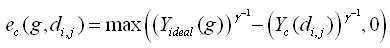
수학식 1에서, "g"는 계조 레벨을, "di ,j"는 (i,j)번째 블럭의 디밍값을, "γ"는 감마값(예컨대, 2.2)을 각각 나타낸다.In
한편, 광원들에 대한 국부적 디밍시, 상대적으로 낮은 계조에서는 도 4와 같이 해당 블럭에서 목표로 했던 휘도보다 더 높은 밝기를 나타내게 된다. 이는 액정층이 빛을 완전히 차단하지 못하여 해당 블럭의 밝기가 이웃한 블럭들의 밝기로부터 영향을 받는데 기인된다. 이러한 빛샘 현상을 라이트 리키지(Light leakage)라고 하며, 블럭별 리키지 오차는 아래의 수학식 2를 통해 구해진다. On the other hand, at the time of local dimming with respect to the light sources, at a relatively low gradation, as shown in FIG. 4, the brightness is higher than the target brightness in the corresponding block. This is because the liquid crystal layer does not completely block the light, and the brightness of the corresponding block is influenced by the brightness of neighboring blocks. This light leakage phenomenon is called light leakage, and the leakage error per block is obtained by the following equation (2).

수학식 2에서, "g"는 계조 레벨을, "di ,j"는 (i,j)번째 블럭의 디밍값을, "γ"는 감마값(예컨대, 2.2)을 각각 나타낸다.In Equation (2), "g" represents a gradation level, "d i , j " represents a dimming value of the (i, j) th block, and "γ" represents a gamma value (eg 2.2).
해당 블럭에서, 광원들의 밝기를 감소시키면 빛샘 현상은 개선되지만 클립핑 현상이 두드러진다. 반면, 광원들의 밝기를 증가시키면 클립핑 현상은 개선되지만 빛샘 현상이 두드러진다. 따라서, 해당 블럭에서 클립핑 양과 리키지 양을 적절히 조절할 수 있는 디밍 듀티를 찾는 것이 중요하다. In this block, when the brightness of the light sources is reduced, the light leakage phenomenon is improved, but the clipping phenomenon becomes conspicuous. On the other hand, if the brightness of the light sources is increased, the clipping phenomenon is improved, but the light leakage phenomenon becomes conspicuous. Therefore, it is important to find the dimming duty that can appropriately adjust the amount of clipping and the amount of leaking in the block.
이를 위해, 오차 산출부(142)는 아래의 수학식 3과 같이 클립핑 오차에 히스토그램 분석부(141)로부터의 계조별 히스토그램 값을 곱하여 블럭별 클립핑 양(Dc(i,j))을 구한다.To this end, the

수학식 3에서, n(g)는 계조별 히스토그램 분석값으로서, 계조 레벨 g를 갖는 픽셀 개수를 나타낸다.In Equation (3), n (g) represents the number of pixels having the gradation level g as a histogram analysis value by gradation.
또한, 오차 산출부(142)는 아래의 수학식 4와 같이 리키지 오차에 히스토그램 분석부(141)로부터의 계조별 히스토그램 값을 곱하여 블럭별 리키지 양(Dj(i,j)) 을 구한다.The

수학식 4에서, n(g)는 계조별 히스토그램 분석값으로서, 계조 레벨 g를 갖는 픽셀 개수를 나타낸다.In Equation (4), n (g) represents the number of pixels having the gradation level g as a histogram analysis value by gradation.
휘도 산출부(143)는 영상 데이터(RGB)를 한 프레임 단위로 입력받아 각 블럭에 해당하는 영상 데이터(RGB)의 평균 휘도값과 최대 휘도값을 산출하고, 이 블럭별 평균 휘도값과 최대 휘도값을 가중치상부 산출부(144)에 공급한다.The
가중치상부 산출부(144)는 해당 블럭의 최대 휘도값에 비례하고 이웃 블럭들의 평균 휘도값에 반비례하는 함수에 의해 결정되는 가중치상수를 블럭별로 산출한다. (i,j)번째 블럭의 가중치상수(αi,j)는 아래의 수학식 5를 통해 구해진다.The weighting

수학식 5에서, "MAX(i,j)"는 (i,j)번째 블럭의 최대 휘도값을, "APL(i,j)"은 ((i,j)번째 블럭에 포함되는 픽셀들의 휘도합)/(i,j)번째 블럭에 포함되는 픽셀들의 총 개수)로서, (i,j)번째 블럭의 평균 휘도값을, "M"은 (i,j)번째 블럭과 이웃 블럭들을 포함한 매크로 블럭의 가로 및 세로 사이즈를 각각 나타낸다. 여기서, 매크로 블럭의 사이즈 "M"은 도 5와 같이 (i,j)번째 블럭의 밝기에 영향을 미치는 이웃 블럭들의 개수(a,b)에 따라 소정의 값으로 미리 결정될 수 있다. 수학식 5에서, 분모는 이웃 블럭들의 평균 휘도값을 나타낸다.In Equation (5), " MAX (i, j) "represents the maximum luminance value of the (i, j) th block and" APL (I, j) th block and the neighboring blocks (i, j) th block, the average luminance value of the (i, j) And the horizontal and vertical sizes of the block, respectively. Here, the size "M" of the macroblock may be predetermined to a predetermined value according to the number (a, b) of neighboring blocks that affect the brightness of the (i, j) th block as shown in FIG. In Equation (5), the denominator represents an average luminance value of neighboring blocks.
도 5에서 명확히 알 수 있듯이, 해당 블럭의 가중치상수는 그 블럭의 최대 휘도값에 비례하고 이웃 블럭들의 평균 휘도값에 반비례하도록 결정된다. 캄캄한 밤하늘에 별이 빛나는 경우와 같이, 해당 블럭의 평균 휘도값이 매우 낮다고 하더라도 그 안에 매우 밝은 영역이 있을 수 있다. 이러한 경우, 종래와 같이 평균 휘도값에 따라 해당 블럭의 광원들 밝기를 감소시키게 되면 별이 사라지는 문제가 생긴다. 따라서, 해당 블럭의 가중치상수는 그 블럭의 최대 휘도값에 비례하는 값으로 결정됨으로써, 평균 휘도값이 낮은 블럭에서 고휘도 데이터의 밝기를 보상한다.5, the weighting constant of the block is determined to be proportional to the maximum luminance value of the block and inversely proportional to the average luminance value of the neighboring blocks. Even if the average luminance value of the block is very low, such as when a star shines in a dark night sky, there may be a very bright region in it. In this case, if the brightness of the light sources of the block is decreased according to the average luminance value as in the conventional case, the problem of the star disappears. Accordingly, the weight constant of the block is determined as a value proportional to the maximum luminance value of the block, thereby compensating for the brightness of the high luminance data in the block having the low average luminance value.
또한, 이웃 블럭들에 의한 빛샘의 영향으로 이웃 블럭들이 밝으면 해당 블럭도 일정 비율만큼 밝아지게 된다. 따라서, 해당 블럭의 가중치상수는 이웃 블럭들의 평균 휘도값에 반비례하는 값으로 결정됨으로써, 이웃 블럭들에 의한 빛샘 정도를 줄인다.Also, if the neighboring blocks are bright due to the influence of the light leakage caused by the neighboring blocks, the corresponding block becomes bright by a certain ratio. Therefore, the weight constant of the block is determined to be inversely proportional to the average luminance value of neighboring blocks, thereby reducing the degree of light leakage by neighboring blocks.
디밍 컨트롤부(145)는 오차 산출부(142)로부터의 블럭별 클랩핑 양 및 리키지 양과, 가중치상부 산출부(144)로부터의 블럭별 가중치상수를 이용하여 디밍 제어신호의 디밍 듀티를 제어한다. 디밍 컨트롤부(145)는 해당 블럭의 클랩핑 양에 그 블럭의 가중치상수를 곱한 양과, 그 블럭의 리키지 양을 서로 비교한다. 비교 결과 상기 리키지 양이 상기 곱한 양보다 크면, 디밍 컨트롤부(145)는 디밍 듀티가 미리 정해진 소정값 만큼 감소되도록 해당 블럭의 디밍 제어신호를 조정한 후, 이 조정된 디밍 제어신호를 오차 산출부(142)로 피드백시킨다. 반면, 상기 리키지 양이 상기 곱한 양보다 작으면, 디밍 컨트롤부(145)는 디밍 듀티가 미리 정해진 소정값 만큼 증가되도록 해당 블럭의 디밍 제어신호를 조정한 후, 이 조정된 디밍 제어신호를 오차 산출부(142)로 피드백시킨다. 이러한 피드백 과정을 거쳐 상기 곱한 양과 상기 리키지 양이 서로 같아지면, 디밍 컨트롤부(145)는 그때의 디밍 듀티를 최적 디밍 듀티로 결정하고, 이 최적 디밍 듀티를 포함한 디밍 제어신호를 PWM 생성부(146)로 출력한다.The dimming
PWM 생성부(146)는 디밍 컨트롤부(145)로부터의 디밍 제어신호에 응답하여 최적 디밍 듀티를 갖는 PWM 신호를 생성한다. The
도 6은 본 발명 따른 효과를 종래 기술들과 비교한 실험 결과이다.FIG. 6 shows experimental results comparing the effects of the present invention with the prior art.
도 6의 (a)는 영상 데이터에 상관없이 백라이트 유닛의 모든 광원들을 온 시켰을 때의 표시 영상으로서, 화면의 전 영역에서 라이트 리키지가 심각하여 표시 영상의 콘트라스트 특성이 매우 나쁘다. 도 6의 (b)는 종래 AFLC 기술을 적용하여 각 블럭의 평균 휘도값에 따라 광원들 휘도를 조절했을 때의 표시 영상으로서, 클립핑 문제로 별들이 거의 나타나지 않게 되어 디테일 한 영상 표현이 어렵게 된다. 도 6의 (c)는 각 블럭의 최대 휘도값에 따라 광원들 휘도를 조절했을 때의 표시 영상으로서, 별들이 표시되는 부분에서 여전히 라이트 리키지가 발생되어 콘트라스트 특성이 나쁘다.6A is a display image when all the light sources of the backlight unit are turned on irrespective of the image data, and the light leakage is severe in the entire area of the screen, and the contrast characteristic of the display image is very bad. FIG. 6 (b) is a display image obtained by adjusting the luminance of the light sources according to the average luminance value of each block by applying the conventional AFLC technique. As a result, stars hardly appear due to clipping problem, making detailed image representation difficult. FIG. 6C shows a display image when luminance of the light sources is adjusted in accordance with the maximum luminance value of each block, in which the light is still generated at the portion where the stars are displayed, and the contrast characteristic is bad.
반면, 도 6의 (d)는 본 발명에 따른 표시 영상으로서, 해당 블럭의 최대 휘 도값에 비례하고 이웃 블럭들의 평균 휘도값에 반비례하도록 결정되는 가중치상수를 이용하여 각 블럭의 광원들 휘도를 조절함으로써 도 6의 (c) 및 (d)에 비해 라이트 리키지를 거의 발생시키지 않으면서 즉, 높은 콘트라스트 특성을 가지면서도 디테일 한 영상 표현이 가능해 진다.6 (d) is a display image according to the present invention, in which the luminance of each block is adjusted by using a weighting constant determined in proportion to the maximum luminance value of the block and inversely proportional to the average luminance value of neighboring blocks 6 (c) and 6 (d), it is possible to display a detailed image while having high contrast characteristics, that is, without generating light leakage.
도 7은 본 발명의 실시예에 따른 액정표시장치의 구동방법을 보여준다.7 illustrates a method of driving a liquid crystal display according to an embodiment of the present invention.
도 7을 참조하면, 이 구동방법은 영상 데이터(RGB)가 입력되면(S1), 입력 영상 데이터(RGB)를 한 프레임 단위로 분석하여 각 블럭에 해당하는 영상 데이터(RGB)의 계조별 히스토그램 값을 산출한다(S2).Referring to FIG. 7, in this driving method, when the image data RGB is inputted S1, the input image data RGB are analyzed in units of one frame and the histogram values of the gradation of the image data RGB (S2).
이 구동방법은 피드백되는 디밍 제어신호에 따라 디밍한 후 해당 블럭에서의 클랩핑 양과 리키지 양을 산출한다(S3). 여기서, 클랩핑 양은, 해당 블럭에서 디밍으로 인한 광원들의 밝기 감소에 대응되는 클립핑 오차에, 상기 계조별 히스토그램 값이 곱해짐으로써 얻어진다. 리키지 양은, 디밍시 이웃한 블럭들의 밝기에 따른 해당 블럭의 밝기 변화에 대응되는 리키지 오차에, 상기 계조별 히스 히스토그램 값이 곱해짐으로써 얻어진다.In this driving method, dimming is performed according to the feedback dimming control signal, and the amount of clipping and the amount of leakage in the corresponding block are calculated (S3). Here, the amount of clapping is obtained by multiplying the clipping error corresponding to the brightness reduction of the light sources due to dimming in the corresponding block, by the histogram value by the gradation. The amount of leakage is obtained by multiplying the luminance error corresponding to the brightness change of the corresponding block according to the brightness of neighboring blocks at the time of dimming by the value of the histogram by hierarchy.
이 구동방법은 영상 데이터(RGB)를 한 프레임 단위로 입력받아 각 블럭에 해당하는 영상 데이터(RGB)의 평균 휘도값과 최대 휘도값을 산출한다(S4).In this driving method, the image data (RGB) is input in units of one frame, and the average luminance value and the maximum luminance value of the image data (RGB) corresponding to each block are calculated (S4).
이 구동방법은 해당 블럭의 최대 휘도값에 비례하고 이웃 블럭들의 평균 휘도값에 반비례하는 함수에 결정되는 가중치상수를 블럭별로 산출한다(S5). In this driving method, a weighting coefficient determined in a function in proportion to a maximum luminance value of the block and inversely proportional to an average luminance value of neighboring blocks is calculated for each block (S5).
이 구동방법은 해당 블럭의 클랩핑 양에 그 블럭의 가중치상수를 곱한 양과, 그 블럭의 리키지 양을 서로 비교한다(S6). 상기 비교 결과 상기 리키지 양이 상기 곱한 양보다 크면(S6의 아니오, 및 S7의 예), 이 구동방법은 디밍 듀티가 미리 정해진 소정값 만큼 감소되도록 디밍 제어신호를 조정한 후(S8), 이 조정된 디밍 제어신호를 S3 단계로 피드백시킨다. 반면, 상기 리키지 양이 상기 곱한 양보다 작으면(S6의 아니오, 및 S7의 아니오), 이 구동방법은 디밍 듀티가 미리 정해진 소정값 만큼 증가되도록 디밍 제어신호를 조정한 후(S9), 이 조정된 디밍 제어신호를 S3 단계로 피드백시킨다. In this driving method, the amount by which the amount of clapping of the block is multiplied by the weighting constant of the block and the amount of the retained amount of the block are compared with each other (S6). If the amount of leakage is greater than the multiplied amount (NO in S6 and S7), the driving method adjusts the dimming control signal so that the dimming duty is reduced by a predetermined value (S8) And feeds the adjusted dimming control signal to the step S3. On the other hand, if the amount of the leakage is smaller than the multiplied amount (NO in S6 and NO in S7), the driving method adjusts the dimming control signal so that the dimming duty is increased by a predetermined value (S9) And feeds the adjusted dimming control signal to the step S3.
이러한 피드백 과정을 거쳐 상기 곱한 양과 상기 리키지 양이 서로 같아지면(S6의 예), 이 구동방법은 그때의 디밍 듀티를 최적 디밍 듀티로 결정한 후, 이 최적 디밍 듀티에 맞춰 PWM 신호의 듀티를 조정한다(S10). PWM 신호의 듀티 조정에 의해 광원들의 밝기는 국부적으로 제어된다.If the multiplication amount and the amount of the rekey are equal to each other (S6), the driving method determines the dimming duty at that time as the optimum dimming duty and then adjusts the duty of the PWM signal in accordance with the optimum dimming duty. (S10). By adjusting the duty of the PWM signal, the brightness of the light sources is locally controlled.
상술한 바와 같이, 본 발명에 따른 액정표시장치 및 그 구동방법은 표시 영상을 소정 개수의 논리적 블럭으로 분할하고, 각 블럭의 클랩핑 양과 리키지 양을, 각 블럭의 최대 휘도값에 비례하고 이웃 블럭들의 평균 휘도값에 반비례하는 가중치상수를 고려하여 비교한 후, 해당 블럭의 클랩핑 양에 해당 가중치상수를 곱한 양과 해당 블럭의 리키지 양이 서로 같아질 때의 디밍 듀티로 해당 블럭의 광원들을 구동한다. 그 결과, 본 발명에 따른 액정표시장치 및 그 구동방법은 평균 휘도값이 낮은 블럭에서도 고휘도 데이터의 밝기를 보상할 수 있고, 이로 인해 높은 콘트라스트 비를 확보할 수 있다.As described above, the liquid crystal display and the driving method thereof according to the present invention divide a display image into a predetermined number of logical blocks, and calculate a clipping amount and a leakage amount of each block in proportion to the maximum luminance value of each block, After comparing the weighting factor in inverse proportion to the average luminance value of the blocks, the dimming duty when the amount of the clapping of the block multiplied by the corresponding weighting constant is equal to the amount of the corresponding block, . As a result, in the liquid crystal display device and the driving method thereof according to the present invention, the brightness of the high-luminance data can be compensated even in the block having the low average luminance value, thereby ensuring a high contrast ratio.
이상 설명한 내용을 통해 당업자라면 본 발명의 기술사상을 일탈하지 아니하는 범위에서 다양한 변경 및 수정이 가능함을 알 수 있을 것이다. 따라서, 본 발명의 기술적 범위는 명세서의 상세한 설명에 기재된 내용으로 한정되는 것이 아니라 특허 청구의 범위에 의해 정하여져야만 할 것이다.It will be apparent to those skilled in the art that various modifications and variations can be made in the present invention without departing from the spirit or scope of the invention. Therefore, the technical scope of the present invention should not be limited to the contents described in the detailed description of the specification, but should be defined by the claims.
도 1은 본 발명의 실시예에 따른 액정표시장치를 보여주는 블럭도.1 is a block diagram showing a liquid crystal display device according to an embodiment of the present invention.
도 2는 한 프레임 분의 영상 데이터가 면광원의 분할 개수에 맞춰 소정 개수의 분할되는 일 예를 보여주는 도면.Fig. 2 is a diagram showing an example in which image data for one frame is divided into a predetermined number in accordance with the number of division of the surface light source.
도 3은 백라이트 제어회로를 상세히 보여주는 블럭도.3 is a block diagram showing the backlight control circuit in detail;
도 4는 국부적 디밍시 발생되는 클립핑 오차와 리키지 오차를 보여주는 도면.Fig. 4 is a view showing clipping error and latitude error generated in local dimming; Fig.
도 5는 해당 블럭과 이웃 블럭들을 포함한 매크로 블럭을 보여주는 도면.5 is a view showing a macroblock including a corresponding block and neighboring blocks;
도 6은 본 발명 따른 효과를 종래 기술들과 비교한 실험 결과를 보여주는 도면.Figure 6 shows experimental results comparing the effects of the present invention with the prior art.
도 7은 본 발명의 실시예에 따른 액정표시장치의 구동방법을 보여주는 흐름도.7 is a flowchart illustrating a method of driving a liquid crystal display according to an embodiment of the present invention.
< 도면의 주요 부분에 대한 부호의 설명 >Description of the Related Art
10 : 액정표시패널 11 : 타이밍 콘트롤러10: liquid crystal display panel 11: timing controller
12 : 데이터 구동회로 13 : 게이트 구동회로12: data driving circuit 13: gate driving circuit
14 : 광원 제어회로 15 : 광원 구동회로14: light source control circuit 15: light source driving circuit
16 : 백라이트 유닛 141 : 히스토그램 분석부16: Backlight unit 141: Histogram analysis unit
142 : 오차 산출부 143 : 휘도 산출부142: error calculator 143: luminance calculator
144 : 가중치상부 산출부 145 : 디밍 컨트롤부144: upper weight calculation unit 145: dimming control unit
146 : PWM 생성부 146: PWM generation unit
Claims (14)
Priority Applications (1)
| Application Number | Priority Date | Filing Date | Title |
|---|---|---|---|
| KR1020090106580A KR101604493B1 (en) | 2009-11-05 | 2009-11-05 | Liquid crystal display and driving method of thereof |
Applications Claiming Priority (1)
| Application Number | Priority Date | Filing Date | Title |
|---|---|---|---|
| KR1020090106580A KR101604493B1 (en) | 2009-11-05 | 2009-11-05 | Liquid crystal display and driving method of thereof |
Publications (2)
| Publication Number | Publication Date |
|---|---|
| KR20110049529A KR20110049529A (en) | 2011-05-12 |
| KR101604493B1 true KR101604493B1 (en) | 2016-03-18 |
Family
ID=44360655
Family Applications (1)
| Application Number | Title | Priority Date | Filing Date |
|---|---|---|---|
| KR1020090106580A Active KR101604493B1 (en) | 2009-11-05 | 2009-11-05 | Liquid crystal display and driving method of thereof |
Country Status (1)
| Country | Link |
|---|---|
| KR (1) | KR101604493B1 (en) |
Families Citing this family (4)
| Publication number | Priority date | Publication date | Assignee | Title |
|---|---|---|---|---|
| KR102408806B1 (en) * | 2015-08-31 | 2022-06-13 | 엘지디스플레이 주식회사 | Liquid Display Device And Method Of Driving The Same |
| KR102589356B1 (en) * | 2016-12-01 | 2023-10-13 | 삼성전자주식회사 | Display apparatus and controlling method thereof |
| CN119559908B (en) * | 2025-01-03 | 2025-11-11 | 江西寒松连接系统有限公司 | Vehicle-mounted LED backlight source and control method |
| CN120708550A (en) * | 2025-08-15 | 2025-09-26 | 东莞德闳显示技术有限公司 | A low-latency Mini LED backlight control method and system |
Citations (1)
| Publication number | Priority date | Publication date | Assignee | Title |
|---|---|---|---|---|
| KR100751461B1 (en) * | 2006-08-02 | 2007-08-23 | 경북대학교 산학협력단 | LCD and apparatus for reducing power consumption by adjusting backlight brightness |
-
2009
- 2009-11-05 KR KR1020090106580A patent/KR101604493B1/en active Active
Patent Citations (1)
| Publication number | Priority date | Publication date | Assignee | Title |
|---|---|---|---|---|
| KR100751461B1 (en) * | 2006-08-02 | 2007-08-23 | 경북대학교 산학협력단 | LCD and apparatus for reducing power consumption by adjusting backlight brightness |
Also Published As
| Publication number | Publication date |
|---|---|
| KR20110049529A (en) | 2011-05-12 |
Similar Documents
| Publication | Publication Date | Title |
|---|---|---|
| KR101588901B1 (en) | Liquid crystal display and its local dimming control method | |
| TWI452566B (en) | Liquid crystal display and scanning backlight driving method thereof | |
| US8803925B2 (en) | Liquid crystal display and scanning back light driving method thereof | |
| KR101324372B1 (en) | Liquid crystal display and scanning back light driving method thereof | |
| TWI518661B (en) | Liquid crystal display | |
| KR101295882B1 (en) | Liquid crystal display and local dimming control method of thereof | |
| KR101318444B1 (en) | Method of compensating pixel data and liquid crystal display | |
| US8816953B2 (en) | Liquid crystal display and scanning back light driving method thereof | |
| KR101623592B1 (en) | Liquid Crystal Display Device | |
| KR101731118B1 (en) | Liquid crystal display and global dimming control method of thereof | |
| KR101644189B1 (en) | Liquid crystal display and dimming controlling method of thereof | |
| KR101705903B1 (en) | Liquid crystal display | |
| KR102022639B1 (en) | Liquid crystal display and dimming control method of thereof | |
| KR101604493B1 (en) | Liquid crystal display and driving method of thereof | |
| KR20110061173A (en) | LCD and Local Dimming Control Method | |
| KR101633110B1 (en) | Liquid crystal display and dimming control method of thereof | |
| KR102438248B1 (en) | Dimming control circuit, liquid crystal display including the dimming control circuit, and dimming control method of the liquid crystal display | |
| KR101577834B1 (en) | Liquid crystal display and its local dimming control method | |
| KR101777867B1 (en) | Liquid crystal display and driving method thereof | |
| KR20110066723A (en) | LCD and its quality control method |
Legal Events
| Date | Code | Title | Description |
|---|---|---|---|
| PA0109 | Patent application |
Patent event code: PA01091R01D Comment text: Patent Application Patent event date: 20091105 |
|
| PG1501 | Laying open of application | ||
| PA0201 | Request for examination |
Patent event code: PA02012R01D Patent event date: 20141031 Comment text: Request for Examination of Application Patent event code: PA02011R01I Patent event date: 20091105 Comment text: Patent Application |
|
| PE0902 | Notice of grounds for rejection |
Comment text: Notification of reason for refusal Patent event date: 20150715 Patent event code: PE09021S01D |
|
| E701 | Decision to grant or registration of patent right | ||
| PE0701 | Decision of registration |
Patent event code: PE07011S01D Comment text: Decision to Grant Registration Patent event date: 20160130 |
|
| GRNT | Written decision to grant | ||
| PR0701 | Registration of establishment |
Comment text: Registration of Establishment Patent event date: 20160311 Patent event code: PR07011E01D |
|
| PR1002 | Payment of registration fee |
Payment date: 20160311 End annual number: 3 Start annual number: 1 |
|
| PG1601 | Publication of registration | ||
| PR1001 | Payment of annual fee |
Payment date: 20190215 Start annual number: 4 End annual number: 4 |
|
| FPAY | Annual fee payment |
Payment date: 20200219 Year of fee payment: 5 |
|
| PR1001 | Payment of annual fee |
Payment date: 20200219 Start annual number: 5 End annual number: 5 |
|
| PR1001 | Payment of annual fee |
Payment date: 20210215 Start annual number: 6 End annual number: 6 |
|
| PR1001 | Payment of annual fee |
Payment date: 20220210 Start annual number: 7 End annual number: 7 |
|
| PR1001 | Payment of annual fee |
Payment date: 20230215 Start annual number: 8 End annual number: 8 |
|
| PR1001 | Payment of annual fee |
Payment date: 20240215 Start annual number: 9 End annual number: 9 |
|
| PR1001 | Payment of annual fee |
Payment date: 20250218 Start annual number: 10 End annual number: 10 |