KR101597573B1 - Uplink transmission method of control information - Google Patents
Uplink transmission method of control information Download PDFInfo
- Publication number
- KR101597573B1 KR101597573B1 KR1020090003311A KR20090003311A KR101597573B1 KR 101597573 B1 KR101597573 B1 KR 101597573B1 KR 1020090003311 A KR1020090003311 A KR 1020090003311A KR 20090003311 A KR20090003311 A KR 20090003311A KR 101597573 B1 KR101597573 B1 KR 101597573B1
- Authority
- KR
- South Korea
- Prior art keywords
- slot
- frequency resource
- sequence
- symbol
- control channel
- Prior art date
- Legal status (The legal status is an assumption and is not a legal conclusion. Google has not performed a legal analysis and makes no representation as to the accuracy of the status listed.)
- Active
Links
Images


Classifications
-
- H—ELECTRICITY
- H04—ELECTRIC COMMUNICATION TECHNIQUE
- H04L—TRANSMISSION OF DIGITAL INFORMATION, e.g. TELEGRAPHIC COMMUNICATION
- H04L1/00—Arrangements for detecting or preventing errors in the information received
- H04L1/0001—Systems modifying transmission characteristics according to link quality, e.g. power backoff
- H04L1/0023—Systems modifying transmission characteristics according to link quality, e.g. power backoff characterised by the signalling
- H04L1/0028—Formatting
-
- H—ELECTRICITY
- H04—ELECTRIC COMMUNICATION TECHNIQUE
- H04L—TRANSMISSION OF DIGITAL INFORMATION, e.g. TELEGRAPHIC COMMUNICATION
- H04L1/00—Arrangements for detecting or preventing errors in the information received
- H04L1/12—Arrangements for detecting or preventing errors in the information received by using return channel
- H04L1/16—Arrangements for detecting or preventing errors in the information received by using return channel in which the return channel carries supervisory signals, e.g. repetition request signals
- H04L1/1607—Details of the supervisory signal
-
- H—ELECTRICITY
- H04—ELECTRIC COMMUNICATION TECHNIQUE
- H04B—TRANSMISSION
- H04B7/00—Radio transmission systems, i.e. using radiation field
- H04B7/02—Diversity systems; Multi-antenna system, i.e. transmission or reception using multiple antennas
- H04B7/04—Diversity systems; Multi-antenna system, i.e. transmission or reception using multiple antennas using two or more spaced independent antennas
- H04B7/06—Diversity systems; Multi-antenna system, i.e. transmission or reception using multiple antennas using two or more spaced independent antennas at the transmitting station
- H04B7/0613—Diversity systems; Multi-antenna system, i.e. transmission or reception using multiple antennas using two or more spaced independent antennas at the transmitting station using simultaneous transmission
- H04B7/0615—Diversity systems; Multi-antenna system, i.e. transmission or reception using multiple antennas using two or more spaced independent antennas at the transmitting station using simultaneous transmission of weighted versions of same signal
- H04B7/0619—Diversity systems; Multi-antenna system, i.e. transmission or reception using multiple antennas using two or more spaced independent antennas at the transmitting station using simultaneous transmission of weighted versions of same signal using feedback from receiving side
- H04B7/0621—Feedback content
- H04B7/0632—Channel quality parameters, e.g. channel quality indicator [CQI]
-
- H—ELECTRICITY
- H04—ELECTRIC COMMUNICATION TECHNIQUE
- H04B—TRANSMISSION
- H04B7/00—Radio transmission systems, i.e. using radiation field
- H04B7/02—Diversity systems; Multi-antenna system, i.e. transmission or reception using multiple antennas
- H04B7/04—Diversity systems; Multi-antenna system, i.e. transmission or reception using multiple antennas using two or more spaced independent antennas
- H04B7/06—Diversity systems; Multi-antenna system, i.e. transmission or reception using multiple antennas using two or more spaced independent antennas at the transmitting station
- H04B7/0613—Diversity systems; Multi-antenna system, i.e. transmission or reception using multiple antennas using two or more spaced independent antennas at the transmitting station using simultaneous transmission
- H04B7/0615—Diversity systems; Multi-antenna system, i.e. transmission or reception using multiple antennas using two or more spaced independent antennas at the transmitting station using simultaneous transmission of weighted versions of same signal
- H04B7/0619—Diversity systems; Multi-antenna system, i.e. transmission or reception using multiple antennas using two or more spaced independent antennas at the transmitting station using simultaneous transmission of weighted versions of same signal using feedback from receiving side
- H04B7/0636—Feedback format
- H04B7/0639—Using selective indices, e.g. of a codebook, e.g. pre-distortion matrix index [PMI] or for beam selection
-
- H—ELECTRICITY
- H04—ELECTRIC COMMUNICATION TECHNIQUE
- H04L—TRANSMISSION OF DIGITAL INFORMATION, e.g. TELEGRAPHIC COMMUNICATION
- H04L5/00—Arrangements affording multiple use of the transmission path
- H04L5/003—Arrangements for allocating sub-channels of the transmission path
- H04L5/0044—Allocation of payload; Allocation of data channels, e.g. PDSCH or PUSCH
-
- H—ELECTRICITY
- H04—ELECTRIC COMMUNICATION TECHNIQUE
- H04L—TRANSMISSION OF DIGITAL INFORMATION, e.g. TELEGRAPHIC COMMUNICATION
- H04L5/00—Arrangements affording multiple use of the transmission path
- H04L5/003—Arrangements for allocating sub-channels of the transmission path
- H04L5/0048—Allocation of pilot signals, i.e. of signals known to the receiver
Landscapes
- Engineering & Computer Science (AREA)
- Signal Processing (AREA)
- Computer Networks & Wireless Communication (AREA)
- Quality & Reliability (AREA)
- Mobile Radio Communication Systems (AREA)
- Physics & Mathematics (AREA)
- Mathematical Physics (AREA)
Abstract
본 발명은 무선 통신 시스템에 관한 것이다. 구체적으로, 본 발명은 무선 통신 시스템에서 단말이 제어정보를 상향링크 전송하는 방법에 있어서, 심볼 공간에 분산되며 제어정보에 대응되는 복수의 포인트 중에서 특정 포인트를 선택하되, 상기 심볼 공간은 변조 차원 및 시퀀스 차원을 포함하는 단계와, 상기 특정 포인트에 대응하는 신호를 SC-FDMA(single carrier-frequency division multiple access) 심볼을 포함하는 제어채널에 맵핑하는 단계와, 상기 제어채널을 전송하는 단계를 포함하는 제어정보의 상향링크 전송 방법에 관한 것이다.
The present invention relates to a wireless communication system. In particular, the present invention provides a method for uplink transmission of control information by a mobile station in a wireless communication system, the method comprising: selecting a specific point among a plurality of points distributed in a symbol space and corresponding to control information, Mapping a signal corresponding to the particular point to a control channel including a single carrier-frequency division multiple access (SC-FDMA) symbol, and transmitting the control channel. And an uplink transmission method of control information.
Description
본 발명은 무선 통신 시스템에 관한 것이다. 구체적으로, 본 발명은 무선 통신 시스템에서 제어정보를 상향링크 전송하는 방법에 관한 것이다.The present invention relates to a wireless communication system. More particularly, the present invention relates to a method for uplink transmission of control information in a wireless communication system.
차세대 무선 통신 시스템은 제한된 무선자원을 이용하여 고품질의 멀티미디어 데이터를 고속으로 전송할 수 있어야 한다. 대역폭이 제한된 무선 채널에서 이를 가능하게 하기 위해서는 주파수 효율(spectral efficiency)을 극대화하면서 고속 전송시 발생하는 심볼간 간섭(inter-symbol interference) 및 주파수 선택적 페이딩(frequency selective fading)을 극복해야 한다.The next generation wireless communication system should be able to transmit high quality multimedia data at high speed by using limited radio resources. In order to enable this in a bandwidth-limited radio channel, it is necessary to overcome inter-symbol interference and frequency selective fading occurring during high-speed transmission while maximizing spectral efficiency.
무선 통신 시스템의 성능을 향상시키기 위해 기지국과 단말 사이의 채널 상태(channel condition)을 이용하는 폐루프(closed-loop) 전송 기법이 등장하고 있다. 적응적 변조 및 코딩(Adaptive Modulation and Coding; AMC) 기법은 귀환되는 채널 상태 정보를 이용하여 기지국에서 변조 및 코딩 방식(modulation and coding scheme, MCS)을 조절하여 링크 성능을 증가시키는 기술이다.In order to improve the performance of a wireless communication system, a closed-loop transmission technique using a channel condition between a base station and a mobile station has appeared. Adaptive Modulation and Coding (AMC) is a technique for improving link performance by adjusting modulation and coding scheme (MCS) at a base station using feedback channel state information.
따라서, 기지국은 각 단말로부터 하향링크 채널 상태를 수신하여 주파수 선 택적 스케줄링을 수행할 수 있다. 다양한 상향링크 제어 정보를 상향링크 제어채널을 통해 전송된다. 상향링크 제어신호로는 HARQ(hybrid automatic repeat request)를 수행하기 위한 ACK(Acknowledgement)/NACK(Not-Acknowledgement) 신호, 하향링크 채널 품질을 가리키는 CQI(Channel Quality Indicator), PMI(Precoding Matrix Index), RI(Rank Indicator) 등 여러 가지 종류가 있다.Therefore, the BS can perform the frequency selective scheduling by receiving the downlink channel status from each UE. Various uplink control information is transmitted through the uplink control channel. The uplink control signal includes ACK (Acknowledgment) / NACK (Not-Acknowledgment) signals for performing hybrid automatic repeat request (HARQ), Channel Quality Indicator (CQI) indicating a downlink channel quality, Precoding Matrix Index (PMI) RI (Rank Indicator) and so on.
상향링크 전송은 단말에서 이루어지므로, 배터리 소모를 작게 하기 위해 낮은 PAPR(Peak-to-Average Power Ratio)을 갖도록 하는 것이 중요하다. 이를 위해, 3GPP(3rd Generation Partnership Project) LTE(Long-term Evolution)는 단일 반송파(single carrier) 특성을 갖는 변조 방식을 사용하여 상향링크 전송을 수행한다.Since uplink transmission is performed in the UE, it is important to have a low peak-to-average power ratio (PAPR) in order to reduce battery consumption. To this end, the 3rd Generation Partnership Project (3GPP) LTE (Long-term Evolution) performs uplink transmission using a modulation scheme having a single carrier characteristic.
IMT-Advanced에서 시스템 동작은 기존의 단일 반송파(single carrier) 기반의 OFDM 전송방식에 추가하여 광대역 통신을 가능하게 하기 위해 다중 반송파(multiple carrier) 기반의 전송방식을 사용할 수 있다. 또한, 단일 반송파와 다중 반송파 기반의 전송방식을 통합하여 송수신하는 방안을 강구할 수 있다. 단말은 각 반송파에서 선택적으로 동작할 수도 있고, 동시에 여러 반송파를 이용해서 송수신할 수도 있다. 이러한 상황에서, 상향링크 제어채널은 다중 대역에 대한 채널 정보를 전달해야 하는 부담을 가지게 되고 이는 상향링크 제어채널의 심볼 공간에 대한 부담으로 작용한다. 또한, IMT-Advanced는 쓰루풋을 증가시키기 위해 상향링크에서도 다중 안테나(multi-input multi-output; MIMO)를 사용할 것이므로, 전송 안테나 수의 증가에 따라 정보량이 증가하는 부분도 상향링크 제어채널의 심볼 스페이스에 대한 부담으로 작용한다.In the IMT-Advanced system operation, a multiple carrier based transmission scheme can be used to enable broadband communication in addition to the existing single carrier based OFDM transmission scheme. In addition, a method of transmitting and receiving a single carrier and a multi-carrier based transmission scheme can be integrated. The terminal may selectively operate on each carrier wave, and may also transmit and receive using several carrier waves at the same time. In this situation, the uplink control channel has a burden of transmitting channel information for multiple bands, which acts as a burden on the symbol space of the uplink control channel. Also, because the IMT-Advanced uses multi-input multi-output (MIMO) in the uplink to increase the throughput, a portion where the amount of information increases with an increase in the number of transmission antennas is also a symbol space .
또한, 사용자가 원하는 서비스품질(Quality of Service; QoS)를 보다 잘 충족시키고 커버리지 홀 등을 해소하기 위해, 임의로 온/오프가 가능한 임의 노드에 대한 논의가 진행되고 있다. 상기 임의 노드는 용량 보다는 쓰루풋에 초점을 맞춰 설계되고 있으며, 펨토 셀, 피코 셀 등을 포함한다. 펨토 셀은 일반적으로 서비스 반경이 30m 이내로서 가정, 사무실 등에 서비스를 제공할 수 있다. 피코 셀은 일반적으로 서비스 반경이 100m 이내로서 빌딩 내부에 서비스를 제공할 수 있다. 이러한 임의 노드는 일반적으로 0.1 와트 미만의 전력을 사용하여 신호를 하향 전송한 다. 위와 같이, 임의 노드는 커버러지가 작아서 단말과 기지국간의 채널이 플랫 페이딩(flat fading)에 가깝고, 임의 노드 내에서 단말이 고속으로 움직이는 것은 거의 불가능하다. 특히, 단말의 커버리지가 임의 노드의 커버리지 보다 길어질 수 있으므로 상향링크 제어채널을 보다 효율적으로 사용하는 것을 고려할 수 있다. In addition, a discussion is being made on an arbitrary node that can be turned on / off arbitrarily in order to better meet a desired quality of service (QoS) and to eliminate coverage holes and the like. The arbitrary node is designed to focus on throughput rather than capacity, and includes a femtocell, a picocell, and the like. Femtocells are generally able to provide services to homes, offices, etc. within a radius of 30 meters. The picocell is generally able to provide services inside the building with a service radius of less than 100 meters. These random nodes typically transmit signals downwards using less than 0.1 watts of power. As described above, since the coverage of a certain node is small, the channel between the terminal and the base station is close to flat fading, and it is almost impossible for the terminal to move at high speed in any node. In particular, since the coverage of the UE may be longer than the coverage of the arbitrary node, it may be considered to use the uplink control channel more efficiently.
본 발명은 상기한 바와 같은 종래기술의 문제점을 해결하기 위해 안출된 것으로서, 본 발명의 목적은 무선 통신 시스템에서 상향링크 제어채널을 통해 전송할 수 있는 정보량을 증가시키기 위한 다양한 방법을 제공하는 것이다.It is an object of the present invention to provide various methods for increasing the amount of information that can be transmitted through an uplink control channel in a wireless communication system.
본 발명의 다른 목적은 단일 반송파 기반의 상향링크 전송에서 다중 반송파 기반의 상향링크 전송으로 확장하는 경우에 상향링크 제어채널을 통해 전송할 수 있는 정보량을 증가시키기 위한 다양한 방법을 제공하는 것이다. Another object of the present invention is to provide various methods for increasing the amount of information that can be transmitted through an uplink control channel in case of extending from a single carrier based uplink transmission to a multicarrier based uplink transmission.
본 발명의 다른 목적은 단일 안테나 기반의 상향링크 전송에서 다중 안테나 기반의 상향링크 전송으로 확장하는 경우에 상향링크 제어채널을 통해 전송할 수 있는 정보량을 증가시키기 위한 다양한 방법을 제공하는 것이다. It is another object of the present invention to provide various methods for increasing the amount of information that can be transmitted through an uplink control channel in the case of extending from a single antenna based uplink transmission to a multiple antenna based uplink transmission.
본 발명의 다른 목적은 펨토 셀과 같은 임의 노드에서 상향링크 제어채널을 통해 전송할 수 있는 정보량을 증가시키기 위한 다양한 방법을 제공하는 것이다. It is another object of the present invention to provide various methods for increasing the amount of information that can be transmitted through an uplink control channel in an arbitrary node such as a femtocell.
본 발명에서 이루고자 하는 기술적 과제들은 이상에서 언급한 기술적 과제들로 제한되지 않으며, 언급하지 않은 또 다른 기술적 과제들은 아래의 기재로부터 본 발명이 속하는 기술분야에서 통상의 지식을 가진 자에게 명확하게 이해될 수 있을 것이다.It is to be understood that both the foregoing general description and the following detailed description are exemplary and explanatory and are not restrictive of the invention, unless further departing from the spirit and scope of the invention as defined by the appended claims. It will be possible.
본 발명의 일 양상은 무선 통신 시스템에서 단말이 제어정보를 상향링크 전송하는 방법에 있어서, 심볼 공간에 분산되며 제어정보에 대응되는 복수의 포인트 중에서 특정 포인트를 선택하되, 상기 심볼 공간은 변조 차원 및 시퀀스 차원을 포함하는 단계와, 상기 특정 포인트에 대응하는 신호를 SC-FDMA(single carrier-frequency division multiple access) 심볼을 포함하는 제어채널에 맵핑하는 단계와, 상기 제어채널을 전송하는 단계를 포함하는 제어정보의 상향링크 전송 방법을 제공하는 것이다. 바람직하게, 상기 특정 포인트는 상기 시퀀스 차원에 속해 있다.According to an aspect of the present invention, there is provided a method for uplink transmission of a control information in a wireless communication system, the method comprising: selecting a specific point among a plurality of points distributed in a symbol space and corresponding to control information, Mapping a signal corresponding to the particular point to a control channel including a single carrier-frequency division multiple access (SC-FDMA) symbol, and transmitting the control channel. And an uplink transmission method of control information. Preferably, the particular point belongs to the sequence dimension.
상기 시퀀스 차원은 직교 시퀀스, 의사-직교 시퀀스 또는 의사 잡음 시퀀스를 포함할 수 있다. 구체적으로, 상기 시퀀스 차원은 ZC(Zadoff-Chu), CAZAC(Constant amplitude zero autocorrelation waveform), 왈쉬(walsh), DFT(discrete fourier transform) 시퀀스를 포함할 수 있다.The sequence dimension may comprise an orthogonal sequence, a pseudo-orthogonal sequence or a pseudo noise sequence. Specifically, the sequence dimension may include ZC (Zadoff-Chu), CAZAC (Constant amplitude zero autocorrelation waveform), Walsh, and DFT (discrete fourier transform) sequences.
상기 심볼 영역은 주파수 차원을 더 포함할 수 있다. 구체적으로, 상기 주파수 차원은 부반송파 그룹, 채널, 서브밴드 또는 호핑 패턴을 포함할 수 있다.The symbol region may further include a frequency dimension. In particular, the frequency dimension may include a subcarrier group, a channel, a subband, or a hopping pattern.
본 발명의 실시예들에 따르면 다음과 같은 효과가 있다.According to the embodiments of the present invention, the following effects are obtained.
첫째, 무선 통신 시스템에서 상향링크 제어채널을 통해 전송할 수 있는 정보량을 증가시킬 수 있다.First, the amount of information that can be transmitted through the uplink control channel in the wireless communication system can be increased.
둘째, 단일 반송파에서 다중 반송파 기반의 상향링크 전송으로 확장하는 경우에 상향링크 제어채널을 통해 전송할 수 있는 정보량을 증가시킬 수 있다.Second, the amount of information that can be transmitted through the uplink control channel can be increased in the case of extending from a single carrier to an uplink transmission based on a multicarrier.
셋째, 단일 안테나에서 다중 안테나 기반의 상향링크 전송으로 확장하는 경 우에 상향링크 제어채널을 통해 전송할 수 있는 정보량을 증가시킬 수 있다.Third, if the single antenna is extended to the multi-antenna based uplink transmission, the amount of information that can be transmitted through the uplink control channel can be increased.
넷째, 펨토 셀과 같은 임의 노드에서 상향링크 제어채널을 통해 전송할 수 있는 정보량을 증가시킬 수 있다.Fourth, it is possible to increase the amount of information that can be transmitted through an uplink control channel in an arbitrary node such as a femtocell.
본 발명에서 얻을 수 있는 효과는 이상에서 언급한 효과들로 제한되지 않으며, 언급하지 않은 또 다른 효과들은 아래의 기재로부터 본 발명이 속하는 기술분야에서 통상의 지식을 가진 자에게 명확하게 이해될 수 있을 것이다.The effects obtained by the present invention are not limited to the above-mentioned effects, and other effects not mentioned can be clearly understood by those skilled in the art from the following description will be.
첨부된 도면을 참조하여 설명되는 본 발명의 바람직한 실시예들에 의해 본 발명의 구성, 작용 및 다른 특징들이 용이하게 이해될 수 있을 것이다. 이하에서 설명되는 실시예들은 본 발명의 기술적 특징이 적용된 예들이다.The structure, operation and other features of the present invention can be easily understood by the preferred embodiments of the present invention described with reference to the accompanying drawings. The embodiments described below are examples to which the technical features of the present invention are applied.
도 1는 SC-FDMA(single carrier-frequency division multiple access) 방식에 따른 송신기의 블록도를 예시한다.FIG. 1 illustrates a block diagram of a transmitter according to a single carrier-frequency division multiple access (SC-FDMA) scheme.
도 1을 참조하면, SC-FDMA 송신기는 DFT(Discrete Fourier Transform)를 수행하는 DFT 유닛(110), 부반송파 맵퍼(subcarrier mapper, 120) 및 IFFT(Inverse Fast Fourier Transform)를 수행하는 IFFT 유닛(130)을 포함한다.1, an SC-FDMA transmitter includes a
DFT 유닛(110)은 입력되는 시간 영역의 데이터에 DFT를 수행하여 주파수 영역 심볼을 출력한다. 부반송파 맵퍼(120)는 주파수 영역 심볼들을 각 부반송파에 맵핑시킨다. IFFT 유닛(130)은 입력되는 주파수 영역 심볼에 대해 IFFT를 수행하여 시간 영역 신호를 출력한다.The DFT
도 2는 본 발명의 실시예에 적용될 수 있는 무선 프레임의 구조를 예시한다.2 illustrates a structure of a radio frame that can be applied to an embodiment of the present invention.
도 2를 참조하면, 무선 프레임(radio frame)은 10개의 서브프레임(subframe)으로 구성되고, 서브프레임은 2개의 슬롯(slot)으로 구성된다. 서브 프레임이 전송되는 데 걸리는 시간을 TTI(transmission time interval)라고 한다. 예를 들어, 서브프레임의 길이는 1ms이고, 슬롯의 길이는 0.5ms일 수 있다. 슬롯은 시간 영역에서 복수의 SC-FDMA 심볼을 포함하고, 주파수 영역에서 다수의 자원블록(resource block)을 포함한다. 상술한 무선 프레임의 구조는 예시에 불과하고, 무선 프레임에 포함되는 서브프레임의 수 또는 서브프레임에 포함되는 슬롯의 수, 슬롯에 포함되는 SC-FDMA 심볼의 수는 다양하게 변경될 수 있다.Referring to FIG. 2, a radio frame is composed of 10 subframes, and a subframe is composed of 2 slots. The time taken for a subframe to be transmitted is called a transmission time interval (TTI). For example, the length of the subframe may be 1 ms and the length of the slot may be 0.5 ms. A slot includes a plurality of SC-FDMA symbols in a time domain and a plurality of resource blocks in a frequency domain. The above-described radio frame structure is merely an example, and the number of subframes included in a radio frame, the number of slots included in a subframe, and the number of SC-FDMA symbols included in a slot can be variously changed.
도 3은 상향링크 슬롯에 대한 자원 그리드(resource grid)를 예시한다.FIG. 3 illustrates a resource grid for an uplink slot.
도 3을 참조하면, 상향링크 슬롯은 시간 영역에서 복수의 SC-FDMA 심볼을 포함하고 주파수 영역에서 다수의 자원블록을 포함한다. 도 3에서, 상향링크 슬롯은 7 SC-FDMA 심볼을 포함하고, 자원블록은 12 부반송파를 포함하는 것으로 예시했지만 이로 제한되는 것은 아니다. 예를 들어, 상향링크 슬롯에 포함되는 SC-FDMA 심볼의 개수는 순환전치(Cyclic Prefix; CP)의 길이에 따라 변형될 수 있다.Referring to FIG. 3, an uplink slot includes a plurality of SC-FDMA symbols in a time domain and a plurality of resource blocks in a frequency domain. In FIG. 3, the uplink slot includes 7 SC-FDMA symbols, and the resource block includes 12 subcarriers, but is not limited thereto. For example, the number of SC-FDMA symbols included in the uplink slot may be modified according to the length of a cyclic prefix (CP).
자원 그리드 상의 각 요소(element)를 자원요소(resource element)라 한다. 하나의 자원 블록은 12×7 자원요소를 포함한다. 상향링크 슬롯에 포함되는 자원블록의 수 NUL은 셀에서 설정되는 상향링크 전송 대역폭(bandwidth)에 종속한다.Each element on the resource grid is called a resource element. One resource block includes 12 x 7 resource elements. The number of resource blocks N UL included in the uplink slot is dependent on the uplink transmission bandwidth set in the cell.
도 4는 상향링크 서브프레임의 구조를 나타낸다.4 shows a structure of an uplink sub-frame.
도 4를 참조하면, 상향링크 서브프레임은 상향링크 제어정보를 나르는 PUCCH(Physical Uplink 제어채널)가 할당되는 영역과 사용자 데이터를 나르는 PUSCH(Physical Uplink Shared Channel)가 할당되는 영역으로 나눌 수 있다. 서브프레임의 중간 부분이 PUSCH에 할당되고, 주파수 영역에서 데이터 영역의 양측 부분이 PUCCH에 할당된다. 단말은 PUCCH와 PUSCH를 동시에 전송하지 않는다.Referring to FIG. 4, the uplink subframe can be divided into a region to which a Physical Uplink Control Channel (PUCCH) for carrying uplink control information is allocated and a region to which a Physical Uplink Shared Channel (PUSCH) for carrying user data is allocated. An intermediate portion of the subframe is allocated to the PUSCH, and both side portions of the data region in the frequency domain are allocated to the PUCCH. The terminal does not transmit PUCCH and PUSCH at the same time.
PUCCH 상에서 전송되는 상향링크 제어정보는 HARQ(Hybrid Automatic Repeat Request) 수행에 사용되는 ACK(Acknowledgement)/NACK(Not-Acknowledgement) 신호, 하향링크 채널 상태를 나타내는 CQI(Channel Quality Indicator), 상향링크 무선자원 할당 요청인 스케줄링 요청 신호 등이 있다.The uplink control information transmitted on the PUCCH includes an ACK (Acknowledgment) / NACK (Not-Acknowledgment) signal used for HARQ (Hybrid Automatic Repeat Request), a CQI (Channel Quality Indicator) indicating a downlink channel state, And a scheduling request signal which is an allocation request.
하나의 단말에 대한 PUCCH는 서브프레임에서 2 슬롯들의 각각에서 서로 다른 주파수를 차지하는 하나의 자원블록을 사용한다. 2 슬롯은 서브프레임 내에서 서로 다른 자원블록(또는 부반송파)을 사용한다. 즉, PUCCH에 할당되는 2개의 자원블록은 슬롯 경계(slot boundary)에서 주파수 호핑(frequency hopping)된다. 도 4에서는, m=0인 PUCCH, m=1인 PUCCH, m=2인 PUCCH, m=3인 PUCCH 4개의 단말에 대한 PUCCH가 서브프레임에 할당되는 것을 예시적으로 나타내고 있다.The PUCCH for one UE uses one resource block occupying different frequencies in each of two slots in a subframe. Two slots use different resource blocks (or subcarriers) in a subframe. That is, the two resource blocks allocated to the PUCCH are frequency hopped at a slot boundary. 4 illustrates an example in which a PUCCH with m = 0, a PUCCH with m = 1, a PUCCH with m = 2, and four PUCCHs with m = 3 are allocated to a subframe.
PUCCH는 다중 포맷을 지원할 수 있다. 즉, 변조 방식(modualtion scheme)에 따라 서브프레임 당 서로 다른 비트 수를 갖는 상향링크 제어정보를 전송할 수 있다. 예를 들어, BPSK(Binary Phase Shift Keying)를 사용하는 경우 1 비트의 상향링크 제어정보를 PUCCH로 전송할 수 있고, QPSK(Quadrature Phase Shift Keying)를 사용하는 경우 2 비트의 상향링크 제어정보를 PUCCH로 전송할 수 있다.PUCCH can support multiple formats. That is, uplink control information having different bit numbers per subframe can be transmitted according to a modulation scheme. For example, when Binary Phase Shift Keying (BPSK) is used, 1-bit uplink control information can be transmitted on the PUCCH. When QPSK (quadrature phase shift keying) is used, 2-bit uplink control information is transmitted on the PUCCH Lt; / RTI >
도 5는 서브프레임상의 상향링크 제어채널로서 CQI 채널 구조를 예시한다.5 illustrates a CQI channel structure as an uplink control channel on a subframe.
도 5를 참조하면, 하나의 슬롯에 포함되는 7개의 SC-FDMA 심볼 중 3개의 SC-FDMA 심볼 간격만큼 떨어진 2개의 SC-FDMA 심볼에는 파일럿(RS)이 실리고, 나머지 5개의 SC-FDMA 심볼에는 CQI가 실린다. 한 슬롯 안에 두 개의 파일럿이 사용된 것은 고속 단말을 지원하기 위해서이다. 또한, 각 단말은 직교 시퀀스(예, cyclic shift version of one root sequence)를 사용하여 구분된다. CQI 정보 심볼들은 SC-FDMA 심볼 전체에 변조되어 전달되고, SC-FDMA 심볼은 하나의 시퀀스로 구성되어 있다. 즉, 단말은 각 시퀀스에 CQI를 변조해서 전송한다.Referring to FIG. 5, a pilot (RS) is carried on two SC-FDMA symbols separated by three SC-FDMA symbol intervals among seven SC-FDMA symbols included in one slot, and the remaining five SC- CQI is loaded. Two pilots in one slot are used to support high-speed terminals. Also, each terminal is classified using an orthogonal sequence (e.g., a cyclic shift version of one root sequence). The CQI information symbols are modulated and transmitted over the SC-FDMA symbols, and the SC-FDMA symbols are composed of one sequence. That is, the UE modulates and transmits the CQI to each sequence.
하나의 TTI에 전송할 수 있는 심볼 수는 10개이고, CQI의 변조는 QPSK까지 정해져 있다. SC-FDMA 심볼에 대해 QPSK(Quadrature Phase Shift Keying) 맵핑을 사용하는 경우 2비트의 CQI 값이 실릴 수 있으므로, 한 슬롯에 10비트의 CQI 값을 실을 수 있다. 따라서, 한 서브프레임에 최대 20비트의 CQI 값을 실을 수 있다.The number of symbols that can be transmitted in one TTI is 10, and modulation of the CQI is determined up to QPSK. When a QPSK (Quadrature Phase Shift Keying) mapping is used for an SC-FDMA symbol, a CQI value of 2 bits can be loaded, so that a CQI value of 10 bits can be inserted into one slot. Therefore, a maximum of 20 bits of CQI values can be stored in one subframe.
CQI를 주파수 영역에서 확산시키기 위해 주파수 영역 확산 부호를 사용한다. 주파수 영역 확산 부호로는 ZC 시퀀스를 사용할 수 있다. 또한, 주파수 영역 확산 부호로 상관 특성이 우수한 다른 시퀀스를 적용할 수도 있다. 특히, 각 제어채널은 서로 다른 순환 쉬프트(cyclic shift) 값을 갖는 ZC 시퀀스를 적용하여 채널 구분을 할 수 있다.A frequency domain spreading code is used to spread the CQI in the frequency domain. A ZC sequence can be used as the frequency domain spreading code. Further, another sequence having a superior correlation characteristic may be applied as a frequency domain spreading code. In particular, each control channel can be classified by applying a ZC sequence having different cyclic shift values.
길이가 N인 ZC 시퀀스 c(k) 의 생성식은 다음과 같다.The generation formula of the ZC sequence c (k) of length N is as follows.

여기에서, 0≤k≤N-1이고, M은 원시 인덱스(root index)로 N과 서로 소(relatively prime)인 N 이하의 자연수이다. N이 정해지면, 원시 인덱스의 수는 사용 가능한 원시 ZC 시퀀스의 개수를 의미한다.Where 0? K? N-1, and M is a root index and is a natural number less than or equal to N, which is relatively prime to N. If N is specified, the number of primitive indexes means the number of available raw ZC sequences.
ZC 시퀀스 c(k)은 다음 세 가지 특징을 가진다.The ZC sequence c (k) has the following three characteristics.
![]()
![]()

![]()
![]()
수학식 2는 ZC 시퀀스는 언제나 그 크기가 1임을 의미하고, 수학식 3은 ZC 시퀀스의 자기상관(autocorrelation)은 Dirac-delta 함수로 표시됨을 의미한다. 여기서 자동 상관은 순환 상관(circular correlation)에 기반한다. 수학식 4는 교차 상관(cross correlation)이 언제나 상수임을 의미한다.Equation (2) means that the ZC sequence is always 1 in size, and Equation (3) means that the autocorrelation of the ZC sequence is represented by the Dirac-delta function. Where the autocorrelation is based on circular correlation. Equation (4) means that the cross correlation is always constant.
상향링크 제어채널에는 서로 다른 두 종류의 제어신호가 다중화될 수 있다. 예를 들어, 상향링크 제어채널에는 CQI와 ACK/NACK이 다중화될 수 있다.Two different types of control signals may be multiplexed in the uplink control channel. For example, CQI and ACK / NACK may be multiplexed in an uplink control channel.
실시예: 상향링크 제어채널의 전송량을 증가시키기 위한 방안Embodiment: A scheme for increasing the transmission amount of the uplink control channel
이하, 본 발명에서는 단일 반송파(single carrier) 기반의 OFDM 또는 이의 변종 시스템에서 고안된 CQI 채널 구조에 기초하여, 송신 시스템을 다중 반송파 또는 다중 안테나로 확장하는 경우에 발생하는 추가적인 고려사항이나, 확장/변형 기법에 대해서 고찰한다. 특히, 펨토 셀과 같이 부가 백색 가우시안 잡음(Additive White Gaussian Noise; AWGN) 채널 특성을 보이는 환경에서 상향링크 제어채널을 전송하는 방법은 매크로 셀(macro cell)의 방법과 동일할 필요가 없다. 따라서, 상향링크 제어채널에서 정보량을 증가시키기 위해 심볼 공간(symbol space)을 확장하는 방법과 다중 정보를 전달하기 위한 구조 변형 방법을 제시한다.Hereinafter, the present invention is based on the CQI channel structure designed in a single carrier-based OFDM or its variant system, and further considerations that occur when a transmission system is extended to a multi-carrier or multiple antennas, Technique. In particular, the method of transmitting an uplink control channel in an environment having an additive white Gaussian noise (AWGN) channel characteristic such as a femtocell does not need to be the same as that of a macro cell. Therefore, we propose a method of extending the symbol space to increase the amount of information in the uplink control channel and a structure transformation method for transmitting multiple information.
구체적으로, 본 발명에서는 상향링크 제어채널의 예로서 3GPP LTE의 CQI 채널을 사용하도록 한다. 그러나, CQI 채널을 사용하는 것은 본 발명에 대한 이해를 돕기 위한 것으로서, 본 발명의 범위가 CQI 채널로 제한되는 것은 아니다. 따라서, 후술하는 내용은 CQI 채널 구조가 변경되는 경우에도 적용될 수 있다. 또한, ACK/NACK, PMI, RI 등의 상향링크로 전송하기 위한 제어채널에도 적용될 수 있다.Specifically, in the present invention, a CQI channel of 3GPP LTE is used as an example of an uplink control channel. However, the use of the CQI channel is intended to facilitate understanding of the present invention, and the scope of the present invention is not limited to the CQI channel. Therefore, the following description can be applied to a case where the CQI channel structure is changed. Also, the present invention can be applied to a control channel for uplink transmission such as ACK / NACK, PMI, and RI.
먼저, CQI 채널에 대한 심볼 공간을 확장하기 위한 다양한 접근 방법을 제시한다. 특히, 다중 반송파/단일 반송파에서의 호환성을 유지하면서 심볼 공간을 확장하기 위한 방법을 중심으로 제안한다. 본 명세서에서, 심볼 공간(Symbol space)은 정보가 표현되거나 전달될 수 있는 차원(dimension)을 나타낸다. 심볼 공간은 비트 오포튜니티(bit opportunity)를 증가시킬 수 있는 다양한 방법의 조합으로 구 성될 수 있다. 예를 들어, 심볼 공간은 신호 변조, 시간, 주파수, 코드 등의 다양한 조합으로 구성될 수 있다. 따라서, 심볼 공간이 증가한다는 것은 심볼이 더 다양한 방식으로 표현되거나 전송될 수 있다는 것을 의미하고, 이는 상향링크 제어 정보의 전송량이 증가한다는 것을 의미한다.First, various approaches to extend the symbol space for the CQI channel are presented. In particular, we propose a method for extending the symbol space while maintaining compatibility in multicarrier / single carrier. In this specification, a symbol space represents a dimension in which information can be expressed or transmitted. The symbol space can be configured in a combination of various ways that can increase the bit opportunity. For example, the symbol space may be composed of various combinations of signal modulation, time, frequency, code, and the like. Therefore, increasing the symbol space means that the symbols can be expressed or transmitted in a more diversified manner, which means that the amount of transmission of the uplink control information increases.
현재, 3GPP LTE의 CQI 채널은 시간으로 구분된 변조 심볼이라는 오포튜니티(opportunity) 하나에만 의존하고 있다. 현재의 구조를 그대로 유지하면서, 심볼 공간을 증가시킬 수 있는 가장 간단한 방법은 현재보다 더 높은 변조율(modulation order)을 사용하는 것이다. 현재, 3GPP LTE의 CQI 채널은 변조율이 QPSK까지로 제한되어 있다. 이는 제어채널의 중요성 및 매크로 셀에서의 통신 환경(예, 페이딩, 딜레이, 잡음, 커버리지, 전력 제한 등)을 고려하여, 제어 정보의 신뢰성을 높이기 위해 변조율을 낮게 설정할 수 밖에 없기 때문이다.At present, the CQI channel of 3GPP LTE relies on only one opportunistic opportunity called a time-division-based modulation symbol. The simplest way to increase the symbol space while maintaining the current structure is to use a higher modulation order than is currently possible. Currently, the CQI channel of 3GPP LTE is limited to QPSK modulation rate. This is because, in consideration of the importance of the control channel and the communication environment (for example, fading, delay, noise, coverage, power limitation, etc.) in the macro cell, the modulation rate can not be set low in order to increase the reliability of the control information.
그러나, 펨토 셀과 같은 작은 셀에서는 무선 채널이 AWGN 특성을 갖고 있어 페이딩에 의한 영향이 감소된다. 또한, 단말의 고속 이동이 제한되고 커버리지가 작으므로 딜레이도 상당히 작게 된다. 또한, 펨토 셀의 작은 커버리지를 고려할 때, 단말의 상향링크 전송에 사용하는 전력은 상대적으로 상당히 높은 수준일 수 있다. 따라서, 위와 같은 펨토 셀의 특성을 고려할 경우, 상향링크 제어채널의 변조율을 낮게 설정할 필요가 없다. 즉, 더 높은 변조율을 갖도록 하더라도, 펨토 셀 내에서 상향링크 전송되는 제어채널의 신호 품질에는 열화가 없을 수 있다.However, in a small cell such as a femtocell, the wireless channel has an AWGN characteristic and the influence of fading is reduced. In addition, since the high-speed movement of the terminal is limited and the coverage is small, the delay is also considerably reduced. Also, considering the small coverage of the femtocell, the power used for uplink transmission of the terminal may be relatively high. Therefore, when considering the characteristics of the femtocell, it is not necessary to set the modulation rate of the uplink control channel low. That is, even if the modulation rate is higher, there is no deterioration in the signal quality of the control channel transmitted in the uplink in the femtocell.
따라서, 펨토 셀 내에서 단말은 CQI 채널의 변조율을 QPSK 보다 높게 설정할 수 있다. 예를 들어, 8, 16, 32, 64 등의 포인트로 구성된 성상(constellation)을 사용할 수 있다. 이 경우, 각각의 포인트는 성상도 내에서 크기와 위상을 조절함으로써 서로 구분되도록 배치될 수 있다. 일 예로, 상향링크 제어채널은 n-PSK, 회전된 n-PSK, n-QAM (Quadrature Amplitude Modulation), 회전된 n-QAM 또는 이들의 중첩(superposition) 등에 의해 변조될 수 있다. 여기에서, n은 성상도 내에서의 포인트 개수를 의미한다.Therefore, the UE can set the modulation rate of the CQI channel higher than QPSK in the femtocell. For example, a constellation composed of points such as 8, 16, 32, and 64 can be used. In this case, each point can be arranged to be separated from each other by adjusting the magnitude and phase within the constellation. For example, the uplink control channel may be modulated by n-PSK, rotated n-PSK, n-QAM (Quadrature Amplitude Modulation), rotated n-QAM, or superposition thereof. Here, n means the number of points in the constellation.
위와 같은 방법은 때때로 적절한 QoS를 보장해줄 수 없는 경우도 발생하는 단점을 가지고 있지만, 기존 CQI와 완벽하게 호환되면서 별도의 보완 구조가 필요없다는 장점을 가지고 있다. 만약, 단말이 상향링크 전송하는 제어채널의 변조율이 매크로 셀과 펨토 셀에서 상이하다면, 단말은 자신이 속한 셀의 종류를 고려하여 선택적으로 변조율을 조정하는 것이 가능하다. 이하에서는, 상향링크 제어채널을 통한 정보량을 증가시키기 위해, 구조적인 해석을 다르게 하거나 심볼 공간을 변형함으로써 심볼 공간을 확장하는 방법에 대해 예시한다.The above method has the disadvantage of occasionally failing to guarantee proper QoS, but it has the advantage that it is completely compatible with existing CQI and does not require a supplementary structure. If the modulation rate of the control channel to which the MS is uplinked is different in the macrocell and the femtocell, the MS can selectively adjust the modulation rate in consideration of the type of the cell to which the MS belongs. Hereinafter, a method of extending the symbol space by varying the structural analysis or modifying the symbol space is exemplified in order to increase the amount of information through the uplink control channel.
실시예 1: Example 1: 심볼symbol 공간의 확장 Expansion of space
1) 단일 반송파/다중 반송파를 통한 단순 어그리게이션(1) Simple aggregation through single carrier / multicarrier ( simplesimple aggregationaggregation ))
단말이 다수의 RF(radio frequency) 전송 채널을 가지고 있는 경우(즉, 단말이 다중 안테나나 다중 반송파 대역에 대한 RF 체인(chain)을 별도로 가짐), 단말은 이들을 최대로 활용할 수 있다. 이러한 경우, 추가 구성없이 바로 심볼 공간을 확장할 수 있다. 전송 방식은 다중 반송파에 별도로 제어채널을 생성하고, 상기 제어 채널을 통해 CQI 정보를 전송하는 형태를 가질 수 있다. 또한, 전력 증폭기(power amp)의 제약이 심하지 않는 상황이라면, 단순히 단일 반송파 상에서 여러 제어채널에 CQI 정보를 직접 전송하는 형태를 가질 수도 있다. 물론 단일 반송파임에도 여러 제어채널을 동시에 사용하면, SC-FDMA의 단일 반송파 성질(single carrier property)가 훼손된다.When a terminal has a plurality of radio frequency (RF) transmission channels (i.e., the terminal has an RF chain for multiple antennas or multiple carrier bands separately), the terminal can utilize them to the maximum. In this case, the symbol space can be expanded directly without additional configuration. The transmission scheme may be such that a control channel is separately generated for a multicarrier and CQI information is transmitted through the control channel. Further, if the constraint of the power amplifier is not severe, the CQI information may be directly transmitted to a plurality of control channels on a single carrier. Of course, when a plurality of control channels are simultaneously used in a single carrier, the single carrier property of SC-FDMA is degraded.
2) 부가 공간을 통한 2) Through additional space 심볼symbol 공간의 확장 Expansion of space
CQI 채널 용량을 늘리기 위해, 성상(constellation)을 늘리는 방안을 강구할 수 있다. 전송 전력이 충분하다고 가정할 경우, 현재처럼 단순히 QPSK로 변조율(modulation order)을 정해놓고 CQI 채널을 사용하게 되면, QoS가 너무 높게 설정될 수 있다. 전송 전력이 충분한 경우로는 전력 증폭기에 제약이 없는 경우, 단말이 펨토 셀과 같은 커버리지가 작은 셀에서 서비스를 받고 있는 경우 등을 포함한다. 이 경우, CQI 심볼 공간을 늘리기 위한 방안으로 변조율을 올리거나, 변조율과 함께 추가적인 공간을 사용하는 것을 고려할 수 있다.In order to increase the capacity of the CQI channel, it is possible to find a way to increase the constellation. Assuming that the transmission power is sufficient, if the modulation order is set to QPSK and the CQI channel is used as it is, QoS may be set too high. The case where the transmission power is sufficient includes a case where the power amplifier is not limited, a case where the terminal receives a service in a cell having a small coverage such as a femtocell, and the like. In this case, the modulation rate may be increased to increase the CQI symbol space, or an additional space may be used in addition to the modulation rate.
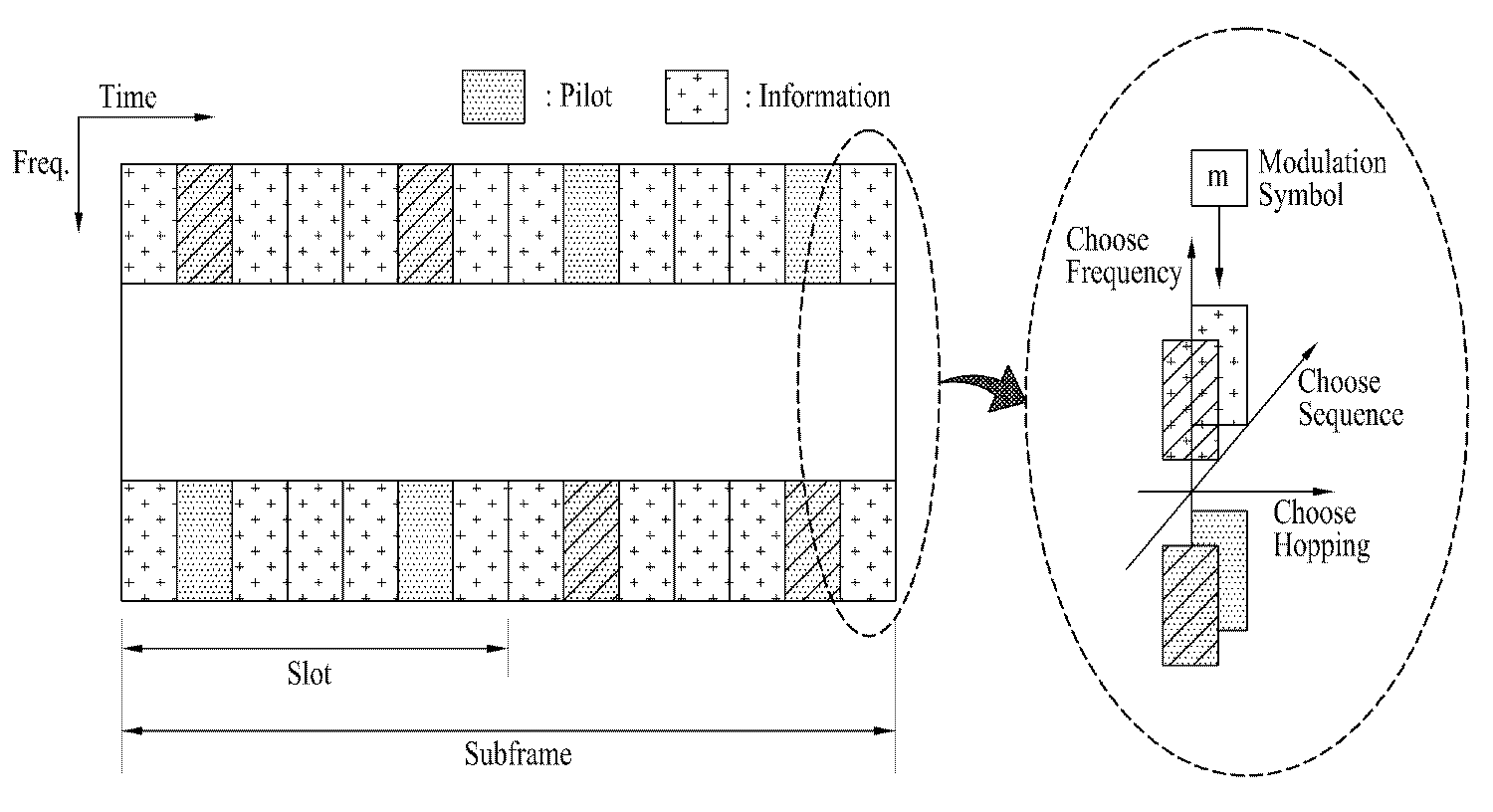
도 6은 상향링크 제어채널의 심볼 공간을 확장하는 예를 나타내는 도면이다. 도 6을 참조하면, 정보 전송을 위한 심볼 공간은 변조 차원, 시퀀스 차원, 주파수 차원, 호핑(Hopping) 차원 또는 이들의 조합을 이용하여 확장될 수 있다. 즉, 심볼 자체를 나타내는 변조된 신호와 상기 신호가 실려가는 시퀀스, 및 상기 신호를 전송하는 부반송파로 공간을 확장하는 것이 가능하다.6 is a diagram illustrating an example of extending the symbol space of an uplink control channel. Referring to FIG. 6, a symbol space for information transmission may be extended using a modulation dimension, a sequence dimension, a frequency dimension, a hopping dimension, or a combination thereof. That is, it is possible to expand the space with a modulated signal representing the symbol itself, a sequence carried by the signal, and a subcarrier transmitting the signal.
변조 차원은 PSK 및 회전된-PSK, QAM, 회전된-QAM, 가우스 최소 편이 변조(GMSK) 등을 포함할 수 있다. 보다 구체적으로, 변조 공간은 BPSK, 회전된-BPSK, QPSK, 회전된-QPSK, 16PSK, 회전된-16PSK, 16QAM, 64QAM, 또는 이들의 조합에 따른 중첩 변조 등을 포함한다. 심볼 공간을 확장하는 측면에서, 변조 공간은 QPSK, 8PSK, 16QAM 처럼 성상 개수를 늘려가는 방향으로 확장될 수 있다.The modulation dimension may include PSK and rotated-PSK, QAM, rotated-QAM, Gaussian minimum shift keying (GMSK), and the like. More specifically, the modulation space includes superposition modulation according to BPSK, rotated-BPSK, QPSK, rotated -QPSK, 16PSK, rotated -16PSK, 16QAM, 64QAM, or a combination thereof. In terms of extending the symbol space, the modulation space can be expanded in the direction of increasing the number of constellations, such as QPSK, 8PSK, and 16QAM.
시퀀스 차원을 이용하는 경우, 단말은 동일한 정보에 대해 사용되는 시퀀스를 다르게 선택함으로써, 전송 정보에 변화를 줄 수 있다. 예를 들어, '1'을 보낼 때는 미리 정해진 하나의 시퀀스를 사용해서 변조된 심볼을 전송하고, '0'을 보낼 때는 미리 정해진 다른 하나의 시퀀스를 사용해서 변조된 심볼을 전송하는 형태이다. 더 많은 비트 정보를 시퀀스 선택에 부가할 경우 더 많은 시퀀스를 묶어서 사용할 수 있다. 시퀀스 공간은 직교 시퀀스인 ZC(Zadoff-Chu), CAZAC(Constant amplitude zero autocorrelation waveform), 왈쉬(walsh), DFT(discrete fourier transform) 시퀀스 등을 포함할 수 있다. 또한, 시퀀스 공간은 의사-직교(quasi-orthogonal) 시퀀스, 상호상관 특성이 작은 PN(pseudo noise) 계열의 시퀀스를 포함할 수 있다. 상술한 방법에서는 시퀀스 차원을 심볼 공간의 확장에 사용하기 때문에, 하나의 제어채널을 통해 동시에 전송될 수 있는 단말의 수가 줄어들 수 있다. 그러나, 셀 내에서 단말의 수가 작은 경우(예, 펨토 셀)에는 시퀀스를 심볼 공간에 사용하더라도 무리는 없다.In the case of using the sequence dimension, the terminal can change the transmission information by selecting a different sequence for the same information. For example, when transmitting '1', a modulated symbol is transmitted using a predetermined sequence, and when '0' is transmitted, a modulated symbol is transmitted using another predetermined sequence. If more bit information is added to the sequence selection, more sequences can be used together. The sequence space may include orthogonal sequences ZC (Zadoff-Chu), CAZAC (Constant amplitude zero autocorrelation waveform), Walsh, and discrete fourier transform (DFT) sequences. In addition, the sequence space may include a quasi-orthogonal sequence and a PN (pseudo noise) sequence having a small cross-correlation characteristic. In the above method, since the sequence dimension is used to expand the symbol space, the number of terminals that can be simultaneously transmitted through one control channel can be reduced. However, in a case where the number of terminals in a cell is small (e.g., femtocell), a sequence may be used for a symbol space.
심볼 공간을 확장하는 또 다른 방법은 주파수 차원을 포함하는 것이다. 즉, 심볼 공간을 확장하는 것은 주파수 자원의 사용에 대한 응용을 포함한다. 주파수 축으로 제어채널이 여러 곳에 존재한다고 가정하면, 동일 신호에 대해 서로 다른 주파수 자원(즉, 서로 다른 서브밴드/채널)을 사용할 수 있다. 즉, 주파수 영역에서 신호가 전송되는 위치(서브밴드/채널)에 따라 추가 비트 정보를 정의할 수 있다. 시간 축으로 심볼 영역을 확장하는 것은 서로 다른 호핑 패턴의 사용을 포함한 다. 예를 들어, 신호를 전송함에 있어서 추가하고자 하는 비트 수가 적다면, 변조 심볼이 실리는 위치를 OFDM 심볼 마다 일정한 규칙으로 호핑시켜 전송할 수 있다. 패턴 규칙 자체가 비트 정보를 나타내므로, 전송 정보의 호핑이 완료되기 이전에는 해당 호핑 패턴이 나타내는 비트 정보를 알 수 없다. 따라서, 넓은 구간의 SC-FDMA 심볼을 이용하는 경우보다 좁은 구간의 SC-FDMA 심볼을 이용하는 것이 정보를 신속히 디코딩하는데 유리할 수 있다. 즉, 많은 양의 정보를 전송하는 경우보다 적은 양의 정보를 전송하는데 유리할 수 있다. 만일, 넓은 구간의 OFDM 심볼을 이용하여 호핑한다면, 호핑 패턴 자체가 정보의 LSB(least sigficant bit)를 지시하게 함으로써 디코딩 성능을 열화시키지 않을 수 있다.Another way to extend the symbol space is to include the frequency dimension. That is, extending the symbol space includes applications for the use of frequency resources. Assuming that the control channel exists in several places on the frequency axis, different frequency resources (i.e., different subbands / channels) may be used for the same signal. That is, additional bit information can be defined according to the position (subband / channel) where the signal is transmitted in the frequency domain. Extending the symbol region on the time axis involves the use of different hopping patterns. For example, if the number of bits to be added is small in transmitting a signal, the position where the modulation symbol is placed may be hopped by a predetermined rule for each OFDM symbol. Since the pattern rule itself represents bit information, the bit information indicated by the corresponding hopping pattern can not be known before hopping of the transmission information is completed. Therefore, using a SC-FDMA symbol of a narrower interval than the case of using a wide-interval SC-FDMA symbol may be advantageous for rapidly decoding information. That is, it may be advantageous to transmit a smaller amount of information than when a large amount of information is transmitted. If hopping is performed using a wide-area OFDM symbol, the hopping pattern itself may indicate the least significant bit (LSB) of information so as not to deteriorate decoding performance.
상술한 부가 공간들은 하나 이상의 조합으로 확장 가능하다. 또한, 다중 반송파가 가능한 경우, 주파수 자원의 사용에 대한 응용은 다중 반송파에서 특정 반송파를 선택하는 형태를 포함할 수 있다.The above-described additional spaces can be expanded in one or more combinations. Also, where multi-carrier is possible, the application for use of frequency resources may include a form of selecting a specific carrier on a multi-carrier.
3) 3) 감소된Reduced 파일럿( pilot( ReducedReduced pilotpilot ))
채널이 상대적으로 좋은 환경(예, 도플러 주파수, 주파수 오프셋이 작은 환경)에서는 많은 수의 파일럿이 필요하지 않다. 특히, 펨토 셀과 같이 기지국의 용량(capacity)이 단말보다 좋지 않을 수 있는 환경에서는 더욱 더 단말에게 유리한 파일럿 구조를 사용할 수 있다. 또한, 셀 내에 존재하는 단말의 개수가 많지 않은 경우에 파일럿의 필요성은 더욱 감소한다.A large number of pilots are not needed in a relatively good channel environment (eg, Doppler frequency, low frequency offset). In particular, in an environment such as a femtocell where the capacity of the base station may be worse than the terminal, the pilot structure advantageous to the terminal can be further used. Further, the need for pilots is further reduced when the number of terminals existing in the cell is not large.
도 7은 본 발명의 일 실시예에 따라 상향링크 제어채널에 변형된 파일럿을 할당하는 예를 나타낸다. 도 7을 참조하면, 하나의 슬롯에 포함되는 7개의 SC-FDMA 심볼 중에서 정 가운데 있는 SC-FDMA 심볼에는 파일럿(RS)이 실리고, 나머지 6개의 SC-FDMA 심볼에는 CQI 정보가 실린다. 펨토 셀과 같이 단말의 고속 이동이 제한되는 경우에는 한 슬롯 안에 한 개의 파일럿만 있더라도 무리가 없다. 파일럿이 할당되는 SC-FDMA 심볼의 위치는 예시적인 것으로서, 파일럿은 제어채널 상에서 배치가 용이한 곳에 배치될 수 있다.7 illustrates an example of allocating a modified pilot to an uplink control channel according to an embodiment of the present invention. Referring to FIG. 7, among the seven SC-FDMA symbols included in one slot, a pilot (RS) is inserted in an SC-FDMA symbol in the middle, and CQI information is inserted in the remaining six SC-FDMA symbols. In the case where the high-speed movement of the UE is limited like a femtocell, there is no problem even if there is only one pilot in one slot. The location of the SC-FDMA symbol to which the pilot is assigned is exemplary, and the pilot may be located where it is easy to place on the control channel.
각 단말은 직교 시퀀스(예, cyclic shift version of one root sequence)를 사용하여 구분된다. CQI 정보 심볼들은 SC-FDMA 심볼 전체에 변조되어 전달되고, 각각의 SC-FDMA 심볼은 하나의 시퀀스로 구성되어 있다. 상기 시퀀스는 주파수 영역 확산 부호이고, 직교 시퀀스, 의사-직교 시퀀스 또는 상관 특성이 우수한 다른 시퀀스를 포함할 수 있다.Each terminal is identified using an orthogonal sequence (e.g., a cyclic shift version of one root sequence). CQI information symbols are modulated and transmitted over the entire SC-FDMA symbol, and each SC-FDMA symbol is composed of one sequence. The sequence is a frequency domain spreading code and may include an orthogonal sequence, a pseudo-orthogonal sequence, or other sequences having good correlation properties.
도 7에서와 같이, 파일럿 구조를 변형할 경우, 기존에 파일럿을 할당했던 SC-FDMA 심볼에 CQI 정보를 실을 수 있다. 따라서, 한 서브프레임에서 전송할 수 있는 CQI 정보 심볼의 수는 2개로 늘어나고, QPSK 맵핑을 사용하는 경우 최대 4비트의 정보를 추가로 전송할 수 있게 된다.As shown in FIG. 7, when the pilot structure is modified, the CQI information can be stored in the SC-FDMA symbol to which the pilot has been allocated. Therefore, the number of CQI information symbols that can be transmitted in one subframe is increased to two, and when QPSK mapping is used, a maximum of 4 bits of information can be further transmitted.
도 8은 본 발명의 일 실시예에 따라 변형된 파일럿의 구조를 나타낸다.8 shows a structure of a modified pilot according to an embodiment of the present invention.
도 8을 참조하면, 파일럿이 슬롯 당 두개에서 하나로 줄어든 구조를 보여주고 있다. 이렇게 하더라도 펨토 셀과 같은 환경에서는 채널추정에 미치는 영향이 미미할 것이다. 이러한 구조로 사용함으로써, 펨토 셀 내의 단말은 슬롯 당 하나의 SC-FDMA 심볼을 CQI 또는 다른 제어정보를 전달하는데 사용할 수 있다.Referring to FIG. 8, there is shown a structure in which pilots are reduced from two to one per slot. Even in such a case, the effect on channel estimation will be insignificant in a femtocell-like environment. By using this structure, a UE in a femtocell can use one SC-FDMA symbol per slot to transmit CQI or other control information.
도 9는 본 발명의 일 실시예에 따라 변형된 파일럿의 다른 구조를 나타낸다.9 shows another structure of a modified pilot according to an embodiment of the present invention.
도 9를 참조하면, 단말은 서브프레임 내에서 하나의 SC-FDMA 심볼을 모두 사용하여 파일럿을 전송한다. 이와 같이, 모든 단말이 공통으로 사용하는 파일럿 채널을 만드는 것에 대해 고려할 수 있다. 펨토 셀과 같은 환경에서는 채널이 급격히 변하는 경우가 없기 때문에, 모든 대역에 대해서 단말은 한번만 파일럿을 전송하는 구조를 가질 수 있다. 즉, 하나의 TTI에 하나의 파이럿 심볼만이 존재하며, 펨토 셀 내의 단말들은 자신의 파일럿을 해당 위치에 전송하는 구조이다. 이 경우, 제어채널을 사용하는 단말 및 공유채널(즉, 데이터/제어 코드워드를 전송하는 대역)을 사용하는 단말은 모두 공통적인 파일럿 채널을 사용하게 된다. 상술한 구조를 사용함으로써, 펨토 셀의 채널 특징, 펨토 셀에서의 단말/기지국의 역대칭(즉, 단말의 전력 증폭기(Power AMP)가 기지국 보다 좋음) 전력을 활용할 수 있다. 또한, 상술한 구조를 사용함으로써, 보다 많은 제어채널 또는 데이터를 전송하기 위한 심볼 공간을 생성할 수 있다.Referring to FIG. 9, a UE transmits a pilot using all SC-FDMA symbols in a subframe. In this way, it can be considered to create a pilot channel commonly used by all terminals. In an environment such as a femtocell, since the channel does not change abruptly, the terminal can have a structure for transmitting the pilot only once for all bands. That is, there is only one pilot symbol in one TTI, and the terminals in the femtocell transmit their pilots to the corresponding positions. In this case, the terminal using the control channel and the terminal using the shared channel (i.e., the band for transmitting the data / control codeword) all use a common pilot channel. By using the above-described structure, it is possible to utilize the channel characteristics of the femtocell and the reverse symmetry of the terminal / base station in the femtocell (that is, the power amplifier of the terminal is better than the base station) power. Further, by using the above-described structure, a symbol space for transmitting more control channels or data can be generated.
위와 같은 구성에서, 해당 펨토 셀이 사용하는 대역에 걸친 파일럿의 구조는 크기가 조절될 수 있어야(scalable)하는 제한을 갖는다. 예를 들어, 1 RB 크기의 제어채널을 사용하는 단말이 존재할 수 있으므로, 수신단에서는 성능감소가 적은 파일럿 구조를 사용해야 할 것이다. 일 예로, RB 단위로 파일럿 시퀀스를 생성하고 커버 시퀀스를 사용함으로써, PAPR/CM (Peak-to-Average Power Ratio/cubic metric) 특징에서 많은 손해를 보지 않고 파일럿 시퀀스를 생성할 수 있다. 도 9에서, 파일럿의 위치 및 개수는 예시적인 것으로서, 파일럿은 제어채널 상에서 배치가 용이한 곳에 배치될 수 있다. 또한, 한 서브프레임 내에 복수의 파일럿이 존재 할 수도 있고, 여러 서브프레임 당 파일럿이 하나만 존재하는 경우도 가능하다.In the above configuration, the structure of the pilot over the band used by the femtocell has a limitation that the size must be scalable. For example, a terminal using a 1-RB-sized control channel may exist, and therefore, a pilot structure with less performance degradation should be used at the receiving end. For example, by generating a pilot sequence on an RB basis and using a cover sequence, a pilot sequence can be generated without much loss in the PAPR / CM (Peak-to-Average Power Ratio / Cubic metric) feature. In FIG. 9, the location and number of pilots are exemplary, and the pilots can be placed where placement is easy on the control channel. Also, there may be a plurality of pilots in one subframe, or there may be only one pilot in each subframe.
도 10은 본 발명의 일 실시예에 따라 변형된 파일럿의 또 다른 구조를 나타낸다. 펨토 셀과 같은 환경에서, 단말은 전력 증폭기(PA)에 여지가 많기 때문에, PAPR/CM은 실제로 큰 문제가 되지 않는다. 더구나, 도 9에서와 같이, 하나의 SC-FDMA 심볼을 완전히 다 차지하는 형태의 파일럿 구성은 설계상 문제점을 만들 수 있다. 따라서, 약간의 PAPR/CM 불리를 안더라도, 해당 제어채널 내에서만 신호를 전송하는 구조를 사용하는 것이 바람직할 수 있다. 이를 위해서, 제어채널에 대해 호핑(hopping)을 제한할 수 있다. AWGN과 비슷한 플랫 페이딩(flat fading)이 나타나는 환경에서 슬롯 호핑(slot hopping)이 주는 이득은 미미하다. 따라서, 도 10에 예시한 바와 같이, 슬롯 호핑을 배제함으로써, 한 서브프레임 내에서 제어채널이 연속으로 보이도록 변형할 수 있다. 이런 구조는 기존 제어채널 구조와 완벽히 호환되면서도 CQI 심볼 공간이 확장된다. 도 10에서, 파일럿의 위치 및 개수는 예시적인 것으로서, 파일럿은 제어채널 상에서 배치가 용이한 곳에 배치될 수 있다. 또한, 한 서브프레임 내에 복수의 파일럿이 존재할 수도 있고, 여러 서브프레임 당 파일럿이 하나만 존재하는 경우도 가능하다.Figure 10 shows another structure of a modified pilot according to an embodiment of the present invention. In an environment such as a femtocell, the PAPR / CM is not really a big problem because the terminal has a lot of power amplifier (PA). Moreover, as shown in FIG. 9, a pilot configuration in which one SC-FDMA symbol is completely occupied can cause design problems. Therefore, even if there is little PAPR / CM disadvantage, it may be desirable to use a structure that transmits signals only within the control channel. To this end, it is possible to limit hopping to the control channel. In an environment where flat fading is similar to AWGN, the gain of slot hopping is negligible. Therefore, as illustrated in Fig. 10, by excluding slot hopping, the control channel can be deformed so as to be continuously viewed in one subframe. This structure is fully compatible with the existing control channel structure and also extends the CQI symbol space. In Fig. 10, the location and number of pilots are exemplary, and the pilots can be placed where placement is easy on the control channel. Also, there may be a plurality of pilots within one subframe, or there may be only one pilot per several subframes.
4) 다중 안테나 확장(4) Multiple antenna extension ( MultipleMultiple antennaantenna extensionextension ))
단말이 다중 안테나 전송 능력을 갖고 있는 경우(즉, 전송 RF 체인/전력 증폭기가 여러 개 존재), 상기 능력을 이용하여 상향링크 제어채널을 전송함으로써 보다 효율적으로 수신단의 QoS를 보장하고, 공간 효율(spectral efficiency)을 높일 수 있다. 특히, 안테나 개수의 증가에 따라 전송해야 되는 CQI 정보량이 많아지 는 경우, 다중 안테나 전송 능력은 심볼 공간의 확장에 있어서 필수적이다. 다만, CQI 정보 심볼들은 SC-FDMA 심볼 전체에 변조되어 전달되고, SC-FDMA 심볼은 하나의 시퀀스로 구성되어 있다는 점에서 일반적인 다중 안테나 기술과는 다른 접근 방법이 필요하다. 이하, 기존 SC-FDMA의 단일 반송파 전송 특성을 깨지 않고, 다중 안테나로 신호를 전송하는 방법에 대해 구체적으로 설명하도록 한다.When the UE has multi-antenna transmission capability (that is, there are a plurality of transmission RF chains / power amplifiers), by transmitting the uplink control channel using the capability, the QoS of the receiver can be more efficiently guaranteed, spectral efficiency can be increased. In particular, if the amount of CQI information to be transmitted increases as the number of antennas increases, the multi-antenna transmission capability is essential for the extension of the symbol space. However, the CQI information symbols are modulated and transmitted over the entire SC-FDMA symbol, and an SC-FDMA symbol is composed of one sequence. Therefore, an approach different from the general multi-antenna technique is needed. Hereinafter, a method of transmitting a signal to multiple antennas without breaking the single carrier transmission characteristic of the existing SC-FDMA will be described in detail.
도 11에 본 발명의 일 실시예에 따라 다중 안테나를 통해 상향링크 제어채널을 전송하는 경우에, 서로 다른 안테나를 통해 서로 다른 전송 자원(예, 서로 다른 제어채널)에 신호를 전송하는 예를 나타냈다. 이 경우, 전송 포맷은 단일 전송 안테나에서 사용했던 포맷을 그대로 사용할 수 있다. 이 경우, 전송 신호에 안테나 셀렉션(selection)을 적용할 수 있다. 안테나 셀렉션은 신호가 전송되는 안테나가 특정 간격으로 변경되는 것을 의미한다. 즉, 모든 안테나에서 신호를 전송하지만, 각각의 안테나에서 전송되는 신호는 소정 조건하에서 서로서로 바뀔 수 있다. 안테나 셀렉션은 전송되는 신호에 대해 슬롯 단위로 적용될 수 있다. 또한, 각각의 안테나를 통해 전송되는 신호는 성상이 변형될 수도 있다. 즉, 각각의 안테나를 통해 전송되는 신호에 콘쥬케이트(conjugate)와 같은 연산을 적용할 수 있다. 또한, CQI 정보를 전송하기 위한 심볼 공간에 대한 요구(requirement)가 적은 경우에는 여러 개의 전송 안테나를 임의 개수로 짝지움으로써 전송 다이버시티 구조를 만들 수 있다. 전송 다이버시티를 위한 기법은 STBC(space time block code) 기법, SFBC(space frequency block code) 등을 포함한다. 이 경우, 전송 다이버시티를 위한 연산은 시퀀스 자체, 심볼 자체 또는 시퀀스/심볼 모두에 적용될 수 있다. 11 illustrates an example of transmitting a signal to different transmission resources (e.g., different control channels) through different antennas when transmitting an uplink control channel through multiple antennas according to an embodiment of the present invention . In this case, the transmission format can use the same format as that used in the single transmission antenna. In this case, an antenna selection can be applied to the transmission signal. An antenna selection means that the antenna through which the signal is transmitted is changed at a certain interval. That is, although signals are transmitted from all the antennas, the signals transmitted from the respective antennas may be mutually exchanged under a predetermined condition. The antenna selection may be applied slot by slot for the transmitted signal. In addition, signals transmitted through the respective antennas may be changed in properties. That is, an operation such as a conjugate may be applied to a signal transmitted through each antenna. In addition, when the requirement for the symbol space for transmitting the CQI information is small, a transmission diversity structure can be formed by mating a plurality of transmission antennas in an arbitrary number. Techniques for transmit diversity include a space time block code (STBC) technique and a space frequency block code (SFBC) technique. In this case, the operation for transmit diversity may be applied to the sequence itself, the symbol itself, or both sequences / symbols.
상술한 방법은 기존 단말들과 호환성을 철저하게 유지하는 반면, 더 많은 전송 자원을 사용하는 단점을 가지고 있다.The above method has the disadvantage of using more transmission resources while maintaining compatibility with existing terminals.
도 12는 본 발명의 일 실시예에 따라 다중 안테나를 통해 상향링크 제어채널을 전송하는 경우에, 각 안테나가 동일한 전송 자원에 신호를 전송하는 예를 나타낸다. 이 경우, 안테나가 여러 개 있으므로, 전송 다이버시티를 얻거나, 공간 멀티플렉싱을 얻는 기법을 적용할 수 있다.12 illustrates an example in which each antenna transmits a signal to the same transmission resource when an uplink control channel is transmitted through multiple antennas according to an embodiment of the present invention. In this case, since there are a plurality of antennas, a technique of obtaining transmission diversity or obtaining spatial multiplexing can be applied.
전송 다이버시티는 다중 안테나를 통해 동일한 신호를 전송하는 경우에 얻을 수 있다. 즉, 단말은 수신단이 각 안테나 신호를 구분할 수 없는 형태로 신호를 전송하게 된다. 다만, 단말의 전송 안테나는 매우 가까이 배치되어 있기 때문에 각각의 채널을 통해 수신단의 수신 안테나로 전달되는 전력-지연 프로파일(power-delay profile)은 매우 유사하게 나타난다. 이들 신호의 채널 페이즈(channel phase)가 상쇄적인 빔(destructive beam)을 형성하는 경우, 수신단은 다이버시티 이득을 얻을 수 없게 된다. 따라서, 동일한 자원을 이용하여 상향링크 제어채널을 전송하는 경우 제어채널 신호에 빔포밍(beamforming)이 생기지 않도록 주의해야 한다.Transmit diversity can be obtained when transmitting the same signal through multiple antennas. That is, the terminal transmits a signal in a form in which the receiving terminal can not distinguish each antenna signal. However, since the transmit antennas of the UE are located very close to each other, the power-delay profiles transmitted to the receive antennas of the receive channels through the respective channels are very similar. When the channel phase of these signals forms a destructive beam, the receiving end can not obtain the diversity gain. Therefore, care must be taken not to cause beamforming in the control channel signal when the uplink control channel is transmitted using the same resource.
상향링크 제어채널 간에 빔포밍을 감소시키기 위해, 아주 작은 사이클릭 딜레이(cyclic delay)을 삽입하는 방식을 생각할 수 있다. 즉, 상향링크 제어채널에 전송 안테나 별로 약간의 서로 다른 사이클릭 딜레이를 도입함으로써, 수신단에서 전력-피크(power-peak) 끼리 중첩되지 않도록 할 수 있다.In order to reduce the beamforming between the uplink control channels, a method of inserting a very small cyclic delay may be considered. That is, by introducing slightly different cyclic delays for each transmission antenna in the uplink control channel, it is possible to prevent the power-peaks from overlapping at the receiving end.
송신-수신 안테나 쌍에 대한 채널 추정이 가능한 경우 좀 더 다양한 다이버시티 또는 공간 멀티플렉싱이 가능하다. 이를 위해, 각 안테나는 독립적인 채널 추 정이 가능해야 하며, 다중 파일럿 심볼 구조를 이용할 수 있다.More diversity or spatial multiplexing is possible if channel estimation for transmit-receive antenna pairs is possible. To do this, each antenna must be capable of independent channel estimation and can use a multiple pilot symbol structure.
도 13은 본 발명의 일 실시예에 따라 다중 안테나를 통해 상향링크 제어채널을 전송하는 경우에, 각 안테나의 파일럿 심볼을 구별하기 위한 방법을 예시한다. 도 13을 참조하면, 한 슬롯안에 존재하는 복수의 파일럿 심볼은 서로 다른 시퀀스를 이용하는 구별될 수 있다. 시퀀스를 이용하는 방법에 대해서는 뒤에서 다시 설명한다. 이 외에, 각각의 SC-FDMA 심볼을 서로 다른 안테나에 할당하거나, SC-FDMA 심볼의 조합을 안테나 세트에 적용하는 형태로 파일럿 심볼을 할당할 수 있다.FIG. 13 illustrates a method for distinguishing pilot symbols of each antenna when an uplink control channel is transmitted through multiple antennas according to an embodiment of the present invention. Referring to FIG. 13, a plurality of pilot symbols existing in one slot can be distinguished by using different sequences. The method of using the sequence will be described later. Besides, it is possible to allocate each SC-FDMA symbol to different antennas, or allocate a pilot symbol in such a manner that a combination of SC-FDMA symbols is applied to an antenna set.
또한, 안테나의 개수가 많은 경우에는 각각의 안테나를 적절히 짝지워서 동일한 자원을 공유하게 할 수 있다. 이 경우, 짝지워진 안테나들의 파일럿은 시퀀스를 이용하여 구분될 수 있다. 파일럿만 구분될 수 있으면 관련된 제어정보를 추출하여 복조하는 가능하므로, 시퀀스는 파일럿에만 적용해도 충분하다. 시퀀스에 의해 구분할 수 있는 파일럿의 개수는 시퀀스 길이에 따라 달라진다. 또한, 시퀀스 길이는 슬롯에 있는 파일럿 심볼의 개수에 의해 제한된다. 예를 들어, 한 슬롯에 파일럿 심볼의 개수가 3이라면 시퀀스 길이는 3으로 제한된다. 이 경우, 시퀀스로 구분할 수 있는 파일럿이 3개이므로, 함께 짝지울 수 있는 안테나도 3개가 된다. 만약, 슬롯 당 호핑이 제한된다면, 시퀀스 길이는 서브프레임에 있는 파일럿 심볼의 개수에 의해 제한된다. 상기 시퀀스는 직교 시퀀스인 ZC(Zadoff-Chu), CAZAC(Constant amplitude zero autocorrelation waveform), 왈쉬(walsh), DFT(discrete fourier transform) 시퀀스 등을 포함할 수 있다. 또한, 시퀀스 공간은 의사-직교(quasi-orthogonal) 시퀀스, 상호상관 특성이 작은 PN(pseudo noise) 계열의 시퀀스를 포함할 수 있다.Further, when the number of antennas is large, each antenna can be properly paired to share the same resources. In this case, the pilots of the mapped antennas may be separated using a sequence. If only pilots can be distinguished, it is possible to extract and demodulate the associated control information, so that the sequence may be applied only to pilots. The number of pilots that can be distinguished by the sequence depends on the sequence length. Also, the sequence length is limited by the number of pilot symbols in the slot. For example, if the number of pilot symbols in one slot is 3, the sequence length is limited to 3. In this case, since there are three pilots that can be classified into sequences, three antennas that can be mated together are also three. If hopping per slot is restricted, the sequence length is limited by the number of pilot symbols in the subframe. The sequence may include orthogonal sequences ZC (Zadoff-Chu), CAZAC (Constant amplitude zero autocorrelation waveform), Walsh, and discrete fourier transform (DFT) sequences. In addition, the sequence space may include a quasi-orthogonal sequence and a PN (pseudo noise) sequence having a small cross-correlation characteristic.
구체적으로, 3GPP LTE의 CQI를 위한 상향링크 슬롯 구조는 5개의 CQI 정보 심볼과 2개의 파일럿 심볼로 구성되어 있고, 슬롯 당 호핑이 적용된다(도 5). 슬롯 당 2개의 파일럿 심볼이 있으므로 사용할 수 있는 시퀀스는 길이가 2이다. 따라서, 2개의 안테나(또는 묶음)를 서로 구분될 수 있다. 이 경우, 심볼 공간은 최대 5*2 = 10의 공간으로 확장된다. 만약, 구분될 수 있는 파일럿의 개수를 증가시키려면 한 슬롯에 포함되는 파일럿 심볼의 개수를 증가시켜야 한다. 도 13을 참조하면, 한 슬롯이 4개의 데이터 심볼과 3개의 파일럿 심볼로 구성되어 있다. 파일럿 심볼의 개수가 3이므로, 길이가 3인 시퀀스를 적용할 수 있다. 예를 들어, 길이가 3인 시퀀스는 {(1, 1, 1), (1, ej2 π/3, ej4 π/3), (1, ej4 π/3, ej2 π/3)}을 포함할 수 있다. 따라서, 3개의 안테나(또는 묶음)가 서로 구분될 수 있다. 이 경우, 심볼 공간은 최대 4*3 = 12의 공간으로 확장된다. 이와 같이 안테나 수의 증가에 따라 심볼 공간을 늘릴 수 있다면 파일럿을 추가로 할당하는 것도 가능하다. 또한, 이러한 심볼 공간은 전송해야 할 정보가 많지 않은 경우에 다이버시티 용도로 활용할 수 있다. 즉, 각 안테나에서 전송하는 신호를 STBC 또는 SFBC 형식으로 변환하여 전송할 수 있다. 이 경우, 변환 대상은 변조 심볼 및 시퀀스 신호 자체 중에서 적어도 하나를 포함한 구조를 가질 수 있다.Specifically, an uplink slot structure for CQI of 3GPP LTE is composed of five CQI information symbols and two pilot symbols, and hopping per slot is applied (FIG. 5). Since there are two pilot symbols per slot, the available sequence is 2 in length. Therefore, two antennas (or bundles) can be distinguished from each other. In this case, the symbol space is extended to a space of at most 5 * 2 = 10. If the number of pilots that can be distinguished is increased, the number of pilot symbols included in one slot should be increased. Referring to FIG. 13, one slot is composed of four data symbols and three pilot symbols. Since the number of pilot symbols is 3, a sequence of
이상에서 설명된 실시예들은 본 발명의 구성요소들과 특징들이 소정 형태로 결합된 것들이다. 각 구성요소 또는 특징은 별도의 명시적 언급이 없는 한 선택적 인 것으로 고려되어야 한다. 각 구성요소 또는 특징은 다른 구성요소나 특징과 결합되지 않은 형태로 실시될 수 있다. 또한, 일부 구성요소들 및/또는 특징들을 결합하여 본 발명의 실시예를 구성하는 것도 가능하다. 본 발명의 실시예들에서 설명되는 동작들의 순서는 변경될 수 있다. 어느 실시예의 일부 구성이나 특징은 다른 실시예에 포함될 수 있고, 또는 다른 실시예의 대응하는 구성 또는 특징과 교체될 수 있다. 특허청구범위에서 명시적인 인용 관계가 있지 않은 청구항들을 결합하여 실시예를 구성하거나 출원 후의 보정에 의해 새로운 청구항으로 포함시킬 수 있음은 자명하다.The embodiments described above are those in which the elements and features of the present invention are combined in a predetermined form. Each element or feature shall be considered optional unless otherwise expressly stated. Each component or feature may be implemented in a form that is not combined with other components or features. It is also possible to construct embodiments of the present invention by combining some of the elements and / or features. The order of the operations described in the embodiments of the present invention may be changed. Some configurations or features of certain embodiments may be included in other embodiments, or may be replaced with corresponding configurations or features of other embodiments. It is clear that the claims that are not expressly cited in the claims may be combined to form an embodiment or be included in a new claim by an amendment after the application.
본 문서에서 본 발명의 실시예들은 주로 단말과 기지국 간의 데이터 송수신 관계를 중심으로 설명되었다. 본 문서에서 기지국에 의해 수행된다고 설명된 특정 동작은 경우에 따라서는 그 상위 노드(upper node)에 의해 수행될 수 있다. 즉, 기지국을 포함하는 복수의 네트워크 노드들(network nodes)로 이루어지는 네트워크에서 단말과의 통신을 위해 수행되는 다양한 동작들은 기지국 또는 기지국 이외의 다른 네트워크 노드들에 의해 수행될 수 있음은 자명하다. '기지국'은 고정국(fixed station), Node B, eNode B(eNB), 억세스 포인트(access point) 등의 용어에 의해 대체될 수 있다. 또한, '단말'은 UE(User Equipment), MS(Mobile Station), MSS(Mobile Subscriber Station) 등의 용어로 대체될 수 있다.In this document, the embodiments of the present invention have been mainly described with reference to the data transmission / reception relationship between the terminal and the base station. The specific operation described herein as being performed by the base station may be performed by its upper node, in some cases. That is, it is apparent that various operations performed for communication with a terminal in a network including a plurality of network nodes including a base station can be performed by a network node other than the base station or the base station. A 'base station' may be replaced by terms such as a fixed station, a Node B, an eNode B (eNB), an access point, and the like. The term 'terminal' may be replaced with terms such as User Equipment (UE), Mobile Station (MS), and Mobile Subscriber Station (MSS).
본 발명에 따른 실시예는 다양한 수단, 예를 들어, 하드웨어, 펌웨어(firmware), 소프트웨어 또는 그것들의 결합 등에 의해 구현될 수 있다. 하드웨어에 의한 구현의 경우, 본 발명의 일 실시예는 하나 또는 그 이상의 ASICs(application specific integrated circuits), DSPs(digital signal processors), DSPDs(digital signal processing devices), PLDs(programmable logic devices), FPGAs(field programmable gate arrays), 프로세서, 콘트롤러, 마이크로 콘트롤러, 마이크로 프로세서 등에 의해 구현될 수 있다.Embodiments in accordance with the present invention may be implemented by various means, for example, hardware, firmware, software, or a combination thereof. In the case of hardware implementation, an embodiment of the present invention may include one or more application specific integrated circuits (ASICs), digital signal processors (DSPs), digital signal processing devices (DSPDs), programmable logic devices (PLDs) field programmable gate arrays, processors, controllers, microcontrollers, microprocessors, and the like.
펌웨어나 소프트웨어에 의한 구현의 경우, 본 발명의 일 실시예는 이상에서 설명된 기능 또는 동작들을 수행하는 모듈, 절차, 함수 등의 형태로 구현될 수 있다. 소프트웨어 코드는 메모리 유닛에 저장되어 프로세서에 의해 구동될 수 있다. 상기 메모리 유닛은 상기 프로세서 내부 또는 외부에 위치하여, 이미 공지된 다양한 수단에 의해 상기 프로세서와 데이터를 주고 받을 수 있다.In the case of an implementation by firmware or software, an embodiment of the present invention may be implemented in the form of a module, a procedure, a function, or the like which performs the functions or operations described above. The software code can be stored in a memory unit and driven by the processor. The memory unit may be located inside or outside the processor, and may exchange data with the processor by various well-known means.
본 발명은 본 발명의 특징을 벗어나지 않는 범위에서 다른 특정한 형태로 구체화될 수 있음은 당업자에게 자명하다. 따라서, 상기의 상세한 설명은 모든 면에서 제한적으로 해석되어서는 아니되고 예시적인 것으로 고려되어야 한다. 본 발명의 범위는 첨부된 청구항의 합리적 해석에 의해 결정되어야 하고, 본 발명의 등가적 범위 내에서의 모든 변경은 본 발명의 범위에 포함된다.It will be apparent to those skilled in the art that the present invention may be embodied in other specific forms without departing from the spirit of the invention. Accordingly, the above description should not be construed in a limiting sense in all respects and should be considered illustrative. The scope of the present invention should be determined by rational interpretation of the appended claims, and all changes within the scope of equivalents of the present invention are included in the scope of the present invention.
본 발명은 무선 통신 시스템에 적용될 수 있다. 구체적으로, 본 발명은 무선 통신 시스템에서 제어채널을 상향링크 전송하는데 적용될 수 있다.The present invention can be applied to a wireless communication system. In particular, the present invention can be applied to uplink transmission of a control channel in a wireless communication system.
본 발명에 관한 이해를 돕기 위해 상세한 설명의 일부로 포함되는, 첨부 도면은 본 발명에 대한 실시예를 제공하고, 상세한 설명과 함께 본 발명의 기술적 사상을 설명한다.BRIEF DESCRIPTION OF THE DRAWINGS The accompanying drawings, which are included to provide a further understanding of the invention and are incorporated in and constitute a part of the specification, illustrate embodiments of the invention and, together with the description, serve to explain the principles of the invention.
도 1은 SC-FDMA 방식에 따른 송신기의 블록도를 예시한다.1 illustrates a block diagram of a transmitter according to the SC-FDMA scheme.
도 2는 무선 프레임의 구조를 예시한다.2 illustrates the structure of a radio frame.
도 3은 상향링크 슬롯에 대한 자원 그리드(resource grid)를 예시한다.FIG. 3 illustrates a resource grid for an uplink slot.
도 4는 상향링크 서브프레임의 구조를 예시한다.4 illustrates a structure of an uplink subframe.
도 5는 서브프레임상의 상향링크 제어채널로서 CQI 채널 구조를 예시한다.5 illustrates a CQI channel structure as an uplink control channel on a subframe.
도 6은 본 발명의 일 실시예에 따라 상향링크 제어채널의 심볼 공간을 확장하는 예이다.6 is an example of extending the symbol space of an uplink control channel according to an embodiment of the present invention.
도 7은 본 발명의 일 실시예에 따라 상향링크 제어채널에 변형된 파일럿을 할당하는 예를 나타낸다.7 illustrates an example of allocating a modified pilot to an uplink control channel according to an embodiment of the present invention.
도 8은 본 발명의 일 실시예에 따라 변형된 파일럿의 구조를 나타낸다.8 shows a structure of a modified pilot according to an embodiment of the present invention.
도 9는 본 발명의 일 실시예에 따라 변형된 파일럿의 다른 구조를 나타낸다.9 shows another structure of a modified pilot according to an embodiment of the present invention.
도 10은 본 발명의 일 실시예에 따라 변형된 파일럿의 또 다른 구조를 나타낸다.Figure 10 shows another structure of a modified pilot according to an embodiment of the present invention.
도 11은 본 발명의 일 실시예에 따라 다중 안테나를 통해 상향링크 제어채널을 전송하는 예이다.11 is an example of transmitting an uplink control channel through multiple antennas according to an embodiment of the present invention.
도 12는 본 발명의 일 실시예에 따라 다중 안테나를 통해 상향링크 제어채널 을 전송하는 다른 예이다.12 is another example of transmitting an uplink control channel through multiple antennas according to an embodiment of the present invention.
도 13은 본 발명의 일 실시예에 따라 다중 안테나를 통해 상향링크 제어채널을 전송하는 또 다른 예이다.13 is another example of transmitting an uplink control channel through multiple antennas according to an embodiment of the present invention.
Claims (15)
Priority Applications (2)
| Application Number | Priority Date | Filing Date | Title |
|---|---|---|---|
| PCT/KR2009/004469 WO2010018970A2 (en) | 2008-08-11 | 2009-08-11 | Method for uplink transmitting control information |
| US13/057,427 US8681697B2 (en) | 2008-08-11 | 2009-08-11 | Method for uplink transmitting control information |
Applications Claiming Priority (2)
| Application Number | Priority Date | Filing Date | Title |
|---|---|---|---|
| US8773708P | 2008-08-11 | 2008-08-11 | |
| US61/087,737 | 2008-08-11 |
Publications (2)
| Publication Number | Publication Date |
|---|---|
| KR20100019934A KR20100019934A (en) | 2010-02-19 |
| KR101597573B1 true KR101597573B1 (en) | 2016-02-25 |
Family
ID=42090131
Family Applications (1)
| Application Number | Title | Priority Date | Filing Date |
|---|---|---|---|
| KR1020090003311A Active KR101597573B1 (en) | 2008-08-11 | 2009-01-15 | Uplink transmission method of control information |
Country Status (3)
| Country | Link |
|---|---|
| US (1) | US8681697B2 (en) |
| KR (1) | KR101597573B1 (en) |
| WO (1) | WO2010018970A2 (en) |
Families Citing this family (39)
| Publication number | Priority date | Publication date | Assignee | Title |
|---|---|---|---|---|
| KR101387529B1 (en) * | 2007-10-15 | 2014-04-23 | 엘지전자 주식회사 | Method for communicating data between mobile station and base station, and Mobile communication terminal thereof |
| EP2509269B1 (en) * | 2008-09-19 | 2017-10-04 | Telefonaktiebolaget LM Ericsson (publ) | Signal transmission on mutiple component carriers in a telecommunication system |
| JP5219708B2 (en) * | 2008-09-22 | 2013-06-26 | 株式会社エヌ・ティ・ティ・ドコモ | Mobile terminal apparatus, radio base station apparatus, radio communication system, and radio communication method |
| US9608780B2 (en) * | 2008-09-23 | 2017-03-28 | Qualcomm Incorporated | Transmit diversity for SC-FDMA |
| EP2353249A1 (en) * | 2008-10-20 | 2011-08-10 | Nokia Siemens Networks Oy | Sounding channel apparatus and method |
| EP3404963B1 (en) * | 2009-01-30 | 2019-08-28 | Samsung Electronics Co., Ltd. | Transmitting uplink control information over a data channel or over a control channel |
| WO2010126339A2 (en) * | 2009-04-30 | 2010-11-04 | Samsung Electronics Co., Ltd. | Multiplexing large payloads of control information from user equipments |
| WO2010137925A2 (en) * | 2009-05-29 | 2010-12-02 | 엘지전자 주식회사 | Method and device for efficiently transmitting precoded reference signal in radio communication system |
| US10193678B2 (en) * | 2009-10-08 | 2019-01-29 | Qualcomm Incorporated | Muting schemes for channel state information reference signal and signaling thereof |
| KR101783610B1 (en) * | 2010-04-21 | 2017-10-10 | 엘지전자 주식회사 | Apparatus and method of transmitting control information in wireless communication system |
| KR101790523B1 (en) | 2010-04-22 | 2017-10-26 | 엘지전자 주식회사 | Apparatus and method of transmitting control information in wireless communication system |
| TW201210239A (en) * | 2010-05-06 | 2012-03-01 | Htc Corp | Method of multiplexing and transmission of uplink control information and related communication device |
| JP4923161B1 (en) | 2010-09-29 | 2012-04-25 | シャープ株式会社 | Mobile communication system, mobile station apparatus, base station apparatus, communication method, and integrated circuit |
| CN101958774B (en) * | 2010-09-30 | 2015-10-21 | 中兴通讯股份有限公司 | A kind of feedback information sending method and subscriber equipment |
| US9113457B2 (en) | 2010-10-01 | 2015-08-18 | Lg Electronics Inc. | Method and apparatus for transmitting control information |
| WO2012138112A2 (en) | 2011-04-04 | 2012-10-11 | 엘지전자 주식회사 | Method for transmitting uplink control information in a wireless communication system and device for same. |
| KR101487122B1 (en) | 2011-04-28 | 2015-01-28 | 엘지전자 주식회사 | Method and apparatus for transmitting uplink control information in a wireless communication system |
| WO2013022260A2 (en) * | 2011-08-07 | 2013-02-14 | 엘지전자 주식회사 | Method and user equipment for transmitting uplink control information |
| JP5893897B2 (en) | 2011-11-11 | 2016-03-23 | 株式会社Nttドコモ | User apparatus, base station apparatus, and wireless communication method |
| CN102523026B (en) * | 2011-12-20 | 2014-04-02 | 展讯通信(上海)有限公司 | Communication terminal, detection method for rank indication parameters of communication terminal and detection device for rank indication parameters of communication terminal |
| US9661612B2 (en) * | 2012-06-29 | 2017-05-23 | Samsung Electronics Co., Ltd. | Methods and apparatus for uplink control channel multiplexing in beamformed cellular systems |
| US9973980B2 (en) | 2013-03-06 | 2018-05-15 | Qualcomm Incorporated | Communications methods and apparatus that facilitate handover decisions and related measurements |
| US9094951B2 (en) | 2013-03-14 | 2015-07-28 | Qualcomm Incorporated | Communications methods and apparatus for allocation of resources and handover related measurements |
| KR102078191B1 (en) * | 2013-06-14 | 2020-02-17 | 삼성전자주식회사 | Method and apparatus for measiuring link quality in wireless communication system |
| KR102171502B1 (en) * | 2014-02-27 | 2020-10-29 | 삼성전자 주식회사 | Modulation method and apparatus for tranceiving signal in a mobile communication system |
| WO2016004634A1 (en) | 2014-07-11 | 2016-01-14 | Mediatek Singapore Pte. Ltd. | Method for enb, ue uplink transmission and reception |
| KR102406284B1 (en) * | 2014-11-11 | 2022-06-08 | 한국전자통신연구원 | Method and apparatus for mapping virtual antenna to physical antenna |
| US9806778B2 (en) * | 2014-11-11 | 2017-10-31 | Electronics And Telecommunications Research Institute | Method and apparatus for mapping virtual antenna to physical antenna |
| CN111884957B (en) | 2015-01-28 | 2023-05-16 | 索尼公司 | Wireless communication device and wireless communication method |
| WO2017071734A1 (en) * | 2015-10-27 | 2017-05-04 | Sony Mobile Communications, Inc. | Pilot resource allocation for a mimo system |
| US10980022B2 (en) * | 2015-12-04 | 2021-04-13 | Qualcomm Incorporated | Coupled mode common uplink burst in TDD subframe structure |
| US10448380B2 (en) * | 2016-06-27 | 2019-10-15 | Qualcomm Incorporated | Split symbol control for aligned numerology |
| US10038488B2 (en) | 2016-12-22 | 2018-07-31 | Qualcomm Incorporated | PUCCH transmit diversity with one-symbol STBC |
| US10454657B2 (en) | 2017-02-28 | 2019-10-22 | Qualcomm Incorporated | Narrowband time-division duplex frame structure for narrowband communications |
| WO2019012562A1 (en) * | 2017-07-14 | 2019-01-17 | Wisig Networks Private Limited | Systems and methods for transmitting control data in a communication network |
| US10965786B2 (en) | 2018-10-31 | 2021-03-30 | At&T Intellectual Property I, L.P. | Adaptive fixed point mapping for uplink and downlink fronthaul |
| CN111385076B (en) * | 2018-12-29 | 2021-08-13 | 华为技术有限公司 | Communication method, network device and terminal device |
| US11502790B2 (en) * | 2020-04-09 | 2022-11-15 | Qualcomm Incorporated | Orthogonal sequence generation for multi-bit payloads |
| CN112887230B (en) * | 2021-01-08 | 2021-11-19 | 西安电子科技大学 | Channel estimation method of space-time block coding MSK system under flat fading channel |
Family Cites Families (114)
| Publication number | Priority date | Publication date | Assignee | Title |
|---|---|---|---|---|
| US6141393A (en) | 1999-03-03 | 2000-10-31 | Motorola, Inc. | Method and device for channel estimation, equalization, and interference suppression |
| US20020110108A1 (en) | 2000-12-07 | 2002-08-15 | Younglok Kim | Simple block space time transmit diversity using multiple spreading codes |
| US20030048753A1 (en) | 2001-08-30 | 2003-03-13 | Ahmad Jalali | Method and apparatus for multi-path elimination in a wireless communication system |
| US7095709B2 (en) | 2002-06-24 | 2006-08-22 | Qualcomm, Incorporated | Diversity transmission modes for MIMO OFDM communication systems |
| FI20031200A0 (en) * | 2003-08-26 | 2003-08-26 | Nokia Corp | Procedure and base station for controlling link matching and packet time setting in an HSDPA radio system |
| DE10341107B3 (en) | 2003-09-05 | 2005-05-19 | Infineon Technologies Ag | Method and receiving unit for compensating a frequency offset and / or a temporal change in the phase of a transmission channel by receiver-side evaluation of edge symbols of a received data burst |
| KR100929091B1 (en) | 2004-02-14 | 2009-11-30 | 삼성전자주식회사 | Apparatus and method for transmitting control information in mobile communication system |
| US7564814B2 (en) | 2004-05-07 | 2009-07-21 | Qualcomm, Incorporated | Transmission mode and rate selection for a wireless communication system |
| US7620096B2 (en) | 2004-05-25 | 2009-11-17 | New Jersey Institute Of Technology | Equal BER power control for uplink MC-CDMA with MMSE successive interference cancellation |
| KR100800795B1 (en) | 2004-05-31 | 2008-02-04 | 삼성전자주식회사 | Method and apparatus for transmitting / receiving uplink response information in communication system |
| WO2006019250A1 (en) | 2004-08-17 | 2006-02-23 | Samsung Electronics Co., Ltd. | Apparatus and method for space-time-frequency block coding for increasing performance |
| KR100774290B1 (en) | 2004-08-17 | 2007-11-08 | 삼성전자주식회사 | Apparatus and method of space time block code for increasing performance |
| EP1788742B1 (en) | 2004-09-13 | 2013-09-11 | Panasonic Corporation | Automatic retransmission request control system and retransmission method in mimo-ofdm system |
| US8040968B2 (en) | 2004-09-30 | 2011-10-18 | Intel Corporation | High rate, high diversity transmission on multiple transmit antennas |
| KR100938091B1 (en) | 2004-10-13 | 2010-01-21 | 삼성전자주식회사 | Base Station Transmission Apparatus and Method Using Block Coding Technique and Cyclic Delay Diversity Technique in Orthogonal Frequency Multiplexing Mobile Communication System |
| KR100719840B1 (en) | 2004-11-04 | 2007-05-18 | 삼성전자주식회사 | Space-time frequency block encoding apparatus and method |
| US8130855B2 (en) | 2004-11-12 | 2012-03-06 | Interdigital Technology Corporation | Method and apparatus for combining space-frequency block coding, spatial multiplexing and beamforming in a MIMO-OFDM system |
| US8446892B2 (en) * | 2005-03-16 | 2013-05-21 | Qualcomm Incorporated | Channel structures for a quasi-orthogonal multiple-access communication system |
| US8730877B2 (en) * | 2005-06-16 | 2014-05-20 | Qualcomm Incorporated | Pilot and data transmission in a quasi-orthogonal single-carrier frequency division multiple access system |
| US20070183386A1 (en) | 2005-08-03 | 2007-08-09 | Texas Instruments Incorporated | Reference Signal Sequences and Multi-User Reference Signal Sequence Allocation |
| US8331216B2 (en) * | 2005-08-09 | 2012-12-11 | Qualcomm Incorporated | Channel and interference estimation in single-carrier and multi-carrier frequency division multiple access systems |
| WO2007050981A2 (en) * | 2005-10-27 | 2007-05-03 | Qualcomm Incorporated | A method and apparatus for modulating common pilot channel in block hopping mode in wireless communication system |
| WO2007052767A1 (en) * | 2005-11-04 | 2007-05-10 | Matsushita Electric Industrial Co., Ltd. | Radio transmission device, and radio transmission method |
| US20070171849A1 (en) | 2006-01-03 | 2007-07-26 | Interdigital Technology Corporation | Scheduling channel quality indicator and acknowledgement/negative acknowledgement feedback |
| KR100918729B1 (en) * | 2006-01-09 | 2009-09-24 | 삼성전자주식회사 | Method and apparatus for time multiplexing packet data and uplink control information in single carrier frequency division multiple access system |
| US8130857B2 (en) | 2006-01-20 | 2012-03-06 | Qualcomm Incorporated | Method and apparatus for pilot multiplexing in a wireless communication system |
| US7848438B2 (en) | 2006-02-14 | 2010-12-07 | Motorola Mobility, Inc. | Method and apparatus for pilot signal transmission |
| US8923419B2 (en) | 2006-02-27 | 2014-12-30 | Cohda Wireless Pty. Ltd. | Method and system for communication in a wireless network |
| KR20070091889A (en) | 2006-03-08 | 2007-09-12 | 삼성전자주식회사 | Apparatus and method for determining transmission mode in multi-antenna system |
| CN101043311B (en) | 2006-03-20 | 2011-01-26 | 松下电器产业株式会社 | Frequency allocation and detection method for realizing hybrid frequency division multiple access |
| KR101253162B1 (en) | 2006-06-16 | 2013-04-10 | 엘지전자 주식회사 | Method and apparatus for transmitting control information in the wireless communication system, and user equipment for dft-s-ofdm type wireless communication system |
| US7916775B2 (en) | 2006-06-16 | 2011-03-29 | Lg Electronics Inc. | Encoding uplink acknowledgments to downlink transmissions |
| JP4430052B2 (en) * | 2006-06-19 | 2010-03-10 | 株式会社エヌ・ティ・ティ・ドコモ | Mobile communication system, user apparatus and transmission method |
| US8839362B2 (en) | 2006-07-31 | 2014-09-16 | Motorola Mobility Llc | Method and apparatus for managing transmit power for device-to-device communication |
| US8295243B2 (en) | 2006-08-21 | 2012-10-23 | Qualcomm Incorporated | Method and apparatus for random access in an orthogonal multiple-access communication system |
| US8670777B2 (en) | 2006-09-08 | 2014-03-11 | Qualcomm Incorporated | Method and apparatus for fast other sector interference (OSI) adjustment |
| EP2064818B1 (en) | 2006-09-18 | 2017-07-26 | Marvell World Trade Ltd. | Calibration correction for implicit beamforming in a wireless mimo communication system |
| KR100830614B1 (en) | 2006-10-10 | 2008-05-22 | 한국전자통신연구원 | Signal transmission system using multiple antenna and signal transmission method thereof |
| US8630256B2 (en) * | 2006-12-05 | 2014-01-14 | Qualcomm Incorporated | Method and system for reducing backhaul utilization during base station handoff in wireless networks |
| US8954105B2 (en) | 2006-12-18 | 2015-02-10 | Samsung Electronics Co., Ltd. | Method and apparatus for transmitting/receiving data and control information through an uplink in a wireless communication system |
| KR101002247B1 (en) | 2006-12-18 | 2010-12-20 | 삼성전자주식회사 | Method and apparatus for transmitting and receiving data and control information through uplink in wireless communication system |
| KR100946875B1 (en) | 2006-12-21 | 2010-03-09 | 삼성전자주식회사 | Apparatus and method for receiving data in communication system |
| CN104065443B (en) * | 2007-01-05 | 2017-05-10 | 三星电子株式会社 | Method and apparatus for transmitting and receiving control information to randomize inter-cell interference in a mobile communication system |
| KR101386214B1 (en) | 2007-01-09 | 2014-04-18 | 삼성전자주식회사 | Transmission and reception method for ACK/NAK signaling in wireless communication systems |
| KR101384078B1 (en) | 2007-01-10 | 2014-04-09 | 삼성전자주식회사 | Method and apparatus for allocating and signalling ack/nack channel resources in wireless communication systems |
| US9065714B2 (en) | 2007-01-10 | 2015-06-23 | Qualcomm Incorporated | Transmission of information using cyclically shifted sequences |
| US8625652B2 (en) | 2007-01-11 | 2014-01-07 | Qualcomm Incorporated | Collision-free group hopping in a wireless communication system |
| US8520607B2 (en) * | 2007-01-17 | 2013-08-27 | Qualcomm Incorported | Hopping structure for control channels |
| US8169956B2 (en) | 2007-01-26 | 2012-05-01 | Qualcomm Incorporated | Mapping uplink acknowledgement transmission based on downlink virtual resource blocks |
| JP4935993B2 (en) | 2007-02-05 | 2012-05-23 | 日本電気株式会社 | Method and apparatus for generating reference signal in wireless communication system |
| JP2008193414A (en) | 2007-02-05 | 2008-08-21 | Nec Corp | Wireless communication system, data transmission method for uplink thereof, base station device, and mobile station device |
| CN101247171A (en) | 2007-02-16 | 2008-08-20 | 北京三星通信技术研究有限公司 | Device and method for sending control channel using agreed resource |
| RU2009134730A (en) | 2007-03-01 | 2011-04-10 | НТТ ДоСоМо, Инк. (JP) | BASIC STATION AND COMMUNICATION MANAGEMENT METHOD |
| US8077596B2 (en) * | 2007-03-12 | 2011-12-13 | Qualcomm Incorporated | Signaling transmission and reception in wireless communication systems |
| CN101682399A (en) | 2007-03-12 | 2010-03-24 | 韩国电子通信研究院 | Radio resource allocation and data transmission in packet based mobile communication system |
| KR101049138B1 (en) | 2007-03-19 | 2011-07-15 | 엘지전자 주식회사 | In a mobile communication system, an acknowledgment signal receiving method |
| US8553594B2 (en) | 2007-03-20 | 2013-10-08 | Motorola Mobility Llc | Method and apparatus for resource allocation within a multi-carrier communication system |
| US8451915B2 (en) * | 2007-03-21 | 2013-05-28 | Samsung Electronics Co., Ltd. | Efficient uplink feedback in a wireless communication system |
| US20080233966A1 (en) | 2007-03-22 | 2008-09-25 | Comsys Communication & Signal Processing Ltd. | Resource allocation apparatus and method in an orthogonal frequency division multiple access communication system |
| CN101272179A (en) * | 2007-03-23 | 2008-09-24 | Nxp股份有限公司 | Method for wireless communication, subscriber station and base station |
| KR101350134B1 (en) * | 2007-04-26 | 2014-01-08 | 엘지전자 주식회사 | Method for transmitting reference signal |
| WO2008136615A1 (en) | 2007-05-02 | 2008-11-13 | Samsung Electronics Co., Ltd. | Apparatus and method for allocating resources in a mobile communication system |
| US9084277B2 (en) | 2007-05-04 | 2015-07-14 | Qualcomm Incorporated | Method and apparatus for UL ACK allocation |
| GB2463194B (en) * | 2007-05-30 | 2011-10-12 | Lg Electronics Inc | Method of transmitting control signal in wireless communication system |
| US8031688B2 (en) | 2007-06-11 | 2011-10-04 | Samsung Electronics Co., Ltd | Partitioning of frequency resources for transmission of control signals and data signals in SC-FDMA communication systems |
| US8493873B2 (en) * | 2007-06-18 | 2013-07-23 | Qualcomm Incorporated | Multiplexing of sounding signals in ACK and CQI channels |
| JP5024533B2 (en) | 2007-06-19 | 2012-09-12 | 日本電気株式会社 | Method and apparatus for assigning reference signal sequence in mobile communication system |
| US8102809B2 (en) | 2007-06-19 | 2012-01-24 | Texas Instruments Incorporated | Time-sharing of sounding resources |
| US20090028261A1 (en) | 2007-07-26 | 2009-01-29 | Interdigital Technology Corporation | Method and apparatus for reducing signaling overhead during a dual codeword hybrid automatic repeat request operation |
| US8149938B2 (en) | 2007-08-07 | 2012-04-03 | Texas Instruments Incorporated | Transmission of ACK/NACK bits and their embedding in the CQI reference signal |
| US20090046645A1 (en) | 2007-08-13 | 2009-02-19 | Pierre Bertrand | Uplink Reference Signal Sequence Assignments in Wireless Networks |
| BRPI0815232A2 (en) * | 2007-08-14 | 2015-03-31 | Ntt Docomo Inc | User device, base station device and transmission control method |
| KR101405974B1 (en) | 2007-08-16 | 2014-06-27 | 엘지전자 주식회사 | Methods for transmitting codewords in multiple input multiple output system |
| RU2432685C1 (en) * | 2007-09-03 | 2011-10-27 | Самсунг Электроникс Ко., Лтд. | Sequence hopping in single-carrier frequency-division multiple access (sc-fdma) communication systems |
| US8077693B2 (en) | 2007-09-19 | 2011-12-13 | Samsung Electronics Co., Ltd. | Resource remapping and regrouping in a wireless communication system |
| US8023524B2 (en) | 2007-10-09 | 2011-09-20 | Nokia Corporation | Cooperative relay system enabling simultaneous broadcast-unicast operation with efficient automatic repeat request functionality |
| KR101447750B1 (en) | 2008-01-04 | 2014-10-06 | 엘지전자 주식회사 | How to Perform a Random Access Procedure |
| RU2490829C2 (en) | 2008-02-04 | 2013-08-20 | Нокиа Сименс Нетуоркс Ой | Mapping cyclic shift to channel index for ack/nack resource allocation |
| US8155683B2 (en) | 2008-02-05 | 2012-04-10 | Motorola Mobility, Inc. | Physical downlink control channel specific scrambling |
| KR100943908B1 (en) | 2008-02-19 | 2010-02-24 | 엘지전자 주식회사 | Control information transmission and reception method through PDCHC |
| KR101349830B1 (en) | 2008-03-05 | 2014-01-09 | 엘지전자 주식회사 | Method of measuring interference |
| WO2009116754A2 (en) | 2008-03-16 | 2009-09-24 | Lg Electronics Inc. | Method of performing hybrid automatic repeat request (harq) in wireless communication system |
| CN101960732B (en) | 2008-03-17 | 2014-11-05 | Lg电子株式会社 | Method of transmitting uplink data in wireless communication system |
| US8606336B2 (en) * | 2008-03-20 | 2013-12-10 | Blackberry Limited | System and method for uplink timing synchronization in conjunction with discontinuous reception |
| US8477734B2 (en) | 2008-03-25 | 2013-07-02 | Qualcomm Incorporated | Reporting of ACK and CQI information in a wireless communication system |
| US9036564B2 (en) | 2008-03-28 | 2015-05-19 | Qualcomm Incorporated | Dynamic assignment of ACK resource in a wireless communication system |
| US9030948B2 (en) | 2008-03-30 | 2015-05-12 | Qualcomm Incorporated | Encoding and decoding of control information for wireless communication |
| US8472543B2 (en) | 2008-04-25 | 2013-06-25 | Broadcom Corporation | Method and system for predicting channel quality index (CQI) values for maximum likelihood (ML) detection in a 2×2 multiple input multiple output (MIMO) wireless system |
| KR101467512B1 (en) | 2008-04-30 | 2014-12-02 | 삼성전자주식회사 | P2P Network System And Operating Method thereof |
| US20090276675A1 (en) | 2008-05-05 | 2009-11-05 | Jussi Ojala | Signaling of redundancy version and new data indication |
| US8626223B2 (en) * | 2008-05-07 | 2014-01-07 | At&T Mobility Ii Llc | Femto cell signaling gating |
| CA2723859C (en) | 2008-05-15 | 2016-03-22 | Telefonaktiebolaget L M Ericsson (Publ) | Increasing reliability of hybrid automatic repeat request protocol |
| JP4511611B2 (en) | 2008-05-29 | 2010-07-28 | 株式会社エヌ・ティ・ティ・ドコモ | Radio resource selection method, radio base station, and mobile station |
| PL2849378T3 (en) | 2008-06-23 | 2019-04-30 | Beijing Xiaomi Mobile Software Co Ltd | Method and apparatus for providing acknowledgment bundling |
| WO2009156838A1 (en) | 2008-06-25 | 2009-12-30 | Nokia Corporation | Physical uplink control channel ack/nack indexing |
| US20100150081A1 (en) | 2008-06-30 | 2010-06-17 | Nokia Corporation | Physical upling control channel compression supporting ack/nack bundling |
| KR101565417B1 (en) | 2008-08-08 | 2015-11-03 | 엘지전자 주식회사 | Method and apparatus for resource allocation in a multi-frequency band system |
| KR20100019947A (en) | 2008-08-11 | 2010-02-19 | 엘지전자 주식회사 | Method of transmitting information in wireless communication system |
| KR101603338B1 (en) | 2008-08-11 | 2016-03-15 | 엘지전자 주식회사 | Method and apparatus of transmitting information in wireless communication system |
| KR101520708B1 (en) | 2008-08-12 | 2015-05-15 | 엘지전자 주식회사 | An appratus and method for transceiving downlink control information |
| US9094910B2 (en) | 2008-09-09 | 2015-07-28 | Htc Corporation | Methods utilized in mobile device for handling situations when time alignment timer expires, and mobile device thereof |
| WO2010041993A1 (en) | 2008-10-08 | 2010-04-15 | Telefonaktiebolaget L M Ericsson (Publ) | Method and apparatus for selecting control channel elements for physical downlink control channel |
| WO2010044721A1 (en) | 2008-10-17 | 2010-04-22 | Telefonaktiebolaget L M Ericsson (Publ) | Method for improving battery life and harq retransmissions in wireless communications systems |
| TWI504299B (en) | 2008-10-20 | 2015-10-11 | Interdigital Patent Holdings | Carrier aggregation uplink control information transmission method |
| AR073832A1 (en) | 2008-10-20 | 2010-12-01 | Interdigital Patent Holdings | SIGNALING AND ACQUISITION OF CONTROL CHANNEL TO ADD CARRIER WAVE |
| KR101648775B1 (en) | 2008-10-30 | 2016-08-17 | 엘지전자 주식회사 | Method of harq acknowledgement transmission and transport block retransmission in a wireless communication system |
| WO2010050766A2 (en) | 2008-10-31 | 2010-05-06 | 엘지전자주식회사 | Method and apparatus for performing harq process in wireless communication system |
| US8488535B2 (en) | 2008-11-04 | 2013-07-16 | Nokia Corporation | Apparatus and method to allocate communication resources for an aperiodic data packet in a communication system |
| ES2539267T3 (en) | 2008-11-04 | 2015-06-29 | Huawei Technologies Co., Ltd. | Method and apparatus for determining resource indices |
| US8743783B2 (en) | 2008-11-14 | 2014-06-03 | Lg Electronics Inc. | Method and apparatus for information transmission in wireless communication system |
| US9425620B2 (en) | 2009-01-12 | 2016-08-23 | Battelle Memorial Institute | Nested, hierarchical resource allocation schema for management and control of an electric power grid |
| KR101731333B1 (en) | 2009-03-25 | 2017-04-28 | 엘지전자 주식회사 | Method and appratus of transmitting ack/nack |
| US20100329200A1 (en) | 2009-06-24 | 2010-12-30 | Industrial Tehnology Research Institute | Apparatus and method for allocating uplink resources |
| US8891480B2 (en) | 2009-07-01 | 2014-11-18 | Qualcomm Incorporated | Positioning reference signals in a telecommunication system |
-
2009
- 2009-01-15 KR KR1020090003311A patent/KR101597573B1/en active Active
- 2009-08-11 WO PCT/KR2009/004469 patent/WO2010018970A2/en not_active Ceased
- 2009-08-11 US US13/057,427 patent/US8681697B2/en active Active
Also Published As
| Publication number | Publication date |
|---|---|
| WO2010018970A2 (en) | 2010-02-18 |
| WO2010018970A3 (en) | 2010-06-03 |
| US8681697B2 (en) | 2014-03-25 |
| US20110134747A1 (en) | 2011-06-09 |
| KR20100019934A (en) | 2010-02-19 |
Similar Documents
| Publication | Publication Date | Title |
|---|---|---|
| KR101597573B1 (en) | Uplink transmission method of control information | |
| US9949242B2 (en) | Method and apparatus for information transmission in wireless communication system | |
| US9698953B2 (en) | Method and apparatus for signal transmission in wireless communication system | |
| US9641293B2 (en) | Method and apparatus for information transmission in a radio communication system | |
| US8548006B2 (en) | Data transmission method using STBC scheme | |
| US8472464B2 (en) | Method and apparatus for information transmission in wireless transmission system | |
| US20100002800A1 (en) | Method and apparatus of transmitting reference signal for uplink transmission |
Legal Events
| Date | Code | Title | Description |
|---|---|---|---|
| PA0109 | Patent application |
St.27 status event code: A-0-1-A10-A12-nap-PA0109 |
|
| R18-X000 | Changes to party contact information recorded |
St.27 status event code: A-3-3-R10-R18-oth-X000 |
|
| R18-X000 | Changes to party contact information recorded |
St.27 status event code: A-3-3-R10-R18-oth-X000 |
|
| PG1501 | Laying open of application |
St.27 status event code: A-1-1-Q10-Q12-nap-PG1501 |
|
| A201 | Request for examination | ||
| PA0201 | Request for examination |
St.27 status event code: A-1-2-D10-D11-exm-PA0201 |
|
| R17-X000 | Change to representative recorded |
St.27 status event code: A-3-3-R10-R17-oth-X000 |
|
| PN2301 | Change of applicant |
St.27 status event code: A-3-3-R10-R13-asn-PN2301 St.27 status event code: A-3-3-R10-R11-asn-PN2301 |
|
| E902 | Notification of reason for refusal | ||
| PE0902 | Notice of grounds for rejection |
St.27 status event code: A-1-2-D10-D21-exm-PE0902 |
|
| E13-X000 | Pre-grant limitation requested |
St.27 status event code: A-2-3-E10-E13-lim-X000 |
|
| P11-X000 | Amendment of application requested |
St.27 status event code: A-2-2-P10-P11-nap-X000 |
|
| P13-X000 | Application amended |
St.27 status event code: A-2-2-P10-P13-nap-X000 |
|
| E701 | Decision to grant or registration of patent right | ||
| PE0701 | Decision of registration |
St.27 status event code: A-1-2-D10-D22-exm-PE0701 |
|
| GRNT | Written decision to grant | ||
| PR0701 | Registration of establishment |
St.27 status event code: A-2-4-F10-F11-exm-PR0701 |
|
| PR1002 | Payment of registration fee |
St.27 status event code: A-2-2-U10-U11-oth-PR1002 Fee payment year number: 1 |
|
| PG1601 | Publication of registration |
St.27 status event code: A-4-4-Q10-Q13-nap-PG1601 |
|
| FPAY | Annual fee payment |
Payment date: 20190114 Year of fee payment: 4 |
|
| PR1001 | Payment of annual fee |
St.27 status event code: A-4-4-U10-U11-oth-PR1001 Fee payment year number: 4 |
|
| FPAY | Annual fee payment |
Payment date: 20200114 Year of fee payment: 5 |
|
| PR1001 | Payment of annual fee |
St.27 status event code: A-4-4-U10-U11-oth-PR1001 Fee payment year number: 5 |
|
| PN2301 | Change of applicant |
St.27 status event code: A-5-5-R10-R13-asn-PN2301 St.27 status event code: A-5-5-R10-R11-asn-PN2301 |
|
| PR1001 | Payment of annual fee |
St.27 status event code: A-4-4-U10-U11-oth-PR1001 Fee payment year number: 6 |
|
| PR1001 | Payment of annual fee |
St.27 status event code: A-4-4-U10-U11-oth-PR1001 Fee payment year number: 7 |
|
| PR1001 | Payment of annual fee |
St.27 status event code: A-4-4-U10-U11-oth-PR1001 Fee payment year number: 8 |
|
| PR1001 | Payment of annual fee |
St.27 status event code: A-4-4-U10-U11-oth-PR1001 Fee payment year number: 9 |
|
| PR1001 | Payment of annual fee |
St.27 status event code: A-4-4-U10-U11-oth-PR1001 Fee payment year number: 10 |
|
| PR1001 | Payment of annual fee |
St.27 status event code: A-4-4-U10-U11-oth-PR1001 Fee payment year number: 11 |
|
| U11 | Full renewal or maintenance fee paid |
Free format text: ST27 STATUS EVENT CODE: A-4-4-U10-U11-OTH-PR1001 (AS PROVIDED BY THE NATIONAL OFFICE) Year of fee payment: 11 |