KR101592754B1 - Lumbar support for vehicle - Google Patents
Lumbar support for vehicle Download PDFInfo
- Publication number
- KR101592754B1 KR101592754B1 KR1020140109329A KR20140109329A KR101592754B1 KR 101592754 B1 KR101592754 B1 KR 101592754B1 KR 1020140109329 A KR1020140109329 A KR 1020140109329A KR 20140109329 A KR20140109329 A KR 20140109329A KR 101592754 B1 KR101592754 B1 KR 101592754B1
- Authority
- KR
- South Korea
- Prior art keywords
- plate
- nut
- base plate
- light
- center
- Prior art date
- Legal status (The legal status is an assumption and is not a legal conclusion. Google has not performed a legal analysis and makes no representation as to the accuracy of the status listed.)
- Active
Links
Images


Classifications
-
- B—PERFORMING OPERATIONS; TRANSPORTING
- B60—VEHICLES IN GENERAL
- B60N—SEATS SPECIALLY ADAPTED FOR VEHICLES; VEHICLE PASSENGER ACCOMMODATION NOT OTHERWISE PROVIDED FOR
- B60N2/00—Seats specially adapted for vehicles; Arrangement or mounting of seats in vehicles
- B60N2/64—Back-rests or cushions
- B60N2/66—Lumbar supports
- B60N2/666—Lumbar supports vertically adjustable
-
- A—HUMAN NECESSITIES
- A47—FURNITURE; DOMESTIC ARTICLES OR APPLIANCES; COFFEE MILLS; SPICE MILLS; SUCTION CLEANERS IN GENERAL
- A47C—CHAIRS; SOFAS; BEDS
- A47C7/00—Parts, details, or accessories of chairs or stools
- A47C7/36—Supports for the head or the back
- A47C7/40—Supports for the head or the back for the back
-
- B—PERFORMING OPERATIONS; TRANSPORTING
- B60—VEHICLES IN GENERAL
- B60N—SEATS SPECIALLY ADAPTED FOR VEHICLES; VEHICLE PASSENGER ACCOMMODATION NOT OTHERWISE PROVIDED FOR
- B60N2/00—Seats specially adapted for vehicles; Arrangement or mounting of seats in vehicles
- B60N2/64—Back-rests or cushions
-
- B—PERFORMING OPERATIONS; TRANSPORTING
- B60—VEHICLES IN GENERAL
- B60N—SEATS SPECIALLY ADAPTED FOR VEHICLES; VEHICLE PASSENGER ACCOMMODATION NOT OTHERWISE PROVIDED FOR
- B60N2/00—Seats specially adapted for vehicles; Arrangement or mounting of seats in vehicles
- B60N2/64—Back-rests or cushions
- B60N2/66—Lumbar supports
- B60N2/667—Lumbar supports having flexible support member bowed by applied forces
- B60N2/6673—Lumbar supports having flexible support member bowed by applied forces with motor driven adjustments
-
- B—PERFORMING OPERATIONS; TRANSPORTING
- B60—VEHICLES IN GENERAL
- B60N—SEATS SPECIALLY ADAPTED FOR VEHICLES; VEHICLE PASSENGER ACCOMMODATION NOT OTHERWISE PROVIDED FOR
- B60N2/00—Seats specially adapted for vehicles; Arrangement or mounting of seats in vehicles
- B60N2/68—Seat frames
- B60N2/686—Panel like structures
Landscapes
- Engineering & Computer Science (AREA)
- Aviation & Aerospace Engineering (AREA)
- Transportation (AREA)
- Mechanical Engineering (AREA)
- Chair Legs, Seat Parts, And Backrests (AREA)
- Seats For Vehicles (AREA)
- Passenger Equipment (AREA)
Abstract
본 발명은 차량의 시트백 내부에 설치되어 승객의 허리 및 등 부위를 편안하게 받쳐주는 자동차의 럼버 서포트 장치에 관한 것으로서, 시트백 프레임에 설치되어 전후방향 및 상하방향으로 이동함으로써 사용자의 신체 조건에 따라 시트백 내 컴포트매트의 변형을 조절하여 탑승자의 등을 최적으로 지지할 수 있는 자동차의 럼버 서포트 장치자동차의 럼버 서포트 장치를 제공하는데 그 목적이 있다.
또한 본 발명은 선택적으로 전후방향으로만 이동가능한 2웨이 타입과 전후방향 및 상하방향으로 이동가능한 4웨이 타입으로 변경 가능한 자동차의 럼버 서포트 장치를 제공하는데도 목적이 있다.BACKGROUND OF THE INVENTION 1. Field of the Invention [0001] The present invention relates to a lumbar support apparatus for a vehicle, which is installed in a seat back of a vehicle and comfortably supports waist and back portions of a passenger, The present invention provides a lumbar support apparatus for a vehicle that can optimally support the back of a passenger by adjusting the deformation of the comfort mat.
It is another object of the present invention to provide a lumbar support apparatus for a vehicle which can be selectively changed in a front-rear direction and a four-way type in which the front-rear direction and the up-down direction are movable.
Description
본 발명은 자동차의 럼버 서포트 장치에 관한 것으로, 더욱 상세하게는 차량의 시트백 내부에 설치되어 승객의 허리 및 등 부위를 편안하게 받쳐주는 자동차의 럼버 서포트 장치에 관한 것이다.
BACKGROUND OF THE INVENTION 1. Field of the Invention [0001] The present invention relates to a lumbar support apparatus for a vehicle, and more particularly, to a lumbar support apparatus for a vehicle which is installed inside a seat back of a vehicle and comfortably supports a waist and a back portion of a passenger.
일반적으로 차량의 내부에는 탑승자가 착좌할 수 있도록 시트가 설치되어 있으며, 이러한 시트는 탑승자의 둔부를 지지하는 시트 쿠션과 등을 지지하는 시트백, 탑승자의 팔을 올려놓을 수 있는 암레스트 및 머리를 지지하는 헤드레스트로 이루어진다.BACKGROUND ART [0002] Generally, a seat is provided inside a vehicle so that a passenger can seat the seat. Such a seat includes a seat back supporting a seat cushion and the like supporting a rump of an occupant, an arm rest capable of raising an occupant's arm, As shown in Fig.
그 중 시트백을 살펴보면, 시트백의 내부에는 시트백의 뼈대가 되는 시트백 프레임이 설치되고, 시트백 프레임에는 컴포트매트를 통해 탑승자의 등을 지지하는 럼버 서포트가 설치된다.In the seat back, a seat back frame to be a skeleton of the seat back is provided in the seat back, and a lumbar support is provided in the seat back frame to support the back of the passenger through the comfort mat.
상기 시트백은 차량 운행중 탑승자의 피로를 효과적으로 줄이기 위해 탑승자의 등 형상에 맞출 수 있는 가변형 럼버 서포트를 채택하고 있다.The seatback employs a variable lumbar support that can be adjusted to the shape of the back of a passenger in order to effectively reduce the fatigue of the occupant during vehicle operation.
종래의 가변형 럼버 서포트를 살펴보면, 시트백 프레임에 결합되어 회전되는 회전봉에 돌출부를 형성한 뒤, 이 돌출부에 탑승자의 허리를 지지하는 컴포트매트를 설치하여, 시트에 착좌한 탑승자의 자세에 따라 회전봉이 회전됨에 의해 컴포트매트가 시트백 프레임의 전후로 이동되어 탑승자의 허리를 받쳐주게 된다.In a conventional variable-type lumbar support, a convex portion is formed on a rotation bar coupled to a seat back frame, and a comfort mat for supporting a waist of an occupant is provided on the projection portion. In accordance with the posture of the occupant sitting on the seat, The comfort mat is moved to the front and rear of the seat back frame to support the waist of the occupant.
그러나 이러한 종래의 가변형 럼버 서포트는 회전봉의 돌출부에 설치된 컴포트매트가 회전봉의 회전에 의해 전후로만 이동하게 되므로, 시트에 착좌한 탑승자의 신체 조건에 따라 탑승자의 등을 최적으로 지지할 수 없게 되어 장시간 운행시 시트에 착좌한 탑승자가 피로감을 느끼게 되는 문제점이 있다.
However, in such a conventional variable lumbar support, since the comfort mat installed on the projecting portion of the rotation bar is moved forward and backward by the rotation of the rotation bar, it is impossible to optimally support the passenger's back according to the body condition of the passenger seated on the seat, There is a problem that the occupant seated on the seat sees fatigue.
본 발명은 상기와 같은 점을 감안하여 안출한 것으로서, 시트백 프레임에 설치되어 전후방향 및 상하방향으로 이동함으로써 사용자의 신체 조건에 따라 시트백 내 컴포트매트의 변형을 조절하여 탑승자의 등을 최적으로 지지할 수 있는 자동차의 럼버 서포트 장치자동차의 럼버 서포트 장치를 제공하는데 그 목적이 있다.SUMMARY OF THE INVENTION The present invention has been made in view of the above-mentioned problems, and it is an object of the present invention to provide a seat back frame which is provided in a seat back frame and moves in forward and backward directions and up and down directions to adjust deformation of a comfort mat in a seatback according to a user's body condition, A lumbar support apparatus for an automobile.
또한 본 발명은 선택적으로 전후방향으로만 이동가능한 2웨이 타입과 전후방향 및 상하방향으로 이동가능한 4웨이 타입으로 변경 가능한 자동차의 럼버 서포트 장치를 제공하는데도 목적이 있다.
It is another object of the present invention to provide a lumbar support apparatus for a vehicle which can be selectively changed in a front-rear direction and a four-way type in which the front-rear direction and the up-down direction are movable.
이에 본 발명에서는, 차량 시트백 내 시트백 프레임에 설치되어 탑승자의 등을 지지하는 럼버 서포트 장치로서, 상기 시트백 프레임에 설치된 고정와이어에 승강 이동가능하게 설치되는 베이스플레이트; 상기 베이스플레이트의 양측 상부에 각각 좌우방향으로 슬라이드 가능하게 결합된 레프트너트와 라이트너트로 이루어진 너트부; 상기 너트부의 바깥측으로 이격되게 위치되어 각각 베이스플레이트의 양측 상부에 일단이 힌지 결합되는 레프트링크와 라이트링크로 이루어진 링크부; 상기 너트부의 슬라이드 이동시 상기 링크부에 의해 좌우 이동이 제한되고 전후방향으로 들리게 되는 레프트암과 라이트암으로 이루어진 암부; 상기 레프트너트와 라이트너트에 좌우방향으로 관통하여 나선 결합되고, 회전시 레프트너트와 라이트너트를 서로 반대방향으로 이동하게 하는 나선구조를 갖는 좌우나사봉;을 포함하는 것을 특징으로 하는 자동차의 럼버 서포트 장치를 제공한다.Therefore, the present invention provides a lumbar support apparatus that is mounted on a seatback frame in a vehicle seatback and supports a passenger's back, comprising: a base plate mounted on a fixed wire provided on the seatback frame to be movable up and down; A nut unit comprising a left nut and a light nut slidably coupled to upper portions of both sides of the base plate in a left-right direction; A link portion including a left link and a right link which are spaced apart from the nut portion and are hinged to both ends of the base plate, respectively; An arm portion having a left arm and a right arm which are limited in lateral movement by the link portion when the nut portion is slid and are heard in the forward and backward directions; And a right and left nose bar having a helical structure which is helically connected to the left nut and the right nut through a right and left direction and which causes the left nut and the right nut to move in directions opposite to each other during rotation, Device.
본 발명의 실시예에 의하면, 상기 좌우나사봉의 일단에 연결되어 회전력을 공급할 수 있는 좌우구동모터가 구성되며, 상기 레프트너트는 베이스플레이트의 좌측 상부에 좌우방향으로 슬라이드 가능하게 결합되고, 상기 라이트너트는 베이스플레이트의 우측 상부에 좌우방향으로 슬라이드 가능하게 결합되고, 상기 레프트링크는 레프트너트의 좌측에 이격되게 위치되어 베이스플레이트의 좌측 상부에 일단이 힌지 결합되고, 상기 라이트링크는 라이트너트의 우측에 이격되게 위치되어 베이스플레이트의 우측 상부에 일단이 힌지 결합되고, 상기 레프트암은 내측단이 레프트너트에 힌지 결합되고 중앙부에 레프트링크의 타단이 힌지 결합되고, 상기 라이트암은 내측단이 라이트너트에 힌지 결합되고 중앙부에 라이트링크의 타단이 힌지 결합된다.According to an embodiment of the present invention, a left and right driving motor connected to one end of the right and left screw rods and capable of supplying rotational force is constituted, and the left nut is slidably coupled to the left upper portion of the left and right sides of the base plate, The left link is hinged to the upper left portion of the left side of the base plate, and the right link is hinged to the upper left side of the base plate, and the right link is located on the right side of the light nut And the other end of the left link is hinged to the center of the left arm, and the inner end of the right arm is hinged to the right end of the right nut of the light nut And the other end of the light link is hinged at the center.
또한 본 발명의 실시예에 의하면, 상기 베이스플레이트는 중앙에 배치되는 센터플레이트와 이 센터플레이트의 좌우 양측에 결합되는 레프트플레이트 및 라이트플레이트로 구성되며, 상기 센터플레이트에는 센터플레이트를 상하방향으로 관통하는 상하나사봉이 나선 결합되고, 이 상하나사봉은 고정와이어의 상하 양측에 설치된 상부가이드브라켓과 하부가이드브라켓 사이에 회전가능하게 고정되고, 상기 상하나사봉의 일단에 회전력을 공급할 수 있는 좌우구동모터가 구비된다.According to an embodiment of the present invention, the base plate includes a center plate disposed at the center, a left plate and a light plate coupled to both sides of the center plate, and the center plate penetrates the center plate in a vertical direction The upper and lower guide brackets are rotatably fixed between upper and lower guide brackets provided on both upper and lower sides of the fixed wire. The upper and lower guide brackets are rotatably connected to left and right driving motors .
또한 본 발명의 실시예에 의하면, 상기 레프트암의 외측단에 일단이 결합되고 라이트암의 외측단에 타단이 결합되는 상부패드가 구비된다.According to an embodiment of the present invention, an upper pad having one end coupled to the outer end of the left arm and the other end coupled to the outer end of the right arm is provided.
그리고, 상기 베이스플레이트는 중앙에 배치되는 센터플레이트와 이 센터플레이트의 좌우 양측에 연결되는 레프트플레이트 및 라이트플레이트로 구성되며, 상기 레프트플레이트와 라이트플레이트의 하부에는 가이드와이어의 전후 이탈 방지를 위한 복수의 와이어고정부가 구비된다.The base plate includes a center plate disposed at the center and a left plate and a light plate connected to both left and right sides of the center plate. A plurality of guide plates A wire fixing part is provided.
또한, 상기 베이스플레이트는 중앙에 배치되는 센터플레이트와 이 센터플레이트의 좌우 양측에 연결되는 레프트플레이트 및 라이트플레이트로 구성되며, 상기 레프트플레이트와 라이트플레이트의 하부에는 가이드와이어의 상하 유동 방지를 위한 와이어지지부가 구비된다.
The base plate is composed of a center plate disposed at the center and a left plate and a light plate connected to both left and right sides of the center plate. A wire for preventing upward and downward movement of the guide wire is provided under the left plate and the light plate. .
본 발명에 따른 자동차의 럼버 서포트 장치는 다음과 같은 이점이 있다.The lumbar support apparatus for an automobile according to the present invention has the following advantages.
1. 탑승자의 신체 조건에 따라 컴포트매트의 변형을 조절하여(즉, 상부패드의 상하 및 전후 위치를 조정하여) 사용자의 등 및 허리 부위를 체형에 알맞게 지지할 수 있으며, 이에 장시간 운행시 시트에 착좌한 탑승자의 피로도를 개선할 수 있다.1. By adjusting the deformation of the comfort mat according to the occupant's body condition (that is, by adjusting the upper and lower positions of the upper pad and the front and rear positions), the back and back parts of the user can be suitably supported on the body. The fatigue of a seated occupant can be improved.
2. 가이드와이어의 형태를 약간 변형함에 의해 2웨이형 및 4웨이형으로 모두 적용 가능하다.2. By slightly deforming the shape of the guide wire, it can be applied to both 2-way type and 4-way type.
3. 컴포트매트의 좌우로 연장되는 상부패드가 있어 탑승자 등의 특정한 부위에 집중적으로 자극이 가해지는 일이 없어 사용감이 개선된다.3. There is an upper pad that extends to the left and right of the comfort mat, so there is no intensive concentration of stimulation on a specific area such as the occupant.
4. 간단한 구조로서 제작비용과 제작시간을 절감하여 생산성을 향상시킬 수 있다.
4. It is possible to improve productivity by reducing manufacturing cost and production time by simple structure.
도 1 및 도 2는 본 발명의 실시예에 따른 럼버 서포트 장치를 나타낸 도면
도 3은 본 발명의 실시예에 따른 럼버 서포트 장치를 나타낸 전체 분해 사시도
도 4는 본 발명의 실시예에 따른 럼버 서포트 장치를 나타낸 부분 결합 사시도
도 5는 본 발명의 실시예에 따른 럼버 서포트 장치의 베이스플레이트 후면구조를 나타낸 도면
도 6 및 도 7은 본 발명의 실시예에 따른 럼버 서포트 장치의 작동상태를 나타낸 개략도1 and 2 are views showing a lumbar support apparatus according to an embodiment of the present invention.
3 is an overall exploded perspective view showing a lumbar support apparatus according to an embodiment of the present invention.
4 is a partially-assembled perspective view illustrating a lumbar support apparatus according to an embodiment of the present invention.
5 is a view showing a rear surface structure of a base plate of a lumbar support apparatus according to an embodiment of the present invention;
6 and 7 are schematic views showing the operating state of the lumbar support apparatus according to the embodiment of the present invention
이하, 첨부한 도면을 참조하여 본 발명의 바람직한 실시예에 대해 본 발명이 속하는 기술분야에서 통상의 지식을 가진 자가 용이하게 실시할 수 있도록 설명하기로 한다. Hereinafter, preferred embodiments of the present invention will be described in detail with reference to the accompanying drawings so that those skilled in the art can easily carry out the present invention.
본 발명은 자동차 시트백 내부에 구성되는 시트백 프레임에 설치되어 탑승자의 등을 지지하는 럼버 서포트 장치에 관한 것으로서, 탑승자의 자세 및 신체 조건에 따라 최적화된 형태로 탑승자의 등을 지지할 수 있도록 구성된다.BACKGROUND OF THE INVENTION 1. Field of the Invention [0002] The present invention relates to a lumbar support apparatus installed in a seat back frame formed in a seat back of an automobile to support the back of a passenger, and is configured to support the back of a passenger in an optimized form according to the posture and body condition of the occupant.
도 1 내지 3에 보이듯이, 본 발명의 실시예에 따른 럼버 서포트 장치는 크게 시트백 프레임(미도시)에 고정되게 설치되는 와이어부(100)와, 이 와이어부(100)에 결합되어 컴포트매트(270)를 탑승자의 등에 대해 전후방향으로 이동시키거나 또는 탑승자의 등을 따라 상하방향으로 이동하는 서포트부(200)를 포함하여 구성된다.1 to 3, the lumbar support apparatus according to the embodiment of the present invention includes a
상기 와이어부(100)는 고정와이어(110)와 크로스와이어(120)로 구성되며, 이때 고정와이어(110)는 상단이 개방된 U자 형상으로 이루어지고, 크로스와이어(120)는 개방된 고정와이어(110)의 상단에 클립(280)을 통해 결합된다.The
도면으로 나타내지는 않았으나, 상기 고정와이어(110)는 하단에 구비된 고정클립에 의해 시트백 프레임에 결합되고, 크로스와이어(120)는 양단부가 시트백 프레임의 양측면에 각각 결합된다.Although not shown in the drawing, the
컴포트매트(270)는 상기 크로스와이어(120)에 상단이 회동가능하게 결합되고, 서포트부(200)에 의해 회동하여 탑승자의 등쪽으로 이동하거나 복귀하게 된다. 탑승자의 등쪽으로 돌출된 컴포트매트(270)는 탑승자의 허리 및 등 부위를 지지하게 된다.The upper end of the
그리고, 상기 고정와이어(110)의 상부에는 크로스와이어(120)의 하방에 좌우 방향으로 연장되게 형성된 상부가이드브라켓(111)이 결합되고, 고정와이어(110)의 하부에는 좌우 방향으로 연장되게 형성된 하부가이드브라켓(112)이 결합된다.An
이때 상기 상부가이드브라켓(111)과 하부가이드브라켓(112)에 의해 후술되는 베이스플레이트(210)의 승강이동거리가 제한된다.At this time, the upward and downward movement distances of the
도 2에 보이듯이, 서포트부(200)를 구성하는 베이스플레이트(210)는 양측 단부가 고정와이어(110)에 승강 이동가능하게 결합되며, 중앙에 배치되는 센터플레이트(211)와 이 센터플레이트(211)의 좌우 양측에 결합되는 레프트플레이트(212) 및 라이트플레이트(213)로 구성된다.As shown in FIG. 2, the
센터플레이트(211)의 하부 양측에는 레프트플레이트(212) 및 라이트플레이트(213)의 내측단(양측 단부 중 베이스플레이트(210)의 내측에 배치된 단부)에 형성된 결합홀(212a,213a)에 삽입되는 체결돌기(211a,211b)가 돌출 형성된다.Inserted into the
상기 센터플레이트(211)는 체결돌기(211a,211b)가 결합홀(212a,213a)에 삽입된 형태로 레프트플레이트(212) 및 라이트플레이트(213)와 결합되고, 양단부가 각각 레프트플레이트(212) 및 라이트플레이트(213)에 고정되게 지지(좌우나사봉(223)의 전후방향 이탈을 방지)된 좌우나사봉(223)의 하부에 배치되어 레프트플레이트(212) 및 라이트플레이트(213)와의 분리가 방지되고 결합이 유지된다.The
그리고, 레프트플레이트(212)와 라이트플레이트(213)의 상부에는 레프트너트(221)와 라이트너트(222)의 슬라이드 이동을 위한 가이드구조가 형성되어 있다. A guide structure for sliding the
상기 센터플레이트(211)를 포함한 베이스플레이트(210)는 구동수단에 의해 상하로 승강 이동하게 된다.
즉, 상기 구동수단은 센터플레이트(211)에 이 센터플레이트(211)를 상하방향으로 관통하는 상하나사봉(214)이 나선 결합되고, 상기 상하나사봉(214)이 고정와이어(110)의 상하 양측에 설치된 상부가이드브라켓(111)과 하부가이드브라켓(112) 사이에 회전가능하게 고정되며, 상기 상하나사봉(214)의 일단에 회전력을 공급할 수 있는 상하구동모터(215)가 구비되는 구조로 이루어짐으로써, 상하구동모터(215)의 작동시 센터플레이트(211)를 포함한 베이스플레이트(210)는 상하로 승강 이동하게 된다.The
That is, the driving means is constituted such that the upper one
상기 상하구동모터(215)는 하부가이드브라켓(112)에 고정되게 결합되어 지지되며, 고정와이어(110)의 하부에 위치하게 된다.The up-and-down
이때, 레이아웃을 개선하기 위해 상하구동모터(215)는 모터축이 상하나사봉(214)과 직각을 이루게 배치되며, 이에 상하구동모터(215)와 상하나사봉(214) 사이에는 모터(215)의 회전방향을 전환하여 상하나사봉(214)에 전달할 수 있는 제1방향전환부(216)이 설치된다. 이때, 제1방향전환부(216)는 기어장치로 구성될 수 있으며, 예를 들면 베벨기어를 이용하여 구성될 수 있다.In order to improve the layout, the
그리고, 베이스플레이트(210)의 좌우 양측 상부에는 각각 좌우방향으로 슬라이드 가능하게 결합된 레프트너트(221)와 라이트너트(222)로 이루어진 너트부(220)가 구성된다.The left and right upper sides of the
즉, 상기 너트부(220)는 베이스플레이트(210)의 좌측 상부에 좌우방향으로 슬라이드 가능하게 결합되는 레프트너트(221)와 상기 베이스플레이트(210)의 우측 상부에 좌우방향으로 슬라이드 가능하게 결합되는 라이트너트(222)로 구성된다.That is, the
이러한 너트부(220)의 슬라이드 이동을 위해, 레프트너트(221)와 라이트너트(222)를 좌우방향으로 관통하여 레프트너트(221) 및 라이트너트(222)와 나선 결합되는 좌우나사봉(223)이 구성된다.The
상기 좌우나사봉(223)은 좌우 일측에 레프트너트(221)가 결합되고 좌우 타측에 라이트너트(222)가 결합되는데, 레프트너트(221)가 결합되는 좌우 일측과 라이트너트(222)가 결합되는 좌우 타측에 서로 반대방향의 나선구조(예를 들면, 오른 나선구조와 왼 나선구조)가 형성되어 있어서, 좌우나사봉(223)의 회전시 레프트너트(221)와 라이트너트(222)가 서로 반대방향으로 이동하여 각각 베이스플레이트(210)의 바깥쪽으로 이동하거나 또는 각각 베이스플레이트(210)의 내측으로 이동하게 된다.A
좌우나사봉(223)의 좌우 일단에는 좌우나사봉(223)의 회전을 위한 구동력을 제공하는 좌우구동모터(224)가 결합되는데, 이때 레이아웃을 개선하기 위해 좌우구동모터(224)는 모터축이 좌우나사봉(223)과 직각을 이루게 배치되며, 이에 좌우구동모터(224)와 좌우나사봉(223) 사이에는 모터(224)의 회전방향을 전환하여 좌우나사봉(223)에 전달할 수 있는 제2방향전환부(225)가 설치된다. 이때 제2방향전환부(225)는 기어장치로 구성될 수 있으며, 예를 들면 베벨기어를 이용하여 구성될 수 있다.The right and
또한, 베이스플레이트(210)의 좌우 양측 상부에는 너트부(220)와 이격되게 베이스플레이트(210)의 바깥쪽에 위치되어 일단이 각각 베이스플레이트(210)의 양측 상부에 힌지 결합되는 레프트링크(231)와 라이트링크(232)로 이루어진 링크부(230)가 구성된다.A
즉, 상기 링크부(220)는 레프트너트(221)의 좌측에 이격되게 위치되어 베이스플레이트(210)의 좌측 상부에 일단이 힌지 결합되는 레프트링크(221)와 라이트너트(222)의 우측에 이격되게 위치되어 베이스플레이트(210)의 우측 상부에 일단이 힌지 결합되는 라이트링크(232)로 구성된다.That is, the
또한, 베이스플레이트(210)의 상부에는 너트부(220)의 슬라이드 이동시 링크부(230)에 의해 좌우 이동이 제한되어 외측단(양측 단부 중 베이스플레이트(210)의 외측에 배치된 단부)이 전방으로 들리게 되는 레프트암(241)과 라이트암(242)으로 이루어진 암부(240)가 구성된다.When the
구체적으로, 상기 암부(240)는 내측단(양측 단부 중 베이스플레이트(210)의 내측에 배치된 단부)이 레프트너트(221)에 힌지 결합되고 중앙부에 레프트링크(231)의 내측단(양측 단부 중 베이스플레이트(210)의 외측에 배치된 단부)이 힌지 결합되는 레프트암(241)과, 내측단(양측 단부 중 베이스플레이트(210)의 외측에 배치된 단부)이 라이트너트(222)에 힌지 결합되고 중앙부에 라이트링크(232)의 내측단이 힌지 결합되는 라이트암(242)으로 이루어진다.Specifically, the
상기 레프트암(241)과 라이트암(242)에는 컴포트매트(270)를 마주하는 상부패드(250)가 결합된다. 상기 상부패드(250)는 컴포트매트(270)의 좌우방향으로 연장되게 형성되어 양측 단부가 각각 레프트암(241)의 외측단(양측 단부 중 베이스플레이트(210)의 외측에 배치된 단부)과 라이트암(242)의 외측단에 결합되어 고정된다.An
좀더 구체적으로, 상부패드(250)에는 레프트암(241)과 라이트암(242)의 외측단이 회전가능하게 결합되며, 이를 위해 레프트암(241)과 라이트암(242)의 외측단에는 각각 상부패드(250)의 일측 단부가 삽입되는 체결홀(241a,242a)이 형성되어 있고, 상부패드(250)의 양측 단부는 상기 체결홀(241a,242a)에 삽입 가능하게 절곡되어 암결합부(251,252)를 형성하고 있다.More specifically, the upper end of the
그리고, 상기 암결합부(251,252)에는 걸림홀(251a,252a)이 타공 형성되고, 상기 체결홀(241a,242a)에는 상기 걸림홀(251a,252a)에 걸려 상부패드(250)의 이탈을 방지하는 걸림돌기(241b,242b)가 돌출 형성된다. 이때 상기 걸림돌기(241b,242b)는 레프트암(241) 및 라이트암(242)의 회전을 간섭하지 않는 형태로 마련된다.The locking holes 251a and 252a are formed in the
상기 상부패드(250)는 레프트암(241)과 라이트암(242)의 외측단이 전방으로 들려 탑승자의 등쪽으로 돌출될 때 컴포트매트(270)의 하부를 탑승자의 등쪽으로 밀어주게 되며, 레프트암(241)과 라이트암(242)의 외측단에 의해 탑승자 등 부위에 집중적으로 자극이 가해지는 것을 방지하여 사용감을 개선한다.The
또한, 베이스플레이트(210)의 좌우 양측 하부에는, 즉 레프트플레이트(212)와 라이트플레이트(213)의 하부에는, 고정와이어(110)와 더불어 상부가이드브라켓(111)과 하부가이드브라켓(112) 사이에 고정되게 형성된 가이드와이어(113)가 베이스플레이트(210)로부터 전후방향으로 이탈되는 것을 방지하기 위해 복수의 와이어고정부(217)가 구비된다.The left and right lower sides of the
도 5를 보면, 상기 와이어고정부(217)는 탄력적으로 벌어질 수 있는 개구부를 갖는 고리 모양으로 마련되어서, 상기 개구부를 통해 고정와이어(110)(또는 가이드와이어)가 삽입되는 것은 가능하나, 상기 개구부를 통해 고정와이어(110)(또는 가이드와이어)를 빼는 것은 거의 불가능하다.5, the
이에 따라, 와이어고정부(217)는 가이드와이어(113)의 상하방향 이동은 허용하고 전후방향 이동은 방지하게 되며, 고정와이어(110) 및 가이드와이어(113)의 전후방향 이탈을 방지하는 동시에 베이스플레이트(210)의 상하 이동시 고정와이어(110) 및 가이드와이어(113)의 마찰을 최소화하게 된다.The
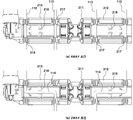
이때 가이드와이어(113)는 상하방향으로 연장되는 일자형으로서 고정와이어(110)와 상하나사봉(214) 사이에 형성되어, 베이스플레이트(210)의 상하 이동을 가이드하는 동시에 지지하게 되며, 이때 서포트부(200)는 상부패드(250)를 전후방향 및 상하방향으로 이동시킬 수 있는 4웨이형으로 작동 가능하다.At this time, the
여기서, 상기 일자형의 가이드와이어(4웨이용 가이드와이어)(113) 대신 중앙부가 직각으로 연속 절곡된 가이드와이어(2웨이용 가이드와이어)(114)를 채택하는 경우 상기 서포트부(200)는 상부패드(250)를 전후방향으로만 이동시킬 수 있는 2웨이형으로 작동 가능하다.Here, when a guide wire (guide wire for two ways) 114 is used, in which a center portion is continuously bent at a right angle instead of the straight type guide wire (four-way guide wire) Way type that can move the
따라서, 가이드와이어(113,114)의 형태를 달리하는 것에 의해, 럼버 서포트를 전후방향 작동만 가능한 2웨이형으로 사용하거나 또는 상하방향 작동까지 가능한 4웨이형으로 사용할 수 있다.Therefore, by changing the shapes of the
상기 2웨이용 가이드와이어(114)를 사용하는 경우 레프트플레이트(212) 및 라이트플레이트(213)의 하부에 형성된 와이어고정부(217) 중 대각선상에 위치하는 한 쌍의 와이어고정부(217)를 사용하여 가이드와이어(114)를 고정하게 되고, 고정와이어(110)는 와이어고정부(217)에 장착하지 않는다. When the two-
그리고 상기 2웨이용 가이드와이어(114)의 상하 유동을 방지하기 위해, 레프트플레이트(212) 및 라이트플레이트(213)의 하부에는 각각 와이어지지부(218)가 구비된다.In order to prevent the two-
상기 와이어지지부(218)는 좌우방향으로 연장되는 2웨이용 가이드와이어(114)의 중앙부를 상하 양측에서 밀착 지지함으로써 가이드와이어(114)의 상하 유동을 방지한다.The
이하, 상기와 같이 구성되는 럼버 서포트의 작동을 도 6 및 도 7을 참조하여 설명한다.Hereinafter, the operation of the lumbar support constructed as described above will be described with reference to Figs. 6 and 7. Fig.
도 6을 참조하면, 좌우나사봉(223)의 일측에 연결된 좌우구동모터(224)가 구동되어 좌우나사봉(223)이 회전하게 되면 레프트너트(221)와 라이트너트(222)가 서로 반대방향으로 이동하여 서로 멀어지거나 또는 서로 가까워지게 되는 동시에, 레프트암(241)과 라이트암(242)의 내측단이 베이스플레이트(210)의 외측으로 이동되면서 서로 멀어지게 되거나 또는 베이스플레이트(210)의 내측으로 이동되면서 서로 가까워지게 된다.6, when the left and right driving
이때 레프트암(241)과 라이트암(242)의 중간에 레프트링크(231) 및 라이트링크(232)의 내측단이 힌지 결합되어 있어 레프트암(241)과 라이트암(242)의 좌우 이동에 제약이 발생하게 되며, 이에 의해 레프트암(241)과 라이트암(242)의 내측단 및 레프트링크(231)와 라이트링크(232)의 내측단 간에 좌우 거리가 가까워짐(혹은 전후 거리가 멀어짐)에 따라 레프트암(241)과 라이트암(242)의 외측단이 탑승자의 등쪽으로 전진하게 되고, 반대로 레프트암(241)과 라이트암(242)의 내측단 및 레프트링크(231)와 라이트링크(232)의 내측단 간에 좌우 거리가 멀어짐(혹은 전후 거리가 가까워짐)에 따라 레프트암(241)과 라이트암(242)의 외측단이 탑승자의 등쪽에서 후진하게 된다.At this time, the inner ends of the
이에 따라 상부패드(250)가 전후방향으로 이동하여 상부패드(250)와 마주하여 접촉하고 있는 컴포트매트(미도시)의 하부를 탑승자의 등쪽으로 전진시키거나 또는 탑승자의 등쪽에서 후진시키게 된다.Accordingly, the
한편, 도 7을 참조하면, 상하나사봉(214)의 일측에 연결된 상하구동모터(215)가 작동되어 상하나사봉(214)이 회전하게 되면 상하나사봉(214)과 나선 결합된 센터플레이트(211)가 상하나사봉(214)의 회전방향에 따라 상하로 이동하게 되며, 이에 따라 베이스플레이트(210)가 상하로 이동하면서 상부패드(250)가 컴포트매트(미도시)를 지지하는 부위가 상하방향으로 변경 가능하게 되고, 결국 탑승자의 등을 지지하는 컴포트매트의 부위가 변동 가능하게 되어 탑승자의 자세 및 신체 조건에 따라 탑승자의 등을 최적으로 받쳐줄 수 있게 된다.7, when the up / down driving
이상으로 본 발명의 실시예에 대해 상세히 설명하였는바, 본 발명의 권리범위는 상술한 실시예에 한정되지 않으며, 다음의 특허청구범위에서 정의하고 있는 본 발명의 기본 개념을 이용한 당업자의 여러 변형 및 개량 형태 또한 본 발명의 권리범위에 포함된다.
While the present invention has been particularly shown and described with reference to exemplary embodiments thereof, it is to be understood that the scope of the present invention is not limited to the disclosed exemplary embodiments. Modified forms are also included within the scope of the present invention.
100 : 와이어부 110 : 고정와이어
111 : 상부가이드브라켓 112 : 하부가이드브라켓
113 : 가이드와이어(4웨이용 가이드와이어)
114 : 가이드와이어(2웨이용 가이드와이어)
120 : 크로스와이어 200 : 서포트부
210 : 베이스플레이트 211 : 센터플레이트
211a,211b : 체결돌기 212 : 레프트플레이트
212a : 결합홀 213 : 라이트플레이트
213a : 결합홀 214 : 상하나사봉
215 : 상하구동모터 216 : 제1방향전환부
217 : 와이어고정부 218 : 와이어지지부
220 : 너트부 221 : 레프트너트
222 : 라이트너트 223 : 좌우나사봉
224 : 좌우구동모터 225 : 제2방향전환부
230 : 링크부 231 : 레프트링크
232 : 라이트링크 240 : 암부
241 : 레프트암 241a : 체결홈
241b : 걸림돌기 242 : 라이트암
242a : 체결홈 242b : 걸림돌기
250 : 상부패드 251,252 : 암결합부
251a,252a : 걸림홀 270 : 컴포트매드
280 : 클립100: wire portion 110: fixed wire
111: upper guide bracket 112: lower guide bracket
113: Guide wire (4-way guide wire)
114: Guide wire (2-way guide wire)
120: Cross wire 200: Support part
210: base plate 211: center plate
211a, 211b: fastening protrusion 212:
212a: coupling hole 213: light plate
213a: Coupling hole 214:
215: Up / down driving motor 216:
217: wire fixing portion 218: wire supporting portion
220: Nut portion 221: Left nut
222: Light nut 223:
224: a left-right drive motor 225: a second-
230: Link unit 231: Left link
232: light link 240: dark section
241:
241b: locking projection 242: light arm
242a: fastening
250:
251a, 252a: latching hole 270:
280: Clip
Claims (7)
상기 시트백 프레임에 설치된 고정와이어에 승강 이동가능하게 설치되는 베이스플레이트;
상기 베이스플레이트의 양측 상부에 각각 좌우방향으로 슬라이드 가능하게 결합된 레프트너트와 라이트너트로 이루어진 너트부;
상기 너트부의 바깥측으로 이격되게 위치되어 각각 베이스플레이트의 양측 상부에 일단이 힌지 결합되는 레프트링크와 라이트링크로 이루어진 링크부;
상기 너트부의 슬라이드 이동시 상기 링크부에 의해 좌우 이동이 제한되고 전후방향으로 들리게 되는 레프트암과 라이트암으로 이루어진 암부;
상기 레프트너트와 라이트너트에 좌우방향으로 관통하여 나선 결합되고, 회전시 레프트너트와 라이트너트를 서로 반대방향으로 이동하게 하는 나선구조를 갖는 좌우나사봉;
을 포함하고,
상기 베이스플레이트는 중앙에 배치되는 센터플레이트와, 상기 센터플레이트의 좌우 양측에 결합되는 레프트플레이트 및 라이트플레이트로 구성되며, 상기 센터플레이트를 포함한 베이스플레이트는 구동수단에 의해 상하로 승강 이동하게 되는 것을 특징으로 하는 자동차의 럼버 서포트 장치.
A lumbar support device installed in a seat back frame of a vehicle seat back to support a passenger's back,
A base plate mounted on the fixed wire provided on the seat back frame so as to be movable up and down;
A nut unit comprising a left nut and a light nut slidably coupled to upper portions of both sides of the base plate in a left-right direction;
A link portion including a left link and a right link which are spaced apart from the nut portion and are hinged to both ends of the base plate, respectively;
An arm portion having a left arm and a right arm which are limited in lateral movement by the link portion when the nut portion is slid and are heard in the forward and backward directions;
Left and right screws having a spiral structure that is spirally coupled to the left and right light nuts in the left and right directions and causes the left and right light nuts to move in opposite directions during rotation;
/ RTI >
The base plate includes a center plate disposed at the center and a left plate and a light plate coupled to both left and right sides of the center plate. The base plate including the center plate is moved up and down by a driving means The lumbar support apparatus of the automobile.
상기 좌우나사봉의 일단에 연결되어 회전력을 공급할 수 있는 좌우구동모터를 포함하는 것을 특징으로 하는 자동차의 럼버 서포트 장치.
The method according to claim 1,
And a left and right driving motor connected to one end of the left and right screw rods and capable of supplying a rotational force.
상기 레프트너트는 베이스플레이트의 좌측 상부에 좌우방향으로 슬라이드 가능하게 결합되고, 상기 라이트너트는 베이스플레이트의 우측 상부에 좌우방향으로 슬라이드 가능하게 결합되고, 상기 레프트링크는 레프트너트의 좌측에 이격되게 위치되어 베이스플레이트의 좌측 상부에 일단이 힌지 결합되고, 상기 라이트링크는 라이트너트의 우측에 이격되게 위치되어 베이스플레이트의 우측 상부에 일단이 힌지 결합되고, 상기 레프트암은 내측단이 레프트너트에 힌지 결합되고 중앙부에 레프트링크의 타단이 힌지 결합되고, 상기 라이트암은 내측단이 라이트너트에 힌지 결합되고 중앙부에 라이트링크의 타단이 힌지 결합되는 것을 특징으로 하는 자동차의 럼버 서포트 장치.
The method according to claim 1,
The left nut is slidably coupled to the upper left portion of the base plate in the left-right direction, the light nut is slidably coupled to the upper right portion of the base plate in the left-right direction, and the left- And the light link is hinged to the right upper portion of the base plate so as to be hinged to the right side of the base plate, and the left end of the left arm is hinged to the left nut, And the other end of the left link is hinged to the center portion, and the inner end of the right arm is hinged to the light nut, and the other end of the right link is hinged to the center portion.
상기 구동수단은 센터플레이트에 이 센터플레이트를 상하방향으로 관통하는 상하나사봉이 나선 결합되고, 상기 상하나사봉이 고정와이어의 상하 양측에 설치된 상부가이드브라켓과 하부가이드브라켓 사이에 회전가능하게 고정되며, 상기 상하나사봉의 일단에 회전력을 공급할 수 있는 상하구동모터가 구비되는 구조로 이루어지는 것을 특징으로 하는 자동차의 럼버 서포트 장치.
The method according to claim 1,
The upper and lower guide brackets are rotatably fixed between upper and lower guide brackets provided on upper and lower sides of the fixed wire, respectively, And a vertical drive motor capable of supplying a rotational force to one end of the upper one-side bar.
상기 레프트암의 외측단에 일단이 결합되고 라이트암의 외측단에 타단이 결합되는 상부패드가 구비된 것을 특징으로 하는 자동차의 럼버 서포트 장치.
The method according to claim 1,
And an upper pad having one end coupled to an outer end of the left arm and the other end coupled to an outer end of the light arm.
상기 베이스플레이트는 중앙에 배치되는 센터플레이트와 이 센터플레이트의 좌우 양측에 연결되는 레프트플레이트 및 라이트플레이트로 구성되며, 상기 레프트플레이트와 라이트플레이트의 하부에는 가이드와이어의 전후 이탈 방지를 위한 복수의 와이어고정부가 구비된 것을 특징으로 하는 자동차의 럼버 서포트 장치.
The method according to claim 1,
The base plate includes a center plate disposed at the center and a left plate and a light plate connected to both left and right sides of the center plate. A plurality of wires are fixed to a lower portion of the left plate and the right plate, And a lumbar support mechanism for supporting the lumbar support of the vehicle.
상기 베이스플레이트는 중앙에 배치되는 센터플레이트와 이 센터플레이트의 좌우 양측에 연결되는 레프트플레이트 및 라이트플레이트로 구성되며, 상기 레프트플레이트와 라이트플레이트의 하부에는 가이드와이어의 상하 유동 방지를 위한 와이어지지부가 구비된 것을 특징으로 하는 자동차의 럼버 서포트 장치.
The method according to claim 1,
The base plate includes a center plate disposed at the center and a left plate and a light plate connected to both right and left sides of the center plate. A wire support portion for preventing upward / downward movement of the guide wire is provided below the left plate and the light plate Wherein the lumbar support mechanism comprises:
Priority Applications (2)
| Application Number | Priority Date | Filing Date | Title |
|---|---|---|---|
| KR1020140109329A KR101592754B1 (en) | 2014-08-22 | 2014-08-22 | Lumbar support for vehicle |
| US14/570,330 US9415714B2 (en) | 2014-08-22 | 2014-12-15 | Lumber support apparatus for vehicle |
Applications Claiming Priority (1)
| Application Number | Priority Date | Filing Date | Title |
|---|---|---|---|
| KR1020140109329A KR101592754B1 (en) | 2014-08-22 | 2014-08-22 | Lumbar support for vehicle |
Publications (1)
| Publication Number | Publication Date |
|---|---|
| KR101592754B1 true KR101592754B1 (en) | 2016-02-12 |
Family
ID=55347576
Family Applications (1)
| Application Number | Title | Priority Date | Filing Date |
|---|---|---|---|
| KR1020140109329A Active KR101592754B1 (en) | 2014-08-22 | 2014-08-22 | Lumbar support for vehicle |
Country Status (2)
| Country | Link |
|---|---|
| US (1) | US9415714B2 (en) |
| KR (1) | KR101592754B1 (en) |
Cited By (5)
| Publication number | Priority date | Publication date | Assignee | Title |
|---|---|---|---|---|
| KR102415251B1 (en) * | 2021-12-10 | 2022-06-30 | 주식회사 금창 | Lumber support for vehicle seat with push type avtuating block |
| KR102415256B1 (en) * | 2021-12-14 | 2022-06-30 | 주식회사 금창 | Lumber support for vehicle seat with rotating support rod |
| CN115158125A (en) * | 2021-04-02 | 2022-10-11 | Dsc 有限公司-东滩 | Seat support drive unit and support assembly |
| US11479156B2 (en) * | 2020-11-04 | 2022-10-25 | Toyota Boshoku Kabushiki Kaisha | Lumbar support device |
| US20230322137A1 (en) * | 2022-04-06 | 2023-10-12 | Brose Fahrzeugteile SE & Co. Kommanditgesellschaft, Coburg | Lumbar adjustment assembly |
Families Citing this family (4)
| Publication number | Priority date | Publication date | Assignee | Title |
|---|---|---|---|---|
| KR101664697B1 (en) * | 2015-06-02 | 2016-10-10 | 현대자동차주식회사 | Lumbar support assembly |
| DE102016207620A1 (en) | 2016-05-03 | 2017-11-09 | Brose Fahrzeugteile Gmbh & Co. Kg, Coburg | Adjustment device for a seat element of a vehicle seat |
| DE102017105920A1 (en) * | 2017-03-20 | 2018-09-20 | Brose Fahrzeugteile Gmbh & Co. Kommanditgesellschaft, Coburg | Adjustment device for a vehicle seat |
| CN111038348B (en) * | 2020-01-03 | 2024-07-16 | 广东西北航空科技股份有限公司 | Chair seat |
Citations (2)
| Publication number | Priority date | Publication date | Assignee | Title |
|---|---|---|---|---|
| JPH0534958U (en) * | 1991-10-21 | 1993-05-14 | 株式会社タチエス | Lumber support device |
| KR20130012317A (en) * | 2011-07-25 | 2013-02-04 | (주)디에스시 | 4-way lumbar support assembly |
Family Cites Families (13)
| Publication number | Priority date | Publication date | Assignee | Title |
|---|---|---|---|---|
| US4295681A (en) * | 1980-02-19 | 1981-10-20 | Uop Inc. | Seat having lumbar support and vertical height adjustment mechanism therefor |
| US4339150A (en) * | 1980-05-05 | 1982-07-13 | Gmsr Ortho Enterprises, Inc. | Back support construction |
| US4657304A (en) * | 1986-06-06 | 1987-04-14 | Itt Corporation | Adjustable headrest |
| GB2194729B (en) * | 1986-09-04 | 1990-03-14 | Gen Motors Corp | Improved vehicle headrest |
| US4981325A (en) * | 1988-08-25 | 1991-01-01 | Dennis Zacharkow | Posture support with multi-planar adjustment |
| US5088790A (en) * | 1990-05-21 | 1992-02-18 | Lear Seating Corporation | Adjustable lumbar support mechanism for a vehicular seat |
| US5553919A (en) * | 1994-10-11 | 1996-09-10 | Excellence Lumbar Corporation | Scissor jack lumbar support |
| DE20313925U1 (en) * | 2003-09-04 | 2004-10-07 | Brose Fahrzeugteile Gmbh & Co. Kg, Coburg | Backrest structure for a motor vehicle seat |
| KR101006730B1 (en) | 2008-07-22 | 2011-01-10 | (주)디에스시 | Lumber Support Device |
| DE102008047248A1 (en) * | 2008-09-10 | 2010-03-11 | Brose Fahrzeugteile Gmbh & Co. Kommanditgesellschaft, Coburg | Spindle drive for a lumbar support in the backrest structure of a motor vehicle seat |
| KR20120098236A (en) | 2011-02-28 | 2012-09-05 | (주)디에스시 | 4-way lumbar support assembly |
| KR20120119281A (en) | 2011-04-21 | 2012-10-31 | (주)디에스시 | 4-way lumbar support assembly |
| US9193287B2 (en) * | 2012-09-13 | 2015-11-24 | Leggett & Platt Canada Co. | Lumbar support system |
-
2014
- 2014-08-22 KR KR1020140109329A patent/KR101592754B1/en active Active
- 2014-12-15 US US14/570,330 patent/US9415714B2/en active Active
Patent Citations (2)
| Publication number | Priority date | Publication date | Assignee | Title |
|---|---|---|---|---|
| JPH0534958U (en) * | 1991-10-21 | 1993-05-14 | 株式会社タチエス | Lumber support device |
| KR20130012317A (en) * | 2011-07-25 | 2013-02-04 | (주)디에스시 | 4-way lumbar support assembly |
Cited By (9)
| Publication number | Priority date | Publication date | Assignee | Title |
|---|---|---|---|---|
| US11479156B2 (en) * | 2020-11-04 | 2022-10-25 | Toyota Boshoku Kabushiki Kaisha | Lumbar support device |
| CN115158125A (en) * | 2021-04-02 | 2022-10-11 | Dsc 有限公司-东滩 | Seat support drive unit and support assembly |
| KR20220137447A (en) * | 2021-04-02 | 2022-10-12 | 주식회사 디에스시동탄 | Support driver and support assembly including the same |
| KR102597544B1 (en) | 2021-04-02 | 2023-11-03 | 주식회사 디에스시동탄 | Support driver and support assembly including the same |
| CN115158125B (en) * | 2021-04-02 | 2024-01-23 | Dsc 有限公司-东滩 | Seat support driving part and support assembly |
| KR102415251B1 (en) * | 2021-12-10 | 2022-06-30 | 주식회사 금창 | Lumber support for vehicle seat with push type avtuating block |
| KR102415256B1 (en) * | 2021-12-14 | 2022-06-30 | 주식회사 금창 | Lumber support for vehicle seat with rotating support rod |
| US20230322137A1 (en) * | 2022-04-06 | 2023-10-12 | Brose Fahrzeugteile SE & Co. Kommanditgesellschaft, Coburg | Lumbar adjustment assembly |
| US11820268B2 (en) * | 2022-04-06 | 2023-11-21 | Brose Fahrzeugteile SE & Co. Kommanditgesellschaft, Coburg | Lumbar adjustment assembly |
Also Published As
| Publication number | Publication date |
|---|---|
| US9415714B2 (en) | 2016-08-16 |
| US20160052436A1 (en) | 2016-02-25 |
Similar Documents
| Publication | Publication Date | Title |
|---|---|---|
| KR101592754B1 (en) | Lumbar support for vehicle | |
| US11338714B2 (en) | Vehicle seat with cantilevered headrest assembly and positioning system | |
| CN101417621B (en) | Motor vehicle seat | |
| KR101585850B1 (en) | Power headrest apparatus | |
| EP1104361B1 (en) | Adjustable vehicle seat | |
| KR101725414B1 (en) | Leg rest apparatus for vehicle seat | |
| EP2873555A1 (en) | Vehicle seat | |
| KR101664697B1 (en) | Lumbar support assembly | |
| JP2015098194A5 (en) | ||
| JPH1059037A (en) | Child seat having tiltable back | |
| CN106536273B (en) | Headrest inclination angle adjusting module | |
| KR101620231B1 (en) | Apparatus for reclining rear seat for vehicle | |
| KR101724915B1 (en) | Apparatus for reclining rear seat for vehicle | |
| KR20160107183A (en) | Lumbar support system | |
| KR101470213B1 (en) | Apparatus for seat side bolster of vehicle | |
| US12208711B2 (en) | Seat for vehicle | |
| KR20130012317A (en) | 4-way lumbar support assembly | |
| KR101746457B1 (en) | Apparatus for reclining rear seat for vehicle | |
| KR20120119281A (en) | 4-way lumbar support assembly | |
| JP2022110553A (en) | vehicle seat | |
| KR101945797B1 (en) | Power headresting apparatus | |
| KR101220944B1 (en) | Lumbar support assembly for vehicle | |
| KR20250014327A (en) | Seat adjust apparatus for mobility | |
| KR101785277B1 (en) | Apparatus for moving seat cushion of vehicle | |
| CN114394043A (en) | Framework of adjustable seat and adjustable seat |
Legal Events
| Date | Code | Title | Description |
|---|---|---|---|
| PA0109 | Patent application |
St.27 status event code: A-0-1-A10-A12-nap-PA0109 |
|
| PA0201 | Request for examination |
St.27 status event code: A-1-2-D10-D11-exm-PA0201 |
|
| D13-X000 | Search requested |
St.27 status event code: A-1-2-D10-D13-srh-X000 |
|
| D14-X000 | Search report completed |
St.27 status event code: A-1-2-D10-D14-srh-X000 |
|
| PE0902 | Notice of grounds for rejection |
St.27 status event code: A-1-2-D10-D21-exm-PE0902 |
|
| P11-X000 | Amendment of application requested |
St.27 status event code: A-2-2-P10-P11-nap-X000 |
|
| P13-X000 | Application amended |
St.27 status event code: A-2-2-P10-P13-nap-X000 |
|
| E701 | Decision to grant or registration of patent right | ||
| PE0701 | Decision of registration |
St.27 status event code: A-1-2-D10-D22-exm-PE0701 |
|
| R17-X000 | Change to representative recorded |
St.27 status event code: A-3-3-R10-R17-oth-X000 |
|
| R18-X000 | Changes to party contact information recorded |
St.27 status event code: A-3-3-R10-R18-oth-X000 |
|
| GRNT | Written decision to grant | ||
| PR0701 | Registration of establishment |
St.27 status event code: A-2-4-F10-F11-exm-PR0701 |
|
| PR1002 | Payment of registration fee |
St.27 status event code: A-2-2-U10-U11-oth-PR1002 Fee payment year number: 1 |
|
| PG1601 | Publication of registration |
St.27 status event code: A-4-4-Q10-Q13-nap-PG1601 |
|
| FPAY | Annual fee payment |
Payment date: 20190130 Year of fee payment: 4 |
|
| PR1001 | Payment of annual fee |
St.27 status event code: A-4-4-U10-U11-oth-PR1001 Fee payment year number: 4 |
|
| R18-X000 | Changes to party contact information recorded |
St.27 status event code: A-5-5-R10-R18-oth-X000 |
|
| R18-X000 | Changes to party contact information recorded |
St.27 status event code: A-5-5-R10-R18-oth-X000 |
|
| FPAY | Annual fee payment |
Payment date: 20191219 Year of fee payment: 5 |
|
| PR1001 | Payment of annual fee |
St.27 status event code: A-4-4-U10-U11-oth-PR1001 Fee payment year number: 5 |
|
| PR1001 | Payment of annual fee |
St.27 status event code: A-4-4-U10-U11-oth-PR1001 Fee payment year number: 6 |
|
| PR1001 | Payment of annual fee |
St.27 status event code: A-4-4-U10-U11-oth-PR1001 Fee payment year number: 7 |
|
| P14-X000 | Amendment of ip right document requested |
St.27 status event code: A-5-5-P10-P14-nap-X000 |
|
| PN2301 | Change of applicant |
St.27 status event code: A-5-5-R10-R13-asn-PN2301 St.27 status event code: A-5-5-R10-R11-asn-PN2301 |
|
| PR1001 | Payment of annual fee |
St.27 status event code: A-4-4-U10-U11-oth-PR1001 Fee payment year number: 8 |
|
| PR1001 | Payment of annual fee |
St.27 status event code: A-4-4-U10-U11-oth-PR1001 Fee payment year number: 9 |
|
| PR1001 | Payment of annual fee |
St.27 status event code: A-4-4-U10-U11-oth-PR1001 Fee payment year number: 10 |
|
| PR1001 | Payment of annual fee |
St.27 status event code: A-4-4-U10-U11-oth-PR1001 Fee payment year number: 11 |