KR101575188B1 - Dual nondestructive defect detecting system combined with a local magnetic signal removal unit - Google Patents
Dual nondestructive defect detecting system combined with a local magnetic signal removal unit Download PDFInfo
- Publication number
- KR101575188B1 KR101575188B1 KR1020140182609A KR20140182609A KR101575188B1 KR 101575188 B1 KR101575188 B1 KR 101575188B1 KR 1020140182609 A KR1020140182609 A KR 1020140182609A KR 20140182609 A KR20140182609 A KR 20140182609A KR 101575188 B1 KR101575188 B1 KR 101575188B1
- Authority
- KR
- South Korea
- Prior art keywords
- metal roll
- magnetic field
- defect
- unit
- measurement
- Prior art date
Links
- 230000007547 defect Effects 0.000 title claims abstract description 139
- 230000009977 dual effect Effects 0.000 title claims abstract description 19
- 229910052751 metal Inorganic materials 0.000 claims abstract description 100
- 239000002184 metal Substances 0.000 claims abstract description 100
- 230000001066 destructive effect Effects 0.000 claims abstract description 42
- 238000007689 inspection Methods 0.000 claims abstract description 28
- 238000005096 rolling process Methods 0.000 claims abstract description 12
- 238000005259 measurement Methods 0.000 claims description 62
- 239000002131 composite material Substances 0.000 claims description 26
- 238000000034 method Methods 0.000 claims description 22
- 230000002093 peripheral effect Effects 0.000 claims description 9
- 238000001514 detection method Methods 0.000 claims description 6
- 230000005684 electric field Effects 0.000 claims description 5
- 239000000696 magnetic material Substances 0.000 claims description 5
- 230000005415 magnetization Effects 0.000 claims description 5
- 230000008030 elimination Effects 0.000 claims description 4
- 238000003379 elimination reaction Methods 0.000 claims description 4
- 238000009738 saturating Methods 0.000 claims description 4
- 230000001939 inductive effect Effects 0.000 claims description 3
- 239000012212 insulator Substances 0.000 claims description 2
- 230000000704 physical effect Effects 0.000 abstract description 10
- 238000000691 measurement method Methods 0.000 abstract description 4
- 239000004020 conductor Substances 0.000 description 4
- 229910000976 Electrical steel Inorganic materials 0.000 description 3
- 230000035515 penetration Effects 0.000 description 3
- XEEYBQQBJWHFJM-UHFFFAOYSA-N Iron Chemical compound [Fe] XEEYBQQBJWHFJM-UHFFFAOYSA-N 0.000 description 2
- XUIMIQQOPSSXEZ-UHFFFAOYSA-N Silicon Chemical compound [Si] XUIMIQQOPSSXEZ-UHFFFAOYSA-N 0.000 description 2
- 238000004458 analytical method Methods 0.000 description 2
- 230000007797 corrosion Effects 0.000 description 2
- 238000005260 corrosion Methods 0.000 description 2
- 230000002950 deficient Effects 0.000 description 2
- 230000006698 induction Effects 0.000 description 2
- 238000009434 installation Methods 0.000 description 2
- 239000007769 metal material Substances 0.000 description 2
- 230000035945 sensitivity Effects 0.000 description 2
- 229910052710 silicon Inorganic materials 0.000 description 2
- 239000010703 silicon Substances 0.000 description 2
- 229910000831 Steel Inorganic materials 0.000 description 1
- 230000003213 activating effect Effects 0.000 description 1
- 229910045601 alloy Inorganic materials 0.000 description 1
- 239000000956 alloy Substances 0.000 description 1
- 230000000295 complement effect Effects 0.000 description 1
- 238000013016 damping Methods 0.000 description 1
- 210000003298 dental enamel Anatomy 0.000 description 1
- 230000000694 effects Effects 0.000 description 1
- 230000004907 flux Effects 0.000 description 1
- 229910001026 inconel Inorganic materials 0.000 description 1
- 229910052742 iron Inorganic materials 0.000 description 1
- 239000000463 material Substances 0.000 description 1
- 150000002739 metals Chemical class 0.000 description 1
- 230000003287 optical effect Effects 0.000 description 1
- 230000035699 permeability Effects 0.000 description 1
- 238000003672 processing method Methods 0.000 description 1
- 230000035939 shock Effects 0.000 description 1
- 239000010959 steel Substances 0.000 description 1
- 229920003002 synthetic resin Polymers 0.000 description 1
- 239000000057 synthetic resin Substances 0.000 description 1
Images


Classifications
-
- G—PHYSICS
- G01—MEASURING; TESTING
- G01N—INVESTIGATING OR ANALYSING MATERIALS BY DETERMINING THEIR CHEMICAL OR PHYSICAL PROPERTIES
- G01N33/00—Investigating or analysing materials by specific methods not covered by groups G01N1/00 - G01N31/00
- G01N33/20—Metals
- G01N33/204—Structure thereof, e.g. crystal structure
- G01N33/2045—Defects
-
- G—PHYSICS
- G01—MEASURING; TESTING
- G01N—INVESTIGATING OR ANALYSING MATERIALS BY DETERMINING THEIR CHEMICAL OR PHYSICAL PROPERTIES
- G01N27/00—Investigating or analysing materials by the use of electric, electrochemical, or magnetic means
- G01N27/72—Investigating or analysing materials by the use of electric, electrochemical, or magnetic means by investigating magnetic variables
- G01N27/82—Investigating or analysing materials by the use of electric, electrochemical, or magnetic means by investigating magnetic variables for investigating the presence of flaws
- G01N27/90—Investigating or analysing materials by the use of electric, electrochemical, or magnetic means by investigating magnetic variables for investigating the presence of flaws using eddy currents
- G01N27/9006—Details, e.g. in the structure or functioning of sensors
-
- G—PHYSICS
- G01—MEASURING; TESTING
- G01N—INVESTIGATING OR ANALYSING MATERIALS BY DETERMINING THEIR CHEMICAL OR PHYSICAL PROPERTIES
- G01N29/00—Investigating or analysing materials by the use of ultrasonic, sonic or infrasonic waves; Visualisation of the interior of objects by transmitting ultrasonic or sonic waves through the object
- G01N29/22—Details, e.g. general constructional or apparatus details
Landscapes
- Chemical & Material Sciences (AREA)
- Health & Medical Sciences (AREA)
- Life Sciences & Earth Sciences (AREA)
- General Health & Medical Sciences (AREA)
- Immunology (AREA)
- Pathology (AREA)
- Analytical Chemistry (AREA)
- Biochemistry (AREA)
- Physics & Mathematics (AREA)
- General Physics & Mathematics (AREA)
- Chemical Kinetics & Catalysis (AREA)
- Electrochemistry (AREA)
- Crystallography & Structural Chemistry (AREA)
- Engineering & Computer Science (AREA)
- Food Science & Technology (AREA)
- Medicinal Chemistry (AREA)
- Investigating Or Analyzing Materials By The Use Of Magnetic Means (AREA)
- Investigating Or Analyzing Materials By The Use Of Ultrasonic Waves (AREA)
Abstract
본 발명은 국부 자계신호 제거 유닛을 결합한 듀얼 비파괴 결함 탐상 시스템에 관한 것으로서, 더욱 상세하게는 압연공정 장치 금속 롤을 와전류 결함 측정방법으로 측정할 때, 금속재료의 압연공정에서 발생한 스트레스로 인한 금속 롤의 물성변화에 기인하는 자계신호를 국부 자계신호 제거 유닛으로 제거하여 금속 롤의 결함 탐상오류를 개선한 듀얼 비파괴 결함 탐상 시스템의 제공에 관한 것이다.The present invention relates to a dual non-destructive defect inspection system incorporating a local magnetic field signal rejection unit, and more particularly, to a dual non-destructive defect inspection system in which a metal roll of a rolling process apparatus is measured by an eddy current defect measurement method, The present invention relates to a dual non-destructive defect inspection system in which a magnetic field signal caused by a change in physical properties of a metal roll is removed by a local magnetic field signal removing unit to improve a defect inspection error of a metal roll.
Description
본 발명은 국부 자계신호 제거 유닛을 결합한 듀얼 비파괴 결함 탐상 시스템에 관한 것으로서, 더욱 상세하게는 압연공정 장치 금속 롤을 와전류 결함 측정방법으로 측정할 때, 금속재료의 압연공정에서 발생한 스트레스로 인한 금속 롤의 물성변화에 기인하는 자계신호를 국부 자계신호 제거 유닛으로 제거하여 금속 롤의 결함 탐상오류를 개선한 듀얼 비파괴 결함 탐상 시스템의 제공에 관한 것이다. The present invention relates to a dual non-destructive defect inspection system incorporating a local magnetic field signal rejection unit, and more particularly, to a dual non-destructive defect inspection system in which a metal roll of a rolling process apparatus is measured by an eddy current defect measurement method, The present invention relates to a dual non-destructive defect inspection system in which a magnetic field signal caused by a change in physical properties of a metal roll is removed by a local magnetic field signal removing unit to improve a defect inspection error of a metal roll.
와전류 금속 결함 탐상 방법은 도체에 방향이 바뀌는 자계를 가까이하여 그 도체에 와전류를 흐르게 한다. 만약 도체에 공간을 갖는 물리적 결함이 존재하면 와전류의 흐름은 난조가 생기고, 이 난조의 측정으로 도체 내의 결함을 검사한다. 이때 결함은 크랙, 미세홀 또는 부식 등이다. 이 방법은 비파괴 검사방법으로 발전소, 항공, 우주, 도로 또는 빌딩에 사용된 금속의 피로 또는 부식에 따른 결함발생을 검사하는데 많이 사용되고 있으며, 검사 속도가 빠른 장점을 이용해 강판의 생산 후 공정에서 공정 중 발생한 결함 여부를 테스트하는데 이용된다.An eddy current metal defect detection method causes an eddy current to flow in a conductor close to a magnetic field whose direction changes. If there is a physical defect with a space in the conductor, the flow of the eddy current is hunted and the defect in the conductor is inspected by measuring the hunting. Defects include cracks, microholes or corrosion. This method is a non-destructive inspection method which is widely used to inspect the occurrence of defects due to fatigue or corrosion of metals used in power plants, aerospace, aerospace, roads or buildings, It is used to test whether or not a defect has occurred.
와전류 결함 탐상 방법은 주로 표면의 결함을 검사하나 전자기파의 금속에 대한 침투깊이에 따라 탐상 깊이가 결정된다. 침투깊이는 두께에 따라 와전류의 감쇄로 이어지며 금속의 두께 측정원리로 사용되며, 마모된 자동차 디스크 등의 두께를 비파괴방법으로 측정하는데 사용된다.The eddy current defect inspection method mainly examines defects on the surface, but the depth of penetration depends on the depth of penetration of the electromagnetic wave into the metal. The depth of penetration leads to the eddy current damping according to the thickness. It is used as the principle of measuring the thickness of metal. It is used to measure the thickness of worn automobile disk by non-destructive method.
금속 롤 결함 탐상은 금속으로 만들어진 복수의 금속 롤러를 사용해 금속을 가공하는 압연공정 전에 금속 롤을 검사하는 것이다. 금속 압연공정은 저온 또는 고온에서 행하여지는데 저온공정 방법이 압연 중에 더 많은 스트레스를 금속 롤에 주게 되어 금속 롤의 물성이 변하게 된다. 금속 롤의 변한 물성은 결함탐상에 검사오류를 야기하고, 결함과 물성변화에 의한 신호를 분리하는 기술이 요구된다. Metal roll defect inspection is to inspect the metal roll before the rolling process to process the metal using a plurality of metal rollers made of metal. The metal rolling process is performed at a low temperature or a high temperature, but the low temperature processing method gives more stress to the metal roll during rolling, and the physical properties of the metal roll are changed. The changed physical properties of the metal rolls require inspection errors in defect inspection and techniques for separating signals due to defects and changes in physical properties.
금속에서 국부적인 물성변화는 스트레스에 의한 원자배열의 뒤틀림, 원자의 결원(vacancy) 등에 의해 발생하게 되고, 와전류 결함 탐상 시에 구동코일에 의해 국부적으로 자화되어 비교적 긴 시간동안 자력을 보유하는 상태로 된다. 이 자화신호는 유도자계를 변화시키며 물성변화 및 결함에서 발생하는 신호와 함께 탐지되어 결함만을 탐지해야 하는 금속 롤 결함 탐상장치의 본래의 목적에 방해가 된다. The change in the local physical properties of the metal is caused by the distortion of the atomic arrangement due to stress, vacancy of the atom, etc., and is locally magnetized by the driving coil during the eddy current defect detection, do. This magnetization signal changes the induction magnetic field and is interfered with the original purpose of the metal roll defect inspection apparatus, which is required to detect defects only in conjunction with changes in physical properties and signals generated from defects.
특허문헌 1은 와전류를 이용한 금속 롤 탐상 시 발생하는 금속 롤의 스트레스에 의한 물성변화와 결함에서 발생하는 신호를 분리하여 결함만 탐상하는 와전류 어레이 센서에 대한 기술을 제공하였으나 자계신호를 제거하지 못하는 단점이 있다. Patent Document 1 provides a technique for a eddy current array sensor that detects defects only by separating signals generated from defects and changes in physical properties due to stress of metal rolls generated during metal roll inspection using an eddy current, but disadvantage .
상기와 같은 문제점을 해결하고자 본 발명은 압연공정 장치 금속 롤을 와전류 결함 측정방법으로 측정할 때, 금속재료의 압연공정에서 발생한 스트레스로 인한 금속 롤의 물성변화에 기인하는 자계신호를 국부 자계신호 제거 유닛으로 제거하여 금속 롤의 결함 탐상오류를 개선한 듀얼 비파괴 결함 탐상 시스템을 제공하고자 한다.In order to solve the above problems, the present invention provides a method of measuring a magnetic field signal caused by a change in physical properties of a metal roll due to a stress generated in a rolling process of a metal material by measuring a local magnetic field signal To thereby provide a dual non-destructive defect inspection system which improves the defect inspection error of the metal roll.
상기의 해결하려는 과제를 위한 본 발명에 따른 듀얼 비파괴 결함 탐상 시스템은, 복수의 섹션을 가진 복합 하우징, 복합 하우징의 스캔방향 측에 설치되고, 금속 롤의 외주연에 소정의 간격을 두고 위치하여 포화 자계를 발생하는 국부 자계신호 제거 유닛, 복합하우징의 중앙에 위치되고 구동코일과 자계신호 검출부를 결합하여 설치된 와전류 결함 측정 유닛 및 복합하우징에서 상기 와전류 결함 측정 유닛의 일측에 설치되어 금속 롤의 표면 및 내부의 결함을 측정하는 초음파 결함 측정 유닛을 포함하는 것을 특징으로 한다. A dual non-destructive defect inspection system according to the present invention for solving the above-mentioned problem is provided with a composite housing having a plurality of sections, a composite housing provided at a side of the composite housing in a scanning direction, A local magnetic field signal removing unit for generating a magnetic field, an eddy current defect measuring unit located at the center of the composite housing and coupled to the driving coil and the magnetic field signal detecting unit, And an ultrasonic defect measuring unit for measuring an internal defect.
듀얼 비파괴 결함 탐상 시스템은, 금속 롤의 곡률반경에 따라 가변할 수 있게 비파괴 측정 장치 각각 유닛의 양측에 조인트로 연결된 롤러형 지지대, 상기 비파괴 결함 측정 장치 각각 유닛의 하부에 부착된 롤러형 바퀴, 비파괴 결함 측정 장치의 상부에 주변장치 및 디스플레이 유닛에서 주변장치를 제어하여 상하 좌우로 구동하는 컨트롤 유닛을 더 포함하여 와전류 결함 측정 및 초음파 결함 측정을 동시에 수행하여 금속 롤의 결함 유무를 경고하고 표시하는 것을 특징으로 한다.A dual non-destructive defect inspection system includes: a roller-type support that is jointed to both sides of a unit of a nondestructive measurement device so as to be variable in accordance with a radius of curvature of a metal roll; a roller wheel attached to the underside defect measurement device, Further comprising a control unit for controlling the peripheral device and the peripheral device in the upper part of the defect measuring device and driving the peripheral device in the up, down, left, and right directions to warn and display the presence or absence of a defect in the metal roll by simultaneously performing the eddy current defect measurement and the ultrasonic defect measurement .
상기 국부 자계신호 제거 유닛은 금속 롤을 자화하여 포화시키는 전기 자계 발생장치이고, 전기 자계 발생장치의 자심은 소프트 자성물질에 절연체가 코팅된 금속선이 권선되는 것을 특징으로 한다.The local magnetic field signal removing unit is an electric field generator for magnetizing and saturating a metal roll. The magnetic core of the electric field generator is characterized in that a metal wire coated with an insulator is wound around a soft magnetic material.
상기 국부 자계신호 제거 유닛은 금속롤 외주연상에 N극 및 S극이 동시에 인가된 것을 특징으로 한다.The local magnetic field signal removing unit is characterized in that N poles and S poles are simultaneously applied on the outer periphery of the metal roll.
상기 자심은 소프트 자성물질 판을 복수의 층으로 겹쳐서 제조하는 것을 특징으로 한다.The magnetic core is characterized in that a soft magnetic material plate is formed by overlaying a plurality of layers.
상기 국부 자계신호 제거 유닛은, 금속 롤을 자화하여 포화시키는 자계 세기를 가진 영구자석인 것을 특징으로 한다.The local magnetic field signal removing unit is a permanent magnet having a magnetic field strength for magnetizing and saturating a metal roll.
상기 복합 하우징은 비자성물질인 것을 특징으로 한다.The composite housing is characterized by being a non-magnetic material.
상기 복합 하우징의 금속 롤측 단면은 평면 또는 금속 롤의 곡률반경에 맞게 곡면을 형성하는 것을 특징으로 한다.Wherein the metal housing side surface of the composite housing forms a curved surface in conformity with the radius of curvature of the flat or metal roll.
상기 와전류 결함 측정 유닛 및 상기 초음파 결함 측정 유닛은 동시에 또는 선택적으로 운용하여 결함 측정 결과를 동시에 실시간으로 디스플레이하는 것을 특징으로 한다.Wherein the eddy current defect measurement unit and the ultrasonic defect measurement unit simultaneously or selectively operate to simultaneously display defect measurement results in real time.
회전하는 압연장치의 금속 롤에서 듀얼 비파괴 결함 탐상 시스템을 이용한 탐상 방법은, 금속 롤을 구동하여 회전시키는 단계, 와전류 측정 유닛을 구동하고 초기화 및 측정대기 단계, 초음파 측정 유닛을 구동하고 초기화 및 측정대기 단계, 국부 자계신호 제거 유닛에 의해 금속 롤에 포화 자계를 유도하는 단계 및 비파괴 결함 측정 장치를 정해진 속도에 따라 자화방향으로 이동하며 와전류 결함 측정 및 초음파 결함 측정을 동시에 수행하여 금속 롤의 표면 및 내부 결함을 탐상하는 단계를 포함하는 것을 특징으로 한다.A method of inspecting a metal roll of a rotating rolling apparatus using a dual non-destructive defect inspection system includes driving and rotating a metal roll, driving an eddy current measurement unit, initializing and measuring a waiting stage, driving an ultrasonic measuring unit, Inducing a saturation magnetic field in the metal roll by the local magnetic field signal removing unit and moving the non-destructive defect measuring apparatus in the magnetization direction in accordance with the determined speed, simultaneously performing the eddy current defect measurement and the ultrasonic defect measurement, And a step of detecting defects.
본 발명은 와전류 결함 탐상에 국부 자계신호 제거 유닛을 결합하여 금속 롤의 스트레스에 의한 물성변화 및 그에 따른 국부 자계신호의 발생을 제거하여 금속 롤의 결함을 보다 정확하고 빠르게 탐상할 수 있는 효과가 있다.The present invention has the effect of detecting the defects of the metal roll more accurately and rapidly by removing the local magnetic field signal removing unit from the eddy current defect detection to remove the change of physical properties due to the stress of the metal roll and the generation of the local magnetic field signal .
본 발명은 비파괴 방법인 비 접촉성 와전류 측정 유닛 및 접촉성 초음파 측정 유닛을 설치하여 금속 롤의 표면 및 내부의 결함을 동시에 측정할 수 있는 장점이 있다.The present invention is advantageous in that a non-contact eddy current measurement unit and a contact ultrasonic measurement unit, which are non-destructive methods, can be installed to simultaneously measure defects on the surface and inside of a metal roll.
본 발명은 와전류 결함 측정과 초음파 결함 측정을 동시에 수행하고 빠르게 결함신호를 비교하여 구별해낼 수 있어, 기존의 숙련된 전문가에 의한 측정 및 결함 분석이 가능한 것을 비숙련 인력에 의한 결함분석도 가능한 장점이 있다.The present invention is capable of performing both eddy-current defect measurement and ultrasonic defect measurement at the same time and quickly comparing and distinguishing defective signals so that it is possible to perform measurement and defect analysis by an existing skilled expert. have.
본 발명은 기존의 스트레스 센서를 이용한 자계신호 측정 장치가 불필요해 시스템 구축이 경제적이다.The present invention is economical because a magnetic field signal measuring device using a conventional stress sensor is unnecessary.
도 1은 본 발명에 의한 비파괴 결함 측정 장치의 설치도.
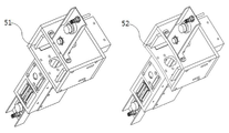
도 2는 본 발명의 비파괴 결함 측정 장치의 정면도 및 밑면도.
도 3은 자계신호 제거 유닛 전자석의 사시도 및 정면도.
도 4은 곡면형 복합 하우징의 사시도.
도 5은 국부 자계신호 제거 유닛의 적용 전후 결함 측정 데이터.
도 6는 본 발명의 측정방법에 대한 플로 차트.1 is an installation view of a non-destructive defect measuring apparatus according to the present invention;
2 is a front view and a bottom view of the non-destructive defect measuring apparatus of the present invention.
3 is a perspective view and a front view of a magnetic field elimination unit electromagnet.
4 is a perspective view of a curved composite housing;
5 is defect measurement data before and after application of the local magnetic field signal removal unit.
6 is a flow chart for a measurement method of the present invention.
이하 본 발명의 실시를 위한 구체적인 실시예를 도면을 참고하여 설명한다. 예시된 도면은 발명의 명확성을 위하여 핵심적인 내용만 확대 도시하고 부수적인 것은 생략하였으므로 도면에 한정하여 해석하여서는 아니 된다.Hereinafter, embodiments of the present invention will be described with reference to the drawings. The drawings illustrate only the essential features of the invention in order to facilitate clarity of the invention, and the accompanying drawings are not intended to be construed in a limiting sense.
본 발명에서 금속 롤이라 함은 외부 자계를 롤에 유도할 수 있는 금속 또는 합금 롤을 말하고, 탐상 대상의 결함은 공간을 갖는 물리적 결함을 의미하나 이에 한정된 것은 아니다. In the present invention, the metal roll refers to a metal or alloy roll capable of inducing an external magnetic field to a roll, and a defective object to be inspected refers to a physical defect having a space, but is not limited thereto.
본 발명은 압연공정 장치 금속 롤(10)의 결함을 측정하는 듀얼 비파괴 결함 탐상 시스템에 관한 것으로, 국부 자계신호 제거 유닛(20), 와전류 결함 측정 유닛(30), 초음파 결함 측정 유닛(40), 컨트롤 유닛, 롤러형 바퀴(11), 롤러형 지지대(12), 주변장치, 외부 지지프레임 및 디스플레이 유닛으로 구성된다.The present invention relates to a dual non-destructive defect inspection system for measuring defects in a metal roll (10) of a rolling process apparatus, comprising a local magnetic field signal removal unit (20), an eddy current defect measurement unit (30), an ultrasonic defect measurement unit A control unit, a
도 1은 듀얼 비파괴 결함 탐상 시스템에서 금속 롤에 접촉한 비파괴 결함 측정 장치를 나타내는 설치도이고, 도 2는 비파괴 결함 측정 장치(50)를 나타내는 측면도 및 밑면도이다.FIG. 1 is an installation view showing a non-destructive defect measuring apparatus in contact with a metal roll in a dual non-destructive defect inspection system, and FIG. 2 is a side view and a bottom view showing the non-destructive
비파괴 결함 측정 장치(50)는 국부 자계신호 제거 유닛(20), 와전류 결함 측정 유닛(30) 및 초음파 결함 측정 유닛(40)이 각각의 섹션이 있는 복합 하우징(51)에 설치되어 동시에 두 종류의 비파괴 결함 측정을 수행할 수 있다. 또한 독립적으로 제작되어 금속 롤 외의 금속 평판, 금속 파이프 등의 결함 측정에 사용될 수 있다.The non-destructive
도 3은 국부 자계신호 제거 유닛 전자석의 사시도 및 정면도를 나타내며, 자심(21), 권선된 코일(22) 및 DC 전원 공급기로 구성되어 복합 하우징에 설치된다. 자심(21)은 자속을 많이 포함할 수 있는 투자율이 높은 물질을 사용하고 통상적으로 규소강을 사용하나 한정하여 사용하지는 않는다. 규소강은 철에 약 5%의 규소가 융합된 철강을 말하며, 강한 자계의 발생 및 와전류 발생 방지를 위해 얇은 규소강판을 겹쳐서 사용한다. 또한 목적에 맞게 규소의 양은 5% 내에서 조절되어 사용된다. DC 전원 공급기는 보드형으로 복합 하우징에 직접 설치되나 별도의 분리형도 무방하다.3 shows a perspective view and a front view of the local magnetic field signal elimination unit electromagnet, which is composed of a
국부 자계신호 제거 유닛에 설치된 자심에 권선하는 절연된 도선은 에나멜선, 인코넬 등이 사용되나, 전기를 구리처럼 잘 통하고 유연성이 있는 절연된 도선이면 사용에 무방하다.Enamel wire, Inconel, etc. are used as the insulated wire which is wound around the magnetic core installed in the local magnetic field signal removal unit. However, it is possible to use the insulated wire which is flexible and has good conductivity.
국부 자계신호 제거 유닛의 자계의 세기는 포화 자계를 고려하여 금속 롤의 크기에 따라 설계된다. 통상 압연공정의 장치에서 사용하는 금속 롤의 크기에는 600가우스의 자계가 설계되어 사용된다. 자계 세기의 최대값은 포화 자계가 금속 롤에 인가되기 때문에 충분히 크게 설계하여 사용한다.The strength of the magnetic field of the local magnetic field signal removing unit is designed according to the size of the metal roll in consideration of the saturation magnetic field. Usually, a magnetic field of 600 Gauss is designed and used for the size of the metal roll used in the apparatus of the rolling process. The maximum value of the magnetic field strength is designed to be sufficiently large because the saturation magnetic field is applied to the metal roll.
국부 자계신호 제거 유닛(20)은 근접센서와 주변장치인 상하 유지 장치에 의해 금속 롤의 외주연에 일정하게 거리를 유지하고 N극 및 S극을 동시에 인가되어 금속 롤을 자화시키며 측정방향으로 이동하고, 동시에 비파괴 결함 측정 장치는 와전류 결함 및 초음파 결함 측정을 수행한다. 국부 자계의 포화자계 방향은 금속 롤의 외주연에 평행하나, 작은 금속 롤의 경우는 수직일 수 있다. The local magnetic field
국부 자계신호 제거 유닛(20)은 금속 롤에서 스트레스에 의해 발생한 국부 자계신호를 자계포화 방식으로 제거한다. 따라서 현장에서 본 발명을 운용하는 인력은 보다 쉽게 와전류 측정값의 해석할 수 있다.The local magnetic field
상기 국부 자계신호 제거 유닛(20)의 전기 자계 발생기는 금속 롤을 포화할 수 있는 자계 세기를 가진 영구자석으로 대체하여 사용할 수 있다. The electric field generator of the local magnetic
와전류 결함 측정 유닛(30)은 와전류를 구동하여 금속 롤에 자계를 유도하는 구동코일, 금속 롤의 결함에 의해 변화된 자계신호를 탐지하는 인식코일 어레이 및 인식코일 어레이에서 탐지된 신호를 분리하는 신호처리부로 구성된다. 인식코일 어레이는 제1 인식코일 및 제2 인식코일로 직렬로 연결되고 신호처리부에서 단일 채널 또는 다채널로 데이터를 전송한다. The eddy current
상기 와전류 결함 측정 유닛(30)은 근접센서 및 주변장치인 상하 유지 장치에 의해 금속 롤의 외주연에 소정의 간격을 유지하고, 국부 자계신호 제거 유닛의 일 측면에 위치하여 자계신호 제거 유닛 방향으로 스캔하며 금속 롤의 결함을 탐상한다.The eddy-current
와전류 결함 측정 유닛(30)은 구동코일에서 금속 롤에 유도된 자계신호의 변화를 측정하여 결함을 발견하는 것으로 이상적인 도체에서는 결함에서 자계신호의 변화를 측정하고 발견하는데 아무런 문제가 발생하지 않는다. 그러나 금속이 외부의 충격이나 압력을 받으면 스트레스를 받게 되고 국부적으로 자성을 가진 영역이 증가하게 되며, 이 국부 자계는 구동코일에 의해 유도된 자계를 변화시켜 마치 결함처럼 자계신호의 변화를 발생하게 된다. 이 국부 자계에 의한 신호는 물리적 결함을 발견하려는 본래의 목적과 다르게 발생하여 와전류 결함 측정에서 주된 문제점이다. The eddy current
종래 기술은 금속 롤의 자화없이 스트레스 센서 및 자계탐지 장치를 이용하여 스트레스에 의한 자계신호의 변화를 결함으로부터 구분해 내는 방법을 사용하였으나 스트레스 센서의 탐지 한계로 어려움이 있었다. 국부 자계신호 제거장치는 국부적으로 정렬된 자계에 외부에서 강한 자계를 인가하여 한쪽으로 정렬하여 스트레스에 의한 국부 자계를 미리 제거하는 것이다.In the prior art, a method of distinguishing a change in a magnetic field signal due to stress from a defect using a stress sensor and a magnetic field detecting device without magnetization of a metal roll was used, but it was difficult to detect the stress sensor. The local magnetic field canceller removes the local magnetic field due to stress by applying a strong magnetic field from the outside to the locally aligned magnetic field and aligning the magnetic field to one side.
도 4는 곡면형 복합 하우징(52)를 나타내는 사시도이다. 곡면형 복합 하우징은 금속 롤의 외주연에 맞추어 곡면형(52)으로 설계되고 센서는 금속 롤의 외주연에 직각으로 향하도록 설치되어 측정의 감도를 높일 수 있다. 복합 하우징의 평면형(51)은 금속 롤이 복합 하우징의 폭보다 매우커서 금속 롤의 외주연이 센서에 대해 평면에 가까울 때 사용되며 곡면형(52)은 상대적으로 작은 크기의 금속 롤에 적용된다.4 is a perspective view showing the curved
도 5는 국부 자계신호 제거장치를 이용해 자계를 금속 롤에 인가한 상태에서 측정한 와전류 측정 결과의 전후(101,202)를 도시한 것이다. 스트레스에 의한 국부자계 신호는 구동 유도 자계의 변화 탐지에서 없어지는 것을 볼 수 있고 결함에 의한 신호가 쉽게 구분됨을 알 수 있다.5 shows the front and rear (101, 202) of the eddy current measurement results measured with the magnetic field applied to the metal roll using the local magnetic field signal remover. It can be seen that the local magnetic field signal due to the stress disappears from the detection of the change in the driving induction field, and the signal due to the defect is easily distinguished.
초음파 결함 측정 유닛은 접촉식 비파괴 측정방법으로 표면 결함과 내부결함을 측정한다. 표면결함 및 내부결함의 측정값은 와전류 결함 측정에서 얻은 측정값과 상호 보완적으로 사용되어 결함발견 및 분석에 대한 신뢰성을 높이는데 이용된다.The ultrasonic defect measurement unit measures surface defects and internal defects by a contact-type nondestructive measurement method. The measured values of surface defects and internal defects are used to complement each other with the measured values obtained from the eddy current defect measurement, thereby improving the reliability of defect detection and analysis.
비파괴 결함 측정 유닛은 독립적으로 운용되어 콘크리트와 같은 비금속 물질에 초음파 결함 측정 유닛만 적용하여 결함 측정에 사용할 수 있다.The non-destructive defect measurement unit is operated independently and can be used for defect measurement by applying ultrasonic defect measurement unit only to a non-metallic material such as concrete.
컨트롤 유닛은 비파괴 결함 측정 장치를 외부 지지프레임에 나사산이 설치된 가이드레일을 이용하여 모터로 수평 또는 수직으로 움직이는 제어를 한다. 또한 측정 시 스캔속도를 조절하고 디스플레이 유닛에 별도의 윈도우를 통해 제어한다.The control unit controls the non-destructive defect measuring device to move horizontally or vertically with a motor using a guide rail provided with threaded external support frames. In addition, the scan speed is controlled and the display unit is controlled through a separate window.
각도 조절이 가능한 롤러형 지지대는 와전류 결함 측정 장치 및 초음파 결함 측정 장치의 양측에 설치되어 중앙의 구동 및 센서부를 지지하는 역할을 하고, 측정대상 금속 롤의 크기에 맞게 가변할 수 있게 조인트로 연결되어 있다. 이 지지대는 금속 롤이 회전하기 때문에 끝단에 회전하는 롤러형으로 형성되며, 롤러는 고무, 합성수지 등으로 제조될 수 있다.The roller-type supporter capable of adjusting the angle is installed on both sides of the eddy-current defect measuring apparatus and the ultrasonic defect measuring apparatus and supports the center driving and the sensor unit, and is connected by a joint so as to be variable according to the size of the metal roll to be measured have. The support is formed of a roller type rotating at the end because the metal roll rotates, and the roller can be made of rubber, synthetic resin, or the like.
복합 하우징(51)의 센서부에 설치된 롤러형 바퀴는 센서가 스캔하기 용이하게 하고 금속 롤에 일정한 간격 또는 접촉을 유지하는데 이용된다. Roller-type wheels mounted on the sensor portion of the
주변장치는 외부 지지프레임에 부착되어 비파괴 결함 측정 장치를 제어하는 나사산이 설치된 상하 가이드레일, 스프링로드, 모터, 컨트롤 유닛, 근접센서 및 유압장치 등을 포함한다. 상하 가이드레일은 비파괴 결함 측정 장치를 상하로 모터 또는 수동으로 움직이는 역할을 하며 컨트롤 유닛에 의해 제어된다.The peripheral device includes upper and lower guide rails attached to the outer support frame to control the non-destructive defect measuring apparatus, a spring rod, a motor, a control unit, a proximity sensor, and a hydraulic device. The upper and lower guide rails serve to move the non-destructive defect measuring device up and down by motor or manually and are controlled by the control unit.
비파괴 결함 측정 장치 상부에 개별적으로 설치된 근접센서 및 복수의 스프링로드는 국부 자계신호 제거 유닛 및 와전류 결함 측정 유닛이 금속 롤에 소정의 간격을 유지하게 하고, 초음파 결함 측정 유닛이 금속 롤에 일정한 압력으로 접촉을 유지하게 한다.The proximity sensor and the plurality of spring rods individually provided on the non-destructive defect measuring apparatus are arranged so that the local magnetic field signal removing unit and the eddy current defect measuring unit maintain a predetermined interval in the metal roll, and the ultrasonic defect measuring unit Thereby maintaining the contact.
근접센서는 자기 근접센서, 초음파 근접센서, 광 근접센서가 사용될 수 있다.Proximity sensors may be self-proximity sensors, ultrasonic proximity sensors, or optical proximity sensors.
스프링로드는 비파괴 결함 측정 장치의 상부에 설치되어 롤러형 바퀴 및 롤러형 지지대에 무리한 압력이 인가되는 것을 방지하는 역할을 한다. The spring rod is installed on the upper portion of the non-destructive defect measuring apparatus to prevent excessive pressure from being applied to the roller-type wheel and the roller-type support.
디스플레이 유닛은 제어 윈도우와 측정결과 윈도우로 구성되고, 측정결과 윈도우는 와전류 결함 측정 결과, 초음파 측정결과 및 두 결과의 상호관련성 데이터를 실시간으로 표시하여 결함 발견 시 특정 색으로 표시하고 경고음을 발생한다. The display unit is composed of a control window and a measurement result window. The measurement result window displays the eddy current defect measurement result, ultrasonic measurement result, and correlation data of two results in real time, displays a specific color when a defect is found, and generates a warning sound.
복합 하우징은 금속 롤의 외주연에 맞추어 곡면형(52)으로 설계되고 센서는 금속 롤의 외주연에 직각으로 향하도록 설치되어 측정의 감도를 높일 수 있다. 복합 하우징의 평면형(51)은 금속 롤이 복합 하우징의 폭보다 커서 금속 롤의 외주연이 센서에 대해 평면에 가까울 때 사용되며 곡면형(52)은 상대적으로 작은 크기의 금속 롤에 적용된다.The composite housing is designed to be curved 52 to match the outer periphery of the metal roll, and the sensor can be installed perpendicular to the outer periphery of the metal roll to increase the sensitivity of the measurement. The
듀얼 비파괴 결함 탐상 시스템은 압연장치 금속 롤의 회전 장치를 포함하여 금속 롤의 결함 측정 시 일정한 속도로 금속 롤을 회전한다.The dual non-destructive defect inspection system includes a rotating device of a rolling device metal roll, which rotates the metal roll at a constant speed when measuring defects of the metal roll.
도 6은 듀얼 비파괴 결함 탐상 시스템의 탐상 방법의 플로 차트를 나타내며, 듀얼 비파괴 결함 탐상 시스템에 전원을 공급하고 시스템을 활성화하는 단계, 금속 롤을 구동하여 일정한 속도로 회전시키는 단계, 국부 자계신호 제거 유닛에 의해 금속 롤에 포화 자계를 유도하는 단계, 와전류 측정 유닛을 구동하고 초기화 및 측정대기 단계, 초음파 측정 유닛을 구동하고 초기화 및 측정대기 단계 및 비파괴 결함 측정 장치를 정해진 속도에 따라 자화방향으로 이동하며 와전류 결함 측정 및 초음파 결함 측정을 동시에 수행하는 단계를 포함하여 금속 롤의 표면 및 내부 결함을 탐상하는 것을 나타낸다. FIG. 6 is a flow chart of a method of inspecting a dual non-destructive defect inspection system. The method includes supplying power to the dual non-destructive defect inspection system and activating the system, driving the metal roll to rotate at a constant speed, Driving an eddy current measurement unit, driving an initialization and measurement waiting unit, an ultrasonic measurement unit, moving the initialization and measurement standby unit and the non-destructive defect measurement unit in the magnetization direction at a predetermined speed, And simultaneously performing the eddy current defect measurement and the ultrasonic defect measurement, thereby detecting the surface and internal defects of the metal roll.
상기 비파괴 결함 측정 장치의 평판 금속 결함 측정은 양측에 조인트된 지지대의 각도가 180ㅀ로 되고 측정대상 금속 평판을 스캔방향과 수직으로 이동하는 장치를 더 포함하여 측정한다. The measurement of the flat metal defects of the non-destructive defect measuring apparatus further includes a device in which the angles of the joints jointed on both sides are 180 ° and the metal plate to be measured is moved perpendicular to the scanning direction.
10 : 금속 롤 11 : 롤러형 바퀴
12 : 롤러형 지지대 13 : 조인트
14 : 스프링 로드 20 : 국부 자계신호 제거 유닛
21 : 자심 22 : 코일
23 : 자극 30 : 와전류 결함 측정 유닛
31 : 와전류 센서 40 : 초음파 결함 측정 유닛
41 : 초음파 센서 50 : 비파괴 결함 측정 장치
51 : 복합 하우징(평면형) 52 : 복합 하우징(곡면형)
101 : 스트레스에 의한 국부 자계신호 201 : 제거된 국부 자계신호
10: metal roll 11: roller type wheel
12: roller type support 13: joint
14: spring load 20: local magnetic field signal cancellation unit
21: core 22: coil
23: Stimulus 30: Eddy current defect measurement unit
31: Eddy current sensor 40: Ultrasonic defect measurement unit
41: ultrasonic sensor 50: non-destructive defect measuring device
51: Composite housing (flat type) 52: Composite housing (curved type)
101: local magnetic field signal due to stress 201: local magnetic field signal removed
Claims (9)
복수의 섹션을 가진 복합 하우징;
상기 복합 하우징의 스캔방향 측에 설치되고, 금속 롤의 외주연에 소정의 간격을 두고 위치하여 포화 자계를 발생하는 국부 자계신호 제거 유닛;
상기 복합 하우징의 중앙에 위치되고 구동코일과 자계신호 검출부를 결합하여 설치된 와전류 결함 측정 유닛; 및
상기 복합 하우징에서 상기 와전류 결함 측정 유닛의 일측에 설치되어 금속 롤의 표면 및 내부의 결함을 측정하는 초음파 결함 측정 유닛을 포함하는 것을 특징으로 하는 듀얼 비파괴 결함 탐상 시스템.A dual non-destructive defect inspection system for detecting defects in a rotating rolling device metal roll,
A composite housing having a plurality of sections;
A local magnetic field signal removing unit which is provided on the side of the composite housing in the scanning direction and which is located at a predetermined interval on the outer periphery of the metal roll to generate a saturation magnetic field;
An eddy current defect measurement unit located at the center of the composite housing and coupled to the drive coil and the magnetic field signal detection unit; And
And an ultrasonic defect measurement unit installed at one side of the eddy current defect measurement unit in the composite housing to measure defects on the surface and inside of the metal roll.
상기 국부 자계신호 제거 유닛은 금속 롤을 자화하여 포화시키는 전기 자계 발생장치이고,
상기 전기 자계 발생장치의 자심은 소프트 자성물질 판을 복수의 층으로 겹쳐서 제조된 말굽 형태이고,
절연체가 코팅된 금속선이 자심의 중앙에 권선된 것을 특징으로 하는 듀얼 비파괴 결함 탐상 시스템.The method according to claim 1,
The local magnetic field signal removing unit is an electric field generator for magnetizing and saturating a metal roll,
The magnetic core of the electric field generator is of a horseshoe shape, which is made by stacking a soft magnetic material plate with a plurality of layers,
Wherein a metal wire coated with an insulator is wound around the center of the magnetic core.
상기 국부 자계신호 제거 유닛은 금속롤 외주연상에 N극 및 S극이 동시에 인가된 것을 특징으로 하는 듀얼 비파괴 결함 탐상 시스템. The method according to claim 1,
Wherein the local magnetic field signal removing unit is configured such that N poles and S poles are simultaneously applied to the outer periphery of the metal roll.
상기 국부 자계신호 제거 유닛은 금속 롤에 대해 포화 자계 세기를 가진 영구자석인 것을 특징으로 하는 듀얼 비파괴 결함 탐상 시스템. The method according to claim 1,
Wherein the local magnetic field elimination unit is a permanent magnet having a saturation magnetic field intensity with respect to the metal roll.
금속 롤의 곡률반경에 따라 가변할 수 있게 비파괴 측정 장치 각각 유닛의 양측에 조인트로 연결된 롤러형 지지대;
상기 비파괴 결함 측정 장치 각각 유닛의 하부에 부착된 롤러형 바퀴;
비파괴 결함 측정 장치의 상부에 설치된 주변장치; 및
디스플레이 유닛에서 주변장치를 제어하여 상하 좌우로 구동하는 컨트롤 유닛을 포함하여 와전류 결함 측정 및 초음파 결함 측정을 동시에 수행하여 금속 롤의 결함 유무를 경고하고 표시하는 것을 특징으로 하는 듀얼 비파괴 결함 탐상 시스템. The method according to claim 1,
A non-destructive measuring device so as to be variable in accordance with the radius of curvature of the metal roll;
A roller type wheel attached to a lower portion of each unit of the non-destructive defect measurement device;
A peripheral device installed on top of the non-destructive defect measuring device; And
The dual non-destructive defect inspection system according to claim 1, wherein the display unit includes a control unit for controlling the peripheral device to drive up and down and left and right to simultaneously perform eddy current defect measurement and ultrasonic defect measurement to warn and display the presence or absence of a defect in the metal roll.
상기 복합 하우징은 비자성물질인 것을 특징으로 하는 듀얼 비파괴 결함 탐상 시스템. The method according to claim 1,
Wherein the composite housing is a non-magnetic material.
상기 복합 하우징의 금속 롤측 단면은 평면 또는 금속 롤의 곡률반경에 맞게 곡면으로 형성된 것을 특징으로 하는 듀얼 비파괴 결함 탐상 시스템. The method according to claim 1,
Wherein a cross section of the metal housing of the composite housing is curved to conform to a radius of curvature of the flat or metal roll.
상기 와전류 결함 측정 유닛 및 상기 초음파 결함 측정 유닛은 동시에 또는 선택적으로 운용되고, 결함 측정 결과는 동시에 실시간으로 디스플레이 되는 것을 특징으로 하는 듀얼 비파괴 결함 탐상 시스템. The method according to claim 1,
Wherein the eddy current defect measurement unit and the ultrasonic defect measurement unit are operated simultaneously or selectively, and the defect measurement result is simultaneously displayed in real time.
금속 롤을 구동하여 회전시키는 단계;
와전류 측정 유닛을 구동하고 초기화 및 측정대기 단계;
초음파 측정 유닛을 구동하고 초기화 및 측정대기 단계;
국부 자계신호 제거 유닛에 의해 금속 롤에 포화 자계를 유도하는 단계; 및
비파괴 결함 측정 장치를 정해진 속도에 따라 자화방향으로 이동하며 와전류 결함 측정 및 초음파 결함 측정을 동시에 수행하여 금속 롤의 표면 및 내부 결함을 탐상하는 단계를 포함하는 것을 특징으로 하는 듀얼 비파괴 결함 탐상 시스템의 탐상 방법.
A method of inspecting a metal roll of a rotating rolling apparatus using a dual non-destructive defect inspection system,
Driving the metal roll to rotate;
Driving an eddy current measurement unit and waiting for initialization and measurement;
Driving an ultrasonic measuring unit and waiting for initialization and measurement;
Inducing a saturation magnetic field on the metal roll by the local magnetic field signal removal unit; And
Moving the non-destructive defect measuring apparatus in the magnetization direction at a predetermined speed and simultaneously performing eddy current defect measurement and ultrasonic defect measurement to detect the surface and internal defects of the metal roll. Way.
Priority Applications (1)
| Application Number | Priority Date | Filing Date | Title |
|---|---|---|---|
| KR1020140182609A KR101575188B1 (en) | 2014-12-17 | 2014-12-17 | Dual nondestructive defect detecting system combined with a local magnetic signal removal unit |
Applications Claiming Priority (1)
| Application Number | Priority Date | Filing Date | Title |
|---|---|---|---|
| KR1020140182609A KR101575188B1 (en) | 2014-12-17 | 2014-12-17 | Dual nondestructive defect detecting system combined with a local magnetic signal removal unit |
Publications (1)
| Publication Number | Publication Date |
|---|---|
| KR101575188B1 true KR101575188B1 (en) | 2015-12-21 |
Family
ID=55083826
Family Applications (1)
| Application Number | Title | Priority Date | Filing Date |
|---|---|---|---|
| KR1020140182609A KR101575188B1 (en) | 2014-12-17 | 2014-12-17 | Dual nondestructive defect detecting system combined with a local magnetic signal removal unit |
Country Status (1)
| Country | Link |
|---|---|
| KR (1) | KR101575188B1 (en) |
Cited By (2)
| Publication number | Priority date | Publication date | Assignee | Title |
|---|---|---|---|---|
| KR102407565B1 (en) * | 2021-01-22 | 2022-06-10 | 한국수력원자력 주식회사 | Gravity compensation type non-destructive inspection device for inspection of welds in metal piping |
| CN119023759A (en) * | 2024-10-25 | 2024-11-26 | 中国电建集团华东勘测设计研究院有限公司 | Mobile magnetic adsorption steel structure curved surface non-uniform damage identification device and method |
Citations (4)
| Publication number | Priority date | Publication date | Assignee | Title |
|---|---|---|---|---|
| JPH0980030A (en) * | 1995-09-11 | 1997-03-28 | Kanto Special Steel Works Ltd | Method and apparatus for inspection of surface of roll by using ultrasonic waves and eddy current |
| JPH11248688A (en) * | 1998-02-27 | 1999-09-17 | Kansai Electric Power Co Inc:The | Electromagnetic ultrasonic flaw detector |
| KR101312296B1 (en) | 2011-06-16 | 2013-09-27 | (주)레이나 | Fault Detection Method Using Eddy Current Array Sensor |
| KR20140069577A (en) * | 2012-11-29 | 2014-06-10 | 현대제철 주식회사 | Non-destructive inspection device and grind of rolls |
-
2014
- 2014-12-17 KR KR1020140182609A patent/KR101575188B1/en active IP Right Grant
Patent Citations (4)
| Publication number | Priority date | Publication date | Assignee | Title |
|---|---|---|---|---|
| JPH0980030A (en) * | 1995-09-11 | 1997-03-28 | Kanto Special Steel Works Ltd | Method and apparatus for inspection of surface of roll by using ultrasonic waves and eddy current |
| JPH11248688A (en) * | 1998-02-27 | 1999-09-17 | Kansai Electric Power Co Inc:The | Electromagnetic ultrasonic flaw detector |
| KR101312296B1 (en) | 2011-06-16 | 2013-09-27 | (주)레이나 | Fault Detection Method Using Eddy Current Array Sensor |
| KR20140069577A (en) * | 2012-11-29 | 2014-06-10 | 현대제철 주식회사 | Non-destructive inspection device and grind of rolls |
Cited By (2)
| Publication number | Priority date | Publication date | Assignee | Title |
|---|---|---|---|---|
| KR102407565B1 (en) * | 2021-01-22 | 2022-06-10 | 한국수력원자력 주식회사 | Gravity compensation type non-destructive inspection device for inspection of welds in metal piping |
| CN119023759A (en) * | 2024-10-25 | 2024-11-26 | 中国电建集团华东勘测设计研究院有限公司 | Mobile magnetic adsorption steel structure curved surface non-uniform damage identification device and method |
Similar Documents
| Publication | Publication Date | Title |
|---|---|---|
| CN103163216B (en) | A kind of metallic conductor defect recognition based on giant magnetoresistance sensor and method of estimation | |
| CN102759567B (en) | The EDDY CURRENT identification of steel pipe inside and outside wall defect and evaluation method under DC magnetization | |
| US8436608B2 (en) | Eddy current inspection system and method | |
| JP4829883B2 (en) | Method and apparatus for non-destructive inspection of tubes | |
| US9164061B2 (en) | Arrangement for crack detection in metallic materials in a metal making process | |
| GB2492745A (en) | Magnetic flux leakage inspection | |
| CN111024805B (en) | A magnetic flux leakage detection device and method for surface damage of steel rails | |
| KR20120131920A (en) | Magnetic particle testing apparatus | |
| CN109060939A (en) | Steel rail defect checking method for width based on leakage magnetic detection device | |
| KR101575188B1 (en) | Dual nondestructive defect detecting system combined with a local magnetic signal removal unit | |
| CN108562640B (en) | Magnetic leakage signal enhancement structure | |
| CN104569142A (en) | U-shaped detection probe based on AC magnetic field detection and detection method | |
| KR101358452B1 (en) | Apparatus for detecting defect of rolled coil | |
| JP2007292760A (en) | Device for detecting damage on material | |
| KR20120015566A (en) | Conductor thickness flaw detector using double core | |
| CA2953295C (en) | Apparatus and method for detection of imperfections by detecting changes in flux of a magnetized body | |
| CN204188569U (en) | A kind of probe apparatus detecting bearing inner race | |
| JP2013185951A (en) | Magnetic flaw detection probe | |
| CN109142512B (en) | Automatic evaluation device and method for inclined cracks of in-service track | |
| JP6565849B2 (en) | Magnetic flux leakage inspection device | |
| CN109060947A (en) | The detection method of steel rail defect surface angle based on leakage magnetic detection device | |
| JP3950372B2 (en) | Method and apparatus for detecting cracks in steel strip | |
| JP2014044151A (en) | Defect detection device | |
| Qiu et al. | Normal magnetizing-based eddy current testing method for surface crack and internal delamination of steel plate | |
| JP5984123B2 (en) | Nondestructive flaw detector for pressure vessels by measuring leakage magnetic flux |
Legal Events
| Date | Code | Title | Description |
|---|---|---|---|
| PA0109 | Patent application |
Patent event code: PA01091R01D Comment text: Patent Application Patent event date: 20141217 |
|
| PA0201 | Request for examination | ||
| E701 | Decision to grant or registration of patent right | ||
| PE0701 | Decision of registration |
Patent event code: PE07011S01D Comment text: Decision to Grant Registration Patent event date: 20151130 |
|
| GRNT | Written decision to grant | ||
| PR0701 | Registration of establishment |
Comment text: Registration of Establishment Patent event date: 20151201 Patent event code: PR07011E01D |
|
| PR1002 | Payment of registration fee |
Payment date: 20151201 End annual number: 3 Start annual number: 1 |
|
| PG1601 | Publication of registration | ||
| FPAY | Annual fee payment |
Payment date: 20181119 Year of fee payment: 4 |
|
| PR1001 | Payment of annual fee |
Payment date: 20181119 Start annual number: 4 End annual number: 4 |
|
| FPAY | Annual fee payment |
Payment date: 20191126 Year of fee payment: 5 |
|
| PR1001 | Payment of annual fee |
Payment date: 20191126 Start annual number: 5 End annual number: 5 |
|
| PC1903 | Unpaid annual fee |
Termination category: Default of registration fee Termination date: 20220912 |