KR101570373B1 - Mobile terminal - Google Patents
Mobile terminal Download PDFInfo
- Publication number
- KR101570373B1 KR101570373B1 KR1020090004800A KR20090004800A KR101570373B1 KR 101570373 B1 KR101570373 B1 KR 101570373B1 KR 1020090004800 A KR1020090004800 A KR 1020090004800A KR 20090004800 A KR20090004800 A KR 20090004800A KR 101570373 B1 KR101570373 B1 KR 101570373B1
- Authority
- KR
- South Korea
- Prior art keywords
- touch
- circuit board
- area
- connection lines
- mobile terminal
- Prior art date
- Legal status (The legal status is an assumption and is not a legal conclusion. Google has not performed a legal analysis and makes no representation as to the accuracy of the status listed.)
- Expired - Fee Related
Links
Images


Classifications
-
- G—PHYSICS
- G06—COMPUTING OR CALCULATING; COUNTING
- G06F—ELECTRIC DIGITAL DATA PROCESSING
- G06F3/00—Input arrangements for transferring data to be processed into a form capable of being handled by the computer; Output arrangements for transferring data from processing unit to output unit, e.g. interface arrangements
- G06F3/01—Input arrangements or combined input and output arrangements for interaction between user and computer
- G06F3/03—Arrangements for converting the position or the displacement of a member into a coded form
- G06F3/041—Digitisers, e.g. for touch screens or touch pads, characterised by the transducing means
- G06F3/0412—Digitisers structurally integrated in a display
-
- G—PHYSICS
- G06—COMPUTING OR CALCULATING; COUNTING
- G06F—ELECTRIC DIGITAL DATA PROCESSING
- G06F1/00—Details not covered by groups G06F3/00 - G06F13/00 and G06F21/00
- G06F1/16—Constructional details or arrangements
- G06F1/1613—Constructional details or arrangements for portable computers
- G06F1/1626—Constructional details or arrangements for portable computers with a single-body enclosure integrating a flat display, e.g. Personal Digital Assistants [PDAs]
-
- G—PHYSICS
- G06—COMPUTING OR CALCULATING; COUNTING
- G06F—ELECTRIC DIGITAL DATA PROCESSING
- G06F1/00—Details not covered by groups G06F3/00 - G06F13/00 and G06F21/00
- G06F1/16—Constructional details or arrangements
- G06F1/1613—Constructional details or arrangements for portable computers
- G06F1/1633—Constructional details or arrangements of portable computers not specific to the type of enclosures covered by groups G06F1/1615 - G06F1/1626
- G06F1/1637—Details related to the display arrangement, including those related to the mounting of the display in the housing
- G06F1/1643—Details related to the display arrangement, including those related to the mounting of the display in the housing the display being associated to a digitizer, e.g. laptops that can be used as penpads
-
- H—ELECTRICITY
- H04—ELECTRIC COMMUNICATION TECHNIQUE
- H04M—TELEPHONIC COMMUNICATION
- H04M1/00—Substation equipment, e.g. for use by subscribers
- H04M1/72—Mobile telephones; Cordless telephones, i.e. devices for establishing wireless links to base stations without route selection
- H04M1/724—User interfaces specially adapted for cordless or mobile telephones
- H04M1/72403—User interfaces specially adapted for cordless or mobile telephones with means for local support of applications that increase the functionality
Landscapes
- Engineering & Computer Science (AREA)
- Theoretical Computer Science (AREA)
- General Engineering & Computer Science (AREA)
- Human Computer Interaction (AREA)
- Physics & Mathematics (AREA)
- General Physics & Mathematics (AREA)
- Computer Hardware Design (AREA)
- Computer Networks & Wireless Communication (AREA)
- Signal Processing (AREA)
- Telephone Set Structure (AREA)
Abstract
본 발명은 단말기 바디에 장착되는 투광성 재질의 윈도우와; 상기 윈도우의 일면에 배치되며, 제1 및 제2터치영역을 구비하는 터치시트와; 상기 터치시트에 형성되며, 상기 제1터치영역에 연결되어 적어도 하나의 위치에서 집합되어 상기 단말기 바디에 연결되는 복수의 연결라인들; 및 상기 제2터치영역에 연결되며, 상기 연결라인들의 집합 위치로 연장되어 연결되는 연성회로기판을 포함하는 이동 단말기를 개시한다.The present invention relates to a display device comprising: a window made of a translucent material mounted on a terminal body; A touch sheet disposed on one side of the window and having first and second touch areas; A plurality of connection lines formed on the touch sheet, connected to the first touch area and assembled in at least one position and connected to the terminal body; And a flexible circuit board connected to the second touch area and extending to an assembly position of the connection lines.
Description
본 발명은 디스플레이의 출력 영역을 증가시킬 수 있는 터치 스크린 기능을 갖는 이동 단말기에 관한 것이다. The present invention relates to a mobile terminal having a touch screen function capable of increasing the output area of a display.
단말기는 이동 가능 여부에 따라 이동 단말기(mobile/portable terminal) 및 고정 단말기(stationary terminal)으로 나뉠 수 있다. 다시 이동 단말기는 사용자의 직접 휴대 가능 여부에 따라 휴대(형) 단말기(handheld terminal) 및 거치형 단말기(vehicle mount terminal)로 나뉠 수 있다. The terminal can move And can be divided into a mobile / portable terminal and a stationary terminal depending on whether the mobile terminal is a mobile terminal or a mobile terminal. The mobile terminal can be divided into a handheld terminal and a vehicle mount terminal according to whether the user can directly carry the mobile terminal.
이와 같은 단말기(terminal)는 기능이 다양화됨에 따라 예를 들어, 사진이나 동영상의 촬영, 음악이나 동영상 파일의 재생, 게임, 방송의 수신 등의 복합적인 기능들을 갖춘 멀티미디어 기기(Multimedia player) 형태로 구현되고 있다. Such a terminal has various functions, for example, in the form of a multimedia device having multiple functions such as photographing and photographing of a moving picture, reproduction of a music or video file, reception of a game and broadcasting, etc. .
이러한 단말기의 기능 지지 및 증대를 위해, 단말기의 구조적인 부분 및/또는 소프트웨어적인 부분을 개량하는 것이 고려될 수 있다.In order to support and enhance the functionality of such terminals, it may be considered to improve the structural and / or software parts of the terminal.
최근에는 이동 단말기의 심플한 디자인의 구현 및 편리한 사용자 인터페이스의 제공을 위하여, 터치 스크린, 터치 패드 등 터치 관련 기술이 이동 단말기에 적용되는 것이 증가하는 추세에 있다.In recent years, in order to realize a simple design of a mobile terminal and to provide a convenient user interface, a touch-related technology such as a touch screen and a touch pad is increasingly applied to a mobile terminal.
본 발명은 터치 스크린 형태의 이동 단말기에 있어서, 윈도우에서 터치 신호 라인이 형성되는 영역을 감소시켜 디스플레이가 출력되는 영역을 증가시키기 위한 것이다. The present invention relates to a touch screen type mobile terminal for reducing a region where a touch signal line is formed in a window to increase a region where a display is output.
상기한 과제를 실현하기 위한 본 발명의 일예와 관련된 이동 단말기는 단말기 바디에 장착되는 투광성 재질의 윈도우와; 상기 윈도우의 일면에 배치되며, 제1 및 제2터치영역을 구비하는 터치시트와; 상기 터치시트에 형성되며, 상기 제1터치영역에 연결되어 적어도 하나의 위치에서 집합되어 상기 단말기 바디에 연결되는 복수의 연결라인들; 및 상기 제2터치영역에 연결되며, 상기 연결라인들의 집합 위치로 연장되어 연결되는 연성회로기판을 포함한다.In order to achieve the above object, a mobile terminal according to an embodiment of the present invention includes: a window of a translucent material mounted on a terminal body; A touch sheet disposed on one side of the window and having first and second touch areas; A plurality of connection lines formed on the touch sheet, connected to the first touch area and assembled in at least one position and connected to the terminal body; And a flexible circuit board connected to the second touch area and extending to the collective position of the connection lines.
상기 연결라인들은 상기 터치시트의 가장자리 영역을 경유하여 상기 집합 위치로 연장되는 제1연결라인들을 포함할 수 있다.The connection lines may include first connection lines extending to the collective position via an edge region of the touch sheet.
상기 연성회로기판은 상기 제1연결라인들의 적어도 일부와 중첩되도록 배치되며, 상기 연성회로기판에는 상기 제2터치영역과 상기 집합위치를 연결하는 제2연결라인들이 구비될 수 있다.The flexible circuit board may be disposed to overlap at least a part of the first connection lines, and the flexible circuit board may include second connection lines connecting the second touch area and the collective position.
상기 연성회로기판은 상기 연결라인들과의 연결을 위한 제1커넥팅부들을 구비하는 제1회로기판부와; 상기 제1회로기판부에서 일측으로 연장되며, 상기 제2터치영역과의 연결을 위한 제2커넥팅부들을 구비하는 제2회로기판부; 및 상기 제1 및 제2커넥팅부들과 각각 연결되는 라인들이 집합되는 라인 집합부를 포함할 수 있다.The flexible circuit board includes a first circuit board portion having first connecting portions for connection with the connection lines; A second circuit board part extending from the first circuit board part to one side and including second connecting parts for connection with the second touch area; And a line aggregation unit in which lines connected to the first and second connecting units are aggregated.
상기 제1회로기판부는 상기 터치시트의 제1모서리를 따라 배치되며, 상기 제2회로기판부는 상기 제1모서리에 인접한 제2모서리를 따라 배치될 수 있다.The first circuit board portion may be disposed along a first edge of the touch sheet, and the second circuit board portion may be disposed along a second edge adjacent to the first edge.
상기 제2회로기판부는 상기 연결라인들의 적어도 일부와 중첩되도록 배치될 수 있다.The second circuit board portion may be disposed to overlap at least a part of the connection lines.
상기와 같이 구성되는 본 발명의 적어도 하나의 실시예에 관련된 이동 단말기는 터치 신호들의 집합 위치까지의 신호 전달 경로를 터치시트 연결라인들과 연성회로기판으로 이분화함으로써, 윈도우에서 터치 신호라인이 지나가는 영역의 폭을 감소시킬 수 있다.The mobile terminal according to at least one embodiment of the present invention configured as described above divides the signal transmission path up to the set position of the touch signals into the touch sheet connection lines and the flexible circuit board, The width of the region can be reduced.
또한, 본 발명은 연성회로기판을 터치 신호라인과 중첩되게 배치함으로써 공간 활용의 효율성을 증가시킬 수 있다.In addition, the present invention can increase the space utilization efficiency by disposing the flexible circuit board over the touch signal line.
이하, 본 발명과 관련된 이동 단말기에 대하여 도면을 참조하여 보다 상세하게 설명한다. 이하의 설명에서 사용되는 구성요소에 대한 접미사 "모듈" 및 "부"는 명세서 작성의 용이함만이 고려되어 부여되거나 혼용되는 것으로서, 그 자체로 서로 구별되는 의미 또는 역할을 갖는 것은 아니다. Hereinafter, a mobile terminal related to the present invention will be described in detail with reference to the drawings. The suffix "module" and " part "for the components used in the following description are given or mixed in consideration of ease of specification, and do not have their own meaning or role.
본 명세서에서 설명되는 이동 단말기에는 휴대폰, 스마트 폰(smart phone), 노트북 컴퓨터(laptop computer), 디지털방송용 단말기, PDA(Personal Digital Assistants), PMP(Portable Multimedia Player), 네비게이션 등이 포함될 수 있다. The mobile terminal described in this specification may include a mobile phone, a smart phone, a laptop computer, a digital broadcasting terminal, a PDA (Personal Digital Assistants), a PMP (Portable Multimedia Player), navigation and the like.
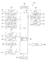
도 1은 본 발명의 일 실시예와 관련된 이동 단말기의 블록 구성도(block diagram)이다.1 is a block diagram of a mobile terminal according to an embodiment of the present invention.
이동 단말기(100)는 무선 통신부(110), A/V(Audio/Video) 입력부(120), 사용자 입력부(130), 센싱부(140), 출력부(150), 메모리(160), 인터페이스부(170), 제어부(180) 및 전원 공급부(190) 등을 포함할 수 있다. 도 1에 도시된 구성요소들이 필수적인 것은 아니어서, 그보다 많은 구성요소들을 갖거나 그보다 적은 구성요소들을 갖는 이동 단말기가 구현될 수도 있다.The
이하, 상기 구성요소들에 대해 차례로 살펴본다.Hereinafter, the components will be described in order.
무선 통신부(110)는 이동 단말기(100)와 무선 통신 시스템 사이 또는 이동 단말기(100)와 이동 단말기(100)가 위치한 네트워크 사이의 무선 통신을 가능하게 하는 하나 이상의 모듈을 포함할 수 있다. 예를 들어, 무선 통신부(110)는 방송 수신 모듈(111), 이동통신 모듈(112), 무선 인터넷 모듈(113), 근거리 통신 모듈(114) 및 위치정보 모듈(115) 등을 포함할 수 있다.The
방송 수신 모듈(111)은 방송 채널을 통하여 외부의 방송 관리 서버로부터 방송 신호 및/또는 방송 관련된 정보를 수신한다. The
방송 채널은 위성 채널, 지상파 채널을 포함할 수 있다. 상기 방송 관리 서버는, 방송 신호 및/또는 방송 관련 정보를 생성하여 송신하는 서버 또는 기 생성된 방송 신호 및/또는 방송 관련 정보를 제공받아 단말기에 송신하는 서버를 의미할 수 있다. 상기 방송 신호는, TV 방송 신호, 라디오 방송 신호, 데이터 방송 신호를 포함할 뿐만 아니라, TV 방송 신호 또는 라디오 방송 신호에 데이터 방송 신 호가 결합한 형태의 방송 신호도 포함할 수 있다. The broadcast channel may include a satellite channel and a terrestrial channel. The broadcast management server may refer to a server for generating and transmitting broadcast signals and / or broadcast related information, or a server for receiving broadcast signals and / or broadcast related information generated by the broadcast management server and transmitting the generated broadcast signals and / or broadcast related information. The broadcast signal may include a TV broadcast signal, a radio broadcast signal, a data broadcast signal, and a broadcast signal in which a data broadcast signal is combined with a TV broadcast signal or a radio broadcast signal.
방송 관련 정보는, 방송 채널, 방송 프로그램 또는 방송 서비스 제공자에 관련한 정보를 의미할 수 있다. 상기 방송 관련 정보는, 이동통신망을 통하여도 제공될 수 있다. 이러한 경우에는 상기 이동통신 모듈(112)에 의해 수신될 수 있다.The broadcast-related information may mean information related to a broadcast channel, a broadcast program, or a broadcast service provider. The broadcast-related information may also be provided through a mobile communication network. In this case, it may be received by the
방송 관련 정보는 다양한 형태로 존재할 수 있다. 예를 들어, DMB(Digital Multimedia Broadcasting)의 EPG(Electronic Program Guide) 또는 DVB-H(Digital Video Broadcast-Handheld)의 ESG(Electronic Service Guide) 등의 형태로 존재할 수 있다.Broadcast-related information can exist in various forms. For example, an EPG (Electronic Program Guide) of DMB (Digital Multimedia Broadcasting) or an ESG (Electronic Service Guide) of Digital Video Broadcast-Handheld (DVB-H).
방송 수신 모듈(111)은, 예를 들어, DMB-T(Digital Multimedia Broadcasting-Terrestrial), DMB-S(Digital Multimedia Broadcasting-Satellite), MediaFLO(Media Forward Link Only), DVB-H(Digital Video Broadcast-Handheld), ISDB-T(Integrated Services Digital Broadcast-Terrestrial) 등의 디지털 방송 시스템을 이용하여 디지털 방송 신호를 수신할 수 있다. 물론, 상기 방송 수신 모듈(111)은, 상술한 디지털 방송 시스템뿐만 아니라 다른 방송 시스템에 적합하도록 구성될 수도 있다.The
방송 수신 모듈(111)을 통해 수신된 방송 신호 및/또는 방송 관련 정보는 메모리(160)에 저장될 수 있다.The broadcast signal and / or broadcast related information received through the
이동통신 모듈(112)은, 이동 통신망 상에서 기지국, 외부의 단말, 서버 중 적어도 하나와 무선 신호를 송수신한다. 상기 무선 신호는, 음성 호 신호, 화상 통화 호 신호 또는 문자/멀티미디어 메시지 송수신에 따른 다양한 형태의 데이터를 포함할 수 있다. The
무선 인터넷 모듈(113)은 무선 인터넷 접속을 위한 모듈을 말하는 것으로, 이동 단말기(100)에 내장되거나 외장될 수 있다. 무선 인터넷 기술로는 WLAN(Wireless LAN)(Wi-Fi), Wibro(Wireless broadband), Wimax(World Interoperability for Microwave Access), HSDPA(High Speed Downlink Packet Access) 등이 이용될 수 있다. The
근거리 통신 모듈(114)은 근거리 통신을 위한 모듈을 말한다. 근거리 통신(short range communication) 기술로 블루투스(Bluetooth), RFID(Radio Frequency Identification), 적외선 통신(IrDA, infrared Data Association), UWB(Ultra Wideband), ZigBee 등이 이용될 수 있다.The short-
위치정보 모듈(115)은 이동 단말기의 위치를 획득하기 위한 모듈로서, 그의 대표적인 예로는 GPS(Global Position System) 모듈이 있다.The
도 1을 참조하면, A/V(Audio/Video) 입력부(120)는 오디오 신호 또는 비디오 신호 입력을 위한 것으로, 이에는 카메라(121)와 마이크(122) 등이 포함될 수 있다. 카메라(121)는 화상 통화모드 또는 촬영 모드에서 이미지 센서에 의해 얻어지는 정지영상 또는 동영상 등의 화상 프레임을 처리한다. 처리된 화상 프레임은 디스플레이부(151)에 표시될 수 있다.Referring to FIG. 1, an A / V (Audio / Video)
카메라(121)에서 처리된 화상 프레임은 메모리(160)에 저장되거나 무선 통신부(110)를 통하여 외부로 전송될 수 있다. 카메라(121)는 사용 환경에 따라 2개 이상이 구비될 수도 있다.The image frame processed by the
마이크(122)는 통화모드 또는 녹음모드, 음성인식 모드 등에서 마이크로폰(Microphone)에 의해 외부의 음향 신호를 입력받아 전기적인 음성 데이터로 처리한다. 처리된 음성 데이터는 통화 모드인 경우 이동통신 모듈(112)을 통하여 이동통신 기지국으로 송신 가능한 형태로 변환되어 출력될 수 있다. 마이크(122)에는 외부의 음향 신호를 입력받는 과정에서 발생되는 잡음(noise)을 제거하기 위한 다양한 잡음 제거 알고리즘이 구현될 수 있다.The
사용자 입력부(130)는 사용자가 단말기의 동작 제어를 위한 입력 데이터를 발생시킨다. 사용자 입력부(130)는 키 패드(key pad), 돔 스위치 (dome switch), 터치 패드(정압/정전), 조그 휠, 조그 스위치 등으로 구성될 수 있다. The
센싱부(140)는 이동 단말기(100)의 개폐 상태, 이동 단말기(100)의 위치, 사용자 접촉 유무, 이동 단말기의 방위, 이동 단말기의 가속/감속 등과 같이 이동 단말기(100)의 현 상태를 감지하여 이동 단말기(100)의 동작을 제어하기 위한 센싱 신호를 발생시킨다. 예를 들어 이동 단말기(100)가 슬라이드 폰 형태인 경우 슬라이드 폰의 개폐 여부를 센싱할 수 있다. 또한, 전원 공급부(190)의 전원 공급 여부, 인터페이스부(170)의 외부 기기 결합 여부 등을 센싱할 수도 있다. 한편, 상기 센싱부(140)는 근접 센서(141)를 포함할 수 있다. The
출력부(150)는 시각, 청각 또는 촉각 등과 관련된 출력을 발생시키기 위한 것으로, 이에는 디스플레이부(151), 음향 출력 모듈(152), 알람부(153), 및 햅틱 모듈(154) 등이 포함될 수 있다.The
디스플레이부(151)는 이동 단말기(100)에서 처리되는 정보를 표시(출력)한 다. 예를 들어, 이동 단말기가 통화 모드인 경우 통화와 관련된 UI(User Interface) 또는 GUI(Graphic User Interface)를 표시한다. 이동 단말기(100)가 화상 통화 모드 또는 촬영 모드인 경우에는 촬영 또는/및 수신된 영상 또는 UI, GUI를 표시한다.The
디스플레이부(151)는 액정 디스플레이(liquid crystal display, LCD), 박막 트랜지스터 액정 디스플레이(thin film transistor-liquid crystal display, TFT LCD), 유기 발광 다이오드(organic light-emitting diode, OLED), 플렉시블 디스플레이(flexible display), 3차원 디스플레이(3D display) 중에서 적어도 하나를 포함할 수 있다.The
이들 중 일부 디스플레이는 그를 통해 외부를 볼 수 있도록 투명형 또는 광투과형으로 구성될 수 있다. 이는 투명 디스플레이라 호칭될 수 있는데, 상기 투명 디스플레이의 대표적인 예로는 TOLED(Transparant OLED) 등이 있다. 디스플레이부(151)의 후방 구조 또한 광 투과형 구조로 구성될 수 있다. 이러한 구조에 의하여, 사용자는 단말기 바디의 디스플레이부(151)가 차지하는 영역을 통해 단말기 바디의 후방에 위치한 사물을 볼 수 있다.Some of these displays may be transparent or light transmissive so that they can be seen through. This can be referred to as a transparent display, and a typical example of the transparent display is TOLED (Transparent OLED) and the like. The rear structure of the
이동 단말기(100)의 구현 형태에 따라 디스플레이부(151)이 2개 이상 존재할 수 있다. 예를 들어, 이동 단말기(100)에는 복수의 디스플레이부들이 하나의 면에 이격되거나 일체로 배치될 수 있고, 또한 서로 다른 면에 각각 배치될 수도 있다. There may be two or
디스플레이부(151)와 터치 동작을 감지하는 센서(이하, '터치 센서'라 함)가 상호 레이어 구조를 이루는 경우(이하, '터치 스크린'이라 함)에, 디스플레이 부(151)는 출력 장치 이외에 입력 장치로도 사용될 수 있다. 터치 감지부는, 예를 들어, 터치 필름, 터치 시트, 터치 패드 등의 형태를 가질 수 있다.(Hereinafter, referred to as a 'touch screen') in which a
터치 감지부는 디스플레이부(151)의 특정 부위에 가해진 압력 또는 디스플레이부(151)의 특정 부위에 발생하는 정전 용량 등의 변화를 전기적인 입력신호로 변환하도록 구성될 수 있다. 터치 감지부는 터치 되는 위치 및 면적뿐만 아니라, 터치 시의 압력까지도 검출할 수 있도록 구성될 수 있다. The touch sensing unit may be configured to convert a change in a pressure applied to a specific portion of the
터치 감지부에 대한 터치 입력이 있는 경우, 그에 대응하는 신호(들)는 터치 제어기로 보내진다. 터치 제어기는 그 신호(들)를 처리한 다음 대응하는 데이터를 제어부(180)로 전송한다. 이로써, 제어부(180)는 디스플레이부(151)의 어느 영역이 터치 되었는지 여부 등을 알 수 있게 된다.If there is a touch input to the touch sensing part, the corresponding signal (s) is sent to the touch controller. The touch controller processes the signal (s) and transmits the corresponding data to the
도 1을 참조하면, 상기 터치스크린에 의해 감싸지는 이동 단말기의 내부 영역 또는 상기 터치 스크린의 근처에 근접 센서(141)가 배치될 수 있다. 상기 근접 센서는 소정의 검출면에 접근하는 물체, 혹은 근방에 존재하는 물체의 유무를 전자계의 힘 또는 적외선을 이용하여 기계적 접촉이 없이 검출하는 센서를 말한다. 근접 센서는 접촉식 센서보다는 그 수명이 길며 그 활용도 또한 높다. Referring to FIG. 1, a
상기 근접 센서의 예로는 투과형 광전 센서, 직접 반사형 광전 센서, 미러 반사형 광전 센서, 고주파 발진형 근접 센서, 정전용량형 근접 센서, 자기형 근접 센서, 적외선 근접 센서 등이 있다. 상기 터치스크린이 정전식인 경우에는 상기 포인터의 근접에 따른 전계의 변화로 상기 포인터의 근접을 검출하도록 구성된다. 이 경우 상기 터치 스크린(터치 센서)은 근접 센서로 분류될 수도 있다.Examples of the proximity sensor include a transmission type photoelectric sensor, a direct reflection type photoelectric sensor, a mirror reflection type photoelectric sensor, a high frequency oscillation type proximity sensor, a capacitive proximity sensor, a magnetic proximity sensor, and an infrared proximity sensor. And to detect the proximity of the pointer by the change of the electric field along the proximity of the pointer when the touch screen is electrostatic. In this case, the touch screen (touch sensor) may be classified as a proximity sensor.
이하에서는 설명의 편의를 위해, 상기 터치스크린 상에 포인터가 접촉되지 않으면서 근접되어 상기 포인터가 상기 터치스크린 상에 위치함이 인식되도록 하는 행위를 "근접 터치(proximity touch)"라고 칭하고, 상기 터치스크린 상에 포인터가 실제로 접촉되는 행위를 "접촉 터치(contact touch)"라고 칭한다. 상기 터치스크린 상에서 포인터로 근접 터치가 되는 위치라 함은, 상기 포인터가 근접 터치될 때 상기 포인터가 상기 터치스크린에 대해 수직으로 대응되는 위치를 의미한다.Hereinafter, for convenience of explanation, the act of recognizing that the pointer is positioned on the touch screen while the pointer is not in contact with the touch screen is referred to as "proximity touch & The act of actually touching the pointer on the screen is called "contact touch. &Quot; The position where the pointer is proximately touched on the touch screen means a position where the pointer is vertically corresponding to the touch screen when the pointer is touched.
근접센서는, 근접 터치와, 근접 터치 패턴(예를 들어, 근접 터치 거리, 근접 터치 방향, 근접 터치 속도, 근접 터치 시간, 근접 터치 위치, 근접 터치 이동 상태 등)을 감지한다. 상기 감지된 근접 터치 동작 및 근접 터치 패턴에 상응하는 정보는 터치 스크린상에 출력될 수 있다. The proximity sensor detects a proximity touch, a proximity touch pattern (e.g., a proximity touch distance, a proximity touch direction, a proximity touch speed, a proximity touch time, a proximity touch position, a proximity touch movement state, and the like). Information corresponding to the detected proximity touch operation and the proximity touch pattern may be output on the touch screen.
음향 출력 모듈(152)은 호신호 수신, 통화모드 또는 녹음 모드, 음성인식 모드, 방송수신 모드 등에서 무선 통신부(110)로부터 수신되거나 메모리(160)에 저장된 오디오 데이터를 출력할 수 있다. 음향 출력 모듈(152)은 이동 단말기(100)에서 수행되는 기능(예를 들어, 호신호 수신음, 메시지 수신음 등)과 관련된 음향 신호를 출력하기도 한다. 이러한 음향 출력 모듈(152)에는 리시버(Receiver), 스피커(speaker), 버저(Buzzer) 등이 포함될 수 있다.The
알람부(153)는 이동 단말기(100)의 이벤트 발생을 알리기 위한 신호를 출력한다. 이동 단말기에서 발생 되는 이벤트의 예로는 호 신호 수신, 메시지 수신, 키 신호 입력, 터치 입력 등이 있다. 알람부(153)는 비디오 신호나 오디오 신호 이외에 다른 형태, 예를 들어 진동으로 이벤트 발생을 알리기 위한 신호를 출력할 수도 있다. 상기 비디오 신호나 오디오 신호는 디스플레이부(151)나 음성 출력 모듈(152)을 통해서도 출력될 수 있어서, 그들(151,152)은 알람부(153)의 일부로 분류될 수도 있다.The
햅틱 모듈(haptic module)(154)은 사용자가 느낄 수 있는 다양한 촉각 효과를 발생시킨다. 햅틱 모듈(154)이 발생시키는 촉각 효과의 대표적인 예로는 진동이 있다. 햅택 모듈(154)이 발생하는 진동의 세기와 패턴 등은 제어가능하다. 예를 들어, 서로 다른 진동을 합성하여 출력하거나 순차적으로 출력할 수도 있다. The
햅틱 모듈(154)은, 진동 외에도, 접촉 피부면에 대해 수직 운동하는 핀 배열, 분사구나 흡입구를 통한 공기의 분사력이나 흡입력, 피부 표면에 대한 스침, 전극(eletrode)의 접촉, 정전기력 등의 자극에 의한 효과와, 흡열이나 발열 가능한 소자를 이용한 냉온감 재현에 의한 효과 등 다양한 촉각 효과를 발생시킬 수 있다. In addition to the vibration, the
햅틱 모듈(154)은 직접적인 접촉을 통해 촉각 효과의 전달할 수 있을 뿐만 아니라, 사용자가 손가락이나 팔 등의 근 감각을 통해 촉각 효과를 느낄 수 있도록 구현할 수도 있다. 햅틱 모듈(154)은 이동 단말기(100)의 구성 태양에 따라 2개 이상이 구비될 수 있다.The
메모리(160)는 제어부(180)의 동작을 위한 프로그램을 저장할 수 있고, 입/출력되는 데이터들(예를 들어, 폰북, 메시지, 정지영상, 동영상 등)을 임시 저장할 수도 있다. 상기 메모리(160)는 상기 터치스크린 상의 터치 입력시 출력되는 다양한 패턴의 진동 및 음향에 관한 데이터를 저장할 수 있다.The
메모리(160)는 플래시 메모리 타입(flash memory type), 하드디스크 타 입(hard disk type), 멀티미디어 카드 마이크로 타입(multimedia card micro type), 카드 타입의 메모리(예를 들어 SD 또는 XD 메모리 등), 램(Random Access Memory, RAM), SRAM(Static Random Access Memory), 롬(Read-Only Memory, ROM), EEPROM(Electrically Erasable Programmable Read-Only Memory), PROM(Programmable Read-Only Memory), 자기 메모리, 자기 디스크, 광디스크 중 적어도 하나의 타입의 저장매체를 포함할 수 있다. 이동 단말기(100)는 인터넷(internet)상에서 상기 메모리(160)의 저장 기능을 수행하는 웹 스토리지(web storage)와 관련되어 동작할 수도 있다.The
인터페이스부(170)는 이동 단말기(100)에 연결되는 모든 외부기기와의 통로 역할을 한다. 인터페이스부(170)는 외부 기기로부터 데이터를 전송받거나, 전원을 공급받아 이동 단말기(100) 내부의 각 구성 요소에 전달하거나, 이동 단말기(100) 내부의 데이터가 외부 기기로 전송되도록 한다. 예를 들어, 유/무선 헤드셋 포트, 외부 충전기 포트, 유/무선 데이터 포트, 메모리 카드(memory card) 포트, 식별 모듈이 구비된 장치를 연결하는 포트, 오디오 I/O(Input/Output) 포트, 비디오 I/O(Input/Output) 포트, 이어폰 포트 등이 인터페이스부(170)에 포함될 수 있다. The
식별 모듈은 이동 단말기(100)의 사용 권한을 인증하기 위한 각종 정보를 저장한 칩으로서, 사용자 인증 모듈(User Identify Module, UIM), 가입자 인증 모듈(Subscriber Identify Module, SIM), 범용 사용자 인증 모듈(Universal Subscriber Identity Module, USIM) 등을 포함할 수 있다. 식별 모듈이 구비된 장치(이하 '식별 장치')는, 스마트 카드(smart card) 형식으로 제작될 수 있다. 따라 서 식별 장치는 포트를 통하여 단말기(100)와 연결될 수 있다. The identification module is a chip for storing various information for authenticating the use right of the
인터페이스부(170)는 이동단말기(100)가 외부 크래들(cradle)과 연결될 때 크래들로부터의 전원이 이동 단말기(100)에 공급되는 통로가 되거나, 사용자에 의해 크래들에서 입력되는 각종 명령 신호가 이동 단말기로 전달되는 통로가 될 수 있다. 크래들로부터 입력되는 각종 명령 신호 또는 상기 전원은 이동 단말기가 크래들에 정확히 장착되었음을 인지하기 위한 신호로 동작될 수도 있다.The
제어부(controller, 180)는 통상적으로 이동 단말기의 전반적인 동작을 제어한다. 예를 들어 음성 통화, 데이터 통신, 화상 통화 등을 위한 관련된 제어 및 처리를 수행한다. 제어부(180)는 멀티 미디어 재생을 위한 멀티미디어 모듈(181)을 구비할 수도 있다. 멀티미디어 모듈(181)은 제어부(180) 내에 구현될 수도 있고, 제어부(180)와 별도로 구현될 수도 있다.The
제어부(180)는 상기 터치스크린 상에서 행해지는 필기 입력 또는 그림 그리기 입력을 각각 문자 및 이미지로 인식할 수 있는 패턴 인식 처리를 행할 수 있다. The
전원 공급부(190)는 제어부(180)의 제어에 의해 외부의 전원, 내부의 전원을 인가받아 각 구성요소들의 동작에 필요한 전원을 공급한다.The
여기에 설명되는 다양한 실시예는 예를 들어, 소프트웨어, 하드웨어 또는 이들의 조합된 것을 이용하여 컴퓨터 또는 이와 유사한 장치로 읽을 수 있는 기록매체 내에서 구현될 수 있다.The various embodiments described herein may be embodied in a recording medium readable by a computer or similar device using, for example, software, hardware, or a combination thereof.
하드웨어적인 구현에 의하면, 여기에 설명되는 실시예는 ASICs (application specific integrated circuits), DSPs (digital signal processors), DSPDs (digital signal processing devices), PLDs (programmable logic devices), FPGAs (field programmable gate arrays, 프로세서(processors), 제어기(controllers), 마이크로 컨트롤러(micro-controllers), 마이크로 프로세서(microprocessors), 기타 기능 수행을 위한 전기적인 유닛 중 적어도 하나를 이용하여 구현될 수 있다. 일부의 경우에 본 명세서에서 설명되는 실시예들이 제어부(180) 자체로 구현될 수 있다.According to a hardware implementation, the embodiments described herein may be implemented as application specific integrated circuits (ASICs), digital signal processors (DSPs), digital signal processing devices (DSPDs), programmable logic devices (PLDs), field programmable gate arrays May be implemented using at least one of a processor, controllers, micro-controllers, microprocessors, and other electronic units for performing other functions. In some cases, The embodiments described may be implemented by the
소프트웨어적인 구현에 의하면, 본 명세서에서 설명되는 절차 및 기능과 같은 실시예들은 별도의 소프트웨어 모듈들로 구현될 수 있다. 상기 소프트웨어 모듈들 각각은 본 명세서에서 설명되는 하나 이상의 기능 및 작동을 수행할 수 있다. 적절한 프로그램 언어로 쓰여진 소프트웨어 어플리케이션으로 소프트웨어 코드가 구현될 수 있다. 상기 소프트웨어 코드는 메모리(160)에 저장되고, 제어부(180)에 의해 실행될 수 있다.According to a software implementation, embodiments such as the procedures and functions described herein may be implemented with separate software modules. Each of the software modules may perform one or more of the functions and operations described herein. Software code can be implemented in a software application written in a suitable programming language. The software code is stored in the
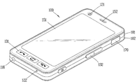
도 2a는 본 발명과 관련된 이동 단말기 또는 휴대 단말기의 일 예를 전면에서 바라본 사시도이다.2A is a perspective view of an example of a mobile terminal or a mobile terminal according to the present invention.
개시된 이동 단말기(100)는 바 형태의 단말기 바디를 구비하고 있다. 다만, 본 발명은 여기에 한정되지 않고, 2 이상의 바디들이 상대 이동 가능하게 결합되는 슬라이드 타입, 폴더 타입, 스윙 타입, 스위블 타입 등 다양한 구조에 적용이 가능하다. The disclosed
단말기 바디는 외관을 이루는 케이스(케이싱, 하우징, 커버 등)를 포함한다. 본 실시예에서, 케이스는 프론트 케이스(101)와 리어 케이스(102)로 구분될 수 있 다. 프론트 케이스(101)와 리어 케이스(102)의 사이에 형성된 공간에는 각종 전자부품들이 내장된다. 프론트 케이스(101)와 리어 케이스(102) 사이에는 적어도 하나의 중간 케이스가 추가로 배치될 수도 있다.The terminal body includes a case (a casing, a housing, a cover, and the like) which forms an appearance. In this embodiment, the case may be divided into a
케이스들은 합성수지를 사출하여 형성되거나 금속 재질, 예를 들어 스테인레스 스틸(STS) 또는 티타늄(Ti) 등과 같은 금속 재질을 갖도록 형성될 수도 있다.The cases may be formed by injection molding a synthetic resin or may be formed to have a metal material such as stainless steel (STS) or titanium (Ti) or the like.
단말기 바디, 주로 프론트 케이스(101)에는 디스플레이부(151), 음향출력부(152), 카메라(121), 사용자 입력부(130/131,132), 마이크(122), 인터페이스(170) 등이 배치될 수 있다.The
디스플레이부(151)는 프론트 케이스(101)의 주면의 대부분을 차지한다. 디스플레이부(151)의 양단부 중 일 단부에 인접한 영역에는 음향출력부(151)와 카메라(121)가 배치되고, 다른 단부에 인접한 영역에는 사용자 입력부(131)와 마이크(122)가 배치된다. 사용자 입력부(132)와 인터페이스(170) 등은 프론트 케이스(101) 및 리어 케이스(102)의 측면들에 배치될 수 있다.The
사용자 입력부(130)는 이동 단말기(100)의 동작을 제어하기 위한 명령을 입력받기 위해 조작되는 것으로서, 복수의 조작 유닛들(131,132)을 포함할 수 있다. 조작 유닛들(131,132)은 조작부(manipulating portion)로도 통칭 될 수 있으며, 사용자가 촉각 적인 느낌을 가면서 조작하게 되는 방식(tactile manner)이라면 어떤 방식이든 채용될 수 있다.The
제1 또는 제2조작 유닛들(131, 132)에 의하여 입력되는 내용은 다양하게 설정될 수 있다. 예를 들어, 제1 조작 유닛(131)은 시작, 종료, 스크롤 등과 같은 명 령을 입력받고, 제2 조작 유닛(132)은 음향출력부(152)에서 출력되는 음향의 크기 조절 또는 디스플레이부(151)의 터치 인식 모드로의 전환 등과 같은 명령을 입력받을 수 있다.The contents inputted by the first or
도 2b는 도 2a에 도시된 이동 단말기의 후면 사시도이다. 2B is a rear perspective view of the mobile terminal shown in FIG. 2A.
도 2b를 참조하면, 단말기 바디의 후면, 다시 말해서 리어 케이스(102)에는 카메라(121')가 추가로 장착될 수 있다. 카메라(121')는 카메라(121, 도 2a 참조)와 실질적으로 반대되는 촬영 방향을 가지며, 카메라(121)와 서로 다른 화소를 가지는 카메라일 수 있다. Referring to FIG. 2B, a camera 121 'may be further mounted on the rear surface of the terminal body, that is, the
예를 들어, 카메라(121)는 화상 통화 등의 경우에 사용자의 얼굴을 촬영하여 상대방에 전송함에 무리가 없도록 저 화소를 가지며, 카메라(121')는 일반적인 피사체를 촬영하고 바로 전송하지는 않는 경우가 많기에 고 화소를 가지는 것이 바람직하다. 카메라(121,121')는 회전 또는 팝업(pop-up) 가능하게 단말기 바디에 설치될 수도 있다.For example, the
카메라(121')에 인접하게는 플래쉬(123)와 거울(124)이 추가로 배치된다. 플래쉬(123)는 카메라(121')로 피사체를 촬영하는 경우에 피사체를 향해 빛을 비추게 된다. 거울(124)은 사용자가 카메라(121')를 이용하여 자신을 촬영(셀프 촬영)하고자 하는 경우에, 사용자 자신의 얼굴 등을 비춰볼 수 있게 한다.A
단말기 바디의 후면에는 음향 출력부(152')가 추가로 배치될 수도 있다. 음향 출력부(152')는 음향 출력부(152, 도 2a 참조)와 함께 스테레오 기능을 구현할 수 있으며, 통화시 스피커폰 모드의 구현을 위하여 사용될 수도 있다.An acoustic output 152 'may be additionally disposed on the rear surface of the terminal body. The sound output unit 152 'may implement the stereo function together with the sound output unit 152 (see FIG. 2A), and may be used for the implementation of the speakerphone mode during a call.
단말기 바디의 측면에는 통화 등을 위한 안테나 외에 방송신호 수신용 안테나(116)가 추가적으로 배치될 수 있다. 방송수신모듈(111, 도 1 참조)의 일부를 이루는 안테나(116)는 단말기 바디에서 인출 가능하게 설치될 수 있다.In addition to the antenna for talking and the like, a broadcast
단말기 바디에는 이동 단말기(100)에 전원을 공급하기 위한 전원공급부(190)가 장착된다. 전원공급부(190)는 단말기 바디에 내장되거나, 단말기 바디의 외부에서 직접 탈착될 수 있게 구성될 수 있다.A
도 3은 본 발명의 일실시예와 관련된 이동 단말기의 분해 사시도이고, 도 4는 도 3의 Ⅳ-Ⅳ 라인을 따르는 윈도우의 단면도이다.FIG. 3 is an exploded perspective view of a mobile terminal according to an embodiment of the present invention, and FIG. 4 is a sectional view of a window according to line IV-IV in FIG.
도 3을 참조하면, 프론트 게이스(101)에는 윈도우 장착부(103)가 형성된다. 윈도우 장착부(103)에는 투광성 재질의 윈도우(210)가 장착되며, 윈도우(210)는 윈도우 장착부(103)에 대응되는 플레이트 형태로 형성될 수 있다.Referring to FIG. 3, a
단말기 바디의 내부에는 인쇄회로기판(240,Printed Circuit Board)이 장착되며, 인쇄회로기판(240)에는 이동 단말기의 기능들을 동작시키기 위한 복수의 전자부품들이 실장된다. A printed circuit board (PCB) 240 is mounted inside the terminal body, and a plurality of electronic components for operating the functions of the mobile terminal are mounted on the
인쇄회로기판(240)에는 디스플레이 모듈(151), 음향출력모듈(152), 카메라(151), 및 윈도우(210)와의 전기적 연결을 위한 커넥터(232) 등이 장착될 수 있다. 그리고, 인쇄회로기판의 일측에는 내장 안테나(241)가 장착될 수 있다.The printed
윈도우(210)는 디스플레이 모듈(151)의 시각 정보가 출력되는 영역이 투광성으로 형성될 수 있다. 그리고, 투광성 영역을 한정하는 나머지 영역은 내부의 장착부품을 가릴 수 있도록 불투광성으로 형성될 수 있다.The
불투광성 영역에는 음향출력모듈(152)에서 출력되는 음향을 관통시키는 음향출력홀(152a)과, 카메라(121)로 촬영정보를 통과시키기 위한 카메라 홀(121a), 및 앞서 설명한 제1조작유닛(131) 등이 구비될 수 있다. 여기서, 본 실시예에 의한 제1조작유닛(131)은 터치 조작에 의해 정보를 입력하는 터치키의 형태를 갖는다.In the opaque area, an
도 4를 참조하면, 윈도우(210)의 일면(210)에는 윈도우(210)에 가해지는 터치를 감지하는 터치시트(220)가 부착된다. 본 실시예에 의하면 터치시트(220)는 윈도우(210)의 후면에 부착된다. 터치시트(220)는 투명한 접착 필름 또는 접착제에 의하여 윈도우(210)에 부착될 수 있다.Referring to FIG. 4, a
터치시트(220)에는 단말기 바디와의 전기적 연결을 위한 연성회로기판(230,Flexible Printed Circuit Board)이 구비된다. 연성회로기판(230)은 변형 가능한 필름 형태로 형성되며, 그 일면에는 회로패턴들이 형성된다.The
연성회로기판(230)는 터치시트(220)의 일단에 부착될 수 있으며, 내장 안테나(241)의 장착 위치의 반대편에 부착되는 것이 바람직하다. 이는 연성회로기판(230)에서 발생하는 전기적 신호가 내장 안테나(241)의 동작에 영향을 미치는 것을 최소화하기 위함이다.The
터치시트(220)와 연성회로기판(230)에는 전기적 연결을 위한 커넥팅부(223,233)가 각각 형성된다. 커넥팅부(223,233)는 도전성 재질의 패드 형태로 형성되며, 터치시트(220)와 연성회로기판(230)에 스퍼터링(sputtering)에 의해 형성될 수 있다. Connecting
커넥팅부(223,233)는 접착필름에 의하여 서로 접착될 수 있다. 여기서, 접착 필름은 이방전도성 필름((ACF: An-isotropic Conductive Film)의 형태를 가질 수 있다. 이방전도성 필름(ACF)은 경화가 가능한 접착 성분에 도전 입자를 분산시킨 후 이를 필름화한 것으로서, 이를 커넥팅부(223,233)의 사이에 위치시킨 상태에서 압착하면 Z방향으로는 도전 입자에 의해 전류가 흐르고, 다른 방향으로는 전류가 흐르지 않아 커넥팅부(223,233) 사이의 회로를 연결한다.The connecting
이하의 설명에서는 설명의 편의상 구성요소의 명칭을 명확히 구분하기 위하여 터치시트(220)에 형성된 것을 커넥팅 패드(223)라 지칭하고, 연성회로기판(230)에 형성된 것을 커넥팅부(233)라 지칭하기로 한다. In the following description, for the sake of descriptive convenience, the components formed on the
연성회로기판(230)의 단부에는 인쇄회로기판(240)의 커넥터(232)와의 연결을 위한 커넥터(231)가 장착된다.A
도 5a 및 5b는 본 발명의 일실시예와 관련된 터치시트의 평면도와 연성회로기판의 평면도이다. 그리고, 도 6은 연성회로기판이 터치 시트에 부착된 모습을 나타내는 평면도이다.5A and 5B are a plan view of a touch sheet and a plan view of a flexible circuit board according to an embodiment of the present invention. 6 is a plan view showing a state in which the flexible circuit board is attached to the touch sheet.
도 5a를 참조하면, 터치 시트(220)에는 제1터치영역(Ⅰ)과, 제2터치영역(Ⅱ)이 구비된다. Referring to FIG. 5A, the
본 실시예에 따르면, 제1터치영역(Ⅰ)과 제2터치영역(Ⅱ)은은 디스플레이 모듈(151)의 출력 영역과 제1조작유닛(131)에 대응되는 형태를 갖는다. The first touch area I and the second touch area II have a shape corresponding to the output area of the
제1터치영역(Ⅰ)에는 윈도우(210)의 투광성 영역에 가해진 터치를 감지하는 도전 패턴들이 복수로 형성된다. 도전패턴들은 도 5a의 X축 방향을 따르는 터치 위치를 감지하는 X축 패턴(251)과, Y축 방향을 따르는 터치 위치를 감지하는 Y축 패턴(미도시)를 포함할 수 있다. 여기서, X축 패턴(251)과 Y축 패턴은 서로 레이어를 이루도록 형성될 수 있다. 제1터치영역(Ⅰ)에 형성된 도전 패턴의 위치에 터치가 가해지면, 도전패턴에 형성된 정전 용량에 변화에 의하여 터치 위치가 감지될 수 있다.In the first touch region I, a plurality of conductive patterns for sensing a touch applied to the transmissive region of the
제2터치영역(Ⅱ)의 도전패턴들은 복수의 개소에 떨어져 위치하는 터치키의 형태를 가질 수 있다. 제2터치영역(Ⅱ)의 도전패턴은 윈도우의 제1조작유닛(131)에 터치가 가해짐에 따라 그 터치 유무가 감지될 수 있도록 구성된다.The conductive patterns of the second touch region II may have the form of a touch key located at a plurality of locations. The conductive pattern of the second touch region II is configured such that the presence or absence of the touch can be sensed as the touch is applied to the
제1 및 제2터치영역(Ⅰ,Ⅱ)의 도전패턴들은 투명한 재질의 도전성 물질, 예를 들어 ITO(인듐 주석 산화물)이 비도전성을 갖는 터치시트(220) 상에 스퍼터링(sputtering)됨에 의해 형성될 수 있다.The conductive patterns of the first and second touch regions I and II are formed by sputtering a transparent conductive material such as ITO (indium tin oxide) on the
터치시트(220)는 제1터치영역(Ⅰ)에 연결되는 복수의 연결라인들(252,253)이 형성된다. 연결라인들(252,253) 중 일부 연결라인들(252)은 X축 패턴(251)과 연결되고, 나머지 연결라인들(253)은 Y축 패턴과 연결될 수 있다. 연결라인들((252,253))은 도전성 물질(예를 들어, 은)로 형성될 수 있으며, 스퍼터링에 의하여 터치 시트(320)에 증착될 수 있다.The
터치 시트(220)의 단부에는 연결라인들(252,253)과 연성회로기판(230)을 연결하기 위한 제1커넥팅 패드(254)가 형성된다.A first connecting
여기서, X축 패턴(251)과 연결된 연결라인들(252)은 터치시트(220)의 가장자리 영역을 경유하여 제1커넥팅 패드(254)에 연결된다. 여기서, X축 패턴(251)과 연결된 연결라인들(252)은 터치시트(220)의 양측 가장자리에 배치될 수 있으며, 이하 에서는 이들을 제1연결라인들(252)이라 지칭하기로 한다.Here, the
제2터치영역(Ⅱ)의 도전패턴들 또한 연결라인(254)에 의해 연결되며, 연결라인(254)의 단부에는 제2커넥팅 패드(256)가 형성된다. 여기서, 제2커넥팅 패드(256)는 제2터치영역(Ⅱ)에 인접한 위치에 형성된다.The conductive patterns of the second touch region II are also connected by the
도 5b를 참조하면, 연성회로기판(230)은 제1회로기판부(261)와, 제2회로기판부(262), 및 라인 집합부(263)를 포함할 수 있다.5B, the
제1회로기판부(261)에는 제1터치영역(Ⅰ)에 연결된 연결라인들(252,253)과의 연결을 위한 제1커넥팅부(264)가 구비된다. 제1커넥팅부(264)는 터치시트(220)의 제1커넥팅 패드(254)와 부착된다.The first
제2회로기판부(262)는 제1회로기판부(261)에서 일측으로 연장되도록 형성된다. 제2회로기판부(262)에는 제2터치영역(Ⅱ)에 연결된 연결라인들(255)와의 연결을 위한 제2커넥팅부(266)이 구비된다. 제2커넥팅부(266)는 터치시트(220)의 제2커넥팅 패드(256)와 부착된다. 제2회로기판부(262)에는 제2커넥팅부(266)로부터 라인 집합부(263)까지 연장되는 제2연결라인(265)이 형성된다.The second
제1 및 제2커넥팅부(264,266)는 터치시트(220)와 마주하는 면, 즉, 연성회로기판(230)의 후면에 형성되나, 도 5b 및 5c에서는 설명의 편의상 실선으로 나타내었다.The first and second connecting
라인 집합부(263)는 제1커넥팅부(264)에서 연결되는 라인들(266)과 제2커넥팅부(266)에서 연결되는 라인들(265, 제2연결라인)을 집합된다. 라인 집합부(273)의 일측에는 제1 및 제2터치영역(Ⅰ,Ⅱ)에서 감지된 터치정보를 처리하는 터치정보 처리부(270)가 구비된다. 터치정보 처리부(270)는 제1 및 제2커넥팅부(264,266)에 연결되는 라인들(266,265)로부터 터치 정보를 입력받아 터치 정보를 처리한다.The
도 6은 터치시트(220)와 연성회로기판(230)이 서로 부착된 모습을 나타내고 있다.6 shows a state where the
제1회로기판부(261)는 터치시트(220)의 제1모서리(221), 즉 제1커넥팅 패드(254)가 배열된 방향을 따라 배치된다. The first
제2회로기판부(262)는 제1모서리(221)와 인접한 제2모서리(222)를 따라 배치된다. 터치시트(220)가 직사각형 형태로 형성된 경우, 제2회로기판부(262)는 제1회로기판부(261)와 직각 방향으로 연장될 수 있다.The second
제2회로기판부(262)는 제1연결라인들(252)의 적어도 일부와 중첩되게 배치된다. 터치시트(220)의 가장자리 영역, 즉 제2회로기판부(262)와 제1연결라인(252)이 위치한 영역은 윈도우(210)의 불투광성 영역에 의하여 가려질 수 있다.The second
본 실시예에 따르면, 제1터치영역(Ⅰ)에 연결된 연결라인들(252,253)은 연성회로기판(230)의 제1커넥팅부(264)를 통하여 라인 집합부(264)에서 집합된다. 그리고, 연성회로기판(230)의 제2회로기판부(252)는 제2터치영역(Ⅱ)과 연결된 제2커넥팅부로부터 라인 집합부(264)까지 연장되어 연결된다. 즉, 라인 집합부(264)에서 제1터치영역(Ⅰ)과 제2터치영역(Ⅱ)에 연결된 라인들이 집합되는 것이다.The connection lines 252 and 253 connected to the first touch region I are collected at the
제1터치영역(Ⅰ)에서 발생한 터치 신호는 터치시트(22에 형성된 연결라인들(252,253)을 통하여 라인 집합부(264)까지 전달된다. 그리고, 제2터치영역(Ⅱ)에서 발생한 터치신호는 연성회로기판(230)의 제2연결라인(262)를 통하여 라인 집합 부(264)까지 전달된다.The touch signal generated in the first touch area I is transmitted to the line set
이와 같이, 터치 신호들의 집합 위치까지의 신호 전달 경로를 터치시트(220)의 연결라인들(252,253)과 연성회로기판(230)의 제2회로기판부(262)로 이분화함으로써, 제1연결라인들(252)이 위치되는 영역의 폭(W1)을 줄일 수 있다. 이에 따라, 디스플레이(151)에 대응되는 제1터치영역(Ⅰ)의 폭을 증가시킬 수 있다.By thus differentiating the signal transmission path up to the collective position of the touch signals into the
아울러, 윈도우(210)의 불투광성 영역의 내측 부분에 연성회로기판(230)을 제1연결라인들(252)과 중첩되게 배치함으로써, 공간 활용의 효율성을 증가시킬 수 있다. In addition, the efficiency of space utilization can be increased by disposing the
본 실시예에서는 제1터치영역(Ⅰ)에 연결되는 연결라인들(252,253)의 최종 집합 위치가 연성회로기판(230){즉, 라인 집합부(263)}에 위치하는 것을 기초로 설명하였다. The final assembly position of the
그러나, 본 발명은 제1터치영역(Ⅰ)에 연결되는 연결라인들(252,253)이 적어도 하나의 위치에서 집합되고, 제2터치영역(Ⅱ)에 연결되는 연성회로기판(230)이 연결라인들(252,253)의 집합 위치까지 연장되는 구성을 통하여 제1 및 제2터치영역(Ⅰ,Ⅱ)으로부터 터치 신호가 전달되는 경로를 이원화시킬 수 있는 구성이라면 어떠한 구성으로도 변형 실시될 수 있다. 이러한 경우에도 연성회로기판(230)은 제1연결라인(252)의 적어도 일부와 중첩되도록 배치되는 것이 바람직하다 할 것이다.However, according to the present invention, the
도 7a 및 7b는 본 발명의 다른 실시예와 관련된 터치시트의 평면도와 연성회로기판의 평면도이다. 그리고, 도 8은 도 7a 및 7b의 연성회로기판과 터치시트가 부착된 모습을 보이는 평면도이다. 이들 도면에서는 앞선 실시예와 동일한 구성에 대해서는 유사한 도면부호를 부여하였다.7A and 7B are a plan view of a touch sheet and a plan view of a flexible circuit board according to another embodiment of the present invention. 8 is a plan view showing a state in which the flexible circuit board and the touch sheet of FIGS. 7A and 7B are attached. In these drawings, the same reference numerals are assigned to the same components as those of the previous embodiment.
본 실시예와 관련된 터치시트(320) 또한 제1 및 제2터치영역(Ⅰ,Ⅱ)을 구비한다. 본 실시예에 의한 제1터치영역(Ⅰ)은 디스플레이 모듈(151)의 면적 중 일정 면적을 차지하며, 제2터치영역(Ⅱ)은 디스플레이 모듈(151)의 면적 중 나머지 면적을 차지한다.The
도 7a는 제1터치영역(Ⅰ)이 상부에 일정 면적을 차지하고, 제2터치영역(Ⅱ)이 하부의 나머지 영역을 차지하는 것을 도시하고 있다. 그러나, 제1 및 제2터치영역(Ⅰ,Ⅱ)은 디스플레이 모듈(151)이 갖는 면적의 범위 내에서 다양하게 구현될 수 있다. 예를 들어, 제1 및 제2터치영역(Ⅰ,Ⅱ)이 교대로 배열되는 것도 가능하다 할 것이다.7A shows that the first touch area I occupies a certain area on the upper part and the second touch area II occupies the remaining area on the lower part. However, the first and second touch areas I and II can be variously implemented within the range of the area of the
터치시트(320)에는 제1터치영역(Ⅰ)과 연결되는 연결라인들(352,353)과, 이들에 연결되는 제1커넥팅 패드(354)가 형성된다. 그리고, 터치시트(320)에는 제2터치영역(Ⅱ)과 연결되는 제2커넥팅 패드(356)가 형성된다.The
연성회로기판(330)은 앞선 실시예와 마찬가지로 제1 및 제2회로기판부(361,362)와, 라인 집합부(363)를 포함한다. 제1회로기판부(361)에는 제1커넥팅 패드(354)에 부착되는 제1커넥팅부(364)가 형성되고, 제2회로기판부(362)에는 제2커넥팅 패드(356)에 부착되는 제2커넥팅부(366), 및 제2연결라인(365)가 형성된다.The
본 실시예에 의하면, 제1 및 제2터치영역(Ⅰ,Ⅱ)은 서로 떨어진 영역 뿐만 아니라 동일한 영역 내에서 구획되어 형성되는 것도 가능하다. 본 실시예는 제1 및 제2터치영역(Ⅰ,Ⅱ)을 제외하고 앞선 실시예와 동일한 구성을 갖는 바, 상세한 설 명은 앞선 설명에 갈음하기로 한다.According to the present embodiment, the first and second touch regions I and II may be formed not only apart from each other but also within the same region. The present embodiment has the same structure as the previous embodiment except for the first and second touch regions I and II, and the detailed description will be omitted from the above description.
도 9a 및 9b는 본 발명의 또 다른 실시예와 관련된터치시트의 평면도와 연성회로기판의 평면도이다. 그리고, 도 10은 도 9a 및 9b의 연성회로기판과 터치시트가 부착된 모습을 보이는 평면도이다. 본 도면들에서도 앞선 실시예와 동일 또는 유사한 구성에 대하여 유사한 도면 부호를 부여하였다.9A and 9B are a plan view of a touch sheet and a plan view of a flexible circuit board according to another embodiment of the present invention. 10 is a plan view showing a state in which the flexible circuit board and the touch sheet of FIGS. 9A and 9B are attached. In these drawings, like reference numerals are assigned to the same or similar components as those of the foregoing embodiment.
본 실시예에 의하면, 터치시트(420)에는 제1 및 제2터치영역(Ⅰ,Ⅱ)에 추가적으로 제3터치영역(Ⅲ)이 형성될 수 있다. According to the present embodiment, the
그 일예로서, 도 9a에 도시된 바와 같이 제1터치영역(Ⅰ)은 디스플레이 모듈(151)의 일정 면적을 차지하고, 제2터치영역(Ⅱ)은 디스플레이 모듈(151)의 나머지 면적을 차지할 수 있다. 그리고, 제3터치영역(Ⅲ)은 제1조작유닛(131)에 대응되는 형태를 가질 수 있다.9A, the first touch area I occupies a certain area of the
그리고, 터치시트(420)에는 제1터치영역(Ⅰ)에 연결되는 연결라인들(452,453)과, 연결라인들(452,453)에 연결되는 제1커넥팅 패드(454)가 형성된다. The
또한, 터치시트(420)에는 제2터치영역(Ⅱ)에 연결되는 제2커넥팅 패드(456), 제3터치영역(Ⅲ)에 연결라인(457)에 의하여 연결되는 제3커넥팅 패드(458)가 형성된다. 여기서, 제2커넥팅 패드(456)는 터치시트(420)의 한쪽 가장자리 영역이 형성되고, 제3커넥팅 패드(458)는 터치시트(320)의 다른 쪽 가장자리 영역에 형성된다.The
연성회로기판(430)은 앞선 실시예에 추가적으로 제3회로기판부(467)를 구비할 수 있다. 즉, 연성회로기판(430)은 제1 내지 제3회로기판부(461,462,467)과 라인 집합부(463)을 포함할 수 있다.The
제1회로기판부(461)가 터치시트(420)의 제1모서리(432)를 따라 배치되는 경우, 제2 및 제3회로기판부(462,467)는 제1모서리(421)에 인접한 모서리들을 따라 연장될 수 있다. 즉 제2회로기판부(462)는 제1모서리(421)에 인접한 제2모서리(422)를 따라 배치되고, 제3회로기판부(467)는 제1모서리(421)에 인접한 제3모서리(423)를 따라 배치된다.The second and third
제1회로기판부(461)에는 제1커넥팅 패드(454)에 부착되는 제1커넥팅부(464)가 형성되고, 제2회로기판부(462)에는 제2커넥팅 패드(456)에 부착되는 제2커넥팅부(466), 및 제2연결라인(465)가 형성된다.A first connecting
그리고, 제3회로기판부(467)에는 제3커넥팅 패드(458)과 부착되는 제3커넥팅부(469), 및 제3커넥팅부(469)에 연결되어 라인 집합부(463)에 집합되는 제3연결라인들(467)이 형성된다.The third
제2 및 제3회로기판부(462,467)은 터치시트(420) 양측 가장자리의 제1연결라인들(452)에 중첩되게 배치되어, 3개의 터치영역을 갖는 경우에도 제1연결라인들(452)이 위치한 영역의 폭을 최대한 줄일 수 있게 한다.The second and third
상기와 같이 설명된 본 발명과 관련된 이동 단말기는 상기 설명된 실시예들의 구성과 방법이 한정되게 적용될 수 있는 것이 아니라, 상기 실시예들은 다양한 변형이 이루어질 수 있도록 각 실시예들의 전부 또는 일부가 선택적으로 조합되어 구성될 수도 있다.The above-described mobile terminal according to the present invention is not limited to the configuration and method of the above-described embodiments, but the embodiments may be modified so that all or some of the embodiments are selectively And may be configured in combination.
도 1은 본 발명의 일 실시예와 관련된 이동 단말기의 블록 구성도(block diagram).1 is a block diagram of a mobile terminal according to an embodiment of the present invention.
도 2a은 본 발명의 일 실시예에 관련된 휴대 단말기의 전면 사시도.FIG. 2A is a front perspective view of a portable terminal according to an embodiment of the present invention; FIG.
도 2b는 본 발명의 일 실시예에 관련된 휴대 단말기의 후면 사시도.FIG. 2B is a rear perspective view of a portable terminal according to an embodiment of the present invention; FIG.
도 3은 본 발명의 일실시예와 관련된 이동 단말기의 분해 사시도. 3 is an exploded perspective view of a mobile terminal according to an embodiment of the present invention;
도 4는 도 3의 Ⅳ-Ⅳ 라인을 따르는 윈도우의 단면도이다.4 is a cross-sectional view of a window along the line IV-IV in Fig.
도 5a 및 5b는 본 발명의 일실시예와 관련된 터치시트의 평면도와 연성회로기판의 평면도. 5A and 5B are a top view of a touch sheet and a top view of a flexible circuit board according to an embodiment of the present invention.
도 6은 도 5a 및 5b의 연성회로기판과 터치 시트가 부착된 모습을 나타내는 평면도.6 is a plan view showing a state in which the flexible circuit board and the touch sheet of Figs. 5A and 5B are attached. Fig.
도 7a 및 7b는 본 발명의 다른 실시예와 관련된 터치시트의 평면도와 연성회로기판의 평면도. 7A and 7B are a top view of a touch sheet and a top view of a flexible circuit board according to another embodiment of the present invention.
도 8은 도 7a 및 7b의 연성회로기판과 터치시트가 부착된 모습을 보이는 평면도.8 is a plan view showing a state in which the flexible circuit board and the touch sheet of Figs. 7A and 7B are attached. Fig.
도 9a 및 9b는 본 발명의 또 다른 실시예와 관련된 터치시트의 평면도와 연성회로기판의 평면도. 9A and 9B are a top view of a touch sheet and a top view of a flexible circuit board in accordance with another embodiment of the present invention.
도 10은 도 9a 및 9b의 연성회로기판과 터치시트가 부착된 모습을 보이는 평면도.10 is a plan view showing a state in which the flexible circuit board and the touch sheet of Figs. 9A and 9B are attached. Fig.
Claims (18)
Priority Applications (1)
| Application Number | Priority Date | Filing Date | Title |
|---|---|---|---|
| KR1020090004800A KR101570373B1 (en) | 2009-01-20 | 2009-01-20 | Mobile terminal |
Applications Claiming Priority (1)
| Application Number | Priority Date | Filing Date | Title |
|---|---|---|---|
| KR1020090004800A KR101570373B1 (en) | 2009-01-20 | 2009-01-20 | Mobile terminal |
Publications (2)
| Publication Number | Publication Date |
|---|---|
| KR20100085498A KR20100085498A (en) | 2010-07-29 |
| KR101570373B1 true KR101570373B1 (en) | 2015-11-20 |
Family
ID=42644405
Family Applications (1)
| Application Number | Title | Priority Date | Filing Date |
|---|---|---|---|
| KR1020090004800A Expired - Fee Related KR101570373B1 (en) | 2009-01-20 | 2009-01-20 | Mobile terminal |
Country Status (1)
| Country | Link |
|---|---|
| KR (1) | KR101570373B1 (en) |
Cited By (1)
| Publication number | Priority date | Publication date | Assignee | Title |
|---|---|---|---|---|
| WO2017146407A1 (en) * | 2016-02-25 | 2017-08-31 | 동우화인켐 주식회사 | Electronic device having touch sensor and antenna therein |
Families Citing this family (5)
| Publication number | Priority date | Publication date | Assignee | Title |
|---|---|---|---|---|
| KR101303633B1 (en) * | 2011-06-13 | 2013-09-11 | 엘지이노텍 주식회사 | Self-Capacitance Touch window |
| EP3026820B1 (en) * | 2013-07-22 | 2019-04-24 | LG Electronics Inc. | Mobile terminal |
| KR102177901B1 (en) * | 2013-12-31 | 2020-11-12 | 엘지디스플레이 주식회사 | Display device with integrated touch screen |
| KR102187657B1 (en) * | 2014-03-04 | 2020-12-07 | 엘지이노텍 주식회사 | Touch window and display with the same |
| CN116612694A (en) * | 2023-06-27 | 2023-08-18 | 京东方科技集团股份有限公司 | Display module and display device thereof |
Citations (1)
| Publication number | Priority date | Publication date | Assignee | Title |
|---|---|---|---|---|
| CN101344831A (en) | 2008-08-27 | 2009-01-14 | 南亚塑胶工业股份有限公司 | Condenser type touching control panel reducing line impedence by FPC |
-
2009
- 2009-01-20 KR KR1020090004800A patent/KR101570373B1/en not_active Expired - Fee Related
Patent Citations (1)
| Publication number | Priority date | Publication date | Assignee | Title |
|---|---|---|---|---|
| CN101344831A (en) | 2008-08-27 | 2009-01-14 | 南亚塑胶工业股份有限公司 | Condenser type touching control panel reducing line impedence by FPC |
Cited By (1)
| Publication number | Priority date | Publication date | Assignee | Title |
|---|---|---|---|---|
| WO2017146407A1 (en) * | 2016-02-25 | 2017-08-31 | 동우화인켐 주식회사 | Electronic device having touch sensor and antenna therein |
Also Published As
| Publication number | Publication date |
|---|---|
| KR20100085498A (en) | 2010-07-29 |
Similar Documents
| Publication | Publication Date | Title |
|---|---|---|
| KR101613919B1 (en) | Mobile terminal | |
| KR101821286B1 (en) | Mobile terminal | |
| KR20150019133A (en) | Mobile terminal | |
| KR101537692B1 (en) | Mobile terminal | |
| KR101969801B1 (en) | Mobile terminal | |
| KR20130083237A (en) | Mobile terminal | |
| KR101570373B1 (en) | Mobile terminal | |
| KR20140057965A (en) | Mobile terminal | |
| KR101772074B1 (en) | Mobile terminal | |
| KR101602302B1 (en) | Mobile terminal | |
| KR101717107B1 (en) | Mobile terminal and dispaly module thereof | |
| KR101561906B1 (en) | Mobile terminal | |
| KR20130088982A (en) | Mobile terminal | |
| KR20120115018A (en) | Mobile terminal | |
| KR101804914B1 (en) | Mobile terminal | |
| KR101786545B1 (en) | Mobile terminal | |
| KR101771453B1 (en) | Mobile terminal | |
| KR20130088980A (en) | Mobile terminal | |
| KR101951415B1 (en) | Mobile terminal | |
| KR20120118821A (en) | Mobile terminal | |
| KR20130062751A (en) | Mobile terminal | |
| KR101984089B1 (en) | Mobile terminal | |
| KR101977073B1 (en) | Mobile terminal | |
| KR101667717B1 (en) | Mobile terminal | |
| KR101911247B1 (en) | Mobile terminal |
Legal Events
| Date | Code | Title | Description |
|---|---|---|---|
| PA0109 | Patent application |
St.27 status event code: A-0-1-A10-A12-nap-PA0109 |
|
| R18-X000 | Changes to party contact information recorded |
St.27 status event code: A-3-3-R10-R18-oth-X000 |
|
| R18-X000 | Changes to party contact information recorded |
St.27 status event code: A-3-3-R10-R18-oth-X000 |
|
| PG1501 | Laying open of application |
St.27 status event code: A-1-1-Q10-Q12-nap-PG1501 |
|
| A201 | Request for examination | ||
| PA0201 | Request for examination |
St.27 status event code: A-1-2-D10-D11-exm-PA0201 |
|
| D13-X000 | Search requested |
St.27 status event code: A-1-2-D10-D13-srh-X000 |
|
| D14-X000 | Search report completed |
St.27 status event code: A-1-2-D10-D14-srh-X000 |
|
| E902 | Notification of reason for refusal | ||
| PE0902 | Notice of grounds for rejection |
St.27 status event code: A-1-2-D10-D21-exm-PE0902 |
|
| E13-X000 | Pre-grant limitation requested |
St.27 status event code: A-2-3-E10-E13-lim-X000 |
|
| P11-X000 | Amendment of application requested |
St.27 status event code: A-2-2-P10-P11-nap-X000 |
|
| P13-X000 | Application amended |
St.27 status event code: A-2-2-P10-P13-nap-X000 |
|
| PN2301 | Change of applicant |
St.27 status event code: A-3-3-R10-R13-asn-PN2301 St.27 status event code: A-3-3-R10-R11-asn-PN2301 |
|
| E701 | Decision to grant or registration of patent right | ||
| PE0701 | Decision of registration |
St.27 status event code: A-1-2-D10-D22-exm-PE0701 |
|
| PR0701 | Registration of establishment |
St.27 status event code: A-2-4-F10-F11-exm-PR0701 |
|
| PR1002 | Payment of registration fee |
St.27 status event code: A-2-2-U10-U11-oth-PR1002 Fee payment year number: 1 |
|
| PG1601 | Publication of registration |
St.27 status event code: A-4-4-Q10-Q13-nap-PG1601 |
|
| LAPS | Lapse due to unpaid annual fee | ||
| PC1903 | Unpaid annual fee |
St.27 status event code: A-4-4-U10-U13-oth-PC1903 Not in force date: 20181114 Payment event data comment text: Termination Category : DEFAULT_OF_REGISTRATION_FEE |
|
| PC1903 | Unpaid annual fee |
St.27 status event code: N-4-6-H10-H13-oth-PC1903 Ip right cessation event data comment text: Termination Category : DEFAULT_OF_REGISTRATION_FEE Not in force date: 20181114 |
|
| PN2301 | Change of applicant |
St.27 status event code: A-5-5-R10-R13-asn-PN2301 St.27 status event code: A-5-5-R10-R11-asn-PN2301 |
|
| P22-X000 | Classification modified |
St.27 status event code: A-4-4-P10-P22-nap-X000 |