KR101555107B1 - Railway car vibration control device - Google Patents
Railway car vibration control device Download PDFInfo
- Publication number
- KR101555107B1 KR101555107B1 KR1020137014119A KR20137014119A KR101555107B1 KR 101555107 B1 KR101555107 B1 KR 101555107B1 KR 1020137014119 A KR1020137014119 A KR 1020137014119A KR 20137014119 A KR20137014119 A KR 20137014119A KR 101555107 B1 KR101555107 B1 KR 101555107B1
- Authority
- KR
- South Korea
- Prior art keywords
- valve
- piston
- chamber
- opening
- rod
- Prior art date
- Legal status (The legal status is an assumption and is not a legal conclusion. Google has not performed a legal analysis and makes no representation as to the accuracy of the status listed.)
- Expired - Fee Related
Links
Images


Classifications
-
- F—MECHANICAL ENGINEERING; LIGHTING; HEATING; WEAPONS; BLASTING
- F15—FLUID-PRESSURE ACTUATORS; HYDRAULICS OR PNEUMATICS IN GENERAL
- F15B—SYSTEMS ACTING BY MEANS OF FLUIDS IN GENERAL; FLUID-PRESSURE ACTUATORS, e.g. SERVOMOTORS; DETAILS OF FLUID-PRESSURE SYSTEMS, NOT OTHERWISE PROVIDED FOR
- F15B21/00—Common features of fluid actuator systems; Fluid-pressure actuator systems or details thereof, not covered by any other group of this subclass
- F15B21/04—Special measures taken in connection with the properties of the fluid
- F15B21/042—Controlling the temperature of the fluid
- F15B21/0427—Heating
-
- B—PERFORMING OPERATIONS; TRANSPORTING
- B61—RAILWAYS
- B61F—RAIL VEHICLE SUSPENSIONS, e.g. UNDERFRAMES, BOGIES OR ARRANGEMENTS OF WHEEL AXLES; RAIL VEHICLES FOR USE ON TRACKS OF DIFFERENT WIDTH; PREVENTING DERAILING OF RAIL VEHICLES; WHEEL GUARDS, OBSTRUCTION REMOVERS OR THE LIKE FOR RAIL VEHICLES
- B61F5/00—Constructional details of bogies; Connections between bogies and vehicle underframes; Arrangements or devices for adjusting or allowing self-adjustment of wheel axles or bogies when rounding curves
- B61F5/02—Arrangements permitting limited transverse relative movements between vehicle underframe or bolster and bogie; Connections between underframes and bogies
- B61F5/04—Bolster supports or mountings
- B61F5/12—Bolster supports or mountings incorporating dampers
- B61F5/127—Bolster supports or mountings incorporating dampers with fluid as a damping medium
-
- B—PERFORMING OPERATIONS; TRANSPORTING
- B61—RAILWAYS
- B61F—RAIL VEHICLE SUSPENSIONS, e.g. UNDERFRAMES, BOGIES OR ARRANGEMENTS OF WHEEL AXLES; RAIL VEHICLES FOR USE ON TRACKS OF DIFFERENT WIDTH; PREVENTING DERAILING OF RAIL VEHICLES; WHEEL GUARDS, OBSTRUCTION REMOVERS OR THE LIKE FOR RAIL VEHICLES
- B61F5/00—Constructional details of bogies; Connections between bogies and vehicle underframes; Arrangements or devices for adjusting or allowing self-adjustment of wheel axles or bogies when rounding curves
- B61F5/02—Arrangements permitting limited transverse relative movements between vehicle underframe or bolster and bogie; Connections between underframes and bogies
- B61F5/22—Guiding of the vehicle underframes with respect to the bogies
- B61F5/24—Means for damping or minimising the canting, skewing, pitching, or plunging movements of the underframes
- B61F5/245—Means for damping or minimising the canting, skewing, pitching, or plunging movements of the underframes by active damping, i.e. with means to vary the damping characteristics in accordance with track or vehicle induced reactions, especially in high speed mode
-
- F—MECHANICAL ENGINEERING; LIGHTING; HEATING; WEAPONS; BLASTING
- F15—FLUID-PRESSURE ACTUATORS; HYDRAULICS OR PNEUMATICS IN GENERAL
- F15B—SYSTEMS ACTING BY MEANS OF FLUIDS IN GENERAL; FLUID-PRESSURE ACTUATORS, e.g. SERVOMOTORS; DETAILS OF FLUID-PRESSURE SYSTEMS, NOT OTHERWISE PROVIDED FOR
- F15B21/00—Common features of fluid actuator systems; Fluid-pressure actuator systems or details thereof, not covered by any other group of this subclass
- F15B21/04—Special measures taken in connection with the properties of the fluid
-
- F—MECHANICAL ENGINEERING; LIGHTING; HEATING; WEAPONS; BLASTING
- F15—FLUID-PRESSURE ACTUATORS; HYDRAULICS OR PNEUMATICS IN GENERAL
- F15B—SYSTEMS ACTING BY MEANS OF FLUIDS IN GENERAL; FLUID-PRESSURE ACTUATORS, e.g. SERVOMOTORS; DETAILS OF FLUID-PRESSURE SYSTEMS, NOT OTHERWISE PROVIDED FOR
- F15B2211/00—Circuits for servomotor systems
- F15B2211/30—Directional control
- F15B2211/305—Directional control characterised by the type of valves
- F15B2211/30505—Non-return valves, i.e. check valves
-
- F—MECHANICAL ENGINEERING; LIGHTING; HEATING; WEAPONS; BLASTING
- F15—FLUID-PRESSURE ACTUATORS; HYDRAULICS OR PNEUMATICS IN GENERAL
- F15B—SYSTEMS ACTING BY MEANS OF FLUIDS IN GENERAL; FLUID-PRESSURE ACTUATORS, e.g. SERVOMOTORS; DETAILS OF FLUID-PRESSURE SYSTEMS, NOT OTHERWISE PROVIDED FOR
- F15B2211/00—Circuits for servomotor systems
- F15B2211/30—Directional control
- F15B2211/305—Directional control characterised by the type of valves
- F15B2211/3056—Assemblies of multiple valves
- F15B2211/30565—Assemblies of multiple valves having multiple valves for a single output member, e.g. for creating higher valve function by use of multiple valves like two 2/2-valves replacing a 5/3-valve
- F15B2211/3058—Assemblies of multiple valves having multiple valves for a single output member, e.g. for creating higher valve function by use of multiple valves like two 2/2-valves replacing a 5/3-valve having additional valves for interconnecting the fluid chambers of a double-acting actuator, e.g. for regeneration mode or for floating mode
-
- F—MECHANICAL ENGINEERING; LIGHTING; HEATING; WEAPONS; BLASTING
- F15—FLUID-PRESSURE ACTUATORS; HYDRAULICS OR PNEUMATICS IN GENERAL
- F15B—SYSTEMS ACTING BY MEANS OF FLUIDS IN GENERAL; FLUID-PRESSURE ACTUATORS, e.g. SERVOMOTORS; DETAILS OF FLUID-PRESSURE SYSTEMS, NOT OTHERWISE PROVIDED FOR
- F15B2211/00—Circuits for servomotor systems
- F15B2211/30—Directional control
- F15B2211/315—Directional control characterised by the connections of the valve or valves in the circuit
- F15B2211/31523—Directional control characterised by the connections of the valve or valves in the circuit being connected to a pressure source and an output member
- F15B2211/31529—Directional control characterised by the connections of the valve or valves in the circuit being connected to a pressure source and an output member having a single pressure source and a single output member
-
- F—MECHANICAL ENGINEERING; LIGHTING; HEATING; WEAPONS; BLASTING
- F15—FLUID-PRESSURE ACTUATORS; HYDRAULICS OR PNEUMATICS IN GENERAL
- F15B—SYSTEMS ACTING BY MEANS OF FLUIDS IN GENERAL; FLUID-PRESSURE ACTUATORS, e.g. SERVOMOTORS; DETAILS OF FLUID-PRESSURE SYSTEMS, NOT OTHERWISE PROVIDED FOR
- F15B2211/00—Circuits for servomotor systems
- F15B2211/30—Directional control
- F15B2211/315—Directional control characterised by the connections of the valve or valves in the circuit
- F15B2211/31552—Directional control characterised by the connections of the valve or valves in the circuit being connected to an output member and a return line
- F15B2211/31558—Directional control characterised by the connections of the valve or valves in the circuit being connected to an output member and a return line having a single output member
-
- F—MECHANICAL ENGINEERING; LIGHTING; HEATING; WEAPONS; BLASTING
- F15—FLUID-PRESSURE ACTUATORS; HYDRAULICS OR PNEUMATICS IN GENERAL
- F15B—SYSTEMS ACTING BY MEANS OF FLUIDS IN GENERAL; FLUID-PRESSURE ACTUATORS, e.g. SERVOMOTORS; DETAILS OF FLUID-PRESSURE SYSTEMS, NOT OTHERWISE PROVIDED FOR
- F15B2211/00—Circuits for servomotor systems
- F15B2211/50—Pressure control
- F15B2211/505—Pressure control characterised by the type of pressure control means
- F15B2211/50509—Pressure control characterised by the type of pressure control means the pressure control means controlling a pressure upstream of the pressure control means
- F15B2211/50518—Pressure control characterised by the type of pressure control means the pressure control means controlling a pressure upstream of the pressure control means using pressure relief valves
-
- F—MECHANICAL ENGINEERING; LIGHTING; HEATING; WEAPONS; BLASTING
- F15—FLUID-PRESSURE ACTUATORS; HYDRAULICS OR PNEUMATICS IN GENERAL
- F15B—SYSTEMS ACTING BY MEANS OF FLUIDS IN GENERAL; FLUID-PRESSURE ACTUATORS, e.g. SERVOMOTORS; DETAILS OF FLUID-PRESSURE SYSTEMS, NOT OTHERWISE PROVIDED FOR
- F15B2211/00—Circuits for servomotor systems
- F15B2211/50—Pressure control
- F15B2211/515—Pressure control characterised by the connections of the pressure control means in the circuit
- F15B2211/5159—Pressure control characterised by the connections of the pressure control means in the circuit being connected to an output member and a return line
-
- F—MECHANICAL ENGINEERING; LIGHTING; HEATING; WEAPONS; BLASTING
- F15—FLUID-PRESSURE ACTUATORS; HYDRAULICS OR PNEUMATICS IN GENERAL
- F15B—SYSTEMS ACTING BY MEANS OF FLUIDS IN GENERAL; FLUID-PRESSURE ACTUATORS, e.g. SERVOMOTORS; DETAILS OF FLUID-PRESSURE SYSTEMS, NOT OTHERWISE PROVIDED FOR
- F15B2211/00—Circuits for servomotor systems
- F15B2211/50—Pressure control
- F15B2211/52—Pressure control characterised by the type of actuation
- F15B2211/526—Pressure control characterised by the type of actuation electrically or electronically
-
- F—MECHANICAL ENGINEERING; LIGHTING; HEATING; WEAPONS; BLASTING
- F15—FLUID-PRESSURE ACTUATORS; HYDRAULICS OR PNEUMATICS IN GENERAL
- F15B—SYSTEMS ACTING BY MEANS OF FLUIDS IN GENERAL; FLUID-PRESSURE ACTUATORS, e.g. SERVOMOTORS; DETAILS OF FLUID-PRESSURE SYSTEMS, NOT OTHERWISE PROVIDED FOR
- F15B2211/00—Circuits for servomotor systems
- F15B2211/60—Circuit components or control therefor
- F15B2211/62—Cooling or heating means
-
- F—MECHANICAL ENGINEERING; LIGHTING; HEATING; WEAPONS; BLASTING
- F16—ENGINEERING ELEMENTS AND UNITS; GENERAL MEASURES FOR PRODUCING AND MAINTAINING EFFECTIVE FUNCTIONING OF MACHINES OR INSTALLATIONS; THERMAL INSULATION IN GENERAL
- F16F—SPRINGS; SHOCK-ABSORBERS; MEANS FOR DAMPING VIBRATION
- F16F15/00—Suppression of vibrations in systems; Means or arrangements for avoiding or reducing out-of-balance forces, e.g. due to motion
- F16F15/02—Suppression of vibrations of non-rotating, e.g. reciprocating systems; Suppression of vibrations of rotating systems by use of members not moving with the rotating systems
-
- F—MECHANICAL ENGINEERING; LIGHTING; HEATING; WEAPONS; BLASTING
- F16—ENGINEERING ELEMENTS AND UNITS; GENERAL MEASURES FOR PRODUCING AND MAINTAINING EFFECTIVE FUNCTIONING OF MACHINES OR INSTALLATIONS; THERMAL INSULATION IN GENERAL
- F16F—SPRINGS; SHOCK-ABSORBERS; MEANS FOR DAMPING VIBRATION
- F16F2222/00—Special physical effects, e.g. nature of damping effects
- F16F2222/02—Special physical effects, e.g. nature of damping effects temperature-related
Landscapes
- Engineering & Computer Science (AREA)
- Mechanical Engineering (AREA)
- General Engineering & Computer Science (AREA)
- Physics & Mathematics (AREA)
- Analytical Chemistry (AREA)
- Fluid Mechanics (AREA)
- Chemical & Material Sciences (AREA)
- Acoustics & Sound (AREA)
- Aviation & Aerospace Engineering (AREA)
- Vehicle Body Suspensions (AREA)
- Vibration Prevention Devices (AREA)
- Fluid-Pressure Circuits (AREA)
- Fluid-Damping Devices (AREA)
Abstract
철도 차량용 제진 장치(1)는 철도 차량의 대차에 연결되는 실린더(2)와, 피스톤(3)과, 피스톤(3)과 차체에 연결되는 로드(4)와, 실린더(2) 내의 로드측실(5) 및 피스톤측실(6)과, 탱크(7)와, 로드측실(5)과 피스톤측실(6)을 연통하는 제1 유로(8)의 도중에 설치한 제1 개폐 밸브(9)와, 피스톤측실(6)과 탱크(7)를 연통하는 제2 통로(10)의 도중에 설치한 제2 개폐 밸브(11)와, 로드측실(5)로 액체를 공급하는 펌프(12)를 갖는 작동기(A1, A2)를 구비하고, 기동 후이며 차체의 진동을 억제하는 통상 제어 모드로 이행하기 전에, 제1 개폐 밸브(9) 및 제2 개폐 밸브(11)를 개방하고, 펌프(12)를 구동하여 작동기(A1, A2)를 온기 운전한다.A vibration isolation device for a railway vehicle 1 includes a cylinder 2 connected to a railroad car, a piston 3, a rod 4 connected to the piston 3 and the vehicle body, A first open / close valve 9 provided in the middle of a first flow path 8 for communicating the rod side chamber 5 and the piston side chamber 6 with each other, a piston 7, a piston chamber 6, a tank 7, A second open / close valve 11 provided in the middle of a second passage 10 communicating the chamber 6 and the tank 7 and an actuator A1 having a pump 12 for supplying liquid to the rod chamber 5 The first opening / closing valve 9 and the second opening / closing valve 11 are opened and the pump 12 is driven to start the normal control mode Operate the actuators A1 and A2 in warm-up mode.
Description
본 발명은 철도 차량용 제진 장치에 관한 것이다.The present invention relates to a vibration isolation device for a railway vehicle.
철도 차량용 제진 장치는, 철도 차량의 차체와 대차 사이에 개재 장착되어, 철도 차량에 작용하는 진동으로서 차체의 진행 방향에 대하여 좌우 방향의 진동을 억제하는 것이 알려져 있다.BACKGROUND ART It is known that a vibration damping device for a railway vehicle is interposed between a vehicle body and a truck of a railway vehicle and suppresses lateral vibration in the traveling direction of the vehicle body as vibration acting on the railway vehicle.
JP2010-65797호 공보는, 철도 차량용 제진 장치를 개시하고 있다. 이 철도 차량용 제진 장치는 철도 차량의 대차 및 차체의 한쪽에 연결되는 실린더와, 해당 실린더 내에 미끄럼 이동 가능하게 삽입되는 피스톤과, 실린더 내에 삽입되어서 피스톤과 대차 및 차체의 다른 쪽에 연결되는 로드와, 실린더 내에 피스톤으로 구획된 로드측실 및 피스톤측실과, 탱크와, 로드측실과 피스톤측실을 연통하는 제1 유로의 도중에 설치한 제1 개폐 밸브와, 피스톤측실과 탱크를 연통하는 제2 통로의 도중에 설치한 제2 개폐 밸브와, 로드측실로 작동유를 공급하는 펌프와, 로드측실을 상기 탱크에 접속하는 배출 통로와, 해당 배출 통로의 도중에 설치되어 개방 밸브압을 변경 가능한 가변 릴리프 밸브를 구비한다.JP2010-65797A discloses a vibration isolation device for a railway vehicle. The vibration damping device for a railway vehicle includes a cylinder connected to one side of a railway car and a vehicle body, a piston slidably inserted in the cylinder, a rod inserted in the cylinder and connected to the other side of the piston and the vehicle body, A first opening / closing valve installed in the middle of a first passage communicating between the piston chamber and the piston chamber, and a second opening / closing valve provided in the middle of the second passage communicating the piston chamber and the tank A second opening / closing valve, a pump for supplying operating oil to the rod chamber, a discharge passage connecting the rod chamber to the tank, and a variable relief valve installed at the middle of the discharge passage to change the opening valve pressure.
이 철도 차량용 제진 장치는, 펌프, 제1 개폐 밸브, 제2 개폐 밸브 및 가변 릴리프 밸브를 구동함으로써, 신축 양쪽으로 추력을 발휘시켜, 이 추력으로 차체의 진동을 억제시킨다.The vibration damping device for a railway vehicle drives the pump, the first opening / closing valve, the second opening / closing valve, and the variable relief valve to exert thrust on both the expansion and contraction, thereby suppressing the vibration of the vehicle body with this thrust.
철도 차량이 영업 주행 중인 경우, 철도 차량용 제진 장치는 펌프를 일정 회전 속도로 구동하고, 차체의 진동 상황에 따라서, 제1 개폐 밸브, 제2 개폐 밸브 및 가변 릴리프 밸브를 적절히 구동하여 차체 진동을 억제한다. 철도 차량이 영업 주행을 끝내고, 영업 주행을 재개할 때까지, 철도 차량은 차고에 수용되지만, 그 사이 철도 차량용 제진 장치는 구동을 정지하고 있다.When the railway vehicle is in operation, the vibration suppressing device for the railway vehicle drives the pump at a constant rotation speed and appropriately drives the first opening / closing valve, the second opening / closing valve, and the variable relief valve according to the vibration condition of the vehicle body to suppress the vehicle body vibration do. The railway vehicle is accommodated in the garage until the railway vehicle finishes the business run and resumes the business run, but the stopping device for the railway vehicle is stopped in the meantime.
여기서, 철도 차량용 제진 장치는 유압을 이용하여 차체의 진동을 억제하는 추력을 얻고 있지만, 영업 주행이 종료되고나서 재개될 때까지의 동안은 구동을 정지하고 있으므로, 기동 직후는 작동기 내의 작동유의 온도가 낮다. 작동유의 온도가 낮으면, 작동유의 점도가 높고, 펌프의 회전축 주위의 마찰도 커지므로, 펌프의 토출 유량이 불안정해져, 작동기의 추력이 안정되지 않게 된다.Here, although the vibration suppressing device for a railway vehicle obtains a thrust for suppressing the vibration of the vehicle body using the hydraulic pressure, since the drive is stopped during the period from the end of the running to the restart, the temperature of the hydraulic oil in the actuator low. If the temperature of the operating oil is low, the viscosity of the working oil is high and the friction around the rotating shaft of the pump becomes large, so that the discharge flow rate of the pump becomes unstable and the thrust of the actuator becomes unstable.
또한, 작동기가 발휘하는 추력을 피드백 제어하고자 하는 경우, 철도 차량용 제진 장치의 기동 직후에서는 추력이 안정되지 않기 때문에, 추력의 편차가 커져 차체 진동을 악화시켜 버릴 가능성이 있다.Further, in the case where the thrust force exerted by the actuator is to be feedback-controlled, the thrust is not stabilized immediately after the starting of the anti-vibration device for the railway vehicle, so that the deviation of the thrust becomes large and the vehicle body vibration may be deteriorated.
본 발명의 목적은, 안정된 추력을 발휘하여 차체 진동을 효과적으로 억제할 수 있는 철도 차량용 제진 장치를 제공하는 것이다.SUMMARY OF THE INVENTION An object of the present invention is to provide a vibration damping device for a railway vehicle capable of effectively suppressing body vibration by exhibiting a stable thrust.
본 발명의 어떤 형태에 따르면, 철도 차량의 대차 및 차체의 한쪽에 연결되는 실린더와, 실린더 내에 미끄럼 이동 가능하게 삽입되는 피스톤과, 실린더 내에 삽입되어서 피스톤과 대차 및 차체의 다른 쪽에 연결되는 로드와, 실린더 내에 피스톤에 의해 구획되는 로드측실 및 피스톤측실과, 탱크와, 로드측실과 피스톤측실을 연통하는 제1 유로의 도중에 설치한 제1 개폐 밸브와, 피스톤측실과 탱크를 연통하는 제2 통로의 도중에 설치한 제2 개폐 밸브와, 로드측실로 액체를 공급하는 펌프를 갖는 작동기를 구비하고, 차체의 진동을 억제하는 철도 차량용 제진 장치로서, 기동 후이며 차체의 진동을 억제하는 통상 제어 모드로 이행하기 전에, 제1 개폐 밸브 및 제2 개폐 밸브를 개방하여, 펌프를 구동하여 작동기를 온기 운전하는 철도 차량용 제진 장치가 제공된다.According to a certain aspect of the present invention, there is provided a railway vehicle comprising: a cylinder connected to one side of a railway car and a vehicle body; a piston slidably inserted in the cylinder; a rod inserted in the cylinder and connected to the other side of the piston, A first opening / closing valve provided in the middle of a rod chamber and a piston chamber separated by a piston in the cylinder, a tank, a first passage communicating the rod chamber and the piston chamber, and a second opening / closing valve provided in the middle of the second passage communicating the piston chamber and the tank A second opening / closing valve provided in the load side chamber, and an actuator having a pump for supplying liquid to the rod side chamber, and suppressing vibration of the vehicle body, wherein the mode shifts to the normal control mode after starting and suppressing vibration of the vehicle body The vibration damping device for a railway vehicle which opens the first on-off valve and the second on-off valve and drives the pump to warm the actuator It is a ball.
본 발명은, 안정된 추력을 발휘하여 차체 진동을 효과적으로 억제할 수 있는 철도 차량용 제진 장치를 제공할 수 있다.INDUSTRIAL APPLICABILITY The present invention can provide a vibration damping device for a railway vehicle capable of effectively suppressing body vibration by exhibiting a stable thrust.
도 1은 본 발명의 실시 형태에 따른 철도 차량용 제진 장치를 탑재한 철도 차량의 단면도이다.
도 2는 본 발명의 실시 형태에 따른 철도 차량용 제진 장치의 작동기의 상세도이다.
도 3은 본 발명의 실시 형태에 따른 철도 차량용 제진 장치에 있어서의 컨트롤러의 제어 블록도이다.1 is a sectional view of a railway vehicle equipped with a vibration isolation device for a railway vehicle according to an embodiment of the present invention.
2 is a detailed view of an actuator of a vibration damping apparatus for a railway vehicle according to an embodiment of the present invention.
3 is a control block diagram of a controller in a vibration damping apparatus for a railway vehicle according to an embodiment of the present invention.
본 발명의 실시 형태, 본 발명의 이점에 대해서는, 첨부된 도면을 참조하면서 이하에 상세하게 설명한다.BRIEF DESCRIPTION OF THE DRAWINGS Embodiments of the present invention and advantages of the present invention will be described in detail below with reference to the accompanying drawings.
본 실시 형태에 있어서의 철도 차량용 제진 장치(1)는, 철도 차량의 차체(B)의 제진 장치로서 사용된다. 철도 차량용 제진 장치(1)는, 도 1에 도시한 바와 같이, 대차(W)와 차체(B) 사이에 개재 장착되는 한 쌍의 작동기(A1, A2)와, 작동기(A1, A2)를 제어하는 컨트롤러(C)를 구비한다. 작동기(A1, A2)는, 철도 차량의 차체(B)의 하방으로 늘어지는 핀(P)에 연결되어, 차체(B)와 대차(W) 사이에서 쌍을 이루어 병렬로 개재 장착된다.The
작동기(A1, A2)는 통상 제어 모드일 경우, 차체(B)의 차량 진행 방향에 대하여 수평인 가로 방향의 진동을 억제한다. 컨트롤러(C)는 통상 제어 모드일 경우, 스카이훅 제어를 행하여 작동기(A1, A2)에 추력을 발생시켜, 차체(B)의 가로 방향의 진동을 억제한다.In the normal control mode, the actuators A1 and A2 suppress lateral vibration in the vehicle body B, which is horizontal with respect to the vehicle traveling direction. When the controller C is in the normal control mode, the controller C performs sky hook control to generate thrusts in the actuators A1 and A2 to suppress the lateral vibration of the vehicle body B.
컨트롤러(C)는 통상 제어 모드일 경우, 차체(B)의 차량 진행 방향에 대하여 수평인 가로 방향의 속도를 얻어, 작동기(A1, A2)에서 발생해야 할 추력인 제진력 명령 값을 구하고, 제진력 명령 값대로의 추력을 작동기(A1, A2)에 발생시키도록 제어함으로써, 차체(B)의 가로 방향의 진동을 억제한다.In the normal control mode, the controller C obtains the velocity in the transverse direction, which is horizontal with respect to the vehicle traveling direction of the vehicle body B, to obtain the exertion force command value, which is the thrust force to be generated in the actuators A1 and A2, The lateral vibration of the vehicle body B is suppressed by controlling the actuators A1 and A2 to generate thrust as the power command value.
작동기(A1, A2)의 구체적인 구성에 대하여 설명한다. 또한, 작동기(A1, A2)는 동일한 구성이므로, 설명의 중복을 피하기 위해, 작동기(A1)에 대해서만 설명하고, 작동기(A2)에 대한 설명을 생략한다.A specific configuration of the actuators A1 and A2 will be described. Since the actuators A1 and A2 have the same configuration, only the actuator A1 is described, and the explanation of the actuator A2 is omitted in order to avoid duplication of explanation.
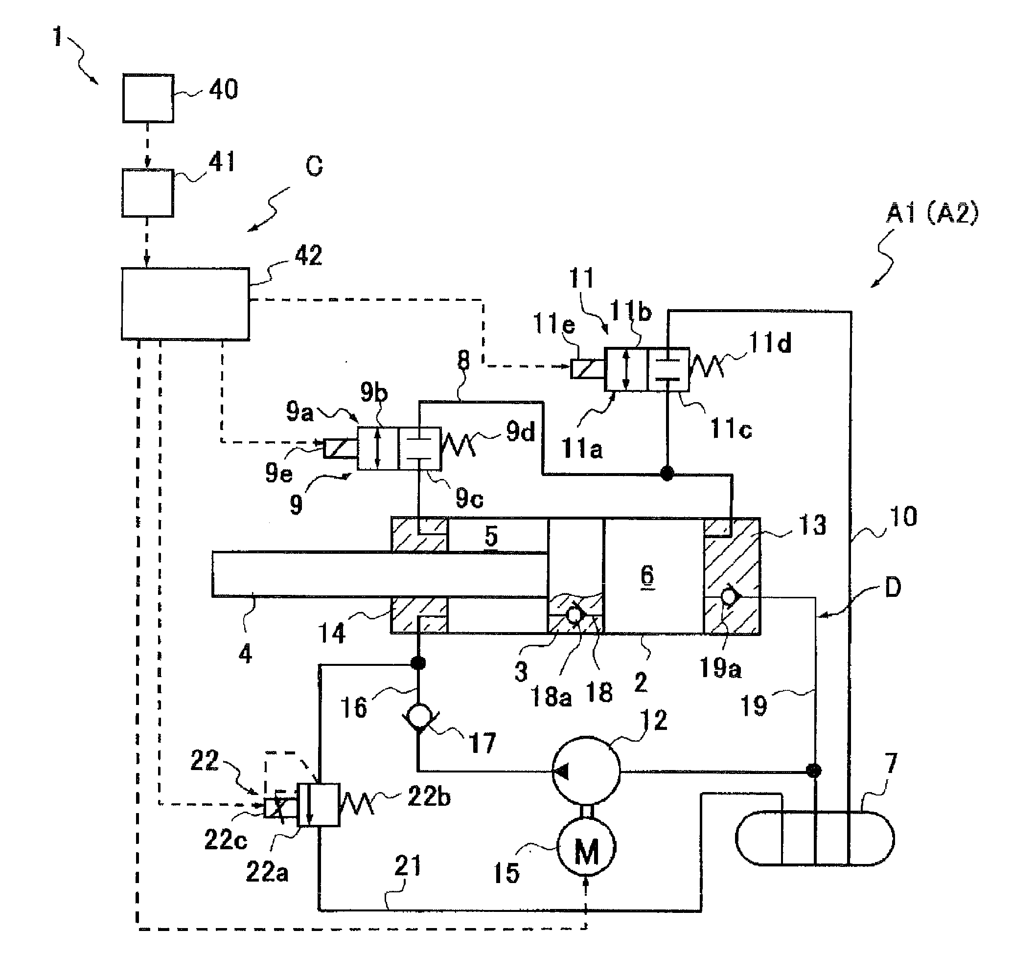
작동기(A1)는, 도 2에 도시한 바와 같이, 철도 차량의 대차(W) 및 차체(B)의 한쪽에 연결되는 실린더(2)와, 실린더(2) 내에 미끄럼 이동 가능하게 삽입되는 피스톤(3)과, 실린더(2) 내에 삽입되어서 피스톤(3)과 대차(W) 및 차체(B)의 다른 쪽에 연결되는 로드(4)와, 실린더(2) 내에 피스톤(3)으로 구획된 로드측실(5) 및 피스톤측실(6)과, 탱크(7)와, 로드측실(5)과 피스톤측실(6)을 연통하는 제1 유로(8)의 도중에 설치한 제1 개폐 밸브(9)와, 피스톤측실(6)과 탱크(7)를 연통하는 제2 통로(10)의 도중에 설치한 제2 개폐 밸브(11)와, 로드측실(5)로 액체를 공급하는 펌프(12)와, 펌프(12)를 구동하는 모터(15)를 구비하는 편 로드형의 작동기이다.2, the actuator A1 includes a
로드측실(5) 및 피스톤측실(6)에는 액체로서의 작동유가 충전되고, 탱크(7)에는 작동유 외에 기체가 충전된다. 또한, 탱크(7) 내의 기체는 압축하여 가압 상태로 유지할 필요는 없다.The
제1 개폐 밸브(9)를 개방하여 제1 유로(8)를 연통 상태로 하고, 제2 개폐 밸브(11)를 폐쇄하여 제2 통로(10)를 폐색 상태로 한 다음, 펌프(12)를 구동함으로써, 작동기(A1)가 신장 구동된다. 또한, 제2 개폐 밸브(11)를 개방하여 제2 통로(10)를 연통 상태로 하고, 제1 개폐 밸브(9)를 폐쇄하여 제1 유로(8)를 폐색 상태로 한 다음, 펌프(12)를 구동함으로써, 작동기(A1)가 수축 구동된다.The first opening and closing valve 9 is opened to bring the first flow path 8 into communication and the second opening and
이하, 작동기(A1)의 각 부에 대하여 상세하게 설명한다.Hereinafter, each part of the actuator A1 will be described in detail.
실린더(2)는 통 형상이며, 도 2 중 우측단부는 덮개(13)에 의해 폐색되고, 도 2 중 좌측단부는 링 형상의 로드 가이드(14)가 부착된다. 로드 가이드(14) 내에는, 실린더(2) 내에 이동 가능하게 삽입되는 로드(4)가 미끄럼 이동 가능하게 삽입된다. 로드(4)는 일단부가 실린더(2) 밖으로 돌출되고, 타단부가 실린더(2) 내에 미끄럼 이동 가능하게 삽입되어 있는 피스톤(3)에 연결된다.The
로드(4)의 외주와 로드 가이드(14) 사이는 도시하지 않은 시일 부재에 의해 시일되고, 실린더(2) 내는 밀폐 상태로 유지된다. 실린더(2) 내에 설치되어 피스톤(3)에 의해 구획되는 로드측실(5) 및 피스톤측실(6)에는 작동유가 충전된다.The space between the outer periphery of the
또한, 로드(4)의 단면적은 피스톤(3) 단면적의 2분의 1이며, 피스톤(3)의 로드측실(5)측의 수압 면적이 피스톤측실(6)측의 수압 면적의 2분의 1이 되도록 설정된다. 또한, 신장 구동 시와 수축 구동 시에서 로드측실(5)의 압력이 동일하면, 신축의 양쪽에서 발생되는 추력도 동일해지도록 설정되어 있고, 작동기(A1)의 변위량에 따른 유량도 신축 양측에서 동일해진다.The cross sectional area of the
작동기(A1)를 신장 구동시키는 경우, 로드측실(5)과 피스톤측실(6)을 연통시키므로, 로드측실(5) 내의 압력과 피스톤측실(6) 내의 압력이 동등해진다. 이 경우, 작동기(A1)의 발생 추력은 피스톤(3)에 있어서의 로드측실(5)측과 피스톤측실(6)측과의 수압 면적차에 상기 압력을 곱한 값이 된다.Since the
작동기(A1)를 수축 구동시킬 경우, 로드측실(5)과 피스톤측실(6)과의 연통을 차단하고, 피스톤측실(6)을 탱크(7)에 연통시킨다. 이 경우, 작동기(A1)의 발생 추력은 로드측실(5) 내의 압력에 피스톤(3)에 있어서의 로드측실(5)측의 수압 면적을 곱한 값이 된다.The communication between the
즉, 작동기(A1)의 발생 추력은 신축의 양쪽에서 피스톤(3)의 단면적의 2분의 1에 로드측실(5)의 압력을 곱한 값이 된다. 따라서, 작동기(A1)의 추력을 제어할 경우, 신장 구동, 수축 구동 모두 로드측실(5)의 압력을 제어하면 된다. 피스톤(3)의 로드측실(5)측의 수압 면적은 피스톤측실(6)측의 수압 면적의 2분의 1로 설정되므로, 신축에서 동일한 추력을 발생할 경우에는 신장 시와 수축 시에서 로드측실(5)의 압력은 동일한 값으로 제어하면 된다. 따라서, 제어가 간소해지는데다가, 신축에서 변위량에 대한 유량이 동일해지므로 신축 시의 응답성이 동등해진다고 하는 이점이 있다.That is, the generation thrust of the actuator A1 becomes a value obtained by multiplying the pressure of the
또한, 피스톤(3)의 로드측실(5)측의 수압 면적을 피스톤측실(6)측의 수압 면적의 2분의 1 이외로 설정한 경우에도, 로드측실(5)의 압력을 제어함으로써 작동기(A1)의 신축 시의 추력 제어를 할 수 있는 점은 동일하다.Even when the hydraulic pressure area on the side of the
로드(4)의 도 2 중 좌측단부와 실린더(2)의 우측단부를 폐색하는 덮개(13)에는, 도시하지 않은 부착부가 구비되어 있고, 이 부착부에 의해 작동기(A1)는 철도 차량에 있어서의 대차(W)와 차체(B) 사이에 개재 장착된다.An unshown attachment portion is provided in the
로드측실(5)과 피스톤측실(6)은, 제1 유로(8)에 의해 연통되어 있고, 제1 유로(8)의 도중에는 제1 개폐 밸브(9)가 설치된다. 또한, 제1 유로(8)는 실린더(2) 밖에서 로드측실(5)과 피스톤측실(6)을 연통하고 있지만, 피스톤(3) 내에 설치해도 된다.The
제1 개폐 밸브(9)는 전자기 개폐 밸브이며, 제1 유로(8)를 개방하여 로드측실(5)과 피스톤측실(6)을 연통하는 연통 포지션(9b)과, 로드측실(5)과 피스톤측실(6)과의 연통을 차단하는 차단 포지션(9c)을 구비한 밸브(9a)와, 차단 포지션(9c)을 채용하도록 밸브(9a)를 가압하는 스프링(9d)과, 통전 시에 밸브(9a)를 스프링(9d)의 가압력에 대항하여 연통 포지션(9b)으로 전환하는 솔레노이드(9e)를 구비한다.The first on-off valve 9 is an electromagnetic on-off valve and has a
피스톤측실(6)과 탱크(7)는, 제2 통로(10)에 의해 연통된다. 제2 통로(10)의 도중에는, 제2 개폐 밸브(11)가 설치된다. 제2 개폐 밸브(11)는 전자기 개폐 밸브이며, 제2 통로(10)를 개방하여 피스톤측실(6)과 탱크(7)를 연통하는 연통 포지션(11b)과, 피스톤측실(6)과 탱크(7)와의 연통을 차단하는 차단 포지션(11c)을 구비한 밸브(11a)와, 차단 포지션(11c)을 채용하도록 밸브(11a)를 가압하는 스프링(11d)과, 통전 시에 밸브(11a)를 스프링(11d)의 가압력에 대항하여 연통 포지션(11b)으로 전환하는 솔레노이드(11e)를 구비한다.The
펌프(12)는 모터(15)에 의해 구동되어, 일방향으로만 작동유를 토출한다. 펌프(12)의 토출구는 공급 통로(16)에 의해 로드측실(5)에 연통되고, 흡입구는 탱크(7)에 연통된다. 펌프(12)는 모터(15)에 의해 구동되면, 탱크(7)로부터 작동유를 흡입하여 로드측실(5)로 작동유를 공급한다.The
펌프(12)는 일방향으로만 작동유를 토출할 뿐더러 회전 방향의 전환 동작이 불필요하므로, 회전 전환 시에 토출량이 변화되어 버리는 등의 문제는 없어, 저렴한 기어 펌프 등을 사용할 수 있다. 또한, 펌프(12)의 회전 방향이 항상 동일한 방향이므로, 펌프(12)를 구동하는 구동원인 모터(15)의 회전 방향도 항상 동일한 방향이며, 회전 전환에 대한 높은 응답성을 요하지 않고, 그만큼 저렴한 모터(15)를 사용할 수 있다. 또한, 공급 통로(16)의 도중에는 로드측실(5)로부터 펌프(12)로의 작동유의 역류를 저지하는 역지 밸브(17)가 설치된다.Since the
펌프(12)로부터 소정의 토출 유량이 로드측실(5)로 공급되고 있는 상태에서, 작동기(A1)를 신장 작동시킬 때는, 제1 개폐 밸브(9)를 개방시켜 제2 개폐 밸브(11)를 개폐시킴으로써 로드측실(5) 내의 압력을 조절한다. 또한, 작동기(A1)를 수축 작동시킬 때는, 제2 개폐 밸브(11)를 개방시키고 제1 개폐 밸브(9)를 개폐시킴으로써 로드측실(5) 내의 압력을 조절한다. 이에 의해, 제진력 명령 값대로의 추력을 발생시킬 수 있다.Closing valve 9 is opened to allow the second on-off
또한, 제1 개폐 밸브(9) 및 제2 개폐 밸브(11)는 개방 밸브압을 조절 가능한 개폐 기능을 구비한 가변 릴리프 밸브라도 된다. 이 경우에는, 제1 개폐 밸브(9) 또는 제2 개폐 밸브(11)를 신축 작동 시에 개폐 작동시키는 것이 아닌, 개방 밸브압을 조절함으로써 작동기(A1)의 추력을 조절할 수도 있다.The first on-off valve 9 and the second on-off
또한, 펌프(12)의 토출 유량을 조절함으로써, 제진력 명령 값대로의 추력을 발생시킬 수도 있다. 이 경우, 로드측실(5)의 압력을 검출하기 위한 압력 센서, 모터(15) 또는 펌프(12)의 회전축에 작용하는 토크를 검출하는 센서, 로드(4)에 작용하는 하중을 검출하는 로드 센서, 또는 로드(4)의 왜곡을 검출하는 왜곡 센서를 설치해 두면, 작동기(A1)가 출력하는 추력을 계측할 수 있다.In addition, by adjusting the discharge flow rate of the
상기와 같이 작동기(A1)의 추력 조절이 가능하지만, 더욱 간단하게 추력 조절이 가능하도록, 본 실시 형태의 철도 차량용 제진 장치(1)는 로드측실(5)과 탱크(7)를 접속하는 배출 통로(21)와, 이 배출 통로(21)의 도중에 설치한 개방 밸브압을 변경 가능한 가변 릴리프 밸브(22)를 구비한다.The damper for the
가변 릴리프 밸브(22)는 비례 전자기 릴리프 밸브이며, 배출 통로(21)의 도중에 설치한 밸브체(22a)와, 배출 통로(21)를 차단하도록 밸브체(22a)를 가압하는 스프링(22b)과, 통전 시에 스프링(22b)의 가압력에 대항하는 추력을 발생하는 비례 솔레노이드(22c)를 구비한다. 가변 릴리프 밸브(22)는 비례 솔레노이드(22c)에 흐르는 전류량을 조절함으로써 개방 밸브압이 조절된다.The
가변 릴리프 밸브(22)는 밸브체(22a)에 작용하는 압력이 릴리프압(개방 밸브압)을 초과하면 배출 통로(21)를 개방한다. 즉, 배출 통로(21)의 상류가 되는 로드측실(5)의 압력이 릴리프압(개방 밸브압)을 초과하면, 배출 통로(21)를 개방시키는 방향으로 밸브체(22a)를 미는 상기 압력에 기인하는 추력과 비례 솔레노이드(22c)에 의한 추력과의 합력이, 배출 통로(21)를 차단시키는 방향으로 밸브체(22a)를 가압하는 스프링(22b)의 가압력을 이겨낸다. 이에 의해, 밸브체(22a)가 후퇴하여 배출 통로(21)가 개방된다.The
또한, 가변 릴리프 밸브(22)는 비례 솔레노이드(22c)에 공급하는 전류가 클수록, 비례 솔레노이드(22c)가 발생하는 추력이 증대하도록 설정되어 있고, 비례 솔레노이드(22c)에 공급하는 전류를 최대로 하면 개방 밸브압이 최소가 되고, 반대로 비례 솔레노이드(22c)에 전혀 전류를 공급하지 않으면 개방 밸브압이 최대가 된다.The
따라서, 작동기(A1)를 신축 작동시킬 때, 로드측실(5) 내의 압력을 가변 릴리프 밸브(22)의 개방 밸브압으로 조절하면, 로드측실(5)의 압력은 가변 릴리프 밸브(22)의 개방 밸브압을 조절함으로써 용이하게 조절할 수 있다. 이렇게 배출 통로(21)와 가변 릴리프 밸브(22)를 설치함으로써, 작동기(A1)의 추력을 조절하기 위하여 필요한 센서류가 불필요해진다. 또한, 제1 개폐 밸브(9) 및 제2 개폐 밸브(11)를 고속으로 개폐시키거나, 제1 개폐 밸브(9) 및 제2 개폐 밸브(11)를 개폐 기능을 구비한 가변 릴리프 밸브로 하거나, 펌프(12)의 토출 유량의 조절을 위하여 고도로 모터(15)를 제어하거나 할 필요가 없다. 따라서, 철도 차량용 제진 장치(1)가 저렴해져, 하드웨어적으로도 소프트웨어적으로도 견고한 시스템을 구축할 수 있다.Therefore, when the actuator A1 is retracted and operated, the pressure in the
또한, 가변 릴리프 밸브(22)는 공급되는 전류량으로 개방 밸브압을 비례적으로 변화시킬 수 있는 비례 전자기 릴리프 밸브를 사용했으므로 개방 밸브압의 제어가 간단해지지만, 개방 밸브압을 조절할 수 있는 릴리프 밸브이면 비례 전자기 릴리프 밸브에 한정되는 것은 아니다.Since the
가변 릴리프 밸브(22)는 제1 개폐 밸브(9) 및 제2 개폐 밸브(11)의 개폐 상태에 상관없이, 작동기(A1)에 신축 방향의 과대한 입력이 있어, 로드측실(5)의 압력이 개방 밸브압을 초과하면, 배출 통로(21)를 개방하여 로드측실(5)을 탱크(7)에 연통하고, 로드측실(5) 내의 압력을 탱크(7)로 릴리프하므로, 작동기(A1)의 시스템 전체를 보호할 수 있다. 이와 같이, 배출 통로(21) 및 가변 릴리프 밸브(22)를 설치함으로써 시스템의 보호가 가능해진다.The
또한, 작동기(A1)는 댐퍼 회로(D)를 구비하고 있다. 댐퍼 회로(D)는 제1 개폐 밸브(9) 및 제2 개폐 밸브(11)가 폐쇄되어 있는 경우에, 작동기(A1)를 댐퍼로서 기능시킨다. 댐퍼 회로(D)는, 피스톤측실(6)로부터 로드측실(5)을 향하는 작동유의 흐름만을 허용하는 정류 통로(18)와, 탱크(7)로부터 피스톤측실(6)을 향하는 작동유의 흐름만을 허용하는 흡입 통로(19)를 구비하고 있다. 또한, 작동기(A1)가, 배출 통로(21)와 가변 릴리프 밸브(22)를 구비하고 있으므로, 가변 릴리프 밸브(22)가 감쇠 밸브로서 기능을 한다.In addition, the actuator A1 is provided with a damper circuit D. The damper circuit D makes the actuator A1 function as a damper when the first on-off valve 9 and the second on-off
정류 통로(18)는 피스톤측실(6)과 로드측실(5)을 연통하고 있으며, 도중에 역지 밸브(18a)가 설치된다. 정류 통로(18)는 피스톤측실(6)로부터 로드측실(5)을 향하는 작동유의 흐름만을 허용하는 일방 통행의 통로이다. 흡입 통로(19)는 탱크(7)와 피스톤측실(6)을 연통하고 있고, 도중에 역지 밸브(19a)가 설치된다. 흡입 통로(19)는 탱크(7)로부터 피스톤측실(6)을 향하는 작동유의 흐름만을 허용하는 일방 통행의 통로이다.The
또한, 제1 개폐 밸브(9)의 차단 포지션(9c)을 역지 밸브로 함으로써 정류 통로(18)의 기능을 제1 유로(8)에 집약할 수 있고, 제2 개폐 밸브(11)의 차단 포지션(11c)을 역지 밸브로 함으로써 흡입 통로(19)의 기능을 제2 통로(10)에 집약할 수 있다.The function of the rectifying
댐퍼 회로(D)는 작동기(A1)에 있어서의 제1 개폐 밸브(9)와 제2 개폐 밸브(11)가 모두 차단 포지션(9c, 11c)으로 전환되면, 정류 통로(18), 흡입 통로(19) 및 배출 통로(21)에 의해, 로드측실(5), 피스톤측실(6) 및 탱크(7)를 줄줄이 연통시킨다. 정류 통로(18), 흡입 통로(19) 및 배출 통로(21)는 일방 통행의 통로이므로, 작동기(A1)가 외력에 의해 신축되면, 반드시 실린더(2)로부터 작동유가 배출되고, 배출된 작동유는 배출 통로(21)를 거쳐 탱크(7)로 복귀된다. 실린더(2)에서 부족해진 작동유는 흡입 통로(19)를 거쳐 탱크(7)로부터 실린더(2) 내로 공급된다.When the first opening / closing valve 9 and the second opening / closing
이 작동유의 흐름에 대하여 가변 릴리프 밸브(22)가 저항이 되어 실린더(2) 내의 압력을 개방 밸브압으로 조절하는 압력 제어 밸브로서 기능을 하므로, 작동기(A1)는 수동적인 유니플로우형의 댐퍼로서 기능을 한다. 또한, 가변 릴리프 밸브(22)와 배출 통로(21)를 형성하지 않고, 별도로 로드측실(5)과 탱크(7)를 접속하는 통로와, 이 통로의 도중에 배치되는 감쇠 밸브를 설치하여 댐퍼 회로(D)를 구성해도 된다.Since the
또한, 작동기(A1)의 각 기기에 대한 통전이 불가능해지는 장애 시에는, 제1 개폐 밸브(9) 및 제2 개폐 밸브(11)의 밸브(9a, 11a)가 스프링(9d, 11d)에 눌려져, 각각 차단 포지션(9c, 11c)으로 전환되고, 가변 릴리프 밸브(22)는 개방 밸브압이 최대로 고정된 압력 제어 밸브로서 기능을 한다. 따라서, 작동기(A1)는 자동으로 패시브 댐퍼로서 기능을 한다.The
작동기(A1)에 원하는 신장 방향의 추력을 발휘시킬 경우, 컨트롤러(C)는 작동기(A1)의 제1 개폐 밸브(9)를 연통 포지션(9b)으로 하고 제2 개폐 밸브(11)를 차단 포지션(11c)으로 하여, 작동기(A1)의 신축 상황에 따라서 모터(15)를 소정의 회전 속도로 회전시켜 펌프(12)로부터 실린더(2) 내로 작동유를 공급한다. 이에 의해, 로드측실(5)과 피스톤측실(6)이 연통하여 양자에 펌프(12)로부터 작동유가 공급되고, 피스톤(3)이 도 2중 좌측 방향으로 압박되어 작동기(A1)는 신장 방향의 추력을 발휘한다.The controller C sets the first opening and closing valve 9 of the actuator A1 to the
로드측실(5) 내 및 피스톤측실(6) 내의 압력이 가변 릴리프 밸브(22)의 개방 밸브압을 상회하면, 가변 릴리프 밸브(22)가 개방되어 작동유가 배출 통로(21)를 거쳐 탱크(7)로 도피하므로, 로드측실(5) 내 및 피스톤측실(6) 내의 압력은, 가변 릴리프 밸브(22)에 부여하는 전류에 의해 결정되는 가변 릴리프 밸브(22)의 개방 밸브압으로 제어된다.When the pressure in the
따라서, 작동기(A1)는 피스톤(3)에 있어서의 피스톤측실(6)측과 로드측실(5)측과의 수압 면적차에 상기한 가변 릴리프 밸브(22)에 의해 제어되는 로드측실(5) 내 및 피스톤측실(6) 내의 압력을 곱한 값의 추력을 신장 방향으로 발휘한다.Therefore, the actuator A1 is configured so that the
이에 반해, 작동기(A1)에 원하는 수축 방향의 추력을 발휘시킬 경우, 컨트롤러(C)는 작동기(A1)의 제1 개폐 밸브(9)를 차단 포지션(9c)으로 하고 제2 개폐 밸브(11)를 연통 포지션(11b)으로 하여, 작동기(A1)의 신축 상황에 따라서 모터(15)를 소정의 회전 속도로 회전시켜 펌프(12)로부터 로드측실(5) 내로 작동유를 공급한다. 이에 의해, 피스톤측실(6)과 탱크(7)가 연통하는 동시에 로드측실(5)에 펌프(12)로부터 작동유가 공급되므로, 피스톤(3)이 도 2 중 우측 방향으로 압박되어 작동기(A1)는 수축 방향의 추력을 발휘한다.On the other hand, when the actuator A1 exerts a desired thrust in the shrinking direction, the controller C sets the first opening / closing valve 9 of the actuator A1 to the
마찬가지로, 가변 릴리프 밸브(22)의 전류를 조절함으로써, 작동기(A1)는 피스톤(3)에 있어서의 로드측실(5)측의 수압 면적과 가변 릴리프 밸브(22)에 제어되는 로드측실(5) 내의 압력을 곱한 값의 추력을 수축 방향으로 발휘한다.Similarly, by adjusting the current of the
본 실시 형태에서는, 배출 통로(21)와 가변 릴리프 밸브(22)를 구비하고 있으므로, 모터(15)를 소정의 회전 속도로 정속 회전시킴으로써 추력 조절을 행할 수 있으므로, 펌프(12)의 회전 속도를 변화시킬 필요가 없어, 펌프(12)의 회전 변동에 따른 소음의 발생을 방지할 수 있는 동시에, 작동기(A1)의 제어 응답성을 향상시킬 수 있다. 또한, 가변 릴리프 밸브(22)에 의한 압력 조절로, 모터(15)의 회전 속도의 변경을 가미하여 작동기(A1)의 발생 추력을 조절할 수도 있다.Since the throttle control can be performed by constantly rotating the
또한, 작동기(A1)는 작동기로서 기능을 할 뿐만 아니라, 모터(15)의 구동 상황에 상관없이, 제1 개폐 밸브(9) 및 제2 개폐 밸브(11)의 개폐만으로 댐퍼로서 기능시킬 수 있으므로, 번거롭고 또한 급준한 밸브의 전환 동작을 행할 필요가 없어, 시스템의 응답성 및 신뢰성을 향상시킬 수 있다.The actuator A1 not only functions as an actuator but also can function as a damper by opening and closing only the first opening / closing valve 9 and the second opening / closing
또한, 작동기(A1)는 편 로드형이므로, 양 로드형의 작동기에 비교하여 스트로크 길이를 확보하기 쉬워, 작동기의 전체 길이를 단축하여, 철도 차량에 대한 탑재성을 향상시킬 수 있다.Further, since the actuator A1 is of the one-rod type, it is easy to secure the stroke length as compared with the actuators of the two rod type, and the overall length of the actuator can be shortened to improve the mountability to the railway vehicle.
또한, 작동기(A1)에 있어서의 펌프(12)로부터의 작동유 공급 및 신축 작동에 의한 작동유의 흐름은, 로드측실(5), 피스톤측실(6)을 차례로 통과하여 최종적으로 탱크(7)로 환류하므로, 로드측실(5) 또는 피스톤측실(6) 내에 기체가 혼입되어도, 작동기(A1)의 신축 작동에 의해 자립적으로 탱크(7)로 배출되어, 추진력 발생의 응답성 악화를 저지할 수 있다.The flow of the hydraulic oil from the
따라서, 작동기(A1)의 제조에 있어서, 번거로운 오일 중에서의 조립이나 진공 환경 하에서의 조립을 강요당하는 일 없이, 작동유의 고도인 탈기도 불필요해지므로, 생산성이 향상되는 동시에 제조 비용을 저감할 수 있다.Therefore, in the production of the actuator A1, it is not necessary to assemble in a troublesome oil or assembly in a vacuum environment, and it is also unnecessary to perform high-level deaeration of the operating oil, so that the productivity can be improved and the manufacturing cost can be reduced.
또한, 로드측실(5) 또는 피스톤측실(6) 내에 기체가 혼입되어도, 기체는 작동기(A1)의 신축 작동에 의해 자립적으로 탱크(7)로 배출되므로, 성능 회복을 위한 유지 보수를 빈번히 행할 필요가 없어, 보수면에 있어서의 노동력과 비용 부담을 경감할 수 있다.Even if gas is mixed into the
컨트롤러(C)는, 도 1 내지 도 3에 도시한 바와 같이, 차체(B)의 차량 진행 방향에 대하여 수평인 가로 방향의 횡가속도 α를 검출하는 가속도 센서(40)와, 횡가속도 α에 포함되는 곡선 주행 시의 정상 가속도, 드리프트 성분 및 노이즈를 제거하는 대역 통과 필터(41)와, 대역 통과 필터(41)로 여과한 횡가속도 α를 처리하여, 각 작동기(A1, A2)의 모터(15), 제1 개폐 밸브(9)의 솔레노이드(9e), 제2 개폐 밸브(11)의 솔레노이드(11e), 가변 릴리프 밸브(22)의 비례 솔레노이드(22c)로 제어 명령을 출력하는 제어부(42)를 구비한다.1 to 3, the controller C includes an
통상 제어 모드에서는, 이하에 설명한 바와 같이, 각 작동기(A1, A2)의 추력을 제어한다. 또한, 대역 통과 필터(41)로 횡가속도 α에 포함되는 곡선 주행 시의 정상 가속도가 제거되므로, 승차감을 악화시키는 진동만을 억제할 수 있다.In the normal control mode, thrusts of the actuators A1 and A2 are controlled as described below. In addition, since the normal acceleration at the time of running the curve included in the lateral acceleration? Is removed by the band-
제어부(42)는 가속도 센서(40)로 검지한 횡가속도 α를 적분하여 차체(B)의 가로 방향 속도를 구한다. 가로 방향 속도는, 예를 들어 도 1 중 좌측 방향의 속도를 플러스인 값으로서, 반대인 도 1 중 우측 방향의 속도를 마이너스인 값으로서 구한다. 또한, 차체(B)의 가로 방향 속도를 구하는데 다른 센서 등을 사용해도 된다.The
제어부(42)는, 또한 스카이훅 제어 규칙에 따라 가로 방향 속도에 스카이훅 게인을 곱하여 작동기(A1, A2)가 발생해야 할 추력의 크기 및 방향을 포함하여 이루어지는 제진력 명령 값을 구한다.The
제어부(42)는, 또한 제진력 명령 값을 구한 후, 제진력 명령 값대로 각 작동기(A1, A2)에 추력을 발휘시키기 위해, 이들 작동기(A1, A2)로 제어 명령을 부여한다. 구체적으로는, 제어부(42)는 제진력 명령 값으로부터 각 작동기(A1, A2)의 모터(15), 제1 개폐 밸브(9)의 솔레노이드(9e), 제2 개폐 밸브(11)의 솔레노이드(11e), 가변 릴리프 밸브(22)의 비례 솔레노이드(22c)로 부여해야 할 제어 명령을 구하여 해당 제어 명령을 출력한다. 또한, 제진력 명령 값으로부터 제어 명령을 구할 때, 현재 작동기(A1, A2)가 출력하고 있는 추력을 피드백하여 제어 명령을 구해도 된다.The
이상, 통상 제어 모드에서는, 컨트롤러(C)는 소정의 샘플링 타임 주기로 횡가속도를 샘플링하고, 상기한 처리를 실행하여, 제진력 명령 값을 구하여 각 작동기(A1, A2)의 추력을 제어하는 처리를 계속 행한다.As described above, in the normal control mode, the controller C samples the lateral acceleration at a predetermined sampling time period, executes the above-described processing, obtains the deceleration command value, and controls the thrust of each of the actuators A1 and A2 Continue to do it.
여기서, 철도 차량용 제진 장치(1)는 정지 상태로부터 전원이 투입되고 기동되어 통상 제어 모드로 이행하기 전에, 소정 시간 동안, 작동기(A1, A2)를 온기 운전한다.Here, the vibration isolation device for a
이 경우, 2개의 작동기(A1, A2) 중, 한쪽 작동기(A1)(A2)를 온기 운전할 때에는, 다른 작동기(A2)(A1)를 댐퍼로서 기능시킨다.In this case, when one of the actuators A1 and A2 is operated to warm up one of the actuators A1 and A2, the other actuators A2 and A1 function as a damper.
온기 운전은, 각 작동기(A1, A2) 모두, 제1 개폐 밸브(9), 제2 개폐 밸브(11)를 개방 밸브시킨 후, 모터(15)로 펌프(12)를 구동하고, 가변 릴리프 밸브(22)의 개방 밸브압을 최소로 한다.The warm-up operation is performed by driving the
이에 의해, 펌프(12)로부터 토출된 작동유는, 배출 통로(21)를 거쳐 탱크(7)로 복귀된다. 제1 개폐 밸브(9) 및 제2 개폐 밸브(11)의 양쪽이 개방되어 있으므로 로드측실(5)과 피스톤측실(6)이 탱크(7)로 통하고 있고, 로드측실(5) 및 피스톤측실(6)의 압력은 탱크압으로 유지되므로, 작동기(A1, A2)는 신장측으로도 수축측으로도 추력을 발휘하지 않는다. 따라서, 온기 운전에 따라 차체(B)가 작동기(A1, A2)에 의해 가진되는 일은 없다.Thus, the operating oil discharged from the
또한, 온기 운전에 필요로 하는 시간은 미리 결정되어, 예를 들어 철도 차량이 사용되는 지역에 있어서의 계절마다 평균 기온에 의해 결정된다. 이 경우, 동계 쪽이 하계보다 온기 운전하는 시간을 길게 하게 된다.Further, the time required for the warm-up operation is determined in advance and is determined by the average temperature every season in the area where the railway vehicle is used, for example. In this case, the winter time is longer than the summer time.
온기 운전은 소정 시간의 경과 후에 종료되고, 철도 차량용 제진 장치(1)는 통상 제어 모드로 이행한다. 온기 운전을 행함으로써, 작동기(A1, A2) 내의 작동유의 온도가 상승하므로, 통상 제어 모드로 이행 후에 작동기(A1, A2)에 목표대로의 추력을 발생시킬 수 있다.The warm-up operation is terminated after a lapse of a predetermined time, and the railway vehicle
또한, 작동유의 온도가, 작동기(A1, A2)가 설정대로의 추력을 발휘할 수 있는 온도가 되었을 때, 온기 운전을 종료하여 통상 제어 모드로 이행하도록 해도 된다. 이 경우, 작동유의 온도를 감시해 두고, 작동유의 온도가 온기 운전을 종료해도 되는 온도가 되었을 때, 온기 운전을 종료한다. 작동유의 온도는, 예를 들어 탱크(7) 내의 작동유의 온도를 검출하는 온도 센서에 의해 검출하여, 제어부(42)로 온도를 감시하면 된다.Further, when the temperature of the operating oil reaches a temperature at which the actuators A1 and A2 can exert the thrust as set, the warm-up operation may be terminated and the mode may be shifted to the normal control mode. In this case, the temperature of the operating oil is monitored, and when the temperature of the operating oil reaches a temperature at which the heating operation can be terminated, the warming operation is terminated. The temperature of the operating oil may be detected by, for example, a temperature sensor for detecting the temperature of the operating oil in the
또한, 제1 개폐 밸브(9)와 제2 개폐 밸브(11)가 개방되어 있어 로드측실(5)과 피스톤측실(6)이 탱크압으로 유지되므로, 가변 릴리프 밸브(22)의 개방 밸브압을 최소로 하지 않아도 작동기(A1, A2)가 추력을 발생하지 않는 상태로 유지할 수 있다. 그러나 관로 저항에 의해 약간 로드측실(5)과 피스톤측실(6) 사이에 차압이 발생하여 작동기(A1, A2)가 수축 방향의 추력을 발생할 가능성이 있다. 따라서, 실제로는 가변 릴리프 밸브(22)의 개방 밸브압을 최소로 함으로써 로드측실(5)의 상류측 압력을 작게 하여, 작동기(A1, A2)가 온기 운전 중에 추력을 발생해 버리는 것을 확실하게 저지하고 있다.Since the first and the second opening and
본 실시 형태의 철도 차량용 제진 장치(1)에 의하면, 기동 후로서 차체(B)의 진동을 억제하는 통상 제어 모드로 이행하기 전에 작동기(A1, A2)의 온기 운전을 실행하므로, 작동기(A1, A2) 내의 작동유의 온도가 너무 낮아 발생 추력이 불안정해져서 차체 진동을 효과적으로 억제할 수 없게 되는 등의 문제를 해소할 수 있다. 즉, 본 실시 형태에서는, 통상 제어 모드 이행 전에 작동기(A1, A2) 내의 작동유의 온도가 진동 억제에 적합한 온도가 되어, 작동기(A1, A2)의 발생 추력이 안정되어 차체 진동을 효과적으로 억제할 수 있다.Since the warming operation of the actuators A1 and A2 is carried out before the shift to the normal control mode in which the vibration of the vehicle body B is suppressed after the start of the operation, A2) is too low to generate an unstable thrust, so that it is not possible to effectively suppress the vibration of the vehicle body. That is, in the present embodiment, the temperature of the operating oil in the actuators A1 and A2 becomes a temperature suitable for vibration suppression before the transition to the normal control mode, and the generated thrust of the actuators A1 and A2 is stabilized, have.
또한, 온기 운전 중은 작동기(A1, A2)는, 추력을 발휘하지 않으므로, 온기 운전에 따라 차체(B)를 가진해 버려, 불필요하게 에너지를 소비해 버리는 일이 없다.In addition, during the warm-up operation, the actuators A1 and A2 do not exert thrust, so that the vehicle body B is caught by the warm-up operation, and unnecessary energy is not consumed.
또한, 본 실시 형태에서는 2개의 작동기(A1, A2)를 구비하여, 한쪽의 작동기(A1)를 온기 운전할 때에는, 다른 쪽의 작동기(A2)를 댐퍼로서 기능시키고, 다른 쪽의 작동기(A2)를 온기 운전할 때에는, 한쪽의 작동기(A1)를 댐퍼로서 기능시킨다.In this embodiment, two actuators A1 and A2 are provided so that when one actuator A1 is warmed up, the other actuator A2 functions as a damper and the other actuator A2 functions as a damper In warm-up operation, one of the actuators A1 functions as a damper.
댐퍼로서 기능시키는 작동기에서는, 제1 개폐 밸브(9) 및 제2 개폐 밸브(11)를 폐쇄하고, 펌프(12)를 정지시킨다. 가변 릴리프 밸브(22)는 통전하지 않거나 또는 작동기(A2)를 댐퍼로서 기능시키는 경우에 요구되는 감쇠력을 발생 가능한 개방 밸브압이 되도록 전류를 조절한다.In the actuator functioning as a damper, the first on-off valve 9 and the second on-off
그렇게 하면, 온기 운전 중에 어떠한 외력이 차체(B)나 대차(W)에 작용해도 차체(B)의 진동은 댐퍼로서 기능을 하는 작동기에 의해 억제되므로, 차체(B)가 전혀 자유롭게 좌우로 이동해 버리는 것을 방지할 수 있어, 안전하게 온기 운전하는 것이 가능하다.In this way, even when any external force acts on the vehicle body B or the truck W during warm-up operation, the vibration of the vehicle body B is suppressed by the actuator functioning as a damper, It is possible to safely operate the warmer.
또한, 본 실시 형태에서는, 2개의 작동기(A1, A2)를 구비하고 있지만, 3개 이상의 작동기를 구비해도 된다. 이 경우, 적어도 하나의 작동기를 댐퍼로서 기능시킨 다음 다른 작동기를 온기 운전시키면, 차체(B)가 완전히 자유롭게 좌우로 이동하는 것을 방지할 수 있어, 안전하게 온기 운전하는 것이 가능하다. 예를 들어, 3개의 작동기 중, 우선 2개의 작동기를 온기 운전시켜 나머지 하나를 댐퍼로서 기능시킨다. 계속하여 온기 운전이 끝나지 않은 작동기를 온기 운전시켜서, 온기 운전이 끝난 2개의 작동기 중 1개 이상을 댐퍼로서 기능시키면 된다.In the present embodiment, although two actuators A1 and A2 are provided, three or more actuators may be provided. In this case, if at least one actuator functions as a damper and the other actuator is operated in a warm mode, it is possible to prevent the vehicle body B from completely moving freely to the left and right, thereby enabling safe warm-up operation. For example, among three actuators, first, two actuators are operated in the warm-up mode, and the other is operated as a damper. Then, one or more of the two actuators that have been subjected to warm-up operation can be made to function as a damper by continuing the warm-up operation of the actuator whose warm-up operation has not been completed.
모든 작동기(A1, A2)에 대하여 온기 운전이 종료되면, 컨트롤러(C)는 통상 제어 모드로 이행하지만, 통상 제어 모드로 이행하기 전에, 철도 차량용 제진 장치(1)에 이상이 없는지 여부를 판정하는 자기 진단을 실행해도 된다.When the warming operation is completed for all the actuators A1 and A2, the controller C shifts to the normal control mode, but before shifting to the normal control mode, it is determined whether there is any abnormality in the railway vehicle
자기 진단은, 예를 들어 제1 개폐 밸브(9)와 제2 개폐 밸브(11)를 개방하여 펌프(12)를 구동하여, 가변 릴리프 밸브(22)의 개방 밸브압을 변화시킨 경우에, 작동기(A1, A2)가 신축하는지 여부를 감시하여, 신축할 경우에 이상이라 판단한다. 또한, 작동기(A1, A2)의 추력을 감시할 수 있는 경우, 온기 운전 후에 작동기(A1, A2)의 추력이 제어 명령대로 발생되는지 여부를 체크한다.In the self-diagnosis, for example, when the opening / closing valve 9 and the second opening / closing
또한, 온기 운전 후에 작동기(A1, A2)의 추력이 제어 명령대로 발생되는지 여부를 체크할 경우, 작동유의 온도에 의한 오차가 작아지므로, 이상을 검지하기 쉬워진다고 하는 이점이 있다. 즉, 온기 운전을 행하지 않고 추력 체크를 행할 경우, 작동유의 온도가 낮고 점도가 높아, 작동기(A1, A2)의 추력이 제어 명령보다도 지나치게 높아지므로 이것을 이상이라 검지할 수 없다. 이에 반해, 사전에 온기 운전을 행함으로써, 작동유 온도에 의해 추력이 과잉이 되는 것을 억제할 수 있으므로, 이상을 판단하기 위한 임계값을 작게 할 수 있어, 이상을 정확하게 발견할 수 있다.Further, when checking whether or not the thrust of the actuators A1 and A2 is generated according to the control command after the warm-up operation, the error due to the temperature of the operating oil becomes small, which makes it easy to detect an abnormality. That is, when the thrust check is performed without performing the warm operation, the temperature of the operating oil is low and the viscosity is high, so that the thrust of the actuators A1 and A2 becomes excessively higher than the control command. On the other hand, by performing the warm-up operation in advance, it is possible to suppress excessive thrust due to the operating oil temperature, so that the threshold value for judging the abnormality can be reduced and the abnormality can be accurately found.
컨트롤러(C)는, 하드웨어 자원으로서는 도시는 하지 않았지만, 예를 들어 가속도 센서(40)가 출력하는 신호를 도입하기 위한 A/D 변환기와, 대역 통과 필터(41)와, 대역 통과 필터(41)로 여과한 횡가속도 α를 도입하여 작동기(A1, A2)를 제어 및 자기 진단하는데 필요한 처리에 사용되는 프로그램이 저장되는 ROM(Read Only Memory) 등의 기억 장치와, 상기 프로그램을 기초로 한 처리를 실행하는 CPU(Central Processing Unit) 등의 연산 장치와, 상기 CPU에 기억 영역을 제공하는 RAM(Random Access Memory) 등의 기억 장치를 구비한다.The controller C includes, for example, an A / D converter for introducing a signal output from the
컨트롤러(C)의 제어부(42)는 CPU가 상기 각 처리를 행하기 위한 프로그램을 실행함으로써 실현된다. 또한, 적분기를 사용하여 횡가속도 α로부터 가로 방향 속도를 구해도 되고, 횡가속도 α를 대역 통과 필터(41) 및 적분기로 처리한 후에 위상 보상용의 필터로 처리해도 되고, 또한 대역 통과 필터(41), 적분기 및 위상 보상용의 필터 특성을 합성한 필터로 처리해도 된다. 위상 보상용의 필터는, 대역 통과 필터(41) 및 적분기로 처리한 후에 CPU가 프로그램을 실행함으로써 실현되어도 된다.The
또한, 컨트롤러(C)는 스카이훅 제어 규칙에 따라서 작동기(A1, A2)의 제진력 명령 값을 구하고 있지만, 다른 제어 규칙을 이용해도 된다.Further, although the controller C obtains the defibrillating force command value of the actuators A1 and A2 in accordance with the sky hook control rule, other control rules may be used.
이상, 본 발명의 실시 형태에 대하여 설명했지만, 상기 실시 형태는 본 발명의 적용예의 일부를 나타낸 것에 지나지 않으며, 본 발명의 기술적 범위를 상기 실시 형태의 구체적 구성에 한정할 취지는 아니다.Although the embodiments of the present invention have been described above, the above embodiments are only illustrative of some of the application examples of the present invention, and the technical scope of the present invention is not limited to the specific configurations of the above embodiments.
본 출원은 2011년 5월 30일에 일본 특허청에 출원된 일본 특허 출원 제2011-120599호를 기초로 하는 우선권을 주장하고, 이 출원의 모든 내용은 참조에 의해 본 명세서에 포함된다.This application is based upon and claims the benefit of priority from Japanese Patent Application No. 2011-120599 filed on May 30, 2011, the entire contents of which are incorporated herein by reference.
Claims (4)
상기 차체의 진동을 억제하는 철도 차량용 제진 장치이며,
기동 후로서 상기 차체의 진동을 억제하는 통상 제어 모드로 이행하기 전에, 상기 제1 개폐 밸브 및 상기 제2 개폐 밸브를 개방하여, 상기 펌프를 구동하여 상기 작동기를 온기 운전하며,
상기 작동기를 2개 이상 구비하고,
상기 작동기는 상기 제1 개폐 밸브 및 상기 제2 개폐 밸브가 폐쇄된 상태에서 상기 작동기를 댐퍼로서 기능시키는 댐퍼 회로를 구비하고,
상기 온기 운전 중, 적어도 하나의 상기 작동기를 댐퍼로서 기능시키는, 철도 차량용 제진 장치.A piston connected to one side of a vehicle body and a railway vehicle, a piston slidably inserted in the cylinder, a rod inserted in the cylinder and connected to the other side of the piston, the bogie and the vehicle body, A first open / close valve provided in the middle of a rod side chamber and a piston side chamber divided by the piston, a tank, and a first flow path communicating the rod side chamber and the piston side chamber, and a second opening / closing valve provided between the piston side chamber and the tank A second opening / closing valve installed in the middle of the passage, and an actuator having a pump for supplying liquid to the rod chamber,
A vibration damping device for a railway vehicle, which suppresses vibration of the vehicle body,
The first on-off valve and the second on-off valve are opened before the transition to the normal control mode in which the vibration of the vehicle body is suppressed after startup, the pump is driven to warm-
Wherein at least two actuators are provided,
Wherein the actuator includes a damper circuit for causing the actuator to function as a damper when the first opening / closing valve and the second opening / closing valve are closed,
And at least one of the actuators functions as a damper during the warm-up operation.
상기 온기 운전 중, 상기 가변 릴리프 밸브의 개방 밸브압이 최소로 설정되는, 철도 차량용 제진 장치.2. The apparatus according to claim 1, wherein the actuator has a discharge passage connecting the rod chamber to the tank, and a variable relief valve installed in the middle of the discharge passage to change the opening valve pressure,
And the opening valve pressure of the variable relief valve is set to the minimum during the warming-up operation.
Applications Claiming Priority (3)
| Application Number | Priority Date | Filing Date | Title |
|---|---|---|---|
| JPJP-P-2011-120599 | 2011-05-30 | ||
| JP2011120599A JP5822335B2 (en) | 2011-05-30 | 2011-05-30 | Vibration control device for railway vehicles |
| PCT/JP2012/063915 WO2012165471A1 (en) | 2011-05-30 | 2012-05-30 | Railway car vibration control device |
Publications (2)
| Publication Number | Publication Date |
|---|---|
| KR20130087544A KR20130087544A (en) | 2013-08-06 |
| KR101555107B1 true KR101555107B1 (en) | 2015-09-22 |
Family
ID=47259323
Family Applications (1)
| Application Number | Title | Priority Date | Filing Date |
|---|---|---|---|
| KR1020137014119A Expired - Fee Related KR101555107B1 (en) | 2011-05-30 | 2012-05-30 | Railway car vibration control device |
Country Status (7)
| Country | Link |
|---|---|
| US (1) | US8997950B2 (en) |
| EP (1) | EP2716517A4 (en) |
| JP (1) | JP5822335B2 (en) |
| KR (1) | KR101555107B1 (en) |
| CN (1) | CN103347767B (en) |
| RU (1) | RU2568533C2 (en) |
| WO (1) | WO2012165471A1 (en) |
Families Citing this family (21)
| Publication number | Priority date | Publication date | Assignee | Title |
|---|---|---|---|---|
| JPWO2013015358A1 (en) * | 2011-07-28 | 2015-02-23 | 日立オートモティブシステムズ株式会社 | Railcar dampers |
| JP5831830B2 (en) * | 2011-08-11 | 2015-12-09 | Kyb株式会社 | Vibration control device for railway vehicles |
| JP5731453B2 (en) * | 2012-08-24 | 2015-06-10 | カヤバ工業株式会社 | damper |
| JP5608252B2 (en) * | 2013-02-26 | 2014-10-15 | カヤバ工業株式会社 | Actuator |
| JP6134238B2 (en) * | 2013-09-11 | 2017-05-24 | Kyb株式会社 | Shock absorber |
| JP6336822B2 (en) * | 2014-05-23 | 2018-06-06 | Kyb株式会社 | Cylinder device |
| JP6368204B2 (en) * | 2014-09-19 | 2018-08-01 | Kyb株式会社 | Railway vibration control device |
| DE112016002019B4 (en) * | 2015-05-29 | 2021-07-29 | Hitachi Astemo, Ltd. | Vibration damper arrangement |
| JP6588756B2 (en) * | 2015-07-15 | 2019-10-09 | Kyb株式会社 | Actuator control device and actuator unit |
| JP6654943B2 (en) * | 2016-03-24 | 2020-02-26 | Kyb株式会社 | Railcar damper |
| US20180010302A1 (en) * | 2016-07-05 | 2018-01-11 | Harsco Technologies LLC | Apparatus and method for tamping ballast |
| JP6725356B2 (en) * | 2016-07-29 | 2020-07-15 | Kyb株式会社 | Damping device for railway vehicles |
| JP6231630B1 (en) * | 2016-08-12 | 2017-11-15 | Kyb株式会社 | Vibration control device for railway vehicles |
| JP6890058B2 (en) * | 2017-07-24 | 2021-06-18 | Ckd株式会社 | Cylinder control device and piston actuator device |
| JP6936754B2 (en) * | 2018-03-07 | 2021-09-22 | Kyb株式会社 | Vibration damping device for railway vehicles |
| JP2019157908A (en) * | 2018-03-08 | 2019-09-19 | Kyb株式会社 | Electric hydraulic pressure actuator for aircraft |
| CN110316210B (en) * | 2018-03-28 | 2023-10-20 | Kyb株式会社 | Vibration damping devices for railway vehicles |
| JP6951372B2 (en) * | 2019-01-23 | 2021-10-20 | Kyb株式会社 | Vibration damping device for railway vehicles |
| CN110155101B (en) * | 2019-05-17 | 2020-11-06 | 中车青岛四方机车车辆股份有限公司 | Transverse full-active control vibration reduction system and control method of controller thereof |
| US12410825B2 (en) | 2021-03-23 | 2025-09-09 | Cnh Industrial America Llc | System to reduce line loss in pressure control hydraulic circuit |
| JP7141553B1 (en) * | 2021-06-08 | 2022-09-22 | Kyb株式会社 | Cylinder device |
Citations (1)
| Publication number | Priority date | Publication date | Assignee | Title |
|---|---|---|---|---|
| JP2010065797A (en) | 2008-09-12 | 2010-03-25 | Kayaba Ind Co Ltd | Cylinder device |
Family Cites Families (10)
| Publication number | Priority date | Publication date | Assignee | Title |
|---|---|---|---|---|
| JPS55135210A (en) * | 1979-04-05 | 1980-10-21 | Hitachi Constr Mach Co Ltd | Hydraulic cylinder device |
| US4972762A (en) | 1989-03-06 | 1990-11-27 | Kubik Philip A | Warm-up circuit for hydraulic pilot control system |
| JP2575440Y2 (en) * | 1991-07-12 | 1998-06-25 | カヤバ工業株式会社 | Hydraulic equipment |
| CN1094855C (en) * | 1999-03-19 | 2002-11-27 | 萱场工业株式会社 | Shock absorber using using for transverse runout vibration absorption of stock and damping method |
| US6962050B2 (en) * | 2000-05-19 | 2005-11-08 | Komatsu Ltd. | Hybrid machine with hydraulic drive device |
| JP3775245B2 (en) * | 2001-06-11 | 2006-05-17 | コベルコ建機株式会社 | Pump controller for construction machinery |
| JP2003118571A (en) * | 2001-10-15 | 2003-04-23 | Nippon Sharyo Seizo Kaisha Ltd | Vibration suppressing device for rolling stock |
| JP2003139108A (en) * | 2001-11-07 | 2003-05-14 | Shimadzu Corp | Hydraulic actuator |
| JP5051363B2 (en) * | 2007-07-31 | 2012-10-17 | 日立オートモティブシステムズ株式会社 | Railway vehicle vibration control system |
| JP5462110B2 (en) * | 2009-09-22 | 2014-04-02 | 日本車輌製造株式会社 | Dampers for vibration control of railway vehicles |
-
2011
- 2011-05-30 JP JP2011120599A patent/JP5822335B2/en active Active
-
2012
- 2012-05-30 US US13/991,849 patent/US8997950B2/en not_active Expired - Fee Related
- 2012-05-30 RU RU2013124430/11A patent/RU2568533C2/en not_active IP Right Cessation
- 2012-05-30 KR KR1020137014119A patent/KR101555107B1/en not_active Expired - Fee Related
- 2012-05-30 CN CN201280007464.4A patent/CN103347767B/en active Active
- 2012-05-30 WO PCT/JP2012/063915 patent/WO2012165471A1/en not_active Ceased
- 2012-05-30 EP EP12792214.4A patent/EP2716517A4/en not_active Withdrawn
Patent Citations (1)
| Publication number | Priority date | Publication date | Assignee | Title |
|---|---|---|---|---|
| JP2010065797A (en) | 2008-09-12 | 2010-03-25 | Kayaba Ind Co Ltd | Cylinder device |
Also Published As
| Publication number | Publication date |
|---|---|
| US8997950B2 (en) | 2015-04-07 |
| EP2716517A4 (en) | 2015-03-11 |
| CN103347767B (en) | 2016-04-27 |
| JP2012245926A (en) | 2012-12-13 |
| WO2012165471A1 (en) | 2012-12-06 |
| KR20130087544A (en) | 2013-08-06 |
| JP5822335B2 (en) | 2015-11-24 |
| EP2716517A1 (en) | 2014-04-09 |
| CN103347767A (en) | 2013-10-09 |
| RU2013124430A (en) | 2014-12-10 |
| US20130248306A1 (en) | 2013-09-26 |
| RU2568533C2 (en) | 2015-11-20 |
Similar Documents
| Publication | Publication Date | Title |
|---|---|---|
| KR101555107B1 (en) | Railway car vibration control device | |
| TWI475161B (en) | Hydraulic cylinder device | |
| JP5564541B2 (en) | Actuator | |
| KR101529420B1 (en) | Railcar damping device | |
| WO2013137296A1 (en) | Vibration-suppression device for railway vehicle | |
| JP6018675B2 (en) | Vibration control device for railway vehicles | |
| JP5608252B2 (en) | Actuator | |
| US20150369263A1 (en) | Actuator unit | |
| KR101484439B1 (en) | Railcar damping device | |
| JP4884827B2 (en) | Vibration suppression device | |
| WO2019171911A1 (en) | Railroad car vibration damping device | |
| JP6231630B1 (en) | Vibration control device for railway vehicles | |
| JP6936754B2 (en) | Vibration damping device for railway vehicles | |
| KR101481267B1 (en) | Failsafe apparatus and control method for vehicle | |
| CN121111917A (en) | Cylinder device | |
| JP2002013502A (en) | Control valve for hydraulic system | |
| JP2020117055A (en) | Railway vehicle vibration suppressing device |
Legal Events
| Date | Code | Title | Description |
|---|---|---|---|
| A201 | Request for examination | ||
| PA0105 | International application |
St.27 status event code: A-0-1-A10-A15-nap-PA0105 |
|
| PA0201 | Request for examination |
St.27 status event code: A-1-2-D10-D11-exm-PA0201 |
|
| PG1501 | Laying open of application |
St.27 status event code: A-1-1-Q10-Q12-nap-PG1501 |
|
| E902 | Notification of reason for refusal | ||
| PE0902 | Notice of grounds for rejection |
St.27 status event code: A-1-2-D10-D21-exm-PE0902 |
|
| E902 | Notification of reason for refusal | ||
| PE0902 | Notice of grounds for rejection |
St.27 status event code: A-1-2-D10-D21-exm-PE0902 |
|
| E601 | Decision to refuse application | ||
| PE0601 | Decision on rejection of patent |
St.27 status event code: N-2-6-B10-B15-exm-PE0601 |
|
| AMND | Amendment | ||
| E13-X000 | Pre-grant limitation requested |
St.27 status event code: A-2-3-E10-E13-lim-X000 |
|
| P11-X000 | Amendment of application requested |
St.27 status event code: A-2-2-P10-P11-nap-X000 |
|
| P13-X000 | Application amended |
St.27 status event code: A-2-2-P10-P13-nap-X000 |
|
| PX0901 | Re-examination |
St.27 status event code: A-2-3-E10-E12-rex-PX0901 |
|
| PE0801 | Dismissal of amendment |
St.27 status event code: A-2-2-P10-P12-nap-PE0801 |
|
| PX0701 | Decision of registration after re-examination |
St.27 status event code: A-3-4-F10-F13-rex-PX0701 |
|
| X701 | Decision to grant (after re-examination) | ||
| GRNT | Written decision to grant | ||
| PR0701 | Registration of establishment |
St.27 status event code: A-2-4-F10-F11-exm-PR0701 |
|
| PR1002 | Payment of registration fee |
St.27 status event code: A-2-2-U10-U12-oth-PR1002 Fee payment year number: 1 |
|
| PG1601 | Publication of registration |
St.27 status event code: A-4-4-Q10-Q13-nap-PG1601 |
|
| R18-X000 | Changes to party contact information recorded |
St.27 status event code: A-5-5-R10-R18-oth-X000 |
|
| PR1001 | Payment of annual fee |
St.27 status event code: A-4-4-U10-U11-oth-PR1001 Fee payment year number: 4 |
|
| PC1903 | Unpaid annual fee |
St.27 status event code: A-4-4-U10-U13-oth-PC1903 Not in force date: 20190917 Payment event data comment text: Termination Category : DEFAULT_OF_REGISTRATION_FEE |
|
| PC1903 | Unpaid annual fee |
St.27 status event code: N-4-6-H10-H13-oth-PC1903 Ip right cessation event data comment text: Termination Category : DEFAULT_OF_REGISTRATION_FEE Not in force date: 20190917 |
|
| R18-X000 | Changes to party contact information recorded |
St.27 status event code: A-5-5-R10-R18-oth-X000 |