KR101552420B1 - Scanning signal line driving circuit, display device provided therewith, and scanning signal line driving method - Google Patents
Scanning signal line driving circuit, display device provided therewith, and scanning signal line driving method Download PDFInfo
- Publication number
- KR101552420B1 KR101552420B1 KR1020137033460A KR20137033460A KR101552420B1 KR 101552420 B1 KR101552420 B1 KR 101552420B1 KR 1020137033460 A KR1020137033460 A KR 1020137033460A KR 20137033460 A KR20137033460 A KR 20137033460A KR 101552420 B1 KR101552420 B1 KR 101552420B1
- Authority
- KR
- South Korea
- Prior art keywords
- node
- potential
- level
- signal
- circuit
- Prior art date
- Legal status (The legal status is an assumption and is not a legal conclusion. Google has not performed a legal analysis and makes no representation as to the accuracy of the status listed.)
- Expired - Fee Related
Links
Images


Classifications
-
- G—PHYSICS
- G09—EDUCATION; CRYPTOGRAPHY; DISPLAY; ADVERTISING; SEALS
- G09G—ARRANGEMENTS OR CIRCUITS FOR CONTROL OF INDICATING DEVICES USING STATIC MEANS TO PRESENT VARIABLE INFORMATION
- G09G3/00—Control arrangements or circuits, of interest only in connection with visual indicators other than cathode-ray tubes
- G09G3/20—Control arrangements or circuits, of interest only in connection with visual indicators other than cathode-ray tubes for presentation of an assembly of a number of characters, e.g. a page, by composing the assembly by combination of individual elements arranged in a matrix no fixed position being assigned to or needed to be assigned to the individual characters or partial characters
- G09G3/34—Control arrangements or circuits, of interest only in connection with visual indicators other than cathode-ray tubes for presentation of an assembly of a number of characters, e.g. a page, by composing the assembly by combination of individual elements arranged in a matrix no fixed position being assigned to or needed to be assigned to the individual characters or partial characters by control of light from an independent source
- G09G3/36—Control arrangements or circuits, of interest only in connection with visual indicators other than cathode-ray tubes for presentation of an assembly of a number of characters, e.g. a page, by composing the assembly by combination of individual elements arranged in a matrix no fixed position being assigned to or needed to be assigned to the individual characters or partial characters by control of light from an independent source using liquid crystals
-
- H—ELECTRICITY
- H03—ELECTRONIC CIRCUITRY
- H03K—PULSE TECHNIQUE
- H03K3/00—Circuits for generating electric pulses; Monostable, bistable or multistable circuits
- H03K3/01—Details
- H03K3/012—Modifications of generator to improve response time or to decrease power consumption
-
- G—PHYSICS
- G09—EDUCATION; CRYPTOGRAPHY; DISPLAY; ADVERTISING; SEALS
- G09G—ARRANGEMENTS OR CIRCUITS FOR CONTROL OF INDICATING DEVICES USING STATIC MEANS TO PRESENT VARIABLE INFORMATION
- G09G3/00—Control arrangements or circuits, of interest only in connection with visual indicators other than cathode-ray tubes
- G09G3/20—Control arrangements or circuits, of interest only in connection with visual indicators other than cathode-ray tubes for presentation of an assembly of a number of characters, e.g. a page, by composing the assembly by combination of individual elements arranged in a matrix no fixed position being assigned to or needed to be assigned to the individual characters or partial characters
- G09G3/34—Control arrangements or circuits, of interest only in connection with visual indicators other than cathode-ray tubes for presentation of an assembly of a number of characters, e.g. a page, by composing the assembly by combination of individual elements arranged in a matrix no fixed position being assigned to or needed to be assigned to the individual characters or partial characters by control of light from an independent source
- G09G3/36—Control arrangements or circuits, of interest only in connection with visual indicators other than cathode-ray tubes for presentation of an assembly of a number of characters, e.g. a page, by composing the assembly by combination of individual elements arranged in a matrix no fixed position being assigned to or needed to be assigned to the individual characters or partial characters by control of light from an independent source using liquid crystals
- G09G3/3611—Control of matrices with row and column drivers
- G09G3/3674—Details of drivers for scan electrodes
- G09G3/3677—Details of drivers for scan electrodes suitable for active matrices only
-
- G—PHYSICS
- G02—OPTICS
- G02F—OPTICAL DEVICES OR ARRANGEMENTS FOR THE CONTROL OF LIGHT BY MODIFICATION OF THE OPTICAL PROPERTIES OF THE MEDIA OF THE ELEMENTS INVOLVED THEREIN; NON-LINEAR OPTICS; FREQUENCY-CHANGING OF LIGHT; OPTICAL LOGIC ELEMENTS; OPTICAL ANALOGUE/DIGITAL CONVERTERS
- G02F1/00—Devices or arrangements for the control of the intensity, colour, phase, polarisation or direction of light arriving from an independent light source, e.g. switching, gating or modulating; Non-linear optics
- G02F1/01—Devices or arrangements for the control of the intensity, colour, phase, polarisation or direction of light arriving from an independent light source, e.g. switching, gating or modulating; Non-linear optics for the control of the intensity, phase, polarisation or colour
- G02F1/13—Devices or arrangements for the control of the intensity, colour, phase, polarisation or direction of light arriving from an independent light source, e.g. switching, gating or modulating; Non-linear optics for the control of the intensity, phase, polarisation or colour based on liquid crystals, e.g. single liquid crystal display cells
- G02F1/133—Constructional arrangements; Operation of liquid crystal cells; Circuit arrangements
-
- G—PHYSICS
- G09—EDUCATION; CRYPTOGRAPHY; DISPLAY; ADVERTISING; SEALS
- G09G—ARRANGEMENTS OR CIRCUITS FOR CONTROL OF INDICATING DEVICES USING STATIC MEANS TO PRESENT VARIABLE INFORMATION
- G09G3/00—Control arrangements or circuits, of interest only in connection with visual indicators other than cathode-ray tubes
- G09G3/20—Control arrangements or circuits, of interest only in connection with visual indicators other than cathode-ray tubes for presentation of an assembly of a number of characters, e.g. a page, by composing the assembly by combination of individual elements arranged in a matrix no fixed position being assigned to or needed to be assigned to the individual characters or partial characters
- G09G3/34—Control arrangements or circuits, of interest only in connection with visual indicators other than cathode-ray tubes for presentation of an assembly of a number of characters, e.g. a page, by composing the assembly by combination of individual elements arranged in a matrix no fixed position being assigned to or needed to be assigned to the individual characters or partial characters by control of light from an independent source
- G09G3/36—Control arrangements or circuits, of interest only in connection with visual indicators other than cathode-ray tubes for presentation of an assembly of a number of characters, e.g. a page, by composing the assembly by combination of individual elements arranged in a matrix no fixed position being assigned to or needed to be assigned to the individual characters or partial characters by control of light from an independent source using liquid crystals
- G09G3/3611—Control of matrices with row and column drivers
- G09G3/3696—Generation of voltages supplied to electrode drivers
-
- G—PHYSICS
- G11—INFORMATION STORAGE
- G11C—STATIC STORES
- G11C19/00—Digital stores in which the information is moved stepwise, e.g. shift registers
- G11C19/28—Digital stores in which the information is moved stepwise, e.g. shift registers using semiconductor elements
-
- G—PHYSICS
- G09—EDUCATION; CRYPTOGRAPHY; DISPLAY; ADVERTISING; SEALS
- G09G—ARRANGEMENTS OR CIRCUITS FOR CONTROL OF INDICATING DEVICES USING STATIC MEANS TO PRESENT VARIABLE INFORMATION
- G09G2310/00—Command of the display device
- G09G2310/02—Addressing, scanning or driving the display screen or processing steps related thereto
- G09G2310/0264—Details of driving circuits
- G09G2310/0286—Details of a shift registers arranged for use in a driving circuit
Landscapes
- Engineering & Computer Science (AREA)
- Physics & Mathematics (AREA)
- General Physics & Mathematics (AREA)
- Theoretical Computer Science (AREA)
- Crystallography & Structural Chemistry (AREA)
- Chemical & Material Sciences (AREA)
- Computer Hardware Design (AREA)
- Nonlinear Science (AREA)
- Optics & Photonics (AREA)
- Mathematical Physics (AREA)
- Control Of Indicators Other Than Cathode Ray Tubes (AREA)
- Liquid Crystal Display Device Control (AREA)
- Liquid Crystal (AREA)
Abstract
소비 전력을 저감시키면서 스위칭 소자의 신뢰성을 높이는 것을 목적으로 한다. 수직 귀선 기간이 되면, 엔드 신호(ED)가 로우 레벨에서 하이 레벨로 변화한다. 주사 신호선 구동 회로의 시프트 레지스터에 포함되는, 서로 종속 접속된 m단의 쌍안정 회로의 1 내지 m-1단째 제1 노드(N1)의 전위가 확실하게 로우 레벨로 유지됨과 함께, 1 내지 m-1단째 제2 노드(N2)의 전위가 하이 레벨에서 로우 레벨로 변화한다. m단째의 쌍안정 회로에서는, m단째 제1 노드(N1)의 전위가 하이 레벨에서 로우 레벨로 변화함과 함께, m단째 제2 노드(N2)의 전위가 로우 레벨로 유지된다. 또한, 클록 신호(CKA, CKB)의 쌍안정 회로에의 공급이 정지된다. 다음 수직 주사 기간에서의 기입 기간까지, 각 단에서의 제1 노드(N1)의 전위 및 제2 노드(N2)의 전위가 로우 레벨로 유지된다.And aims to improve reliability of a switching element while reducing power consumption. When the vertical retrace period is reached, the end signal ED changes from a low level to a high level. The potentials of the first node (N1) of the first to (m-1) th stages of the m stages of the bistable circuits connected to each other in the shift register of the scanning signal line driving circuit are reliably maintained at the low level, The potential of the first node N2 changes from the high level to the low level. In the m-th stage of the bistable circuit, the potential of the m-th first node N1 changes from the high level to the low level, and the potential of the m-th second node N2 is maintained at the low level. Also, supply of the clock signals (CKA, CKB) to the bistable circuit is stopped. The potential of the first node N1 and the potential of the second node N2 in each stage are maintained at the low level until the writing period in the next vertical scanning period.

Description
본 발명은 주사 신호선 구동 회로, 그것을 구비한 표시 장치 및 주사 신호선의 구동 방법에 관한 것으로, 특히, 모놀리식화에 적합한 주사 신호선 구동 회로, 그것을 구비한 표시 장치 및 그 주사 신호선 구동 회로에 의한 주사 신호선의 구동 방법에 관한 것이다.The present invention relates to a scanning signal line driving circuit, a display device having the same, and a driving method of the scanning signal line. More particularly, the present invention relates to a scanning signal line driving circuit suitable for monolithicization, And a method of driving the same.
종래, 액정 표시 장치의 게이트 라인(주사 신호선)을 구동하기 위한 게이트 드라이버(주사 신호선 구동 회로)는 액정 패널을 구성하는 기판의 주변부에 IC(Integrated Circuit) 칩으로서 탑재되는 경우가 많았다. 그러나 최근 들어, 기판 상에 직접 게이트 드라이버를 형성하는 일이 점점 많이 이루어지고 있다. 이러한 게이트 드라이버는 「모놀리식 게이트 드라이버」등으로 불리고 있다.Conventionally, a gate driver (scanning signal line driving circuit) for driving gate lines (scanning signal lines) of a liquid crystal display device is often mounted as an IC (Integrated Circuit) chip in a peripheral portion of a substrate constituting a liquid crystal panel. However, in recent years, it has become more and more common to form a gate driver directly on a substrate. Such a gate driver is called a " monolithic gate driver ".
모놀리식 게이트 드라이버를 구비한 액정 표시 장치에서는, 종래부터 아몰퍼스 실리콘(a-Si)을 사용한 박막 트랜지스터(이하 「a-SiTFT」라고 함)가 구동 소자로서 채용되었다. 그러나 최근 들어, 미결정 실리콘(μc-Si)을 사용한 박막 트랜지스터(이하 「μc-SiTFT」라고 함) 또는 산화물 반도체(예를 들어 IGZO)를 사용한 박막 트랜지스터가 구동 소자로서 채용되기 시작하고 있다. 이하에서는, IGZO를 사용한 박막 트랜지스터를 「IGZOTFT」라고 한다. 이것들의 μc-SiTFT 및 IGZOTFT는 a-SiTFT보다도 이동도가 높다. 이로 인해, μc-SiTFT 또는 IGZOTFT를 구동 소자로서 채용함으로써, 액정 표시 장치의 프레임 면적의 축소 및 고정밀화를 실현할 수 있다.In a liquid crystal display device provided with a monolithic gate driver, a thin film transistor (hereinafter referred to as "a-Si TFT") using amorphous silicon (a-Si) has been employed as a driving element. However, in recent years, thin film transistors using microcrystalline silicon (μc-Si) (hereinafter referred to as μc-SiTFT) or oxide semiconductors (eg, IGZO) have started to be employed as driving elements. Hereinafter, the thin film transistor using IGZO is referred to as " IGZOTFT ". These μc-SiTFT and IGZOTFT have higher mobility than the a-SiTFT. Therefore, by adopting the μc-Si TFT or the IGZOTFT as the driving device, the frame area of the liquid crystal display device can be reduced and high-precision can be realized.
그런데, 액티브 매트릭스형의 액정 표시 장치의 표시부에는, 복수개의 소스 라인(영상 신호선)과, 복수개의 게이트 라인과, 이들의 복수개의 소스 라인과 복수개의 게이트 라인의 교차점에 각각 대응하여 설치된 복수개의 화소 형성부가 포함되어 있다. 이들의 화소 형성부는, 매트릭스 형상으로 배치됨으로써 화소 어레이를 구성하고 있다. 각 화소 형성부는, 대응하는 교차점을 통과하는 게이트 라인에 게이트 단자가 접속됨과 함께, 당해 교차점을 통과하는 소스 라인에 소스 단자가 접속된 박막 트랜지스터(스위칭 소자) 및 화소 전압값을 유지하기 위한 화소 용량 등을 포함하고 있다. 액티브 매트릭스형의 액정 표시 장치에는, 또한, 상술한 게이트 드라이버와, 소스 라인을 구동하기 위한 소스 드라이버(영상 신호선 구동 회로)가 설치되어 있다.Incidentally, in the display portion of the active matrix type liquid crystal display device, a plurality of source lines (video signal lines), a plurality of gate lines, and a plurality of pixels Forming portion. These pixel forming portions are arranged in a matrix to constitute a pixel array. Each pixel forming portion includes a thin film transistor (switching element) having a gate terminal connected to a gate line passing through a corresponding intersection point, a source terminal connected to a source line passing through the intersection point, and a pixel capacitor And the like. The active matrix type liquid crystal display device is further provided with the above-described gate driver and a source driver (video signal line driver circuit) for driving the source line.
화소 전압값을 나타내는 영상 신호는 소스 라인에 의해 전달되지만, 각 소스 라인은 복수행분의 화소 전압값을 나타내는 영상 신호를 일시(동시)에 전달할 수 없다. 이로 인해, 매트릭스 형상으로 배치된 상술한 화소 형성부 내의 화소 용량에의 영상 신호의 기입(충전)은 1행씩 순차적으로 행해진다. 따라서, 복수개의 게이트 라인이 소정 기간씩 순차적으로 선택되도록, 게이트 드라이버는 복수단을 포함하여 이루어지는 시프트 레지스터에 의해 구성되어 있다. 시프트 레지스터의 각 단은, 각 시점에서 2개의 상태(제1 상태 및 제2 상태) 중 어느 한쪽의 상태로 되어 있어서 당해 상태를 나타내는 신호(이하, 「상태 신호」라고 함)를 주사 신호로서 출력하는 쌍안정 회로로 되어 있다. 그리고, 시프트 레지스터 내의 복수의 쌍안정 회로부터 순차적으로 액티브한 주사 신호가 출력됨으로써, 상술한 바와 같이, 화소 용량에의 영상 신호의 기입이 1행씩 순차적으로 행해진다.The video signal representing the pixel voltage value is transmitted by the source line but each source line can not transmit the video signal representing the pixel voltage value of the multiple times at the same time. As a result, the writing (charging) of the video signal into the pixel capacitance in the above-described pixel forming portion arranged in a matrix is sequentially performed one row at a time. Therefore, the gate driver is composed of a shift register including a plurality of stages so that a plurality of gate lines are sequentially selected for predetermined periods. Each stage of the shift register is in one of two states (first state and second state) at each time point, and outputs a signal indicating the state (hereinafter referred to as a " state signal ") as a scanning signal And is a bistable circuit. By successively outputting active scanning signals from the plurality of bistable circuits in the shift register, the writing of the video signal into the pixel capacitance is performed sequentially one row at a time, as described above.
종래의 게이트 드라이버에 있어서의 쌍안정 회로는, 예를 들어 도 32에 도시한 바와 같이 구성되어 있다. 이러한 쌍안정 회로는, 예를 들어 특허문헌 1에 개시되어 있다. 또한, 도 32에서의 트랜지스터(M3 및 M7)는, 특허문헌 1에 개시되어 있는 바와 같이 멀티 게이트화된 구성이어도 된다. 이하에서는, 도 32에 도시하는 쌍안정 회로를 「제1 종래예」라고 한다. 이 제1 종래예에서는, 전단으로부터 보내지는 주사 신호(GOUT)(i-1)(세트 신호(S))가 하이 레벨이 되면, 트랜지스터(M3)가 온 상태가 되므로, 제2 노드(N2)의 전위는 로우 레벨이 된다. 이에 의해, 트랜지스터(M5 및 M6)가 오프 상태가 된다. 따라서, 주사 신호(GOUT)(i-1)가 하이 레벨이 됨으로써, 제1 노드(N1)의 전위가 하이 레벨이 되고, 콘덴서(C1)가 충전된다. 이 상태일 때, 클록 신호(CK)의 전위가 게이트 라인에 나타난다. 이상에 의해, 각 쌍안정 회로에 있어서 전단으로부터 보내지는 주사 신호(GOUT)(i-1)가 하이 레벨이 된 후, 당해 각 쌍안정 회로에 제공하는 클록 신호(CK)의 전위를 하이 레벨로 함으로써, 시프트 레지스터 내의 복수의 쌍안정 회로부터 순차적으로 액티브한 주사 신호가 출력된다. 이에 의해, 복수개의 게이트 라인이 1개씩 순차적으로 구동된다. 각 쌍안정 회로에 있어서, 액티브한 주사 신호를 출력하기 위한 동작이 행해지는 기간 이외의 기간(후술하는 「통상 동작 기간」)에는, 제1 노드(N1)의 전위가 로우 레벨에서 유지되도록 제2 노드(N2)의 전위는 하이 레벨에서 유지되어 있다.The conventional bistable circuit in the gate driver is configured as shown in Fig. 32, for example. Such a bistable circuit is disclosed in, for example,
상술한 바와 같이, 상기 통상 동작 기간에, 제1 노드(N1)의 전위가 로우 레벨에서 유지되도록 제2 노드(N2)의 전위는 하이 레벨에서 유지될 필요가 있다. 이로 인해, 이 통상 동작 기간에서는, 상술한 트랜지스터(M5 및 M6)의 게이트 단자에는 하이 레벨의 전위(제2 노드(N2)의 전위)가 항상 제공된다. 액티브한 주사 신호를 출력하기 위한 동작이 행해지는 기간은 각 수직 주사 기간에서 얼마 안되므로, 트랜지스터(M5 및 M6)의 게이트 단자에는 실질적으로 직류의 전위가 제공된다. 그 결과, 이들의 트랜지스터(M5 및 M6)에 발생하는 임계값 변동이 커지므로, 트랜지스터의 신뢰성의 저하를 초래하게 된다.As described above, in the normal operation period, the potential of the second node N2 needs to be maintained at a high level so that the potential of the first node N1 is maintained at a low level. For this reason, in this normal operation period, a high level potential (potential of the second node N2) is always provided to the gate terminals of the above-described transistors M5 and M6. Since the period during which the operation for outputting the active scan signal is performed is small in each vertical scanning period, the gate terminals of the transistors M5 and M6 are provided with a substantially DC potential. As a result, variations in the threshold value occurring in these transistors M5 and M6 become large, which results in lowering the reliability of the transistor.
본원 발명에 관련하여 특허문헌 2에는, 도 33에 도시한 바와 같이, 입력부(920), 풀업 구동부(930), 풀 다운 구동부(940) 및 출력부(950)에 의해 구성되는 쌍안정 회로를 복수 포함한 게이트 드라이버가 개시되어 있다. 이하에서는, 도 33에 도시하는 쌍안정 회로를 「제2 종래예」라고 한다. 이 제2 종래예에 있어서의 입력부(920)는 트랜지스터(T1)를 포함하고, 풀업 구동부(930)는 트랜지스터(T9 및 T10)를 포함하고, 풀 다운 구동부(940)는 트랜지스터(T3, T4, T7, T8 및 T11)를 포함하고, 출력부(950)는 트랜지스터(T1, T5, T6) 및 콘덴서(C1)를 포함한다. 트랜지스터(T4 및 T5)의 게이트 단자에는 제2 노드가 접속되어 있다. 이들 트랜지스터(T4 및 T5)는 각각 상술한 트랜지스터(M5 및 M6)에 상당한다. 이 쌍안정 회로에는 2상의 클록 신호(CK1 및 CK2)(듀티비1/4)가 제공된다. 클록 신호(CK1)는, 트랜지스터(T1)의 드레인 단자와, 트랜지스터(T9)의 게이트 단자 및 드레인 단자와, 트랜지스터(T11)의 게이트 단자에 제공된다. 이 클록 신호(CK1)는 또한, 트랜지스터(T9)를 통하여 트랜지스터(T4)의 게이트 단자와 트랜지스터(T5)의 게이트 단자에도 제공된다. 클록 신호(CK2)는, 트랜지스터(T8)의 게이트 단자와, 트랜지스터(T10)의 게이트 단자 및 드레인 단자에 제공된다. 이 클록 신호(CK2)는 또한, 트랜지스터(T10)를 통하여 트랜지스터(T6)의 게이트 단자에도 제공된다.As shown in FIG. 33, in
이 제2 종래예에서는, 상기 제1 종래예와 마찬가지로, 액티브한 주사 신호를 출력하기 위한 동작이 행해지는 기간에서 제2 노드(N2)의 전위가 로우 레벨이 된다. 한편, 상기 통상 동작 기간에서는, 제2 노드(N2)의 전위는, 클록 신호(CK1)가 하이 레벨이 되면 하이 레벨이 되고, 클록 신호(CK2)가 하이 레벨이 되면 로우 레벨이 된다. 따라서, 이 제2 노드(N2)가 접속된 트랜지스터(T4 및 T5)의 게이트 단자에는 듀티비가 실질적으로 1/2의 전위가 제공되게 된다. 그 결과, 이들 트랜지스터(T4 및 T5)에 발생하는 임계값 변동을 억제할 수 있으므로, 트랜지스터의 신뢰성을 높일 수 있다.In this second conventional example, the potential of the second node N2 becomes a low level in a period in which an operation for outputting an active scanning signal is performed, similarly to the first conventional example. Meanwhile, in the normal operation period, the potential of the second node N2 becomes a high level when the clock signal CK1 becomes a high level and becomes a low level when a clock signal CK2 becomes a high level. Therefore, the gate terminals of the transistors T4 and T5 to which the second node N2 is connected are provided with a potential substantially 1/2 duty ratio. As a result, variations in the threshold value occurring in these transistors T4 and T5 can be suppressed, so that the reliability of the transistor can be enhanced.
그러나, 상기 제2 종래예에 따르면, 클록 신호가 제공되는 트랜지스터의 수가 많아지므로, 소비 전력이 증대한다.However, according to the second conventional example, since the number of transistors provided with a clock signal increases, power consumption increases.
따라서, 본 발명은 소비 전력을 저감시키면서 스위칭 소자의 신뢰성을 높인 주사 신호선 구동 회로, 그것을 구비한 표시 장치 및 주사 신호선의 구동 방법을 제공하는 것을 목적으로 한다.SUMMARY OF THE INVENTION It is therefore an object of the present invention to provide a scanning signal line driving circuit which increases the reliability of a switching element while reducing power consumption, a display device having the same, and a method of driving the scanning signal line.
본 발명의 제1 국면은, 복수의 주사 신호선을 구동하는 주사 신호선 구동 회로이며,A first aspect of the present invention is a scanning signal line driving circuit for driving a plurality of scanning signal lines,
서로 종속 접속된 복수의 쌍안정 회로를 포함하고, 외부로부터 입력되어 온 레벨과 오프 레벨을 주기적으로 반복하는 클록 신호에 기초하여 상기 복수의 쌍안정 회로의 출력 신호를 순차적으로 액티브로 하는 시프트 레지스터를 구비하고,A shift register including a plurality of bistable circuits cascade-connected to each other and sequentially activating output signals of the plurality of bistable circuits based on a clock signal periodically repeating a level input from the outside and an off level, Respectively,
각 쌍안정 회로는,Each bistable circuit comprises:
제1 노드에 접속되고, 수취한 신호에 기초하여 상기 제1 노드의 전위를 변화시키는 제1 구동부와,A first driver connected to the first node for changing the potential of the first node based on the received signal,
제2 노드에 접속되고, 수취한 신호에 기초하여 상기 제2 노드의 전위를 변화시키는 제2 구동부와,A second driver connected to the second node for changing the potential of the second node based on the received signal,
상기 제1 노드 및 상기 제2 노드에 접속되고, 상기 제1 노드의 전위 및 상기 제2 노드의 전위가 각각 온 레벨 및 오프 레벨이며, 또한, 상기 제1 구동부가 수취한 신호의 전위가 오프 레벨일 때, 액티브한 상기 출력 신호를 상기 클록 신호에 기초하여 출력하는 출력부를 갖고,The potential of the first node and the potential of the second node are on level and off level, respectively, and the potential of the signal received by the first driver is off level And outputting the active output signal on the basis of the clock signal,
상기 제1 구동부는, 상기 제2 노드가 제어 단자에 접속되고, 상기 제1 노드가 한쪽 도통 단자에 접속되고, 오프 레벨의 전위가 다른 쪽의 도통 단자에 제공된 제1 노드 턴오프용 스위칭 소자를 갖고,The first driver may include a first node turn-off switching element having the second node connected to the control terminal, the first node connected to one of the conduction terminals, and the off-level potential provided to the other conduction terminal Have,
상기 출력부는, 상기 제2 노드가 제어 단자에 접속되고, 상기 출력 신호를 출력하기 위한 출력 노드가 한쪽 도통 단자에 접속되고, 오프 레벨의 전위가 다른 쪽의 도통 단자에 제공된 출력 노드 턴오프용 스위칭 소자를 갖고,The output node is connected to the control terminal, the output node for outputting the output signal is connected to one of the conduction terminals, and the off-state potential is supplied to the other conduction terminal for the output node turn- Device,
상기 제1 구동부 및 상기 제2 구동부가, 각 수직 주사 기간 중 2수평 주사 기간 이상의 소정 기간에서 상기 제1 노드의 전위 및 상기 제2 노드의 전위를 각각 오프 레벨로 유지하는 것을 특징으로 한다.The first driving unit and the second driving unit maintain the potential of the first node and the potential of the second node at off levels in a predetermined period of two horizontal scanning periods or more in each vertical scanning period.
본 발명의 제2 국면은, 본 발명의 제1 국면에 있어서,According to a second aspect of the present invention, in the first aspect of the present invention,
상기 소정 기간에 있어서, 상기 복수의 쌍안정 회로에의 상기 클록 신호의 공급이 정지되는 것을 특징으로 한다.And the supply of the clock signal to the plurality of bistable circuits is stopped in the predetermined period.
본 발명의 제3 국면은, 본 발명의 제2 국면에 있어서,According to a third aspect of the present invention, in the second aspect of the present invention,
상기 소정 기간이 길수록 상기 클록 신호의 주파수가 높아지는 것을 특징으로 한다.And the frequency of the clock signal increases as the predetermined period is longer.
본 발명의 제4 국면은, 본 발명의 제2 국면에 있어서,According to a fourth aspect of the present invention, in the second aspect of the present invention,
상기 제1 구동부 및 상기 제2 구동부는, 전원 투입 후부터 최초의 수직 주사 기간의 개시까지의 동안에 또한, 상기 제1 노드의 전위 및 상기 제2 노드의 전위를 각각 오프 레벨로 유지하고,Wherein the first driver and the second driver respectively keep the potential of the first node and the potential of the second node off during the period from power-on to the start of the first vertical scanning period,
전원 투입 후부터 최초의 수직 주사 기간의 개시까지의 동안에 또한, 상기 복수의 쌍안정 회로에의 상기 클록 신호의 공급이 정지되는 것을 특징으로 한다.The supply of the clock signal to the plurality of bistable circuits is stopped while the power is turned on until the start of the first vertical scanning period.
본 발명의 제5 국면은, 본 발명의 제2 국면에 있어서,According to a fifth aspect of the present invention, in the second aspect of the present invention,
상기 시프트 레지스터에 있어서의 최종단의 쌍안정 회로의 출력 신호가 액티브 된 후에 상기 출력 신호를 비액티브로 하기 위하여 전위가 온 레벨이 되는 엔드 신호에 기초하여, 상기 소정 기간에 있어서, 상기 복수의 쌍안정 회로에의 상기 클록 신호의 공급을 정지시키는 클록 제어 회로를 또한 구비하는 것을 특징으로 한다.And an output circuit for outputting the output signal of the bistable circuit of the final stage in the shift register in accordance with an end signal whose potential is on level for deactivating the output signal after the output signal of the final- And a clock control circuit for stopping supply of the clock signal to the stabilization circuit.
본 발명의 제6 국면은, 본 발명의 제2 국면에 있어서,According to a sixth aspect of the present invention, in the second aspect of the present invention,
최종단의 쌍안정 회로에 있어서의 제1 구동부는, 상기 엔드 신호가 제어 단자에 제공되고, 상기 제1 노드가 한쪽 도통 단자에 접속되고, 오프 레벨의 전위가 다른 쪽의 도통 단자에 제공된 제1 엔드용 스위칭 소자를 또한 갖고,The first driver in the last-stage bistable circuit may be configured such that the end signal is provided to the control terminal, the first node is connected to one of the conduction terminals, and the off-level potential is supplied to the first conduction terminal End switching element,
각 쌍안정 회로에 있어서의 상기 제2 구동부는, 상기 엔드 신호가 제어 단자에 제공되고, 상기 제2 노드가 한쪽 도통 단자에 접속되고, 오프 레벨의 전위가 다른 쪽의 도통 단자에 제공된 제2 엔드용 스위칭 소자를 갖는 것을 특징으로 한다.Wherein the second driving unit in each bistable circuit is configured such that the end signal is provided to the control terminal, the second node is connected to one conducting terminal, and the off-level potential is supplied to the other conducting terminal And has a switching element for a power supply.
본 발명의 제7 국면은, 본 발명의 제6 국면에 있어서,According to a seventh aspect of the present invention, in the sixth aspect of the present invention,
최종단 이외의 각 단의 쌍안정 회로에 있어서의 제1 구동부는, 상기 제1 엔드용 스위칭 소자를 또한 갖는 것을 특징으로 한다.And the first driving section in the bistable circuit at each stage other than the final stage also has the switching element for the first end.
본 발명의 제8 국면은, 본 발명의 제6 국면에 있어서,According to an eighth aspect of the present invention, in the sixth aspect of the present invention,
최전단 이외의 각 단의 쌍안정 회로에 있어서의 제2 구동부는, 각 수직 주사 기간의 개시의 타이밍에서 온 레벨이 되는 스타트 신호에 기초하여 상기 제2 노드의 전위를 온 레벨을 향하여 변화시키는 스타트용 스위칭 소자를 또한 갖는 것을 특징으로 한다.And the second driving unit in each stage of the bistable circuit except for the frontmost stage changes the potential of the second node toward the ON level on the basis of the start signal that becomes the ON level at the start timing of each vertical scanning period And further has a switching element for the switching element.
본 발명의 제9 국면은, 본 발명의 제8 국면에 있어서,According to a ninth aspect of the present invention, in the eighth aspect of the present invention,
상기 제1 구동부는, 세트 신호에 기초하여 상기 제1 노드의 전위를 온 레벨을 향하여 변화시키는 제1 노드 턴온용 스위칭 소자를 또한 갖고,The first driver further has a first node turn-on switching element for changing the potential of the first node toward the on level based on the set signal,
최전단의 쌍안정 회로에 있어서의 상기 세트 신호는 상기 스타트 신호이며,The set signal in the bistable circuit at the foremost stage is the start signal,
최전단 이외의 쌍안정 회로에 있어서의 상기 세트 신호는 상기 쌍안정 회로의 전단의 쌍안정 회로의 출력 신호인 것을 특징으로 한다.And the set signal in the bistable circuit other than the foremost stage is an output signal of the bistable circuit in the preceding stage of the bistable circuit.
본 발명의 제10 국면은, 본 발명의 제9 국면에 있어서,According to a tenth aspect of the present invention, in the ninth aspect of the present invention,
상기 출력부는,The output unit includes:
상기 제1 노드가 도통 단자에 접속되고, 상기 클록 신호가 한쪽 도통 단자에 제공되고, 상기 출력 노드가 다른 쪽의 도통 단자에 접속된 출력 제어용 스위칭 소자와, An output control switching element in which the first node is connected to the conduction terminal, the clock signal is provided to one conduction terminal, and the output node is connected to the other conduction terminal,
상기 출력 제어용 스위칭 소자의 제어 단자가 일단부에 접속되고, 상기 출력 노드가 타단부에 접속된 용량 소자를 또한 갖는 것을 특징으로 한다.A control terminal of the switching element for output control is connected to one end, and the output node is also connected to the other end.
본 발명의 제11 국면은, 본 발명의 제10 국면에 있어서,An eleventh aspect of the present invention provides, in a tenth aspect of the present invention,
상기 제2 구동부는, 상기 제2 노드가 한쪽 도통 단자에 접속되고, 오프 레벨의 전위가 다른 쪽의 도통 단자에 제공된 제2 노드 턴오프용 스위칭 소자를 또한 갖는 것을 특징으로 한다.And the second driving section is characterized in that the second node is connected to one conduction terminal and the off-level potential is also provided for the other conduction terminal.
본 발명의 제12 국면은, 본 발명의 제11 국면에 있어서,According to a twelfth aspect of the present invention, in the eleventh aspect of the present invention,
상기 제2 구동부에는, 상기 제2 노드 턴오프용 스위칭 소자로서,Wherein the second driver includes a switching element for turning on the second node,
상기 세트 신호가 제어 단자에 제공되고, 상기 제2 노드가 한쪽 도통 단자에 접속되고, 오프 레벨의 전위가 다른 쪽의 도통 단자에 제공된 제1의 제2 노드 턴오프용 스위칭 소자와,A first second node turn-off switching element in which the set signal is provided to a control terminal, the second node is connected to one conduction terminal, and a potential of an off level is provided to the other conduction terminal,
상기 출력 노드가 제어 단자에 접속되고, 상기 제2 노드가 한쪽 도통 단자에 접속되고, 오프 레벨의 전위가 다른 쪽의 도통 단자에 제공된 제2의 제2 노드 턴오프용 스위칭 소자가 설치되어 있는 것을 특징으로 한다.A second second node turn-off switching element in which the output node is connected to the control terminal, the second node is connected to one conduction terminal, and the off-level potential is provided to the other conduction terminal .
본 발명의 제13 국면은, 본 발명의 제11 국면에 있어서,A thirteenth aspect of the present invention is the eleventh aspect of the present invention,
상기 제2 노드 턴오프용 스위칭 소자의 제어 단자가 상기 제1 노드에 접속되어 있는 것을 특징으로 한다.And a control terminal of the switching element for turning off the second node is connected to the first node.
본 발명의 제14 국면은, 본 발명의 제11 국면에 있어서,In a fourteenth aspect of the present invention, in the eleventh aspect of the present invention,
최전단 이외의 각 단의 쌍안정 회로에 있어서의 제2 구동부는, 상기 쌍안정 회로의 후단의 쌍안정 회로의 출력 신호에 기초하여 상기 제2 노드의 전위를 온 레벨을 향하여 변화시키는 제2 노드 턴온용 스위칭 소자를 또한 갖는 것을 특징으로 한다.And a second drive unit in each stage of the bistable circuit except the frontmost stage is configured to switch the potential of the second node toward the on level based on the output signal of the bistable circuit at the rear stage of the bistable circuit, And has a turn-on switching device.
본 발명의 제15 국면은, 본 발명의 제11 국면에 있어서,A fifteenth aspect of the present invention is the eleventh aspect of the present invention,
상기 클록 신호는, 서로 1수평 주사 기간만큼 위상이 어긋난 제1 클록 신호 및 제2 클록 신호를 포함하여 이루어지고,Wherein the clock signal includes a first clock signal and a second clock signal that are out of phase with each other by one horizontal scanning period,
상기 출력 제어용 스위칭 소자의 한쪽 도통 단자에는 상기 제1 클록 신호가 제공되고,The first clock signal is provided to one conduction terminal of the switching element for output control,
상기 제2 구동부는, 상기 제2 클록 신호에 기초하여 상기 제2 노드의 전위를 온 레벨을 향하여 변화시키는 전하 보충용 스위칭 소자를 또한 갖는 것을 특징으로 한다.And the second driving section further has a charge replenishing switching element for changing the potential of the second node toward the ON level based on the second clock signal.
본 발명의 제16 국면은, 표시 장치이며,A sixteenth aspect of the present invention is a display device,
복수의 주사 신호선이 배치된 표시부와,A display section in which a plurality of scanning signal lines are arranged,
상기 복수의 주사 신호선을 구동하는 주사 신호선 구동 회로와,A scanning signal line driving circuit for driving the plurality of scanning signal lines,
상기 주사 신호선 구동 회로에 온 레벨과 오프 레벨을 주기적으로 반복하는 클록 신호를 공급하는 표시 제어 회로를 구비하고,And a display control circuit for supplying a clock signal for periodically repeating the ON level and the OFF level to the scanning signal line driving circuit,
상기 주사 신호선 구동 회로는, 서로 종속 접속된 복수의 쌍안정 회로를 갖고, 상기 클록 신호에 기초하여 상기 복수의 쌍안정 회로의 출력 신호를 순차적으로 액티브로 하는 시프트 레지스터를 포함하고,Wherein the scanning signal line driving circuit includes a plurality of bistable circuits connected to each other in a cascade and includes a shift register for sequentially activating output signals of the plurality of bistable circuits based on the clock signal,
각 쌍안정 회로는,Each bistable circuit comprises:
제1 노드에 접속되고, 수취한 신호에 기초하여 상기 제1 노드의 전위를 변화시키는 제1 구동부와,A first driver connected to the first node for changing the potential of the first node based on the received signal,
제2 노드에 접속되고, 수취한 신호에 기초하여 상기 제2 노드의 전위를 변화시키는 제2 구동부와,A second driver connected to the second node for changing the potential of the second node based on the received signal,
상기 제1 노드 및 상기 제2 노드에 접속되고, 상기 제1 노드의 전위 및 상기 제2 노드 전위가 각각 온 레벨 및 오프 레벨이며, 또한, 상기 제1 구동부가 수취한 신호의 전위가 오프 레벨일 때, 액티브한 상기 출력 신호를 상기 클록 신호에 기초하여 출력하는 출력부를 갖고,And the potential of the first node and the potential of the second node are respectively on level and off level and the potential of the signal received by the first driver is off level And an output section for outputting the active output signal on the basis of the clock signal,
상기 제1 구동부는, 상기 제2 노드가 제어 단자에 접속되고, 상기 제1 노드가 한쪽 도통 단자에 접속되고, 오프 레벨의 전위가 다른 쪽의 도통 단자에 제공된 제1 노드 턴오프용 스위칭 소자를 갖고,The first driver may include a first node turn-off switching element having the second node connected to the control terminal, the first node connected to one of the conduction terminals, and the off-level potential provided to the other conduction terminal Have,
상기 출력부는, 상기 제2 노드가 제어 단자에 접속되고, 상기 출력 신호를 출력하기 위한 출력 노드가 한쪽 도통 단자에 접속되고, 오프 레벨의 전위가 다른 쪽의 도통 단자에 제공된 출력 노드 턴오프용 스위칭 소자를 갖고,The output node is connected to the control terminal, the output node for outputting the output signal is connected to one of the conduction terminals, and the off-state potential is supplied to the other conduction terminal for the output node turn- Device,
상기 제1 구동부 및 상기 제2 구동부가, 각 수직 주사 기간 중 2수평 주사 기간 이상의 소정 기간에서 상기 제1 노드의 전위 및 상기 제2 노드의 전위를 각각 오프 레벨로 유지하는 것을 특징으로 한다.The first driving unit and the second driving unit maintain the potential of the first node and the potential of the second node at off levels in a predetermined period of two horizontal scanning periods or more in each vertical scanning period.
본 발명의 제17 국면은, 본 발명의 제16 국면에 있어서,A seventeenth aspect of the present invention resides in the sixteenth aspect of the present invention,
상기 소정 기간에 있어서, 상기 복수의 쌍안정 회로에의 상기 클록 신호의 공급이 정지되는 것을 특징으로 한다.And the supply of the clock signal to the plurality of bistable circuits is stopped in the predetermined period.
본 발명의 제18 국면은, 본 발명의 제17 국면에 있어서,According to an eighteenth aspect of the present invention, in the seventeenth aspect of the present invention,
상기 주사 신호선 구동 회로는, 상기 시프트 레지스터에 있어서의 최종단의 쌍안정 회로의 출력 신호가 액티브가 된 후에 상기 출력 신호를 비액티브로 하기 위하여 전위가 온 레벨이 되는 엔드 신호에 기초하여, 상기 소정 기간에 있어서, 상기 복수의 쌍안정 회로에의 상기 클록 신호의 공급을 정지시키는 클록 제어 회로를 또한 포함하는 것을 특징으로 한다.Wherein the scanning signal line driving circuit controls the scanning signal line driving circuit such that the output signal of the bistable circuit at the final stage in the shift register becomes active after the output signal of the bistable circuit at the final stage becomes active, And a clock control circuit for stopping supply of the clock signal to the plurality of bistable circuits during a period of time.
본 발명의 제19 국면은, 본 발명의 제17 국면에 있어서,A nineteenth aspect of the present invention provides the seventeenth aspect of the present invention,
상기 표시 제어 회로는, 상기 소정 기간에 있어서, 상기 복수의 쌍안정 회로에의 상기 클록 신호의 공급을 정지하는 것을 특징으로 한다.The display control circuit stops supply of the clock signal to the plurality of bistable circuits in the predetermined period.
본 발명의 제20 국면은, 본 발명의 제17 국면에 있어서,A twentieth aspect of the present invention is the seventeenth aspect of the present invention,
상기 표시 제어 회로가, 상기 소정 기간이 길수록 상기 클록 신호의 주파수를 높이는 것을 특징으로 한다.And the display control circuit increases the frequency of the clock signal as the predetermined period is longer.
본 발명의 제21 국면은, 본 발명의 제16 국면부터 제20 국면까지 중 어느 하나에 있어서,A twenty-first aspect of the present invention provides any one of the sixteenth to twentieth aspects of the present invention,
상기 표시부와 상기 주사 신호선 구동 회로가 일체적으로 형성되어 있는 것을 특징으로 한다.And the display section and the scanning signal line drive circuit are integrally formed.
본 발명의 제22 국면은, 서로 종속 접속된 복수의 쌍안정 회로를 포함하고, 외부로부터 입력되어 온 레벨과 오프 레벨을 주기적으로 반복하는 클록 신호에 기초하여 상기 복수의 쌍안정 회로의 출력 신호를 순차적으로 액티브로 하는 시프트 레지스터를 구비한 주사 신호선 구동 회로에 의한 복수의 주사 신호선의 구동 방법이며,A twenty-second aspect of the present invention is a liquid crystal display device including a plurality of bistable circuits connected to each other in a cascade connection and outputting an output signal of the plurality of bistable circuits based on a clock signal periodically repeating a level inputted from the outside and an off- There is provided a method of driving a plurality of scanning signal lines by a scanning signal line driving circuit having a shift register which is sequentially made active,
각 쌍안정 회로에 있어서 신호를 수취하고, 상기 신호에 기초하여 상기 쌍안정 회로에 있어서의 제1 노드의 전위를 변화시키는 스텝과,A step of receiving a signal in each bistable circuit and changing a potential of the first node in the bistable circuit based on the signal;
각 쌍안정 회로에 있어서 신호를 수취하고, 상기 신호에 기초하여 상기 쌍안정 회로에 있어서의 제2 노드의 전위를 변화시키는 스텝과,Receiving a signal in each bistable circuit and changing a potential of a second node in the bistable circuit based on the signal;
상기 제1 노드의 전위 및 상기 제2 노드의 전위가 각각 온 레벨 및 오프 레벨이며, 또한, 상기 제1 노드의 전위를 변화시키는 스텝에 있어서 각 쌍안정 회로가 수취한 신호의 전위가 오프 레벨일 때, 액티브한 상기 출력 신호를 출력하는 스텝을 구비하고,The potential of the first node and the potential of the second node are on level and off level, respectively, and in the step of changing the potential of the first node, the potential of the signal received by each bistable circuit is off level And outputting the active output signal,
각 쌍안정 회로는,Each bistable circuit comprises:
상기 제2 노드가 제어 단자에 접속되고, 상기 제1 노드가 한쪽 도통 단자에 접속되고, 오프 레벨의 전위가 다른 쪽의 도통 단자에 제공된 제1 노드 턴오프용 스위칭 소자와,A first node turn-off switching element in which the second node is connected to a control terminal, the first node is connected to one of the conduction terminals, and the off-level potential is provided to the other conduction terminal,
상기 제2 노드가 제어 단자에 접속되고, 상기 출력 신호를 출력하기 위한 출력 노드가 한쪽 도통 단자에 접속되고, 오프 레벨의 전위가 다른 쪽의 도통 단자에 제공된 출력 노드 턴오프용 스위칭 소자를 갖고,An output node for outputting the output signal is connected to one of the conduction terminals and a potential of the off level is provided to the other conduction terminal for the output node turning-off switching element, the second node is connected to the control terminal,
상기 제1 노드의 전위를 변화시키는 스텝에서는, 각 수직 주사 기간 중 2수평 주사 기간 이상의 소정 기간에서 상기 제1 노드의 전위가 오프 레벨로 유지되고,In the step of changing the potential of the first node, the potential of the first node is maintained at an off level in a predetermined period of two horizontal scanning periods or more in each vertical scanning period,
상기 제2 노드의 전위를 변화시키는 스텝에서는, 상기 소정 기간에서 상기 제2 노드의 전위가 오프 레벨로 유지되는 것을 특징으로 한다.In the step of changing the potential of the second node, the potential of the second node is maintained at the off level in the predetermined period.
본 발명의 제23 국면은, 본 발명의 제22 국면에 있어서,A twenty-third aspect of the present invention is the twenty-second aspect of the present invention,
상기 소정 기간에 있어서, 상기 복수의 쌍안정 회로에의 상기 클록 신호의 공급을 정지하는 스텝을 또한 구비하는 것을 특징으로 한다.And stopping the supply of the clock signal to the plurality of bistable circuits during the predetermined period.
본 발명의 제24 국면은, 본 발명의 제23 국면에 있어서,A twenty-fourth aspect of the present invention is the twenty-third aspect of the present invention,
상기 소정 기간이 길수록 상기 클록 신호의 주파수가 높아지는 것을 특징으로 한다.And the frequency of the clock signal increases as the predetermined period is longer.
본 발명의 제25 국면은, 본 발명의 제23 국면에 있어서,A twenty-fifth aspect of the present invention is the twenty-third aspect of the present invention,
상기 제1 노드의 전위를 변화시키는 스텝에서는, 전원 투입 후부터 최초의 수직 주사 기간의 개시까지의 동안에 또한, 상기 제1 노드의 전위가 오프 레벨로 유지되고,In the step of changing the potential of the first node, the potential of the first node is maintained at the off level during the period from power-on to the start of the first vertical scanning period,
상기 제2 노드의 전위를 변화시키는 스텝에서는, 전원 투입 후부터 최초의 수직 주사 기간의 개시까지의 동안에 또한, 상기 제2 노드의 전위가 오프 레벨로 유지되고,In the step of changing the potential of the second node, the potential of the second node is maintained at the off level during the period from power-on to the start of the first vertical scanning period,
상기 클록 신호의 공급을 정지하는 스텝에서는, 전원 투입 후부터 최초의 수직 주사 기간의 개시까지의 동안에 또한, 상기 클록 신호의 공급이 정지되는 것을 특징으로 한다.In the step of stopping the supply of the clock signal, supply of the clock signal is also stopped during a period from power-on to the start of the first vertical scanning period.
본 발명의 제1 국면에 따르면, 각 수직 주사 기간 중 2수평 주사 기간 이상의 소정 기간에 있어서, 각 쌍안정 회로에 있어서의 제2 노드의 전위가 오프 레벨이 된다. 이로 인해, 제1 노드 턴오프용 스위칭 소자의 제어 단자 및 출력 노드 턴오프용 스위칭 소자의 제어 단자에 제공되는 전위의 듀티비가 실질적으로 종래보다도 저감된다. 이에 의해, 제1 노드 턴오프용 스위칭 소자 및 출력 노드 턴오프용 스위칭 소자의 임계값 변동이 억제된다. 이들 제1 노드 턴오프용 스위칭 소자 및 출력 노드 턴오프용 스위칭 소자의 신뢰성을 높일 수 있음으로써, 제1 노드 턴오프용 스위칭 소자 및 출력 노드 턴오프용 스위칭 소자의 크기를 축소할 수 있다. 이와 같이, 제1 노드 턴오프용 스위칭 소자 및 출력 노드 턴오프용 스위칭 소자의 크기를 축소함으로써 소비 전력을 저감시킬 수 있다. 이상에 의해, 소비 전력을 저감시키면서, 제1 노드 턴오프용 스위칭 소자 및 출력 노드 턴오프용 스위칭 소자의 신뢰성을 높일 수 있다. 또한, 제1 노드 턴오프용 스위칭 소자 및 출력 노드 턴오프용 스위칭 소자의 크기를 축소함으로써 주사 신호선 구동 회로의 크기를 축소할 수 있다.According to the first aspect of the present invention, the potential of the second node in each bistable circuit becomes an off level in a predetermined period of two horizontal scanning periods or more in each vertical scanning period. As a result, the duty ratio of the potential provided to the control terminal of the switching element for turning off the first node and the control terminal of the switching element for turning off the output node is substantially reduced as compared with the conventional one. Thereby, the threshold fluctuation of the switching element for first node turn-off and the switching element for output node turning-off is suppressed. The reliability of the switching elements for turning off the first node and the switching elements for turning off the output node can be increased and the size of the switching element for turning off the first node and the switching element for turning off the output node can be reduced. In this manner, the power consumption can be reduced by reducing the size of the switching element for turning off the first node and the switching element for turning off the output node. Thus, reliability of the first node turn-off switching element and the output node turn-off switching element can be improved while reducing power consumption. In addition, the size of the scanning signal line driving circuit can be reduced by reducing the size of the switching element for turning off the first node and the switching element for turning off the output node.
본 발명의 제2 국면에 따르면, 또한, 이 상기 소정 기간에 있어서는, 클록 신호의 쌍안정 회로에의 공급이 정지된다. 이로 인해, 상기 소정 기간에 있어서, 제1 노드의 전위 및 제2 노드의 전위가 확실하게 로우 레벨로 유지된다. 이에 의해, 각 쌍안정 회로에 있어서의 제2 노드의 전위가 확실하게 오프 레벨로 유지된다. 따라서, 각 쌍안정 회로에 있어서의 제2 노드의 전위의 듀티비가 확실하게 종래보다도 저감된다. 그 결과, 제1 노드 턴오프용 스위칭 소자 및 출력 노드 턴오프용 스위칭 소자의 임계값 변동을 확실하게 억제함으로써, 이것들의 신뢰성을 확실하게 높일 수 있다.According to the second aspect of the present invention, in this predetermined period, supply of the clock signal to the bistable circuit is stopped. As a result, the potential of the first node and the potential of the second node are reliably maintained at the low level during the predetermined period. As a result, the potential of the second node in each bistable circuit is reliably maintained at the off-level. Therefore, the duty ratio of the potential of the second node in each bistable circuit is reliably reduced as compared with the prior art. As a result, the reliability of the first node turn-off switching element and the output node turn-off switching element can surely be suppressed by surely suppressing the fluctuation of the threshold value.
본 발명의 제3 국면에 따르면, 상기 소정 기간이 길수록 클록 신호의 주파수가 높아진다. 이로 인해, 1수직 주사 기간의 길이가 일정해진다. 이에 의해, 실질적인 구동 주파수를 저하시키지 않고, 제1 노드 턴오프용 스위칭 소자 및 출력 노드 턴오프용 스위칭 소자의 신뢰성을 높일 수 있다.According to the third aspect of the present invention, the longer the predetermined period, the higher the frequency of the clock signal. As a result, the length of one vertical scanning period becomes constant. This makes it possible to increase the reliability of the first node turn-off switching element and the output node turn-off switching element without lowering the substantial driving frequency.
본 발명의 제4 국면에 따르면, 전원 투입 후에 제1 노드의 전위 및 제2 노드의 전위가 오프 레벨로 리셋된다. 또한, 전원 투입 후부터 최초의 수직 주사 기간의 개시 시점까지의 동안에는 클록 신호의 쌍안정 회로에의 공급이 정지된다. 이로 인해, 제1 노드의 전위 및 제2 노드의 전위가 확실하게 오프 레벨로 유지된다. 이에 의해, 회로 동작을 더욱 안정시킬 수 있다.According to the fourth aspect of the present invention, the potential of the first node and the potential of the second node are reset to the off level after power-on. In addition, the supply of the clock signal to the bistable circuit is stopped after the power is turned on until the start of the first vertical scanning period. As a result, the potential of the first node and the potential of the second node are reliably maintained at the off-level. Thereby, the circuit operation can be further stabilized.
본 발명의 제5 국면에 따르면, 클록 제어 회로가 엔드 신호에 기초하여 클록 신호의 쌍안정 회로에의 공급을 제어한다. 이로 인해, 클록 신호의 공급의 제어가 확실하게 행해진다. 이에 의해, 회로 동작을 안정시킬 수 있다.According to a fifth aspect of the present invention, a clock control circuit controls supply of a clock signal to a bistable circuit based on an end signal. As a result, the supply of the clock signal is reliably controlled. Thereby, the circuit operation can be stabilized.
본 발명의 제6 국면에 따르면, 엔드 신호에 기초하여 수직 귀선 기간의 개시 시에 있어서, 각 쌍안정 회로에 있어서의 제2 노드의 전위가 확실하게 오프 레벨이 됨과 함께, 적어도 최종단의 쌍안정 회로에 있어서의 제1 노드의 전위가 확실하게 오프 레벨이 된다. 이에 의해, 제1 노드 턴오프용 스위칭 소자의 제어 단자 및 출력 노드 턴오프용 스위칭 소자의 제어 단자에 제공되는 전위의 듀티비를 확실하게 종래보다도 저감시킴과 함께, 회로 동작을 더욱 안정시킬 수 있다.According to the sixth aspect of the present invention, at the start of the vertical retrace period based on the end signal, the potential of the second node in each bistable circuit surely becomes off level, and at least the bistable The potential of the first node in the circuit is reliably turned off. Thereby, the duty ratio of the potential provided to the control terminal of the switching element for first node turn-off and the control terminal of the switching element for output node turn-off can reliably be reduced as compared with the prior art, and the circuit operation can be further stabilized .
본 발명의 제7 국면에 따르면, 엔드 신호에 기초하여 수직 귀선 기간의 개시 시에 있어서, 각 쌍안정 회로에 있어서의 제1 노드의 전위가 확실하게 오프 레벨이 된다. 이에 의해, 제1 노드 턴오프용 스위칭 소자의 제어 단자 및 출력 노드 턴오프용 스위칭 소자의 제어 단자에 제공되는 전위의 듀티비가 보다 확실하게 종래보다도 저감됨과 함께, 회로 동작을 더욱 안정시킬 수 있다.According to the seventh aspect of the present invention, at the start of the vertical retrace period based on the end signal, the potential of the first node in each bistable circuit surely becomes off level. As a result, the duty ratio of the potential provided to the control terminal of the first node turn-off switching element and the control terminal of the output node turn-off switching element is more reliably reduced than in the prior art, and the circuit operation can be further stabilized.
본 발명의 제8 국면에 따르면, 수직 주사 기간의 개시 시에 있어서, 스타트 신호에 의해, 최전단 이외의 쌍안정 회로의 제2 노드의 전위가 확실하게 온 레벨이 된다. 이에 의해, 회로 동작을 더욱 안정시킬 수 있다.According to the eighth aspect of the present invention, at the start of the vertical scanning period, the potential of the second node of the bistable circuit other than the foremost stage is positively turned on by the start signal. Thereby, the circuit operation can be further stabilized.
본 발명의 제9 국면에 따르면, 세트 신호에 기초하여 제1 노드의 전위가 확실하게 온 레벨이 된다. 이에 의해, 회로 동작을 더욱 안정시킬 수 있다.According to the ninth aspect of the present invention, the potential of the first node is certainly on level based on the set signal. Thereby, the circuit operation can be further stabilized.
본 발명의 제10 국면에 따르면, 제1 노드의 전위 및 제2 노드의 전위에 기초하여 클록 신호에 기초하는 출력 신호가 확실하게 출력된다. 이에 의해, 회로 동작을 더욱 안정시킬 수 있다.According to the tenth aspect of the present invention, an output signal based on the clock signal is reliably output based on the potential of the first node and the potential of the second node. Thereby, the circuit operation can be further stabilized.
본 발명의 제11 국면에 따르면, 제2 노드의 전위를 확실하게 온 레벨 또는 오프 레벨로 유지할 수 있다. 이에 의해, 회로 동작을 더욱 안정시킬 수 있다.According to the eleventh aspect of the present invention, it is possible to reliably maintain the potential of the second node at the on level or the off level. Thereby, the circuit operation can be further stabilized.
본 발명의 제12 국면 또는 제13 국면에 따르면, 제2 노드의 전위를 보다 확실하게 오프 레벨로 유지할 수 있다. 이에 의해, 회로 동작을 더욱 안정시킬 수 있다.According to the twelfth aspect or the thirteenth aspect of the present invention, the potential of the second node can be held more reliably at the off level. Thereby, the circuit operation can be further stabilized.
본 발명의 제14 국면에 따르면, 리셋 신호에 기초하여 제2 노드의 전위가 확실하게 온 레벨이 된다. 이에 의해, 회로 동작을 더욱 안정시킬 수 있다.According to the fourteenth aspect of the present invention, the potential of the second node is certainly on level based on the reset signal. Thereby, the circuit operation can be further stabilized.
본 발명의 제15 국면에 따르면, 액티브한 출력 신호를 출력하기 위한 동작이 행해지는 기간 이외의 기간 중 제2 클록 신호가 온 레벨이 되어 있는 기간에 제2 노드의 전위가 상승한다. 이로 인해, 액티브한 출력 신호를 출력하기 위한 동작이 행해지는 기간 이외의 기간에서 제2 노드의 전위를 확실하게 하이 레벨로 유지할 수 있다. 이에 의해, 회로 동작을 더욱 안정시킬 수 있다.According to the fifteenth aspect of the present invention, the potential of the second node rises during a period in which the second clock signal is at the on level during a period other than the period in which the operation for outputting the active output signal is performed. This makes it possible to reliably maintain the potential of the second node at a high level in a period other than a period during which an operation for outputting an active output signal is performed. Thereby, the circuit operation can be further stabilized.
본 발명의 제16 국면, 제17 국면 및 제20 국면에 따르면, 표시 장치에 있어서, 각각 본 발명의 제1 국면, 제2 국면 및 제3 국면과 동일한 효과를 발휘할 수 있다.According to the sixteenth, seventeenth and twentieth aspects of the present invention, the same effects as the first, second, and third aspects of the present invention can be achieved in the display device.
본 발명의 제18 국면에 따르면, 주사 신호선 구동 회로측에서 클록 신호의 공급을 확실하게 정지시킬 수 있다.According to the eighteenth aspect of the present invention, supply of the clock signal can be reliably stopped in the scanning signal line driving circuit side.
본 발명의 제19 국면에 따르면, 표시 제어 회로측에서 클록 신호의 공급을 확실하게 정지시킬 수 있다.According to the nineteenth aspect of the present invention, it is possible to reliably stop the supply of the clock signal in the display control circuit side.
본 발명의 제21 국면에 따르면, 표시 장치의 프레임 면적을 축소할 수 있다.According to the twenty-first aspect of the present invention, the frame area of the display device can be reduced.
본 발명의 제22 국면 내지 제25 국면에 따르면, 주사 신호선의 구동 방법에 있어서, 각각 본 발명의 제1 국면 내지 제4 국면과 동일한 효과를 발휘할 수 있다.According to the twenty-second to twenty-fifth aspects of the present invention, the same effects as the first to fourth aspects of the present invention can be achieved in the method of driving the scanning signal lines.
도 1은 본 발명의 제1 실시 형태에 관한 액정 표시 장치의 전체 구성을 도시하는 블록도이다.
도 2는 상기 제1 실시 형태에 있어서의 게이트 드라이버의 구성을 설명하기 위한 블록도이다.
도 3은 상기 제1 실시 형태에 있어서의 시프트 레지스터의 구성을 도시하는 블록도이다.
도 4는 상기 제1 실시 형태에 있어서의 시프트 레지스터의 최전단측의 구성을 도시하는 블록도이다.
도 5는 상기 제1 실시 형태에 있어서의 시프트 레지스터의 최후단측의 구성을 도시하는 블록도이다.
도 6은 상기 제1 실시 형태에 있어서의 게이트 드라이버의 동작을 설명하기 위한 신호 파형도이다.
도 7은 상기 제1 실시 형태에 있어서의 최전단 및 최후단 이외의 쌍안정 회로의 구성을 도시하는 회로도이다.
도 8은 상기 제1 실시 형태에 있어서의 최전단의 쌍안정 회로의 구성을 도시하는 회로도이다.
도 9는 상기 제1 실시 형태에 있어서의 최후단의 쌍안정 회로의 구성을 도시하는 회로도이다.
도 10은 상기 제1 실시 형태에 있어서의 쌍안정 회로의 동작을 설명하기 위한 신호 파형도이다.
도 11은 상기 제1 실시 형태에 있어서의 클록 제어 회로의 구성을 도시하는 블록도이다.
도 12는 상기 제1 실시 형태에 있어서의 제1 제어 신호 생성 회로의 구성을 도시하는 회로도이다.
도 13은 상기 제1 실시 형태에 있어서의 제2 제어 신호 생성 회로의 구성을 도시하는 회로도이다.
도 14는 상기 제1 실시 형태에 있어서의 클록 출력 회로의 구성을 도시하는 회로도이다.
도 15는 상기 제1 실시 형태에 있어서의 클록 제어 회로의 동작을 설명하기 위한 신호 파형도이다.
도 16은 상기 제1 실시 형태에 있어서의 게이트 드라이버의 상세한 동작을 설명하기 위한 신호 파형도이다.
도 17은 상기 제1 실시 형태의 제1 변형예에 있어서의 최전단 및 최후단 이외의 쌍안정 회로의 구성을 도시하는 회로도이다.
도 18은 상기 제1 실시 형태의 제1 변형예에 있어서의 최전단의 쌍안정 회로의 구성을 도시하는 회로도이다.
도 19는 상기 제1 실시 형태의 제2 변형예에 있어서의 게이트 드라이버의 상세한 동작을 설명하기 위한 신호 파형도이다.
도 20은 상기 제1 실시 형태의 제3 변형예에 있어서의 게이트 드라이버의 상세한 동작을 설명하기 위한 신호 파형도이다.
도 21은 상기 제1 실시 형태의 제4 변형예에 있어서의 최전단 및 최후단 이외의 쌍안정 회로의 구성을 도시하는 회로도이다.
도 22는 본 발명의 제2 실시 형태에 있어서의 게이트 드라이버의 상세한 동작을 설명하기 위한 신호 파형도이다.
도 23은 본 발명의 제3 실시 형태에 있어서의 게이트 드라이버의 상세한 동작을 설명하기 위한 신호 파형도이다.
도 24는 본 발명의 제4 실시 형태에 있어서의 게이트 드라이버의 상세한 동작을 설명하기 위한 신호 파형도이다.
도 25는 본 발명의 제5 실시 형태에 있어서의 게이트 드라이버에서의 전원 투입 후부터 최초의 수직 주사 기간의 개시 시점까지의 동작을 설명하기 위한 신호 파형도이다.
도 26은 본 발명의 제6 실시 형태에 있어서의 시프트 레지스터의 구성을 도시하는 블록도이다.
도 27은 상기 제6 실시 형태에 있어서의 시프트 레지스터의 최전단측의 구성을 도시하는 블록도이다.
도 28은 상기 제6 실시 형태에 있어서의 시프트 레지스터의 최후단측의 구성을 도시하는 블록도이다.
도 29는 상기 제6 실시 형태에 있어서의 최전단 및 최후단 이외의 쌍안정 회로의 구성을 도시하는 회로도이다.
도 30은 상기 제6 실시 형태에 있어서의 최전단의 쌍안정 회로의 구성을 도시하는 회로도이다.
도 31은 상기 제6 실시 형태에 있어서의 최후단의 쌍안정 회로의 구성을 도시하는 회로도이다.
도 32는 제1 종래예에 관한 쌍안정 회로의 구성을 도시하는 회로도이다.
도 33은 제2 종래예에 관한 쌍안정 회로의 구성을 도시하는 회로도이다.1 is a block diagram showing the overall configuration of a liquid crystal display device according to a first embodiment of the present invention.
2 is a block diagram for explaining a configuration of a gate driver in the first embodiment.
3 is a block diagram showing the configuration of a shift register according to the first embodiment.
Fig. 4 is a block diagram showing the configuration on the foremost end side of the shift register in the first embodiment. Fig.
5 is a block diagram showing the structure of the last-end side of the shift register in the first embodiment.
6 is a signal waveform diagram for explaining the operation of the gate driver in the first embodiment.
7 is a circuit diagram showing the configuration of a bistable circuit other than the foremost and last stages in the first embodiment.
Fig. 8 is a circuit diagram showing the configuration of the most-front-end bistable circuit in the first embodiment.
Fig. 9 is a circuit diagram showing the configuration of the last stage bistable circuit in the first embodiment. Fig.
10 is a signal waveform diagram for explaining the operation of the bistable circuit in the first embodiment.
11 is a block diagram showing a configuration of a clock control circuit according to the first embodiment.
12 is a circuit diagram showing the configuration of the first control signal generation circuit in the first embodiment.
13 is a circuit diagram showing a configuration of a second control signal generation circuit according to the first embodiment.
14 is a circuit diagram showing a configuration of a clock output circuit according to the first embodiment.
15 is a signal waveform diagram for explaining the operation of the clock control circuit in the first embodiment.
16 is a signal waveform diagram for explaining the detailed operation of the gate driver in the first embodiment.
17 is a circuit diagram showing a configuration of a bistable circuit other than the foremost and last stages in the first modification of the first embodiment.
Fig. 18 is a circuit diagram showing the configuration of the most front-end bistable circuit in the first modification of the first embodiment; Fig.
19 is a signal waveform diagram for explaining the detailed operation of the gate driver in the second modification of the first embodiment.
20 is a signal waveform diagram for explaining the detailed operation of the gate driver in the third modification of the first embodiment.
21 is a circuit diagram showing a configuration of a bistable circuit other than the foremost and last stages in the fourth modification of the first embodiment.
22 is a signal waveform diagram for explaining the detailed operation of the gate driver in the second embodiment of the present invention.
23 is a signal waveform diagram for explaining the detailed operation of the gate driver in the third embodiment of the present invention.
24 is a signal waveform diagram for explaining the detailed operation of the gate driver in the fourth embodiment of the present invention.
25 is a signal waveform diagram for explaining the operation from the power-on of the gate driver to the start of the first vertical scanning period in the fifth embodiment of the present invention.
26 is a block diagram showing the configuration of a shift register according to the sixth embodiment of the present invention.
Fig. 27 is a block diagram showing the configuration on the foremost end side of the shift register in the sixth embodiment. Fig.
Fig. 28 is a block diagram showing the configuration on the last-end side of the shift register in the sixth embodiment. Fig.
29 is a circuit diagram showing a configuration of a bistable circuit other than the foremost and last stages in the sixth embodiment.
30 is a circuit diagram showing the configuration of the most front stage bistable circuit in the sixth embodiment.
31 is a circuit diagram showing the configuration of the last stage bistable circuit in the sixth embodiment.
32 is a circuit diagram showing a configuration of the bistable circuit according to the first conventional example.
33 is a circuit diagram showing a configuration of the bistable circuit according to the second conventional example.
이하, 첨부 도면을 참조하면서 본 발명의 실시 형태에 대하여 설명한다. 또한, 이하의 설명에 있어서는, 박막 트랜지스터의 게이트 단자는 제어 단자에 상당하고, 드레인 단자는 한쪽 도통 단자에 상당하고, 소스 단자는 다른 쪽의 도통 단자에 상당한다. 또한, 쌍안정 회로 내에 설치되어 있는 박막 트랜지스터는 모두 n채널형인 것으로 설명한다.Hereinafter, embodiments of the present invention will be described with reference to the accompanying drawings. In the following description, the gate terminal of the thin film transistor corresponds to a control terminal, the drain terminal corresponds to one conduction terminal, and the source terminal corresponds to the other conduction terminal. It is to be noted that all of the thin film transistors provided in the bistable circuit are of n-channel type.
<1. 제1 실시 형태><1. First Embodiment>
<1.1 전체 구성 및 동작><1.1 Overall Configuration and Operation>
도 1은, 본 발명의 제1 실시 형태에 관한 액티브 매트릭스형의 액정 표시 장치의 전체 구성을 도시하는 블록도이다. 도 1에 도시한 바와 같이, 이 액정 표시 장치는 전원(100)과 DC/DC 컨버터(110)와 표시 제어 회로(200)와 소스 드라이버(영상 신호선 구동 회로)(300)와 게이트 드라이버(주사 신호선 구동 회로)(400)와 공통 전극 구동 회로(500)와 표시부(600)를 구비하고 있다. 또한, 게이트 드라이버(400)는 아몰퍼스 실리콘, 다결정 실리콘, 미결정 실리콘 또는 산화물 반도체(예를 들어 IGZO) 등을 사용하여 표시부(600)를 포함하는 표시 패널 상에 형성되어 있다. 즉, 본 실시 형태에 있어서는, 게이트 드라이버(400)와 표시부(600)는 동일 기판(액정 패널을 구성하는 2장의 기판 중 한쪽의 기판인 어레이 기판) 상에 형성되어 있다. 이에 의해, 액정 표시 장치의 프레임 면적을 축소할 수 있다.1 is a block diagram showing the overall configuration of an active matrix type liquid crystal display device according to a first embodiment of the present invention. 1, the liquid crystal display device includes a
표시부(600)에는 n개의 소스 라인(영상 신호선)(SL1 내지 SLn)과, m개의 게이트 라인(주사 신호선)(GL1 내지 GLm)과, 이들 소스 라인(SL1 내지 SLn)과 게이트 라인의 교차점에 각각 대응하여 설치된 m×n개의 화소 형성부를 포함하는 화소 회로가 형성되어 있다. 상기 복수개의 화소 형성부는, 매트릭스 형상으로 배치됨으로써 화소 어레이를 구성하고 있다. 각 화소 형성부는, 대응하는 교차점을 통과하는 게이트 라인에 게이트 단자가 접속됨과 함께 당해 교차점을 통과하는 소스 라인에 소스 단자가 접속된 스위칭 소자인 박막 트랜지스터(80)와, 그 박막 트랜지스터(80)의 드레인 단자에 접속된 화소 전극과, 상기 복수개의 화소 형성부에 공통적으로 설치된 대향 전극인 공통 전극(Ec)과, 상기 복수개의 화소 형성부에 공통적으로 설치되어 화소 전극과 공통 전극(Ec)의 사이에 끼움 지지된 액정층을 포함하여 이루어진다. 그리고, 화소 전극과 공통 전극(Ec)에 의해 형성되는 액정 용량에 의해 화소 용량(Cp)이 구성된다. 또한 통상, 화소 용량(Cp)에 확실하게 전압을 유지하기 위하여 액정 용량에 병렬로 보조 용량이 설치되지만, 보조 용량은 본 발명에는 직접 관계하지 않으므로 그 설명 및 도시를 생략한다.The
전원(100)은 DC/DC 컨버터(110)와 표시 제어 회로(200)와 공통 전극 구동 회로(500)에 소정의 전원 전압을 공급한다. DC/DC 컨버터(110)는, 소스 드라이버(300) 및 게이트 드라이버(400)를 동작시키기 위한 소정의 직류 전압을 전원 전압으로부터 생성하고, 그것을 소스 드라이버(300) 및 게이트 드라이버(400)에 공급한다. 공통 전극 구동 회로(500)는 공통 전극(Ec)에 소정의 전위(Vcom)를 제공한다.The
표시 제어 회로(200)는, 외부로부터 보내지는 화상 신호(DAT) 및 수평 동기 신호나 수직 동기 신호 등의 타이밍 신호군(TG)을 수취하고, 디지털 영상 신호(DV)와, 표시부(600)에 있어서의 화상 표시를 제어하기 위한 소스 스타트 펄스 신호(SSP), 소스 클록 신호(SCK), 래치 스트로브 신호(LS), 게이트 스타트 펄스 신호(GSP), 게이트 앤드 펄스 신호(GEP) 및 게이트 클록 신호(GCKf)(이하 「제어전 게이트 클록 신호」라고 함)를 출력한다. 또한, 본 실시 형태에 있어서는, 제어전 게이트 클록 신호(GCKf)는, 2상의 클록 신호(GCKf1)(이하 「제어전 제1 게이트 클록 신호」라고 함) 및 클록 신호(GCKf2)(이하 「제어전 제2 게이트 클록 신호」라고 함)를 포함하여 이루어져 있다. 또한, 제어전 게이트 클록 신호(GCKf)의 하이 레벨측의 전위는 Vdd, 로우 레벨측의 전위는 Vss로 되어 있다.The
소스 드라이버(300)는, 표시 제어 회로(200)로부터 출력되는 디지털 영상 신호(DV), 소스 스타트 펄스 신호(SSP), 소스 클록 신호(SCK) 및 래치 스트로브 신호(LS)를 수취하고, 소스 라인(SL1 내지 SLn)에 각각 영상 신호(SS(1) 내지 SS(n))를 인가한다.The
게이트 드라이버(400)는, 표시 제어 회로(200)로부터 출력되는 게이트 스타트 펄스 신호(GSP), 게이트 앤드 펄스 신호(GEP) 및 제어전 게이트 클록 신호(GCKf)에 기초하여 액티브한 주사 신호(GOUT(1) 내지 GOUT(m))의 게이트 버스 라인(GL1 내지 GLm) 각각에의 인가를 1수직 주사 기간을 주기로서 반복한다. 또한, 이 게이트 드라이버(400)에 관한 상세한 설명은 후술한다.The
이상과 같이 하여, 소스 라인(SL1 내지 SLn)에 영상 신호(SS(1) 내지 SS(n))가 각각 인가되고, 게이트 라인(GL1 내지 GLm)에 주사 신호(GOUT(1) 내지 GOUT(m))가 각각 인가됨으로써, 외부로부터 보내진 화상 신호(DAT)에 기초하는 화상이 표시부(600)에 표시된다.As described above, the video signals SS (1) to SS (n) are respectively applied to the source lines SL1 to SLn and the scanning signals GOUT (1) to GOUT (m ) Are applied to the
<1.2 게이트 드라이버의 구성 및 동작><1.2 Configuration and Operation of Gate Driver>
도 2는, 본 실시 형태에 있어서의 게이트 드라이버(400)의 구성을 설명하기 위한 블록도이다. 도 2에 도시한 바와 같이, 게이트 드라이버(400)는 m개(단)의 쌍안정 회로(40(1) 내지 40(m))를 포함하여 이루어지는 시프트 레지스터(410) 및 클록 제어 회로(420)에 의해 구성되어 있다. 클록 제어 회로(420)는, 상술한 게이트 스타트 펄스 신호(GSP), 게이트 앤드 펄스 신호(GEP) 및 제어전 게이트 클록 신호(GCKf)를 수취하고, 당해 제어전 게이트 클록 신호(GCKf)를 일부 기간 정지시킨 신호인 게이트 클록 신호(GCK)(이하 「제어후 게이트 클록 신호」라고 함)를 시프트 레지스터(410)에 공급한다. 또한, 이 클록 제어 회로(420)의 상세한 설명에 대해서는 후술한다.2 is a block diagram for explaining the configuration of the
표시부(600)에는 상술한 바와 같이 m행×n열의 화소 매트릭스가 형성되어 있고, 이들 화소 매트릭스의 각 행과 1대1로 대응하도록 각 단에서 상기 쌍안정 회로가 설치되어 있다. 이 쌍안정 회로는, 각 시점에서 2개의 상태(제1 상태 및 제2 상태) 중 어느 한쪽의 상태가 되어 있어서 당해 상태를 나타내는 신호(이하 「상태 신호」라고 함)를 출력한다. 본 실시 형태에서는, 쌍안정 회로가 제1 상태로 되어 있으면, 당해 쌍안정 회로로부터는 하이 레벨(온 레벨)의 상태 신호가 출력되고, 쌍안정 회로가 제2 상태로 되어 있으면, 당해 쌍안정 회로로부터는 로우 레벨(오프 레벨)의 상태 신호가 출력된다. 또한, 이하에 있어서는, 쌍안정 회로로부터 하이 레벨의 상태 신호가 출력되어 당해 쌍안정 회로에 대응하는 게이트 라인에 하이 레벨의 주사 신호가 인가되는 기간을 「선택 기간」이라고 한다.In the
도 3은, 본 실시 형태에 있어서의 시프트 레지스터(410)의 최전단 및 최후단 이외의 구성을 도시하는 블록도이다. 도 4는, 본 실시 형태에 있어서의 시프트 레지스터(410)의 최전단측의 구성을 도시하는 블록도이다. 도 5는, 본 실시 형태에 있어서의 시프트 레지스터(410)의 최후단측의 구성을 도시하는 블록도이다. 또한, 이하의 설명에서는, x단째(x=1 내지 m)의 쌍안정 회로를 간단하게 「x단째」라고 하는 경우가 있다. 상술한 바와 같이, 이 시프트 레지스터(410)는 m개의 쌍안정 회로(40(1) 내지 40(m))를 포함하여 이루어져 있다. 도 3에는 i-2단째(40(i-2)) 내지 i+1단째(40(i+1))를, 도 4에는 1단째(40(1)) 및 2단째(40(2))를, 도 5에는 m-1단째(40(m-1)) 및 m단째(40(m))를 도시하고 있다.FIG. 3 is a block diagram showing the configuration other than the most front end and the rear end of the
도 3 내지 도 5에 도시한 바와 같이, 각 쌍안정 회로에는, 클록 신호(CKA)를 수취하기 위한 입력 단자와, 클록 신호(CKB)를 수취하기 위한 입력 단자와, 로우 레벨의 직류 전원 전위(Vss)(이 전위의 크기를 「Vss 전위」라고도 함)를 수취하기 위한 입력 단자와, 세트 신호(S)를 수취하기 위한 입력 단자와, 엔드 신호(ED)를 수취하기 위한 입력 단자와, 상태 신호(Q)를 출력하기 위한 출력 단자가 설치되어 있다. 또한, 이하에 있어서는, 신호의 기능에 착안하여 클록 신호(CKA)를 「동작 제어용 클록 신호」라고 하고, 클록 신호(CKB)를 「전하 보충용 클록 신호」라고 한다. 또한, m단째(최후단)를 제외한 각 단에는 리셋 신호(R)를 수취하기 위한 입력 단자가 또한 설치되어 있다. 1단째(최전단)를 제외한 각 단에는 스타트 신호(ST)를 수취하기 위한 입력 단자가 또한 설치되어 있다.3 to 5, each bistable circuit includes an input terminal for receiving the clock signal CKA, an input terminal for receiving the clock signal CKB, and a low-level DC power source potential ( An input terminal for receiving the set signal S, an input terminal for receiving the end signal ED, and an input terminal for receiving the set signal S, And an output terminal for outputting the signal Q is provided. In the following description, the clock signal CKA is referred to as the " operation control clock signal " and the clock signal CKB is referred to as the " charge complementary clock signal " An input terminal for receiving the reset signal R is also provided at each stage except the m-th stage (the last stage). An input terminal for receiving the start signal ST is also provided at each stage except for the first stage (the foremost stage).
시프트 레지스터(410)에는, 제어후 게이트 클록 신호(GCK)로서 2상의 클록 신호(GCK1)(이하 「제어후 제1 게이트 클록 신호」라고 함) 및 클록 신호(GCK2)(이하 「제어후 제2 게이트 클록 신호」라고 함)가 제공된다. 제어후 제1 게이트 클록 신호(GCK1) 및 제어후 제2 게이트 클록 신호(GCK2)는, 도 6에 도시한 바와 같이, 서로 1수평 주사 기간만큼 위상이 어긋나 있고, 모두 2수평 주사 기간 중 1수평 주사 기간만큼 하이 레벨(Vdd 레벨)의 상태가 된다(단, 후술하는 수직 귀선 기간을 제외함).The
시프트 레지스터(410)의 각 단(각 쌍안정 회로)의 입력 단자에 제공되는 신호는 다음과 같이 되어 있다. 또한, 여기에서는 i 및 m이 짝수라고 가정한다. 도 3 내지 도 5에 도시한 바와 같이, 홀수단째에는 제어후 제1 게이트 클록 신호(GCK1)가 동작 제어용 클록 신호(CKA)로서 제공되고, 제어후 제2 게이트 클록 신호(GCK2)가 전하 보충용 클록 신호(CKB)로서 제공된다. 짝수단째에는 제어후 제1 게이트 클록 신호(GCK1)가 전하 보충용 클록 신호(CKB)로서 제공되고, 제어후 제2 게이트 클록 신호(GCK2)가 동작 제어용 클록 신호(CKA)로서 제공된다. 또한, 홀수단째 및 짝수단째의 양쪽에는 전단으로부터 출력되는 상태 신호(Q)가 세트 신호(S)로서 제공되고, 다음단으로부터 출력되는 상태 신호(Q)가 리셋 신호(R)로서 제공된다. 단, 1단째(최전단)(40(1))에는 게이트 스타트 펄스 신호(GSP)가 세트 신호(S)로서 제공된다. 한편, m단째(최후단)(40(m))에는 리셋 신호(R)는 제공되지 않는다. 또한, 각 단에는 게이트 앤드 펄스 신호(GEP)가 엔드 신호(ED)로서 공통적으로 제공됨과 함께, 로우 레벨의 직류 전원 전위(Vss)가 공통적으로 제공된다. 또한, 1단째(40(1))를 제외한 각 단에는 게이트 스타트 펄스 신호(GSP)가 스타트 신호로서 제공된다.The signal provided to the input terminal of each stage (each bistable circuit) of the
이상과 같은 구성에 있어서, 시프트 레지스터(410)의 1단째(40(1))에 세트 신호(S)로서의 게이트 스타트 펄스 신호(GSP)가 제공되면, 제어후 제1 게이트 클록 신호(GCK1) 및 제어후 제2 게이트 클록 신호(GCK2)에 기초하여 게이트 스타트 펄스 신호(GSP)에 포함되는 펄스(이 펄스는 각 단으로부터 출력되는 상태 신호(Q)에 포함됨)가 1단째(40(1))부터 m단째(40(m))에 순차적으로 전송된다. 그리고, 이 펄스의 전송에 따라서 1단째(40(1)) 내지 m단째(40(m))로부터 각각 출력되는 상태 신호(Q)가 순차적으로 하이 레벨이 된다. 이것들의 1단째(40(1)) 내지 m단째(40(m))로부터 각각 출력되는 상태 신호(Q)는 주사 신호(GOUT(1) 내지 GOUT(m))로서 게이트 라인(GL1 내지 GLm)에 각각 제공된다. 또한, 1단째(40(1)) 내지 m단째(40(m))로부터 각각 출력되는 상태 신호(Q)는, 레벨 시프터에 의해 전압이 높여진 후, 주사 신호(GOUT(1) 내지 GOUT(m))로서 게이트 라인(GL1 내지 GLm)에 각각 제공되어도 된다. 이상에 의해, 도 6에 도시한 바와 같이, 1수평 주사 기간씩 순차적으로 하이 레벨(액티브)이 되는 주사 신호가 표시부(600) 내의 게이트 라인에 제공된다. 또한, 게이트 드라이버(400)의 자세한 동작에 대해서는 후술한다.When the gate start pulse signal GSP as the set signal S is provided to the first stage 40 (1) of the
<1.3 쌍안정 회로의 구성>≪ 1.3 Construction of bistable circuit >
도 7은, 본 실시 형태에 있어서의 1단째(최전단) 및 m단째(최후단) 이외의 쌍안정 회로의 구성을 도시하는 회로도이다. 도 7에 도시한 바와 같이, 이 쌍안정 회로는 제1 구동부(61), 제2 구동부(62) 및 출력부(63)에 의해 구성되어 있다. 또한, 이 쌍안정 회로에는, 로우 레벨의 직류 전원 전위(Vss)용의 입력 단자 이외에 6개의 입력 단자(41 내지 44, 46 및 47)와 1개의 출력 단자(출력 노드)(51)가 설치되어 있다. 여기서, 세트 신호(S)를 수취하는 입력 단자에는 부호 41을 붙이고, 리셋 신호(R)를 수취하는 입력 단자에는 부호 42를 붙이고, 엔드 신호(ED)를 수취하는 입력 단자에는 부호 43을 붙이고, 스타트 신호(ST)를 수취하는 입력 단자에는 부호 44를 붙이고, 동작 제어용 클록 신호(CKA)를 수취하는 입력 단자에는 부호 46을 붙이고, 전하 보충용 클록 신호(CKB)를 수취하는 입력 단자에는 부호 47를 붙이고 있다. 또한, 상태 신호(Q)를 출력하는 출력 단자에는 부호 51을 붙이고 있다.7 is a circuit diagram showing a configuration of a bistable circuit other than the first stage (the front end) and the m-th stage (the rear stage) in the present embodiment. As shown in Fig. 7, this bistable circuit is constituted by a first driving
제1 구동부(61)는 3개의 박막 트랜지스터(M1, M5 및 MA)에 의해 구성되어 있다. 제2 구동부(62)는 6개의 박막 트랜지스터(M3, M4, M7 내지 M9 및 MB)와, 1개의 콘덴서(C2)에 의해 구성되어 있다. 출력부(63)는 2개의 박막 트랜지스터(M2 및 M6)와, 1개의 콘덴서(C1)에 의해 구성되어 있다.The
이어서, 이 쌍안정 회로 내에 있어서의 구성 요소간의 접속 관계에 대하여 설명한다. 박막 트랜지스터(M1)의 소스 단자, 박막 트랜지스터(M2)의 게이트 단자, 박막 트랜지스터(M5)의 드레인 단자 및 콘덴서(C1)의 일단부는 서로 접속되어 있다. 또한, 이것들이 서로 접속되어 있는 접속점(배선)을 편의상 「제1 노드」라고 한다. 박막 트랜지스터(M3)의 드레인 단자, 박막 트랜지스터(M4)의 드레인 단자, 박막 트랜지스터(M5)의 게이트 단자, 박막 트랜지스터(M6)의 게이트 단자, 박막 트랜지스터(M7)의 소스 단자, 박막 트랜지스터(M8)의 소스 단자, 박막 트랜지스터(M9)의 소스 단자, 박막 트랜지스터(MB)의 드레인 단자, 콘덴서(C2)의 일단부는 서로 접속되어 있다. 또한, 이것들이 서로 접속되어 있는 접속점(배선)을 편의상 「제2 노드」라고 한다. 상기 제1 노드에는 부호 N1을 붙이고, 상기 제2 노드에는 부호 N2를 붙이고 있다. 이와 같이, 제1 구동부(61) 내에 설치된 박막 트랜지스터(M1)의 소스 단자, 박막 트랜지스터(M5)의 드레인 단자 및 박막 트랜지스터(MA)의 드레인 단자는 제1 노드(N1)에 접속되어 있다. 또한, 제2 구동부(62) 내에 설치된 박막 트랜지스터(M3)의 드레인 단자, 박막 트랜지스터(M4)의 드레인 단자, 박막 트랜지스터(M7)의 소스 단자, 박막 트랜지스터(M8)의 소스 단자, 박막 트랜지스터(M9)의 소스 단자, 박막 트랜지스터(MB)의 드레인 단자, 콘덴서(C2)의 일단부는 제2 노드(N2)에 접속되어 있다. 또한, 출력부(63) 내에 설치된 박막 트랜지스터(M2)의 게이트 단자 및 콘덴서(C1)의 일단부가 제1 노드(N1)에 접속되고, 박막 트랜지스터(M6)의 게이트 단자가 제2 노드(N2)에 접속되어 있다.Next, the connection relationship among the components in the bistable circuit will be described. The source terminal of the thin film transistor M1, the gate terminal of the thin film transistor M2, the drain terminal of the thin film transistor M5 and the one end of the capacitor C1 are connected to each other. The connection point (wiring) where these are connected to each other is referred to as " first node " for the sake of convenience. A drain terminal of the thin film transistor M4, a gate terminal of the thin film transistor M5, a gate terminal of the thin film transistor M6, a source terminal of the thin film transistor M7, The source terminal of the thin film transistor M9, the drain terminal of the thin film transistor MB, and the one end of the capacitor C2 are connected to each other. The connection point (wiring) where these are connected to each other is referred to as " second node " for the sake of convenience. A code N1 is attached to the first node and a code N2 is attached to the second node. Thus, the source terminal of the thin film transistor M1, the drain terminal of the thin film transistor M5, and the drain terminal of the thin film transistor MA provided in the
박막 트랜지스터(M1)에 대해서는, 게이트 단자 및 드레인 단자가 입력 단자(41)에 접속되고(즉, 다이오드 접속으로 되어 있음), 소스 단자가 제1 노드(N1)에 접속되어 있다. 박막 트랜지스터(M2)에 대해서는, 게이트 단자가 제1 노드(N1)에 접속되고, 드레인 단자가 입력 단자(46)에 접속되고, 소스 단자가 출력 단자(51)에 접속되어 있다. 박막 트랜지스터(M3)에 대해서는, 게이트 단자가 입력 단자(41)에 접속되고, 드레인 단자가 제2 노드(N2)에 접속되고, 소스 단자가 직류 전원 전위(Vss)용의 입력 단자에 접속되어 있다. 박막 트랜지스터(M4)에 대해서는, 게이트 단자가 출력 단자(51)에 접속되고, 드레인 단자가 제2 노드(N2)에 접속되고, 소스 단자가 직류 전원 전위(Vss)용의 입력 단자에 접속되어 있다. 박막 트랜지스터(M5)에 대해서는, 게이트 단자가 제2 노드(N2)에 접속되고, 드레인 단자가 제1 노드(N1)에 접속되고, 소스 단자가 직류 전원 전위(Vss)용의 입력 단자에 접속되어 있다. 박막 트랜지스터(M6)에 대해서는, 게이트 단자가 제2 노드(N2)에 접속되고, 드레인 단자가 출력 단자(51)에 접속되고, 소스 단자가 직류 전원 전위(Vss)용의 입력 단자에 접속되어 있다. 박막 트랜지스터(M7)에 대해서는, 게이트 단자 및 드레인 단자가 입력 단자(42)에 접속되고(즉, 다이오드 접속으로 되어 있음), 소스 단자가 제2 노드(N2)에 접속되어 있다. 박막 트랜지스터(M8)에 대해서는, 게이트 단자 및 드레인 단자가 입력 단자(44)에 접속되고(즉, 다이오드 접속으로 되어 있음), 소스 단자가 제2 노드(N2)에 접속되어 있다. 박막 트랜지스터(M9)에 대해서는, 게이트 단자 및 드레인 단자가 입력 단자(47)에 접속되고(즉, 다이오드 접속으로 되어 있음), 소스 단자가 제2 노드(N2)에 접속되어 있다. 박막 트랜지스터(MA)에 대해서는, 게이트 단자가 입력 단자(43)에 접속되고, 드레인 단자가 제1 노드(N1)에 접속되고, 소스 단자가 직류 전원 전위(Vss)용의 입력 단자에 접속되어 있다. 박막 트랜지스터(MB)에 대해서는, 게이트 단자가 입력 단자(43)에 접속되고, 드레인 단자가 제2 노드(N2)에 접속되고, 소스 단자가 직류 전원 전위(Vss)용의 입력 단자에 접속되어 있다. 콘덴서(C1)에 대해서는, 일단부가 제1 노드에 접속되고, 타단부가 출력 단자(51)에 접속되어 있다. 콘덴서(C2)에 대해서는, 일단부가 제2 노드(N2)에 접속되고, 타단부가 직류 전원 전위(Vss)용의 입력 단자에 접속되어 있다.For the thin film transistor M1, the gate terminal and the drain terminal are connected to the input terminal 41 (that is, connected to the diode), and the source terminal is connected to the first node N1. For the thin film transistor M2, the gate terminal is connected to the first node N1, the drain terminal is connected to the
이어서, 이 쌍안정 회로에 있어서의 각 구성 요소의 기능에 대하여 설명한다. 박막 트랜지스터(M1)는, 세트 신호(S)의 전위가 하이 레벨이 되어 있을 때, 제1 노드(N1)의 전위를 하이 레벨을 향하여 변화시킨다. 박막 트랜지스터(M2)는, 제1 노드(N1)의 전위가 하이 레벨이 되어 있을 때, 동작 제어용 클록 신호(CKA)의 전위를 출력 단자(51)에 제공한다. 박막 트랜지스터(M3)는, 세트 신호(S)의 전위가 하이 레벨이 되어 있을 때, 제2 노드(N2)의 전위를 Vss 전위를 향하여 변화시킨다. 박막 트랜지스터(M4)는, 상태 신호(Q)의 전위(출력 단자(51)의 전위)가 하이 레벨이 되어 있을 때, 제2 노드(N2)의 전위를 Vss 전위를 향하여 변화시킨다. 박막 트랜지스터(M5)는, 제2 노드(N2)의 전위가 하이 레벨이 되어 있을 때, 제1 노드(N1)의 전위를 Vss 전위를 향하여 변화시킨다. 박막 트랜지스터(M6)는, 제2 노드(N2)의 전위가 하이 레벨이 되어 있을 때, 출력 단자(51)의 전위를 Vss 전위를 향하여 변화시킨다. 박막 트랜지스터(M7)는, 리셋 신호(R)의 전위가 하이 레벨이 되어 있을 때, 제2 노드(N2)의 전위를 하이 레벨을 향하여 변화시킨다. 박막 트랜지스터(M8)는, 스타트 신호(ST)의 전위가 하이 레벨이 되어 있을 때, 제2 노드(N2)의 전위를 하이 레벨을 향하여 변화시킨다. 박막 트랜지스터(M9)는, 전하 보충용 클록 신호(CKB)의 전위가 하이 레벨이 되어 있을 때, 제2 노드(N2)의 전위를 하이 레벨을 향하여 변화시킨다. 박막 트랜지스터(MA)는, 엔드 신호(ED)가 하이 레벨이 되어 있을 때, 제1 노드(N1)의 전위를 Vss 전위를 향하여 변화시킨다. 박막 트랜지스터(MB)는, 엔드 신호(ED)가 하이 레벨이 되어 있을 때, 제2 노드(N2)의 전위를 Vss 전위를 향하여 변화시킨다. 콘덴서(C1)는, 이 쌍안정 회로에 접속된 게이트 라인이 선택 상태가 되어 있는 기간중에 제1 노드의 전위를 하이 레벨로 유지하기 위한 보상 용량으로서 기능한다. 콘덴서(C2)는, 통상 동작 기간에 제2 노드(N2)의 전위를 하이 레벨로 유지하기 위한 보상 용량으로서 기능한다.Next, the functions of the respective components in the bistable circuit will be described. The thin film transistor M1 changes the potential of the first node N1 toward the high level when the potential of the set signal S is at the high level. The thin film transistor M2 provides the potential of the operation control clock signal CKA to the
도 8은, 본 실시 형태에 있어서의 1단째(최전단)의 쌍안정 회로의 구성을 도시하는 회로도이다. 도 8에 도시한 바와 같이, 이 쌍안정 회로에는, 도 7에 도시하는 1단째(최전단) 및 m단째(최후단) 이외의 쌍안정 회로와 달리 박막 트랜지스터(M8) 및 입력 단자(44)가 설치되어 있지 않다. 또한, 이 쌍안정 회로의 그 밖의 구성은, 도 7에 도시하는 1단째(최전단) 및 m단째(최후단) 이외의 쌍안정 회로와 동일하므로, 그 설명을 생략한다.Fig. 8 is a circuit diagram showing the configuration of the first stage (front-end) bistable circuit in the present embodiment. As shown in Fig. 8, the bistable circuit includes a thin film transistor M8 and an
도 9는, 본 실시 형태에 있어서의 m단째(최후단)의 쌍안정 회로의 구성을 도시하는 회로도이다. 도 9에 도시한 바와 같이, 이 쌍안정 회로에는, 도 7에 도시하는 1단째(최전단) 및 m단째(최후단) 이외의 쌍안정 회로와 달리 박막 트랜지스터(M7) 및 입력 단자(42)가 설치되어 있지 않다. 또한, 이 쌍안정 회로의 그 밖의 구성은, 도 7에 도시하는 1단째(최전단) 및 m단째(최후단) 이외의 쌍안정 회로와 동일하므로, 그 설명을 생략한다.Fig. 9 is a circuit diagram showing the configuration of a m-th stage (last stage) bistable circuit in the present embodiment. As shown in Fig. 9, the bistable circuit includes a thin film transistor M7 and an
본 실시 형태에 있어서는, 박막 트랜지스터(M1)에 의해 제1 노드 턴온용 스위칭 소자가 실현되고, 박막 트랜지스터(M2)에 의해 출력 제어용 스위칭 소자가 실현되고, 박막 트랜지스터(M3)에 의해 제1의 제2 노드 턴오프용 스위칭 소자가 실현되고, 박막 트랜지스터(M4)에 의해 제2의 제2 노드 턴오프용 스위칭 소자가 실현되고, 박막 트랜지스터(M5)에 의해 제1 노드 턴오프용 스위칭 소자가 실현되고, 박막 트랜지스터(M6)에 의해 출력 노드 턴오프용 스위칭 소자가 실현되고, 박막 트랜지스터(M7)에 의해 제2 노드 턴온용 스위칭 소자가 실현되고, 박막 트랜지스터(M8)에 의해 스타트용 스위칭 소자가 실현되고, 박막 트랜지스터(M9)에 의해 전하 보충용 스위칭 소자가 실현되고, 박막 트랜지스터(MA)에 의해 제1 엔드용 스위칭 소자가 실현되고, 박막 트랜지스터(MB)에 의해 제2 엔드용 스위칭 소자가 실현되어 있다. 또한, 콘덴서(C1)에 의해 용량 소자가 실현되어 있다.In the present embodiment, the first node turn-on switching element is realized by the thin film transistor M1, the output control switching element is realized by the thin film transistor M2, and the first thin film transistor M3, A switching element for turning off the second node is realized, a switching element for turning on the second second node is realized by the thin film transistor M4, and a switching element for turning on the first node is realized by the thin film transistor M5 The switching element for turn-off of the output node is realized by the thin film transistor M6, the switching element for turning on the second node is realized by the thin film transistor M7, and the switching element for start by the thin film transistor M8 A switching element for charge replenishment is realized by the thin film transistor M9 and a switching element for the first end is realized by the thin film transistor MA, To a switching device for the second end it is realized. Further, a capacitor element is realized by the capacitor C1.
<1.4 쌍안정 회로의 동작><1.4 Operation of bistable circuit>
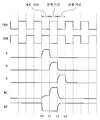
도 10은, 본 실시 형태에 있어서의 i단째의 쌍안정 회로(40(i))의 동작을 설명하기 위한 신호 파형도이다. 또한, 다른 쌍안정 회로도 동일한 동작이므로, 설명을 생략한다. 도 10에서는, 시점 t1부터 시점 t2까지의 기간이 선택 기간에 상당한다. 이하에서는, 선택 기간 직전의 1수평 주사 기간을 「세트 기간」이라고 하고, 선택 기간 직후의 1수평 주사 기간을 「리셋 기간」이라고 한다. 또한, 1수직 주사 기간 중, 스타트 신호(ST)(게이트 스타트 펄스 신호(GSP))가 상승되는 시점부터 엔드 신호(ED)(게이트 앤드 펄스 신호(GEP))가 상승되는 시점까지의 기간을 「기입 기간」이라고 한다. 또한, 1수직 주사 기간 중, 엔드 신호(ED)가 상승되는 시점부터 후속의 수직 주사 기간에서 스타트 신호(ST)가 상승되는 시점까지의 기간(소정 기간)을 「수직 귀선 기간」이라고 한다. 또한, 이 수직 귀선 기간 중, 엔드 신호(ED)가 로우 레벨이 되어 있는 기간을 특히 「휴지 기간」이라고 한다. 또한, 기입 기간 중 선택 기간, 세트 기간 및 리셋 기간 이외의 기간을 「통상 동작 기간」이라고 한다.10 is a signal waveform diagram for explaining the operation of the i-th bistable circuit 40 (i) in the present embodiment. Since other bistable circuits operate in the same manner, a description thereof will be omitted. In Fig. 10, the period from time t1 to time t2 corresponds to the selection period. Hereinafter, one horizontal scanning period immediately before the selection period is referred to as a "set period", and one horizontal scanning period immediately after the selection period is referred to as a "reset period". The period from the rise of the start signal ST (gate start pulse signal GSP) to the rise of the end signal ED (gate and pulse signal GEP) during one vertical scanning period is referred to as " Entry period ". The period (predetermined period) from the time point when the end signal ED rises to the time point when the start signal ST rises in the subsequent vertical scanning period is referred to as a "vertical retrace period" in one vertical scanning period. During this vertical retrace period, the period in which the end signal ED is at the low level is referred to as a " rest period " in particular. A period other than the selection period, the set period and the reset period in the writing period is referred to as a " normal operation period ".
통상 동작 기간(기입 기간에 있어서, 시점 t0 이전의 기간 및 시점 t3 이후의 기간)에서는, 제2 노드(N2)의 전위는 하이 레벨로 유지되어 있다. 이로 인해, 박막 트랜지스터(M5, M6)는 온 상태가 되어 있다. 박막 트랜지스터(M2)의 게이트-드레인간에는 기생 용량이 존재하므로 동작 제어용 클록(CKA)의 파형의 변동(도 10 참조)에 기인하여 제1 노드(N1)에 노이즈가 발생하지만, 박막 트랜지스터(M5)가 온 상태로 되어 있는 점에서 제1 노드(N1)의 전위는 로우 레벨로 인입된다. 또한, 제1 노드(N1)에 발생한 노이즈나 영상 신호 전압의 변동에 기인하여 상태 신호(Q)(출력 단자(51))에도 노이즈가 발생하지만, 박막 트랜지스터(M6)가 온 상태로 되어 있는 점에서 상태 신호(Q)의 전위는 로우 레벨로 인입된다. 이상에서, 이 기간 중, 제1 노드(N1)의 전위 및 상태 신호(Q)의 전위는 로우 레벨에서 유지된다.In the normal operation period (the period before the time point t0 and the time period after the time point t3 in the writing period), the potential of the second node N2 is kept at the high level. As a result, the thin film transistors M5 and M6 are turned on. Noise occurs in the first node N1 due to the fluctuation of the waveform of the operation control clock CKA (see Fig. 10) because the parasitic capacitance exists between the gate and the drain of the thin film transistor M2. However, The potential of the first node N1 is pulled to the low level. Noise is also generated in the state signal Q (output terminal 51) due to the noise generated in the first node N1 or the fluctuation of the video signal voltage. However, when the thin film transistor M6 is in the ON state The potential of the state signal Q enters the low level. Thus, during this period, the potential of the first node N1 and the potential of the status signal Q are maintained at the low level.
통상 동작 기간에서는, 또한, 전하 보충용 클록 신호(CKB)의 전위가 1수평 기간마다 하이 레벨과 로우 레벨을 반복함으로써, 2수평 주사 기간마다의 1수평 기간에서 박막 트랜지스터(M9)가 온 상태가 된다. 이로 인해, 박막 트랜지스터(M9)를 통하여 제2 노드(N2)에 전하가 공급된다. 이에 의해, 박막 트랜지스터(예를 들어, 박막 트랜지스터(M3))에서의 전류의 누설로 인해 제2 노드(N2)의 전위가 저하되어도, 전하 보충용 클록 신호(CKB)가 하이 레벨이 되어 있는 기간에 제2 노드(N2)의 전위가 상승함과 동시에, 콘덴서(C2)가 충전된다. 따라서, 통상 동작 기간에서는 제2 노드(N2)의 전위가 확실하게 하이 레벨에서 유지된다.In the normal operation period, the potential of the charge replenishment clock signal (CKB) repeats a high level and a low level every one horizontal period, so that the thin film transistor M9 is turned on in one horizontal period for every two horizontal scanning periods . As a result, charge is supplied to the second node N2 through the thin film transistor M9. Thus, even if the potential of the second node N2 is lowered due to the leakage of the current in the thin film transistor (for example, the thin film transistor M3), in the period during which the charge replenishment clock signal CKB is at the high level The potential of the second node N2 rises and the capacitor C2 is charged. Therefore, the potential of the second node N2 is reliably maintained at the high level in the normal operation period.
세트 기간이 되면(시점 t0이 되면), 세트 신호(S)가 로우 레벨에서 하이 레벨로 변화한다. 박막 트랜지스터(M1)는 도 7에 도시한 바와 같이 다이오드 접속으로 되어 있으므로, 세트 신호(S)가 하이 레벨이 됨으로써 박막 트랜지스터(M1)는 온 상태가 되고, 콘덴서(C1)가 충전(여기서는 프리차지)된다. 이에 의해, 제1 노드(N1)의 전위는 로우 레벨에서 하이 레벨로 변화하고, 박막 트랜지스터(M2)는 온 상태가 된다. 그러나, 세트 기간에는 동작 제어용 클록 신호(CKA)의 전위가 로우 레벨로 되어 있으므로, 상태 신호(Q)의 전위는 로우 레벨에서 유지된다. 또한, 세트 신호(S)가 하이 레벨이 됨으로써 박막 트랜지스터(M3)가 온 상태가 된다. 이로 인해, 제2 노드(N2)의 전위가 로우 레벨이 된다. 이에 의해, 박막 트랜지스터(M5 및 M6)가 오프 상태가 된다.When the set period (at time point t0), the set signal S changes from the low level to the high level. Since the thin film transistor M1 is diode-connected as shown in Fig. 7, when the set signal S becomes a high level, the thin film transistor M1 is turned on and the capacitor C1 is charged )do. Thereby, the potential of the first node N1 changes from the low level to the high level, and the thin film transistor M2 becomes the on-state. However, since the potential of the operation control clock signal CKA is at the low level during the set period, the potential of the state signal Q is maintained at the low level. Further, when the set signal S becomes a high level, the thin film transistor M3 is turned on. As a result, the potential of the second node N2 becomes low level. As a result, the thin film transistors M5 and M6 are turned off.
선택 기간이 되면(시점 t1이 되면), 세트 신호(S)가 하이 레벨에서 로우 레벨로 변화한다. 이에 의해, 박막 트랜지스터(M1)가 오프 상태가 된다. 이 때, 제2 노드(N2)의 전위는 로우 레벨로 되어 있으므로, 박막 트랜지스터(M5)는 오프 상태가 되어 있다. 따라서, 제1 노드(N1)는 플로팅 상태가 된다. 이 시점 t1에서는 동작 제어용 클록 신호(CKA)의 전위가 로우 레벨에서 하이 레벨로 변화한다. 상술한 바와 같이, 박막 트랜지스터(M2)의 게이트-드레인간에는 기생 용량이 존재하므로, 입력 단자(46)의 전위의 상승에 수반하여 제1 노드(N1)의 전위도 상승한다(제1 노드(N1)가 부트스트랩됨). 그 결과, 박막 트랜지스터(M2)가 완전히 온 상태가 되고, 이 쌍안정 회로의 출력 단자(51)에 접속되어 있는 게이트 라인이 선택 상태가 되므로 충분한 레벨까지 상태 신호(Q)의 전위가 상승한다. 이와 같이, 출력부(63)는 제1 노드(N1) 및 제2 노드(N2)의 전위가 각각 하이 레벨(온 레벨) 및 로우 레벨(오프 레벨)이며, 또한, 제1 구동부(61)가 수취하는 신호(박막 트랜지스터(M1)에 제공되는 신호)인 세트 신호(S)가 로우 레벨(오프 레벨)일 때, 액티브한 상태 신호를 출력한다. 또한, 상태 신호(Q)의 전위가 하이 레벨이 됨으로써 박막 트랜지스터(M4)가 온 상태가 되므로, 제2 노드(N2)의 전위가 확실하게 로우 레벨이 된다. 이에 의해, 선택 기간에서 박막 트랜지스터(M5 및 M6)가 확실하게 오프 상태로 유지된다.When the selection period is reached (at time t1), the set signal S changes from a high level to a low level. As a result, the thin film transistor M1 is turned off. At this time, since the potential of the second node N2 is at a low level, the thin film transistor M5 is turned off. Therefore, the first node N1 becomes a floating state. At this time t1, the potential of the operation control clock signal CKA changes from the low level to the high level. As described above, since the parasitic capacitance exists between the gate and the drain of the thin film transistor M2, the potential of the first node N1 also rises with the rise of the potential of the input terminal 46 (the potential at the first node N1 ) Is bootstrapped). As a result, the thin film transistor M2 is completely turned on, and the gate line connected to the
리셋 기간이 되면(시점 t2가 되면), 동작 제어용 클록 신호(CKA)의 전위가 하이 레벨에서 로우 레벨로 변화한다. 시점 t2에는 박막 트랜지스터(M2)가 온 상태로 되어 있으므로, 입력 단자(46)의 전위의 저하와 함께 상태 신호(Q)의 전위가 저하한다. 이와 같이 상태 신호(Q)의 전위가 저하됨으로써, 콘덴서(C1)를 통하여 제1 노드(N1)의 전위도 저하된다. 또한, 이 기간에는 리셋 신호(R)가 로우 레벨에서 하이 레벨로 변화한다. 이로 인해, 박막 트랜지스터(M7)가 온 상태가 되고, 제2 노드(N2)의 전위가 하이 레벨이 된다. 이에 의해, 박막 트랜지스터(M5 및 M6)가 온 상태가 된다. 그 결과, 리셋 기간에는 제1 노드(N1)의 전위 및 상태 신호(Q)의 전위는 로우 레벨까지 저하된다. 또한, 제2 노드(N2)의 전위의 상승에 수반하여 콘덴서(C2)가 충전되므로, 이 제2 노드(N2)의 전위(하이 레벨)는 이 리셋 기간 후에도 유지된다. 또한, m단째(최후단)의 쌍안정 회로(40(m))에 대해서는, 리셋 기간에 있어서, 엔드 신호(ED)가 로우 레벨에서 하이 레벨로 변화함으로써, 박막 트랜지스터(M5 및 M6)가 온 상태가 된다. 그 결과, m단째의 쌍안정 회로(40(m))에 대해서도, 리셋 기간에는 제1 노드(N1)의 전위 및 상태 신호(Q)의 전위는 로우 레벨까지 저하한다.When the reset period is reached (time t2), the potential of the operation control clock signal CKA changes from high level to low level. Since the thin film transistor M2 is turned on at the time point t2, the potential of the state signal Q decreases with the potential of the
이상, 기입 기간에서의 쌍안정 회로의 동작에 대하여 설명했지만, 수직 귀선 기간에 있어서의 쌍안정 회로의 동작에 대해서는 게이트 드라이버(400)의 상세한 동작과 함께 후술한다.The operation of the bistable circuit in the writing period has been described above. The operation of the bistable circuit in the vertical retrace period will be described later in detail with the operation of the
<1.5 클록 제어 회로의 구성><1.5 Configuration of Clock Control Circuit>
도 11은, 본 실시 형태에 있어서의 클록 제어 회로(420)의 구성을 도시하는 블록도이다. 이 클록 제어 회로(420)는 상술한 바와 같이 게이트 드라이버(400) 내에 설치되어 있다. 도 11에 도시한 바와 같이, 이 클록 제어 회로(420)는 제1 제어 신호 생성 회로(71), 제2 제어 신호 생성 회로(72) 및 클록 출력 회로(73)에 의해 구성되어 있다.11 is a block diagram showing the configuration of the
제1 제어 신호 생성 회로(71)에는, 표시 제어 회로(200)로부터 게이트 스타트 펄스 신호(GSP) 및 게이트 앤드 펄스 신호(GEP)가 제공된다. 이 제1 제어 신호 생성 회로(71)는, 수취한 게이트 스타트 펄스 신호(GSP) 및 게이트 앤드 펄스 신호(GEP)에 기초하여 제1 제어 신호(CT1)를 생성하여 출력한다. 이 제1 제어 신호 생성 회로(71)는, 예를 들어 도 12에 도시한 바와 같이, RS 래치 회로에 의해 실현된다. 이 제1 제어 신호 생성 회로(71)는, 게이트 스타트 펄스 신호(GSP) 및 게이트 앤드 펄스 신호(GEP)를 각각 세트 신호(S) 및 리셋 신호(R)로서 수취하고, 상태 신호(Q)로서 제1 제어 신호(CT1)를 출력한다.The first control
제2 제어 신호 생성 회로(72)에는, 제1 제어 신호 생성 회로(71)로부터 제1 제어 신호(CT1)가 제공됨과 함께, 표시 제어 회로(200)로부터 게이트 스타트 펄스 신호(GSP)가 제공된다. 이 제2 제어 신호 생성 회로(72)는, 수취한 제1 제어 신호(CT1) 및 게이트 스타트 펄스 신호(GSP)에 기초하여 제2 제어 신호(CT2)를 생성하여 출력한다. 이 제2 제어 신호 생성 회로(72)는, 예를 들어 도 13에 도시한 바와 같이, XOR(익스클루시브 오어) 회로에 의해 실현된다. 이 제2 제어 신호 생성 회로(72)는, 제1 제어 신호(CT1) 및 게이트 스타트 펄스 신호(GSP)를 각각 제1 입력 및 제2가 입력으로서 수취하고, 제2 제어 신호(CT2)를 출력한다.The first control signal CT1 is supplied from the first control
클록 출력 회로(73)에는, 표시 제어 회로(200)로부터 제어전 게이트 클록 신호(GCKf)(제어전 제1 게이트 클록 신호(GCKf1) 및 제어전 제2 게이트 클록 신호(GCKf2))가 제공됨과 함께, 제2 제어 신호 생성 회로(72)로부터 제2 제어 신호(CT2)가 제공된다. 이 클록 출력 회로(73)는, 수취한 제어전 게이트 클록 신호(GCKf) 및 제2 제어 신호(CT2)에 기초하여 제어후 게이트 클록 신호(GCK)(제어후 제1 게이트 클록 신호(GCK1) 및 제어후 제2 게이트 클록 신호(GCK2))를 생성하여 출력한다. 이 클록 출력 회로(73)는, 예를 들어 도 14에 도시한 바와 같이, 2개의 AND 회로(73a 및 73b)에 의해 실현된다. 또한, 이하에서는 2개의 AND 회로 중 한쪽인 AND 회로(73a)를 「제1 AND 회로」라고 하고, 다른 쪽인 AND 회로(73b)를 「제2 AND 회로」라고 한다. 제1 AND 회로(73a)는 제어전 제1 게이트 클록 신호(GCKf1) 및 제2 제어 신호(CT2)를 수취하고, 이것들의 논리곱을 제어후 제1 게이트 클록 신호(GCK1)로서 출력한다. 마찬가지로, 제2 AND 회로(73b)는 제어전 제2 게이트 클록 신호(GCKf2) 및 제2 제어 신호(CT2)를 수취하고, 이것들의 논리곱을 제어후 제2 게이트 클록 신호(GCK2)로서 출력한다. 제1 AND 회로(73a) 및 제2 AND 회로(73b)로부터 각각 출력된 제어후 제1 게이트 클록 신호(GCK1) 및 제어후 제2 게이트 클록 신호(GCK2)는 시프트 레지스터(410) 내의 각 쌍안정 회로에 제공된다. 또한, 이상에 나타낸 클록 제어 회로(420)의 구성은 단순한 예시이며, 본 발명은 이것에 한정되지 않는다.The
<1.6 클록 제어 회로의 동작><1.6 Operation of Clock Control Circuit>
도 15는, 본 실시 형태에 있어서의 클록 제어 회로(420)의 동작을 설명하기 위한 신호 파형도이다. 도 15에 도시한 바와 같이, 제어전 제1 게이트 클록 신호(GCK1f) 및 제어전 제2 게이트 클록 신호(GCKf2)는 하이 레벨과 로우 레벨을 주기적으로 반복하고 있다.15 is a signal waveform diagram for explaining the operation of the
우선, 기입 기간이 개시하면(시점 ta가 되면), 게이트 스타트 펄스 신호(GSP)가 로우 레벨에서 하이 레벨로 변화한다. 또한, 게이트 앤드 펄스 신호(GEP)는 로우 레벨이 되어 있다. 이 때, 도 12에 도시하는 제1 제어 신호 생성 회로(71)의 세트 신호는 하이 레벨, 리셋 신호(R)는 로우 레벨이 된다. 이로 인해, 도 15에 도시한 바와 같이, 이 제1 제어 신호 생성 회로(71)의 상태 신호(Q)인 제1 제어 신호(CT1)가 하이 레벨이 된다. 이에 의해, 도 13에 도시하는 제2 제어 신호 생성 회로(72)의 제1 입력은 하이 레벨이 되고, 제2 입력은 하이 레벨이 된다. 따라서, 도 15에 도시한 바와 같이, 이 제2 제어 신호 생성 회로(72)의 출력인 제2 제어 신호(CT2)가 로우 레벨이 된다. 그 결과, 제어후 제1 게이트 클록 신호(GCK1) 및 제어후 제2 게이트 클록 신호(GCK2)가 로우 레벨이 된다. 즉, 이 때, 제어전 게이트 클록 신호(GCKf)의 각 쌍안정 회로에의 공급이 정지된 상태가 되어 있다.First, when the writing period starts (at time point ta), the gate start pulse signal GSP changes from a low level to a high level. In addition, the gate and pulse signal GEP is at a low level. At this time, the set signal of the first control
이어서, 시점 tb가 되면, 게이트 스타트 펄스 신호(GSP)가 하이 레벨에서 로우 레벨로 변화한다. 또한, 게이트 앤드 펄스 신호(GEP)는 로우 레벨이 되어 있다. 이 때, 도 12에 도시하는 제1 제어 신호 생성 회로(71)의 세트 신호는 로우 레벨, 리셋 신호(R)는 로우 레벨이 된다. 이로 인해, 도 15에 도시한 바와 같이, 이 제1 제어 신호 생성 회로(71)의 상태 신호(Q)인 제1 제어 신호(CT1)가, 이전의 상태(시점 ta의 상태)인 하이 레벨을 유지한다. 이에 의해, 도 13에 도시하는 제2 제어 신호 생성 회로(72)의 제1 입력은 하이 레벨이 되고, 제2 입력은 로우 레벨이 된다. 따라서, 도 15에 도시한 바와 같이, 이 제2 제어 신호 생성 회로(72)의 출력인 제2 제어 신호(CT2)가 하이 레벨이 된다. 그 결과, 제어전 제1 게이트 클록 신호(GCKf1) 및 제어전 제2 게이트 클록 신호(GCKf2)가 각각, 제어후 제1 게이트 클록 신호(GCK1) 및 제어후 제2 게이트 클록 신호(GCK2)로서 출력된다. 즉, 이 때, 제어전 게이트 클록 신호(GCKf)가 각 쌍안정 회로에 공급되는 상태로 되어 있다. 이 상태는, 게이트 앤드 펄스 신호(GEP)가 로우 레벨에서 하이 레벨로 변화할 때까지(시점 tc까지) 유지된다.Subsequently, at time tb, the gate start pulse signal GSP changes from a high level to a low level. In addition, the gate and pulse signal GEP is at a low level. At this time, the set signal of the first control
이어서, 시점 tc가 되면, 게이트 앤드 펄스 신호(GEP)가 로우 레벨에서 하이 레벨로 변화한다. 또한, 게이트 스타트 펄스 신호(GSP)는 로우 레벨이 되어 있다. 이 때, 도 12에 도시하는 제1 제어 신호 생성 회로(71)의 세트 신호는 로우 레벨, 리셋 신호(R)는 하이 레벨이 된다. 이로 인해, 도 15에 도시한 바와 같이, 이 제1 제어 신호 생성 회로(71)의 상태 신호(Q)인 제1 제어 신호(CT1)가 로우 레벨이 된다. 이에 의해, 도 13에 도시하는 제2 제어 신호 생성 회로(72)의 제1 입력은 로우 레벨이 되고, 제2 입력은 로우 레벨이 된다. 따라서, 도 15에 도시한 바와 같이, 이 제2 제어 신호 생성 회로(72)의 출력인 제2 제어 신호(CT2)가 로우 레벨이 된다. 그 결과, 제어후 제1 게이트 클록 신호(GCK1) 및 제어후 제2 게이트 클록 신호(GCK2)가 로우 레벨이 된다. 즉, 이 때, 제어전 게이트 클록 신호(GCKf)의 각 쌍안정 회로에의 공급이 정지된 상태로 되어 있다. 이 상태는, 후속의 수직 주사 기간의 기입 기간에서 게이트 스타트 펄스 신호(GSP)가 하이 레벨에서 로우 레벨로 변화할 때까지(시점 td까지) 유지된다.Subsequently, at time tc, the gate and pulse signal GEP changes from a low level to a high level. Also, the gate start pulse signal GSP is at a low level. At this time, the set signal of the first control
이상과 같이, 본 실시 형태에서는, 1수직 주사 기간 중, 게이트 앤드 펄스 신호(GEP)(엔드 신호(ED))가 하강하는 시점부터 후속의 수직 주사 기간에서 게이트 스타트 펄스 신호(GSP)(스타트 신호(ST))가 상승되는 시점까지의 기간인 수직 귀선 기간에 있어서, 제어후 제1 게이트 클록 신호(GCK1) 및 제어후 제2 게이트 클록 신호(GCK2)의 양쪽이 로우 레벨이 된다. 즉, 수직 귀선 기간에서는 제어전 제1 게이트 클록 신호(GCKf1) 및 제어전 제2 게이트 클록 신호(GCKf2)의 각 쌍안정 회로에의 공급이 정지된다. 또한, 이상에 나타낸 클록 제어 회로(420)의 동작은 단순한 예시이며, 본 발명은 이것에 한정되지 않는다.As described above, in this embodiment, in one vertical scanning period, from the time when the gate and pulse signal GEP (end signal ED) falls, to the gate-start pulse signal GSP (start signal Both the first gate clock signal GCK1 after the control and the second gate clock signal GCK2 after the control become the low level in the vertical retrace period which is the period from the start of the control to the rise of the clock signal ST. That is, in the vertical retrace period, the supply of the first gate clock signal GCKf1 before the control and the second gate clock signal GCKf2 before the control is stopped to each bistable circuit. The operation of the
<1.7 게이트 드라이버의 상세한 동작><1.7 Detailed Operation of Gate Driver>
도 16은, 본 실시 형태에 있어서의 게이트 드라이버(400)의 상세한 동작을 설명하기 위한 신호 파형도이다. 본 실시 형태 및 후술하는 각 실시 형태에서는, 1수직 주사 기간을, 일반적인 구동 주파수인 60Hz(약 16.7msec)에서 구동하는 것으로서 설명한다. 도 16에 도시한 바와 같이, 본 실시 형태에서는, 1수직 주사 기간의 약 1/2의 길이인 수직 귀선 기간(약 8.3msec)을 마련하고 있다. 이것에 맞춰서 기입 기간의 구동 주파수를, 일반적인 구동 주파수의 배속인 120Hz(약 8.3msec)로 하고 있다. 즉, 본 실시 형태에서는, 기입 기간의 길이와 수직 귀선 기간의 길이가 서로 거의 동등해져 있다. 또한, 이하에서는, 설명의 편의상, 1단째(40(1)) 내지 m단째(40(m))에서의 제1 노드(N1)를 각각 부호 N1(1) 내지 N1(m)으로 나타내고, 제2 노드(N2)를 각각 부호 N2(1) 내지 N2(m)로 나타낸다. 또한, 제1 노드(N1(1) 내지 N1(m))를 각각 「1단째 제1 노드 내지 m단째 제1 노드」라고 하고, 제2 노드(N2(1) 내지 N2(m))를 각각 「1단째 제2 노드 내지 m단째 제2 노드」라고 한다.16 is a signal waveform diagram for explaining the detailed operation of the
우선, 기입 기간에서의 게이트 드라이버(400)의 동작에 대하여 설명한다. 1단째(40(1))의 세트 기간이 되면, 당해 1단째(40(1))에서의 세트 신호(S)인 게이트 스타트 펄스 신호(GSP)의 전위가 로우 레벨에서 하이 레벨로 변화하므로, 1단째 제1 노드(N1(1))이 프리차지 된다. 또한, 세트 신호(S)가 로우 레벨에서 하이 레벨로 변화하므로, 박막 트랜지스터(M3)가 온 상태가 되고, 1단째 제2 노드(N2(1))가 로우 레벨로 유지된다. 또한, 이 때, 제어후 제1 게이트 클록 신호(GCK1)의 전위 및 제어후 제2 게이트 클록 신호(GCK2)의 전위는 로우 레벨이 되어 있다. 또한, 게이트 스타트 펄스 신호(GSP)의 전위가 로우 레벨에서 하이 레벨로 변화함으로써, 도 7 및 도 8에 도시한 바와 같이, 2단째(40(2)) 내지 m단째(40(m))에서의 박막 트랜지스터(M8)가 온 상태가 된다. 이로 인해, 2단째 제2 노드(N2(2)) 내지 m단째 제2 노드(N2(m))의 전위가 로우 레벨에서 하이 레벨로 변화한다. 이와 같이, 2단째 제2 노드(N2(2)) 내지 m단째 제2 노드(N2(m))의 전위가 하이 레벨이 됨으로써, 2단째 제1 노드(N1(2)) 내지 m단째 제1 노드(N1(m))의 전위를 확실하게 로우 레벨로 유지할 수 있다.First, the operation of the
이어서, 1단째(40(1))의 선택 기간(2단째(40(2))의 세트 기간)이 되면, 당해 1단째(40(1))의 동작 제어용 클록 신호(CKA)인 제어후 제1 게이트 클록 신호(GCK1)의 전위가 로우 레벨에서 하이 레벨로 변화함으로써, 1단째 제1 노드(N1(1))가 부트스트랩된다. 그 결과, 1단째(40(1))의 주사 신호(GOUT(1))의 전위가 하이 레벨(액티브)이 된다. 또한, 2단째(40(2))에 대해서는, 세트 신호(S)인 1단째(40(1))의 주사 신호(GOUT(1))의 전위가 로우 레벨에서 하이 레벨로 변화하므로, 2단째 제1 노드(N1(2))가 프리차지 된다. 또한, 세트 신호(S)가 로우 레벨에서 하이 레벨로 변화하므로, 박막 트랜지스터(M3)가 온 상태가 되고, 2단째 제2 노드(N2(2))의 전위가 하이 레벨에서 로우 레벨로 변화한다.Then, when the selection period of the first stage (40 (1)) (the set period of the second stage 40 (2)) is reached, the operation control clock signal CKA of the
이어서, 1단째(40(1))의 리셋 기간(2단째(40(2))의 선택 기간, 또한, 3단째(40(3))의 세트 기간)이 되면, 당해 1단째(40(1))의 리셋 신호(R)인 2단째(40(2))의 주사 신호선(GOUT(2))의 전위가 로우 레벨에서 하이 레벨로 변화하므로, 1단째 제2 노드(N2(1))의 전위가 로우 레벨에서 하이 레벨로 변화한다. 이에 의해, 1단째 제1 노드(N1(1))의 전위가 하이 레벨에서 로우 레벨로 변화한다. 따라서, 1단째(40(1))의 주사 신호(GOUT(1))의 전위가 하이 레벨에서 로우 레벨로 변화한다. 또한, 1단째 제2 노드(N2(1))의 전위(하이 레벨)는 기입 기간 종료 시점(게이트 앤드 펄스 신호(GEP)가 상승되는 시점)까지 유지된다. 또한, 2단째(40(2))에 대해서는, 동작 제어용 클록 신호(CKA)인 제어후 제2 게이트 클록 신호(GCK2)의 전위가 로우 레벨에서 하이 레벨로 변화함으로써, 2단째 제1 노드(N1(2))가 부트스트랩된다. 그 결과, 2단째(40(2))의 주사 신호선(GOUT(2))의 전위가 하이 레벨(액티브)이 된다. 또한, 3단째에 대해서는, 세트 신호(S)인 2단째(40(2))의 주사 신호(GOUT(2))가 로우 레벨에서 하이 레벨로 변화하므로, 3단째 제1 노드(N1(3))가 프리차지 된다. 또한, 세트 신호(S)가 로우 레벨에서 하이 레벨로 변화하므로, 박막 트랜지스터(M3)가 온 상태가 되고, 3단째 제2 노드(N2(3))의 전위가 하이 레벨에서 로우 레벨로 변화한다.Subsequently, when the reset period of the first stage (40 (1)) (the selection period of the second stage 40 (2) and the set period of the third stage 40 (3)) becomes the
이하, 기입 기간 종료 시점까지, m단째(40(m))를 제외한 각 단에서 1수평 주사 기간마다 동일한 동작이 행해진다. m단째(40(m))에는 상술한 바와 같이 박막 트랜지스터(M7) 및 입력 단자(42)가 설치되어 있지 않다. 이로 인해, m단째(40(m))에 있어서의 주사 신호(GOUT(m))를 하이 레벨에서 로우 레벨로 변화시키기 위한 동작은, 리셋 신호(R) 대신에 엔드 신호(ED)(게이트 앤드 펄스 신호(GEP))에 기초하여 행해진다. 또한, 이하에서는, 각 단의 리셋 기간에서 주사 신호를 하이 레벨에서 로우 레벨로 변화시키기 위한 동작을 「리셋 동작」이라고 한다. m단째(40(m))의 리셋 동작은 수직 귀선 기간 중 최초의 1수평 주사 기간에 행해진다.Hereinafter, until the end of the writing period, the same operation is performed for each horizontal scanning period at each stage excluding the m-th stage (40 (m)). In the m-th stage 40 (m), the thin film transistor M7 and the
이어서, 수직 귀선 기간에서의 게이트 드라이버(400)의 동작에 대하여 설명한다. 우선, 수직 귀선 기간이 되면, 게이트 앤드 펄스 신호(GEP)가 로우 레벨에서 하이 레벨로 변화한다. 이로 인해, 이 게이트 앤드 펄스 신호(GEP)를 엔드 신호(ED)로서 수취하는 각 단에 있어서, 박막 트랜지스터(MA 및 MB)가 온 상태가 된다. 이에 의해, 1단째 제1 노드(N1(1)) 내지 m-1단째 제1 노드(N1(m-1))의 전위가 확실하게 로우 레벨로 유지됨과 함께, 1단째 제2 노드(N2(1)) 내지 m-1단째 제2 노드(N2(m-1))의 전위가 하이 레벨에서 로우 레벨로 변화한다. m단째(40(m))에서는 박막 트랜지스터(MA 및 MB)가 온 상태로 됨으로써, m단째 제1 노드(N1(m))의 전위가 하이 레벨에서 로우 레벨로 변화하므로, 주사 신호(GOUT(m))의 전위가 하이 레벨에서 로우 레벨로 변화한다. 이와 같이, m단째(40(m))에서는 다른 단과 달리 엔드 신호(ED)에 기초하여 리셋 동작이 행해진다. 또한, m단째(40(m))에서는 박막 트랜지스터(MA 및 MB)가 온 상태로 됨으로써, m단째 제2 노드(N2(m))의 전위가 로우 레벨로 유지된다. 이와 같이, 게이트 앤드 펄스 신호(GEP)가 로우 레벨에서 하이 레벨로 변화하면, 모든 단에서의 제1 노드(N1)의 전위 및 제2 노드(N2)의 전위가 로우 레벨이 된다. 또한, 게이트 앤드 펄스 신호(GEP)가 로우 레벨에서 하이 레벨로 변화하면, 상술한 클록 제어 회로(420)에 의해 제어전 제1 게이트 클록 신호(GCKf1) 및 제어전 제2 게이트 클록 신호(GCKf2)의 공급이 정지된다. 즉, 제어후 제1 게이트 클록 신호(GCK1) 및 제어후 제2 게이트 클록 신호(GCK2)의 전위가 로우 레벨이 된다.Next, the operation of the
이어서, 수직 귀선 기간에서 게이트 앤드 펄스 신호(GEP)가 하이 레벨에서 로우 레벨로 변화하면(휴지 기간이 되면), 각 단에서의 박막 트랜지스터(MA 및 MB)가 오프 상태가 된다. 또한, 다른 모든 박막 트랜지스터도 오프 상태가 된다. 이로 인해, 각 단에서 제1 노드(N1) 및 제2 노드(N2)가 플로팅 상태가 된다. 그러나, 수직 귀선 기간에서는 상술한 바와 같이 제어후 제1 게이트 클록 신호(GCK1) 및 제어후 제2 게이트 클록 신호(GCK2)의 전위가 로우 레벨이 되어 있다. 이에 의해, 입력 단자(46)의 전위가 변동하지 않으므로, 당해 입력 단자(46)가 드레인 단자에 접속된 박막 트랜지스터(M2)의 게이트-드레인간의 기생 용량에 기인하는 제1 노드(N1)의 전위 변동이 발생하는 경우는 없다. 마찬가지로, 입력 단자(47)가 드레인 단자에 접속된 박막 트랜지스터(M9)의 게이트-드레인간의 기생 용량에 기인하는 제2 노드(N2)의 전위 변동이 발생하는 경우는 없다. 이와 같이, 다음 수직 주사 기간에서의 기입 기간까지(다음으로 게이트 스타트 펄스 신호(GSP)가 상승될 때까지), 각 단에서의 제1 노드(N1)의 전위 및 제2 노드(N2)의 전위가 확실하게 로우 레벨로 유지된다. 이상과 같은 동작에 의해, 본 실시 형태에서는 m개의 쌍안정 회로에 제공되는 모든 신호의 전위, 각 단에서의 제1 노드(N1)의 전위 및 제2 노드(N2)의 전위가 로우 레벨이 되는 휴지 기간이 마련된다.Subsequently, when the gate and pulse signal GEP changes from the high level to the low level (in the rest period) in the vertical retrace period, the thin film transistors MA and MB in each stage are turned off. Further, all the other thin film transistors are also turned off. As a result, the first node N1 and the second node N2 are in a floating state at each stage. However, in the vertical retrace period, the potentials of the first gate clock signal GCK1 and the second gate clock signal GCK2 after the control are low as described above. The potential of the first node N1 due to the parasitic capacitance between the gate and the drain of the thin film transistor M2 whose
<1.8 효과><1.8 Effect>
본 실시 형태에서는, 이상과 같은 동작에 의해, 각 단에서의 제2 노드(N2)의 전위가 당해 단의 세트 기간 및 선택 기간을 제외한 기입 기간에서 하이 레벨이 됨과 함께, 당해 단의 세트 기간과, 선택 기간과, 상기 휴지 기간을 포함하는 수직 귀선 기간에서 로우 레벨이 된다. 또한, 수직 귀선 기간의 길이가 1수직 주사 기간의 약 1/2이 되어 있다. 이로 인해, 각 단에서의 제2 노드(N2)의 전위의 듀티비가 실질적으로 1/2이 된다. 즉, 박막 트랜지스터(M5)의 게이트 단자 및 박막 트랜지스터(M6)의 게이트 단자에 제공되는 전위의 듀티비가 실질적으로 1/2이 된다. 이에 의해, 이것들의 박막 트랜지스터(M5 및 M6)의 임계값 변동이 억제된다. 따라서, 본 실시 형태에 따르면, 박막 트랜지스터(M5 및 M6)의 신뢰성을 높일 수 있다. 이것들의 박막 트랜지스터(M5 및 M6)의 신뢰성이 높아짐으로써 박막 트랜지스터(M5 및 M6)의 크기를 축소할 수 있다. 이와 같이 박막 트랜지스터(M5 및 M6)의 크기를 축소함으로써 소비 전력을 저감시킬 수 있다. 이상에 의해, 본 실시 형태에 따르면, 소비 전력을 저감시키면서 박막 트랜지스터(M5 및 M6)의 신뢰성을 높일 수 있다. 또한, 박막 트랜지스터(M5 및 M6)의 크기를 축소함으로써 액정 표시 장치의 프레임 면적을 축소할 수 있다.In the present embodiment, the potential of the second node N2 at each stage becomes high level in the writing period excluding the set period and the selection period of the stage by the above-described operation, and at the same time, , A selection period, and a vertical retrace period including the pause period. In addition, the length of the vertical retrace period is about 1/2 of one vertical scanning period. As a result, the duty ratio of the potential of the second node N2 at each stage is substantially halved. That is, the duty ratio of the potential provided to the gate terminal of the thin film transistor M5 and the gate terminal of the thin film transistor M6 is substantially halved. As a result, variations in the threshold voltages of the thin film transistors M5 and M6 are suppressed. Therefore, according to the present embodiment, the reliability of the thin film transistors M5 and M6 can be increased. As the reliability of these thin film transistors M5 and M6 increases, the size of the thin film transistors M5 and M6 can be reduced. Thus, the power consumption can be reduced by reducing the size of the thin film transistors M5 and M6. As described above, according to the present embodiment, it is possible to increase the reliability of the thin film transistors M5 and M6 while reducing power consumption. In addition, the frame area of the liquid crystal display device can be reduced by reducing the size of the thin film transistors M5 and M6.
또한, 본 실시 형태에 따르면, 수직 귀선 기간에 있어서는, 제어전 제1 게이트 클록 신호(GCKf1) 및 제어전 제2 게이트 클록 신호(GCKf2)의 공급이 정지됨으로써, 각 단에서의 제1 노드(N1)의 전위 및 제2 노드(N2)의 전위가 확실하게 로우 레벨로 유지된다. 이로 인해, 각 단에서의 제2 노드(N2)의 전위의 듀티비가 확실하게 종래보다도 저감된다. 이에 의해, 박막 트랜지스터(M5 및 M6)의 임계값 변동을 확실하게 억제함으로써 이것들의 신뢰성을 확실하게 높일 수 있다.According to the present embodiment, in the vertical retrace period, the supply of the first gate clock signal GCKf1 before the control and the second gate clock signal GCKf2 before the control is stopped, so that the first node N1 And the potential of the second node N2 are reliably maintained at a low level. As a result, the duty ratio of the potential of the second node N2 at each stage can surely be reduced as compared with the prior art. As a result, the reliability of the thin film transistors M5 and M6 can surely be increased by reliably suppressing the variation in the threshold value.
또한, 일반적으로, 용량성 부하의 구동에 필요로 하는 소비 전력(W)은 전압(진폭)(V)의 2승과 용량값(C)과 주파수(f)의 곱에 비례한다. 게이트 드라이버에서는, 게이트 단자에 클록 신호가 제공되는 박막 트랜지스터의 수가 많아질수록 상기 용량값(C)이 커진다. 즉, 게이트 드라이버에서는, 게이트 단자에 클록 신호가 제공되는 박막 트랜지스터의 수가 많아질수록 소비 전력(W)이 커진다. 특허문헌 2에 기재된 게이트 드라이버에서는, 직접 또는 다른 트랜지스터를 통하여 게이트 단자에 클록 신호가 제공되는 트랜지스터가, 클록 신호(CK1)에 대해서는 트랜지스터 T4, T5, T9 및 T11의 4개, 클록 신호(CK2)에 대해서는 트랜지스터 T6, T8 및 T10의 3개이다. 이에 비해, 본 실시 형태에서는, 직접 또는 다른 트랜지스터를 통하여 게이트 단자에 클록 신호가 제공되는 트랜지스터가, 동작 제어용 클록 신호(CKA)에 대해서는 박막 트랜지스터 T4의 1개, 전하 보충용 클록 신호(CKB)에 대해서는 박막 트랜지스터 M5, M6 및 M9의 3개이다. 이로 인해, 본 실시 형태에 있어서의 게이트 드라이버(400)의 소비 전력(W)은 특허문헌 2에 기재된 게이트 드라이버의 소비 전력보다도 저감된다.In general, the power consumption W required for driving the capacitive load is proportional to the square of the voltage (amplitude) V and the product of the capacitance value C and the frequency f. In the gate driver, the capacitance value C increases as the number of the thin film transistors provided with the clock signal at the gate terminal increases. That is, in the gate driver, as the number of the thin film transistors provided with the clock signal at the gate terminal increases, the power consumption W increases. In the gate driver described in
또한, 본 실시 형태에 따르면, 수직 귀선 기간의 길이에 맞춰서 기입 기간에서의 구동 주파수를 높게 하고 있다(기입 기간을 짧게 하고 있음), 즉, 제어전 게이트 클록 신호(GCKf)의 주파수를 높게 하고 있으므로, 1수직 주사 기간의 길이는 종래와 변함없다. 이에 의해, 실질적인 구동 주파수를 저하시키지 않고 박막 트랜지스터(M5 및 M6)의 신뢰성을 높일 수 있다.According to the present embodiment, the driving frequency in the writing period is made to be high (shortening the writing period) in accordance with the length of the vertical retrace period, that is, the frequency of the pre-control gate clock signal GCKf is made high , And the length of one vertical scanning period is the same as the conventional one. Thus, the reliability of the thin film transistors M5 and M6 can be enhanced without lowering the actual driving frequency.
또한, 본 실시 형태에 따르면, 클록 제어 회로(420)가 게이트 스타트 펄스 신호(GSP) 및 게이트 앤드 펄스 신호(GEP)에 기초하여 제어전 게이트 클록 신호(GCKf)(제어전 제1 게이트 클록 신호(GCKf1) 및 제어전 제2 게이트 클록 신호(GCKf2))의 쌍안정 회로에의 공급을 제어한다. 이로 인해, 제어전 게이트 클록 신호(GCKf)의 공급의 제어가 확실하게 행해진다. 이에 의해, 회로 동작을 안정시킬 수 있다.In addition, according to the present embodiment, the
또한, 본 실시 형태에 따르면, 박막 트랜지스터(MB)가 각 단에 설치되므로, 수직 귀선 기간의 개시 시에 있어서 각 단의 제2 노드(N2)의 전위가 확실하게 로우 레벨이 된다. 이에 의해, 박막 트랜지스터(M5)의 게이트 단자 및 박막 트랜지스터(M6)의 게이트 단자에 제공되는 전위의 듀티비가 확실하게 저감됨과 함께, 회로 동작이 안정된다.Further, according to the present embodiment, since the thin film transistor MB is provided at each stage, the potential of the second node N2 at each stage is surely low level at the start of the vertical retrace period. As a result, the duty ratio of the potential provided to the gate terminal of the thin film transistor M5 and the gate terminal of the thin film transistor M6 is surely reduced, and the circuit operation is stabilized.
또한, 본 실시 형태에 따르면, 박막 트랜지스터(MA)가 각 단에 설치되므로, 수직 귀선 기간의 개시 시에 있어서 각 단의 제1 노드(N1)의 전위가 확실하게 로우 레벨이 된다. 이에 의해, 박막 트랜지스터(M5)의 게이트 단자 및 박막 트랜지스터(M6)의 게이트 단자에 제공되는 전위의 듀티비가 보다 확실하게 저감됨과 함께, 회로 동작이 더욱 안정된다.Further, according to the present embodiment, since the thin film transistor MA is provided at each stage, the potential of the first node N1 at each stage is surely low level at the start of the vertical retrace period. As a result, the duty ratio of the potential provided to the gate terminal of the thin film transistor M5 and the gate terminal of the thin film transistor M6 is more reliably reduced, and the circuit operation becomes more stable.
또한, 본 실시 형태에 따르면, 박막 트랜지스터(M4)가 설치되므로, 선택 기간에서 제2 노드(N2)의 전위가 확실하게 로우 레벨이 된다. 이에 의해, 회로 동작이 더욱 안정된다.Further, according to the present embodiment, since the thin film transistor M4 is provided, the potential of the second node N2 in the selection period surely becomes low level. Thereby, the circuit operation becomes more stable.
<1.9 제1 변형예><1.9 First Modified Example>
도 17은, 상기 제1 실시 형태의 제1 변형예에 있어서의 1단째(최전단) 및 m단째(최후단) 이외의 쌍안정 회로의 구성을 도시하는 회로도이다. 도 18은, 본 변형예에 있어서의 1단째(최전단)의 쌍안정 회로의 구성을 도시하는 회로도이다. 상기 제1 실시 형태에서는 각 단에서 박막 트랜지스터(MA)가 설치되어 있었지만, 본 변형예에서는, 도 17 및 도 18에 도시한 바와 같이, 1단째(40(1)) 내지 m-1단째(40(m-1))에 박막 트랜지스터(MA)가 설치되어 있지 않다. 수직 귀선 기간의 개시 시에는, 도 16에 도시한 바와 같이 1단째 제1 노드(N1(1)) 내지 m-1단째 제1 노드(N1(m-1))의 전위는 로우 레벨이 되어 있으므로, 1단째(40(1)) 내지 m-1단째(40(m-1))에 박막 트랜지스터(MA)를 설치하지 않는 형태에 있어서도, 수직 귀선 기간에서 1단째 제1 노드(N1(1)) 내지 m-1단째 제1 노드(N1(m-1))의 전위를 로우 레벨로 할 수 있다. 또한, 본 변형예에 있어서의 m단째(40(m))에 대해서는, 상기 제1 실시 형태와 마찬가지로 박막 트랜지스터(MA)가 설치되어 있다. 본 변형예에 따르면, 박막 트랜지스터의 수가 저감되므로, 소비 전력을 더욱 저감시킴과 함께, 게이트 드라이버(400)를 구비하는 액정 표시 장치의 프레임 면적을 더욱 축소할 수 있다.17 is a circuit diagram showing a configuration of a bistable circuit other than the first stage (the front end) and the m-th stage (the rear stage) in the first modification of the first embodiment. Fig. 18 is a circuit diagram showing the configuration of the first stage (front-end) bistable circuit in this modification. Though the thin film transistor MA is provided at each stage in the first embodiment, as shown in Figs. 17 and 18, in this modified example, the first stage (40 (1)) to the m- (m-1)) is not provided with the thin film transistor MA. At the start of the vertical blanking period, the potentials of the first node N1 (1) to the (m-1) th first node N1 (m-1) in the first stage are at a low level Stage thin film transistor MA is not provided in the first stage (40 (1)) to the (m-1) th stage 40 (m-1) ) To the (m-1) th first node N1 (m-1) can be set to the low level. In addition, the m-th stage 40 (m) in this modification is provided with a thin film transistor MA similarly to the first embodiment. According to this modification, since the number of thin film transistors is reduced, the power consumption can be further reduced, and the frame area of the liquid crystal display device including the
<1.10 제2 변형예><1.10 Second Modified Example>
도 19는, 상기 제1 실시 형태의 제2 변형예에 있어서의 게이트 드라이버(400)의 상세한 동작을 설명하기 위한 신호 파형도이다. 상기 제1 실시 형태에서는, 1수직 주사 기간을 구동 주파수 60Hz(약 16.7msec)에서 구동하고 있었지만, 본 변형예에서는, 도 19에 도시한 바와 같이, 1수직 주사 기간을 구동 주파수 30Hz(약 33.3msec)에서 구동하고 있다. 예를 들어, 기입 기간의 구동 주파수를 60Hz(약 16.7msec)로 하면, 수직 귀선 기간의 길이가 수직 주사 기간의 길이의 약 1/2인 약 16.7msec가 된다. 이 경우, 각 단에서의 제2 노드(N2)의 전위의 듀티비가 실질적으로 1/2이 되므로, 상기 제1 실시 형태와 동일한 효과가 얻어진다.19 is a signal waveform diagram for explaining the detailed operation of the
또한, 본 변형예에 있어서 기입 기간의 구동 주파수를 120Hz(약 8.3msec)로 하면, 수직 귀선 기간의 길이가 수직 주사 기간의 길이의 약 3/4인 약 25msec이 된다. 이 경우, 수직 귀선 기간의 길이가 기입 기간의 길이의 약 3배가 되므로, 각 단에서의 제2 노드(N2)의 전위의 듀티비가 실질적으로 1/4이 된다. 따라서, 박막 트랜지스터(M5 및 M6)의 임계값 변동이 더욱 억제된다.In this modification, when the driving frequency of the writing period is 120 Hz (about 8.3 msec), the length of the vertical retrace period becomes about 25 msec which is about 3/4 of the length of the vertical scanning period. In this case, since the length of the vertical retrace period is about three times the length of the write period, the duty ratio of the potential of the second node N2 at each end is substantially 1/4. Therefore, the threshold variation of the thin film transistors M5 and M6 is further suppressed.
<1.11 제3 변형예><1.11 Third Modified Example>
도 20은, 상기 제1 실시 형태의 제3 변형예에 있어서의 게이트 드라이버(400)의 상세한 동작을 설명하기 위한 신호 파형도이다. 상기 제1 실시 형태에서는 1수직 주사 기간을 구동 주파수 60Hz(약 16.7msec)에서 구동하고 있었지만, 본 변형예에서는, 도 20에 도시한 바와 같이, 1수직 주사 기간을 구동 주파수 15Hz(약 66.6msec)에서 구동하고 있다. 예를 들어, 기입 기간의 구동 주파수를 상기 제2 변형예와 동일하게 60Hz(약 16.7msec)로 하면, 수직 귀선 기간의 길이가 수직 주사 기간의 길이의 약 3/4인 약 50msec이 된다. 이 경우, 수직 귀선 기간의 길이가 기입 기간의 길이의 약 3배가 되므로, 각 단에서의 제2 노드(N2)의 전위의 듀티비가 실질적으로 1/4이 된다. 따라서, 박막 트랜지스터(M5 및 M6)의 임계값 변동이 상기 제1 실시 형태보다도 억제된다.20 is a signal waveform diagram for explaining the detailed operation of the
또한, 본 변형예에 있어서 기입 기간의 구동 주파수를 120Hz(약 8.3msec)로 하면, 수직 귀선 기간의 길이가 수직 주사 기간의 길이의 약 7/8인 약 58.3msec이 된다. 이 경우, 수직 귀선 기간의 길이가 기입 기간의 길이의 약 7배가 되므로, 각 단에서의 제2 노드(N2)의 전위의 듀티비가 실질적으로 1/8이 된다. 따라서, 박막 트랜지스터(M5 및 M6)의 임계값 변동이 더욱 억제된다.In this modification, when the driving frequency of the writing period is 120 Hz (about 8.3 msec), the length of the vertical retrace period is about 58.3 msec, which is about 7/8 of the length of the vertical scanning period. In this case, since the length of the vertical retrace period is about 7 times the length of the write period, the duty ratio of the potential of the second node N2 at each end is substantially 1/8. Therefore, the threshold variation of the thin film transistors M5 and M6 is further suppressed.
<1.12 제4 변형예><1.12 Fourth Modified Example>
도 21은, 상기 제1 실시 형태의 제4 변형예에 있어서의 1단째(최전단) 및 m단째(최후단) 이외의 쌍안정 회로의 구성을 도시하는 회로도이다. 상기 제1 실시 형태에서는 각 단에서 박막 트랜지스터(M3 및 M4)가 설치되어 있었지만, 본 변형예에서는, 도 21에 도시한 바와 같이, 이들 박막 트랜지스터(M3 및 M4) 대신에 박막 트랜지스터(M10)가 설치되어 있다. 또한, 1단째(최전단) 및 m단째(최후단)에 대해서도 마찬가지이므로, 그것들에 대한 설명 및 도시는 생략한다. 이 박막 트랜지스터(M10)에 대해서는, 게이트 단자가 제1 노드(N1)에 접속되고, 드레인 단자가 제2 노드에 접속되고, 소스 단자가 직류 전원 전위(Vss)용의 입력 단자에 접속되어 있다. 이 박막 트랜지스터(M10)는, 제1 노드(N1)의 전위가 하이 레벨이 되어 있을 때, 제2 노드(N2)의 전위를 Vss 전위를 향하여 변화시킨다. 본 변형예에 있어서는, 박막 트랜지스터(M10)에 의해 제2 노드 턴오프용 스위칭 소자가 실현되어 있다. 본 변형예에 따르면, 박막 트랜지스터(M3 및 M4) 대신에 박막 트랜지스터(M10)를 각 쌍안정 회로에 설치함으로써, 세트 기간 및 선택 기간에서 제2 노드(N2)의 전위를 확실하게 로우 레벨로 유지할 수 있다.21 is a circuit diagram showing a configuration of a bistable circuit other than the first stage (the front end) and the m-th stage (the rear stage) in the fourth modification of the first embodiment. In the first embodiment, the thin film transistors M3 and M4 are provided at each stage. In this modification, a thin film transistor M10 is used instead of these thin film transistors M3 and M4 as shown in Fig. Is installed. The same applies to the first stage (the front end) and the m-th stage (the rear stage), and therefore, explanations and illustration thereof are omitted. For this thin film transistor M10, the gate terminal is connected to the first node N1, the drain terminal is connected to the second node, and the source terminal is connected to the input terminal for the DC power source potential Vss. This thin film transistor M10 changes the potential of the second node N2 toward the Vss potential when the potential of the first node N1 is at the high level. In this modification, the switching element for the second node turn-off is realized by the thin film transistor M10. According to this modification, by providing the thin film transistor M10 in each bistable circuit instead of the thin film transistors M3 and M4, the potential of the second node N2 can be reliably maintained at a low level in the set period and the selected period .
<2. 제2 실시 형태><2. Second Embodiment>
<2.1 게이트 드라이버의 상세한 동작><Detailed operation of gate driver>
도 22는, 본 발명의 제2 실시 형태에서의 게이트 드라이버(400)의 상세한 동작을 설명하기 위한 신호 파형도이다. 또한, 액정 표시 장치의 전체 구성 및 동작과, 게이트 드라이버(400)의 구성과, 쌍안정 회로의 구성 및 동작과, 클록 제어 회로(420)의 구성 및 동작에 대해서서는, 본 실시 형태는 상기 제1 실시 형태와 동일하므로 이것들의 설명을 생략한다.22 is a signal waveform diagram for explaining the detailed operation of the
상기 제1 실시 형태에서는, 1수직 주사 기간의 약 1/2의 길이의 수직 귀선 기간(약 8.3msec)을 마련함과 함께, 기입 기간의 구동 주파수를 일반적인 구동 주파수(60Hz)의 배속인 120Hz(약 8.3msec)로 하고 있다. 이에 비해, 본 실시 형태에서는, 도 22에 도시한 바와 같이, 1수직 주사 기간의 약 2/3의 길이의 수직 귀선 기간(약 11.1msec)을 마련함과 함께, 기입 기간의 구동 주파수를 일반적인 구동 주파수의 3배속인 180Hz(약 5.6msec)로 하고 있다. 즉, 본 실시 형태에서는, 수직 귀선 기간의 길이가 기입 기간의 길이의 약 2배로 되어 있다. 또한, 본 실시 형태에 있어서의 기입 기간 및 수직 귀선 기간의 동작은, 상기 제1 실시 형태에 있어서의 것과 동일하므로, 설명을 생략한다.In the first embodiment, a vertical retrace period (about 8.3 msec) having a length of about 1/2 of one vertical scanning period is provided, and a driving frequency of the writing period is set to 120 Hz (approx. 8.3 msec). In contrast, in the present embodiment, as shown in Fig. 22, a vertical retrace period (about 11.1 msec) having a length of about 2/3 of one vertical scanning period is provided, and a drive frequency of the write period is set to a normal drive frequency (About 5.6 msec), which is three times faster than the speed of the motor. That is, in this embodiment, the length of the vertical retrace period is about twice the length of the write period. The operation of the writing period and the vertical retrace period in the present embodiment is the same as that in the first embodiment, and a description thereof will be omitted.
<2.2 효과><Effect of 2.2>
본 실시 형태에서는, 각 단에서의 제2 노드(N2)의 전위가, 당해 단의 세트 기간 및 선택 기간을 제외한 기입 기간에서 하이 레벨이 됨과 함께, 당해 단의 세트 기간과, 선택 기간과, 상기 휴지 기간을 포함하는 수직 귀선 기간에서 로우 레벨이 된다. 또한, 본 실시 형태에서는, 수직 귀선 기간의 길이가 기입 기간의 길이의 약 2배로 되어 있다. 이로 인해, 각 단에서의 제2 노드(N2)의 전위의 듀티비가 실질적으로 1/3이 된다. 즉, 박막 트랜지스터(M5)의 게이트 단자 및 박막 트랜지스터(M6)의 게이트 단자에 제공되는 전위의 듀티비가 실질적으로 1/3이 된다. 따라서, 본 실시 형태에 따르면, 박막 트랜지스터(M5 및 M6)의 임계값 변동이 상기 제1 실시 형태에 비해 더욱 억제된다. 이로 인해, 박막 트랜지스터(M5 및 M6)의 신뢰성이 더욱 높아지므로, 당해 박막 트랜지스터의 크기를 더욱 작게 할 수 있다. 이와 같이 박막 트랜지스터(M5 및 M6)의 크기를 작게 한 경우에는, 소비 전력을 더욱 저감시킴과 함께, 게이트 드라이버(400)를 구비하는 액정 표시 장치의 프레임 면적을 더욱 축소할 수 있다.In the present embodiment, the potential of the second node N2 at each stage becomes a high level in the write period excluding the set period and the selection period of the stage, and the set period, the selection period, And becomes a low level in a vertical retrace period including a rest period. In the present embodiment, the length of the vertical retrace period is about twice the length of the write period. As a result, the duty ratio of the potential of the second node N2 at each stage is substantially 1/3. That is, the duty ratio of the potential provided to the gate terminal of the thin film transistor M5 and the gate terminal of the thin film transistor M6 is substantially 1/3. Therefore, according to the present embodiment, the threshold variation of the thin film transistors M5 and M6 is further suppressed as compared with the first embodiment. As a result, the reliability of the thin film transistors M5 and M6 is further increased, so that the size of the thin film transistor can be further reduced. When the size of the thin film transistors M5 and M6 is reduced in this manner, the power consumption can be further reduced and the frame area of the liquid crystal display device including the
<3. 제3 실시 형태><3. Third Embodiment>
<3.1 게이트 드라이버의 상세한 동작><Detailed Operation of Gate Driver>
도 23은, 본 발명의 제3 실시 형태에 있어서의 게이트 드라이버(400)의 상세한 동작을 설명하기 위한 신호 파형도이다. 또한, 액정 표시 장치의 전체 구성 및 동작과, 게이트 드라이버(400)의 구성과, 쌍안정 회로의 구성 및 동작과, 클록 제어 회로(420)의 구성 및 동작에 대해서서는, 본 실시 형태는 상기 제1 실시 형태와 동일하므로 이것들의 설명을 생략한다.23 is a signal waveform diagram for explaining the detailed operation of the
상기 제1 실시 형태에서는, 1수직 주사 기간의 약 1/2의 길이의 수직 귀선 기간(약 8.3msec)을 마련함과 함께, 기입 기간의 구동 주파수를 일반적인 구동 주파수(60Hz)의 배속인 120Hz(약 8.3msec)로 하고 있다. 또한, 상기 제2 실시 형태에서는, 1수직 주사 기간의 약 2/3의 길이의 수직 귀선 기간(약 11.1msec)을 마련함과 함께, 기입 기간의 구동 주파수를 일반적인 구동 주파수의 3배속인 180Hz(약 5.6msec)로 하고 있다. 이것들에 비하여, 본 실시 형태에서는, 1수직 주사 기간의 약 3/4의 길이의 수직 귀선 기간(약 12.5msec)을 마련함과 함께, 기입 기간의 구동 주파수를 일반적인 구동 주파수의 4배속인 240Hz(약 4.2msec)로 하고 있다. 즉, 본 실시 형태에서는, 수직 귀선 기간의 길이가 기입 기간의 길이의 약 3배로 되어 있다. 또한, 본 실시 형태에 있어서의 기입 기간 및 수직 귀선 기간의 동작은 상기 제1 실시 형태에 있어서의 것과 동일하므로, 설명을 생략한다.In the first embodiment, a vertical retrace period (about 8.3 msec) having a length of about 1/2 of one vertical scanning period is provided, and a driving frequency of the writing period is set to 120 Hz (approx. 8.3 msec). In the second embodiment, a vertical retrace period (about 11.1 msec) having a length of about two-thirds of one vertical scanning period is provided, and a driving frequency of the writing period is set to 180 Hz (about three times the normal driving frequency 5.6 msec). In contrast, in the present embodiment, a vertical retrace period (about 12.5 msec) having a length of about 3/4 of one vertical scanning period is provided, and the drive frequency of the write period is set to 240 Hz 4.2 msec). That is, in this embodiment, the length of the vertical retrace period is about three times the length of the write period. Since the operation of the writing period and the vertical retrace period in this embodiment is the same as that in the first embodiment, the description is omitted.
<3.2 효과><3.2 Effect>
본 실시 형태에서는, 상기 제1 실시 형태와 마찬가지로, 각 단에서의 제2 노드(N2)의 전위가, 당해 단의 세트 기간 및 선택 기간을 제외한 기입 기간에서 하이 레벨이 됨과 함께, 당해 단의 세트 기간과, 선택 기간과, 상기 휴지 기간을 포함하는 수직 귀선 기간에서 로우 레벨이 된다. 또한, 본 실시 형태에서는, 수직 귀선 기간의 길이가 기입 기간의 길이의 약 3배로 되어 있다. 이로 인해, 각 단에서의 제2 노드(N2)의 전위의 듀티비가 실질적으로 1/4이 된다. 즉, 박막 트랜지스터(M5)의 게이트 단자 및 박막 트랜지스터(M6)의 게이트 단자에 제공되는 전위의 듀티비가 실질적으로 1/4이 된다. 따라서, 본 실시 형태에 따르면, 박막 트랜지스터(M5 및 M6)의 임계값 변동이 상기 제2 실시 형태에 비해 더욱 억제된다. 이로 인해, 박막 트랜지스터의 신뢰성이 더욱 높아지므로, 당해 박막 트랜지스터의 크기를 더욱 작게 할 수 있다. 그 결과, 소비 전력을 더욱 저감시킴과 함께, 게이트 드라이버(400)를 구비하는 액정 표시 장치의 프레임 면적을 더욱 축소할 수 있다.In this embodiment, similarly to the first embodiment, the potential of the second node N2 at each stage becomes a high level in the writing period excluding the set period and the selection period of the stage, Period, the selection period, and the vertical retrace period including the pause period. In the present embodiment, the length of the vertical retrace period is about three times the length of the write period. As a result, the duty ratio of the potential of the second node N2 at each stage becomes substantially 1/4. That is, the duty ratio of the potential provided to the gate terminal of the thin film transistor M5 and the gate terminal of the thin film transistor M6 is substantially 1/4. Therefore, according to the present embodiment, the threshold variation of the thin film transistors M5 and M6 is further suppressed as compared with the second embodiment. As a result, the reliability of the thin film transistor is further increased, so that the size of the thin film transistor can be further reduced. As a result, the power consumption can be further reduced, and the frame area of the liquid crystal display device including the
<4. 제4 실시 형태><4. Fourth Embodiment>
<4.1 게이트 드라이버의 상세한 동작><4.1 Detailed Operation of Gate Driver>
도 24는, 본 발명의 제4 실시 형태에 있어서의 게이트 드라이버(400)의 상세한 동작을 설명하기 위한 신호 파형도이다. 또한, 액정 표시 장치의 전체 구성 및 동작과, 게이트 드라이버(400)의 구성과, 쌍안정 회로의 구성 및 동작과, 클록 제어 회로(420)의 구성 및 동작에 대해서서는, 본 실시 형태는 상기 제1 실시 형태와 동일하므로 이것들의 설명을 생략한다.24 is a signal waveform diagram for explaining the detailed operation of the
상기 제1 실시 형태에서는, 1수직 주사 기간의 약 1/2의 길이의 수직 귀선 기간(약 8.3msec)을 마련함과 함께, 기입 기간의 구동 주파수를 일반적인 구동 주파수(60Hz)의 배속인 120Hz(약 8.3msec)로 하고 있다. 이에 비해, 본 실시 형태에서는, 도 24에 도시한 바와 같이, 1수직 주사 기간의 약 1/3의 길이의 수직 귀선 기간(약 5.6msec)을 마련함과 함께, 기입 기간의 구동 주파수를 일반적인 구동 주파수의 1.5배속인 90Hz(약 11.1msec)로 하고 있다. 즉, 본 실시 형태에서는, 수직 귀선 기간의 길이가 기입 기간의 길이의 약 1/2배로 되어 있다. 또한, 본 실시 형태에 있어서의 기입 기간 및 수직 귀선 기간의 동작은, 상기 제1 실시 형태에 있어서의 것과 동일하므로, 설명을 생략한다.In the first embodiment, a vertical retrace period (about 8.3 msec) having a length of about 1/2 of one vertical scanning period is provided, and a driving frequency of the writing period is set to 120 Hz (approx. 8.3 msec). In contrast, in the present embodiment, as shown in Fig. 24, a vertical retrace period (about 5.6 msec) having a length of about 1/3 of one vertical scanning period is provided, and a drive frequency of the write period is set to a normal drive frequency (About 11.1 msec), which is 1.5 times the speed of the optical disk. That is, in the present embodiment, the length of the vertical retrace period is about 1/2 of the length of the write period. The operation of the writing period and the vertical retrace period in the present embodiment is the same as that in the first embodiment, and a description thereof will be omitted.
<4.2 효과><Effect of 4.2>
본 실시 형태에서는, 각 단에서의 제2 노드(N2)의 전위가, 당해 단의 세트 기간 및 선택 기간을 제외한 기입 기간에서 하이 레벨이 됨과 함께, 당해 단의 세트 기간과, 선택 기간과, 상기 휴지 기간을 포함하는 수직 귀선 기간에서 로우 레벨이 된다. 또한, 본 실시 형태에서는, 수직 귀선 기간의 길이가 기입 기간의 길이의 약 1/2배로 되어 있다. 이로 인해, 각 단에서의 제2 노드(N2)의 전위의 듀티비가 실질적으로 2/3가 된다. 즉, 박막 트랜지스터(M5)의 게이트 단자 및 박막 트랜지스터(M6)의 게이트 단자에 제공되는 전위의 듀티비가 실질적으로 2/3가 된다. 이에 의해, 박막 트랜지스터(M5 및 M6)의 임계값 변동이 종래보다도 억제된다. 또한, 본 실시 형태에 있어서의 기입 기간의 구동 주파수는, 상기 제1 실시 형태에 있어서의 것보다도 저속이 된다. 그 결과, 소비 전력이 더욱 저감됨과 함께, 회로 동작이 더욱 안정된다. 따라서, 본 실시 형태에 따르면, 소비 전력을 더욱 저감시킴과 함께 회로 동작을 더욱 안정시키면서 박막 트랜지스터의 신뢰성을 종래보다도 높일 수 있다.In the present embodiment, the potential of the second node N2 at each stage becomes a high level in the write period excluding the set period and the selection period of the stage, and the set period, the selection period, And becomes a low level in a vertical retrace period including a rest period. In the present embodiment, the length of the vertical retrace period is about 1/2 times the length of the write period. As a result, the duty ratio of the potential of the second node N2 at each stage becomes substantially 2/3. That is, the duty ratio of the potential provided to the gate terminal of the thin film transistor M5 and the gate terminal of the thin film transistor M6 is substantially 2/3. Thereby, the variation in the threshold value of the thin film transistors M5 and M6 is suppressed as compared with the prior art. The driving frequency in the writing period in the present embodiment is lower than that in the first embodiment. As a result, the power consumption is further reduced and the circuit operation becomes more stable. Therefore, according to the present embodiment, the reliability of the thin film transistor can be further increased as compared with the conventional one, while the power consumption is further reduced and the circuit operation is further stabilized.
<5. 제5 실시 형태><5. Fifth Embodiment>
<5.1 게이트 드라이버의 전원 투입 후의 동작><5.1 Operation after power on of gate driver>
도 25는, 본 발명의 제5 실시 형태에 있어서의 게이트 드라이버(400)에서의 전원 투입 후부터 최초의 수직 주사 기간의 개시 시점(게이트 스타트 펄스 신호(GSP)가 최초에 로우 레벨에서 하이 레벨로 변화하는 시점)까지의 동작을 설명하기 위한 신호 파형도이다. 또한, 액정 표시 장치의 전체 구성 및 동작과, 게이트 드라이버(400)의 구성 및 전원 투입 직후 이외의 동작과, 쌍안정 회로의 구성 및 동작과, 클록 제어 회로(420)의 구성 및 동작에 대해서서는, 본 실시 형태는 상기 제1 실시 형태와 동일하므로 이것들의 설명을 생략한다.Fig. 25 is a timing chart for explaining the start point of the first vertical scanning period after the power is turned on in the
도 25에 도시한 바와 같이, 전원 투입 직후부터, 제어전 제1 게이트 클록 신호(GCKf1) 및 제어전 제2 게이트 클록 신호(GCKf2)의 게이트 드라이버(400)(클록 출력 회로(73))에의 공급이 개시된다. 본 실시 형태에서는, 전원 투입 후 직후에 게이트 앤드 펄스 신호(GEP)의 전위가 로우 레벨에서 하이 레벨로 변화한다. 이 때, 게이트 스타트 펄스 신호(GSP)의 전위는 로우 레벨이다. 이로 인해, 도 12에 도시하는 제1 제어 신호 생성 회로(71)의 세트 신호는 로우 레벨, 리셋 신호(R)는 하이 레벨이 되고, 이 제1 제어 신호 생성 회로(71)의 상태 신호(Q)인 제1 제어 신호(CT1)가 로우 레벨이 된다. 이에 의해, 도 13에 도시하는 제2 제어 신호 생성 회로(72)의 제1 입력은 로우 레벨이 되고, 제2 입력은 로우 레벨이 되고, 이 제2 제어 신호 생성 회로(72)의 출력인 제2 제어 신호(CT2)가 로우 레벨이 된다. 그 결과, 제어후 제1 게이트 클록 신호(GCK1) 및 제어후 제2 게이트 클록 신호(GCK2)가 로우 레벨이 된다. 즉, 이 때, 제어전 게이트 클록 신호(GCKf)의 각 쌍안정 회로에의 공급이 정지된 상태로 되어 있다. 이 상태는, 최초의 수직 주사 기간의 기입 기간에서 게이트 스타트 펄스 신호(GSP)가 하이 레벨에서 로우 레벨로 변화할 때까지 유지된다.As shown in Fig. 25, supply from the immediately after power-on to the gate driver 400 (clock output circuit 73) of the pre-control first gate clock signal GCKf1 and the pre-control second gate clock signal GCKf2 / RTI > In the present embodiment, the potential of the gate and pulse signal GEP changes from a low level to a high level immediately after power-on. At this time, the potential of the gate start pulse signal GSP is at a low level. This causes the set signal of the first control
또한, 전원 투입 직후에 게이트 앤드 펄스 신호(GEP)의 전위가 로우 레벨에서 하이 레벨로 변화할 때, 이 게이트 앤드 펄스 신호(GEP)를 엔드 신호(ED)로서 수취하는 각 단에서 박막 트랜지스터(MA 및 MB)가 온 상태가 된다. 이에 의해, 1단째 제1 노드(N1(1)) 내지 m단째 제1 노드(N1(m))의 전위가 로우 레벨로 리셋됨과 함께, 1단째 제2 노드(N2(1)) 내지 m단째 제2 노드(N2(m))의 전위가 로우 레벨로 리셋된다.In addition, when the potential of the gate and pulse signal GEP changes from the low level to the high level immediately after the power supply is turned on, in each stage that receives the gate and pulse signal GEP as the end signal ED, And MB are turned on. As a result, the potentials of the first node N1 (1) to the m-th first node N1 (m) are reset to the low level and the potentials of the first node N2 (1) The potential of the second node N2 (m) is reset to the low level.
<5.2 효과><5.2 Effect>
본 실시 형태에 따르면, 전원 투입 후부터 최초의 수직 주사 기간의 개시 시점까지의 기간에서 불안정해지는 제1 노드(N1)의 전위 및 제2 노드(N2)의 전위가 로우 레벨로 리셋된다. 또한, 전원 투입 후부터 최초의 수직 주사 기간의 개시 시점까지의 기간에는 제어전 게이트 클록 신호(GCKf)의 각 쌍안정 회로에의 공급이 정지된 상태가 된다. 이로 인해, 제1 노드(N1)의 전위 및 제2 노드(N2)의 전위가 확실하게 로우 레벨로 유지된다. 이에 의해, 회로 동작을 더욱 안정시킬 수 있다.According to the present embodiment, the potential of the first node N1 and the potential of the second node N2, which become unstable in the period from the power-on to the start of the first vertical scanning period, are reset to the low level. In addition, the supply of the control gate clock signal GCKf to each bistable circuit is stopped during the period from the power-on to the start of the first vertical scanning period. As a result, the potential of the first node N1 and the potential of the second node N2 are reliably maintained at a low level. Thereby, the circuit operation can be further stabilized.
또한, 전원 투입 후부터 최초의 수직 주사 기간의 개시 시점까지의 기간에 있어서는, 게이트 앤드 펄스 신호(GEP) 대신에 전원 투입 직후에 로우 레벨에서 하이 레벨로 변화하는 다른 신호를 사용해도 된다.In the period from the power-on to the start of the first vertical scanning period, other signals that change from low level to high level immediately after power-on may be used instead of the gate and pulse signal (GEP).
<6. 제6 실시 형태><6. Sixth Embodiment >
<6.1 시프트 레지스터의 구성 및 동작><6.1 Configuration and Operation of Shift Register>
도 26은, 본 발명의 제6 실시 형태에 있어서의 시프트 레지스터(410)의 최전단 및 최후단 이외의 구성을 도시하는 블록도이다. 도 27은, 본 실시 형태에 있어서의 시프트 레지스터(410)의 최전단측의 구성을 도시하는 블록도이다. 도 28은, 본 실시 형태에 있어서의 시프트 레지스터(410)의 최후단측의 구성을 도시하는 블록도이다. 또한, 액정 표시 장치의 전체 구성 및 동작과, 클록 제어 회로(420)의 구성 및 동작에 대해서서는, 본 실시 형태는 상기 제1 실시 형태와 동일하므로 이것들의 설명을 생략한다.26 is a block diagram showing the configuration other than the forefront and the rearmost stages of the
도 26 내지 도 28에 도시한 바와 같이, 본 실시 형태에 있어서의 각 쌍안정 회로에는, 상기 제1 실시 형태에 있어서의 각 쌍안정 회로와 달리 전하 보충용 클록 신호(CKB)를 수취하기 위한 입력 단자가 설치되어 있지 않다. 본 실시 형태에 있어서의 홀수단째에는, 제어후 제1 게이트 클록 신호(GCK1)가 동작 제어용 클록 신호(CKA)로서 제공되고, 본 실시 형태에 있어서의 짝수단째에는, 제어후 제2 게이트 클록 신호(GCK2)가 동작 제어용 클록 신호(CKA)로서 제공된다. 또한, 본 실시 형태에 있어서의 각 쌍안정 회로의 그 밖의 단자(입력 단자 및 출력 단자)는, 상기 제1 실시 형태의 각 쌍안정 회로에 있어서의 것과 동일하다. 또한, 본 실시 형태에 있어서의 게이트 드라이버(400)의 기본적인 동작은, 상기 제1 실시 형태에 있어서의 게이트 드라이버(400)의 것과 동일하므로, 설명을 생략한다.As shown in Figs. 26 to 28, each of the bistable circuits in the present embodiment is different from the bistable circuits in the first embodiment in that the input terminal for receiving the charge complementary clock signal (CKB) Is not installed. In the odd-numbered stages in the present embodiment, the first gate clock signal GCK1 after the control is provided as the operation control clock signal CKA, and the even-numbered stages in the present embodiment are provided with the second gate clock signal GCK2 are provided as the operation control clock signal CKA. The other terminals (input terminal and output terminal) of each bistable circuit in the present embodiment are the same as those in the respective bistable circuits of the first embodiment. The basic operation of the
<6.2 쌍안정 회로의 구성><6.2 Construction of bistable circuit>
도 29는, 본 실시 형태에 있어서의 1단째(최전단) 및 m단째(최후단) 이외의 쌍안정 회로의 구성을 도시하는 회로도이다. 도 29에 도시한 바와 같이, 이 쌍안정 회로는, 상술한 특허문헌 1에 기재된 쌍안정 회로(도 32)에 박막 트랜지스터(M8, MA 및 MB)를 추가한 것이다. 또한, 본 실시 형태에 있어서의 쌍안정 회로에는, 상기 제1 실시 형태에 있어서의 쌍안정 회로와 달리 박막 트랜지스터(M4 및 M9)가 설치되어 있지 않다. 이 쌍안정 회로에는, 로우 레벨의 직류 전원 전위(Vss)용의 입력 단자 이외에 5개의 입력 단자(41 내지 44 및 46)와 1개의 출력 단자(51)가 설치되어 있다. 상술한 바와 같이, 이 쌍안정 회로에는 전하 보충용 클록 신호(CKB)를 수취하기 위한 입력 단자(47)가 설치되어 있지 않다.29 is a circuit diagram showing the configuration of a bistable circuit other than the first stage (the front end) and the m-th stage (the rear stage) in the present embodiment. As shown in Fig. 29, this bistable circuit is obtained by adding thin film transistors M8, MA and MB to the bistable circuit (Fig. 32) described in
제1 구동부(61)는, 상기 제1 실시 형태에 있어서의 것과 마찬가지로, 3개의 박막 트랜지스터(M1, M5 및 MA)에 의해 구성되어 있다. 제2 구동부(62)는, 4개의 박막 트랜지스터(M3, M4, M8, M9 및 MB)와, 1개의 콘덴서(C2)에 의해 구성되어 있다. 출력부(63)는, 상기 제1 실시 형태에 있어서의 것과 마찬가지로, 2개의 박막 트랜지스터(M2 및 M6)와, 1개의 콘덴서(C1)에 의해 구성되어 있다.The
제1 구동부(61) 내에 설치된 박막 트랜지스터(M1)의 소스 단자, 박막 트랜지스터(M5)의 드레인 단자 및 박막 트랜지스터(MA)의 드레인 단자는 제1 노드(N1)에 접속되어 있다. 제2 구동부(62) 내에 설치된 박막 트랜지스터(M3)의 드레인 단자, 박막 트랜지스터(M7)의 소스 단자, 박막 트랜지스터(M8)의 소스 단자, 박막 트랜지스터(MB)의 드레인 단자, 콘덴서(C2)의 일단부는 제2 노드(N2)에 접속되어 있다. 출력부(63) 내에 설치된 박막 트랜지스터(M2)의 게이트 단자 및 콘덴서(C1)의 일단부가 제1 노드(N1)에 접속되고, 박막 트랜지스터(M6)의 게이트 단자가 제2 노드(N2)에 접속되어 있다. 또한, 각 박막 트랜지스터 및 각 콘덴서의 접속 및 기능에 대해서는, 상기 제1 실시 형태에 있어서의 것과 동일하므로, 설명을 생략한다.The source terminal of the thin film transistor M1, the drain terminal of the thin film transistor M5 and the drain terminal of the thin film transistor MA provided in the
도 30은, 본 실시 형태에 있어서의 1단째(최전단)의 쌍안정 회로의 구성을 도시하는 회로도이다. 도 30에 도시한 바와 같이, 이 쌍안정 회로에는, 도 29에 도시하는 1단째(최전단) 및 m단째(최후단) 이외의 쌍안정 회로와 달리 박막 트랜지스터(M8) 및 입력 단자(44)가 설치되어 있지 않다. 또한, 이 쌍안정 회로의 그 밖의 구성은, 도 29에 도시하는 1단째(최전단) 및 m단째(최후단) 이외의 쌍안정 회로의 것과 동일하므로, 그 설명을 생략한다.30 is a circuit diagram showing the configuration of a first stage (front-end) bistable circuit in the present embodiment. As shown in Fig. 30, the bistable circuit includes a thin film transistor M8 and an
도 31은, 본 실시 형태에 있어서의 m단째(최후단)의 쌍안정 회로의 구성을 도시하는 회로도이다. 도 31에 도시한 바와 같이, 이 쌍안정 회로에는, 도 29에 도시하는 1단째(최전단) 및 m단째(최후단) 이외의 쌍안정 회로와 달리 박막 트랜지스터(M7) 및 입력 단자(42)가 설치되어 있지 않다. 또한, 이 쌍안정 회로의 그 밖의 구성은, 도 29에 도시하는 1단째(최전단) 및 m단째(최후단) 이외의 쌍안정 회로의 것과 동일하므로, 그 설명을 생략한다.31 is a circuit diagram showing the configuration of a m-th stage (last stage) bistable circuit in the present embodiment. As shown in Fig. 31, the bistable circuit includes a thin film transistor M7 and an
본 실시 형태에 있어서도, 상기 제1 실시 형태와 마찬가지로, 박막 트랜지스터(M1)에 의해 제1 노드 턴온용 스위칭 소자가 실현되고, 박막 트랜지스터(M2)에 의해 출력 제어용 스위칭 소자가 실현되고, 박막 트랜지스터(M3)에 의해 제1 제2 노드 턴오프용 스위칭 소자가 실현되고, 박막 트랜지스터(M5)에 의해 제1 노드 턴오프용 스위칭 소자가 실현되고, 박막 트랜지스터(M6)에 의해 출력 노드 턴오프용 스위칭 소자가 실현되고, 박막 트랜지스터(M7)에 의해 제2 노드 턴온용 스위칭 소자가 실현되고, 박막 트랜지스터(M8)에 의해 스타트용 스위칭 소자가 실현되고, 박막 트랜지스터(MA)에 의해 제1 엔드용 스위칭 소자가 실현되고, 박막 트랜지스터(MB)에 의해 제2 엔드용 스위칭 소자가 실현되어 있다. 또한, 콘덴서(C1)에 의해 용량 소자가 실현되어 있다.Also in this embodiment, similarly to the first embodiment, the first node turn-on switching element is realized by the thin film transistor M1, the output control switching element is realized by the thin film transistor M2, The switching element for turning off the first node is realized by the thin film transistor M3, the switching element for turning off the first node is realized by the thin film transistor M5, The switching element for turning on the second node is realized by the thin film transistor M7, the switching element for starting is realized by the thin film transistor M8, and the switching for the first end is performed by the thin film transistor MA. Device is realized, and the switching element for the second end is realized by the thin film transistor MB. Further, a capacitor element is realized by the capacitor C1.
<6.3 쌍안정 회로의 동작><6.3 Operation of bistable circuit>
본 실시 형태에 있어서의 쌍안정 회로의 기본적인 동작은, 상기 제1 실시 형태에 있어서의 것과 동일하다. 따라서, 본 실시 형태 및 상기 제1 실시 형태에 서로 공통되는 동작의 설명은 생략하고, 서로의 상위점만에 대하여 상기 도 10을 참조하면서 설명한다.The basic operation of the bistable circuit in this embodiment is the same as that in the first embodiment. Therefore, the description of the operations common to the present embodiment and the first embodiment will be omitted, and only the differences between them will be described with reference to FIG.
상기 제1 실시 형태에서는, 통상 동작 기간(기입 기간에 있어서, 시점 t0 이전의 기간 및 시점 t3 이후의 기간)에 있어서, 전하 보충용 클록 신호(CKB)의 전위가 1수평 기간마다 하이 레벨과 로우 레벨을 반복함으로써, 2수평 주사 기간마다의 1수평 기간에서 박막 트랜지스터(M9)가 온 상태가 된다. 이로 인해, 박막 트랜지스터(M9)를 통하여 제2 노드(N2)에 전하가 공급된다. 이에 의해, 통상 동작 기간에서는 제2 노드(N2)의 전위가 확실하게 하이 레벨로 유지된다. 이에 비해, 본 실시 형태에서는, 전하 보충용 클록 신호(CKB)를 수취하기 위한 입력 단자(47) 및 박막 트랜지스터(M9)가 설치되어 있지 않으므로, 상기 제1 실시 형태와 같이, 통상 동작 기간에서 제2 노드(N2)에 전하가 공급되는 경우는 없다. 따라서, 통상 동작 기간에 있어서의 제2 노드(N2)의 전위의 안정성에 대해서는, 본 실시 형태는 종래의 것과 다름없다.In the first embodiment, the potential of the charge replenishment clock signal (CKB) is set to the high level and the low level (one level) during one horizontal period in the normal operation period (the period before the time point t0 and the time period after the time point t3 in the writing period) The thin film transistor M9 is turned on in one horizontal period every two horizontal scanning periods. As a result, charge is supplied to the second node N2 through the thin film transistor M9. Thus, the potential of the second node N2 is reliably maintained at the high level in the normal operation period. In contrast to this, in the present embodiment, since the
또한, 상기 제1 실시 형태에서는, 선택 기간이 되면(시점 t1이 되면), 상태 신호(Q)의 전위가 하이 레벨이 됨으로써 박막 트랜지스터(M4)가 온 상태가 된다. 이로 인해, 선택 기간에서 제2 노드(N2)의 전위가 확실하게 로우 레벨이 된다. 이에 비해, 본 실시 형태에서는, 박막 트랜지스터(M4)가 설치되어 있지 않으므로, 이러한 선택 기간에서 제2 노드(N2)의 전위를 확실하게 로우 레벨로 하기 위한 동작이 이루어지지 않는다. 따라서, 선택 기간에서의 제2 노드(N2)의 전위에 대해서는, 본 실시 형태는 종래의 것과 다름없다.In the first embodiment, in the selection period (when the time t1 is reached), the potential of the state signal Q becomes high level, whereby the thin film transistor M4 is turned on. This ensures that the potential of the second node N2 in the selection period becomes a low level. In contrast, in the present embodiment, since the thin film transistor M4 is not provided, an operation for reliably bringing the potential of the second node N2 to a low level in such a selection period is not performed. Therefore, regarding the potential of the second node N2 in the selection period, the present embodiment is the same as the conventional one.
또한, 본 실시 형태에 있어서의 게이트 드라이버의 상세한 동작에 대해서도, 상술한 통상 동작 기간 및 선택 기간에서의 제2 노드(N2)의 전위가 불안정해지기 쉬운 점을 제외하고, 상기 제1 실시 형태에 있어서의 것과 동일하므로, 설명을 생략한다. 이와 같이, 본 실시 형태에서는, 상기 제1 실시 형태보다도 통상 동작 기간 및 선택 기간에서의 제2 노드(N2)의 전위가 불안정해지므로, 제1 노드(N1)의 전위 및 상태 신호(Q)(주사 신호)의 전위에 노이즈가 발생하기 쉬워진다. 즉, 본 실시 형태에서는 회로 동작이 불안정해지기 쉽다.The detailed operation of the gate driver in this embodiment is also similar to the first embodiment except that the potential of the second node N2 tends to become unstable in the normal operation period and the selection period described above And therefore, a description thereof will be omitted. As described above, in this embodiment, since the potential of the second node N2 in the normal operation period and the selection period becomes unstable as compared with the first embodiment, the potential of the first node N1 and the potential of the state signal Q Noise is likely to occur at the potential of the scanning signal. That is, the circuit operation tends to become unstable in the present embodiment.
<6.4 효과><6.4 Effect>
그러나, 본 실시 형태에 따라서도, 박막 트랜지스터(M5 및 M6)의 임계값 변동이 종래보다도 억제됨과 함께, 소스 단자에 클록 신호가 제공되는 박막 트랜지스터의 수가 종래보다도 적어진다. 그 결과, 소비 전력을 저감시키면서 박막 트랜지스터(M5 및 M6)의 신뢰성을 높일 수 있다. 게다가, 본 실시 형태에 따르면, 상기 제1 실시 형태와 마찬가지로, 박막 트랜지스터(M5 및 M6)의 신뢰성이 높아짐으로써 이것들의 박막 트랜지스터(M5 및 M6)의 크기를 작게 할 수 있다. 이와 같이 박막 트랜지스터(M5 및 M6)의 크기를 작게 한 경우에는, 소비 전력이 더욱 저감됨과 함께, 게이트 드라이버(400)를 구비한 액정 표시 장치의 프레임 면적을 축소할 수 있다.However, according to the present embodiment, the variation in the threshold value of the thin film transistors M5 and M6 is suppressed as compared with the prior art, and the number of thin film transistors provided with the clock signal at the source terminal is smaller than in the prior art. As a result, reliability of the thin film transistors M5 and M6 can be increased while reducing power consumption. In addition, according to the present embodiment, as in the first embodiment, reliability of the thin film transistors M5 and M6 is increased, so that the sizes of the thin film transistors M5 and M6 can be reduced. When the size of the thin film transistors M5 and M6 is reduced in this manner, the power consumption is further reduced and the frame area of the liquid crystal display device provided with the
또한, 상기 제1 실시 형태의 변형예와 같이, 1단째(40(1)) 내지 m-1단째(40(m-1))에 박막 트랜지스터(MA)를 설치하지 않는 형태로 해도 된다. 이 경우, 박막 트랜지스터의 수가 더욱 저감되므로, 소비 전력을 더욱 저감시킴과 함께, 게이트 드라이버(400)를 구비하는 액정 표시 장치의 프레임 면적을 더욱 축소할 수 있다.The thin film transistor MA may not be provided in the first stage (40 (1)) to the (m-1) th stage 40 (m-1) as in the modification of the first embodiment. In this case, since the number of the thin film transistors is further reduced, the power consumption can be further reduced and the frame area of the liquid crystal display device including the
<7. 기타><7. Other>
본 발명에 있어서의 게이트 드라이버(400)의 구성은, 상기 각 실시 형태에 있어서의 것에 한정되지 않는다. 즉, 게이트 드라이버(400)가, 각 쌍안정 회로 내에 적어도 박막 트랜지스터(M5 및 M6)를 구비하고, 2수평 주사 기간보다도 긴 수직 귀선 기간을 마련함과 함께, 이 수직 귀선 기간에서 각 쌍안정 회로에의 클록 신호의 공급을 정지시키고, 또한, 이 수직 귀선 기간에 있어서, 상기 박막 트랜지스터(M5)의 드레인 단자에 접속된 제1 노드의 전위와 상기 박막 트랜지스터(M5 및 M6)의 게이트 단자에 접속된 제2 노드(N2)의 전위를 오프 레벨로 유지하는 구성으로 되어 있으면 된다. 예를 들어, 상기 제2 종래예에 있어서, 상기 제1 실시 형태에 있어서의 박막 트랜지스터(M8, MA 및 MB)를 추가한 구성으로 해도 된다. 또한, 상기 제2 종래예에서는, 트랜지스터(T4 및 T5)가 본 발명에 있어서의 박막 트랜지스터(M5 및 M6)에 상당한다. 또한, 입력부(920)에 의해 제1 구동부(61)가 실현되고, 풀 다운 구동부(940)에 의해 제2 구동부(62)가 실현되어, 출력부(450)에 의해 출력부(63)가 실현되어 있다. 이러한 형태에 있어서, 기입 기간의 길이 및 수직 귀선 기간의 길이를 상기 제1 실시 형태에 있어서의 것과 동일하게 하면, 제2 노드(N2)가 접속된 트랜지스터(T4 및 T5)의 게이트 단자에는 듀티비가 실질적으로 1/4의 전위가 제공되게 된다. 이에 의해, 이러한 형태에 있어서는, 트랜지스터(T4 및 T5)에 발생하는 임계값 변동을 상기 제2 종래예보다도 억제할 수 있다. 단, 이러한 형태에서는, 제2 노드(N2)의 전위가 기입 기간에서의 듀티비 1/2(기입 기간의 길이 및 수직 귀선 기간의 길이를, 상기 제1 실시 형태에 있어서의 것과 동일하게 하면 1/4)이 되므로, 이 제2 노드(N2)의 전위 변동에 기인하는 노이즈가 제1 노드N2의 전위 및 상태 신호(Q)의 전위에 발생한다. 따라서, 회로 동작의 안정성에 대해서는, 상기 제1 실시 형태의 것보다도 뒤떨어진다.The configuration of the
상기 각 실시 형태에서는, 수직 귀선 기간에서 각 쌍안정 회로에의 클록 신호의 공급을 정지시키고 있지만, 본 발명은 이것에 한정되지 않는다. 수직 귀선 기간에서 각 쌍안정 회로에의 클록 신호의 공급을 정지시키지 않아도, 트랜지스터(M5 및 M6)의 임계값 변동을 종래보다도 억제할 수 있다.In each of the above embodiments, the supply of the clock signal to each bistable circuit is stopped in the vertical retrace period, but the present invention is not limited to this. The threshold value fluctuation of the transistors M5 and M6 can be suppressed as compared with the prior art even if the supply of the clock signal to each bistable circuit is not stopped in the vertical retrace period.
상기 제1 내지 4의 실시 형태에서는, 수직 귀선 기간의 길이를 각각 1수직 주사 기간의 길이의 약 1/2, 약 2/3, 약 3/4 및 약 1/3로 하고 있다. 이와 같이, 박막 트랜지스터의 신뢰성을 높이는 관점에서 수직 귀선 기간의 길이는 충분히 긴 것이 바람직하다.In the first to fourth embodiments, the length of the vertical retrace period is set to about 1/2, about 2/3, about 3/4 and about 1/3 of the length of one vertical scanning period, respectively. Thus, from the viewpoint of enhancing the reliability of the thin film transistor, the length of the vertical retrace period is preferably long enough.
상기 각 실시 형태 및 각 변형예에서 나타낸 구동 주파수는 예시이며, 다양한 변경이 가능하다.The driving frequencies shown in the above-described embodiments and modified examples are merely examples, and various modifications are possible.
상기 각 실시 형태에서는, 클록 제어 회로(420)에 의해 클록 신호의 쌍안정 회로에의 공급의 제어를 행하고 있지만, 본 발명은 이것에 한정되지 않는다. 예를 들어, 상술한 클록 제어 회로(420)를 게이트 드라이버(400) 내에 설치하지 않고, 표시 제어 회로(200)가 상술한 제어후 제1 게이트 클록 신호(GCK1) 및 제어후 제2 게이트 클록 신호(GCK2)에 상당하는 클록 신호를 직접 생성하여 쌍안정 회로에 공급하도록 해도 된다.In each of the above embodiments, the
상기 각 실시 형태에 있어서의 클록 제어 회로(420)는, 게이트 스타트 펄스 신호(GSP) 및 게이트 앤드 펄스 신호(GEP)에 기초하여 제어전 게이트 클록 신호(GCKf)의 공급을 제어하고 있지만, 본 발명은 이것에 한정되지 않는다. 미리 수직 귀선 기간의 길이가 결정되어 있는 경우에는, 게이트 스타트 펄스 신호(GSP) 대신에 수직 귀선 기간의 길이만 지연한 게이트 앤드 펄스 신호(GEP)를, 상기 제1 제어 신호 생성 회로(71) 및 제2 제어 신호 생성 회로(72)에 제공하도록 해도 된다. 또한, 상기 클록 제어 회로(420)의 구성은 특별히 한정되지 않는다.Although the
상기 각 실시 형태에서는, 게이트 드라이버(400) 내에 1개의 클록 제어 회로(420)가 설치되어 있지만, 본 발명은 이것에 한정되지 않는다. 예를 들어, 각 쌍안정 회로 내에 상기 클록 제어 회로(420)에 상당하는 회로가 설치되어 있어도 된다.In each of the above-described embodiments, one
상기 각 실시 형태에서는, 쌍안정 회로 내에 설치되어 있는 박막 트랜지스터는 모두 n채널형인 것으로서 설명했지만, 본 발명은 이것에 한정되지 않는다. 쌍안정 회로 내에 설치되어 있는 박막 트랜지스터가 p채널형이어도 본 발명을 적용할 수 있다.In the above embodiments, the thin film transistors provided in the bistable circuit are all of the n-channel type, but the present invention is not limited to this. The present invention can be applied even if the thin film transistor provided in the bistable circuit is of the p-channel type.
상기 각 실시 형태에서는 액정 표시 장치를 예로 들어 설명했지만, 본 발명은 이것에 한정되지 않는다. 유기 EL(Electro Luminescence) 표시 장치 등의 다른 표시 장치에도 본 발명을 적용할 수 있다. 또한, 그 밖에 본 발명의 취지를 일탈하지 않는 범위에서 상기 각 실시 형태를 여러가지 변형하여 실시할 수 있다.Although the liquid crystal display device has been described as an example in each of the above embodiments, the present invention is not limited to this. The present invention can also be applied to other display devices such as organic EL (Electro Luminescence) display devices. The above-described embodiments can be modified in various ways within the scope not departing from the gist of the present invention.
이상에 의해, 본 발명에 따르면, 소비 전력을 저감시키면서 스위칭 소자의 신뢰성을 높인 주사 신호선 구동 회로, 그것을 구비한 표시 장치 및 주사 신호선의 구동 방법을 제공할 수 있다.As described above, according to the present invention, it is possible to provide a scanning signal line driving circuit which increases the reliability of the switching element while reducing power consumption, a display device including the same, and a method of driving the scanning signal line.
본 발명은 주사 신호선 구동 회로, 그것을 구비한 표시 장치 및 그 주사 신호선 구동 회로에 의한 주사 신호선의 구동 방법에 적용할 수 있고, 특히, 모놀리식화된 주사 신호선 구동 회로, 그것을 구비한 표시 장치 및 그 주사 신호선 구동 회로에 의한 주사 신호선의 구동 방법에 적합하다.The present invention can be applied to a scanning signal line driving circuit, a display device having the same, and a method of driving a scanning signal line by the scanning signal line driving circuit. More particularly, the present invention relates to a monolithic scanning signal line driving circuit, And is suitable for a method of driving a scanning signal line by a scanning signal line driving circuit.
40(1) 내지 40(m) : 쌍안정 회로
41 내지 44, 46, 47 : 입력 단자
51 : 출력 단자(출력 노드)
61 : 제1 구동부
62 : 제2 구동부
63 : 출력부
71 : 제1 제어 신호 생성 회로
72 : 제2 제어 신호 생성 회로
73 : 클록 출력 회로
73a : 제1 AND 회로
73b : 제2 AND 회로
200: 표시 제어 회로
300 : 소스 드라이버(영상 신호선 구동 회로)
400 : 게이트 드라이버(주사 신호선 구동 회로)
410 : 시프트 레지스터
420 : 클록 제어 회로
600 : 표시부
C1, C2 : 콘덴서(용량 소자)
M1 내지 M10, MA, MB : 박막 트랜지스터(스위칭 소자)
N1 : 제1 노드
N2 : 제2 노드
GCKf1 : 제어전 제1 게이트 클록 신호
GCKf2 : 제어전 제2 게이트 클록 신호
GCK1 : 제어후 제1 게이트 클록 신호
GCK2 : 제어후 제2 게이트 클록 신호
GSP : 게이트 스타트 펄스 신호
GEP : 게이트 앤드 펄스 신호
CKA : 동작 제어용 클록 신호
CKB : 전하 보충용 클록 신호
S : 세트 신호
R : 리셋 신호
ST : 스타트 신호
ED : 엔드 신호
GOUT(1) 내지 GOUT(m) : 주사 신호
Vss : 로우 레벨의 직류 전원 전위40 (1) to 40 (m): a bistable circuit
41 to 44, 46, 47: input terminal
51: Output terminal (output node)
61:
62:
63: Output section
71: first control signal generation circuit
72: second control signal generation circuit
73: Clock output circuit
73a: first AND circuit
73b: a second AND circuit
200: display control circuit
300: source driver (video signal line driving circuit)
400: Gate driver (scanning signal line driving circuit)
410: Shift register
420: Clock control circuit
600:
C1, C2: Capacitor (Capacitor)
M1 to M10, MA, MB: Thin film transistors (switching elements)
N1: First node
N2: second node
GCKf1: First gate clock signal before control
GCKf2: second gate clock signal before control
GCK1: First gate clock signal after control
GCK2: second gate clock signal after control
GSP: Gate start pulse signal
GEP: gate and pulse signal
CKA: clock signal for operation control
CKB: charge complementary clock signal
S: set signal
R: Reset signal
ST: Start signal
ED: end signal
GOUT (1) to GOUT (m): scan signals
Vss: Low-level DC power source potential
Claims (25)
서로 종속 접속된 복수의 쌍안정 회로를 포함하고, 외부로부터 입력되어 온 레벨과 오프 레벨을 주기적으로 반복하는 클록 신호에 기초하여 상기 복수의 쌍안정 회로의 출력 신호를 순차적으로 액티브로 하는 시프트 레지스터를 포함하고,
각 쌍안정 회로는,
제1 노드와,
제2 노드와,
상기 제1 노드에 접속되고, 전단의 쌍안정 회로로부터 출력되는 출력 신호가 오프 레벨로부터 온 레벨로 변화한 때에 상기 제1 노드의 전위를 오프 레벨로부터 온 레벨로 변화시키고, 상기 제2 노드의 전위가 오프 레벨로부터 온 레벨로 변화한 때에 상기 제1 노드의 전위를 온 레벨로부터 오프 레벨로 변화시키는 제1 구동부와,
상기 제2 노드에 접속되고, 다음단의 쌍안정 회로로부터 출력되는 출력 신호가 오프 레벨로부터 온 레벨로 변화한 때에 상기 제2 노드의 전위를 오프 레벨로부터 온 레벨로 변화시키고, 전단의 쌍안정 회로로부터 출력되는 출력 신호 또는 상기 제1 노드의 전위가 오프 레벨로부터 온 레벨로 변화한 때에 상기 제2 노드의 전위를 온 레벨로부터 오프 레벨로 변화시키는 제2 구동부와,
상기 제1 노드 및 상기 제2 노드에 접속되고, 상기 제1 노드의 전위 및 상기 제2 노드 전위가 각각 온 레벨 및 오프 레벨이며, 또한, 상기 제1 구동부가 수취한 전단의 쌍안정 회로로부터 출력되는 출력 신호의 전위가 오프 레벨일 때, 액티브한 상기 출력 신호를 상기 클록 신호에 기초하여 출력하는 출력부를 포함하고,
상기 제1 구동부는, 상기 제2 노드가 제어 단자에 접속되고, 상기 제1 노드가 한쪽 도통 단자에 접속되고, 오프 레벨의 전위가 다른 쪽의 도통 단자에 제공된 제1 노드 턴오프용 스위칭 소자를 포함하고,
상기 출력부는, 상기 제2 노드가 제어 단자에 접속되고, 상기 출력 신호를 출력하기 위한 출력 노드가 한쪽 도통 단자에 접속되고, 오프 레벨의 전위가 다른 쪽의 도통 단자에 제공된 출력 노드 턴오프용 스위칭 소자를 포함하고,
상기 제1 구동부 및 상기 제2 구동부가, 각 수직 주사 기간 중 2수평 주사 기간 이상의 소정 기간에서 상기 제1 노드의 전위 및 상기 제2 노드의 전위를 각각 오프 레벨로 유지하는 것을 특징으로 하는 주사 신호선 구동 회로.A scanning signal line driving circuit for driving a plurality of scanning signal lines,
A shift register including a plurality of bistable circuits cascade-connected to each other and sequentially activating output signals of the plurality of bistable circuits based on a clock signal periodically repeating a level input from the outside and an off level, Including,
Each bistable circuit comprises:
A first node,
A second node,
And changes the potential of the first node from the off level to the on level when the output signal output from the bistable circuit at the previous stage changes from the off level to the on level, A first driving unit for changing the potential of the first node from the on level to the off level when the potential of the first node changes from the off level to the on level,
And changes the potential of the second node from the off level to the on level when the output signal output from the next stage bistable circuit changes from the off level to the on level, A second driving unit for changing the potential of the second node from the ON level to the OFF level when the potential of the first node changes from the OFF level to the ON level,
Wherein the first node and the second node are connected to each other, the potential of the first node and the potential of the second node are on level and off level, respectively, and the output from the bistable circuit And an output section for outputting the active output signal based on the clock signal when the potential of the output signal to be activated is off level,
The first driver may include a first node turn-off switching element having the second node connected to the control terminal, the first node connected to one of the conduction terminals, and the off-level potential provided to the other conduction terminal Including,
The output node is connected to the control terminal, the output node for outputting the output signal is connected to one of the conduction terminals, and the off-state potential is supplied to the other conduction terminal for the output node turn- Device,
Wherein the first driver and the second driver respectively maintain the potential of the first node and the potential of the second node at an off level in a predetermined period longer than two horizontal scanning periods in each vertical scanning period, Drive circuit.
전원 투입 후부터 최초의 수직 주사 기간의 개시까지의 동안에 또한, 상기 복수의 쌍안정 회로에의 상기 클록 신호의 공급이 정지되는 것을 특징으로 하는 주사 신호선 구동 회로.The display device according to claim 2, wherein the first driving unit and the second driving unit are configured to turn off the potential of the first node and the potential of the second node from off to on during the period from power-on to the start of the first vertical scanning period However,
Wherein supply of the clock signal to the plurality of bistable circuits is stopped during a period from power-on to the start of the first vertical scanning period.
각 쌍안정 회로에 있어서의 상기 제2 구동부는, 상기 엔드 신호가 제어 단자에 제공되고, 상기 제2 노드가 한쪽 도통 단자에 접속되고, 오프 레벨의 전위가 다른 쪽의 도통 단자에 제공된 제2 엔드용 스위칭 소자를 포함하는 것을 특징으로 하는 주사 신호선 구동 회로.6. The bistable circuit according to claim 5, wherein the first driving unit in the final-stage bistable circuit is configured such that the end signal is provided to the control terminal, the first node is connected to one conduction terminal, Further comprising a switching element for a first end provided in a conduction terminal,
Wherein the second driving unit in each bistable circuit is configured such that the end signal is provided to the control terminal, the second node is connected to one conducting terminal, and the off-level potential is supplied to the other conducting terminal And a scanning signal line driving circuit for driving the scanning signal line.
최전단의 쌍안정 회로에 있어서의 상기 세트 신호는 상기 스타트 신호이며,
최전단 이외의 쌍안정 회로에 있어서의 상기 세트 신호는 상기 쌍안정 회로의 전단의 쌍안정 회로의 출력 신호인 것을 특징으로 하는 주사 신호선 구동 회로.9. The semiconductor memory device according to claim 8, wherein the first driver further comprises a first node turn-on switching element for changing the potential of the first node toward the on level based on the set signal,
The set signal in the bistable circuit at the foremost stage is the start signal,
And said set signal in a bistable circuit other than the most front stage is an output signal of a bistable circuit in the preceding stage of said bistable circuit.
상기 제1 노드가 제어 단자에 접속되고, 상기 클록 신호가 한쪽 도통 단자에 제공되고, 상기 출력 노드가 다른 쪽의 도통 단자에 접속된 출력 제어용 스위칭 소자와,
상기 출력 제어용 스위칭 소자의 상기 제어 단자가 일단부에 접속되고, 상기 출력 노드가 타단부에 접속된 용량 소자를 더 포함하는 것을 특징으로 하는 주사 신호선 구동 회로.10. The apparatus according to claim 9,
An output control switching element in which the first node is connected to a control terminal, the clock signal is provided to one conduction terminal, and the output node is connected to the other conduction terminal,
Further comprising a capacitive element having one end connected to the control terminal of the switching element for output control and the other end connected to the output node.
상기 세트 신호가 제어 단자에 제공되고, 상기 제2 노드가 한쪽 도통 단자에 접속되고, 오프 레벨의 전위가 다른 쪽의 도통 단자에 제공된 제1의 제2 노드 턴오프용 스위칭 소자와,
상기 출력 노드가 제어 단자에 접속되고, 상기 제2 노드가 한쪽 도통 단자에 접속되고, 오프 레벨의 전위가 다른 쪽의 도통 단자에 제공된 제2의 제2 노드 턴오프용 스위칭 소자가 설치되어 있는 것을 특징으로 하는 주사 신호선 구동 회로.12. The semiconductor memory device according to claim 11, wherein the second driver includes a switching element for turning on the second node,
A first second node turn-off switching element in which the set signal is provided to a control terminal, the second node is connected to one conduction terminal, and a potential of an off level is provided to the other conduction terminal,
A second second node turn-off switching element in which the output node is connected to the control terminal, the second node is connected to one conduction terminal, and the off-level potential is provided to the other conduction terminal And the scanning signal line driving circuit.
상기 출력 제어용 스위칭 소자의 한쪽 도통 단자에는 상기 제1 클록 신호가 제공되고,
상기 제2 구동부는, 상기 제2 클록 신호에 기초하여 상기 제2 노드의 전위를 온 레벨을 향하여 변화시키는 전하 보충용 스위칭 소자를 더 포함하는 것을 특징으로 하는 주사 신호선 구동 회로.The display device according to claim 11, wherein the clock signal comprises a first clock signal and a second clock signal, the first clock signal and the second clock signal being out of phase with each other by one horizontal scanning period,
The first clock signal is provided to one conduction terminal of the switching element for output control,
Wherein the second driving unit further comprises a charge replenishing switching element for changing the potential of the second node toward the ON level based on the second clock signal.
상기 복수의 주사 신호선을 구동하는 주사 신호선 구동 회로와,
상기 주사 신호선 구동 회로에 온 레벨과 오프 레벨을 주기적으로 반복하는 클록 신호를 공급하는 표시 제어 회로를 포함하고,
상기 주사 신호선 구동 회로는, 서로 종속 접속된 복수의 쌍안정 회로를 포함하고, 상기 클록 신호에 기초하여 상기 복수의 쌍안정 회로의 출력 신호를 순차적으로 액티브로 하는 시프트 레지스터를 포함하고,
각 쌍안정 회로는,
제1 노드와,
제2 노드와,
상기 제1 노드에 접속되고, 전단의 쌍안정 회로로부터 출력되는 출력 신호가 오프 레벨로부터 온 레벨로 변화한 때에 상기 제1 노드의 전위를 오프 레벨로부터 온 레벨로 변화시키고, 상기 제2 노드의 전위가 오프 레벨로부터 온 레벨로 변화한 때에 상기 제1 노드의 전위를 온 레벨로부터 오프 레벨로 변화시키는 제1 구동부와,
상기 제2 노드에 접속되고, 다음단의 쌍안정 회로로부터 출력되는 출력 신호가 오프 레벨로부터 온 레벨로 변화한 때에 상기 제2 노드의 전위를 오프 레벨로부터 온 레벨로 변화시키고, 전단의 쌍안정 회로로부터 출력되는 출력 신호 또는 상기 제1 노드의 전위가 오프 레벨로부터 온 레벨로 변화한 때에 상기 제2 노드의 전위를 온 레벨로부터 오프 레벨로 변화시키는 제2 구동부와,
상기 제1 노드 및 상기 제2 노드에 접속되고, 상기 제1 노드의 전위 및 상기 제2 노드 전위가 각각 온 레벨 및 오프 레벨이며, 또한, 상기 제1 구동부가 수취한 전단의 쌍안정 회로로부터 출력되는 출력 신호의 전위가 오프 레벨일 때, 액티브한 상기 출력 신호를 상기 클록 신호에 기초하여 출력하는 출력부를 포함하고,
상기 제1 구동부는, 상기 제2 노드가 제어 단자에 접속되고, 상기 제1 노드가 한쪽 도통 단자에 접속되고, 오프 레벨의 전위가 다른 쪽의 도통 단자에 제공된 제1 노드 턴오프용 스위칭 소자를 포함하고,
상기 출력부는, 상기 제2 노드가 제어 단자에 접속되고, 상기 출력 신호를 출력하기 위한 출력 노드가 한쪽 도통 단자에 접속되고, 오프 레벨의 전위가 다른 쪽의 도통 단자에 제공된 출력 노드 턴오프용 스위칭 소자를 포함하고,
상기 제1 구동부 및 상기 제2 구동부가, 각 수직 주사 기간 중 2수평 주사 기간 이상의 소정 기간에서 상기 제1 노드의 전위 및 상기 제2 노드의 전위를 각각 오프 레벨로 유지하는 것을 특징으로 하는 표시 장치.A display section in which a plurality of scanning signal lines are arranged,
A scanning signal line driving circuit for driving the plurality of scanning signal lines,
And a display control circuit for supplying a clock signal for periodically repeating an on level and an off level to the scanning signal line driving circuit,
Wherein the scanning signal line driving circuit includes a plurality of bistable circuits connected to each other in a cascade and includes a shift register for sequentially activating output signals of the plurality of bistable circuits based on the clock signal,
Each bistable circuit comprises:
A first node,
A second node,
And changes the potential of the first node from the off level to the on level when the output signal output from the bistable circuit at the previous stage changes from the off level to the on level, A first driving unit for changing the potential of the first node from the on level to the off level when the potential of the first node changes from the off level to the on level,
And changes the potential of the second node from the off level to the on level when the output signal output from the next stage bistable circuit changes from the off level to the on level, A second driving unit for changing the potential of the second node from the ON level to the OFF level when the potential of the first node changes from the OFF level to the ON level,
Wherein the first node and the second node are connected to each other, the potential of the first node and the potential of the second node are on level and off level, respectively, and the output from the bistable circuit And an output section for outputting the active output signal based on the clock signal when the potential of the output signal to be activated is off level,
The first driver may include a first node turn-off switching element having the second node connected to the control terminal, the first node connected to one of the conduction terminals, and the off-level potential provided to the other conduction terminal Including,
The output node is connected to the control terminal, the output node for outputting the output signal is connected to one of the conduction terminals, and the off-state potential is supplied to the other conduction terminal for the output node turn- Device,
Wherein the first driver and the second driver respectively maintain the potential of the first node and the potential of the second node at the off level in a predetermined period longer than two horizontal scanning periods in each vertical scanning period .
각 쌍안정 회로에 있어서 세트 신호를 수취하고, 상기 세트 신호에 기초하여, 상기 쌍안정 회로에 있어서의 제1 노드의 전위를 변화시키는 스텝과,
각 쌍안정 회로에 있어서 세트 신호를 수취하고, 상기 세트 신호에 기초하여, 상기 쌍안정 회로에 있어서의 제2 노드의 전위를 변화시키는 스텝과,
상기 제1 노드의 전위 및 상기 제2 노드의 전위가 각각 온 레벨 및 오프 레벨이며, 또한, 상기 세트 신호의 전위가 오프 레벨일 때, 상기 복수의 주사 신호선 중 대응하는 주사 신호선에 액티브한 상기 출력 신호를 출력하는 스텝을 포함하고,
각 쌍안정 회로는,
상기 제1 노드에 접속되고, 상기 세트 신호에 기초하여 상기 제1 노드의 전위를 변화시키는 제1 구동부와,
상기 제2 노드에 접속되고, 상기 세트 신호에 기초하여 상기 제2 노드의 전위를 변화시키는 제2 구동부와,
상기 제2 노드가 제어 단자에 접속되고, 상기 제1 노드가 한쪽 도통 단자에 접속되고, 오프 레벨의 전위가 다른 쪽의 도통 단자에 제공된 제1 노드 턴오프용 스위칭 소자와,
상기 제2 노드가 제어 단자에 접속되고, 상기 출력 신호를 출력하기 위한 출력 노드가 한쪽 도통 단자에 접속되고, 오프 레벨의 전위가 다른 쪽의 도통 단자에 제공된 출력 노드 턴오프용 스위칭 소자를 포함하고,
상기 제1 노드의 전위를 변화시키는 스텝에서는, 각 수직 주사 기간 중 2수평 주사 기간 이상의 소정 기간에서 상기 제1 노드의 전위가 오프 레벨로 유지되고,
상기 제2 노드의 전위를 변화시키는 스텝에서는, 상기 소정 기간에서 상기 제2 노드의 전위가 오프 레벨로 유지되는 것을 특징으로 하는 구동 방법.A shift register including a plurality of bistable circuits cascade-connected to each other and sequentially activating output signals of the plurality of bistable circuits based on a clock signal periodically repeating a level input from the outside and an off level, A method of driving a plurality of scanning signal lines by a scanning signal line driving circuit,
A step of receiving a set signal in each bistable circuit and changing a potential of the first node in the bistable circuit based on the set signal,
A step of receiving a set signal in each bistable circuit and changing a potential of a second node in the bistable circuit based on the set signal,
And the potential of the first node and the potential of the second node are on level and off level, respectively, and when the potential of the set signal is off level, And outputting a signal,
Each bistable circuit comprises:
A first driver connected to the first node for changing a potential of the first node based on the set signal,
A second driver connected to the second node for changing a potential of the second node based on the set signal,
A first node turn-off switching element in which the second node is connected to a control terminal, the first node is connected to one of the conduction terminals, and the off-level potential is provided to the other conduction terminal,
And the output node for outputting the output signal is connected to one conduction terminal and the potential at the off-level is provided for the other conduction terminal, the second node is connected to the control terminal, ,
In the step of changing the potential of the first node, the potential of the first node is maintained at an off level in a predetermined period of two horizontal scanning periods or more in each vertical scanning period,
Wherein in the step of changing the potential of the second node, the potential of the second node is maintained at the off level in the predetermined period.
상기 제2 노드의 전위를 변화시키는 스텝에서는, 전원 투입 후부터 최초의 수직 주사 기간의 개시까지의 동안에 또한, 상기 제2 노드의 전위가 오프 레벨로 유지되고,
상기 클록 신호의 공급을 정지하는 스텝에서는, 전원 투입 후부터 최초의 수직 주사 기간의 개시까지의 동안에 또한, 상기 클록 신호의 공급이 정지되는 것을 특징으로 하는 구동 방법.The method according to claim 23, wherein, in the step of changing the potential of the first node, the potential of the first node is maintained at the off level during the period from power-on until the start of the first vertical scanning period,
In the step of changing the potential of the second node, the potential of the second node is maintained at the off level during the period from power-on to the start of the first vertical scanning period,
Wherein the step of stopping the supply of the clock signal further stops the supply of the clock signal from the power-on to the start of the first vertical scanning period.
Applications Claiming Priority (3)
| Application Number | Priority Date | Filing Date | Title |
|---|---|---|---|
| JP2011115136 | 2011-05-23 | ||
| JPJP-P-2011-115136 | 2011-05-23 | ||
| PCT/JP2012/062474 WO2012161042A1 (en) | 2011-05-23 | 2012-05-16 | Scanning signal line driving circuit, display device provided therewith, and scanning signal line driving method |
Publications (2)
| Publication Number | Publication Date |
|---|---|
| KR20140033139A KR20140033139A (en) | 2014-03-17 |
| KR101552420B1 true KR101552420B1 (en) | 2015-09-10 |
Family
ID=47217122
Family Applications (1)
| Application Number | Title | Priority Date | Filing Date |
|---|---|---|---|
| KR1020137033460A Expired - Fee Related KR101552420B1 (en) | 2011-05-23 | 2012-05-16 | Scanning signal line driving circuit, display device provided therewith, and scanning signal line driving method |
Country Status (5)
| Country | Link |
|---|---|
| US (1) | US9362892B2 (en) |
| JP (1) | JP5372268B2 (en) |
| KR (1) | KR101552420B1 (en) |
| CN (1) | CN103503057B (en) |
| WO (1) | WO2012161042A1 (en) |
Families Citing this family (28)
| Publication number | Priority date | Publication date | Assignee | Title |
|---|---|---|---|---|
| WO2014092011A1 (en) * | 2012-12-14 | 2014-06-19 | シャープ株式会社 | Display device and method for driving same |
| WO2014174889A1 (en) * | 2013-04-25 | 2014-10-30 | シャープ株式会社 | Display device and method for driving same |
| US9231565B2 (en) * | 2013-05-14 | 2016-01-05 | Infineon Technologies Austria Ag | Circuit with a plurality of bipolar transistors and method for controlling such a circuit |
| CN103714792B (en) | 2013-12-20 | 2015-11-11 | 京东方科技集团股份有限公司 | A kind of shift register cell, gate driver circuit and display device |
| US9424793B2 (en) * | 2014-02-04 | 2016-08-23 | Apple Inc. | Displays with intra-frame pause |
| KR102176177B1 (en) * | 2014-05-26 | 2020-11-10 | 엘지디스플레이 주식회사 | Display device and display panel |
| JP6383575B2 (en) * | 2014-06-09 | 2018-08-29 | 株式会社ジャパンディスプレイ | Display device |
| CN104091574B (en) * | 2014-06-25 | 2016-03-02 | 京东方科技集团股份有限公司 | Shift register, array base palte, display device and driving method thereof |
| KR102230370B1 (en) * | 2014-08-06 | 2021-03-23 | 엘지디스플레이 주식회사 | Display Device |
| KR101679923B1 (en) | 2014-12-02 | 2016-11-28 | 엘지디스플레이 주식회사 | Display Panel having a Scan Driver and Method of Operating the Same |
| CN104517577B (en) * | 2014-12-30 | 2016-10-12 | 深圳市华星光电技术有限公司 | Liquid crystal indicator and gate drivers thereof |
| WO2016208321A1 (en) * | 2015-06-26 | 2016-12-29 | ソニー株式会社 | Control circuit, display device, electronic apparatus, and projection-type display device |
| KR102486445B1 (en) | 2016-04-01 | 2023-01-10 | 삼성디스플레이 주식회사 | Display apparatus |
| KR101979444B1 (en) * | 2016-07-29 | 2019-05-17 | 삼성디스플레이 주식회사 | Display apparatus |
| KR102490300B1 (en) * | 2016-07-29 | 2023-01-20 | 엘지디스플레이 주식회사 | Display device, gate driver and driving method thereof |
| CN109952607B (en) * | 2016-08-05 | 2021-08-24 | 堺显示器制品株式会社 | Drive circuit and display device |
| CN106409207A (en) * | 2016-10-27 | 2017-02-15 | 京东方科技集团股份有限公司 | Shifting register unit, driving method, gate electrode driving circuit and display device |
| CN108319385B (en) * | 2016-12-23 | 2021-06-25 | 鸿富锦精密工业(深圳)有限公司 | Shift register and touch display device with shift register |
| TWI607426B (en) * | 2017-02-02 | 2017-12-01 | 友達光電股份有限公司 | Display panel and method for controlling the same |
| CN108573668B (en) * | 2017-03-10 | 2021-05-18 | 京东方科技集团股份有限公司 | Shifting register unit and driving method thereof, grid driving circuit and display device |
| JP2019090927A (en) * | 2017-11-15 | 2019-06-13 | シャープ株式会社 | Scan signal line drive circuit and display device including the same |
| JP2019191327A (en) * | 2018-04-24 | 2019-10-31 | シャープ株式会社 | Display device and drive method of the same |
| CN112425071A (en) * | 2018-07-20 | 2021-02-26 | 株式会社半导体能源研究所 | Receiving circuit |
| CN108648716B (en) * | 2018-07-25 | 2020-06-09 | 京东方科技集团股份有限公司 | Shift register unit and driving method thereof, gate driving circuit and display device |
| CN110858469B (en) | 2018-08-23 | 2021-02-09 | 合肥京东方卓印科技有限公司 | Shift register unit, grid driving circuit, display device and driving method |
| CN109935201B (en) * | 2018-08-29 | 2020-10-09 | 合肥鑫晟光电科技有限公司 | Shift register unit, grid driving circuit, display device and driving method |
| US11640795B2 (en) * | 2018-08-29 | 2023-05-02 | Boe Technology Group Co., Ltd. | Shift register unit, gate drive circuit and drive method |
| CN120958524A (en) * | 2023-05-01 | 2025-11-14 | 株式会社半导体能源研究所 | Semiconductor devices, driving circuits and display devices |
Citations (4)
| Publication number | Priority date | Publication date | Assignee | Title |
|---|---|---|---|---|
| JP2001312253A (en) | 2000-04-28 | 2001-11-09 | Sharp Corp | Display device driving method, display device using the same, and portable device |
| JP2008276849A (en) | 2007-04-27 | 2008-11-13 | Mitsubishi Electric Corp | Image display device and semiconductor device |
| JP2009288562A (en) | 2008-05-29 | 2009-12-10 | Casio Comput Co Ltd | Drive control circuit, electronic equipment, and driving method of the drive control circuit |
| WO2010137197A1 (en) | 2009-05-28 | 2010-12-02 | シャープ株式会社 | Shift register |
Family Cites Families (9)
| Publication number | Priority date | Publication date | Assignee | Title |
|---|---|---|---|---|
| US7321353B2 (en) | 2000-04-28 | 2008-01-22 | Sharp Kabushiki Kaisha | Display device method of driving same and electronic device mounting same |
| JP4439761B2 (en) * | 2001-05-11 | 2010-03-24 | 株式会社半導体エネルギー研究所 | Liquid crystal display device, electronic equipment |
| AU2003240026A1 (en) * | 2002-06-15 | 2003-12-31 | Samsung Electronics Co., Ltd. | Method of driving a shift register, a shift register, a liquid crystal display device having the shift register |
| JP4425547B2 (en) * | 2003-01-17 | 2010-03-03 | 株式会社半導体エネルギー研究所 | Pulse output circuit, shift register, and electronic device |
| KR101056375B1 (en) | 2004-10-01 | 2011-08-11 | 삼성전자주식회사 | Shift register, gate driving circuit and display panel using same |
| KR101143004B1 (en) * | 2005-06-13 | 2012-05-11 | 삼성전자주식회사 | Shift register and display device including shifter register |
| JP2007317288A (en) * | 2006-05-25 | 2007-12-06 | Mitsubishi Electric Corp | Shift register circuit and image display apparatus including the same |
| JP5090008B2 (en) * | 2007-02-07 | 2012-12-05 | 三菱電機株式会社 | Semiconductor device and shift register circuit |
| KR101579842B1 (en) * | 2008-10-30 | 2015-12-24 | 삼성디스플레이 주식회사 | Method for driving gate line gate driving circuit performing for the method and display apparatus having the gate driving circuit |
-
2012
- 2012-05-16 KR KR1020137033460A patent/KR101552420B1/en not_active Expired - Fee Related
- 2012-05-16 CN CN201280019583.1A patent/CN103503057B/en not_active Expired - Fee Related
- 2012-05-16 JP JP2012558129A patent/JP5372268B2/en not_active Expired - Fee Related
- 2012-05-16 WO PCT/JP2012/062474 patent/WO2012161042A1/en not_active Ceased
- 2012-05-16 US US14/117,959 patent/US9362892B2/en not_active Expired - Fee Related
Patent Citations (4)
| Publication number | Priority date | Publication date | Assignee | Title |
|---|---|---|---|---|
| JP2001312253A (en) | 2000-04-28 | 2001-11-09 | Sharp Corp | Display device driving method, display device using the same, and portable device |
| JP2008276849A (en) | 2007-04-27 | 2008-11-13 | Mitsubishi Electric Corp | Image display device and semiconductor device |
| JP2009288562A (en) | 2008-05-29 | 2009-12-10 | Casio Comput Co Ltd | Drive control circuit, electronic equipment, and driving method of the drive control circuit |
| WO2010137197A1 (en) | 2009-05-28 | 2010-12-02 | シャープ株式会社 | Shift register |
Also Published As
| Publication number | Publication date |
|---|---|
| JP5372268B2 (en) | 2013-12-18 |
| CN103503057A (en) | 2014-01-08 |
| KR20140033139A (en) | 2014-03-17 |
| WO2012161042A1 (en) | 2012-11-29 |
| US9362892B2 (en) | 2016-06-07 |
| JPWO2012161042A1 (en) | 2014-07-31 |
| US20140111495A1 (en) | 2014-04-24 |
| CN103503057B (en) | 2016-02-10 |
Similar Documents
| Publication | Publication Date | Title |
|---|---|---|
| KR101552420B1 (en) | Scanning signal line driving circuit, display device provided therewith, and scanning signal line driving method | |
| JP5165153B2 (en) | Scanning signal line driving circuit, display device including the same, and scanning signal line driving method | |
| TWI529682B (en) | A scanning signal line driving circuit, a display device including the same, and a driving method of a scanning signal line | |
| US9666140B2 (en) | Display device and method for driving same | |
| US8531224B2 (en) | Shift register, scanning signal line drive circuit provided with same, and display device | |
| JP5127986B2 (en) | Shift register, scanning signal line drive circuit and display device having the same | |
| KR101443126B1 (en) | Gate driver on array, shifting register and display screen | |
| JP5349693B2 (en) | Scanning signal line driving circuit and scanning signal line driving method | |
| JP6033225B2 (en) | Display device and scanning signal line driving method | |
| CN102763167B (en) | Shift register | |
| US9336736B2 (en) | Liquid crystal display device and method for driving auxiliary capacitance lines | |
| US10923064B2 (en) | Scanning signal line drive circuit and display device equipped with same | |
| JPWO2011055584A1 (en) | Liquid crystal display device and driving method thereof | |
| US10126621B2 (en) | Gate driver on array circuit based on low temperature poly-silicon semiconductor thin film transistors | |
| WO2011129126A1 (en) | Scan signal line drive circuit and display device provided therewith | |
| US20190108810A1 (en) | Shift register and display device provided with same | |
| WO2010116778A1 (en) | Shift register, display device provided with same, and method of driving shift register | |
| US11138947B2 (en) | Scanning signal line drive circuit and display device provided with same | |
| JP2009181612A (en) | Shift register circuit and liquid crystal display unit | |
| JP2026000384A (en) | Driving circuit and display device |
Legal Events
| Date | Code | Title | Description |
|---|---|---|---|
| PA0105 | International application |
St.27 status event code: A-0-1-A10-A15-nap-PA0105 |
|
| P11-X000 | Amendment of application requested |
St.27 status event code: A-2-2-P10-P11-nap-X000 |
|
| P13-X000 | Application amended |
St.27 status event code: A-2-2-P10-P13-nap-X000 |
|
| A201 | Request for examination | ||
| PA0201 | Request for examination |
St.27 status event code: A-1-2-D10-D11-exm-PA0201 |
|
| PG1501 | Laying open of application |
St.27 status event code: A-1-1-Q10-Q12-nap-PG1501 |
|
| E902 | Notification of reason for refusal | ||
| PE0902 | Notice of grounds for rejection |
St.27 status event code: A-1-2-D10-D21-exm-PE0902 |
|
| P11-X000 | Amendment of application requested |
St.27 status event code: A-2-2-P10-P11-nap-X000 |
|
| P13-X000 | Application amended |
St.27 status event code: A-2-2-P10-P13-nap-X000 |
|
| E701 | Decision to grant or registration of patent right | ||
| PE0701 | Decision of registration |
St.27 status event code: A-1-2-D10-D22-exm-PE0701 |
|
| GRNT | Written decision to grant | ||
| PR0701 | Registration of establishment |
St.27 status event code: A-2-4-F10-F11-exm-PR0701 |
|
| PR1002 | Payment of registration fee |
St.27 status event code: A-2-2-U10-U12-oth-PR1002 Fee payment year number: 1 |
|
| PG1601 | Publication of registration |
St.27 status event code: A-4-4-Q10-Q13-nap-PG1601 |
|
| R18-X000 | Changes to party contact information recorded |
St.27 status event code: A-5-5-R10-R18-oth-X000 |
|
| PR1001 | Payment of annual fee |
St.27 status event code: A-4-4-U10-U11-oth-PR1001 Fee payment year number: 4 |
|
| PC1903 | Unpaid annual fee |
St.27 status event code: A-4-4-U10-U13-oth-PC1903 Not in force date: 20190905 Payment event data comment text: Termination Category : DEFAULT_OF_REGISTRATION_FEE |
|
| PC1903 | Unpaid annual fee |
St.27 status event code: N-4-6-H10-H13-oth-PC1903 Ip right cessation event data comment text: Termination Category : DEFAULT_OF_REGISTRATION_FEE Not in force date: 20190905 |