KR101531526B1 - Method and device for transmitting control information in a wireless communication system - Google Patents
Method and device for transmitting control information in a wireless communication system Download PDFInfo
- Publication number
- KR101531526B1 KR101531526B1 KR1020137014195A KR20137014195A KR101531526B1 KR 101531526 B1 KR101531526 B1 KR 101531526B1 KR 1020137014195 A KR1020137014195 A KR 1020137014195A KR 20137014195 A KR20137014195 A KR 20137014195A KR 101531526 B1 KR101531526 B1 KR 101531526B1
- Authority
- KR
- South Korea
- Prior art keywords
- ack
- bits
- nack
- segment
- divided
- Prior art date
Links
- 238000000034 method Methods 0.000 title claims abstract description 93
- 238000004891 communication Methods 0.000 title claims abstract description 26
- 101000741965 Homo sapiens Inactive tyrosine-protein kinase PRAG1 Proteins 0.000 claims abstract description 37
- 102100038659 Inactive tyrosine-protein kinase PRAG1 Human genes 0.000 claims abstract description 37
- 230000005540 biological transmission Effects 0.000 claims description 38
- 230000009977 dual effect Effects 0.000 claims description 9
- 102100036409 Activated CDC42 kinase 1 Human genes 0.000 description 83
- 238000003775 Density Functional Theory Methods 0.000 description 38
- 230000008569 process Effects 0.000 description 32
- 230000007480 spreading Effects 0.000 description 31
- 125000004122 cyclic group Chemical group 0.000 description 29
- 238000012545 processing Methods 0.000 description 27
- 239000000969 carrier Substances 0.000 description 22
- 238000010586 diagram Methods 0.000 description 14
- 238000013507 mapping Methods 0.000 description 13
- 108010003272 Hyaluronate lyase Proteins 0.000 description 12
- 230000008054 signal transmission Effects 0.000 description 8
- 230000006870 function Effects 0.000 description 6
- 101150039363 SIB2 gene Proteins 0.000 description 5
- 230000002776 aggregation Effects 0.000 description 3
- 238000004220 aggregation Methods 0.000 description 3
- 238000005516 engineering process Methods 0.000 description 3
- 239000011159 matrix material Substances 0.000 description 3
- 230000010363 phase shift Effects 0.000 description 3
- 230000011664 signaling Effects 0.000 description 3
- 230000017105 transposition Effects 0.000 description 3
- 230000008901 benefit Effects 0.000 description 2
- 230000000694 effects Effects 0.000 description 2
- 230000014509 gene expression Effects 0.000 description 2
- 238000010295 mobile communication Methods 0.000 description 2
- 230000002085 persistent effect Effects 0.000 description 2
- 241000760358 Enodes Species 0.000 description 1
- 235000008694 Humulus lupulus Nutrition 0.000 description 1
- 108010076504 Protein Sorting Signals Proteins 0.000 description 1
- 238000001994 activation Methods 0.000 description 1
- 238000013459 approach Methods 0.000 description 1
- 238000003491 array Methods 0.000 description 1
- 230000001413 cellular effect Effects 0.000 description 1
- 238000009408 flooring Methods 0.000 description 1
- PCHJSUWPFVWCPO-UHFFFAOYSA-N gold Chemical group [Au] PCHJSUWPFVWCPO-UHFFFAOYSA-N 0.000 description 1
- 230000004807 localization Effects 0.000 description 1
- 230000007774 longterm Effects 0.000 description 1
- 238000007726 management method Methods 0.000 description 1
- 230000001151 other effect Effects 0.000 description 1
- 238000003672 processing method Methods 0.000 description 1
- 238000013468 resource allocation Methods 0.000 description 1
- 230000004044 response Effects 0.000 description 1
- 230000009466 transformation Effects 0.000 description 1
Images


Classifications
-
- H—ELECTRICITY
- H04—ELECTRIC COMMUNICATION TECHNIQUE
- H04L—TRANSMISSION OF DIGITAL INFORMATION, e.g. TELEGRAPHIC COMMUNICATION
- H04L1/00—Arrangements for detecting or preventing errors in the information received
- H04L1/12—Arrangements for detecting or preventing errors in the information received by using return channel
- H04L1/16—Arrangements for detecting or preventing errors in the information received by using return channel in which the return channel carries supervisory signals, e.g. repetition request signals
- H04L1/18—Automatic repetition systems, e.g. Van Duuren systems
-
- H—ELECTRICITY
- H04—ELECTRIC COMMUNICATION TECHNIQUE
- H04L—TRANSMISSION OF DIGITAL INFORMATION, e.g. TELEGRAPHIC COMMUNICATION
- H04L1/00—Arrangements for detecting or preventing errors in the information received
- H04L1/004—Arrangements for detecting or preventing errors in the information received by using forward error control
- H04L1/0072—Error control for data other than payload data, e.g. control data
- H04L1/0073—Special arrangements for feedback channel
-
- H—ELECTRICITY
- H04—ELECTRIC COMMUNICATION TECHNIQUE
- H04L—TRANSMISSION OF DIGITAL INFORMATION, e.g. TELEGRAPHIC COMMUNICATION
- H04L1/00—Arrangements for detecting or preventing errors in the information received
- H04L1/12—Arrangements for detecting or preventing errors in the information received by using return channel
- H04L1/16—Arrangements for detecting or preventing errors in the information received by using return channel in which the return channel carries supervisory signals, e.g. repetition request signals
- H04L1/1607—Details of the supervisory signal
- H04L1/1671—Details of the supervisory signal the supervisory signal being transmitted together with control information
-
- H—ELECTRICITY
- H04—ELECTRIC COMMUNICATION TECHNIQUE
- H04L—TRANSMISSION OF DIGITAL INFORMATION, e.g. TELEGRAPHIC COMMUNICATION
- H04L1/00—Arrangements for detecting or preventing errors in the information received
- H04L1/12—Arrangements for detecting or preventing errors in the information received by using return channel
- H04L1/16—Arrangements for detecting or preventing errors in the information received by using return channel in which the return channel carries supervisory signals, e.g. repetition request signals
- H04L1/18—Automatic repetition systems, e.g. Van Duuren systems
- H04L1/1829—Arrangements specially adapted for the receiver end
- H04L1/1861—Physical mapping arrangements
-
- H—ELECTRICITY
- H04—ELECTRIC COMMUNICATION TECHNIQUE
- H04L—TRANSMISSION OF DIGITAL INFORMATION, e.g. TELEGRAPHIC COMMUNICATION
- H04L27/00—Modulated-carrier systems
- H04L27/26—Systems using multi-frequency codes
-
- H—ELECTRICITY
- H04—ELECTRIC COMMUNICATION TECHNIQUE
- H04L—TRANSMISSION OF DIGITAL INFORMATION, e.g. TELEGRAPHIC COMMUNICATION
- H04L5/00—Arrangements affording multiple use of the transmission path
- H04L5/003—Arrangements for allocating sub-channels of the transmission path
- H04L5/0053—Allocation of signalling, i.e. of overhead other than pilot signals
- H04L5/0055—Physical resource allocation for ACK/NACK
-
- H—ELECTRICITY
- H04—ELECTRIC COMMUNICATION TECHNIQUE
- H04W—WIRELESS COMMUNICATION NETWORKS
- H04W72/00—Local resource management
- H04W72/12—Wireless traffic scheduling
-
- H—ELECTRICITY
- H04—ELECTRIC COMMUNICATION TECHNIQUE
- H04L—TRANSMISSION OF DIGITAL INFORMATION, e.g. TELEGRAPHIC COMMUNICATION
- H04L27/00—Modulated-carrier systems
- H04L27/26—Systems using multi-frequency codes
- H04L27/2601—Multicarrier modulation systems
- H04L27/2626—Arrangements specific to the transmitter only
- H04L27/2627—Modulators
- H04L27/2634—Inverse fast Fourier transform [IFFT] or inverse discrete Fourier transform [IDFT] modulators in combination with other circuits for modulation
- H04L27/2636—Inverse fast Fourier transform [IFFT] or inverse discrete Fourier transform [IDFT] modulators in combination with other circuits for modulation with FFT or DFT modulators, e.g. standard single-carrier frequency-division multiple access [SC-FDMA] transmitter or DFT spread orthogonal frequency division multiplexing [DFT-SOFDM]
-
- H—ELECTRICITY
- H04—ELECTRIC COMMUNICATION TECHNIQUE
- H04L—TRANSMISSION OF DIGITAL INFORMATION, e.g. TELEGRAPHIC COMMUNICATION
- H04L27/00—Modulated-carrier systems
- H04L27/26—Systems using multi-frequency codes
- H04L27/2601—Multicarrier modulation systems
- H04L27/2647—Arrangements specific to the receiver only
-
- H—ELECTRICITY
- H04—ELECTRIC COMMUNICATION TECHNIQUE
- H04L—TRANSMISSION OF DIGITAL INFORMATION, e.g. TELEGRAPHIC COMMUNICATION
- H04L5/00—Arrangements affording multiple use of the transmission path
- H04L5/0001—Arrangements for dividing the transmission path
- H04L5/0003—Two-dimensional division
- H04L5/0005—Time-frequency
- H04L5/0007—Time-frequency the frequencies being orthogonal, e.g. OFDM(A) or DMT
- H04L5/001—Time-frequency the frequencies being orthogonal, e.g. OFDM(A) or DMT the frequencies being arranged in component carriers
-
- H—ELECTRICITY
- H04—ELECTRIC COMMUNICATION TECHNIQUE
- H04W—WIRELESS COMMUNICATION NETWORKS
- H04W28/00—Network traffic management; Network resource management
- H04W28/02—Traffic management, e.g. flow control or congestion control
- H04W28/06—Optimizing the usage of the radio link, e.g. header compression, information sizing, discarding information
- H04W28/065—Optimizing the usage of the radio link, e.g. header compression, information sizing, discarding information using assembly or disassembly of packets
-
- H—ELECTRICITY
- H04—ELECTRIC COMMUNICATION TECHNIQUE
- H04W—WIRELESS COMMUNICATION NETWORKS
- H04W72/00—Local resource management
- H04W72/20—Control channels or signalling for resource management
- H04W72/21—Control channels or signalling for resource management in the uplink direction of a wireless link, i.e. towards the network
Landscapes
- Engineering & Computer Science (AREA)
- Signal Processing (AREA)
- Computer Networks & Wireless Communication (AREA)
- Mobile Radio Communication Systems (AREA)
Abstract
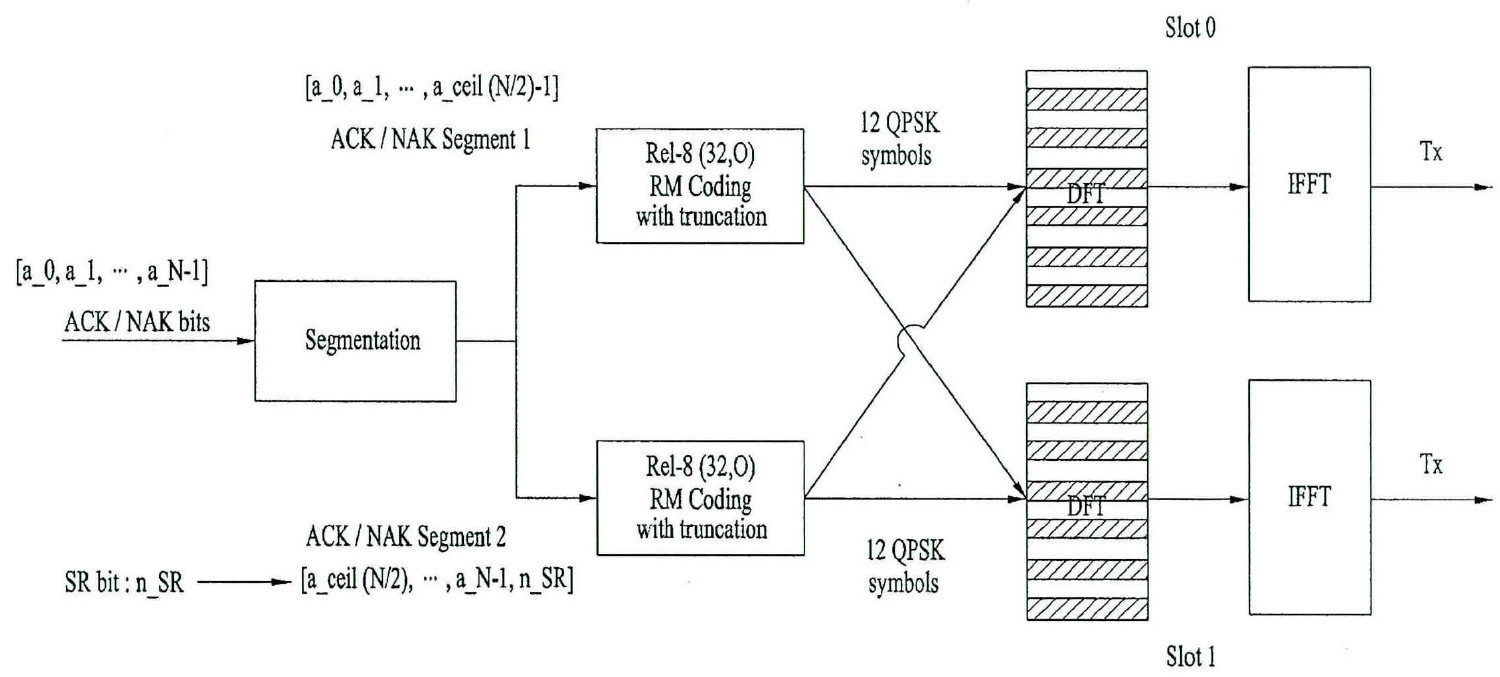
본 발명은 무선통신 시스템에 관한 것이다. 구체적으로, 무선 통신 시스템에서 단말이 ACK/NACK 및 SR(Scheduling Request)을 포함하는 제어정보를 전송하는 방법에 있어서, 복수개의 PDSCH(Physical Downlink Shared Channel)를 수신하는 단계 및 복수개의 PDSCH에 대응하는 복수개의 ACK/NACK과 SR을 PUCCH(Physical Uplink Control Channel) 포맷 3을 이용하여 전송하는 단계를 포함하고, 복수개의 ACK/NACK은 제 1 및 제 2 세그먼트로 분주되며, SR은 분주된 제 1 및 제 2 세그먼트 중 적어도 하나에 부가된 후에, 부가된 세그먼트의 복수개의 ACK/NACK과 조인트 코딩되는 제어정보 전송방법을 제공한다.
제공한다.The present invention relates to a wireless communication system. Specifically, a method for transmitting control information including an ACK / NACK and a scheduling request (SR) in a wireless communication system includes receiving a plurality of PDSCHs (Physical Downlink Shared Channel) Comprising the steps of: transmitting a plurality of ACK / NACK and SR using Physical Uplink Control Channel (PUCCH) format 3, wherein a plurality of ACK / NACKs are divided into first and second segments, And after being added to at least one of the second segments, jointly coded with a plurality of ACK / NACKs of the added segment.
to provide.
Description
본 발명은 무선 통신 시스템에 관한 것으로, 보다 상세하게는 제어 정보를 전송하는 방법 및 장치에 관한 것이다. 무선 통신 시스템은 캐리어 병합(Carrier Aggregation, CA)을 지원할 수 있다.The present invention relates to a wireless communication system, and more particularly, to a method and apparatus for transmitting control information. The wireless communication system may support Carrier Aggregation (CA).
무선 통신 시스템이 음성이나 데이터 등과 같은 다양한 종류의 통신 서비스를 제공하기 위해 광범위하게 전개되고 있다. 일반적으로 무선통신 시스템은 가용한 시스템 자원(대역폭, 전송 파워 등)을 공유하여 다중 사용자와의 통신을 지원할 수 있는 다중 접속(multiple access) 시스템이다. 다중 접속 시스템의 예들로는 CDMA(code division multiple access) 시스템, FDMA(frequency division multiple access) 시스템, TDMA(time division multiple access) 시스템, OFDMA(orthogonal frequency division multiple access) 시스템, SC-FDMA(single carrier frequency division multiple access) 시스템 등이 있다.Background of the Invention [0002] Wireless communication systems are widely deployed to provide various types of communication services such as voice and data. Generally, a wireless communication system is a multiple access system capable of supporting communication with multiple users by sharing available system resources (bandwidth, transmission power, etc.). Examples of multiple access systems include a code division multiple access (CDMA) system, a frequency division multiple access (FDMA) system, a time division multiple access (TDMA) system, an orthogonal frequency division multiple access (OFDMA) system, a single carrier frequency division multiple access) systems.
본 발명의 목적은 무선 통신 시스템에서 제어 정보를 효율적으로 전송하는 방법 및 이를 위한 장치를 제공하는데 있다. 본 발명의 다른 목적은 제어 정보를 효율적으로 전송하기 위한 채널 포맷, 신호 처리, 및 이를 위한 장치를 제공하는데 있다. 본 발명의 또 다른 목적은 제어 정보를 전송하기 위한 자원을 효율적으로 할당하는 방법 및 이를 위한 장치를 제공하는데 있다.It is an object of the present invention to provide a method and apparatus for efficiently transmitting control information in a wireless communication system. It is another object of the present invention to provide a channel format, signal processing, and apparatus for efficiently transmitting control information. It is still another object of the present invention to provide a method and apparatus for efficiently allocating resources for transmitting control information.
본 발명에서 이루고자 하는 기술적 과제들은 상기 기술적 과제로 제한되지 않으며, 언급하지 않은 또 다른 기술적 과제들은 아래의 기재로부터 본 발명이 속하는 기술분야에서 통상의 지식을 가진 자에게 명확하게 이해될 수 있을 것이다.The technical problems to be solved by the present invention are not limited to the technical problems and other technical problems which are not mentioned can be understood by those skilled in the art from the following description.
본 발명의 일 양상으로, 무선통신 시스템에서 단말이 ACK/NACK 및 SR(Scheduling Request)을 포함하는 제어정보를 전송하는 방법에 있어서, 복수개의 PDSCH(Physical Downlink Shared Channel)를 수신하는 단계 및 복수개의 PDSCH에 대응하는 복수개의 ACK/NACK과 SR을 PUCCH(Physical Uplink Control Channel) 포맷 3을 이용하여 전송하는 단계를 포함하고, 복수개의 ACK/NACK은 제 1 및 제 2 세그먼트로 분주되며, SR은 분주된 제 1 및 제 2 세그먼트 중 적어도 하나에 부가된 후에, 부가된 세그먼트의 복수개의 ACK/NACK과 조인트 코딩되는 제어정보 전송방법을 제공한다.According to an aspect of the present invention, there is provided a method for transmitting control information including an ACK / NACK and a scheduling request (SR) in a wireless communication system, the method comprising: receiving a plurality of physical downlink shared channels (PDSCHs) And transmitting a plurality of ACK / NACKs and SRs corresponding to the PDSCH using Physical Uplink Control Channel (PUCCH)
본 발명의 다른 양상으로, 무선통신 시스템에서 ACK/NACK 및 SR을 포함하는 제어정보를 전송하는 장치에 있어서, 무선 주파수(Radio Frequency, RF) 유닛 및 무선 주파수 유닛을 제어하여, 복수개의 PDSCH(Physical Downlink Shared Channel)를 수신하고, 복수개의 PDSCH에 대응하는 복수개의 ACK/NACK과 SR을 PUCCH(Physical Uplink Control Channel) 포맷 3을 이용하여 전송하는 프로세서를 포함하고, 복수개의 ACK/NACK은 제 1 및 제 2 세그먼트로 분주되며, SR은 분주된 제 1 및 제 2 세그먼트 중 적어도 하나에 부가된 후에, 부가된 세그먼트의 복수개의 ACK/NACK과 조인트 코딩되는 제어정보 전송장치를 제공한다.According to another aspect of the present invention, there is provided an apparatus for transmitting control information including ACK / NACK and SR in a wireless communication system, the apparatus comprising: a radio frequency (RF) unit and a radio frequency unit to control a plurality of PDSCH And a plurality of ACK / NACKs corresponding to a plurality of PDSCHs and transmitting the SRs using Physical Uplink Control Channel (PUCCH)
바람직하게, 복수개의 ACK/NACK의 수를 N이라 하면, 제 1 세그먼트는 N/2의 올림 값에 해당하는 ACK/NACK의 수가 분주되고, 제 2 세그먼트는 N에서 제 1 세그먼트로 분주된 ACK/NACK의 수를 제외한 ACK/NACK의 수가 분주된다.Preferably, when the number of ACK / NACKs is N, the first segment is divided by the number of ACK / NACKs corresponding to the N / 2 increase, and the second segment is divided into ACK / The number of ACKs / NACKs except for the number of NACKs is divided.
바람직하게, SR은 제 2 세그먼트에 부가된다.Preferably, SR is added to the second segment.
바람직하게, SR은 반복 코딩을 통하여 2×m(m은 임의의 정수)의 SR을 생성하고, 생성된 SR을 제 1 및 제 2 세그먼트에 동일하게 분주하여 부가된다.Preferably, the SR is generated by generating 2 x m (m is an arbitrary integer) SR through repetition coding, and the generated SR is equally divided into the first and second segments.
바람직하게, SR은 N이 홀수이면, 제 2 세그먼트에 부가되고, N이 짝수이면, 반복 코딩을 통하여 2×m(m은 임의의 정수)의 SR을 생성하고, 생성된 SR을 제 1 및 제 2 세그먼트에 동일하게 분주하여 부가된다.Preferably, SR is added to the second segment if N is an odd number, and if N is an even number, it generates 2 x m (m is any integer) SR through repetition coding, 2 segments are equally divided and added.
바람직하게, 복수개의 ACK/NACK의 수는 11을 초과한다.Preferably, the number of a plurality of ACK / NACKs exceeds 11.
바람직하게, 코딩은 Dual RM 코딩에 해당한다.Preferably, coding corresponds to Dual RM coding.
본 발명에 의하면, 무선 통신 시스템에서 제어 정보를 효율적으로 전송할 수 있다. 또한, 제어 정보를 효율적으로 전송하기 위한 채널 포맷, 신호 처리 방법을 제공할 수 있다. 또한, 제어 정보 전송을 위한 자원을 효율적으로 할당할 수 있다.According to the present invention, it is possible to efficiently transmit control information in a wireless communication system. Further, it is possible to provide a channel format and a signal processing method for efficiently transmitting control information. In addition, resources for control information transmission can be efficiently allocated.
본 발명에서 얻은 수 있는 효과는 이상에서 언급한 효과들로 제한되지 않으며, 언급하지 않은 또 다른 효과들은 아래의 기재로부터 본 발명이 속하는 기술분야에서 통상의 지식을 가진 자에게 명확하게 이해될 수 있을 것이다.The effects obtained by the present invention are not limited to the above-mentioned effects, and other effects not mentioned can be clearly understood by those skilled in the art from the following description will be.
본 발명에 관한 이해를 돕기 위해 상세한 설명의 일부로 포함되는, 첨부 도면은 본 발명에 대한 실시예를 제공하고, 상세한 설명과 함께 본 발명의 기술적 사상을 설명한다.
도 1은 무선 통신 시스템의 일례인 3GPP LTE 시스템에 이용되는 물리 채널들 및 이들을 이용한 일반적인 신호 전송 방법을 예시한다.
도 2는 무선 프레임의 구조를 예시한다.
도 3은 상향링크 신호 처리 과정을 예시한다.
도 4는 하향링크 신호 처리 과정을 예시한다.
도 5는 SC-FDMA 방식과 OFDMA 방식을 예시한다.
도 6은 단일 반송파 특성을 만족하기 위한 주파수 도메인 상의 신호 맵핑 방식을 예시한다.
도 7은 클러스터 SC-FDMA에서 DFT 프로세스 출력 샘플들이 단일 캐리어에 맵핑되는 신호 처리 과정을 예시한다.
도 8과 도 9는 클러스터 SC-FDMA에서 DFT 프로세스 출력 샘플들이 멀티캐리어(multi-carrier)에 맵핑되는 신호 처리 과정을 예시한다.
도 10은 세그먼트 SC-FDMA에서의 신호 처리 과정을 예시한다.
도 11은 상향링크 서브프레임의 구조를 예시한다.
도 12는 상향링크로 참조신호(Reference Signal, RS)를 전송하기 위한 신호 처리 과정을 예시한다.
도 13∼14는 PUSCH를 위한 DMRS(demodulation reference signal) 구조를 예시한다.
도 15∼16은 PUCCH 포맷 1a와 1b의 슬롯 레벨 구조를 예시한다.
도 17∼18은 PUCCH 포맷 2/2a/2b의 슬롯 레벨 구조를 예시한다.
도 19는 PUCCH 포맷 1a와 1b에 대한 ACK/NACK 채널화를 예시한다.
도 20은 동일한 PRB 내에서 PUCCH 포맷 1/1a/1b와 포맷 2/2a/2b의 혼합된 구조에 대한 채널화를 예시한다.
도 21은 PUCCH 전송을 위한 PRB 할당을 예시한다.
도 22는 기지국에서 하향링크 콤포넌트 캐리어를 관리하는 개념을 예시한다.
도 23은 단말에서 상향링크 콤포넌트 캐리어를 관리하는 개념을 예시한다.
도 24는 기지국에서 하나의 MAC이 멀티캐리어를 관리하는 개념을 예시한다.
도 25는 단말에서 하나의 MAC이 멀티캐리어를 관리하는 개념을 예시한다.
도 26은 기지국에서 하나의 MAC이 멀티캐리어를 관리하는 개념을 예시한다.
도 27은 단말에서 복수의 MAC이 멀티캐리어를 관리하는 개념을 예시한다.
도 28은 기지국에서 복수의 MAC이 멀티캐리어를 관리하는 개념을 예시한다.
도 29는 단말의 수신 관점에서, 하나 이상의 MAC이 멀티캐리어를 관리하는 개념을 예시한다.
도 30은 복수의 DL CC와 한 UL CC가 링크된 비대칭 캐리어 병합을 예시한다.
도 31∼36은 PUCCH 포맷 3의 구조 및 신호 처리 과정을 예시한다.
도 37∼38은 RS 다중화 용량이 증가된 PUCCH 포맷 3의 구조와 신호 처리 과정을 예시한다.
도 39는 본 발명이 적용되는 Dual RM 코딩을 설명하기 위한 블록도를 도시한 것이다.
도 40은 본 발명의 제 1 실시예에 따른 조인트 코딩 방법을 도시한 것이다.
도 41은 본 발명의 제 2 실시예에 따른 조인트 코딩 방법을 도시한 것이다.
도 42는 본 발명의 제 3 실시예에 따른 조인트 코딩 방법을 도시한 거이다
도 43은 본 발명의 제 4 실시예에 따른 조인트 코딩 방법을 도시한 것이다.
도 44 및 도 45는 본 발명의 제 6 실시예에 따른 조인트 코딩 방법을 도시한 것이다.
도 46은 본 발명에 적용될 수 있는 기지국 및 단말을 예시한다.BRIEF DESCRIPTION OF THE DRAWINGS The accompanying drawings, which are included to provide a further understanding of the invention and are incorporated in and constitute a part of the specification, illustrate embodiments of the invention and, together with the description, serve to explain the principles of the invention.
1 illustrates a physical channel used in a 3GPP LTE system, which is an example of a wireless communication system, and a general signal transmission method using the same.
2 illustrates the structure of a radio frame.
3 illustrates an uplink signal processing process.
4 illustrates a downlink signal processing process.
5 illustrates an SC-FDMA scheme and an OFDMA scheme.
6 illustrates a signal mapping scheme in the frequency domain to satisfy a single carrier characteristic.
Figure 7 illustrates a signal processing procedure in which the DFT process output samples in a cluster SC-FDMA are mapped to a single carrier.
8 and 9 illustrate a signal processing process in which DFT process output samples are mapped to multi-carriers in a cluster SC-FDMA.
10 illustrates a signal processing procedure in a segment SC-FDMA.
11 illustrates a structure of an uplink sub-frame.
12 illustrates a signal processing procedure for transmitting a reference signal (RS) in an uplink.
13-14 illustrate a demodulation reference signal (DMRS) structure for the PUSCH.
15 to 16 illustrate the slot level structure of the
17-18 illustrate the slot level structure of
FIG. 19 illustrates ACK / NACK channelization for
Figure 20 illustrates channelization for a mixed structure of
Figure 21 illustrates PRB allocation for PUCCH transmission.
22 illustrates a concept of managing a downlink component carrier at a base station.
23 illustrates a concept of managing an uplink component carrier in a terminal.
24 illustrates a concept that one MAC manages a multicarrier at a base station.
FIG. 25 illustrates a concept that one MAC manages a multicarrier in a terminal.
26 illustrates a concept that one MAC manages a multicarrier at a base station.
FIG. 27 illustrates a concept that a plurality of MACs manage a multi-carrier in a terminal.
28 illustrates a concept in which a plurality of MACs manage multicarriers at a base station.
FIG. 29 illustrates a concept that one or more MACs manage a multicarrier from the viewpoint of terminal reception.
30 illustrates asymmetric carrier merging in which a plurality of DL CCs and one UL CC are linked.
Figs. 31 to 36 illustrate the structure and signal processing of
37 to 38 illustrate the structure of a
FIG. 39 is a block diagram for explaining Dual RM coding to which the present invention is applied.
40 shows a joint coding method according to the first embodiment of the present invention.
41 shows a joint coding method according to the second embodiment of the present invention.
FIG. 42 shows a joint coding method according to the third embodiment of the present invention
43 shows a joint coding method according to the fourth embodiment of the present invention.
44 and 45 show a joint coding method according to a sixth embodiment of the present invention.
46 illustrates a base station and a terminal that can be applied to the present invention.
이하의 기술은 CDMA(code division multiple access), FDMA(frequency division multiple access), TDMA(time division multiple access), OFDMA(orthogonal frequency division multiple access), SC-FDMA(single carrier frequency division multiple access) 등과 같은 다양한 무선 접속 시스템에 사용될 수 있다. CDMA는 UTRA(Universal Terrestrial Radio Access)나 CDMA2000과 같은 무선 기술(radio technology)로 구현될 수 있다. TDMA는 GSM(Global System for Mobile communications)/GPRS(General Packet Radio Service)/EDGE(Enhanced Data Rates for GSM Evolution)와 같은 무선 기술로 구현될 수 있다. OFDMA는 IEEE 802.11 (Wi-Fi), IEEE 802.16 (WiMAX), IEEE 802-20, E-UTRA(Evolved UTRA) 등과 같은 무선 기술로 구현될 수 있다. UTRA는 UMTS(Universal Mobile Telecommunications System)의 일부이다. 3GPP(3rd Generation Partnership Project) LTE(long term evolution)은 E-UTRA를 사용하는 E-UMTS(Evolved UMTS)의 일부이고 LTE-A(Advanced)는 3GPP LTE의 진화된 버전이다. 설명을 명확하게 하기 위해, 3GPP LTE/LTE-A를 위주로 기술하지만 본 발명의 기술적 사상이 이에 제한되는 것은 아니다.The following description is to be understood as illustrative and non-limiting, such as code division multiple access (CDMA), frequency division multiple access (FDMA), time division multiple access (TDMA), orthogonal frequency division multiple access (OFDMA), single carrier frequency division multiple access And can be used in various wireless access systems. CDMA may be implemented in radio technology such as Universal Terrestrial Radio Access (UTRA) or CDMA2000. The TDMA may be implemented in a wireless technology such as Global System for Mobile communications (GSM) / General Packet Radio Service (GPRS) / Enhanced Data Rates for GSM Evolution (EDGE). OFDMA may be implemented in wireless technologies such as IEEE 802.11 (Wi-Fi), IEEE 802.16 (WiMAX), IEEE 802-20, and Evolved UTRA (E-UTRA). UTRA is part of the Universal Mobile Telecommunications System (UMTS). 3rd Generation Partnership Project (3GPP) Long term evolution (LTE) is part of E-UMTS (Evolved UMTS) using E-UTRA and LTE-A (Advanced) is an evolved version of 3GPP LTE. For clarity of description, 3GPP LTE / LTE-A is mainly described, but the technical idea of the present invention is not limited thereto.
무선 통신 시스템에서 단말은 기지국으로부터 하향링크(Downlink, DL)를 통해 정보를 수신하고, 단말은 기지국으로 상향링크(Uplink, UL)를 통해 정보를 전송한다. 기지국과 단말이 송수신하는 정보는 데이터 및 다양한 제어 정보를 포함하고, 이들이 송수신 하는 정보의 종류/용도에 따라 다양한 물리 채널이 존재한다.In a wireless communication system, a terminal receives information from a base station through a downlink (DL), and the terminal transmits information through an uplink (UL) to a base station. The information transmitted and received by the base station and the terminal includes data and various control information, and various physical channels exist depending on the type / use of the information transmitted / received.
도 1은 3GPP LTE 시스템에 이용되는 물리 채널들 및 이들을 이용한 일반적인 신호 전송 방법을 설명하기 위한 도면이다.1 is a view for explaining a physical channel used in a 3GPP LTE system and a general signal transmission method using the same.
전원이 꺼진 상태에서 다시 전원이 켜지거나, 새로이 셀에 진입한 단말은 단계 S101에서 기지국과 동기를 맞추는 등의 초기 셀 탐색(Initial cell search) 작업을 수행한다. 이를 위해 단말은 기지국으로부터 주동기 채널(Primary Synchronization Channel, P-SCH) 및 부동기 채널(Secondary Synchronization Channel, S-SCH)을 수신하여 기지국과 동기를 맞추고, 셀 ID 등의 정보를 획득한다. 그 후, 단말은 기지국으로부터 물리방송채널(Physical Broadcast Channel)를 수신하여 셀 내 방송 정보를 획득할 수 있다. 한편, 단말은 초기 셀 탐색 단계에서 하향링크 참조 신호(Downlink Reference Signal, DL RS)를 수신하여 하향링크 채널 상태를 확인할 수 있다.The terminal that is powered on again or the cell that has entered a new cell performs an initial cell search operation such as synchronizing with the base station in step S101. To this end, a mobile station receives a primary synchronization channel (P-SCH) and a secondary synchronization channel (S-SCH) from a base station, synchronizes with the base station, and acquires information such as a cell ID. Then, the terminal can receive the physical broadcast channel from the base station and acquire the in-cell broadcast information. Meanwhile, the UE can receive the downlink reference signal (DL RS) in the initial cell search step to check the downlink channel state.
초기 셀 탐색을 마친 단말은 단계 S102에서 물리 하향링크제어채널(Physical Downlink Control Channel, PDCCH) 및 물리하향링크제어채널 정보에 따른 물리하향링크공유 채널(Physical Downlink Control Channel, PDSCH)을 수신하여 좀더 구체적인 시스템 정보를 획득할 수 있다.Upon completion of the initial cell search, the UE receives a Physical Downlink Control Channel (PDCCH) and a physical downlink control channel (PDSCH) according to physical downlink control channel information in step S102, System information can be obtained.
이후, 단말은 기지국에 접속을 완료하기 위해 이후 단계 S103 내지 단계 S106과 같은 임의 접속 과정(Random Access Procedure)을 수행할 수 있다. 이를 위해 단말은 물리임의접속채널(Physical Random Access Channel, PRACH)을 통해 프리앰블(preamble)을 전송하고(S103), 물리하향링크제어채널 및 이에 대응하는 물리하향링크공유 채널을 통해 프리앰블에 대한 응답 메시지를 수신할 수 있다(S104). 경쟁 기반 임의 접속의 경우 추가적인 물리임의접속채널의 전송(S105) 및 물리하향링크제어채널 및 이에 대응하는 물리하향링크공유 채널 수신(S106)과 같은 충돌해결절차(Contention Resolution Procedure)를 수행할 수 있다.Thereafter, the terminal can perform a random access procedure such as steps S103 to S106 in order to complete the connection to the base station. To this end, the UE transmits a preamble through a Physical Random Access Channel (PRACH) (S103), and transmits a response message for a preamble through the physical downlink control channel and the corresponding physical downlink shared channel (S104). In the case of a contention-based random access, a contention resolution procedure such as transmission of an additional physical random access channel (S105) and physical downlink control channel and corresponding physical downlink shared channel reception (S106) can be performed .
상술한 바와 같은 절차를 수행한 단말은 이후 일반적인 상/하향링크 신호 전송 절차로서 물리하향링크제어채널/물리하향링크공유채널 수신(S107) 및 물리상향링크공유채널(Physical Uplink Shared Channel, PUSCH)/물리상향링크제어채널(Physical Uplink Control Channel, PUCCH) 전송(S108)을 수행할 수 있다. 단말이 기지국으로 전송하는 제어 정보를 통칭하여 상향링크 제어 정보(Uplink Control Information, UCI)라고 지칭한다. UCI는 HARQ ACK/NACK(Hybrid Automatic Repeat and reQuest Acknowledgement/Negative-ACK), SR(Scheduling Request), CQI(Channel Quality Indicator), PMI(Precoding Matrix Indicator), RI(Rank Indication) 등을 포함한다. 본 명세서에서, HARQ ACK/NACK은 간단히 HARQ-ACK 혹은 ACK/NACK(A/N)으로 지칭된다. HARQ-ACK은 포지티브 ACK(간단히, ACK), 네거티브 ACK(NACK), DTX 및 NACK/DTX 중 적어도 하나를 포함한다. UCI는 일반적으로 PUCCH를 통해 전송되지만, 제어 정보와 트래픽 데이터가 동시에 전송되어야 할 경우 PUSCH를 통해 전송될 수 있다. 또한, 네트워크의 요청/지시에 의해 PUSCH를 통해 UCI를 비주기적으로 전송할 수 있다.The UE having performed the above procedure can then receive physical downlink control channel / physical downlink shared channel reception (S107) and physical uplink shared channel (PUSCH) / physical downlink shared channel A Physical Uplink Control Channel (PUCCH) transmission (S108) may be performed. The control information transmitted from the UE to the Node B is collectively referred to as Uplink Control Information (UCI). The UCI includes HARQ ACK / NACK, a Scheduling Request (SR), a Channel Quality Indicator (CQI), a Precoding Matrix Indicator (PMI), and Rank Indication (RI). In this specification, HARQ ACK / NACK is simply referred to as HARQ-ACK or ACK / NACK (A / N). The HARQ-ACK includes at least one of positive ACK (simply ACK), negative ACK (NACK), DTX and NACK / DTX. The UCI is generally transmitted through the PUCCH, but may be transmitted via the PUSCH when the control information and the traffic data are to be simultaneously transmitted. In addition, UCI can be transmitted non-periodically through the PUSCH according to the request / instruction of the network.
도 2는 무선 프레임의 구조를 예시한다. 셀룰라 OFDM 무선 패킷 통신 시스템에서, 상향링크/하향링크 데이터 패킷 전송은 서브프레임(subframe) 단위로 이루어지며, 한 서브프레임은 다수의 OFDM 심볼을 포함하는 일정 시간 구간으로 정의된다. 3GPP LTE 표준에서는 FDD(Frequency Division Duplex)에 적용 가능한 타입 1 무선 프레임(radio frame) 구조와 TDD(Time Division Duplex)에 적용 가능한 타입 2의 무선 프레임 구조를 지원한다.2 illustrates the structure of a radio frame. In a cellular OFDM wireless packet communication system, uplink / downlink data packet transmission is performed on a subframe basis, and one subframe is defined as a predetermined time interval including a plurality of OFDM symbols. The 3GPP LTE standard supports a
도 2(a)는 타입 1 무선 프레임의 구조를 예시한다. 하향링크 무선 프레임(radio frame)은 10개의 서브프레임(subframe)으로 구성되고, 하나의 서브프레임은 시간 영역(time domain)에서 2개의 슬롯(slot)으로 구성된다. 하나의 서브프레임이 전송되는 데 걸리는 시간을 TTI(transmission time interval)라 한다. 예를 들어 하나의 서브프레임의 길이는 1ms이고, 하나의 슬롯의 길이는 0.5ms 일 수 있다. 하나의 슬롯은 시간 영역에서 복수의 OFDM 심볼을 포함하고, 주파수 영역에서 다수의 자원블록(Resource Block; RB)을 포함한다. 3GPP LTE 시스템에서는 하향링크에서 OFDMA 를 사용하므로, OFDM 심볼이 하나의 심볼 구간을 나타낸다. OFDM 심볼은 또한 SC-FDMA 심볼 또는 심볼 구간으로 칭하여질 수도 있다. 자원 할당 단위로서의 자원 블록(RB)은 하나의 슬롯에서 복수개의 연속적인 부반송파(subcarrier)를 포함할 수 있다.2 (a) illustrates the structure of a
하나의 슬롯에 포함되는 OFDM 심볼의 수는 CP(Cyclic Prefix)의 구성(configuration)에 따라 달라질 수 있다. CP에는 확장된 CP(extended CP)와 표준 CP(normal CP)가 있다. 예를 들어, OFDM 심볼이 표준 CP에 의해 구성된 경우, 하나의 슬롯에 포함되는 OFDM 심볼의 수는 7개일 수 있다. OFDM 심볼이 확장된 CP에 의해 구성된 경우, 한 OFDM 심볼의 길이가 늘어나므로, 한 슬롯에 포함되는 OFDM 심볼의 수는 표준 CP인 경우보다 적다. 확장된 CP의 경우에, 예를 들어, 하나의 슬롯에 포함되는 OFDM 심볼의 수는 6개일 수 있다. 단말이 빠른 속도로 이동하는 등의 경우와 같이 채널상태가 불안정한 경우, 심볼간 간섭을 더욱 줄이기 위해 확장된 CP가 사용될 수 있다.The number of OFDM symbols included in one slot may vary according to the configuration of a CP (Cyclic Prefix). CP has an extended CP and a normal CP. For example, when an OFDM symbol is configured by a standard CP, the number of OFDM symbols included in one slot may be seven. When the OFDM symbol is configured by an extended CP, the length of one OFDM symbol is increased, so that the number of OFDM symbols included in one slot is smaller than that in the standard CP. In the case of the extended CP, for example, the number of OFDM symbols included in one slot may be six. If the channel condition is unstable, such as when the UE moves at a high speed, an extended CP may be used to further reduce inter-symbol interference.
표준 CP가 사용되는 경우 하나의 슬롯은 7개의 OFDM 심볼을 포함하므로, 하나의 서브프레임은 14개의 OFDM 심볼을 포함한다. 이때, 각 서브프레임의 처음 최대 3 개의 OFDM 심볼은 PDCCH(physical downlink control channel)에 할당되고, 나머지 OFDM 심볼은 PDSCH(physical downlink shared channel)에 할당될 수 있다.One slot includes 7 OFDM symbols when a standard CP is used, so one subframe includes 14 OFDM symbols. At this time, the first three OFDM symbols at the beginning of each subframe may be allocated to a physical downlink control channel (PDCCH), and the remaining OFDM symbols may be allocated to a physical downlink shared channel (PDSCH).
도 2(b)는 타입 2 무선 프레임의 구조를 예시한다. 타입 2 무선 프레임은 2개의 하프 프레임(half frame)으로 구성되며, 각 하프 프레임은 5개의 서브프레임과 DwPTS(Downlink Pilot Time Slot), 보호구간(Guard Period, GP), UpPTS(Uplink Pilot Time Slot)로 구성되며, 이 중 1개의 서브프레임은 2개의 슬롯으로 구성된다. DwPTS는 단말에서의 초기 셀 탐색, 동기화 또는 채널 추정에 사용된다. UpPTS는 기지국에서의 채널 추정과 단말의 상향링크 전송 동기를 맞추는데 사용된다. 보호구간은 상향링크와 하향링크 사이에 하향링크 신호의 다중경로 지연으로 인해 상향링크에서 생기는 간섭을 제거하기 위한 구간이다.2 (b) illustrates the structure of a
무선 프레임의 구조는 예시에 불과하고, 무선 프레임에 포함되는 서브프레임의 수 또는 서브프레임에 포함되는 슬롯의 수, 슬롯에 포함되는 심볼의 수는 다양하게 변경될 수 있다.The structure of the radio frame is merely an example, and the number of subframes included in a radio frame, the number of slots included in a subframe, and the number of symbols included in a slot can be variously changed.
도 3은 단말이 상향링크 신호를 전송하기 위한 신호 처리 과정을 설명하기 위한 도면이다.3 is a diagram for explaining a signal processing procedure for a UE to transmit an uplink signal.
상향링크 신호를 전송하기 위해 단말의 스크램블링(scrambling) 모듈(210)은 단말 특정 스크램블 신호를 이용하여 전송 신호를 스크램블 할 수 있다. 스크램블 된 신호는 변조 맵퍼(220)에 입력되어 전송 신호의 종류 및/또는 채널 상태에 따라 BPSK(Binary Phase Shift Keying), QPSK(Quadrature Phase Shift Keying) 또는 16QAM/64QAM(Quadrature Amplitude Modulation) 방식을 이용하여 복소 심볼(complex symbol)로 변조된다. 변조된 복소 심볼은 변환 프리코더(230)에 의해 처리된 후, 자원 요소 맵퍼(240)에 입력되며, 자원 요소 맵퍼(240)는 복소 심볼을 시간-주파수 자원 요소에 맵핑할 수 있다. 이와 같이 처리된 신호는 SC-FDMA 신호 생성기(250)를 거쳐 안테나를 통해 기지국으로 전송될 수 있다.In order to transmit the uplink signal, the scrambling module 210 of the UE may scramble the transmission signal using the UE-specific scrambling signal. The scrambled signal is input to the modulation mapper 220, and is used to perform BPSK (Binary Phase Shift Keying), QPSK (Quadrature Phase Shift Keying), or 16QAM / 64QAM (Quadrature Amplitude Modulation) according to the type and / And is then modulated into a complex symbol. After the modulated complex symbols are processed by the transform precoder 230, they are input to the resource element mapper 240 and the resource element mapper 240 can map the complex symbols to the time-frequency resource elements. The signal thus processed can be transmitted to the base station via the antenna via the SC-FDMA signal generator 250. [
도 4는 기지국이 하향링크 신호를 전송하기 위한 신호 처리 과정을 설명하기 위한 도면이다.4 is a diagram for explaining a signal processing procedure for a base station to transmit a downlink signal.
3GPP LTE 시스템에서 기지국은 하향링크로 하나 이상의 코드워드(codeword)를 전송할 수 있다. 코드워드는 각각 도 3의 상향링크에서와 마찬가지로 스크램블 모듈(301) 및 변조 맵퍼(302)를 통해 복소 심볼로 처리될 수 있다, 그 후, 복소 심볼은 레이어 맵퍼(303)에 의해 복수의 레이어(Layer)에 맵핑되며, 각 레이어는 프리코딩 모듈(304)에 의해 프리코딩 행렬과 곱해져 각 전송 안테나에 할당될 수 있다. 이와 같이 처리된 각 안테나 별 전송 신호는 각각 자원 요소 맵퍼(305)에 의해 시간-주파수 자원 요소에 맵핑되며, 이후 OFDM(Orthogonal Frequency Division Multiple Access) 신호 생성기(306)를 거쳐 각 안테나를 통해 전송될 수 있다.In a 3GPP LTE system, a base station may transmit one or more codewords in the downlink. The codeword may be processed into a complex symbol through the
무선 통신 시스템에서 단말이 상향링크로 신호를 전송하는 경우에는 기지국이 하향링크로 신호를 전송하는 경우에 비해 PAPR(Peak-to-Average Ratio)이 문제된다. 따라서, 도 3 및 도 4와 관련하여 상술한 바와 같이 상향링크 신호 전송은 하향링크 신호 전송에 이용되는 OFDMA 방식과 달리 SC-FDMA(Single Carrier-Frequency Division Multiple Access) 방식이 이용되고 있다.In a wireless communication system, when a mobile station transmits a signal in an uplink, a peak-to-average ratio (PAPR) is more problematic than a case where a base station transmits a downlink signal. Therefore, as described above with reference to FIGS. 3 and 4, the uplink signal transmission uses an SC-FDMA (Single Carrier-Frequency Division Multiple Access) scheme unlike the OFDMA scheme used for downlink signal transmission.
도 5는 SC-FDMA 방식과 OFDMA 방식을 설명하기 위한 도면이다. 3GPP 시스템은 하향링크에서 OFDMA를 채용하고 상향링크에서 SC-FDMA를 채용한다5 is a diagram for explaining an SC-FDMA scheme and an OFDMA scheme. The 3GPP system employs OFDMA in the downlink and SC-FDMA in the uplink
도 5를 참조하면, 상향링크 신호 전송을 위한 단말 및 하향링크 신호 전송을 위한 기지국 모두 직렬-병렬 변환기(Serial-to-Parallel Converter)(401), 부반송파 맵퍼(403), M-포인트 IDFT 모듈(404) 및 CP(Cyclic Prefix) 추가 모듈(406)을 포함하는 점에 있어서는 동일하다. 다만, SC-FDMA 방식으로 신호를 전송하기 위한 단말은 N-포인트 DFT 모듈(402)을 추가로 포함한다. N-포인트 DFT 모듈(402)은 M-포인트 IDFT 모듈(404)의 IDFT 처리 영향을 일정 부분 상쇄함으로써 전송 신호가 단일 반송파 특성(single carrier property)을 가지도록 한다.Referring to FIG. 5, both a terminal for uplink signal transmission and a base station for downlink signal transmission include a serial-to-
도 6은 주파수 도메인에서 단일 반송파 특성을 만족하기 위한 주파수 도메인상의 신호 맵핑 방식을 설명하는 도면이다. 도 6(a)는 로컬형 맵핑(localized mapping) 방식을 나타내며, 도 6(b)는 분산형 맵핑(distributed mapping) 방식을 나타낸다.6 is a view for explaining a signal mapping method in the frequency domain for satisfying a single carrier characteristic in the frequency domain. FIG. 6A shows a localized mapping method, and FIG. 6B shows a distributed mapping method.
SC-FDMA의 수정된 형태인 클러스터(clustered) SC-FDMA에 대해 설명한다. 클러스터(clustered) SC-FDMA는 부반송파 맵핑(mapping) 과정에서 DFT 프로세스 출력 샘플들을 부 그룹(sub-group)으로 나뉘고, 이들을 주파수 도메인(혹은 부반송파 도메인)에 불연속적으로 맵핑한다.A modified version of SC-FDMA, clustered SC-FDMA, is described. In a clustered SC-FDMA, the DFT process output samples are divided into sub-groups in a subcarrier mapping process and are discontinuously mapped to a frequency domain (or a subcarrier domain).
도 7은 클러스터 SC-FDMA에서 DFT 프로세스 출력 샘플들이 단일 캐리어에 맵핑되는 신호 처리 과정을 도시하는 도면이다. 도 8과 도 9는 클러스터 SC-FDMA에서 DFT 프로세스 출력 샘플들이 멀티캐리어(multi-carrier)에 맵핑되는 신호 처리 과정을 도시하는 도면이다. 도 7은 인트라 캐리어(intra-carrier) 클러스터 SC-FDMA를 적용하는 예이고, 도 8과 도 9는 인터 캐리어(inter-carrier) 클러스터 SC-FDMA를 적용하는 예에 해당한다. 도 8은 주파수 도메인에서 연속적(contiguous)으로 콤포넌트 캐리어(component carrier)가 할당된 상황에서 인접한 콤포넌트 캐리어간의 부반송파 간격(spacing)이 정렬된 경우 단일 IFFT 블록을 통해 신호를 생성하는 경우를 나타낸다. 도 9는 주파수 도메인에서 비연속적(non-contiguous)으로 콤포넌트 캐리어가 할당된 상황에서 복수의 IFFT 블록을 통해 신호를 생성하는 경우를 나타낸다.7 is a diagram illustrating a signal processing process in which DFT process output samples in a cluster SC-FDMA are mapped to a single carrier. 8 and 9 are diagrams illustrating a signal processing process in which DFT process output samples in a cluster SC-FDMA are mapped to multi-carriers. FIG. 7 shows an example of applying an intra-carrier cluster SC-FDMA, and FIGS. 8 and 9 correspond to an example of applying an inter-carrier cluster SC-FDMA. 8 shows a case where a signal is generated through a single IFFT block when subcarrier spacing between adjacent component carriers is aligned in a situation where a component carrier is allocated contiguously in the frequency domain. FIG. 9 shows a case where a signal is generated through a plurality of IFFT blocks in a situation where a component carrier is allocated non-contiguously in the frequency domain.
도 10은 세그먼트(segmented) SC-FDMA의 신호 처리 과정을 도시하는 도면이다.10 is a diagram showing a signal processing process of segmented SC-FDMA.
세그먼트 SC-FDMA는 임의 개수의 DFT와 같은 개수의 IFFT가 적용되면서 DFT와 IFFT간의 관계 구성이 일대일 관계를 가짐에 따라 단순히 기존 SC-FDMA의 DFT 확산과 IFFT의 주파수 부반송파 맵핑 구성을 확장한 것으로 NxSC-FDMA 또는 NxDFT-s-OFDMA라고 표현되기도 한다. 본 명세서는 이들을 포괄하여 세그먼트 SC-FDMA라고 명명한다. 도 10을 참조하면, 세그먼트 SC-FDMA는 단일 반송파 특성 조건을 완화하기 위하여 전체 시간 도메인 변조 심볼들을 N(N은 1보다 큰 정수)개의 그룹으로 묶어 그룹 단위로 DFT 프로세스를 수행한다.Segment SC-FDMA is an extension of DFT spreading of existing SC-FDMA and frequency subcarrier mapping of IFFT as the number of IFFTs is the same as that of any number of DFTs, as the relationship structure between DFT and IFFT has a one- -FDMA or NxDFT-s-OFDMA. The present specification encompasses them as a segment SC-FDMA. Referring to FIG. 10, the segment SC-FDMA groups all the time-domain modulation symbols into N groups (N is an integer larger than 1) to perform a DFT process on a group basis in order to relax a single carrier characteristic condition.
도 11은 상향링크 서브프레임의 구조를 예시한다.11 illustrates a structure of an uplink sub-frame.
도 11을 참조하면, 상향링크 서브프레임은 복수(예, 2개)의 슬롯을 포함한다. 슬롯은 CP(Cyclic Prefix) 길이에 따라 서로 다른 수의 SC-FDMA 심볼을 포함할 수 있다. 일 예로, 일반(normal) CP의 경우 슬롯은 7개의 SC-FDMA 심볼을 포함할 수 있다. 상향링크 서브프레임은 데이터 영역과 제어 영역으로 구분된다. 데이터 영역은 PUSCH를 포함하고 음성 등의 데이터 신호 전송하는데 사용된다. 제어 영역은 PUCCH를 포함하고 제어 정보를 전송하는데 사용된다. PUCCH는 주파수 축에서 데이터 영역의 양끝부분에 위치한 RB 쌍(RB pair)(예, m=0,1,2,3))(예, 주파수 반사(frequency mirrored)된 위치의 RB 쌍)을 포함하며 슬롯을 경계로 호핑한다. 상향링크 제어 정보(즉, UCI)는 HARQ ACK/NACK, CQI(Channel Quality Indicator), PMI(Precoding Matrix Indicator), RI(Rank Indication) 등을 포함한다.Referring to FIG. 11, the uplink subframe includes a plurality of (e.g., two) slots. The slot may include a different number of SC-FDMA symbols according to a CP (Cyclic Prefix) length. For example, in the case of a normal CP, a slot may include 7 SC-FDMA symbols. The uplink subframe is divided into a data area and a control area. The data area includes a PUSCH and is used to transmit data signals such as voice. The control domain includes the PUCCH and is used to transmit control information. The PUCCH includes an RB pair (e.g., m = 0, 1, 2, 3) (e.g., a pair of RBs in a frequency mirrored position) located at both ends of a data region on the frequency axis Hops the slot to the boundary. The uplink control information (i.e., UCI) includes HARQ ACK / NACK, Channel Quality Indicator (CQI), Precoding Matrix Indicator (PMI), and Rank Indication (RI).
도 12는 상향링크로 참조신호를 전송하기 위한 신호 처리 과정을 설명하기 위한 도면이다. 데이터는 DFT 프리코더(precoder)를 통해 주파수 영역 신호로 변환된 뒤, 주파수 맵핑 후 IFFT를 통해 전송되는 반면, RS는 DFT 프리코더를 통하는 과정이 생략된다. 구체적으로, 주파수 영역에서 RS 시퀀스가 바로 생성(S11)된 후에, 로컬화 맵핑(S12), IFFT(S13) 과정 및 순환 전치(Cyclic Prefix, CP) 부착 과정(S14)을 순차적으로 거쳐 RS가 전송된다.12 is a diagram for explaining a signal processing procedure for transmitting a reference signal in an uplink. The data is converted into a frequency domain signal through a DFT precoder and then transmitted through an IFFT after frequency mapping, whereas the process of passing through a DFT precoder is omitted from the RS. Specifically, after the RS sequence is directly generated (S11) in the frequency domain, the RS is sequentially transmitted through the localization mapping (S12), the IFFT (S13) process and the cyclic prefix (CP) do.
RS 시퀀스 ![]()
![]()
![]()
![]()
여기에서, ![]()
![]()
![]()
![]()
![]()
![]()
![]()
![]()
기본 시퀀스인 ![]()
![]()
![]()
![]()
![]()
![]()
![]()
![]()
![]()
![]()
![]()
![]()
![]()
![]()
![]()
![]()
![]()
![]()
![]()
![]()
![]()
![]()
![]()
![]()
![]()
![]()
![]()
![]()
![]()
![]()
![]()
![]()
![]()
![]()
여기에서, q번째 루트 자도프-츄(Zadoff-Chu) 시퀀스는 다음의 수학식 3에 의해 정의될 수 있다.Here, the q-th root Zadoff-Chu sequence can be defined by the following equation (3).
![]()
![]()
여기에서, q는 다음의 수학식 4을 만족한다.Here, q satisfies the following expression (4).

여기에서, 자도프-츄 시퀀스의 길이 ![]()
![]()
![]()
![]()
![]()
![]()
![]()
![]()
![]()
![]()
![]()
![]()
여기에서, ![]()
![]()
![]()
![]()
![]()
![]()


한편, RS 호핑(hopping)에 대해 설명하면 다음과 같다.RS hopping will be described as follows.
그룹 호핑 패턴 ![]()
![]()
![]()
![]()
![]()
![]()
![]()
![]()
![]()
![]()
여기에서, mod는 모듈로(modulo)연산을 나타낸다.Here, mod represents a modulo operation.
17개의 서로 다른 호핑 패턴과 30개의 서로 다른 시퀀스 시프트 패턴이 존재한다. 상위 계층에 의해 제공된 그룹 호핑을 활성화시키는 파라미터에 의해 시퀀스 그룹 호핑이 가능(enabled)하거나 불가능할(disabled) 수 있다.There are 17 different hopping patterns and 30 different sequence shift patterns. Sequence group hopping may be enabled or disabled by a parameter that activates the group hopping provided by the upper layer.
PUCCH와 PUSCH는 동일한 호핑 패턴을 가지지만 서로 다른 시퀀스 시프트 패턴을 가질 수 있다.PUCCH and PUSCH have the same hopping pattern but can have different sequence shift patterns.
그룹 호핑 패턴 ![]()
![]()

여기에서 ![]()

![]()
시퀀스 시프트 패턴 ![]()
![]()
PUCCH에 대해서, 시퀀스 시프트 패턴 ![]()
![]()
![]()
![]()
![]()
![]()
![]()
![]()
![]()
![]()
이하, 시퀀스 호핑에 대해 설명한다.Sequence hopping will be described below.
시퀀스 호핑은 길이가 ![]()
![]()
길이가 ![]()
![]()
![]()
![]()
![]()
![]()
길이가 ![]()
![]()
![]()
![]()
![]()
![]()
![]()
![]()
여기에서, ![]()
![]()
![]()
![]()
PUSCH에 대한 기준 신호는 다음과 같이 결정된다.The reference signal for PUSCH is determined as follows.
PUSCH에 대한 기준 신호 시퀀스 ![]()
![]()
![]()
![]()
![]()
![]()
![]()
![]()
한 슬롯에서 순환 시프트는 ![]()
![]()
![]()
![]()
![]()
![]()
![]()
![]()
![]()
![]()
![]()
![]()
![]()
![]()
![]()
![]()

![]()
![]()
표 3은 DCI(Downlink Control Information) 포맷 0에서 순환 시프트 필드와 ![]()
![]()

PUSCH에서 상향링크 RS를 위한 물리적 맵핑 방법은 다음과 같다.A physical mapping method for the uplink RS in the PUSCH is as follows.
시퀀스는 진폭 스케일링 요소(amplitude scaling factor) ![]()
![]()
![]()
![]()
![]()
![]()
![]()
![]()
![]()
![]()
![]()
![]()
정리하면, 길이가 ![]()
![]()
![]()
![]()
도 13은 표준 순환 전치(normal CP)의 경우에 PUSCH를 위한 DMRS(demodulation reference signal) 구조를 도시한 도면이고, 도 14는 확장 순환 전치(extended CP)의 경우에 PUSCH를 위한 DMRS 구조를 도시한 도면이다. 도 13에서는 4번째와 11번째 SC-FDMA 심볼을 통해 DMRS가 전송되며, 도 14에서는 3번째와 9번째 SC-FDMA 심볼을 통해 DMRS가 전송된다.FIG. 13 is a diagram illustrating a DMRS (demodulation reference signal) structure for a PUSCH in the case of a standard cyclic prefix (CP), and FIG. 14 illustrates a DMRS structure for a PUSCH in the case of an extended CP FIG. In FIG. 13, the DMRS is transmitted through the fourth and eleventh SC-FDMA symbols. In FIG. 14, the DMRS is transmitted through the third and ninth SC-FDMA symbols.
도 15∼18은 PUCCH 포맷의 슬롯 레벨 구조를 예시한다. PUCCH는 제어 정보를 전송하기 위하여 다음의 형식을 포함한다.15 to 18 illustrate a slot level structure of the PUCCH format. The PUCCH includes the following format for transmitting the control information.
(1) 포맷(Format) 1: 온-오프 키잉(On-Off keying)(OOK) 변조, 스케줄링 요청(Scheduling Request, SR)에 사용(1) Format 1: Used for on-off keying (OOK) modulation, scheduling request (SR)
(2) 포맷 1a와 포맷 1b: ACK/NACK(Acknowledgment/Negative Acknowledgment) 전송에 사용(2)
1) 포맷 1a: 1개의 코드워드에 대한 BPSK ACK/NACK1)
2) 포맷 1b: 2개의 코드워드에 대한 QPSK ACK/NACK[2)
(3) 포맷 2: QPSK 변조, CQI 전송에 사용(3) Format 2: Used for QPSK modulation and CQI transmission
(4) 포맷 2a와 포맷 2b: CQI와 ACK/NACK 동시 전송에 사용(4)
표 4는 PUCCH 포맷에 따른 변조 방식과 서브프레임 당 비트 수를 나타낸다. 표 5는 PUCCH 포맷에 따른 슬롯 당 RS의 개수를 나타낸다. 표 6은 PUCCH 포맷에 따른 RS의 SC-FDMA 심볼 위치를 나타낸 표이다. 표 4에서 PUCCH 포맷 2a와 2b는 표준 순환 전치의 경우에 해당한다.Table 4 shows the modulation scheme according to the PUCCH format and the number of bits per subframe. Table 5 shows the number of RSs per slot according to the PUCCH format. Table 6 shows SC-FDMA symbol positions of RS according to the PUCCH format. In Table 4, PUCCH formats 2a and 2b correspond to the case of standard cyclic transposition.


도 15는 표준 순환 전치인 경우의 PUCCH 포맷 1a와 1b를 나타낸다. 도 16은 확장 순환 전치인 경우의 PUCCH 포맷 1a와 1b를 나타낸다. PUCCH 포맷 1a와 1b는 동일한 내용의 제어 정보가 서브프레임 내에서 슬롯 단위로 반복된다. 각 단말에서 ACK/NACK 신호는 CG-CAZAC(Computer-Generated Constant Amplitude Zero Auto Correlation) 시퀀스의 서로 다른 순환 쉬프트(cyclic shift, CS)(주파수 도메인 코드)와 직교 커버 코드(orthogonal cover or orthogonal cover code, OC or OCC)(시간 도메인 확산 코드)로 구성된 서로 다른 자원을 통해 전송된다. OC는 예를 들어 왈쉬(Walsh)/DFT 직교 코드를 포함한다. CS의 개수가 6개이고 OC의 개수가 3개이면, 단일 안테나를 기준으로 총 18개의 단말이 동일한 PRB(Physical Resource Block) 안에서 다중화 될 수 있다. 직교 시퀀스 w0,w1,w2,w3는 (FFT 변조 후에) 임의의 시간 도메인에서 또는 (FFT 변조 전에) 임의의 주파수 도메인에서 적용될 수 있다.15 shows the PUCCH formats 1a and 1b in the case of standard cyclic permutation. 16 shows PUCCH formats 1a and 1b in the case of extended cyclic permutation. In the PUCCH formats 1a and 1b, control information having the same contents is repeated in a slot unit in a subframe. In each terminal, the ACK / NACK signal includes a different cyclic shift (CS) (frequency domain code) and orthogonal cover or orthogonal cover code (CG-CAZAC) OC or OCC) (time domain spreading code). The OC includes, for example, a Walsh / DFT orthogonal code. If the number of CSs is 6 and the number of OCs is 3, a total of 18 terminals based on a single antenna can be multiplexed in the same physical resource block (PRB). The orthogonal sequences w0, w1, w2, w3 may be applied in any time domain (after FFT modulation) or in any frequency domain (before FFT modulation).
SR과 지속적 스케줄링(persistent scheduling)을 위해, CS, OC 및 PRB(Physical Resource Block)로 구성된 ACK/NACK 자원은 RRC(Radio Resource Control)를 통해 단말에게 주어질 수 있다. 동적 ACK/NACK과 비지속적 스케줄링(non-persistent scheduling)을 위해, ACK/NACK 자원은 PDSCH에 대응하는 PDCCH의 가장 작은(lowest) CCE(Control Channel Element) 인덱스에 의해 묵시적으로(implicitly) 단말에게 주어질 수 있다.For SR and persistent scheduling, ACK / NACK resources composed of CS, OC, and PRB (Physical Resource Block) can be given to the UE through RRC (Radio Resource Control). For dynamic ACK / NACK and non-persistent scheduling, the ACK / NACK resources are implicitly given to the UE by the lowest CCE (Control Channel Element) index of the PDCCH corresponding to the PDSCH .
도 17은 표준 순환 전치인 경우의 PUCCH 포맷 2/2a/2b를 나타낸다. 도 18은 확장 순환 전치인 경우의 PUCCH 포맷 2/2a/2b를 나타낸다. 도 17 및 18을 참조하면, 표준 CP의 경우에 하나의 서브프레임은 RS 심볼 이외에 10개의 QPSK 데이터 심볼로 구성된다. 각각의 QPSK 심볼은 CS에 의해 주파수 도메인에서 확산된 뒤 해당 SC-FDMA 심볼로 맵핑된다. SC-FDMA 심볼 레벨 CS 호핑은 인터-셀 간섭을 랜덤화 하기 위하여 적용될 수 있다. RS는 순환 쉬프트를 이용하여 CDM에 의해 다중화될 수 있다. 예를 들어, 가용한 CS의 개수가 12 또는 6라고 가정하면, 동일한 PRB 내에 각각 12 또는 6개의 단말이 다중화될 수 있다. 요컨대, PUCCH 포맷 1/1a/1b와 2/2a/2b 내에서 복수의 단말은 CS+OC+PRB와 CS+PRB에 의해 각각 다중화될 수 있다.17 shows the
PUCCH 포맷 1/1a/1b를 위한 길이-4와 길이-3의 직교 시퀀스(OC)는 다음의 표 7과 표 8에 나타난 바와 같다.The orthogonal sequence (OC) of length -4 and length -3 for the


PUCCH 포맷 1a/1b에서 RS를 위한 직교 시퀀스(OC)는 다음의 표 9와 같다.The orthogonal sequence (OC) for RS in

도 19는 PUCCH 포맷 1a와 1b에 대한 ACK/NACK 채널화(channelization)를 설명하는 도면이다. 도 19는 ![]()
![]()
도 20은 동일한 PRB 내에서 PUCCH 포맷 1a/1b와 포맷 2/2a/2b의 혼합된 구조에 대한 채널화를 도시한 도면이다.20 is a diagram illustrating channelization for a mixed structure of
순환 쉬프트(Cyclic Shift, CS) 호핑(hopping)과 직교 커버(Orthogonal Cover, OC) 재맵핑(remapping)은 다음과 같이 적용될 수 있다.The cyclic shift (CS) hopping and the orthogonal cover (OC) remapping may be applied as follows.
(1) 인터-셀 간섭(inter-cell interference)의 랜덤화를 위한 심볼 기반 셀 특정 CS 호핑(1) symbol-based cell specific CS hopping for randomization of inter-cell interference
(2) 슬롯 레벨 CS/OC 재맵핑(2) Slot level CS / OC remapping
1) 인터-셀 간섭 램덤화를 위해1) for inter-cell interference ramdling
2) ACK/NACK 채널과 자원(k)사이의 맵핑을 위한 슬롯 기반 접근2) Slot-based approach for mapping between ACK / NACK channel and resource (k)
한편, PUCCH 포맷 1a/1b를 위한 자원(nr)은 다음의 조합을 포함한다.On the other hand, the resource (n r ) for the
(1) CS(=심볼 수준에서 DFT 직교 코드와 동일)(ncs)(1) CS (= equal to DFT orthogonal code at symbol level) (n cs )
(2) OC(슬롯 레벨에서 직교 커버)(noc)(2) OC (orthogonal cover at the slot level) (n oc )
(3) 주파수 RB(Resource Block)(nrb)(3) Frequency RB (Resource Block) (n rb )
CS, OC, RB를 나타내는 인덱스를 각각, ncs, noc, nrb라 할 때, 대표 인덱스(representative index) nr은 ncs, noc, nrb를 포함한다. nr은 nr=(ncs, noc, nrb)를 만족한다.CS, OC, when the index indicating the RB la respectively, n cs, n oc, n rb, the representative index (representative index) r n includes n cs, n oc, n rb . n r satisfies n r = (n cs , n oc , n rb ).
CQI, PMI, RI 및, CQI와 ACK/NACK의 조합은 PUCCH 포맷 2/2a/2b를 통해 전달될 수 있다. 리드 뮬러(Reed Muller, RM) 채널 코딩이 적용될 수 있다.CQI, PMI, RI, and a combination of CQI and ACK / NACK may be delivered via
예를 들어, LTE 시스템에서 UL CQI를 위한 채널 코딩은 다음과 같이 기술된다. 비트 스트림(bit stream) ![]()
![]()
![]()
![]()
![]()
![]()

채널 코딩 비트 ![]()
![]()

여기에서, i = 0, 1, 2,…, B-1를 만족한다.Here, i = 0, 1, 2, ... , B-1.
표 11은 광대역 보고(단일 안테나 포트, 전송 다이버시티(transmit diversity) 또는 오픈 루프 공간 다중화(open loop spatial multiplexing) PDSCH) CQI 피드백을 위한 UCI(Uplink Control Information) 필드를 나타낸다.Table 11 shows Uplink Control Information (UCI) fields for CQI feedback for broadband reporting (single antenna port, transmit diversity or open loop spatial multiplexing PDSCH).

표 12는 광대역에 대한 CQI와 PMI 피드백을 위한 UCI 필드를 나타내며, 상기 필드는 폐 루프 공간 다중화(closed loop spatial multiplexing) PDSCH 전송을 보고한다.Table 12 shows UCI fields for CQI and PMI feedback for the wideband, which report closed loop spatial multiplexing PDSCH transmissions.

표 13은 광대역 보고를 위한 RI 피드백을 위한 UCI 필드를 나타낸다.Table 13 shows UCI fields for RI feedback for broadband reporting.

도 21은 PRB 할당을 도시한 도면이다. 도 21에 도시된 바와 같이, PRB는 슬롯 ns에서 PUCCH 전송을 위해 사용될 수 있다.21 is a diagram showing PRB allocation. As shown in Figure 21, PRB may be used for the PUCCH transmission in slot n s.
멀티캐리어 시스템 또는 캐리어 병합(carrier aggregation) 시스템은 광대역 지원을 위해 목표 대역(bandwidth)보다 작은 대역을 가지는 복수의 캐리어를 집합하여 사용하는 시스템을 말한다. 목표 대역보다 작은 대역을 가지는 복수의 캐리어를 집합할 때, 집합되는 캐리어의 대역은 기존 시스템과의 호환(backward compatibility)을 위해 기존 시스템에서 사용하는 대역폭으로 제한될 수 있다. 예를 들어, 기존의 LTE 시스템은 1.4, 3, 5, 10, 15, 20MHz의 대역폭을 지원하며, LTE 시스템으로부터 개선된 LTE-A(LTE-Advanced) 시스템은 LTE에서 지원하는 대역폭들만을 이용하여 20MHz보다 큰 대역폭을 지원할 수 있다. 또는 기존 시스템에서 사용하는 대역폭과 상관없이 새로운 대역폭을 정의하여 캐리어 병합을 지원할 수 있다. 멀티캐리어는 캐리어 병합 및 대역폭 집합과 혼용되어 사용될 수 있는 명칭이다. 또한, 캐리어 병합은 인접한(contiguous) 캐리어 병합과 인접하지 않은(non-contiguous) 캐리어 병합을 모두 통칭한다A multi-carrier system or a carrier aggregation system refers to a system in which a plurality of carriers having a bandwidth smaller than a target bandwidth are collected and used for broadband support. When a plurality of carriers having a band smaller than the target band are collected, the bandwidth of the collected carriers may be limited to the bandwidth used in the existing system for backward compatibility with the existing system. For example, existing LTE systems support bandwidths of 1.4, 3, 5, 10, 15, and 20 MHz, and improved LTE-A (LTE-Advanced) systems from LTE systems use only the bandwidths supported by LTE It can support bandwidths greater than 20MHz. Or it can support carrier merging by defining new bandwidth regardless of the bandwidth used by the existing system. Multicarriers are names that can be used interchangeably with carrier merging and bandwidth aggregation. In addition, carrier merging refers to both contiguous carrier merging and non-contiguous carrier merging
도 22는 기지국에서 하향링크 콤포넌트 캐리어들을 관리하는 개념을 예시하는 도면이며, 도 23은 단말에서 상향링크 콤포넌트 캐리어들을 관리하는 개념을 예시하는 도면이다. 설명의 편의를 위하여 이하에서는 도 22 및 도 23에서 상위 계층들을 MAC으로 간략화하여 설명한다.FIG. 22 is a diagram illustrating a concept of managing downlink component carriers in a base station, and FIG. 23 is a diagram illustrating a concept of managing uplink component carriers in a terminal. For convenience of description, upper layers in FIGS. 22 and 23 will be briefly described as a MAC.
도 24는 기지국에서 하나의 MAC이 멀티캐리어를 관리하는 개념을 설명한다. 도 25은 단말에서 하나의 MAC이 멀티캐리어를 관리하는 개념을 설명한다.FIG. 24 illustrates a concept that one MAC manages a multicarrier at a base station. FIG. 25 illustrates a concept that one MAC manages a multicarrier in a terminal.
도 24 및 25를 참조하면, 하나의 MAC이 하나 이상의 주파수 캐리어를 관리 및 운영하여 송수신을 수행한다. 하나의 MAC에서 관리되는 주파수 캐리어들은 서로 인접(contiguous)할 필요가 없기 때문에 자원의 관리 측면에서 보다 유연(flexible) 하다는 장점이 있다. 도 24와 25에서 하나의 PHY는 편의상 하나의 콤포넌트 캐리어를 의미하는 것으로 한다. 여기서, 하나의 PHY는 반드시 독립적인 RF(Radio Frequency) 디바이스를 의미하는 것은 아니다. 일반적으로 하나의 독립적인 RF 디바이스는 하나의 PHY를 의미하나, 반드시 이에 국한되는 것은 아니며, 하나의 RF 디바이스는 여러 개의 PHY를 포함할 수 있다.Referring to FIGS. 24 and 25, one MAC manages and operates one or more frequency carriers to perform transmission and reception. The frequency carriers managed in one MAC have the advantage of being more flexible in terms of resource management since they do not need to be contiguous with each other. In FIGS. 24 and 25, it is assumed that one PHY refers to one component carrier for the sake of convenience. Here, one PHY does not necessarily mean an independent RF (Radio Frequency) device. In general, an independent RF device refers to a single PHY, but is not necessarily limited thereto, and one RF device may include multiple PHYs.
도 26은 기지국에서 복수의 MAC이 멀티 캐리어를 관리하는 개념을 설명한다. 도 27은 단말에서 복수의 MAC이 멀티캐리어를 관리하는 개념을 설명한다. 도 28은 기지국에서 복수의 MAC이 멀티 캐리어를 관리하는 다른 개념을 설명한다. 도 29는 단말에서 복수의 MAC이 멀티캐리어를 관리하는 다른 개념을 설명한다.26 illustrates a concept in which a plurality of MACs manage a multicarrier at a base station. FIG. 27 illustrates a concept that a plurality of MACs in a terminal manage a multicarrier. 28 illustrates another concept in which a plurality of MACs manage a multicarrier at a base station. 29 illustrates another concept in which a plurality of MACs manage a multicarrier in a terminal.
도 24 및 도 25와 같은 구조 이외에 도 26 내지 도 29와 같이 여러 개의 캐리어를 하나의 MAC이 아닌 여러 개의 MAC이 제어할 수도 있다.In addition to the structures shown in FIGS. 24 and 25, multiple carriers other than one MAC may be controlled by several MACs as shown in FIG. 26 to FIG.
도 26 및 도 27과 같이 각각의 캐리어를 각각의 MAC이 1:1로 제어할 수도 있고, 도 28 및 도 29와 같이 일부 캐리어에 대해서는 각각의 캐리어를 각각의 MAC이 1:1로 제어하고 나머지 1개 이상의 캐리어를 하나의 MAC이 제어할 수 있다.As shown in FIGS. 26 and 27, each of the carriers may be controlled to be 1: 1 for each MAC, and for some carriers, each carrier may be controlled to be 1: 1 for each carrier, One or more carriers can be controlled by one MAC.
상기의 시스템은 1개부터 N개까지의 다수의 캐리어를 포함하는 시스템이며 각 캐리어는 인접하거나 또는 인접하지 않게(non-contiguous) 사용될 수 있다. 이는 상향/하향링크에 구분 없이 적용될 수 있다. TDD 시스템은 각각의 캐리어 안에 하향링크와 상향링크의 전송을 포함하는 N개의 다수 캐리어를 운영하도록 구성되며, FDD 시스템은 다수의 캐리어를 상항링크와 하향링크에 각각 사용하도록 구성된다. FDD 시스템의 경우, 상향링크와 하향링크에서 병합되는 캐리어의 수 및/또는 캐리어의 대역폭이 다른 비대칭적 캐리어 병합도 지원할 수 있다.The system is a system that includes a number of carriers from one to N, and each carrier may be used contiguous or non-contiguous. This can be applied to uplink / downlink without any distinction. The TDD system is configured to operate N number of carriers including transmission of the downlink and uplink in each carrier, and the FDD system is configured to use a plurality of carriers on the uplink and the downlink, respectively. In case of the FDD system, asymmetric carrier merging in which the number of carriers merged in the uplink and the downlink and / or the bandwidth of the carrier is different may be supported.
상향링크와 하향링크에서 집합된 콤포넌트 캐리어의 개수가 동일할 때, 모든 콤포넌트 캐리어를 기존 시스템과 호환되도록 구성하는 것이 가능하다. 하지만, 호환성을 고려하지 않는 콤포넌트 캐리어가 본 발명에서 제외되는 것은 아니다.It is possible to configure all the component carriers to be compatible with the existing system when the number of the component carriers collected in the uplink and the downlink is the same. However, a component carrier not considering compatibility is not excluded from the present invention.
이하에서는 설명의 편의를 위하여 PDCCH가 하향링크 콤포넌트 캐리어 #0으로 전송되었을 때, 해당 PDSCH는 하향링크 콤포넌트 캐리어 #0으로 전송되는 것을 가정하여 설명하지만, 교차-캐리어 스케줄링(cross-carrier scheduling)이 적용되어 해당 PDSCH가 다른 하향링크 콤포넌트 캐리어를 통해 전송될 수 있음은 자명하다. 용어 "콤포넌트 캐리어" 는 등가의 다른 용어(예, 셀)로 대체될 수 있다.Hereinafter, for convenience of description, it is assumed that when the PDCCH is transmitted to the downlink
도 30은 캐리어 병합이 지원되는 무선 통신 시스템에서 상향링크 제어 정보(Uplink Control Information, UCI)가 전송되는 시나리오를 예시한다. 편의상, 본 예는 UCI가 ACK/NACK (A/N)인 경우를 가정한다. 그러나, 이는 설명의 편의를 위한 것으로서, UCI는 채널 상태 정보(Channel State Information, CSI)(예, CQI, PMI, RI), 스케줄링 요청 정보(예, SR)와 같은 제어 정보를 제한 없이 포함할 수 있다.FIG. 30 illustrates a scenario in which uplink control information (UCI) is transmitted in a wireless communication system in which carrier merging is supported. For convenience, this example assumes that the UCI is ACK / NACK (A / N). However, this is for convenience of description, and the UCI may include control information such as channel state information (CSI) (e.g., CQI, PMI, RI), scheduling request information have.
도 30은 5개의 DL CC가 1개의 UL CC와 링크된 비대칭 캐리어 병합을 예시한다. 예시한 비대칭 캐리어 병합은 UCI 전송 관점에서 설정된 것일 수 있다. 즉, UCI를 위한 DL CC-UL CC 링키지와 데이터를 위한 DL CC-UL CC 링키지는 서로 다르게 설정될 수 있다. 편의상, 하나의 DL CC가 최대 두 개의 코드워드를 전송할 수 있다고 가정하면, UL ACK/NACK 비트도 적어도 2비트가 필요하다. 이 경우, 5개의 DL CC를 통해 수신한 데이터에 대한 ACK/NACK을 하나의 UL CC를 통해 전송하기 위해서는 적어도 10비트의 ACK/NACK 비트가 필요하다. DL CC 별로 DTX 상태도 지원하려면, ACK/NACK 전송을 위해 적어도 12비트 (=55=3125=11.61bits)가 필요하다. 기존의 PUCCH 포맷 1a/1b는 2비트까지 ACK/NACK을 보낼 수 있으므로, 이러한 구조는 늘어난 ACK/NACK 정보를 전송할 수 없다. UCI 정보의 양이 늘어나는 원인으로 캐리어 병합을 예시하였지만, 이런 상황은 안테나 개수가 증가, TDD 시스템, 릴레이 시스템에서 백홀 서브프레임의 존재 등으로 발생할 수 있다. ACK/NACK과 유사하게, 복수의 DL CC와 연관된 제어 정보를 하나의 UL CC를 통해 전송하는 경우에도 전송되어야 하는 제어 정보의 양이 늘어난다. 예를 들어, 복수의 DL CC에 대한 CQI/PMI/RI를 전송해야 하는 경우 UCI 페이로드가 증가할 수 있다.FIG. 30 illustrates asymmetric carrier merging where five DL CCs are linked with one UL CC. The illustrated asymmetric carrier merging may be established in terms of UCI transmission. That is, the DL CC-UL CC linkage for UCI and the DL CC-UL CC linkage for data can be set differently. For convenience, assuming that one DL CC can transmit a maximum of two codewords, the UL ACK / NACK bit also requires at least two bits. In this case, at least 10 bits of ACK / NACK bits are required to transmit ACK / NACK for data received through five DL CCs through one UL CC. To support the DTX state per DL CC, at least 12 bits (= 5 5 = 3125 = 11.61 bits) are required for ACK / NACK transmission. Since the existing
DL 프라이머리 CC는 UL 프라이머리 CC와 링키지된 DL CC로 규정될 수 있다. 여기서 링키지는 묵시적(implicit), 명시적(explicit) 링키지(linkage)를 모두 포괄한다. LTE에서는 하나의 DL CC와 하나의 UL CC가 고유하게 페어링 되어 있다. 예를 들어, LTE 페어링에 의해, UL 프라이머리 CC와 링키지된 DL CC를 DL 프라이머리 CC라 명할 수 있다. 이것을 묵시적 링키지라 간주할 수 있다. 명시적 링키지는 네트워크가 사전에 미리 링키지를 구성(configuration)하는 것을 의미하며 RRC 등으로 시그널링 될 수 있다. 명시적 링키지에서, UL 프라이머리 CC와 페어링 되어 있는 DL CC를 프라이머리 DL CC라 명할 수 있다. 여기서, UL 프라이머리(또는 앵커) CC는 PUCCH가 전송되는 UL CC일 수 있다. 혹은 UL 프라이머리 CC는 PUCCH 혹은 PUSCH를 통해 UCI가 전송되는 UL CC일 수 있다. 또는 DL 프라이머리 CC는 상위 계층 시그널링을 통해 구성될 수 있다. 또는 DL 프라이머리 CC는 단말이 초기 접속을 수행한 DL CC일 수 있다. 또한, DL 프라이머리 CC를 제외한 DL CC는 DL 세컨더리 CC로 지칭될 수 있다. 유사하게, UL 프라이머리 CC를 제외한 UL CC는 UL 세컨더리 CC로 지칭될 수 있다.DL primary CC can be defined as UL primary CC and linked DL CC. Here, linkage covers both implicit and explicit linkage. In LTE, one DL CC and one UL CC are uniquely paired. For example, by LTE pairing, the UL primary CC and the linked DL CC can be called the DL primary CC. This can be considered an implicit linkage. Explicit linkage means that the network has previously configured the linkage in advance and can be signaled by RRC or the like. In an explicit linkage, the DL CC that is paired with the UL primary CC can be called the primary DL CC. Here, the UL primary (or anchor) CC may be the UL CC to which the PUCCH is transmitted. Alternatively, the UL primary CC may be the UL CC through which the UCI is transmitted via the PUCCH or PUSCH. Or the DL primary CC may be configured via higher layer signaling. Or the DL primary CC may be the DL CC from which the terminal initiated the initial connection. In addition, a DL CC other than a DL primary CC may be referred to as a DL secondary CC. Similarly, a UL CC other than an UL primary CC may be referred to as a UL secondary CC.
LTE-A는 무선 자원을 관리하기 위해 셀(cell)의 개념을 사용한다. 셀은 하향링크 자원과 상향링크 자원의 조합으로 정의되며, 상향링크 자원은 필수 요소는 아니다. 따라서, 셀은 하향링크 자원 단독, 또는 하향링크 자원과 상향링크 자원으로 구성될 수 있다. 캐리어 병합이 지원되는 경우, 하향링크 자원의 캐리어 주파수(또는, DL CC)와 상향링크 자원의 캐리어 주파수(또는, UL CC) 사이의 링키지(linkage)는 시스템 정보에 의해 지시될 수 있다. 프라이머리 주파수(또는 PCC) 상에서 동작하는 셀을 프라이머리 셀(Primary Cell, PCell)로 지칭하고, 세컨더리 주파수(또는 SCC) 상에서 동작하는 셀을 세컨더리 셀(Secondary Cell, SCell)로 지칭할 수 있다. 간단히, DL CC 및 UL CC는 각각 DL 셀 및 UL 셀로 지칭될 수 있다. 또한, 앵커(혹은 프라이머리) DL CC 및 앵커(혹은 프라이머리) UL CC는 각각 DL PCell(Primary Cell) 및 UL PCell로 지칭될 수 있다. PCell은 단말이 초기 연결 설정(initial connection establishment) 과정을 수행하거나 연결 재-설정 과정을 수행하는데 사용된다. PCell은 핸드오버 과정에서 지시된 셀을 지칭할 수도 있다. SCell은 RRC 연결이 설정이 이루어진 이후에 구성 가능하고 추가적인 무선 자원을 제공하는데 사용될 수 있다. PCell과 SCell은 서빙 셀로 통칭될 수 있다. 따라서, RRC_CONNECTED 상태에 있지만 캐리어 병합이 설정되지 않았거나 캐리어 병합을 지원하지 않는 단말의 경우, PCell로만 구성된 서빙 셀이 단 하나 존재한다. 반면, RRC_CONNECTED 상태에 있고 캐리어 병합이 설정된 단말의 경우, 하나 이상의 서빙 셀이 존재하고, 전체 서빙 셀에는 PCell과 전체 SCell이 포함된다. 캐리어 병합을 위해, 네트워크는 초기 보안 활성화(initial security activation) 과정이 개시된 이후, 연결 설정 과정에서 초기에 구성되는 PCell에 부가하여 하나 이상의 SCell을 캐리어 병합을 지원하는 단말을 위해 구성할 수 있다.LTE-A uses the concept of a cell to manage radio resources. A cell is defined as a combination of a downlink resource and an uplink resource, and an uplink resource is not essential. Therefore, the cell can be composed of downlink resources alone or downlink resources and uplink resources. If carrier merging is supported, the linkage between the carrier frequency (or DL CC) of the downlink resource and the carrier frequency (or UL CC) of the uplink resource may be indicated by the system information. A cell operating on a primary frequency (or PCC) may be referred to as a primary cell (PCell), and a cell operating on a secondary frequency (or SCC) may be referred to as a secondary cell (SCell). Briefly, DL CC and UL CC may be referred to as DL cell and UL cell, respectively. In addition, the anchor (or primary) DL CC and the anchor (or primary) UL CC may be referred to as DL PCell (Primary Cell) and UL PCell, respectively. PCell is used for the UE to perform an initial connection establishment process or a connection re-establishment process. The PCell may refer to the cell indicated in the handover process. SCell is configurable after the RRC connection is established and can be used to provide additional radio resources. PCell and SCell can be collectively referred to as serving cells. Therefore, in the case of a terminal that is in the RRC_CONNECTED state but no carrier merge is set or does not support carrier merging, there is only one serving cell consisting only of PCell. On the other hand, in the case of the UE in the RRC_CONNECTED state and the merge of the carriers, there is one or more serving cells, and the entire serving cell includes the PCell and the entire SCell. In order to merge the carriers, the network may configure one or more SCells for the UEs supporting carrier merging in addition to the PCells initially configured in the connection establishment process after the initial security activation process is started.
DL-UL 페어링은 FDD에만 해당될 수 있다. TDD는 동일한 주파수를 사용하므로 별도로 DL-UL 페어링이 정의되지 않을 수 있다. 또한, DL-UL 링키지는 SIB2의 UL EARFCN(E-UTRA Absolute Radio Frequency Channel Number) 정보를 통해 UL 링키지로부터 결정될 수 있다. 예를 들어, DL-UL 링키지는 초기 접속 시에 SIB2 디코딩을 통해 획득되고 그 이외에는 RRC 시그널링을 통해 획득될 수 있다. 따라서, SIB2 링키지만이 존재하고 다른 DL-UL 페어링은 명시적으로 정의되지 않을 수 있다. 예를 들어, 도 30의 5DL:1UL 구조에서, DL CC#0와 UL CC#0는 서로 SIB2 링키지 관계이며, 나머지 DL CC들은 해당 단말에게 설정되어 있지 않은 다른 UL CC들과 SIB2 링키지 관계에 있을 수 있다.DL-UL pairing can only be FDD-specific. Since TDD uses the same frequency, DL-UL pairing may not be defined separately. Also, the DL-UL linkage can be determined from the UL linkage through the E-UTRA Absolute Radio Frequency Channel Number (UL EARFCN) information of the SIB2. For example, the DL-UL linkage may be obtained via SIB2 decoding at initial connection and otherwise obtained via RRC signaling. Therefore, only the SIB2 linkage exists and other DL-UL pairings may not be explicitly defined. For example, in the 5DL: 1 UL structure of FIG. 30, the
도 30과 같은 시나리오를 지원하기 위해서는 새로운 방법이 필요하다. 이하 캐리어 병합을 지원하는 통신 시스템에서 UCI (예, 다중 A/N 비트)를 피드백 하기 위한 PUCCH 포맷을 CA PUCCH 포맷 (혹은 PUCCH 포맷 3)이라고 지칭한다. 예를 들어, PUCCH 포맷 3은 다중 DL 서빙 셀로부터 전송되는 PDSCH (혹은 PDCCH)에 상응하는 A/N 정보(DTX 상태 포함 가능)를 전송하는데 사용될 수 있다.A new method is needed to support the scenario shown in FIG. Hereinafter, a PUCCH format for feeding back UCI (e.g., multiple A / N bits) in a communication system supporting carrier merging is referred to as CA PUCCH format (or PUCCH format 3). For example,
도 31∼36은 PUCCH 포맷 3의 구조 및 신호 처리 과정을 예시한다.Figs. 31 to 36 illustrate the structure and signal processing of
도 31은 PUCCH 포맷 3을 PUCCH 포맷 1(표준 CP)의 구조에 적용하는 경우를 예시한다. 도 31을 참조하면, 채널 코딩 블록(channel coding block)은 정보 비트 a_0, a_1, …, a_M-1(예, 다중 ACK/NACK 비트)를 채널 코딩하여 코딩 비트(encoded bit, coded bit or coding bit)(또는 코드워드) b_0, b_1, …, b_N-1을 생성한다. M은 정보 비트의 사이즈를 나타내고, N은 코딩 비트의 사이즈를 나타낸다. 정보 비트는 상향링크 제어 정보(UCI), 예를 들어 복수의 DL CC를 통해 수신한 복수의 데이터(또는 PDSCH)에 대한 다중 ACK/NACK을 포함한다. 여기서, 정보 비트 a_0, a_1, …, a_M-1는 정보 비트를 구성하는 UCI의 종류/개수/사이즈에 상관없이 조인트 코딩된다. 예를 들어, 정보 비트가 복수의 DL CC에 대한 다중 ACK/NACK을 포함하는 경우, 채널 코딩은 DL CC별, 개별 ACK/NACK 비트 별로 수행되지 않고, 전체 비트 정보를 대상으로 수행되며, 이로부터 단일 코드워드가 생성된다. 채널 코딩은 이로 제한되는 것은 아니지만 단순 반복(repetition), 단순 코딩(simplex coding), RM(Reed Muller) 코딩, 펑처링된 RM 코딩, TBCC(Tail-biting convolutional coding), LDPC(low-density parity-check) 혹은 터보-코딩을 포함한다. 도시하지는 않았지만, 코딩 비트는 변조 차수와 자원 양을 고려하여 레이트-매칭(rate-matching) 될 수 있다. 레이트 매칭 기능은 채널 코딩 블록의 일부로 포함되거나 별도의 기능 블록을 통해 수행될 수 있다.31 illustrates a case where
변조기(modulator)는 코딩 비트 b_0, b_1, …, b_N-1을 변조하여 변조 심볼 c_0, c_1, …, c_L-1을 생성한다. L은 변조 심볼의 사이즈를 나타낸다. 변조 방법은 전송 신호의 크기와 위상을 변형함으로써 수행된다. 변조 방법은 예를 들어, n-PSK(Phase Shift Keying), n-QAM(Quadrature Amplitude Modulation)을 포함한다(n은 2 이상의 정수). 구체적으로, 변조 방법은 BPSK(Binary PSK), QPSK(Quadrature PSK), 8-PSK, QAM, 16-QAM, 64-QAM 등을 포함할 수 있다.The modulator includes coding bits b_0, b_1, ..., , b_N-1 are modulated and modulation symbols c_0, c_1, ... , c_L-1. L represents the size of the modulation symbol. The modulation method is performed by modifying the magnitude and phase of the transmission signal. The modulation method includes, for example, n-PSK (Phase Shift Keying) and n-QAM (Quadrature Amplitude Modulation) (n is an integer of 2 or more). Specifically, the modulation method may include BPSK (Binary PSK), Quadrature PSK (QPSK), 8-PSK, QAM, 16-QAM, 64-QAM, and the like.
분주기(divider)는 변조 심볼 c_0, c_1, …, c_L-1을 각 슬롯으로 분주한다. 변조 심볼을 각 슬롯으로 분주하는 순서/패턴/방식은 특별히 제한되지 않는다. 예를 들어, 분주기는 변조 심볼을 앞에서부터 순서대로 각각의 슬롯에 분주할 수 있다(로컬형 방식). 이 경우, 도시한 바와 같이, 변조 심볼 c_0, c_1, …, c_L/2-1은 슬롯 0에 분주되고, 변조 심볼 c_ L/2, c_ L/2+1, …, c_L-1은 슬롯 1에 분주될 수 있다. 또한, 변조 심볼은 각각의 슬롯으로 분주 시에 인터리빙 (또는 퍼뮤테이션) 될 수 있다. 예를 들어, 짝수 번째 변조 심볼은 슬롯 0에 분주되고 홀수 번째 변조 심볼은 슬롯 1에 분주될 수 있다. 변조 과정과 분주 과정은 순서가 바뀔 수 있다.The divider includes modulation symbols c_0, c_1, ... , and c_L-1 into each slot. The order / pattern / manner of dividing the modulation symbols into the respective slots is not particularly limited. For example, the frequency divider can divide the modulation symbols into slots in order from the front (local type). In this case, as shown, modulation symbols c_0, c_1, ... , c_L / 2-1 is divided into
DFT 프리코더(precoder)는 단일 반송파 파형(single carrier waveform)을 생성하기 위해 각각의 슬롯으로 분주된 변조 심볼에 대해 DFT 프리코딩(예, 12-포인트 DFT)을 수행한다. 도면을 참조하면, 슬롯0에 분주된 변조 심볼 c_0, c_1, …, c_L/2-1은 DFT 심볼 d_0, d_1, …, d_L/2-1로 DFT 프리코딩 되고, 슬롯1에 분주된 변조 심볼 c_ L/2, c_ L/2+1, …, c_L-1은 DFT 심볼 d_ L/2, d_ L/2+1, …, d_L-1로 DFT 프리코딩 된다. DFT 프리코딩은 상응하는 다른 선형 연산(linear operation) (예, walsh precoding)으로 대체될 수 있다.A DFT precoder performs DFT precoding (e.g., 12-point DFT) on the modulation symbols that are divided into each slot to produce a single carrier waveform. Referring to the drawing, modulation symbols c_0, c_1, ..., , c_L / 2-1 is the DFT symbol d_0, d_1, ... , d_L / 2-1, and modulated symbols c_L / 2, c_L / 2 + 1, ..., , c_L-1 is the DFT symbol d_L / 2, d_L / 2 + 1, ... , d_L-1. DFT precoding may be replaced by a corresponding linear operation (e.g., walsh precoding).
확산 블록(spreading block)은 DFT가 수행된 신호를 SC-FDMA 심볼 레벨에서 (시간 도메인) 확산한다. SC-FDMA 심볼 레벨의 시간 도메인 확산은 확산 코드 (혹은 확산 시퀀스)를 이용하여 수행된다. 확산 코드는 준 직교 코드와 직교 코드를 포함한다. 준 직교 코드는 이로 제한되는 것은 아니지만, PN(Pseudo Noise) 코드를 포함한다. 직교 코드는 이로 제한되는 것은 아니지만, 왈쉬 코드, DFT 코드를 포함한다. 직교 코드(Orthogonal Code, OC)는 직교 시퀀스(orthogonal sequence), 직교 커버(Orthogonal Cover, OC), 직교 커버 코드(Orthogonal Cover Code, OCC)와 혼용될 수 있다. 본 명세서는 설명의 용이성을 위해 확산 코드의 대표 예로 직교 코드를 위주로 설명하지만, 이는 예시로서 직교 코드는 준 직교 코드로 대체될 수 있다. 확산 코드 사이즈 (또는 확산 인자(Spreading Factor: SF))의 최대 값은 제어 정보 전송에 사용되는 SC-FDMA 심볼의 개수에 의해 제한된다. 일 예로, 한 슬롯에서 4개의 SC-FDMA 심볼이 제어 정보 전송에 사용되는 경우, 슬롯 별로 길이 4의 (준) 직교 코드(w0,w1,w2,w3)가 사용될 수 있다. SF는 제어 정보의 확산도를 의미하며, 단말의 다중화 차수(multiplexing order) 또는 안테나 다중화 차수와 관련될 수 있다. SF는 1, 2, 3, 4,…와 같이 시스템의 요구 조건에 따라 가변될 수 있으며, 기지국과 단말간에 미리 정의되거나, DCI 혹은 RRC 시그널링을 통해 단말에게 알려질 수 있다. 일 예로, SRS를 전송하기 위해 제어 정보용 SC-FDMA 심볼 중 하나를 펑처링 하는 경우 해당 슬롯의 제어 정보에는 SF가 축소된(예, SF=4 대신 SF=3)인 확산 코드를 적용할 수 있다.A spreading block spreads the DFT-performed signal at the SC-FDMA symbol level (time domain). The time domain spreading of the SC-FDMA symbol level is performed using a spreading code (or spreading sequence). The spreading code includes a quasi-orthogonal code and an orthogonal code. Quasi-orthogonal codes include, but are not limited to, PN (Pseudo Noise) codes. The orthogonal code includes, but is not limited to, a Walsh code and a DFT code. An Orthogonal Code (OC) can be mixed with an orthogonal sequence, an orthogonal cover (OC), or an orthogonal cover code (OCC). Although the present specification focuses on orthogonal codes as a representative example of spreading codes for ease of explanation, it should be noted that orthogonal codes may be replaced with quasi-orthogonal codes by way of example. The maximum value of the spreading code size (or spreading factor (SF)) is limited by the number of SC-FDMA symbols used for control information transmission. For example, if four SC-FDMA symbols in one slot are used for control information transmission, (quasi) orthogonal codes of length 4 (w0, w1, w2, w3) may be used for each slot. SF denotes the spread of control information, and may be related to a multiplexing order of the UE or an antenna multiplexing order. SF is 1, 2, 3, 4, ... And may be defined in advance between the BS and the MS or informed to the MS through DCI or RRC signaling. For example, if one of the SC-FDMA symbols for control information is punctured to transmit the SRS, a spreading code with reduced SF (eg, SF = 3 instead of SF = 4) may be applied to the control information of the corresponding slot have.
위의 과정을 거쳐 생성된 신호는 PRB 내의 부반송파에 맵핑된 후 IFFT를 거쳐 시간 도메인 신호로 변환된다. 시간 도메인 신호에는 CP가 부가되고, 생성된 SC-FDMA 심볼은 RF단을 통해 전송된다.The signal generated through the above process is mapped to a subcarrier in the PRB, and then converted into a time domain signal through the IFFT. A CP is added to the time domain signal, and the generated SC-FDMA symbol is transmitted through the RF end.
5개의 DL CC에 대한 ACK/NACK을 전송하는 경우를 가정하여 각 과정을 보다 구체적으로 예시한다. 각각의 DL CC가 2개의 PDSCH를 전송할 수 있는 경우, 이에 대한 ACK/NACK 비트는 DTX 상태를 포함하는 경우 12비트일 수 있다. QPSK 변조와 SF=4 시간 확산을 가정할 경우, (레이트 매칭 후의) 코딩 블록 사이즈는 48 비트일 수 있다. 코딩 비트는 24개의 QPSK 심볼로 변조되고, 생성된 QPSK 심볼은 12개씩 각 슬롯으로 분주된다. 각 슬롯에서 12개의 QPSK 심볼은 12-포인트 DFT 연산을 통해 12개의 DFT 심볼로 변환된다. 각 슬롯에서 12개의 DFT 심볼은 시간 도메인에서 SF=4 확산 코드를 이용하여 4개의 SC-FDMA 심볼로 확산되어 맵핑된다. 12개의 비트가 [2비트*12개의 부반송파*8개의 SC-FDMA 심볼]을 통해 전송되므로 코딩 레이트는 0.0625(=12/192)이다. 또한, SF=4인 경우, 1PRB 당 최대 4명의 단말을 다중화 할 수 있다.Assuming that ACK / NACK is transmitted for five DL CCs, each process will be more specifically illustrated. If each DL CC is capable of transmitting two PDSCHs, the ACK / NACK bit may be 12 bits if it includes a DTX state. Assuming QPSK modulation and SF = 4 time spreading, the coding block size (after rate matching) may be 48 bits. The coded bits are modulated into 24 QPSK symbols, and the generated QPSK symbols are divided into 12 slots. Twelve QPSK symbols in each slot are transformed into twelve DFT symbols through a 12-point DFT operation. In each slot, twelve DFT symbols are spread and mapped into four SC-FDMA symbols using SF = 4 spreading codes in the time domain. The coding rate is 0.0625 (= 12/192) since 12 bits are transmitted through [2 bits * 12 subcarriers * 8 SC-FDMA symbols]. Further, when SF = 4, a maximum of four terminals per PRB can be multiplexed.
도 31을 참조하여 설명한 신호 처리 과정은 예시로서, 도 31에서 PRB에 맵핑된 신호는 등가의 다양한 신호 처리 과정을 통해 얻어질 수 있다. 도 32∼36을 참조하여 도 31에 예시된 것과 등가인 신호 처리 과정을 예시한다.The signal processing process described with reference to FIG. 31 is an example, and the signal mapped to the PRB in FIG. 31 can be obtained through various equivalent signal processing processes. The signal processing process equivalent to that illustrated in FIG. 31 is illustrated with reference to FIGS.
도 32는 도 31에서 DFT 프리코더와 확산 블록의 처리 순서를 바꾼 것이다. 도 31에서 확산 블록의 기능은 DFT 프리코더로부터 출력된 DFT 심볼 열에 SC-FDMA 심볼 레벨에서 특정 상수를 곱하는 것과 동일하므로, 이들의 순서가 바뀌더라도 SC-FDMA 심볼에 맵핑되는 신호의 값은 동일하다. 따라서, PUCCH 포맷 3을 위한 신호 처리 과정은 채널 코딩, 변조, 분주, 확산, DFT 프리코딩 순으로 수행될 수 있다. 이 경우, 분주 과정과 확산 과정은 하나의 기능 블록에 의해 수행될 수 있다. 일 예로, 변조 심볼을 각각의 슬롯으로 번갈아 분주하면서, 각각의 변조 심볼을 분주와 동시에 SC-FDMA 심볼 레벨에서 확산시킬 수 있다. 다른 예로, 변조 심볼을 각각의 슬롯으로 분주 시에 각각의 변조 심볼을 확산 코드의 사이즈에 대응되게 복사하고, 이들 변조 심볼과 확산 코드의 각 원소를 1대1로 곱할 수 있다. 따라서, 슬롯 별로 생성된 변조 심볼 열은 SC-FDMA 심볼 레벨에서 복수의 SC-FDMA 심볼로 확산된다. 이후, 각각의 SC-FDMA 심볼에 대응되는 복소 심볼 열은 SC-FDMA 심볼 단위로 DFT 프리코딩 된다.FIG. 32 is a flowchart of the processing sequence of the DFT precoder and the spreading block in FIG. 31, the function of the spreading block is the same as multiplying the DFT symbol stream output from the DFT precoder by a specific constant at the SC-FDMA symbol level, so that the values of the signals mapped to the SC-FDMA symbols are the same even if their order is changed . Therefore, the signal processing for
도 33은 도 31에서 변조기와 분주기의 처리 순서를 바꾼 것이다. 따라서, PUCCH 포맷 3을 위한 처리 과정은 서브프레임 레벨에서 조인트 채널 코딩과 분주가 수행되고, 각각의 슬롯 레벨에서 변조, DFT 프리코딩, 확산 순으로 수행될 수 있다.FIG. 33 shows a procedure in which the process order of the modulator and the frequency divider is changed in FIG. Therefore, the processing for
도 34는 도 33에서 DFT 프리코더와 확산 블록의 처리 순서를 더 바꾼 것이다. 앞에서 말했듯이, 확산 블록의 기능은 DFT 프리코더로부터 출력된 DFT 심볼 열에 SC-FDMA 심볼 레벨에서 특정 상수를 곱하는 것과 동일하므로, 이들의 순서가 바뀌더라도 SC-FDMA 심볼에 맵핑되는 신호의 값은 동일하다. 따라서, PUCCH 포맷 3을 위한 신호 처리 과정은 서브프레임 레벨에서 조인트 채널 코딩과 분주가 수행되고, 각각의 슬롯 레벨에서 변조가 이뤄진다. 슬롯 별로 생성된 변조 심볼 열은 SC-FDMA 심볼 레벨에서 복수의 SC-FDMA 심볼로 확산되고, 각각의 SC-FDMA 심볼에 대응되는 변조 심볼 열은 SC-FDMA 심볼 단위로 DFT 프리코딩 순으로 된다. 이 경우, 변조 과정과 확산 과정은 하나의 기능 블록에 의해 수행될 수 있다. 일 예로, 코딩 비트를 변조하면서, 생성된 변조 심볼을 곧바로 SC-FDMA 심볼 레벨에서 확산시킬 수 있다. 다른 예로, 코딩 비트를 변조 시에 생성된 변조 심볼을 확산 코드의 사이즈에 대응되게 복사하고, 이들 변조 심볼과 확산 코드의 각 원소를 1대1로 곱할 수 있다.FIG. 34 is a flowchart of the DFT precoder and the spreading block in FIG. As mentioned above, the function of the spreading block is the same as multiplying the DFT symbol sequence output from the DFT precoder by a specific constant at the SC-FDMA symbol level, so that even if their order is changed, the value of the signal mapped to the SC- Do. Therefore, the signal processing for
도 35는 PUCCH 포맷 3을 PUCCH 포맷 2(표준 CP)의 구조에 적용하는 경우를 예시하고, 도 36은 PUCCH 포맷 3을 PUCCH 포맷 2(확장 CP)의 구조에 적용하는 경우를 예시한다. 기본적인 신호 처리 과정은 도 31∼34를 참조하여 설명한 것과 동일하다. 기존 LTE의 PUCCH 포맷 2 구조를 재사용함에 따라, PUCCH 포맷 3에서 UCI SC-FDMA 심볼과 RS SC-FDMA 심볼의 개수/위치가 도 31과 비교하여 달라진다.FIG. 35 illustrates a case where
표 14는 도시한 PUCCH 포맷 3에서 RS SC-FDMA 심볼의 위치를 나타낸다. 표준 순환 전치인 경우에 슬롯 내의 SC-FDMA 심볼은 7개(인덱스: 0∼6)이고, 확장 순환 전치인 경우에 슬롯 내의 SC-FDMA 심볼은 6개(인덱스: 0∼5)라고 가정한다.Table 14 shows the positions of the RS SC-FDMA symbols in the

여기서, RS는 기존 LTE의 구조를 승계할 수 있다. 예를 들어, RS 시퀀스는 기본 시퀀스의 순환 쉬프트에 의해 정의될 수 있다(수학식 1 참조).Here, the RS can inherit the structure of the existing LTE. For example, the RS sequence may be defined by a cyclic shift of the base sequence (see Equation 1).
한편, UCI 데이터 파트는 SF=5로 인해 다중화 용량이 5가 된다. 하지만, RS 파트는 순환 쉬프트 간격인 ![]()
![]()
![]()
![]()
![]()
![]()
![]()
![]()
![]()
![]()
![]()
![]()
도 37은 다중화 용량이 증가된 PUCCH 포맷 3의 구조를 예시한다. 도 37을 참조하면, RS 파트에는 슬롯 내에서 SC-FDMA 심볼 레벨 확산이 적용된다. 이로 인해. RS 파트의 다중화 용량은 2배로 증가한다. 즉, ![]()
![]()
도 38은 다중화 용량이 증가된 또 다른 PUCCH 포맷 3의 구조를 나타낸다. 만약, 슬롯-레벨 주파수 호핑을 하지 않는다면, 슬롯 단위로 확산 또는 커버링(예, 왈쉬 커버링)을 추가로 수행하여 다중화 용량을 다시 2배 증가시킬 수 있다. 슬롯-레벨 주파수 호핑이 있을 경우에 슬롯 단위로 왈쉬 커버링을 적용하면 각 슬롯에서 경험하는 채널 조건의 차이로 인해 직교성이 깨질 수 있다. RS를 위한 슬롯 단위 확산 코드(예, 직교 코드 커버)는 이로 제한되는 것은 아니지만 [x1 x2]=[1 1],[1 -1]의 왈쉬 커버, 또는 이의 선형 변환 형태(예, [j j] [j -j], [1 j] [1 -j], 등)를 포함한다. x1은 첫 번째 슬롯에 적용되고, x2는 두 번째 슬롯에 적용된다. 도면은 슬롯 레벨의 확산 (또는 커버링)이 있은 후, SC-FDMA 심볼 레벨에서 확산 (또는 커버링)이 수행되는 것으로 도시하고 있으나, 이들 순서는 바뀔 수 있다.38 shows a structure of another
PUCCH 포맷 3의 신호 처리 과정을 수학식을 이용하여 설명한다. 편의상, 길이-5의 OCC를 사용하는 경우(예, 도 35∼도 38)를 가정한다.The signal processing procedure of the
먼저, 비트 블록 ![]()
![]()
![]()
![]()
![]()
![]()
![]()
![]()
![]()
![]()
여기서, ![]()
![]()
![]()
![]()

여기서, ![]()
![]()
![]()
![]()
![]()
![]()
![]()
![]()
![]()
![]()
![]()
![]()
![]()
![]()
![]()
![]()
스크램블된 비트 블록 ![]()
![]()
![]()
![]()
![]()
![]()
![]()
![]()
복소 변조 심볼 블록 ![]()
![]()
![]()
![]()
![]()
![]()
![]()
![]()

여기서, ![]()
![]()
![]()
![]()
![]()
![]()
![]()
![]()
![]()
![]()
![]()
![]()
![]()
![]()
![]()
![]()
![]()
![]()
![]()
![]()
![]()
![]()
![]()
![]()
![]()
![]()
표 15는 시퀀스 인덱스 ![]()
![]()
![]()
![]()

표 15에서, ![]()
![]()

한편, PUCCH 포맷 3을 위한 자원은 자원 인덱스 ![]()
![]()
![]()
![]()
![]()
![]()
![]()
![]()
![]()
![]()

여기서, ![]()
![]()
![]()
![]()
![]()
![]()
![]()
![]()
![]()
![]()
![]()
![]()
![]()
![]()
블록 확산된 복소 심볼 세트는 하기 식에 따라 사이클릭 쉬프트 될 수 있다.The block spread complex symbol set may be cyclic shifted according to the following equation.
![]()
![]()
여기서, ![]()
![]()
![]()
![]()
![]()
![]()
![]()
![]()
사이클릭 쉬프트된 각 복소 심볼 세트는 하기 식에 따라 트랜스폼 프리코딩 된다. 그 결과, 복소 심볼 블록 ![]()
![]()

복소 심볼 블록 ![]()
![]()
![]()
![]()
![]()
![]()
이하, PUCCH 포맷 3을 이용하여 채널 코딩을 수행하는 과정을 좀 더 구체적으로 설명한다. 정보 비트(a_0, a_1,…, a_M-1)를 구성하는 상향링크 제어정보의 종류/개수/사이즈에 상관없이 조인트 코딩됨은 앞서 살펴본 바와 같다. PUCCH 포맷 3을 이용하여 상향링크 제어정보를 전송하는 경우는 CQI/PMI의 전송을 위한 채널 코딩, ACK/NACK과 SR의 동시전송을 위한 채널 코딩 및 CQI/PMI와 ACK/NACK의 동시전송을 위한 채널 코딩의 3 가지 형태가 사용될 수 있다. 앞서 채널코딩의 예로 단순 반복(repetition), 단순 코딩(simplex coding), RM(Reed Muller) 코딩, 펑처링된 RM 코딩, TBCC(Tail-biting convolutional coding), LDPC(low-density parity-check) 혹은 터보-코딩을 포함함을 기재하였으나, 이하 채널 코딩은 RM 코딩을 기준으로 설명한다.Hereinafter, a process of performing channel coding using the
ACK/NACK을 전송해야 하는 서브프레임과 SR을 전송해야 하는 서브프레임이 동일한 경우, 즉 ACK/NACK과 SR을 동시에 전송하는 경우에는 해당 서브프레임에서 ACK/NACK 정보 비트들에 SR 정보 비트(1 비트)를 조인트 코딩할 수 있다. 이때, SR 정보 비트는 ACK/NACK 정보 비트들의 전단 또는 후단에 부가될 수 있다. 예를 들어, ACK/NACK 정보 비트가 a_0, a_1, ..., a_N-1 (N<=10)이고, SR 정보 비트가 n_SR(스케쥴링 요청이 있는 경우 n_SR은 1의 값을, 스케쥴링 요청이 없는 경우 n_SR은 0의 값을 가짐)이라 하면, a_0, a_1, ..., a_N-1, n_SR으로 조인트 코딩이 수행될 수 있다.In case of transmitting the ACK / NACK and the SR at the same time, that is, when transmitting the ACK / NACK and the SR at the same time, the SR information bit (1 bit ) Can be joint-coded. At this time, the SR information bits may be added to the front end or the rear end of the ACK / NACK information bits. For example, if the ACK / NACK information bits are a_0, a_1, ..., a_N-1 (N <= 10) and the SR information bit is n_SR (n_SR is 1 when there is a scheduling request, , N_SR has a value of 0), joint coding can be performed with a_0, a_1, ..., a_N-1, and n_SR.
한편, PUCCH 포맷 3에 적용되는 RM 코딩은 정보 비트의 총 수가 11개로 제한되는 바, 정보 비트의 수가 11을 초과하는 경우에는 Dual RM 코딩이 수행된다. 이하, Dual RM 코딩에 대하여 간단히 설명한다.On the other hand, the RM coding applied to the
도 39는 본 발명이 적용되는 Dual RM 코딩을 설명하기 위한 블록도를 도시한 것이다. 도 39를 참조하면, 상향링크 제어정보의 정보 비트들(예를 들어, ACK/NACK, SR 및 RI 등)은 두 개의 세그먼트로 분주된다. 정보 비트의 사이즈를 N이라고 하면, 세그먼트 1에는 N/2의 올림 값에 해당하는 비트가 분주되고, 세그먼트 2에는 N에서 세그먼트 1로 분주된 비트를 뺀 비트가 분주된다. 예를 들어, N=15인 경우, 세그먼트 1에는 8 비트가 분주되고, 세그먼트 2에는 7 비트가 분주된다. 각각의 세그먼트에서 (32,0)의 RM 코딩을 수행하면 각각 32 비트의 코딩 비트(총 64 비트)가 생성된다. QPSK 변조를 가정하면, 슬롯 0과 슬롯 1로 인코딩 후, 변조된 심볼이 매핑되는 부반송파(DFT 전단)의 수가 24 개이므로, 총 48 비트의 코딩 비트가 산출되어야 한다. 따라서, 세그먼트 1과 세그먼트 2에서 생성된 각각 32 비트의 코딩 비트를 24 비트로 레이트 매칭하기 위하여, 마지막 8 비트를 제거한다. 생성된 코딩 비트는 인터리브(interleaved) 매핑을 수행하고(예를 들어, 세그먼트 1은 홀수 인덱스에, 세그먼트 2는 짝수 인덱스에 매핑), DFT 연산을 통해 DFT 심볼로 변환된 후, IFFT를 거쳐 전송된다. 정보 비트가 코딩 전에 분주된다는 점을 제외하면 Dual RM 코딩과 RM 코딩은 큰 차이가 없다.FIG. 39 is a block diagram for explaining Dual RM coding to which the present invention is applied. Referring to FIG. 39, information bits (e.g., ACK / NACK, SR and RI, etc.) of uplink control information are divided into two segments. If the size of the information bit is N, the bit corresponding to the N / 2 increase is divided in
이때, 다양한 종류의 상향링크 제어정보에 대한 정보 비트가 조인트 코딩될 때, Dual RM 코딩시의 분주 방법이 명확하게 정의될 필요가 있다. 이하, 도 40 내지 도 45를 참조하여, 다양한 정보 비트의 조인트 코딩 과정을 구체적으로 설명한다. 설명의 편의를 위하여 ACK/NACK 정보 비트들과 SR 정보 비트의 조인트 코딩을 예로서 설명하나 본 발명이 이에 제한되는 것이 아님은 자명하다.At this time, when the information bits for various types of UL control information are jointly coded, the frequency division method at the time of dual RM coding needs to be clearly defined. Hereinafter, a joint coding process of various information bits will be described in detail with reference to FIGS. 40 to 45. FIG. For convenience of explanation, joint coding of ACK / NACK information bits and SR information bits will be described as an example, but it is obvious that the present invention is not limited thereto.
도 40은 본 발명의 제 1 실시예에 따른 조인트 코딩 방법을 도시한 것이다. 도 40을 참조하면, ACK/NACK 정보 비트들을 세그먼트 1과 세그먼트 2로 분주한 후에 SR 정보 비트를 세그먼트 2의 ACK/NACK 정보 비트에 부가하여, 각각의 세그먼트에 대한 채널 코딩을 수행할 수 있다. 이때, SR 정보 비트는 세그먼트 2의 ACK/NACK 정보 비트들의 전단 또는 후단에 위치할 수 있다. 두 개의 세그먼트로 분주되는 ACK/NACK 정보 비트들의 수가 동일하지 않은 경우(N이 홀수인 경우)에 SR 정보 비트를 부가함으로써, 각각의 세그먼트 내에 포함된 정보 비트들의 수를 동일하게 유지할 수 있는 장점이 있다. 예를 들어, N=15인 경우, 세그먼트 1에는 8 비트의 ACK/NACK 정보 비트가 분주되고, 세그먼트 2에는 7 비트의 ACK/NACK 정보 비트가 분주된다. 이때, SR 정보 비트(1 비트)가 세그먼트 2에 부가됨으로써, 각 세그먼트 내의 정보 비트가 각각 8 비트가 되어 균형을 유지할 수 있다.40 shows a joint coding method according to the first embodiment of the present invention. Referring to FIG. 40, the ACK / NACK information bits may be divided into
도 41은 본 발명의 제 2 실시예에 따른 조인트 코딩 방법을 도시한 것이다. 도 41을 참조하면, ACK/NACK 정보 비트들을 세그먼트 1과 세그먼트 2로 분주한 후에 SR 정보 비트를 세그먼트 1의 ACK/NACK 정보 비트에 부가하여, 각각의 세그먼트에 대한 채널 코딩을 수행할 수 있다. 이때, SR 정보 비트는 세그먼트 1의 ACK/NACK 정보 비트들의 전단 또는 후단에 위치할 수 있다.41 shows a joint coding method according to the second embodiment of the present invention. Referring to FIG. 41, ACK / NACK information bits may be divided into
도 42는 본 발명의 제 3 실시예에 따른 조인트 코딩 방법을 도시한 것이다. 도 42를 참조하면, SR 정보 비트를 채널 코딩하여 2×m 비트(m은 임의의 정수)를 생성하고, 이를 양쪽의 세그먼트(세그먼트 1 및 세그먼트 2)에 동등하게 분주시켜 채널 코딩을 수행할 수 있다. 이때, SR 정보 비트의 채널 코딩은 반복 코딩에 해당한다. 이는 양쪽의 세그먼트 내에 동일한 ACK/NACK 정보 비트의 수를 가질 때 유리할 수 있다. 예를 들어, N=14인 경우, ACK/NACK 정보 비트들은 각각 세그먼트 1과 세그먼트 2에 7 비트씩 분주된다. 이때, 1 비트의 SR 정보 비트를 반복 코딩을 통하여 2 비트로 확장하고, 이를 세그먼트 1과 세그먼트 2로 1 비트씩 부가하여, 각 8 비트의 정보 비트(총 16 비트의 정보 비트)가 되어 세그먼트간 균형을 유지할 수 있다.Fig. 42 shows a joint coding method according to the third embodiment of the present invention. Referring to FIG. 42, it is possible to perform channel coding by channel coding SR information bits to generate 2 占 m bits (m is an arbitrary integer) and equally divide it into both segments (
도 43은 본 발명의 제 4 실시예에 따른 조인트 코딩 방법을 도시한 것이다. 도 43을 참조하면, ACK/NACK 정보 비트들을 각각의 세그먼트로 분주하기 전에 ACK/NACK 정보 비트의 전단 또는 후단에 SR 정보 비트(1 비트)를 부가할 수 있다. 단순히 정보 비트들의 수를 1 비트 증가시키는 관점에서, 특정 단계를 부가할 필요가 없어 시스템의 복잡도 측면에서 유리할 수 있다.43 shows a joint coding method according to the fourth embodiment of the present invention. Referring to FIG. 43, SR information bits (1 bit) may be added to the preceding or succeeding ACK / NACK information bits before dividing ACK / NACK information bits into respective segments. From the viewpoint of simply increasing the number of information bits by one bit, there is no need to add a specific step, which is advantageous in terms of the complexity of the system.
제 5 실시예는 제 1 실시예와 제 3 실시예의 결합, 또는 제 2 실시예와 제 3 실시예의 결합을 통하여 조인트 코딩을 수행할 수 있다. 즉, N의 수가 홀수인 경우(ACK/NACK 정보 비트들의 수가 홀수인 경우)에는 제 1 실시예를 적용하고, N의 수가 짝수인 경우에는 제 3 실시예를 적용할 수 있다. 또는, N의 수가 홀수인 경우에는 제 2 실시예를 적용하고, N의 수가 짝수인 경우에는 제 3 실시예를 적용할 수 있다.The fifth embodiment can perform joint coding through a combination of the first and third embodiments, or a combination of the second and third embodiments. That is, the first embodiment may be applied when the number of N is odd (when the number of ACK / NACK information bits is odd), and the third embodiment may be applied when the number of N is even. Alternatively, the second embodiment may be applied when the number of N's is odd, and the third embodiment may be applied when the number of N's is even.
도 44 및 도 45는 본 발명의 제 6 실시예에 따른 조인트 코딩 방법을 도시한 것이다. 이는 ACK/NACK 정보 비트들의 분주 전에 SR 정보 비트의 부가 위치에 따라서 분주 방식을 달리한다.44 and 45 show a joint coding method according to a sixth embodiment of the present invention. This differs the division method according to the addition position of the SR information bits before dividing the ACK / NACK information bits.
도 44를 참조하면, ACK/NACK 정보 비트들을 각각의 세그먼트로 분주하기 전에 ACK/NACK 정보 비트들의 전단에 SR 정보 비트가 부가되는 경우(n_SR,a_0,...,a_N-1), SR 정보 비트와 ACK/NACK 정보 비트들의 총 사이즈가 M=N+1(N은 ACK/NACK의 정보 비트의 총 수)이면, 세그먼트 1에는 M/2의 올림 값에 해당하는 비트가 분주되고, 세그먼트 2에는 M에서 세그먼트 1로 분주된 비트를 뺀 비트가 분주된다. 즉, M이 홀수이면, 세그먼트 1에 분주되는 비트 수가 세그먼트 2에 분주되는 비트 수보다 1이 많다. SR 정보 비트가 맨 앞(전단)에 위치했으므로, 양 세그먼트에 분주되는 ACK/NACK 정보 비트의 차이도 같거나 1의 차이가 난다.Referring to FIG. 44, when the SR information bits (n_SR, a_0, ..., a_N-1) are appended to the ACK / NACK information bits before the ACK / NACK information bits are divided into the respective segments, And the total size of the ACK / NACK information bits is M = N + 1 (N is the total number of information bits of ACK / NACK), the bit corresponding to the increase value of M / 2 is segmented in
도 45를 참조하면, ACK/NACK 정보 비트들을 각각의 세그먼트로 분주하기 전에 ACK/NACK 정보 비트들의 하단에 SR 정보 비트가 부가되는 경우(a_0,...,a_N-1,n_SR), SR 정보 비트와 ACK/NACK 정보 비트들의 총 사이즈가 M=N+1(N은 ACK/NACK의 정보 비트의 총 수)이면, 세그먼트 1에는 M에서 M/2의 올림 값을 뺀 비트 수가 분주되고, 세그먼트 2에는 M/2의 올림 값에 해당하는 비트가 분주된다. 즉, M이 홀수이면, 세그먼트 2에 분주되는 비트 수가 세그먼트 1에 분주되는 비트 수보다 1이 많다. SR 정보 비트가 맨 뒤(후단)에 위치했으므로, 양 세그먼트에 분주되는 ACK/NACK 정보 비트의 차이도 같거나 1의 차이가 난다.45, a case (a_0, ..., a_N-1, n_SR) in which an SR information bit is added to the lower part of ACK / NACK information bits before dividing ACK / NACK information bits into respective segments, N + 1 (where N is the total number of information bits of ACK / NACK), the number of bits obtained by subtracting the rounding value of M from M in the
제 7 실시예는 SR 서브프레임의 해당 여부에 따라 분주방식을 달리하여 조인트 코딩을 수행할 수 있다. 즉, SR 정보 비트가 전송되지 않는 경우에는 세그먼트 1로 N/2(N은 ACK/NACK 정보 비트의 총 수)의 올림 값에 해당하는 비트가 분주되고, 세그먼트 2로 N에서 N/2의 올림 값을 뺀 비트 수가 분주된다. SR 정보 비트가 전송되는 경우(SR 서브프레임에 해당하는 경우)에는, SR 정보 비트를 ACK/NACK 정보 비트들의 전단 또는 후단에 부가한 후에, 세그먼트 1로 M/2(M=N+1,N은 ACK/NACK 정보 비트의 총 수)의 올림 값에 해당하는 비트를 분주하고, 세그먼트 2로 M에서 M/2의 올림 값을 뺀 비트 수를 분주한다.The seventh embodiment can perform joint coding by varying the dividing scheme depending on whether the SR subframe is applicable or not. That is, when the SR information bit is not transmitted, the bit corresponding to the increase of N / 2 (N is the total number of ACK / NACK information bits) is segmented into
도 46은 본 발명에 적용될 수 있는 기지국 및 단말을 예시한다. 무선 통신 시스템에 릴레이가 포함되는 경우, 백홀 링크에서 통신은 기지국과 릴레이 사이에 이뤄지고 억세스 링크에서 통신은 릴레이와 단말 사이에 이뤄진다. 따라서, 도면에 예시된 기지국 또는 단말은 상황에 맞춰 릴레이로 대체될 수 있다.46 illustrates a base station and a terminal that can be applied to the present invention. When a relay is included in a wireless communication system, communication is performed between the base station and the relay on the backhaul link, and communication is performed between the relay and the terminal on the access link. Therefore, the base station or the terminal illustrated in the figure can be replaced with a relay in a situation.
도 46을 참조하면, 무선 통신 시스템은 기지국(BS, 110) 및 단말(UE, 120)을 포함한다. 기지국(110)은 프로세서(112), 메모리(114) 및 무선 주파수(Radio Frequency, RF) 유닛(116)을 포함한다. 프로세서(112)는 본 발명에서 제안한 절차 및/또는 방법들을 구현하도록 구성될 수 있다. 메모리(114)는 프로세서(112)와 연결되고 프로세서(112)의 동작과 관련한 다양한 정보를 저장한다. RF 유닛(116)은 프로세서(112)와 연결되고 무선 신호를 송신 및/또는 수신한다. 단말(120)은 프로세서(122), 메모리(124) 및 RF 유닛(126)을 포함한다. 프로세서(122)는 본 발명에서 제안한 절차 및/또는 방법들을 구현하도록 구성될 수 있다. 메모리(124)는 프로세서(122)와 연결되고 프로세서(122)의 동작과 관련한 다양한 정보를 저장한다. RF 유닛(126)은 프로세서(122)와 연결되고 무선 신호를 송신 및/또는 수신한다. 기지국(110) 및/또는 단말(120)은 단일 안테나 또는 다중 안테나를 가질 수 있다.Referring to FIG. 46, a wireless communication system includes a base station (BS) 110 and a terminal (UE) 120. The base station 110 includes a
이상에서 설명된 실시예들은 본 발명의 구성요소들과 특징들이 소정 형태로 결합된 것들이다. 각 구성요소 또는 특징은 별도의 명시적 언급이 없는 한 선택적인 것으로 고려되어야 한다. 각 구성요소 또는 특징은 다른 구성요소나 특징과 결합되지 않은 형태로 실시될 수 있다. 또한, 일부 구성요소들 및/또는 특징들을 결합하여 본 발명의 실시예를 구성하는 것도 가능하다. 본 발명의 실시예들에서 설명되는 동작들의 순서는 변경될 수 있다. 어느 실시예의 일부 구성이나 특징은 다른 실시예에 포함될 수 있고, 또는 다른 실시예의 대응하는 구성 또는 특징과 교체될 수 있다. 특허청구범위에서 명시적인 인용 관계가 있지 않은 청구항들을 결합하여 실시예를 구성하거나 출원 후의 보정에 의해 새로운 청구항으로 포함시킬 수 있음은 자명하다.The embodiments described above are those in which the elements and features of the present invention are combined in a predetermined form. Each component or feature shall be considered optional unless otherwise expressly stated. Each component or feature may be implemented in a form that is not combined with other components or features. It is also possible to construct embodiments of the present invention by combining some of the elements and / or features. The order of the operations described in the embodiments of the present invention may be changed. Some configurations or features of certain embodiments may be included in other embodiments, or may be replaced with corresponding configurations or features of other embodiments. It is clear that the claims that are not expressly cited in the claims may be combined to form an embodiment or be included in a new claim by an amendment after the application.
본 문서에서 본 발명의 실시예들은 주로 단말과 기지국 간의 신호 송수신 관계를 중심으로 설명되었다. 이러한 송수신 관계는 단말과 릴레이 또는 기지국과 릴레이간의 신호 송수신에도 동일/유사하게 확장된다. 본 문서에서 기지국에 의해 수행된다고 설명된 특정 동작은 경우에 따라서는 그 상위 노드(upper node)에 의해 수행될 수 있다. 즉, 기지국을 포함하는 복수의 네트워크 노드들(network nodes)로 이루어지는 네트워크에서 단말과의 통신을 위해 수행되는 다양한 동작들은 기지국 또는 기지국 이외의 다른 네트워크 노드들에 의해 수행될 수 있음은 자명하다. 기지국은 고정국(fixed station), Node B, eNode B(eNB), 억세스 포인트(access point) 등의 용어에 의해 대체될 수 있다. 또한, 단말은 UE(User Equipment), MS(Mobile Station), MSS(Mobile Subscriber Station) 등의 용어로 대체될 수 있다. 또한, 릴레이는 relay node, relay station 또는 중계기 등의 용어로 대체될 수 있다.In the present document, the embodiments of the present invention have been mainly described with reference to a signal transmission / reception relationship between a terminal and a base station. This transmission / reception relationship is equally or similarly extended to the signal transmission / reception between the terminal and the relay or between the base station and the relay. The specific operation described herein as being performed by the base station may be performed by its upper node, in some cases. That is, it is apparent that various operations performed for communication with a terminal in a network including a plurality of network nodes including a base station can be performed by a network node other than the base station or the base station. A base station may be replaced by terms such as a fixed station, a Node B, an eNode B (eNB), an access point, and the like. In addition, the terminal may be replaced by terms such as a UE (User Equipment), a Mobile Station (MS), and a Mobile Subscriber Station (MSS). Relays can also be replaced by terms such as relay nodes, relay stations, or repeaters.
본 발명에 따른 실시예는 다양한 수단, 예를 들어, 하드웨어, 펌웨어(firmware), 소프트웨어 또는 그것들의 결합 등에 의해 구현될 수 있다. 하드웨어에 의한 구현의 경우, 본 발명의 일 실시예는 하나 또는 그 이상의 ASICs(application specific integrated circuits), DSPs(digital signal processors), DSPDs(digital signal processing devices), PLDs(programmable logic devices), FPGAs(field programmable gate arrays), 프로세서, 콘트롤러, 마이크로 콘트롤러, 마이크로 프로세서 등에 의해 구현될 수 있다.Embodiments in accordance with the present invention may be implemented by various means, for example, hardware, firmware, software, or a combination thereof. In the case of hardware implementation, an embodiment of the present invention may include one or more application specific integrated circuits (ASICs), digital signal processors (DSPs), digital signal processing devices (DSPDs), programmable logic devices (PLDs) field programmable gate arrays, processors, controllers, microcontrollers, microprocessors, and the like.
펌웨어나 소프트웨어에 의한 구현의 경우, 본 발명의 일 실시예는 이상에서 설명된 기능 또는 동작들을 수행하는 모듈, 절차, 함수 등의 형태로 구현될 수 있다. 소프트웨어 코드는 메모리 유닛에 저장되어 프로세서에 의해 구동될 수 있다. 상기 메모리 유닛은 상기 프로세서 내부 또는 외부에 위치하여, 이미 공지된 다양한 수단에 의해 상기 프로세서와 데이터를 주고 받을 수 있다.In the case of an implementation by firmware or software, an embodiment of the present invention may be implemented in the form of a module, a procedure, a function, or the like which performs the functions or operations described above. The software code can be stored in a memory unit and driven by the processor. The memory unit may be located inside or outside the processor, and may exchange data with the processor by various well-known means.
본 발명은 본 발명의 특징을 벗어나지 않는 범위에서 다른 특정한 형태로 구체화될 수 있음은 당업자에게 자명하다. 따라서, 상기의 상세한 설명은 모든 면에서 제한적으로 해석되어서는 아니되고 예시적인 것으로 고려되어야 한다. 본 발명의 범위는 첨부된 청구항의 합리적 해석에 의해 결정되어야 하고, 본 발명의 등가적 범위 내에서의 모든 변경은 본 발명의 범위에 포함된다.It will be apparent to those skilled in the art that the present invention may be embodied in other specific forms without departing from the spirit of the invention. Accordingly, the above description should not be construed in a limiting sense in all respects and should be considered illustrative. The scope of the present invention should be determined by rational interpretation of the appended claims, and all changes within the scope of equivalents of the present invention are included in the scope of the present invention.
[산업상이용가능성][Industrial applicability]
본 발명은 무선 이동 통신 시스템의 단말기, 기지국, 또는 기타 다른 장비에 사용될 수 있다. 구체적으로, 본 발명은 상향링크 제어 정보를 전송하는 방법 및 이를 위한 장치에 적용될 수 있다.The present invention can be used in a terminal, a base station, or other equipment of a wireless mobile communication system. Specifically, the present invention can be applied to a method for transmitting uplink control information and an apparatus therefor.
Claims (14)
복수개의 PDSCH(Physical Downlink Shared Channel)를 수신하는 단계; 및
상기 복수개의 PDSCH에 대응하는 복수개의 ACK/NACK과 SR을 PUCCH(Physical Uplink Control Channel) 포맷 3을 이용하여 전송하는 단계를 포함하고,
상기 복수개의 ACK/NACK은 제 1 및 제 2 세그먼트로 분주되며, 상기 SR은 상기 분주된 제 1 및 제 2 세그먼트 중 적어도 하나에 부가된 후에 상기 SR이 부가된 세그먼트의 복수개의 ACK/NACK과 조인트 코딩되되,
상기 복수개의 ACK/NACK의 비트 수가 홀수인 경우에는 상기 SR이 상기 제 2 세그먼트의 후단에 부가되고, 상기 복수개의 ACK/NACK의 비트 수가 짝수인 경우에는 상기 SR이 2*m(m은 임의의 정수) 비트가 되도록 반복 코딩된 후에 상기 제 1 세그먼트와 상기 제2 세그먼트 각각의 후단에 m 비트씩 부가되는,
제어정보 전송방법.A method for transmitting control information including an ACK / NACK and a scheduling request (SR) in a wireless communication system,
Receiving a plurality of Physical Downlink Shared Channels (PDSCH); And
And transmitting a plurality of ACK / NACKs and SRs corresponding to the plurality of PDSCHs using Physical Uplink Control Channel (PUCCH) format 3,
Wherein the plurality of ACK / NACKs are divided into first and second segments, and the SR is added to at least one of the divided first and second segments, and then a plurality of ACK / NACKs of the segment to which the SR is added, Coded,
When the number of bits of the plurality of ACK / NACKs is an odd number, the SR is added to a rear end of the second segment, and when the number of bits of the plurality of ACK / NACKs is an even number, the SR is 2 * m M bits after the first segment and the second segment, respectively,
Control information transmission method.
상기 복수개의 ACK/NACK의 비트 수를 N이라 하면, 상기 제 1 세그먼트에는 N/2의 올림 값에 해당하는 ACK/NACK의 비트 수가 분주되고, 상기 제 2 세그먼트에는 상기 N에서 상기 제 1 세그먼트로 분주된 ACK/NACK의 비트 수를 제외한 ACK/NACK의 비트 수가 분주되는,
제어정보 전송방법.The method according to claim 1,
The number of bits of the ACK / NACK corresponding to the N / 2 increasing value is divided into the first segment and the number of bits of the ACK / NACK corresponding to the increasing value of the number of bits of the plurality of ACK / NACK is N, The number of bits of the ACK / NACK excluding the number of bits of the divided ACK / NACK is divided,
Control information transmission method.
상기 복수개의 ACK/NACK의 비트 수는 11을 초과하는,
제어정보 전송방법.3. The method according to claim 1 or 2,
Wherein the number of bits of the plurality of ACK / NACKs is greater than 11,
Control information transmission method.
상기 코딩은 듀얼 리드뮬러(dual Reed Muller) 코딩에 해당하는,
제어정보 전송방법.The method of claim 3,
The coding may be performed in accordance with a dual Reed Muller coding,
Control information transmission method.
무선 주파수(Radio Frequency, RF) 유닛; 및
상기 무선 주파수 유닛을 제어하여, 복수개의 PDSCH(Physical Downlink Shared Channel)를 수신하고, 상기 복수개의 PDSCH에 대응하는 복수개의 ACK/NACK과 SR을 PUCCH(Physical Uplink Control Channel) 포맷 3을 이용하여 전송하는 프로세서를 포함하고,
상기 복수개의 ACK/NACK은 제 1 및 제 2 세그먼트로 분주되며, 상기 SR은 상기 분주된 제 1 및 제 2 세그먼트 중 적어도 하나에 부가된 후에, 상기 SR이 부가된 세그먼트의 복수개의 ACK/NACK과 조인트 코딩되되,
상기 복수개의 ACK/NACK의 비트 수가 홀수인 경우에는 상기 SR이 상기 제 2 세그먼트의 후단에 부가되고, 상기 복수개의 ACK/NACK의 비트 수가 짝수인 경우에는 상기 SR이 2*m(m은 임의의 정수) 비트가 되도록 반복 코딩된 후에 상기 제 1 세그먼트와 상기 제2 세그먼트 각각의 후단에 m 비트씩 부가되는,
제어정보 전송장치.An apparatus for transmitting control information including ACK / NACK and SR in a wireless communication system,
A radio frequency (RF) unit; And
And controls the radio frequency unit to receive a plurality of Physical Downlink Shared Channels (PDSCHs), and transmits a plurality of ACK / NACKs and SRs corresponding to the plurality of PDSCHs using Physical Uplink Control Channel (PUCCH) format 3 A processor,
Wherein the plurality of ACK / NACKs are divided into first and second segments, and after the SR is added to at least one of the first and second divided segments, a plurality of ACK / NACKs of the segment to which the SR is added Joint-coded,
When the number of bits of the plurality of ACK / NACKs is an odd number, the SR is added to a rear end of the second segment, and when the number of bits of the plurality of ACK / NACKs is an even number, the SR is 2 * m M bits after the first segment and the second segment, respectively,
Control information transmission device.
상기 복수개의 ACK/NACK의 비트 수를 N이라 하면, 상기 제 1 세그먼트는 N/2의 올림 값에 해당하는 ACK/NACK의 비트 수가 분주되고, 상기 제 2 세그먼트는 상기 N에서 상기 제 1 세그먼트로 분주된 ACK/NACK의 비트 수를 제외한 ACK/NACK의 비트 수가 분주되는,
제어정보 전송장치.6. The method of claim 5,
Wherein when the number of bits of the plurality of ACK / NACKs is N, the number of bits of the ACK / NACK corresponding to the N / 2 increasing value of the first segment is divided by N, and the second segment is divided into the first segment The number of bits of the ACK / NACK excluding the number of bits of the divided ACK / NACK is divided,
Control information transmission device.
상기 복수개의 ACK/NACK의 비트 수는 11을 초과하는,
제어정보 전송장치.The method according to claim 5 or 6,
Wherein the number of bits of the plurality of ACK / NACKs is greater than 11,
Control information transmission device.
상기 코딩은 듀얼 리드뮬러(dual Reed Muller) 코딩에 해당하는,
제어정보 전송장치.8. The method of claim 7,
The coding may be performed in accordance with a dual Reed Muller coding,
Control information transmission device.
Applications Claiming Priority (5)
| Application Number | Priority Date | Filing Date | Title |
|---|---|---|---|
| US40989710P | 2010-11-03 | 2010-11-03 | |
| US61/409,897 | 2010-11-03 | ||
| US41092510P | 2010-11-07 | 2010-11-07 | |
| US61/410,925 | 2010-11-07 | ||
| PCT/KR2011/008241 WO2012060603A2 (en) | 2010-11-03 | 2011-11-01 | Method and device for transmitting control information in a wireless communication system |
Publications (2)
| Publication Number | Publication Date |
|---|---|
| KR20130109175A KR20130109175A (en) | 2013-10-07 |
| KR101531526B1 true KR101531526B1 (en) | 2015-06-26 |
Family
ID=46024935
Family Applications (1)
| Application Number | Title | Priority Date | Filing Date |
|---|---|---|---|
| KR1020137014195A KR101531526B1 (en) | 2010-11-03 | 2011-11-01 | Method and device for transmitting control information in a wireless communication system |
Country Status (3)
| Country | Link |
|---|---|
| US (1) | US9288798B2 (en) |
| KR (1) | KR101531526B1 (en) |
| WO (1) | WO2012060603A2 (en) |
Families Citing this family (9)
| Publication number | Priority date | Publication date | Assignee | Title |
|---|---|---|---|---|
| CN102812654B (en) * | 2010-03-25 | 2015-03-11 | Lg电子株式会社 | Method and apparatus for transmitting signal using repetition coding in a wireless communication system |
| CN102215595A (en) * | 2010-04-07 | 2011-10-12 | 北京三星通信技术研究有限公司 | Method for transmitting ascending scheduling requirement |
| KR101925030B1 (en) * | 2011-03-18 | 2018-12-04 | 엘지전자 주식회사 | Method of transmitting control information in a wireless communication system and apparatus thereof |
| CN102347825B (en) * | 2011-11-02 | 2014-05-07 | 电信科学技术研究院 | Method, system and equipment for transmitting feedback information |
| CN112672275B (en) * | 2016-05-12 | 2023-06-02 | 华为技术有限公司 | Information transmission method and user equipment |
| FI3499828T3 (en) * | 2016-08-10 | 2023-03-20 | Ntt Docomo Inc | User terminal and wireless communication method |
| EP3496449B1 (en) * | 2016-08-11 | 2021-03-03 | Huawei Technologies Co., Ltd. | Information processing method, device and computer readable storage medium |
| CN109565681B (en) * | 2017-06-16 | 2021-04-09 | 华为技术有限公司 | Resource request sending method, user equipment and base station |
| CN109818895B (en) * | 2017-11-17 | 2022-04-29 | 中兴通讯股份有限公司 | Method and device for determining sequence group and method and device for determining cyclic shift |
Family Cites Families (4)
| Publication number | Priority date | Publication date | Assignee | Title |
|---|---|---|---|---|
| US8422439B2 (en) * | 2008-12-31 | 2013-04-16 | Motorola Mobility Llc | Apparatus and method for communicating control information over a data channel in the absence of user data |
| KR20110009025A (en) * | 2009-07-20 | 2011-01-27 | 엘지전자 주식회사 | Method and apparatus for transmitting uplink control information |
| EP2484039B1 (en) * | 2009-10-01 | 2018-08-15 | InterDigital Patent Holdings, Inc. | Uplink control data transmission |
| US8549374B2 (en) * | 2011-02-11 | 2013-10-01 | Sharp Laboratories Of America, Inc. | Dual Reed-Muller (RM) code segmentation for uplink control information (UCI) |
-
2011
- 2011-11-01 KR KR1020137014195A patent/KR101531526B1/en active IP Right Grant
- 2011-11-01 US US13/883,389 patent/US9288798B2/en not_active Expired - Fee Related
- 2011-11-01 WO PCT/KR2011/008241 patent/WO2012060603A2/en active Application Filing
Non-Patent Citations (4)
| Title |
|---|
| CMCC 외, "Way forward on Supporting ACK/NAK Payload Larger than 11 Bits in Rel-10 TDD", 3GPP TSG RAN WG1 Meeting #62bis, R1-105776, 11-15 October, 2010. * |
| CMCC 외, "Way forward on Supporting ACK/NAK Payload Larger than 11 Bits in Rel-10 TDD", 3GPP TSG RAN WG1 Meeting #62bis, R1-105776, 11-15 October, 2010.* |
| Texas Instruments, "Multiplexing SR and HARQ-ACK feedback on PUCCH", 3GPP TSG RAN WG1 Meeting #62bis, R1-105702, 11-15 October, 2010. * |
| Texas Instruments, "Multiplexing SR and HARQ-ACK feedback on PUCCH", 3GPP TSG RAN WG1 Meeting #62bis, R1-105702, 11-15 October, 2010.* |
Also Published As
| Publication number | Publication date |
|---|---|
| US20130223396A1 (en) | 2013-08-29 |
| WO2012060603A2 (en) | 2012-05-10 |
| US9288798B2 (en) | 2016-03-15 |
| KR20130109175A (en) | 2013-10-07 |
| WO2012060603A3 (en) | 2012-09-07 |
Similar Documents
| Publication | Publication Date | Title |
|---|---|---|
| KR101853667B1 (en) | Apparatus and method of transmitting control information in wireless communication system | |
| KR101962144B1 (en) | Apparatus and method of transmitting control information in wireless communication system | |
| US9974029B2 (en) | Method and apparatus for transmitting control information in a wireless communication system | |
| KR101285398B1 (en) | Method and apparutus for transmitting control information | |
| KR101216064B1 (en) | Method and apparutus for transmitting control information | |
| KR101829831B1 (en) | Apparatus and method of transmitting control information in wireless communication system | |
| KR101802756B1 (en) | Apparatus and method of transmitting control information in wireless communication system | |
| KR101233186B1 (en) | Method and apparutus for transmitting control information | |
| KR101814394B1 (en) | Apparatus and method of transmitting control information in wireless communication system | |
| KR101761618B1 (en) | Apparatus and method of transmitting control information in wireless communication system | |
| KR101873733B1 (en) | Apparatus and method of transmitting control information in wireless communication system | |
| KR101531526B1 (en) | Method and device for transmitting control information in a wireless communication system | |
| WO2012060630A2 (en) | Method and apparatus for transmitting control information in radio communication system | |
| KR20110084472A (en) | Method and apparatus for transmitting control information in wireless communication system | |
| KR20110090754A (en) | Method and apparatus for transmitting control information in wireless communication system | |
| KR20130137597A (en) | Method and device for transmitting control information in wireless communication system | |
| WO2011132963A2 (en) | Method and device for transmitting control information in a wireless communication system | |
| KR20110117595A (en) | Method and apparatus for transmitting control information in wireless communication system |
Legal Events
| Date | Code | Title | Description |
|---|---|---|---|
| A201 | Request for examination | ||
| PA0105 | International application |
Patent event date: 20130603 Patent event code: PA01051R01D Comment text: International Patent Application |
|
| PA0201 | Request for examination | ||
| PG1501 | Laying open of application | ||
| E902 | Notification of reason for refusal | ||
| PE0902 | Notice of grounds for rejection |
Comment text: Notification of reason for refusal Patent event date: 20141027 Patent event code: PE09021S01D |
|
| E701 | Decision to grant or registration of patent right | ||
| PE0701 | Decision of registration |
Patent event code: PE07011S01D Comment text: Decision to Grant Registration Patent event date: 20150414 |
|
| GRNT | Written decision to grant | ||
| PR0701 | Registration of establishment |
Comment text: Registration of Establishment Patent event date: 20150619 Patent event code: PR07011E01D |
|
| PR1002 | Payment of registration fee |
Payment date: 20150622 End annual number: 3 Start annual number: 1 |
|
| PG1601 | Publication of registration | ||
| FPAY | Annual fee payment |
Payment date: 20180514 Year of fee payment: 4 |
|
| PR1001 | Payment of annual fee |
Payment date: 20180514 Start annual number: 4 End annual number: 4 |
|
| FPAY | Annual fee payment |
Payment date: 20190514 Year of fee payment: 5 |
|
| PR1001 | Payment of annual fee |
Payment date: 20190514 Start annual number: 5 End annual number: 5 |
|
| PR1001 | Payment of annual fee |
Payment date: 20200514 Start annual number: 6 End annual number: 6 |
|
| PR1001 | Payment of annual fee |
Payment date: 20210510 Start annual number: 7 End annual number: 7 |
|
| PR1001 | Payment of annual fee |
Payment date: 20220509 Start annual number: 8 End annual number: 8 |
|
| PR1001 | Payment of annual fee |
Payment date: 20230509 Start annual number: 9 End annual number: 9 |
|
| PR1001 | Payment of annual fee |
Payment date: 20240509 Start annual number: 10 End annual number: 10 |