KR101522991B1 - Operation Input Apparatus, Operation Input Method, and Program - Google Patents
Operation Input Apparatus, Operation Input Method, and Program Download PDFInfo
- Publication number
- KR101522991B1 KR101522991B1 KR1020137007392A KR20137007392A KR101522991B1 KR 101522991 B1 KR101522991 B1 KR 101522991B1 KR 1020137007392 A KR1020137007392 A KR 1020137007392A KR 20137007392 A KR20137007392 A KR 20137007392A KR 101522991 B1 KR101522991 B1 KR 101522991B1
- Authority
- KR
- South Korea
- Prior art keywords
- operator
- display
- determination
- area
- image
- Prior art date
- Legal status (The legal status is an assumption and is not a legal conclusion. Google has not performed a legal analysis and makes no representation as to the accuracy of the status listed.)
- Expired - Fee Related
Links
Images


Classifications
-
- G—PHYSICS
- G06—COMPUTING OR CALCULATING; COUNTING
- G06F—ELECTRIC DIGITAL DATA PROCESSING
- G06F3/00—Input arrangements for transferring data to be processed into a form capable of being handled by the computer; Output arrangements for transferring data from processing unit to output unit, e.g. interface arrangements
- G06F3/01—Input arrangements or combined input and output arrangements for interaction between user and computer
- G06F3/017—Gesture based interaction, e.g. based on a set of recognized hand gestures
-
- G—PHYSICS
- G06—COMPUTING OR CALCULATING; COUNTING
- G06F—ELECTRIC DIGITAL DATA PROCESSING
- G06F3/00—Input arrangements for transferring data to be processed into a form capable of being handled by the computer; Output arrangements for transferring data from processing unit to output unit, e.g. interface arrangements
- G06F3/01—Input arrangements or combined input and output arrangements for interaction between user and computer
- G06F3/011—Arrangements for interaction with the human body, e.g. for user immersion in virtual reality
-
- G—PHYSICS
- G06—COMPUTING OR CALCULATING; COUNTING
- G06F—ELECTRIC DIGITAL DATA PROCESSING
- G06F3/00—Input arrangements for transferring data to be processed into a form capable of being handled by the computer; Output arrangements for transferring data from processing unit to output unit, e.g. interface arrangements
- G06F3/01—Input arrangements or combined input and output arrangements for interaction between user and computer
- G06F3/03—Arrangements for converting the position or the displacement of a member into a coded form
- G06F3/0304—Detection arrangements using opto-electronic means
-
- G—PHYSICS
- G06—COMPUTING OR CALCULATING; COUNTING
- G06F—ELECTRIC DIGITAL DATA PROCESSING
- G06F3/00—Input arrangements for transferring data to be processed into a form capable of being handled by the computer; Output arrangements for transferring data from processing unit to output unit, e.g. interface arrangements
- G06F3/01—Input arrangements or combined input and output arrangements for interaction between user and computer
- G06F3/03—Arrangements for converting the position or the displacement of a member into a coded form
- G06F3/033—Pointing devices displaced or positioned by the user, e.g. mice, trackballs, pens or joysticks; Accessories therefor
- G06F3/0346—Pointing devices displaced or positioned by the user, e.g. mice, trackballs, pens or joysticks; Accessories therefor with detection of the device orientation or free movement in a 3D space, e.g. 3D mice, 6-DOF [six degrees of freedom] pointers using gyroscopes, accelerometers or tilt-sensors
-
- G—PHYSICS
- G06—COMPUTING OR CALCULATING; COUNTING
- G06F—ELECTRIC DIGITAL DATA PROCESSING
- G06F3/00—Input arrangements for transferring data to be processed into a form capable of being handled by the computer; Output arrangements for transferring data from processing unit to output unit, e.g. interface arrangements
- G06F3/01—Input arrangements or combined input and output arrangements for interaction between user and computer
- G06F3/048—Interaction techniques based on graphical user interfaces [GUI]
- G06F3/0481—Interaction techniques based on graphical user interfaces [GUI] based on specific properties of the displayed interaction object or a metaphor-based environment, e.g. interaction with desktop elements like windows or icons, or assisted by a cursor's changing behaviour or appearance
- G06F3/04817—Interaction techniques based on graphical user interfaces [GUI] based on specific properties of the displayed interaction object or a metaphor-based environment, e.g. interaction with desktop elements like windows or icons, or assisted by a cursor's changing behaviour or appearance using icons
-
- G—PHYSICS
- G06—COMPUTING OR CALCULATING; COUNTING
- G06F—ELECTRIC DIGITAL DATA PROCESSING
- G06F3/00—Input arrangements for transferring data to be processed into a form capable of being handled by the computer; Output arrangements for transferring data from processing unit to output unit, e.g. interface arrangements
- G06F3/01—Input arrangements or combined input and output arrangements for interaction between user and computer
- G06F3/048—Interaction techniques based on graphical user interfaces [GUI]
- G06F3/0481—Interaction techniques based on graphical user interfaces [GUI] based on specific properties of the displayed interaction object or a metaphor-based environment, e.g. interaction with desktop elements like windows or icons, or assisted by a cursor's changing behaviour or appearance
- G06F3/0482—Interaction with lists of selectable items, e.g. menus
-
- G—PHYSICS
- G06—COMPUTING OR CALCULATING; COUNTING
- G06F—ELECTRIC DIGITAL DATA PROCESSING
- G06F3/00—Input arrangements for transferring data to be processed into a form capable of being handled by the computer; Output arrangements for transferring data from processing unit to output unit, e.g. interface arrangements
- G06F3/01—Input arrangements or combined input and output arrangements for interaction between user and computer
- G06F3/048—Interaction techniques based on graphical user interfaces [GUI]
- G06F3/0484—Interaction techniques based on graphical user interfaces [GUI] for the control of specific functions or operations, e.g. selecting or manipulating an object, an image or a displayed text element, setting a parameter value or selecting a range
- G06F3/04842—Selection of displayed objects or displayed text elements
-
- G—PHYSICS
- G06—COMPUTING OR CALCULATING; COUNTING
- G06F—ELECTRIC DIGITAL DATA PROCESSING
- G06F3/00—Input arrangements for transferring data to be processed into a form capable of being handled by the computer; Output arrangements for transferring data from processing unit to output unit, e.g. interface arrangements
- G06F3/01—Input arrangements or combined input and output arrangements for interaction between user and computer
- G06F3/048—Interaction techniques based on graphical user interfaces [GUI]
- G06F3/0487—Interaction techniques based on graphical user interfaces [GUI] using specific features provided by the input device, e.g. functions controlled by the rotation of a mouse with dual sensing arrangements, or of the nature of the input device, e.g. tap gestures based on pressure sensed by a digitiser
-
- G—PHYSICS
- G06—COMPUTING OR CALCULATING; COUNTING
- G06F—ELECTRIC DIGITAL DATA PROCESSING
- G06F3/00—Input arrangements for transferring data to be processed into a form capable of being handled by the computer; Output arrangements for transferring data from processing unit to output unit, e.g. interface arrangements
- G06F3/16—Sound input; Sound output
-
- G—PHYSICS
- G06—COMPUTING OR CALCULATING; COUNTING
- G06V—IMAGE OR VIDEO RECOGNITION OR UNDERSTANDING
- G06V40/00—Recognition of biometric, human-related or animal-related patterns in image or video data
- G06V40/20—Movements or behaviour, e.g. gesture recognition
-
- G—PHYSICS
- G10—MUSICAL INSTRUMENTS; ACOUSTICS
- G10L—SPEECH ANALYSIS TECHNIQUES OR SPEECH SYNTHESIS; SPEECH RECOGNITION; SPEECH OR VOICE PROCESSING TECHNIQUES; SPEECH OR AUDIO CODING OR DECODING
- G10L15/00—Speech recognition
- G10L15/005—Language recognition
Landscapes
- Engineering & Computer Science (AREA)
- Theoretical Computer Science (AREA)
- General Engineering & Computer Science (AREA)
- Human Computer Interaction (AREA)
- Physics & Mathematics (AREA)
- General Physics & Mathematics (AREA)
- Health & Medical Sciences (AREA)
- Audiology, Speech & Language Pathology (AREA)
- Multimedia (AREA)
- General Health & Medical Sciences (AREA)
- Computational Linguistics (AREA)
- Acoustics & Sound (AREA)
- Computer Vision & Pattern Recognition (AREA)
- Psychiatry (AREA)
- Social Psychology (AREA)
- User Interface Of Digital Computer (AREA)
- Position Input By Displaying (AREA)
Abstract
본 발명은 직감적이면서 간소하며, 오인식의 발생률이 적고, 장시간의 조작에서도 조작자에게 부담이 적은 동작입력을 정확하게 판정하는 것을 과제로 한다. 디스플레이(111)는, 조작자(102)의 앞면에 배치되고, 조작자(102)는 디스플레이(111)와의 사이의 좌우 일정 위치에 설정된 범위에서, 손가락 등의 형상이 조작판정의 대상이 되는 것을 의식하여 조작을 행할 수 있다. 본원발명은, 후술하는 바와 같이, 조작자(102)로부터 보아 디스플레이(111)의 좌우에서 위치결정과 조작판정을 오른손(114) 및 왼손(115)을 각각 움직여서 시스템에 입력할 수 있어, 선택과 결정이라는 두 가지 동작을 분리하여 인식함으로써, 오인식을 줄이고, 그와 함께 입력에 따르는 신체적 부담을 저감할 수 있다. An object of the present invention is to accurately determine an operation input that is intuitive and simple, has a small incidence of false recognition, and is less burdensome to an operator even in a long time of operation. The display 111 is disposed on the front face of the operator 102 and the operator 102 is aware that the shape of the finger or the like becomes an object of the operation determination in a range set at a predetermined position between left and right positions with respect to the display 111 Operation can be performed. The present invention can input the positioning and operation determination of the display 111 from the operator 102 to the system by moving the right hand 114 and the left hand 115 respectively as viewed from the operator 102, , It is possible to reduce the erroneous recognition and to reduce the physical burden on the input.
Description
본 발명은, 조작입력장치 및 조작판정방법에 관한 것으로, 보다 상세하게는, 비디오 카메라 등에 의하여 촬영한 화상으로부터 측정대상의 동작의 판정을 행하는 조작입력장치 및 조작판정방법에 관한 것이다.The present invention relates to an operation input device and an operation determination method, and more particularly, to an operation input device and an operation determination method for determining an operation of an object to be measured from an image captured by a video camera or the like.
최근에 컴퓨터나 게임기기 등에 있어서, 다양한 입력방법이 채용되고 있다. 예를 들어, 조작자가 미리 정한 제스처 등의 동작을 카메라로 촬상 등을 하여 인식하고, 그 제스처가 어떤 조작내용인지를 판정하는 시스템이 제안되고 있다. 예를 들어, 특허문헌 1에는, CCD 카메라로 촬상한 화상 중의 물체의 형상, 움직임을 인식하는 호스트 컴퓨터와, 호스트 컴퓨터에 의하여 인식한 물체의 형상, 움직임을 표시하는 디스플레이를 구비하고, CCD 카메라에 사용자가 향하여, 손짓 등에 의하여 지시를 주면, 부여한 손짓이 디스플레이의 표시화면 상에 표시되고, 표시화면 상에 표시한 가상 스위치 등을 손짓에 의하여 화살표 커서의 아이콘으로 선택할 수 있으며, 마우스 등의 입력장치를 필요로 하지 않아, 매우 간편한 기기의 조작이 가능해지는 기술이 제안되고 있다.2. Description of the Related Art In recent years, various input methods have been adopted in computers, game machines, and the like. For example, a system has been proposed in which an operator recognizes an operation such as a gesture predetermined by a camera or the like, and determines what operation contents the gesture is. For example,
한편, 컴퓨터의 조작에 있어서, 조작자는 마우스를 움직임으로써, 디스플레이에 표시된 버튼이나 입력필드 등의 소정의 위치에 포인터를 맞추고, 클릭 등에 의하여 '버튼을 누름' 또는 '입력 필드의 입력을 개시함' 등의 조작내용을 확정시킨다. 이와 같이, 종래에 마우스를 이용함으로써, 포인팅 또는 포커스(선택)하고, 소정의 위치에서 클릭버튼을 1회 누름으로써 그 장소의 선택 등을 할 수 있다. 또한, 클릭버튼을 연속하여 2회 누름으로써 포인팅된 위치에 관련된 다양한 어플리케이션을 실행시킬 수 있다(이른바 더블클릭). 또는, 포인팅된 위치와 이동할 곳을 연결하는 드래그 등의 조작이 가능해진다. 입력 키보드는 통상적으로 수치나 문자 등의 구체적인 정보의 입력에 이용되고, 따라서 조작자는 원하는 정보를 출력하거나, 필요한 정보를 입력하거나 하므로, 마우스에 의한 이동과 키보드에 의한 입력을 반복하여 행하게 된다.On the other hand, in the operation of the computer, when the operator moves the mouse, the operator aligns the pointer to a predetermined position such as a button or an input field displayed on the display and clicks a button or starts input of an input field. And the like. As described above, conventionally, by using a mouse, pointing or focusing (selecting) can be performed, and the user can select the place by pressing the click button once at a predetermined position. In addition, by pressing the click button twice successively, various applications related to the pointed position can be executed (so-called double-click). Alternatively, it is possible to perform operations such as dragging to connect the pointed position to the moving position. The input keyboard is typically used for inputting specific information such as a numerical value or a character, so that the operator outputs desired information or inputs necessary information, so that movement by the mouse and input by the keyboard are repeated.
또한, 조작자는 특별한 기기를 장착하지 않고, 조작자의 조작에 관한 편의성을 보다 향상시키는 것을 목적으로 하여, 조작자에 대하여 키보드나 마우스 등에 상당하는 조작수단을 적절한 공간부분에, 예를 들어 가상평면(G)이나 가상 키보드(H)를 정의함으로써, 조작자가 표시화상에 대하여 마우스 조작인 클릭 조작, 드래그 조작, 더블클릭 조작 등을 행하는 것이나, 원하는 선, 도형, 혹은 문자 등을 묘화, 입력하는 것을 가능하게 하는 기술이 제안되고 있다(예를 들어, 특허문헌 2를 참조).For the purpose of further improving the convenience with regard to the operation of the operator without attaching a special device, the operator is provided with an operation means equivalent to a keyboard, a mouse, etc. to an appropriate space portion, for example, ) Or the virtual keyboard H, it is possible to allow the operator to perform a click operation, a drag operation, a double-click operation, or the like, which is a mouse operation, on the display image, or to draw and input a desired line, figure, (For example, refer to Patent Document 2).
(특허문헌)(Patent Literature)
특허문헌 1: 일본공개특허공보 2004-078977호Patent Document 1: Japanese Laid-Open Patent Publication No. 2004-078977
특허문헌 2: 일본공개특허공보 2004-258714호 Patent Document 2: JP-A-2004-258714
하지만, 마우스나 키보드, 터치패널 등의 디바이스를 사용하지 않는 제스처 조작 등은, 비직감적이고 복잡한 동작을 필요로 하는 것이나, 큰 동작에 의하여 신체적 부담을 강요하는 것, 특허문헌 2의 발명과 같이 조작하는 손으로 조작대상화면을 스스로 보기 어렵게 하는 것, 제스처 조작의 동작 간의 '연결'의 애매함에서 기인하는 오인식 문제 등에 의하여, 실제로 기존 기술에서는 만족스럽지 않았다. 특히, 특허문헌 2의 발명은, 특별한 기기 등을 장착하지 않고 조작입력을 할 수 있어, 언뜻 유효한 기술로 생각된다. 하지만, 조작하는 손 자체가 대상화면을 덮어버리는 등의 시인성의 문제와, '선택'에서 '결정'에 이르는 두 가지 조작단계가 명확하게 구별되어 있지 않은 문제로부터, 그 실시는 매우 어렵다고 할 수 있다.However, a gesture operation without using a device such as a mouse, a keyboard, or a touch panel requires a non-intuitive and complicated operation, a physical burden imposed by a large operation, Which is caused by the ambiguity of the 'connection' between the operations of the gesture operation, which makes it difficult for the user to view the operation target screen by himself / herself, and the like. Particularly, the invention of
본 발명은, 이와 같은 문제에 감안하여 이루어진 것으로, 조작자가 표시장치에 상대하여 조작할 때에 직감적이고 간소하며, 오인식의 발생률이 낮고, 장시간의 조작에서도 조작자에게 부담이 적은 동작입력을 정확하게 판정할 수 있는 조작입력장치 및 조작판정방법, 그리고 프로그램을 제공하는 것을 목적으로 한다.SUMMARY OF THE INVENTION The present invention has been made in view of such a problem, and it is an object of the present invention to provide an apparatus and method for accurately determining an operation input that is intuitive and simple when the operator operates the display apparatus, And an operation input device, an operation determination method, and a program.
이와 같은 목적을 달성하기 위하여, 제 1 항에 기재된 발명은, 조작자가 열람하는 화상을 표시하는 표시수단과, 조작자를 향하여 표시수단의 근방에 배치되고, 조작자의 화상 데이터를 생성하는 촬상수단과, 조작자의 일부가 표시수단에 표시된 소정의 표시(標示)를 제어할 수 있는 제어영역을 미리 설정하는 영역설정수단과, 조작자의 화상으로부터 조작자의 일부를 추출하여, 조작자의 일부가 설정된 제어영역 내에 있을 때, 조작자의 일부와 표시수단과의 위치관계에 따라서 표시를 이동하는 제어수단과, 조작자의 화상으로부터 조작자의 일부를 추출하여, 설정된 판정영역 내에서의 조작자의 일부 동작에 따라서, 표시의 표시수단의 표시면 상의 위치에 관련된 조작이 이루어졌는지 아닌지를 판정하는 조작판정수단을 구비한 것을 특징으로 한다.In order to achieve the above object, the invention described in
제 2 항에 기재된 발명은, 제 1 항에 기재된 조작입력장치에 있어서, 영역설정수단은, 표시의 표시수단의 표시면 상의 위치에 관련된 조작이 이루어졌는지 아닌지를 판정하는 판정영역을 더 미리 설정하고, 제어영역은 촬상수단에 의하여 판독된 조작자의 화상에 의하여 정해지는 것을 특징으로 한다.The invention according to
제 3 항에 기재된 발명은, 제 2 항에 기재된 조작입력장치에 있어서, 제어영역과 판정영역은, 조작자를 중심으로 각각 좌우의 어느 한 곳에 있고, 제어수단으로 추출되는 조작자의 일부와, 조작판정수단으로 추출되는 조작자의 일부는 상이한 것을 특징으로 한다.The invention according to
제 4 항에 기재된 발명은, 제 3 항에 기재된 조작입력장치에 있어서, 영역설정수단은, 판독된 화상으로부터 조작자의 얼굴면을 추출하여 조작자의 중심을 정하는 것을 특징으로 한다.The invention according to
제 5 항에 기재된 발명은, 제 2 항에 기재된 조작입력장치에 있어서, 조작판정수단은, 촬상수단에 의하여 판독된 조작자의 미리 정해진 일련의 동작에 의하여, 제어영역과 판정영역이 각각 좌우의 어느 곳에 배치될지를 정하는 것을 특징으로 한다.The invention according to
제 6 항에 기재된 발명은, 영역설정수단은, 제 2 항에 기재된 조작입력장치에 있어서, 촬상수단에 의하여 판독된 조작자의 미리 정해진 일련의 동작에 근거하여, 제어영역 및 판정영역을 미리 설정하는 것을 특징으로 한다.The invention according to claim 6 is characterized in that, in the operation input device according to
제 7 항에 기재된 발명은, 제 2 항에 기재된 조작입력장치에 있어서, 영역설정수단은, 판정영역과, 제어영역이 겹치지 않도록 미리 설정하는 것을 특징으로 한다.The invention written in item 7 is characterized in that, in the operation input device according to
제 8 항에 기재된 발명은, 제 2 항 내지 제 7 항 중 어느 한 항에 기재된 조작입력장치에 있어서, 제어영역 및 판정영역은, 조작자의 관점과 표시수단의 표시면의 각 정점을 연결하여 정해지는 영역에 상관없는 영역인 것을 특징으로 한다.The invention according to claim 8 is the control input device according to any one of
제 9 항에 기재된 발명은, 조작자가 열람하는 화상을 표시하는 표시수단과, 표시수단의 조작자를 향하여 표시수단의 근방에 배치되고, 표시수단을 보는 조작자의 화상 데이터를 생성하는 촬상수단을 구비한 조작입력장치에 의하여 조작입력을 하는 방법으로서, 조작자의 일부가 표시수단에 표시된 소정의 표시를 제어할 수 있는 제어영역을 미리 설정하는 영역설정단계와, 조작자의 화상으로부터 조작자의 일부를 추출하여, 조작자의 일부가 설정된 제어영역 내에 있을 때, 조작자의 일부와 상기 표시수단과의 위치관계에 따라서 표시를 이동하는 제어단계와, 조작자의 화상으로부터 조작자의 일부를 추출하여, 설정된 판정영역 내의 조작자의 일부의 동작에 따라서, 표시의 표시수단의 표시면 상의 위치에 관련된 조작이 이루어졌는지 아닌지를 판정하는 조작판정단계를 구비한 것을 특징으로 한다.The invention according to
제 11 항에 기재된 발명은, 제 1 항에 기재된 조작입력장치에 있어서, 영역설정수단은, 촬상수단에 의하여 판독된 조작자의 미리 정해진 일련의 동작에 의하여 나타난 범위를 포함하고, 조작자의 관점과 표시수단의 표시면의 각 정점을 연결하여 정해지는 영역에 상관없는 영역인 제어영역을 미리 설정하는 것을 특징으로 한다.The invention according to
삭제delete
제 12 항에 기재된 발명은, 제 11 항에 기재된 조작입력장치에 있어서, 촬상수단은, 조작자의 입체화상 데이터를 생성하는 삼차원 촬상수단이고, 제어수단은, 촬상수단에 의하여 판독된 조작자의 미리 정해진 일련의 동작에 근거하여, 제어영역으로서 조작자의 시점과 표시수단의 표시면의 각 정점을 연결하여 정해지는 영역에 겹치지 않도록, 표시수단의 표시면에 대응지어진 위치결정면을 미리 설정하고, 제어수단은, 조작자의 일부의 설정된 위치결정면 상의 위치에 대응하는 표시면 상의 위치에, 표시를 이동하는 것을 특징으로 한다.The invention written in item 12 is characterized in that, in the operation input device according to
제 13 항에 기재된 발명은, 제 12 항에 기재된 조작입력장치에 있어서, 위치결정면은, 표시수단과 조작자와의 사이에 형성되는 것을 특징으로 한다.The invention written in item 13 is characterized in that, in the operation input device according to claim 12, the positioning surface is formed between the display means and the operator.
제 14 항에 기재된 발명은, 제 11 항에 기재된 조작입력장치에 있어서, 조작판정수단은, 조작자의 화상으로부터 조작자의 일부와 상이한 일부를 추출하고, 조작자의 일부와 상이한 일부에 의한 일련의 동작에 근거하여, 일련의 동작에 관련지어, 미리 정해진 조작이 이루어졌다고 판정하는 것을 특징으로 한다.The invention according to claim 14 is characterized in that, in the operation input device according to
제 15 항에 기재된 발명은, 제 14 항에 기재된 조작입력장치에 있어서, 촬상수단에 의하여 판독된 조작자의 미리 정해진 일련의 동작에 근거하여, 조작자의 일부와 상이한 일부에 의하여 판정을 행할 수 있는 영역인 판정영역을 미리 설정하는 판정영역 설정수단을 더 구비하고, 조작판정수단은, 조작자의 일부와 상이한 일부가 설정된 판정영역 내에 있을 때, 조작자의 일부와 상이한 일부의 일련의 동작에 근거하여, 일련의 동작에 관련지어, 미리 정해진 조작이 이루어졌다고 판정하는 것을 특징으로 한다.The invention according to claim 15 is characterized in that, in the operation input device according to claim 14, an area which can be judged by a part different from a part of the operator based on a predetermined series of operations of the operator read by the image pickup means And a determination area setting unit that sets in advance a determination area that is different from a part of the operator, and the operation determination unit determines, based on a part of a series of operations different from a part of the operator, And determines that a predetermined operation has been performed.
제 16 항에 기재된 발명은, 제 15 항에 기재된 조작입력장치에 있어서, 촬상수단은, 조작자의 입체화상 데이터를 생성하는 삼차원 촬상수단이고, 판정영역 설정수단은, 촬상수단에 의하여 판독된 조작자의 미리 정해진 일련의 동작에 근거하여, 판정영역으로서, 조작자의 시점과 표시수단의 표시면의 각 정점을 연결하여 정해지는 배제영역에 상관없으며, 제어영역과 겹치지 않도록, 표시수단의 표시면에 대응지어진 조작판정면을 미리 설정하며, 조작판정수단은, 조작자의 화상으로부터 조작자의 일부와 상이한 일부를 추출하여, 조작자의 일부와 상이한 일부가 설정된 조작판정면과 표시수단과의 사이에 있을 때, 일련의 동작에 관련지어진 조작이 이루어졌다고 판정하는 것을 특징으로 한다.The invention written in item 16 is characterized in that, in the operation input device according to claim 15, the image pickup means is a three-dimensional image pickup means for generating stereoscopic image data of the operator, The control means controls the display means so that it does not depend on the exclusion region determined by connecting the viewpoint of the operator and each vertex of the display surface of the display means and does not overlap with the control region on the basis of the predetermined series of operations, And the operation determination means determines the operation determination surface in advance by extracting a portion different from a portion of the operator from the image of the operator and when a part of the operator is between the operation determination surface and the display means different from the portion of the operator, It is determined that an operation related to the operation has been performed.
제 17 항에 기재된 발명은, 제 16 항에 기재된 조작입력장치에 있어서, 조작판정면은, 표시수단과 조작자와의 사이에 형성되는 것을 특징으로 한다.The invention written in item 17 is characterized in that, in the operation input device according to claim 16, the operation judgment surface is formed between the display means and the operator.
제 18 항에 기재된 발명은, 제 12 항 또는 제 13 항에 기재된 조작입력장치에 있어서, 촬상수단에 의하여 판독된 조작자의 미리 정해진 일련의 동작에 의하여 나타난 영역으로서, 조작자의 시점과 표시수단의 표시면의 각 정점을 연결하여 정해지는 영역에 상관없으며, 위치결정면과 겹치지 않는 영역을, 조작자의 일부와 상이한 일부에 의하여 판정을 행할 수 있는 영역인 판정영역을 미리 설정하는 판정영역 설정수단을 더 구비하고, 조작판정수단은, 조작자의 화상으로부터 조작자의 일부와 상이한 일부를 추출하고, 조작자의 일부와 상이한 일부가 설정된 판정영역 내에 있을 때, 조작자의 일부와 상이한 일부에 의한 일련의 동작에 근거하여, 일련의 동작에 관련지어, 미리 정해진 조작이 이루어졌다고 판정하는 것을 특징으로 한다.The invention written in item 18 is characterized in that, in the operation input device according to claim 12 or claim 13, the area indicated by the predetermined series of operations of the operator read by the image pickup means, Further comprising determination area setting means for setting in advance a determination area that is an area in which determination can be made by a part different from a part of the operator regardless of an area determined by connecting the respective vertexes of the surface, And the operation determination means extracts a portion different from a portion of the operator from the image of the operator and, based on a series of operations by a portion different from a portion of the operator when the portion is within a predetermined determination region different from the portion of the operator, It is determined that a predetermined operation has been performed in association with a series of operations.
제 19 항에 기재된 발명은, 제 18 항에 기재된 조작입력장치에 있어서, 판정영역 설정수단은, 촬상수단에 의하여 판독된 조작자의 미리 정해진 일련의 동작에 근거하여, 판정영역으로서, 조작자의 시점과 표시수단의 표시면의 각 정점을 연결하여 정해지는 배제영역에 상관없으며, 제어영역과 겹치지 않도록, 표시수단의 표시면에 대응지어진 조작판정면을 미리 설정하여, 조작판정수단은 조작자의 화상으로부터 조작자의 일부와 상이한 일부를 추출하고, 조작자의 일부와 상이한 일부가 설정된 조작판정면과 표시수단과의 사이에 있을 때, 일련의 동작에 관련지어진 조작이 이루어졌다고 판정하는 것을 특징으로 한다.The invention according to claim 19 is characterized in that, in the operation input device according to claim 18, the determination area setting means sets, as a determination area, the viewpoint of the operator and the viewpoint of the operator based on a predetermined series of operations of the operator read by the imaging unit The operation determining means sets in advance the operation determining surface associated with the display surface of the display means so as not to overlap with the control region regardless of the excluded region determined by connecting the respective vertexes of the display surface of the display means, And determines that an operation related to a series of operations has been performed when a part of the operator different from a part of the operator is between the set operation determination surface and the display means.
제 20 항에 기재된 발명은, 제 19 항에 기재된 조작입력장치에 있어서, 조작판정면은, 표시수단과 조작자와의 사이에 형성되는 것을 특징으로 한다.The invention according to claim 20 is characterized in that, in the operation input device according to claim 19, the operation determination surface is formed between the display means and the operator.
제 21 항에 기재된 발명은, 제 12 항 또는 제 13 항에 기재된 조작입력장치에 있어서, 위치결정면의, 조작자측에서의 조작자의 일부와 위치결정면과의 위치관계로부터 거리를 산출하여 거리에 따라서 상기 표시를 변화시켜, 표시를 이동하는 위치를 나타내는 것을 특징으로 한다.The invention written in item 21 is characterized in that, in the operation input device according to claim 12 or claim 13, the distance is calculated from the positional relationship between the positioning surface and a part of the operator on the operator side of the positioning surface, And a position at which the display is moved.
제 22 항에 기재된 발명은, 제 16 항, 제 17 항, 제 19 항 및 제 20 항 중 어느 한 항에 기재된 조작입력장치에 있어서, 판정영역 설정수단은, 판정영역으로서 조작판정면과의 위치관계에 근거하여 정해지는 2개 이상의 가상조작계층을 설정하고, 조작판정수단은, 2개 이상의 가상조작계층의 어느 한 영역 내에서 조작자의 일부와 상이한 일부가 판독되면, 가상조작계층에 미리 할당된 조작종류별 및 가상조작계층 내에서의 조작자의 일부와 상이한 일부에 의한 일련의 동작에 근거하여 조작의 내용을 판정하는 것을 특징으로 한다.The invention written in item 22 is characterized in that, in the operation input device according to any one of items 16, 17, 19 and 20, the determination area setting means sets the position And the operation determining means determines whether or not the virtual operating hierarchy has been previously allocated to the virtual operating hierarchy if a part different from a part of the operator is read in one of the two or more virtual operating hierarchies And the content of the operation is determined on the basis of a series of operations by the operation type and a part different from a part of the operator in the virtual operation hierarchy.
제 23 항에 기재된 발명은, 제 11 항 내지 제 13 항 중 어느 한 항에 기재된 조작입력장치에 있어서, 조작자의 음성을 인식하는 음성인식수단을 더 구비하고, 조작판정수단은, 음성인식수단에 의하여 인식된 음성이 미리 정한 음성일 때에는, 이 미리 정한 음성에 대응하는 조작이 이루어졌다고 판정하는 것을 특징으로 한다.The invention written in item 23 is characterized in that, in the operation input device according to any one of
제 24 항에 기재된 발명은, 제 11 항에 기재된 조작입력장치에 있어서, 촬상수단은, 표시수단의 1개의 촬상수단에 의하여 구성되는 것을 특징으로 한다.The invention written in item 24 is characterized in that, in the operation input device according to
제 25 항에 기재된 발명은, 제 11 항에 기재된 조작입력장치에 있어서, 촬상수단은, 표시수단의 좌우에 각각 배치된 촬상수단에 의하여 구성되고, 각각 조작자의 일부와 상이한 일부, 및 조작자의 일부의 모습을 촬상하는 것을 특징으로 한다.The invention according to claim 25 is characterized in that, in the operation input device according to
제 26 항에 기재된 발명은, 제 11 항에 기재된 조작입력장치에 있어서, 조작자의 일부는, 조작자의 손인 것을 특징으로 한다.The invention written in item 26 is characterized in that, in the operation input device according to
제 27 항에 기재된 발명은, 제 14 항에 기재된 조작입력장치에 있어서, 조작자의 일부는, 조작자의 손이고, 조작자의 일부와 상이한 일부는, 조작자의 다른 한쪽 손인 것을 특징으로 한다.The invention written in item 27 is characterized in that, in the operation input device according to claim 14, part of the operator is the hand of the operator and part of the operator different from part of the operator is the other hand of the operator.
본 명세서의 내용 중에 표함되어 있음.It is expressed in the contents of this specification.
도 1은 본 실시형태의 조작입력 시스템의 일례를 설명하기 위한 도면이다.
도 2는 본 실시형태의 조작입력 시스템의 컴퓨터와의 관계를 모식적으로 나타내는 블록도이다.
도 3은 본 실시형태의 원리를 설명하기 위한 도면이다.
도 4는 본 실시형태의 처리의 플로차트이다.
도 5는 본 발명의 일 실시형태에 따른 좌우 조작영역을 설명하기 위한 도면이다.
도 6은 본 발명의 일 실시형태에 따른 좌우 조작영역의 역할을 설명하기 위한 도면이다.
도 7은 본 발명의 일 실시형태에 따른 화면 및 대응하는 조작면의 기능을 모식적으로 나타내는 도면이다.
도 8은 본 발명의 일 실시형태에 따른 화면 및 대응하는 조작면의 기능을 모식적으로 나나태는 도면이다.
도 9는 본 발명의 일 실시형태의 가상적인 조작면의 측면도이다.
도 10은 본 발명의 일 실시형태의 가상적인 조작면의 상면도이다.
도 11은 본 발명의 일 실시형태에 따른 좌우 2개의 조작영역의 기능예를 설명하기 위한 도면이다.
도 12는 본 발명의 일 실시형태에 따른 좌우 2개의 조작영역의 다른 기능예를 설명하기 위한 도면이다.
도 13은 본 발명의 일 실시형태에 따른 조작입력 시스템에 의한 입력조작의 일례를 나타내는 도면이다.
도 14는 본 발명의 일 실시형태에 따른 조작자의 움직임과 화면에 표시되는 아이콘과의 관계를 나타내는 도면이다.
도 15는 본 발명의 일 실시형태에 따른 조작입력화면의 구체적인 표시의 일례를 나타내는 도면이다.
도 16은 본 발명의 일 실시형태에 따른 조작입력화면에서 사용 가능한 다양한 아이콘의 예를 나타내는 도면이다.
도 17은 본 발명의 일 실시형태에 따른 조작자의 움직임과 화면에 표시되는 아이콘과의 관계를 나타내는 도면이다.
도 18은 본 실시형태의 조작입력 시스템의 조작자세의 일례를 나타내는 도면이다.
도 19는 본 실시형태의 조작입력 시스템의 일례를 나타내는 도면이다.
도 20은 본 실시형태의 조작입력 시스템의 일례를 나타내는 도면이다.
도 21은 본 실시형태의 컴퓨터의 CPU 내에서 처리되는 프로그램의 기능 모듈의 일례를 나타내는 블록도이다.
도 22는 본 실시형태의 처리의 플로차트이다.
도 23은 본 발명의 일 실시형태에 따른 지정된 조작면의 위치를 추출하는 처리를 나타내는 플로차트이다.
도 24는 본 실시형태의 조작입력 시스템의 다른 일례를 나타내는 도면이다.1 is a view for explaining an example of an operation input system according to the present embodiment.
2 is a block diagram schematically showing the relationship between the operation input system and the computer of the present embodiment.
3 is a diagram for explaining the principle of the present embodiment.
Fig. 4 is a flowchart of the processing according to the present embodiment.
5 is a diagram for explaining a left and right operating region according to an embodiment of the present invention.
6 is a view for explaining the role of the left and right operating regions according to the embodiment of the present invention.
7 is a diagram schematically showing functions of a screen and a corresponding operating surface according to an embodiment of the present invention.
8 is a diagram schematically showing functions of a screen and a corresponding operating surface according to an embodiment of the present invention.
9 is a side view of a virtual operation surface according to an embodiment of the present invention.
10 is a top view of a virtual operating surface according to an embodiment of the present invention.
11 is a view for explaining functional examples of two left and right operating regions according to one embodiment of the present invention.
12 is a diagram for explaining another example of functions of two left and right operating regions according to an embodiment of the present invention.
13 is a diagram showing an example of input operation by the operation input system according to the embodiment of the present invention.
14 is a diagram showing the relationship between the motion of the operator and icons displayed on the screen according to the embodiment of the present invention.
15 is a diagram showing an example of a specific display of an operation input screen according to an embodiment of the present invention.
16 is a diagram showing examples of various icons that can be used in the operation input screen according to the embodiment of the present invention.
17 is a diagram showing a relationship between an operator's motion and icons displayed on a screen according to an embodiment of the present invention.
18 is a diagram showing an example of the operating posture of the operation input system according to the present embodiment.
19 is a diagram showing an example of an operation input system according to the present embodiment.
20 is a diagram showing an example of the operation input system of the present embodiment.
21 is a block diagram showing an example of a function module of a program to be processed in the CPU of the computer of the present embodiment.
Fig. 22 is a flowchart of the process of the present embodiment.
23 is a flowchart showing processing for extracting a position of a specified operating surface according to an embodiment of the present invention.
24 is a diagram showing another example of the operation input system of the present embodiment.
이하, 도면을 참조하면서 본 발명의 실시형태에 대하여 상세하게 설명한다.Hereinafter, embodiments of the present invention will be described in detail with reference to the drawings.
(제 1 실시형태)(First Embodiment)
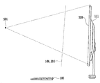
도 1은, 본 실시형태의 조작입력 시스템의 일례를 나타내는 도면이다. 본 실시형태에서는, 후술하는 바와 같이, 조작자(102)의 머리부를 기준으로 하여 우측영역(124) 및 좌측영역(125)을, 각각 오른손(114) 및 왼손(115)의 조작영역으로 정하고, 각각 조작내용을 판정하여 조작입력으로서 처리한다. 도 1을 참조하면 이해할 수 있는 바와 같이, 우측영역(124) 및 좌측영역(125)을 일정한 거리를 두고 배치함으로써, 조작자의 오른손(114) 및 왼손(115)의 움직임이 복잡하게 뒤얽혀 어떤 움직임인지 오인식하는 것을 회피할 수 있다.1 is a diagram showing an example of an operation input system of the present embodiment. In this embodiment, the
이와 같이 2개의 영역을 정함으로써, 도 20에 나타내는 바와 같이 디스플레이(111)에 상대하여, 오른손(114) 및 왼손(115)에서 상이한 종류의 조작을 행하여, 보다 효율적인 조작판정이 가능해진다. 예를 들어, 본 실시형태에서는, 오른손(114)으로 커서를 이동시키고, 왼손(115)으로 조작내용을 확정(마우스의 클릭에 상당)하도록 구성할 수 있는데, 이것으로 한정되지 않고 다양한 조작을 조합할 수 있다.By determining the two areas as described above, different types of operations are performed in the
본 실시형태의 디스플레이(111)는, 조작자(102)의 앞면에 배치되고, 조작자(102)는 디스플레이(111)와의 사이의 좌우 일정한 위치에 설정된 영역 내에서, 손가락 등의 형상이 조작판정 대상이 되는 것을 인식하여 조작을 행할 수 있다. 여기에서, 디스플레이(111)에는, 통상 PC에서 사용되는 다양한 어플리케이션용의 다양한 영상이 표시되는데, 이것과 더불어 조작입력을 지원, 즉 예를 들어 대상이 되는 조작자(102)의 부위 등을 화면의 구석 쪽에 표시하고, 조작자(102)에게 현시점에서 시스템이 어떠한 조작이 행해지고 있다고 인식하고 있는지를 표시할 수 있다. 본 실시형태에서는, 조작자가 시청하는 모니터로서, 통상의 PC용 디스플레이를 사용할 수 있다. 또한, 본 실시형태에서는, 오른손으로 위치결정을, 왼손으로 조작판정을 행하는 시스템을 사용하여 설명하였는데, 이것으로 한정되지 않고, 잘 쓰는 쪽의 손이나 조작자의 기호 등에 의하여 좌를 반대로 할 수도 있다.The
본 실시형태에서는 도 5에 나타내는 바와 같이 화상을 취득하기 위하여 비디오 카메라(511~514) 중 어느 한 위치의 카메라를 사용한다. 여기에서, 도 5에서는, 4개의 카메라가 나타나 있는데, 어느 1개 또는 2개 이상을 설치할 수 있다. 복수의 카메라를 사용할 때에는, 좌우 카메라로 좌우 손의 움직임을 각각 촬영하여, 화상의 정밀도를 높일 수도 있다. 또한, 카메라로서는 적외선 카메라 등, 본 기술분야에서 알려진 어떤 촬상수단을 사용할 수도 있고, 도 5와 같은 4개의 위치 이외에도 설치장소로서 모니터 부근의 어떤 곳을 선택할 수도 있다. 따라서, 카메라(511) 등은 대상의 화상을 촬영할 수 있는 것이라면 어떤 형태의 것이어도 좋으며, 그 방식에 대해서는 상관없지만, 설치 레이아웃 상 넓은 각도 범위를 취득할 수 있는 카메라인 것이 바람직하다.In this embodiment, as shown in Fig. 5, cameras at any one of the
또한, 최근 PC 등에서 사용되고 있는 값싼 웹카메라 등도 사용할 수 있다. 고가의 카메라 대신에, 저렴한 웹카메라를 이용하여, 카메라(512, 514)와 같이, 각 카메라를 대상화면의 양단에 설치하고, 상술한 바와 같이 좌우 카메라 각각에 왼쪽 조작, 오른쪽 조작 센싱을 독립적으로 담당하게 하는 방법에 의하여 센싱 정밀도를 높일 수도 있다. 이러한 경우, 취득된 이차원적인 화상정보로부터, 잘 쓰는 팔로 커서 이동(손가락 끝의 화상인식), 또 다른 팔의 제스처의 윤곽화상인식으로 의사결정하는 등의 본 기술분야에서 알려진 방법으로 조작을 이단계로 한 PC조작이 가능해진다.In addition, an inexpensive web camera used in recent PCs and the like can also be used. Instead of an expensive camera, an inexpensive web camera may be used to install each camera at both ends of the target screen, such as the
다음으로, 본 실시형태의 조작입력방법을 도 19를 참조하여 보다 구체적으로 설명한다. 도 19는, 본 실시형태의 조작입력 시스템의 일례를 나타내는 도면이다. 도 19를 참조하면, 본 실시형태의 조작은, 도 19의 예에서는 꽤 큰 완충영역, 즉 상술한 시점(501)과 조작대상화면(520)의 네 모서리를 연결하는 사각추를 사이에 두고 좌우로 나뉘어진 영역(124, 125) 내에서 손을 움직였을 때에만 조작대상으로 하므로, 조작입력동작으로 조작자가 손을 움직여도 디스플레이(111)에 표시된 화면을 차단하지 않고, 통상의 PC 조작시의 시인성을 확보할 수 있다. 여기에서, 좌우 손의 얽힘이 일어나지 않는 이상, 완충영역은 어떠한 크기로 할 수도 있다. 또한, 마찬가지로 좌우 동작하는 영역(124, 125)은 상술한 완충영역에 의하여 분할배치되어 있으므로, 각각의 영역에서의 동작을 조작자의 왼손, 오른손으로 정확하게 구별한 판정이 가능해진다. 종래의 통상의 제스처 인식에 있어서는, 조작자의 양팔의 교차나 신체와 팔의 겹침 등으로, 오인식이 발생하는 경우가 많았는데, 이에 따라, 조작자에 의한 조작영역설정이나 중앙의 비센싱 영역에 의하여 분할된 좌우 손의 조작영역을 각각 제한하여 구별할 수 있게 되어, 안정된 조작을 실현할 수 있게 된다.Next, the operation input method of the present embodiment will be described more specifically with reference to Fig. 19 is a diagram showing an example of the operation input system of the present embodiment. 19, the operation of the present embodiment is similar to that of the embodiment shown in Fig. 19, except that a quadrangular pyramid connecting the four corners of the above-described
본 실시형태에서는, 좌우 어느 한 손을 XY좌표의 포인팅 또는 포커스(종래의 마우스 의한 커서 이동에 상당) 기능에만 사용하도록 하고(가상 드래그 패드의 기능), 또 다른 쪽 손을 포커스에 대한 결정동작, 예를 들어 클릭, 더블클릭, 드래그의 트리거를 접수하는 기능에만 사용한다. 이렇게 하여, 좌우 각각에 완전히 기능을 분담하고, 2단계로 조작을 판단함으로써 제스처 조작에 많이 보이는 입력 실수나 오인식을 압도적으로 저감할 수 있다. 한편, 구체적인 제스처로서는, 손바닥을 펴고(가위바위보의 보의 형태) '클릭, 더블클릭 조작'으로 하거나, 검지를 세우고 클릭, 손가락 2개를 세우고 더블클릭 등으로 하거나 할 수 있다. 한편, 이하 편의상 오른손을 가상 트랙 패드 기능으로서 사용하고, 왼손을 조작결정 기능으로서 사용하였는데, 이것으로 한정되지 않고 좌우를 반대로 하거나, 기능을 더욱 분할, 또는 통합시키거나 할 수 있다.In the present embodiment, either one of the right and left hands is used only for the function of pointing or focusing the XY coordinate (corresponding to the cursor movement by the conventional mouse) (function of the virtual drag pad) For example, it is used only to accept triggers of clicks, double-clicks, and dragging. In this way, the functions are fully allocated to each of the left and right sides, and an operation mistake is judged in two steps, thereby making it possible to overwhelm the typing mistakes and mistakes that are often seen in the gesture operation. On the other hand, as a specific gesture, it is possible to perform a "click, double-click operation" by stretching the palm of the hand (a form of the scissors rock), or by setting the index finger and clicking, On the other hand, for the sake of simplicity, the right hand is used as a virtual track pad function and the left hand is used as an operation determining function. However, the present invention is not limited to this, and the left and right can be reversed or functions can be further divided or integrated.
(본 실시형태의 시스템 구성)(System Configuration of Present Embodiment)
도 2는, 본 실시형태의 조작입력장치의 컴퓨터(110)의 구조를 모식적으로 나타내는 블록도이다. 컴퓨터(110)에는, 디스플레이(111)에 설치되고, 조작자(102) 등을 촬영하는 비디오 카메라(511) 등이 접속되며, 촬영한 화상을 컴퓨터(110)에 입력한다. 촬영에 의하여 얻어진 화상은, CPU(210)에 있어서 본 실시형태의 특징인 조작자의 일부인 좌우 손의 화상을 추출한다. 컴퓨터(110)는, 일반적으로 CPU(210)를 구비하고, ROM(2111) 등에 기록된 프로그램을 RAM(212) 상에서 실행하며, 조작입력장치로부터 입력한 화상에 근거한 처리결과를 디스플레이(111) 등에 출력한다. 본 실시형태에서는, 디스플레이(111)는, 상술한 조작자의 손의 동작에 의하여 표시되는 아이콘 등 이외에, 조작자가 체험하고자 하는 다양한 어플리케이션에 의하여 제공되는 다양한 영상을 출력할 수 있으며, 또한 후술하는 바와 같이 조작입력의 지원이 되는 정보도 표시한다.2 is a block diagram schematically showing the structure of the
도 21은, 본 실시형태의 컴퓨터(110)의 CPU(210) 내에서 처리되는 프로그램의 기능 모듈의 일례를 나타내는 블록도이다. 도 21에 나타내는 바와 같이, 본 시스템에서의 처리는, 화상판독부(301), 화상추출부(302), 화상위치산출부(303), 조작판정부(304) 및 표시제어부(305)에 의하여 실행된다. 한편, 본 실시형태에서는, 비디오 카메라(511)로부터의 화상을 접수하고나서 데이터의 출력을 행할 때까지의 처리를 이 5개의 모듈에 의하여 실행하는데, 이것으로 한정되지 않고, 그 밖의 모듈을 사용하거나, 또는 보다 적은 모듈로 처리할 수도 있다.21 is a block diagram showing an example of a function module of a program to be processed in the
또한, 본 실시형태에서는, 디스플레이(111)로서 입체표시 가능한 3D 디스플레이를 사용하여, 조작자(102)로부터 보아 조작면이 설정 또는 조정된 위치에 존재하는 것처럼 보이도록 아이콘을 표시할 수도 있다. 이에 따라, 조작자(102)는, 마치 아이콘 등이 거기에 존재하는 것처럼 입체영상으로서 인식하고, 인식한 입체영상에 대하여 손이나 손가락을 사용하여 조작을 실행할 수 있다. 조작자(102)는, 그 오른쪽 눈과 왼쪽 눈에 의하여 디스플레이(111) 상에 표시된 화상 및 아이콘 등을 보는데, 아이콘 등은 입체표시하므로, 예를 들어 시차를 포함한 2매의 화상으로 이루어져 있으며, 각각 오른쪽 눈 및 왼쪽 눈으로 보는 것을 통하여 디스플레이(111)로부터 조작자의 앞면에 있는 것과 같이 입체표시되는 면을 형성할 수 있다. 한편, 입체표시되는 면의 위치는, 조작자의 조작감으로서 실제로 아이콘 등이 형성되는 위치와는 약간 다른 위치에 표시하는 경우도 있는데 반드시 일치할 필요는 없다.Further, in the present embodiment, an icon may be displayed such that the operating surface appears to exist at a set or adjusted position, as viewed from the
(조작영역의 설정)(Setting of operation area)
도 3은, 본 실시형태의 조작영역을 설정하는 처리를 설명하기 위한 도면이다. 본 실시형태에서는, 좌우 조작영역을 보다 간이하게 설정하기 위하여, 상술한 비디오 카메라(111)에 의하여 촬상된 조작자의 화상으로부터, 얼굴면(131)을 추출하여 좌우 영역의 설정시의 기준으로 한다. 도 3을 참조하면, 본 기술분야에서 알려진 방법으로 조작자(102)의 얼굴면(131)을 추출한 후, 얼굴의 중심부를 판단하여, 중심부를 통과하는 수직선을 조작자(102)의 중심선(132)으로 판단한다. 이러한 중심선의 좌우에, 어떠한 조작영역도 되지 않는 일정한 완충영역을 설치하고 좌우 조작영역(125, 124)을 설정한다. 이렇게 하여, 보다 간이하게 도 6에 나타내는 바와 같은 우측영역(124) 및 좌측영역(125)을 중심선(132)에 근거하여 정할 수 있는데, 각 조작영역의 크기, 위치는, 시스템이나 조작자의 체계 등에 따라서 적절한 값으로 한다. 마찬가지로 완충영역도 좌우 손의 움직임의 복잡한 정도에 따라서, 적절한 크기를 설정한다. 한편, 본 실시형태에서는 얼굴면을 추출하는데, 머리부 자체, 또는 그 밖의 머리부 근방에 있는 조작자의 일부를 기준으로 할 수도 있다.Fig. 3 is a diagram for explaining processing for setting an operation area according to the present embodiment. In this embodiment, the
본 실시형태에서는, 이와 같은 유효한 동작범위의 설정처리는, 시스템의 전원 투입 후나 특정 조작, 예를 들어 리모콘으로 지시하는 등에 의하여 개시되는데, 이것으로 한정되지 않고 본 기술분야에서 알려진 어떠한 방법, 타이밍으로 개시할 수 있다.In the present embodiment, the setting process of such an effective operation range is started after the power of the system is turned on or by a specific operation, for example, by a remote controller. However, the present invention is not limited to this and any method and timing .
또한, 본 실시형태에 있어서는, 통상의 PC 조작으로 도 18에 나타내는 바와 같은 양 팔꿈치를 붙인 제스처 입력이 일반적인 형태가 되므로, 동작 범위의 설정에 있어서는, 이와 같은 조작 자세를 고려하여 조작자의 신체에 적합한 위치에 범위 설정하는 것이 유용하다. 한편, 이와 같은 양 팔꿈치를 붙인 조작 자세에 의하면, 종래의 PC 조작에서의 마우스나 키보드에 비하여, 양팔의 무게의 의한 양 어깨로의 근육의 부담이 꽤 경감되는 것, 필요최소한의 움직임의 제스처 조작만으로 가능한 것으로부터, 신체적인 부담이 대폭 경감되며, 또한 마우스, 키보드를 카메라대에 바꿔 놓을 수 있게 되기 때문에 큰 잠정이 된다. 이와 더불어, 양팔꿈치를 책상면에 붙임으로써, 오른손(114)에 의한 커서 이동(포커스)이나, 왼손(115)에 의한 조작판정시에도 항상 안정적인 제스처 위치를 확보할 수 있다.Further, in the present embodiment, the gesture input with both elbows as shown in Fig. 18 is formed in a general form by a normal PC operation. Therefore, in setting the operation range, It is useful to set the range to the position. On the other hand, according to the manipulation posture in which both the elbows are attached, the burden on the muscles of both shoulders due to the weight of both arms is considerably reduced as compared with the mouse or keyboard in the conventional PC manipulation, The physical burden is greatly reduced, and the mouse and the keyboard can be replaced with the camera stand, which is a great provisional measure. In addition, by attaching both the elbows to the desk surface, it is possible to always secure a stable gesture position even when the cursor is moved by the right hand 114 (focus) or when the operation by the
본 실시형태에서는, 이상의 조작 범위 설정처리를 행하는 전제로서, 본 기술분야에서 알려진 초기설정, 예를 들어 본 실시형태의 조작입력장치가 새롭게 설치된 경우를 상정하면, 사전준비로서 이용하는 비디오 카메라(511)의 이용 렌즈의 왜곡, 디스플레이(111)와 렌즈와의 거리 등의 정보를 장치에 입력해 둘 필요가 있다. 더욱이 임계값 설정 등을 미리 조정해 둔다.In the present embodiment, assuming that an initial setting known in the art, for example, a case where the operation input device of this embodiment is newly installed, is set as a premise for performing the above-described operation range setting processing, the
더욱이, 도 24에 나타내는 바와 같이, 책상 위를 유효한 동작 범위로 할 수도 있다. 즉, 오른손(114)으로 책상 위를 이동시켜서 아이콘을 이동시키고, 왼손(115)은 통상 책상 위에 띄워 두고, 책상 면에 접촉하면 조작으로 판정하도록 할 수도 있다.Further, as shown in Fig. 24, the effective range of operation can be set on a desk. That is, the icon may be moved by moving the
(본 실시형태의 조작판정처리)(Operation determination processing of the present embodiment)
본 실시형태에서는, 도 4 및 도 19를 참조하면, 비디오 카메라(511) 등으로 촬영한 조작자(102)의 일부인 손이나 손가락(114, 115)의 위치를 정하는 동시에, 이들 위치와 디스플레이 상의 대응하는 점과의 상대적인 위치나 형상에 근거하여, 디스플레이 상의 아이콘을 이동시키거나, 일정한 조작으로 판정하거나 한다. 우선, 화상판독부(301)에 있어서 비디오 카메라(511) 등으로 촬영된 데이터를 판독하고, 그 데이터로부터 조작자의 손의 화상을 화상추출부(302)에 의하여 추출한다(S401 및 S402).4 and 19, the position of the hand or the finger 114 (115), which is a part of the
이와 같은 준비 결과, 상술한 조작영역의 설정으로 미리 설정하고(S403), 저장수단 등에 저장하고 있던 유효한 동작영역(124, 125)의 위치, 크기를 판독한다. 여기에서, 오른손의 조작개시위치를 적당하게 정해 두고, 본 기술분야에서 알려진 어떠한 방법으로 오른손(114)의 위치에 대응하는 디스플레이(111) 상의 위치에 아이콘 등이 표시제어부(305)에 의하여 표시되며, 손의 움직임과 함께 이동하도록 제어된다. 따라서, 조작자는 표시된 아이콘의 움직임에 맞추어 유효한 동작영역(124) 내에서 정확하게 손가락이나 손을 움직임으로써, 표시면에 표시된 아이콘을 이동하는 등의 조작을 행할 수 있다(S404, 405 및 408).As a result of the preparation, the setting of the operation area is set in advance (S403), and the positions and sizes of the
조작판정부(304)는, 조작자(102)의 동작영역(125) 내의 왼손(115)의 형상이나 움직임에 의하여, 미리 정한 조작이 이루어졌다고 판단하고, 오른손(114)의 위치에 근거하여 왼손의 형상 또는 움직임에 관련지어 미리 정해진 조작내용과 함께 조작이 조작이 실행된 것을 시스템에 통지한다(S406 및 S407).The
여기에서, 어떠한 형상, 움직임이 어떠한 조작에 대응하는지는, 시스템 독자적으로 결정할 수도 있고, 본 기술분야에서 알려진 어떠한 수법을 적용하여 결정할 수도 있다. 또는 단독으로 그 위치가 조작자에 의하여 접촉된, 예를 들어 아이콘이 선택되고, 혹은 버튼이 눌렸다고 판정할 수 있다. 판정한 결과는, 그러한 조작의 입력이 있었던 것으로서 컴퓨터(110)로 실행된다. 조작내용의 판정은 여기에서 설명한 수법으로 한정되지 않고, 본 실시형태에서 알려진 어떠한 방법도 사용할 수 있다. 또한, 구체적인 판정방법도 생략하였는데, 일반적으로는 미리 정한 제스처 등의 조작자의 신체의 형상, 움직임과, 그것이 의미하는 조작내용을 데이터 베이스 등에 저장해 두고, 화상추출 후, 이 데이터 베이스에 액세스하여 조작내용을 판정한다. 이때에도 물론, 화상인식기술이나 인공지능 등을 본 기술분야에서 알려진 수법에 의하여 이용하고, 판정 정밀도를 향상시킬 수도 있다. 여기에서, 손이 유효한 동작영역(124, 125)에 없는 경우에는 조작으로는 판정되지 않는다. 예를 들어, 오른손이 유효한 영역(124)을 벗어나면, 그 위치에서 아이콘이 정지하던지, 초기 위치로 되돌아간다. 그리고, 왼손이 유효한 영역(125)을 벗어나면 미리 정한 형상이나 움직임으로도 조작으로는 판정되지 않는다.Here, it can be determined by the system on its own, which shape and motion corresponds to which operation, or by any technique known in the art. Or alone can determine that the position has been touched by the operator, e.g., the icon has been selected, or the button has been depressed. The determination result is executed by the
이상, 본 실시형태에 따르면, 조작자의 머리부 등을 기준으로 좌우의 동작영역(124, 125)을 정하고, 좌우 손에서 다른 기능, 예를 들어 아이콘의 이동 또는 선택과, 클릭, 드래그 등의 조작내용으로 분별하여 실행함으로써, 제스처만의 입력에도 불구하고, 조작자에게 부담을 주지 않고, PC 등에서 키보드를 사용하지 않는 정확한 조작입력이 가능해진다.As described above, according to the present embodiment, the left and
(제 2 실시형태)(Second Embodiment)
상술한 제 1 실시형태에서는, 조작자와 디스플레이와의 사이에서 좌우로 기능을 분담하여 손을 움직이는 것에 의한 조작입력방법 중에서도, 좌우 조작영역을 조작자의 중심선에 근거하여 정하는 방법에 대하여 설명하였는데, 본 실시형태에서는 기본적으로 같은 시스템 구성을 사용하여, 조작자의 제스처 등, 손 등의 위치나 동작 등에 의하여, 중심선을 고려하지 않고 조작영역을 정하는 것이다. 또한, 본 실시형태에서는 기본적으로 좌우 손을 각각 디스플레이로부터 보아 왼쪽 및 오른쪽의 일정한 범위에서 움직여서 조작을 판정하는데, 이것으로 한정되지 않고, 손이 자연스럽게 닿는 범위의 위치에서 손을 움직임으로써 조작판정에 사용할 수도 있다. 예를 들어, 도 19에 나타내는 시점(501)과 표시면(520)으로 형성되는 사각추의 아래측을 스페이스키로서 사용하는 등, 다양한 기능을 설정할 수 있다.In the above-described first embodiment, the method of determining the left and right operating regions based on the center line of the operator among the operation input methods by moving the hand by sharing the functions between the operator and the display has been described. However, In the form, basically the same system configuration is used to determine the operation area without taking the center line into consideration, such as the position or the operation of the hand, such as the gesture of the operator. In the present embodiment, the operation is basically determined by moving the left and right hands from the display in a predetermined range from the left and right, respectively. However, the present invention is not limited to this. It is possible. For example, various functions can be set, such as using the space below the quadrangle formed by the
본 실시형태의 조작입력방법에서도, 도 19에 나타내는 바와 같이, 본 실시형태의 조작은, 상술한 시점(501)과 조작대상화면(520)의 네 모서리를 연결하는 사각추를 사이에 두고 좌우로 나뉜 영역(124, 125) 내에서 손을 움직였을 때에만 조작대상으로 하므로, 조작입력동작으로 조작자가 손을 움직여도 디스플레이(111)에 표시된 화면을 차단하지 않고, 통상의 PC 조작시의 시인성을 확보할 수 있다. 제 1 실시형태에서는, 이와 같은 사각추도 포함하는 완충영역이라는 개념을 이용하여 좌우영역을 사이에 두었지만, 본 실시형태에서는 원칙적으로 좌우의 동작하는 영역(124, 125)은 상술한 사각추에 의하여 분할배치하여 처리를 실행하는 손, 오른손과 정확하게 구별한 판정이 가능해진다. 종래의 통상의 제스처 인식에 있어서는, 조작자의 양팔의 교차나 신체와 팔과의 겹침 등으로, 오인식이 생기는 경우가 많았지만, 이에 의하여, 조작자에 의한 조작영역설정이나 중앙의 비센싱 영역에 의하여 분할된 좌우의 손의 조작영역을 각각 제한하여 구별할 수 있게 되어, 안정된 조작을 실현할 수 있게 된다.19, the operation of the present embodiment is divided into left and right portions by passing a quadrangle that connects the four corners of the
(제 2 실시형태의 조작범위의 설정)(Setting of the operation range of the second embodiment)
본 실시형태에서는, 조작범위 설정처리를 행하는 전제로서, 본 기술분야에서 알려진 초기설정, 예를 들어 본 실시형태의 조작입력장치가 새롭게 설치된 경우를 상정하면, 사전준비로서 이용하는 비디오 카메라(511)의 이용 렌즈의 왜곡, 디스플레이(111)와 렌즈와의 거리 등의 정보를 장치에 입력해 둘 필요가 있다. 더욱이, 임계값 설정 등을 미리 조정해 둔다. 시스템의 초기설정이 종료되면, 본 실시형태의 처리를 행하는데, 도 20을 참조하여, 본 실시형태에 따른 조작자의 제스처에 의하여 좌우 동작 범위를 설정하는 처리를 설명한다. 도 20에 나타내는 예와 같이, 카메라로 촬영된 조작자의 화상의 손(114, 115)에 의하여 동작범위의 위치, 크기가 결정된다. 구체적으로는, 도 20에 나타내는 바와 같이, 조작자가 손(114, 115)으로 나타낸 위치를 포함하는 일정한 범위가 유효한 동작 범위로서 설정된다. 동작 범위의 예로서, 도 19에 범위(124, 125)를 나타낸다. 여기에서, 상술한 사각추에 의하여 좌우의 유효한 범위를 분할배치하므로, 설정된 범위가 상술한 사각추에 따른 부분은 유효한 동작으로는 간주되지 않고, 따라서 유효한 동작 범위로부터 제외된다. In the present embodiment, assuming that the initial setting known in the art, for example, the case where the operation input device of the present embodiment is newly installed, is set as a premise for performing the operation range setting processing, the
본 실시형태에서는, 이와 같은 유효한 동작범위의 설정처리는, 시스템의 전원투입 후나 특정 조작, 예를 들어 리모컨으로 표시하는 등에 의하여 개시되는데, 이것으로 한정되지 않고 본 기술분야에서 알려진 어떠한 방법, 타이밍으로 개시할 수 있다. In the present embodiment, such effective operation range setting processing is started after the system is powered on or by a specific operation, for example, by a remote controller. However, the present invention is not limited to this, and any method and timing .
또한, 본 실시형태에 있어서는, 통상의 PC 조작에서 도 18에 나타내는 바와 같은 양팔꿈치를 댄 제스처 입력이 일반적인 형태가 되므로, 조작 범위의 설정에 있어서는, 이와 같은 조작자세를 고려하여 조작자의 신체에 적합한 위치에 범위설정하는 것이 유용하다. 한편, 이와 같은 양팔꿈치를 댄 조작자세에 의하면, 종래의 PC 조작에서의 마우스나 키보드에 비하여, 양팔의 무게에 의한 양 어깨로의 근육 부담이 꽤 경감되는 것, 필요최소한의 작은 제스처 조작만으로 가능한 것으로부터, 신체적인 부담이 대폭 경감되며, 마우스, 키보드를 카메라대에서 바꿔 놓을 수 있게 되므로 큰 이점이 된다. 이와 더불어, 양팔꿈치를 책상 면에 댐으로써, 오른손(114)에 의한 커서 이동(포커스)이나, 왼손(115)에 의한 조작판정시에도 항상 안정적인 제스처 위치를 확보할 수 있다.Further, in the present embodiment, the gesture input with both elbows as shown in Fig. 18 becomes a general form in the normal PC operation. Therefore, in setting the operation range, It is useful to set the range to the position. On the other hand, according to the manipulated posture in which both elbows are applied, the muscular load on both shoulders due to the weight of both arms is considerably reduced as compared with the mouse or keyboard in the conventional PC manipulation, The physical burden is greatly reduced, and the mouse and the keyboard can be changed from the camera stand, which is a great advantage. In addition, by dangling both elbows on the desk surface, a stable gesture position can always be ensured even when the cursor is moved by the
더욱이, 도 24에 나타내는 바와 같이, 책상 위를 유효한 동작범위로 할 수도 있다. 즉, 오른손(114)으로 책상 위를 이동시켜 아이콘을 이동시키고, 왼손(115)은 통상적으로 책상 위에 띄워 놓으며, 책상면에 접촉하면 조작으로 판정하도록 할 수도 있다.Further, as shown in Fig. 24, the effective range of operation can be set on a desk. That is, the icon is moved by moving the
이상, 본 실시형태에 따르면, 표시화면의 시계(視界), 즉 상술한 사각추에 의하여 명확하게 분리되는 좌우의 동작범위(124, 125)를 정하고, 좌우의 손에서 다른 기능, 예를 들어 아이콘의 이동 또는 선택과, 클릭, 드래그 등의 조작내용으로 분별하여 실행함으로써, 제스처만의 입력에도 불구하고, 조작자에게 부담을 주지 않으며, PC 등에서 키보드를 사용하지 않는 정확한 조작입력이 가능해진다.As described above, according to the present embodiment, the left and right motion ranges 124 and 125 that are clearly separated by the clock (sight field) of the display screen, that is, the above- The user can perform precise operation input without using the keyboard in a PC or the like without burdening the operator in spite of inputting only the gesture.
(제 3 실시형태)(Third Embodiment)
상술한 제 1 및 제 2 실시형태에서는, 조작자와 디스플레이와의 사이에서 좌우로 기능을 분담하여 손을 움직이는 것에 의한 조작입력에 대하여 설명하였는데, 본 실시형태에서는 기본적으로 같은 시스템 구성을 사용하여, 더욱 정밀도가 높은 조작입력을 가능하게 한다. 즉, 본 실시형태에서는, 가상적인 조작면의 개념을 도입하여, 조작면에 대한 손의 움직임이나 조작면에 의하여 형성되는 영역을 이용하여, 조작의 트리거나 조작내용을 판정한다. 이 때문에, 본 실시형태에서는 제 1 실시형태의 카메라 대신에 삼차원 카메라를 사용함으로써, 조작자 자신, 손 또는 손가락의 z방향의 위치도 취득하여, 가상적인 조작면 상의 손의 위치를 정확하게 취득하거나, 조작면을 가로질렀는지 아닌지를 판정하거나 할 수 있다. 따라서, 삼차원 카메라를 사용하는 점을 제외하고 시스템 구성은 제 1 실시형태와 같으므로, 이하 중복되는 점은 생략한다. 한편, 본 실시형태의 가상적인 조작면을 사용한 처리는, 좌우 조작의 쌍방에 적용할 수 있는데, 오른쪽 또는 왼쪽 중 어느 한쪽 조작에 상술한 제 1 실시형태의 처리를 적용하고, 또 다른 쪽에 본 실시형태의 처리를 적용할 수도 있어, 시스템의 구성이나 사용 상황에 맞추어 적절히 선택할 수 있다.In the first and second embodiments described above, the operation input by moving the hand by dividing the functions between the operator and the display has been described. In the present embodiment, basically the same system configuration is used, Thereby enabling highly precise operation input. That is, in the present embodiment, the concept of a virtual operation surface is introduced, and the operation of the operation or the content of the operation is determined by using the area formed by the movement of the hand or the operation surface with respect to the operation surface. Therefore, in this embodiment, by using the three-dimensional camera instead of the camera of the first embodiment, it is possible to acquire the position of the operator itself, the hand or the finger in the z direction, to accurately acquire the position of the hand on the virtual operation surface, It is possible to judge whether or not the surface has been crossed. Therefore, the system configuration is the same as that of the first embodiment, except that a three-dimensional camera is used, so that duplicate points will be omitted below. On the other hand, the processing using the hypothetical operation surface of the present embodiment can be applied to both the right and left manipulations. The processing of the above-described first embodiment is applied to either the right or left manipulation, Processing can be applied, and it can be appropriately selected in accordance with the configuration and use situation of the system.
도 5는, 본 발명의 일 실시형태에 따른 좌우 가상적인 조작면을 설명하기 위한 도면이다. 도 5에 나타내는 비디오 카메라(511~514) 중 실제 시스템에서 사용하는 경우는, 기본적으로 삼차원 카메라 1대면 된다. 본 실시형태에서는 비디오 카메라(511)로서 삼차원(또는 3D) 카메라를 이용함으로써, 조작자를 포함하여 입체화상을 작성할 수 있도록 한다. 물론, 좌우로 통상의 이차원 카메라를 배치하여 사용할 수도 있다. 예를 들어, 비디오 카메라(512, 514)의 양쪽을 구비하도록 하고, 이 경우에 카메라로서는 이차원 카메라를 사용하여 비디오 카메라(512, 514)의 2대로 입체화상을 생성하도록 할 수도 있다.5 is a view for explaining a left and right virtual operating surface according to an embodiment of the present invention. In the case of using one of the
도 9 및 도 10은, 조작면을 측면에서 본 도면 및 상면에서 본 도면이다. 도 9 및 도 10을 참조하면 이해할 수 있는 바와 같이, 조작면(104, 105)은, 조작자의 시점(501)과 조작대상화면(520)의 네 모서리를 연결하는 사각추를 피할 수 있도록 좌우에 배치한다. 여기에서, 위치결정면(104) 및 조작판정면(105)의 위치는, 후술하는 PC 설치단계의 초기설정단계에서 조작자가 이용환경에 맞추어, 입력조작에 최적인 위치에서 양손을 벌리고 설정한다. 이때, 예를 들어, 카메라측에서 조작자의 머리부 양 어깨 등의 상반신 위치정보나 양쪽 눈의 위치 등도 보충하여, 책상을 향한 조작자가 팔꿈치를 댄 상태로 양손의 조작을 하기 쉬운 좌우 대조위치에 배치설정하는데, 이것으로 한정되지 않고, 조작자의 조작환경에 최적으로 설정할 수 있다. 한편, 도 9 및 도 10에 나타내는 위치결정면(104) 및 조작판정면(105)은, 상술한 사각추를 피하도록 좌우에 배치되어 있는데, 이것은 상술한 바와 같이 조작자의 시계를 조작시의 손(114, 115)이 차단되지 않도록 하기 위해서이며, 따라서 이러한 목적을 달성할 수 있는 이상, 위치결정면(104) 및 조작판정면(105)은 대략 좌우에 배치되어 있으면 되고, 사각추에 다소 걸려있어도 문제는 없다.Figs. 9 and 10 are views seen from the side and the upper side of the operation surface. Fig. 9 and 10, the operation surfaces 104 and 105 are disposed on the left and right sides so as to avoid a tetrahedron connecting the four corners of the operator's
도 11 및 도 12는, 본 발명의 일 실시형태에 따른 좌우 2개의 조작면의 전형적인 기능의 예를 설명하기 위한 도면이다. 도 11 및 도 12 모두 위치결정면(104)은 포인팅 또는 포커스의 기능을 담당하고, 예를 들어 도 7에 나타내는 바와 같이 위치결정면(104)에 대응하는 영역(1202)을 디스플레이(111)의 적당한 장소에 표시, 현재 손(114)이 포커스하고 있는 대응하는 부분의 색상을 바꾸거나, 도시하고 있지 않은 아이콘 등을 표시하거나 할 수 있다. 이와 같이 위치결정면(104) 상의 손(114)의 움직임에 연동하여, 디스플레이(111) 상의 화상을 바꿈으로써, 조작자는 직감적으로 디스플레이(111)를 보면서 손(114)으로 포커스할 수 있게 된다.Figs. 11 and 12 are diagrams for explaining typical functions of two right and left operating surfaces according to an embodiment of the present invention. Fig. 11 and 12, the
또한, 조작판정면(105)은, 도 11에 나타내는 바와 같이 일정 영역(901)을 가지게 하고, 조작판정면(105)을 손(115)이 넘으면 조작이 개시되었다고 판정하여, 영역(901) 내의 손(115)의 형상이나 제스처에 근거하여, 조작내용을 판정할 수 있다. 즉, 본 실시형태의 조작면은, 조작자(102)의 신장이나 팔의 길이, 또는 신장이나 어깨폭 등의 신체치수정보에 근거하여 설정되고, 조작자(102)는, 미리 설정한 조작판정면(105)이 가상적으로 존재한다고 파악하고, 다양한 조작을 하려고 하는 경우에는 조작판정면(105)을 기준으로 손(115)을 앞에 있는 조작영역(901)에 돌출하여 제스처를 나타내거나 할 수 있다.11, it is determined that the operation is started when the
또는, 도 12에 나타내는 바와 같이, 조작판정면을, 예를 들어 2계층(902, 1001)으로 하여 손(115)이 1계층째(1001)까지만 관통하고 있으면 클릭으로 판정하고, 2계층째(902)까지 도달하고 있으면 더블클릭으로 판정하도록 할 수 있다. 본 실시형태에서는, 조작판정면으로서 2계층을 가지는 예를 나타내었는데, 이것으로 한정되지 않고, 3계층이나 그 이상의 계층을 설정하여, 각각 다양한 기능을 대응시킬 수 있다. Alternatively, as shown in Fig. 12, if the operation judgment surface is, for example, the second hierarchy (902, 1001) and the
그리고, 예를 들어 도 7에 나타내는 바와 같은 예에서는, 본 실시형태의 조작입력 시스템은, 간이적인 키보드의 기능을 가지게 되는데, 도 8에 나타내는 바와 같이, 통상의 키보드 기능을 가지도록 할 수도 있다. 즉, 오른쪽 조작면(104)은 통상의 키보드의 오른쪽 절반을 할당하고, 왼쪽 조작면은 통상의 키보드의 왼쪽 절반을 할당함으로써, 조작자는 디스플레이(111) 상의 키보드 레이아웃(1202, 1301)을 보면서 포커스시켜서 조작을 결정할 수 있다. 한편, 이 경우의 조작의 결정에는, 통상은 이용하지 않는 조작화면 아래에 또 다른 1개의 조작면을 설정하는 등을 하여, 조작판정면으로 할 수도 있다. 또한, 이와 같은 조작화면 아래에 조작면을 설치하는 경우, 단순히 스페이스키를 할당하는 등을 할 수도 있다.For example, in the example shown in Fig. 7, the operation input system of the present embodiment has a simple keyboard function. As shown in Fig. 8, the operation input system may have a normal keyboard function. That is, the
(조작면의 설정)(Setting of operating surface)
본 실시형태에서는, 시스템의 초기설정이 종료되면, 본 실시형태에 따른 조작면의 설정처리를 행한다. 도 20에 나타내는 예와 같이, 삼차원 카메라로 촬영된 조작자의 화상의 손(114, 115)에 의하여 조작면의 형상(크기, 디스플레이에 대한 각도를 포함)이 결정되며, 예를 들어 z방향의 디스플레이로부터 손(114, 115)까지의 거리에 의하여 조작면(104, 105)의 위치를 결정한다. 구체적으로는, 도 1에 나타내는 바와 같이, 조작자가 손(114, 115)으로 나타낸 위치에 조작면(104, 105)을 형성하면 좋은 것이 이해된다.In the present embodiment, when the initial setting of the system is completed, the setting process of the operation surface according to the present embodiment is performed. The shape (size, including the angle with respect to the display) of the operation surface is determined by the
다음으로, 도 23을 참조하여 조작면 추출처리를 설명한다. 도 23은, 본 실시형태에 따른 지정된 조작면의 위치를 추출하는 처리를 나타내는 플로차트이다. 우선, 데이터, 즉 조작자의 입체화상 데이터의 입력이 이루어지면(S601), 손의 형상 및 머리부를 인식하고(S602, S603), 조작면을 형성할지 말지를 판정한다(S604). 구체적으로는, 예를 들어 팔꿈치를 책상 위에 대고 손을 드는 제스처를 일정시간 유지하고 있었을 때에는, 조작면의 설정처리라고 판단하고, 조작자가 손에 의하여 지시한 위치에 조작면을, 취득한 입체화상으로부터 추출하여 조작면을 형성하고(S605), 필요할 때에는 조작자의 신체의 측정값, 예를 들어 팔의 길이, 몸통이나 머리부의 위치에 근거하여 조작영역을 설정하며(S606) 데이터를 추출하여 종료한다(S609). 여기에서, 본 실시형태에서는 팔꿈치를 책상 위에 대고 손을 드는 움직임을 일정시간 정지함으로써, 조작면의 설정지시라고 판단하도록 하고 있는데, 이것으로 한정되지 않으며, 다양한 제스처, 리모컨 조작 등으로 지시하는 등의 본 기술분야에서 알려진 어떠한 수법에 의하여 지시를 판단하게 할 수 있다. 한편, 본 실시형태에서는 기본적으로 손에 의하여 형태가 만들어진 형상, 위치에 조작면을 형성하는데, 조작자의 신체적 특징이나 디스플레이의 위치, 사용 상황 등에 맞추어 조정할 수도 있다.Next, the operation surface extracting process will be described with reference to FIG. Fig. 23 is a flowchart showing processing for extracting the position of the designated operation surface according to the present embodiment. First, when input of data, that is, stereoscopic image data of the operator is performed (S601), the shape and head of the hand are recognized (S602 and S603) and it is determined whether or not the operation surface is formed (S604). More specifically, for example, when the elbow is held on a desk and a hand-lifting gesture is held for a predetermined period of time, it is determined that the setting of the operation surface is the setting process, and the operation surface is moved from the acquired stereoscopic image (S605). When necessary, the operation area is set based on the measured value of the operator's body, for example, the length of the arm, the position of the torso or the head (S606) S609). Here, in the present embodiment, the elbow is placed on the desk and the movement of lifting the hand is stopped for a predetermined time to determine that it is a setting instruction of the operation surface. However, the present invention is not limited to this and various gestures, Any instruction known in the art may be used to determine the indication. On the other hand, in the present embodiment, the operation surface is formed basically in the shape and position formed by the hand, and it can be adjusted according to the physical characteristics of the operator, the position of the display, the use situation and the like.
머리부의 인식이나 손의 제스처로부터 조작면의 설청처리가 아니라고 판단하면, 이미 조작면이 설정된 상태인지 아닌지를 판정하고(S607), 조작면이 설정되어 있는 경우에는 통상의 조작으로 판단하여 조작영역 내의 손의 위치를 취득한다(S608). 이상에 의하여 조작자의 지시에 근거하는 조작면의 설정처리를 행한다.If it is determined that the operation surface has not been set from the recognition of the head or the gesture of the hand, it is determined whether or not the operation surface has already been set (S607). If the operation surface has been set, The position of the hand is acquired (S608). Thus, the setting process of the operation surface based on the instruction of the operator is performed.
여기에서, 조작면의 형상은 도 1 등을 참조하면 수직으로 세운 직사각형으로 되는데, 이것으로 한정되지 않으며, 조작자의 조작상태에 따라 다양한 형상(크기, 디스플레이에 대한 각도를 포함)의 조작면을 형성할 수 있다. 예를 들어, 도 18에 나타내는 바와 같이, 책상 위에 위치결정면(1801) 및 조작판정면(1802)을 배치할 수도 있고, 키보드나 마우스를 사용하는 감각으로 조작입력을 할 수도 있다. 물론, 이러한 조작면의 배치로 하기 위해서는, 조작면의 설정시에 책상 위에 손을 놓거나, 미리 정한 제스처를 하거나 하여 조작면을 설정해 두면 된다.Here, the shape of the operation surface is a rectangle vertically set with reference to FIG. 1 and the like. However, the shape is not limited to this, and the operation surface of various shapes (including sizes, angles with respect to the display) can do. For example, as shown in Fig. 18, a
(본 실시형태의 조작판정처리)(Operation determination processing of the present embodiment)
본 실시형태에서는, 비디오 카메라(511) 등으로 촬영한 조작자(102)의 일부인 손이나 손가락(114, 115)의 위치를 정하는 동시에, 조작면(104, 105)과 조작자(102)의 손가락(114, 115)과의 위치관계를 산출하는 처리를 행한다. 이러한 처리에 대해서는 도 22를 참조하여 다음에 설명한다. In this embodiment, the positions of the hands or
도 22는, 본 실시형태의 조작판정처리의 플로차트이다. 우선, 화상판독부(301)에 있어서 비디오 카메라(511) 등으로 촬영된 데이터를 판독하고(S401), 그 데이터로부터 조작자의 모습을, 화상추출부(302)에 의하여 추출한다(S402). Fig. 22 is a flowchart of the operation determination processing of the present embodiment. First, data photographed by the
이러한 준비 결과, 상술한 조작면의 설정으로 미리 설정하고, 저장수단 등에 저장하고 있던 조작면의 위치, 형상을 판독한다(S403). 이와 같이, 조작면의 형상 및 위치가 판독되면, 본 기술분야에서 알려진 어떠한 방법으로, 조작면(104) 상의 손(114)의 위치에 대응하는 디스플레이(111) 상의 위치에 아이콘 등이 표시제어부(305)에 의하여 표시되고, 손의 움직임과 함께 이동하도록 제어된다. 따라서, 조작자는 표시된 아이콘에 대응하는 조작면 상의 위치에 정확하게 손가락이나 손을 접촉할 수 있게 되므로, 표시면에 표시된 아이콘을 터치하는 등의 조작을 행할 수 있다.As a result of this preparation, the position and shape of the operation surface stored in the storage means or the like are read out in advance (S403). When the shape and position of the operation surface are thus read out, an icon or the like is displayed on the
조작판정부(304)는, 조작입력 시스템이 형성한 조작면과, 조작자(102)와의 상대적인 위치관계를 이용하여(S404), 조작자(102)의 일부가 조작면의 비디오 카메라(511) 등에서 보아 앞쪽에 오면, 조작이 개시되었다고 판단하고(S405), 위치결정면(104) 상에서의 손(114)의 위치를 결정하며, 표시부의 대응하는 위치에 아이콘을 이동하는 동시에, 한쪽 조작판정면(105)을 기준으로 하여 손(115)의 형상(손을 벌리고 있거나, 또는 손가락 2개를 세우고 있는 등)이나 움직임으로터, 그 형상, 움직임이 미리 상정된 어떤 조작인지를 판정한다(S406). 판정한 결과는, 그러한 조작의 입력이 있었던 것으로 하여 컴퓨터(110)에서 실행되며(S407), 처음부터 조작면으로부터 앞쪽으로 손이 나와 있지 않은 경우, 조작은 이루어지지 않았다고 판정하여 종료한다(S408). 조작내용의 판정은 여기에서 설명한 수법으로 한정되지 않고 본 실시형태에서 알려진 어떠한 방법도 이용할 수 있다.The
(조작면의 앞쪽 조작지원)(Supports operation of the front side of the operating surface)
본 실시형태에서는, 조작자가 공간 상에 가상적으로 설정한 조작면을 기준으로, 그곳에 마치 마우스의 대체가 되는 입력기기가 존재하는 것처럼 조작함으로써, 그 조작내용을 확실하게 판정하고자 하는 것인데, 조작자의 일부인 손 또는 손가락 등이 조작면에 이를 때까지, 즉 조작자가 어떤한 조작을 실행하려고 손 또는 손가락을 움직이기 시작하면서부터 조작면을 누를 때까지의 동안에도 조작지원을 함으로써, 조작입력을 더욱 용이하게, 보다 정밀하게 행하도록 할 수 있다. 본 기능은, 특히 포인팅 또는 포커스 기능에 있어서 유효한데, 조작판정면을 사용한 조작판정에 있어서도 유효한 경우가 적지 않으므로, 일반적인 가상적으로 설정되는 조작면으로서 위치결정면을 예로 설명한다. In the present embodiment, it is intended to reliably determine the contents of the operation by operating as if there is an input device to be substituted for the mouse, based on the operation surface virtually set on the space by the operator, It is possible to support the operation even from the time when the hand or the finger or the like reaches the operation surface, that is, from when the operator starts moving the hand or the finger to perform a certain operation to when the operation surface is pressed, , So that it can be performed more accurately. This function is particularly effective for the pointing or focus function. Since the function is effective even in the operation judgment using the operation judgment surface, the positioning surface will be described as an example of the operation surface which is generally set virtually.
기본적으로는, 이러한 조작지원의 원리는 조작면에 대한 조작자의 부위, 예를 들어 손 또는 손가락의 위치의 움직임에 맞추어, 디스플레이(111) 상에 조작자가 어떠한 조작을 하려고 하고 있는지를 시각적으로 표시하게 함으로써, 조작자를 유도하여 정확한 조작입력을 가능하게 하는 것이다.Basically, the principle of this operation support is to visually display on the
이 점에 대하여, 도 14를 참조하여 설명하면, 본 실시형태에서는 미리 조작자가 조작면으로의 조작이 적합한 위치에 조작면(104)을 설정한다. 도 14에 나타내는 바와 같이, 조작자는 시스템에 대하여 어떠한 조작을 하려고 하는 경우, 본 실시예에서는 디스플레이(111)에 대하여, 팔(2401)을 앞뒤로 움직임으로써, 손 또는 손가락(114)의 위치가 변하므로, 그 모습을 디스플레이(111)에 표시하면, 돌출된 손가락(114)이 일정한 위치까지 오면, 그때 디스플레이(111)의 화면 상에서 지시된 항목이 실행되는 등, 시스템적으로 일정한 처리가 이루어진다. 도 14의 예에서는, 조작면(104)에 대한 손가락(114)의 위치(깊이)에 따라서 아이콘의 크기가 변하도록 되어 있고, 조작면에 가까워질수록 아이콘이 작아져서 조작자에게는 자기의 조작에 의하여 일정한 장소에 포커스되고 있는 것을 인식시킬 수 있도록 되어 있다. 그리고, 아이콘이 가장 작아진 위치에서 조작이 확정되고, 그에 따른 처리가 실행된다.With respect to this point, referring to Fig. 14, in the present embodiment, the operator sets the
이상의 조작 결과, 아이콘이 디스플레이(111)의 화면(2501) 상에서 어떻게 변하는지를 나타낸 것이 도 15이다. 도 15를 참조하면, 디스플레이(111)의 화면(2501)에는 예를 들어 텔레비전 프로그램표가 표시되어 있고, 어떤 프로그램에 관한 조작을 하려고 하고 있다. 이러한 상태에서, 예를 들어 조작자가 '설정변경'의 메뉴 버튼을 선택하고자 하는 경우, 조작자는 상술한 바와 같이 디스플레이(111)를 향하여 손가락(114)을 돌출하여 선택하려고 한다. 본 실시형태에서는, 손가락(114)이 조작면인 텔레비전 프로그램표에 대하여 일정한 거리까지 가까워지면, 화면(2501)에 아이콘(2503)이 표시된다. 이러한 아이콘은 손가락의 위치가 아직 멀기 때문에 도 14에 나타내는 아이콘 중 오른쪽에 있는 비교적 큰 것이 표시된다, 조작자가 팔(2401)을 더욱 뻗으면, 이 아이콘은 목표인 선택항목 '설정변경'에 가까워지면서, 작아져서 일정한 크기의 아이콘(2502)일 때에 특별한 아이콘이 된다. 여기에서, 본 실시형태의 조작판정면(105)에 의하여 어떠한 조작이라고 판정되면 아이콘을 상이한 형상이나 색상 등으로 바꾸어, 조작이 판정된 것을 나타낼 수 있다.15 shows how the icon changes on the
이와 같이, 도 15의 예에서는, 손가락(114)의 위치에 따라서 화면(2501)에 표시되는 아이콘의 크기를 바꿈으로써, 조작자는 자기 동작이 시스템에서 어떻게 인식되고 있는지를 파악할 수 있어, 조작면의 위치를 보다 인식하기 쉽게 하여, 메뉴의 선택 등의 조작을 행할 수 있다. 여기에서, 손가락(114), 팔(2401)을 포함하는 조작자 전체 및 각 부위의 위치나 크기는, 조작자의 전체형상과 같은 삼차원 카메라를 이용함으로써 추출할 수 있다. 이에 따라 화면 내의 물체는 안쪽깊이도 포함하여 파악할 수 있기 때문에, 이들 정보에 근거하여 조작면과의 거리나 위치관계를 산출할 수 있다. 단, 본 실시형태에서 사용하는 삼차원 카메라나 위치의 추출, 거리의 산출 등은 본 기술분야에서 알려진 어떠한 방법도 이용할 수 있으므로, 여기에서는 그 설명을 생략한다.15, by changing the size of the icon displayed on the
여기에서, 화면에 표시되는 아이콘은 원형으로 조작자의 동작에 맞추어 크기가 변하는데, 이것으로 한정되지 않으며 도 16에 나타내는 바와 같이 다양한 형태의 아이콘을 이용하여, 다양하게 변화시킬 수 있다. 즉, 도 16을 참조하면, (1)은 손가락 형태의 아이콘이고, 상술한 예와 마찬가지로 조작면에 가까워질수록 작아지게 되어 있다. (2)는 원형으로 점차 작아지도록 되어 있는데, 조작판정면에 의하여 입력 또는 선택이 확정되면 특별한 형상으로 변하여 확정된 것이 나타난다. 이러한 아이콘이나 다른 아이콘의 경우도 형상(크기, 디스플레이에 대한 각도를 포함)의 변화 대신에, 또는 이와 함께 아이콘의 색상을 바꿀 수도 있다. 예를 들어 청, 녹, 황, 적색 등으로 한색계에서 난색계로 변화시킴으로써, 직감적으로 조작이 포커스되어 확정되는 것을 조작자는 인식할 수 있다. (3)은 X와 같은 형상으로, 멀리에 있는 경우에는 클 뿐만 아니라 음영이 들어가 있고, 가까워질수록 아이콘의 크기가 작아지는 동시에 음영이 사라져 선명한 형상이 된다. (4)는 아이콘 전체의 크기는 변하지 않고, 안에 그려진 도형이 형상변화를 일으켜 포커스되는 모습을 인식하도록 되어 있다. 이 경우, 도형의 색상도 바꿀 수 있다. 도 16에 나타내는 (5)도 형상을 바꾸는 것이다. 도 23에 있어서, 손가락의 움직임에 따라서 아이콘의 형상이나 색상 등이 변해 가고, 조작면을 넘으면 그 순간에 란(2601)에 나타내는 바와 같이 다양한 형상이나 색상으로 바뀌거나, 점멸하거나 하여 조작으로서 판정되었음을 조작자에게 인식시킬 수도 있다. 그리고, 도시하지 않지만, 이 밖의 아이콘의 변화로서는 처음에는 투명하고 손가락이 조작면에 가까워질수록 불투명해지는 변화도 효과적이다. 더욱이. 도시하지 않지만, 후술하는 바와 같이 디스플레이의 입체표시기능을 별도로 설정하고, 포커스되어 가면 아이콘이 화면으로부터 돌출되도록 보이는 화상을 작성하여, 조작자에게 포커스 상황을 알려줄 수도 있다.Here, the size of the icon displayed on the screen changes in accordance with the operation of the operator in a circular shape. However, the size is not limited to this, and various types of icons can be used as shown in Fig. 16. That is, referring to Fig. 16, (1) is a finger-shaped icon, and it becomes smaller as it gets closer to the operation surface as in the above-described example. (2) is gradually reduced to a circular shape. When the input or selection is confirmed by the operation judgment surface, it is changed into a special shape and confirmed. In the case of these or other icons, you can also change the color of the icon instead of or in addition to changing the shape (including size, angle to the display). For example, the operator can recognize that the operation is intuitively focused and changed by changing from a one-color system to a warm-color system by using blue, green, sulfur, or red. (3) has the same shape as X, and when it is far away, not only a large but also a shadow is included, and as the icon becomes smaller, the size of the icon becomes smaller and the shadow disappears and becomes a clear shape. (4) does not change the size of the entire icon but recognizes the shape in which the figure drawn in the shape changes to focus. In this case, the color of the graphic can also be changed. (5) shown in Fig. 16 also changes the shape. In FIG. 23, when the shape or color of the icon changes according to the movement of the finger, and when it exceeds the operation surface, it changes to various shapes and colors as shown in the
여기에서, 아이콘의 변형 중 특별히 형상을 별로 바꾸지 않고 색상이나 농담을 바꾸는 경우에는, 도 16에 나타내는 바와 같이 아이콘은 별로 이동하지 않고 손가락(114)을 가깝게 하면, 색상이 난색계가 되거나 옅어지거나 하여서 입력을 확정할 수 있다.Here, in the case of changing the color or the shade of the icon without particularly changing the shape of the icon, the icon does not move much as shown in Fig. 16, and when the
또한, 이상의 예에서는 조작의 판정 상황을 확인하기 위하여 아이콘을 조작면의 위치에 표시하고, 조작자의 동작에 따라서 색상이나 형상을 바꿨지만, 예를 들어 원래부터 메뉴와 같이 미리 지시하는 위치가 고정되어 있는 경우에는, 일부러 아이콘을 표시하지 않아도, 손가락이 지시하는 위치가 표시된 메뉴의 어떤 항목 버튼에 가장 가까운지에 의하여 결정하고, 손가락의 움직임, 특히 조작면으로부터의 거리에 따라서 지시되어 있는 항목 버튼을 칠하는 색상 또는 칠하는 농담을 바꿈으로써, 조작면의 위치를 보다 알기 쉽게 하여, 조작입력을 쉽게 할 수 있다.In the above example, the icon is displayed at the position of the operation surface in order to confirm the judgment status of the operation, and the color or shape is changed according to the operation of the operator. However, for example, The position of the finger indicated by the finger is closest to the item button of the displayed menu and the item button indicated by the movement of the finger, in particular, the distance from the operation surface, The position of the operation surface can be more easily understood and the operation input can be made easier.
이상, 조작면이 조작자의 수평방향 앞면에 거의 수직으로 형성되는 경우에 대하여, 본 실시형태의 원리를 설명하였는데, 이러한 원리는 이와 같은 조작자와 디스플레이와의 위치관계나 형상에는 영향을 받지 않아, 다양한 배치나 구성이 가능하다.The principle of the present embodiment has been described above with respect to the case where the operation surface is formed substantially perpendicular to the horizontal direction front surface of the operator. Such a principle is not affected by the positional relationship or the shape between the operator and the display, Can be deployed or configured.
104: 위치결정면
105: 조작판정면
111: 디스플레이
501: 시점
511~514: 비디오 카메라
520: 조작대상화면104: positioning plane
105: Operation judgment face
111: Display
501: Time
511 to 514: Video camera
520: Operation target screen
Claims (27)
상기 조작자를 향하여 상기 표시수단의 근방에 배치되고, 상기 조작자의 화상 데이터를 생성하는 촬상수단과,
상기 조작자의 일부가 상기 표시수단에 표시된 소정의 표시를 제어할 수 있는 제어영역 및 상기 표시의 상기 표시수단의 표시면 상의 위치에 관련된 조작이 이루어졌는지 아닌지를 판정하는 판정영역을 미리 설정하는 영역설정수단과,
상기 조작자의 화상으로부터 조작자의 일부를 추출하고, 상기 조작자의 일부가 상기 설정된 제어영역 내에 있을 때, 그 조작자의 일부와 상기 표시수단과의 위치관계에 따라서 상기 표시를 이동하는 제어수단과,
상기 조작자의 화상으로부터 조작자의 일부를 추출하고, 상기 설정된 판정영역 내에서의 상기 조작자의 일부의 동작에 따라서, 상기 표시의 상기 표시수단의 표시면 상의 위치에 관련된 조작이 이루어졌는지 아닌지를 판정하는 조작판정수단을 구비하며,
상기 영역설정수단은 상기 제어영역 및 상기 판정영역을 상기 조작자의 화상으로부터 추출된 얼굴면을 중심으로 한 좌우영역에 분할배치하는 것을 특징으로 하는 조작입력장치.Display means for displaying an image viewed by an operator,
An image pickup means disposed in the vicinity of the display means toward the operator and generating image data of the operator;
A control region in which a part of the operator can control a predetermined display displayed on the display means and a region setting means for presetting a judgment region for judging whether or not an operation relating to a position on the display surface of the display means has been performed Sudan,
Control means for extracting a part of the operator from the image of the operator and moving the display in accordance with a positional relationship between a part of the operator and the display means when a part of the operator is within the set control region,
An operation for extracting a part of the operator from the image of the operator and determining whether or not an operation related to the position of the display on the display surface of the display has been performed in accordance with the operation of a part of the operator within the set determination area Judging means,
Wherein said region setting means divides and arranges said control region and said determination region in left and right regions centered on a face surface extracted from said image of said operator.
상기 제어영역은, 상기 촬상수단에 의하여 판독된 조작자의 화상에 의하여 정해지는 것을 특징으로 하는 조작입력장치.The method according to claim 1,
Wherein said control area is determined by an image of an operator read by said image pickup means.
상기 제어수단으로 추출되는 조작자의 일부와, 상기 조작판정수단으로 추출되는 조작자의 일부와는 상이한 것을 특징으로 하는 조작입력장치.The method according to claim 1,
Wherein a part of the operator extracted by the control means and a part of the operator extracted by the operation determination means are different from each other.
상기 조작판정수단은, 상기 촬상수단에 의하여 판독된 조작자의 미리 정해진 일련의 동작에 의하여, 상기 제어영역과 상기 판정영역이 각각 좌우의 어느 곳에 배치될지를 정하는 것을 특징으로 하는 조작입력장치. The method according to claim 1,
Wherein the operation determination means determines where the control region and the determination region are arranged on the left and right sides, respectively, by a predetermined series of operations of the operator read by the imaging means.
상기 영역설정수단은, 상기 촬상수단에 의하여 판독된 조작자의 미리 정해진 일련의 동작에 근거하여, 상기 제어영역 및 상기 판정영역을 미리 설정하는 것을 특징으로 하는 조작입력장치.The method according to claim 1,
Wherein the area setting unit sets the control area and the determination area in advance based on a predetermined series of operations of the operator read by the imaging unit.
상기 영역설정수단은, 상기 판정영역과, 상기 제어영역이 겹치지 않도록 미리 설정하는 것을 특징으로 하는 조작입력장치.The method according to claim 1,
Wherein the area setting means sets in advance the judgment area and the control area so as not to overlap each other.
상기 제어영역 및 상기 판정영역은, 상기 조작자의 시점과 상기 표시수단의 표시면의 각 정점을 연결하여 정해지는 영역에 걸리지 않는 영역인 것을 특징으로 하는 조작입력장치.The method according to any one of claims 2, 3 and 5 to 7,
Wherein the control region and the determination region are regions that do not overlap an area determined by connecting the viewpoint of the operator with each vertex of the display surface of the display means.
상기 조작자의 일부가 상기 표시수단에 표시된 소정의 표시를 제어할 수 있는 제어영역 및 상기 표시의 상기 표시수단의 표시면 상의 위치에 관련된 조작이 이루어졌는지 아닌지를 판정하는 판정영역을 미리 설정하는 영역설정단계와,
상기 조작자의 화상으로부터 조작자의 일부를 추출하고, 상기 조작자의 일부가 상기 설정된 제어영역 내에 있을 때, 그 조작자의 일부와 상기 표시수단과의 위치관계에 따라서 상기 표시를 이동하는 제어단계와,
상기 조작자의 화상으로부터 조작자의 일부를 추출하고, 설정된 판정영역 내에서의 상기 조작자의 일부의 동작에 따라서, 상기 표시의 상기 표시수단의 표시면 상의 위치에 관련된 조작이 이루어졌는지 아닌지를 판정하는 조작판정단계를 구비하며,
상기 영역설정단계는 상기 제어영역 및 상기 판정영역을 상기 조작자의 화상으로부터 추출된 얼굴면을 중심으로 한 좌우영역에 분할배치하는 것을 특징으로 하는 조작입력방법.An operation input device provided with display means for displaying an image viewed by an operator and imaging means for generating image data of an operator disposed in the vicinity of the display means towards the operator of the display means and for viewing the display means As a method of operating input,
A control region in which a part of the operator can control a predetermined display displayed on the display means and a region setting means for presetting a judgment region for judging whether or not an operation relating to a position on the display surface of the display means has been performed Step,
A control step of extracting a part of the operator from the image of the operator and moving the display in accordance with a positional relationship between a part of the operator and the display unit when a part of the operator is within the set control area,
An operation determination unit that extracts a part of the operator from the image of the operator and determines whether or not an operation related to a position on the display surface of the display unit of the display has been performed in accordance with an operation of a part of the operator within the set determination area Comprising:
Wherein the area setting step divides and arranges the control area and the determination area in left and right areas centered on the face surface extracted from the image of the operator.
상기 영역설정수단은, 상기 촬상수단에 의하여 판독된 조작자의 미리 정해진 일련의 동작에 의하여 나타난 범위를 포함하고, 상기 조작자의 시점과 상기 표시수단의 표시면의 각 정점을 연결하여 정해지는 범위에 걸리지 않는 영역인 제어영역을 미리 설정하는 것을 특징으로 하는 조작입력장치.The method according to claim 1,
Wherein the area setting unit includes a range indicated by a predetermined series of operations of the operator read by the imaging unit and includes a range in which the viewpoint of the operator and the vertices of the display surface of the display unit are connected to each other, And a control area which is a region where the control input is not performed.
상기 촬상수단은, 상기 조작자의 입체화상 데이터를 생성하는 삼차원 촬상수단이고,
상기 영역설정수단은, 상기 촬상수단에 의하여 판독된 조작자의 미리 정해진 일련의 동작에 근거하여, 상기 제어영역으로서, 상기 조작자의 시점과 상기 표시수단의 표시면의 각 정점을 연결하여 정해지는 영역에 겹치지 않도록, 상기 표시수단의 표시면에 대응지어진 위치결정면을 미리 설정하며,
상기 제어수단은, 상기 조작자의 일부의 상기 설정된 위치결정면 상의 위치에 대응하는 상기 표시면 상의 위치에, 상기 표시를 이동하는 것을 특징으로 하는 조작입력장치.12. The method of claim 11,
Wherein the imaging means is a three-dimensional imaging means for generating stereoscopic image data of the operator,
The area setting means may set the area to be set by connecting the viewpoint of the operator and each vertex on the display surface of the display means as the control area based on a predetermined series of operations of the operator read by the imaging means A positioning surface corresponding to the display surface of the display means is set in advance so as not to overlap,
Wherein the control means moves the display to a position on the display surface corresponding to a position on a part of the set positioning surface of the operator.
상기 위치결정면은, 상기 표시수단과 상기 조작자와의 사이에 형성되는 것을 특징으로 하는 조작입력장치.13. The method of claim 12,
Wherein the positioning surface is formed between the display means and the operator.
상기 조작판정수단은, 상기 조작자의 화상으로부터 상기 조작자의 일부와 상이한 일부를 추출하고, 그 조작자의 일부와 상이한 일부에 의한 일련의 동작에 근거하여, 그 일련의 동작에 관련된, 미리 정해진 조작이 이루어졌다고 판정하는 것을 특징으로 하는 조작입력장치.12. The method of claim 11,
The operation determination means extracts a portion different from a portion of the operator from the image of the operator and performs a predetermined operation related to the series of operations based on a series of operations by a portion different from the portion of the operator Is judged to have been lost.
상기 영역설정수단은, 상기 촬상수단에 의하여 판독된 조작자의 미리 정해진 일련의 동작에 근거하여, 상기 조작자의 일부와 상이한 일부에 의하여 판정을 행할 수 있는 영역인 판정영역을 미리 설정하는 판정영역 설정수단을 더 구비하고,
상기 조작판정수단은, 상기 조작자의 일부와 상이한 일부가 상기 설정된 판정영역 내에 있을 때, 상기 조작자의 일부와 상이한 일부의 일련의 동작에 근거하여, 그 일련의 동작에 관련지어서, 미리 정해진 조작이 이루어졌다고 판정하는 것을 특징으로 하는 조작입력장치.15. The method of claim 14,
Wherein the area setting means includes a determination region setting means for setting in advance a determination region that is an area where a determination can be made based on a part different from a part of the operator based on a predetermined series of operations of the operator read by the imaging means Further comprising:
The operation determining means determines that the predetermined operation is performed in association with the series of operations based on a part of the series of operations different from a part of the operator when a portion different from a portion of the operator is within the set determination region Is judged to have been lost.
상기 촬상수단은, 상기 조작자의 입체화상 데이터를 생성하는 삼차원 촬상수단이고,
상기 판정영역 설정수단은, 상기 촬상수단에 의하여 판독된 조작자의 미리 정해진 일련의 동작에 근거하여, 상기 판정영역으로서, 상기 조작자의 시점과 상기 표시수단의 표시면의 각 정점을 연결하여 정해지는 배제영역에 걸리지 않으며, 또한 상기 제어영역과 겹치지 않도록, 상기 표시수단의 표시면에 대응지어진 조작판정면을 미리 설정하며,
상기 조작판정수단은, 상기 조작자의 화상으로부터 상기 조작자의 일부와 상이한 일부를 추출하고, 상기 조작자의 일부와 상이한 일부가 상기 설정된 조작판정면과 상기 표시수단과의 사이에 있을 때, 상기 일련의 동작에 관련지어진 조작이 이루어졌다고 판정하는 것을 특징으로 하는 조작입력장치.16. The method of claim 15,
Wherein the imaging means is a three-dimensional imaging means for generating stereoscopic image data of the operator,
Wherein the determination area setting unit sets the determination area as a determination area that is determined by connecting each of the vertexes of the viewpoint of the operator and the display surface of the display unit based on a predetermined series of operations of the operator read by the imaging unit An operation determination surface that is not associated with the area and does not overlap with the control area and that is associated with the display surface of the display unit is set in advance,
Wherein the operation determination means extracts a portion different from a portion of the operator from the image of the operator and when the portion different from a portion of the operator is between the set operation determination surface and the display means, Is determined to have been operated.
상기 조작판정면은, 상기 표시수단과 상기 조작자와의 사이에 형성되는 것을 특징으로 하는 조작입력장치.17. The method of claim 16,
Wherein the operation determination surface is formed between the display means and the operator.
상기 영역설정수단은, 상기 촬상수단에 의하여 판독된 조작자의 미리 정해진 일련의 동작에 의하여 나타난 영역으로서, 상기 조작자의 시점과 상기 표시수단의 표시면의 각 정점을 연결하여 정해지는 영역에 걸리지 않으며, 또한 상기 위치결정면과 겹치지 않는 영역을, 상기 조작자의 일부와 상이한 일부에 의하여 판정할 수 있는 영역인 판정영역을 미리 설정하는 판정영역 설정수단을 더 구비하고,
상기 조작판정수단은, 상기 조작자의 화상으로부터 상기 조작자의 일부와 상이한 일부를 추출하고, 상기 조작자의 일부와 상이한 일부가 상기 설정된 판정영역 내에 있을 때, 그 조작자의 일부와 상이한 일부에 의한 일련의 동작에 근거하여, 그 일련의 동작에 관련된, 미리 정해진 조작이 이루어졌다고 판정하는 것을 특징으로 하는 조작입력장치.13. The method of claim 12,
Wherein the area setting means is an area indicated by a predetermined series of operations of the operator read by the imaging means and does not hinder an area determined by connecting the viewpoint of the operator with each vertex of the display surface of the display means, Further comprising determination area setting means for previously setting a determination area that is an area that can be determined by a part different from a part of the operator,
Wherein the operation determination means extracts a portion different from a portion of the operator from the image of the operator and performs a series of operations by a portion different from a portion of the operator when a portion different from a portion of the operator is within the set determination region , The control unit determines that a predetermined operation related to the series of operations has been performed.
상기 판정영역 설정수단은, 상기 촬상수단에 의하여 판독된 조작자의 미리 정해진 일련의 동작에 근거하여, 상기 판정영역으로서, 상기 조작자의 시점과 상기 표시수단의 표시면의 각 정점을 연결하여 정해지는 배제영역에 걸리지 않으며, 또한 상기 제어영역과 겹치지 않도록, 상기 표시수단의 표시면에 대응지어진 조작판정면을 미리 설정하며,
상기 조작판정수단은, 상기 조작자의 화상으로부터 상기 조작자의 일부와 상이한 일부를 추출하고, 상기 조작자의 일부와 상이한 일부가 상기 설정된 조작판정면과 상기 표시수단과의 사이에 있을 때, 상기 일련의 동작에 관련지어진 조작이 이루어졌다고 판정하는 것을 특징으로 하는 조작입력장치. 19. The method of claim 18,
Wherein the determination area setting unit sets the determination area as a determination area that is determined by connecting each of the vertexes of the viewpoint of the operator and the display surface of the display unit based on a predetermined series of operations of the operator read by the imaging unit An operation determination surface that is not associated with the area and does not overlap with the control area and that is associated with the display surface of the display unit is set in advance,
Wherein the operation determination means extracts a portion different from a portion of the operator from the image of the operator and when the portion different from a portion of the operator is between the set operation determination surface and the display means, Is determined to have been operated.
상기 조작판정면은, 상기 표시수단과 상기 조작자와의 사이에 형성되는 것을 특징으로 하는 조작입력장치.20. The method of claim 19,
Wherein the operation determination surface is formed between the display means and the operator.
상기 위치결정면의, 상기 조작자측에서의 상기 조작자의 일부와 상기 위치결정면과의 위치관계로부터 거리를 산출하여 거리에 따라 상기 표시를 바꾸고, 그 표시를 이동하는 위치를 나타내는 것을 특징으로 하는 조작입력장치.The method according to claim 12 or 13,
Wherein said operation input device indicates a position at which said display is changed in accordance with a distance from a positional relationship between a part of said operator on said operator side and said positioning surface on said positioning surface and a position at which said display is moved.
상기 판정영역 설정수단은, 상기 판정영역으로서 상기 조작판정면과의 위치관계에 근거하여 정해지는 2개 이상의 가상조작계층을 설정하고,
상기 조작판정수단은, 상기 2개 이상의 가상조작계층 중 어느 한 영역 내에서 상기 조작자의 일부와 상이한 일부가 판독되면, 그 가상조작계층에 미리 할당된 조작 종류 및 상기 가상조작계층 내에서의 상기 조작자의 일부와 상이한 일부에 의한 일련의 동작에 근거하여 상기 조작의 내용을 판정하는 것을 특징으로 하는 조작입력장치.The method according to any one of claims 16, 17, 19, and 20,
Wherein the determination region setting means sets two or more virtual operation hierarchies that are determined based on a positional relationship with the operation judgment surface as the determination region,
Wherein the operation determining means determines whether or not the operation type preliminarily assigned to the virtual operation hierarchy and the type of operation previously allocated to the virtual operation hierarchy in the virtual operation hierarchy, And the content of the operation is determined based on a series of operations by a part different from a part of the operation input device.
상기 조작자의 음성을 인식하는 음성인식수단을 더 구비하고,
상기 조작판정수단은, 상기 음성인식수단에 의하여 인식된 음성이 미리 정한 음성일 때에는, 그 미리 정한 음성에 대응하는 조작이 이루어졌다고 판정하는 것을 특징으로 하는 조작입력장치.14. The method according to any one of claims 11 to 13,
Further comprising voice recognition means for recognizing the voice of the operator,
Wherein the operation determining means determines that an operation corresponding to the predetermined voice has been performed when the voice recognized by the voice recognizing means is a predetermined voice.
상기 촬상수단은, 상기 표시수단의 1개의 촬상수단에 의하여 구성되는 것을 특징으로 하는 조작입력장치.12. The method of claim 11,
Wherein the imaging means is constituted by one imaging means of the display means.
상기 촬상수단은, 상기 표시수단의 좌우에 각각 배치된 촬상수단에 의하여 구성되고, 각각 상기 조작자의 일부와 상이한 일부, 및 상기 조작자의 일부의 모습을 촬상하는 것을 특징으로 하는 조작입력장치.12. The method of claim 11,
Wherein the imaging means is configured by imaging means respectively disposed on the left and right sides of the display means and each of which is different from a portion of the operator and a portion of the operator.
상기 조작자의 일부는, 상기 조작자의 손인 것을 특징으로 하는 조작입력장치.12. The method of claim 11,
Wherein a part of the operator is a hand of the operator.
상기 조작자의 일부는 상기 조작자의 손이고, 상기 조작자의 일부와 상이한 일부는 상기 조작자의 또 다른 손인 것을 특징으로 하는 조작입력장치.15. The method of claim 14,
Wherein a part of the operator is the hand of the operator and a part different from the part of the operator is another hand of the operator.
Applications Claiming Priority (5)
| Application Number | Priority Date | Filing Date | Title |
|---|---|---|---|
| JP2010212582A JP5167523B2 (en) | 2010-09-22 | 2010-09-22 | Operation input device, operation determination method, and program |
| JPJP-P-2010-212582 | 2010-09-22 | ||
| JP2011149037A JP5515067B2 (en) | 2011-07-05 | 2011-07-05 | Operation input device, operation determination method, and program |
| JPJP-P-2011-149037 | 2011-07-05 | ||
| PCT/JP2011/005354 WO2012039140A1 (en) | 2010-09-22 | 2011-09-22 | Operation input apparatus, operation input method, and program |
Publications (2)
| Publication Number | Publication Date |
|---|---|
| KR20130077874A KR20130077874A (en) | 2013-07-09 |
| KR101522991B1 true KR101522991B1 (en) | 2015-05-26 |
Family
ID=45873638
Family Applications (1)
| Application Number | Title | Priority Date | Filing Date |
|---|---|---|---|
| KR1020137007392A Expired - Fee Related KR101522991B1 (en) | 2010-09-22 | 2011-09-22 | Operation Input Apparatus, Operation Input Method, and Program |
Country Status (6)
| Country | Link |
|---|---|
| US (1) | US9329691B2 (en) |
| EP (1) | EP2620849B1 (en) |
| KR (1) | KR101522991B1 (en) |
| CN (1) | CN103154858B (en) |
| CA (1) | CA2811868C (en) |
| WO (1) | WO2012039140A1 (en) |
Families Citing this family (58)
| Publication number | Priority date | Publication date | Assignee | Title |
|---|---|---|---|---|
| JP5653206B2 (en) * | 2010-12-27 | 2015-01-14 | 日立マクセル株式会社 | Video processing device |
| US9501152B2 (en) | 2013-01-15 | 2016-11-22 | Leap Motion, Inc. | Free-space user interface and control using virtual constructs |
| US12260023B2 (en) | 2012-01-17 | 2025-03-25 | Ultrahaptics IP Two Limited | Systems and methods for machine control |
| US20150253428A1 (en) | 2013-03-15 | 2015-09-10 | Leap Motion, Inc. | Determining positional information for an object in space |
| US11493998B2 (en) | 2012-01-17 | 2022-11-08 | Ultrahaptics IP Two Limited | Systems and methods for machine control |
| TWI485577B (en) * | 2012-05-03 | 2015-05-21 | Compal Electronics Inc | Electronic apparatus and operating method thereof |
| JP5565886B2 (en) * | 2012-08-17 | 2014-08-06 | Necシステムテクノロジー株式会社 | Input device, input method, and program |
| JP2014056462A (en) * | 2012-09-13 | 2014-03-27 | Toshiba Alpine Automotive Technology Corp | Operation device |
| US9672413B2 (en) | 2012-11-06 | 2017-06-06 | Sony Corporation | Setting operation area for input according to face position |
| KR20140068410A (en) * | 2012-11-28 | 2014-06-09 | 삼성전자주식회사 | Method for providing user interface based on physical engine and an electronic device thereof |
| US9459697B2 (en) | 2013-01-15 | 2016-10-04 | Leap Motion, Inc. | Dynamic, free-space user interactions for machine control |
| JP6159323B2 (en) | 2013-01-31 | 2017-07-05 | パナソニック インテレクチュアル プロパティ コーポレーション オブ アメリカPanasonic Intellectual Property Corporation of America | Information processing method and information processing apparatus |
| US9687730B2 (en) * | 2013-03-15 | 2017-06-27 | Steelseries Aps | Gaming device with independent gesture-sensitive areas |
| JP5858059B2 (en) | 2013-04-02 | 2016-02-10 | 株式会社デンソー | Input device |
| US9916009B2 (en) | 2013-04-26 | 2018-03-13 | Leap Motion, Inc. | Non-tactile interface systems and methods |
| WO2014192204A1 (en) * | 2013-05-28 | 2014-12-04 | 京セラドキュメントソリューションズ株式会社 | Display apparatus and image forming apparatus |
| US20140357369A1 (en) * | 2013-06-04 | 2014-12-04 | Microsoft Corporation | Group inputs via image sensor system |
| JP6207240B2 (en) * | 2013-06-05 | 2017-10-04 | キヤノン株式会社 | Information processing apparatus and control method thereof |
| US9063578B2 (en) * | 2013-07-31 | 2015-06-23 | Microsoft Technology Licensing, Llc | Ergonomic physical interaction zone cursor mapping |
| US10281987B1 (en) * | 2013-08-09 | 2019-05-07 | Leap Motion, Inc. | Systems and methods of free-space gestural interaction |
| KR101350314B1 (en) * | 2013-08-12 | 2014-01-13 | 전자부품연구원 | Character input apparatus based on depth information of hand gesture and method thereof |
| CN104995619B (en) * | 2013-08-23 | 2020-06-26 | 华为终端有限公司 | Webpage processing method and equipment |
| KR101506197B1 (en) * | 2013-09-05 | 2015-03-27 | 주식회사 매크론 | A gesture recognition input method using two hands |
| KR101386248B1 (en) | 2013-09-09 | 2014-04-17 | 재단법인 실감교류인체감응솔루션연구단 | Spatial gesture recognition apparatus and method |
| WO2015051047A1 (en) * | 2013-10-01 | 2015-04-09 | Quantum Interface, Llc. | Selection attractive interfaces, systems and apparatuses including such interfaces, methods for making and using same |
| KR101535738B1 (en) * | 2013-10-28 | 2015-07-09 | 서울과학기술대학교 산학협력단 | Smart device with touchless controlling operation function and the control method of using the same |
| JP6213193B2 (en) * | 2013-11-29 | 2017-10-18 | 富士通株式会社 | Operation determination method and operation determination apparatus |
| JP5956481B2 (en) | 2014-02-10 | 2016-07-27 | レノボ・シンガポール・プライベート・リミテッド | Input device, input method, and computer-executable program |
| CN106030460B (en) * | 2014-02-18 | 2017-12-19 | 三菱电机株式会社 | Use gesture guide device, moving body of moving body uses gesture guiding system and moving body uses gesture bootstrap technique |
| US20150323999A1 (en) * | 2014-05-12 | 2015-11-12 | Shimane Prefectural Government | Information input device and information input method |
| KR20150130808A (en) * | 2014-05-14 | 2015-11-24 | 삼성전자주식회사 | Method and apparatus of identifying spatial gesture of user |
| KR102265143B1 (en) * | 2014-05-16 | 2021-06-15 | 삼성전자주식회사 | Apparatus and method for processing input |
| US9766806B2 (en) * | 2014-07-15 | 2017-09-19 | Microsoft Technology Licensing, Llc | Holographic keyboard display |
| KR101609263B1 (en) * | 2014-12-04 | 2016-04-05 | 현대모비스 주식회사 | Apparatus for recognizing gesture using infrared ray and method thereof |
| US10359883B2 (en) | 2014-12-26 | 2019-07-23 | Nikon Corporation | Detection device, electronic apparatus, detection method and program |
| CN106068489B (en) | 2014-12-26 | 2021-03-19 | 株式会社尼康 | Detection device and program |
| CN105934732B (en) | 2014-12-26 | 2021-04-27 | 株式会社尼康 | Control device, electronic equipment, control method and program |
| KR102133262B1 (en) * | 2015-03-18 | 2020-07-14 | 한국전자통신연구원 | Display integrated input Apparatus |
| EP3101511A1 (en) * | 2015-06-03 | 2016-12-07 | Nokia Technologies Oy | Monitoring |
| CN108027654B (en) * | 2015-09-28 | 2021-01-12 | 日本电气株式会社 | Input device, input method, and program |
| CA2957105A1 (en) | 2016-02-03 | 2017-08-03 | Op-Hygiene Ip Gmbh | Interactive display device |
| KR20170109283A (en) * | 2016-03-21 | 2017-09-29 | 현대자동차주식회사 | Vehicle and method for controlling vehicle |
| JP2017211739A (en) * | 2016-05-24 | 2017-11-30 | 株式会社エクスビジョン | User interface device and user interface program |
| WO2018142524A1 (en) * | 2017-02-02 | 2018-08-09 | マクセル株式会社 | Display device and remote operation control device |
| CN107340962B (en) * | 2017-04-13 | 2021-05-14 | 北京安云世纪科技有限公司 | Input method, device and virtual reality device based on virtual reality device |
| CN109558000B (en) * | 2017-09-26 | 2021-01-22 | 京东方科技集团股份有限公司 | Man-machine interaction method and electronic equipment |
| WO2019083501A1 (en) * | 2017-10-24 | 2019-05-02 | Hewlett-Packard Development Company, L.P. | Generating a three-dimensional visualization of a split input device |
| US20200012350A1 (en) * | 2018-07-08 | 2020-01-09 | Youspace, Inc. | Systems and methods for refined gesture recognition |
| US10936163B2 (en) | 2018-07-17 | 2021-03-02 | Methodical Mind, Llc. | Graphical user interface system |
| CN110456957B (en) * | 2019-08-09 | 2022-05-03 | 北京字节跳动网络技术有限公司 | Display interaction method, device, equipment and storage medium |
| WO2021054589A1 (en) * | 2019-09-18 | 2021-03-25 | Samsung Electronics Co., Ltd. | Electronic apparatus and controlling method thereof |
| IL294364B1 (en) | 2019-12-27 | 2025-12-01 | Methodical Mind Llc | Graphical user interface system |
| CA3168639A1 (en) | 2020-01-22 | 2021-07-29 | Methodical Mind, Llc. | Graphical user interface system |
| JP7561319B2 (en) * | 2020-06-25 | 2024-10-04 | オムロン株式会社 | Motion recognition system, method, and program |
| CN119013639A (en) * | 2022-03-31 | 2024-11-22 | 松下汽车电子系统株式会社 | Information processing apparatus, information processing system, and information processing method |
| CN115826753A (en) * | 2022-11-29 | 2023-03-21 | 东莞市步步高教育软件有限公司 | Electronic device control method, control device, electronic device, and storage medium |
| US12271531B2 (en) | 2023-01-18 | 2025-04-08 | Apple Inc. | Devices, methods, and graphical user interfaces for using a cursor to interact with three-dimensional environments |
| JP2024138675A (en) * | 2023-03-27 | 2024-10-09 | パナソニックオートモーティブシステムズ株式会社 | Information processing device, information processing system, information processing method, and information processing program |
Citations (2)
| Publication number | Priority date | Publication date | Assignee | Title |
|---|---|---|---|---|
| US20040242988A1 (en) * | 2003-02-24 | 2004-12-02 | Kabushiki Kaisha Toshiba | Operation recognition system enabling operator to give instruction without device operation |
| US20090296991A1 (en) * | 2008-05-29 | 2009-12-03 | Anzola Carlos A | Human interface electronic device |
Family Cites Families (16)
| Publication number | Priority date | Publication date | Assignee | Title |
|---|---|---|---|---|
| JP3997392B2 (en) * | 2001-12-13 | 2007-10-24 | セイコーエプソン株式会社 | Display device and input method of display device |
| JP2004078977A (en) | 2003-09-19 | 2004-03-11 | Matsushita Electric Ind Co Ltd | Interface device |
| JP4781181B2 (en) | 2006-07-07 | 2011-09-28 | 株式会社ソニー・コンピュータエンタテインメント | User interface program, apparatus and method, information processing system |
| US8726194B2 (en) * | 2007-07-27 | 2014-05-13 | Qualcomm Incorporated | Item selection using enhanced control |
| JP2009087095A (en) | 2007-09-28 | 2009-04-23 | Victor Co Of Japan Ltd | Electronic device control device, control method and control program |
| JP2009151424A (en) | 2007-12-19 | 2009-07-09 | Sony Ericsson Mobilecommunications Japan Inc | Information processor, information processing method, information processing program, and portable terminal equipment |
| US8166421B2 (en) | 2008-01-14 | 2012-04-24 | Primesense Ltd. | Three-dimensional user interface |
| JP4318056B1 (en) * | 2008-06-03 | 2009-08-19 | 島根県 | Image recognition apparatus and operation determination method |
| CN101344816B (en) * | 2008-08-15 | 2010-08-11 | 华南理工大学 | Human-computer interaction method and device based on gaze tracking and gesture recognition |
| US20100199228A1 (en) * | 2009-01-30 | 2010-08-05 | Microsoft Corporation | Gesture Keyboarding |
| US20100235786A1 (en) * | 2009-03-13 | 2010-09-16 | Primesense Ltd. | Enhanced 3d interfacing for remote devices |
| KR101620502B1 (en) * | 2010-01-04 | 2016-05-23 | 엘지전자 주식회사 | Display device and control method thereof |
| US20110164032A1 (en) * | 2010-01-07 | 2011-07-07 | Prime Sense Ltd. | Three-Dimensional User Interface |
| US8522308B2 (en) * | 2010-02-11 | 2013-08-27 | Verizon Patent And Licensing Inc. | Systems and methods for providing a spatial-input-based multi-user shared display experience |
| US20110199302A1 (en) * | 2010-02-16 | 2011-08-18 | Microsoft Corporation | Capturing screen objects using a collision volume |
| US8633890B2 (en) * | 2010-02-16 | 2014-01-21 | Microsoft Corporation | Gesture detection based on joint skipping |
-
2011
- 2011-09-22 KR KR1020137007392A patent/KR101522991B1/en not_active Expired - Fee Related
- 2011-09-22 EP EP11826586.7A patent/EP2620849B1/en not_active Not-in-force
- 2011-09-22 US US13/824,955 patent/US9329691B2/en not_active Expired - Fee Related
- 2011-09-22 CN CN201180045563.7A patent/CN103154858B/en not_active Expired - Fee Related
- 2011-09-22 CA CA2811868A patent/CA2811868C/en not_active Expired - Fee Related
- 2011-09-22 WO PCT/JP2011/005354 patent/WO2012039140A1/en not_active Ceased
Patent Citations (2)
| Publication number | Priority date | Publication date | Assignee | Title |
|---|---|---|---|---|
| US20040242988A1 (en) * | 2003-02-24 | 2004-12-02 | Kabushiki Kaisha Toshiba | Operation recognition system enabling operator to give instruction without device operation |
| US20090296991A1 (en) * | 2008-05-29 | 2009-12-03 | Anzola Carlos A | Human interface electronic device |
Also Published As
| Publication number | Publication date |
|---|---|
| CA2811868A1 (en) | 2012-03-29 |
| US20130181897A1 (en) | 2013-07-18 |
| CA2811868C (en) | 2017-05-09 |
| EP2620849A1 (en) | 2013-07-31 |
| WO2012039140A1 (en) | 2012-03-29 |
| EP2620849A4 (en) | 2017-02-22 |
| KR20130077874A (en) | 2013-07-09 |
| CN103154858B (en) | 2016-03-30 |
| US9329691B2 (en) | 2016-05-03 |
| CN103154858A (en) | 2013-06-12 |
| EP2620849B1 (en) | 2019-08-28 |
Similar Documents
| Publication | Publication Date | Title |
|---|---|---|
| KR101522991B1 (en) | Operation Input Apparatus, Operation Input Method, and Program | |
| JP5515067B2 (en) | Operation input device, operation determination method, and program | |
| JP5167523B2 (en) | Operation input device, operation determination method, and program | |
| US12307580B2 (en) | Methods for manipulating objects in an environment | |
| JP4701424B2 (en) | Image recognition apparatus, operation determination method, and program | |
| JP5604739B2 (en) | Image recognition apparatus, operation determination method, and program | |
| Wacker et al. | Arpen: Mid-air object manipulation techniques for a bimanual ar system with pen & smartphone | |
| US9651782B2 (en) | Wearable tracking device | |
| US10180714B1 (en) | Two-handed multi-stroke marking menus for multi-touch devices | |
| KR20190009846A (en) | Remote hover touch system and method | |
| CN102915112A (en) | System and method for close-range movement tracking | |
| CN102314301A (en) | Virtual touch sensing system and method | |
| US9544556B2 (en) | Projection control apparatus and projection control method | |
| CN102650906B (en) | Method and device for controlling user interface | |
| CN102880304A (en) | Character inputting method and device for portable device | |
| KR101708455B1 (en) | Hand Float Menu System | |
| CN117093078B (en) | System for inputting by hand in three-dimensional space | |
| JP2014071672A (en) | Information input device, and information input method | |
| JP6008904B2 (en) | Display control apparatus, display control method, and program | |
| Naito et al. | Interaction techniques using a spherical cursor for 3d targets acquisition and indicating in volumetric displays | |
| TW201925989A (en) | Interactive system | |
| CN120560506A (en) | Gesture interaction method, device and electronic device |
Legal Events
| Date | Code | Title | Description |
|---|---|---|---|
| A201 | Request for examination | ||
| E13-X000 | Pre-grant limitation requested |
St.27 status event code: A-2-3-E10-E13-lim-X000 |
|
| P11-X000 | Amendment of application requested |
St.27 status event code: A-2-2-P10-P11-nap-X000 |
|
| P13-X000 | Application amended |
St.27 status event code: A-2-2-P10-P13-nap-X000 |
|
| PA0105 | International application |
St.27 status event code: A-0-1-A10-A15-nap-PA0105 |
|
| PA0201 | Request for examination |
St.27 status event code: A-1-2-D10-D11-exm-PA0201 |
|
| PG1501 | Laying open of application |
St.27 status event code: A-1-1-Q10-Q12-nap-PG1501 |
|
| E902 | Notification of reason for refusal | ||
| PE0902 | Notice of grounds for rejection |
St.27 status event code: A-1-2-D10-D21-exm-PE0902 |
|
| P11-X000 | Amendment of application requested |
St.27 status event code: A-2-2-P10-P11-nap-X000 |
|
| P13-X000 | Application amended |
St.27 status event code: A-2-2-P10-P13-nap-X000 |
|
| E902 | Notification of reason for refusal | ||
| PE0902 | Notice of grounds for rejection |
St.27 status event code: A-1-2-D10-D21-exm-PE0902 |
|
| T11-X000 | Administrative time limit extension requested |
St.27 status event code: U-3-3-T10-T11-oth-X000 |
|
| E13-X000 | Pre-grant limitation requested |
St.27 status event code: A-2-3-E10-E13-lim-X000 |
|
| P11-X000 | Amendment of application requested |
St.27 status event code: A-2-2-P10-P11-nap-X000 |
|
| P13-X000 | Application amended |
St.27 status event code: A-2-2-P10-P13-nap-X000 |
|
| E701 | Decision to grant or registration of patent right | ||
| PE0701 | Decision of registration |
St.27 status event code: A-1-2-D10-D22-exm-PE0701 |
|
| GRNT | Written decision to grant | ||
| PR0701 | Registration of establishment |
St.27 status event code: A-2-4-F10-F11-exm-PR0701 |
|
| PR1002 | Payment of registration fee |
St.27 status event code: A-2-2-U10-U12-oth-PR1002 Fee payment year number: 1 |
|
| PG1601 | Publication of registration |
St.27 status event code: A-4-4-Q10-Q13-nap-PG1601 |
|
| FPAY | Annual fee payment |
Payment date: 20180423 Year of fee payment: 4 |
|
| PR1001 | Payment of annual fee |
St.27 status event code: A-4-4-U10-U11-oth-PR1001 Fee payment year number: 4 |
|
| FPAY | Annual fee payment |
Payment date: 20190416 Year of fee payment: 5 |
|
| PR1001 | Payment of annual fee |
St.27 status event code: A-4-4-U10-U11-oth-PR1001 Fee payment year number: 5 |
|
| PC1903 | Unpaid annual fee |
St.27 status event code: A-4-4-U10-U13-oth-PC1903 Not in force date: 20200520 Payment event data comment text: Termination Category : DEFAULT_OF_REGISTRATION_FEE |
|
| PC1903 | Unpaid annual fee |
St.27 status event code: N-4-6-H10-H13-oth-PC1903 Ip right cessation event data comment text: Termination Category : DEFAULT_OF_REGISTRATION_FEE Not in force date: 20200520 |
|
| P22-X000 | Classification modified |
St.27 status event code: A-4-4-P10-P22-nap-X000 |
|
| P22-X000 | Classification modified |
St.27 status event code: A-4-4-P10-P22-nap-X000 |
|
| P22-X000 | Classification modified |
St.27 status event code: A-4-4-P10-P22-nap-X000 |