KR101483347B1 - Composite shoe upper and method of making same - Google Patents
Composite shoe upper and method of making same Download PDFInfo
- Publication number
- KR101483347B1 KR101483347B1 KR1020127011820A KR20127011820A KR101483347B1 KR 101483347 B1 KR101483347 B1 KR 101483347B1 KR 1020127011820 A KR1020127011820 A KR 1020127011820A KR 20127011820 A KR20127011820 A KR 20127011820A KR 101483347 B1 KR101483347 B1 KR 101483347B1
- Authority
- KR
- South Korea
- Prior art keywords
- layer
- mesh
- skin
- substrate
- panel
- Prior art date
- Legal status (The legal status is an assumption and is not a legal conclusion. Google has not performed a legal analysis and makes no representation as to the accuracy of the status listed.)
- Active
Links
- 239000002131 composite material Substances 0.000 title claims abstract description 84
- 238000004519 manufacturing process Methods 0.000 title description 19
- 239000000463 material Substances 0.000 claims abstract description 322
- 239000000758 substrate Substances 0.000 claims abstract description 148
- 238000000034 method Methods 0.000 claims abstract description 42
- 239000000853 adhesive Substances 0.000 claims abstract description 36
- 230000001070 adhesive effect Effects 0.000 claims abstract description 36
- 239000010410 layer Substances 0.000 claims description 313
- 230000002787 reinforcement Effects 0.000 claims description 38
- 210000004744 fore-foot Anatomy 0.000 claims description 30
- 239000004433 Thermoplastic polyurethane Substances 0.000 claims description 17
- 210000000452 mid-foot Anatomy 0.000 claims description 17
- 229920002803 thermoplastic polyurethane Polymers 0.000 claims description 17
- 239000002649 leather substitute Substances 0.000 claims description 11
- 239000004814 polyurethane Substances 0.000 claims description 9
- 210000000548 hind-foot Anatomy 0.000 claims description 8
- 229920002635 polyurethane Polymers 0.000 claims description 7
- 125000001174 sulfone group Chemical group 0.000 claims description 6
- 125000000020 sulfo group Chemical group O=S(=O)([*])O[H] 0.000 claims description 5
- 239000006261 foam material Substances 0.000 claims description 3
- 239000002356 single layer Substances 0.000 claims description 3
- 210000000245 forearm Anatomy 0.000 claims 2
- 230000008569 process Effects 0.000 abstract description 33
- 239000004831 Hot glue Substances 0.000 abstract description 29
- 238000003825 pressing Methods 0.000 abstract description 25
- 230000000694 effects Effects 0.000 abstract description 8
- 238000001816 cooling Methods 0.000 abstract description 4
- 210000002683 foot Anatomy 0.000 description 23
- 238000002844 melting Methods 0.000 description 15
- 230000008018 melting Effects 0.000 description 15
- 239000006260 foam Substances 0.000 description 13
- 238000007731 hot pressing Methods 0.000 description 11
- 238000003466 welding Methods 0.000 description 11
- 229920000728 polyester Polymers 0.000 description 10
- XUIMIQQOPSSXEZ-UHFFFAOYSA-N Silicon Chemical compound [Si] XUIMIQQOPSSXEZ-UHFFFAOYSA-N 0.000 description 9
- 229910052710 silicon Inorganic materials 0.000 description 9
- 239000010703 silicon Substances 0.000 description 9
- 239000012943 hotmelt Substances 0.000 description 8
- 239000004677 Nylon Substances 0.000 description 7
- 238000013461 design Methods 0.000 description 7
- 229920001778 nylon Polymers 0.000 description 7
- 229920003023 plastic Polymers 0.000 description 7
- 210000000988 bone and bone Anatomy 0.000 description 6
- 239000004033 plastic Substances 0.000 description 6
- 230000003014 reinforcing effect Effects 0.000 description 6
- 239000000126 substance Substances 0.000 description 6
- 238000013022 venting Methods 0.000 description 6
- 238000012360 testing method Methods 0.000 description 5
- 210000003371 toe Anatomy 0.000 description 5
- 238000005299 abrasion Methods 0.000 description 4
- 239000004744 fabric Substances 0.000 description 4
- 238000007711 solidification Methods 0.000 description 4
- 230000008023 solidification Effects 0.000 description 4
- RYGMFSIKBFXOCR-UHFFFAOYSA-N Copper Chemical compound [Cu] RYGMFSIKBFXOCR-UHFFFAOYSA-N 0.000 description 3
- 210000003423 ankle Anatomy 0.000 description 3
- 229910052802 copper Inorganic materials 0.000 description 3
- 239000010949 copper Substances 0.000 description 3
- 238000010438 heat treatment Methods 0.000 description 3
- -1 meshes Substances 0.000 description 3
- 238000012986 modification Methods 0.000 description 3
- 230000004048 modification Effects 0.000 description 3
- 239000004753 textile Substances 0.000 description 3
- 230000007704 transition Effects 0.000 description 3
- 239000004721 Polyphenylene oxide Substances 0.000 description 2
- 230000003213 activating effect Effects 0.000 description 2
- 230000004913 activation Effects 0.000 description 2
- 239000011248 coating agent Substances 0.000 description 2
- 238000000576 coating method Methods 0.000 description 2
- 239000004020 conductor Substances 0.000 description 2
- 238000010276 construction Methods 0.000 description 2
- 238000005520 cutting process Methods 0.000 description 2
- 238000010586 diagram Methods 0.000 description 2
- 230000009977 dual effect Effects 0.000 description 2
- 229920001971 elastomer Polymers 0.000 description 2
- 238000005187 foaming Methods 0.000 description 2
- 239000003292 glue Substances 0.000 description 2
- 239000000155 melt Substances 0.000 description 2
- 229920000570 polyether Polymers 0.000 description 2
- 229920000642 polymer Polymers 0.000 description 2
- 229920001296 polysiloxane Polymers 0.000 description 2
- 239000012779 reinforcing material Substances 0.000 description 2
- 239000000523 sample Substances 0.000 description 2
- 238000000926 separation method Methods 0.000 description 2
- 238000009958 sewing Methods 0.000 description 2
- 229920001187 thermosetting polymer Polymers 0.000 description 2
- 238000012546 transfer Methods 0.000 description 2
- 210000001364 upper extremity Anatomy 0.000 description 2
- WURBVZBTWMNKQT-UHFFFAOYSA-N 1-(4-chlorophenoxy)-3,3-dimethyl-1-(1,2,4-triazol-1-yl)butan-2-one Chemical compound C1=NC=NN1C(C(=O)C(C)(C)C)OC1=CC=C(Cl)C=C1 WURBVZBTWMNKQT-UHFFFAOYSA-N 0.000 description 1
- 241000239290 Araneae Species 0.000 description 1
- 229910001369 Brass Inorganic materials 0.000 description 1
- 241001443588 Cottus gobio Species 0.000 description 1
- 229920001410 Microfiber Polymers 0.000 description 1
- 229920005830 Polyurethane Foam Polymers 0.000 description 1
- 229920002334 Spandex Polymers 0.000 description 1
- UCKMPCXJQFINFW-UHFFFAOYSA-N Sulphide Chemical compound [S-2] UCKMPCXJQFINFW-UHFFFAOYSA-N 0.000 description 1
- 241000227645 Triplaris cumingiana Species 0.000 description 1
- 241000237983 Trochidae Species 0.000 description 1
- 238000010521 absorption reaction Methods 0.000 description 1
- 125000001931 aliphatic group Chemical group 0.000 description 1
- XAGFODPZIPBFFR-UHFFFAOYSA-N aluminium Chemical compound [Al] XAGFODPZIPBFFR-UHFFFAOYSA-N 0.000 description 1
- 229910052782 aluminium Inorganic materials 0.000 description 1
- 210000003484 anatomy Anatomy 0.000 description 1
- 125000003118 aryl group Chemical group 0.000 description 1
- 230000000712 assembly Effects 0.000 description 1
- 238000000429 assembly Methods 0.000 description 1
- 230000000386 athletic effect Effects 0.000 description 1
- 230000015572 biosynthetic process Effects 0.000 description 1
- 239000010951 brass Substances 0.000 description 1
- DQXBYHZEEUGOBF-UHFFFAOYSA-N but-3-enoic acid;ethene Chemical compound C=C.OC(=O)CC=C DQXBYHZEEUGOBF-UHFFFAOYSA-N 0.000 description 1
- 244000309466 calf Species 0.000 description 1
- 230000006835 compression Effects 0.000 description 1
- 238000007906 compression Methods 0.000 description 1
- 238000005034 decoration Methods 0.000 description 1
- 230000001419 dependent effect Effects 0.000 description 1
- 239000005038 ethylene vinyl acetate Substances 0.000 description 1
- 239000000945 filler Substances 0.000 description 1
- 238000007730 finishing process Methods 0.000 description 1
- PCHJSUWPFVWCPO-UHFFFAOYSA-N gold Chemical compound [Au] PCHJSUWPFVWCPO-UHFFFAOYSA-N 0.000 description 1
- 229910052737 gold Inorganic materials 0.000 description 1
- 239000010931 gold Substances 0.000 description 1
- 230000012447 hatching Effects 0.000 description 1
- 238000003780 insertion Methods 0.000 description 1
- 230000037431 insertion Effects 0.000 description 1
- 230000010354 integration Effects 0.000 description 1
- 238000003698 laser cutting Methods 0.000 description 1
- 230000002045 lasting effect Effects 0.000 description 1
- 239000007788 liquid Substances 0.000 description 1
- 239000011159 matrix material Substances 0.000 description 1
- 230000007246 mechanism Effects 0.000 description 1
- 210000001872 metatarsal bone Anatomy 0.000 description 1
- 239000003658 microfiber Substances 0.000 description 1
- 239000000203 mixture Substances 0.000 description 1
- 239000004745 nonwoven fabric Substances 0.000 description 1
- 229920001200 poly(ethylene-vinyl acetate) Polymers 0.000 description 1
- 229920006267 polyester film Polymers 0.000 description 1
- 229920000139 polyethylene terephthalate Polymers 0.000 description 1
- 239000005020 polyethylene terephthalate Substances 0.000 description 1
- 230000001681 protective effect Effects 0.000 description 1
- 230000009467 reduction Effects 0.000 description 1
- 230000001846 repelling effect Effects 0.000 description 1
- 210000003189 scaphoid bone Anatomy 0.000 description 1
- 238000007493 shaping process Methods 0.000 description 1
- 239000011359 shock absorbing material Substances 0.000 description 1
- 125000006850 spacer group Chemical group 0.000 description 1
- 239000004759 spandex Substances 0.000 description 1
- 230000003068 static effect Effects 0.000 description 1
- 125000001424 substituent group Chemical group 0.000 description 1
- 150000003467 sulfuric acid derivatives Chemical class 0.000 description 1
- 229910021653 sulphate ion Inorganic materials 0.000 description 1
- 230000003319 supportive effect Effects 0.000 description 1
- 210000004243 sweat Anatomy 0.000 description 1
- 210000004233 talus Anatomy 0.000 description 1
- 229920001169 thermoplastic Polymers 0.000 description 1
- 239000004416 thermosoftening plastic Substances 0.000 description 1
- 239000013585 weight reducing agent Substances 0.000 description 1
Images


Classifications
-
- A—HUMAN NECESSITIES
- A43—FOOTWEAR
- A43B—CHARACTERISTIC FEATURES OF FOOTWEAR; PARTS OF FOOTWEAR
- A43B23/00—Uppers; Boot legs; Stiffeners; Other single parts of footwear
- A43B23/02—Uppers; Boot legs
- A43B23/0205—Uppers; Boot legs characterised by the material
- A43B23/0235—Different layers of different material
-
- A—HUMAN NECESSITIES
- A43—FOOTWEAR
- A43B—CHARACTERISTIC FEATURES OF FOOTWEAR; PARTS OF FOOTWEAR
- A43B1/00—Footwear characterised by the material
- A43B1/02—Footwear characterised by the material made of fibres or fabrics made therefrom
- A43B1/04—Footwear characterised by the material made of fibres or fabrics made therefrom braided, knotted, knitted or crocheted
-
- A—HUMAN NECESSITIES
- A43—FOOTWEAR
- A43B—CHARACTERISTIC FEATURES OF FOOTWEAR; PARTS OF FOOTWEAR
- A43B23/00—Uppers; Boot legs; Stiffeners; Other single parts of footwear
- A43B23/02—Uppers; Boot legs
- A43B23/0205—Uppers; Boot legs characterised by the material
- A43B23/0215—Plastics or artificial leather
- A43B23/022—Plastics or artificial leather with waterproof breathable membranes
-
- A—HUMAN NECESSITIES
- A43—FOOTWEAR
- A43B—CHARACTERISTIC FEATURES OF FOOTWEAR; PARTS OF FOOTWEAR
- A43B23/00—Uppers; Boot legs; Stiffeners; Other single parts of footwear
- A43B23/02—Uppers; Boot legs
- A43B23/0205—Uppers; Boot legs characterised by the material
- A43B23/0225—Composite materials, e.g. material with a matrix
-
- A—HUMAN NECESSITIES
- A43—FOOTWEAR
- A43B—CHARACTERISTIC FEATURES OF FOOTWEAR; PARTS OF FOOTWEAR
- A43B23/00—Uppers; Boot legs; Stiffeners; Other single parts of footwear
- A43B23/02—Uppers; Boot legs
- A43B23/0245—Uppers; Boot legs characterised by the constructive form
- A43B23/0255—Uppers; Boot legs characterised by the constructive form assembled by gluing or thermo bonding
-
- A—HUMAN NECESSITIES
- A43—FOOTWEAR
- A43B—CHARACTERISTIC FEATURES OF FOOTWEAR; PARTS OF FOOTWEAR
- A43B23/00—Uppers; Boot legs; Stiffeners; Other single parts of footwear
- A43B23/02—Uppers; Boot legs
- A43B23/0245—Uppers; Boot legs characterised by the constructive form
- A43B23/026—Laminated layers
-
- A—HUMAN NECESSITIES
- A43—FOOTWEAR
- A43B—CHARACTERISTIC FEATURES OF FOOTWEAR; PARTS OF FOOTWEAR
- A43B23/00—Uppers; Boot legs; Stiffeners; Other single parts of footwear
- A43B23/07—Linings therefor
-
- A—HUMAN NECESSITIES
- A43—FOOTWEAR
- A43B—CHARACTERISTIC FEATURES OF FOOTWEAR; PARTS OF FOOTWEAR
- A43B7/00—Footwear with health or hygienic arrangements
- A43B7/06—Footwear with health or hygienic arrangements ventilated
- A43B7/08—Footwear with health or hygienic arrangements ventilated with air-holes, with or without closures
- A43B7/084—Footwear with health or hygienic arrangements ventilated with air-holes, with or without closures characterised by the location of the holes
- A43B7/085—Footwear with health or hygienic arrangements ventilated with air-holes, with or without closures characterised by the location of the holes in the upper
Landscapes
- Chemical & Material Sciences (AREA)
- Engineering & Computer Science (AREA)
- Materials Engineering (AREA)
- Health & Medical Sciences (AREA)
- Epidemiology (AREA)
- General Health & Medical Sciences (AREA)
- Public Health (AREA)
- Composite Materials (AREA)
- Footwear And Its Accessory, Manufacturing Method And Apparatuses (AREA)
Abstract
갑피의 접착식 메시 복합물 패널은 기판 재료로 형성된 기판층, 메시 재료층, 및 하나 이상의 스킨 재료층을 포함한다. 메시 복합물은 기판층, 메시층 및 스킨층 재료의 패널들을 완성된 갑피에서 이들 패널의 위치에 대응하는 조립체로 먼저 배열함으로써 제조될 수 있다. 조립체는 기판층, 메시층 및 스킨층 사이에 개재되는 고온 용융 접착 재료의 별개의 층들을 포함할 수 있다. 조립체는 접착 재료와 스킨층들을 용융시키고 요소들을 함께 접착시키도록 상승된 온도에서 프레싱된다. 프레싱된 조립체를 완벽하게 냉각하기 전에, 조립체는 가열되지 않은 프레스에서 두번째 프레싱된다. 열 도전성의 압축성 패드가 프레싱 프로세스에서 사용되어 아래에 있는 메시층의 패턴을 드러내는 표면 효과를 스킨층에서 생성시킬 수 있다. The upper, adhesive mesh composite panel comprises a substrate layer formed of a substrate material, a mesh material layer, and at least one skin material layer. The mesh composite can be fabricated by first arranging the panels of the substrate layer, the mesh layer and the skin layer material in an assembly that corresponds to the position of these panels in the finished upper. The assembly may comprise separate layers of hot melt adhesive material interposed between the substrate layer, the mesh layer and the skin layer. The assembly is pressed at elevated temperatures to melt the adhesive and skin layers and to bond the elements together. Before completely cooling the pressed assembly, the assembly is pressed a second time in the unheated press. A thermally conductive compressible pad can be used in the pressing process to create a surface effect in the skin layer that reveals the pattern of the underlying mesh layer.
Description
본 발명은 복합물 신발 갑피 및 그 제조 방법에 관한 것이다. The present invention relates to a composite shoe upper and a method of manufacturing the same.
많은 타입의 신발류 설계는 고려 사항들과 상충하여 유도된 것이 많다. 그저 일례로서, 운동화는 특별한 운동 시도 중에 착용자의 발을 지지하고 보호하는 구조를 갖길 바라는 것이 일반적이다. 그러나, "통기성"이 또한 많은 타입의 운동화에서 요망되는 품질이다. 구체적으로, 외측으로부터 신발 내부를 향하는 기류는 운동 활동 중에 발 둘레에 통상적으로 생성되는 열과 땀의 영향을 경감시키는 데에 일조할 수 있다. 불행하게도, 양호한 지지와 발 보호를 제공하는 많은 재료들은 공기와 습기 유동을 차단할 수 있다. 반대로, 공기와 습기 유동을 용이하게 하는 많은 재료들은 착용자의 발에 대해 열악한 지지 또는 보호를 제공한다.Many types of footwear designs are often in conflict with considerations. By way of example only, it is common for a sneaker to have a structure that supports and protects the wearer's foot during a particular exercise attempt. However, "breathable" is also a quality desired in many types of running shoes. Specifically, the air flow from the outside to the inside of the shoe can help to alleviate the effects of heat and sweat that are normally produced around the foot during the exercise activity. Unfortunately, many materials that provide good support and foot protection can block air and moisture flow. Conversely, many materials that facilitate air and moisture flow provide poor support or protection to the wearer ' s feet.
한가지 해법은 일부가 지지성/보호성 재료로 형성되고 일부는 통기성 재료로 형성되는 신발을 제조하는 것이다. 그러나, 이 해법은 제조 프로세스의 복잡성을 증가시켜 비용을 증가시킬 수 있다. 더욱이, 신발류 설계(운동 신발류 설계를 포함)는 또한 미의식에 의해 유도된다. 복잡한 신발을 제조하도록 개발된 복잡한 제조 프로세스는 상이한 심미적 효과를 달성하기 위하여 신발의 설계를 변경하려는 제조업자의 능력을 잠재적으로 제한할 수 있다.One solution is to make shoes that are partly formed of a supportive / protective material and some formed of a breathable material. However, this solution can increase the cost by increasing the complexity of the manufacturing process. Moreover, footwear design (including the design of athletic footwear) is also aesthetically induced. A complex manufacturing process developed to manufacture complex shoes can potentially limit the manufacturer ' s ability to alter the shoe design to achieve a different aesthetic effect.
본 요약은 아래의 상세한 설명에서 더 설명되는 개념의 선택을 간략한 형태로 소개하도록 제공된다. 본 요약은 본 발명의 중요한 특징 또는 본질적 특징을 증명하도록 의도되지 않는다.This Summary is provided to introduce a selection of concepts in a simplified form that are further described below in the Detailed Description. This summary is not intended to identify key features or essential features of the invention.
적어도 몇몇 실시예에서, 신발은 접착식 메시 복합물 패널을 포함하는 갑피를 갖는다. 패널은 합성 가죽 또는 착용자의 발에 지지 및 보호를 제공하도록 선택되지만 통기 개구를 포함할 수 있는 다른 재료로 형성된 기판층을 포함한다. 패널은 기판층에 접착된 메시층을 포함하고 통기 개구들 중 하나 이상을 연결한다. 메시층을 위한 마모 보호를 제공하는 스킨층을 생성하도록 및/또는 상이한 심미적 효과를 달성하도록 특정한 구역에 열가소성 폴리우레탄(TPU) 또는 기타 원하는 재료의 하나 이상의 패널이 또한 포함될 수 있다. In at least some embodiments, the shoe has an upper comprising an adhesive mesh composite panel. The panel includes a substrate layer formed of synthetic leather or other material that is selected to provide support and protection to the wearer ' s foot, but which may include a vent opening. The panel includes a mesh layer bonded to the substrate layer and connects at least one of the vent openings. One or more panels of thermoplastic polyurethane (TPU) or other desired material may also be included in a particular zone to create a skin layer that provides wear protection for the mesh layer and / or to achieve a different aesthetic effect.
갑피의 접착식 메시 복합물 패널은 몇몇 실시예는 기판층, 메시층 및 스킨층 재료의 패널들을 완성된 갑피에서 이들 패널의 위치에 대응하는 조립체로 먼저 배열함으로써 제조될 수 있다. 조립체는 또한 기판층, 메시층 및 스킨층 사이에 개재되는 고온 용융 접착 재료의 별개의 층들을 포함할 수 있고 및/또는 접착 재료는 기판층, 메시층 및/또는 스킨층 재료의 성분일 수 있다. 조립체는 접착 재료와 스킨층들을 용융시키고 요소들을 함께 접착시키도록 상승된 온도에서 프레싱된다. 프레싱된 조립체를 완벽하게 냉각하기 전에, 조립체는 가열되지 않은 프레스에서 두번째 프레싱된다. 열 도전성의 압축성 패드가 프레싱 프로세스에서 사용되어 아래에 있는 메시층의 패턴을 드러내는 표면 효과를 스킨층에서 생성시킬 수 있다. Upper adhesive media composite panels may be made by arranging the panels of the substrate layer, the mesh layer and the skin layer material in the finished upper in an assembly corresponding to the position of these panels. The assembly may also include separate layers of hot melt adhesive material interposed between the substrate layer, the mesh layer and the skin layer and / or the adhesive material may be a component of the substrate layer, the mesh layer and / or the skin layer material . The assembly is pressed at elevated temperatures to melt the adhesive and skin layers and to bond the elements together. Before completely cooling the pressed assembly, the assembly is pressed a second time in the unheated press. A thermally conductive compressible pad can be used in the pressing process to create a surface effect in the skin layer that reveals the pattern of the underlying mesh layer.
몇몇 실시예가, 동일한 참조 번호들이 유사한 요소들을 가리키는 첨부 도면에서 제한이 아니라 일례로서 도시되어 있다.
도 1a 및 도 1b는 몇몇 실시예에 따른 신발의 각각 측면 및 중간도이다.
도 2는 몇몇 실시예에 따른 다층 메시 복합물의 생성을 보여주는 부분적인 개략도이다.
도 3은 몇몇 실시예에 따른 메시 복합물의 구조를 보여주는 도 1a에 지시된 지점으로부터의 부분적 개략 단면도이다.
도 4a 내지 도 4l은 도 1a 및 도 1b의 신발의 유니바디 갑피 패널을 제조하기 위한 적어도 몇몇 실시예에 따른 프로세스에서의 동작들을 도시한다.
도 5a 내지 도 5g는 도 1a 및 도 1b의 신발의 갑피를 제조하기 위한 적어도 몇몇 실시예에 따른 프로세스에서의 추가 동작들을 도시한다.
도 6a 및 도 6b는 보강, 지지 및/또는 패팅을 위한 추가 층을 포함하는 몇몇 추가 실시예에 따른 복합물 갑피 부분의 예를 도시한다.
도 7은 몇몇 실시예에 따른 신발에서 앞보강 연장부를 도시한다.
도 8은 몇몇 실시예에 따라 쉘의 메시 복합물 부분으로부터 다른 부분까지의 천이부를 보강하도록 사용되는 스킨 재료층을 도시한다.
도 9a 내지 도 9c는 몇몇 실시예에 따른 제조 방법에 사용될 수 있는 조립체 지그를 도시한다.Some embodiments are shown by way of example, and not by way of limitation, in the accompanying drawings in which like reference numerals refer to like elements.
Figures 1a and 1b are side and intermediate views of shoes, respectively, according to some embodiments.
Figure 2 is a partial schematic diagram showing the creation of a multi-layered mesh composite according to some embodiments.
FIG. 3 is a partial schematic cross-sectional view from the point indicated in FIG. 1A showing the structure of a mesh composite according to some embodiments. FIG.
Figures 4A-4L illustrate operations in a process according to at least some embodiments for making a unibody upper panel of the shoe of Figures 1A and 1B.
Figures 5A-5G illustrate further operations in a process according to at least some embodiments for making the upper of the shoe of Figures 1A and 1B.
6A and 6B show examples of composite upper portions according to some additional embodiments including additional layers for reinforcement, support and / or padding.
Figure 7 shows a front reinforcement extension in a shoe according to some embodiments.
Figure 8 illustrates a layer of skin material used to reinforce transitions from a mesh composite portion of a shell to another portion according to some embodiments.
Figures 9A-9C illustrate an assembly jig that may be used in a manufacturing method according to some embodiments.
적어도 몇몇 실시예는 갑피가 접착식 메시 복합물로부터 형성되는 패널을 갖는 운동화 또는 다른 타입의 신발류를 포함한다. 메시 복합물은 신발에 의도하는 활동성을 기초로 하여 적절한 구역에서 지지 및 보호를 제공하는 내부 기판층을 포함한다. 기판층은 또한 통기, 중량 감소 또는 기타 목적을 위한 하나 이상의 개구를 포함할 수 있다. 메시 복합물은 기판층에 접착되고 완성된 신발에서 기판의 외측에 배치되는 메시층을 더 포함한다. 이 구조는 여러 가지의 이점을 제공한다. 예컨대, 메시는 기판을 보강하고 기판의 개별적 부분을 원하는 배열로 유지하는 데에 일조함으로써, 기판에 보다 큰 통기 홀을 허용할 수 있다. 더욱이, 메시에 의해 이들 통기 홀을 덮고 기판 구역을 둘러싸는 것은 신발이 닳을 때에 갈라질 수 있는 에지를 피할 수 있다. "스킨"층은 추가의 내구성을 제공하기 위해 및/또는 장식 목적을 위해 하나 이상의 영역에서 메시층을 덮을 수 있다. 몇몇 실시예에서, 실질적으로 모든 갑피가 힐 카운터 구역 둘레에서 연장되는 메시 복합물 패널로부터 형성된다. 다른 실시예에서, 갑피는 이 갑피의 후방부를 형성하는 별개의 패널에 접착되거나 달리 부착되는 전방부에 메시 복합물 패널을 가질 수 있다.
At least some embodiments include sneakers or other types of footwear having panels whose uppers are formed from a bonded mesh composite. The mesh composite includes an inner substrate layer that provides support and protection in the appropriate area based on the intended activity in the shoe. The substrate layer may also include one or more openings for venting, weight reduction or other purposes. The mesh composite further comprises a mesh layer bonded to the substrate layer and disposed on the outside of the substrate in the finished shoe. This structure offers several advantages. For example, the mesh may allow for larger vent holes in the substrate by contributing to stiffening the substrate and maintaining the individual portions of the substrate in a desired arrangement. Moreover, covering these vent holes with the mesh and surrounding the substrate area can avoid edges that can be split when the shoe wears out. The "skin" layer may cover the mesh layer in one or more areas to provide additional durability and / or for decorative purposes. In some embodiments, substantially all of the upper is formed from a mesh composite panel extending around the heel counter section. In another embodiment, the upper may have a mesh composite panel at the front which is glued or otherwise attached to a separate panel defining the rear of the upper.
정의Justice
다양한 실시예들의 다음의 설명을 돕고 명확하게 하기 위하여, 여기서 다양한 용어들을 정의한다. 달리 지시되지 않으면, (청구범위를 비롯하여) 본 명세서에 걸쳐 이하의 정의들이 적용된다. 신발의 "내부"는 신발을 착용할 때에 착용자의 발이 차지하는 공간을 가리킨다. 패널 또는 기타 신발 요소의 "내측면"은 완성된 신발에서 신발 내부를 향해 배향되는(또는 배향될) 해당 패널 또는 요소의 면을 가리킨다. 요소의 "외측면"은 완성된 신발에서 신발 내부의 반대쪽으로 배향되는(또는 배향될) 요소의 면을 가리킨다. 몇몇의 경우에, 요소의 내측면은 완성된 신발에서 해당 내측면과 내부 사이에 다른 요소를 가질 수 있다. 유사하게, 요소의 외측면은 해당 외측면과 완성된 신발의 외측 공간 사이에 다른 요소를 가질 수 있다. In order to assist and clarify the following description of various embodiments, various terms are defined herein. Unless otherwise indicated, the following definitions apply throughout this specification (including claims). The "inside" of a shoe refers to the space occupied by the wearer's foot when the shoe is worn. "Inner side" of a panel or other shoe element refers to the side of the panel or element that is oriented (or oriented) towards the inside of the shoe from the finished shoe. The "outer surface" of the element refers to the side of the element that is oriented (or is to be oriented) to the opposite side of the shoe from the finished shoe. In some cases, the inner side of the element may have other elements between the inner side and the inner side of the finished shoe. Similarly, the outer surface of the element may have other elements between its outer surface and the outer space of the finished shoe.
"접착식" 복합물 요소는 서로 접착되는 치환 요소들(예컨대, 텍스쳐(texture) 또는 기타 재료들의 패널)을 포함하는 요소이다. 접착은 아교 또는 기타 접착제의 사용을 통한 접착, 접착 재료의 용융 및 이후의 고형화를 통한 접착, 및/또는 치환 요소의 용융 및 이후의 고형화를 통한 접착을 포함하지만, 재봉, 스테이플링(stapling) 또는 유사한 타입의 기계적 부착은 배제한다. 접착식 복합물 요소는 (예컨대, 접착식 복합물 요소를 다른 요소에 부착하기 위하여, 접착식 복합물 요소를 형성하기 위하여) 재봉 또는 다른 타입의 기계적 부착을 포함할 수 있지만, 접착식 복합물 요소는 접착식 복합물의 치환 요소들을 구조적으로 결합하기 위하여 재봉 또는 기타 기계적 부착에 의존하지 않는다. "Adhesive" composite elements are elements that include replacement elements (e.g., a panel of textures or other materials) that adhere to one another. Adhesion may include adhesion through the use of glue or other adhesives, adhesion through the melting of the adhesive material and subsequent solidification, and / or adhesion through melting and subsequent solidification of the substituent elements, but may also include stitching, stapling, A similar type of mechanical attachment is excluded. The adhesive composite element may include structural elements (e.g., to attach the adhesive composite element to another element, to form the adhesive composite element), or other type of mechanical attachment, But do not rely on sewing or other mechanical attachment to join them.
갑피의 특정한 구역은 해당 발을 위한 적절한 크기를 갖는 신발을 착용하는 사람 발의 해부학적 구조를 참조하여 정의된다. 아래에 정의된 구역들 중 하나 이상이 오버랩될 수 있다. 갑피의 "전족부(forefoot)" 구역은 착용자 발의 중족골 및 지골을 대체로 덮고 착용자의 발가락을 넘어서 갑피의 최전방 부분까지 연장되는 갑피 부분이다. 갑피의 "중족부(midfoot)" 구역은 착용자의 발의 투자골, 주상골, 내측 설상골, 중간 설상골 및 외측 설상골을 대체로 덮는 갑피 부분이다. 갑피의 "후족부(hindfoot)" 구역은 중족부 구역으로부터 갑피의 최후방 부분까지 연장되어 착용자의 뒤꿈치를 덮는다. 후족부 구역은 착용자의 종골의 측면을 덮고, 특별한 신발 구성에 따라 착용자의 거골(복사뼈)의 일부 또는 전부를 덮을 수 있다. The specific area of the upper is defined with reference to the anatomical structure of the foot of the person wearing the shoe having the appropriate size for the foot. One or more of the zones defined below may overlap. The "forefoot" zone of the upper is a portion of the upper which generally covers the metatarsal and phalanges of the wearer's foot and extends beyond the toes of the wearer to the forefoot portion of the upper. The "midfoot" area of the upper is the upper part of the wearer's foot that substantially covers the investment bone, scaphoid bone, medial malarial bone, medial malarial bone, and lateral malarial bone. The upper "hindfoot" zone extends from the midfoot area to the uppermost part of the upper and covers the wearer ' s heel. The hindfoot zone covers the side of the calf of the wearer and may cover some or all of the wearer's talus bone according to a particular shoe configuration.
갑피의 상부 전족부와 상부 중족부 구역은 전술한 착용자의 전족부와 중족부의 뼈들의 상부면을 대체로 덮는다. 갑피의 선부(toe)는 발가락들과 발가락들의 전방을 대체로 덮고 상부 전족부 구역으로부터 밑창 방향으로 갑피의 최저 에지까지 연장되는 부분이다. 측방향 전족부 구역은 밑창 방향에서 상부 전족부와 갑피의 최저 에지 사이 및 선부와 측방향 중족부 구역들 사이에서 연장된다. 측방향 중족부 구역은 밑창 방향에서 상부 중족부 구역과 갑피의 최저 에지 사이 및 측방향 전족부와 후족부 구역들 사이에서 연장된다. 유사한 방식으로, 중간 중족부 구역은 밑창 방향에서 상부 중족부 구역과 갑피의 최저 에지 사이 및 중간 전족부와 후족부 구역들 사이에서 연장된다. 상족부(topfoot) 구역은 상부 전족부 구역과 상부 중족부 구역을 포함한다. 측면 구역은 측방향 전족부 구역과 측방향 중족부 구역을 포함한다. 중간면 구역은 중간 전족부 구역과 중간 중족부 구역을 포함한다.
The upper forefoot and upper midfoot regions of the upper cover generally cover the upper surface of the bones of the ankle and the midfoot of the wearer. The toe of the upper part covers the front of the toes and toes and extends from the upper forefoot area to the bottom edge of the upper in the sole direction. The lateral forefoot zone extends between the anterior and lateral midfoot zones and between the lower foref of the upper forefoot and the upper edge in the sole direction. The lateral midfoot region extends between the forefoot region in the sole direction and between the lowest edge of the upper apex and the lateral forefoot and hind foot regions. In a similar manner, the middle midfoot zone extends between the mid-forefoot and hindfoot zones and between the upper midfoot zone and the lower edge of the upper in the sole direction. The topfoot zone includes the upper forefoot region and the upper midfoot region. The side zone includes a lateral forefoot region and a lateral midsole region. The mid-plane zone includes the mid-forefoot zone and mid-mid-foot zone.
메시 복합물 갑피 패널을 갖는 신발Footwear with mesh composite upper panel
도 1a는 적어도 몇몇 실시예에 따른 신발(10)의 측면도이다. 도 1b는 신발(10)의 중간도이다. 도 1a 및 도 1b의 실시예에서, 신발(10)의 갑피(11)는 접착식 메시 복합물 패널(16)과 뒤보강(foxing) 패널(17)을 포함한다. 메시 복합물 패널(16)과 그 구조 뿐만 아니라 뒤보강 패널(17)에 대한 메시 복합물 패널(16)의 부착의 추가 상세 설명은 도 1c 및 4a-4l과 관련하여 아래에서 제공된다.1A is a side view of a
신발(10)의 실시예에서, 메시 복합물 패널(16)은 선부 구역, 상부, 측방향 및 중간 전족부 구역들, 상부, 측방향 및 중간 중족부 구역들, 및 후족부 구역의 일부를 대체로 덮는다. 후방부(17)는 후족부 구역의 나머지를 덮는다. 아래에서 보다 상세하게 설명되는 바와 같이, 도 1a 및 도 1b의 신발(10)은 다양한 실시예에 따른 신발류의 일례일 뿐이다. 다른 실시예에서, 갑피 패널의 메시 복합물 전방부는 상이한 지점에서 및/또는 상이한 구성을 갖는 조인트를 따라 비메시 복합물(non-mesh-composite) 후방부에 결합될 수 있다. 또 다른 실시예에서, 전체 갑피 쉘은 메시 복합물로 형성된다. In an embodiment of the
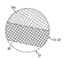
도 1c는 신발(10)의 실시예에서 메시 복합물 패널(16)의 일부의 세부를 보여주는 도 1a에 지시된 영역의 확대도이다. 메시 재료층(28; 메시층)은 후술되는 방식으로 기판 재료층(27; 기판층)에 접착된다. 예시를 위해, 점선(30) 아래의 메시층(28) 부분은 기판층(27)을 더 노출시키도록 도 1c에서 제거하였다. 편의를 위해 그리고 지나친 세부에 의해 도면을 불명료하게 하는 것을 피하기 위해, 메시층(28)의 메시 재료는 여러 도면에서 대각 배향을 갖는 간단하고 비교적 조대한 격자 패턴으로서 도시되어 있다. 메시층(28)에 사용되는 실제 재료(그 일례는 아래에 제공됨)는 보다 복잡한 및/또는 미세한 직조 구조를 가질 수 있다. 스킨 재료 패널(36a)이 메시 재료층(28) 및 기판층(27)에 접착되어 스킨층을 형성한다. 아래에서 또한 보다 상세하게 논의되는 바와 같이, 스킨 재료층은 메시 재료의 윤곽에 대응하는 윤곽을 갖는 표면 텍스쳐를 제공하도록 메시층(28)의 메시 재료에 합치한다. 간소화를 위해, 스킨층에 수직인 이 합치 관점은 도면에서 메시층(28)에 사용된 격자 패턴의 부분 파선 버전으로서 나타낸다. 1C is an enlarged view of the area indicated in FIG. 1A showing details of a portion of the mesh
도 1a 및 도 1b를 참조하면, 기판층(27)의 기판 재료는 설포 개구(26), 측방향 통기 홀(31, 32), 중간 통기 홀(33), 및 상부 전족부 통기 홀(34)을 제외하고 메시 복합물 패널(16)의 전부를 가로질러 연장된다. 다른 실시예는 보다 많거나 적은 홀들, 및/또는 상이한 형태의 홀들을 및/또는 상이한 지점에 포함하는 내부 기판 재료층을 갖는다. 도 4a 내지 도 4l과 관련하여 아래에서 더 설명되는 바와 같이, 메시층(28)의 메시 재료는 도 1a 및 도 1b의 실시예에서 대부분의 패널(16)에 걸쳐서 기판층(27)에 접착되지만, 이는 다른 실시예들에서의 사례가 아닐 수 있다.1A and 1B, the substrate material of the
도 1a 및 도 1b의 실시예는 또한 패널(36a, 36b, 36c 및 36d)에 의해 형성되는 스킨층을 포함한다. 패널(36b, 36c)의 스킨 재료는 메시에 대응하는 표면 텍스쳐를 제공하도록 메시층(28)의 메시 재료에 유사하게 합치한다. 패널(36d) 아래에 있는 메시 재료는 아래에서 또한 보다 자세하게 설명되는 바와 같이 패널(36d)의 외측면 상에 매끄러운 텍스쳐를 제공하도록 압축된다. The embodiment of FIGS. 1A and 1B also includes a skin layer formed by
메시층(28)은 기판층(27)에 직접 접착되기 때문에, 메시와 기판 재료의 조합된 강도는 인장 강도를 제공하기 위한 갑피(11)의 외측면 상에 다른 재료의 필요성을 미연에 방지한다. 이는 다양한 종래의 신발 구성 기술을 이용하여 갑피(11)가 훨씬 더 가볍게 되는 것이 가능하게 한다. 스킨 재료의 패널들(비교적 경량임)은 마모 보호가 유용한 갑피의 특정 영역에 포함될 수 있다. Since the
기판층(27)의 통기 홀(31, 32, 33, 34)은 공기가 메시층(28)의 메시 재료의 천공부를 통해 유동하게 한다. 이 유동은 신발(10) 착용자의 발을 냉각 및 건조하는 데에 일조한다. 몇몇 실시예에서, 통기 홀(31, 32, 33, 34)들 중 하나 이상의 둘레의 구역에서 기판층(27)과 착용자의 발(또는 착용자의 양말 신은 발)을 분리시키는 추가 재료층들이 존재하지 않고, 공기가 신발(10)의 내부에 직접 도달할 수 있다. 다른 실시예에서, 신발(10)의 갑피(11)는 기판층(27)과 착용자의 발 사이에 추가 라이닝(예컨대, "부티(bootie)")을 포함할 수 있다. 그러한 실시예에서, 공기는 홀(31, 32, 33, 34)을 통해 착용자의 발에 직접 도달할 수 없지만, 부티 또는 기타 라이너에 사용된 재료가 기판층(27)에 사용된 재료보다 상당히 더 통기성이기 때문에, 통기는 종래의 많은 구성에 비해 여전히 향상된다. The vent holes 31, 32, 33, 34 of the
통기 홀의 개수, 크기 및 위치는 여러 실시예에서 변할 것이다. 몇몇 실시예에서, 갑피는 직경이 2 mm만큼 작은 통기 홀을 포함할 수 있지만, 다른 실시예에서, 통기 홀은 매우 커서 갑피의 실질 부분을 덮을 수 있다. 몇몇 실시예에서, 여러 개의 통기 홀들 간의 최소 간격은 특정한 실시예에 사용되는 메시층 재료와 기판층 재료를 효율적으로 접착하는 데에 필요한 최소 영역을 기초로 할 수 있다.The number, size and location of the vent holes will vary in various embodiments. In some embodiments, the upper may include a venting hole as small as 2 mm in diameter, but in other embodiments, the venting hole may be very large to cover a substantial portion of the upper. In some embodiments, the minimum spacing between multiple vent holes may be based on the minimum area required to efficiently bond the substrate layer material to the mesh layer material used in a particular embodiment.
스킨 층 패널(36a, 36b, 36c, 36d)의 재료는 메시층(28)에 대해 마모 보호를 제공한다. 스킨 재료 패널은 또한 장식 목적을 위해 추가될 수 있다. 예컨대, 스킨 재료 요소는 로고 형태의 요소(36d) 또는 신발(10)의 제조업자의 기타 식별자 등의 하나 이상의 추가 요소를 포함할 수 있다. 스킨층 패널(36a-36d)의 대부분은 메시층(28)의 메시 재료 상에 중첩되지만, 스킨층 패널들 중 일부는 메시 재료의 개재층 없이 기판층(27)에 직접 접착될 수 있다. 예컨대, 도 4a-4l과 관련하여 아래에서 보다 상세히 설명되는 바와 같이, 스킨층 패널(36a-36d)은 메시층(28)이 연장되지 않는 기판층(27)의 일부를 덮는다. 더욱이, 또한 아래에서 보다 상세히 설명되는 바와 같이, 스킨층 패널(36a)의 일부는 뒤보강 패널(17)과 중첩하여 그 뒤보강 패널에 접착된다. 몇몇의 경우에, 개재하는 메시층은 구조적 목적을 위해 생략된다. 개재 메시층은 또한 장식을 이유로 생략될 수 있다. The material of the
신발(10)은 발포형 복사뼈 칼라(141), 뒤축(도시 생략) 및 설포(41)를 포함한다. 설포(41)는 갑피(11)의 내측에 재봉되거나 달리 접착될 수 있다. 칼라(141)의 부착은 후술된다. 갑피(11)는 임의의 다양한 방식으로 중창(42)에 접착될 수 있다. 몇몇 실시예에서, 갑피(11)는 슬립 라스팅(slip lasting)되고 스트로벨층(Strobel layer)에 부착되는데, 이어서 스트로벨층은 중창(42)의 상부면에 접착된다. 다른 실시예에서, 다른 타입의 구성이 중창 또는 다른 밑창 구성요소에 갑피(11)를 부착시키도록 사용된다. The
도 1a 및 도 1b에서 알 수 있는 바와 같이, 메시층(28)의 메시 재료(조대한 대각선 격자로서 도 1a 내지 도 1c에 나타냄)는 복합물 패널(16)의 실질 부분에 걸쳐서 노출된다. 구체적으로, 해당 메시 재료는 스킨층 패널(36a-36d)들 중 하나에 의해 덮이지 않는 패널(16)의 구역에서 직접 볼 수 있다. 그러나, 스킨층 패널에 의해 덮인 영역들의 대부분에서, 아래에 있는 메시 재료의 패턴은 메시에 대한 스킨층의 합치성 때문에 여전히 보인다. 몇몇 실시예에서, 메시층에서 메시 재료의 패턴은 완성된 신발의 메시 복합물 패널의 표면의 실질 부분(또는 심지어 대부분)에 걸쳐 보인다. 이 패턴은 메시가 노출되는 영역[예컨대, 개구(31, 32, 33, 34) 위 및 이들 개구 둘레의 구역]에서 또는 스킨층 패널의 윤곽[예컨대, 도 1c에 도시된 패널(36a)의 부분]으로서 직접 보일 수 있다. 몇몇 실시예에서, 노출된 메시의 비율은 신발의 목적에 따라 좌우될 것이다. 1A and 1B, the mesh material of the mesh layer 28 (shown in FIGS. 1A-1C as a coarse diagonal mesh) is exposed over a substantial portion of the
도 1a 및 도 1b의 신발(10)은 특정한 실시예에 따른 다층 접착식 메시 복합물 갑피 패널을 갖는 신발의 단순한 일례이다. 추가 실시예는 다른 스타일의 신발들, 상이한 타입의 중창/겉창 조합을 갖는 신발들, 상이한 패턴의 기판 재료 홀들을 갖는 신발들, 및 상이한 스킨 재료 구성을 갖는 신발들을 포함한다. 또 다른 실시예는 추가의 층들 및/또는 추가 타입의 재료의 층들을 갖는 신발을 포함한다.The
도 2는 다층 접착식 메시 복합물 패널(16)의 생성을 보여주는 부분 개략도이다. 기판층(27), 메시층(28) 및 스킨층 패널(36a-36d)은 후술되는 방식으로 조립된다. 설명을 위해, 기판층(27)은 미세한 스티플링(stippling)에 의한 단면도로 도시되고, 스킨 패널은 조대한 스티플링에 의해 도시되며, 메시층(28)은 크로스 해칭에 의해 도시되어 있다. 메시층(28)의 크로스 해칭된 부분들 사이의 개방 영역은 메시 재료 개구에 대응한다. 메시층(28)과 기판층(27) 사이에는 고온 용융 접착 재료(작은 흑점으로 도시됨)의 층(39)이 개재되어 있다. 메시층(28)과 스킨층 패널(36a-36d) 사이에 고온 용융 접착 재료의 다른 층(40)이 배치되어 있다. 층들이 함께 가봉된 후에, 조립체는 열 도전성 실리콘 패드(44)에 의해 피복되고 스킨 재료 패널들이 실리콘 패드(44)와 대면한 상태로 가열된 프레스(45) 내에 놓인다. 이어서, 접착 재료를 활성화시키고 스킨 재료를 그 용융점에 도달시키도록 열 및 압력이 인가된다. 그 결과, 층(39, 40)의 접착 재료는 기판층(27)을 메시층(28)에 접착시키고 메시층(28)을 스킨층 패널(36a-36d)에 접착시키며, 패널(36a-36d)의 스킨 재료는 층(28)의 메시 재료에 합치하기(더 나아가서 접착하기) 시작하여, 여러 층들이 단일체 패널이 되도록 접착된다. 열간 프레싱 후에, 층들은 별개의 냉각 프레스(도시 생략) 내에서 다시 프레싱된다. 프레싱 작동의 추가 상세 설명은 아래에서 제공된다.2 is a partial schematic diagram showing the creation of a multi-layered adhesive mesh
몇몇 실시예에서, 고온 용융 접착 재료의 별개의 패널은 스킨층 패널과 메시 또는 기판층 패널 사이에 위치되지 않을 수 있다. 대신에, 스킨층 패널은 스킨층을 하나 이상의 다른 층에 융합시키도록 스킨층 패널의 용융을 통해서만 다른 층(들)에 접착된다. 유사하게, 기판 재료 패널과 메시 재료 패널 사이에 고온 용융 접착 재료의 별개의 패널을 삽입하는 것은 몇몇 실시예에서 불필요하다. 특정한 실시예에서, 예컨대, 기판층(27)은 제1 재료층(예컨대, 인공 가죽)과, 기판 재료 제조업자에 의해 제1 재료층의 면에 미리 적층되는 제2 재료층(예컨대, 열가소성 폴리우레탄)을 포함하는 적층체를 포함할 수 있다. 이어서, 2개의 층의 기판 재료의 패널은 신발 제조업자에 의해 형상에 맞게 절단되어 기판층(27)으로서 사용될 수 있다. 그러한 실시예에서, 제2 재료층은 메시층(28)과 대면하도록 배향되고 메시층(28)(그리고 스킨층(들))에 융합하도록 프레싱 중에 용융하여, 별개의 접착 재료층(39)이 생략될 수 있다. 사실상, 몇몇 실시예는 임의의 별개의 접착 재료층을 필요로 하지 않고, 접착을 달성하기 위하여 스킨층 및/또는 기판층 자체의 용융에 의존하지 않을 수 있다. 다른 별법으로서, 메시, 기판 또는 스킨 재료의 큰 섹션들은 큰 재료 섹션들로부터 개별적인 갑피 패널들을 절단하기 전에 (예컨대, 재료 공급업자에 의해 또는 신발 제조업자에 의한 예처리 단계에서) 미리 부착된 별개의 고온 용융 접착 재료[예컨대, 층(39 또는 40)에 사용되는 것과 같음]를 가질 수 있다. 이들 기술의 조합이 또한 사용될 수 있다. In some embodiments, a separate panel of the hot melt adhesive material may not be positioned between the skin layer panel and the mesh or substrate layer panel. Instead, the skin layer panel is bonded to the other layer (s) only by melting the skin layer panel to fuse the skin layer to one or more other layers. Similarly, inserting a separate panel of hot melt adhesive material between the substrate material panel and the mesh material panel is unnecessary in some embodiments. In a particular embodiment, for example, the
도 3은 고온 및 저온 프레싱 후에 메시 복합물 패널(16)의 구조를 보여주는, 도 1a에 지시된 위로부터의 부분적인 개략 단면도이다. 예시를 위해, 도 3에서 3개의 상이한 구역들을 분류한다. 구역 A는 기판층(27)의 홀(32)이 배치되는 메시 복합물 패널(16)의 위치에 대응한다. 구역 A에는 다른 재료층이 존재하지 않기 때문에, 메시층(28)의 메시 재료는 이 구역에서 다른 재료에 접착되지 않는다. 갑피(11)가 점선에 의해 도 3에 도시된 바와 같은 라이너[즉, 기판층(27)의 내측 상에]를 포함한다면, 메시층(28)의 메시 재료는 적어도 몇몇 실시예에서 기판층(27)의 홀의 구역에 있는 라이너에 접착되지 않는다. 그러나, 몇몇 실시예에서, 라이너는 메시층(28) 및/또는 몇몇 위치에서 쉘(11)의 다른 부분에 재봉되고 및/또는 몇몇 위치에서 기판층(27)의 내측면에 접착될 수 있다. FIG. 3 is a partial schematic cross-sectional view from above indicated in FIG. 1A, showing the structure of the mesh
도 3의 구역 B는 스킨 재료 패널이 존재하지 않는 메시 복합물 패널(16)의 위치에 대응한다. 구역 C는 기판층(27), 메시층(28) 및 스킨층 패널 요소(36a)가 존재하는 위치에 대응한다. 구역 B와 C에서, 그리고 메시 복합물 패널(16)에 걸쳐서, 기판층(27)의 기판 재료와 메시층(28)의 메시 재료는 이들 2개의 재료가 접촉하는 모든 표면에서 함께 접착된다. 유사하게, 스킨층 요소(36a)와 기판층(27)의 기판 재료는 이들 재료들이 패널(36a) 및 메시층(28)의 메시 재료와 같이 접촉하는 모든 표면에서 함께 접착된다. 다른 스킨 재료 패널이 유사하게 기판층(27)의 기판 재료와 메시층(28)의 메시 재료에 접착된다. 기판과 메시 재료들, 및/또는 스킨 재료들의 접착은 재료들을 함께 효율적으로 융합시켜 개별적인 성분보다 강한 재료를 생성한다. Area B in Fig. 3 corresponds to the location of the mesh
구역 C에서 또한 알 수 있는 바와 같이, 패널(36a)의 스킨 재료는 메시 재료 패턴의 윤곽이 패널(36a)을 통해 드러나도록 메시층(28)의 메시 재료에 합치한다. 메시층(28) 위에 놓이는 기타 스킨 재료 패널은 유사하게 메시 재료에 합치한다. 이 방식에서, 갑피(11)는 달리 가능할 수 있는 것보다 더 연속적인 외양을 가질 수 있다. 아래에 있는 메시 재료를 보이게 하는 텍스쳐를 갖는 스킨 재료의 층을 제공함으로써, 신발(10)의 잠재적인 구매자가 또한 신발(10)의 구조를 알게 된다. 더욱이, 스킨 재료의 그 아래의 메시층 및 기판층 재료들 사이의 접촉의 등각 특질은 접착된 표면적과 전체 재료 강도를 증가시키는 데에 일조한다. As can also be seen in Zone C, the skin material of
전술한 바와 같이, 기판층(27)의 기판 재료는 신발(10) 착용자의 발에 대해 지지 및 보호를 제공한다. 적어도 몇몇 실시예에서, 기판 재료는 합성 가죽 또는 갑피가 외부 물체와 접촉하게 되는 구역 및/또는 발 지지가 요구되는 구역에서 발을 보호하는 데에 충분한 내구성을 갖지만 편안함을 제공하도록 충분히 가요성을 갖는 다른 재료이다(또는 포함한다). As described above, the substrate material of the
많은 상이한 기판 재료가 사용될 수 있다. 몇몇 실시예에서, 기판 재료는 적층 패키지(즉, 갑피를 생성하도록 조립되는 기판, 메시 및 기타 재료들의 적층체)에 대한 지지부를 제공하고 메시 재료에 적절하게 접착하도록 선택된다. 그러한 목적을 달성하기 위하여, 기판 재료는 제한된 신축성을 갖고, 양호하게 접착하며, TPU 고온 용융물과 화학적으로 융화하고, 연속적인(즉, 비메시) 표면을 가져서 더 큰 접착 표면적을 제공하며, 대량 생산시에 선명한 에지를 갖게 절단될 수 있도록 선택될 수 있다. 표 1은 적어도 몇몇 실시예에서 사용될 수 있는 기판 재료의 예를 열거한다. 다른 재료들도 또한 사용될 수 있다.Many different substrate materials can be used. In some embodiments, the substrate material is selected to provide support for a laminate package (i.e., a laminate of substrates, meshes, and other materials that are assembled to create an upper) and to properly adhere to the mesh material. In order to achieve such a purpose, the substrate material has a limited stretchability, adheres well, chemically compatibilizes with the TPU hot melt, has a continuous (i.e., non-mesh) surface to provide a larger adhesive surface area, Can be selected so as to have a sharp edge at the time. Table 1 lists examples of substrate materials that may be used in at least some embodiments. Other materials may also be used.
층(28)의 메시 재료는 2개의 재료가 접착되는 기판 재료의 강도를 증대시킴으로써 갑피(11)를 보강하여 보다 얇은 기판 재료 요소들의 사용을 허용한다. 갑피에 대한 메시 재료의 통합은 또한 기판 재료의 완전 보호 및 지지가 중요하게 되지 않는 영역에서 기판 재료의 제거를 허용하여, 기판 재료 및 전체 신발 중량의 추가 감소를 가능하게 한다. 층(28)의 메시 재료는 또한 공기가 기판층(27)의 개구를 통해 유동하게 하여 착용자의 발을 냉각 및 건조하는 데에 일조하게 한다. The mesh material of
적어도 몇몇 실시예에서, 층(28)의 메시 재료는 개방 구조를 갖는 단일층의 경편(warped knit)(또는 다른 타입의 직조 재료)이고 나일론, 폴리에스터, 나일론/폴리에스터 혼방, 재생된 폴리에틸렌 테레프탈레이트(rePET), 또는 기타 재료로 형성된다. 특정한 실시예에서, 메시 재료는 50%를 넘는 개방 영역을 갖는다(예컨대, 50%를 넘는 재료 표면적은 공기가 한 면에서 다른 면으로 자유롭게 유동할 수 있는 개방 공간을 포함한다). 몇몇 실시예에서, SPANDEX(또는 기타 신축성 메시) 및 스페이서 메시(필러 얀(filler yarn)을 갖는 메시)는 바람직하지 않다. 표 2는 적어도 몇몇 실시예에서 메시 재료의 예들을 열거한다. 다른 재료들도 또한 사용될 수 있다.In at least some embodiments, the mesh material of
패널(36a-36d)용 스킨 재료는 메시와 기판 재료를 보강하고, 특정 영역에서 메시 재료층을 보호하며, 및/또는 갑피(11)에 장식면을 제공한다. 적어도 몇몇 실시예에서, 스킨 재료는 열가소성 폴리우레탄(TPU) 또는 기타 적절한 재료이다. 특정한 실시예에서, 스킨 재료는 내마모성을 위한 내열 외부층과 고온 용융 접착을 위한 내부층을 갖는 다층 재료이다. 예컨대, 외부층은 열경화성 폴리우레탄(PU) 또는 높은 용융 온도를 갖는 TPU일 수 있고 내부층은 고온 용융 접착 및 제조 온도에 적합한 보다 낮은 용융 온도를 갖는 TPU일 수 있다. 표 3은 적어도 몇몇 실시예에서 스킨 재료에 사용될 수 있는 재료들의 예를 열거한다. 다른 재료들도 사용될 수 있다.The skin material for
적어도 몇몇 실시예에서, 그리고 도 2에 개략적으로 도시된 바와 같이, 다양한 재료층들은 이들 재료들 사이에 고온 용융 접착 재료의 분리층을 개재하고 가열된 프레스로 그 접착 재료를 활성화시킴으로써 접착된다. 적어도 몇몇 실시예에서, 고온 용융 접착 재료는 일반적으로 미세한 스파이더 웹과 두께(및 외양)가 유사한 미세한 섬유질 매트의 사전 활성화 일관성을 갖는다. 이는 활성화된 접착 재료가 경화된 접착 재료를 과도하게 생성시키는 일 없이 접촉면을 완전히 덮게 한다. 몇몇 실시예에서, 고온 용융 접착 재료 매트는 메시와 스킨 재료의 시트들 상에 놓일 수 있고, 이때에 시트는 롤링된 상태로 신발 제조업자에게 제공된다. 제조업자는 메시와 접착 재료 결합체(또는 스킨과 접착 재료 결합체)를 푼 다음 단일의 다이 절단 공정으로 갑피를 위한 적절한 형태를 절단할 수 있다. In at least some embodiments and as shown schematically in Figure 2, the various material layers are bonded between these materials by interposing a separate layer of hot melt adhesive material and activating the adhesive material with the heated press. In at least some embodiments, the hot melt adhesive material generally has a prior activation consistency of a fine fibrous mat that is similar in thickness (and appearance) to a fine spider web. This completely covers the contact surface without causing the activated adhesive material to over-create the cured adhesive material. In some embodiments, the hot melt adhesive material mat may be placed on sheets of mesh and skin material, wherein the sheet is provided to the shoe manufacturer in a rolled state. The manufacturer can unfasten the mesh and adhesive material combination (or skin and adhesive combination) and cut the appropriate shape for the upper with a single die cutting process.
적어도 몇몇 실시예에서, TPU 고온 용융 접착 재료는 80℃ 내지 대략 120℃의 용융 온도를 가질 수 있고 폴리에스터 기반일 수 있다. 표 4는 적어도 몇몇 실시예에서 사용될 수 있는 고온 용융 접착 재료의 예를 열거한다. 다른 고온 용융 접착 재료도 사용될 수 있다. In at least some embodiments, the TPU hot melt adhesive material may have a melt temperature of from 80 캜 to about 120 캜 and may be polyester-based. Table 4 lists examples of hot melt adhesive materials that may be used in at least some embodiments. Other hot melt adhesive materials may also be used.
표 4의 최종 재료(폴리에테르 필름)가, 예컨대 높은 습도가 관심사인 특정한 실시예에서 바람직할 수 있다.
The final material (polyether film) of Table 4 may be desirable in certain embodiments, e.g., where high humidity is a concern.
메시 복합물 부분을 갖는 갑피 쉘의 제조Fabrication of Upper Shell with Mesh Composite Portion
적어도 몇몇 실시예에 따르면, 갑피의 접착식 메시 복합물 패널은 평탄한 형태의 다양한 층들을 위한 재료의 개별적인 패널들을 조립함으로써 생성된다. 갑피가 추가 부분[예컨대, 신발(10)의 패널(17) 등의 후방부]을 포함하는 것이라면, 추가 재료 요소가 조립 프로세스의 일부로서 포함될 수 있다. 패널 및 기타 요소들은 패널들과 요소들의 상대 위치가 이들 패널과 요소들이 완성된 신발에서 갖게 되는 위치에 대응하는 배열을 갖도록 조립된다. 개별적인 패널들 및/또는 기타 요소들을 적절한 배열로 조립하고 여러 위치에서 조립체를 시침(tacking)한 후에, 조립체는 조립된 요소들을 접착시키도록 일련의 프레싱 공정을 받는다. 이들 공정은 완성된 갑피에 포함될 많은 또는 모든 요소들을 포함할 수 있는 평탄한 일체형 유니바디 갑피 쉘을 생성한다. 이어서, 유니바디 갑피 쉘의 에지는 추가 마무리 및 중창에 대한 부착을 위해 준비가 된 3차원 갑피 본체를 생성하도록 결합될 수 있다. According to at least some embodiments, the upper, adhesive mesh composite panels are produced by assembling individual panels of material for the various layers in a flat form. Additional material elements may be included as part of the assembly process if the upper portion includes an additional portion (e.g., the rear portion of the
도 4a 내지 도 4l은 도 1a 및 도 1b의 신발(10)을 위한 메시 복합물 패널(16)을 제조하는 적어도 몇몇 실시예에 따른 프로세스를 도시하고 있다. 도 4a 및 도 4l에 도시된 단계 1에서, 뒤보강 패널(17)이 조립체 지그(100)에 부착된다. 도 4l은 도 4a에 언급된 위치로부터 지그(100)의 사용을 추가 도시하도록 포함되는 지그(100)와 뒤보강 패널(17)의 측면도이다. 지그(100)에서의 각 핀(101a-101q)은 상방으로 연장되고 하나 이상의 갑피 요소들을 위치 결정하도록 사용된다. 예컨대, 패널(17)에 대해 도시된 바와 같이, 핀(101a, 101b, 101e)은 뒤보강 패널(17)에서의 홀(102a, 102b, 102e)에 대응한다. 패널(17)은 핀(101a, 101b, 101e) 위에 홀(102a, 102b, 102e)을 각각 위치시키고 패널(17)을 지그(100) 상으로 압박함으로써 지그(100) 상에 위치 결정된다. 단계 1의 완료시에 상방을 향하는 뒤보강 패널(17)의 면은 외측을 향하고 완성된 신발(10)의 내부의 반대쪽이다. 패널(17)의 홀(102a)은 패널(17)이 에지(98)로부터 멀리 연장되는 작은 연장 탭(99)이다. 연장 탭(99)(및 기타 요소들 상에 유사한 연장 탭)은 나중의 제조 단계 중에 트리밍 가공된다. Figures 4A-4L illustrate a process according to at least some embodiments for making a mesh
갑피(11)의 기타 요소들은 유사한 방식으로 지그(100) 상에 위치 결정된다. 단계 2(도 4b)에서, 예컨대 고온 용융 접착 재료의 패널(53)이 뒤보강 패널(17)에 인접하게 위치된다. 접착 재료 패널(53)은 메시 복합물 패널(16)의 기판층(27)이 되는 기판 재료의 패널에 뒤보강 패널(17)을 접착시키도록 사용된다. 다른 실시예에서, 뒤보강 패널(17)은 갑피 쉘을 구성하는 상이한 방식으로[예컨대, 뒤보강 패널(17)의 적층된 층의 용융에 의존함으로써, 솔질한 액체 접착제를 이용함으로써] 및/또는 상이한 단계에서 부착될 수 있다. Other elements of the upper 11 are positioned on the
단계 3(도 4c)에서, 기판층(27)을 위한 재료 패널은 기판 재료 패널의 홀(104b 내지 104q)을 핀(101b 내지 101q) 위에 각각 압박함으로써 조립체 지그(100)에 부착된다. 홀(104b-104d, 104f 및 104q)은 후속하는 제조 단계에서 트리밍 가공된 연장 탭에 포함된다. 도 4c에서 보이는 바와 같이, 층(27)의 패널은 갑피(1)의 상부 전족부 구역에 결국 배치될 개구(34)를 포함한다(도 1a 및 도 1b 참조). 또한, 도 4c에서 보이는 바와 같이, 개구(31, 32)는 갑피(11)에서 결국 측방향으로 배치되고(도 1a), 개구(33)는 갑피(11)에서 결국 중간에 배치될 것이다. 몇몇 실시예에서, 홀(31, 32, 33, 34)은 기판층 패널이 큰 재료 피스로부터 다이 절단될 때에 절삭된다. 설포 개구(26; 도 1a 및 도 1b)는 조립 및 프레싱 후에 절삭될 것이다. 기타 실시예에서, 설포 개구(26)는 또한 기판 재료 패널이 다이 절단될 때에 기판 재료 패널로부터 절삭될 수 있다. 단계 3의 완료시에 노출되는 층(27) 패널의 측면은 외측을 향하고 완성된 신발(10)의 내부의 반대쪽에 있다.In step 3 (Figure 4c), a material panel for the
단계 4(도 4d)에서, 핀(101g, 101h, 101i, 101o) 위에 홀(108g, 108h, 108i, 108o)을 각각 압박함으로써 지그(100)에 대해 아이스테이 보강부(56)가 부착된다. 아이스테이 보강부(57)는 홀(101j, 101k, 101l) 위에 홀(109j, 109k, 109l)을 압박함으로써 유사하게 부착된다. 적어도 몇몇 실시예에서, 보강부(56, 57)는 신발끈 구멍을 위한 보강된 위치를 제공하도록 추가된다. 다른 실시예에서, 아이스테이 보강부는 생략되거나 상이한 형태를 가질 수 있다. 비활성화된 고온 용융 접착 재료의 패널이 또한 보강부(56, 57)와 기판층(27) 사이에 개재될 수 있다. In step 4 (Fig. 4D), the eye
다른 타입의 보강부가 아이스테이 보강부(56, 57)에 대해 사용된 것과 유사한 방식으로 신발 갑피의 다른 영역에 위치될 수 있다. 몇몇 실시예에서, 예컨대 추가 보강부가 완성된 갑피의 선부 구역에 배치될 기판층 패널의 영역에 걸쳐 위치될 수 있다. 다른 실시예에서, 보강 재료는 완성된 신발의 측방향 및 중간 측면에 배치되는 기판층 패널의 부분에 걸쳐 위치될 수 있고, 이들 보강 재료는 완성된 갑피에서 보강 스트랩 부착점을 형성한다.Other types of reinforcement may be located in different areas of the shoe upper in a manner similar to that used for the
단계 5(도 4e)에서, 핀(101b, 101c, 101d, 101e, 101p, 101q) 위에 홀(119b, 119c, 119d, 119e, 119p, 119q)를 각각 압박함으로써 층(28)을 형성하는 메시 재료의 패널이 지그(100)에 부착된다. 그러나, 홀(119b-119d, 119p)은 후속하는 제조 단계에서 트리밍 가공될 연장 탭에 포함된다. 단계 5의 완료시에 노출되는 층(28) 메시 재료 패널의 면은 외측을 향하고 완성된 신발(10)의 내부의 반대쪽에 있다. 활성화되지 않은 고온 용융 접착 재료의 층은 메시층(28) 패널과 기판층(27) 패널 사이에 포함된다. 몇몇 실시예에서, 층(28)의 패널을 위해 사용된 메시 재료의 롤은 공급업자로부터 고온 용융 접착 재료의 층이 일면에 미리 부착된 상태로 입수된다. 그러한 실시예에서, 층(28) 메시 재료 패널과 동일한 형태를 갖는 고온 용융 접착 재료의 분리층이 단계 1의 종결시에 기판층(27) 위에 위치되고, 평탄한 메시 재료 패널만이 단계 5에서 추가된다. 또 다른 실시예에서, 패널(27, 28) 사이의 고온 용융 접착 재료의 분리 패널은 TPU 등의 용융 가능한 재료로부터 형성된 미리 적층된 층을 갖는 기판 재료의 사용을 통해 미연에 방지된다. In step 5 (FIG. 4E), the mesh material (not shown) forming the
도 4e에서 보이는 바와 같이, 메시층(28) 패널은 기판층(27) 패널을 완벽하게 덮지 못한다. 예컨대, [완성된 신발(10)에서 갑피의 선부 및 측면 전족부 구역에 대응하는] 기판 재료 패널의 구역(110)은 메시 재료 패널에 의해 오버랩되지 않는다. 이 방식에서, 갑피(11)의 평활한 표면이 앞보강 또는 기타 외측 요부에 나중에 접착하도록 제공될 수 있다. 기판층(27)의 구역(111)은 기판층과 보강부(56, 57) 사이에 평활한 계면을 제공하도록 유사하게 메시 재료에 의해 덮이지 않는다. 스킨 재료에 사용된 재료와 달리, 보강부(56, 57)는 프레싱 프로세스에서 사용된 온도에서 메시층(28)에 손쉽게 합치하지 않는 보다 두꺼운 재료(예컨대, 나일론)으로부터 형성된다. 기판층(27)의 구역(112)은 아래에 있는 메시 재료층을 보이게 하지 않는 방식으로 스킨 재료 패널(36d)에 의해 나중에 덮이게 될 구역에 대응하고, 메시층(28)은 메시 재료의 추가된 강도가 구역(112)이 완성된 신발(10)에서 대응하는 갑피(11) 부분에 존재할 수 있도록 구역(112)을 덮는다. As shown in FIG. 4E, the
단계 6(도 4f)에서, 스킨 재료 패널(36c)이 핀(101c, 101d, 101f, 101j, 101p) 위에 홀(114c, 114d, 114f, 114j, 114p)을 각각 압박함으로써 지그(100)에 부착된다. 홀(114c, 114d, 114f, 114p)은 후속하는 제조 단계에서 트리밍 가공될 연장 탭에 포함된다. 패널(36c)은, 예컨대 완성된 신발(10)에서 선부, 중간 전족부 및 측방향 전족부 구역을 덮는 스킨 재료를 형성한다. 단계 6의 완료시에 노출되는 패널(36c)의 측면은 외측을 향하고 완성된 신발(10)의 내부의 반대쪽에 있다. 몇몇 실시예에서, 패널(36c) 및/또는 스킨 재료 패널에 사용된 재료의 롤은 또한 비활성화된 고온 용융 접착 재료의 층이 일면에 미리 부착된 상태로 공급업자로부터 입수된다. 다른 실시예에서, 스킨 재료 패널(36c)과 동일한 형태를 갖는 고온 용융 접착 재료의 분리층은 스킨 재료 패널(36c)과 단계 6의 일부로서 미리 위치된 층들 사이에 위치된다. 또 다른 실시예에서, 하나 이상의 스킨 재료 패널은 고온 프레싱 공정(후술됨) 중에 스킨 재료의 용융 및 냉각 중에 후속하는 고형화에 의해 다른 층에 접착되고, 별개의 접착 재료가 이들 스킨 재료와 기타 내측을 향해 배치된 층들 사이에 개재되지 않는다. 도 4e와 도 4f를 비교하여 알 수 있는 바와 같이, 스킨 재료 패널(36c)은 메시 재료가 존재하지 않는 구역(110)에서 기판층(27) 위에 배치되도록 조립된다. The
몇몇 실시예에서, 여분의 및/또는 보다 높은 강도의 접착 재료 및/또는 추가 접착제가 완성된 신발의 갑피의 선부 구역 및/또는 기타 전방 구역들에 대응하는 복합물 패널의 부분에 포함될 수 있다. 이 추가 접착은 갑피의 선부가 여러 제조 공정(예컨대, 선부 형성, 라스팅(lasting) 가공) 중에 상당한 응력을 받을 수 있는 실시예에서 바람직할 수 있다. In some embodiments, extra and / or higher strength adhesive materials and / or additional adhesives may be included in the portion of the composite panel corresponding to the anterior region and / or other forward regions of the finished shoe. This additional adhesion may be desirable in embodiments where the top portion of the upper is subject to considerable stresses during various manufacturing processes (e.g., forming, pre-forming, or lasting).
단계 7(도 4g)에서, 스킨 재료 패널(36b)은 핀(101g, 101h, 101i, 101j, 101k, 101l, 101n, 101o) 위에 홀(113g, 113h, 113i, 113j, 113k, 113l, 113n, 113o)을 각각 압박함으로써 지그(100)에 부착된다. 패널(36b)의 외부 에지는 완성된 신발(10)의 내부의 반대쪽에 있고, 패널(36b)의 나머지(아래에 있는 기판 재료 패널과 메시 재료 패널의 부분과 함께)는 설포 개구(26)를 생성하도록 제거될 것이다. 단계 6의 패널(36c)과 같이, 패널(36b)은 외부면이 위를 향한 상태로 지그(100) 상에 위치되고, 패널(36b)과 아래의 요소들 사이에 고온 용융 접착 재료의 층이 개재된다. In step 7 (Fig. 4G), the
스킨층 재료의 패널(36a)은 핀(101a, 101b, 101e, 101m, 101n, 101o) 위에 홀(115a, 115b, 115e, 115m, 115n, 115o)을 각각 압박함으로써 단계 8에서 지그(100) 상에 위치된다. 홀(115a, 115b, 115b)은 후속하는 제조 단계에서 트리밍 가공될 연장 탭에 포함된다. 패널(36a)은 완성된 신발(10)에서 측방향 중족부와 후족부 구역의 부분들을 덮는 스킨 재료층을 형성한다. 단계 6에서 패널(36c)과 같이, 고온 용융 접착 재료의 층은 패널(36a)과 아래의 요소들 사이에 개재될 수 있다. 단계 8의 종결시의 결과는 뒤보강 패널(17)에 접착된 메시 복합물 패널(16)을 포함하는 갑피 쉘이 결국 되는 갑피 요소들의 패널 조립체이다. The skin
단계 9(도 4i)에서, 조립체(116)의 요소들은 고온 용융 접착 재료층들을 격리된 지점에서 부분적으로 활성화시킴으로써 함께 시침된다. 이 부분 활성화는 몇몇 실시예에서 고주파(HF; high frequency) 용접을 이용하여 수행될 수 있다. 예시를 위해, 결과적인 시침이 메시 복합물 패널을 형성하는 조립된 요소들의 표면 위에 분포되는 일련의 도트로서 도 4i에 개략적으로 도시되어 있다. 사실상, 시침 목적을 위해 열이 인가되는 실제 위치는 변할 수 있다. 단계 9에서 시침 용접은 휴대용 열풍기를 이용하여, 또는 핀(101a 내지 101q)을 수용하도록 구성된 플레이트를 갖는 프레스 내로 조립체(116)와 함께 지그(100)를 간단히 삽입시킴으로써 수행될 수 있다. 적어도 그러한 몇몇 실시예에서, 시침 단계를 위한 프레스 상태는 선택된 특정한 고온 용융물에 따라 좌우되지만, 통상적으로 온도는 약 115℃ 내지 약 125℃이고, 대략 30 내지 35초 동안 대략 2 내지 6 kg/cm2의 표면 압력으로 프레싱한다. In step 9 (FIG. 4I), the elements of
단계 9의 시침은 조립체(116)의 개별 요소들이 조립체(116)가 지그(100)로부터 제거될 때에 조립된 상태로 남아 있도록 부분 접착이 생기게 한다. 단계 10(도 4j)에서, 시침된 조립체(116)는 개별 요소들을 함께 완전히 접착시키도록 열간 프레싱된다. 구체적으로, 시침된 조립체(116)는 지그(100)로부터 제거되어 열 전달 실리콘 패드(120) 상에 위치된다. 조립체(116)는 단계 8과 9의 종결시에 상방을 향하는 면이 패드(120)쪽으로 아래를 향해 위치 결정되도록 뒤집힌다. 이형지(121; release paper)가 조립체(116) 위에 위치된 후에, 가열된 압반(122, 123)이 결합되어 조립체(116)를 압축하도록 압력이 인가된다. 간소화를 위해, 이형지(121)의 외측 에지만이 도 4j에 도시되어 있다. 다른 실시예에서, 내측면이 하부 압반(122)을 향하도록 패널 조립체(116)가 배치될 수 있는데, 이형지(121)는 조립체(116)의 내측면과 압반(122) 사이에 삽입되고 패드(120)는 조립체(116)의 외측면과 상부 압반(123) 사이에 삽입된다. The hour hand of
적어도 몇몇 실시예에서, 실리콘 패드(120)는 단계 10의 프레싱 공정 전에 110℃로 먼저 예열된다. 단계 10의 열간 프레싱 공정을 위한 통상적인 프로세스 파라미터는 120℃의 상부 및 하부 프레스 압반 온도, 대략 20 kg/cm2의 프레스 압력, 및 30 내지 40초의 프레스 시간이다. 그러나, 특정한 신발 갑피를 위한 프로세스 파라미터는 갑피에 적용될 수 있는 재료들의 조합 및 패널 구조에 따라 좌우될 것이다. 몇몇 실시예에서, 단계 10의 프레스 시간은 특정한 갑피 설계를 위한 패널들을 시험 패널 조립체로 조립함으로써 결정될 수 있는데, 열전대 온도 프로브가 시험 패널 조립체 내에서 하나 이상의 지점에 삽입된다. 이어서, 시험 패널 조립체는 내부 조립체 온도가 시험 패널 조립체의 스킨 재료에 대해 원하는 용융점에 도달했다는 것을 온도 프로브가 지시할 때까지 120℃ 프레스 압반들 사이에서 프레싱된다. 원한다면, 프레스 시간은 프레스 압반 온도를 조정함으로써 그 이상으로 또는 그 이하로 조정될 수 있다. 특정한 스킨 재료에 대해 원하는 용융점 온도는 스킨 재료에 대한 최대 열전달과 관련된 온도를 찾기 위하여 시차 주사 열량계(주사율: 50℃/min)를 이용함으로써 결정될 수 있다. 프레스 압력은 하나 이상의 시험 패널 조립체의 층들 간의 접착이 불충분하면 그 이상으로 조정되거나 표면 요부들이 과도하게(그리고 바람직하지 않게) 평탄해지면 그 이하로 조정될 수 있다. In at least some embodiments, the
단계 10의 열간 프레싱 후에, 조립체(116)는 접착 프로세스를 계속하고 접착을 향상시키는 압력하에서 용융된 TPU가 설정될 수 있도록 실온의 프레스 압반들 사이에서 "냉간" 프레싱된다. 여기에 사용된 바와 같이, "실온"이란 대략 20℃ 내지 대략 30℃의 온도를 말한다. 단계 10의 열단 프레싱 직후에 조립체(116)를 냉간 프레싱함으로써, 개별 요소들은 고온 용융 접착 재료와 스킨층들이 고형화하는 동안에 접촉 상태로 유지됨으로써, 초기 열간 프레싱 후에 재료들이 서로 반발하는 것을 방지한다. 후속하는 냉간 프레싱이 없다면, 예컨대 적어도 몇몇 실시예에서 스킨층 요소는 스킨층의 외측면 상의 메시 패턴을 보여주도록 아래에 있는 메시층에 합치하지 못하게 될 것이다. After hot pressing of
도 4k는 단계 10 직후에 이어지는 단계 11의 냉간 프레싱을 보여준다. 조립체(116)를 열간 프레스 압반(122, 123; 도 4j)으로부터 제거하고 이형지(121)를 벗긴 후에, 조립체(116)는 냉간 압반(130, 131) 사이의 실리콘 패드(129) 상에 배치된다. 단계 10의 완료시에 패드(120)에 남아 있는 잔열(residual heat)을 피하기 위하여 단계 11에서 상이한 실리콘 패드가 사용될 수 있다. 단계 10에서 실리콘 패드(120)를 향한 조립체(116)의 동일한 면이 단계 11에서 실리콘 패드(129)를 향한다. 적어도 몇몇 실시예에서, 압반(130 및/또는 131)은 압반을 원하는 온도로 유지하기 위하여 내부 수위선 또는 다른 메카니즘을 포함할 수 있다. 이어서, 조립체(116)는 압반(130, 131) 사이에서 프레싱된다. 단계 11의 냉간 프레싱 공정을 위한 통상적인 프로세스 파라미터는 실온(예컨대, 25℃)의 상부 및 하부 프레스 압반, 대략 30kg/cm2의 프레스 압력, 및 대략 30초의 프레스 시간이다. 4k shows the cold pressing of
단계 10 및 11에서 사용된 열 도전성 실리콘 패드(120, 129)는 각각 적어도 부분적으로 압축될 수 있고 패널 조립체(116)의 표면 요부들에 합치될 수 있다. 이는 패널 조립체의 압축이 표면 요부들을 지나치게 평탄하게 하는 일없이 여러 층들을 접착시키게 한다. 이는 또한 스킨 재료가 아래에 있는 메시 재료의 층들에 합치하여 그 메시 재료의 윤곽을 드러내게 하는 도 3의 구역 C에 도시된 바와 같은 프로파일의 형성을 가능하게 한다. 적어도 몇몇 실시예에서, 각 실리콘 패드(120, 129)는 15 내지 30의 쇼어 A 경도와 대략 0.3 Watts의 열 도전성을 갖는다. 그러나, 상이한 열 도전성을 갖는 패드는 프레싱된 재료에서 원하는 내부 온도를 달성하도록 프레스 압반 온도를 조정함으로써 사용될 수 있다. The thermally
단계 11의 완료시에, 시침된 조립체(116)는 메시 복합물 패널(16)과 뒤보강 패널(17)을 포함하는 융합된 유니바디 쉘로 변형된다. 도 5a는 도 4a-4l의 단계 1 내지 11의 완료로부터 생기고 마무리 공정의 준비가 된 융합된 유니바디 갑피 쉘(116)을 도시하고 있다. 도 5a에서 에지(133, 134, 135)가 마킹되는데 아래에서 더 논의된다. 단계 12(도 5b)에서, 설포 개구(26)가 절삭되고, 복합물 패널(16)의 외부 에지 상의 연장 탭이 트리밍 가공되며, 신발끈 구멍이 펀칭된다. 단계 13(도 5c)에서, 스킨층 요소(36d)는 냉간 프레싱 단계없이 HF 용접과 조합된 열간 프레싱에 의해 부착되어, 스킨층 요소(36d)는 갑피(10)의 다른 부분과 상이한 텍스쳐를 갖게 된다. 구체적으로, 요소(36d)의 형태를 갖는 툴(도시 생략)이 패널(36d)이 배치될 위치에서 유니바디 갑피 쉘(116)에 적용된다. 이어서, HF 용접 열이 툴 아래에 있는 층(28)의 메시 재료의 구역을 평탄하게 하도록 상기 툴을 통해 인가된다. 요소(36d)는 사용시 재료에 적절한 온도, 압력 및 시간에서 원하는 용융물 패턴 형태의 가열 요소(예컨대, 구리, 황동, 알루미늄 또는 기타 도전성 재료로 형성됨)를 이용하여 적소에 용접되는 HF 및 고온 용융 접착 재료의 개재층을 갖는 평탄한 구역에 배치된다. 몇몇 실시예에서, 요소(36d)는 신발의 제조업자와 관련된 로고 또는 기타 표시의 형태일 수 있고, 요소(36d)를 위한 상이한 텍스쳐가 신발 갑피의 다른 부분으로부터 로고를 오프셋시키도록 또는 몇몇의 다른 심미적 목적을 위해 희망될 수 있다. 요소(36d)를 위한 상이한 텍스쳐를 원하지 않는 실시예에서, 스킨층 요소(36d)는 도 4a-4l의 프로세스 흐름에서 단계 5와 9 사이의 어딘가에 삽입되는 단계에서 추가된 다음, 갑피 유니바디 쉘(116)을 형성할 때에 기타 요소들과 함께 열간 프레싱 및 냉간 프레싱될 수 있다. At the completion of
단계 14(도 5d)에서, 칼라 요소(141)가 부착된 발포 요소(140)가 홀(152a 내지 152i)을 지그(151) 상의 대응하는 핀(153a 내지 153i) 위에 삽입시킴으로써 제2 지그(151) 상에 배치된다. 칼라 요소(141)는 발포 요소(140)의 상부 에지를 현수하는 립을 형성한다. 몇몇 실시예에서, 칼라 요소(141)는 전도된 "U" 단면을 갖는 재료의 접힌 섹션으로부터 형성될 수 있는데, 상기 "U"의 하나의 레그는 발포 요소(140)의 내측 상부 에지에 부착되고 다른 레그는 상기 상부 에지의 외측에서 발포 요소(140)를 현수한다. 발포 요소(140)용 재료는 개방 셀 PU 발포재를 포함할 수 있고, 칼라 요소(141)용 재료는 합성 스웨이드를 포함할 수 있다. 단계 15(도 5e)에서, 유니바디 갑피 쉘(116)의 에지(134; 도 5a 참조)는 칼라 요소(141)의 립 아래에 삽입된다. 단계 16(도 5f)에서, 칼라 요소(141)[또는 칼라 요소(141)의 일부]에 대응하는 형태를 갖는 구리 HF 용접 툴(도시 생략)이 칼라 요소(141) 상에 프레싱되고 (사용시 재료에 적절한 온도, 압력 및 시간으로) 열 인가됨으로써, 쉘(116), 발포 요소(140) 및 칼라 요소(141)를 HF 용접부(153)를 따라 접착시킨다.In step 14 (Fig. 5d), the foaming
단계 17(도 5g)에서, 에지(133, 135; 도 5a 참조)에 인접한 유니바디 갑피 쉘(116)의 구역은 3차원 갑피 형태로 쉘(116)을 변형시키도록 결합된다. 단계 17 전에, 칼라(141) 상의 연장 탭과 발포 요소(140)의 초과 부분이 트리밍 가공된다. 단계 17의 일부로서, 에지(135)를 포함하는 패널(16)의 부분은 에지(135)에 인접한 에지를 따라 패널(16)의 형태에 합치하고 쉘(116)을 적소에 유지하는 레일(161, 162)을 갖는 지그(160) 내로 배치된다. 이어서, [발포 요소(140)와 칼라 요소(141)가 부착된) 쉘(116)의 나머지는 에지(133)를 에지(135) 위에 배치하도록 지그(160)의 안쪽 아래와 둘레에서 래핑된다. 에지(133, 135)에 인접한 오버래핑된 부분에 대응하는 형태를 갖는 HF 용접 툴(예컨대, 구리 또는 기타 도전성 재료로부터 형성됨)은 접힌 패널(17) 상에 프레싱되고 (사용시 재료에 적절한 온도, 압력 및 시간으로) 열 인가됨으로써, HF 용접부(163)를 따라 에지(133, 135)에 인접한 쉘(116)의 구역들을 접착시킨다. In step 17 (Figure 5g), the area of the unibody
단계 17의 완료 후에, [칼라 요소(141)와 발포 요소(140)가 부착된] 3차원 쉘(116)은 중창(42; 도 1a 및 도 1b)에 접착하기 전에 추가 마무리를 받을 수 있다. 몇몇 실시예에서, 메시 복합물 패널(16)의 선부는 원하는 선부 구역 형태를 얻도록 가열되어 성형 형태로 부착된다. 몇몇 실시예에서, 3차원 쉘의 선부는 대략 20초 동안에 대략 80℃로 가열된다. 이어서, 가열된 선부는 적당한 선부 형태를 얻도록 성형 다이 상에 프레싱되는데, 이어서 대략 30초 동안 대략 -4℃에서 냉각 단계 중에 뱀프 개더링(vamp gathering)이 수행된다. 플라스틱 카운터가 뒤꿈치 구역에서 뒤보강 패널(17)과 발포 요소(140) 사이에 삽입되어 재봉되거나 달리 적소에 고착된다. 설포 및/또는 부티 또는 다른 타입의 라이너가 부착되고, 갑피(11)는 갑피가 구둣골 상에 있는 동안에 갑피 패널의 하부 에지 둘레의 적소에 스트로벨(Strobel)을 재봉함으로써 완성된다. After completion of
전술한 것과 유사한 공정이 쉘(116)에 부착하기 위한 설포를 생성하는 데에 사용될 수 있다. 구체적으로, 설포는 또한 하나 이상의 층을 지그 상에 위치 결정하고, 이들 층을 함께 시침한 다음, 이들 층을 열간 및 냉간 프레싱하여 설포 형태의 메시 복합물 패널을 형성함으로써 형성될 수 있다. A process similar to that described above can be used to create a sulfo for attaching to the
설포의 메시 복합물은 전술한 것(예컨대, 기판층, 메시층 및 스킨층)과 유사한 재료들 또는 재료들의 기타 조합을 가질 수 있다. 예컨대, 설포 복합물 패널은 착용자의 발의 상부에 합치하도록 형성된 곡선형 복합물 패널을 포함하거나, 설포 복합물의 외측면(또는 내측면)에 원하는 형태로 몰딩되는 패딩 요소를 포함하도록 형성될 수 있다. 그러한 설포 복합물의 요소들은 직물층 및 몰딩 가능한 발포 패딩층을 포함할 수 있다. 도 4j 및 도 4k에 도시된 바와 같은 평탄한 프레스 압반의 세트를 사용하는 대신에, 설포를 위한 원하는 곡률을 얻도록 한쌍의 곡선형 압반이 사용될 수 있다. 이들 곡선형 압반들 중 하나는 패딩 요소를 원하는 형태로 형성하도록 사용되는 몰드 캐비티를 더 포함할 수 있다.
The mesh composite of the sulfide may have materials or other combinations of materials similar to those described above (e.g., a substrate layer, a mesh layer, and a skin layer). For example, the sulfo-composite panel may comprise a curved composite panel formed to conform to the top of the wearer's foot, or may be formed to include a padding element that is molded in the desired shape on the outer side (or inner side) of the sulfo composite. The elements of such a sulfo composite may comprise a fabric layer and a foamable foamed padding layer. Instead of using a set of flat press platens as shown in Figs. 4J and 4K, a pair of curved platens can be used to obtain the desired curvature for the sulphone. One of these curved platens may further include a mold cavity used to form the padding element in the desired shape.
추가 실시예들Additional embodiments
전술한 신발(10)과 제조 공정은 다양한 실시예들에 따른 신발과 제조 프로세스의 단지 예이다. 전술한 바와 같이, 기판층, 메시층 및/또는 스킨층의 형태 및 배열은 기판에서 통기 개구의 개수, 크기 및 배열이 변할 수 있듯이 여러 실시예에서 변할 수 있다. 더욱이, 기판 재료, 메시 재료 및/또는 스킨 재료의 상이한 타입이 상이한 신발 타입에 채용될 수 있다. 예컨대, 런닝화는 더 가볍고 및/또는 배구화에 사용되는 메시 재료와 상이한 직조 패턴을 갖는 메시 재료를 사용할 수 있다. 실제로, 단일 신발은 2개 이상의 타입의 기판 재료 및/또는 2개 이상의 타입의 메시 재료 및/또는 2개 이상의 타입의 스킨 재료를 포함할 수 있다. 몇몇 실시예에서, 스킨층이 생략될 수 있다. The
특정한 실시예는 다양한 방식으로 단일의 갑피에 2개 이상의 타입의 메시 재료를 통합할 수 있다. 예컨대, 그러한 몇몇 실시예에 따른 갑피는 갑피의 한 부분에 제1 타입의 메시 재료를 갖고 다른 부분에 제2 타입의 메시 재료를 가질 수 있다. 제1 타입의 메시 재료는 보다 가벼운 중량을 갖고 통기를 증대시키도록 더 큰 개구를 가질 수 있고, 격심한 힘을 덜 받는 갑피 부분에 대응하는 위치에 배치될 수 있다. 제2 타입의 메시 재료는 조밀한 직조를 갖고 및/또는 보다 높은 강도의 재료로 형성되며, 격심한 힘을 더 받는 갑피 부분에 대응하는 위치에 배치될 수 있다. 3개 이상의 타입의 메시 재료가 갑피에 사용될 수 있고, 다른 이유(예컨대, 원하는 미의식을 달성하도록, 유닛 비용을 감소시키도록 등)를 위해 여러 메시 재료 타입들이 조합될 수 있다. Certain embodiments may incorporate more than one type of mesh material in a single upper in a variety of ways. For example, the upper according to some such embodiments may have a first type of mesh material at one portion of the upper and a second type of mesh material at the other portion. The first type of mesh material may have a lighter weight and a larger opening to increase venting, and may be disposed at a position corresponding to a lowered portion of the upper which is less subjected to intense force. The second type of mesh material may have a dense weave and / or be formed of a material of higher strength, and may be disposed at a position corresponding to the upper portion receiving a more intense force. Three or more types of mesh material may be used in the upper and various mesh material types may be combined for other reasons (e.g., to achieve the desired aesthetic, to reduce unit cost, etc.).
몇몇 실시예는 다중 메시층일 수 있는 갑피를 포함할 수 있다. 몇몇의 경우에, 초과 보강이 요망되는 영역에서 하나의 메시 재료 패널이 다른 메시 재료 패널과 오버랩할 수 있다. 또 다른 경우에, 별개의 메시 재료 패널은 서로 오버랩하지 않고, 갑피의 상이한 층들에 배치될 수 있다. 예컨대, 메시 재료의 제1 패널은 기판 재료층 위에 놓일 수 있고, 기판 재료(또는 다른 타입의 재료)의 제2 패널이 제1 패널의 일부 위에 놓일 수 있으며, 메시 재료의 제3 패널이 제2 패널의 일부와 오버랩하도록 위에 놓일 수 있다. 몇몇 실시예에서, 메시 재료 패널들은 동일한 층에 배치될 수 있지만 서로 오버랩하지 않을 수 있다. Some embodiments may include an upper that may be multiple mesh layers. In some cases, one mesh material panel may overlap with another mesh material panel in areas where overstrength is desired. In other cases, the separate mesh material panels do not overlap with each other and can be placed on different layers of the upper. For example, a first panel of the mesh material may be over a substrate material layer, a second panel of substrate material (or other type of material) may rest on a portion of the first panel, It may be overlaid to overlap with a portion of the panel. In some embodiments, the mesh material panels may be placed on the same layer but not overlap each other.
추가 타입의 재료가 추가 실시예에서 갑피 쉘에 추가될 수 있다. 그러한 추가 재료는 아우트리거(outrigger), 섕크(shank), 힐컵(heel cup), 토우 캡(toe cap) 등을 형성하도록 포함될 수 있다. 예컨대, 강성 나일론 또는 기타 폴리머의 패널이 복합물 패널의 선부 구역에 포함되어 전술한 선부 성형 프로세스의 일부로서 형성될 수 있다. 다른 예로서, 나일론 또는 다른 타입(들)의 폴리머로부터 형성된 카운터 패널이, 완성된 신발에서 착용자의 뒤꿈치의 측면 및 후방에 대응하는 위치에 조립체 상에 갑피 패널들을 조립하는 프로세스 중에 포함될 수 있다. 이들 카운터 패널은 프레싱 공정 중에 패널(17)의 내측면에 고온 용융 접착될 수 있다.Additional types of material may be added to the upper shell in a further embodiment. Such additional material may be included to form an outrigger, a shank, a heel cup, a toe cap, or the like. For example, a panel of rigid nylon or other polymer may be included in the front section region of the composite panel to form part of the preforming process described above. As another example, a counter panel formed from a polymer of nylon or other type (s) may be included during the process of assembling the upper panels on the assembly at positions corresponding to the side and back of the wearer's heel in the finished shoe. These counter panels can be hot melt bonded to the inner surface of the
도 6a 및 도 6b는 보강, 지지 및/또는 패딩, 치수 안정성 등을 위한 추가 층을 포함하는 일부 추가 실시예에 따른 복합물 갑피 패널 부분의 예를 도시하고 있다. 도 6a에서, 추가 재료의 층(201)은 메시 재료의 층(28')과 스킨 재료의 층(36') 사이에 개재된다. 층(201)의 재료는 고온 용융 접착 재료의 개재층(도시 생략)에 의해 층(36')의 스킨 재료 및 메시 재료의 층(28')에 접착된다. 도 6b에서, 추가 재료의 층(202)이 기판층(27")의 내측면 상에 배치되고 고온 용융 접착 재료의 개재층(도시 생략)에 의해 기판층에 접착된다. 층(201) 또는 층(202)의 재료는 기판층에 사용된 것과 동일한 재료일 수 있거나, 발포 패딩 재료일 수 있거나, 강성 또는 반강성인 플라스틱 재료일 수 있거나, 고무와 같은 재료일 수 있거나, 상이한 타입의 재료일 수 있다. 도 6b에는 또한 메시 재료층(28")과 스킨 재료층(36")이 도시되어있다. 보강 및/또는 지지를 제공하도록 층(201 또는 202)에 사용될 수 있는 기타 재료의 예는 본 명세서에서 전술한 재료들 및 그 조합을 포함한다(이들로 제한되지 않음). 충분한 층간 접착을 허용하고, 제한된 신축성을 가지며 적절한 열 설정 특성을 갖는 다른 재료가 또한 사용될 수 있다. 예컨대, 추가 재료들의 다층이 층(201, 202)에 대해 도시되어 있고 및/또는 재료들의 조합(예컨대, 발포 패널과 고무 패널)이 채용될 수 있다. 도 6a 및 도 6b에 지시된 것과 같은 구성을 갖는 복합물 패널, 뿐만 아니라 추가된 보강/지지 재료를 갖는 다른 타입의 복합물 패널이 본 명세서에 설명된 것과 유사한 조립, 시침 및 열간/냉간 프레싱 공정을 이용하여 제조될 수 있다. 6A and 6B illustrate examples of composite upper panel portions according to some additional embodiments including additional layers for reinforcement, support and / or padding, dimensional stability, and the like. In Figure 6a, a layer of
몇몇 실시예에서, 전술한 단계들에 따라 형성된 갑피 쉘은 착용자의 뒤꿈치에 대응하는 구역 근처에 하나 이상의 패널[예컨대, 도 4a의 패널(17) 등]의 연장부를 포함할 수 있다. 단계 17(도 5g)의 완료 후에, 연장부는 이중 구둣골 힐컵을 형성하도록 뒤꿈치 구역의 바닥 둘레에서 래핑될 수 있다. In some embodiments, the upper shell formed in accordance with the above-described steps may include an extension of one or more panels (e.g.,
특정한 실시예에서, 추가의 패널 및/또는 연장부를 갖는 패널이 발포 인서트를 위한 캐리어층을 형성하도록 패널 조립체에 포함될 수 있다. 예컨대, 그러한 연장부는 기판 재료 패널, 뒤보강 패널 또는 3차원 갑피[도 5g의 단계 17 후에]의 바닥 아래에서 래핑될 수 있는 다른 패널의 구역에 포함되어, 착용자의 발의 바닥들 완충하는 발포 패딩의 삽입을 위한 선반을 형성할 수 있다. 2007년 5월 23일자로 출원되고 본 명세서에 참조로 합체되는 공동 소유의 미국 특허 출원 제11/752,348호에 설명된 바와 같은 발포 재료를 비롯하여(이것으로 제한되지 않음) 다양한 타입의 발포 재료가 이들 및 다른 실시예에 사용될 수 있다. In certain embodiments, a panel with additional panels and / or extensions may be included in the panel assembly to form a carrier layer for the foam insert. For example, such extensions may be included in the areas of the board material panel, the back reinforcement panel, or other panels that can be wrapped beneath the bottom of the three-dimensional upper (after
몇몇 실시예에서, 그리고 도 7에 도시된 바와 같이, 밑창은 앞보강 연장부(203)를 포함할 수 있다. 전술한 바와 같이, 메시 재료(28)는 앞보강(203)이 배치되는 구역에 대응하는 패널의 복합물 부분으로부터 생략될 수 있어, 앞보강(203)이 접착될 수 있는 평활한 표면을 제공할 수 있다. 별법으로서(또는 추가적으로), 앞보강(203)을 적소에 고정시키도록 보강 재봉부(204)가 포함될 수 있다. 또 다른 실시예에서, 앞보강은 기판 재료의 추가층, 내마모성 플라스틱(예컨대, 폴리우레탄)의 비교적 두꺼운 층, 또는 기타 재료를 완성된 갑피의 선부에 대응하는 구역에 추가함으로써 형성될 수 있다. 그러한 몇몇 실시예에서, 메시 재료는 도 4a 내지 5g와 관련하여 설명된 실시예와 유사하게 선부 구역에서 생략되지만, 다른 실시예에서, 메시 재료는 전체 선부 구역에 걸쳐 연장될 수 있다. 유사한 방식으로, 기판 재료의 추가층, 내마모성 플라스틱(예컨대, 폴리우레탄), 충격 흡수 재료(예컨대, 파일론(압축된 에틸렌 비닐 아세테이트 발포재)) 또는 다른 재료가 완성된 신발에서 착용자 발의 하부 뒤꿈치 및/또는 에지에 대응하는 갑피의 구역에 포함될 수 있다. In some embodiments, and as shown in FIG. 7, the sole may include a
적어도 몇몇 실시예에서, 메시 재료가 또한 갑피가 중창과 결합하는 구역에 대응하는 복합물 패널의 부분으로부터 생략될 수 있다. 이 방식에서, 갑피로부터 중창으로 보다 평활한 천이부 또는 다른 압형(tooling)이 달성될 수 있다. 별법으로서, 발포재 또는 다른 조정기의 층이 갑피의 하부 에지와 중창 사이에 개재될 수 있다. In at least some embodiments, the mesh material may also be omitted from the portion of the composite panel corresponding to the area where the upper joins the midsole. In this manner, a more smooth transition from the upper to the midsole or other tooling can be achieved. Alternatively, a layer of foam or other regulator may be interposed between the lower edge of the upper and the midsole.
몇몇 실시예에서, 기판 재료 패널은 제품 이름, 로고 또는 다른 형상의 형태인 오목부를 생성하도록 예처리될 수 있다. 이어서, 스킨층 재료 패널은 오목부를 완전히 덮도록 기판 재료 패널 위에 배치되고 오목부 내로 유입되어 완전히 덮도록 열간 프레싱 공정 중에 용융될 수 있다. 오목부는 원하는 형태를 갖는 HF 용접 툴을 이용하거나, 레이저 절삭을 이용하거나, 기타 원하는 방법에 의해 예처리 공정 중에 생성될 수 있다. 특정한 실시예에서, 오목부를 덮는 데에 사용되는 스킨층 패널은 피복된 오목부의 더 빳빳하고 더 한정된 에지를 생성하도록 갑피의 다른 부분에 사용되는 스킨층 패널보다 얇을 수 있다. 오목부는 유사하게 다른 목적을 위해 기판 재료 패널에 추가될 수 있다. 예컨대, 오목부는 특정한 구역에서 보강 및 보호를 위해(예컨대, 아이스테이 보강을 위해, 힐 카운터를 위해 등) 사용되는 보다 경질의 재료를 배치 및/또는 수용하도록 형성될 수 있다. 다른 예로서, 오목부는 패딩층을 배치 및/또는 수용하도록 생성될 수 있다. In some embodiments, the substrate material panel may be pre-processed to produce a recess in the form of a product name, logo, or other shape. The skin layer material panel can then be placed over the substrate material panel to completely cover the recesses and can be melted during the hot pressing process to flow into the recesses and completely cover. The recesses can be created during the example process by using HF welding tools having the desired shape, using laser cutting, or by any other desired method. In certain embodiments, the skin layer panels used to cover the recesses may be thinner than the skin layer panels used in other parts of the upper to create stiffer, more defined edges of the covered recesses. The recesses can likewise be added to the substrate material panel for other purposes. For example, the recesses may be formed to accommodate and / or accommodate a more rigid material used for reinforcement and protection in certain areas (e.g., for eye stiffening, for heel counters, etc.). As another example, the recesses may be created to position and / or receive a padding layer.
특정한 실시예에서, 그리고 도 8에 도시된 바와 같이, 스킨 재료층은 쉘의 메시 복합물 부분으로부터 다른 부분으로 천이부를 보강하도록 사용된다. 도 8은 도 1a에 도시된 위치로부터 취한 단면이다. 도 8에서 보이는 바와 같이, 패널(36a)의 스킨 재료는 뒤보강 패널(17)에 걸쳐 연장된다. In certain embodiments, and as shown in Figure 8, the skin material layer is used to reinforce the transition from the mesh composite portion of the shell to another portion. Fig. 8 is a section taken from the position shown in Fig. As shown in Fig. 8, the skin material of the
몇몇 실시예에서, 발목 근처의 착용자 발 부분에 대응하는 갑피의 구역에 복사뼈 패딩이 포함될 수 있다. 그러한 몇몇 실시예에서, 착용자 발목 둘레의 구역에 대응하는 뒤보강 패널(17; 도 4a 등 참조)의 부분에 오목부가 형성된다. 이들 오목부는 도 4k의 단계 11 후에 원하는 패딩의 형태의 HF 용접 요소를 이용하여 형성될 수 있다. HF 용접 요소는 패딩을 수용하는 포켓을 생성하도록 원하는 패딩 위치에 대응하는 영역에서 패널(17)의 내측면에 부착된다. HF 용접 요소의 부착은 또한 패딩 요소의 형태의 뒤보강 패널(17)의 외측면을 변형시킴으로써, 패딩의 존재가 완성된 갑피에서 보일 수 있게 된다. 패딩 포켓의 생성 후에, 패딩 요소는 포켓 내에서 적소에 접합될 수 있고, 인공 스웨이드의 내측 라이닝 요소가 패딩 요소를 덮도록 뒤보강 패널의 내측면 위에 부착된다. 그러한 몇몇 실시예에서, 패딩 요소(140)(및 도 5d 내지 도 5f의 단계 14-16)가 생략된다. In some embodiments, a radiopaque padding may be included in a region of the upper portion corresponding to a wearer's foot portion near the ankle. In some such embodiments, a recess is formed in a portion of the back reinforcement panel 17 (see FIG. 4A, etc.) corresponding to the area around the wearer's ankle. These recesses may be formed using the HF welding element in the form of the desired padding after
다양한 수정이 또한 다른 실시예에서 전술한 제조 프로세스에 이루어질 수 있다. 예컨대, 상이한 타입의 지그 또는 지그 형태가 사용될 수 있다. 몇몇 실시예에서, 신축 가능한 핀을 갖는 지그가 시침 공정(도 4i와 관련하여 전술한 단계 9와 같은)에 대한 필요성을 제거하도록 채용될 수 있다. 그러한 몇몇 실시예에서, 수축 가능한 핀을 갖는 열 도전성 지그가 쉘의 요소들을 조립하는 데에 사용된 다음에, 상부 압반 상에 열 도전성 실리콘 패드를 갖는 프레스 위로 면을 위로 하여 배치된다. 조립 중에 쉘 요소를 유지하기 위하여 핀과 다른 기술(예컨대, 진공 테이블, 정전하 시스템 등)이 또한 사용될 수 있다. Various modifications may also be made to the manufacturing process described above in other embodiments. For example, different types of jigs or jig shapes may be used. In some embodiments, a jig with a stretchable pin can be employed to eliminate the need for an hourly process (such as
몇몇 실시예에서, 시침 단계를 피하도록 이중 팬 조립 지그가 채용될 수 있다. 도 9a 내지 도 9c는 그러한 몇몇 실시예에 따른 이중 팬 지그(450)의 사용을 도시하고 있다. 지그(450)는 하부 팬(452)과 상부 팬(453)을 포함한다. 상부 팬(453)은 상승된 림(456)에 의해 둘러싸이는 평탄한 공정 표면(455)을 포함한다. 공정 표면(455)은 관통홀들의 집합체를 포함하는데, 이들 관통홀은 도 9a에 보이지 않지만 핀(454)에 대응하는 위치를 갖는다. 표면(455)은 또한 붙지않는(non-stick) 코팅을 가질 수 있다. 패널 조립체(316)의 재료 패널을 배치하도록 사용되는 핀(454)은 하부 팬(452)에 고정되고 표면(455)의 홀을 통해 돌출된다. 도면을 혼동하지 않도록 모든 핀(454)에 번호를 붙이지는 않았다. 하부 팬(452)은 하부 팬(452)은 평탄한 작업 스탠드(451)에 클립에 의해 결합되거나 달리 고정될 수 있으며, 작업 스탠드(451)는 벤치나 다른 작업 지점에 볼트 결합되거나 달리 부착된다. 간소화를 위해, 패널 조립체(316)는 도 9a에만 대략적으로 도시된다. 그러나, 조립체(316)는 전술한 조립체(116)[전술한 핀(101a-101q)의 위치와 동일한 상대 위치를 갖는 핀(454)을 구비한]와 동일할 수 있다. 패널 조립체와 핀 레이아웃의 세부는 특정한 신발 설계에 따라 좌우될 것이다. 몇몇 실시예에서, 특정한 갑피를 위해 패널 조립체 레이아웃 패턴이 생성된 후에, 핀(454)이 하부 팬(452)에 적절한 패턴으로 용접, 솔더링 또는 브레이징되고, 대응하는 홀이 상부 팬(453)에 드릴링된다. In some embodiments, a dual fan assembly jig may be employed to avoid an hour hand step. Figures 9A-9C illustrate the use of dual fan jigs 450 in accordance with some such embodiments. The
조립체(316)의 재료 패널은 도 4a 내지 도 4h와 관련하여 전술한 것과 유사한 방식으로 핀(454) 상의 그 적당한 위치에 배치되는데, 개별 패널의 위치는 상이한 그룹의 핀(454)에 의해 식별된다. 표면(455)이 붙지않는 코팅을 갖지 않는다면, 이형지의 층이 조립체(316)의 패널을 배치하기 전에 표면(455) 상에 배치될 수 있다. 도 4i와 관련하여 설명된 바와 같이 패널들을 함께 시침하는 대신에, 패널 조립체(316)(도 9b) 위에 배치된다. 패널은 전술한 패널(120)과 유사하다. 패널은 림(456) 내에 끼워지는 형태를 갖고 림(456) 위로 연장하기에 충분한 두께를 갖는다. The material panel of the
패드(420)가 패널 조립체(316) 위에 안착되는 동안에, 도 9c에 도시된 바와 같이, 상부 팬(453)은 하부 팬(452)으로부터 떨어지게 위로 당겨진다. 핀(454; 도 9a)이 하부 팬(452)에 부착되기 때문에, 이들 핀은 상부 팬(453)이 이동될 때에 팬(452) 상에 남아 있다. 조립체(316) 상에 패드(420)의 중량은 팬(453)의 표면(455) 상에 조립체(316)의 개별 패널의 위치를 유지하여, 시침 공정이 생략될 수 있다. 이어서, [조립체(316)와 패드(420)를 갖는] 상부 팬(453)이 가열된 프레스 압반들 사이에 배치되고 열간 프레싱이 수행될 수 있다. 몇몇 실시예에서, 팬(453)에 의한 열 흡수를 고려하기 위하여 열간 프레싱 시간 및/또는 프레스 압반 온도가 증가될 수 있다. 팬(453) 내에서 조립체(316)의 열간 프레싱 후에, 조립체(316)가 팬(453)으로부터 제거되고 도 4k와 관련하여 설명된 바와 같이 냉간 프레싱이 수행될 수 있는데, 별개의 실온 패드는 전술한 패드(129)와 유사하다.While the
몇몇 실시예에서, 지그(450)를 사용하는 조립 프로세스는 조립된 패널들의 일부 또는 전부가 약간 점착성을 갖도록 변경될 수 있다. 이 점착성은 패드(420)가 팬(453) 상에 배치 후에 이동되면 패널들이 미끄러지는 것을 방지하지만, 조립 프로세스 중에 패널들의 제거 및 재위치 결정을 허용한다. 패널 두께는, 예컨대 일부 패널 상에 소량의 경화되지 않은 접착 재료를 포함함으로써 달성될 수 있다. 또 다른 실시예에서, 패널 두께는 하부 팬(452) 상에 가열 요소를 포함함으로써 달성될 수 있는데, 가열 요소는 패널 조립체에서 고온 용융 접착 재료의 용융을 시작하기에[그리고, 고온 프레싱 공정 전에 상부 팬(453)을 적어도 부분적으로 예열하기에] 충분하도록 팬(453)의 온도를 상승시킬 수 있다. In some embodiments, the assembly process using the
적어도 일부 단계들의 순서가 또한 몇몇 실시예에서 변경될 수 있다. 몇몇 실시예에서, HF 용접 프로세스[예컨대, 도 5f와 관련하여 전술한 단계 16]에 사용된 툴은 용접된 구역에서 제조업자의 로고 또는 다른 표시를 융기시키는 표면 돌출부를 포함할 수 있다. The order of at least some of the steps may also be changed in some embodiments. In some embodiments, the tool used in the HF welding process (e.g.,
도 1a 및 도 1b와 같은 신발의 갑피에 사용된 접착된 메시 복합물 패널은 다수의 이점을 제공한다. 복합물 패널은 착용자의 발을 위한 지지 및 보호가 유용한 구역에 기판 재료를 포함하지만, 다른 영역에 상대적으로 큰 개구를 포함할 수 있다. 이들 개구는 중량을 감소시키고 신발 내측의 통기를 용이하게 하는 데에 일조한다. 메시 재료는 기판층의 개구들을 연결하고 다른 영역에서 기판층의 강도를 증대시키는 인장 강도를 제공한다. 메시층을 넓은 영역에 걸쳐 기판층에 접착함으로써, 기판 통기 개구의 에지를 따른 심을 피할 수 있어, 이들 통기 홀 에지를 따라 파열 또는 분리의 가능성을 감소시킬 수 있다. 스킨층은 다양한 영역에서 내마모성을 제공하고 및/또는 원하는 미적 효과를 달성하도록 사용될 수 있다.The glued mesh composite panel used in the upper of the shoe as in Figs. 1a and 1b provides a number of advantages. The composite panel can include a relatively large opening in the other region, although the substrate includes the substrate material in areas where support and protection for the wearer's foot is useful. These openings aid in reducing weight and facilitating venting of the inside of the shoe. The mesh material provides tensile strength to connect the openings of the substrate layer and increase the strength of the substrate layer in other areas. By adhering the mesh layer to the substrate layer over a large area, shims along the edge of the substrate vent opening can be avoided, reducing the likelihood of rupture or separation along these vent hole edges. The skin layer can be used to provide abrasion resistance in various areas and / or to achieve the desired aesthetic effect.
접착식 메시 복합물 패널을 생성하는 전술한 제조 프로세스는 많은 이점을 제공한다. 전술한 프로세스를 이용하면, 비교적 복잡한 복합물이 비교적 간단한 장비를 이용하여 단순한 방식으로 빨리 형성될 수 있다. 더욱이, 전술한 프로세스는 또한 실질적인 고가의 재압형(re-tooling)을 필요로 하는 일 없이 (기능적 또는 심미적 이유를 위해) 복합물 패널 설계에 대한 저렴한 변화를 용이하게 할 수 있다. The above-described manufacturing process for creating the adhesive mesh composite panel provides a number of advantages. Using the process described above, relatively complex composites can be formed quickly in a simple manner using relatively simple equipment. Moreover, the above-described process can also facilitate low-cost changes to composite panel designs (for functional or aesthetic reasons) without requiring substantial expensive re-tooling.
전술한 실시예의 설명은 예시 및 설명을 위해 제공되었다. 전술한 설명은 속속들이 규명되거나 개시된 정확한 형태로 본 발명을 제한하도록 의도되지 않고, 상기 기술 관점에서 수정 및 변형이 가능하거나 다양한 실시예의 실시로부터 얻어질 수 있다. 일례로서, 본 명세서에 설명된 것과 같은 기술이 신발류 갑피와 다른 물품을 제조하는 데에 사용될 수 있다. 본 명세서에 논의된 실시예는 당업자가 다양한 실시예에서 본 발명을 사용할 수 있도록 다양한 실시예의 원리 및 본질과 그 실제적인 용례 설명하기 위하여 선택 및 설명되었고, 예상되는 특정한 용도에 다양한 수정이 적합하다. 전술한 실시예로부터의 특징들의 임의의 변경 및 모든 변경이 본 발명의 범위 내에 있다.
The foregoing description of the embodiments has been presented for purposes of illustration and description. The foregoing description is not intended to limit the invention to the precise form disclosed or described, but may be modified and modified in the light of the above teachings or may be obtained from practice of various embodiments. As an example, techniques such as those described herein can be used to manufacture footwear uppers and other articles. The embodiments discussed herein have been chosen and described in order to explain the principles and nature of the various embodiments and their practical application in order to enable those skilled in the art to utilize the invention in various embodiments, and various modifications are contemplated for the particular use contemplated. Any and all modifications of the features from the foregoing embodiments are within the scope of the invention.
Claims (25)
갑피에서 측방향 전족부, 측방향 중족부, 상부 전족부, 중간 전족부 및 중간 중족부 구역들 중 적어도 일부를 형성하는 접착식 메시 복합물 패널 전방부를 갖는 갑피를 포함하고,
상기 복합물 패널은 기판 재료로 형성된 기판층을 포함하며, 상기 기판층은 물품의 내부를 향하는 내측면과 내부의 반대쪽을 향하는 외측면을 갖고,
상기 기판층은 측방향 전족부, 측방향 중족부, 상부 전족부, 중간 전족부 및 중간 중족부 구역들에 일부를 갖는 연속적인 기판 재료 요소를 포함하며, 상기 기판층은 기판층 안에 형성된 적어도 하나의 통기 개구를 갖고,
상기 복합물 패널은 기판층의 외측에 배치되고 메시 재료로 형성되는 메시층을 더 포함하며, 상기 메시층은 내부를 향하는 내측면과 내부의 반대쪽을 향하는 외측면을 갖고,
상기 메시층은 측방향 전족부, 측방향 중족부, 상부 전족부, 중간 전족부 및 중간 중족부 구역들에 일부를 갖는 연속적인 메시 재료 요소를 포함하며,
상기 메시층의 적어도 일부는 하나 이상의 메시/기판 오버랩 구역들에서 기판층과 오버랩하고,
상기 메시층의 내측면은 메시/기판 오버랩 구역 내에서 기판층에 접착되며,
상기 메시/기판 오버랩 구역들의 적어도 일부에서 메시 재료 요소의 외측면이 노출되는 것인 신발류 물품.As footwear articles,
An upper portion having a front portion of the adhesive mesh composite panel forming at least part of the lateral forefoot, lateral forearm, upper forefoot, middle forefoot and midtight portion of the upper,
The composite panel comprising a substrate layer formed of a substrate material having an inner surface facing the interior of the article and an outer surface facing away from the interior,
Wherein the substrate layer comprises a continuous substrate material element having a portion in the lateral forefoot, lateral forearm, upper forefoot, middle forefoot, and midfoot regions, the substrate layer comprising at least one vent opening Lt; / RTI &
Wherein the composite panel further comprises a mesh layer disposed outside of the substrate layer and formed of a mesh material, the mesh layer having an inner surface facing inwardly and an outer surface facing away from the interior,
Wherein the mesh layer comprises a continuous mesh material element having a portion in the lateral forefoot, lateral midfoot, upper forefoot, middle forefoot and midfoot subareas,
Wherein at least a portion of the mesh layer overlaps the substrate layer in one or more mesh / substrate overlap regions,
The inner side of the mesh layer is bonded to the substrate layer within the mesh / substrate overlap region,
And wherein an outer surface of the mesh material element is exposed in at least a portion of the mesh / substrate overlap regions.
상기 스킨층은 내부를 향하는 내측면과 내부의 반대쪽을 향하는 외측면을 가지며,
상기 스킨층은 기판층의 외측 및 메시층의 적어도 일부의 외측에 배치되고,
상기 스킨층의 내측면은 갑피의 다른 부분에 접착되는 것인 신발류 물품.The composite panel according to claim 1, wherein the composite panel further comprises a skin layer formed of a skin material,
Wherein the skin layer has an inner surface facing inwardly and an outer surface facing away from the inner surface,
Wherein the skin layer is disposed outside the substrate layer and outside at least a portion of the mesh layer,
Wherein the inner surface of the skin layer is bonded to another portion of the upper.
상기 메시 재료는 개방 구조를 갖는 단일층의 경편을 포함하며,
상기 스킨 재료는 열가소성 폴리우레탄 및 폴리우레탄 중 적어도 하나를 포함하는 것인 신발류 물품.3. The method of claim 2, wherein the substrate material comprises artificial leather,
Said mesh material comprising a warp piece of a single layer having an open structure,
Wherein the skin material comprises at least one of thermoplastic polyurethane and polyurethane.
상기 스킨층은 상기 제1 스킨 요소로부터 분리되고 복합물 패널의 제2 부분을 덮는 제2 스킨 요소를 포함하며,
상기 복합물 패널은 스킨층 요소가 없는 제3 부분을 포함하는 것인 신발류 물품.3. The composite panel of claim 2, wherein the skin layer comprises a first skin element covering a first portion of the composite panel,
Wherein the skin layer comprises a second skin element separated from the first skin element and covering a second portion of the composite panel,
Wherein the composite panel comprises a third portion without a skin layer element.
접착식 메시 복합물 패널을 갖는 갑피를 포함하고,
상기 복합물 패널의 일부는 기판 재료로 형성된 기판층을 포함하며, 상기 기판층은 물품의 내부를 향하는 내측면과 내부의 반대쪽을 향하는 외측면을 갖고,
상기 복합물 패널은 메시 재료로 형성된 메시층을 더 포함하고, 상기 메시층의 일부는 하나 이상의 메시/기판 오버랩 영역에서 기판층과 오버랩하며, 상기 메시층의 일부는 기판 재료가 존재하지 않는 개방 영역을 덮고, 상기 메시층은 메시/기판 오버랩 영역 내에서 기판층 외측면에 접착되는 내측면을 가지며,
상기 복합물 패널은 스킨 재료로 형성된 스킨층을 더 포함하고, 상기 스킨층의 일부는 하나 이상의 스킨/메시/기판 오버랩 영역에서 메시층 및 기판층 양자와 오버랩하며, 상기 스킨층은 스킨/메시/기판 오버랩 영역 내에서 메시층 및 기판층에 접착되는 내측면과, 메시층에 대응하는 텍스쳐를 제공하는 외측면을 갖는 것인 신발류 물품.As footwear articles,
And an upper having an adhesive mesh composite panel,
Wherein a portion of the composite panel comprises a substrate layer formed of a substrate material having an inner surface facing the interior of the article and an outer surface facing away from the interior,
The composite panel further comprises a mesh layer formed of a mesh material, wherein a portion of the mesh layer overlaps the substrate layer in one or more mesh / substrate overlap regions, and wherein a portion of the mesh layer comprises an open region The mesh layer having an inner surface bonded to the outer surface of the substrate layer within the mesh / substrate overlap region,
The composite panel further comprises a skin layer formed of a skin material, wherein a portion of the skin layer overlaps both the mesh layer and the substrate layer in one or more skin / mesh / substrate overlap regions, An inner surface bonded to the mesh layer and the substrate layer within the overlap region, and an outer surface providing a texture corresponding to the mesh layer.
상기 기판층은 갑피의 측방향 전족부, 측방향 중족부, 상부 전족부, 중간 전족부 및 중간 중족부 구역들에 배치되는 일부를 갖는 연속적인 기판 재료 피스를 포함하고,
상기 메시층은 측방향 전족부, 측방향 중족부, 상부 전족부, 중간 전족부 및 중간 중족부 구역들에 배치되는 일부를 갖는 연속적인 메시 재료 피스를 포함하는 것인 신발류 물품.19. The method of claim 18,
Wherein the substrate layer comprises a continuous substrate material piece having a portion disposed in the lateral forefoot, lateral midfoot, upper forefoot, middle forefoot and midfoot subareas of the upper,
Wherein the mesh layer comprises a continuous mesh material piece having a portion disposed in a lateral forefoot, a lateral midfoot, an upper forefoot, an intermediate forefoot and midfoot regions.
Applications Claiming Priority (3)
| Application Number | Priority Date | Filing Date | Title |
|---|---|---|---|
| US12/603,494 US8429835B2 (en) | 2009-10-21 | 2009-10-21 | Composite shoe upper and method of making same |
| US12/603,494 | 2009-10-21 | ||
| PCT/US2010/052214 WO2011049771A1 (en) | 2009-10-21 | 2010-10-12 | Composite shoe upper and method of making same |
Publications (2)
| Publication Number | Publication Date |
|---|---|
| KR20120092626A KR20120092626A (en) | 2012-08-21 |
| KR101483347B1 true KR101483347B1 (en) | 2015-01-15 |
Family
ID=43597818
Family Applications (1)
| Application Number | Title | Priority Date | Filing Date |
|---|---|---|---|
| KR1020127011820A Active KR101483347B1 (en) | 2009-10-21 | 2010-10-12 | Composite shoe upper and method of making same |
Country Status (5)
| Country | Link |
|---|---|
| US (1) | US8429835B2 (en) |
| EP (1) | EP2490561B1 (en) |
| KR (1) | KR101483347B1 (en) |
| CN (1) | CN102711538B (en) |
| WO (1) | WO2011049771A1 (en) |
Families Citing this family (125)
| Publication number | Priority date | Publication date | Assignee | Title |
|---|---|---|---|---|
| AU2010208071C1 (en) * | 2009-01-30 | 2013-06-20 | Enanta Pharmaceuticals, Inc. | Cyclosporin analogues for preventing or treating hepatitis C infection |
| US8453354B2 (en) | 2009-10-01 | 2013-06-04 | Nike, Inc. | Rigid cantilevered stud |
| US8572866B2 (en) | 2009-10-21 | 2013-11-05 | Nike, Inc. | Shoe with composite upper and foam element and method of making same |
| US8321984B2 (en) | 2009-10-21 | 2012-12-04 | Nike, Inc. | Composite shoe upper and method of making same |
| US9573331B2 (en) | 2010-12-10 | 2017-02-21 | Converse Inc. | Thermoplastic polyurethane infused mesh |
| TW201230976A (en) * | 2011-01-20 | 2012-08-01 | Jah Yih Entpr Co Ltd | Multilayer modular shoe upper and manufacturing method thereof |
| US9150986B2 (en) | 2011-05-04 | 2015-10-06 | Nike, Inc. | Knit component bonding |
| US9723895B2 (en) | 2011-05-27 | 2017-08-08 | Nike, Inc. | Shoe with composite upper and method of making the same |
| US20130312284A1 (en) * | 2011-05-27 | 2013-11-28 | Nike, Inc. | Article of Footwear Having Welded Upper |
| US20130025157A1 (en) * | 2011-07-27 | 2013-01-31 | Nike, Inc. | Upper with Zonal Contouring and Fabrication of Same |
| US20130031800A1 (en) * | 2011-08-02 | 2013-02-07 | Su-Fang Ou | Shoe Vamp |
| CN105831885A (en) * | 2011-08-29 | 2016-08-10 | 维珍妮国际(集团)有限公司 | Article of footwear, method of making an article of footwear, lining for an article of footwear and article of footwear including a lining |
| WO2013033435A1 (en) | 2011-08-30 | 2013-03-07 | Nike International Ltd. | Woven textile organizer for bags |
| US9538797B2 (en) | 2012-04-05 | 2017-01-10 | Nike, Inc. | Flexible supported glove structures |
| DE102012206062B4 (en) | 2012-04-13 | 2019-09-12 | Adidas Ag | SHOE UPPER PART |
| US9241520B2 (en) | 2012-04-19 | 2016-01-26 | Nike, Incorporated | Lightweight and breathable glove structures |
| US9609915B2 (en) | 2013-02-04 | 2017-04-04 | Nike, Inc. | Outsole of a footwear article, having fin traction elements |
| US9320312B2 (en) | 2012-08-30 | 2016-04-26 | Nike, Inc. | Composite upper for shoe with selectively disposed bonding agent |
| US9282784B2 (en) | 2012-09-06 | 2016-03-15 | Nike, Inc. | Sole structures and articles of footwear having a lightweight midsole with segmented protective elements |
| US20140130373A1 (en) | 2012-11-15 | 2014-05-15 | Nike, Inc. | Article Of Footwear Incorporating A Knitted Component |
| US9474324B2 (en) | 2012-12-07 | 2016-10-25 | Nike, Inc. | Article of footwear with adjustable stiffness |
| US9468261B2 (en) | 2012-12-07 | 2016-10-18 | Nike, Inc. | Article with adjustable stiffness tongue |
| US9635905B2 (en) * | 2012-12-10 | 2017-05-02 | Nike, Inc. | Upper having bonded differentially-oriented inner and outer reinforcing strips |
| WO2014100820A1 (en) * | 2012-12-21 | 2014-06-26 | Nike International Ltd. | Woven footwear upper with a lockout assembly |
| TW201427615A (en) * | 2013-01-04 | 2014-07-16 | Long John Tsung Right Ind Co Ltd | Shoes of automated process production and shoemaking method thereof |
| US9414642B2 (en) | 2013-01-22 | 2016-08-16 | Nike, Inc. | Cleated footwear |
| US9510635B2 (en) | 2013-03-15 | 2016-12-06 | Nike, Inc. | Sole structures and articles of footwear having a lightweight midsole member with protective elements |
| US9301566B2 (en) | 2013-03-15 | 2016-04-05 | Nike, Inc. | Sole structures and articles of footwear having a lightweight midsole member with protective elements |
| US9504289B2 (en) | 2013-03-15 | 2016-11-29 | Nike, Inc. | Sole structures and articles of footwear having a lightweight midsole member with protective elements |
| CN105101829B (en) | 2013-03-15 | 2017-11-10 | 耐克创新有限合伙公司 | Include the article of footwear of the footwear sole construction comprising great waves structure |
| USD748904S1 (en) * | 2013-03-21 | 2016-02-09 | Reebok International Limited | Shoe |
| US10499706B2 (en) | 2013-03-22 | 2019-12-10 | Reebok International Limited | Molded footwear upper and method of making same |
| DE102013207155B4 (en) * | 2013-04-19 | 2020-04-23 | Adidas Ag | Shoe upper |
| DE102013207156B4 (en) | 2013-04-19 | 2025-12-24 | Adidas Ag | shoe, especially a sports shoe |
| WO2014182651A1 (en) | 2013-05-07 | 2014-11-13 | Nike Innovate C.V. | Article of footwear having welded upper |
| US20140352178A1 (en) * | 2013-05-28 | 2014-12-04 | Karsten Manufacturing Corporation | Ventilated footwear |
| US9538803B2 (en) * | 2013-05-31 | 2017-01-10 | Nike, Inc. | Method of knitting a knitted component for an article of footwear |
| US10863794B2 (en) * | 2013-06-25 | 2020-12-15 | Nike, Inc. | Article of footwear having multiple braided structures |
| US20140373389A1 (en) * | 2013-06-25 | 2014-12-25 | Nike, Inc. | Braided Upper With Overlays For Article Of Footwear |
| CN108378463B (en) | 2013-06-25 | 2021-06-25 | 耐克创新有限合伙公司 | Article of footwear with braided upper |
| US9700103B2 (en) | 2013-08-20 | 2017-07-11 | Nike, Inc. | Cleated footwear with flexible cleats |
| US9241536B2 (en) | 2013-09-27 | 2016-01-26 | Nike, Inc. | Uppers and sole structures for articles of footwear |
| US9833039B2 (en) | 2013-09-27 | 2017-12-05 | Nike, Inc. | Uppers and sole structures for articles of footwear |
| US9723890B2 (en) * | 2013-11-22 | 2017-08-08 | Nike, Inc. | Article of footwear incorporating a knitted component with body and heel portions |
| CN103835063A (en) * | 2013-12-03 | 2014-06-04 | 江南大学 | Method for producing bicolor jacquard spacer fabric |
| US10123588B2 (en) | 2013-12-31 | 2018-11-13 | Nike, Inc. | Footwear ground engaging members having concave portions |
| US9420851B2 (en) | 2013-12-31 | 2016-08-23 | Nike, Inc. | Footwear having lace receiving strands |
| US9872537B2 (en) | 2014-04-08 | 2018-01-23 | Nike, Inc. | Components for articles of footwear including lightweight, selectively supported textile components |
| US9861162B2 (en) | 2014-04-08 | 2018-01-09 | Nike, Inc. | Components for articles of footwear including lightweight, selectively supported textile components |
| CN104116271A (en) * | 2014-07-10 | 2014-10-29 | 乔丹体育股份有限公司 | Novel shoe upper material |
| US9420852B2 (en) * | 2014-08-08 | 2016-08-23 | Nan Pao Resins Chemical Co., Ltd. | Method of gluing a single surface of a shoe |
| DE102014220093B4 (en) | 2014-10-02 | 2022-10-20 | Adidas Ag | shoe |
| US9901139B2 (en) | 2014-10-31 | 2018-02-27 | Nike, Inc. | Strap securing system, E.G., for articles of footwear and other foot-receiving devices |
| US10674791B2 (en) | 2014-12-10 | 2020-06-09 | Nike, Inc. | Braided article with internal midsole structure |
| US9668544B2 (en) | 2014-12-10 | 2017-06-06 | Nike, Inc. | Last system for articles with braided components |
| US10226103B2 (en) | 2015-01-05 | 2019-03-12 | Markforged, Inc. | Footwear fabrication by composite filament 3D printing |
| US9854871B2 (en) | 2015-01-29 | 2018-01-02 | Nike, Inc. | Sole structures that include portions with different herringbone traction pattern arrangements |
| WO2016123296A2 (en) | 2015-01-29 | 2016-08-04 | Nike, Inc. | Lace engaging structures and other features for articles of footwear and other foot-receiving devices |
| US10702017B2 (en) | 2015-01-29 | 2020-07-07 | Nike, Inc. | Articles of footwear that include one or more concealable display areas |
| US10219580B2 (en) | 2015-01-29 | 2019-03-05 | Nike, Inc. | Lace engaging structures and other features for articles of footwear and other foot-receiving devices |
| US10004296B2 (en) * | 2015-03-09 | 2018-06-26 | Nike, Inc. | Article of footwear with a fastening system |
| US9907363B2 (en) | 2015-04-21 | 2018-03-06 | Nike, Inc. | Strap securing systems for articles of footwear and other foot-receiving devices |
| EP3285608B1 (en) | 2015-04-24 | 2019-05-22 | Nike Innovate C.V. | Footwear sole structure having bladder with integrated outsole |
| CN112617346B (en) | 2015-05-22 | 2022-05-17 | 耐克创新有限合伙公司 | Ground engaging structure for an article of footwear |
| WO2016191282A1 (en) | 2015-05-22 | 2016-12-01 | Nike, Inc. | Ground-engaging structures for articles of footwear |
| CN107743367B (en) | 2015-05-22 | 2021-03-23 | 耐克创新有限合伙公司 | Ground engaging structures for articles of footwear |
| EP3892146B1 (en) | 2015-05-26 | 2024-07-24 | NIKE Innovate C.V. | Foot support members that provide dynamically transformative properties |
| US20160345675A1 (en) | 2015-05-26 | 2016-12-01 | Nike, Inc. | Hybrid Braided Article |
| US10555581B2 (en) | 2015-05-26 | 2020-02-11 | Nike, Inc. | Braided upper with multiple materials |
| TWI719293B (en) | 2015-05-29 | 2021-02-21 | 荷蘭商耐克創新有限合夥公司 | Method of manufacturing an article of footwear and collection of materials |
| TWI727198B (en) * | 2015-05-29 | 2021-05-11 | 荷蘭商耐克創新有限合夥公司 | Article of footwear flat pattern and method of manufacturing article of footwear |
| US11103028B2 (en) | 2015-08-07 | 2021-08-31 | Nike, Inc. | Multi-layered braided article and method of making |
| US10278450B2 (en) | 2015-10-07 | 2019-05-07 | Nike, Inc. | Sole structures and articles of footwear having an elongated hexagonal siping pattern and/or a heel pocket structure |
| EP3165115A1 (en) * | 2015-11-04 | 2017-05-10 | Ecco Sko A/S | A knitted upper for a shoe with a moulded sole and a shoe |
| CN115413860A (en) | 2015-11-20 | 2022-12-02 | 耐克创新有限合伙公司 | Ground engaging structure for an article of footwear |
| US20170150778A1 (en) | 2015-12-01 | 2017-06-01 | Nike, Inc. | Articles of Footwear and Sole Structures for Articles of Footwear |
| TWM520827U (en) * | 2015-12-22 | 2016-05-01 | Long John Tsung Right Ind Co Ltd | Vamp with embossment |
| EP3405059B1 (en) * | 2016-01-19 | 2020-10-28 | NIKE Innovate C.V. | Footwear with felting transition between materials |
| WO2017127441A1 (en) | 2016-01-19 | 2017-07-27 | Lyke Christopher J | Footwear with embroidery transition between materials |
| US11206897B2 (en) | 2016-02-23 | 2021-12-28 | Nike, Inc. | Ground-engaging structures for articles of footwear |
| ITUA20163057A1 (en) * | 2016-05-02 | 2017-11-02 | Diadora Sport S R L | VENTILATED FOOTWEAR |
| US10779616B2 (en) * | 2016-05-16 | 2020-09-22 | Adidas Ag | Three-dimensional thermo-molding of footwear |
| US10960630B2 (en) * | 2017-05-05 | 2021-03-30 | Adidas Ag | Patterned three-dimensionally molded footwear and methods of making the same |
| US11324282B2 (en) | 2016-05-16 | 2022-05-10 | Adidas Ag | Three-dimensionally thermo-molded footwear |
| EP4371753A3 (en) * | 2016-05-16 | 2024-10-09 | adidas AG | Patterned three-dimensionallly molded footwear and methods of making the same |
| CN112971272B (en) | 2016-06-02 | 2022-06-24 | 阿迪达斯股份公司 | Footwear and apparel articles having partially fused fabric portions and methods of making the same |
| US10034519B2 (en) * | 2016-06-16 | 2018-07-31 | Adidas Ag | UV curable lattice microstructure for footwear |
| USD827278S1 (en) * | 2016-08-15 | 2018-09-04 | Nike, Inc. | Shoe upper |
| US10448706B2 (en) | 2016-10-18 | 2019-10-22 | Nike, Inc. | Systems and methods for manufacturing footwear with felting |
| CN114145542B (en) | 2016-11-09 | 2025-02-28 | 耐克创新有限合伙公司 | Textiles and articles and processes for making textiles and articles |
| EP3332660B1 (en) * | 2016-12-12 | 2019-04-17 | Louis Garneau Sports Inc. | Cycling shoe with metatarsal expansion zone |
| US10194714B2 (en) | 2017-03-07 | 2019-02-05 | Adidas Ag | Article of footwear with upper having stitched polymer thread pattern and methods of making the same |
| US11234488B2 (en) * | 2017-03-15 | 2022-02-01 | Nike, Inc. | Shoe upper with floating layer |
| CN110325071B (en) | 2017-04-11 | 2021-08-20 | 耐克创新有限合伙公司 | Article of footwear comprising a multi-part sole structure |
| US10806210B2 (en) | 2017-05-31 | 2020-10-20 | Nike, Inc. | Braided articles and methods for their manufacture |
| US11202483B2 (en) | 2017-05-31 | 2021-12-21 | Nike, Inc. | Braided articles and methods for their manufacture |
| US11051573B2 (en) | 2017-05-31 | 2021-07-06 | Nike, Inc. | Braided articles and methods for their manufacture |
| TWI749878B (en) * | 2017-05-31 | 2021-12-11 | 荷蘭商耐克創新有限合夥公司 | Method of manufacturing article of footwear |
| US10842221B2 (en) | 2017-08-10 | 2020-11-24 | Converse Inc. | Method of forming a strobel |
| KR101938526B1 (en) * | 2017-09-15 | 2019-01-15 | 박희대 | Thermoplastic hot-melt film with excellent adhesive strength blended with nano silica |
| EP3790732B1 (en) | 2018-05-08 | 2021-09-22 | Puma Se | Method for producing a sole of a shoe, in particular of a sports shoe |
| DK3790423T3 (en) | 2018-05-08 | 2021-11-15 | Puma SE | Sole for a shoe, especially a sports shoe |
| US11041264B2 (en) * | 2018-05-31 | 2021-06-22 | Nike, Inc. | Stitching system for a shoe upper |
| US11103029B2 (en) * | 2018-12-03 | 2021-08-31 | Cole Haan Llc | Tongueless upper with lacing system |
| US11564441B2 (en) * | 2019-02-22 | 2023-01-31 | Cole Haan Llc | Shoe with multilayer upper |
| US11490679B2 (en) | 2019-09-25 | 2022-11-08 | Nike, Inc. | Foot support components for articles of footwear |
| US12478134B2 (en) | 2019-10-21 | 2025-11-25 | Puma SE | Article of footwear |
| US12102174B2 (en) | 2019-11-05 | 2024-10-01 | Nike, Inc. | Foot support components for articles of footwear including multiple flexible projections at the ground-facing surface |
| USD925188S1 (en) * | 2019-12-11 | 2021-07-20 | Nike, Inc. | Shoe |
| WO2021138136A1 (en) | 2019-12-30 | 2021-07-08 | Nike Innovate C.V. | Article of footwear with closure system |
| CN115175582A (en) | 2020-01-10 | 2022-10-11 | 耐克创新有限合伙公司 | Sole structure with multiple stiffness and/or flex promoting structures |
| US11617412B2 (en) | 2020-05-21 | 2023-04-04 | Nike, Inc. | Foot support systems including tiltable forefoot components |
| US12268277B2 (en) | 2020-05-22 | 2025-04-08 | Nike, Inc. | Foot support systems, sole structures, and articles of footwear including interconnected bladder chambers for inducing tilt |
| US12440000B2 (en) * | 2021-01-21 | 2025-10-14 | Asics Corporation | Upper and shoe including the same |
| EP4337053B1 (en) | 2021-05-13 | 2025-08-27 | NIKE Innovate C.V. | Sole structures and articles of footwear having separate and separable outsole and midsole components |
| CN113478839B (en) * | 2021-06-30 | 2023-04-25 | 泉州寰球鞋服有限公司 | Technology process for three-dimensional seamless welding vamp by using Momordica grosvenori |
| US12109775B2 (en) | 2021-12-22 | 2024-10-08 | Puma SE | Method for producing a sole of a shoe |
| USD1079213S1 (en) | 2022-04-07 | 2025-06-17 | Tyr Sport, Inc. | Shoe |
| DE102022001531A1 (en) * | 2022-05-02 | 2023-11-02 | Adidas Ag | Shoe with a combination of a lightweight upper construction |
| US20230389648A1 (en) * | 2022-06-03 | 2023-12-07 | Tyr Sport, Inc. | Training shoe |
| CN119698246A (en) | 2022-06-17 | 2025-03-25 | 耐克创新有限合伙公司 | Sole structure and article of footwear having a conformable heel counter structure |
| WO2023244876A1 (en) | 2022-06-17 | 2023-12-21 | Nike Innovate C.V. | Sole structures and articles of footwear having separate outsole and midsole components |
| WO2024030408A1 (en) | 2022-08-05 | 2024-02-08 | Nike Innovate C.V. | Sole structures and articles of footwear having separate outsole and midsole components |
| US12171303B2 (en) | 2022-09-14 | 2024-12-24 | Lululemon Athletica Canada Inc. | Upper for article of footwear with forefoot airflow features |
| US20260000154A1 (en) * | 2024-06-27 | 2026-01-01 | Dean Vayser | Diabetic foot healing system and method |
Citations (4)
| Publication number | Priority date | Publication date | Assignee | Title |
|---|---|---|---|---|
| EP0177892A1 (en) | 1984-10-10 | 1986-04-16 | ALPINE STARS S.p.A. | Ventilated item of sport footwear, particularly for motorcyclists |
| WO1995024305A1 (en) | 1994-03-09 | 1995-09-14 | Nordica S.P.A. | Method for manufacturing footwear by injection-molding, and footwear obtained with said method |
| EP1163860A1 (en) | 2000-06-15 | 2001-12-19 | Salomon S.A. | Ventilated shoe |
| EP1219191A2 (en) | 2000-12-22 | 2002-07-03 | Salomon S.A. | Shoe |
Family Cites Families (73)
| Publication number | Priority date | Publication date | Assignee | Title |
|---|---|---|---|---|
| US194866A (en) * | 1877-09-04 | Improvement in boot and shoe sole pressing machines | ||
| US2006071A (en) * | 1931-07-06 | 1935-06-25 | Herbert E Edwards | Assembling machine |
| US2124727A (en) * | 1933-11-11 | 1938-07-26 | Int Shoe Co | Method of making shoes |
| US2398623A (en) * | 1942-05-19 | 1946-04-16 | Claude H Daniels | Shoe |
| US2622052A (en) * | 1948-09-02 | 1952-12-16 | United Shoe Machinery Corp | Method of making ornamented articles from sheet material and articles produced thereby |
| GB1067171A (en) * | 1962-11-18 | 1967-05-03 | British United Shoe Machinery | Improvements in or relating to methods of assembly of footwear uppers |
| GB1030544A (en) * | 1973-10-26 | 1966-05-25 | Bristol Siddeley Engines Ltd | Improvements in or relating to the balancing of rotors |
| GB1223285A (en) * | 1967-08-29 | 1971-02-24 | Onitsuka Co | Improvements in shoes |
| CA1000178A (en) * | 1971-08-28 | 1976-11-23 | Ivan P. Crouch | Method of assembling and embossing multiple layer workpieces |
| DE2336067A1 (en) * | 1973-07-16 | 1975-02-06 | Degussa | REINFORCEMENT MATERIAL, ESPECIALLY FOR SHOES |
| US4005532A (en) * | 1975-08-20 | 1977-02-01 | Comfort Products, Inc. | Insulated insole construction |
| US4177098A (en) * | 1976-02-10 | 1979-12-04 | Usm Corporation | Method for stiffening flexible workpieces |
| US4232458A (en) * | 1978-03-13 | 1980-11-11 | Wheelabrator Corp. Of Canada | Shoe |
| US4222183A (en) * | 1979-10-29 | 1980-09-16 | Haddox Billy J | Athletic shoe |
| IT8121560U1 (en) * | 1981-04-23 | 1982-10-23 | Nuova Zarine S P A Costruzione Macch E Stampi Per Calzature | Footwear with upper zonally covered with injected synthetic material permanently joined to the canvas |
| US4438574A (en) * | 1982-03-26 | 1984-03-27 | Nike, Inc. | Athletic shoe with two-piece upper forepart section |
| US4661198A (en) * | 1982-12-29 | 1987-04-28 | Usm Corporation | Linear deposition apparatus |
| GB8301542D0 (en) * | 1983-01-20 | 1983-02-23 | British United Shoe Machinery | Positioning two workpiece portions for stitching together |
| DE3429801A1 (en) * | 1984-08-13 | 1986-04-10 | Maschinenfabrik J. Dieffenbacher Gmbh & Co, 7519 Eppingen | PRESSURE COMPENSATION PAD |
| US4593634A (en) * | 1984-10-11 | 1986-06-10 | Suave Shoe Corporation | Apparatus and method for joining the parts of shoe uppers by stitching |
| US4858339A (en) * | 1987-01-10 | 1989-08-22 | Nippon Rubber Co., Ltd. | Composite rubber sheet material and sports shoe employing the same |
| WO1989003315A1 (en) * | 1987-10-06 | 1989-04-20 | Muncy Charles W | System for applying decorative devices to garments and the like |
| WO1990003744A1 (en) | 1988-10-03 | 1990-04-19 | Rbfpt, Inc. | Heat embossed shoes |
| JPH06143220A (en) * | 1992-11-09 | 1994-05-24 | Hitachi Techno Eng Co Ltd | Hot press |
| US5357689A (en) * | 1993-05-04 | 1994-10-25 | Lyndon Awai | Ventilated footwear with closure flaps |
| US5604997A (en) * | 1995-02-24 | 1997-02-25 | Nike, Inc. | Shoe upper and method of making same |
| US5771610A (en) * | 1996-05-24 | 1998-06-30 | Patagonia, Inc. | Footwear for water sports |
| AU2777899A (en) * | 1998-02-27 | 1999-09-15 | Fila Sport S.P.A. | Thermoformable fabric shoe sole and upper |
| WO2000036943A1 (en) * | 1998-12-22 | 2000-06-29 | Reebok International Ltd. | An article of footwear and method for making the same |
| US6558784B1 (en) * | 1999-03-02 | 2003-05-06 | Adc Composites, Llc | Composite footwear upper and method of manufacturing a composite footwear upper |
| IT246927Y1 (en) * | 1999-12-03 | 2002-04-10 | Stefcom Spa | SHOE WITH UPPER WITH SYSTEM FOR BREATHING THE INTERIOR OF THE SHOE. |
| ATE249154T1 (en) * | 1999-06-11 | 2003-09-15 | Tecnica Spa | FOOTWEAR WITH A REINFORCED UPPER, SEMI-FINISHED UPPER AND METHOD FOR PRODUCING THE SAME |
| US20030200679A1 (en) * | 2002-04-24 | 2003-10-30 | Wilson Frederic T. | Shoe construction utilizing a bootie with an impervious sole and method of production |
| JP4505212B2 (en) * | 2003-01-10 | 2010-07-21 | 美津濃株式会社 | Shoes and double raschel warp knitted fabric used therefor |
| AU2003218823A1 (en) | 2003-04-08 | 2004-11-01 | Soo-Ho Beak | Method of manufacturing uppers of leather and mold for hot press |
| US7055267B2 (en) * | 2003-04-30 | 2006-06-06 | Bha Technologies, Inc. | Waterproof footwear construction |
| US7065820B2 (en) * | 2003-06-30 | 2006-06-27 | Nike, Inc. | Article and method for laser-etching stratified materials |
| US6990755B2 (en) * | 2003-10-09 | 2006-01-31 | Nike, Inc. | Article of footwear with a stretchable upper and an articulated sole structure |
| US7347011B2 (en) * | 2004-03-03 | 2008-03-25 | Nike, Inc. | Article of footwear having a textile upper |
| US7155846B2 (en) * | 2004-06-03 | 2007-01-02 | Nike, Inc. | Article of footwear with exterior ribs |
| US7793434B2 (en) * | 2004-09-03 | 2010-09-14 | Nike, Inc. | Article of footwear having an upper with a structured intermediate layer |
| US20060112594A1 (en) * | 2004-12-01 | 2006-06-01 | Nike, Inc. | Method of manufacturing an upper for an article of footwear |
| US7556492B2 (en) * | 2005-11-09 | 2009-07-07 | Nike, Inc. | Footwear mold heating system and method |
| US20070199210A1 (en) * | 2006-02-24 | 2007-08-30 | The Timberland Company | Compression molded footwear and methods of manufacture |
| US20070245595A1 (en) * | 2006-04-25 | 2007-10-25 | Eddie Chen | Shoe with an upper made of a flat composite and method of making the shoe |
| US8418380B2 (en) * | 2006-05-25 | 2013-04-16 | Nike, Inc. | Article of footwear having an upper incorporating a tensile strand with a cover layer |
| US7574818B2 (en) * | 2006-05-25 | 2009-08-18 | Nike, Inc. | Article of footwear having an upper with thread structural elements |
| US8312645B2 (en) * | 2006-05-25 | 2012-11-20 | Nike, Inc. | Material elements incorporating tensile strands |
| US7870681B2 (en) * | 2006-05-25 | 2011-01-18 | Nike, Inc. | Article of footwear having an upper with thread structural elements |
| US7546698B2 (en) * | 2006-05-25 | 2009-06-16 | Nike, Inc. | Article of footwear having an upper with thread structural elements |
| US8312646B2 (en) * | 2006-05-25 | 2012-11-20 | Nike, Inc. | Article of footwear incorporating a tensile element |
| US7941938B2 (en) | 2006-05-26 | 2011-05-17 | Nike, Inc. | Article of footwear with lightweight sole assembly |
| CH714441B1 (en) * | 2007-04-03 | 2019-06-14 | Geox Spa | Process for making a water-impermeable and breathable shoe with water vapor and footwear obtained by the process. |
| US8544191B2 (en) * | 2007-04-10 | 2013-10-01 | Reebok International Limited | Smooth shoe uppers and methods for producing them |
| CN101772313A (en) * | 2007-06-04 | 2010-07-07 | 辛帕特克斯技术有限公司 | Method for the production of waterproof, breathable footwear |
| DE102007035729A1 (en) * | 2007-07-30 | 2009-02-05 | Puma Aktiengesellschaft Rudolf Dassler Sport | Method for producing a shoe upper |
| US9788603B2 (en) * | 2007-10-23 | 2017-10-17 | Nike, Inc. | Articles and methods of manufacture of articles |
| US20090309260A1 (en) * | 2008-06-12 | 2009-12-17 | Kenneth Herbert Keuchel | Method of delivering a thermoplastic and/or crosslinking resin to a composite laminate structure |
| EP2132998A1 (en) * | 2008-06-12 | 2009-12-16 | Rossignol Lange S.R.L. | Innerboot for a sports shoe |
| US20100011619A1 (en) * | 2008-07-16 | 2010-01-21 | Peter Bastianelli | Method and apparatus for one piece footwear construction |
| US8122616B2 (en) * | 2008-07-25 | 2012-02-28 | Nike, Inc. | Composite element with a polymer connecting layer |
| US7830161B2 (en) * | 2008-08-15 | 2010-11-09 | Halliburton Energy Services Inc. | Methods for measurement of fluid electrical stability |
| US8347438B2 (en) * | 2008-09-29 | 2013-01-08 | Nike, Inc. | Footwear uppers and other textile components including reinforced and abutting edge joint seams |
| US8387286B2 (en) * | 2008-12-19 | 2013-03-05 | Sport Maska Inc. | Skate |
| US20100199406A1 (en) * | 2009-02-06 | 2010-08-12 | Nike, Inc. | Thermoplastic Non-Woven Textile Elements |
| US8132340B2 (en) * | 2009-04-07 | 2012-03-13 | Nike, Inc. | Footwear incorporating crossed tensile strand elements |
| US8388791B2 (en) * | 2009-04-07 | 2013-03-05 | Nike, Inc. | Method for molding tensile strand elements |
| US8266827B2 (en) * | 2009-08-24 | 2012-09-18 | Nike, Inc. | Article of footwear incorporating tensile strands and securing strands |
| US8296970B2 (en) * | 2009-09-29 | 2012-10-30 | W. L. Gore & Associates, Inc. | Waterproof breathable footwear having hybrid upper construction |
| US9339078B2 (en) * | 2009-10-14 | 2016-05-17 | Reebok International Limited | Form-fitting articles and method for customizing articles to be form-fitted |
| US8572866B2 (en) * | 2009-10-21 | 2013-11-05 | Nike, Inc. | Shoe with composite upper and foam element and method of making same |
| US8321984B2 (en) * | 2009-10-21 | 2012-12-04 | Nike, Inc. | Composite shoe upper and method of making same |
| US8434245B2 (en) * | 2009-11-09 | 2013-05-07 | Nike, Inc. | Article of footwear with integral upper and sole |
-
2009
- 2009-10-21 US US12/603,494 patent/US8429835B2/en active Active
-
2010
- 2010-10-12 EP EP10768344.3A patent/EP2490561B1/en active Active
- 2010-10-12 WO PCT/US2010/052214 patent/WO2011049771A1/en not_active Ceased
- 2010-10-12 CN CN201080055454.9A patent/CN102711538B/en active Active
- 2010-10-12 KR KR1020127011820A patent/KR101483347B1/en active Active
Patent Citations (4)
| Publication number | Priority date | Publication date | Assignee | Title |
|---|---|---|---|---|
| EP0177892A1 (en) | 1984-10-10 | 1986-04-16 | ALPINE STARS S.p.A. | Ventilated item of sport footwear, particularly for motorcyclists |
| WO1995024305A1 (en) | 1994-03-09 | 1995-09-14 | Nordica S.P.A. | Method for manufacturing footwear by injection-molding, and footwear obtained with said method |
| EP1163860A1 (en) | 2000-06-15 | 2001-12-19 | Salomon S.A. | Ventilated shoe |
| EP1219191A2 (en) | 2000-12-22 | 2002-07-03 | Salomon S.A. | Shoe |
Also Published As
| Publication number | Publication date |
|---|---|
| EP2490561A1 (en) | 2012-08-29 |
| KR20120092626A (en) | 2012-08-21 |
| US20110088285A1 (en) | 2011-04-21 |
| US8429835B2 (en) | 2013-04-30 |
| CN102711538B (en) | 2014-11-19 |
| EP2490561B1 (en) | 2017-11-22 |
| CN102711538A (en) | 2012-10-03 |
| WO2011049771A1 (en) | 2011-04-28 |
Similar Documents
| Publication | Publication Date | Title |
|---|---|---|
| KR101483347B1 (en) | Composite shoe upper and method of making same | |
| KR101411804B1 (en) | Composite shoe upper and method of making same | |
| US11311080B2 (en) | Shoe with composite upper and foam element and method of making same | |
| US11297901B2 (en) | Shoe with composite upper and method of making the same | |
| EP2890262B1 (en) | Composite upper for shoe with selectively disposed bonding agent |
Legal Events
| Date | Code | Title | Description |
|---|---|---|---|
| PA0105 | International application |
Patent event date: 20120507 Patent event code: PA01051R01D Comment text: International Patent Application |
|
| A201 | Request for examination | ||
| PA0201 | Request for examination |
Patent event code: PA02012R01D Patent event date: 20120511 Comment text: Request for Examination of Application |
|
| PG1501 | Laying open of application | ||
| E902 | Notification of reason for refusal | ||
| PE0902 | Notice of grounds for rejection |
Comment text: Notification of reason for refusal Patent event date: 20130823 Patent event code: PE09021S01D |
|
| E902 | Notification of reason for refusal | ||
| PE0902 | Notice of grounds for rejection |
Comment text: Notification of reason for refusal Patent event date: 20140310 Patent event code: PE09021S01D |
|
| N231 | Notification of change of applicant | ||
| PN2301 | Change of applicant |
Patent event date: 20140716 Comment text: Notification of Change of Applicant Patent event code: PN23011R01D |
|
| E701 | Decision to grant or registration of patent right | ||
| PE0701 | Decision of registration |
Patent event code: PE07011S01D Comment text: Decision to Grant Registration Patent event date: 20141021 |
|
| GRNT | Written decision to grant | ||
| PR0701 | Registration of establishment |
Comment text: Registration of Establishment Patent event date: 20150109 Patent event code: PR07011E01D |
|
| PR1002 | Payment of registration fee |
Payment date: 20150109 End annual number: 3 Start annual number: 1 |
|
| PG1601 | Publication of registration | ||
| FPAY | Annual fee payment |
Payment date: 20171219 Year of fee payment: 4 |
|
| PR1001 | Payment of annual fee |
Payment date: 20171219 Start annual number: 4 End annual number: 4 |
|
| FPAY | Annual fee payment |
Payment date: 20181226 Year of fee payment: 5 |
|
| PR1001 | Payment of annual fee |
Payment date: 20181226 Start annual number: 5 End annual number: 5 |
|
| FPAY | Annual fee payment |
Payment date: 20191217 Year of fee payment: 6 |
|
| PR1001 | Payment of annual fee |
Payment date: 20191217 Start annual number: 6 End annual number: 6 |
|
| PR1001 | Payment of annual fee |
Payment date: 20201216 Start annual number: 7 End annual number: 7 |
|
| PR1001 | Payment of annual fee |
Payment date: 20211215 Start annual number: 8 End annual number: 8 |
|
| PR1001 | Payment of annual fee |
Payment date: 20241127 Start annual number: 11 End annual number: 11 |