KR101470693B1 - Image data processing method and stereoscopic image display using the same - Google Patents
Image data processing method and stereoscopic image display using the same Download PDFInfo
- Publication number
- KR101470693B1 KR101470693B1 KR1020120083844A KR20120083844A KR101470693B1 KR 101470693 B1 KR101470693 B1 KR 101470693B1 KR 1020120083844 A KR1020120083844 A KR 1020120083844A KR 20120083844 A KR20120083844 A KR 20120083844A KR 101470693 B1 KR101470693 B1 KR 101470693B1
- Authority
- KR
- South Korea
- Prior art keywords
- image
- depth
- depth values
- sharpness
- input image
- Prior art date
- Legal status (The legal status is an assumption and is not a legal conclusion. Google has not performed a legal analysis and makes no representation as to the accuracy of the status listed.)
- Active
Links
Images


Classifications
-
- H—ELECTRICITY
- H04—ELECTRIC COMMUNICATION TECHNIQUE
- H04N—PICTORIAL COMMUNICATION, e.g. TELEVISION
- H04N13/00—Stereoscopic video systems; Multi-view video systems; Details thereof
-
- H—ELECTRICITY
- H04—ELECTRIC COMMUNICATION TECHNIQUE
- H04N—PICTORIAL COMMUNICATION, e.g. TELEVISION
- H04N13/00—Stereoscopic video systems; Multi-view video systems; Details thereof
- H04N13/10—Processing, recording or transmission of stereoscopic or multi-view image signals
- H04N13/106—Processing image signals
- H04N13/144—Processing image signals for flicker reduction
-
- G—PHYSICS
- G06—COMPUTING OR CALCULATING; COUNTING
- G06T—IMAGE DATA PROCESSING OR GENERATION, IN GENERAL
- G06T15/00—3D [Three Dimensional] image rendering
-
- H—ELECTRICITY
- H04—ELECTRIC COMMUNICATION TECHNIQUE
- H04N—PICTORIAL COMMUNICATION, e.g. TELEVISION
- H04N13/00—Stereoscopic video systems; Multi-view video systems; Details thereof
- H04N13/10—Processing, recording or transmission of stereoscopic or multi-view image signals
- H04N13/106—Processing image signals
- H04N13/128—Adjusting depth or disparity
-
- H—ELECTRICITY
- H04—ELECTRIC COMMUNICATION TECHNIQUE
- H04N—PICTORIAL COMMUNICATION, e.g. TELEVISION
- H04N13/00—Stereoscopic video systems; Multi-view video systems; Details thereof
- H04N13/30—Image reproducers
- H04N13/302—Image reproducers for viewing without the aid of special glasses, i.e. using autostereoscopic displays
- H04N13/305—Image reproducers for viewing without the aid of special glasses, i.e. using autostereoscopic displays using lenticular lenses, e.g. arrangements of cylindrical lenses
-
- H—ELECTRICITY
- H04—ELECTRIC COMMUNICATION TECHNIQUE
- H04N—PICTORIAL COMMUNICATION, e.g. TELEVISION
- H04N13/00—Stereoscopic video systems; Multi-view video systems; Details thereof
- H04N13/30—Image reproducers
- H04N13/302—Image reproducers for viewing without the aid of special glasses, i.e. using autostereoscopic displays
- H04N13/31—Image reproducers for viewing without the aid of special glasses, i.e. using autostereoscopic displays using parallax barriers
-
- H—ELECTRICITY
- H04—ELECTRIC COMMUNICATION TECHNIQUE
- H04N—PICTORIAL COMMUNICATION, e.g. TELEVISION
- H04N13/00—Stereoscopic video systems; Multi-view video systems; Details thereof
- H04N13/30—Image reproducers
- H04N13/332—Displays for viewing with the aid of special glasses or head-mounted displays [HMD]
- H04N13/337—Displays for viewing with the aid of special glasses or head-mounted displays [HMD] using polarisation multiplexing
-
- H—ELECTRICITY
- H04—ELECTRIC COMMUNICATION TECHNIQUE
- H04N—PICTORIAL COMMUNICATION, e.g. TELEVISION
- H04N13/00—Stereoscopic video systems; Multi-view video systems; Details thereof
- H04N13/30—Image reproducers
- H04N13/332—Displays for viewing with the aid of special glasses or head-mounted displays [HMD]
- H04N13/341—Displays for viewing with the aid of special glasses or head-mounted displays [HMD] using temporal multiplexing
Landscapes
- Engineering & Computer Science (AREA)
- Multimedia (AREA)
- Signal Processing (AREA)
- Computer Graphics (AREA)
- Physics & Mathematics (AREA)
- General Physics & Mathematics (AREA)
- Theoretical Computer Science (AREA)
- Testing, Inspecting, Measuring Of Stereoscopic Televisions And Televisions (AREA)
- Controls And Circuits For Display Device (AREA)
- Processing Or Creating Images (AREA)
Abstract
본 발명은 영상 데이터 처리 방법과 이를 이용한 입체 영상 표시장치에 관한 것으로, 그 영상 데이터 처리 방법은 뎁쓰 맵의 계조를 기준으로 입력 영상의 이미지를 전경 영역과 배경 영역으로 분리하는 단계; 및 상기 입력 영상의 최대 뎁쓰 값을 낮추고 상기 뎁쓰 맵의 그레이 계조 구간에 속한 뎁쓰 값들 간의 차이를 입력 영상의 전경 영역과 배경 영역 사이의 뎁쓰 값들 간의 차이 보다 크게 조절하는 단계를 포함한다. The present invention relates to a method of processing image data and a stereoscopic image display apparatus using the same, the image data processing method comprising the steps of: dividing an image of an input image into a foreground region and a background region on the basis of a gray level of a depth map; And adjusting a depth value of the input image to be lower and a difference between depth values belonging to a gray gradation section of the depth map to be larger than a difference between depth values between a foreground area and a background area of the input image.
Description
본 발명은 영상 데이터 처리 방법과 이를 이용한 입체 영상 표시장치에 관한 것이다.
The present invention relates to a video data processing method and a stereoscopic image display apparatus using the same.
텔레비젼이나 모니터와 같은 표시장치에 입체 영상 재현 기술이 적용되어 가정에서도 3D 입체 영상을 감상할 수 있는 시대가 도래하였다. 입체 영상 표시장치는 안경 방식과 무안경 방식으로 나뉘어질 수 있다. 안경 방식은 직시형 표시소자나 프로젝터에 좌우 시차 영상의 편광 방향을 바꿔서 또는 시분할 방식으로 표시하고, 편광 안경 또는 액정셔터 안경을 사용하여 입체 영상을 구현한다 무안경 방식은 일반적으로 좌우 시차 영상의 광축을 분리하기 위한 패럴랙스 베리어(parallax barrier), 렌티큘러 렌즈(lenticular lens) 등의 광학 부품을 표시 화면의 앞에 또는 뒤에 설치하여 입체 영상을 구현한다. A stereoscopic image reproduction technology has been applied to a display device such as a television or a monitor, and it is time to appreciate 3D stereoscopic images at home. The stereoscopic image display device can be divided into a spectacle method and a non-spectacle method. The spectacle method realizes a stereoscopic image by using polarizing glasses or liquid crystal shutter glasses by changing the polarization direction of the right and left parallax images to a direct view type display device or projector and displaying them in a time division manner. Such as a parallax barrier or a lenticular lens, for separating the stereoscopic image, is installed in front of or behind the display screen to realize a stereoscopic image.
사람이 입체감 즉, 깊이감을 인식할 수 있는 시각적인 요인에는 생리적인 요인과 경험적인 요인이 있다. 생리적인 요인에는 망막의 조절(Accomodation), 폭주(Convergence), 양안시차(Binocular Disparity) 등이 있다. There are physiological factors and empirical factors for the visual factors that people can perceive the depth of feeling. Physiological factors include retinal accommodation, convergence, and binocular disparity.
경험적인 요인에는 단안 운동시차(Monocular Movement Disparity), 상의 크기(Retinal Image Size), 선 원근(Linear Perspective), 면적 원근(Areal Perspective), 상의 겹침(Overlapping), 명암(Contrast), 텍스처 구배(Texture Gradient) 등이 있다. 경험적인 요인은 객체들의 크기 차이에 따른 원근감, 객체들의 겹침에 따른 원근감, 객체들의 밝기 차이에 따른 원근감, 객체들의 선명도 차이에 따른 원근감과 같은 학습된 원근감으로 입체감을 느낀다. 예를 들어, 인간의 뇌는 원근감 학습에 의해 큰 물체와 작은 물체가 함께 보일 때 상대적으로 큰 물체를 가까운 물체로 느끼고, 물체가 겹쳐 있을 때 앞에 있는 물체를 가까운 물체로 느끼며, 밝은 물체와 어두운 물체가 동시에 보일 때 밝은 물체를 가까운 물체로 느낀다. 또한, 인간의 뇌는 원근감 학습에 의해 선명한 물체와 흐릿한 물체가 함께 보일 때 선명한 물체를 가까운 물체로 느낀다. The empirical factors include: Monocular Movement Disparity, Retinal Image Size, Linear Perspective, Areal Perspective, Overlapping, Contrast, Texture, Gradient). The empirical factor is sensed by the learned perspective such as the perspective of the object according to the size difference, the perspective by the overlap of the objects, the perspective by the brightness difference of the objects, and the perspective by the difference of the sharpness of the objects. For example, the human brain senses a relatively large object as a close object when a large object and a small object are viewed together by perspective learning, and feels the object in front of the object when the object is superimposed, A bright object is felt as a close object. In addition, the human brain senses a sharp object as a close object when a clear object and a blurred object are seen together by perspective learning.
사람이 입체 영상 표시장치에서 재현되는 3D 입체 영상을 감상할 때 주로 생리적 요인에 의해 피로도를 심하게 느끼거나 심한 경우에 메스껍거나 두통을 느낄 수 있다. 이러한 증상의 원인은 사람이 바라 보는 객체(또는 피사체)의 상이 맺히는 위치와 초점 거리가 다르기 때문이다.When a person views a 3D stereoscopic image reproduced in a stereoscopic image display device, he or she feels fatigue due to a physiological factor or can feel a scalpel or a headache in a severe case. The cause of such a symptom is that the position of the object (or object) seen by a person is different from the focal distance.
사람이 피사체를 바라 볼 때 두 눈의 시선은 한 점으로 수렴하며, 이러한 현상을 폭주(輻輳 또는 수렴, convergence)라 한다. 사람의 눈과 피사체까지의 거리에 따라 폭주각(convergence angle, θ)은 변하게 된다. 폭주각(θ)은 도 1과 같이 사람이 두 눈으로 피사체를 바라 볼 때 두 눈의 시선이 그 피사체와 이루는 각도이다. 사람의 눈으로부터 피사체까지의 거리가 멀수록 폭주각(θ)이 작아지고 사람이 아주 먼 피사체를 바라 볼 때 폭주각(θ)은 0°에 가깝게 된다.When a person looks at the subject, the eyes of both eyes converge to one point, and this phenomenon is called congestion or convergence. The convergence angle (θ) changes according to the distance from the human eye to the subject. The cone angle (θ) is an angle formed by the line of sight of the two eyes when the person looks at the subject with two eyes as shown in FIG. As the distance from the user's eyes to the subject increases, the cone angle (θ) decreases and the cone angle (θ) approaches 0 ° when the person looks at the far object.
실제 상황에서 사람이 두 눈을 통해 인식하는 객체는 도 1의 (a)와 같이 폭주(convergence) 위치와 망막의 초점 조절(Accomodation) 위치가 일치하기 때문에 폭주를 통해 느끼는 거리와 망막의 초점 조절을 통해 느끼는 거리가 같다. 따라서, 사람은 실제 상황에서 피로감 없이 입체감을 느낄 수 있다. 이에 비하여, 도 1의 (b)와 같이 입체 영상 표시장치의 표시패널(PNL)에 양안 시차로 분리된 좌안 영상과 우안 영상을 표시하면 망막의 초점 조절 위치가 표시패널(PNL)의 화면 상에 있고 3D 입력 영상의 뎁쓰(depth) 정보에 따라 객체의 상이 표시패널(PNL)의 화면 앞이나 뒤에 위치하여 두 눈의 초점 거리(L1)와 객체의 상이 맺히는 거리(L2)가 일치하지 않는다. 이렇게 두 눈의 초점 거리(L1)와 객체의 상이 맺히는 거리(L2)가 일치하지 않기 때문에 입체 영상 표시장치를 시청하는 시청자는 피로감을 느끼게 된다. 특히, 동영상에서 그 거리들(L1, L2) 간의 차가 장면 마다 변동하기 때문에 입체 영상 표시장치에 동영상의 입체 영상을 표시할 때 그리고 폭주각이 클 때 피로감을 더 심하게 느낀다.
In the actual situation, the object recognized by the human eye through the two eyes matches the convergence position and the retinal focus position as shown in FIG. 1 (a), so that the distance felt through the congestion and the focus control of the retina The distance I feel is the same. Therefore, people can feel stereoscopic feeling without fatigue in actual situation. On the other hand, when the left eye image and the right eye image separated by binocular parallax are displayed on the display panel PNL of the stereoscopic image display device as shown in FIG. 1 (b), the focus adjustment position of the retina is displayed on the screen of the display panel PNL The image of the object is positioned in front of or behind the screen of the display panel PNL according to the depth information of the 3D input image and the focal distance L1 of the two eyes does not coincide with the distance L2 of the image of the object. Since the focal length L1 of the two eyes and the distance L2 of the image of the object do not coincide with each other, a viewer who views the stereoscopic image display device feels fatigue. Particularly, since the difference between the distances L1 and L2 in the moving picture varies from scene to scene, the player feels fatigue more strongly when displaying a stereoscopic image of the moving image on the stereoscopic image display device and when the convergence angle is large.
본 발명은 3D 영상의 깊이 효과의 손실 없이 시청자의 피로도를 경감할 수 있는 영상 데이터 처리 방법과 이를 이용한 입체 영상 표시장치를 제공한다.
The present invention provides an image data processing method capable of reducing the fatigue of a viewer without loss of depth effect of a 3D image and a stereoscopic image display device using the method.
본 발명의 영상 데이터 처리 방법은 입력 영상으로부터 뎁쓰 맵을 추출하는 단계; 상기 뎁쓰 맵의 계조를 기준으로 상기 입력 영상의 이미지를 전경 영역과 배경 영역으로 분리하는 단계; 및 상기 입력 영상의 최대 뎁쓰 값을 낮추고 상기 뎁쓰 맵의 그레이 계조 구간에 속한 뎁쓰 값들 간의 차이를 입력 영상의 전경 영역과 배경 영역 사이의 뎁쓰 값들 간의 차이 보다 크게 조절하는 뎁쓰 값들을 변조하는 단계를 포함한다. According to another aspect of the present invention, there is provided a method of processing image data, comprising: extracting a depth map from an input image; Separating an image of the input image into a foreground region and a background region based on the grayscale of the depth map; And modulating depth values that lower the maximum depth value of the input image and adjust the difference between the depth values belonging to the gray gradation section of the depth map to be larger than the difference between the depth values between the foreground area and the background area of the input image do.
본 발명의 입체 영상 표시장치는 입력 영상으로부터 뎁쓰 맵을 추출하는 뎁쓰 맵 추출부; 상기 뎁쓰 맵의 계조를 기준으로 상기 입력 영상의 이미지를 전경 영역과 배경 영역으로 분리하는 이미지 분리부; 및 상기 입력 영상의 최대 뎁쓰 값을 낮추고 상기 뎁쓰 맵의 그레이 계조 구간에 속한 뎁쓰 값들 간의 차이를 입력 영상의 전경 영역과 배경 영역 사이의 뎁쓰 값들 간의 차이 보다 크게 조절하는 뎁쓰 변조부를 포함한다.
A stereoscopic image display apparatus includes a depth map extracting unit for extracting a depth map from an input image; An image separator for separating the image of the input image into a foreground area and a background area based on the grayscale of the depth map; And a depth modulation unit for lowering the maximum depth value of the input image and adjusting a difference between depth values belonging to the gray gradation section of the depth map to be larger than a difference between depth values between the foreground area and the background area of the input image.
본 발명은 3D 영상을 전경 영역과 배경 영역으로 분할하고 그 3D 영상의 최대 뎁쓰 값을 입력 값 보다 낮추고, 전경 영역과 배경 영역 간의 뎁쓰 차이를 크게 한다. 그 결과, 본 발명은 3D 영상이 표시되는 표시 위치와 시청자의 초점을 유사히게 하고, 폭주각을 작게 하여 시청자의 피로도를 줄이고 깊이감을 유지할 수 있다.
The present invention divides a 3D image into a foreground region and a background region, reduces the maximum depth value of the 3D image to a value lower than the input value, and increases the depth difference between the foreground region and the background region. As a result, according to the present invention, the display position where the 3D image is displayed and the focus of the viewer are made similar to each other, and the congestion angle is reduced, thereby reducing fatigue of viewers and maintaining a sense of depth.
도 1은 입체 영상 표시장치에서 시청자의 피로도를 유발하는 원인을 보여 주는 도면이다.
도 2는 본 발명의 제1 실시예에 따른 입체 영상 표시장치의 영상 데이터 처리 방법을 보여 주는 흐름도이다.
도 3은 본 발명의 제2 실시예에 따른 입체 영상 표시장치의 영상 데이터 처리 방법을 보여 주는 흐름도이다.
도 4는 본 발명의 제3 실시예에 따른 입체 영상 표시장치의 영상 데이터 처리 방법을 보여 주는 흐름도이다.
도 5 내지 도 7은 3D 입력 영상으로부터 추출된 뎁쓰 맵의 예들을 보여 주는 도면들이다.
도 8은 통상적인 선형 뎁쓰 처리 방법을 보여 주는 도면이다.
도 9a 내지 도 9e는 본 발명의 영상 데이터 처리 방법에서 적용되는 뎁쓰 변조 방법을 보여 주는 도면들이다.
도 10은 전경 영역과 배경 영역 사이의 뎁쓰 값들 간의 차이를 크게 한 뎁쓰 변조 효과를 보여 주는 도면이다.
도 11은 본 발명에서 3D 영상의 표시위치와 시청자의 초점이 유사하게 조절되고 폭주각이 작게 되는 효과를 보여 주는 도면이다.
도 12는 본 발명의 실시예에 따른 입체 영상 표시장치에서 표시패널 구동부와 3D 필터 구동부를 보여 주는 블록도이다.
도 13은 도 12에 도시된 3D 영상 데이터 처리부의 제1 실시예를 보여 주는 블록도이다.
도 14는 도 12에 도시된 3D 영상 데이터 처리부의 제2 실시예를 보여 주는 블록도이다.
도 15는 도 12에 도시된 3D 영상 데이터 처리부의 제3 실시예를 보여 주는 블록도이다.
도 16은 렌티큘라 렌즈 필름이나 스위쳐블 렌즈를 보여 주는 단면도이다.
도 17은 패럴랙스 베리어나 스위쳐블 베리어를 보여 주는 단면도이다.
도 18은 편광 안경 방식의 입체 영상 표시장치를 보여 주는 도면이다.
도 19는 셔터 안경 방식의 입체 영상 표시장치를 보여 주는 도면이다. 1 is a view showing a cause of fatigue of a viewer in a stereoscopic image display device.
2 is a flowchart illustrating a method of processing image data of a stereoscopic image display device according to a first embodiment of the present invention.
3 is a flowchart illustrating a method of processing image data of a stereoscopic image display device according to a second embodiment of the present invention.
4 is a flowchart illustrating a method of processing image data of a stereoscopic image display apparatus according to a third embodiment of the present invention.
5 to 7 are views showing examples of a depth map extracted from a 3D input image.
8 is a diagram showing a conventional linear depth processing method.
9A to 9E are diagrams illustrating a depth modulation method applied to the image data processing method of the present invention.
10 is a diagram showing a depth modulation effect in which a difference between depth values between a foreground area and a background area is increased.
11 is a view showing the effect of adjusting the display position of the 3D image and the focus of the viewer similarly and reducing the convergence angle in the present invention.
12 is a block diagram illustrating a display panel driver and a 3D filter driver in a stereoscopic image display apparatus according to an embodiment of the present invention.
13 is a block diagram showing a first embodiment of the 3D image data processing unit shown in FIG.
14 is a block diagram showing a second embodiment of the 3D image data processing unit shown in FIG.
FIG. 15 is a block diagram showing a third embodiment of the 3D image data processing unit shown in FIG.
16 is a cross-sectional view showing a lenticular lens film or a switchable lens.
17 is a sectional view showing a parallax barrier or a switchable barrier.
FIG. 18 is a diagram showing a stereoscopic image display apparatus of a polarizing glasses system. FIG.
Fig. 19 is a diagram showing a stereoscopic image display apparatus of the shutter glasses system. Fig.
이하 첨부된 도면을 참조하여 본 발명에 따른 바람직한 실시예들을 상세히 설명한다. 명세서 전체에 걸쳐서 동일한 참조번호들은 실질적으로 동일한 구성요소들을 의미한다. 이하의 설명에서, 본 발명과 관련된 공지 기능 혹은 구성에 대한 구체적인 설명이 본 발명의 요지를 불필요하게 흐릴 수 있다고 판단되는 경우, 그 상세한 설명을 생략한다.DETAILED DESCRIPTION OF THE PREFERRED EMBODIMENTS Reference will now be made in detail to the preferred embodiments of the present invention, examples of which are illustrated in the accompanying drawings. Like reference numerals throughout the specification denote substantially identical components. In the following description, a detailed description of known functions and configurations incorporated herein will be omitted when it may make the subject matter of the present invention rather unclear.
실시예 설명에 앞서 실시예에서 이용되는 일부 용어들에 대하여 정의하면 다음과 같다. Before describing the embodiments, some terms used in the embodiments will be defined as follows.
본 발명의 입체 영상 표시장치는 액정표시소자(Liquid Crystal Display, LCD), 전계방출 표시소자(Field Emission Display : FED), 플라즈마 디스플레이 패널(Plasma Display Panel, PDP), 유기발광 다이오드 표시장치(Organic Light Emitting Display, OLED), 전기영동 표시소자(Electrophoresis, EPD) 등의 평판 표시소자 기반으로 구현될 수 있다. 이 입체 영상 표시장치는 무안경 방식의 입체 영상 표시장치 또는 안경 방식의 입체 영상 표시장치로 구현될 수 있으며, 2D 모드에서 2D 영상 데이터를 표시하고 3D 모드에서 3D 영상 데이터를 표시한다. 입체 영상 표시장치의 표시패널 상에는 3D 필터가 접합될 수 있다. 안경 방식의 입체 영상 표시장치는 편광 안경 방식이나 셔터 안경 방식으로 구현될 수 있다. The stereoscopic image display device of the present invention can be applied to a liquid crystal display (LCD), a field emission display (FED), a plasma display panel (PDP), an organic light emitting diode An organic light emitting display (OLED), an electrophoretic display (EPD), or the like. The stereoscopic image display apparatus can be realized as a stereoscopic image display apparatus of a non-eyeglass system or a stereoscopic image display apparatus of a glasses system, and displays 2D image data in a 2D mode and 3D image data in a 3D mode. A 3D filter may be bonded on the display panel of the stereoscopic image display device. The stereoscopic image display apparatus of the glasses system can be realized by the polarizing glasses system or the shutter glasses system.
3D 필터는 시청자의 좌안을 통해 보이는 서브 픽셀들과 우안을 통해 보이는 서브 픽셀들을 분리하는 광학 부품이다. 이 3D 필터는 무안경 입체 영상 표시장치에서 패럴랙스 베리어나 렌티큘러 렌즈와 같은 광학 부품일 수 있고, 안경 방식의 입체 영상 표시장치에서 패턴 리타더나 액티브 리타더일 수 있다. 패럴랙스 베리어와 렌티큘러 렌즈는 액정패널을 이용하여 전기적으로 제어되는 스위쳐블 베리어(switchable barrier)나 스위쳐블 렌즈(switchable lens)로 구현될 수 있다. 본원 출원인은 미국출원 13/077565, 미국출원 13/325272, 대한민국 출원 10-2010-0030531, 대한민국 출원 10-2010-0130547 등을 통해 스위쳐블 베리어와 스위쳐블 렌즈를 제안한 바 있다. A 3D filter is an optical component that separates subpixels viewed through the viewer's left eye and subpixels viewed through the right eye. The 3D filter may be an optical component such as a parallax barrier or a lenticular lens in a spectacle-free stereoscopic image display device, or may be a pattern retarder or an active retarder in a stereoscopic image display device of a glasses system. The parallax barrier and the lenticular lens can be realized by a switchable barrier or a switchable lens that is electrically controlled using a liquid crystal panel. The applicant of the present application has proposed a switchable barrier and a switchable lens through US Application No. 13/077565, US Application No. 13/325272, Application No. 10-2010-0030531, and Application No. 10-2010-0130547, etc.
관심 영역(Region of interest, ROI)은 OOI(Objcect of interest) 또는 Saliency로도 알려져 있으며, 입체 영상의 한 화면에서 시청자가 가장 관심을 갖는 객체(object)이다.Region of interest (ROI) is also known as objecct of interest (OOI) or saliency, and is an object that the viewer is most interested in on a screen of a stereoscopic image.
뎁쓰 맵(depth map)은 3D 영상 데이터 분석을 통해 추출된다. 뎁쓰 맵 추출 알고리즘은 공지된 어떤 것도 이용 가능하다. 뎁쓰 맵에서 3D 영상의 픽셀 데이터들 각각의 뎁쓰 값은 계조(gray scale)로 표현한다. 뎁쓰 값은 뎁쓰 맵의 계조를 변경하는 방법으로 변조될 수 있다. 본 발명은 뎁쓰 맵의 계조를 기준으로 매 프레임 기간 마다 1 화면(또는 장면) 내에서 전경(foreground) 영역과 배경(background) 영역을 분리한다. 전경 영역의 뎁쓰 값들은 뎁쓰 맵에서 주로, 화이트 계조(white gray scale) 구간 내에 속한 계조들이다. 화이트 계조 구간의 뎁쓰 값들은 최대 계조값인 화이트 계조와 그 근처의 밝은 계조들을 포함한다. 배경 영역의 뎁쓰 값들은 뎁쓰 맵에서 블랙 계조(black gray scale) 구간 내에 속한 계조들이다. 블랙 계조 구간은 최저 계조값인 블랙 계조와 그 근처의 어두운 계조들을 포함한다. 관심 영역은 주로 전경 영역에 속한다. 뎁쓰 맵에서 그레이 계조 구간은 화이트 계조 구간과 블랙 계조 구간 사이의 계조값들로 이루어지는 이미지의 뎁쓰 값들을 포함한다. 그레이 계조 구간은 전경 영역과 배경 영역 사이의 뎁쓰 값들에 대응한다. The depth map is extracted through 3D image data analysis. Any of the well-known depth map extraction algorithms are available. The depth values of the pixel data of the 3D image in the depth map are represented by a gray scale. The depth value can be modulated by changing the tone of the depth map. The present invention separates a foreground area and a background area within one screen (or scene) for every frame period based on the gradation of the depth map. The depth values of the foreground region are mainly gradations belonging to the white gray scale section in the depth map. The depth values of the white gradation section include the white gradation which is the maximum gradation value and the bright gradations near the white gradation. Depth values of the background region are gradations belonging to a black gray scale section in the depth map. The black gradation period includes a black gradation which is the lowest gradation value and dark gradations near the black gradation. The area of interest is mainly in the foreground area. The gray gradation section in the depth map includes depth values of the image composed of the gray level values between the white gradation section and the black gradation section. The gray gradation period corresponds to the depth values between the foreground region and the background region.
화이트 계조 구간, 블랙 계조 구간 및 그레이 계조 구간은 표시장치의 패널 특성, 구동 특성에 따라 실험적으로 결정될 수 있다. 화이트 계조 구간, 블랙 계조 구간 및 그레이 계조 구간의 기울기, 길이 등은 표시장치의 모델에 따라 적용되는 3D 영상에 대한 피로도 실험 결과를 바탕으로 최적화된 값으로 고정될 수 있고 또한, 3D 영상의 프로그램 장르나 속성 또는 평균 밝기에 따라 가변될 수 있다. 예컨대, 화이트 계조 구간, 블랙 계조 구간 및 그레이 계조 구간 각각의 기울기, 길이 등은 뉴스, 스포츠, 영화, 만화 등의 프로그램 장르에 따라 달라질 수 있고 정지 영상이나 동영상에서 서로 다른 길이로 설정될 수 있다.The white gradation period, the black gradation period and the gray gradation period may be determined experimentally according to the panel characteristics and driving characteristics of the display apparatus. The slope and length of the white gradation section, the black gradation section, and the gray gradation section can be fixed to an optimized value based on the fatigue test results of the 3D image applied according to the model of the display apparatus, Or may vary depending on the property or average brightness. For example, the slope, length, and the like of each of the white gradation section, the black gradation section, and the gray gradation section may be different according to program genres such as news, sports, movies, and comics, and may be set to different lengths in a still image or moving image.
도 2는 본 발명의 제1 실시예에 따른 입체 영상 표시장치의 영상 데이터 처리 방법을 보여 주는 흐름도이다. 2 is a flowchart illustrating a method of processing image data of a stereoscopic image display device according to a first embodiment of the present invention.
도 2를 참조하면, 본 발명의 영상 데이터 처리 방법은 3D 영상 데이터가 수신되면 공지된 뎁쓰 추출 알고리즘을 이용하여 3D 영상 데이터로부터 뎁쓰 맵(depth map)을 추출한다.(S21~S23) 여기서, 본 발명은 공지된 2D-3D 변환 알고리즘을 이용하여 2D 영상을 3D 영상으로 변환하고 그 3D 영상으로부터 뎁쓰 맵을 추출할 수도 있다. 2, when the 3D image data is received, a depth map is extracted from the 3D image data using a known depth extraction algorithm (S21 to S23). Here, The invention may convert a 2D image to a 3D image using a known 2D-3D transformation algorithm and extract a depth map from the 3D image.
이어서, 본 발명의 영상 데이터 처리 방법은 도 9a 내지 도 9e와 같은 뎁쓰 변조 방법을 적용하여 원본(original) 뎁쓰 맵의 뎁쓰 값들을 변조한다. 본 발명의 뎁쓰 변조 방법은 도 9a 내지 도 9e와 같은 뎁쓰 변조 커브를 바탕으로 하여 원본 뎁쓰 맵에서 최대 뎁쓰 값을 입력 값 보다 낮추고, 전경 영역과 배경 영역 사이의 경계에서 뎁쓰 값들 간의 차이를 크게 한다.(S24) 도 9a 내지 도 9e에서, 최대 뎁쓰 값의 조절 폭, 기울기, 계조 구간 범위 등은 표시패널의 모델에 따라 달라질 있고, 3D 영상에 따라 달라 질 수 있다. The image data processing method of the present invention modulates the depth values of the original depth map by applying the depth modulation method as shown in FIGS. 9A to 9E. The depth modulation method of the present invention lowers the maximum depth value in the original depth map from the input value and increases the difference between the depth values at the boundary between the foreground area and the background area based on the depth modulation curve as shown in FIGS. (S24) In FIGS. 9A to 9E, the adjustment range of the maximum depth value, the slope, the range of gradation ranges, and the like vary depending on the model of the display panel, and may vary depending on the 3D image.
도 9a 내지 도 9e와 같은 뎁쓰 변조 커브는 원본 뎁쓰 맵의 뎁쓰 값들에 커브 기울기에 비례하는 가중치를 곱하는 방법으로 구현되거나 룩업 테이블(look-up table)로 구현될 수 있다. 룩업 테이블은 원본 뎁쓰맵의 입력 뎁쓰 값이 입력되면 그 뎁쓰 값에 대응하는 변조값(출력 뎁쓰값)을 선택하여 출력한다.The depth modulation curve as shown in FIGS. 9A to 9E may be implemented by multiplying the depth values of the original depth map by a weight proportional to the curve slope, or by a look-up table. The lookup table selects and outputs the modulation value (output debts value) corresponding to the depth value when the input depth value of the original debsquare is inputted.
본 발명의 영상 데이터 처리 방법은 2D 모드에서 입력되는 영상을 기존과 같은 방법으로 처리하여 표시패널 구동부에 입력한다.(S25)In the image data processing method of the present invention, an image input in the 2D mode is processed by a conventional method and input to the display panel driving unit (S25)
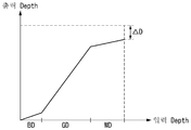
본 발명은 3D 영상이 표시되는 표시 위치와 시청자의 초점 위치를 유사하게 하기 위하여 도 9a 내지 도 9e와 같이 최대 뎁쓰 값을 ΔD 만큼 낮게 변조하되, 전경 영역과 배경 영역 사이의 뎁쓰값 즉 그레이 계조 구간(GD)의 뎁쓰값들 간의 차이를 크게 하여 이미지 전체의 깊이감을 유지할 수 있게 한다.In order to make the display position where the 3D image is displayed and the focus position of the viewer similar to each other, the maximum depth value is modulated by? D as shown in FIG. 9A to FIG. 9E, and the depth value between the foreground area and the background area, The difference between the depth values of the image GD is increased to maintain the depth of the entire image.
도 3은 본 발명의 제2 실시예에 따른 입체 영상 표시장치의 영상 데이터 처리 방법을 보여 주는 흐름도이다.3 is a flowchart illustrating a method of processing image data of a stereoscopic image display device according to a second embodiment of the present invention.
도 3을 참조하면, 본 발명의 영상 데이터 처리 방법은 3D 영상 데이터가 수신되면 그 3D 영상 데이터로부터 뎁쓰 맵을 추출한다.(S31~S33) 여기서, 공지된 2D-3D 변환 알고리즘을 이용하여 2D 영상을 3D 영상으로 변환하고 그 3D 영상으로부터 뎁쓰 맵을 추출할 수도 있다. 3, when the 3D image data is received, the depth map is extracted from the 3D image data (S31 to S33). Here, the 2D image processing method of the present invention extracts a depth map from 2D image data Into a 3D image, and extract a depth map from the 3D image.
본 발명의 영상 데이터 처리 방법은 뎁쓰 맵의 계조값을 기준으로 전경 및 배경 영역을 추출한다.(S34) 이어서, 본 발명의 영상 데이터 처리 방법은 도 9a 내지 도 9e와 같은 뎁쓰 변조 방법을 적용하여 최대 뎁쓰 값을 낮추고 전경 영역과 배경 영역 사이에서 뎁쓰 값들 간의 차이를 크게 변조한다.(S35) 그 결과, 본 발명의 영상 데이터 처리 방법은 입체 영상 표시장치에 3D 입체 영상을 재현할 때 3D 입체 영상의 관심 영역에서 깊이감 손실 없이 시청자의 피로도를 경감할 수 있다. The image data processing method of the present invention extracts the foreground and background areas based on the tone value of the depth map. (S34) Then, the image data processing method of the present invention applies the depth modulation method as shown in FIGS. 9A to 9E (S35). As a result, the method of processing image data of the present invention can reduce the maximum depth value and significantly modulate the difference between the depth values between the foreground area and the background area. (S35) As a result, when the 3D image is reproduced in the stereoscopic image display device, The viewer's fatigue can be reduced without loss of depth in the area of interest of the viewer.
이어서, 본 발명의 영상 데이터 처리 방법은 전경 이미지의 픽셀 데이터들에 대하여 샤프니스(sharpness)를 강조하여 전경 이미지의 선명도를 높이거나 배경 이미지의 픽셀 데이터들에 대하여 블러(blurr) 처리하여 배경 이미지의 선명도를 낮춘다.(S36) 이렇게 전경 이미지의 선명도를 높이거나 배경 이미지의 선명도를 낮추면 선명도 차이로 인하여 시청자가 피로감 없이 자연스러운 입체감을 느끼게 한다. S36 단계에서, 본 발명의 영상 데이터 처리 방법은 전경 이미지의 선명도롤 높임과 아울러, 배경 이미지의 선명도를 낮출 수 있다. According to another aspect of the present invention, there is provided a method of processing image data, the method comprising: enhancing sharpness of pixel data of a foreground image to enhance sharpness of a foreground image or blurring pixel data of a background image, (S36) If the sharpness of the foreground image is raised or the sharpness of the background image is lowered, the viewer can feel the natural three-dimensional feeling without fatigue due to the difference in sharpness. In step S36, the image data processing method of the present invention can increase the sharpness roll of the foreground image and reduce the sharpness of the background image.
샤프니스 강조 알고리즘이나 블러 알고리즘은 공지된 것은 어느 것이든 적용될 수 있다. 일 예로, 본 발명의 영상 데이터 처리 방법은 본원 출원인에 의해 기출원된 대한민국 특허 출원 10-2010-0082390(2010. 08. 25)에서 제안된 알고리즘을 이용할 수 있다. The sharpness emphasis algorithm or blur algorithm can be applied to any known one. For example, the image data processing method of the present invention can use the algorithm proposed in Korean patent application 10-2010-0082390 (Aug. 25, 2010), which is filed by the present applicant.
본 발명의 영상 데이터 처리 방법은 2D 모드에서 입력되는 영상을 기존과 같은 방법으로 처리하여 표시패널 구동부에 입력한다.(S37)In the image data processing method of the present invention, an image input in the 2D mode is processed by a conventional method and input to the display panel drive unit (S37)
도 4는 본 발명의 제3 실시예에 따른 입체 영상 표시장치의 영상 데이터 처리 방법을 보여 주는 흐름도이다.4 is a flowchart illustrating a method of processing image data of a stereoscopic image display apparatus according to a third embodiment of the present invention.
도 4를 참조하면, 본 발명의 영상 데이터 처리 방법은 3D 영상을 분석하여 그 3D 영상이 동영상인지 아니면 정지영상인지를 판단한다.(S41~S44) 이러한 영상 분석 방법은 공지된 어느 것도 이용 가능하다. 예컨대, 본 발명의 영상 데이터 처리 방법은 프레임 간에 픽셀 데이터들을 비교하여 그 차이를 바탕으로 3D 영상의 움직임 여부를 판단하거나 움직임 벡터를 계산하여 3D 영상의 움직임 여부를 판단할 수 있다. 이어서, 본 발명의 영상 데이터 처리 방법은 3D 영상 데이터가 동영상 데이터이면 그 3D 영상 데이터로부터 뎁쓰 맵을 추출한다.(S45)Referring to FIG. 4, the image data processing method of the present invention analyzes a 3D image and determines whether the 3D image is a moving image or a still image (S41 to S44). Any of the known image analysis methods can be used . For example, in the image data processing method of the present invention, it is possible to determine whether a 3D image is moving by comparing pixel data between frames, determining whether the 3D image is moving or calculating a motion vector based on the difference. If the 3D image data is moving image data, the depth map is extracted from the 3D image data. (S45)
본 발명의 영상 데이터 처리 방법은 제2 실시예와 같은 방법으로 뎁쓰 값들을 변조한 후에 전경 영역의 선명도를 높이고 배경 영역의 선명도를 낮춘다.(S46~S48) 이 방법을 통해, 관심 영역이 집중하는 전경 영역의 선명도를 높이거나, 배경 영상의 선명도를 낮추어 동영상에서 시청자로 하여금 자연스러운 입체감을 느끼게 할 수 있다. The image data processing method of the present invention increases the sharpness of the foreground region and lowers the sharpness of the background region after modulating the depth values in the same manner as in the second embodiment (S46 to S48). With this method, It is possible to increase the sharpness of the foreground region or to lower the sharpness of the background image, thereby allowing the viewer to feel a natural three-dimensional feeling in the video.
시청자가 정지 영상을 바라 볼 때 관심 영역의 주 객체들을 바라 본 후에 전경 및 배경 영역의 이미지들도 비교적 자세히 바라 보기 때문에 이미지 전체의 선명도가 균형을 이루는 것이 정지 영상의 화질에서 중요하다. 따라서, 본 발명의 영상 데이터 처리 방법은 S44 단계에서 현재 입력되는 3D 영상이 정지 영상으로 판단되면, 현재 입력되는 3D 영상의 뎁쓰 정보를 입력 뎁쓰 값들로 유지한다.(S49) When the viewer looks at the still image, since the foreground and background areas are viewed in a more detailed way after looking at the main objects of the area of interest, balance of the overall image is important in the still image quality. Accordingly, in the image data processing method of the present invention, if the current 3D image is determined to be a still image in step S44, the depth information of the currently input 3D image is maintained as the input depth values (S49)
본 발명의 영상 데이터 처리 방법은 2D 모드에서 입력되는 영상을 기존과 같은 방법으로 처리하여 표시패널 구동부에 입력한다.(S50)In the image data processing method of the present invention, an image input in the 2D mode is processed by a conventional method and input to the display panel driving unit (S50)
도 5 내지 도 7은 3D 입력 영상으로부터 추출된 뎁쓰 맵의 예들을 보여 주는 도면들이다.5 to 7 are views showing examples of a depth map extracted from a 3D input image.
도 5 내지 도 7을 참조하면, 3D 영상의 원본 이미지로부터 뎁쓰 맵을 추출하면, 그 뎁쓰 맵은 뎁쓰값들을 계조로 표현한다. 뎁쓰 맵에서 화이트 계조 구간이 전경 영역에 속한다. 그레이 계조 구간은 전경 영역과 배경 영역 사이의 경계에 해당한다. 블랙 계조 구간은 관심 영역 뒤의 배경 영역 이미지이다. Referring to FIGS. 5 to 7, when a depth map is extracted from an original image of a 3D image, the depth map expresses depth values in gradation. In the depth map, the white gradation section belongs to the foreground region. The gray gradation section corresponds to the boundary between the foreground region and the background region. The black gradation section is the background region image behind the region of interest.
도 8은 통상적인 선형 뎁쓰 처리 방법을 보여 주는 도면이다. 도 9a 내지 도 9e는 본 발명의 영상 데이터 처리 방법에서 적용되는 뎁쓰 변조 방법을 보여 주는 도면들이다.8 is a diagram showing a conventional linear depth processing method. 9A to 9E are diagrams illustrating a depth modulation method applied to the image data processing method of the present invention.
일반적으로, 원본 3D 영상의 뎁쓰 값들을 변조하지 않으면 입력 뎁쓰 값들과 출력 뎁쓰 값들이 도 8과 같다. 이에 비하여, 본 발명은 도 9a 내지 도 9e와 같은 뎁쓰 변조 커브를 바탕으로 최대 뎁쓰 값을 입력 값 보다 작게 변조하여 도 11과 같이 3D 영상의 표시 위치와 시청자의 초점 위치를 가깝게 조절한다. 그리고 본 발명은 도 9a 내지 도 9e와 같은 뎁쓰 변조 커브를 바탕으로 전경 영역과 배경 영역 사이에서 뎁쓰 값들 간의 차이(또는 간격)을 크게 변조하여 전경 영역과 배경 영역의 깊이감 효과를 높인다. 따라서, 본 발명은 3D 영상의 깊이 효과 손실 없이 시청자의 피로도를 경감할 수 있다.Generally, if the depth values of the original 3D image are not modulated, the input depth values and the output depth values are as shown in FIG. On the other hand, the present invention modulates the maximum depth value smaller than the input value based on the depth modulation curve as shown in FIGS. 9A to 9E to adjust the display position of the 3D image and the focus position of the viewer close to each other as shown in FIG. The present invention greatly modifies the difference (or interval) between depth values between the foreground region and the background region based on the depth modulation curve as shown in FIGS. 9A to 9E, thereby enhancing the depth sensing effect of the foreground region and background region. Therefore, the present invention can reduce the fatigue of viewers without loss of depth effect of the 3D image.
도 9a 내지 도 9e와 같은 뎁쓰 변조 커브는 상대적으로 낮은 기울기의 제1 커브 구간, 상대적으로 높은 기울기의 제2 커브 구간, 및 상대적으로 낮은 기울기의 제3 커브 구간을 포함한다. 제1 커브 구간과 제3 커브 구간 사이에서 제2 커브 구간이 제1 커브 구간의 끝점과 제3 커브 구간의 시작점에 연결된다. 도 9a는 제1 및 제3 커브 구간에서 기울기가 작고 제2 커브 구간에서 기울기가 큰 비선형 뎁쓰 변조 커브이다. 도 9b 내지 도 9e는 제1 및 제3 커브 구간에서 기울기가 작고 제2 커브 구간에서 기울기가 큰 구간별 선형 뎁쓰 변조 커브이다.The depth modulation curve shown in Figs. 9A to 9E includes a first curve section with a relatively low slope, a second curve section with a relatively high slope, and a third curve section with a relatively low slope. A second curve section between the first curve section and the third curve section is connected to an end point of the first curve section and a start point of the third curve section. 9A is a nonlinear depth modulation curve having a small slope in the first and third curve sections and a large slope in the second curve section. Figs. 9B to 9E are linear-depth-dependent modulation curves for each of the first and third curve sections having a small slope and a large slope in the second curve section.
제1 커브 구간은 원본 뎁쓰 맵의 블랙 계조 구간 뎁쓰 값들(x축의 입력 뎁쓰)과 그 뎁쓰값들과 대응하는 변조값들(y축의 출력 뎁쓰)의 교점을 연결한 커브이다. 제2 커브 구간은 원본 뎁쓰 맵의 그레이 계조 구간 뎁쓰 값들(x축의 입력 뎁쓰)과 그 뎁쓰값들과 대응하는 변조값들(y축의 출력 뎁쓰)의 교점을 연결한 커브이다. 제3 커브 구간은 원본 뎁쓰 맵의 화이트 계조 구간 뎁쓰 값(x축의 입력 뎁쓰)과 그 뎁쓰값과 대응하는 변조값들(y축의 출력 뎁쓰)의 교점을 연결한 커브이다. 도 9a 내지 도 9e에서 "WD"는 화이트 계조 구간에서의 입력 뎁쓰 값들, "GD"는 그레이 계조 구간에서의 입력 뎁쓰 값들, "BD"는 블랙 계조 구간에서의 입력 뎁쓰 값들을 각각 의미한다. 화이트 계조 구간(WD), 블랙 계조 구간(BD) 및 그레이 계조 구간(GD) 각각의 기울기와 길이는 3D 영상에 대한 피로도 실험 결과를 바탕으로 최적화된 고정 길이로 설정되거나, 도 9b 내지 도 9e와 같이 3D 영상의 프로그램 장르나 속성 또는 평균 밝기에 따라 가변될 수 있다. The first curve section is a curve connecting the depth values of the black gradation section of the original depth map (input depth of the x axis) and the intersections of the depth values and the corresponding modulation values (output depth of the y axis). The second curve section is a curve connecting the depth values of the gray gradation section of the original depth map (input depth of the x axis) and the intersections of the depth values and the corresponding modulation values (output depth of the y axis). The third curve section is a curve connecting the depth values of the white gradation range of the original depth map (input depth of the x axis) and the intersections of the depth values and the corresponding modulation values (output depth of the y axis). 9A to 9E, "WD" means input depth values in the white gradation section, "GD " means input depth values in the gray gradation section, and" BD " means input depth values in the black gradation section. The slope and the length of each of the white gradation section WD, the black gradation section BD and the gray gradation section GD are set to a fixed length optimized on the basis of the fatigue test result for the 3D image, And can be varied according to the program genre or attribute or the average brightness of the 3D image.
도 10은 전경 영역과 배경 영역 사이의 뎁쓰 값들 간의 차이를 크게 한 뎁쓰 변조 효과를 보여 주는 도면이다. 도 11은 본 발명에서 3D 영상의 표시위치와 시청자의 초점이 유사하게 조절되고 폭주각이 작게 되는 효과를 보여 주는 도면이다.10 is a diagram showing a depth modulation effect in which a difference between depth values between a foreground area and a background area is increased. 11 is a view showing the effect of adjusting the display position of the 3D image and the focus of the viewer similarly and reducing the convergence angle in the present invention.
도 10 및 도 11을 참조하면, 본 발명의 뎁쓰 변조 방법에 의하면, 전경 영역과 배경 영역 사이의 그레이 계조 구간에서 뎁쓰 값들의 차이(D')를 입력 값(D) 보다 크게 변조하여 전경 영역과 배경 영역의 깊이감이 커진다. 10 and 11, according to the depth modulation method of the present invention, the difference (D ') of the depth values in the gray gradation section between the foreground area and the background area is modulated to be larger than the input value (D) The depth of the background area becomes larger.
본 발명의 뎁쓰 변조 방법에 의하면, 최대 뎁쓰 값을 낮추어 객체(O,O')의 상이 맺히는 거리를 A에서 A'으로 길게 하여 폭주각을 θ'으로 감소시킬 수 있다. 또한, 본 발명의 뎁쓰 변조 방법에 의하면, 최대 뎁쓰 값을 낮추어 양안의 초점 거리(A')와 객체의 상이 맺히는 거리(B) 사이의 차이를 좁히고, 양안의 초점 위치에서 좌안 영상과 우안 영상 간의 거리를 C에서 C'로 감소시킨다. 그 결과, 본 발명의 영상 데이터 처리 방법에 의하면 입체 영상 표시장치에서 3D 영상의 깊이 효과 손실 없이 시청자의 피로도를 줄일 수 있다. According to the depth modulation method of the present invention, it is possible to reduce the maximum depth value to lengthen the distance of the image of the object (O, O ') from A to A', thereby reducing the congestion angle to? '. According to the depth modulation method of the present invention, by reducing the maximum depth value, the difference between the focal length A 'of the binocular eye and the distance B of the image of the object is narrowed, and the difference between the left eye image and the right eye image Reduce the distance from C to C '. As a result, according to the image data processing method of the present invention, the fatigue of the viewer can be reduced without loss of depth effect of the 3D image in the stereoscopic image display device.
도 12는 본 발명의 실시예에 따른 입체 영상 표시장치에서 표시패널 구동부와 3D 필터 구동부를 보여 주는 블록도이다. 도 16은 렌티큘라 렌즈 필름이나 스위쳐블 렌즈를 보여 주는 단면도이다. 도 17은 패럴랙스 베리어나 스위쳐블 베리어를 보여 주는 단면도이다. 도 18은 편광 안경 방식의 입체 영상 표시장치를 보여 주는 도면이다. 도 19는 셔터 안경 방식의 입체 영상 표시장치를 보여 주는 도면이다. 12 is a block diagram illustrating a display panel driver and a 3D filter driver in a stereoscopic image display apparatus according to an embodiment of the present invention. 16 is a cross-sectional view showing a lenticular lens film or a switchable lens. 17 is a sectional view showing a parallax barrier or a switchable barrier. FIG. 18 is a diagram showing a stereoscopic image display apparatus of a polarizing glasses system. FIG. Fig. 19 is a diagram showing a stereoscopic image display apparatus of the shutter glasses system. Fig.
본 발명의 입체 영상 표시장치는 도 16 및 도 17과 같은 무안경 표시장치나 도 18 및 도 19와 같은 안경 방식의 입체 영상 표시장치로 구현될 수 있다.The stereoscopic image display apparatus of the present invention can be implemented by a non-eyeglass display apparatus as shown in Figs. 16 and 17 or a stereoscopic image display apparatus of a glasses system as shown in Figs.
도 12를 참조하면, 본 발명의 입체 영상 표시장치는 표시패널(100), 표시패널(100) 상에 접합된 3D 필터(200), 표시패널 구동부, 3D 필터 구동부(210), 타이밍 콘트롤러(101), 3D 영상 데이터 처리부(130) 등을 포함한다.12, the stereoscopic image display apparatus of the present invention includes a
표시패널(100)에는 데이터라인들(105)과 스캔라인들(또는 게이트라인들)(106)이 직교되고, 픽셀들이 매트릭스 형태로 배치된 픽셀 어레이를 포함한다. 픽셀 어레이는 2D 모드에서 2D 영상을 표시하고, 3D 모드에서 좌안 영상과 우안 영상을 표시한다.The
3D 필터(200)는 도 16과 같은 렌티큘라 렌즈 필름이나 스위쳐블 렌즈(LENTI), 도 17과 같은 패럴랙스 베리어나 스위쳐블 베리어(BAR), 또는 도 18과 같은 패턴 리타더(PR), 액티브 리타더(Active retarder) 중 어느 하나로 구현될 수 있다. 3D 필터(200)가 패턴 리타더(PR)로 구현되면, 도 18과 같이 시청자는 편광 안경(PG)을 착용하여 3D 영상을 감상하여야 한다. 스위쳐블 렌즈(LENTI)와 스위쳐블 베리어(BAR)는 액정과 같은 복굴절 매질을 포함하고 3D 필터 구동부(210)에 의해 전기적으로 구동되어 좌안 서브 픽셀들로부터 발산된 빛과 우안 서브 픽셀들로부터 발산되는 빛의 경로를 분리시킨다. 액티브 리타더는 액정과 같은 복굴절 매질을 포함하고 3D 필터 구동부(210)에 의해 전기적으로 구동되어 프레임 기간 단위로 시분할되는 좌안 영상과 우안 영상의 편광 특성을 서로 다르게 변조한다. 3D 필터(200)가 전기적으로 제어되지 않는 광학 부품 예를 들어, 패럴랙스 베리어, 렌티큘라 렌즈 필름, 패턴 리타더(PR)와 같은 광학 부품으로 구현되면, 3D 구동부(210)는 필요 없다. The
표시패널 구동부는 표시패널(100)의 데이터라인들(105)에 2D/3D 영상의 데이터전압들을 공급하기 위한 데이터 구동회로(102)와, 표시패널(100)의 스캔라인들(106)에 스캔펄스(또는 게이트펄스)를 순차적으로 공급하기 위한 스캔 구동회로(103)를 포함한다.The display panel driving unit includes a
데이터 구동회로(102)는 타이밍 콘트롤러(101)로부터 입력되는 디지털 비디오 데이터를 아날로그 감마전압으로 변환하여 데이터전압들을 발생하고 그 데이터전압을 표시패널(100)의 데이터라인들(105)에 공급한다. 액정표시소자의 경우에, 데이터 구동회로(102)는 타이밍 콘트롤러(101)의 제어 하에 데이터라인들(105)에 공급되는 데이터전압의 극성을 반전시킬 수 있다. 스캔 구동회로(103)는 타이밍 콘트롤러(101)의 제어 하에 데이터라인들(105)에 공급되는 데이터전압과 동기되는 스캔펄스를 스캔라인들(106)에 공급하고, 그 스캔펄스를 순차적으로 시프트시킨다. The
3D 필터 구동부(210)는 타이밍 콘트롤러(101)의 제어 하에 3D 모드에서 구동된다. 3D 필터 구동부(210)는 표시패널(100)의 픽셀 어레이에 기입되는 3D 영상 데이터와 동기되어 스위쳐블 렌즈(LENTI), 스위쳐블 베리어(BAR) 또는 액티브 리타더를 구동시킨다.The
타이밍 콘트롤러(101)는 호스트 시스템(110)으로부터 입력되는 2D/3D 입력 영상의 디지털 비디오 데이터(RGB)를 데이터 구동회로(102)에 공급한다. 또한, 타이밍 콘트롤러(101)는 2D/3D 입력 영상의 디지털 비디오 데이터(RGB)와 동기되어 호스트 시스템(110)로부터 입력된 수직 동기신호, 수평 동기신호, 데이터 인에이블 신호, 메인 클럭 등의 타이밍신호를 수신하고, 그 타이밍 신호를 이용하여 표시패널 구동부(102, 103)와 3D 필터 구동부(210) 각각의 동작 타이밍을 제어하고 그 구동부들의 동작 타이밍을 동기시키기 위한 타이밍 제어신호들(DDC, GDC, SBC)을 발생한다.The timing controller 101 supplies digital video data (RGB) of a 2D / 3D input image input from the host system 110 to the
타이밍 콘트롤러(101)는 입력 영상의 프레임 주파수×N(N은 2 이상의 양의 정수) Hz의 프레임 주파수로 높여 표시패널 구동부(102, 103)와 3D 필터 구동부(210)의 동작 주파수를 N 배 체배된 프레임 레이트로 제어할 수 있다. 입력 영상의 프레임 주파수는 NTSC(National Television Standards Committee) 방식에서 60Hz이며, PAL(Phase-Alternating Line) 방식에서 50Hz이다.The timing controller 101 raises the frame frequency of the input image to the frame frequency x N (where N is a positive integer equal to or greater than 2) Hz and multiplies the operation frequency of the display
호스트 시스템(110)과 3D 영상 데이터 처리부(130) 사이에는 3D 데이터 정렬부(120)가 설치될 수 있다. 3D 데이터 정렬부(120)는 3D 모드에서 호스트 시스템(110)으로부터 입력되는 3D 영상의 좌안 영상 데이터와 우안 영상 데이터를 입체 영상 구현 방식에 맞게 재정렬하여 3D 영상 데이터 처리부(130)에 공급한다. 3D 데이터 정렬부(120)는 3D 모드에서 2D 영상 데이터가 입력되면 미리 설정된 2D-3D 영상 변환 알고리즘을 실행하여 2D 영상 데이터로부터 좌안 영상 데이터와 우안 영상 데이터를 생성하고 그 데이터들을 3D 영상 데이터 처리부(130)에 공급할 수도 있다. The 3D data sorting unit 120 may be installed between the host system 110 and the 3D image
3D 영상 데이터 처리부(130)는 3D 모드에서 도 2 내지 도 4와 같은 영상 데이터 처리 방법을 실행하여 뎁쓰 정보가 변조된 3D 영상의 좌안 영상 데이터와 우안 영상 데이터를 타이밍 콘트롤러(101)에 공급한다. 3D 영상 데이터 처리부(130)는 도 2와 같은 영상 데이터 처리 방법을 구현하기 위하여, 도 13과 같이 3D 영상 데이터로부터 뎁쓰 맵을 추출하는 뎁쓰맵 추출부(301), 뎁쓰 맵의 계조를 기준으로 입력 영상을 전경 영역과 배경 영역을 분리하는 이미지 분리부(302), 및 입력 영상의 뎁쓰 값을 변조하는 뎁쓰 변조부(303)를 포함한다. 뎁쓰 변조부(303)는 도 9a 내지 도 9e와 같이 최대 뎁쓰값을 입력 영상의 최대 뎁쓰 값 보다 낮추고, 그레이 계조 구간에 속한 뎁쓰 값들 간의 차이를 입력 영상의 전경 영역과 배경 영역 사이의 뎁쓰 값들 간의 차이보다 크게 변조하는 뎁쓰 변조부(303)를 포함한다. 3D 영상 데이터 처리부(130)는 도 3 및 도 4와 같은 영상 데이터 처리 방법을 구현하기 위하여, 도 14 및 도 15와 같이 3D 영상 데이터를 분석하여 3D 영상 데이터가 동영상 데이터인지 아니면 정지영상 데이터인지를 판단하는 영상 분석부(305); 및 3D 영상 데이터가 동영상 데이터이면, 상기 전경 영역의 데이터들에 대하여 샤프니스를 강조하여 선명도를 높이거나 상기 배경 영역의 데이터들에 대하여 블러 처리를 실시하여 선명도를 선명도 조절부(304)를 더 포함할 수 있다. 선명도 조절부(304)는 샤프니스를 강조하여 선명도를 높이기 위한 수단으로서 공지된 샤프닝 필터를 이용할 수 있고, 블러 처리를 통해 선명도를 낮추기 위한 수단으로서 공지된 스무딩 필터를 이용할 수 있다. 샤프닝 필터의 일 예로서, 라플라시안 필터가 있다. 스무딩 필터의 일 예로서, 평균화 필터, 저역통과 필터, 중간값 필터 등이 있다.The 3D image
호스트 시스템(110)은 네비게이션 시스템, 셋톱박스, DVD 플레이어, 블루레이 플레이어, 개인용 컴퓨터(PC), 홈 시어터 시스템, 방송 수신기, 폰 시스템(Phone system) 중 어느 하나로 구현될 수 있다. 호스트 시스템(110)은 스케일러(scaler)를 이용하여 2D/3D 입력 영상의 디지털 비디오 데이터를 표시패널(PNL, 100)의 해상도에 맞는 포맷으로 변환하고 그 데이터와 함께 타이밍 신호를 타이밍 콘트롤러(101)로 전송한다. The host system 110 may be implemented as any one of a navigation system, a set top box, a DVD player, a Blu-ray player, a personal computer (PC), a home theater system, a broadcast receiver, and a phone system. The host system 110 converts the digital video data of the 2D / 3D input image into a format suitable for the resolution of the display panel (PNL) 100 using a scaler, and transmits a timing signal to the timing controller 101 together with the data. Lt; / RTI >
호스트 시스템(110)은 2D 모드에서 2D 영상을 타이밍 콘트롤러(101)에 공급하는 반면, 3D 모드에서 3D 영상 또는 2D 영상 데이터를 3D 데이터 정렬부(120)에 공급한다. 호스트 시스템(110)은 도시하지 않은 사용자 인터페이스를 통해 입력되는 사용자 데이터에 응답하여 타이밍 콘트롤러에 모드 신호를 전송하여 2D 모드 동작과 3D 모드 동작을 전환할 수 있다. 사용자 인터페이스는 키패드, 키보드, 마우스, 온 스크린 디스플레이(On Screen Display, OSD), 리모트 콘트롤러(Remote controller), 그래픽 유저 인터페이스(Graphic User Interface, GUI), 터치 UI(User Interface), 음성 인식 UI, 3D UI 등으로 구현될 수 있다. 사용자는 사용자 인터페이스를 통해 2D 모드와 3D 모드를 선택할 수 있고, 3D 모드에서 2D-3D 영상 변환을 선택할 수 있다.The host system 110 supplies the 2D image to the timing controller 101 in the 2D mode while supplying the 3D image or the 2D image data to the 3D data sorting unit 120 in the 3D mode. The host system 110 may switch a 2D mode operation and a 3D mode operation by transmitting a mode signal to the timing controller in response to user data input through a user interface (not shown). The user interface includes a keypad, a keyboard, a mouse, an on screen display (OSD), a remote controller, a graphical user interface (GUI), a touch UI (user interface) UI, or the like. The user can select the 2D mode and the 3D mode through the user interface, and select the 2D-3D image conversion in the 3D mode.
한편, 셔터 안경 방식의 입체 영상 표시장치는 표시패널(100)에 기입되는 좌안 영상 데이터와 우안 영상 데이터에 동기되어 온/오프(on/off)되는 셔터 안경(SG)이 필요하다. 이 경우, 호스트 시스템(110)이나 타이밍 콘트롤러(101)는 유/무선 인터페이스를 통해 셔터 안경의 좌안 셔터와 우안 셔터 각각을 전기적으로 제어하여 개폐하기 위한 셔터 제어신호를 셔터 안경(SG)으로 전송할 수 있다. 셔터 안경 방식의 입체 영상 표시장치에서, 표시패널(100)에 접합되는 3D 필터(200)와 3D 구동부(210)는 필요 없다. On the other hand, the three-dimensional image display apparatus of the shutter glasses system requires the left eye image data written in the
도 18에서, 패턴 리타더(PR)는 표시패널(PNL)의 픽셀 어레이에서 기수 번째 라인들과 대향하는 제1 리타더(PR1)와, 표시패널(PNL)의 픽셀 어레이에서 우수 번째 라인들과 대향하는 제2 리타더(PR2)를 포함한다. 픽셀 어레이의 기수 번째 라인들에는 좌안 영상이 표시되는 픽셀들이 배치되고, 우수 번째 라인들에는 우안 영상이 표시되는 픽셀들이 배치된다. 편광 안경(PG)의 좌안 편광 필터는 픽셀 어레이의 기수 번째 라인들에 배치된 픽셀들로부터 발산된 빛의 제1 편광만을 통과시킨다. 편광 안경의 우안 편광 필터는 픽셀 어레이의 우수 번째 라인들에 배치된 픽셀들로부터 발산된 빛의 제2 편광만을 통과시킨다. 따라서, 시청자는 좌안 편광 필터를 통해 좌안 영상이 표시되는 픽셀들만을 보고, 우안 편광 필터를 통해 우안 영상이 표시되는 픽셀들만을 보게 되므로 양안 시차로 인한 입체감을 느낄 수 있다. 18, the pattern retarder PR includes a first retarder PR1 opposed to the odd-numbered lines in the pixel array of the display panel PNL, and a second retarder PR1 opposed to odd-numbered lines in the pixel array of the display panel PNL. And a second retarder PR2 opposed thereto. Pixels in which the left eye image is displayed are arranged in the odd-numbered lines of the pixel array, and pixels in which the right eye image is displayed in the even-numbered lines are arranged. The left eye polarizing filter of the polarizing glasses PG passes only the first polarized light of the light emitted from the pixels arranged in the odd-numbered lines of the pixel array. The right eye polarizing filter of the polarizing glasses passes only the second polarized light of the light emitted from the pixels arranged on the even lines of the pixel array. Therefore, the viewer sees only the pixels on which the left eye image is displayed through the left eye polarization filter, and only the pixels on which the right eye image is displayed through the right eye polarization filter, so that the stereoscopic effect due to the binocular parallax can be felt.
도 19와 같은 셔터 안경 방식의 입체 영상 표시장치의 표시패널(PNL)에는 기수 번째 프레임 기간(F(n)) 동안 좌안 영상 데이터(RGBL)가 기입된다. 셔터 안경(ST)의 좌안 렌즈(STL)는 전기적으로 제어되어 표시패널(PNL)에 표시된 좌안 영상 데이터(RGBL)와 동기되어 기수 번째 프레임 기간(F(n)) 동안 개방되는 반면, 우수 번째 프레임 기간(F(n+1)) 동안 차단된다. 표시패널(PNL)에는 우수 번째 프레임 기간(F(n+1)) 동안 우안 영상 데이터(RGBR)가 기입된다. 셔터 안경(ST)의 우안 렌즈(STR)는 전기적으로 제어되어 표시패널(PNL)에 표시된 우안 영상 데이터(RGBR)와 동기되어 우수 번째 프레임 기간(F(n+1)) 동안 개방되는 반면, 기수 번째 프레임 기간(F(n)) 동안 차단된다. A display panel (PNL) of the shutter glasses system three-dimensional display device such as Fig. 19 is written into the left-eye image data (RGB L) during odd-numbered frame periods (F (n)). The left eye lens ST L of the shutter glasses ST is electrically controlled and opened for the odd-numbered frame period F (n) in synchronization with the left eye image data RGB L displayed on the display panel PNL, Th frame period F (n + 1). The right eye image data RGB R is written to the display panel PNL during the odd-numbered frame period F (n + 1). While the opening for the right eye lens (ST R) is electrically controlled by a display panel the right eye video data period (RGB R) and is synchronized solid-th frame (F (n + 1)) shown in (PNL) of the shutter glasses (ST) , And is interrupted during the odd-numbered frame period F (n).
이상 설명한 내용을 통해 당업자라면 본 발명의 기술사상을 일탈하지 아니하는 범위 내에서 다양한 변경 및 수정이 가능함을 알 수 있을 것이다. 따라서, 본 발명은 상세한 설명에 기재된 내용으로 한정되는 것이 아니라 특허 청구의 범위에 의해 정하여져야만 할 것이다.
It will be apparent to those skilled in the art that various modifications and variations can be made in the present invention without departing from the spirit or scope of the invention. Therefore, the present invention should not be limited to the details described in the detailed description, but should be defined by the claims.
PNL, 100 : 표시패널 101 : 타이밍 콘트롤러
102 : 데이터 구동회로 103 : 스캔 구동회로
110 : 호스트 시스템 120 : 3D 데이터 정렬부
130 : 3D 영상 데이터 처리부 200 : 3D 필터
LENTI : 렌티큘러 렌즈, 스위쳐블 렌즈
BAR : 패럴랙스 베리어, 스위쳐블 베리어PNL, 100: display panel 101: timing controller
102: data driving circuit 103: scan driving circuit
110: host system 120: 3D data sorting unit
130: 3D image data processing unit 200: 3D filter
LENTI: Lenticular lens, switchable lens
BAR: Parallax Barrier, Switcher Barrier
Claims (12)
상기 뎁쓰 맵의 계조를 기준으로 상기 입력 영상의 이미지를 전경 영역과 배경 영역으로 분리하는 단계; 및
상기 입력 영상의 최대 뎁쓰 값을 낮추고 상기 뎁쓰 맵의 그레이 계조 구간에 속한 뎁쓰 값들 간의 차이를 입력 영상의 전경 영역과 배경 영역 사이의 뎁쓰 값들 간의 차이 보다 크게 조절하는 뎁쓰 값들을 변조하는 단계를 포함하는 것을 특징으로 하는 영상 데이터 처리 방법.Extracting a depth map from an input image;
Separating an image of the input image into a foreground region and a background region based on the grayscale of the depth map; And
And modulating depth values for lowering the maximum depth value of the input image and adjusting the difference between depth values belonging to the gray gradation section of the depth map to be larger than the difference between depth values between the foreground area and the background area of the input image Wherein the image data processing method comprises the steps of:
상기 전경 영역의 뎁쓰 값들은 상기 뎁쓰 맵에서 화이트 계조 구간에 속한 이미지의 뎁쓰 값들이고,
상기 배경 영역의 뎁쓰 값들은 상기 뎁쓰 맵에서 블랙 계조 구간에 속한 이미지의 뎁쓰 값들이고, ,
상기 그레이 계조 구간은 상기 화이트 계조 구간과 상기 블랙 계조 구간 사이의 계조값들로 이루어지는 이미지의 뎁쓰 값들을 포함하는 것을 특징으로 하는 영상 데이터 처리 방법.The method according to claim 1,
The depth values of the foreground region are the depth values of the image belonging to the white gradation section in the depth map,
Wherein the depth values of the background area are depth values of an image belonging to a black gradation section in the depth map,
Wherein the gray gradation section includes depth values of an image including gray level values between the white gradation section and the black gradation section.
상기 전경 영역의 데이터들에 대하여 샤프니스를 강조하여 선명도를 높이거나, 상기 배경 영역의 데이터들에 대하여 블러 처리를 실시하여 선명도를 낮추는 단계를 더 포함하는 것을 특징으로 하는 영상 데이터 처리 방법.The method according to claim 1,
Further comprising enhancing sharpness of data of the foreground region to enhance sharpness or blurring data of the background region to lower sharpness.
상기 전경 영역의 데이터들에 대하여 샤프니스를 강조하여 선명도를 높이고, 상기 배경 영역의 데이터들에 대하여 블러 처리를 실시하여 선명도를 낮추는 단계를 더 포함하는 것을 특징으로 하는 영상 데이터 처리 방법.The method according to claim 1,
Further comprising enhancing sharpness of data of the foreground region to enhance sharpness and blurring data of the background region to lower sharpness.
상기 입력 영상을 분석하여 상기 입력 영상이 동영상인지 아니면 정지영상인지를 판단하는 단계;
상기 입력 영상이 동영상 데이터이면, 상기 전경 영역의 데이터들에 대하여 샤프니스를 강조하여 선명도를 높이거나, 상기 배경 영역의 데이터들에 대하여 블러 처리를 실시하여 선명도를 낮추는 단계;
상기 입력 영상이 정지영상이면, 입력 영상의 뎁쓰 정보를 입력 뎁쓰 값들로 유지하는 단계를 더 포함하는 것을 특징으로 하는 영상 데이터 처리 방법.The method according to claim 1,
Analyzing the input image to determine whether the input image is a moving image or a still image;
If the input image is moving image data, enhancing sharpness by emphasizing sharpness of data in the foreground area, or blurring data of the background area to lower sharpness;
If the input image is a still image, maintaining the depth information of the input image as input depth values.
상기 입력 영상을 분석하여 상기 입력 영상이 동영상인지 아니면 정지영상인지를 판단하는 단계;
상기 입력 영상이 상기 동영상이면, 상기 전경 영역의 데이터들에 대하여 샤프니스를 강조하여 선명도를 높이고, 상기 배경 영역의 데이터들에 대하여 블러 처리를 실시하여 선명도를 낮추는 단계;
상기 입력 영상이 상기 정지영상이면, 3D 영상의 뎁쓰 값들은 입력 뎁쓰 값들로 유지되는 것을 특징으로 하는 영상 데이터 처리 방법.The method according to claim 1,
Analyzing the input image to determine whether the input image is a moving image or a still image;
If the input image is the moving image, enhancing sharpness by emphasizing sharpness of data in the foreground area, and blurring data of the background area to lower sharpness;
Wherein if the input image is the still image, the depth values of the 3D image are maintained as input depth values.
상기 뎁쓰 값들을 변조하는 단계는,
상기 전경 영역의 뎁쓰 값들을 변조하기 위한 제1 커브 구간, 상기 그레이 계조 구간의 뎁쓰 값들을 변조하기 위한 제2 커브 구간, 및 상기 배경 영역의 뎁쓰 값들을 변조하기 위한 제3 커브 구간으로 나뉘어진 뎁쓰 변조 커브에 기초하여 상기 뎁쓰값들을 변조하고,
상기 뎁쓰 변조 커브는 입력 뎁쓰 값들이 정의된 x축과 출력 뎁쓰 값들이 정의된 y축 사이에서 구간별로 다른 기울기를 가지며,
상기 제2 커브 구간의 기울기는 상기 제1 및 제3 커브 구간들 각각의 기울기보다 크고,
상기 뎁쓰 값들을 변조하는 단계는,
상기 뎁쓰 커브의 기울기에 비례하는 가중치를 상기 뎁쓰 값들에 곱하는 것을 특징으로 하는 영상 데이터 처리 방법.7. The method according to any one of claims 2 to 6,
Wherein modulating the depth values comprises:
A first curve section for modulating the depth values of the foreground area, a second curve section for modulating the depth values of the gray gradation section, and a third curve section for modulating the depth values of the background area, Modulate the depth values based on a modulation curve,
Wherein the depth modulation curve has a different slope for each section between the x axis for which the input depth values are defined and the y axis for which the output depth values are defined,
The slope of the second curve section is larger than the slope of each of the first and third curve sections,
Wherein modulating the depth values comprises:
Wherein the depth values are multiplied by a weight proportional to a slope of the depth curve.
상기 뎁쓰 값들을 변조하는 단계는,
상기 전경 영역의 뎁쓰 값들을 변조하기 위한 제1 커브 구간, 상기 그레이 계조 구간의 뎁쓰 값들을 변조하기 위한 제2 커브 구간, 및 상기 배경 영역의 뎁쓰 값들을 변조하기 위한 제3 커브 구간으로 나뉘어진 뎁쓰 변조 커브가 저장된 룩업 테이블을 이용하여 상기 뎁쓰값들을 변조하고,
상기 뎁쓰 변조 커브는 입력 뎁쓰 값들이 정의된 x축과 출력 뎁쓰 값들이 정의된 y축 사이에서 구간별로 다른 기울기를 가지며,
상기 제2 커브 구간의 기울기는 상기 제1 및 제3 커브 구간들 각각의 기울기보다 큰 것을 특징으로 하는 영상 데이터 처리 방법.7. The method according to any one of claims 2 to 6,
Wherein modulating the depth values comprises:
A first curve section for modulating the depth values of the foreground area, a second curve section for modulating the depth values of the gray gradation section, and a third curve section for modulating the depth values of the background area, Modulating the depth values using a lookup table stored with a modulation curve,
Wherein the depth modulation curve has a different slope for each section between the x axis for which the input depth values are defined and the y axis for which the output depth values are defined,
Wherein the slope of the second curve section is greater than the slope of each of the first and third curve sections.
상기 뎁쓰 맵의 계조를 기준으로 상기 입력 영상의 이미지를 전경 영역과 배경 영역으로 분리하는 이미지 분리부; 및
상기 입력 영상의 최대 뎁쓰 값을 낮추고 상기 뎁쓰 맵의 그레이 계조 구간에 속한 뎁쓰 값들 간의 차이를 입력 영상의 전경 영역과 배경 영역 사이의 뎁쓰 값들 간의 차이 보다 크게 조절하는 뎁쓰 변조부를 포함하는 것을 특징으로 하는 입체 영상 표시장치.A depth map extracting unit for extracting a depth map from an input image;
An image separator for separating the image of the input image into a foreground area and a background area based on the grayscale of the depth map; And
And a depth modulation unit for lowering the maximum depth value of the input image and adjusting the difference between the depth values belonging to the gray gradation section of the depth map to be larger than the difference between the depth values between the foreground area and the background area of the input image Stereoscopic image display device.
상기 전경 영역의 뎁쓰 값들은 상기 뎁쓰 맵에서 화이트 계조 구간에 속한 이미지의 뎁쓰 값들이고,
상기 배경 영역의 뎁쓰 값들은 상기 뎁쓰 맵에서 블랙 계조 구간에 속한 이미지의 뎁쓰 값들이고,
상기 그레이 계조 구간은 상기 화이트 계조 구간과 상기 블랙 계조 구간 사이의 계조값들로 이루어지는 이미지의 뎁쓰 값들을 포함하는 것을 특징으로 하는 입체 영상 표시장치.10. The method of claim 9,
The depth values of the foreground region are the depth values of the image belonging to the white gradation section in the depth map,
The depth values of the background area are depth values of the image belonging to the black gradation section in the depth map,
Wherein the gray gradation section includes depth values of an image including gray level values between the white gradation section and the black gradation section.
상기 전경 영역의 데이터들에 대하여 샤프니스를 강조하여 선명도를 높이거나, 상기 배경 영역의 데이터들에 대하여 블러 처리를 실시하여 선명도를 낮추는 선명도 조절부를 더 포함하는 것을 특징으로 하는 입체 영상 표시장치.10. The method of claim 9,
Further comprising a sharpness adjustment unit for enhancing sharpness of the data in the foreground area to enhance sharpness or blurring data in the background area to lower sharpness.
상기 입력 영상을 분석하여 상기 입력 영상이 동영상인지 아니면 정지영상인지를 판단하는 영상 분석부; 및
상기 입력 영상이 상기 동영상 데이터이면, 상기 전경 영역의 데이터들에 대하여 샤프니스를 강조하여 선명도를 높이거나, 상기 배경 영역의 데이터들에 대하여 블러 처리를 실시하여 선명도를 선명도 조절부를 더 포함하고,
상기 입력 영상이 상기 정지영상이면, 입력 영상의 뎁쓰 값들은 입력 뎁쓰 값들로 유지되는 것을 특징으로 하는 입체 영상 표시장치.
10. The method of claim 9,
An image analyzer for analyzing the input image to determine whether the input image is a moving image or a still image; And
Further comprising a sharpness adjusting unit for sharpening the sharpness of the data in the foreground region to increase the sharpness or blurring the data of the background region if the input image is the moving image data,
Wherein the depth values of the input image are maintained at input depth values if the input image is the still image.
Priority Applications (4)
| Application Number | Priority Date | Filing Date | Title |
|---|---|---|---|
| KR1020120083844A KR101470693B1 (en) | 2012-07-31 | 2012-07-31 | Image data processing method and stereoscopic image display using the same |
| US13/708,286 US9355455B2 (en) | 2012-07-31 | 2012-12-07 | Image data processing method and stereoscopic image display using the same |
| CN201210558722.XA CN103581640B (en) | 2012-07-31 | 2012-12-20 | Image processing method and use its stereoscopic image display |
| TW101149210A TWI598846B (en) | 2012-07-31 | 2012-12-21 | Image data processing method and stereoscopic image display using the same |
Applications Claiming Priority (1)
| Application Number | Priority Date | Filing Date | Title |
|---|---|---|---|
| KR1020120083844A KR101470693B1 (en) | 2012-07-31 | 2012-07-31 | Image data processing method and stereoscopic image display using the same |
Publications (2)
| Publication Number | Publication Date |
|---|---|
| KR20140017224A KR20140017224A (en) | 2014-02-11 |
| KR101470693B1 true KR101470693B1 (en) | 2014-12-08 |
Family
ID=50025021
Family Applications (1)
| Application Number | Title | Priority Date | Filing Date |
|---|---|---|---|
| KR1020120083844A Active KR101470693B1 (en) | 2012-07-31 | 2012-07-31 | Image data processing method and stereoscopic image display using the same |
Country Status (4)
| Country | Link |
|---|---|
| US (1) | US9355455B2 (en) |
| KR (1) | KR101470693B1 (en) |
| CN (1) | CN103581640B (en) |
| TW (1) | TWI598846B (en) |
Families Citing this family (37)
| Publication number | Priority date | Publication date | Assignee | Title |
|---|---|---|---|---|
| US10262462B2 (en) | 2014-04-18 | 2019-04-16 | Magic Leap, Inc. | Systems and methods for augmented and virtual reality |
| JP5770804B2 (en) * | 2013-09-30 | 2015-08-26 | グリー株式会社 | Notification management method, notification management server, and notification management program |
| US9967546B2 (en) | 2013-10-29 | 2018-05-08 | Vefxi Corporation | Method and apparatus for converting 2D-images and videos to 3D for consumer, commercial and professional applications |
| US20150116458A1 (en) | 2013-10-30 | 2015-04-30 | Barkatech Consulting, LLC | Method and apparatus for generating enhanced 3d-effects for real-time and offline appplications |
| US10158847B2 (en) | 2014-06-19 | 2018-12-18 | Vefxi Corporation | Real—time stereo 3D and autostereoscopic 3D video and image editing |
| EP2993901A1 (en) * | 2014-09-03 | 2016-03-09 | Samsung Electronics Co., Ltd. | Method for displaying images and electronic device thereof |
| CN105991989A (en) * | 2015-01-30 | 2016-10-05 | 乐视致新电子科技(天津)有限公司 | Film-type patterned retarder 3D display method and display device |
| TWI566601B (en) * | 2015-02-25 | 2017-01-11 | 光寶科技股份有限公司 | Image processing device and image depth processing method |
| US10121280B2 (en) | 2015-11-13 | 2018-11-06 | Vefxi Corporation | 3D system including rendering with three dimensional transformation |
| US10277879B2 (en) | 2015-11-13 | 2019-04-30 | Vefxi Corporation | 3D system including rendering with eye displacement |
| US10225542B2 (en) | 2015-11-13 | 2019-03-05 | Vefxi Corporation | 3D system including rendering with angular compensation |
| US10148932B2 (en) | 2015-11-13 | 2018-12-04 | Vefxi Corporation | 3D system including object separation |
| US10242448B2 (en) | 2015-11-13 | 2019-03-26 | Vefxi Corporation | 3D system including queue management |
| US10148933B2 (en) | 2015-11-13 | 2018-12-04 | Vefxi Corporation | 3D system including rendering with shifted compensation |
| US10277877B2 (en) | 2015-11-13 | 2019-04-30 | Vefxi Corporation | 3D system including a neural network |
| US10284837B2 (en) | 2015-11-13 | 2019-05-07 | Vefxi Corporation | 3D system including lens modeling |
| US10122987B2 (en) | 2015-11-13 | 2018-11-06 | Vefxi Corporation | 3D system including additional 2D to 3D conversion |
| US10277880B2 (en) | 2015-11-13 | 2019-04-30 | Vefxi Corporation | 3D system including rendering with variable displacement |
| WO2017083509A1 (en) * | 2015-11-13 | 2017-05-18 | Craig Peterson | Three dimensional system |
| CN105608699B (en) * | 2015-12-25 | 2019-03-29 | 联想(北京)有限公司 | A kind of image processing method and electronic equipment |
| WO2017142712A1 (en) | 2016-02-18 | 2017-08-24 | Craig Peterson | 3d system including a marker mode |
| US10439980B2 (en) * | 2016-08-30 | 2019-10-08 | Ncr Corporation | Cross-messaging identity mapping |
| WO2018136951A1 (en) * | 2017-01-23 | 2018-07-26 | Virtual Diamond Boutique Inc. | System, method and computer-accessible medium for displaying a three-dimensional digital version of an object |
| KR102337888B1 (en) * | 2017-03-16 | 2021-12-10 | 삼성디스플레이 주식회사 | Image Processing method and apparatus for LCD Device |
| CN108630156A (en) * | 2017-03-24 | 2018-10-09 | 京东方科技集团股份有限公司 | Display device and display method |
| JP7149615B2 (en) * | 2017-12-05 | 2022-10-07 | 国立大学法人 筑波大学 | Image display device, image display method, and image display system |
| US10628952B2 (en) | 2017-12-11 | 2020-04-21 | Google Llc | Dual-band stereo depth sensing system |
| EP3644604A1 (en) * | 2018-10-23 | 2020-04-29 | Koninklijke Philips N.V. | Image generating apparatus and method therefor |
| KR102593569B1 (en) * | 2019-01-08 | 2023-10-25 | 삼성전자주식회사 | Electronic apparatus and control method thereof |
| SG11202107728SA (en) | 2019-01-17 | 2021-08-30 | The Royal Institution For The Advancement Of Learning/Mcgill Univ | System and method for digital measurement of stereo vision |
| JP7253971B2 (en) * | 2019-05-09 | 2023-04-07 | 日本放送協会 | 3D image depth control device and program |
| US11641456B2 (en) * | 2020-09-14 | 2023-05-02 | Himax Technologies Limited | Image rendering method and apparatus |
| US11790545B2 (en) | 2020-09-14 | 2023-10-17 | Himax Technologies Limited | Method and apparatus to control light source in structured light imaging |
| US11112880B1 (en) * | 2020-11-02 | 2021-09-07 | Dell Products L.P. | Selectively controlling a monitor's on-screen display with a keyboard or mouse |
| JP7495644B2 (en) * | 2020-12-11 | 2024-06-05 | 日本電信電話株式会社 | Image display method, image display device, and program |
| JP2024521898A (en) * | 2021-06-02 | 2024-06-04 | ドルビー ラボラトリーズ ライセンシング コーポレイション | Method, Encoder, and Display Device for Representing a 3D Scene and Its Depth Plane Data - Patent application |
| CN113660479B (en) * | 2021-08-18 | 2024-08-06 | 深圳未来立体科技有限公司 | Position switching method and system for 3D playing device |
Citations (4)
| Publication number | Priority date | Publication date | Assignee | Title |
|---|---|---|---|---|
| KR20110014067A (en) * | 2009-08-04 | 2011-02-10 | 삼성전자주식회사 | Method and system for converting stereo content |
| KR20110052207A (en) * | 2009-11-12 | 2011-05-18 | 삼성전자주식회사 | Image processing apparatus and method for improving depth perception |
| KR20120007289A (en) * | 2010-07-14 | 2012-01-20 | 삼성전자주식회사 | Display device and its three-dimensional setting method |
| KR20120067879A (en) * | 2010-12-16 | 2012-06-26 | 한국전자통신연구원 | Apparatus and method for offering 3d video processing, rendering, and displaying |
Family Cites Families (11)
| Publication number | Priority date | Publication date | Assignee | Title |
|---|---|---|---|---|
| US7702131B2 (en) * | 2005-10-13 | 2010-04-20 | Fujifilm Corporation | Segmenting images and simulating motion blur using an image sequence |
| US7990427B2 (en) * | 2006-08-21 | 2011-08-02 | Micron Technology, Inc. | Method and apparatus for applying tonal correction to images |
| TWI322616B (en) | 2006-10-13 | 2010-03-21 | Altek Corp | Method for automatically adjusting the parameters of a photograph according to a user's habitual behavior |
| US8213711B2 (en) * | 2007-04-03 | 2012-07-03 | Her Majesty The Queen In Right Of Canada As Represented By The Minister Of Industry, Through The Communications Research Centre Canada | Method and graphical user interface for modifying depth maps |
| CN101682794B (en) | 2007-05-11 | 2012-05-02 | 皇家飞利浦电子股份有限公司 | Method, apparatus and system for processing depth-related information |
| JP5434231B2 (en) * | 2009-04-24 | 2014-03-05 | ソニー株式会社 | Image information processing apparatus, imaging apparatus, image information processing method, and program |
| TW201208344A (en) | 2010-08-03 | 2012-02-16 | Himax Media Solutions Inc | System and method of enhancing depth of a 3D image |
| KR20120023268A (en) * | 2010-09-01 | 2012-03-13 | 삼성전자주식회사 | Display apparatus and image generating method thereof |
| KR101783663B1 (en) | 2010-11-05 | 2017-10-11 | 엘지디스플레이 주식회사 | Image display device and driving method for thereof |
| US9554114B2 (en) * | 2011-09-15 | 2017-01-24 | Broadcom Corporation | Depth range adjustment for three-dimensional images |
| US20130162762A1 (en) * | 2011-12-22 | 2013-06-27 | 2Dinto3D LLC | Generating a supplemental video stream from a source video stream in a first output type format used to produce an output video stream in a second output type format |
-
2012
- 2012-07-31 KR KR1020120083844A patent/KR101470693B1/en active Active
- 2012-12-07 US US13/708,286 patent/US9355455B2/en active Active
- 2012-12-20 CN CN201210558722.XA patent/CN103581640B/en active Active
- 2012-12-21 TW TW101149210A patent/TWI598846B/en active
Patent Citations (4)
| Publication number | Priority date | Publication date | Assignee | Title |
|---|---|---|---|---|
| KR20110014067A (en) * | 2009-08-04 | 2011-02-10 | 삼성전자주식회사 | Method and system for converting stereo content |
| KR20110052207A (en) * | 2009-11-12 | 2011-05-18 | 삼성전자주식회사 | Image processing apparatus and method for improving depth perception |
| KR20120007289A (en) * | 2010-07-14 | 2012-01-20 | 삼성전자주식회사 | Display device and its three-dimensional setting method |
| KR20120067879A (en) * | 2010-12-16 | 2012-06-26 | 한국전자통신연구원 | Apparatus and method for offering 3d video processing, rendering, and displaying |
Also Published As
| Publication number | Publication date |
|---|---|
| TW201405483A (en) | 2014-02-01 |
| KR20140017224A (en) | 2014-02-11 |
| CN103581640A (en) | 2014-02-12 |
| TWI598846B (en) | 2017-09-11 |
| US9355455B2 (en) | 2016-05-31 |
| US20140035902A1 (en) | 2014-02-06 |
| CN103581640B (en) | 2016-08-03 |
Similar Documents
| Publication | Publication Date | Title |
|---|---|---|
| KR101470693B1 (en) | Image data processing method and stereoscopic image display using the same | |
| KR101777875B1 (en) | Stereoscopic image display and method of adjusting stereoscopic image thereof | |
| CN102822886B (en) | Stereoscopic image display device, display system, driving method, driving device, display control method, and display control device | |
| US9380284B2 (en) | Image processing method, image processing device and recording medium | |
| JP5235976B2 (en) | Video playback method and video playback apparatus | |
| GB2480363A (en) | Stereoscopic image display with reduced ghosting | |
| TWI432013B (en) | 3d image display method and image timing control unit | |
| KR20130056133A (en) | Display apparatus and driving method thereof | |
| CN102572479A (en) | Method and apparatus for providing stereoscopic image | |
| KR101731113B1 (en) | 2d-3d image conversion method and stereoscopic image display using the same | |
| US8952957B2 (en) | Three-dimensional display apparatus | |
| JP2003189208A (en) | Display system and display method | |
| US20130063420A1 (en) | Stereoscopic Image Display Method, Stereoscopic Image Driving Method, and Stereoscopic Image Display System | |
| KR102334031B1 (en) | Autostereoscopic 3d display device and driving method thereof | |
| KR20150038954A (en) | Image processing device and method for autostereoscopic image display | |
| CN102868904A (en) | Stereoscopic image display method and image timing controller | |
| KR102275491B1 (en) | Crosstalk reduction method and device, and multi-view autostereoscopic image display using the same | |
| JP5561081B2 (en) | Image display device | |
| KR101681777B1 (en) | Scanning backlight driving method and stereoscopic image display device using the same | |
| KR102080611B1 (en) | Device and method of generating a new image for multi-view autostereoscopic image display | |
| KR101773608B1 (en) | Stereoscopic image display | |
| KR101992161B1 (en) | Stereoscopic image display and polarity control method thereof | |
| KR102135914B1 (en) | Image data processing method and multi-view autostereoscopic image display using the same | |
| KR102143944B1 (en) | Method of adjusting three-dimensional effect and stereoscopic image display using the same | |
| JP2012137696A (en) | Liquid crystal display device |
Legal Events
| Date | Code | Title | Description |
|---|---|---|---|
| PA0109 | Patent application |
St.27 status event code: A-0-1-A10-A12-nap-PA0109 |
|
| A201 | Request for examination | ||
| PA0201 | Request for examination |
St.27 status event code: A-1-2-D10-D11-exm-PA0201 |
|
| PG1501 | Laying open of application |
St.27 status event code: A-1-1-Q10-Q12-nap-PG1501 |
|
| D13-X000 | Search requested |
St.27 status event code: A-1-2-D10-D13-srh-X000 |
|
| D14-X000 | Search report completed |
St.27 status event code: A-1-2-D10-D14-srh-X000 |
|
| E902 | Notification of reason for refusal | ||
| PE0902 | Notice of grounds for rejection |
St.27 status event code: A-1-2-D10-D21-exm-PE0902 |
|
| P11-X000 | Amendment of application requested |
St.27 status event code: A-2-2-P10-P11-nap-X000 |
|
| P13-X000 | Application amended |
St.27 status event code: A-2-2-P10-P13-nap-X000 |
|
| E701 | Decision to grant or registration of patent right | ||
| PE0701 | Decision of registration |
St.27 status event code: A-1-2-D10-D22-exm-PE0701 |
|
| GRNT | Written decision to grant | ||
| PR0701 | Registration of establishment |
St.27 status event code: A-2-4-F10-F11-exm-PR0701 |
|
| PR1002 | Payment of registration fee |
St.27 status event code: A-2-2-U10-U11-oth-PR1002 Fee payment year number: 1 |
|
| PG1601 | Publication of registration |
St.27 status event code: A-4-4-Q10-Q13-nap-PG1601 |
|
| FPAY | Annual fee payment |
Payment date: 20171116 Year of fee payment: 4 |
|
| PR1001 | Payment of annual fee |
St.27 status event code: A-4-4-U10-U11-oth-PR1001 Fee payment year number: 4 |
|
| FPAY | Annual fee payment |
Payment date: 20181114 Year of fee payment: 5 |
|
| PR1001 | Payment of annual fee |
St.27 status event code: A-4-4-U10-U11-oth-PR1001 Fee payment year number: 5 |
|
| PR1001 | Payment of annual fee |
St.27 status event code: A-4-4-U10-U11-oth-PR1001 Fee payment year number: 6 |
|
| PR1001 | Payment of annual fee |
St.27 status event code: A-4-4-U10-U11-oth-PR1001 Fee payment year number: 7 |
|
| PR1001 | Payment of annual fee |
St.27 status event code: A-4-4-U10-U11-oth-PR1001 Fee payment year number: 8 |
|
| PR1001 | Payment of annual fee |
St.27 status event code: A-4-4-U10-U11-oth-PR1001 Fee payment year number: 9 |
|
| PR1001 | Payment of annual fee |
St.27 status event code: A-4-4-U10-U11-oth-PR1001 Fee payment year number: 10 |
|
| PR1001 | Payment of annual fee |
St.27 status event code: A-4-4-U10-U11-oth-PR1001 Fee payment year number: 11 |
|
| PR1001 | Payment of annual fee |
St.27 status event code: A-4-4-U10-U11-oth-PR1001 Fee payment year number: 12 |
|
| U11 | Full renewal or maintenance fee paid |
Free format text: ST27 STATUS EVENT CODE: A-4-4-U10-U11-OTH-PR1001 (AS PROVIDED BY THE NATIONAL OFFICE) Year of fee payment: 12 |