KR101436624B1 - Apparatus, method and computer readable recording medium for detecting an error of a lane data for lane maintenance support - Google Patents
Apparatus, method and computer readable recording medium for detecting an error of a lane data for lane maintenance support Download PDFInfo
- Publication number
- KR101436624B1 KR101436624B1 KR1020130013973A KR20130013973A KR101436624B1 KR 101436624 B1 KR101436624 B1 KR 101436624B1 KR 1020130013973 A KR1020130013973 A KR 1020130013973A KR 20130013973 A KR20130013973 A KR 20130013973A KR 101436624 B1 KR101436624 B1 KR 101436624B1
- Authority
- KR
- South Korea
- Prior art keywords
- lane
- vehicle
- parameter
- equivalent model
- state information
- Prior art date
- Legal status (The legal status is an assumption and is not a legal conclusion. Google has not performed a legal analysis and makes no representation as to the accuracy of the status listed.)
- Active
Links
Images


Classifications
-
- B—PERFORMING OPERATIONS; TRANSPORTING
- B60—VEHICLES IN GENERAL
- B60W—CONJOINT CONTROL OF VEHICLE SUB-UNITS OF DIFFERENT TYPE OR DIFFERENT FUNCTION; CONTROL SYSTEMS SPECIALLY ADAPTED FOR HYBRID VEHICLES; ROAD VEHICLE DRIVE CONTROL SYSTEMS FOR PURPOSES NOT RELATED TO THE CONTROL OF A PARTICULAR SUB-UNIT
- B60W30/00—Purposes of road vehicle drive control systems not related to the control of a particular sub-unit, e.g. of systems using conjoint control of vehicle sub-units
- B60W30/10—Path keeping
- B60W30/12—Lane keeping
-
- B—PERFORMING OPERATIONS; TRANSPORTING
- B62—LAND VEHICLES FOR TRAVELLING OTHERWISE THAN ON RAILS
- B62D—MOTOR VEHICLES; TRAILERS
- B62D15/00—Steering not otherwise provided for
- B62D15/02—Steering position indicators ; Steering position determination; Steering aids
- B62D15/025—Active steering aids, e.g. helping the driver by actively influencing the steering system after environment evaluation
-
- B—PERFORMING OPERATIONS; TRANSPORTING
- B60—VEHICLES IN GENERAL
- B60R—VEHICLES, VEHICLE FITTINGS, OR VEHICLE PARTS, NOT OTHERWISE PROVIDED FOR
- B60R11/00—Arrangements for holding or mounting articles, not otherwise provided for
- B60R11/04—Mounting of cameras operative during drive; Arrangement of controls thereof relative to the vehicle
-
- B—PERFORMING OPERATIONS; TRANSPORTING
- B60—VEHICLES IN GENERAL
- B60W—CONJOINT CONTROL OF VEHICLE SUB-UNITS OF DIFFERENT TYPE OR DIFFERENT FUNCTION; CONTROL SYSTEMS SPECIALLY ADAPTED FOR HYBRID VEHICLES; ROAD VEHICLE DRIVE CONTROL SYSTEMS FOR PURPOSES NOT RELATED TO THE CONTROL OF A PARTICULAR SUB-UNIT
- B60W10/00—Conjoint control of vehicle sub-units of different type or different function
- B60W10/20—Conjoint control of vehicle sub-units of different type or different function including control of steering systems
-
- B—PERFORMING OPERATIONS; TRANSPORTING
- B60—VEHICLES IN GENERAL
- B60W—CONJOINT CONTROL OF VEHICLE SUB-UNITS OF DIFFERENT TYPE OR DIFFERENT FUNCTION; CONTROL SYSTEMS SPECIALLY ADAPTED FOR HYBRID VEHICLES; ROAD VEHICLE DRIVE CONTROL SYSTEMS FOR PURPOSES NOT RELATED TO THE CONTROL OF A PARTICULAR SUB-UNIT
- B60W40/00—Estimation or calculation of non-directly measurable driving parameters for road vehicle drive control systems not related to the control of a particular sub unit, e.g. by using mathematical models
- B60W40/02—Estimation or calculation of non-directly measurable driving parameters for road vehicle drive control systems not related to the control of a particular sub unit, e.g. by using mathematical models related to ambient conditions
-
- G—PHYSICS
- G05—CONTROLLING; REGULATING
- G05D—SYSTEMS FOR CONTROLLING OR REGULATING NON-ELECTRIC VARIABLES
- G05D1/00—Control of position, course, altitude or attitude of land, water, air or space vehicles, e.g. using automatic pilots
- G05D1/02—Control of position or course in two dimensions
- G05D1/021—Control of position or course in two dimensions specially adapted to land vehicles
- G05D1/0231—Control of position or course in two dimensions specially adapted to land vehicles using optical position detecting means
- G05D1/0246—Control of position or course in two dimensions specially adapted to land vehicles using optical position detecting means using a video camera in combination with image processing means
-
- G—PHYSICS
- G06—COMPUTING OR CALCULATING; COUNTING
- G06V—IMAGE OR VIDEO RECOGNITION OR UNDERSTANDING
- G06V20/00—Scenes; Scene-specific elements
- G06V20/50—Context or environment of the image
- G06V20/56—Context or environment of the image exterior to a vehicle by using sensors mounted on the vehicle
- G06V20/588—Recognition of the road, e.g. of lane markings; Recognition of the vehicle driving pattern in relation to the road
-
- B—PERFORMING OPERATIONS; TRANSPORTING
- B60—VEHICLES IN GENERAL
- B60W—CONJOINT CONTROL OF VEHICLE SUB-UNITS OF DIFFERENT TYPE OR DIFFERENT FUNCTION; CONTROL SYSTEMS SPECIALLY ADAPTED FOR HYBRID VEHICLES; ROAD VEHICLE DRIVE CONTROL SYSTEMS FOR PURPOSES NOT RELATED TO THE CONTROL OF A PARTICULAR SUB-UNIT
- B60W2420/00—Indexing codes relating to the type of sensors based on the principle of their operation
- B60W2420/40—Photo, light or radio wave sensitive means, e.g. infrared sensors
- B60W2420/403—Image sensing, e.g. optical camera
-
- B—PERFORMING OPERATIONS; TRANSPORTING
- B60—VEHICLES IN GENERAL
- B60W—CONJOINT CONTROL OF VEHICLE SUB-UNITS OF DIFFERENT TYPE OR DIFFERENT FUNCTION; CONTROL SYSTEMS SPECIALLY ADAPTED FOR HYBRID VEHICLES; ROAD VEHICLE DRIVE CONTROL SYSTEMS FOR PURPOSES NOT RELATED TO THE CONTROL OF A PARTICULAR SUB-UNIT
- B60W2510/00—Input parameters relating to a particular sub-units
- B60W2510/20—Steering systems
- B60W2510/202—Steering torque
-
- B—PERFORMING OPERATIONS; TRANSPORTING
- B60—VEHICLES IN GENERAL
- B60W—CONJOINT CONTROL OF VEHICLE SUB-UNITS OF DIFFERENT TYPE OR DIFFERENT FUNCTION; CONTROL SYSTEMS SPECIALLY ADAPTED FOR HYBRID VEHICLES; ROAD VEHICLE DRIVE CONTROL SYSTEMS FOR PURPOSES NOT RELATED TO THE CONTROL OF A PARTICULAR SUB-UNIT
- B60W2520/00—Input parameters relating to overall vehicle dynamics
- B60W2520/10—Longitudinal speed
-
- B—PERFORMING OPERATIONS; TRANSPORTING
- B60—VEHICLES IN GENERAL
- B60W—CONJOINT CONTROL OF VEHICLE SUB-UNITS OF DIFFERENT TYPE OR DIFFERENT FUNCTION; CONTROL SYSTEMS SPECIALLY ADAPTED FOR HYBRID VEHICLES; ROAD VEHICLE DRIVE CONTROL SYSTEMS FOR PURPOSES NOT RELATED TO THE CONTROL OF A PARTICULAR SUB-UNIT
- B60W2520/00—Input parameters relating to overall vehicle dynamics
- B60W2520/14—Yaw
-
- B—PERFORMING OPERATIONS; TRANSPORTING
- B60—VEHICLES IN GENERAL
- B60W—CONJOINT CONTROL OF VEHICLE SUB-UNITS OF DIFFERENT TYPE OR DIFFERENT FUNCTION; CONTROL SYSTEMS SPECIALLY ADAPTED FOR HYBRID VEHICLES; ROAD VEHICLE DRIVE CONTROL SYSTEMS FOR PURPOSES NOT RELATED TO THE CONTROL OF A PARTICULAR SUB-UNIT
- B60W2540/00—Input parameters relating to occupants
- B60W2540/18—Steering angle
-
- B—PERFORMING OPERATIONS; TRANSPORTING
- B60—VEHICLES IN GENERAL
- B60Y—INDEXING SCHEME RELATING TO ASPECTS CROSS-CUTTING VEHICLE TECHNOLOGY
- B60Y2300/00—Purposes or special features of road vehicle drive control systems
- B60Y2300/10—Path keeping
- B60Y2300/12—Lane keeping
Landscapes
- Engineering & Computer Science (AREA)
- Physics & Mathematics (AREA)
- Mechanical Engineering (AREA)
- Transportation (AREA)
- Automation & Control Theory (AREA)
- General Physics & Mathematics (AREA)
- Multimedia (AREA)
- Chemical & Material Sciences (AREA)
- Combustion & Propulsion (AREA)
- Electromagnetism (AREA)
- Computer Vision & Pattern Recognition (AREA)
- Aviation & Aerospace Engineering (AREA)
- Radar, Positioning & Navigation (AREA)
- Remote Sensing (AREA)
- Theoretical Computer Science (AREA)
- Mathematical Physics (AREA)
- Steering Control In Accordance With Driving Conditions (AREA)
- Traffic Control Systems (AREA)
- Control Of Driving Devices And Active Controlling Of Vehicle (AREA)
Abstract
본 발명은 전자식 조향 장치(Electronic Power Steering; EPS)의 능동 제어를 이용하여 차량이 목표로 하는 경로를 추정하도록 제어하기 위한 차선 유지 보조를 위한 차선 데이터 오류 검출 장치에 관한 것으로, 특히 차량에 설치된 카메라로부터 수신된 정보에 의해 차선과 차량과의 상대적 위치를 차선 파라미터로서 생성하는 차선 파라미터 생성부; 차량에 설치된 각 차량 센서 또는 장치로부터 센싱 또는 측정된 차량 상태 정보들을 수신하는 차량 상태 정보 수신부; 상기 차량 파라미터 생성부로부터 차선 파라미터를 수신하고, 상기 차량 상태 정보 수신부로부터 차량 상태 정보를 수신하여, 상기 차량 파라미터와 차량 상태 정보 간의 시간적 흐름에 대한 상관 관계를 분석하고, 각각의 등가 모델을 생성하는 등가 모델 생성부; 상기 등가 모델 생성부에서 생성한 등가 모델에서 차이가 발생하는 경우를 적어도 하나의 각 오차 항목에 대해 동시에 분석하여 차선 파라미터의 오검출 상황을 판단하고 분류하는 오검출 판단부; 및 상기 오검출 판단부에 의해 차선 파라미터가 오검출된 것으로 판단되면, 오토크의 영향을 억제 또는 감소시킬 수 있도록 미리 설정된 토크 제어 인자 조정 설정에 따라 토크 제어 인자를 조정하는 토크 제어 인자 조정부;를 포함한다.BACKGROUND OF THE INVENTION 1. Field of the Invention The present invention relates to a lane data error detection apparatus for lane-keeping assistance to control a vehicle to estimate a target path by using active control of an electronic power steering (EPS) As a lane parameter, a relative position between the lane and the vehicle based on the information received from the lane marker generating unit; A vehicle state information receiver for receiving vehicle state information sensed or measured from each vehicle sensor or device installed in the vehicle; Receiving a lane parameter from the vehicle parameter generating unit, receiving vehicle state information from the vehicle state information receiving unit, analyzing a correlation between the vehicle state parameter and the vehicle state information on the temporal flow, and generating each equivalent model An equivalent model generation unit; An erroneous detection determining unit for simultaneously analyzing a case where a difference occurs in the equivalent model generated by the equivalent model generating unit for at least one error item to determine and classify the erroneous detection situation of the lane parameter; And a torque control factor adjustment unit for adjusting a torque control factor according to a preset torque control factor adjustment setting so as to suppress or reduce the influence of the mis-torque if it is determined that the lane parameter is erroneously detected by the erroneous detection determination unit .
Description
본 발명은 차선 데이터 오류 검출 장치 및 방법에 관한 것으로, 보다 상세하게는 전자식 조향 장치(Electronic Power Steering; EPS)의 능동 제어를 이용하여 차량이 목표로 하는 경로를 추정하도록 제어하기 위한 차선 유지 제어 시스템, 방법 및 컴퓨터 판독 가능한 기록 매체에 관한 것이다.
The present invention relates to an apparatus and method for detecting a lane data error and, more particularly, to a lane keeping control system for controlling a vehicle to estimate a target path by using active control of an electronic steering (EPS) A method, and a computer-readable recording medium.
일반적으로 차량에 있어서 다양한 기술의 발전과 함께 안전하고 편리한 차량을 위한 시스템들이 개발되고 있으며, 실제 차량에도 적용되어 운전자들의 안전을 도모하고 있다.In general, with the development of various technologies for vehicles, systems for safe and convenient vehicles have been developed and applied to actual vehicles to ensure safety of drivers.
이러한 안전 시스템 중에는 운전자의 장시간 운전이나 졸음 운전 또는 휴대 전화 사용 등의 전방 주시 태만으로 인한 차선 이탈시 발생되는 사고를 미연에 방지하여 줄 수 있는 차선 유지 지원장치의 개발이 활발히 이루어지고 있다.Among such safety systems, there have been actively developed lane keeping support devices that can prevent accidents caused by lane departure due to a driver's long-time driving, drowsy driving, or cell phone use.
이러한 차선 유지 지원장치는 주행상의 차선 및 차량의 위치를 측정하여 차량이 차선을 이탈할 것으로 판단되는 상황에서 모터 등을 이용해서 스티어링 휠에 토크 혹은 진동을 가함으로써, 운전자가 차선에 복귀하기 위한 조향 조작을 가할 것을 촉구하는 장치이다.Such a lane-keeping support apparatus measures a position of a lane on a driving lane and a position of the lane so as to apply torque or vibration to the steering wheel using a motor or the like in a situation where the lane is judged to leave the lane, It is a device which urges to apply the operation.
그리고 현재의 차선 이탈을 방지하여 주기 위한 보조 토크는 현재 상황에 의거하여 계산되며, 실제 조향에 필요한 양의 일부만을 스티어링 휠에 가하여 주게 된다. 스티어링 휠에 토크를 가하여 주는 방법은 정해져 있지 않은데, 실제 자동차 선진국에서는 스티어링 컬럼에 모터를 부착하여 클러치 기구를 통하여 보조 토크를 가하는 장치가 실용화되고 있다.The assist torque for preventing the current lane departure is calculated based on the current situation, and only a part of the amount required for the actual steering is given to the steering wheel. A method of applying a torque to a steering wheel is not specified. However, in a practical automobile advanced country, a device for attaching a motor to a steering column and applying an auxiliary torque through a clutch mechanism has been put into practical use.
이러한 점을 감안하여 종래 기술을 살펴보면, 대개 DC 모터와 기어 및 클러치 기구를 사용하여 스티어링 컬럼과 연결하거나, 전동식 파워 스티어링을 컨트롤함으로써, 보조 토크를 가하는 방법을 적용하고 있다.Taking this into consideration, according to the related art, a method of applying an auxiliary torque is generally applied by connecting a steering column using a DC motor, a gear and clutch mechanism, or by controlling an electric power steering.
이러한 종래의 차선 유지 또는 추종 장치의 성능은 전방 카메라로부터 획득한 도로 차선 정보의 정확도에 의존하나, 카메라의 차선 인식 성능은 도로 환경 및 기후 변화 등 여러 조건에 의하여 악화될 수 있다.The performance of such a conventional lane-keeping or tracking device depends on the accuracy of the road lane information acquired from the front camera, but the lane recognition performance of the camera can be deteriorated by various conditions such as road environment and climate change.
따라서, 잘못된 차선 정보는 잘못된 차선 유지 제어를 야기하여 안전 장치로서의 기능을 상실함과 더불어 오히려 사고를 유발할 수 있고, 이러한 사고 가능성으로 인해 차선 유지 장치의 보급이 원활히 이루어지지 못하고 있는 실정이다.
Therefore, erroneous lane information may lead to erroneous lane-keeping control, resulting in the loss of function as a safety device, which may lead to an accident, and the lane-keeping device can not be smoothly supplied due to the possibility of such an accident.
따라서, 본 발명은 상기의 문제점을 개선하기 위해 안출된 것으로서, 본 발명의 목적은, 차량 제어를 위하여 획득한 차선 데이터의 이상 유무를 판별함으로써 정상적이지 않은 차선 데이터 획득 시 차량의 오제어 위험을 방지할 수 있는 차선 유지 제어 시스템, 방법 및 컴퓨터 판독 가능한 기록 매체를 제공함에 있다.SUMMARY OF THE INVENTION Accordingly, the present invention has been made keeping in mind the above problems occurring in the prior art, and it is an object of the present invention to provide a vehicle control system, The present invention provides a lane keeping control system, method, and computer readable recording medium.
따라서, 본 발명의 목적은 카메라로부터 획득한 차선 파라미터와 차량 센서로부터 측정한 차량 상태 정보 간의 시간적 흐름에 대한 상관 관계를 분석하고, 각각의 등가 모델을 구하여 각 항목에 따른 차이 발생에 의해 오인식을 판단함으로써 잘못된 차선 데이터로 인한 오제어 위험을 방지할 수 있는 차선 유지 제어 시스템, 방법 및 컴퓨터 판독 가능한 기록 매체를 제공함에 있다.
Accordingly, an object of the present invention is to analyze the correlation between the lane parameter acquired from the camera and the vehicle state information measured from the vehicle sensor, to obtain the respective equivalent models, and to determine the erroneous expression The present invention provides a lane keeping control system, method, and computer readable recording medium capable of preventing an erroneous control risk due to erroneous lane data.
상기한 바와 같은 본 발명의 목적을 달성하고, 후술하는 본 발명의 특유의 효과를 달성하기 위한, 본 발명의 특징적인 구성은 하기와 같다.In order to achieve the above-described object of the present invention and to achieve the specific effects of the present invention described below, the characteristic structure of the present invention is as follows.
본 발명의 일 측면에 따르면, 차선 유지 제어 시스템은, 차량에 설치된 카메라로부터 수신된 정보에 의해 차선과 차량과의 상대적 위치를 차선 파라미터로서 생성하는 차선 파라미터 생성부; 차량에 설치된 각 차량 센서 또는 장치로부터 센싱 또는 측정된 차량 상태 정보들을 수신하는 차량 상태 정보 수신부; 상기 차량 파라미터 생성부로부터 차선 파라미터를 수신하고, 상기 차량 상태 정보 수신부로부터 차량 상태 정보를 수신하여, 상기 차량 파라미터와 차량 상태 정보 간의 시간적 흐름에 대한 상관 관계를 분석하고, 각각의 등가 모델을 생성하는 등가 모델 생성부; 상기 등가 모델 생성부에서 생성한 등가 모델에서 차이가 발생하는 경우를 적어도 하나의 각 오차 항목에 대해 동시에 분석하여 차선 파라미터의 오검출 상황을 판단하고 분류하는 오검출 판단부; 및 상기 오검출 판단부에 의해 차선 파라미터가 오검출된 것으로 판단되면, 오토크의 영향을 억제 또는 감소시킬 수 있도록 미리 설정된 토크 제어 인자 조정 설정에 따라 토크 제어 인자를 조정하는 토크 제어 인자 조정부;를 포함한다.According to an aspect of the present invention, a lane-keeping control system includes: a lane parameter generating unit for generating, as a lane parameter, a relative position of a lane and a vehicle based on information received from a camera installed in the vehicle; A vehicle state information receiver for receiving vehicle state information sensed or measured from each vehicle sensor or device installed in the vehicle; Receiving a lane parameter from the vehicle parameter generating unit, receiving vehicle state information from the vehicle state information receiving unit, analyzing a correlation between the vehicle state parameter and the vehicle state information on the temporal flow, and generating each equivalent model An equivalent model generation unit; An erroneous detection determining unit for simultaneously analyzing a case where a difference occurs in the equivalent model generated by the equivalent model generating unit for at least one error item to determine and classify the erroneous detection situation of the lane parameter; And a torque control factor adjustment unit for adjusting a torque control factor according to a preset torque control factor adjustment setting so as to suppress or reduce the influence of the mis-torque if it is determined that the lane parameter is erroneously detected by the erroneous detection determination unit .
바람직하게는, 상기 차선 파라미터 생성부는, 2차원 평면상에서 차선과 차량과의 상대적 위치를 표현한 3차 방정식의 계수를 차선 파라미터로서 생성한다.Preferably, the lane parameter generating unit generates a coefficient of a cubic equation representing a relative position of the lane and the vehicle on a two-dimensional plane as a lane parameter.
바람직하게는, 상기 차량 상태 정보 수신부에서 수신하는 차량 상태 정보는, 차량 종 속도, 차량 종 가속도, 차량 요레이트, 조향 각도, 조향 토크, 차량 횡 방향 가속도 중에서 선택된 어느 하나 이상이다.Preferably, the vehicle state information received by the vehicle state information receiving unit is at least one of a vehicle longitudinal speed, a vehicle longitudinal acceleration, a vehicle yaw rate, a steering angle, a steering torque, and a vehicle lateral acceleration.
바람직하게는, 상기 등가 모델 생성부는, 상기 수신된 차선 파라미터 및 차량 상태 정보로부터 상기 차량 파라미터와 차량 상태 정보 간의 시간적 흐름에 대한 상관 관계를 등가 함수로 산출함으로써 등가 모델을 생성한다.Preferably, the equivalent model generating unit generates an equivalent model by calculating a correlation between the received lane parameter and vehicle state information on the temporal flow between the vehicle parameter and the vehicle state information as an equivalent function.
바람직하게는, 상기 오검출 판단부는, 상기 등가 모델 생성부에서 생성한 등가 모델에서의 차이값이 미리 설정된 임계값을 초과할 때 오검출 상황으로 판단한다.Preferably, the erroneous detection determination unit determines the erroneous detection situation when the difference value in the equivalent model generated by the equivalent model generation unit exceeds a preset threshold value.
바람직하게는, 상기 오검출 판단부는, 상기 등가 모델 생성부에서 생성한 등가 모델에서의 차이값이 미리 설정된 시간 이상 동안 미리 설정된 임계값을 초과할 때 오검출 상황으로 판단한다.Preferably, the erroneous detection determination unit determines the erroneous detection state when the difference value in the equivalent model generated by the equivalent model generation unit exceeds a preset threshold value for a predetermined time or longer.
바람직하게는, 상기 오차 항목은, 좌측 차선 위치, 우측 차선 위치, 좌측 차선 헤딩각, 우측 차선 헤딩각, 양쪽 차선 헤딩각, 좌측 차선 곡률, 우측 차선 곡률, 양측 차선 곡률 중에서 선택된 어느 하나 이상이다.Preferably, the error item is at least one selected from a left lane position, a right lane position, a left lane heading angle, a right lane heading angle, a left lane heading angle, a left lane curvature, a right lane curvature, and a bilateral lane curvature.
바람직하게는, 상기 토크 제어 인자 조정부의 미리 설정된 토크 제어 인자 조정 설정은, 적어도 하나의 토크 제어 인자를 다른 신호로 대체, 적어도 하나의 토크 제어 인자를 격리 및 적어도 하나의 토크 제어 인자를 조절하는 것 중에서 선택된 어느 하나이다.Preferably, the predetermined torque control parameter adjustment setting of the torque control parameter adjuster is to replace at least one torque control factor with another signal, to isolate at least one torque control factor and to adjust at least one torque control factor ≪ / RTI >
본 발명의 다른 측면에 따르면, 차량 제어 시스템은, 차량에 설치되어 차선 데이터를 수집하는 차량 카메라; 차량에 설치되어 적어도 하나의 차량 상태 정보들을 센싱하는 적어도 하나의 차량 센서; 상기 차량 카메라로부터 수집된 차선 데이터로부터 차선 파라미터를 생성하고, 상기 차량 센서로부터 차량 상태 정보를 수신하여, 상기 차량 파라미터와 차량 상태 정보 간의 시간적 흐름에 대한 상관 관계를 분석하고, 각각의 등가 모델을 생성하여 상기 차선 데이터의 오검출 여부를 판단하는 오류 검출 장치; 및 상기 오류 검출 장치의 각 오차 항목에 대한 차선 파라미터의 오검출 상황에 따라 상기 오류 검출 장치로부터 조향 토크 신호를 수신하고, 운전자에 대한 어시스트 토크에 반영하여 조향 장치를 제어하는 전자식 조향 장치;를 포함한다.According to another aspect of the present invention, a vehicle control system includes: a vehicle camera installed in a vehicle and collecting lane data; At least one vehicle sensor installed in the vehicle and sensing at least one vehicle condition information; Generating lane parameters from lane data collected from the vehicle camera, receiving vehicle state information from the vehicle sensor, analyzing correlations for temporal flow between the vehicle parameters and vehicle state information, and generating respective equivalent models An error detection device for determining whether or not the lane data is erroneously detected; And an electronic steering device for receiving a steering torque signal from the error detecting device in accordance with the erroneous detection condition of the lane parameter for each error item of the error detecting device and reflecting the assist torque to the driver to control the steering device do.
바람직하게는, 상기 오류 검출 장치는, 차량에 설치된 카메라로부터 수신된 정보에 의해 차선과 차량과의 상대적 위치를 차선 파라미터로서 생성하는 차선 파라미터 생성부; 차량에 설치된 각 차량 센서 또는 장치로부터 센싱 또는 측정된 차량 상태 정보들을 수신하는 차량 상태 정보 수신부; 상기 차량 파라미터 생성부로부터 차선 파라미터를 수신하고, 상기 차량 상태 정보 수신부로부터 차량 상태 정보를 수신하여, 상기 차량 파라미터와 차량 상태 정보 간의 시간적 흐름에 대한 상관 관계를 분석하고, 각각의 등가 모델을 생성하는 등가 모델 생성부; 상기 등가 모델 생성부에서 생성한 등가 모델에서 차이가 발생하는 경우를 적어도 하나의 각 오차 항목에 대해 동시에 분석하여 차선 파라미터의 오검출 상황을 판단하고 분류하는 오검출 판단부; 및 상기 오검출 판단부에 의해 차선 파라미터가 오검출된 것으로 판단되면, 오토크의 영향을 억제 또는 감소시킬 수 있도록 미리 설정된 토크 제어 인자 조정 설정에 따라 토크 제어 인자를 조정하는 토크 제어 인자 조정부;를 포함한다.Preferably, the error detection device includes: a lane parameter generation unit that generates, as a lane parameter, a relative position of a lane and a vehicle based on information received from a camera installed in the vehicle; A vehicle state information receiver for receiving vehicle state information sensed or measured from each vehicle sensor or device installed in the vehicle; Receiving a lane parameter from the vehicle parameter generating unit, receiving vehicle state information from the vehicle state information receiving unit, analyzing a correlation between the vehicle state parameter and the vehicle state information on the temporal flow, and generating each equivalent model An equivalent model generation unit; An erroneous detection determining unit for simultaneously analyzing a case where a difference occurs in the equivalent model generated by the equivalent model generating unit for at least one error item to determine and classify the erroneous detection situation of the lane parameter; And a torque control factor adjustment unit for adjusting a torque control factor according to a preset torque control factor adjustment setting so as to suppress or reduce the influence of the mis-torque if it is determined that the lane parameter is erroneously detected by the erroneous detection determination unit .
본 발명의 또 다른 측면에 따르면, 차선 유지 보조를 위한 차선 데이터 오류 검출 방법은, 차량에 설치된 카메라로부터 수신된 정보에 의해 차선과 차량과의 상대적 위치를 차선 파라미터로서 생성하는 단계; 차량에 설치된 각 차량 센서 또는 장치로부터 센싱 또는 측정된 차량 상태 정보들을 수신하는 단계; 상기 수신된 차량 파라미터와 차량 상태 정보 간의 시간적 흐름에 대한 상관 관계를 분석하고, 각각의 등가 모델을 생성하는 단계; 상기 생성한 등가 모델에서 차이가 발생하는 경우를 적어도 하나의 각 오차 항목에 대해 동시에 분석하여 차선 파라미터의 오검출 상황을 판단하고 분류하는 단계; 및 상기 판단 결과 차선 파라미터가 오검출된 것으로 판단되면, 오토크의 영향을 억제 또는 감소시킬 수 있도록 미리 설정된 토크 제어 인자 조정 설정에 따라 토크 제어 인자를 조정하는 단계;를 포함한다.According to another aspect of the present invention, there is provided a lane data error detection method for lane keeping assist, comprising: generating a lane parameter as a relative position between a lane and a vehicle by information received from a camera installed in the vehicle; Receiving vehicle status information sensed or measured from each vehicle sensor or device installed in the vehicle; Analyzing a correlation between the received vehicle parameter and vehicle state information on a temporal flow, and generating each equivalent model; Analyzing a case where a difference occurs in the generated equivalent model for at least one error item simultaneously to determine and classify the false detection situation of the lane parameter; And adjusting the torque control factor according to a preset torque control factor adjustment setting so as to suppress or reduce the influence of the mis-torque if it is determined that the lane parameter is erroneously detected as a result of the determination.
바람직하게는, 상기 차선 파라미터로서 생성하는 단계는, 2차원 평면상에서 차선과 차량과의 상대적 위치를 표현한 3차 방정식의 계수를 차선 파라미터로서 생성한다.Preferably, the generating as the lane parameter generates a coefficient of a cubic equation representing a relative position of the lane and the vehicle on the two-dimensional plane as a lane parameter.
바람직하게는, 상기 수신하는 차량 상태 정보는, 차량 종 속도, 차량 종 가속도, 차량 요레이트, 조향 각도, 조향 토크, 차량 횡 방향 가속도 중에서 선택된 어느 하나 이상이다.Preferably, the receiving vehicle state information is at least one of a vehicle longitudinal speed, a vehicle longitudinal acceleration, a vehicle yaw rate, a steering angle, a steering torque, and a vehicle lateral acceleration.
바람직하게는, 상기 등가 모델을 생성하는 단계는, 상기 수신된 차선 파라미터 및 차량 상태 정보로부터 상기 차량 파라미터와 차량 상태 정보 간의 시간적 흐름에 대한 상관 관계를 등가 함수로 산출함으로써 등가 모델을 생성한다.Preferably, the step of generating the equivalent model generates an equivalent model by calculating a correlation between the received lane parameter and vehicle state information on the temporal flow between the vehicle parameter and the vehicle state information as an equivalent function.
바람직하게는, 상기 오검출 상황을 판단하고 분류하는 단계는, 상기 생성한 등가 모델에서의 차이값이 미리 설정된 임계값을 초과할 때 오검출 상황으로 판단한다.Preferably, the step of judging and classifying the erroneous detection situation judges an erroneous detection situation when the difference value in the generated equivalent model exceeds a predetermined threshold value.
바람직하게는, 상기 오검출 상황을 판단하고 분류하는 단계는, 상기 등가 모델 생성부에서 생성한 등가 모델에서의 차이값이 미리 설정된 시간 이상 동안 미리 설정된 임계값을 초과할 때 오검출 상황으로 판단한다.Preferably, the step of determining and classifying the erroneous detection situation is determined as an erroneous detection situation when the difference value in the equivalent model generated by the equivalent model generation unit exceeds a preset threshold value for a predetermined time or longer .
바람직하게는, 상기 오차 항목은, 좌측 차선 위치, 우측 차선 위치, 좌측 차선 헤딩각, 우측 차선 헤딩각, 양쪽 차선 헤딩각, 좌측 차선 곡률, 우측 차선 곡률, 양측 차선 곡률 중에서 선택된 어느 하나 이상이다.Preferably, the error item is at least one selected from a left lane position, a right lane position, a left lane heading angle, a right lane heading angle, a left lane heading angle, a left lane curvature, a right lane curvature, and a bilateral lane curvature.
바람직하게는, 상기 미리 설정된 토크 제어 인자 조정 설정은, 적어도 하나의 토크 제어 인자를 다른 신호로 대체, 적어도 하나의 토크 제어 인자를 격리 및 적어도 하나의 토크 제어 인자를 조절하는 것 중에서 선택된 어느 하나이다.Advantageously, said predetermined torque control parameter adjustment setting is any one of replacing at least one torque control factor with another signal, isolating at least one torque control factor and adjusting at least one torque control factor.
본 발명의 또 다른 측면에 따르면, 차선 유지 보조를 위한 차량 제어 방법은, 차량에 설치된 차량 카메라로부터 차선 데이터를 수집하는 단계;차량에 설치된 적어도 하나의 차량 센서로부터 적어도 하나의 차량 상태 정보들을 센싱하는 단계; 상기 차량 카메라로부터 수집된 차선 데이터로부터 차선 파라미터를 생성하는 단계; 상기 차량 센서로부터 차량 상태 정보를 수신하여, 상기 차량 파라미터와 차량 상태 정보 간의 시간적 흐름에 대한 상관 관계를 분석하고, 각각의 등가 모델을 생성하는 단계; 상기 생성된 등가 모델로부터 상기 차선 데이터의 오검출 여부를 판단하는 단계; 및 상기 오검출 여부 판단에 따른 각 오차 항목에 대한 차선 파라미터의 오검출 상황에 따라 조향 토크 신호를 생성하여 전자식 조향 장치에 제공하는 단계;를 포함한다.According to another aspect of the present invention, a vehicle control method for lane keeping assist comprises the steps of collecting lane data from a vehicle camera installed in a vehicle, sensing at least one vehicle condition information from at least one vehicle sensor installed in the vehicle step; Generating a lane parameter from lane data collected from the vehicle camera; Receiving vehicle state information from the vehicle sensor, analyzing a correlation between the vehicle parameter and the vehicle state information on a temporal flow, and generating each equivalent model; Determining whether the lane data is erroneously detected from the generated equivalent model; And generating a steering torque signal in accordance with the erroneous detection condition of the lane parameter for each error item according to the erroneous detection whether the erroneous detection is performed or not, and providing the generated steering torque signal to the electronic steering device.
한편, 상기 차선 유지 보조를 위한 차선 데이터 오류 검출 방법 및 차량 제어 방법을 제공받기 위한 정보는 서버 컴퓨터로 읽을 수 있는 기록 매체에 저장될 수 있다. 이러한 기록 매체는 컴퓨터 시스템에 의하여 읽혀질 수 있도록 프로그램 및 데이터가 저장되는 모든 종류의 기록매체를 포함한다. 그 예로는, 롬(Read Only Memory), 램(Random Access Memory), CD(Compact Disk), DVD(Digital Video Disk)-ROM, 자기 테이프, 플로피 디스크, 광데이터 저장장치 등이 있으며, 또한 케리어 웨이브(예를 들면, 인터넷을 통한 전송)의 형태로 구현되는 것도 포함된다. 또한, 이러한 기록매체는 네트워크로 연결된 컴퓨터 시스템에 분산되어, 분산 방식으로 컴퓨터가 읽을 수 있는 코드가 저장되고 실행될 수 있다.
Meanwhile, the information for providing the lane data error detection method and the vehicle control method for the lane-keeping assistance may be stored in a recording medium readable by the server computer. Such a recording medium includes all kinds of recording media in which programs and data are stored so that they can be read by a computer system. Examples include ROMs (Read Only Memory), Random Access Memory, CD (Compact Disk), DVD (Digital Video Disk) -ROM, magnetic tape, floppy disk, optical data storage device, (For example, transmission over the Internet). Such a recording medium may also be distributed over a networked computer system so that computer readable code in a distributed manner can be stored and executed.
상술한 바와 같이 본 발명에 따르면, 차량 제어를 위하여 획득한 차선 데이터의 이상 유무를 판별함으로써 카메라 센서로부터 센싱된 데이터에 의해 차선을 오인식할 경우 발생할 수 있는 차량의 오제어 위험을 방지할 수 있는 장점이 있다.As described above, according to the present invention, it is possible to prevent the risk of mis-control of the vehicle, which may occur when the lane is erroneously recognized by the data sensed from the camera sensor by discriminating the abnormality of the lane data acquired for the vehicle control .
또한, 센서의 오인식 발생 시 위엄을 초래할 수 있는 모든 시스템에 대해 응용 및 적용하여 오인식 발생을 효과적으로 감지할 수 있는 장점이 있다.
In addition, there is an advantage in that it can effectively detect the occurrence of false recognition by application and application to all systems that may cause dignity when a sensor is misidentified.
도 1은 본 발명에 적용되는 차선 유지 제어 시스템을 나타내는 도면이다.
도 2는 본 발명의 실시예에 따른 오제어 토크 상황을 나타내는 도면이다.
도 3은 본 발명의 실시예에 따른 차선 유지 제어 시스템을 나타내는 도면이다.
도 4는 본 발명의 실시예에 따른 오류 검출 장치의 세부 구조를 나타내는 블록도이다.
도 5는 본 발명의 실시예에 따른 오류 검출 절차를 나타내는 흐름도이다.
도 6은 본 발명의 실시예에 따른 각 파라미터의 차이를 나타내는 도면이다.
도 7은 본 발명의 실시예에 따른 실제 차선을 정상적으로 검출한 결과를 나타내는 그래프이다.
도 8은 본 발명의 실시예에 따른 도 7에서의 각 항목별 오차를 나타내는 그래프이다.
도 9는 본 발명의 실시예에 따른 실제 차선과 다르게 차선을 오인식한 상태를 나타내는 그래프이다.
도 10은 본 발명의 실시예에 따른 도 9에서의 각 항목별 오차를 나타내는 그래프이다.
도 11은 본 발명의 실시예에 따른 오류 진단 코드별 증상을 나타내는 도면이다.
도 12는 본 발명의 실시예에 따른 특정 시점에서의 오류 진단 코드를 나타내는 도면이다.
도 13은 본 발명의 실시예에 따른 오류 진단 코드별 조치를 나타내는 도면이다.
도 14는 본 발명의 실시예에 따른 오인식 발생 시 제어 토크 기여도 축소에 의한 제어 토크 처리 장면을 나타내는 도면이다.
도 15는 본 발명의 실시예에 따른 좌/우측 제어 토크 기여도를 나타내는 도면이다.1 is a diagram showing a lane-keeping control system applied to the present invention.
FIG. 2 is a diagram showing an erroneous control torque situation according to an embodiment of the present invention. FIG.
3 is a diagram illustrating a lane-keeping control system according to an embodiment of the present invention.
4 is a block diagram showing a detailed structure of an error detection apparatus according to an embodiment of the present invention.
5 is a flowchart illustrating an error detection procedure according to an embodiment of the present invention.
FIG. 6 is a diagram showing the difference of each parameter according to the embodiment of the present invention. FIG.
7 is a graph showing a result of normally detecting an actual lane according to an embodiment of the present invention.
FIG. 8 is a graph showing an error of each item in FIG. 7 according to an embodiment of the present invention.
9 is a graph showing a state in which a lane is mistakenly recognized differently from an actual lane according to an embodiment of the present invention.
FIG. 10 is a graph showing an error of each item in FIG. 9 according to an embodiment of the present invention.
11 is a view showing symptoms according to an error diagnosis code according to an embodiment of the present invention.
12 is a diagram showing an error diagnosis code at a specific time according to an embodiment of the present invention.
FIG. 13 is a diagram showing a measure for each error diagnostic code according to an embodiment of the present invention. FIG.
FIG. 14 is a view showing a control torque processing scene by reducing the contribution of the control torque in the occurrence of a false sense according to the embodiment of the present invention. FIG.
15 is a graph showing the left / right control torque contribution according to an embodiment of the present invention.
본 발명은 전자식 조향 장치(Electronic Power Steering; EPS)의 능동 제어를 이용하여 차량이 목표로 하는 경로를 추정하도록 제어하기 위한 차선 유지 제어 시스템에서, 차선 데이터 오류를 검출함으로써 차량의 오제어 위험을 방지할 수 있는 차선 유지 보조를 위한 차선 데이터 오류 검출 장치 및 방법을 개시한다.The present invention relates to a lane keeping control system for controlling a vehicle so as to estimate a target path by using active control of electronic power steering (EPS) A lane data error detection apparatus and method for lane keeping assistance that can be performed are disclosed.
따라서, 본 발명에서는 카메라로부터 획득한 차선 파라미터와 차량 센서로부터 측정한 차량 상태 정보 간의 시간적 흐름에 대한 상관 관계를 분석하고, 각각의 등가 모델을 구하여 각 항목에 따른 차이 발생에 의해 차선 데이터 오인식 여부를 판단한다.Accordingly, in the present invention, the correlation between the lane parameter acquired from the camera and the vehicle state information measured from the vehicle sensor is analyzed, and each equivalent model is obtained. Whether or not the lane data is misread .
즉, 본 발명에서는 카메라 센서로부터 획득한 차선 파라미터와 차량 센서로부터 측정한 차량 상태 정보 간의 시간적 흐름에 대한 상관 관계를 분석하고, 각각의 등가 모델을 구한다. 이때, 등가 모델의 차이가 발생하는 경우를 복수의 오류 항목들에 대해 동시에 분석하여 차선 파라미터의 오검출 상황을 판단하고 분류한다. 이에 따라, 오인식 발생 및 검출된 차선 파라미터에 대하여 토크를 계산할 때 오토크의 영향을 억제 또는 감소시키도록 제어 인자를 다른 신호와 대체하거나, 격리하거나, 조절한다. 한편, 이와 같은 오검출 판단 방법은 센서의 오인식 발생 시 위험을 초래할 수 있는 모든 시스템에 응용 및 적용할 수 있다.That is, in the present invention, the correlation between the lane parameter acquired from the camera sensor and the vehicle state information measured from the vehicle sensor is analyzed, and each equivalent model is obtained. At this time, the case where the difference of the equivalent model occurs is simultaneously analyzed for a plurality of error items to judge and classify the false detection situation of the lane parameter. Thus, the control factors are replaced, isolated, or adjusted with other signals to suppress or reduce the effects of false torque when calculating the torque for the occurrence of false alarms and detected lane parameters. On the other hand, such an erroneous detection determination method can be applied to and applied to all systems that may cause a risk of a sensor misidentification.
이하, 본 발명이 속하는 기술분야에서 통상의 지식을 가진 자가 본 발명을 용이하게 실시할 수 있도록 하기 위하여, 본 발명의 바람직한 실시예들에 관하여 첨부된 도면을 참조하여 상세히 설명하기로 한다.Hereinafter, preferred embodiments of the present invention will be described in detail with reference to the accompanying drawings, so that those skilled in the art can easily carry out the present invention.
도 1은 본 발명에 적용되는 차선 유지 제어 시스템을 나타내는 도면이다. 도 1을 참조하면, 본 발명에 적용되는 차선 유지 제어 시스템은 카메라 센서, 차량 센서, 동작 판단부, 경로 생성부, 차선 유지 제어부 및 전자식 조향 장치로 구성될 수 있다.1 is a diagram showing a lane-keeping control system applied to the present invention. Referring to FIG. 1, the lane-keeping control system according to the present invention may include a camera sensor, a vehicle sensor, an operation determining unit, a route generating unit, a lane-keeping control unit, and an electronic steering device.
상기 차선 유지 제어 시스템은, 먼저 차량 전방에 부착된 카메라 센서를 이용하여 차선을 감지한 후, 차선 내의 주행 경로를 계획하고 전자식 조향장치(Electronic Power Steering; EPS)의 능동제어를 이용하여 목표로 하는 경로를 추종하도록 제어를 수행함으로써 운전자에게 편의를 제공할 수 있다.The lane-keeping control system first senses a lane using a camera sensor attached to the front of the vehicle, plans a driving route in the lane, and uses active control of an electronic steering (EPS) It is possible to provide convenience to the driver by performing control to follow the route.
이때, 상기 차선 유지 제어 시스템에서 의도하지 않은 차선 이탈을 감지하면, 차선 유지 제어부에서 전자식 조향장치의 능동제어를 이용한 차선 유지 제어를 수행함으로써 운전자의 운행을 보조한다.At this time, when the lane departure control system detects an unintended lane departure, the lane keeping controller assists the driver by performing the lane keeping control using the active control of the electronic steering apparatus.
보다 구체적으로 설명하면, 상기 카메라에서 일정 주기마다 캡처한 이미지 내에서 차선을 분류하여 추출하고, 이를 평면좌표 상의 3차 방정식의 곡선으로 근사화하여 차량과의 상대적 위치로 표현한다.More specifically, the camera classifies and extracts lanes in an image captured at regular intervals and approximates the extracted lanes by a curve of a cubic equation on a plane coordinate, and expresses the relative position with respect to the vehicle.
따라서, 카메라는 2차원 평면상에서 차량과의 상대적 위치를 표현한 상기 3차 방정식의 계수를 출력하며, 이때 좌/우측 차선별로 출력된 각각의 계수는 하기 <수학식 1>과 차선의 3차 평면 방정식 형태로 표현될 수 있다.Accordingly, the camera outputs the coefficients of the cubic equation expressing the relative position with respect to the vehicle on the two-dimensional plane, and each coefficient outputted for each of the left and right lanes at this time is expressed by Equation (1) Can be expressed in the form.
![]()
![]()
상기 <수학식 1>에서 X는 차량으로부터 전방의 특정 거리를 의미하며, Y(X)는 차량으로부터 전방 X 지점 상에서 차선과 차량의 거리를 의미한다. 또한, 상기 A, B, C, D는 3차 방정식의 좌/우측 차선별로 출력된 각 차수의 계수를 의미한다.In Equation (1), X denotes a specific distance in front of the vehicle, and Y (X) denotes a distance between the lane and the vehicle on the forward X-point from the vehicle. In addition, A, B, C, and D denote the coefficients of each order outputted for the left and right lanes of the cubic equation.
이때, 차량으로부터 전방 X 지점 상에서 차선과 차량의 지향각(φ(X))은 하기 <수학식 2>와 같이 산출될 수 있다.At this time, the lane and the directivity angle (X (X)) of the vehicle on the forward X-point from the vehicle can be calculated as Equation (2).

즉, 상기 <수학식 2>를 참조하면, 차량으로부터 전방 X 지점 상에서 차선과 차량의 지향각(φ(X))은 차량으로부터 전방 X 지점 상에서 차선과 차량의 거리를 의미하는 <수학식 1>의 Y(X)를 거리 X에 대해 미분함으로써 산출될 수 있다.In other words, referring to Equation (2), the lane on the forward X-point from the vehicle and the steering angle (X (X)) of the vehicle are defined by Equation (1), which means the distance between the lane and the vehicle on the forward X- (X) of the distance X with respect to the distance X can be calculated.
또한, 차량으로부터 전방 X 지점 상에서 차선의 곡률(ρ(X))은 하기 <수학식 3>과 같이 Y(X)를 거리 X에 대해 2차 미분함으로써 산출될 수 있다.Further, the curvature? (X) of the lane on the forward X-point from the vehicle can be calculated by second-order differentiating Y (X) with respect to the distance X as shown in the following Equation (3).

또한, 차선의 곡률 변화율은 하기 <수학식 4>와 같이 Y(X)를 거리 X에 대해 2차 미분함으로써 산출될 수 있다.Further, the curvature change rate of the lane can be calculated by second differentiating Y (X) with respect to the distance X as shown in the following Equation (4).

다음으로, 차량 센서는 시간적 변화에 따른 차량의 거동 및 운전상태 정보를 제공해주며, 차량 종 속도, 차량 종 가속도, 차량 요레이트, 조향 각도, 조향 토크, 차량 횡 방향 가속도 중에서 어느 하나 이상의 정보를 포함할 수 있다.Next, the vehicle sensor provides information on the behavior of the vehicle and the operation state information according to the temporal change, and it includes any one or more of the vehicle longitudinal speed, vehicle longitudinal acceleration, vehicle yaw rate, steering angle, steering torque, and vehicle lateral acceleration can do.
동작 판단부에서는 카메라 센서 및 차량 센서로부터 수집된 차선 및 차량의 상태정보를 종합적으로 분석하여 차선유지를 위한 조향 제어 장치의 개입 여부 판단한다. 이때, 상기 판단을 위한 동작 조건으로서 차량속도, 도로곡률, 차량 종/횡 가속도, 조향 각도 및 각속도, 운전자 토크, 방향 지시등, 차선 인식 상태 등을 고려하여 판단할 수 있다.The operation determination unit comprehensively analyzes the lane and the vehicle state information collected from the camera sensor and the vehicle sensor to determine whether or not the steering control device for maintaining the lane is involved. At this time, the operating conditions for the determination can be determined in consideration of the vehicle speed, the road curvature, the vehicle longitudinal / lateral acceleration, the steering angle and the angular velocity, the driver's torque, the turn indicator,
한편, 차선 유지 보조 장치의 경우 차량 상태 및 차선 정보를 종합하여 차선이탈이 판단되면, 제어기를 동작시키고, 차량이 차선 내부로 복귀함에 따라 제어기 동작을 해제시킨다. On the other hand, in the case of the lane-keeping assistant device, when the lane departure is determined by combining the vehicle state and the lane information, the controller is operated and the controller is released as the vehicle returns to the lane.
경로 생성부에서는 제어기 동작 시 차량이 주행해야 할 목표 경로를 생성한다. 이때, 차선 유지 제어 장치의 기능에서는 차량이 능동적으로 도로를 주행할 수 있는 최적화된 목표 경로를 생성한다. 또한, 차선 이탈 방지 장치의 기능에서는 차량의 차선이탈 발생 시 일정 시간 내에 차선 내로 차량이 안정적으로 복귀할 수 있도록 목표 주행 경로를 생성한다.The path generation unit generates a target path for the vehicle to travel during the controller operation. At this time, the function of the lane-keeping control device creates an optimized target path that the vehicle can actively drive on the road. Further, in the function of the lane departure prevention apparatus, a target driving route is generated so that the vehicle can be stably returned to the lane within a predetermined time when the lane departure of the vehicle occurs.
차선 유지 제어부는 상기 경로 생성부에서 계산된 목표 경로를 추종하기 위한 목표 조향 토크를 연산하여 전자식 조향장치(EPS)로 송출한다.The lane-keeping control unit calculates a target steering torque for following the target path calculated by the path generating unit, and sends the calculated target steering torque to an EPS.
상기 전자식 조향장치(EPS)는 차선 유지 제어 시스템으로부터 수신된 조향 토크 신호를 기존 운전자에 대한 어시스트 토크에 합산(Torque Overlay)하여 조향장치를 가동한다.The electronic steering apparatus EPS operates the steering apparatus by summing the steering torque signal received from the lane-keeping control system with the assist torque for the existing driver (Torque Overlay).
도 2는 본 발명의 실시예에 따른 오제어 토크 상황을 나타내는 도면이다. 도 2를 참조하면, 도 1과 같은 차선 유지 제어 시스템에서, 차선유지 혹은 추종장치의 성능은 전방 카메라로부터 획득한 도로 차선 정보의 정확도에 의존하나, 이러한 카메라의 차선 인식 성능은 도로 환경 및 기후 변화 등 여러 조건에 의하여 악화 될 수 있다.FIG. 2 is a diagram showing an erroneous control torque situation according to an embodiment of the present invention. FIG. Referring to FIG. 2, in the lane keeping control system shown in FIG. 1, the performance of the lane keeping or tracking device depends on the accuracy of the road lane information acquired from the front camera. However, And the like.
이와 같은 잘못된 차선정보는 잘못된 차선유지제어를 야기하여 안전장치로서의 기능을 상실함과 더불어 오히려 사고를 유발할 수 있고, 이러한 가능성이 차선유지장치 보급의 한계로 여겨진다.Such erroneous lane information may lead to erroneous lane-keeping control, resulting in a loss of function as a safety device, which may lead to an accident, and this possibility is considered to be a limitation of the lane keeping apparatus.
따라서, 본 발명에서는 차량 제어를 위하여 이용되는 차선 데이터의 이상 유무를 판별하고, 정상적이지 않은 차선 데이터 유입 시 차량의 오제어 위험을 자체적으로 억제하는 방법을 제안함으로써 능동형 차량 안전 장치로서의 역할을 충실히 수행할 수 있도록 한다.Accordingly, in the present invention, a method of determining whether an abnormality in lane data used for vehicle control is abnormal and suppressing the risk of mis-control of the vehicle when an unauthorized lane data is input is proposed, thereby fulfilling its role as an active vehicle safety device .
도 3은 본 발명의 실시예에 따른 차선 유지 제어 시스템을 나타내는 도면이다. 도 3을 참조하면, 본 발명의 실시예에 따른 차선 유지 제어 시스템은 오류 검출 장치(300), 카메라 센서(310), 차량 센서(320) 및 전자식 조향 장치(330)를 포함하여 구성될 수 있다.3 is a diagram illustrating a lane-keeping control system according to an embodiment of the present invention. 3, a lane-keeping control system according to an embodiment of the present invention may include an
이때, 상기 오류 검출 장치(300)는 상기 카메라 센서(310) 및 차량 센서(320)로부터 수집된 정보를 비교하여 카메라 센서(310)로부터 획득한 차선 데이터의 이상 유무를 판단함으로써, 전자식 조향 장치(330)를 효과적으로 제어한다.At this time, the
도 4는 본 발명의 실시예에 따른 오류 검출 장치의 세부 구조를 나타내는 블록도이다. 도 4를 참조하면, 본 발명의 실시예에 따른 오류 검출 장치(300)는 차선 파라미터 생성부(410), 차량 상태 정보 수신부(320), 등가 모델 생성부(430), 오검출 판단부(440), 토크 제어 인자 조정부(450) 등을 포함하여 구성될 수 있다.4 is a block diagram showing a detailed structure of an error detection apparatus according to an embodiment of the present invention. 4, an
차선 파라미터 생성부(410)는 카메라 센서로부터 수신된 정보에 의해 상술한 <수학식 1>에서와 같이 2차원 평면상에서 차량과의 상대적 위치를 표현한 상기 3차 방정식의 계수를 출력한다.The lane
차량 상태 정보 수신부(420)는 차량 내의 각 센서 또는 장치로부터 센싱 또는 측정된 차량 상태 정보들을 수신한다. 상기 차량 상태 정보는 시간적 변화에 따른 차량의 거동 및 운전상태 정보들로서, 차량 종 속도, 차량 종 가속도, 차량 요레이트, 조향 각도, 조향 토크, 차량 횡 방향 가속도 중에서 어느 하나 이상의 정보를 포함할 수 있다.The vehicle state
등가 모델 생성부(430)는 본 발명의 실시예에 따라 상기 카메라로부터 획득한 차선 파라미터를 차선 파라미터 생성부(410)로부터 수신하고, 상기 차량 상태 정보 수신부(420)로부터 차량 상태 정보를 수신하여, 후술하는 방법에서와 같이 상기 차량 파라미터와 차량 상태 정보 간의 시간적 흐름에 대한 상관 관계를 분석하고, 각각의 등가 모델을 생성하여 등가 모델 데이터베이스(460)에 저장한다.The equivalent model generating unit 430 receives the lane parameter acquired from the camera according to the embodiment of the present invention from the lane
오검출 판단부(440)에서는 도 7 내지 도 10에 도시된 바와 같이 상기 등가 모델 생성부(430)에서 생성한 등가 모델에서 차이가 발생하는 경우를 복수의 오차 항목에 대해 동시에 분석하여 도 11에 도시된 바와 같이 차선 파라미터의 오검출 상황을 판단하고 분류하는 기능을 수행한다.As shown in FIGS. 7 to 10, the erroneous detection determination unit 440 simultaneously analyzes a plurality of error items when a difference occurs in the equivalent model generated by the equivalent model generating unit 430, As shown in the figure, performs the function of judging and classifying the false detection situation of the lane parameter.
토크 제어 인자 조정부(450)는 상기 오검출 판단부(440)에 의해 차선 파라미터가 오검출된 것으로 판단되면, 오토크의 영향을 억제 또는 감소시킬 수 있도록 도 13에 도시된 바와 같은 미리 설정된 토크 제어 인자 조정 설정에 따라 토크 제어 인자를 다른 신호로 대체하거나, 격리 또는 조절한다.When it is determined that the lane parameter is erroneously detected by the erroneous detection determination unit 440, the torque control
한편, 상기 장치의 각각의 구성요소들은 기능 및 논리적으로 분리될 수 있음을 나타나기 위해 별도로 도면에 표시한 것이며, 물리적으로 반드시 별도의 구성요소이거나 별도의 코드로 구현되는 것을 의미하는 것은 아니다.In the meantime, the respective components of the apparatus are separately shown in the drawings to show that they can be functionally and logically separated, and do not necessarily mean physically separate components or separate codes.
그리고 본 명세서에서 각 기능부(또는 모듈)라 함은, 본 발명의 기술적 사상을 수행하기 위한 하드웨어 및 상기 하드웨어를 구동하기 위한 소프트웨어의 기능적, 구조적 결합을 의미할 수 있다. 예컨대, 상기 각 기능부는 소정의 코드와 상기 소정의 코드가 수행되기 위한 하드웨어 리소스의 논리적인 단위를 의미할 수 있으며, 반드시 물리적으로 연결된 코드를 의미하거나, 한 종류의 하드웨어를 의미하는 것은 아님은 본 발명의 기술분야의 평균적 전문가에게는 용이하게 추론될 수 있다.In this specification, each functional unit (or module) may mean a functional and structural combination of hardware for carrying out the technical idea of the present invention and software for driving the hardware. For example, each functional unit may refer to a logical unit of a predetermined code and a hardware resource for executing the predetermined code, and may be a code physically connected to the functional unit, But can be easily deduced to the average expert in the field of the invention.
도 5는 본 발명의 실시예에 따른 오류 검출 절차를 나타내는 흐름도이다. 도 5를 참조하면, 먼저 카메라 센서로부터 차선 파라미터를 수신(S501)한다. 또한, 동시에 각 차량 센서들로부터 각종 차량 상태 정보를 수신(S502)한다. 상기 수신된 차선 파라미터로 상술한 바와 같이 차선의 3차 평면 방정식을 산출하고 상기 수신된 차량 상태 정보를 이용하여 차량 운동 방정식을 표현(S503)한다.5 is a flowchart illustrating an error detection procedure according to an embodiment of the present invention. Referring to FIG. 5, a lane parameter is first received from a camera sensor (S501). At the same time, various vehicle state information is received from each vehicle sensor (S502). The third-order lunar equation of the lane is calculated as described above with the received lane parameter, and the vehicle motion equation is expressed using the received vehicle state information (S503).
다음으로, 상기 차선의 3차 평면 방정식으로부터 상술한 방법에서와 같이 산출된 등가 함수에 상기 표현된 차량 운동 방정식을 비교(S504)함으로써 오검출 여부를 판단한다.Next, it is determined whether or not an error is detected by comparing the vehicle motion equation expressed above with the equivalent function calculated as in the above-described method from the cubic plane equation of the lane (S504).
상기 판단은 도 6에 도시된 바와 같이 각 오류 항목(예컨대, R1 내지 R8의 8개 항목)에 대해 판단하며, 비교 결과 도 10에서와 같이 차이가 발생(S506)하여 미리 설정된 임계치를 초과할 경우 해당 항목을 오류(H)로 체크한다.The determination is made for each error item (for example, eight items of R1 to R8) as shown in FIG. 6, and when a comparison result shows a difference as shown in FIG. 10 (S506) Check the item as error (H).
다음으로, 도 11에서와 같이 상기 각 항목별 체크 결과를 통해 오류 진단 코드에 따른 증상을 확인(S507)한다. 마지막으로, 도 13에서와 같이 상기 해당 증상별 토크 제어 인자를 조정(S508)함으로써 차선 데이터 오인식에 따른 사고 유발을 방지할 수 있다.Next, the symptom according to the error diagnosis code is checked (S507) through the check result of each item as shown in FIG. Lastly, as shown in FIG. 13, by adjusting the torque control factor according to the symptom (S508), it is possible to prevent an accident caused by the lane data misidentification.
이하, 상기 등가 모델 생성부(430)에서 등가 모델을 생성하고, 오검출 판단부(440)를 통해 각 항목별 오검출 여부를 판단하는 세부적인 실시예를 도 6 내지 도 13을 참조하여 상세히 설명한다.Hereinafter, a detailed embodiment for generating an equivalent model by the equivalent model generating unit 430 and determining whether or not an error is detected for each item through the erroneous detection determining unit 440 will be described in detail with reference to FIGS. 6 to 13 do.
한편, 본 발명에 따른 차선 유지 시스템은 전방 카메라로부터 획득한 도로 차선 정보를 다음과 같이 분류하여 차선 유지 제어에 이용한다.Meanwhile, the lane keeping system according to the present invention classifies the road lane information obtained from the front camera as follows to use for lane keeping control.
먼저, 차선과 차량의 상대적 거리(좌: YL(X), 우: YR(X))에 의해 차선 내 차량의 위치를 판단하고, 목표 경로와의 거리오차에 비례하도록 토크를 생성시킨다.First, the position of the vehicle in the lane is determined by the relative distance of the lane and the vehicle (left: Y L (X), right: Y R (X)), and torque is generated so as to be proportional to the distance error to the target path.
또한, 차선과 차량의 상대적 지향각(좌: φL(X), 우: φR(X))을 산출하여 차선에 대한 차량의 지향각을 판단하고, 지향각이 0에 수렴하도록 토크를 생성한다.In addition, a directivity angle of the vehicle with respect to the lane is calculated by calculating the relative directivity angle of the lane and the vehicle (left: φ L (X), right: φ R (X)) and torque is generated so that the directivity angle converges to zero do.
다음으로, 차선의 곡률(좌: ρL(X), 우: ρR(X))을 산출하여 차선의 곡률에 비례하도록 토크를 생성한다.Next, the curvature of the lane (left: ρ L (X), right: ρ R (X)) is calculated to generate a torque proportional to the curvature of the lane.
아울러, 차선의 곡률변화율(좌: ρL(X)/dX, 우: ρR(X)/dX )을 산출하여 차선의 곡률 변화율에 비례하도록 토크를 생성한다.In addition, a curvature change rate (left: ρ L (X) / dX, right: ρ R (X) / dX) of the lane is calculated and torque is generated so as to be proportional to the curvature change rate of the lane.
한편, 본 발명의 실시예에 따른 차선 유지 제어 시스템은 분류된 각 차선 정보를 반영하기 전에 시간의 변동에 따른 차량의 상대적 상태와 비교하여 이상 유무를 판별한다.Meanwhile, the lane-keeping control system according to the embodiment of the present invention discriminates an abnormality by comparing the relative state of the vehicle with the time variation before reflecting the classified lane information.
따라서, 미분 방정식을 이용하여 차선에 대한 3차 곡선 방정식 파라미터를 차량의 운동에 따른 시간적 함수로 변환하여 등가 함수들로 다시 나타내면, 다음과 같이 나타낼 수 있다.Therefore, by using the differential equation, the cubic curve equation parameter for the lane can be transformed into a temporal function according to the motion of the vehicle and expressed again as equivalent functions, as follows.
먼저, 차량의 종속도(V)는 하기 <수학식 5>와 같다.First, the dependency (V) of the vehicle is expressed by Equation (5).

상기 <수학식 5>에서 X는 상술한 바와 같이 차량으로부터 전방의 특정 거리를 의미한다.In Equation (5), X denotes a specific distance in front of the vehicle as described above.
이때, 시간에 따른 X=0 위치에서의 좌측차선과 차량의 거리 Y 변화율은 YL(0)/dt 이며, 시간에 따른 X=0 위치에서의 우측차선과 차량의 거리 Y 변화율은 YR(0)/dt 이다.At this time, the distance Y rate is Y L (0) / dt, the distance Y rate of change of the right-hand lane and the vehicle in the X = 0 position with time of the left-hand lane and the vehicle in the X = 0 position of the time Y R ( 0) / dt.
한편, X=0 위치에서의 좌측 차선에 대한 차량의 추정 헤딩각(φL(0))은 하기 <수학식 6>과 같이 산출될 수 있다.On the other hand, the estimated heading angle? L (0) of the vehicle with respect to the left lane at the position of X = 0 can be calculated as Equation (6).

마찬가지로, X=0 위치에서의 우측 차선에 대한 차량의 추정 헤딩각(φR(0))은 하기 <수학식 7>과 같다.Similarly, the estimated heading angle? R (0) of the vehicle with respect to the right lane at the position of X = 0 is expressed by Equation (7).

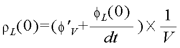
다음으로, X=0 위치에서의 차량의 요레이트 센서로 측정된 헤딩각 변화율을 φ'(v)이라 할 때, X=0 위치에서의 좌측 차선의 추정곡률(ρL(0))은 하기 <수학식 8>과 같다.Next, when the heading angle change rate measured by the yaw rate sensor of the vehicle at the position of X = 0 is defined as φ '(v), the estimated curvature of the left lane at the position of X = 0 (ρ L (0) (8) < / RTI >
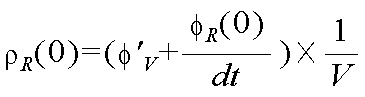
마찬가지로, X=0 위치에서의 우측 차선의 추정곡률(ρR(0))은 하기 <수학식 9>와 같다.Similarly, the estimated curvature? R (0) of the right lane at the position of X = 0 is expressed by Equation (9).
한편, 차량 운동 방정식을 차량 센서들로부터 수신된 정보를 이용하여 표현한 후, 이를 상기 수학식들에서 구한 차선 방정식을 이용한 등가 함수와 비교한다. 상기 비교한 차이를 각 항목별로 나타낸 표는 도 6과 같다. 상기 도 6을 참조하면, 각 파라미터의 차이는 R1 내지 R8까지 표현할 수 있다.Meanwhile, the vehicle motion equation is expressed using information received from the vehicle sensors, and is compared with an equivalent function using the lane equation obtained in the above equations. The table showing the above-mentioned difference by each item is shown in FIG. Referring to FIG. 6, the difference of each parameter can be represented by R1 to R8.
상기 도 6에서 R1은 좌측 차선 위치(Left Lane Position)로서, 좌측 로우 차선 위치(Raw Lane Position) 값과 평균 차선 폭으로 추정된 차선 위치 간의 차이를 의미한다.In FIG. 6, R1 is a left lane position, which means a difference between a left lane position value and a lane position estimated by an average lane width.
R2는 우측 차선 위치(Right Lane Position)로서, 우측 로우 차선 위치(Raw Lane Position) 값과 평균 차선 폭으로 추정된 차선 위치 간의 차이를 의미한다.R2 is the right lane position, which means the difference between the value of the right lane position and the lane position estimated by the average lane width.
R3은 좌측 차선 헤딩각(Left Lane Heading Angle)으로서, 카메라로 추정된 좌측 차선 헤딩각도와 차량센서로 추정된 좌측 차선 헤딩각의 차이를 의미한다.R3 is the left lane heading angle, which means the difference between the left lane heading angle estimated by the camera and the left lane heading angle estimated by the vehicle sensor.
R4는 우측 차선 헤딩각(Right Lane Heading Angle)으로서, 카메라로 추정된 우측 차선 헤딩각도와 차량센서로 추정된 우측 차선 헤딩각의 차이를 의미한다.R4 is the right lane heading angle, which means the difference between the right lane heading angle estimated by the camera and the right lane heading angle estimated by the vehicle sensor.
R5는 양쪽 차선 헤딩각(Both Lane Heading Angle)으로서, 좌/우측간 차선 헤딩각(Lane Heading Angle)의 차이를 의미한다.R5 is the both lane heading angle, which means the difference between the left and right lane heading angles.
R6은 좌측 차선 곡률(Left Lane Curvature)로서, 카메라로 추정된 좌측 차선 곡률과 차량센서로 추정된 좌측 차선 곡률의 차이를 의미한다.R6 is the left lane curvature, which means the difference between the left lane curvature estimated by the camera and the left lane curvature estimated by the vehicle sensor.
R7은 우측 차선 곡률(Right Lane Curvature)로서, 카메라로 추정된 우측 차선 곡률과 차량센서로 추정된 우측 차선 곡률의 차이를 의미한다.R7 is the right lane curvature, which means the difference between the right lane curvature estimated by the camera and the right lane curvature estimated by the vehicle sensor.
R8은 양측 차선 곡률(Both Lane Curvature)로서 좌/우측 차선 곡률의 차이를 의미한다.R8 is the both lane curvature, which means the difference in curvature of the left / right lane.
이와 같이, 각 항목별로 차선 파라미터로부터 산출된 등가 모델과 차량 센서로부터 측정된 값으로부터 추정된 등가 모델을 비교함으로써 차선 데이터의 오검출 여부를 판단할 수 있다.Thus, by comparing the equivalent model calculated from the lane parameter for each item and the equivalent model estimated from the measured value from the vehicle sensor, it is possible to determine whether or not the lane data is erroneously detected.
도 7은 본 발명의 실시예에 따른 실제 차선을 정상적으로 검출한 결과를 나타내는 그래프이다.7 is a graph showing a result of normally detecting an actual lane according to an embodiment of the present invention.
도 7을 참조하면, 본 발명의 실시예에 따른 장치는 상기 도 6과 같이 산출한 R1 내지 R8 까지의 변화량을 실시간으로 복수의 항목들에 대해 동시에 검사한다.Referring to FIG. 7, an apparatus according to an embodiment of the present invention simultaneously checks a plurality of items in real time for a change amount from R1 to R8 calculated as shown in FIG.
즉, 상기 도 6의 R1 내지 R8의 신호를 동시에 검사하며, 각 변화량이 미리 설정한 일정한 임계값을 초과하는 순간을 검출한다.That is, the signals of R1 to R8 of FIG. 6 are checked at the same time, and an instant when each variation amount exceeds a predetermined threshold value is detected.
도 7은 실제 차선을 정상적으로 검출한 결과이며, 도 8에서 볼 수 있듯이 R1 내지 R2의 차이가 설정한 일정한 임계값을 넘지 않는 것을 확인할 수 있다. 따라서, 정상적으로 차선 데이터가 식별되고 있음을 알 수 있다.FIG. 7 is a result of normally detecting an actual lane. As can be seen from FIG. 8, it can be seen that the difference between R1 and R2 does not exceed a predetermined threshold value. Therefore, it can be seen that the lane data is normally identified.
반면, 도 9는 실제 차선과 다르게 차선을 오인식한 상태이며, 도 10에서와 같이 R1 내지 R8 중 일부 신호의 차이에서 미리 설정된 임계값을 초과함을 알 수 있다.On the other hand, FIG. 9 is a state in which the lane is mistakenly recognized differently from the actual lane, and it can be seen that the difference between some of R1 to R8 exceeds a predetermined threshold as shown in FIG.
따라서, 본 발명에 따른 장치에서는 상기 도 10에서 확인한 R1 내지 R8의 변화를 동시에 검사하여, 특정 변화가 미리 설정된 일정 시간 동안 지속되었을 때, 도 11의 표와 같이 오인식 상황을 검출하고 분류한다.Therefore, the apparatus according to the present invention inspects the changes of R1 to R8 identified in FIG. 10 simultaneously, and detects and classifies a misidentified situation as shown in the table of FIG. 11 when a specific change lasts for a preset predetermined time.
이에 따라, 오류 진단 코드(Fault Diagnostic Code)(F(a)를 f(R8)f(R7)f(R6)f(R5)f(R4)f(R3)f(R2)f(R1)과 같이 생성할 수 있다. 상기 생성된 오류 진단 코드의 각 항목은 오류 판단 여부에 따라 'H(오류)' 또는 'L(정상)'로 표현될 수 있다.Accordingly, the fault diagnosis code F (R) f (R7) f (R6) f (R5) f (R4) f Each item of the generated error diagnosis code can be expressed as 'H (error)' or 'L (normal)' according to whether or not an error is determined.
예컨대, 도 11에서 오류 진단 코드가 R8에서 R1의 순서로 'HHLHHLLL'과 같이 표현된다면, 우측 차선 헤딩각 및 곡률 정보가 비정상적인 상태로 진단할 수 있다. 즉, 도 12를 참조하면, 63초와 64초 사이에서 오류 진단 코드의 각 항목이 상기와 같은 상태가 됨을 알 수 있다.For example, if the error diagnosis code is expressed as 'HHLHHLLL' in the order of R8 to R1 in FIG. 11, the right lane heading angle and curvature information can be diagnosed as abnormal. That is, referring to FIG. 12, it can be seen that each item of the error diagnosis code becomes the same state between 63 seconds and 64 seconds.
도 13은 본 발명의 실시예에 따른 오류 진단 코드별 조치를 나타내는 도면이다. 도 13을 참조하면, 상기 도 11과 같은 증상일 경우, 우측 지향각 및 우측 곡률은 이용 가능한 정보(tolerabel)로 판단되므로, 우측 지향각으로 좌측 지향각을 대체하고, 우측 곡률로 좌측 곡률을 대체한다.FIG. 13 is a diagram showing a measure for each error diagnostic code according to an embodiment of the present invention. FIG. Referring to FIG. 13, in the case of the symptom as shown in FIG. 11, since the rightward directional angle and the rightward curvature are determined as available information (tolerabel), the rightward directed angle is replaced with the leftward directed angle, do.
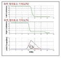
도 14는 본 발명의 실시예에 따른 오인식 발생 시 제어 토크 기여도 축소에 의한 제어 토크 처리 장면을 나타내는 도면이다. 도 14를 참조하면, 본 발명의 실시예에 따라 오인식 발생 시 제어 토크 기여도를 축소하여 제어 토크를 처리할 수 있다. 도 14에서 1410번은 좌측 제어 토크 기여도(%)를 나타내며, 1420번은 우측 제어 토크 기여도(%)를 나타낸다. 또한, 1440번은 오동작 토크값을 나타내며, 1430번은 본 발명에 따라 제어된 안전한 토크값을 나타낸다.FIG. 14 is a view showing a control torque processing scene by reducing the contribution of the control torque in the occurrence of a false sense according to the embodiment of the present invention. FIG. Referring to FIG. 14, according to the embodiment of the present invention, the control torque can be processed by reducing the contribution of the control torque when a false sense occurs. In FIG. 14,
도 15는 본 발명의 실시예에 따른 좌/우측 제어 토크 기여도를 나타내며, 좌측 제어 토크 기여도 및 우측 제어 토크 기여도가 변경되는 해당 프레임에서 본 발명의 실시예에 따라 안전하게 토크가 처리됨을 알 수 있다.FIG. 15 shows the left / right control torque contribution according to an embodiment of the present invention. It can be seen that the torque is safely processed in the corresponding frame in which the left control torque contribution and the right control torque contribution are changed, in accordance with the embodiment of the present invention.
이상과 같이 본 발명에서는 구체적인 구성 요소 등과 같은 특정 사항들과 한정된 실시예 및 도면에 의해 설명되었으나 이는 본 발명의 보다 전반적인 이해를 돕기 위해서 제공된 것일 뿐, 본 발명은 상기의 실시예에 한정되는 것은 아니며, 본 발명이 속하는 분야에서 통상적인 지식을 가진 자라면 이러한 기재로부터 다양한 수정 및 변형이 가능하다.As described above, the present invention has been described with reference to particular embodiments, such as specific elements, and specific embodiments and drawings. However, it should be understood that the present invention is not limited to the above- And various modifications and changes may be made thereto by those skilled in the art to which the present invention pertains.
따라서, 본 발명의 사상은 설명된 실시예에 국한되어 정해져서는 아니되며, 후술하는 특허청구범위뿐 아니라 이 특허청구범위와 균등하거나 등가적 변형이 있는 모든 것들은 본 발명 사상의 범주에 속한다고 할 것이다.
Accordingly, the spirit of the present invention should not be construed as being limited to the embodiments described, and all of the equivalents or equivalents of the claims, as well as the following claims, belong to the scope of the present invention .
300 : 오류 검출 장치 310 : 카메라 센서
320 : 차량 센서 330 : 전자식 조향 장치
410 : 차선 파라미터 생성부 420 : 차량 상태 정보 수신부
430 : 등가 모델 생성부 440 : 오검출 판단부
450 : 토크 제어 인자 조정부 460 : 등가 모델 DB300: error detection device 310: camera sensor
320: vehicle sensor 330: electronic steering device
410: lane parameter generating unit 420: vehicle condition information receiving unit
430: Equivalent model generation unit 440:
450: Torque control factor adjuster 460: Equivalent model DB
Claims (20)
차량에 설치된 각 차량 센서 또는 장치로부터 센싱 또는 측정된 차량 상태 정보들을 수신하는 차량 상태 정보 수신부;
상기 차선 파라미터 생성부로부터 차선 파라미터를 수신하고, 상기 차량 상태 정보 수신부로부터 차량 상태 정보를 수신하여, 상기 차량 파라미터와 차량 상태 정보 간의 시간적 흐름에 대한 상관 관계를 분석하고, 각각의 등가 모델을 생성하는 등가 모델 생성부;
상기 등가 모델 생성부에서 생성한 등가 모델에서 차이가 발생하는 경우를 적어도 하나의 각 오차 항목에 대해 동시에 분석하여 차선 파라미터의 오검출 상황을 판단하고 분류하는 오검출 판단부; 및
상기 오검출 판단부에 의해 차선 파라미터가 오검출된 것으로 판단되면, 오토크의 영향을 억제 또는 감소시킬 수 있도록 미리 설정된 토크 제어 인자 조정 설정에 따라 토크 제어 인자를 조정하는 토크 제어 인자 조정부;를 포함하는, 차선 유지 제어 시스템.
A lane parameter generating unit for generating, as a lane parameter, a relative position of a lane and a vehicle based on information received from a camera installed in the vehicle;
A vehicle state information receiver for receiving vehicle state information sensed or measured from each vehicle sensor or device installed in the vehicle;
A lane parameter from the lane parameter generating section, receiving vehicle state information from the vehicle state information receiving section, analyzing a correlation between the vehicle state parameter and the vehicle state information on the temporal flow, and generating each equivalent model An equivalent model generation unit;
An erroneous detection determining unit for simultaneously analyzing a case where a difference occurs in the equivalent model generated by the equivalent model generating unit for at least one error item to determine and classify the erroneous detection situation of the lane parameter; And
And a torque control factor adjuster for adjusting a torque control factor according to a preset torque control factor adjustment setting so as to suppress or reduce the influence of the mis-torque if it is determined that the lane parameter is erroneously detected by the erroneous detection determination unit A lane keeping control system.
2차원 평면상에서 차선과 차량과의 상대적 위치를 표현한 3차 방정식의 계수를 차선 파라미터로서 생성하는, 차선 유지 제어 시스템.
The method according to claim 1,
A lane keeping control system for generating a coefficient of a cubic equation expressing a relative position of a lane and a vehicle on a two-dimensional plane as a lane parameter.
차량 종 속도, 차량 종 가속도, 차량 요레이트, 조향 각도, 조향 토크, 차량 횡 방향 가속도 중에서 선택된 어느 하나 이상인, 차선 유지 제어 시스템.
The vehicle state information receiving apparatus according to claim 1,
The vehicle longitudinal speed, the vehicle longitudinal acceleration, the vehicle yaw rate, the steering angle, the steering torque, and the vehicle lateral acceleration.
상기 수신된 차선 파라미터 및 차량 상태 정보로부터 상기 차량 파라미터와 차량 상태 정보 간의 시간적 흐름에 대한 상관 관계를 등가 함수로 산출함으로써 등가 모델을 생성하는, 차선 유지 제어 시스템.
The apparatus of claim 1,
And generates an equivalent model by calculating a correlation between the received lane parameter and vehicle state information on the temporal flow between the vehicle parameter and the vehicle state information as an equivalent function.
상기 등가 모델 생성부에서 생성한 등가 모델에서의 차이값이 미리 설정된 임계값을 초과할 때 오검출 상황으로 판단하는, 차선 유지 제어 시스템.
The apparatus according to claim 1,
And judges the false detection situation when the difference value in the equivalent model generated by the equivalent model generation unit exceeds a preset threshold value.
상기 등가 모델 생성부에서 생성한 등가 모델에서의 차이값이 미리 설정된 시간 이상 동안 미리 설정된 임계값을 초과할 때 오검출 상황으로 판단하는, 차선 유지 제어 시스템.
6. The apparatus according to claim 5,
Wherein the lane departure control system determines that an error is detected when the difference value in the equivalent model generated by the equivalent model generator exceeds a preset threshold value for a predetermined time or longer.
좌측 차선 위치, 우측 차선 위치, 좌측 차선 헤딩각, 우측 차선 헤딩각, 양쪽 차선 헤딩각, 좌측 차선 곡률, 우측 차선 곡률, 양측 차선 곡률 중에서 선택된 어느 하나 이상인, 차선 유지 제어 시스템.
The method according to claim 1,
A left lane heading position, a left lane heading position, a left lane heading angle, a right lane heading angle, a left lane heading angle, a left lane curvature, a right lane curvature, and a bilateral lane curvature.
적어도 하나의 토크 제어 인자를 다른 신호로 대체, 적어도 하나의 토크 제어 인자를 격리 및 적어도 하나의 토크 제어 인자를 조절하는 것 중에서 선택된 어느 하나인, 차선 유지 제어 시스템.
The torque control apparatus according to claim 1, wherein the preset torque control parameter adjustment setting of the torque control parameter adjuster
Wherein at least one torque control factor is replaced by another signal, at least one torque control factor is isolated and at least one torque control factor is adjusted.
차량에 설치되어 적어도 하나의 차량 상태 정보들을 센싱하는 적어도 하나의 차량 센서;
상기 차량 카메라로부터 수집된 차선 데이터로부터 차선 파라미터를 생성하고, 상기 차량 센서로부터 차량 상태 정보를 수신하여, 상기 차선 파라미터와 차량 상태 정보 간의 시간적 흐름에 대한 상관 관계를 분석하고, 각각의 등가 모델을 생성하여 상기 차선 데이터의 오검출 여부를 판단하는 오류 검출 장치; 및
상기 오류 검출 장치의 각 오차 항목에 대한 차선 파라미터의 오검출 상황에 따라 상기 오류 검출 장치로부터 조향 토크 신호를 수신하고, 운전자에 대한 어시스트 토크에 반영하여 조향 장치를 제어하는 전자식 조향 장치;를 포함하는, 차량 제어 시스템.
A vehicle camera installed in the vehicle and collecting lane data;
At least one vehicle sensor installed in the vehicle and sensing at least one vehicle condition information;
Generating lane parameters from the lane data collected from the vehicle camera, receiving vehicle state information from the vehicle sensor, analyzing correlations between the lane parameter and vehicle state information over time, and generating each equivalent model An error detection device for determining whether or not the lane data is erroneously detected; And
And an electronic steering device for receiving the steering torque signal from the error detection device in accordance with the erroneous detection condition of the lane parameter for each error item of the error detection device and reflecting the assist torque to the driver to control the steering device , Vehicle control system.
차량에 설치된 카메라로부터 수신된 정보에 의해 차선과 차량과의 상대적 위치를 차선 파라미터로서 생성하는 차선 파라미터 생성부;
차량에 설치된 각 차량 센서 또는 장치로부터 센싱 또는 측정된 차량 상태 정보들을 수신하는 차량 상태 정보 수신부;
상기 차선 파라미터 생성부로부터 차선 파라미터를 수신하고, 상기 차량 상태 정보 수신부로부터 차량 상태 정보를 수신하여, 상기 차량 파라미터와 차량 상태 정보 간의 시간적 흐름에 대한 상관 관계를 분석하고, 각각의 등가 모델을 생성하는 등가 모델 생성부;
상기 등가 모델 생성부에서 생성한 등가 모델에서 차이가 발생하는 경우를 적어도 하나의 각 오차 항목에 대해 동시에 분석하여 차선 파라미터의 오검출 상황을 판단하고 분류하는 오검출 판단부; 및
상기 오검출 판단부에 의해 차선 파라미터가 오검출된 것으로 판단되면, 오토크의 영향을 억제 또는 감소시킬 수 있도록 미리 설정된 토크 제어 인자 조정 설정에 따라 토크 제어 인자를 조정하는 토크 제어 인자 조정부;를 포함하는, 차량 제어 시스템.
The system according to claim 9,
A lane parameter generating unit for generating, as a lane parameter, a relative position of a lane and a vehicle based on information received from a camera installed in the vehicle;
A vehicle state information receiver for receiving vehicle state information sensed or measured from each vehicle sensor or device installed in the vehicle;
A lane parameter from the lane parameter generating section, receiving vehicle state information from the vehicle state information receiving section, analyzing a correlation between the vehicle state parameter and the vehicle state information on the temporal flow, and generating each equivalent model An equivalent model generation unit;
An erroneous detection determining unit for simultaneously analyzing a case where a difference occurs in the equivalent model generated by the equivalent model generating unit for at least one error item to determine and classify the erroneous detection situation of the lane parameter; And
And a torque control factor adjuster for adjusting a torque control factor according to a preset torque control factor adjustment setting so as to suppress or reduce the influence of the mis-torque if it is determined that the lane parameter is erroneously detected by the erroneous detection determination unit The vehicle control system.
차량에 설치된 각 차량 센서 또는 장치로부터 센싱 또는 측정된 차량 상태 정보들을 수신하는 단계;
상기 수신된 차량 파라미터와 차량 상태 정보 간의 시간적 흐름에 대한 상관 관계를 분석하고, 각각의 등가 모델을 생성하는 단계;
상기 생성한 등가 모델에서 차이가 발생하는 경우를 적어도 하나의 각 오차 항목에 대해 동시에 분석하여 차선 파라미터의 오검출 상황을 판단하고 분류하는 단계; 및
상기 판단 결과 차선 파라미터가 오검출된 것으로 판단되면, 오토크의 영향을 억제 또는 감소시킬 수 있도록 미리 설정된 토크 제어 인자 조정 설정에 따라 토크 제어 인자를 조정하는 단계;를 포함하는, 차선 유지 보조를 위한 차선 데이터 오류 검출 방법.
Generating as a lane parameter a relative position of a lane and a vehicle by information received from a camera installed in the vehicle;
Receiving vehicle status information sensed or measured from each vehicle sensor or device installed in the vehicle;
Analyzing a correlation between the received vehicle parameter and vehicle state information on a temporal flow, and generating each equivalent model;
Analyzing a case where a difference occurs in the generated equivalent model for at least one error item simultaneously to determine and classify the false detection situation of the lane parameter; And
And adjusting the torque control factor according to a preset torque control factor adjustment setting so as to suppress or reduce the influence of the mis-torque if it is determined that the lane parameter is erroneously detected as a result of the determination. Lane data error detection method.
2차원 평면상에서 차선과 차량과의 상대적 위치를 표현한 3차 방정식의 계수를 차선 파라미터로서 생성하는, 차선 유지 보조를 위한 차선 데이터 오류 검출 방법.
12. The method of claim 11, wherein generating as the lane parameter comprises:
A method of detecting a lane data error for lane keeping assistance, the method comprising: generating a coefficient of a cubic equation expressing a relative position of a lane and a vehicle on a two dimensional plane as a lane parameter.
차량 종 속도, 차량 종 가속도, 차량 요레이트, 조향 각도, 조향 토크, 차량 횡 방향 가속도 중에서 선택된 어느 하나 이상인, 차선 유지 보조를 위한 차선 데이터 오류 검출 방법.
12. The method according to claim 11,
The vehicle longitudinal speed, the vehicle longitudinal acceleration, the vehicle yaw rate, the steering angle, the steering torque, and the lateral acceleration of the vehicle.
상기 수신된 차선 파라미터 및 차량 상태 정보로부터 상기 차량 파라미터와 차량 상태 정보 간의 시간적 흐름에 대한 상관 관계를 등가 함수로 산출함으로써 등가 모델을 생성하는, 차선 유지 보조를 위한 차선 데이터 오류 검출 방법.
12. The method of claim 11, wherein generating the equivalent model comprises:
And generating an equivalent model by calculating a correlation between the received lane parameter and vehicle state information on a temporal flow between the vehicle parameter and the vehicle state information as an equivalent function, thereby generating an equivalent model.
상기 생성한 등가 모델에서의 차이값이 미리 설정된 임계값을 초과할 때 오검출 상황으로 판단하는, 차선 유지 보조를 위한 차선 데이터 오류 검출 방법.
The method of claim 11, wherein the determining and classifying the false-
And determining that a false detection situation is detected when the difference value in the generated equivalent model exceeds a preset threshold value.
상기 등가 모델 생성부에서 생성한 등가 모델에서의 차이값이 미리 설정된 시간 이상 동안 미리 설정된 임계값을 초과할 때 오검출 상황으로 판단하는, 차선 유지 보조를 위한 차선 데이터 오류 검출 방법.
16. The method of claim 15, wherein the determining and classifying the false-
When the difference value in the equivalent model generated by the equivalent model generation unit exceeds a preset threshold value for a predetermined time or longer, the lane data error detection method for lane-keeping assistance.
좌측 차선 위치, 우측 차선 위치, 좌측 차선 헤딩각, 우측 차선 헤딩각, 양쪽 차선 헤딩각, 좌측 차선 곡률, 우측 차선 곡률, 양측 차선 곡률 중에서 선택된 어느 하나 이상인, 차선 유지 보조를 위한 차선 데이터 오류 검출 방법.
12. The method of claim 11,
Lane data error detection method for lane keeping assist, which is selected from left lane position, right lane position, left lane heading angle, right lane heading angle, both lane heading angle, left lane curvature, right lane curvature, .
적어도 하나의 토크 제어 인자를 다른 신호로 대체, 적어도 하나의 토크 제어 인자를 격리 및 적어도 하나의 토크 제어 인자를 조절하는 것 중에서 선택된 어느 하나인, 차선 유지 보조를 위한 차선 데이터 오류 검출 방법.
The torque control method according to claim 11,
Wherein at least one torque control factor is replaced by another signal, at least one torque control factor is isolated and at least one torque control factor is adjusted.
차량에 설치된 적어도 하나의 차량 센서로부터 적어도 하나의 차량 상태 정보들을 센싱하는 단계;
상기 차량 카메라로부터 수집된 차선 데이터로부터 차선 파라미터를 생성하는 단계;
상기 차량 센서로부터 차량 상태 정보를 수신하여, 상기 차선 파라미터와 차량 상태 정보 간의 시간적 흐름에 대한 상관 관계를 분석하고, 각각의 등가 모델을 생성하는 단계;
상기 생성된 등가 모델로부터 상기 차선 데이터의 오검출 여부를 판단하는 단계; 및
상기 오검출 여부 판단에 따른 각 오차 항목에 대한 차선 파라미터의 오검출 상황에 따라 조향 토크 신호를 생성하여 전자식 조향 장치에 제공하는 단계;를 포함하는, 차량 제어 방법.
Collecting lane data from a vehicle camera installed in the vehicle;
Sensing at least one vehicle condition information from at least one vehicle sensor installed in the vehicle;
Generating a lane parameter from lane data collected from the vehicle camera;
Receiving vehicle state information from the vehicle sensor, analyzing a correlation between the lane parameter and vehicle state information on a temporal flow, and generating each equivalent model;
Determining whether the lane data is erroneously detected from the generated equivalent model; And
And generating a steering torque signal in accordance with an erroneous detection situation of a lane parameter for each error item according to the erroneous detection whether or not the erroneous detection is performed, and providing the generated steering torque signal to the electronic steering device.
Priority Applications (4)
| Application Number | Priority Date | Filing Date | Title |
|---|---|---|---|
| KR1020130013973A KR101436624B1 (en) | 2013-02-07 | 2013-02-07 | Apparatus, method and computer readable recording medium for detecting an error of a lane data for lane maintenance support |
| JP2014014062A JP5768150B2 (en) | 2013-02-07 | 2014-01-29 | Lane maintaining control system, method and computer-readable recording medium |
| US14/168,577 US9469343B2 (en) | 2013-02-07 | 2014-01-30 | System, method, and computer-readable recording medium for lane keeping control |
| DE102014001560.2A DE102014001560A1 (en) | 2013-02-07 | 2014-02-05 | SYSTEM, METHOD AND COMPUTER READABLE RECORDING MEDIUM FOR A TRACK LEVER CONTROL |
Applications Claiming Priority (1)
| Application Number | Priority Date | Filing Date | Title |
|---|---|---|---|
| KR1020130013973A KR101436624B1 (en) | 2013-02-07 | 2013-02-07 | Apparatus, method and computer readable recording medium for detecting an error of a lane data for lane maintenance support |
Publications (2)
| Publication Number | Publication Date |
|---|---|
| KR20140100787A KR20140100787A (en) | 2014-08-18 |
| KR101436624B1 true KR101436624B1 (en) | 2014-11-03 |
Family
ID=51258911
Family Applications (1)
| Application Number | Title | Priority Date | Filing Date |
|---|---|---|---|
| KR1020130013973A Active KR101436624B1 (en) | 2013-02-07 | 2013-02-07 | Apparatus, method and computer readable recording medium for detecting an error of a lane data for lane maintenance support |
Country Status (4)
| Country | Link |
|---|---|
| US (1) | US9469343B2 (en) |
| JP (1) | JP5768150B2 (en) |
| KR (1) | KR101436624B1 (en) |
| DE (1) | DE102014001560A1 (en) |
Families Citing this family (17)
| Publication number | Priority date | Publication date | Assignee | Title |
|---|---|---|---|---|
| JP6485915B2 (en) * | 2015-10-28 | 2019-03-20 | 本田技研工業株式会社 | Road lane marking recognition device, vehicle control device, road lane marking recognition method, and road lane marking recognition program |
| US9775128B2 (en) * | 2016-01-21 | 2017-09-26 | Ford Global Technologies, Llc | Vehicular connectivity map |
| KR102520242B1 (en) * | 2016-04-20 | 2023-04-11 | 주식회사 에이치엘클레무브 | Lane Keeping Control System and Steering Control Method |
| US10203408B2 (en) * | 2016-07-29 | 2019-02-12 | Faraday & Future Inc. | Method and apparatus for detection and ranging fault detection and recovery |
| KR102452546B1 (en) * | 2016-12-15 | 2022-10-07 | 현대자동차주식회사 | Apparatus for path planning of vehicle and method thereof |
| DE102017208384A1 (en) * | 2017-05-18 | 2018-11-22 | Ford Global Technologies, Llc | Method for operating a motor vehicle with a traffic jam assistant |
| US10913495B2 (en) | 2017-06-12 | 2021-02-09 | Steering Solutions Ip Holding Corporation | Vehicle safety steering system |
| US10395444B1 (en) * | 2017-08-10 | 2019-08-27 | Zoox, Inc. | Vehicle self-diagnostics |
| JP7053211B2 (en) * | 2017-10-04 | 2022-04-12 | 株式会社Soken | Driving support device |
| KR102485352B1 (en) * | 2018-04-11 | 2023-01-05 | 현대자동차주식회사 | Vehicle apparatus, system having the same and method for changing automatically operable range thereof |
| US11351989B2 (en) | 2018-04-11 | 2022-06-07 | Hyundai Motor Company | Vehicle driving controller, system including the same, and method thereof |
| KR102115915B1 (en) * | 2018-10-08 | 2020-05-27 | 주식회사 만도 | Apparatus and method for determining distortion in road lane recognition |
| TWI689433B (en) * | 2018-11-21 | 2020-04-01 | 財團法人車輛研究測試中心 | Lane tracking method and system for autonomous driving vehicles |
| US11619947B2 (en) * | 2019-04-01 | 2023-04-04 | Valeo Schalter Und Sensoren Gmbh | Wireless communication for aligning a vehicle to a wireless charger |
| US11409278B2 (en) * | 2019-07-26 | 2022-08-09 | Zoox, Inc. | System and method for providing a teleoperation instruction to an autonomous vehicle |
| US11892835B2 (en) | 2019-07-26 | 2024-02-06 | Zoox, Inc. | System and method for controlling an autonomous vehicle |
| KR20230055804A (en) | 2021-10-19 | 2023-04-26 | 현대자동차주식회사 | Lane keeping apparatus and method thereof |
Citations (1)
| Publication number | Priority date | Publication date | Assignee | Title |
|---|---|---|---|---|
| KR100901414B1 (en) | 2007-11-23 | 2009-06-05 | 현대자동차주식회사 | Lane Departure Prevention System |
Family Cites Families (44)
| Publication number | Priority date | Publication date | Assignee | Title |
|---|---|---|---|---|
| JP3034121B2 (en) * | 1992-04-17 | 2000-04-17 | 株式会社豊田中央研究所 | Unmanned vehicle control device |
| US7421321B2 (en) * | 1995-06-07 | 2008-09-02 | Automotive Technologies International, Inc. | System for obtaining vehicular information |
| JPH1166488A (en) * | 1997-08-21 | 1999-03-09 | Honda Motor Co Ltd | White line recognizing device |
| US7647180B2 (en) * | 1997-10-22 | 2010-01-12 | Intelligent Technologies International, Inc. | Vehicular intersection management techniques |
| JP3719116B2 (en) * | 2000-08-30 | 2005-11-24 | トヨタ自動車株式会社 | Vehicle driving force control device |
| JP3601487B2 (en) * | 2000-11-20 | 2004-12-15 | トヨタ自動車株式会社 | Vehicle braking / driving force control device |
| JP2003040127A (en) * | 2001-07-27 | 2003-02-13 | Mitsubishi Motors Corp | Travel lane departure prevention device |
| JP2003040132A (en) * | 2001-07-27 | 2003-02-13 | Mitsubishi Motors Corp | Travel lane departure prevention device |
| US6651771B2 (en) * | 2001-10-20 | 2003-11-25 | Ford Global Technologies, Llc | H-infinity control and gain scheduling method for electric power assist steering system |
| JP3956693B2 (en) * | 2001-12-27 | 2007-08-08 | トヨタ自動車株式会社 | Integrated vehicle motion controller |
| JP3689065B2 (en) * | 2002-05-13 | 2005-08-31 | 三菱電機株式会社 | Vehicle travel control device |
| US7124027B1 (en) * | 2002-07-11 | 2006-10-17 | Yazaki North America, Inc. | Vehicular collision avoidance system |
| US7522091B2 (en) * | 2002-07-15 | 2009-04-21 | Automotive Systems Laboratory, Inc. | Road curvature estimation system |
| US7272482B2 (en) * | 2002-09-30 | 2007-09-18 | Nissan Motor Co., Ltd. | Preceding-vehicle following control system |
| US6819998B2 (en) * | 2002-11-26 | 2004-11-16 | General Motors Corporation | Method and apparatus for vehicle stability enhancement system |
| US7239949B2 (en) * | 2003-02-26 | 2007-07-03 | Ford Global Technologies, Llc | Integrated sensing system |
| US7510038B2 (en) * | 2003-06-11 | 2009-03-31 | Delphi Technologies, Inc. | Steering system with lane keeping integration |
| JP3818653B2 (en) * | 2003-06-26 | 2006-09-06 | トヨタ自動車株式会社 | Vehicle travel support device |
| US7212901B2 (en) * | 2003-10-29 | 2007-05-01 | Nissan Motor Co., Ltd. | Lane departure prevention apparatus |
| DE102004019337A1 (en) * | 2004-04-21 | 2005-11-17 | Siemens Ag | Assistance system for motor vehicles |
| JP4211685B2 (en) * | 2004-05-31 | 2009-01-21 | トヨタ自動車株式会社 | Driving assistance device |
| JP4349210B2 (en) * | 2004-06-02 | 2009-10-21 | トヨタ自動車株式会社 | Driving assistance device |
| JP4390631B2 (en) * | 2004-06-02 | 2009-12-24 | トヨタ自動車株式会社 | Boundary line detection device |
| JP4007355B2 (en) * | 2004-09-21 | 2007-11-14 | 日産自動車株式会社 | Lane tracking control device |
| JP4696539B2 (en) * | 2004-11-26 | 2011-06-08 | アイシン精機株式会社 | Vehicle travel support device |
| JP4457891B2 (en) * | 2004-12-28 | 2010-04-28 | 日産自動車株式会社 | Lane departure prevention device |
| US20070055431A1 (en) * | 2005-09-07 | 2007-03-08 | Weiwen Deng | Method and apparatus for preview-based vehicle lateral control |
| JP4108706B2 (en) * | 2005-10-31 | 2008-06-25 | 三菱電機株式会社 | Lane departure prevention device |
| WO2007063397A1 (en) * | 2005-12-01 | 2007-06-07 | Toyota Jidosha Kabushiki Kaisha | Driving assistance system and driving assistance method |
| US7400963B2 (en) * | 2005-12-09 | 2008-07-15 | Gm Global Technology Operations, Inc. | Speed control method for vehicle approaching and traveling on a curve |
| KR100766596B1 (en) | 2006-01-20 | 2007-10-11 | 한민홍 | Lane Keeping Steering Control Method of Vehicle |
| JP4721279B2 (en) * | 2006-03-29 | 2011-07-13 | 富士重工業株式会社 | Lane tracking support device |
| JP4793094B2 (en) * | 2006-05-17 | 2011-10-12 | 株式会社デンソー | Driving environment recognition device |
| JP2009169945A (en) * | 2007-12-18 | 2009-07-30 | Fujitsu Ten Ltd | Simulation apparatus and simulation method |
| US9090285B2 (en) * | 2008-12-05 | 2015-07-28 | Volkswagen Group Of America, Inc. | Method for providing a lanekeeping assistance based on modifying mechanical sources of steering torques |
| JP5200926B2 (en) * | 2008-12-26 | 2013-06-05 | トヨタ自動車株式会社 | Driving assistance device |
| US20100209884A1 (en) * | 2009-02-18 | 2010-08-19 | Gm Global Technology Operations, Inc. | Driving skill recognition based on vehicle left and right turns |
| US20100209891A1 (en) * | 2009-02-18 | 2010-08-19 | Gm Global Technology Operations, Inc. | Driving skill recognition based on stop-and-go driving behavior |
| US8738228B2 (en) * | 2009-10-30 | 2014-05-27 | Ford Global Technologies, Llc | Vehicle and method of tuning performance of same |
| US8258934B2 (en) * | 2009-10-30 | 2012-09-04 | Ford Global Technologies, Llc | Vehicle and method of advising a driver therein |
| KR20130013973A (en) | 2011-07-29 | 2013-02-06 | 우석대학교 산학협력단 | Apparatus for charge of hybrid vehicles |
| JP5692044B2 (en) * | 2011-12-21 | 2015-04-01 | トヨタ自動車株式会社 | Vehicle state quantity estimation device, vehicle steering control device |
| JP5451911B2 (en) * | 2013-01-18 | 2014-03-26 | 富士重工業株式会社 | Lane departure prevention control device |
| JP6040788B2 (en) * | 2013-01-30 | 2016-12-07 | トヨタ自動車株式会社 | Track line reliability determination device and driving support control device |
-
2013
- 2013-02-07 KR KR1020130013973A patent/KR101436624B1/en active Active
-
2014
- 2014-01-29 JP JP2014014062A patent/JP5768150B2/en active Active
- 2014-01-30 US US14/168,577 patent/US9469343B2/en active Active
- 2014-02-05 DE DE102014001560.2A patent/DE102014001560A1/en active Pending
Patent Citations (1)
| Publication number | Priority date | Publication date | Assignee | Title |
|---|---|---|---|---|
| KR100901414B1 (en) | 2007-11-23 | 2009-06-05 | 현대자동차주식회사 | Lane Departure Prevention System |
Also Published As
| Publication number | Publication date |
|---|---|
| US20140218508A1 (en) | 2014-08-07 |
| US9469343B2 (en) | 2016-10-18 |
| KR20140100787A (en) | 2014-08-18 |
| JP5768150B2 (en) | 2015-08-26 |
| DE102014001560A1 (en) | 2014-08-28 |
| JP2014151906A (en) | 2014-08-25 |
Similar Documents
| Publication | Publication Date | Title |
|---|---|---|
| KR101436624B1 (en) | Apparatus, method and computer readable recording medium for detecting an error of a lane data for lane maintenance support | |
| CN110733501B (en) | Methods for automatic collision avoidance | |
| CN110087965B (en) | System for vehicle | |
| US9595197B2 (en) | Lateral control apparatus of vehicle and control method of the same | |
| CN116390879B (en) | System and method for avoiding an imminent collision | |
| US8321066B2 (en) | Method for determining free spaces in the vicinity of a motor vehicle, in particular in the vicinity relevant to the vehicle operation | |
| JP6404634B2 (en) | Consistent behavior generation of predictive advanced driver assistance systems | |
| US11780434B2 (en) | Lane change intention estimation of a vehicle | |
| US20150274161A1 (en) | Method for operating a driver assistance system of a vehicle | |
| KR102048186B1 (en) | Apparatus and method for judging drowsiness drive using driving pattern of vehicle | |
| KR102592830B1 (en) | Apparatus and method for predicting sensor fusion target in vehicle and vehicle including the same | |
| KR20210138463A (en) | Method and Apparatus for Preventing VRU Accident | |
| US12036983B2 (en) | Method for detecting driver's hands on/off steering wheel during driving and system thereof | |
| US11292463B2 (en) | Determination of a control signal for an in-part-autonomous vehicle | |
| US20220314940A1 (en) | Vehicle rear warning system and control method thereof | |
| US20200148260A1 (en) | Lane changing system and lane changing method | |
| US20190009793A1 (en) | Method and device for controlling at least one driver interaction system | |
| US10266181B2 (en) | Tire blowout control | |
| US20230406298A1 (en) | Method for Training and Operating Movement Estimation of Objects | |
| CN115675395A (en) | Autonomous Emergency Braking (AEB) based on vehicle steering status | |
| KR20170019638A (en) | Method and Apparutus for Controlling Collision Avoidance Brake by Predicting Locus of Turn | |
| EP4017773B1 (en) | A method for quantifying extreme traffic behavior | |
| KR102257893B1 (en) | Apparatus of providing lane change information, method of providing lane change information and readable medium for performing the method | |
| CN115713746A (en) | Authentication of surrounding objects perceived by ADS equipped vehicles | |
| KR20230023080A (en) | Power steering apparatus and method for autonomous vehicle |
Legal Events
| Date | Code | Title | Description |
|---|---|---|---|
| A201 | Request for examination | ||
| PA0109 | Patent application |
Patent event code: PA01091R01D Comment text: Patent Application Patent event date: 20130207 |
|
| PA0201 | Request for examination | ||
| E701 | Decision to grant or registration of patent right | ||
| PE0701 | Decision of registration |
Patent event code: PE07011S01D Comment text: Decision to Grant Registration Patent event date: 20140616 |
|
| PG1501 | Laying open of application | ||
| PR0701 | Registration of establishment |
Comment text: Registration of Establishment Patent event date: 20140826 Patent event code: PR07011E01D |
|
| PR1002 | Payment of registration fee |
Payment date: 20140827 End annual number: 3 Start annual number: 1 |
|
| PG1601 | Publication of registration | ||
| FPAY | Annual fee payment |
Payment date: 20170622 Year of fee payment: 4 |
|
| PR1001 | Payment of annual fee |
Payment date: 20170622 Start annual number: 4 End annual number: 4 |
|
| FPAY | Annual fee payment |
Payment date: 20180626 Year of fee payment: 5 |
|
| PR1001 | Payment of annual fee |
Payment date: 20180626 Start annual number: 5 End annual number: 5 |
|
| PR1001 | Payment of annual fee |
Payment date: 20190626 Start annual number: 6 End annual number: 6 |
|
| PR1001 | Payment of annual fee |
Payment date: 20200617 Start annual number: 7 End annual number: 7 |
|
| PR1001 | Payment of annual fee |
Payment date: 20210802 Start annual number: 8 End annual number: 8 |
|
| PR1001 | Payment of annual fee |
Payment date: 20220620 Start annual number: 9 End annual number: 9 |
|
| PR1001 | Payment of annual fee |
Payment date: 20230622 Start annual number: 10 End annual number: 10 |
|
| PR1001 | Payment of annual fee |
Payment date: 20240624 Start annual number: 11 End annual number: 11 |
|
| PR1001 | Payment of annual fee |
Payment date: 20250623 Start annual number: 12 End annual number: 12 |